Embed Size (px)
Citation preview
1© Copyright 2016, PROTECTA
USER INSTRUCTION MANUAL TIE-OFF ADAPTOR ANCHORAGE CONNECTORS
This manual is intended to meet the Manufacturer's Instructions as required by ANSI-Z359.1 and should be used as part of an employee training program as required by OSHA.
Instructions for the following series products:
Tie-Off Adaptor Anchorage Connectors
(See inside back cover for specifi c model numbers.)
Form: 5902224 Rev: H
1 - Anchorage Connectors
AWeb Loop Choker
Tie-Off Adapter
BWeb Strap
ChokerTie-Off Adapter
CCable Choker
Tie-Off Adapter
DAnchorage Extension
ELoop End
Cable Tie-Off Adapter
FTwin Ring
Cable Tie-Off Adapter
GLoop End
Cable Tie-Off Adapter
WARNING: This product is part of a personal fall arrest, restraint, work positioning, suspension, or rescue system. The user must follow the manufacturer's instructions for each component of the system. These instructions must be provided to the user of this equipment. The user must read and understand these instructions before using this equipment. Manufacturer's instructions must be followed for proper use and maintenance of this equipment. Alterations or misuse of this product, or failure to follow instructions, may result in serious injury or death.
IMPORTANT: If you have questions on the use, care, or suitability of this equipment for your application, contact PROTECTA.
IMPORTANT: Record the product identifi cation information from the ID label in the inspection and maintenance log in section 8.0 of this manual.
Trusted Quality Fall Protection
2
DESCRIPTION
A. Web Loop Choker Tie-Off Adaptor: Pass through type anchorage connector; 1 3/4 in. polyester webbing strength member, 3 in. wide scuff guard. Total length: 6 ft. (1.8 m) See Figure 1.
B. Web Strap Choker Tie-Off Adaptor: Pass through type anchorage connector; 2 in.polyester webbing strength member, Available in various lengths. See Figure 1.
C. Cable Choker Tie-Off Adaptor: Pass through type anchorage connector; 3/8 in. diameter galvanized wire rope, zinc coated attachment rings. Available in various lengths. See Figure 1.
D. Cable Tie-Off Adaptor: Sling type anchorage connector; coated, galvanized, 1/4 in. diameter wire rope, AJ520A snap hook at one end, 3 in. diameter attachment ring at the other end. Available in stainless steel also. See Figure 1.
E. Loop End Cable Tie-Off Adaptor: Sling type anchorage connector; 1/4 in. diameter coated, galvanized wire rope, thimble/eye swaged ends. Standard length: 3 ft (0.9 m) . Available in various lengths and with coating. See Figure 1.
F. Twin Ring Cable Tie-Off Adaptor: Sling type anchorage connector; coated, galvanized, 1/4 in. diameter wire rope, 3,600 lb gated carabiner at one end, Two 1 in. diameter D-rings at the other end.
G. Loop End Wire Rope Anchor: Sling type anchorage connector; 1/4 in. diameter coated, galvanized wire rope, swaged ends. Standard length: 3 ft (0.9 m) . Available in various lengths and with coating. See Figure 1.
1.0 APPLICATIONS
1.1 PURPOSE: The Tie-Off Adaptor is designed to be used as an anchorage connector for a personal fall arrest, restraint, work positioning, suspension or rescue system. Tie-Off Adaptors may be used as anchorage connectors for a horizontal lifeline if the system is designed, installed and used under the supervision of a qualifi ed person. Do not hang, lift, or support tools or equipment from this equipment.
A. PERSONAL FALL ARREST: The anchorage connector is used as a component of a personal fall arrest system. Personal fall arrest systems typically include a full body harness and a connecting subsystem, (energy absorbing lanyard). Maximum permissible free fall is 6 feet (1.8 m).
B. RESTRAINT: The anchorage connector is used as a component of a restraint system to prevent the user from reaching a fall hazard. Restraint systems typically include a full body harness and a lanyard or restraint line. No vertical free fall is permitted.
C. WORK POSITIONING: The anchorage connector is used as a component of a work positioning system to support the user at a work position. Work positioning systems typically include a full body harness, positioning lanyard, and a back-up personal fall arrest system. Maximum permissible free fall is 2 feet (0.6 m).
D. PERSONNEL RIDING: The anchorage connector is used as a component of a personnel riding system to suspend or transport the user vertically. Personnel riding systems typically include a full body harness, boatswain's chair or seat board, and a back-up personal fall arrest system. No vertical free fall is permitted.
E. RESCUE: The anchorage connector is used as a component of a rescue system. Rescue systems are configured depending on the type of rescue. No vertical free fall is permitted.
1.2 LIMITATIONS: Consider the following application limitations before using this product:
A. CAPACITY: These anchorage connectors are designed for use by persons with a combined weight (clothing, tools, etc.) of no more than 310 lbs (141 kg). No more than one personal protective system may be connected at one time.
B. FREE FALL: Personal fall arrest systems used with this equipment must be rigged to limit the free fall to 6 feet (1.8 m) (ANSI Z359.1). A minimum safety factor of 2 feet (0.6 m) should exist between the worker's feet and the level below at the instant the fall is arrested. See personal fall arrest system manufacturer’s instructions for more information. Restraint systems must be rigged so that no vertical free fall is possible. Work positioning systems must be rigged so that free fall is limited to 2 feet (0.6 m) or less. Personnel riding systems must be rigged so that no vertical free fall is possible. Rescue systems must be rigged so that no vertical free fall is possible.
3
2 - Fall Clearance 3 - Swing Fall
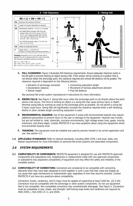
RD = LL + DD + HH + CRD Required Fall Clearance Distance
LL Length of Lanyard (Specifi ed on labeling)
DD Deceleration Distance = 4 ft (1.2 m) except:
• for ANSI/OSHA Lanyards with Free Fall greater than 6 ft (1.8 m) up to 12 ft (3.7 m), or user weights greater than 310 lbs (141 kg) up to 420 lbs (191 kg); add 1 ft (0.3 m): DD = 5 ft (1.5 m)
• for CSA E6 Lanyards, add 1.7 ft. (0.5 m):DD = 5.7 ft (1.7 m)
HH Height of Suspended Worker
C Safety Factor = 1.5 ft (0.5 m)(Factors in D-Ring Slide and Harness Stretch.)
Example: Assuming a 6 ft (1.8 m) tall user with a typical 6 ft (1.8 m) lanyard with 6 ft (1.8 m) Free Fall, Fall Clearance calculation would be as follows:
RD = LL + DD + HH + CRD = 6 ft + 4 ft + 6 ft + 1.5 ft = 17.5 ftRD = 1.8 m + 1.2 m + 1.8 m + 0.5 m = 5.3 m
RD
LL
DD
HH
C
Swing Fall Hazard
C. FALL CLEARANCE: Figure 2 illustrates Fall Clearance requirements. Ensure adequate clearance exists in the fall path to prevent striking an object during a fall. If the worker will be working at a position that is not directly below the anchorage point, the clearance required and vertical fall distance will be greater. The clearance required is dependent on the following factors:
• Elevation of anchorage connector • Connecting subsystem length • Deceleration distance • Movement of harness attachment element • Worker height • Free fall distance
See personal fall arrest system manufacturer’s instructions for more information.
D. SWING FALLS: See Figure 3. Swing falls occur when the anchorage point is not directly above the point where a fall occurs. The force of striking an object in a swing fall may cause serious injury or death. Minimize swing falls by working as close to the anchorage point as possible. Do not permit a swing fall if injury could occur. Swing falls will significantly increase the clearance required when a self retracting lifeline or other variable length connecting subsystem is used.
E. ENVIRONMENTAL HAZARDS: Use of this equipment in areas with environmental hazards may require additional precautions to prevent injury to the user or damage to the equipment. Hazards may include, but are not limited to: heat, chemicals, corrosive environments, high voltage power lines, gases, moving machinery, and sharp edges. Contact PROTECTA if you have questions about using this equipment where environmental hazards exist.
F. TRAINING: This equipment must be installed and used by persons trained in its correct application and use. See section 4.0.
1.3 APPLICABLE STANDARDS: Refer to national standards, including ANSI Z359.1 and local, state, and federal requirements for more information on personal fall arrest systems and associated components.
2.0 SYSTEM REQUIREMENTS
2.1 COMPATIBILITY OF COMPONENTS: PROTECTA equipment is designed for use with PROTECTA approved components and subsystems only. Substitutions or replacements made with non-approved components or subsystems may jeopardize compatibility of equipment and may effect the safety and reliability of the complete system.
2.2 COMPATIBILITY OF CONNECTORS: Connectors are considered to be compatible with connecting elements when they have been designed to work together in such a way that their sizes and shapes do not cause their gate mechanisms to inadvertently open regardless of how they become oriented. Contact PROTECTA if you have any questions about compatibility.
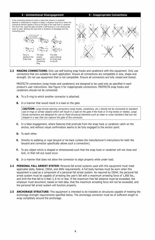
Connectors (hooks, carabiners, and D-rings) must be capable of supporting at least 5,000 lbs. (22.2 kN). Connectors must be compatible with the anchorage or other system components. Do not use equipment that is not compatible. Non-compatible connectors may unintentionally disengage. See Figure 4. Connectors must be compatible in size, shape, and strength. Self-locking snap hooks and carabiners are required by ANSI Z359.1, CSA Z259.12-11, and OSHA.
4
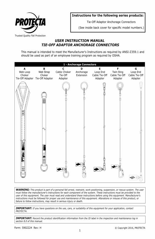
4 - Unintentional Disengagement 5 - Inappropriate Connections
If the connecting element to which a snap hook (shown) or carabiner attaches is undersized or irregular in shape, a situation could occur where the connecting element applies a force to the gate of the snap hook or carabiner. This force may cause the gate (of either a self-locking or a non-locking snap hook) to open, allowing the snap hook or carabiner to disengage from the connecting point.
Small ring or other non-compatibly shaped element
Force is applied to the Snap Hook.
The Gate presses against the Connecting Ring.
The Gate opens allowing the Snap Hook to slip off.
A. B. C. D.
E. F. G.
2.3 MAKING CONNECTIONS: Only use self-locking snap hooks and carabiners with this equipment. Only use connectors that are suitable to each application. Ensure all connections are compatible in size, shape and strength. Do not use equipment that is not compatible. Ensure all connectors are fully closed and locked.
PROTECTA connectors (snap hooks and carabiners) are designed to be used only as specifi ed in each product’s user instructions. See Figure 5 for inappropriate connections. PROTECTA snap hooks and carabiners should not be connected:
A. To a D-ring to which another connector is attached.
B. In a manner that would result in a load on the gate.
CAUTION: Large throat-opening connectors (snap hooks, carabiners, etc.) should not be connected to standard size D-rings or similar objects which will result in a load on the gate if the hook or D-ring twists or rotates. Large throat connectors are designed for use on fi xed structural elements such as rebar or cross members that are not shaped in a way that can capture the gate of the connector.
C. In a false engagement, where features that protrude from the snap hook or carabiner catch on the anchor, and without visual confirmation seems to be fully engaged to the anchor point.
D. To each other.
E. Directly to webbing or rope lanyard or tie-back (unless the manufacturer’s instructions for both the lanyard and connector specifically allows such a connection).
F. To any object which is shaped or dimensioned such that the snap hook or carabiner will not close and lock, or that roll-out could occur.
G. In a manner that does not allow the connector to align properly while under load.
2.4 PERSONAL FALL ARREST SYSTEM: Personal fall arrest systems used with this equipment must meet applicable state, federal, OSHA, and ANSI requirements. A full body harness must be worn when this equipment is used as a component of a personal fall arrest system. As required by OSHA, the personal fall arrest system must be capable of arresting the user’s fall with a maximum arresting force of 1,800 lbs., and limit the free fall to 6 feet (1.8 m) or less. If the maximum free fall distance must be exceeded, the employer must document, based on test data, that the maximum arresting force will not be exceeded, and the personal fall arrest system will function properly.
2.5 ANCHORAGE STRUCTURE: This equipment is intended to be installed on structures capable of meeting the anchorage strength requirements specifi ed below. The anchorage connector must be of suffi cient length to wrap completely around the anchorage.
5
2.6 ANCHORAGE STRENGTH: The anchorage strength required is dependent on the application. Following are anchorage strength requirements for specifi c applications:
A. FALL ARREST: The structure to which the anchorage connector is attached must sustain static loads applied in the directions permitted by the fall arrest system of at least: 3,600 lbs (16 kN) . with certification of a qualified person, or 5,000 lbs (22 kN). without certification. See ANSI Z359.1 for certification definition. When more than one personal fall arrest system is attached to an anchorage, the strengths stated above must be multiplied by the number of personal fall arrest systems attached to the anchorage.
FROM OSHA 1926.500 AND 1910.66: Anchorages used for attachment of a personal fall arrest system shall be independent of any anchorage being used to support or suspend platforms and must support at least 5,000 lbs (22 kN). per user attached; or be designed, installed, and used as part of a complete personal fall arrest system, which maintains a safety factor of at least two, and is supervised by a qualified person.
B. RESTRAINT: The structure to which the anchorage connector is attached must sustain static loads applied in the directions permitted by the restraint system of at least 3,000 lbs (13 kN). When more than one restraint system is attached to an anchorage, the strengths stated above must be multiplied by the number of restraint systems attached to the anchorage.
C. WORK POSITIONING: The structure to which the anchorage connector is attached must sustain static loads applied in the directions permitted by the work positioning system of at least 3,000 lbs. (13 kN), or twice the potential impact load, whichever is greater. When more than one work positioning system is attached to an anchorage, the strengths stated above must be multiplied by the number of work positioning systems attached to the anchorage.
D. PERSONNEL RIDING: The structure to which the anchorage connector is attached must sustain static loads applied in the directions permitted by the personnel riding system of at least 2,500 lbs (11 kN). When more than one personnel riding system is attached to an anchorage, the strengths stated above must be multiplied by the number of personnel riding systems attached to the anchorage.
E. RESCUE: The structure to which the anchorage connector is attached must sustain static loads applied in the directions permitted by the rescue system of at least 2,500 lbs (11 kN). When more than one rescue system is attached to an anchorage, the strengths stated above must be multiplied by the number of rescue systems attached to the anchorage.
3.0 INSTALLATION AND USE
WARNING: Do not alter or intentionally misuse this equipment; your safety may depend on it. Consult with PROTECTA if using this equipment with components or subsystems other than those described in this manual. Some subsystem and component combinations may interfere with the operation of this equipment.
WARNING: Consult with your doctor if you doubt your fi tness to safely absorb the shock from a fall arrest. Age and fi tness can seriously affect your ability to withstand falls. Pregnant women and minors must not use this equipment.
3.1 BEFORE EACH USE of this equipment, inspect it according to section 5.0 of this manual.
3.2 PLAN your system before installation. Consider all factors that will affect your safety during use of this equipment. The following list gives important points to consider when planning your system:
A. ANCHORAGE: Select an anchorage that meets the requirements specified in section 2.0.
B. SHARP EDGES: Avoid working where system components may be in contact with, or abrade against, unprotected sharp edges. Inspection frequency should be increased when an anchorage connector is installed around sharp edges.
C. AFTER A FALL: Components which have been subjected to the forces of arresting a fall must be removed from service and destroyed.
D. RESCUE: The employer must have a rescue plan when using this equipment. The employer must have the ability to perform a rescue quickly and safely.
6
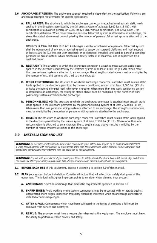
3.3 ANCHORAGE CONNECTOR INSTALLATION: (Refer to Figure 1 to identify models.)
WARNING: The "Choker" style tie-off adaptor anchorage connectors must be tight against the anchoring structure. Do not leave slack in the anchorage connector, this may increase the free fall distance in the event of a fall.
Do not leave slack in the anchorage connector
A. ANCHORAGE CONNECTOR LOCATION: Select an anchorage location with minimal free fall and swing fall hazards (see Section 1.2). Select a rigid anchorage point capable of sustaining the static loads defined in Section 2.6.
B. STRUCTURE: The structure to which the anchorage connector is attached must be free of corrosion, cracks, deformities, or other defects that may weaken the structure. Do not attach an anchorage connector to a vertical structure unless a means of restraining the connector from sliding down the structure is present. If the anchorage connector were to slide down the structure in a fall arrest situation, serious injury to the user is possible.
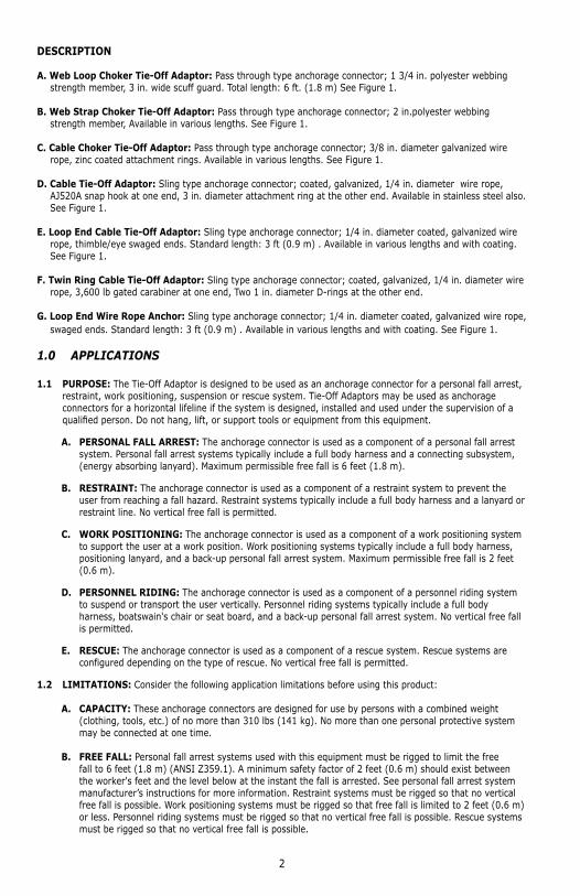
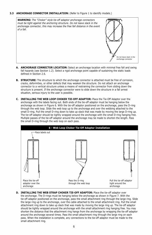
C. INSTALLING THE WEB LOOP CHOKER TIE-OFF ADAPTOR: Place the Tie-Off Adaptor over the anchorage with the labels facing out. Both ends of the tie-off adaptor must be hanging below the anchorage as shown in Figure 6. With the tie-off adaptor positioned on the anchorage, pass the D-ring through the web loop. Slide the web loop up to the anchorage and over the webbing attached to the small D-ring. Pull the small D-ring down to take up slack that was made by moving the large D-ring up. The tie-off adaptor should be tightly wrapped around the anchorage with the small D-ring hanging free. Multiple passes of the tie-off adaptor around the anchorage may be made to shorten the length. Pass the small D-ring through the web loop on each pass.
6 - Web Loop Choker Tie-Off Adaptor Installation
Place the tie-off adaptor over the anchorage
Pass the D-ring through the web loop
Pull the tie-off adaptor tight around the anchorage
Face labels out
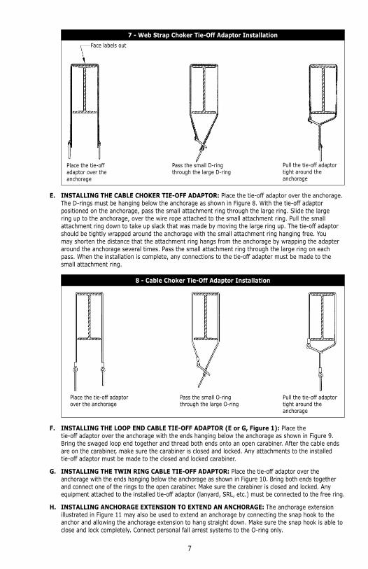
D. INSTALLING THE WEB STRAP CHOKER TIE-OFF ADAPTOR: Place the tie-off adaptor over the anchorage. The D-rings must be hanging below the anchorage as shown in Figure 7. With the tie-off adaptor positioned on the anchorage, pass the small attachment ring through the large ring. Slide the large ring up to the anchorage, over the cable attached to the small attachment ring. Pull the small attachment ring down to take up slack that was made by moving the large ring up. The tie-off adaptor should be tightly wrapped around the anchorage with the small attachment ring hanging free. You may shorten the distance that the attachment ring hangs from the anchorage by wrapping the tie-off adaptor around the anchorage several times. Pass the small attachment ring through the large ring on each pass. When the installation is complete, any connections to the tie-off adaptor must be made to the small attachment ring.
7
7 - Web Strap Choker Tie-Off Adaptor Installation
Pull the tie-off adaptor tight around the anchorage
Pass the small D-ring through the large D-ring
Place the tie-off adaptor over the anchorage
Face labels out
E. INSTALLING THE CABLE CHOKER TIE-OFF ADAPTOR: Place the tie-off adaptor over the anchorage. The D-rings must be hanging below the anchorage as shown in Figure 8. With the tie-off adaptor positioned on the anchorage, pass the small attachment ring through the large ring. Slide the large ring up to the anchorage, over the wire rope attached to the small attachment ring. Pull the small attachment ring down to take up slack that was made by moving the large ring up. The tie-off adaptor should be tightly wrapped around the anchorage with the small attachment ring hanging free. You may shorten the distance that the attachment ring hangs from the anchorage by wrapping the adapter around the anchorage several times. Pass the small attachment ring through the large ring on each pass. When the installation is complete, any connections to the tie-off adapter must be made to the small attachment ring.
8 - Cable Choker Tie-Off Adaptor Installation
Place the tie-off adaptor over the anchorage
Pass the small O-ring through the large O-ring
Pull the tie-off adaptor tight around the anchorage
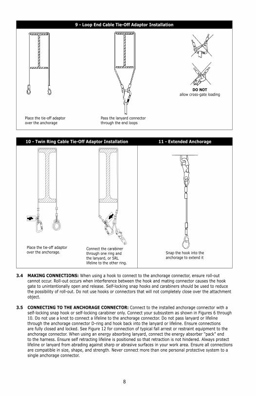
F. INSTALLING THE LOOP END CABLE TIE-OFF ADAPTOR (E or G, Figure 1): Place the tie-off adaptor over the anchorage with the ends hanging below the anchorage as shown in Figure 9. Bring the swaged loop end together and thread both ends onto an open carabiner. After the cable ends are on the carabiner, make sure the carabiner is closed and locked. Any attachments to the installed tie-off adaptor must be made to the closed and locked carabiner.
G. INSTALLING THE TWIN RING CABLE TIE-OFF ADAPTOR: Place the tie-off adaptor over the anchorage with the ends hanging below the anchorage as shown in Figure 10. Bring both ends together and connect one of the rings to the open carabiner. Make sure the carabiner is closed and locked. Any equipment attached to the installed tie-off adaptor (lanyard, SRL, etc.) must be connected to the free ring.
H. INSTALLING ANCHORAGE EXTENSION TO EXTEND AN ANCHORAGE: The anchorage extension illustrated in Figure 11 may also be used to extend an anchorage by connecting the snap hook to the anchor and allowing the anchorage extension to hang straight down. Make sure the snap hook is able to close and lock completely. Connect personal fall arrest systems to the O-ring only.
8
9 - Loop End Cable Tie-Off Adaptor Installation
Place the tie-off adaptor over the anchorage
Pass the lanyard connector through the end loops
DO NOTallow cross-gate loading
10 - Twin Ring Cable Tie-Off Adaptor Installation 11 - Extended Anchorage
Place the tie-off adaptor over the anchorage.
Connect the carabiner through one ring and the lanyard, or SRL lifeline to the other ring.
Snap the hook into the anchorage to extend it
3.4 MAKING CONNECTIONS: When using a hook to connect to the anchorage connector, ensure roll-out cannot occur. Roll-out occurs when interference between the hook and mating connector causes the hook gate to unintentionally open and release. Self-locking snap hooks and carabiners should be used to reduce the possibility of roll-out. Do not use hooks or connectors that will not completely close over the attachment object.
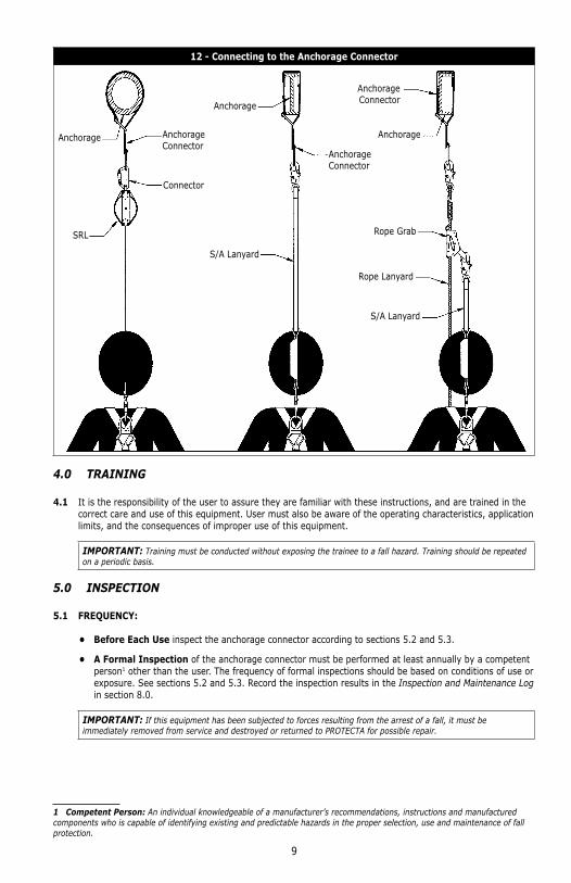
3.5 CONNECTING TO THE ANCHORAGE CONNECTOR: Connect to the installed anchorage connector with a self-locking snap hook or self-locking carabiner only. Connect your subsystem as shown in Figures 6 through 10. Do not use a knot to connect a lifeline to the anchorage connector. Do not pass lanyard or lifeline through the anchorage connector D-ring and hook back into the lanyard or lifeline. Ensure connections are fully closed and locked. See Figure 12 for connection of typical fall arrest or restraint equipment to the anchorage connector. When using an energy absorbing lanyard, connect the energy absorber "pack" end to the harness. Ensure self retracting lifeline is positioned so that retraction is not hindered. Always protect lifeline or lanyard from abrading against sharp or abrasive surfaces in your work area. Ensure all connections are compatible in size, shape, and strength. Never connect more than one personal protective system to a single anchorage connector.
9
12 - Connecting to the Anchorage Connector
Anchorage
Anchorage
AnchorageAnchorage Connector
Anchorage Connector
Anchorage Connector
Connector
SRL
S/A Lanyard
S/A Lanyard
Rope Grab
Rope Lanyard
4.0 TRAINING
4.1 It is the responsibility of the user to assure they are familiar with these instructions, and are trained in the correct care and use of this equipment. User must also be aware of the operating characteristics, application limits, and the consequences of improper use of this equipment.
IMPORTANT: Training must be conducted without exposing the trainee to a fall hazard. Training should be repeated on a periodic basis.
5.0 INSPECTION
5.1 FREQUENCY:
• Before Each Use inspect the anchorage connector according to sections 5.2 and 5.3.
• A Formal Inspection of the anchorage connector must be performed at least annually by a competent person1 other than the user. The frequency of formal inspections should be based on conditions of use or exposure. See sections 5.2 and 5.3. Record the inspection results in the Inspection and Maintenance Log in section 8.0.
IMPORTANT: If this equipment has been subjected to forces resulting from the arrest of a fall, it must be immediately removed from service and destroyed or returned to PROTECTA for possible repair.
1 Competent Person: An individual knowledgeable of a manufacturer’s recommendations, instructions and manufactured components who is capable of identifying existing and predictable hazards in the proper selection, use and maintenance of fall protection.
10
5.2 INSPECTION STEPS:
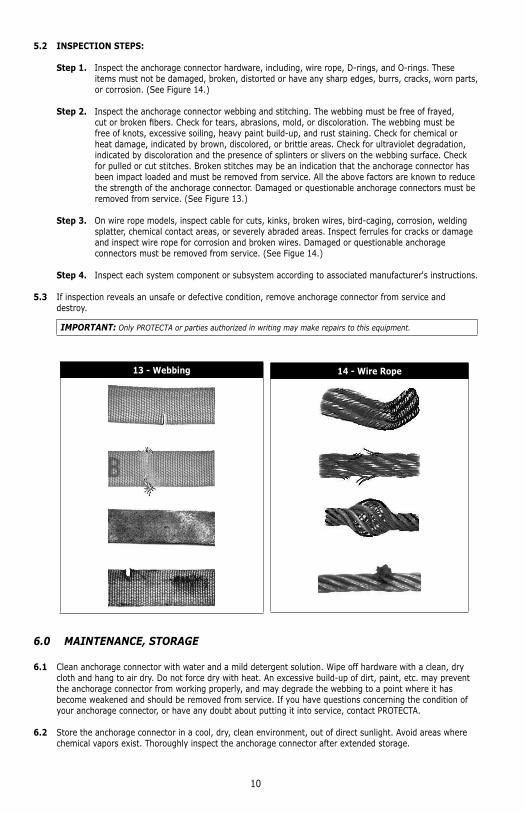
Step 1. Inspect the anchorage connector hardware, including, wire rope, D-rings, and O-rings. These items must not be damaged, broken, distorted or have any sharp edges, burrs, cracks, worn parts, or corrosion. (See Figure 14.)
Step 2. Inspect the anchorage connector webbing and stitching. The webbing must be free of frayed, cut or broken fi bers. Check for tears, abrasions, mold, or discoloration. The webbing must be free of knots, excessive soiling, heavy paint build-up, and rust staining. Check for chemical or heat damage, indicated by brown, discolored, or brittle areas. Check for ultraviolet degradation, indicated by discoloration and the presence of splinters or slivers on the webbing surface. Check for pulled or cut stitches. Broken stitches may be an indication that the anchorage connector has been impact loaded and must be removed from service. All the above factors are known to reduce the strength of the anchorage connector. Damaged or questionable anchorage connectors must be removed from service. (See Figure 13.)
Step 3. On wire rope models, inspect cable for cuts, kinks, broken wires, bird-caging, corrosion, welding splatter, chemical contact areas, or severely abraded areas. Inspect ferrules for cracks or damage and inspect wire rope for corrosion and broken wires. Damaged or questionable anchorage connectors must be removed from service. (See Figue 14.)
Step 4. Inspect each system component or subsystem according to associated manufacturer's instructions.
5.3 If inspection reveals an unsafe or defective condition, remove anchorage connector from service and destroy.
IMPORTANT: Only PROTECTA or parties authorized in writing may make repairs to this equipment.
13 - Webbing 14 - Wire Rope
6.0 MAINTENANCE, STORAGE
6.1 Clean anchorage connector with water and a mild detergent solution. Wipe off hardware with a clean, dry cloth and hang to air dry. Do not force dry with heat. An excessive build-up of dirt, paint, etc. may prevent the anchorage connector from working properly, and may degrade the webbing to a point where it has become weakened and should be removed from service. If you have questions concerning the condition of your anchorage connector, or have any doubt about putting it into service, contact PROTECTA.
6.2 Store the anchorage connector in a cool, dry, clean environment, out of direct sunlight. Avoid areas where chemical vapors exist. Thoroughly inspect the anchorage connector after extended storage.
11
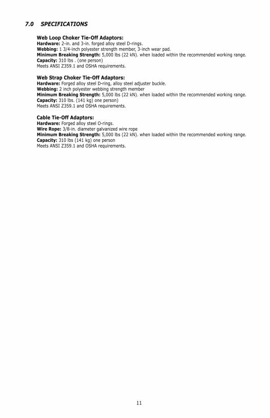
7.0 SPECIFICATIONS
Web Loop Choker Tie-Off Adaptors: Hardware: 2-in. and 3-in. forged alloy steel D-rings. Webbing: 1 3/4-inch polyester strength member, 3-inch wear pad. Minimum Breaking Strength: 5,000 lbs (22 kN). when loaded within the recommended working range. Capacity: 310 lbs . (one person) Meets ANSI Z359.1 and OSHA requirements.
Web Strap Choker Tie-Off Adaptors: Hardware: Forged alloy steel D-ring, alloy steel adjuster buckle. Webbing: 2 inch polyester webbing strength member Minimum Breaking Strength: 5,000 lbs (22 kN). when loaded within the recommended working range. Capacity: 310 lbs. (141 kg) one person) Meets ANSI Z359.1 and OSHA requirements.
Cable Tie-Off Adaptors: Hardware: Forged alloy steel O-rings. Wire Rope: 3/8-in. diameter galvanized wire rope Minimum Breaking Strength: 5,000 lbs (22 kN). when loaded within the recommended working range. Capacity: 310 lbs (141 kg) one person Meets ANSI Z359.1 and OSHA requirements.

12
8.0 INSPECTION AND MAINTENANCE LOG
SERIAL NUMBER:
MODEL NUMBER:
DATE PURCHASED: DATE OF FIRST USE:
INSPECTION DATE INSPECTION ITEMS NOTED
CORRECTIVE ACTION MAINTENANCE PERFORMED
Approved By:
Approved By:
Approved By:
Approved By:
Approved By:
Approved By:
Approved By:
Approved By:
Approved By:
Approved By:
Approved By:
Approved By:
Approved By:
Approved By:
Approved By:
Approved By:
Approved By:
Approved By:
Approved By:
13
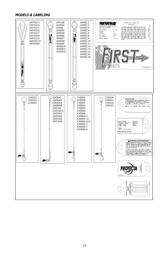
MODELS & LABELING
AJ47410-3AJ47410-4AJ47410-5AJ47410-6AJ47410-7AJ47410-8AJ47410-9AJ47410-10AJ47410A3
AJ451A6AJ450A2AJ450AAJ450A4AJ450A5AJ450A6AJ450A7AJ450A8AJ450A9AJ450A10AJ450A12AJ450A15
AJ450C-2AJ450C-3AJ450C-4AJ450C-5AJ450C-6AJ450C-8AJ450C-9AJ450C-10AJ450C-11AJ450C-12AJ450C-13AJ450C-14AJ450C-22AJ450C-35
210019221001932199900
AJ406AGAJ406AG4AJ406AG5AJ406AG8AJ407AGAJ407AG10AJ407AG3AJ407AG4AJ407AG5AJ407AG8
219993621999382199943219995221999542199955AJ408AGAJ408AG-2AJ408AG-10AJ408AG-14.5AJ408AG-3AJ408AG-4AJ408AG-8
2190100219010121901022190103
WARNING/AVERTISSEMENT!
14
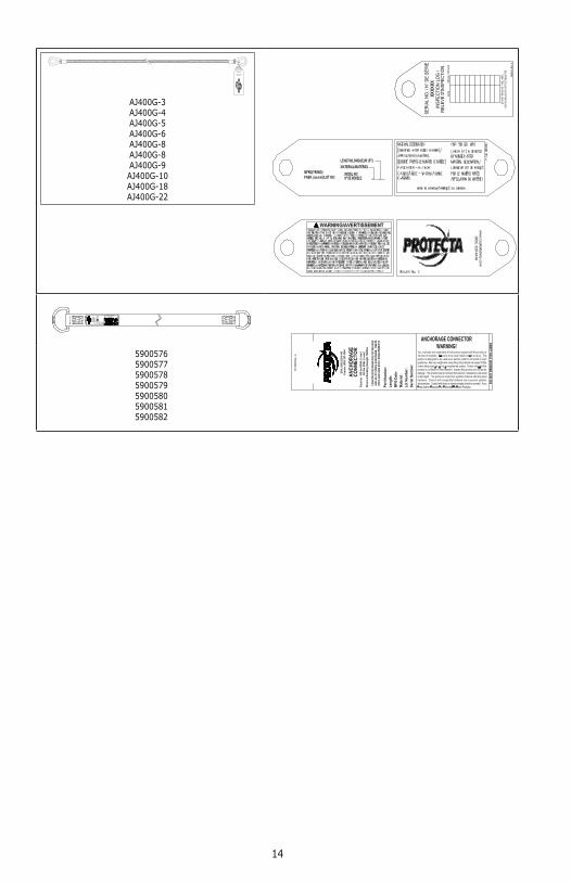
AJ400G-3AJ400G-4AJ400G-5AJ400G-6AJ400G-8AJ400G-8AJ400G-9AJ400G-10AJ400G-18AJ400G-22
5900576590057759005785900579590058059005815900582
LIMITED LIFETIME WARRANTYWarranty to End User: D B Industries, LLC dba CAPITAL SAFETY USA (“CAPITAL SAFETY”) warrants to the original end user (“End User”) that its products are free from defects in materials and workmanship under normal use and service. This warranty extends for the lifetime of the product from the date the product is purchased by the End User, in new and unused condition, from a CAPITAL SAFETY authorized distributor. CAPITAL SAFETY’S entire liability to End User and End User’s exclusive remedy under this warranty is limited to the repair or replacement in kind of any defective product within its lifetime (as CAPITAL SAFETY in its sole discretion determines and deems appropriate). No oral or written information or advice given by CAPITAL SAFETY, its distributors, directors, offi cers, agents or employees shall create any different or additional warranties or in any way increase the scope of this warranty. CAPITAL SAFETY will not accept liability for defects that are the result of product abuse, misuse, alteration or modifi cation, or for defects that are due to a failure to install, maintain, or use the product in accordance with the manufacturer’s instructions.
CAPITAL SAFETY’S WARRANTY APPLIES ONLY TO THE END USER. THIS WARRANTY IS THE ONLY WARRANTY APPLICABLE TO OUR PRODUCTS AND IS IN LIEU OF ALL OTHER WARRANTIES AND LIABILITIES, EXPRESSED OR IMPLIED. CAPITAL SAFETY EXPRESSLY EXCLUDES AND DISCLAIMS ANY IMPLIED WARRANTIES OF MERCHANTABILITY OR FITNESS FOR A PARTICULAR PURPOSE, AND SHALL NOT BE LIABLE FOR INCIDENTAL, PUNITIVE OR CONSEQUENTIAL DAMAGES OF ANY NATURE, INCLUDING WITHOUT LIMITATION, LOST PROFITS, REVENUES, OR PRODUCTIVITY, OR FOR BODILY INJURY OR DEATH OR LOSS OR DAMAGE TO PROPERTY, UNDER ANY THEORY OF LIABILITY, INCLUDING WITHOUT LIMITATION, CONTRACT, WARRANTY, STRICT LIABILITY, TORT (INCLUDING NEGLIGENCE) OR OTHER LEGAL OR EQUITABLE THEORY.
GARANTÍA LIMITADA DE POR VIDAGarantía para el usuario fi nal: D B Industries, LLC, que opera bajo el nombre de CAPITAL SAFETY USA (“CAPITAL SAFETY”) garantiza al usuario fi nal original (“Usuario fi nal”) que sus productos están libres de defectos de materiales y de mano de obra en condiciones normales de uso y mantenimiento. Esta garantía se extiende durante la vida útil del producto a partir de la fecha en que el Usuario fi nal adquiere el producto, nuevo y sin uso, a un distribuidor autorizado de CAPITAL SAFETY. La entera responsabilidad de CAPITAL SAFETY hacia el Usuario fi nal y el remedio exclusivo para el Usuario fi nal bajo esta garantía están limitados a la reparación o el reemplazo por materiales de todo producto defectuoso dentro de su vida útil (según CAPITAL SAFETY lo determine y considere apropiado a su solo criterio). Ninguna información o asesoramiento, oral o escrito, proporcionado por CAPITAL SAFETY, sus distribuidores, directores, funcionarios, agentes o empleados creará una garantía diferente o adicional ni aumentará de ninguna manera el alcance de esta garantía. CAPITAL SAFETY no aceptará responsabilidad por defectos resultantes del abuso, el uso incorrecto, la alteración o la modifi cación del producto, ni por defectos resultantes de no respetar las instrucciones del fabricante durante la instalación, el mantenimiento o el uso del producto.
LA GARANTÍA DE CAPITAL SAFETY SE APLICA ÚNICAMENTE AL USUARIO FINAL. ESTA GARANTÍA ES LA ÚNICA GARANTÍA QUE SE APLICA A NUESTROS PRODUCTOS Y REEMPLAZA A TODAS LAS OTRAS GARANTÍAS Y RESPONSABILIDADES, EXPRESAS O IMPLÍCITAS. CAPITAL SAFETY EXPRESAMENTE EXCLUYE Y RENUNCIA A TODAS LAS GARANTÍAS IMPLÍCITAS DE COMERCIABILIDAD O APTITUD PARA UN PROPÓSITO PARTICULAR, Y NO SERÁ RESPONSABLE POR DAÑOS INCIDENTALES, PUNITIVOS O EMERGENTES DE NINGUNA NATURALEZA, INCLUYENDO SIN LIMITACIÓN PÉRDIDAS DE INGRESOS, GANANCIAS O PRODUCTIVIDAD; NI POR LESIONES CORPORALES O MUERTE, O PÉRDIDA DE O DAÑO A LA PROPIEDAD, BAJO CUALQUIER TEORÍA DE RESPONSABILIDAD, INCLUYENDO SIN LIMITACIÓN CONTRATO, GARANTÍA, RESPONSABILIDAD ESTRICTA, AGRAVIO (INCLUIDA NEGLIGENCIA) O CUALQUIER OTRA TEORÍA LEGAL O EQUITATIVA.
GARANTIE LIMITÉE SUR LA DURÉE DE VIEGarantie offerte à l’utilisateur fi nal : D B Industries, LLC dba CAPITAL SAFETY USA (« CAPITAL SAFETY ») garantit à l’utilisateur fi nal d’origine (« Utilisateur fi nal ») que les produits sont libres de tout défaut matériel et de fabrication dans des conditions normales d’utilisation et de service. Cette garantie couvre toute la durée de vie du produit, de sa date d’achat à l’état neuf et inutilisé par l’utilisateur auprès d’un distributeur agréé CAPITAL SAFETY. La responsabilité intégrale de Capital Safety et le seul recours du Client dans le cadre de cette garantie se limitent à la réparation ou le remplacement en nature des produits défectueux pendant leur durée de vie (à la seule discrétion de Capital Safety et selon ce qu’elle juge approprié). Aucun renseignement ou avis oral ou écrit fourni par CAPITAL SAFETY, ses détaillants, administrateurs, cadres, distributeurs, mandataires ou employés ne représentera une garantie ou n’augmentera de quelque manière la portée de la présente garantie limitée. CAPITAL SAFETY n’accepte aucune responsabilité pour les défauts causés par un abus, une utilisation abusive, une altération ou une modifi cation, ou pour les défauts causés par le non-respect des instructions du fabricant relatives à l’installation, à l’entretien ou à l’utilisation du produit.
CETTE GARANTIE CAPITAL SAFETY S’APPLIQUE UNIQUEMENT À L’UTILISATEUR FINAL. ELLE EST LA SEULE GARANTIE APPLICABLE À NOS PRODUITS. ELLE EXCLUT TOUTE AUTRE GARANTIE EXPRESSE OU IMPLICITE. CAPITAL SAFETY EXCLUT EXPLICITEMENT ET DÉCLINE TOUTE GARANTIE IMPLICITE DE MISE EN MARCHÉ ET D’ADAPTATION À DES FINS PARTICULIÈRES, ET NE SERA RESPONSABLE POUR AUCUN DOMMAGE-INTÉRÊT DIRECT OU INDIRECT, CORRÉLATIF OU ACCESSOIRE DE TOUTE NATURE Y COMPRIS ET DE MANIÈRE NON LIMITATIVE, LES PERTES DE PROFITS, LES REVENUS OU LA PRODUCTIVITÉ, LES BLESSURES CORPORELLES, VOIRE LA MORT OU DOMMAGES À LA PROPRIÉTÉ, DANS LE CADRE DE TOUTE THÉORIE DE RESPONSABILITÉ, Y COMPRIS ET DE MANIÈRE NON LIMITATIVE UN CONTRAT, UNE GARANTIE, UNE RESPONSABILITÉ (Y COMPRIS LA NÉGLIGENCE) OU TOUTE AUTRE THÉORIE LÉGALE OU ÉQUITABLE.

I S O9001
USA3833 SALA Way Red Wing, MN 55066-5005 Toll Free: 800.328.6146Phone: 651.388.8282Fax: [email protected]
BrazilRua Anne Frank, 2621Boqueirão Curitiba PR81650-020BrazilPhone: [email protected]
MexicoCalle Norte 35, 895-ECol. Industrial VallejoC.P. 02300 AzcapotzalcoMexico D.F.Phone: (55) [email protected]
ColombiaCompañía Latinoamericana de Seguridad S.A.S.Carrera 106 #15-25 Interior 105 Manzana 15Zona Franca - Bogotá, ColombiaPhone: 57 1 [email protected]
Canada260 Export Boulevard Mississauga, ON L5S 1Y9 Phone: 905.795.9333 Toll-Free: 800.387.7484 Fax: 888.387.7484 [email protected]
EMEA (Europe, Middle East, Africa)EMEA Headquarters:5a Merse RoadNorth Moons MoatRedditch, WorcestershireB98 9HL UKPhone: + 44 (0)1527 548 000Fax: + 44 (0)1527 591 [email protected]
France:Le Broc CenterZ.I. 1re Avenue - BP1506511 Carros Le Broc CedexFrancePhone: + 33 04 97 10 00 10Fax: + 33 04 93 08 79 [email protected]
Australia & New Zealand95 Derby StreetSilverwaterSydney NSW 2128AustraliaPhone: +(61) 2 8753 7600Toll-Free : 1800 245 002 (AUS)Toll-Free : 0800 212 505 (NZ) Fax: +(61) 2 8753 7603 [email protected]
AsiaSingapore:69, Ubi Road 1, #05-20 Oxley BizhubSingapore 408731Phone: +65 - 65587758Fax: +65 - [email protected]
Shanghai:Rm 1406, China Venturetech Plaza819 Nan Jing Xi Rd,Shanghai 200041, P R ChinaPhone: +86 21 62539050Fax: +86 21 [email protected]
www.capitalsafety.com