Embed Size (px)
Citation preview
Bulletin9E 1/08
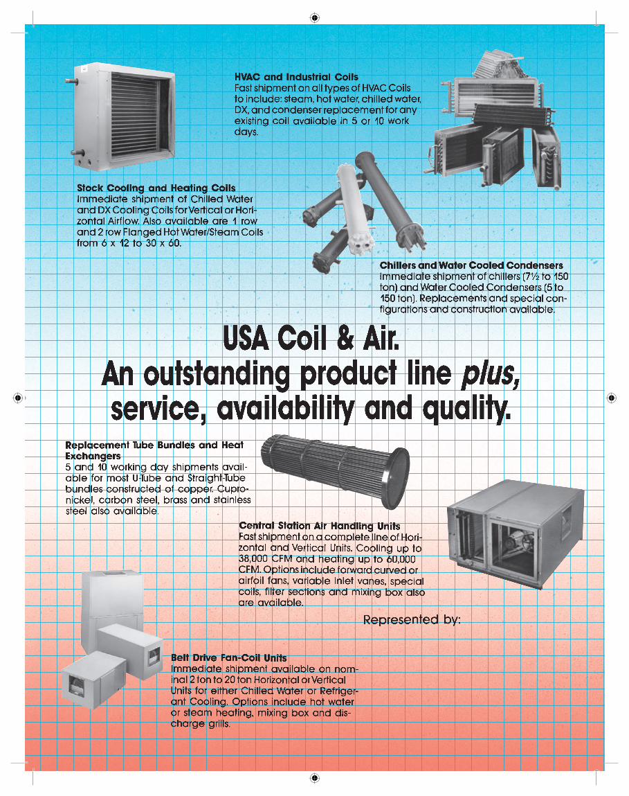
Central StationAir Handlers
Indoor & Outdoor
2
Custom & ReplacementAir Handling Units
Unique Replacement Engineeringand quality design
creates the perfect fit.Design/Build Specialists
USA Coil & Air has been an industry leader in buildingair handlers for both new and replacement applications fordecades. We bring all the newest technology to both thedesign and performance of our central station air handlingunits, and we offer extensive experience in design-buildand retrofit applications.
USA builds units that are a cross between standard airhandlers and custom units. We offer all kinds of optionsand accessories that allow you to semi-customize yourunit. You can vary dimensions, add special sections, usepainted or galvanized sections, and just generally designthe unit that you need for your job. And the best part is thatyou’re not paying for a total custom unit. You’re gettingmost of what you want at “standard unit” prices.
USA can tailor our selection to meet your requirements.Our software is designed to offer you the equivalent of acomplete submittal at the time of our proposal to you. Youwill get complete performance, dimensions and choices inoptions and accessories. You will have a menu to choosefrom, so that you can design the unit that fits your spaceand meets your requirements for your specific job.
Also, many existing units fail to meet revised conditionsor systematic conditions that might mean that you requirenew units to do your job. USA has a wealth of experiencein retrofit/replacement and nobody can do a better job ofwalking you through the design of your new unit. We offersuggestions and engineering recommendations that cre-ate better performance, higher efficiency and longevity. Callus and we will be happy to work with you on your nextproject.
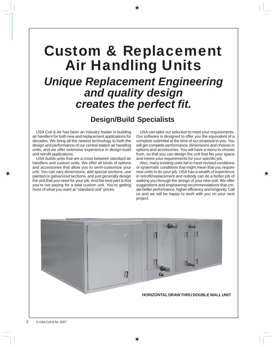
HORIZONTAL DRAW THRU DOUBLE WALL UNIT
© USA Coil & Air, 2007
3
• Access Panels and Doors strategically located toallow for proper service and maintenance of unitary com-ponents.
• Extended Fan Bearing Lube Lines and Coil Con-nections to easily maintain drain lines and keep air mov-ing equipment lubricated.
Flexible Design• Modular Design that allows you to mix and match
sections to essentially build an air handler your way!• Flexible Dimensioning gives you the ability to de-
sign a unit and its components in a box size that meetsthe dimensional criteria of the installation.
• Indoor and Outdoor Construction available. If it ison a platform, pad, steel or a curb, then we have a unit tomeet your exacting design.
Simple, Low Cost Installation• Bolted Frame Construction with easy to remove pan-
els• Simple Section Attachment via patented splicing
design• Gasketed Extended Coil Connections and Drain
Pan Connections that eliminate constant panel remov-able and guaranteed air tight unit.
Operating Efficiency• Computer selected Components provide the high-
est efficiency at a reasonable first cost basis.• Solid or Perforated Double Wall Liners reduce con-
densation and air leakage• Double wall injected foam insulation increases
panel strength and R-value of R-13
Easy Service and Maintenance• Special Access Sections can be located between
any system components allowing walk in space or changeany item.
• Low Leak Cabinet Design means you’re providingheated or cooled air to the intended space and not to aremote area.
• Low Leak Dampers reduce operating costs and sim-plify installation.
• Huge Offering of Adaptable Inlet and Outlet Sec-tions that minimize the attachment of ductwork and re-duces labor costs
• Complete Drive Side Assembly to include customfan, motor drive and vibration isolation mounted and fac-tory tested on a unit mounted steel base.
• Galvanized Steel Cabinets or Painted Steel whichoffers a quality option if a smooth appearance is required.
• Ship Assembled or In Sections gives the installerthe ability to move units into place quickly and efficiently.Special design is always a possibility to move units throughbuilding openings to include fresh air, doorways, elevatorsand stairs. In really tight areas, each section can be to-tally knocked down and reassembled on site.
Expedited Shipping SchedulesMany projects require some form of quick shipment when
you need units for design-build or units for replacement.Quick shipment is often your first thought. “How do I getthe units on the job quickly?”
USA offers quick ships on many of our units. Often weship central stations within a month. We can’t offer every
option or accessory under this program, because that justwouldn’t be practical. We can’t always do it, just based onscheduling and backlog. USA, however, does a great jobof shipping quick when it’s possible. If we can help yousolve your problem with our quick ship program, then wewill.
4
General Features - Indoor Units
QualityFor many years USA Coil & Air has been respected and
highly regarded for their fast shipment of high quality air han-dling equipment. USA has taken a major step forward in re-defining the indoor central station air handler. Demands forimproved indoor air quality, low sound, high operating effi-ciency and smaller mechanical rooms require a better prod-uct for today’s air handler market. The USA Indoor CentralStation air handler has been designed to meet or exceedthese demands.
The key to providing such a high quality product is in thebasic design. The USA Indoor Central Station’s unique con-struction has been designed to provide unequaled thermalefficiencies and to be airtight. In addition, USA Indoor AirHandlers offer tremendous flexibility in sizing, componentoptions and unit arrangements to meet the indoor air qualityrequirements, operating efficiency, sound and installationrequirements for today’s extensive commercial and custommarkets.
FlexibilityBy virtue of its unique frame design, the USA Indoor Air
Handler offers incredible flexibility. This is reflected in ourVariable Increment feature that allows USA air handlers tobe sized in two-inch increments (height and width) to fit theavailable space. Numerous section and component options,and the ability to arrange components in whatever arrange-
ment required, allow USA air handlers to be customized tothe requirements of each job without expensive field modifi-cations. Finally, USA air handlers can be shipped as a com-pletely assembled unit, in modules or by component sec-tions for new or retrofit applications that require smaller sec-tions for passage through the building.
Cabinet ConstructionUSA Indoor Air Handler cabinetry consists of a box-type
frame channel - the backbone of the unit - and easy-to-re-move panels or hinged access doors. The unique, patentedframe channel design allows three identical pieces to be boltedtogether to form a corner of the unit. Channels are formed ofG90 galvanized steel or G60 painted galvanized with factoryapplied neoprene gasketing on all flanges to minimize ther-mal leakage. Gasketing is also factory applied at all contactsurfaces between interior and exterior metal components tominimize thermal bridging. Panels are secured to the unit
with fasteners that can be easily removed to access the unitinterior. The frame channel and panels can be easily disas-sembled and reassembled, giving contractors tremendousflexibility in installing and servicing the units - even wherespace is very limited - saving time and money. Patentedsplice joints help guide sections together for a tight fit, sav-ing additional time and money on installation. Splice jointsare also fully insulated at the factory.
Access and ServiceabilityEquipment must be designed to perform efficiently and
withstand the wear and tear of everyday use. It must also bedesigned to provide easy access to interior components forroutine maintenance and service to maintain peak perfor-mance. Special frame channels and easy-to-remove panelsor hinged access doors of the USA Indoor Air Handler cabi-net provide complete access to the unit interior and compo-
nents. These components, including the fan and coil as-sembly, can be removed through the side of the unit, top ofthe unit, or a combination of both, which reduces requiredservice clearances. Coil removal on unstacked coils doesnot require access to the non-connection end of the coil. Aunique coil tie down method simplifies coil removal and re-placement.
5
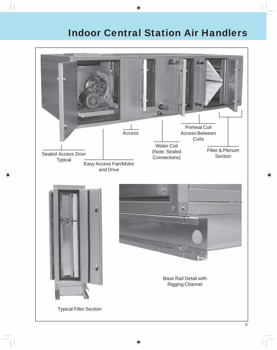
Typical Filter Section
Base Rail Detail withRigging Channel
Indoor Central Station Air Handlers
Sealed Access DoorTypical
Easy Access Fan/Motorand Drive
Access
Water Coil(Note: SealedConnections)
Preheat CoilAccess Between
Coils
Filter & PlenumSection
6
General Features - Outdoor Units
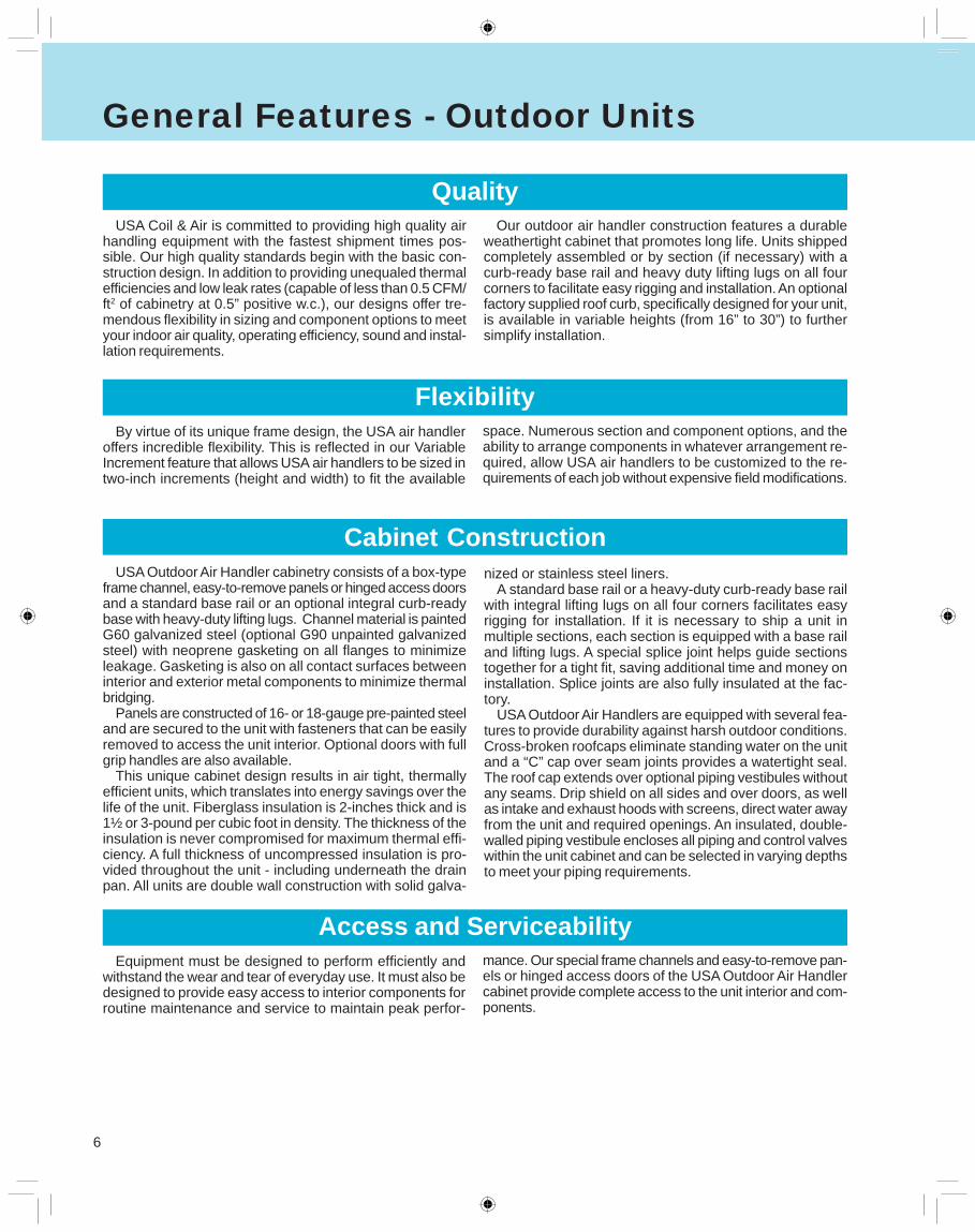
QualityUSA Coil & Air is committed to providing high quality air
handling equipment with the fastest shipment times pos-sible. Our high quality standards begin with the basic con-struction design. In addition to providing unequaled thermalefficiencies and low leak rates (capable of less than 0.5 CFM/ft2 of cabinetry at 0.5” positive w.c.), our designs offer tre-mendous flexibility in sizing and component options to meetyour indoor air quality, operating efficiency, sound and instal-lation requirements.
FlexibilityBy virtue of its unique frame design, the USA air handler
offers incredible flexibility. This is reflected in our VariableIncrement feature that allows USA air handlers to be sized intwo-inch increments (height and width) to fit the available
space. Numerous section and component options, and theability to arrange components in whatever arrangement re-quired, allow USA air handlers to be customized to the re-quirements of each job without expensive field modifications.
Cabinet ConstructionUSA Outdoor Air Handler cabinetry consists of a box-type
frame channel, easy-to-remove panels or hinged access doorsand a standard base rail or an optional integral curb-readybase with heavy-duty lifting lugs. Channel material is paintedG60 galvanized steel (optional G90 unpainted galvanizedsteel) with neoprene gasketing on all flanges to minimizeleakage. Gasketing is also on all contact surfaces betweeninterior and exterior metal components to minimize thermalbridging.
Panels are constructed of 16- or 18-gauge pre-painted steeland are secured to the unit with fasteners that can be easilyremoved to access the unit interior. Optional doors with fullgrip handles are also available.
This unique cabinet design results in air tight, thermallyefficient units, which translates into energy savings over thelife of the unit. Fiberglass insulation is 2-inches thick and is1½ or 3-pound per cubic foot in density. The thickness of theinsulation is never compromised for maximum thermal effi-ciency. A full thickness of uncompressed insulation is pro-vided throughout the unit - including underneath the drainpan. All units are double wall construction with solid galva-
Access and ServiceabilityEquipment must be designed to perform efficiently and
withstand the wear and tear of everyday use. It must also bedesigned to provide easy access to interior components forroutine maintenance and service to maintain peak perfor-
mance. Our special frame channels and easy-to-remove pan-els or hinged access doors of the USA Outdoor Air Handlercabinet provide complete access to the unit interior and com-ponents.
Our outdoor air handler construction features a durableweathertight cabinet that promotes long life. Units shippedcompletely assembled or by section (if necessary) with acurb-ready base rail and heavy duty lifting lugs on all fourcorners to facilitate easy rigging and installation. An optionalfactory supplied roof curb, specifically designed for your unit,is available in variable heights (from 16” to 30”) to furthersimplify installation.
nized or stainless steel liners.A standard base rail or a heavy-duty curb-ready base rail
with integral lifting lugs on all four corners facilitates easyrigging for installation. If it is necessary to ship a unit inmultiple sections, each section is equipped with a base railand lifting lugs. A special splice joint helps guide sectionstogether for a tight fit, saving additional time and money oninstallation. Splice joints are also fully insulated at the fac-tory.
USA Outdoor Air Handlers are equipped with several fea-tures to provide durability against harsh outdoor conditions.Cross-broken roofcaps eliminate standing water on the unitand a “C” cap over seam joints provides a watertight seal.The roof cap extends over optional piping vestibules withoutany seams. Drip shield on all sides and over doors, as wellas intake and exhaust hoods with screens, direct water awayfrom the unit and required openings. An insulated, double-walled piping vestibule encloses all piping and control valveswithin the unit cabinet and can be selected in varying depthsto meet your piping requirements.
7
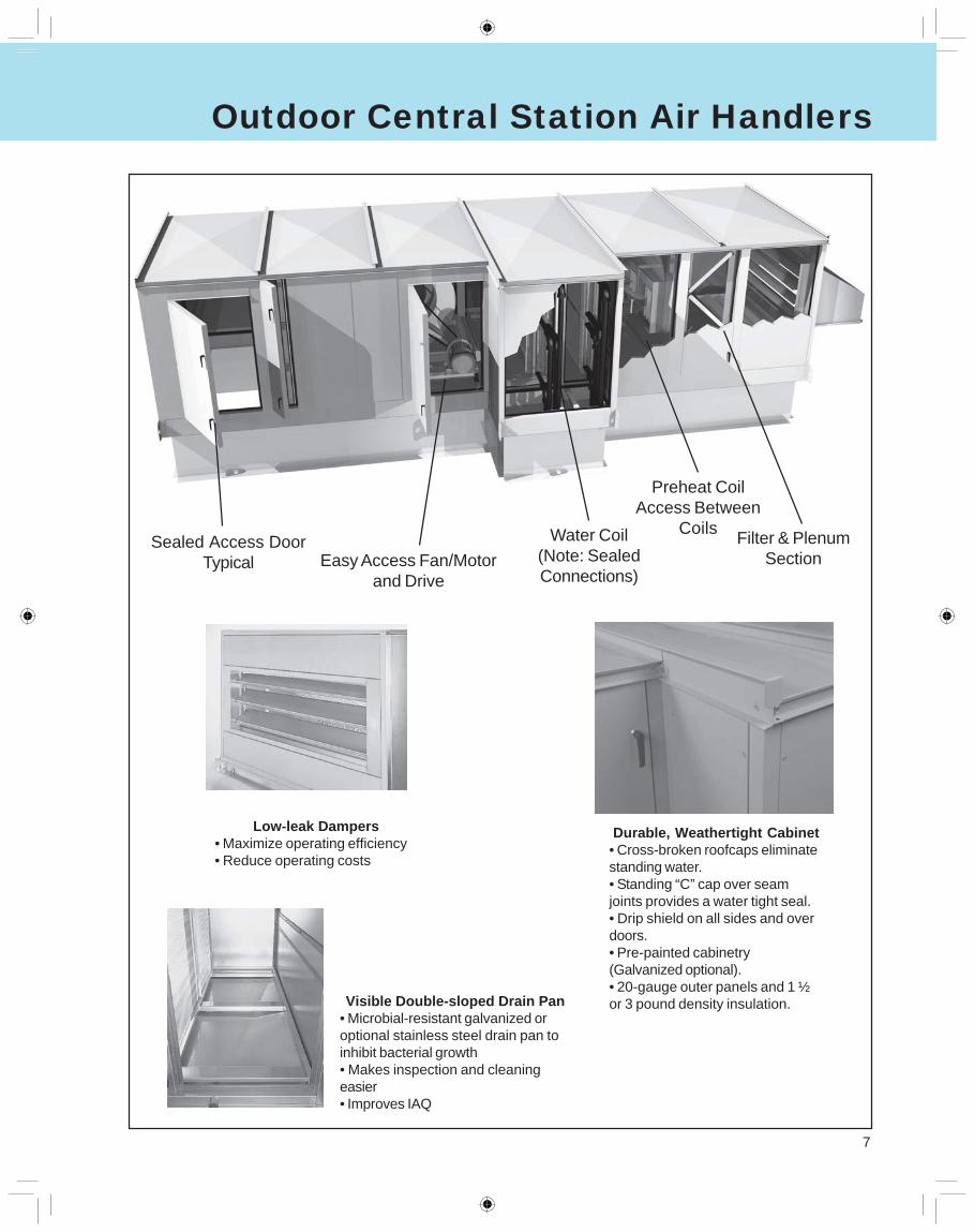
Durable, Weathertight Cabinet• Cross-broken roofcaps eliminatestanding water.• Standing “C” cap over seamjoints provides a water tight seal.• Drip shield on all sides and overdoors.• Pre-painted cabinetry(Galvanized optional).• 20-gauge outer panels and 1 ½or 3 pound density insulation.
Low-leak Dampers• Maximize operating efficiency• Reduce operating costs
Visible Double-sloped Drain Pan• Microbial-resistant galvanized oroptional stainless steel drain pan toinhibit bacterial growth• Makes inspection and cleaningeasier• Improves IAQ
Sealed Access DoorTypical
Water Coil(Note: SealedConnections)
Preheat CoilAccess Between
Coils Filter & PlenumSectionEasy Access Fan/Motor
and Drive
Outdoor Central Station Air Handlers
8
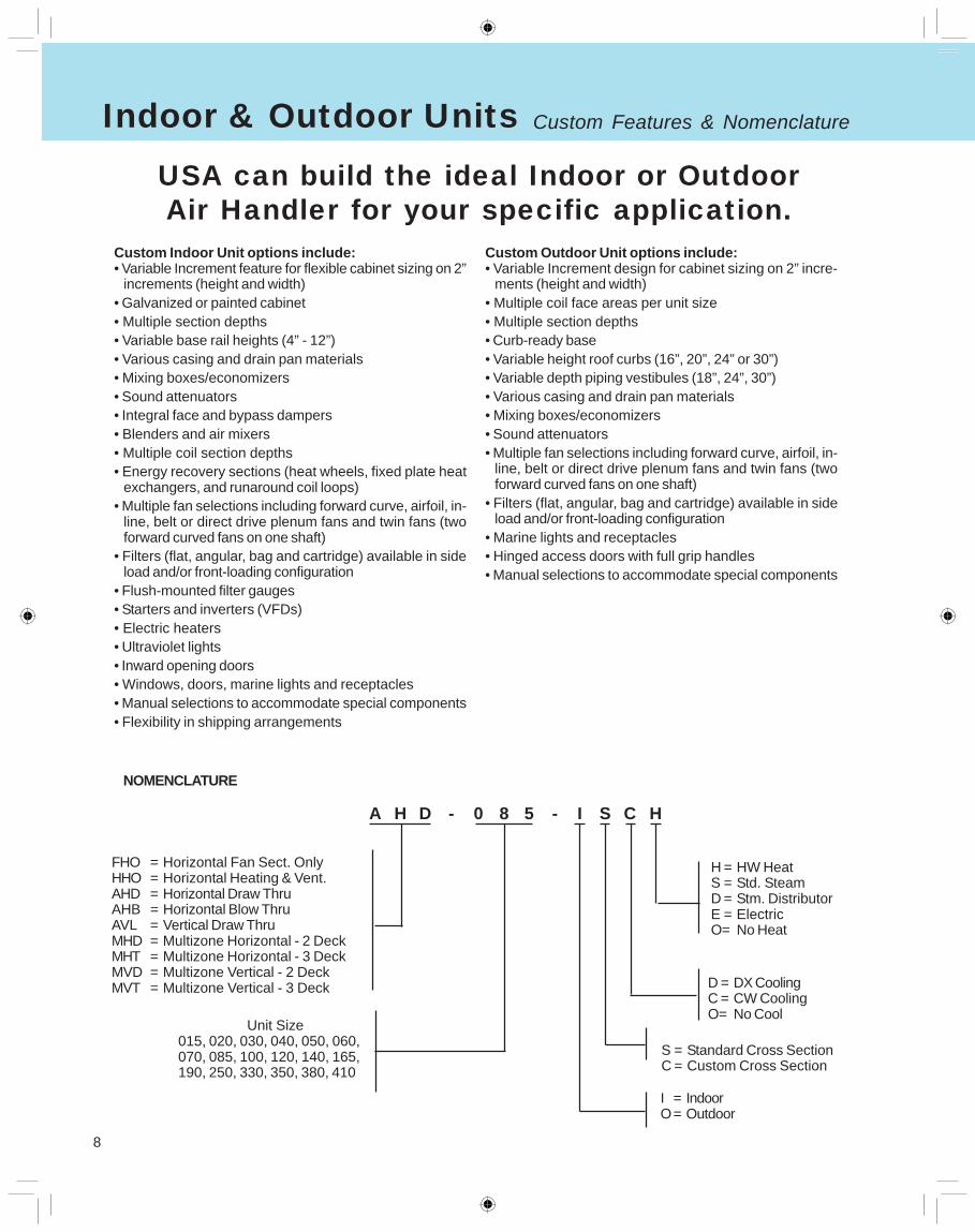
NOMENCLATURE
A H D - 0 8 5 - I S C H
FHO = Horizontal Fan Sect. OnlyHHO = Horizontal Heating & Vent.AHD = Horizontal Draw ThruAHB = Horizontal Blow ThruAVL = Vertical Draw ThruMHD = Multizone Horizontal - 2 DeckMHT = Multizone Horizontal - 3 DeckMVD = Multizone Vertical - 2 DeckMVT = Multizone Vertical - 3 Deck
Unit Size015, 020, 030, 040, 050, 060,070, 085, 100, 120, 140, 165,190, 250, 330, 350, 380, 410
I = IndoorO= Outdoor
S = Standard Cross SectionC = Custom Cross Section
H = HW HeatS = Std. SteamD = Stm. DistributorE = ElectricO= No Heat
D = DX CoolingC = CW CoolingO= No Cool
Custom Indoor Unit options include:• Variable Increment feature for flexible cabinet sizing on 2”
increments (height and width)• Galvanized or painted cabinet• Multiple section depths• Variable base rail heights (4” - 12”)• Various casing and drain pan materials• Mixing boxes/economizers• Sound attenuators• Integral face and bypass dampers• Blenders and air mixers• Multiple coil section depths• Energy recovery sections (heat wheels, fixed plate heat
exchangers, and runaround coil loops)• Multiple fan selections including forward curve, airfoil, in-
line, belt or direct drive plenum fans and twin fans (twoforward curved fans on one shaft)
• Filters (flat, angular, bag and cartridge) available in sideload and/or front-loading configuration
• Flush-mounted filter gauges• Starters and inverters (VFDs)• Electric heaters• Ultraviolet lights• Inward opening doors• Windows, doors, marine lights and receptacles• Manual selections to accommodate special components• Flexibility in shipping arrangements
USA can build the ideal Indoor or OutdoorAir Handler for your specific application.
Custom Outdoor Unit options include:• Variable Increment design for cabinet sizing on 2” incre-
ments (height and width)• Multiple coil face areas per unit size• Multiple section depths• Curb-ready base• Variable height roof curbs (16”, 20”, 24” or 30”)• Variable depth piping vestibules (18”, 24”, 30”)• Various casing and drain pan materials• Mixing boxes/economizers• Sound attenuators• Multiple fan selections including forward curve, airfoil, in-
line, belt or direct drive plenum fans and twin fans (twoforward curved fans on one shaft)
• Filters (flat, angular, bag and cartridge) available in sideload and/or front-loading configuration
• Marine lights and receptacles• Hinged access doors with full grip handles• Manual selections to accommodate special components
Indoor & Outdoor Units Custom Features & Nomenclature
9
Standard Components
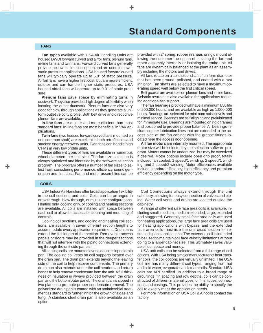
Fan types available with USA Air Handling Units arehoused DWDI forward curved and airfoil fans, plenum fans,in-line fans and twin fans. Forward curved fans generallyprovide the lowest first cost option and are used for lowerstatic pressure applications. USA housed forward curvedfans will typically operate up to 6.0” of static pressure.Airfoil fans have a higher first cost, but are more efficient,quieter and can handle higher static pressures. USAhoused airfoil fans will operate up to 9.0” of static pres-sure.
Plenum fans save space by eliminating turns inductwork. They also provide a high degree of flexibility whenlocating the outlet ductwork. Plenum fans are also verygood for blow through applications as they generate a uni-form outlet velocity profile. Both belt drive and direct driveplenum fans are available.
In-line fans are quieter and more efficient than moststandard fans. In-line fans are most beneficial in VAV ap-plications.
Twin fans (two housed forward curved fans mounted onone common shaft) are excellent in both retrofit units andstacked energy recovery units. Twin fans can handle highCFMs in very low profile units.
These different types of fans are available in numerouswheel diameters per unit size. The fan size selection isalways optimized and identified by the software selectionprogram. The program offers a number of fan sizes to se-lect from, considering performance, efficiency, sound gen-eration and first cost. Fan and motor assemblies can be
provided with 2” spring, rubber in shear, or rigid mount al-lowing the customer the option of isolating the fan andmotor assembly internally or isolating the entire unit. Allfans are dynamically balanced at the plant as an assem-bly including the motors and drives.
All fans rotate on a solid steel shaft of uniform diameterthat has been ground, polished, and coated with a rustinhibitor. Fan shafts are selected to have a maximum op-erating speed well below the first critical speed.
Belt guards are available on plenum fans and in-line fans.Seismic restraint is also available for applications requir-ing additional fan support.
The fan bearings provided will have a minimum L50 lifeof 200,000 hours, and are available as high as 1,000,000hours. Bearings are selected for minimum noise levels andminimal service. Bearings are self aligning and prelubricatedfor immediate use. Bearings are mounted on rigid framesand positioned to provide proper balance. All bearings in-clude copper lubrication lines that are extended to the ac-cess side of the fan cabinet with the grease fittings lo-cated near the access door opening.
All fan motors are internally mounted. The appropriatemotor size will be selected by the selection software pro-gram. Motors cannot be undersized, but may be oversizedif desired. Motor options include open drip proof, totallyinclosed fan cooled, 1 speed/1 winding, 2 speed/1 wind-ing, and 2 speed/2 winding. Motor efficiencies availableinclude standard efficiency, high efficiency and premiumefficiency depending on the motor type.
USA Indoor Air Handlers offer broad application flexibilityin the coil sections and coils. Coils can be arranged indraw through, blow through, or multizone configurations.Heating only, cooling only, or cooling and heating sectionsare available. All coils are installed with space betweeneach coil to allow for access for cleaning and mounting ofcontrols.
Cooling coil sections, and cooling and heating coil sec-tions, are available in seven different section lengths toaccommodate every application requirement. Drain pansextend the full length of the section. Removable accesspanels or doors may be provided in the deeper sectionsthat will not interfere with the piping connections extend-ing through the unit side panels.
All cooling coils are mounted over a double sloped drainpan. The cooling coil rests on coil supports located overthe drain pan. The drain pan extends beyond the leavingside of the coil to help recover condensate. The primarydrain pan also extends under the coil headers and returnbends to help remove condensate from the unit. A full thick-ness of insulation is always provided between the drainpan and the bottom outer panel. The drain pan is sloped intwo planes to promote proper condensate removal. Thegalvanized drain pan is coated with an antimicrobial treat-ment as standard to further inhibit the growth of algae andfungi. A stainless steel drain pan is also available as anoption.
Coil Connections always extend through the unitcabinetry, allowing for easy connection of valves and pip-ing. Water coil vents and drains are located outside thecabinetry.
A range of different size face area coils is available, in-cluding small, medium, medium extended, large, extendedand staggered. Generally small face area coils are usedfor heating applications, the large face area coils are usedfor heating applications with bypass, and the extendedface area coils maximize the unit cross section for re-stricted space applications. The extended coil is intendedto be used to maintain coil face velocity limitations withoutgoing to a larger cabinet size. This ultimately saves valu-able floor space and money.
USA unit coils can be selected from a full range of coiloptions. With USA being a major manufacturer of heat trans-fer coils, the coil options are virtually unlimited. The USAcoil line has many different coil types, ranging from hotand cold water, evaporator and steam coils. Standard USAcoils are ARI certified. In addition to a broad range ofcircuitings, fin spacing and row depths, coils can be con-structed of different material types for fins, tubes, connec-tions and casings. This provides the ability to specify thecoil to exactly meet the application needs.
For more information on USA Coil & Air coils contact thefactory.
FANS
COILS
10
Standard Components
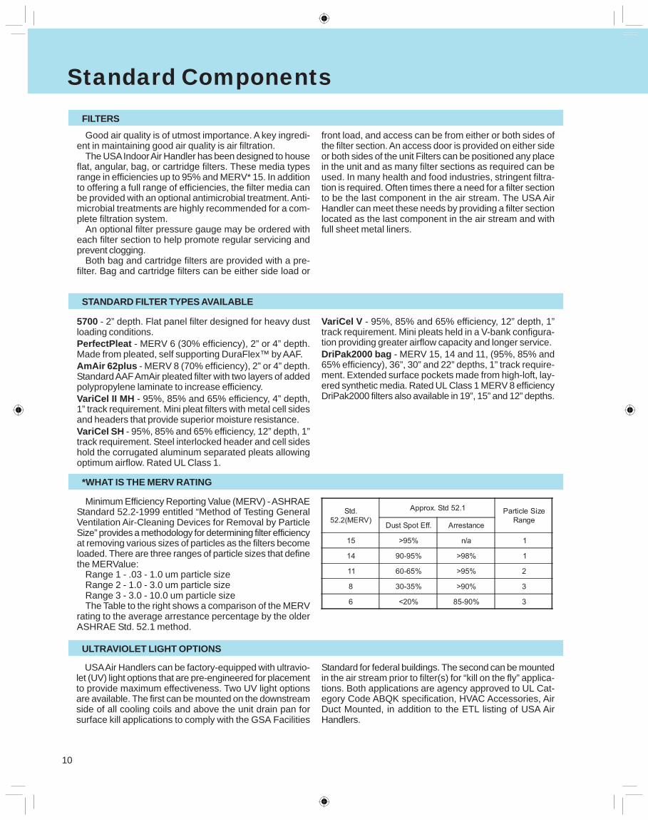
Good air quality is of utmost importance. A key ingredi-ent in maintaining good air quality is air filtration.
The USA Indoor Air Handler has been designed to houseflat, angular, bag, or cartridge filters. These media typesrange in efficiencies up to 95% and MERV* 15. In additionto offering a full range of efficiencies, the filter media canbe provided with an optional antimicrobial treatment. Anti-microbial treatments are highly recommended for a com-plete filtration system.
An optional filter pressure gauge may be ordered witheach filter section to help promote regular servicing andprevent clogging.
Both bag and cartridge filters are provided with a pre-filter. Bag and cartridge filters can be either side load or
front load, and access can be from either or both sides ofthe filter section. An access door is provided on either sideor both sides of the unit Filters can be positioned any placein the unit and as many filter sections as required can beused. In many health and food industries, stringent filtra-tion is required. Often times there a need for a filter sectionto be the last component in the air stream. The USA AirHandler can meet these needs by providing a filter sectionlocated as the last component in the air stream and withfull sheet metal liners.
5700 - 2” depth. Flat panel filter designed for heavy dustloading conditions.PerfectPleat - MERV 6 (30% efficiency), 2” or 4” depth.Made from pleated, self supporting DuraFlex™ by AAF.AmAir 62plus - MERV 8 (70% efficiency), 2” or 4” depth.Standard AAF AmAir pleated filter with two layers of addedpolypropylene laminate to increase efficiency.VariCel II MH - 95%, 85% and 65% efficiency, 4” depth,1” track requirement. Mini pleat filters with metal cell sidesand headers that provide superior moisture resistance.VariCel SH - 95%, 85% and 65% efficiency, 12” depth, 1”track requirement. Steel interlocked header and cell sideshold the corrugated aluminum separated pleats allowingoptimum airflow. Rated UL Class 1.
VariCel V - 95%, 85% and 65% efficiency, 12” depth, 1”track requirement. Mini pleats held in a V-bank configura-tion providing greater airflow capacity and longer service.DriPak2000 bag - MERV 15, 14 and 11, (95%, 85% and65% efficiency), 36”, 30” and 22” depths, 1” track require-ment. Extended surface pockets made from high-loft, lay-ered synthetic media. Rated UL Class 1 MERV 8 efficiencyDriPak2000 filters also available in 19”, 15” and 12” depths.
Minimum Efficiency Reporting Value (MERV) - ASHRAEStandard 52.2-1999 entitled “Method of Testing GeneralVentilation Air-Cleaning Devices for Removal by ParticleSize” provides a methodology for determining filter efficiencyat removing various sizes of particles as the filters becomeloaded. There are three ranges of particle sizes that definethe MERValue:
Range 1 - .03 - 1.0 um particle sizeRange 2 - 1.0 - 3.0 um particle sizeRange 3 - 3.0 - 10.0 um particle sizeThe Table to the right shows a comparison of the MERV
rating to the average arrestance percentage by the olderASHRAE Std. 52.1 method.
USA Air Handlers can be factory-equipped with ultravio-let (UV) light options that are pre-engineered for placementto provide maximum effectiveness. Two UV light optionsare available. The first can be mounted on the downstreamside of all cooling coils and above the unit drain pan forsurface kill applications to comply with the GSA Facilities
Standard for federal buildings. The second can be mountedin the air stream prior to filter(s) for “kill on the fly” applica-tions. Both applications are agency approved to UL Cat-egory Code ABQK specification, HVAC Accessories, AirDuct Mounted, in addition to the ETL listing of USA AirHandlers.
FILTERS
STANDARD FILTER TYPES AVAILABLE
*WHAT IS THE MERV RATING
ULTRAVIOLET LIGHT OPTIONS
11
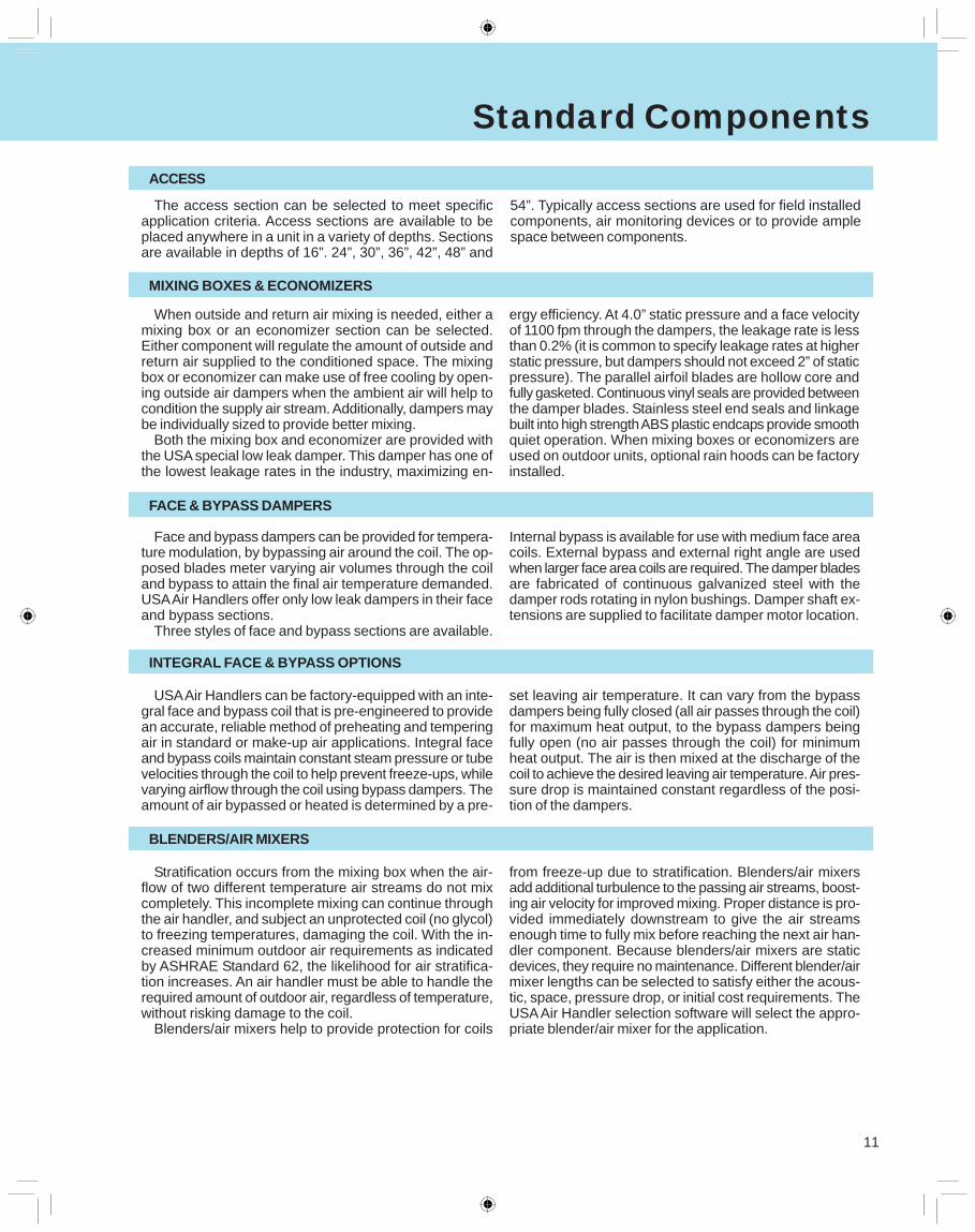
The access section can be selected to meet specificapplication criteria. Access sections are available to beplaced anywhere in a unit in a variety of depths. Sectionsare available in depths of 16”. 24”, 30”, 36”, 42”, 48” and
When outside and return air mixing is needed, either amixing box or an economizer section can be selected.Either component will regulate the amount of outside andreturn air supplied to the conditioned space. The mixingbox or economizer can make use of free cooling by open-ing outside air dampers when the ambient air will help tocondition the supply air stream. Additionally, dampers maybe individually sized to provide better mixing.
Both the mixing box and economizer are provided withthe USA special low leak damper. This damper has one ofthe lowest leakage rates in the industry, maximizing en-
54”. Typically access sections are used for field installedcomponents, air monitoring devices or to provide amplespace between components.
ergy efficiency. At 4.0” static pressure and a face velocityof 1100 fpm through the dampers, the leakage rate is lessthan 0.2% (it is common to specify leakage rates at higherstatic pressure, but dampers should not exceed 2” of staticpressure). The parallel airfoil blades are hollow core andfully gasketed. Continuous vinyl seals are provided betweenthe damper blades. Stainless steel end seals and linkagebuilt into high strength ABS plastic endcaps provide smoothquiet operation. When mixing boxes or economizers areused on outdoor units, optional rain hoods can be factoryinstalled.
Face and bypass dampers can be provided for tempera-ture modulation, by bypassing air around the coil. The op-posed blades meter varying air volumes through the coiland bypass to attain the final air temperature demanded.USA Air Handlers offer only low leak dampers in their faceand bypass sections.
Three styles of face and bypass sections are available.
Internal bypass is available for use with medium face areacoils. External bypass and external right angle are usedwhen larger face area coils are required. The damper bladesare fabricated of continuous galvanized steel with thedamper rods rotating in nylon bushings. Damper shaft ex-tensions are supplied to facilitate damper motor location.
USA Air Handlers can be factory-equipped with an inte-gral face and bypass coil that is pre-engineered to providean accurate, reliable method of preheating and temperingair in standard or make-up air applications. Integral faceand bypass coils maintain constant steam pressure or tubevelocities through the coil to help prevent freeze-ups, whilevarying airflow through the coil using bypass dampers. Theamount of air bypassed or heated is determined by a pre-
set leaving air temperature. It can vary from the bypassdampers being fully closed (all air passes through the coil)for maximum heat output, to the bypass dampers beingfully open (no air passes through the coil) for minimumheat output. The air is then mixed at the discharge of thecoil to achieve the desired leaving air temperature. Air pres-sure drop is maintained constant regardless of the posi-tion of the dampers.
Stratification occurs from the mixing box when the air-flow of two different temperature air streams do not mixcompletely. This incomplete mixing can continue throughthe air handler, and subject an unprotected coil (no glycol)to freezing temperatures, damaging the coil. With the in-creased minimum outdoor air requirements as indicatedby ASHRAE Standard 62, the likelihood for air stratifica-tion increases. An air handler must be able to handle therequired amount of outdoor air, regardless of temperature,without risking damage to the coil.
Blenders/air mixers help to provide protection for coils
from freeze-up due to stratification. Blenders/air mixersadd additional turbulence to the passing air streams, boost-ing air velocity for improved mixing. Proper distance is pro-vided immediately downstream to give the air streamsenough time to fully mix before reaching the next air han-dler component. Because blenders/air mixers are staticdevices, they require no maintenance. Different blender/airmixer lengths can be selected to satisfy either the acous-tic, space, pressure drop, or initial cost requirements. TheUSA Air Handler selection software will select the appro-priate blender/air mixer for the application.
Standard ComponentsACCESS
MIXING BOXES & ECONOMIZERS
FACE & BYPASS DAMPERS
INTEGRAL FACE & BYPASS OPTIONS
BLENDERS/AIR MIXERS
12
Standard Components
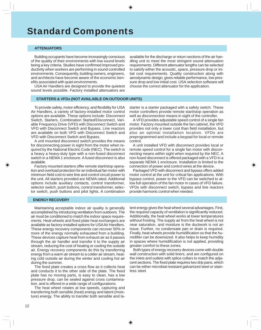
Building occupants have become increasingly consciousof the quality of their environments with low sound levelsbeing a key criteria. Studies have confirmed improved pro-ductivity when workers are performing in sound controlledenvironments. Consequently, building owners, engineers,and architects have become aware of the economic ben-efits associated with quiet environments.
USA Air Handlers are designed to provide the quietestsound levels possible. Factory installed attenuators are
available for the discharge or return sections of the air han-dling unit to meet the most stringent sound attenuationrequirements. Different attenuator lengths can be selectedto satisfy either the acoustic, space, pressure drop or ini-tial cost requirements. Quality construction along withaerodynamic design, gives reliable performance, low pres-sure drop and low initial cost. USA selection software willchoose the correct attenuator for the application.
To provide safety, motor efficiency, and flexibility for USAAir Handlers, a variety of factory-installed motor controloptions are available. These options include: DisconnectSwitch, Starters, Combination Started/Disconnect, Vari-able Frequency Drive (VFD) with Disconnect Switch andVFD with Disconnect Switch and Bypass. Line reactorsare available on both VFD with Disconnect Switch andVFD with Disconnect Switch and Bypass.
A unit mounted disconnect switch provides the meansfor disconnecting power in sight from the motor when re-quired by the National Electric Code (NEC). The switch isa heavy a heavy-duty type with a non-fused disconnectswitch in a NEMA 1 enclosure. A fused disconnect is alsoavailable.
Factory mounted starters offer remote start/stop opera-tion and overload protection for an individual fan motor withminimum field cost to wire line and control circuit power tothe unit. All starters provided are NEMA rated. Additionaloptions include auxiliary contacts, control transformer,selector switch, push buttons, control transformer, selec-tor switch, push buttons and pilot lights. A combination
starter is a starter packaged with a safety switch. Thesemotor controllers provide remote start/stop operation aswell as disconnection means in sight of the controller.
A VFD provides adjustable speed control of a single fanmotor. Factory mounted outside the fan cabinet, the VFDprovides not only a lower cost than field installation, butalso an optimal installation location. VFDs arepreprogrammed and include a keypad for local or remotecontrol.
A unit installed VFD with disconnect provides local orremote speed control for a single fan motor with discon-necting means within sight when required by the NEC. Anon-fused disconnect is offered packaged with a VFD in aseparate NEMA 1 enclosure. Installation is limited to theconnection of power and control wires at the device.
Packaged VFD with disconnect and bypass offers addedmotor control at the unit for critical fan applications. Withbypass control, power to the VFD can be switched to al-low full operation of the fan motor in cases of VFD failure.VFDs with disconnect switch, bypass and line reactorsprovide harmonic control when needed.
Maintaining acceptable indoor air quality is generallyaccomplished by introducing ventilation from outdoors. Theair must be conditioned to match the indoor space require-ments. Heat wheels and fixed plate heat exchangers areavailable as factory-installed options for USA Air Handlers.These energy recovery components can recover 50% ormore of the energy normally exhausted from a building.These devices capture heat from exhaust air as it passesthrough the air handler and transfer it to the supply airstream, reducing the cost of heating or cooling the outsideair. Energy recovery components do this by transferringenergy from a warm air stream to a colder air stream, heat-ing cold outside air during the winter and cooling hot airduring the summer.
The fixed plate creates a cross flow as it collects heatand conducts it to the other side of the plate. The fixedplate has no moving parts, is easy to clean, has a lowpressure drop, can be sealed against cross contamina-tion, and is offered in a wide range of configurations.
The heat wheel rotates at low speeds, capturing andtransferring both sensible (heat) energy and latent (mois-ture) energy. The ability to transfer both sensible and la-
tent energy gives the heat wheel several advantages. First,the required capacity of ventilation is significantly reduced.Additionally, the heat wheel works at lower temperatureswithout frosting. The supply air from the heat wheel is notnear saturation, and moisture is the ductwork is not anissue. Further, no condensate pan or drain is required.Finally, heat wheels provide humidification so that the hu-midifier can be downsized. It also helps to keep humidityin spaces where humidification is not applied, providinggreater comfort to these zones.
Both types of energy recovery devices come with doublewall construction with solid liners, and are configured onthe inlets and outlets with splice collars to match the adja-cent sections. The fixed plate requires two drip pans, whichcan be either microbial resistant galvanized steel or stain-less steel.
ATTENUATORS
STARTERS & VFDs (NOT AVAILABLE ON OUTDOOR UNITS)
ENERGY RECOVERY
13
Standard Components
Electric Heaters extend the wide versatility of USA AirHandlers. With negligible air pressure drop, accurate con-trollability, light weight, easy serviceability and inherentfreeze protection, electric heaters are valuable alternativesto conventional steam and hot water heating coils.
ETL-approved electric heaters are available on all stan-dard sizes (003-090) for horizontally-mounted draw throughunits in both left and right hand configurations. All units areopen wire style construction, with automatic and manualbackup limit controls, air switch, stainless steel terminals,power on pilot light, magnetic contactors and integral con-trol boxes. Safety interlock switches, step controllers andvernier silicon controlled rectifiers (SCRs) are availableoptions.
The heater requires its own electric service. Heaters areavailable in 208V, 240V, 480V and 600V (all 3 phase) and
use an internal 24-volt control circuit. Standard ranges ofkW are available for each heater size and are designed togive an approximate temperature rise from 20ºF to 60ºF,depending on the airflow through the unit. Typical pressuredrops range from .01-.04 inches of water, depending onthe air velocity and number of rows of heating elements.
An integral control box with optional door handle powerdisconnect is included with the electric heater. Insulatedpanels are factory installed behind the control box. Anystandard motor may be used, although the discharge airfrom the electric heater must not exceed 104ºF since therated ambient temperature of the motor will be exceeded.The heater is assembled into a separate section of theUSA Air Handler. Standard section widths include: 30”,34”, 42” and 46” and vary depending on the unit size, con-trol type and kW used.
ELECTRIC HEATERS (NOT AVAILABLE ON OUTDOOR UNITS)
14
Quick Select Table
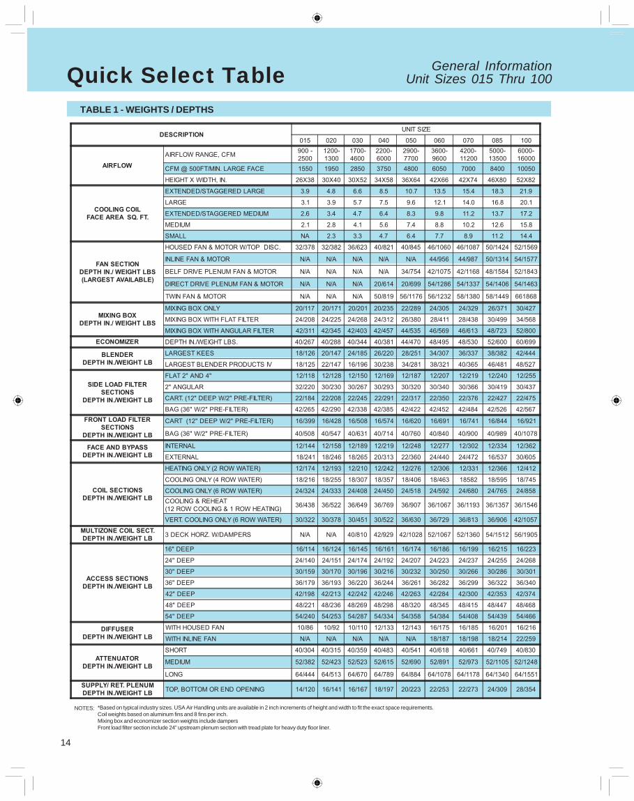
*Based on typical industry sizes. USA Air Handling units are available in 2 inch increments of height and width to fit the exact space requirements.Coil weights based on aluminum fins and 8 fins per inch.Mixing box and economizer section weights include dampersFront load filter section include 24” upstream plenum section with tread plate for heavy duty floor liner.
NOTES:
General InformationUnit Sizes 015 Thru 100
TABLE 1 - WEIGHTS / DEPTHS
15
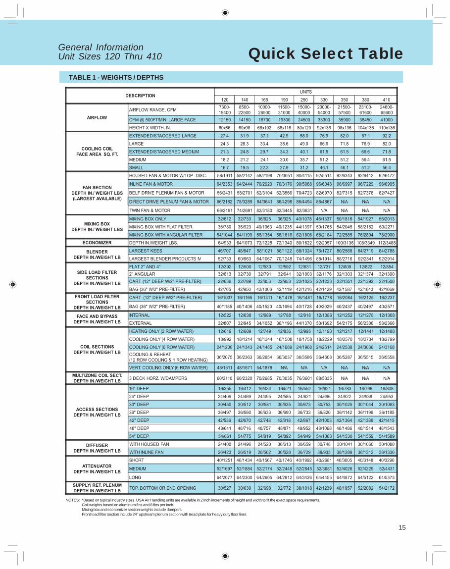
General InformationUnit Sizes 120 Thru 410 Quick Select Table
*Based on typical industry sizes. USA Air Handling units are available in 2 inch increments of height and width to fit the exact space requirements.Coil weights based on aluminum fins and 8 fins per inch.Mixing box and economizer section weights include dampersFront load filter section include 24” upstream plenum section with tread plate for heavy duty floor liner.
NOTES:
TABLE 1 - WEIGHTS / DEPTHS
16
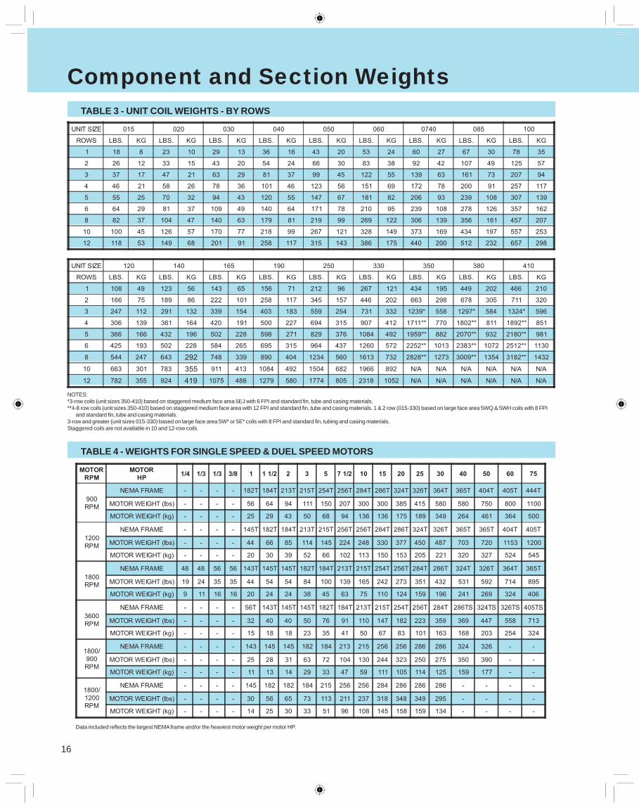
Component and Section WeightsTABLE 3 - UNIT COIL WEIGHTS - BY ROWS
TABLE 4 - WEIGHTS FOR SINGLE SPEED & DUEL SPEED MOTORS
Data included reflects the largest NEMA frame and/or the heaviest motor weight per motor HP.
NOTES:*3-row coils (unit sizes 350-410) based on staggered medium face area 5EJ with 6 FPI and standard fin, tube and casing materials.**4-8 row coils (unit sizes 350-410) based on staggered medium face area with 12 FPI and standard fin, tube and casing materials. 1 & 2 row (015-330) based on large face area 5WQ & 5WH coils with 8 FPI
and standard fin, tube and casing materials.3-row and greater (unit sizes 015-330) based on large face area 5W* or 5E* coils with 8 FPI and standard fin, tubing and casing materials.Staggered coils are not available in 10 and 12-row coils.
17
Component and Section Weights
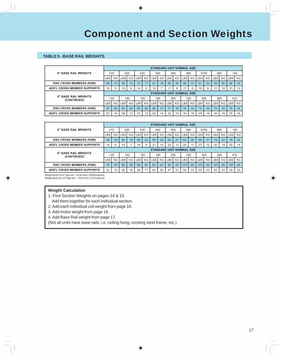
TABLE 5 - BASE RAIL WEIGHTS
Weight factor for 6” high rail = .52 lb./inch (.00929 kg/mm).Weight factor for 10” high rail = .74 lb./inch (.0132 kg/mm).
Weight Calculation1. Find Section Weights on pages 14 & 15.
Add them together for each individual section.2. Add each individual coil weight from page 16.3. Add motor weight from page 16.4. Add Base Rail weight from page 17.(Not all units have base rails; i.e. ceiling hung, existing steel frame, etc.)
18
Engineering ConsiderationsINSTALLATION FLEXIBILITY
USA Coil & Air central station air handlers featuresectionalized design to provide maximum installation flex-ibility. Fan, coil, filter, mixing box, face and bypass and ac-cess components allow the design flexibility of built-up sys-
tems with the cost advantage of factory fabricated units. Unitscan be shipped from the factory in as few or as many sec-tions as required according to job site condition.
MOUNTING & ACCESS
Whether units are floor or ceiling mounted, care should betaken to keep the supporting structure level and rigid enoughfor satisfactory unit operation. Ideally, a heavy concrete slabshould be used for floor mounted units, and main supportbeams for ceiling hung units. Ceiling suspended units mustbe trapeezed from the unit base rail, or field supplied materi-als. Long floor or ceiling spans should be avoided.
Units should be located so as to provide proper access forroutine service. Clearance for filter removal on both sides of
the filter section is usually necessary. Clearance should beprovided as required for access panels. Room should be al-lowed for coil removal. Cooling units require clearance for atrap in the drain line.
Access to the interior of the USA Air Handler is providedby hinged access doors or removable panels. For accessbetween components, versatile access sections featurehinged access doors on either, or both sides.
DUCTWORK
Good ductwork layout will minimize system resistance andsound generation. Duct connections to and from units shouldallow straight, smooth airflow. Sharp turns in the fan dis-charge should be avoided, particularly turns opposed to wheel
rotation. Turning vanes should be used. Discharge plenumsor any abrupt change in duct size should be avoided.
PIPING & DRAIN PAN TRAPS
Piping should be used in accordance with accepted indus-try standards. Undue stress should not be applied at theconnection to coil headers. Pipe work should be supportedindependently of the coils with adequate piping flexibility forthermal expansion. Drain lines and traps should be run fullsize from the drain pan connection. Drain pans should have
traps to permit the condensate from the coils to drain freely.On a draw-through unit, the trap depth and the distance be-tween the trap outlet and drain pan outlet should be twicethe negative static pressure under normal unit operation.
VIBRATION ISOLATION
To help keep noise and vibration compatible with the in-tended use of the conditioned air space, good acousticaland vibration engineering practices should be applied duringthe early stages of design.
Since most applications require vibration isolation, the USAAir Handler is available with factory installed internal isola-tion. Internally isolated units feature spring or rubber in shearisolators sized specifically for each fan wheel and unit size.
MULTIZONE AIR HANDLER APPLICATIONS
Blow-through air handlers are available in single-zone, two-deck and three-deck configurations. The two- and three-deckunits are offered with or without zone dampers. All unit con-figurations include a perforated plate fan discharge diffuserto provide even airflow downstream of the fan.
Multi-zone and dual duct air handlers typically provide com-fort conditioning by distributing a constant air volume at vari-able temperature. In a typical system a portion of the air isheated by passing through the heating coil and the balanceis cooled by the cooling coil. The heated and cooled air-streams are then mixed in the required proportion to providethe optimum temperature air to the conditioned space.
For dual duct applications, a pair of ducts bring heatedand cooled air to the air mixing terminal boxes where theairstreams are mixed. By adding zone dampers to the dualduct unit, the air mixing takes place at the unit discharge
and only one duct is required to distribute conditioned air tothe building. The air mixing terminal boxes are also elimi-nated.
By adding a third bypass deck to the hot and cold decks,a triple deck multi-zone is created. The triple deck configura-tion offers significant energy conservation opportunities byallowing return or outside air to bypass both coils. The ther-mal inefficiency of mixing heated and cooled air is elimi-nated by the addition of the bypass deck. Bypass air is mixedwith heated air for building zones that require heating. By-pass air is mixed with cooled air for building zones that re-quire cooling.
Multi-zone systems result in the absence of water, steamand condensate drain piping, wiring, electrical and mechani-cal equipment in the conditioned space for more usable com-mercial floor area and higher rental income.
19
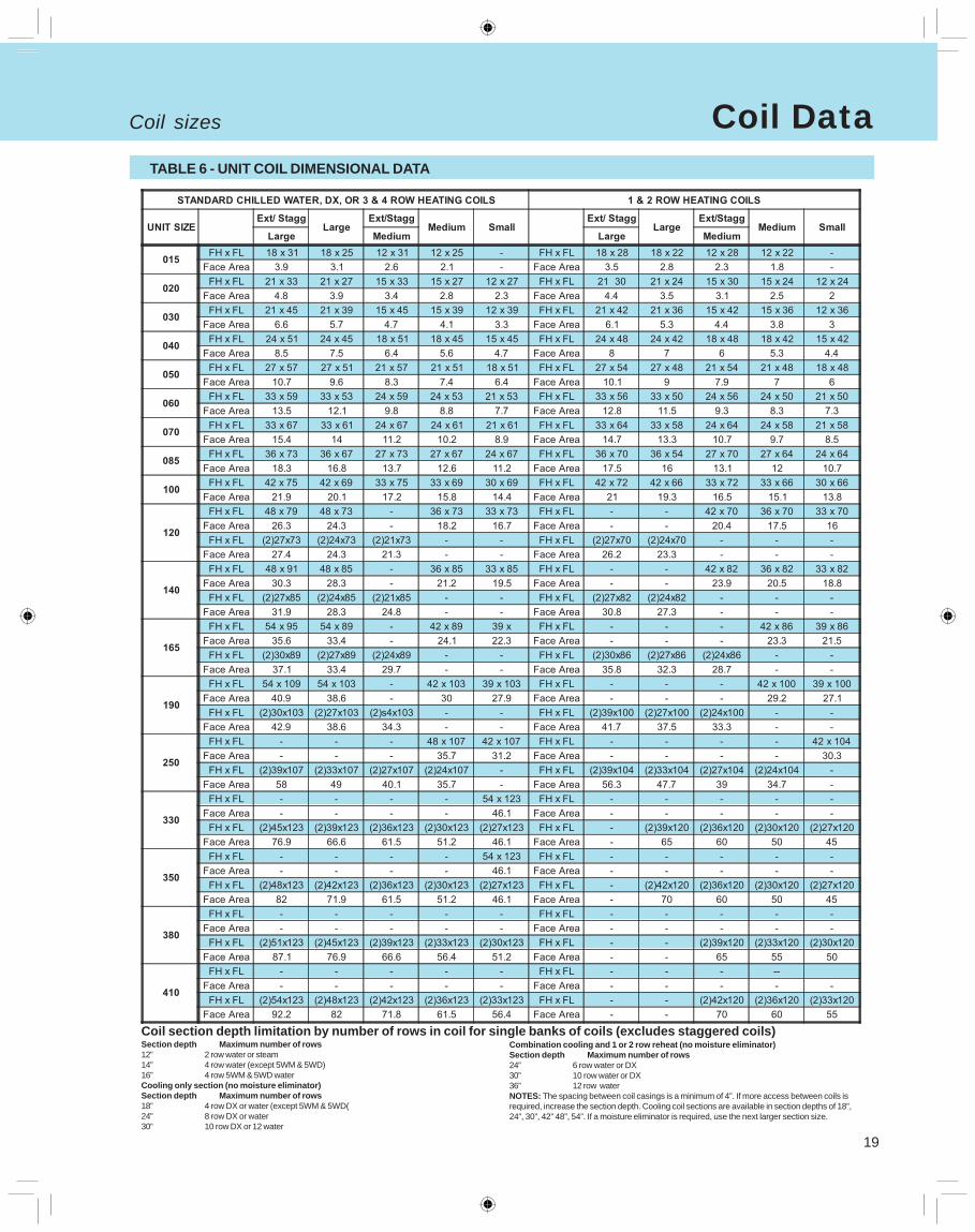
Coil DataTABLE 6 - UNIT COIL DIMENSIONAL DATA
Coil section depth limitation by number of rows in coil for single banks of coils (excludes staggered coils)Section depth Maximum number of rows12” 2 row water or steam14” 4 row water (except 5WM & 5WD)16” 4 row 5WM & 5WD waterCooling only section (no moisture eliminator)Section depth Maximum number of rows18” 4 row DX or water (except 5WM & 5WD(24” 8 row DX or water30” 10 row DX or 12 water
Combination cooling and 1 or 2 row reheat (no moisture eliminator)Section depth Maximum number of rows24” 6 row water or DX30” 10 row water or DX36” 12 row waterNOTES: The spacing between coil casings is a minimum of 4”. If more access between coils isrequired, increase the section depth. Cooling coil sections are available in section depths of 18”,24”, 30”, 42” 48”, 54”. If a moisture eliminator is required, use the next larger section size.
Coil sizes
20
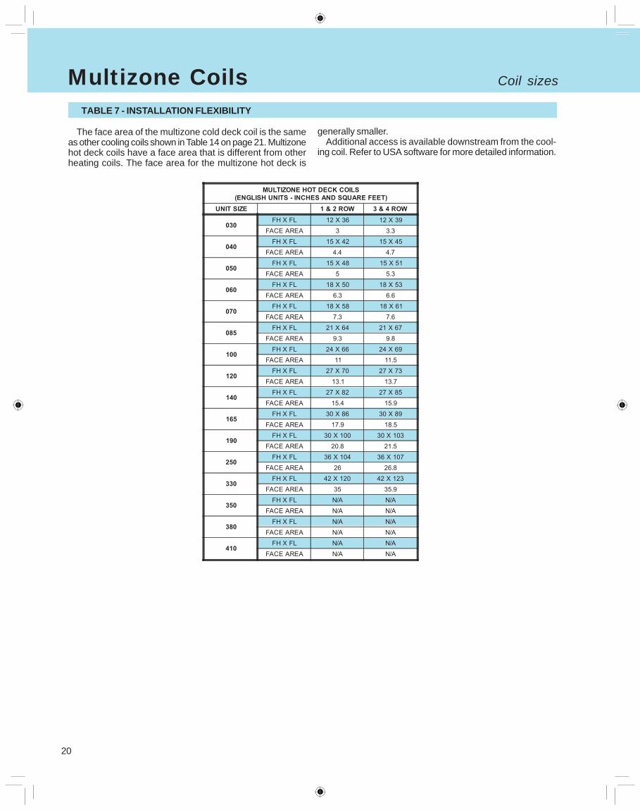
Multizone CoilsTABLE 7 - INSTALLATION FLEXIBILITY
The face area of the multizone cold deck coil is the sameas other cooling coils shown in Table 14 on page 21. Multizonehot deck coils have a face area that is different from otherheating coils. The face area for the multizone hot deck is
generally smaller.Additional access is available downstream from the cool-
ing coil. Refer to USA software for more detailed information.
Coil sizes
21
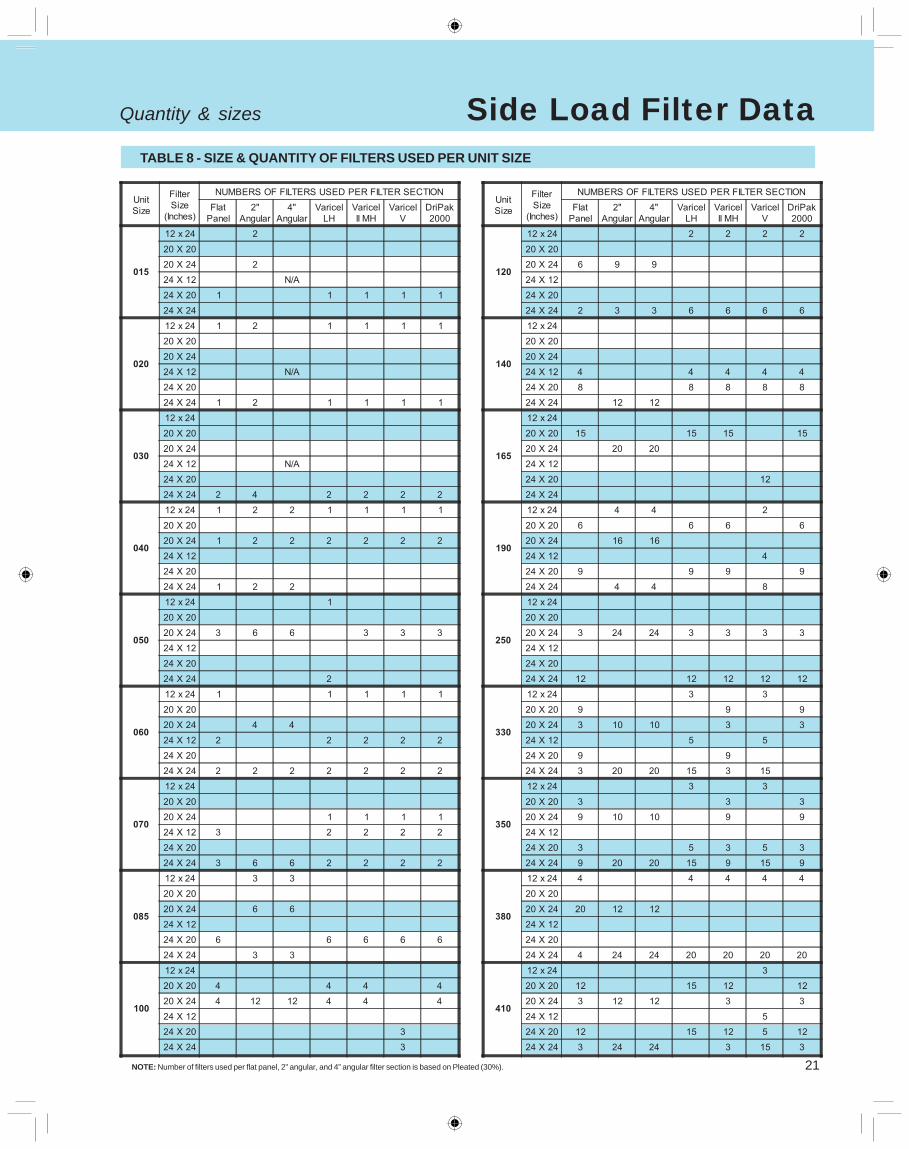
Side Load Filter DataTABLE 8 - SIZE & QUANTITY OF FILTERS USED PER UNIT SIZE
NOTE: Number of filters used per flat panel, 2” angular, and 4” angular filter section is based on Pleated (30%).
Quantity & sizes
22
Standard Specification Standard Specification(for estimate only)
Section reference: all applicable sections.
1. All casing channel posts shall be 16 gauge with remov-able panels constructed of either galvanized steel or paintedsteel. Sections shall have highly compressed gasketing be-tween frame members and doors. (Standard)
2. Outside casing shall be:2A - G90 Galvanized Steel -16 Ga.2B - G90 Galvanized Steel - 18 Ga.2C - G60 Steel and painted with enamel paint which meets600 hour salt spray test.
3. Internal lining for double wall units shall be 20 gauge:3A - G90 Galvanized Steel Solid3B - G90 Galvanized Steel Perforated3C - 304 Solid Stainless Steel
The units shall have inner liner for:3D - Fan Section only3E - Fan and Coil Section only3F - The entire unit in direction of air flow
4. Floor Plates shall be:4A - Standard G90 20 Ga. Galvanized Steel4B - G90 14 Ga. Galvanized Steel4C - 304 Stainless 20 Ga.4D - 304 Stainless Steel 14 Ga.4E - Aluminum - .125” thick
5. Entire unit shall have a full Perimeter Base Rail. TheRail height required shall be shown on plans and shall bebased on required trapping required for drain pans and/orsteam coil piping. (Standard)
6. A full perimeter overlapping with internal splice joint(sealed) with gasketing on mating sections meets indoorair quality standards. Unit leak rate shall not exceed 0.5CFM per square feet at 5” static pressure.
7. Insulation shall be high density, neoprene coated, glassfiber type with adhesive and pins on units that are singlewall type. Insulation shall be:7A - One inch7B - Two inch (Double wall only)
8. All access doors shall be flush mounted type, galvanizedsteel with a minimum of 2 six inch long stainless pianotype hinges, latches and full size handles (4.5” minimum).All doors shall swing outward for locations with negativepressure (usually upstream from fans) and inward for doorslocated with positive pressure. Positive pressure styleshave a secondary latch to relieve pressure. Positive pres-sure styles have a secondary latch to relieve pressure ondoors that can’t swing inward such as side access filtersections.8A - Standard door8B - Door and inspection window8C - Fan section only - Drive side8D - Fan section only - Both sides8E - Fan and coil sections - Drive side only8F - Fan and coil sections, both sides.
All doors located in coil sections may increase the overalllength of units and shall be between coils if multiple coilunit.
9. Drain pans shall be double sloped pitched type towardsthe drain connection. Drain connections to be located 3”above the base rails to allow for proper trapping.9A - Galvanized pan with microbial resistant coating9B - 304 Stainless Steel9C - Pan under cooling coils only9D - Pans in fan section and cooling coil sections
DESIGN, PERFORMANCE, ARRANGEMENT.
Provide USA Coil & Air Units including all accessoriesshown per plans, specifications and other related details.
GENERAL - CASING & FRAME
*Please note Option # next to available options.
23
SUPPLY AND RETURN AIR FANS
Standard Specification
Section reference: 01, 02, 03, 29, 30, 31, and 32.
10. All air moving assemblies including fans, motorsand drives shall be dynamically balanced at all three planesand at all bearing supports and will be available at an RPMbelow the first critical speed. Bearings shall be self aligned,grease lubricated with extended copper lube lines to ac-cess on side of unit as ordered. Provide supply fans:10A - DWDI centrifugal type - forward curved10B - DWDI centrifugal type - airfoil10C - Belt drive airfoil plenum style10D - In-line type10E - Forward curved - twin style fans10F - Supply fans only10G - Supply and return air fans
All fans and motors are internally mounted on steel baseand motor also on sliding adjustable base for proper belttension and alignment. Motor has easy slide out positionfor repairs or replacement. Fan and motor to be mountedon:10H - Rubber - in-shear isolators10J - 2” deflection spring isolators10K - 2” deflection spring isolators with seismic snubbers.
Section reference: 01, 02, 03, 29, 30, 31, 32.
11. Motors shall be mounted internally and shall be oftype, service and electrical characteristics as shown onschedule. Motors shall be:11A - Standard efficiency open type11B - High efficiency - open type11C - Premium efficiency open type11D - Totally enclosed - standard efficiency11E - 2-speed type open type standard efficiency
Wiring termination provide terminal lugs to match branch cir-cuit conductor quantities, sizes and materials indicated.(Box per NFPA 70.)
Provide:11F - Factory mounted starters and disconnects as shownon the schedule.
Bearings shall be self aligning, grease lubricated ball bear-ing type. Shafts are solid, hot rolled steel that are groundand polished and are keyed to shaft type and protectedwith industry approved oil. All v-belt drives shall be castiron, dynamically balanced, bored to fit shaft and keys.10L - Fixed sheave rated at motor HP10M - Variable - adjustable drives @ 1.25 service factor10N - Variable - adjustable drives @ 1.50 service factor
Adjustable sheaves and drives selected at stated RPM atmid point. Field personnel to supply replacement sheavesfor RPM requirements not specified when balancing re-quires new selection. All drives selected by USA shall betwo belt type at 10 HP and above.
Bearings to be per AFBMA-ANSI standards and shall berated at L-50 life based on type and size of unit but aminimum of 200,000 hours and a maximum of 500,000hours as standard (600,000 hours on in-line fans and400,000 on belt drive plenum fans). Bearing shall be self-aligning, grease lubricated ball bearing type. Shafts aresolid, hot rolled steel that are ground and polished and arekeyed to the shaft type and protected with industry ap-proved oil. All V-belt drives shall be cast iron, dynamicallybalanced, bored to fit shaft and keys.
Provide:11G - Factory mounted variable frequency drives.
Provide:11H - Marine light in fan section on the drive side of theunit.11J - Marine light with GFI receptacle in fan section on thedrive side of the unit.11K - Marine light in fan and all coil sections mounted ondrive side.11L - Marine light with GFI receptacle in fan and all coilsections mounted on drive side.
All lights are wired to a junction box and on-off switch onoutside of the cabinet.
MOTORS & WIRING
Standard Specification(for estimate only)
24
Standard SpecificationCOIL SECTIONS - HEATING & COOLING
Section Reference: 24, 25, 26, 27, 28, 32, 34, 40, 41,42 & 43
12. Unit mounted coils shall be provided with coil con-nections extending at least 5” beyond unit casing. Drainand vent connections shall be provided exterior to unit casingas well. All connections shall have factory sealing withgrommets on interior and exterior and gasket sleeve be-tween outer and inner walls, which minimizes air leakageand condensation inside the assembly. All coils shall be
removable through side and/or top panels of unit withoutthe need to remove or disassemble the coil section. Allreturn bends and coil headers shall be fully inside thecabinet and cooling coil access shall be from;12A - both sides of unit12B - Connections side only12C - Opposite connection side only for servicing or clean-ing. Access to coils is not access between coils but toprinciple parts on each end of coils.
HEAT TRANSFER COILS - HEATING, COOLING & SENTRY GUARD DESIGNS
Section reference: 24, 25, 26, 27, 28, 32, 34, 40, 41,42 & 43
13. All coils shall be either built with seamless coppertubes with plate style aluminum fins, copper headersand:13A - Steel MPT connections (water or steam coils)13B - Copper MPT connections (water or refrigerant sweatonly)13C - Red brass MPT connections (water or steam coilsonly).
Fins have full drawn collars and are continuous sur-face type. All tubes are mechanically expanded into thefins that creates a lifetime bond between primary and sec-ondary surfaces. No bare tubes shall be visible betweenthe fins. Seamless copper headers shall be provided andconstruction shall be such that tube sheet design doesnot cause stress with protruding tubes. Drain connectionsshall be located at the lowest point (water coils only). Allcoils tested at 315 pounds air pressure under warm waterand suited for 250 PSIG working pressure. Coils shall beARI certified and rated. All coils and connections sized perindustry standards based on flow/mass or other require-ments.
Refrigerant coils shall be designed for use with R-22 orR-134A and headers shall have sweat type connectionslocated at bottom of coils for proper oil return. Coils arefurnished with industry standard circuitry and distributorswith leads and orifices sized for proper tonnage and suc-tion temperatures.
Steam coils are tested at 315 pounds under warm wa-ter and are rated for 100 PSIG working pressure. All coilsshall be pitched towards condensate return and orifice bal-ance plates installed in supply header to properly diffusesteam to all tubes in coil.
All coils as designated on schedule shall have13D - 5/8” OD copper tubes with .0075” thick aluminumfins and galvanized steel casings13E - .025” wall copper tubes vs. standard wall13F - .035” wall copper tubes vs. standard wall13G - .010 thick aluminum fins vs. .0075” thick13H - .0075” thick copper fins in lieu of .0075” thick alumi-num fins13J - Stainless steel casing in lieu of galvanized steel cas-ings13K - Steam coils shall be 1” OD steam distributing typein lieu of 5/8” OD steam distributing type13L - All coils shall be coated with a six step epoxy coat-ing after fabrication of coil.13M - Coils shall be patented Sentry Guard burst resistantseries and constructed with special freeze plugs on allreturn bends, tubes and headers. Special fittings shall bescrew-on, screw-off design with easy to remove cap. Coilsshall be supplied with a 30 month Limited Freeze Resis-tant Warranty and a 12 month Limited Material and Work-manship Warranty.
Standard Specification(for estimate only)
25
Standard SpecificationAIR FILTERS
Section Reference: 06, 07, 08, 11, 12, 13, 14, 36 & 37
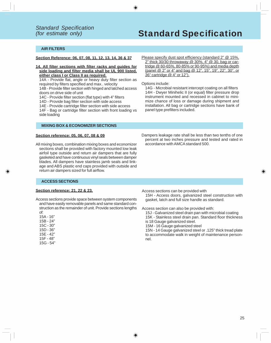
14. All filter sections with filter racks and guides forside loading and filter media shall be UL 900 listed,either class I or Class II as required.14A - Provide flat, angle or heavy duty filter section asrequired by filters specified and max.. velocity14B - Provide filter section with hinged and latched accessdoors on drive side of unit14C - Provide filter section (flat type) with 4” filters14D - Provide bag filter section with side access14E - Provide cartridge filter section with side access14F - Bag or cartridge filter section with front loading vsside loading
Please specify dust spot efficiency (standard 2” @ 15%,2” thick 30/30 throwaway @ 30%, 4” @ 30, bag or car-tridge @ 60-65%, 80-85% or 90-95%) and media depth(panel @ 2” or 4” and bag @ 12”, 15”, 19”, 22”, 30”, or36” cartridge @ 4” or 12”).
Options include:14G - Microbial resistant intercept coating on all filters14H - Dwyer Minihelic II (or equal) filter pressure dropinstrument mounted and recessed in cabinet to mini-mize chance of loss or damage during shipment andinstallation. All bag or cartridge sections have bank ofpanel type prefilters included.
MIXING BOX & ECONOMIZER SECTIONS
Section reference: 05, 06, 07, 08 & 09
All mixing boxes, combination mixing boxes and economizersections shall be provided with factory mounted low leakairfoil type outside and return air dampers that are fullygasketed and have continuous vinyl seals between damperblades. All dampers have stainless jamb seals and link-age and ABS plastic end caps provided with outside andreturn air dampers sized for full airflow.
Dampers leakage rate shall be less than two tenths of onepercent at two inches pressure and tested and rated inaccordance with AMCA standard 500.
ACCESS SECTIONS
Section reference: 21, 22 & 23.
Access sections provide space between system componentsand have easily removable panels and same standard con-struction as the remainder of unit. Provide sections lengthsof:15A - 16”15B - 24”15C - 30”15D - 36”15E - 42”15F - 48”15G - 54”
Access sections can be provided with15H - Access doors, galvanized steel construction withgasket, latch and full size handle as standard.
Access section can also be provided with:15J - Galvanized steel drain pan with microbial coating15K - Stainless steel drain pan. Standard floor thicknessis 18 Gauge galvanized steel.15M - 16 Gauge galvanized steel15N - 14 Gauge galvanized steel or .125” thick tread plateto accommodate walk in weight of maintenance person-nel.
Standard Specification(for estimate only)
26
Standard Specification
Section reference: All sections
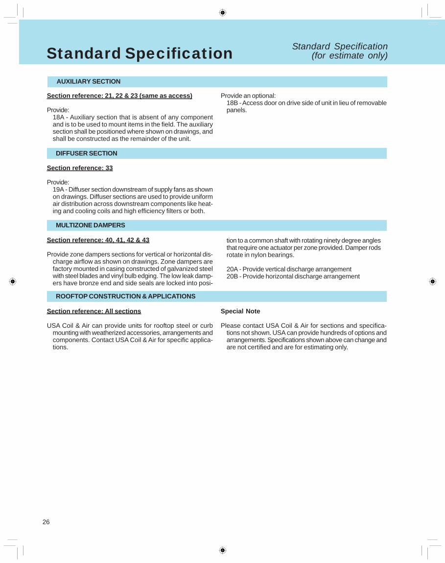
USA Coil & Air can provide units for rooftop steel or curbmounting with weatherized accessories, arrangements andcomponents. Contact USA Coil & Air for specific applica-tions.
AUXILIARY SECTION
Section reference: 21, 22 & 23 (same as access)
Provide:18A - Auxiliary section that is absent of any componentand is to be used to mount items in the field. The auxiliarysection shall be positioned where shown on drawings, andshall be constructed as the remainder of the unit.
Provide an optional:18B - Access door on drive side of unit in lieu of removablepanels.
DIFFUSER SECTION
Section reference: 33
Provide:19A - Diffuser section downstream of supply fans as shownon drawings. Diffuser sections are used to provide uniformair distribution across downstream components like heat-ing and cooling coils and high efficiency filters or both.
MULTIZONE DAMPERS
Section reference: 40, 41, 42 & 43
Provide zone dampers sections for vertical or horizontal dis-charge airflow as shown on drawings. Zone dampers arefactory mounted in casing constructed of galvanized steelwith steel blades and vinyl bulb edging. The low leak damp-ers have bronze end and side seals are locked into posi-
tion to a common shaft with rotating ninety degree anglesthat require one actuator per zone provided. Damper rodsrotate in nylon bearings.
20A - Provide vertical discharge arrangement20B - Provide horizontal discharge arrangement
ROOFTOP CONSTRUCTION & APPLICATIONS
Special Note
Please contact USA Coil & Air for sections and specifica-tions not shown. USA can provide hundreds of options andarrangements. Specifications shown above can change andare not certified and are for estimating only.
Standard Specification(for estimate only)
27
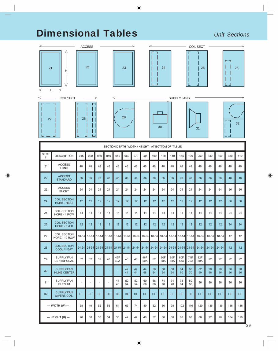
Unit SectionsDimensional Tables
123456123456
123123123123123123123
123456123456
123123123123123123123
12345671234567
123123123123123123123
12345671234567
123123123123123123123
1234567890112345678901
123123123123123123123
05 06 07 08 091234123412341234
10
MIXING BOX ECONO BLENDER
H01 01
02 03
04
RETURN FANS PLENUM
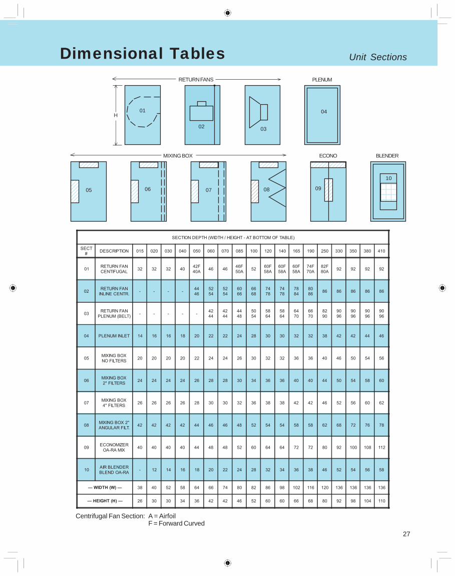
Centrifugal Fan Section: A = AirfoilF = Forward Curved
28
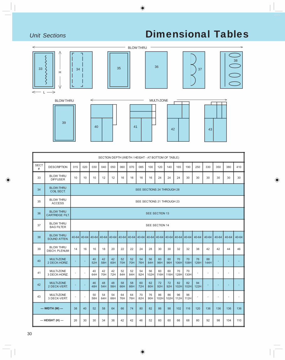
Unit Sections Dimensional Tables
15
16
17 18 1920
ENERGY REC. BYPASS
H 11 12 14
FILTERS
L
1313
15
29
Unit SectionsDimensional Tables
COIL SECT.
27 28
SUPPLY FANS
29 01
30 3132
24
COIL SECT.
25 2621
ACCESS
22 23
L
H21 22 23
27 28
30
Unit Sections Dimensional Tables
BLOW THRU
3940
MULTI-ZONE
4241
43
3637
38
33
BLOW THRU
34 35
L
H35
39
33
31
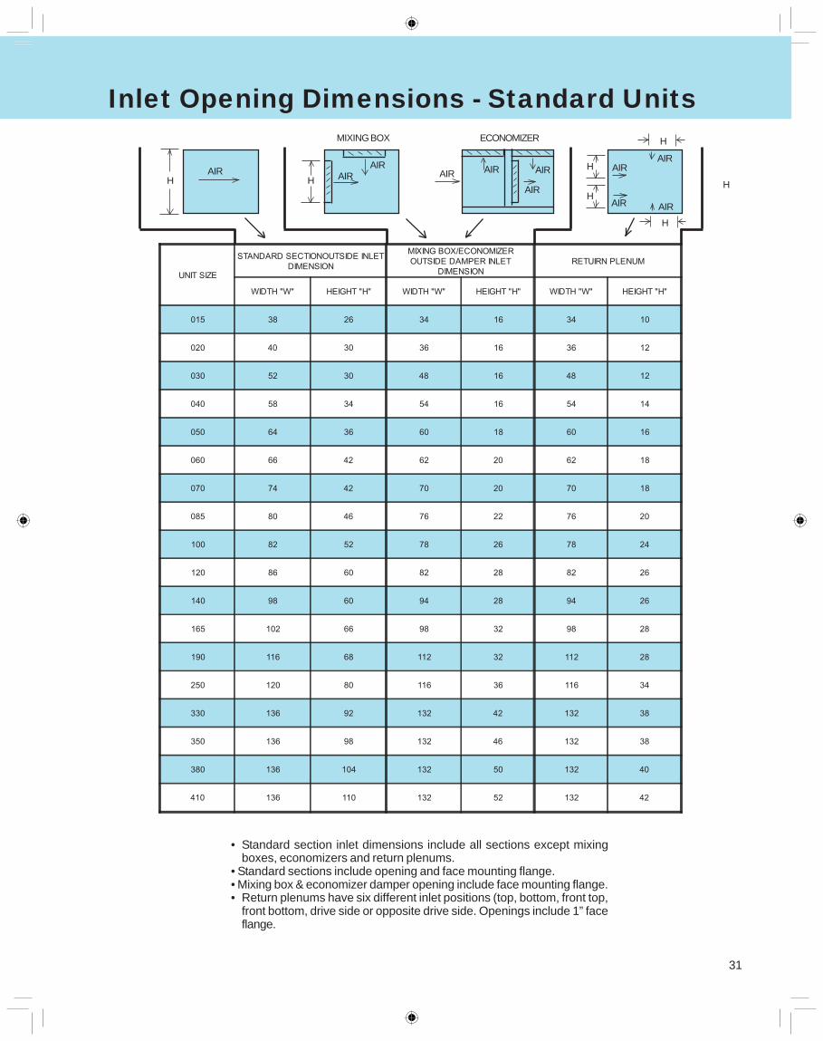
Inlet Opening Dimensions - Standard Units
HAIR
H AIRAIR
AIR AIR AIR
AIR
• Standard section inlet dimensions include all sections except mixingboxes, economizers and return plenums.
• Standard sections include opening and face mounting flange.• Mixing box & economizer damper opening include face mounting flange.• Return plenums have six different inlet positions (top, bottom, front top,
front bottom, drive side or opposite drive side. Openings include 1” faceflange.
H AIR
AIRH
AIR
AIR
MIXING BOX ECONOMIZER
H
H
H
32
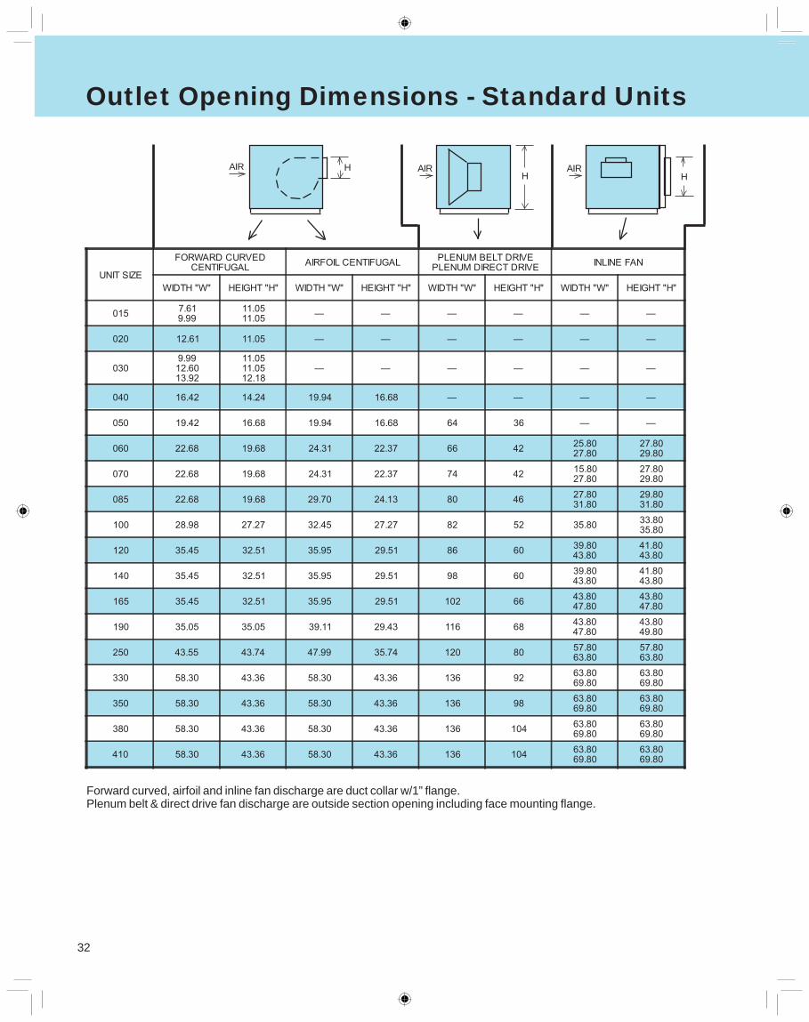
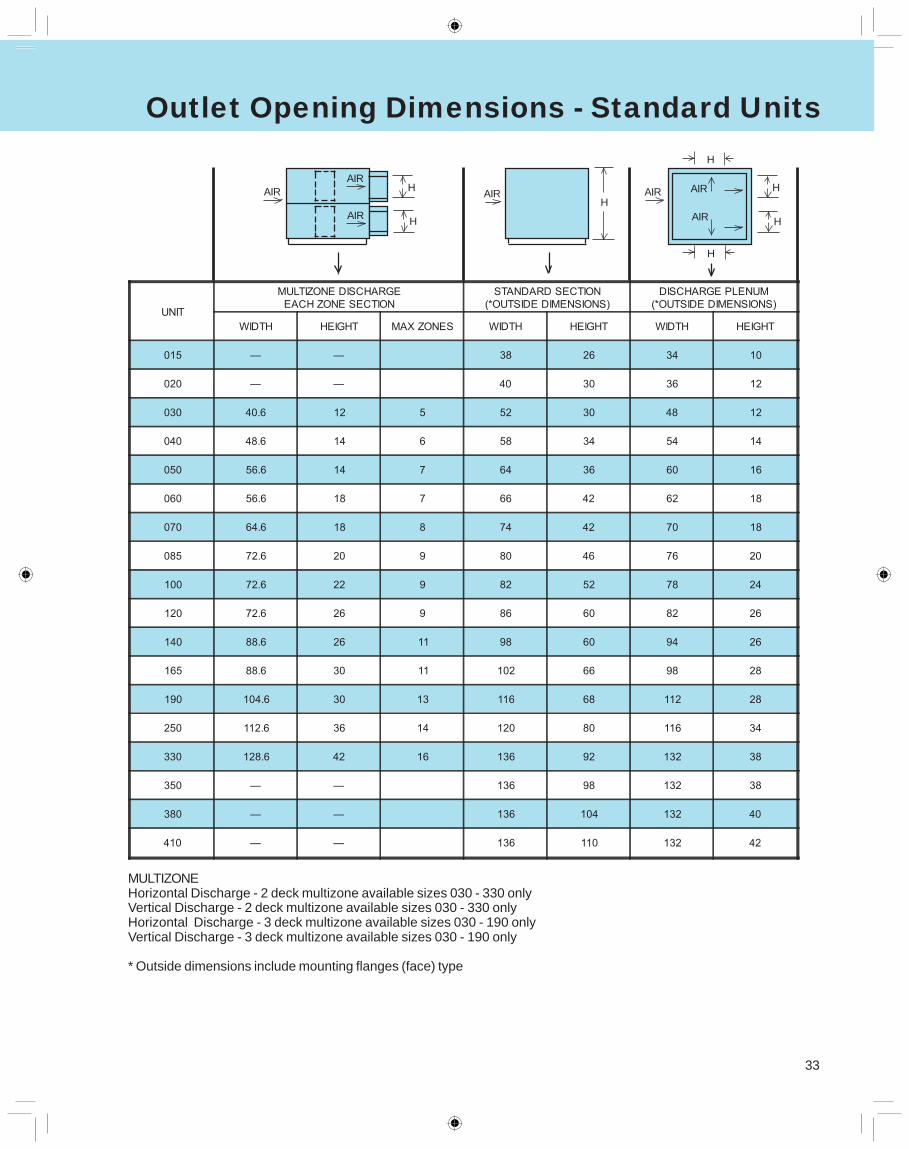
Outlet Opening Dimensions - Standard Units
HAIR
HAIRHAIR
Forward curved, airfoil and inline fan discharge are duct collar w/1” flange.Plenum belt & direct drive fan discharge are outside section opening including face mounting flange.
33
Outlet Opening Dimensions - Standard Units
MULTIZONEHorizontal Discharge - 2 deck multizone available sizes 030 - 330 onlyVertical Discharge - 2 deck multizone available sizes 030 - 330 onlyHorizontal Discharge - 3 deck multizone available sizes 030 - 190 onlyVertical Discharge - 3 deck multizone available sizes 030 - 190 only
* Outside dimensions include mounting flanges (face) type
AIR H
H
AIR
AIRH
AIR AIRAIR
AIR
H
H
AIR
AIR
H
H
34
35
USA Coil & Air Standard Material & Workmanship 1 Year Warranty
Basic Warranty - Material and Workmanship
Seller warrants, to the original buyer only, that any equipment manufactured by it will be free of defects in material andworkmanship, under normal use and service, for one year from date of shipment. Seller’s obligation under this warrantyshall be strictly and exclusively limited to repairing or replacing parts and materials, free of charge, f.o.b. our plant,which, in seller’s judgement are defective. Seller can’t control the environment nor the manner in which the equipment isused; therefore this warranty does not cover corrosion of equipment during use, or deterioration caused by conditions ofuse, or that applications of finishes supplied by others is sufficient, or that finishes applied are suitable for the Buyer’senvironment. Seller assumes no responsibility for reimbursing repair or replacement expenses incurred without its priorwritten authorization.
Buyer shall be responsible for all labor costs incurred in connection with such repair or replacement at installation site.Buyer shall also be responsible for all costs in removing, packing and shipping defective equipment back to seller. Sellershall be responsible for freight charges back to its factory and Buyer shall use the Seller’s designated means totransportation. It is the total responsibility of the Buyer to send back equipment samples quickly (it requested by Seller)to determine possible warranty claims.
Disclaimer of Warranties and Limitation of RemediesSeller makes no other warranties, expressed or implied with regard to goods and services provided by seller other thanthose set forth herein. Any implied warranty of merchantability or fitness for a particular purpose of buyer which exceedsthe foregoing warranty is hereby disclaimed by Seller.
Seller will not be liable for any direct or indirect consequential or incidental damages, losses or expenses, including, butnot limited to; commercial losses, business interruption, or damages resulting to property other than that which is thesubject of the sales transaction, nor shall Seller be liable for any personal injuries arising in connection with the sale,resale of operation of its goods or ability of the buyer to use the goods of Seller for any reason whatsoever.
Limitation of remedy here stated shall apply to ALL warranties arising out of the sale here subject. It is understoodbetween the parties that damage to the contents of the product herein vended, ineffectiveness of the product, or otherunintended consequences may result because of many factors including the manner of use of application of the product,all of which are beyond the control of Seller. All such risks shall be assumed by the Buyer. Seller’s maximum liabilityshall not, in any case, exceed the price of the goods claimed to be defective. Seller will not be liable for the infringementof any patents by the Buyer’s use of any materials delivered herein.
No promise, representation or affirmation of fact, written or oral, of the Seller or its agent or employees, other than asstated herein, shall constitute a warranty of seller or give rise of any liability or other obligation of Seller, unless specifi-cally agreed to in writing by Seller.
Basic Warranty