Embed Size (px)
Citation preview
US SL 380 MIDI 03-2016
1
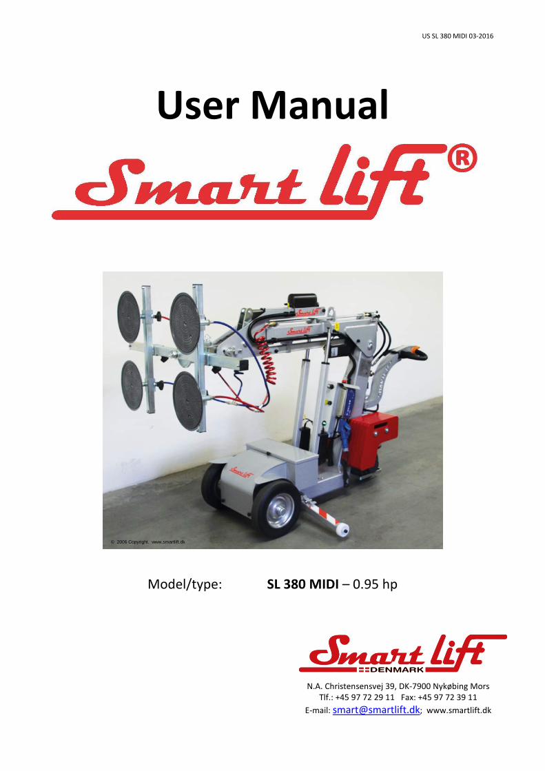
User Manual
Model/type: SL 380 MIDI – 0.95 hp
N.A. Christensensvej 39, DK-7900 Nykøbing Mors Tlf.: +45 97 72 29 11 Fax: +45 97 72 39 11
E-mail: [email protected]; www.smartlift.dk
© 2006 Copyright. www.smartlift.dk
US SL 380 MIDI 03-2016
2
Table of Contents: Table of Contents 2 Introduction 3 EU Declaration of Conformity 4 General Description 5 Transport/Handling/Putting into Operation/Storage 6 Technical Data, Safety Rules 7 Overview/ - General Description 8 Operation for Vacuum function 10 Control for arm and yoke 10 Important Operation (vacuum & electric functions) 11 Electric Functions 11 Charger & Battery Case 12 View of Vacuum system (top and bottom of machine) 13 Control Box 14 Switches and Alarms 14 Control Panel for arm and yoke 15 Load Diagram 16 Stop-Down Troubleshooting of SmartLIFT 17 - 26 Information and manual charger 27 Wiring Diagrams 29-31
US SL 380 MIDI 03-2016
3
Introduction Congratulations on your new SL 380 MIDI. Smart Lift has been designed and constructed so as to safeguard product users against accidents as far as at all possible. Unfortunately, certain functions in a machine cannot be safeguarded. This is why safety rules have been prepared by way of warnings in this instruction. Read these safety rules on the following pages before putting your Smart LIFT into operation, and imagine how you may, in your daily use of the machine, ensure that warnings and safety rules will be adhered to. Yours Sincerely, Nicolai T. Jørgensen Smartlift A/S N.A. Christensensvej 39 DK - 7900 Nykøbing Mors Telephone: +45 9772 2911 E-mail : [email protected] www.smartlift.dk
US SL 380 MIDI 03-2016
4
EU Declaration of Conformity Manufacturer Smartlift A/S N.A. Christensensvej 39 DK - 7900 Nykøbing Mors Hereby declares that: The machine/system: Lift Model/type: SL 380 MIDI – 0.95 hp Serial No.: Year/Month: 2016 has been made in conformity with Council directive
- Machine directive 2006/42EC - Low voltage directive 2006/95/EC + 2014/35/EU - EMC directive 2014/30/EU
The following standards have been applied: DS/EN ISO 12100 (Safety of machinery - General principles for design -- Risk assessment and risk reduction)
DS/EN ISO 14121-2 (Safety of machinery - Risk assessment -- Part 2: Practical guidance and examples of methods)
DS/EN ISO 13857 (Safety of machinery - Safety distances to prevent hazard zones being reached by upper and lower limbs)
DS/EN ISO 13849-1 (Safety of machinery - Safety-related parts of control systems - Part 1: General principles for design)
DS/EN 13155+A2 (Cranes - Safety - Non-fixed load lifting attachments)
DS/EN ISO 3691-1 (Industrial trucks - Safety requirements and verification - Part 1: Self-propelled industrial trucks, other than driverless trucks, variable-reach trucks and burden-carrier trucks)
DS/EN ISO 3691-5:2015 (Industrial trucks - Safety requirements and verification - Part 5: Pedestrian-propelled trucks)
DS/EN 60204-32 (Safety of machinery - Electrical equipment of machines - Part 32: Requirements for hoisting machines)
DS/EN ISO 13856-3 (Safety of machinery - Pressure-sensitive protective devices - Part 3: General principles for design and testing of pressure-sensitive bumpers, plates, wires and similar devices)
Date: Signature: ____________ ____________________________________ Nicolai T. Jørgensen, Director
US SL 380 MIDI 03-2016
5
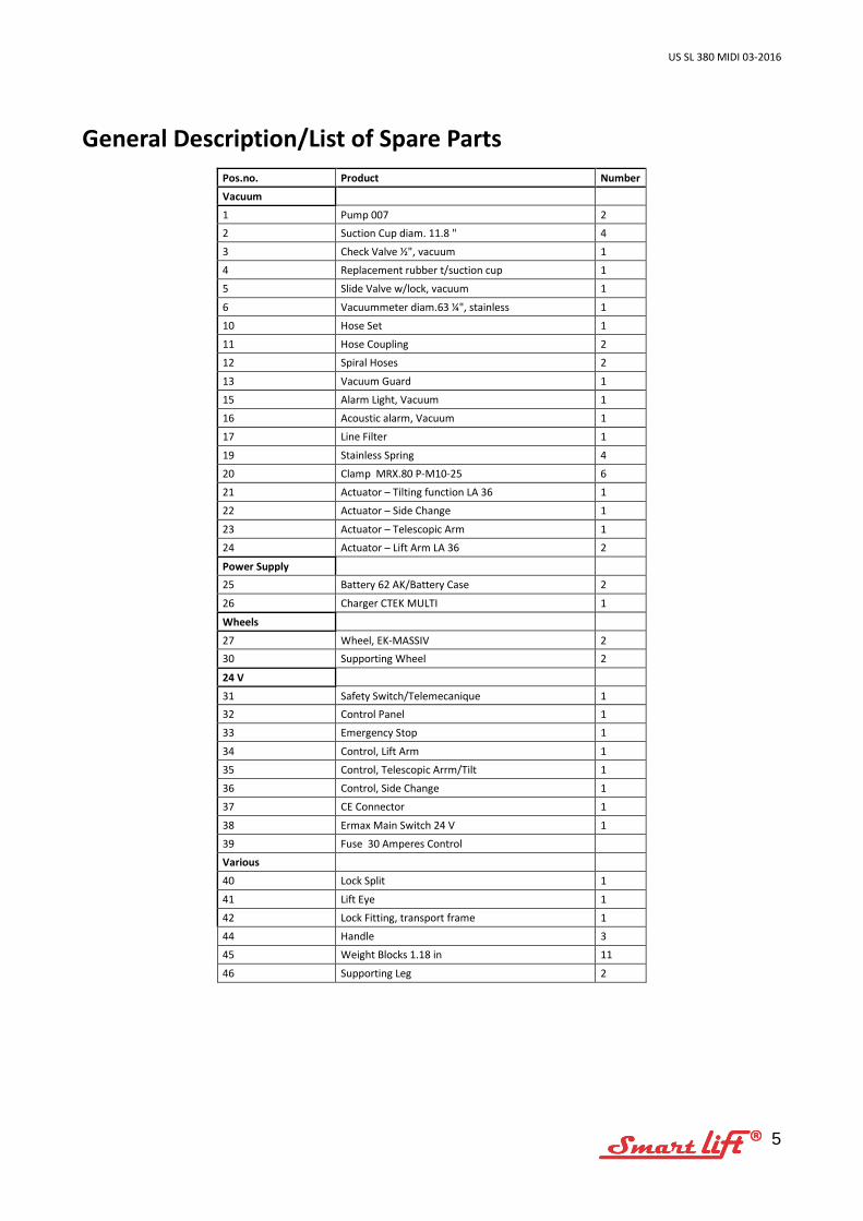
General Description/List of Spare Parts
Pos.no. Product Number
Vacuum
1 Pump 007 2 2 Suction Cup diam. 11.8 " 4
3 Check Valve ½", vacuum 1
4 Replacement rubber t/suction cup 1
5 Slide Valve w/lock, vacuum 1
6 Vacuummeter diam.63 ¼", stainless 1
10 Hose Set 1
11 Hose Coupling 2
12 Spiral Hoses 2
13 Vacuum Guard 1
15 Alarm Light, Vacuum 1
16 Acoustic alarm, Vacuum 1
17 Line Filter 1
19 Stainless Spring 4
20 Clamp MRX.80 P-M10-25 6
21 Actuator – Tilting function LA 36 1
22 Actuator – Side Change 1
23 Actuator – Telescopic Arm 1
24 Actuator – Lift Arm LA 36 2
Power Supply 25 Battery 62 AK/Battery Case 2
26 Charger CTEK MULTI 1
Wheels
27 Wheel, EK-MASSIV 2 30 Supporting Wheel 2
24 V
31 Safety Switch/Telemecanique 1 32 Control Panel 1
33 Emergency Stop 1
34 Control, Lift Arm 1
35 Control, Telescopic Arrm/Tilt 1
36 Control, Side Change 1
37 CE Connector 1
38 Ermax Main Switch 24 V 1
39 Fuse 30 Amperes Control
Various
40 Lock Split 1
41 Lift Eye 1
42 Lock Fitting, transport frame 1
44 Handle 3
45 Weight Blocks 1.18 in 11
46 Supporting Leg 2
US SL 380 MIDI 03-2016
6
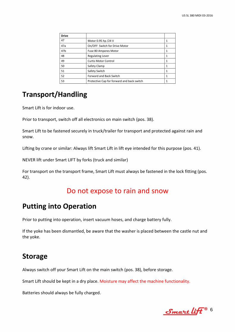
Drive 47 48
Motor 0.95 hp /24 V 1
47a On/OFF Switch for Drive Motor 1
47b Fuse 80 Amperes Motor 1
48 Regulating Lever 1
49 Curtis Motor Control 1
50 Safety Clamp 1
51 Safety Switch 1
52 Forward and Back Switch 1
53 Protective Cap for forward and back switch 1
Transport/Handling Smart Lift is for indoor use. Prior to transport, switch off all electronics on main switch (pos. 38). Smart Lift to be fastened securely in truck/trailer for transport and protected against rain and snow. Lifting by crane or similar: Always lift Smart Lift in lift eye intended for this purpose (pos. 41).
NEVER lift under Smart LIFT by forks (truck and similar) For transport on the transport frame, Smart Lift must always be fastened in the lock fitting (pos. 42).
Do not expose to rain and snow
Putting into Operation Prior to putting into operation, insert vacuum hoses, and charge battery fully. If the yoke has been dismantled, be aware that the washer is placed between the castle nut and the yoke.
Storage Always switch off your Smart Lift on the main switch (pos. 38), before storage. Smart Lift should be kept in a dry place. Moisture may affect the machine functionality. Batteries should always be fully charged.
US SL 380 MIDI 03-2016
7
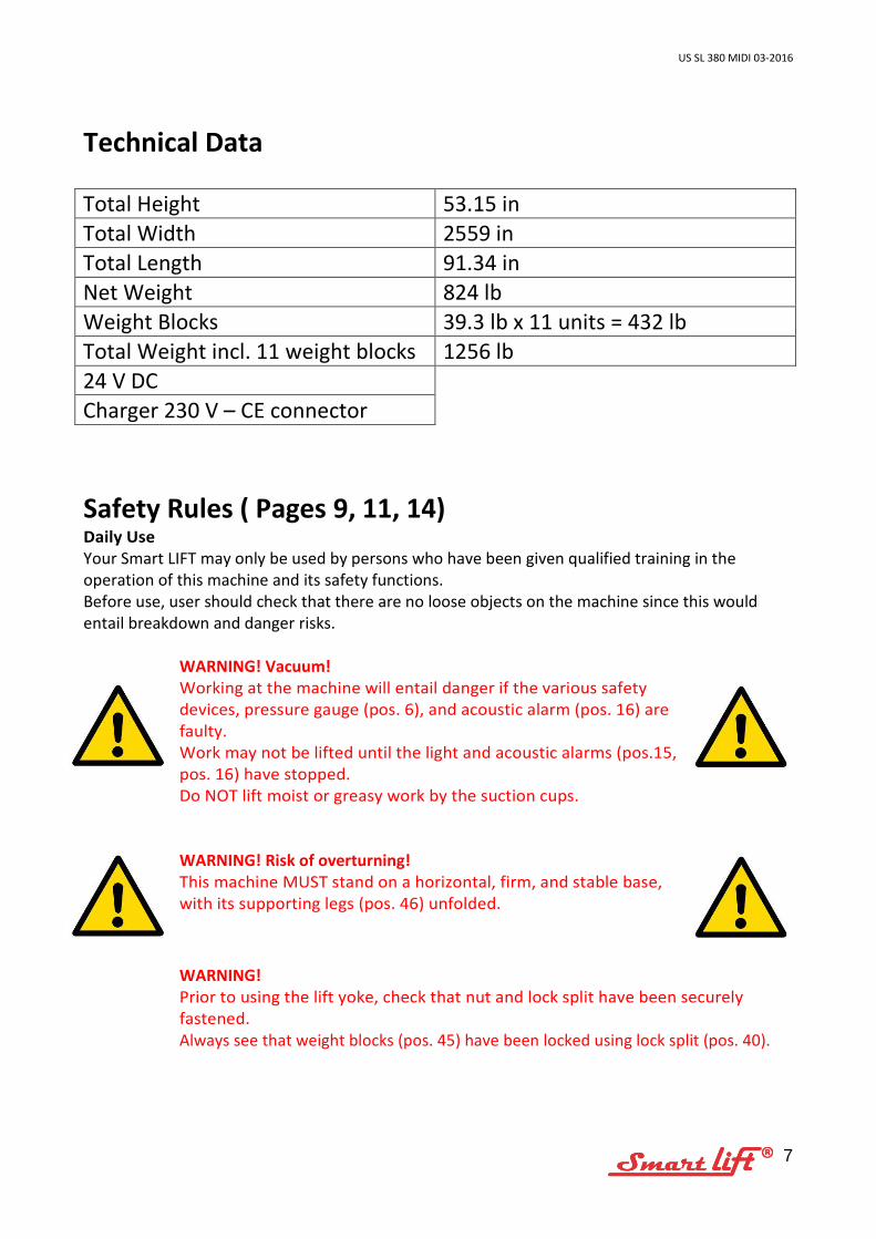
Technical Data Total Height 53.15 in Total Width 2559 in Total Length 91.34 in Net Weight 824 lb Weight Blocks 39.3 lb x 11 units = 432 lb Total Weight incl. 11 weight blocks 1256 lb 24 V DC Charger 230 V – CE connector Safety Rules ( Pages 9, 11, 14) Daily Use Your Smart LIFT may only be used by persons who have been given qualified training in the operation of this machine and its safety functions. Before use, user should check that there are no loose objects on the machine since this would entail breakdown and danger risks.
WARNING! Vacuum! Working at the machine will entail danger if the various safety devices, pressure gauge (pos. 6), and acoustic alarm (pos. 16) are faulty. Work may not be lifted until the light and acoustic alarms (pos.15, pos. 16) have stopped. Do NOT lift moist or greasy work by the suction cups.
WARNING! Risk of overturning! This machine MUST stand on a horizontal, firm, and stable base, with its supporting legs (pos. 46) unfolded.
WARNING! Prior to using the lift yoke, check that nut and lock split have been securely fastened. Always see that weight blocks (pos. 45) have been locked using lock split (pos. 40).
US SL 380 MIDI 03-2016
8
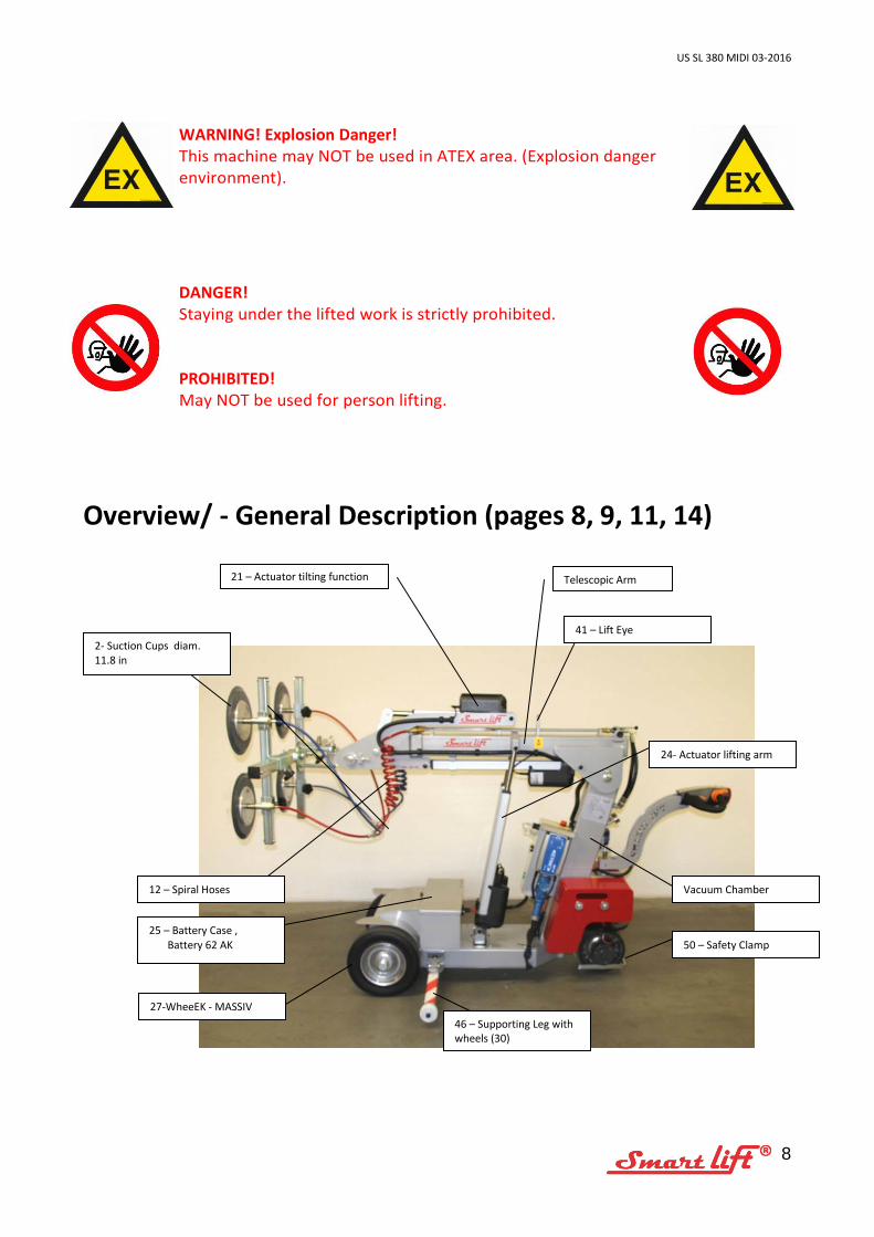
WARNING! Explosion Danger! This machine may NOT be used in ATEX area. (Explosion danger environment).
DANGER! Staying under the lifted work is strictly prohibited.
PROHIBITED! May NOT be used for person lifting.
Overview/ - General Description (pages 8, 9, 11, 14)
Telescopic Arm 21 – Actuator tilting function
2- Suction Cups diam. 11.8 in
Vacuum Chamber
25 – Battery Case , Battery 62 AK
12 – Spiral Hoses
46 – Supporting Leg with wheels (30)
41 – Lift Eye
50 – Safety Clamp
24- Actuator lifting arm
27-WheeEK - MASSIV
US SL 380 MIDI 03-2016
9
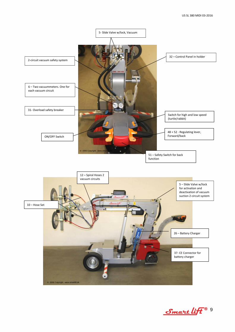
51 – Safety Switch for back function
26 – Battery Charger
37- CE Connector for battery charger
10 – Hose Set
2-circuit vacuum safety system
5 – Slide Valve w/lock for activation and deactivation of vacuum suction 2-circuit system
32 – Control Panel in holder
5- Slide Valve w/lock, Vacuum
© 2006 Copyright. www.smartlift.dk
© 2006 Copyright. www.smartlift.dk
31- Overload safety breaker
6 – Two vacuummeters. One for each vacuum circuit
ON/OFF Switch
Switch for high and low speed (turtle/rabbit)
48 + 52 - Regulating lever, Forward/back
12 – Spiral Hoses 2 vacuum circuits
US SL 380 MIDI 03-2016
10
Operation of VACUUM function: (page 13) This function (pos. 5) will switch vacuum on and off. The vacuum pump is controlled by a vacustat. The pump starts at -0,53 and stops at -0,62. The vacuum function is operated by the slide valve and safety button on top of the arm. To activate vacuum push the slide valve forward. To deactivate vacuum pull out the safety button and pull back the handle on the slide valve.
Control Panel (pos. 32) for arm and yoke: (pages 8, 9, 15) Users should make a point of reading the function description below, so as to become familiar with the functioning of the machine. Smart LIFT is operated manually. This machine generally has four functions which may be operated individually. UP/DOWN function: This function will make the arm move either up or down. The movement is made via the actuators, (pos. 24). TILTING function: This function will make the work turn round. The movement is made by actuator, (pos. 21). TELESCOPIC ARM function: The movement is made via actuator, placed under the lift arm, (pos. 23). SIDE DISPLACEMENT function: This movement is performed via actuator, placed between the two front wheels. (pos. 22).
Electric functions: (pages 9, 11, 14) STOP/EMERGENCY STOP function: The emergency stop button (pos. 33) is placed on the actual control panel. This button will switch off actuators, electric control, as well as drive motor.
US SL 380 MIDI 03-2016
11
MAIN SWITCH: (Pos. 38) Placed on the battery case inside. Turn handle to switch off all electric functions. DRIVE MOTOR, (pos. 47): The drive motor is activated by an on/off switch (pos. 47a). Then turn the regulating lever (pos. 48). FORWARD AND BACK function, (pos. 52): Toggle switch forward and back SAFETY function, (pos. 51): Activating the safety switch will stop the car, and the car will move forward.
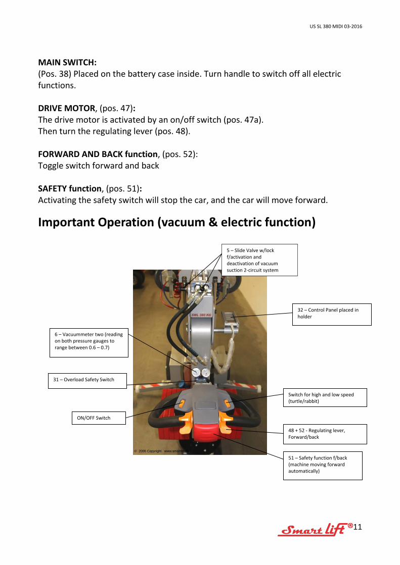
Important Operation (vacuum & electric function)
51 – Safety function f/back (machine moving forward automatically)
32 – Control Panel placed in holder
31 – Overload Safety Switch
6 – Vacuummeter two (reading on both pressure gauges to range between 0.6 – 0.7)
5 – Slide Valve w/lock f/activation and deactivation of vacuum suction 2-circuit system
© 2006 Copyright. www.smartlift.dk
48 + 52 - Regulating lever, Forward/back
Switch for high and low speed (turtle/rabbit)
ON/OFF Switch
US SL 380 MIDI 03-2016
12
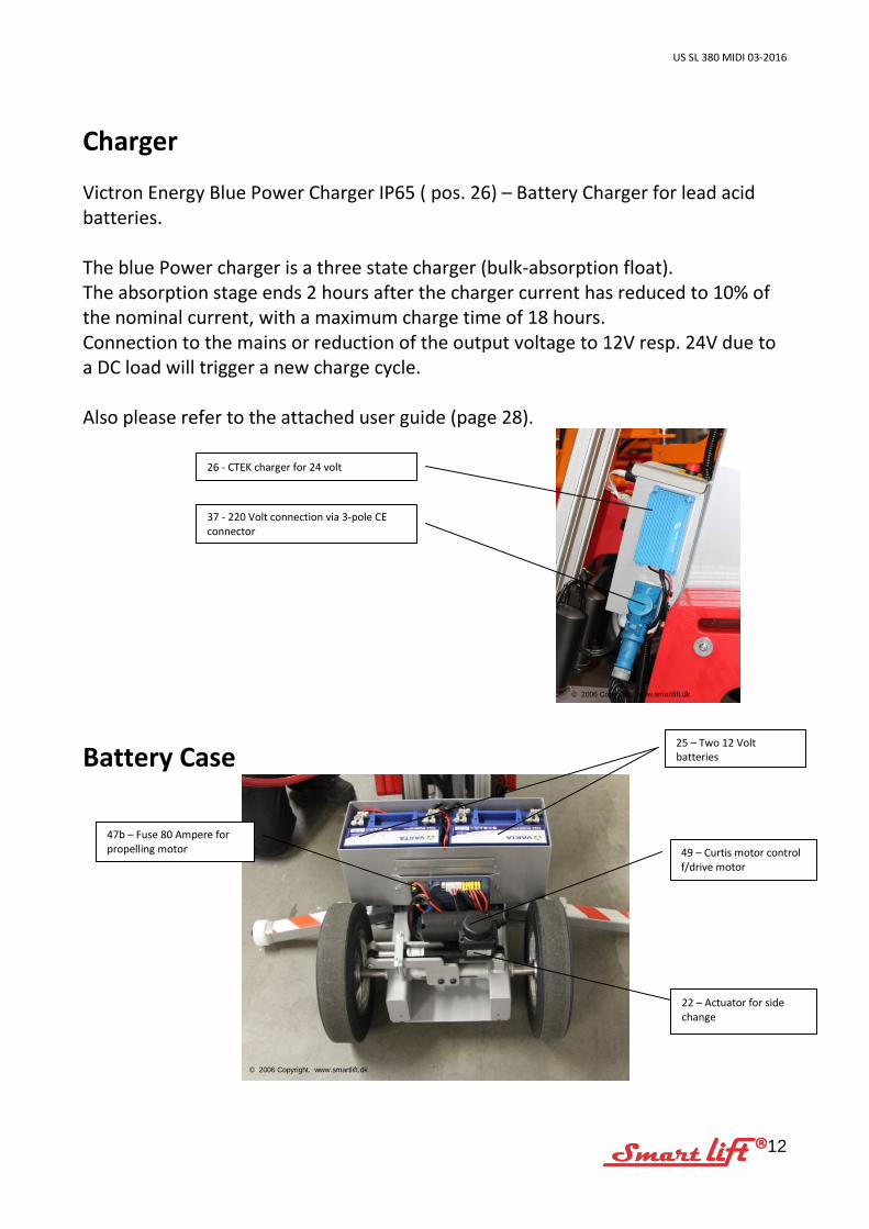
Charger Victron Energy Blue Power Charger IP65 ( pos. 26) – Battery Charger for lead acid batteries. The blue Power charger is a three state charger (bulk-absorption float). The absorption stage ends 2 hours after the charger current has reduced to 10% of the nominal current, with a maximum charge time of 18 hours. Connection to the mains or reduction of the output voltage to 12V resp. 24V due to a DC load will trigger a new charge cycle. Also please refer to the attached user guide (page 28).
Battery Case
49 – Curtis motor control f/drive motor
47b – Fuse 80 Ampere for propelling motor
25 – Two 12 Volt batteries
26 - CTEK charger for 24 volt
37 - 220 Volt connection via 3-pole CE connector
22 – Actuator for side change
© 2006 Copyright. www.smartlift.dk
© 2006 Copyright. www.smartlift.dk
US SL 380 MIDI 03-2016
13
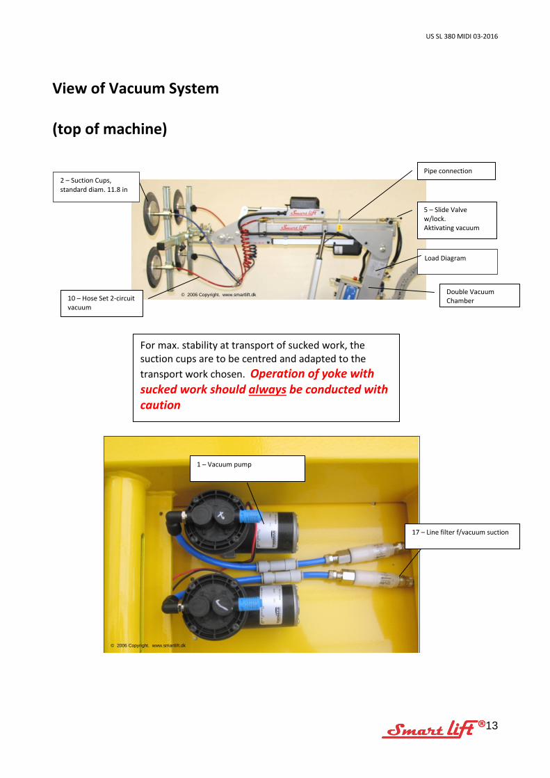
View of Vacuum System (top of machine)
10 – Hose Set 2-circuit vacuum
Double Vacuum Chamber
Pipe connection
5 – Slide Valve w/lock. Aktivating vacuum
Load Diagram
© 2006 Copyright. www.smartlift.dk
17 – Line filter f/vacuum suction
1 – Vacuum pump
© 2006 Copyright. www.smartlift.dk
For max. stability at transport of sucked work, the suction cups are to be centred and adapted to the transport work chosen. Operation of yoke with sucked work should always be conducted with caution
2 – Suction Cups, standard diam. 11.8 in
US SL 380 MIDI 03-2016
14
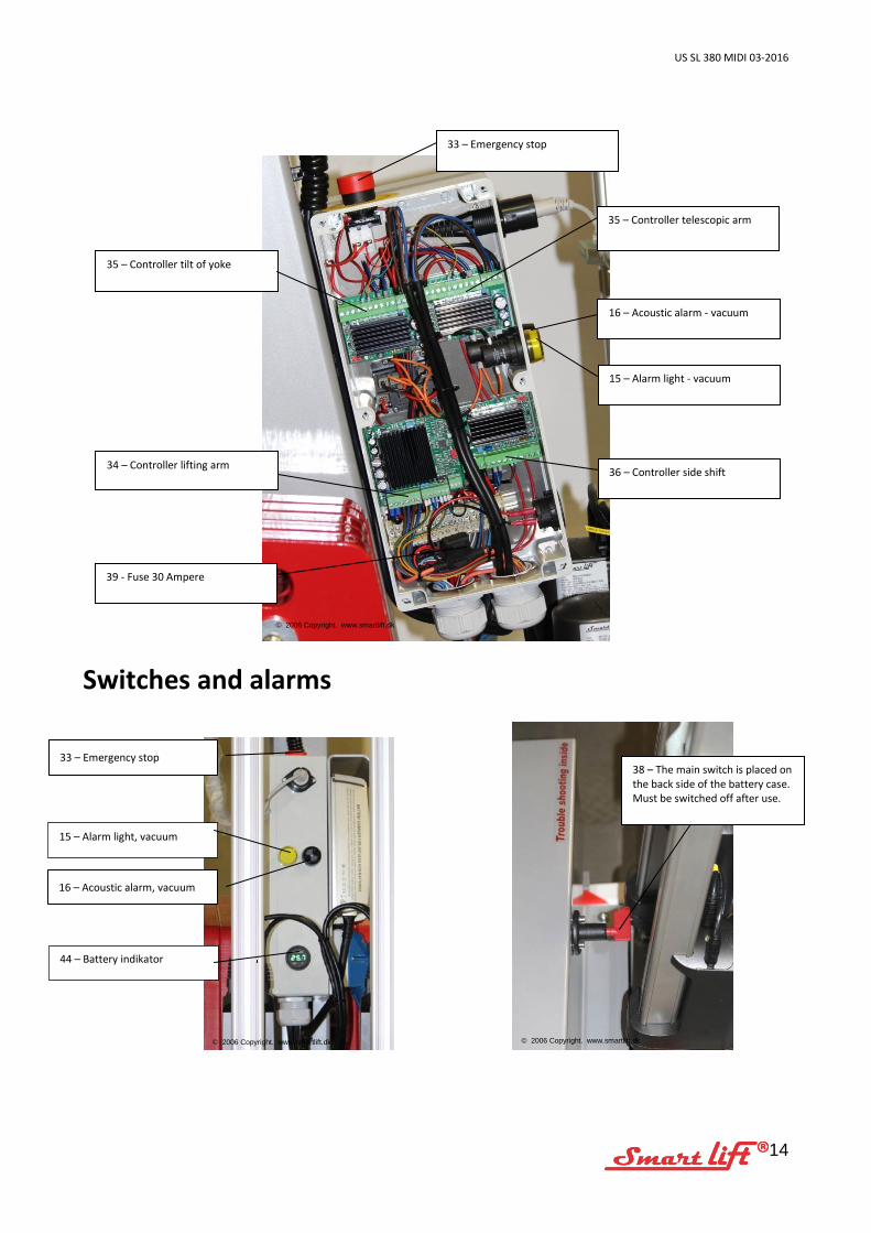
Switches and alarms
16 – Acoustic alarm, vacuum
33 – Emergency stop
44 – Battery indikator
38 – The main switch is placed on the back side of the battery case. Must be switched off after use.
© 2006 Copyright. www.smartlift.dk
© 2006 Copyright. www.smartlift.dk
34 – Controller lifting arm
39 - Fuse 30 Ampere
36 – Controller side shift
35 – Controller telescopic arm
15 – Alarm light - vacuum
16 – Acoustic alarm - vacuum
33 – Emergency stop
35 – Controller tilt of yoke
© 2006 Copyright. www.smartlift.dk
15 – Alarm light, vacuum
US SL 380 MIDI 03-2016
15
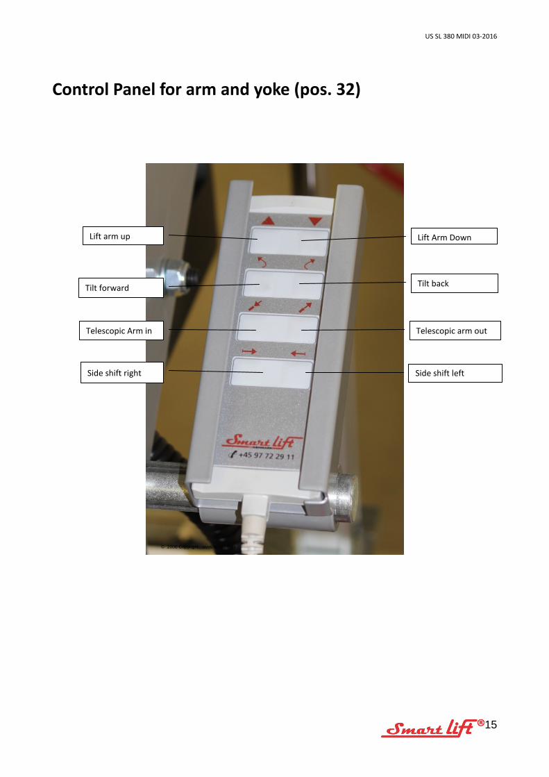
Control Panel for arm and yoke (pos. 32)
Lift Arm Down
Tilt back
Telescopic arm out
Side shift left
Lift arm up
Tilt forward
Telescopic Arm in
Side shift right
© 2006 Copyright. www.smartlift.dk
US SL 380 MIDI 03-2016
16
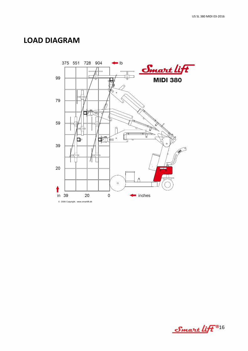
LOAD DIAGRAM
© 2006 Copyright. www.smartlift.dk
US SL 380 MIDI 03-2016
17
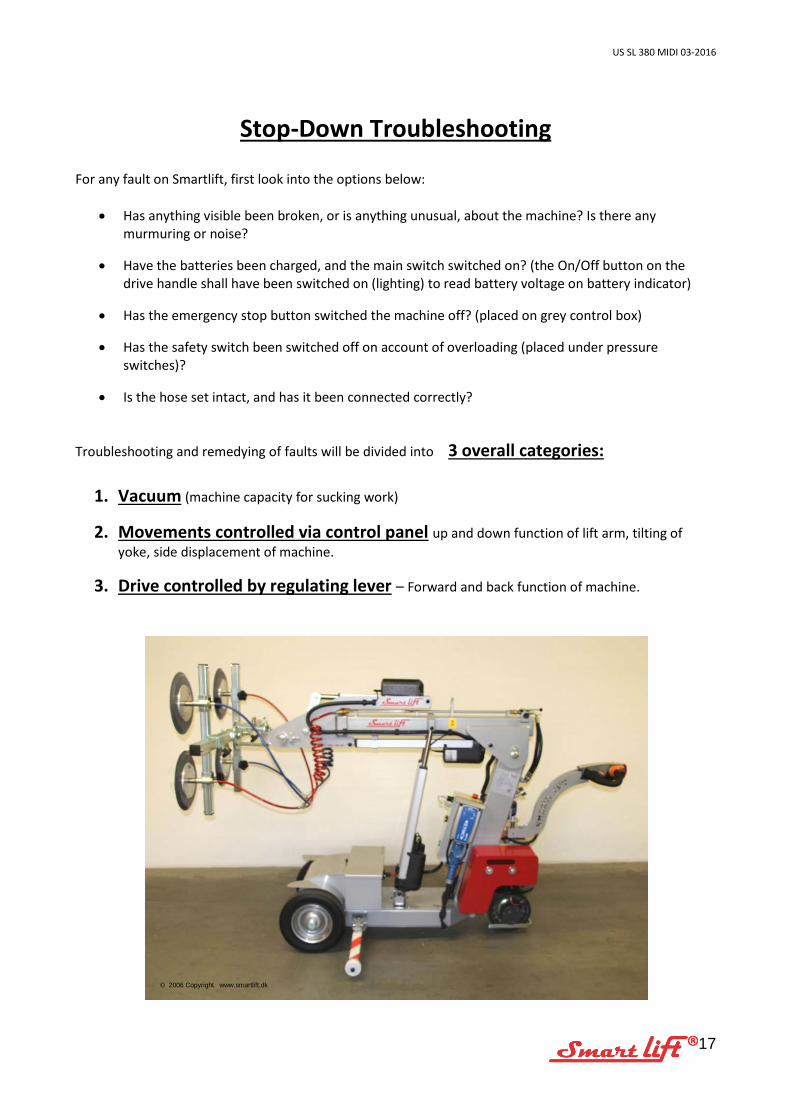
Stop-Down Troubleshooting For any fault on Smartlift, first look into the options below:
• Has anything visible been broken, or is anything unusual, about the machine? Is there any murmuring or noise?
• Have the batteries been charged, and the main switch switched on? (the On/Off button on the drive handle shall have been switched on (lighting) to read battery voltage on battery indicator)
• Has the emergency stop button switched the machine off? (placed on grey control box)
• Has the safety switch been switched off on account of overloading (placed under pressure switches)?
• Is the hose set intact, and has it been connected correctly?
Troubleshooting and remedying of faults will be divided into 3 overall categories:
1. Vacuum (machine capacity for sucking work)
2. Movements controlled via control panel up and down function of lift arm, tilting of yoke, side displacement of machine.
3. Drive controlled by regulating lever – Forward and back function of machine.
© 2006 Copyright. www.smartlift.dk
US SL 380 MIDI 03-2016
18
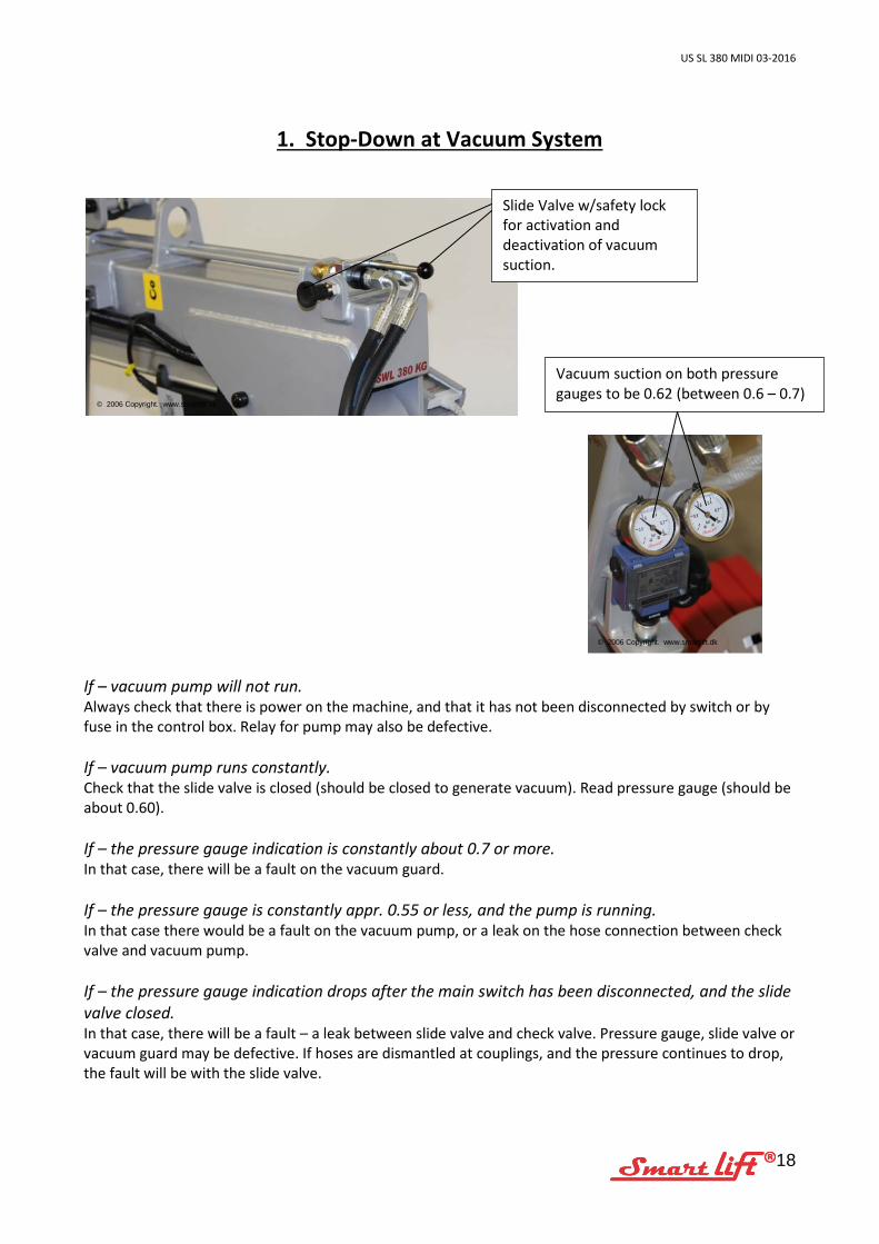
1. Stop-Down at Vacuum System
If – vacuum pump will not run. Always check that there is power on the machine, and that it has not been disconnected by switch or by fuse in the control box. Relay for pump may also be defective. If – vacuum pump runs constantly. Check that the slide valve is closed (should be closed to generate vacuum). Read pressure gauge (should be about 0.60). If – the pressure gauge indication is constantly about 0.7 or more. In that case, there will be a fault on the vacuum guard. If – the pressure gauge is constantly appr. 0.55 or less, and the pump is running. In that case there would be a fault on the vacuum pump, or a leak on the hose connection between check valve and vacuum pump. If – the pressure gauge indication drops after the main switch has been disconnected, and the slide valve closed. In that case, there will be a fault – a leak between slide valve and check valve. Pressure gauge, slide valve or vacuum guard may be defective. If hoses are dismantled at couplings, and the pressure continues to drop, the fault will be with the slide valve.
Slide Valve w/safety lock for activation and deactivation of vacuum suction.
Vacuum suction on both pressure gauges to be 0.62 (between 0.6 – 0.7)
© 2006 Copyright. www.smartlift.dk
© 2006 Copyright. www.smartlift.dk
US SL 380 MIDI 03-2016
19
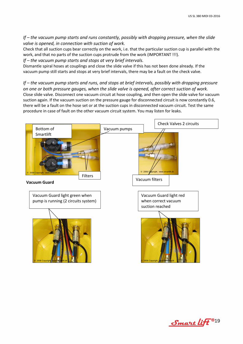
If – the vacuum pump starts and runs constantly, possibly with dropping pressure, when the slide valve is opened, in connection with suction of work. Check that all suction cups bear correctly on the work, i.e. that the particular suction cup is parallel with the work, and that no parts of the suction cups protrude from the work (IMPORTANT !!!). If – the vacuum pump starts and stops at very brief intervals. Dismantle spiral hoses at couplings and close the slide valve if this has not been done already. If the vacuum pump still starts and stops at very brief intervals, there may be a fault on the check valve. If – the vacuum pump starts and runs, and stops at brief intervals, possibly with dropping pressure on one or both pressure gauges, when the slide valve is opened, after correct suction of work. Close slide valve. Disconnect one vacuum circuit at hose coupling, and then open the slide valve for vacuum suction again. If the vacuum suction on the pressure gauge for disconnected circuit is now constantly 0.6, there will be a fault on the hose set or at the suction cups in disconnected vacuum circuit. Test the same procedure in case of fault on the other vacuum circuit system. You may listen for leaks.
Vacuum Guard
Bottom of Smartlift
Vacuum pumps Check Valves 2 circuits
Vacuum Guard light green when pump is running (2 circuits system)
Vacuum Guard light red when correct vacuum suction reached
Filters
© 2006 Copyright. www.smartlift.dk
© 2006 Copyright. www.smartlift.dk
© 2006 Copyright. www.smartlift.dk
© 2006 Copyright. www.smartlift.dk
Vacuum filters
US SL 380 MIDI 03-2016
20
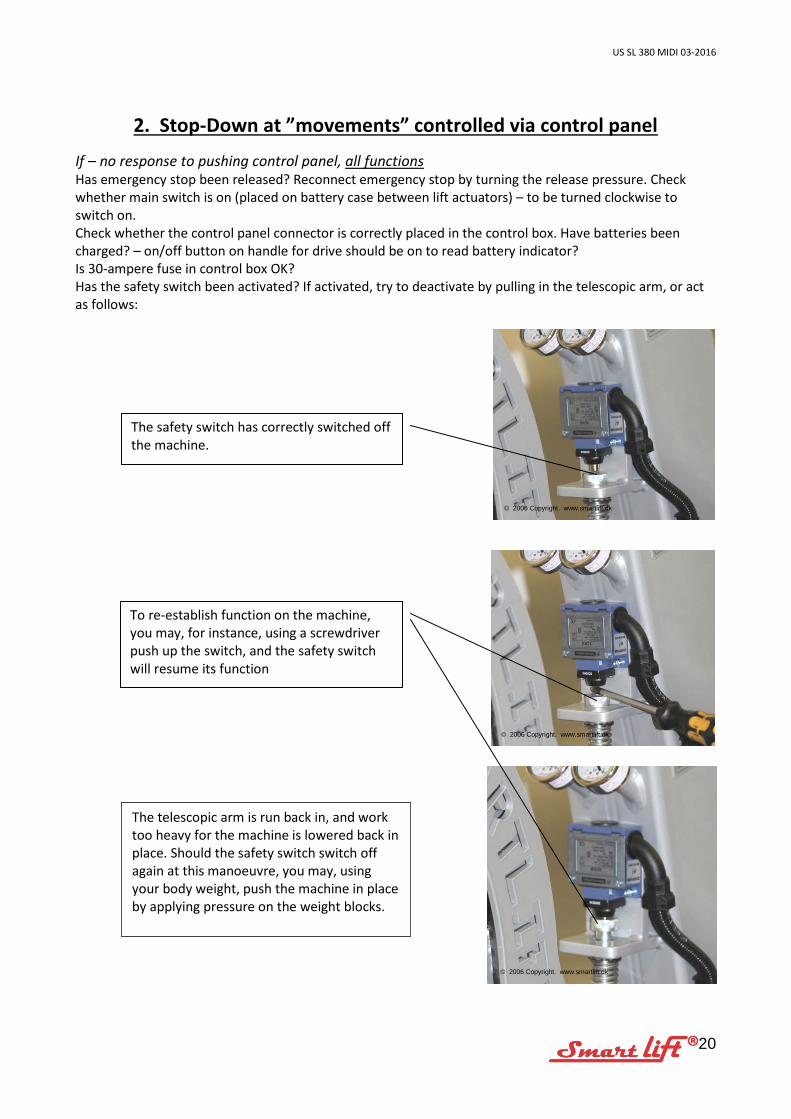
2. Stop-Down at ”movements” controlled via control panel
If – no response to pushing control panel, all functions Has emergency stop been released? Reconnect emergency stop by turning the release pressure. Check whether main switch is on (placed on battery case between lift actuators) – to be turned clockwise to switch on. Check whether the control panel connector is correctly placed in the control box. Have batteries been charged? – on/off button on handle for drive should be on to read battery indicator? Is 30-ampere fuse in control box OK? Has the safety switch been activated? If activated, try to deactivate by pulling in the telescopic arm, or act as follows:
The safety switch has correctly switched off the machine.
To re-establish function on the machine, you may, for instance, using a screwdriver push up the switch, and the safety switch will resume its function
The telescopic arm is run back in, and work too heavy for the machine is lowered back in place. Should the safety switch switch off again at this manoeuvre, you may, using your body weight, push the machine in place by applying pressure on the weight blocks.
© 2006 Copyright. www.smartlift.dk
© 2006 Copyright. www.smartlift.dk
© 2006 Copyright. www.smartlift.dk
US SL 380 MIDI 03-2016
21
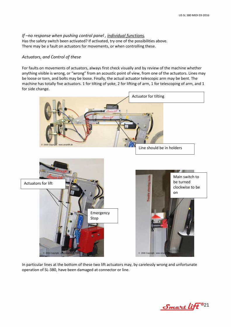
If –no response when pushing control panel , individual functions, Has the safety switch been activated? If activated, try one of the possibilities above. There may be a fault on actuators for movements, or when controlling these. Actuators, and Control of these For faults on movements of actuators, always first check visually and by review of the machine whether anything visible is wrong, or “wrong” from an acoustic point of view, from one of the actuators. Lines may be loose or torn, and bolts may be loose. Finally, the actual actuator telescopic arm may be bent. The machine has totally five actuators. 1 for tilting of yoke, 2 for lifting of arm, 1 for telescoping of arm, and 1 for side change.
In particular lines at the bottom of these two lift actuators may, by carelessly wrong and unfortunate operation of SL-380, have been damaged at connector or line.
Actuator for tilting
Actuators for lift
Emergency Stop
Main switch to be turned clockwise to be on
© 2006 Copyright. www.smartlift.dk
© 2006 Copyright. www.smartlift.dk
© 2006 Copyright. www.smartlift.dk
Line should be in holders
US SL 380 MIDI 03-2016
22
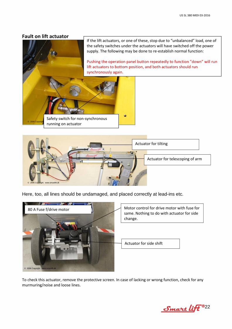
Fault on lift actuator
Here, too, all lines should be undamaged, and placed correctly at lead-ins etc.
To check this actuator, remove the protective screen. In case of lacking or wrong function, check for any murmuring/noise and loose lines.
Actuator for telescoping of arm
Actuator for side shift
Motor control for drive motor with fuse for same. Nothing to do with actuator for side change.
80 A Fuse f/drive motor
If the lift actuators, or one of these, stop due to “unbalanced” load, one of the safety switches under the actuators will have switched off the power supply. The following may be done to re-establish normal function: Pushing the operation panel button repeatedly to function ”down” will run lift actuators to bottom position, and both actuators should run synchronously again.
© 2006 Copyright. www.smartlift.dk
© 2006 Copyright. www.smartlift.dk
© 2006 Copyright. www.smartlift.dk
Actuator for tilting
Safety switch for non-synchronous running on actuator
US SL 380 MIDI 03-2016
23
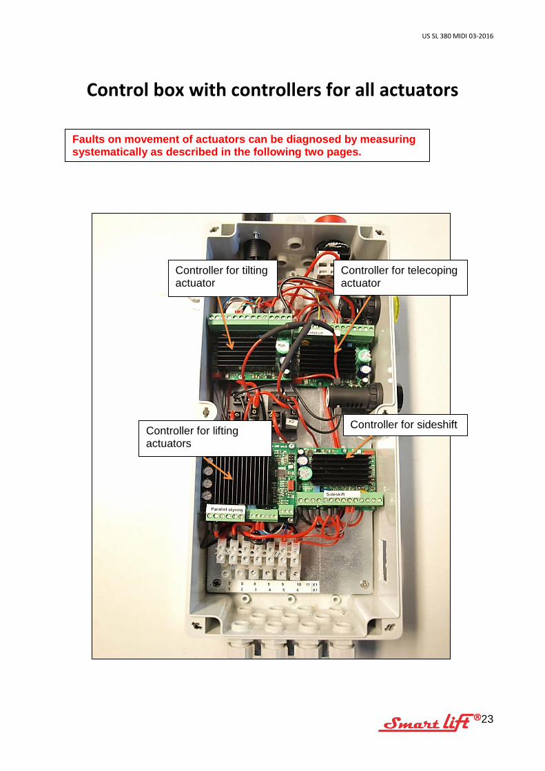
Control box with controllers for all actuators
Faults on movement of actuators can be diagnosed by measuring systematically as described in the following two pages.
Controller for tilting actuator
Controller for telecoping actuator
Controller for lifting actuators
Controller for sideshift
US SL 380 MIDI 03-2016
24
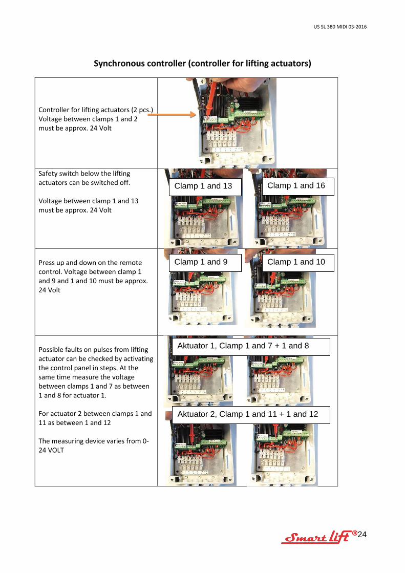
Synchronous controller (controller for lifting actuators)
Controller for lifting actuators (2 pcs.) Voltage between clamps 1 and 2 must be approx. 24 Volt
Safety switch below the lifting actuators can be switched off. Voltage between clamp 1 and 13 must be approx. 24 Volt
Press up and down on the remote control. Voltage between clamp 1 and 9 and 1 and 10 must be approx. 24 Volt
Possible faults on pulses from lifting actuator can be checked by activating the control panel in steps. At the same time measure the voltage between clamps 1 and 7 as between 1 and 8 for actuator 1. For actuator 2 between clamps 1 and 11 as between 1 and 12 The measuring device varies from 0-24 VOLT
Clamp 1 and 13 Clamp 1 and 16
Clamp 1 and 10 Clamp 1 and 9
Aktuator 1, Clamp 1 and 7 + 1 and 8
Aktuator 2, Clamp 1 and 11 + 1 and 12
US SL 380 MIDI 03-2016
25
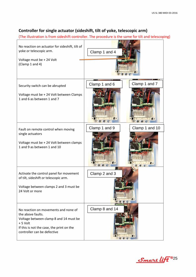
Controller for single actuator (sideshift, tilt of yoke, telescopic arm) (The illustration is from sideshift controller. The procedure is the same for tilt and telescoping) No reaction on actuator for sideshift, tilt of yoke or telescopic arm. Voltage must be + 24 Volt (Clamp 1 and 4)
Security switch can be abrupted Voltage must be + 24 Volt between Clamps 1 and 6 as between 1 and 7
Fault on remote control when moving single actuators Voltage must be + 24 Volt between clamps 1 and 9 as between 1 and 10
Activate the control panel for movement of tilt, sideshift or telescopic arm. Voltage between clamps 2 and 3 must be 24 Volt or more
No reaction on movements and none of the above faults. Voltage between clamp 8 and 14 must be + 5 Volt If this is not the case, the print on the controller can be defective
Clamp 1 and 4
Clamp 1 and 6 Clamp 1 and 7
Clamp 1 and 9 Clamp 1 and 10
Clamp 2 and 3
Clamp 8 and 14
US SL 380 MIDI 03-2016
26
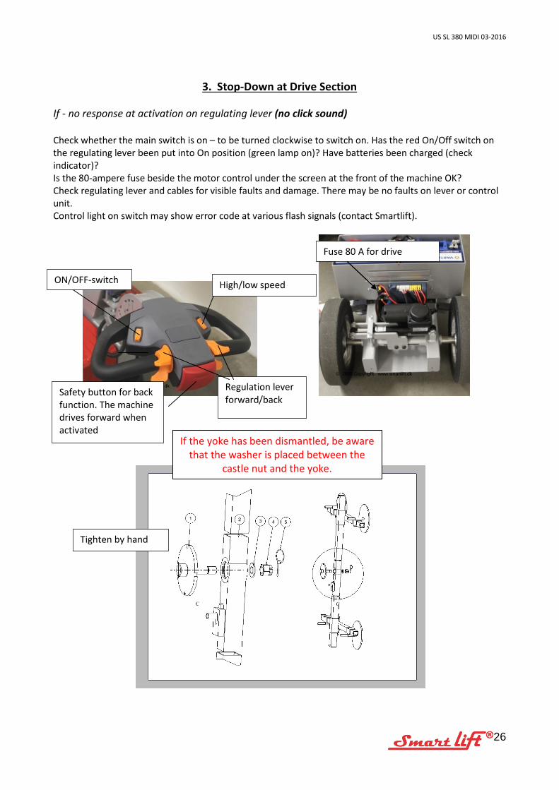
3. Stop-Down at Drive Section If - no response at activation on regulating lever (no click sound) Check whether the main switch is on – to be turned clockwise to switch on. Has the red On/Off switch on the regulating lever been put into On position (green lamp on)? Have batteries been charged (check indicator)? Is the 80-ampere fuse beside the motor control under the screen at the front of the machine OK? Check regulating lever and cables for visible faults and damage. There may be no faults on lever or control unit. Control light on switch may show error code at various flash signals (contact Smartlift).
Fuse 80 A for drive
© 2006 Copyright. www.smartlift.dk
© 2006 Copyright. www.smartlift.dk
Regulation lever forward/back
High/low speed
Safety button for back function. The machine drives forward when activated
If the yoke has been dismantled, be aware
that the washer is placed between the castle nut and the yoke.
Tighten by hand
ON/OFF-switch

US SL 380 MIDI 03-2016
27
Battery Charger Victron Energy - Blue Power Charger IP65
For complete manual refer to: https://www.victronenergy.com/upload/documents/Datasheet-Blue-Power-Battery-Charger-IP65-90-135VAC-EN.pdf
LED indication Description Yellow LED on: battery being charged. Yellow LED on and green LED on: absorption charge. Green LED on: battery fully charged, float charge.
US SL 380 MIDI 03-2016
28
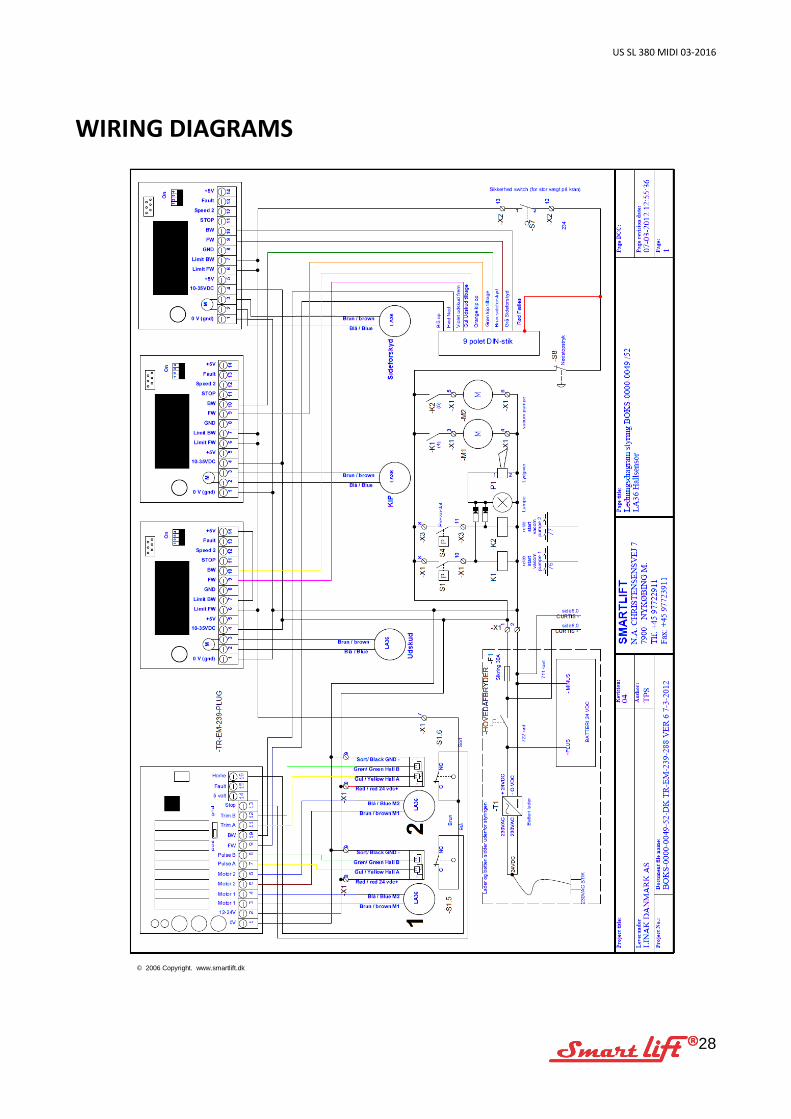
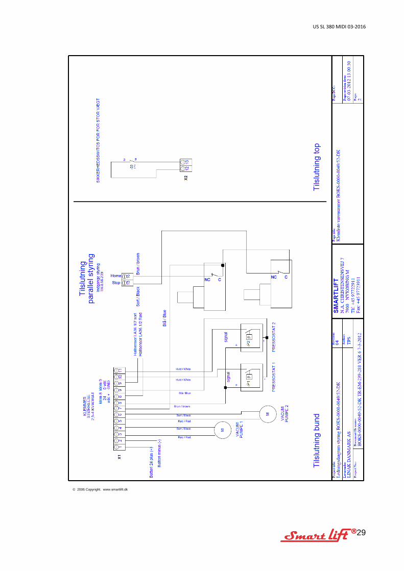
WIRING DIAGRAMS
© 2006 Copyright. www.smartlift.dk
US SL 380 MIDI 03-2016
29
© 2006 Copyright. www.smartlift.dk
US SL 380 MIDI 03-2016
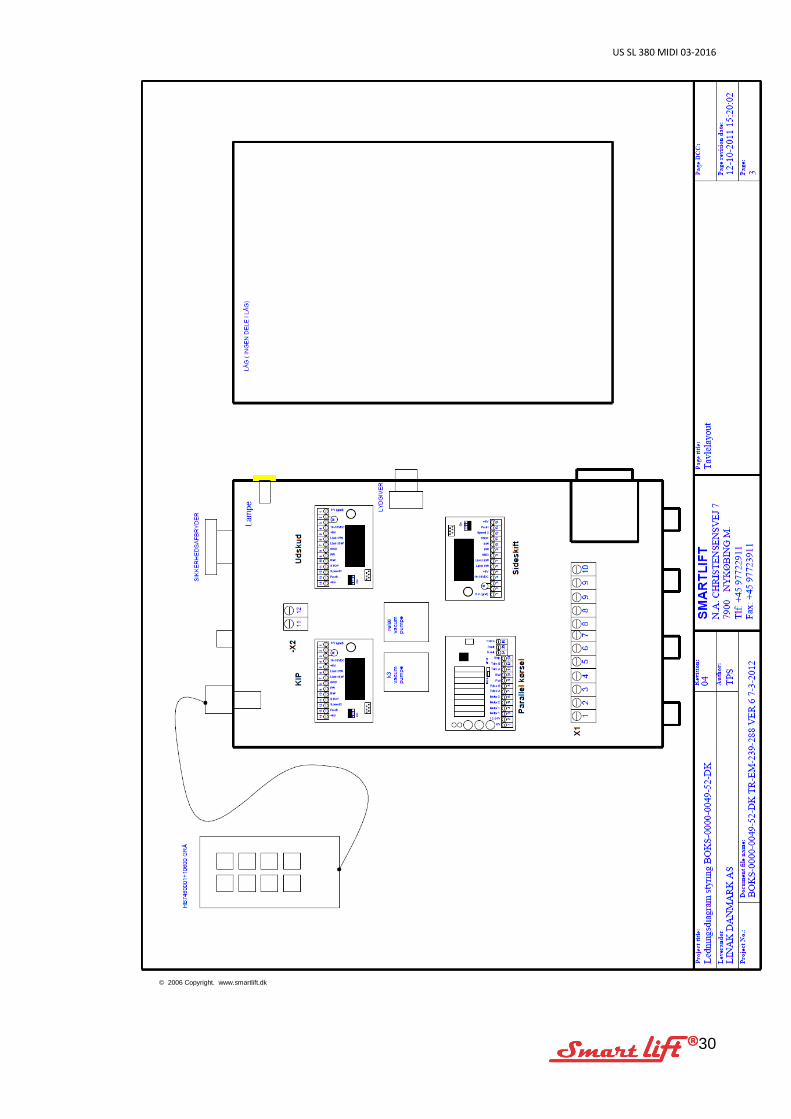
30
© 2006 Copyright. www.smartlift.dk


![Introduction to MIDI & Music Synthesisgutierre/ctlect08.pdf · Introduction to MIDI & Music Synthesis Lecture. ... 7. MIDI Basics [2] {MIDI ... (Standard MIDI Format) {SMF file stores](https://img.dokumen.tips/doc/110x75/5b8412567f8b9aef498b894e/introduction-to-midi-music-gutierrectlect08pdf-introduction-to-midi-music.jpg)