Embed Size (px)
Citation preview

Urban Sketcher:Creating Urban Scenery
Using Multimodal Interfaces
on Large Screen Displays
José Pedro do Sacramento Aleixo Dias
Dissertação para obtenção do Grau de Mestre em
Engenharia Informática e de Computadores
Júri
Presidente: Prof. Ana Maria Severino de Almeida e Paiva
Orientação: Prof. Joaquim Armando Jorge
Vogais: Prof. João Madeiras Pereira
Novembro de 2008

ResumoDesenvolveu-se um sistema para ecrãs de larga escala, fazendo uso de ponteiros laser convencionais como
interface de entrada. Este sistema suporta uso colaborativo. Foi criada uma interface inovadora de modo
a suportar a interacção com tais dispositivos, baseada no conceito de portões e menus circulares não-
intrusivos.
Os utilizadores são capacitados de navegar num mundo virtual utilizando um conjunto de modos de
navegação, nomeadamente: primeira pessoa, modo bússola e modo examinar, assim como um modo de
vôo multimodal, integrando comandos de voz e movimento dos braços. Podem ser criadas e modeladas
formas simples, fazendo uso de um conjunto de ferramentas de modelação que definem um novo modelo
de interacção para a modelação de objectos. Podem ser instanciados edifícios a partir de um conjunto de
estilos de fachada pré-existentes, pelo desenho da sua planta e alçado, dando origem a edifícios únicos.
Estilos adicionais podem ser gerados, recorrendo a um formato XML para definir regras de distribuição de
elementos nas fachadas de edifícios. Os edifícios e restantes objectos podem ser transformados e clonados.
Podem anexar-se anotações a objectos, de modo a suportar cenários de revisão. Um processo alternativo de
criação de edifícios é proposto para tirar proveito do sistema tanto nas primeiras fases como na apresentação
de projectos.
A arquitectura do sistema é descrita, seguida de detalhes de implementação e testes de avaliação. É
demonstrado que os utilizadores conseguiram fazer uso das capacidades do sistema com sucesso. As
conclusões do projecto e trabalho futuro fecham este documento.
Palavras-Chave: traço, edifício, interface multimodal, navegação, ecrã larga escala, BREP
i


AbstractA system was developed for the creation of urban scenarios produced on large screen displays using laser
pointers as input devices and supporting collaborative usage. A novel interface had to be developed to support
interaction with such input devices, based on the concept of gates and circular menus with a non-intrusive
interface.
Users can navigate on a virtual world using a set of comprehensive navigation modes, namely: first
person, bird’s eye view and examine modes, along with a multimodal flight mode controlled by speech com-
mands and arm tracking. Simple shapes can be created and modeled using a minimalistic set of modeling
tools, defining a novel modeling interface. Buildings can be instantiated from a library of facade styles by
drawing the desired blueprint and setting the facade height to generate unique buildings. Additional styles
may be implemented by making use of a developed XML format for defining façade layout rules. Buildings
and other shapes can be transformed and cloned. Objects in the scene can have notes attached to them
to aid in reviewing sessions. An alternative building creation work flow is proposed to take advantage of this
system for early prototypes and showcasing projects.
The system architecture is described thoroughly, followed by implementation details and evaluation tests.
It is shown that users could successfully make use of the offered features based on a stroke-based interface
and set of comprehensive menus. The project conclusions and future work close this document.
Keywords: stroke, building, multimodal, large screen, BREP
iii


AcknowledgementsThe author would like to thank his supervisor, Professor Joaquim Jorge, for his vision, creativity and guidance.
You have given me confidence that everything is possible and assisted me in achieving my goals.
Thanks are due to the rest of the portuguese IMPROVE team members Bruno Araújo, Ricardo Jota and
Luís Bruno. Our numerous brainstorming sessions and subsequent hard work paid off.
The author would also like to thank José António Gonçalves for taking part in the motion tracking navigation
mode and all the test users who volunteered both for the Glasgow and Lisbon tests.
He would like to thank most of all his wife, parents and friends for all the support and understanding given
along this long journey – I couldn’t have made it without you!
v

Table of Contents
Resumo i
Abstract iii
Acknowledgements v
Table of Contents ix
List of Figures xii
List of Tables xiii
List of Acronyms xv
1 Introduction 1
2 Related Work 3
2.1 Existing Solutions . . . . . . . . . . . . . . . . . . . . . . . . . . . . . . . . . . . . . . . . . . 3
2.1.1 Interaction . . . . . . . . . . . . . . . . . . . . . . . . . . . . . . . . . . . . . . . . . . 3
2.1.2 Input Modalities . . . . . . . . . . . . . . . . . . . . . . . . . . . . . . . . . . . . . . . 6
2.1.3 Output Modalities . . . . . . . . . . . . . . . . . . . . . . . . . . . . . . . . . . . . . . 7
2.1.4 Shape Creation . . . . . . . . . . . . . . . . . . . . . . . . . . . . . . . . . . . . . . . 8
2.1.5 Scene Navigation . . . . . . . . . . . . . . . . . . . . . . . . . . . . . . . . . . . . . . 9
2.2 Comparative Analysis of Building Modeling Software . . . . . . . . . . . . . . . . . . . . . . . 11
2.2.1 AutoCAD . . . . . . . . . . . . . . . . . . . . . . . . . . . . . . . . . . . . . . . . . . . 11
2.2.2 ArchiCAD . . . . . . . . . . . . . . . . . . . . . . . . . . . . . . . . . . . . . . . . . . 12
2.2.3 Revit Building . . . . . . . . . . . . . . . . . . . . . . . . . . . . . . . . . . . . . . . . 12
2.2.4 SketchUp . . . . . . . . . . . . . . . . . . . . . . . . . . . . . . . . . . . . . . . . . . 13
2.2.5 Comparison of Tested Solutions . . . . . . . . . . . . . . . . . . . . . . . . . . . . . . 15
3 Design 17
3.1 Proposed Solution . . . . . . . . . . . . . . . . . . . . . . . . . . . . . . . . . . . . . . . . . . 17
3.2 System Architecture . . . . . . . . . . . . . . . . . . . . . . . . . . . . . . . . . . . . . . . . . 17
3.3 Urban Sketcher Input/Output Communication . . . . . . . . . . . . . . . . . . . . . . . . . . . 19
3.4 Stroke-Based Input Interface . . . . . . . . . . . . . . . . . . . . . . . . . . . . . . . . . . . . 20
3.4.1 Strokes . . . . . . . . . . . . . . . . . . . . . . . . . . . . . . . . . . . . . . . . . . . . 20
3.4.2 Gates . . . . . . . . . . . . . . . . . . . . . . . . . . . . . . . . . . . . . . . . . . . . 20
3.4.3 Menus . . . . . . . . . . . . . . . . . . . . . . . . . . . . . . . . . . . . . . . . . . . . 21
3.4.4 Stroke Gestures . . . . . . . . . . . . . . . . . . . . . . . . . . . . . . . . . . . . . . . 22
3.4.5 Main Menu vs Contextual Menu . . . . . . . . . . . . . . . . . . . . . . . . . . . . . . 22
3.5 Multimodal Input Interface . . . . . . . . . . . . . . . . . . . . . . . . . . . . . . . . . . . . . . 22
3.6 Content Creation Concepts . . . . . . . . . . . . . . . . . . . . . . . . . . . . . . . . . . . . . 23
vii

3.6.1 Apply-to-Scene Creation . . . . . . . . . . . . . . . . . . . . . . . . . . . . . . . . . . 23
3.6.2 Instancing a Building . . . . . . . . . . . . . . . . . . . . . . . . . . . . . . . . . . . . 24
4 Implementation 25
4.1 Navigation . . . . . . . . . . . . . . . . . . . . . . . . . . . . . . . . . . . . . . . . . . . . . . 25
4.1.1 First Person Mode . . . . . . . . . . . . . . . . . . . . . . . . . . . . . . . . . . . . . . 26
4.1.2 Compass Mode . . . . . . . . . . . . . . . . . . . . . . . . . . . . . . . . . . . . . . . 26
4.1.3 Examine Mode . . . . . . . . . . . . . . . . . . . . . . . . . . . . . . . . . . . . . . . . 27
4.1.4 Multimodal Flight Mode . . . . . . . . . . . . . . . . . . . . . . . . . . . . . . . . . . . 27
4.1.5 Other possible navigational modes . . . . . . . . . . . . . . . . . . . . . . . . . . . . . 28
4.2 Creating Content . . . . . . . . . . . . . . . . . . . . . . . . . . . . . . . . . . . . . . . . . . 29
4.2.1 Shape Internal Structure . . . . . . . . . . . . . . . . . . . . . . . . . . . . . . . . . . 29
4.2.2 Shape Instancing . . . . . . . . . . . . . . . . . . . . . . . . . . . . . . . . . . . . . . 30
4.2.3 Shape Templates . . . . . . . . . . . . . . . . . . . . . . . . . . . . . . . . . . . . . . 30
4.2.4 Building Style . . . . . . . . . . . . . . . . . . . . . . . . . . . . . . . . . . . . . . . . 30
4.2.5 Instancing Buildings . . . . . . . . . . . . . . . . . . . . . . . . . . . . . . . . . . . . . 31
4.3 Editing Content . . . . . . . . . . . . . . . . . . . . . . . . . . . . . . . . . . . . . . . . . . . 32
4.3.1 Face and Edge Selection . . . . . . . . . . . . . . . . . . . . . . . . . . . . . . . . . . 32
4.3.2 Determining and Selecting Directions . . . . . . . . . . . . . . . . . . . . . . . . . . . 32
4.3.3 Shape Operations . . . . . . . . . . . . . . . . . . . . . . . . . . . . . . . . . . . . . . 33
4.4 Reviewing . . . . . . . . . . . . . . . . . . . . . . . . . . . . . . . . . . . . . . . . . . . . . . 35
4.5 Proposed Work Flow . . . . . . . . . . . . . . . . . . . . . . . . . . . . . . . . . . . . . . . . 35
4.5.1 Scenario Creation . . . . . . . . . . . . . . . . . . . . . . . . . . . . . . . . . . . . . . 35
4.5.2 Building Style Creation . . . . . . . . . . . . . . . . . . . . . . . . . . . . . . . . . . . 36
5 Evaluation 37
5.1 Intermediate Tests . . . . . . . . . . . . . . . . . . . . . . . . . . . . . . . . . . . . . . . . . . 37
5.1.1 Test Environments . . . . . . . . . . . . . . . . . . . . . . . . . . . . . . . . . . . . . . 37
5.1.2 Results . . . . . . . . . . . . . . . . . . . . . . . . . . . . . . . . . . . . . . . . . . . . 37
5.2 Final Tests . . . . . . . . . . . . . . . . . . . . . . . . . . . . . . . . . . . . . . . . . . . . . . 38
5.2.1 Conditions . . . . . . . . . . . . . . . . . . . . . . . . . . . . . . . . . . . . . . . . . . 38
5.2.2 Test Environment . . . . . . . . . . . . . . . . . . . . . . . . . . . . . . . . . . . . . . 39
5.2.3 Results . . . . . . . . . . . . . . . . . . . . . . . . . . . . . . . . . . . . . . . . . . . . 39
6 Conclusion 45
6.1 Results . . . . . . . . . . . . . . . . . . . . . . . . . . . . . . . . . . . . . . . . . . . . . . . . 45
6.2 Main Contributions . . . . . . . . . . . . . . . . . . . . . . . . . . . . . . . . . . . . . . . . . 45
6.3 Conclusions and Future Work . . . . . . . . . . . . . . . . . . . . . . . . . . . . . . . . . . . 46
Bibliography 49
viii
I Appendices
A Appendix: Building Style Example 55
Residential Style . . . . . . . . . . . . . . . . . . . . . . . . . . . . . . . . . . . . . . . . . . . . . 56
B Appendix: Final Tests 57
Final Test Forms . . . . . . . . . . . . . . . . . . . . . . . . . . . . . . . . . . . . . . . . . . . . . 58
Final Test Tasks . . . . . . . . . . . . . . . . . . . . . . . . . . . . . . . . . . . . . . . . . . . . . . 62
C Appendix: Related Papers 65
GeoSculpt Short Paper . . . . . . . . . . . . . . . . . . . . . . . . . . . . . . . . . . . . . . . . . . 66
Multimodal Interaction Short Paper . . . . . . . . . . . . . . . . . . . . . . . . . . . . . . . . . . . . 68
15th EPCG ImmiView Paper . . . . . . . . . . . . . . . . . . . . . . . . . . . . . . . . . . . . . . . 70
ix


List of Figures
2.1 The augmented view seen from the HMD; a user of the ARVIKA system . . . . . . . . . . . . 3
2.2 Two users collaborating on a Google Earth tabletop session . . . . . . . . . . . . . . . . . . . 4
2.3 The suggested speech and gesture interface for Google Earth . . . . . . . . . . . . . . . . . . 5
2.4 Digital Whiteboard: Pick-and-drop interaction; Working areas for each participant’s palmtop. . . 5
2.5 HMD, Wall, CAVE . . . . . . . . . . . . . . . . . . . . . . . . . . . . . . . . . . . . . . . . . . 7
2.6 A view of a drawing done in 40 minutes with SESAME . . . . . . . . . . . . . . . . . . . . . . 8
2.7 Drawing done with SmartPaper . . . . . . . . . . . . . . . . . . . . . . . . . . . . . . . . . . . 9
2.8 The process of modeling a lamp in SmartPaper . . . . . . . . . . . . . . . . . . . . . . . . . . 9
2.9 SPB Cam: Maintenance strategy for keeping high orientation values; Adjustment strategy for
ensuring of feasible view specifications. . . . . . . . . . . . . . . . . . . . . . . . . . . . . . . 10
2.10 One long path and one short one . . . . . . . . . . . . . . . . . . . . . . . . . . . . . . . . . . 11
2.11 AutoCAD: A typical layout of a floor plan. . . . . . . . . . . . . . . . . . . . . . . . . . . . . . 12
2.12 ArchiCAD: Notice basic selection and template properties editing in the 3D view. . . . . . . . . 13
2.13 Revit Building: Solid shapes can be combined with boolean operations and converted into
buildings. . . . . . . . . . . . . . . . . . . . . . . . . . . . . . . . . . . . . . . . . . . . . . . . 13
2.14 SketchUp: Basic shape extrusions. Notice the shadows in the viewport. . . . . . . . . . . . . . 14
3.1 Urban Sketcher interaction scenario . . . . . . . . . . . . . . . . . . . . . . . . . . . . . . . . 17
3.2 Urban Sketcher Architecture Diagram . . . . . . . . . . . . . . . . . . . . . . . . . . . . . . . 18
3.3 Urban Sketcher input/output Diagram . . . . . . . . . . . . . . . . . . . . . . . . . . . . . . . 19
3.4 Gate activation . . . . . . . . . . . . . . . . . . . . . . . . . . . . . . . . . . . . . . . . . . . . 21
3.5 Menu and its areas . . . . . . . . . . . . . . . . . . . . . . . . . . . . . . . . . . . . . . . . . 21
3.6 Main menu stroke . . . . . . . . . . . . . . . . . . . . . . . . . . . . . . . . . . . . . . . . . . 22
3.7 Edge and Face selection . . . . . . . . . . . . . . . . . . . . . . . . . . . . . . . . . . . . . . 22
3.8 A user with reflective markers and wireless headset . . . . . . . . . . . . . . . . . . . . . . . 23
3.9 Apply-to-scene procedure - creating a shape . . . . . . . . . . . . . . . . . . . . . . . . . . . 24
3.10 Building creation procedure . . . . . . . . . . . . . . . . . . . . . . . . . . . . . . . . . . . . . 24
4.1 Main menu and all three navigation menu modes . . . . . . . . . . . . . . . . . . . . . . . . . 25
4.2 Concept supporting examine mode . . . . . . . . . . . . . . . . . . . . . . . . . . . . . . . . 27
4.3 Flight mode: controlling speed and direction . . . . . . . . . . . . . . . . . . . . . . . . . . . . 28
4.4 Shape menu . . . . . . . . . . . . . . . . . . . . . . . . . . . . . . . . . . . . . . . . . . . . . 29
4.5 Resulting building of residential style. Several components are highlighted for comprehension. 31
4.6 Edge and Face selection and their contextual menus . . . . . . . . . . . . . . . . . . . . . . . 32
4.7 Face directions . . . . . . . . . . . . . . . . . . . . . . . . . . . . . . . . . . . . . . . . . . . 33
4.8 Shape operation example applications . . . . . . . . . . . . . . . . . . . . . . . . . . . . . . . 34
4.9 Creating a note and the result attached to a door . . . . . . . . . . . . . . . . . . . . . . . . . 35
5.1 A user performing multimodal flight during the Lighthouse test . . . . . . . . . . . . . . . . . . 38
xi

5.2 Box and whiskers charts comparing task completion times on both systems . . . . . . . . . . 40
5.3 Box and whiskers charts illustrating close-ended answers . . . . . . . . . . . . . . . . . . . . 41
5.4 Pie charts illustrating the clustered open-ended answers . . . . . . . . . . . . . . . . . . . . . 42
xii

List of Tables
2.1 Table comparing four different building modeling packages . . . . . . . . . . . . . . . . . . . . 15
5.1 Task completion times on Urban Sketcher and Google SketchUp . . . . . . . . . . . . . . . . 40
5.2 Preliminary and Final Questionnaire close-ended questions and results . . . . . . . . . . . . . 41
5.3 Final Questionnaire open-ended questions and clustered answers . . . . . . . . . . . . . . . . 42
xiii

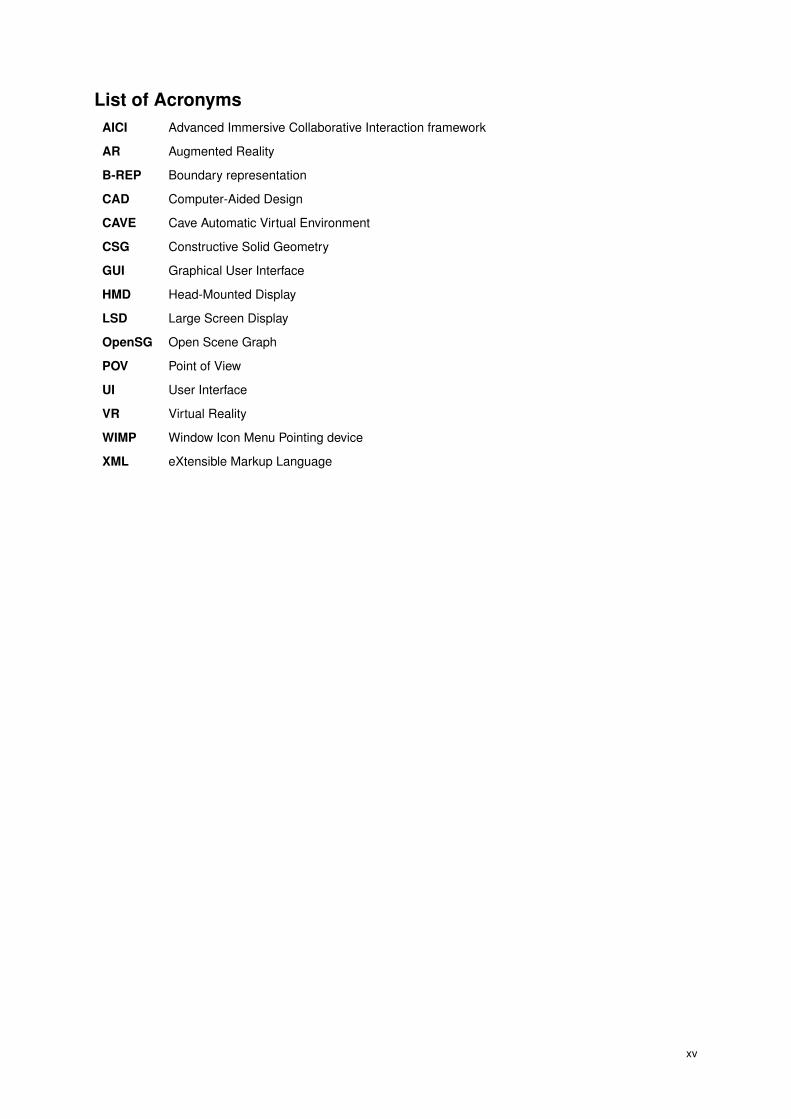
List of AcronymsAICI Advanced Immersive Collaborative Interaction framework
AR Augmented Reality
B-REP Boundary representation
CAD Computer-Aided Design
CAVE Cave Automatic Virtual Environment
CSG Constructive Solid Geometry
GUI Graphical User Interface
HMD Head-Mounted Display
LSD Large Screen Display
OpenSG Open Scene Graph
POV Point of View
UI User Interface
VR Virtual Reality
WIMP Window Icon Menu Pointing device
XML eXtensible Markup Language
xv


1 Introduction
With the advent of advanced visualization hardware it is now possible to interact with complex representations
of urban scenarios. There is a myriad of systems supporting the modeling of three-dimensional content but
they tend to be overly complex and make use of concepts focused on mouse and keyboard interaction. There
is a demand for systems capable of offering 3D scenes rendering and supporting multi-user interaction on
large screens on fields so disparate as architecture and the entertainment industry.
This project aims at offering a simple to learn interface for collaborative interaction on large screen dis-
plays. It supports both laser pointers and a multimodal arms motion tracking plus speech recognition modes:
the former for controlling actions, navigation and modeling; the latter for an alternative, hands-free flying
navigation mode.
The application of such interface is a system for fast creation of city landscapes by means of instancing
template-based building styles the minimal set of strokes, along with a modeling tool kit capable of editing 3D
shapes by manipulating its faces and edges through their most common directions.
The state of the art in this domain was sought out. No project mapping the objectives of this project has
been developed though some, due to their dimension or common ground, were subject of analysis. Work from
other authors was reviewed when it addressed relevant problems, subject of usage on the project. The most
well known software bundles were compared to analyze possible solutions and avoid common mistakes.
Developing an application for such purposes requires dealing with several aspects – the large scale ren-
dering of the scenario, giving people means to interact with the screen, allowing people to interact at the
same time and offering a simple interface adapted to the running environment. Several navigation modes
were developed to enhance the user experience, most notably a multimodal flight mode controlled by the user
arms motion and triggered by voice commands. A set of rules was designed so building templates could be
created and instanced easily on the scene. A set of modeling operations was defined and implemented so a
novice user could perform simple yet effective modeling operations to enrich the scene with details.
This system’s interface was set for large screen displays and laser pointers chosen as the main source of
user input due to it being both portable and light. The usage of laser pointers issues the problem that a laser
pointer can not be tracked while the light is not turned on. Clicking behaviors are hard to detect and users can
not be precise while unable to view the laser pointer’s projection on the screen. An alternate interface urged
to solve this issue – instead of the commonly used buttons and drop-down menus, crossable areas and ring
shaped menus were introduced. These menus can be invoked where needed by issuing a closed triangle
gesture, to better explore the available space on the screen.
The design and development of this system was routinely tested with users for detailing the layout of
menus, readability of the featured action icons and validate innovative features, namely the flight mode,
template-based instancing of buildings and shape modeling tools.
At the final usability tests, for every mappable feature, tasks were performed on both Urban Sketcher and
other system – Google SketchUp1. Even though GSU relies on desktop concepts and input/output devices,
users were able to perform the tasks successfully and took less than twice the time performing them using
such devices and interface. Users easily learned the system’s features and their menus, being able to easily
1Google SketchUp – http://www.sketchup.com
1
create 3D content such as buildings (template-based) and custom objects (using a tool set of simple modeling
tools).
This project takes advantage of large screen displays, made possible by the devised interface based on
area activation and ring menus, with users applying discrete strokes using laser pointers. The navigation and
shape creation functionalities focused on simplicity, offering a set of tools and the capability to extend the
software with additional scenarios and facade styles. A novel set of modeling tools and interaction gestures
was put to work, with emphasis on a multimodal flight navigation mode.
Following is the related work chapter where a set of solutions devised by other authors are discussed. A
comparative analysis on commercial software bundles is performed to emphasize their advantages and avoid
their flaws. The design chapter is next, describing the broad view of the Urban Sketcher project, its architec-
ture, modules and purpose. The concepts used throughout this document are defined here. Subsequently
one can find the implementation chapter, where the various navigation modes are defined and justified, as
are the content creation, editing and review features which make part of the system. An alternative cityscape
drafting workflow is then suggested taking advantage of the system developed. The process of evaluation is
described, presented and discussed on the evaluation chapter. The document ends stating the results which
have been reached, the main contributions this project introduces and ways it can be enhanced in the future.
2

2 Related Work
This section is the result of researching existing academic and commercial software systems and publica-
tions. Since no prior systems addressing this set of requirements could be determined, related work was
sought to cover sub-problems related to the design and implementation of such a system. An analysis is
then conducted regarding input and output modalities capable of enabling such scenarios, along with a set of
shape creation and scene navigation techniques. A comparative analysis of commercially available building
modeling software is then conducted.
2.1 Existing Solutions
The set of available motion tracking techniques for gathering user input is discussed. The most common
setups for rendering virtual reality scenes are compared. Two shape creation projects are analyzed and three
scene navigation concepts visited.
2.1.1 Interaction
Three systems will be discussed in this area, each one withstanding common goals with the idealized solution.
2.1.1.1 ARVIKA, 2003
ARVIKA [Fri02] is a project with sponsoring from the German Federal Ministry of Education and Research
that was implemented between 1999 and 2003. It focused on the development of Augmented Reality (AR)
technologies to aid in performing industrial tasks. The consortium involved several industrial partners such as
Volkswagen, BMW, Siemens and Airbus.
Figure 2.1: The augmented view seen from the HMD; a user of the ARVIKA system
An expert in the industrial area would carry a head-mounted display (HMD) with a camera mounted on
it. The real-time captured video was then interpreted and markers extracted from the image. The camera’s
positioning and orientation were estimated and the HMD view was enriched with virtual objects (see figure
2.1, left). The framework was distributed in the form of an ActiveX plug-in for the Internet Explorer browser
named ARBrowser.
Weidenhausen et al. [JWS03] consider the deployment of the project as an ActiveX component to be an
advantage since it is based on a widespread program (Internet Explorer) and allowed developers to create
3

task scenarios with familiar technologies such as JavaScript and HTML. Although the world’s largest research
project in the area, ARVIKA focused too much on the technical problems regarding AR and little effort was
spent on the creation of a suitable user interface. The authors agree on a point: “most people judge the
usefulness of a technology mainly by its user interface”. Therefore this particular topic became work for future
project iterations. ARVIKA was meant to support many industrial scenarios – development, production and
services for several industrial partners on different domains. Creating a scenario was a time consuming task
– taking several days, according to Weidenhausen et al. – and required extensive knowledge in 3D modeling
tools and VRML. No authoring capabilities were given to end-users. This problem was identified as paramount
and an authoring tool was scheduled for future development, supporting generic task creation with parameters
controlled by the users.
2.1.1.2 Speech and Gestures on a Multi-User Tabletop, 2006
Tse et al. [TSGF06] developed a multimodal interface on top of Google Earth1 to be run on a multi-touch
table. The system allows multi-user collaboration with touch and voice commands.
The main problems found in adapting Google Earth reside in the fact that it was thought out as a single user
program, where only one action could be done at a time. In this scenario several users could be disposed
around the table with different orientations, so text readability problems arose. Additionally, user interface
components such as the compass were placed at fixed points on the screen, an approach that does not
favor multi-user scenarios. At 1024 x 768 resolution it was estimated that 42% of the screen was originally
consumed by GUI elements. Since all users shared the surface, turn-taking had to be agreed by the users,
not being enforced by the system (see figure 2.2). Most Google Earth interactive actions were mapped into
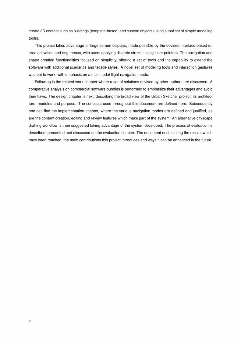
gestures, leaving the most abstract actions for voice commands activation (see figure 2.3).
Figure 2.2: Two users collaborating on a Google Earth tabletop session
This project shows the difficulties in adapting a production software thought out for single user WIMP2
interfaces for the support of collaborative scenarios. A multimodal interface was built over the existing one,
mapping most of its commands. The set of obtained commands is a good example of how navigation can
be performed on 3D scenery using a multimodal interface. Google Earth is a good example of a navigation
1Google Earth – http://earth.google.com2Window Icon Menu Pointing device
4
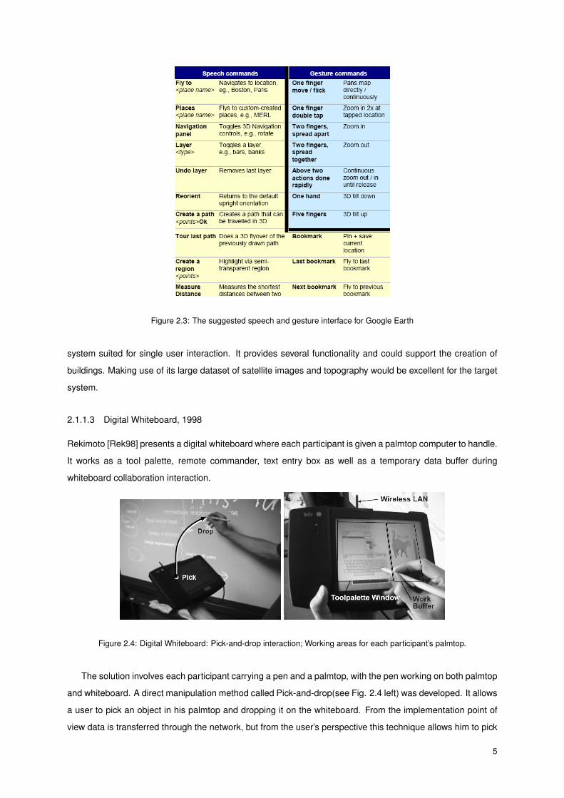
Figure 2.3: The suggested speech and gesture interface for Google Earth
system suited for single user interaction. It provides several functionality and could support the creation of
buildings. Making use of its large dataset of satellite images and topography would be excellent for the target
system.
2.1.1.3 Digital Whiteboard, 1998
Rekimoto [Rek98] presents a digital whiteboard where each participant is given a palmtop computer to handle.
It works as a tool palette, remote commander, text entry box as well as a temporary data buffer during
whiteboard collaboration interaction.
Figure 2.4: Digital Whiteboard: Pick-and-drop interaction; Working areas for each participant’s palmtop.
The solution involves each participant carrying a pen and a palmtop, with the pen working on both palmtop
and whiteboard. A direct manipulation method called Pick-and-drop(see Fig. 2.4 left) was developed. It allows
a user to pick an object in his palmtop and dropping it on the whiteboard. From the implementation point of
view data is transferred through the network, but from the user’s perspective this technique allows him to pick
5

up digital data as if it were a physical object. Text entry is performed on the palmtop and each user can choose
the method he favors (i.e.: handwritten recognition, soft keyboard, etc) for entering text. No menus or tool
palettes exist on the whiteboard – they’re available on each user’s palmtop. The main window is a multi page
tool panel. A user can flip to several tool palette pages, with the remaining area available as a temporary work
buffer. Users can store data elements in this window and paste them to the whiteboard using Pick-and-Drop
operations. (see Fig. 2.4 right).
Rekimoto concludes that by putting many functions on palmtops, users tend to concentrate too much on
their own palmtop devices, degrading mutual awareness among the participants. Pick-and-Drop often worked
better than drag-and-drop, particularly when user had to move objects for a long distance. Drag-and-drop
forces a user to keep the pen tip in contact with the board during the entire operation, a restriction not suitable
for large display surfaces.
The solution where each user carries a palmtop for the creation of content such as note taking is suitable
for an architectural design and review scenario. It grants the user the power to draw, type text or compose
graphics independently from one another and then replicating the information on the whiteboard. On the
other hand there’s the danger of users focusing too much on their palmtop and losing awareness of what’s
happening at the whiteboard. As result of this, a smaller interface device without all this functionality might be
as suitable for interacting with a large screen, provided that these functionalities are offered by the interface.
2.1.2 Input Modalities
2.1.2.1 Motion Tracking Systems
Welch and Foxlin [WF02] conducted a survey on motion tracking systems, comparing each solution in terms
of cost, precision and capacity to solve the tracking problem. The main group of purposes for motion tracking
applications was identified: view control, navigation, object selection or manipulation, instrument tracking
and avatar animation. There are motion tracking systems available based on measurements of mechanical,
inertial, acoustic, magnetic, optical and radio frequency sensors, each approach bearing its advantages and
limitations. The most robust solution lies in combining two technologies, such as a hybrid between inertial and
acoustic sensors – the former providing six degrees of freedom data and the latter reading precise positioning
for each artifact.
One can envision the proposed solution to use motion tracking to allow users to change their point of
view in the program, navigate the scene, select and manipulate objects, a subset of functionality identified by
Welch and Foxlin.
2.1.2.2 Augmented Reality versus Immersive Virtual Reality
According to Azuma [Azu04] Augmented Reality should be used when the collaboration task is co-located,
when there is tangible object interaction and enhanced interaction in the real world. Immersive Virtual Reality
is preferred on scenarios with shared views and remote collaboration.
Sharing views and doing collaboration are two expected features of this system so Virtual Reality is the
choice to make. No Augmented Reality feature is found in this project.
6
2.1.3 Output Modalities
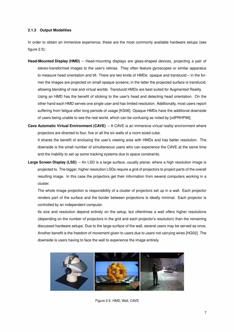
In order to obtain an immersive experience, these are the most commonly available hardware setups (see
figure 2.5):
Head-Mounted Display (HMD) – Head-mounting displays are glass-shaped devices, projecting a pair of
stereo-transformed images to the user’s retinas. They often feature gyroscopes or similar apparatus
to measure head orientation and tilt. There are two kinds of HMDs: opaque and translucid – in the for-
mer the images are projected on small opaque screens; in the latter the projected surface is translucid,
allowing blending of real and virtual worlds. Translucid HMDs are best suited for Augmented Reality.
Using an HMD has the benefit of sticking to the user’s head and detecting head orientation. On the
other hand each HMD serves one single user and has limited resolution. Additionally, most users report
suffering from fatigue after long periods of usage [KS06]. Opaque HMDs have the additional downside
of users being unable to see the real world, which can be confusing as noted by [vdPRHP99].
Cave Automatic Virtual Environment (CAVE) – A CAVE is an immersive virtual reality environment where
projectors are directed to four, five or all the six walls of a room-sized cube.
It shares the benefit of enclosing the user’s viewing area with HMDs and has better resolution. The
downside is the small number of simultaneous users who can experience the CAVE at the same time
and the inability to set up some tracking systems due to space constraints.
Large Screen Display (LSD) – An LSD is a large surface, usually planar, where a high resolution image is
projected to. The bigger, higher resolution LSDs require a grid of projectors to project parts of the overall
resulting image. In this case the projectors get their information from several computers working in a
cluster.
The whole image projection is responsibility of a cluster of projectors set up in a wall. Each projector
renders part of the surface and the border between projections is ideally minimal. Each projector is
controlled by an independent computer.
Its size and resolution depend entirely on the setup, but oftentimes a wall offers higher resolutions
(depending on the number of projectors in the grid and each projector’s resolution) than the remaining
discussed hardware setups. Due to the large surface of the wall, several users may be served as once.
Another benefit is the freedom of movement given to users due to users not carrying wires [HG02]. The
downside is users having to face the wall to experience the image entirely.
Figure 2.5: HMD, Wall, CAVE
7

Any of these setups is suitable for single user interaction. In case of a reviewing session at which at least
two participants are required, CAVEs or LSDs are better suited, since they both offer a single solution for a
small group of people.
Using a CAVEs or LSDs presents other challenges: the computers responsible for the generation of
the projectors’ images must be synchronized, the projectors color parameters calibrated and the viewport
must be well cropped. There are several systems capable of delivering high performance 3D graphics and
offering the features mentioned above. Based on scene graphs there are two well established solutions:
OpenSceneGraph3 and OpenSG4. The framework on top of which our system was build runs on OpenSG.
2.1.4 Shape Creation
In this section two solutions suitable for conceptual sketching of 3D forms are analyzed.
2.1.4.1 SESAME, 2006
Oh, Stuerzlinger and Danahy [OSD06] developed SESAME (Sketch, Extrude, Sculpt, and Manipulate Easily).
This system focus on providing an interface as powerful and easy as 2D sketching on paper. The authors
defend that a 3D model is more easily understood among users than a regular conceptual design. It is
optimized for modification and allows the creation and editing of volumetric geometry by extruding 2D contours
or sculpting 3D volumes. It features a simple toolbar interface, allowing the creation of lines, arcs and free-form
curves with constraints - see figure 2.6. SESAME also supports automatic grouping of objects, i.e., objects
related between themselves (ex: cup on top of table) affect each other. User tests conducted comparing
SESAME with the modeling package Autodesk 3D Studio Max have shown that even experienced 3DSM
users found the drawings done with SESAME to be more creative and satisfying.
Figure 2.6: A view of a drawing done in 40 minutes with SESAME
This is a promising direction for an urban sketching software to go. The tests against 3D Studio Max were
a bit skewed – the test should have been conducted against a system of similar approach, such as Google
Sketchup. The offered interface in SESAME is plain and improper for large screens or collaboration.
3OpenSceneGraph – http://www.openscenegraph.org4OpenSG – http://opensg.vrsource.org
8

2.1.4.2 SmartPaper, 2004
Shesh and Chen [SC04] developed SmartPaper, a system designed to support 2D sketching featuring overs-
ketching capabilities, sketch on 3D, 3D transforms and CSG operations. It employs a non-photorealistic
rendering technique to convey the drawing a sketchy look – see figure 2.7.
Figure 2.7: Drawing done with SmartPaper
Figure 2.8: The process of modeling a lamp in SmartPaper
SmartPaper requires users to draw all object’s edges, not only the visible ones (figure 2.8). In the case
of extruded objects this is not problematic, since the original face would always have to be drawn anyway.
Another problem is with users having trouble creating perspective drawings. The resulting geometry appears
to be irregular but since the goal is to do conceptual drawings this is not an issue.
2.1.5 Scene Navigation
Following is a list of scene navigation solutions. Each one can contribute to a more easy and powerful interface
for navigation tasks.
2.1.5.1 Smart and Physically Based Camera, 2006
In order to ensure users not “getting lost” in the virtual space, Buchholz, Bohnet and Döllner [BBD05] propose
a smart and physically based camera. Smart in the sense that it is aware of confusing and disorienting viewing
situations, providing means to circumvent them. Physically based because it is supported by a physics model
of 3D motion to ensure steady, continuous user movements.
Experience shows that people frequently lose track of their location when moving on a three-dimensional
world. To solve this problem, the camera must identify situations when to intervene. For that reason a metric,
called orientation value, was created. Each view is classified by counting its pixels, granting different values:
landmarks get the highest values; terrain gets mid-range values and the sky gets lower values (see Fig. 2.9,
9

right). A threshold can then be established and views below the threshold are classified “disoriented”. When
such an event takes place, smart navigation techniques restrict camera control. The constraints posed to
user control must be as comprehensible as possible. Camera movement should also be time-coherent and
physically sound.
The maintenance strategy solves critical situations such as (see Fig.2.9, left):
a) The user rotates the flight direction and causes the camera to look too far beyond the terrain border. The
rotation is accepted but outweighed by a slight rear movement away from the border.
b) The user is flying forward beyond the terrain border. The maintenance strategy temporarily tilts down the
view direction until a maximum angle is reached.
c) If no more tilting is possible, the strategy rotates the flight direction parallel to the terrain to fly along the
terrain border.
Figure 2.9: SPB Cam: Maintenance strategy for keeping high orientation values; Adjustment strategy for ensuring of
feasible view specifications.
A camera system such as this can be useful aiding non-experienced users such as clients in navigation
tasks since it maximizes the presence of landmarks in the user’s view. The physically-based engine would
grant additional realism to the navigation experience, providing collision detection, inertia and a spring behav-
ior that would soften camera trajectories.
2.1.5.2 Speed-dependent Automatic Zooming, 2000
Igarashi and Hinckley [IH00] propose a simple idea for scrolling through large areas of information. The speed
at which the scrolling occurs changes the zooming of the seen area. This makes sense since the faster the
area is scrolling, the longer ahead the user needs to see.
This could be easily applied to bird’s-eye-view maps of large areas. The scrolling of the map would trigger
different zooming factors depending on the scrolling speed, improving the navigation and exploration of the
map.
10

2.1.5.3 Path Drawing for 3D Walkthrough, 1998
Igarashi et al. [IKMT98] start by identifying the two main types of walk-through techniques: driving, where the
user continuously changes camera position with move and rotation buttons and flying, where the user picks
the desired destination with a pointing device and a trajectory is calculated and animated from the starting
position to the picked one. Each has its disadvantages: driving requires the user to control the trajectory at
all times; flying lacks expressive power since the user can not control the path neither the final orientation.
The proposed solution is an extension of the flying technique: the user draws the desired path he wants
to take on the screen. It gets projected onto the walking surfaces and the generated path is animated. During
the animation the user faces the tangential direction related to the path. This brings the additional advantage
of the user being able to define where he will be facing at the end of the animation. This technique can be
used is two different ways. The user can draw a long stroke specifying the path at once or he can draw
successions of small strokes (see Fig.2.10).
As limitations the authors state the path expressiveness being limited to the walking surface planes and
the need for the user’s avatar to be present on the view if one wants to draw the path from the user’s feet.
Figure 2.10: One long path and one short one
This navigation mode could be handy in the review scenario. Even so this might be hard to apply to the
project due to LSD interface limitations.
2.2 Comparative Analysis of Building Modeling Software
In this section, popular commercial solutions for modeling buildings are analyzed, highlighting each solution’s
strengths and weaknesses. A table ranking each solution in several relevant aspects is then presented and
discussed, marking the distinguishing features found on the analyzed software.
2.2.1 AutoCAD
Autodesk AutoCAD5 is the de facto standard software for architecture designs. It has a steep learning curve
(Fig.2.11) but is nevertheless learned all over the world. One of its formats, DXF, is widely supported by 3D
modeling software. AutoCAD features a powerful language, AutoLisp, which allows advanced users to create
5Autodesk AutoCAD – http://www.autocad.com
11

scripts for automating any aspect available in the interface. This program favors 2D drawing and modeling
over real 3D concepts, but a skillful operator can create every shape necessary to an architectural scenario.
Internally AutoCAD doesn’t support interactive previewing of the created designs. It renders using the powerful
Mental Ray engine. Animations can be made using camera paths.
There are hundreds of commercial plug-ins extending the capabilities of AutoCAD in a multitude of fea-
tures.
Figure 2.11: AutoCAD: A typical layout of a floor plan.
2.2.2 ArchiCAD
GraphiCad’s ArchiCAD6 aims at conquering the new generation of architects who haven’t been exposed to
AutoCAD. It offers pre-made views and document templates for every architectural driven need. It is by
definition a 3D CAD program and it is praised by architects for its easy 3D manipulation capabilities (Fig.2.12).
The program features templates for common architectural elements. ArchiCAD has navigation capabilities
too, allowing first person perspective navigation of the model. Its workflow is thought out to make it easy for
an architect to do the most common tasks, making it a friendlier alternative when compared to AutoCAD. It
lacks the expressive power to do about 10% uncommon tasks though. There’s a Software Development Kit
for ArchiCAD plug-in creation.
2.2.3 Revit Building
Revit Building7 is another Autodesk product. Unlike AutoCAD, which spans its use to other areas such as
mechanical engineering, Revit Building was explicitly thought out for architectural design.
It works completely in 3D and has native templates for doors, windows, roofs, etc. Common constraints
are detected. Thick walls can be drawn as lines and solids can be cut as floors (compare the top-left and
bottom right views in Fig.2.13).
6GraphiCad ArchiCAD – http://www.graphisoft.com/products/archicad7Autodesk Revit Building – http://www.autodesk.com/revit
12

Figure 2.12: ArchiCAD: Notice basic selection and template properties editing in the 3D view.
Revit Building features powerful templates for complex tasks such as roof design. It has a simple raytracing
and radiosity engine. Cameras can be placed for view rendering but not animation.
Being a system for the professional segment, it has a smoother learning curve than AutoCAD and provides
tools that allow successful modeling of complex buildings, even for enthusiasts, a quality not held by AutoCAD.
Figure 2.13: Revit Building: Solid shapes can be combined with boolean operations and converted into buildings.
2.2.4 SketchUp
Google SketchUp8 is a friendly program for the novice 3D modeler. It features a simple toolbar interface with
one viewport and most of its tools are basic. One is still able to achieve acceptable results with it. Its learning
curve is good. Its engine is based on drawing lines on top of lines, already created surfaces or a construction
plane. It detects the most common geometry restrictions (such as midpoint and perpendicularity). It features
an online repository of models, allowing importing of objects such as furniture, trees, props or well known
8Google SketchUp – http://www.sketchup.com
13
buildings by browsing and selection. Strange results occur when handling awkward angles or several lines
are the vicinity of the mouse. Curve manipulation and generation of surfaces is nonexistent. SketchUp allows
plug-in design using the Ruby language.
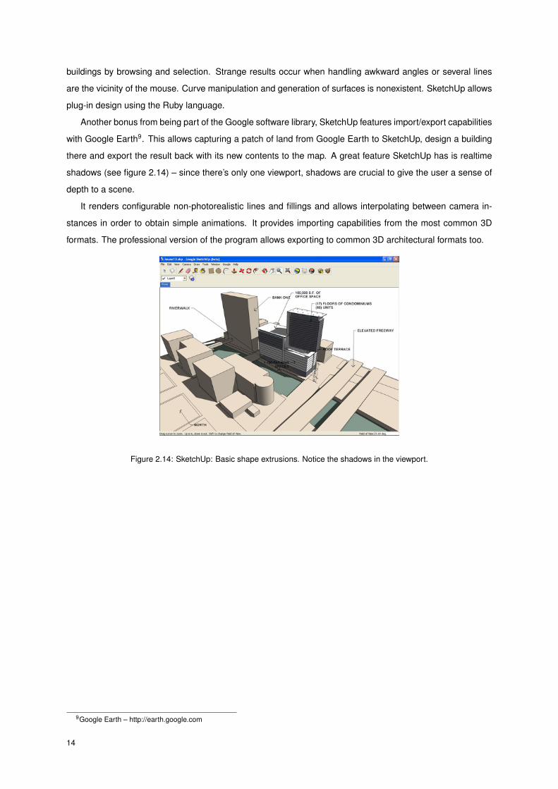
Another bonus from being part of the Google software library, SketchUp features import/export capabilities
with Google Earth9. This allows capturing a patch of land from Google Earth to SketchUp, design a building
there and export the result back with its new contents to the map. A great feature SketchUp has is realtime
shadows (see figure 2.14) – since there’s only one viewport, shadows are crucial to give the user a sense of
depth to a scene.
It renders configurable non-photorealistic lines and fillings and allows interpolating between camera in-
stances in order to obtain simple animations. It provides importing capabilities from the most common 3D
formats. The professional version of the program allows exporting to common 3D architectural formats too.
Figure 2.14: SketchUp: Basic shape extrusions. Notice the shadows in the viewport.
9Google Earth – http://earth.google.com
14

2.2.5 Comparison of Tested Solutions
Features
SolutionsAutoCAD ArchiCAD Revit Building SketchUp
2D Design Tools
3D Design in 3D
Architectural Templates 10
Supported Modeling Formats / 11
Interactive Navigation Modes
Realistic Rendering Capabilities
Extensibility
absent poor average good comprehensive
Table 2.1: Table comparing four different building modeling packages
AutoCAD makes use of a well established workflow which takes time to master. There’s a way of mod-
eling everything architecturally speaking, though many tasks require expert training to be done. Since its a
general purpose package, supporting other areas such as mechanical engineering, AutoCAD doesn’t come
with architectural templates, a very helpful feature available in both ArchiCAD and Revit Building.
Revit Building is Autodesk’s vision of an easy to master, yet powerful system for architectural design. Revit
Building and ArchiCAD are the most similar of the compared systems. Revit Building has better modeling
features while ArchiCAD has many document templates ready for extracting bureaucratic papers out of the
architect’s workflow.
SketchUp is the most amateur of the analyzed systems. It offers limited geometrical operations and
doesn’t have a real template library. It tries to overcome that limitation by offering a large online repository of
models. SketchUp’s best qualities are its learning curve and its Google Earth connection.
It would be of great use if other programs were granted permission to get geographical data (both height
maps and texture maps) from Google Earth. This would offer an important head-start for an architect in
designing a building that smoothly blends in its surroundings. Since this software was acquired by Google
and associated with Google Earth, a large SketchUp use base is taking shape.
Although SketchUp isn’t the most powerful of the packages tested, it was designed with novice and inter-
mediate users in mind. There is not an immense set of options or operations to perform and master. Out of
the four tested systems, the author believes this to be the package with the purpose closest to his own.
1without any additional plug-in11SketchUp exporting capabilities depend on using free or commercial version
15

3 Design
This section describes the proposed solution, the various modules which take part in the system and each
module’s responsibility. It also introduces concepts used extensively throughout the solution.
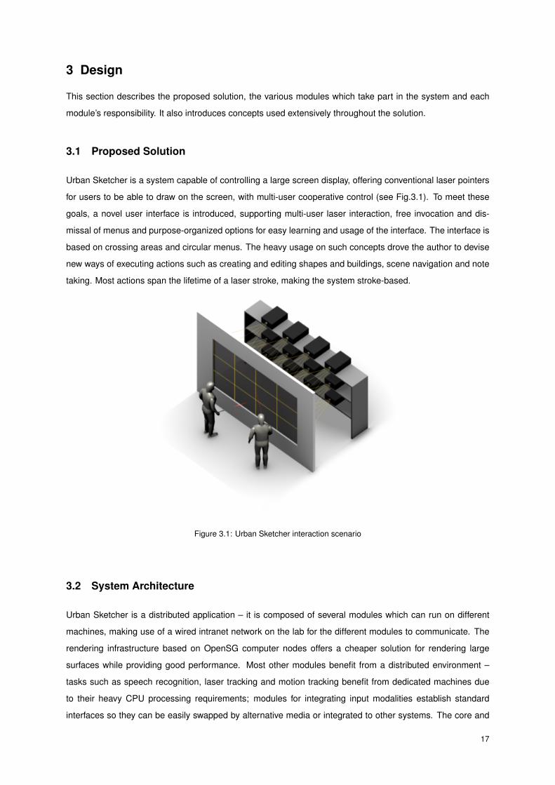
3.1 Proposed Solution
Urban Sketcher is a system capable of controlling a large screen display, offering conventional laser pointers
for users to be able to draw on the screen, with multi-user cooperative control (see Fig.3.1). To meet these
goals, a novel user interface is introduced, supporting multi-user laser interaction, free invocation and dis-
missal of menus and purpose-organized options for easy learning and usage of the interface. The interface is
based on crossing areas and circular menus. The heavy usage on such concepts drove the author to devise
new ways of executing actions such as creating and editing shapes and buildings, scene navigation and note
taking. Most actions span the lifetime of a laser stroke, making the system stroke-based.
Figure 3.1: Urban Sketcher interaction scenario
3.2 System Architecture
Urban Sketcher is a distributed application – it is composed of several modules which can run on different
machines, making use of a wired intranet network on the lab for the different modules to communicate. The
rendering infrastructure based on OpenSG computer nodes offers a cheaper solution for rendering large
surfaces while providing good performance. Most other modules benefit from a distributed environment –
tasks such as speech recognition, laser tracking and motion tracking benefit from dedicated machines due
to their heavy CPU processing requirements; modules for integrating input modalities establish standard
interfaces so they can be easily swapped by alternative media or integrated to other systems. The core and
17
middle-tier modules are modular mainly for abstraction purposes, dividing the complex problems of interface
and content management into manageable solutions.
For easing up the development and flexibility, the system is able to run on a simple laptop machine with
some of its modules disabled. On such setups the computer mouse generates events similar to the laser.
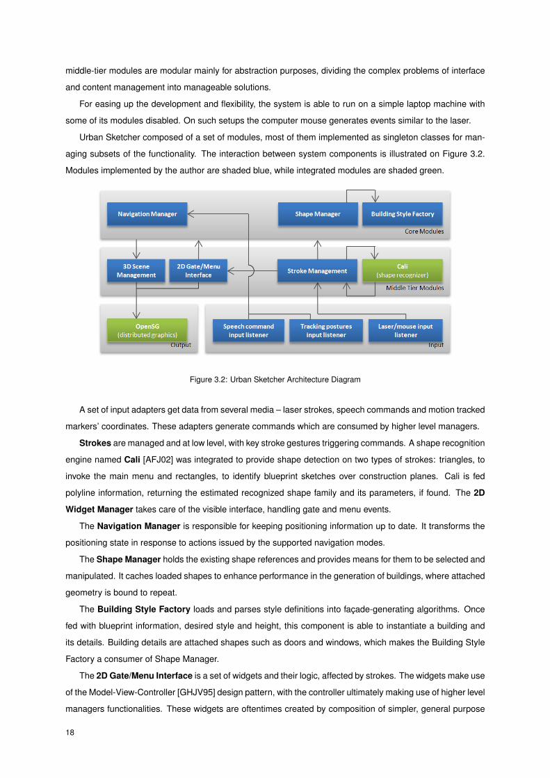
Urban Sketcher composed of a set of modules, most of them implemented as singleton classes for man-
aging subsets of the functionality. The interaction between system components is illustrated on Figure 3.2.
Modules implemented by the author are shaded blue, while integrated modules are shaded green.
Figure 3.2: Urban Sketcher Architecture Diagram
A set of input adapters get data from several media – laser strokes, speech commands and motion tracked
markers’ coordinates. These adapters generate commands which are consumed by higher level managers.
Strokes are managed and at low level, with key stroke gestures triggering commands. A shape recognition
engine named Cali [AFJ02] was integrated to provide shape detection on two types of strokes: triangles, to
invoke the main menu and rectangles, to identify blueprint sketches over construction planes. Cali is fed
polyline information, returning the estimated recognized shape family and its parameters, if found. The 2D
Widget Manager takes care of the visible interface, handling gate and menu events.
The Navigation Manager is responsible for keeping positioning information up to date. It transforms the
positioning state in response to actions issued by the supported navigation modes.
The Shape Manager holds the existing shape references and provides means for them to be selected and
manipulated. It caches loaded shapes to enhance performance in the generation of buildings, where attached
geometry is bound to repeat.
The Building Style Factory loads and parses style definitions into façade-generating algorithms. Once
fed with blueprint information, desired style and height, this component is able to instantiate a building and
its details. Building details are attached shapes such as doors and windows, which makes the Building Style
Factory a consumer of Shape Manager.
The 2D Gate/Menu Interface is a set of widgets and their logic, affected by strokes. The widgets make use
of the Model-View-Controller [GHJV95] design pattern, with the controller ultimately making use of higher level
managers functionalities. These widgets are oftentimes created by composition of simpler, general purpose
18
widgets.
Both shapes and 2D widgets know how to render themselves using OpenSG, so they both interact with it.
3D Scene Management handles the representation of the virtual world and is controlled by both the Shape
and Navigation managers.
3.3 Urban Sketcher Input/Output Communication
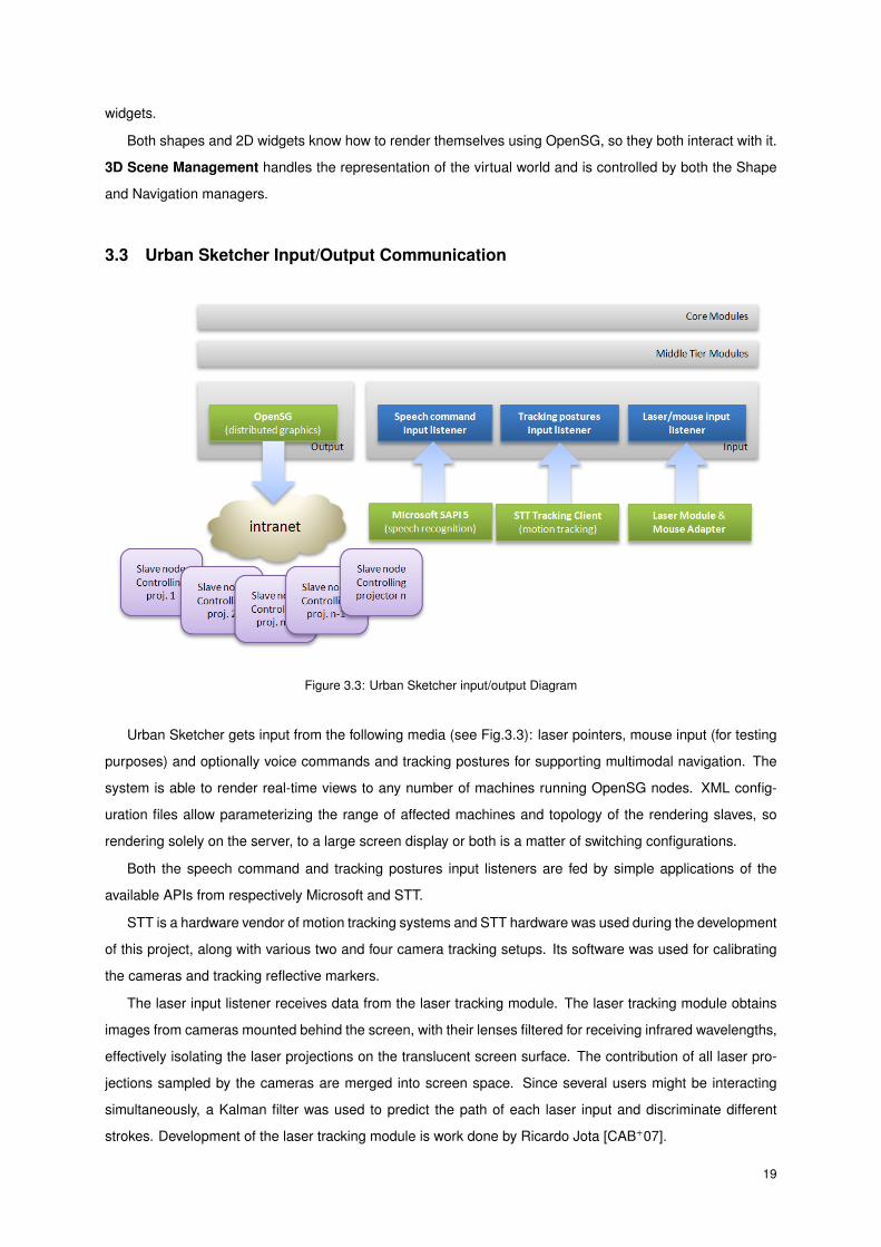
Figure 3.3: Urban Sketcher input/output Diagram
Urban Sketcher gets input from the following media (see Fig.3.3): laser pointers, mouse input (for testing
purposes) and optionally voice commands and tracking postures for supporting multimodal navigation. The
system is able to render real-time views to any number of machines running OpenSG nodes. XML config-
uration files allow parameterizing the range of affected machines and topology of the rendering slaves, so
rendering solely on the server, to a large screen display or both is a matter of switching configurations.
Both the speech command and tracking postures input listeners are fed by simple applications of the
available APIs from respectively Microsoft and STT.
STT is a hardware vendor of motion tracking systems and STT hardware was used during the development
of this project, along with various two and four camera tracking setups. Its software was used for calibrating
the cameras and tracking reflective markers.
The laser input listener receives data from the laser tracking module. The laser tracking module obtains
images from cameras mounted behind the screen, with their lenses filtered for receiving infrared wavelengths,
effectively isolating the laser projections on the translucent screen surface. The contribution of all laser pro-
jections sampled by the cameras are merged into screen space. Since several users might be interacting
simultaneously, a Kalman filter was used to predict the path of each laser input and discriminate different
strokes. Development of the laser tracking module is work done by Ricardo Jota [CAB+07].
19

3.4 Stroke-Based Input Interface
This section details the concepts used for the implementation of the system user interface.
3.4.1 Strokes
A stroke is the result of continuous input from one laser pointer, from the time the laser light button is pressed
until it is released. By using the laser detection module the system gets a stream of laser readings which
come sequentially tagged, that is, the module identifies with reasonable success when different strokes occur
simultaneously, returning both readings tagged with different stroke IDs. Even so, the module can not infer
whether different strokes came from the same source laser pointer. This limitation sets an important assump-
tion in our system – one can not know whether two strokes came from the same user, therefore operations
must take place during lifespan of a drawn stroke.
3.4.2 Gates
The most common activation action in current Graphical User Interface (GUI) computer interactions works by
displaying a button on the screen and the user activating it by pressing the pointer device’s button. Given that
users will rely on laser pointers to interact with the system’s GUI, a limitation derives from using them instead
of mice or track balls – while a user isn’t pressing the laser light button, neither the system nor the user can
accurately know where on the screen the laser is pointing to. In order for the user to see the laser projection
on the screen he must be pressing the button. This system requires a different GUI solution.
Based on prior research by Apitz and Guimbretière [AG04], the gate concept was implemented with slight
changes. The former idea was for actions to be activated by crossing an area by its explicitly drawn edges.
Some of the edges were red and other green, respectively enabling cancelation and confirmation actions.
The proposed gates work differently – they’re based on the action of crossing the middle of an area.
Gates have different visual states to suggest their internal state. No edge representation is required – once
in the verge of crossing the center of its area, the gate’s visual representation changes into focused state
and once the center is crossed it changes into activated state. Gates in Urban Sketcher have mostly circular
representations (when illustrated by icons), though text labeled gates exist too when the content is of dynamic
nature.
Internally a gate can be defined by an invisible line segment on the screen, bound by two visible extremes.
In order to activate it, one must draw a stroke which crosses the imaginary line segment, effectively crossing
the gate (see Fig.3.4). Gates can feature a text label or a suggestive image to symbolize the action they
perform. It was decided not to mix both representations to keep the interface uncluttered. To help novice
users to learn the function of each gate, a tooltip appears on gates when in focused mode, that is, when
approaching the gate’s area of influence without crossing it. This way the tooltip can be read and the action
optionally avoided.
Though gates are a formally rigid concept, its implementation is just an approximation: users can easily
stay oblivious of these, keeping as bottom line the idea of scribbling over the desired gate to activate it.
20

Figure 3.4: Gate activation
With a set of distinguishable and clearly purposed illustrations such as those designed for the Urban
Sketcher system, gates can easily recognized and their purpose learned. A gate can be repeatedly triggered
for precision operations, as several gates can be sequentially activated for achieving a complex state or action.
3.4.3 Menus
The menus of this system are ring-shaped, with its options spread along the ring in the form or gates. The
menu’s background ring is translucent so the main viewport remains visible. Different menus of similar func-
tionality have the same background color to aid user recognition (example: all navigation menus are green).
On the bottom-right area a curved label identifies the menu title. The top-right area features additional gates
for the dismissal of the menu, moving it around and returning to the main menu if at a subsequent level (see
Fig.3.5).
Figure 3.5: Menu and its areas
A lot of effort has been put for menus to be usable. On cases where menus offered a large number of
actions/options, those were clustered into modes to keep a conveniently small number of visible options. On
such menus, a set of gates at the left side of the menu represent the available modes. Selecting a different
mode is a matter of activating the corresponding illustrative gate.
Additionally to splitting menu gates into modes, gates can be grouped by purpose. On shape manipulation
menus, gates which share similar functionality are clustered into general purpose action gates. As an exam-
ple: move, move neighbors and extrude operations are clustered, as are bevel and beveled extrude. This
solution favors Hick’s Law as stated by Landauer and Nachbar [LN85], since it shows a smaller set of easily
distinguishable options, with the user setting the exact action he intends to reach from a smaller, filtered set
of gates.
21

3.4.4 Stroke Gestures
To invoke the main menu the user needs to draw a closed stroke resembling a triangle (see Fig.3.6). When
such stroke is drawn one main menu instance appears centered on it.
Figure 3.6: Main menu stroke
Besides menus derived from the main menu tree – which is invoked as we’ve just seen by drawing a
closed triangle stroke – there are menus which allow operating on existing shapes on the 3D world. These
are called contextual menus and they can be invoked by selecting a desired shape’s face or edge. To select
a face one has to draw a small stroke starting and ending inside the face. To select an edge one has to draw
a small stroke starting on one of the edge’s neighboring faces and ending at the remaining one, effectively
crossing the edge to select it (see Fig.3.7).
Figure 3.7: Edge and Face selection
3.4.5 Main Menu vs Contextual Menu
Every action which generates new shapes is accessible from the main menu. Actions which change existing
contents are available from context menus for face and edge. This segmentation rule was enforced so users
know where to search when in need of an untried operation.
3.5 Multimodal Input Interface
Using laser input allows the usage of all system’s functionalities. Even so, an alternative arm-tracking and
speech recognition command interface exists to enhance particular tasks. The arms are tracked by attaching
22

two reflective markers on each arm: one on each wrist and one close to each elbow. Speech commands are
obtained from a wireless headset attached to the user’s ear (see Fig.3.8).
Figure 3.8: A user with reflective markers and wireless headset
3.6 Content Creation Concepts
The interaction between 2D menu based interface and the underlying projection of the virtual scene required
a way of transferring selected options to the scene and a dynamic way of specifying the parameters of a
building so it can be easily created. To provide such mechanisms to work, two content creation concepts
were created.
3.6.1 Apply-to-Scene Creation
Several menus allow the selection of options (such as shapes or building styles), triggered from a menu.
The destination of such choice must be mapped into an object on the scene, therefore the concept of drag
and drop was extended – the remaining of a stroke where such a selection is made server to point out the
destination object, with the tip of the stroke being the preview location while the stroke is taking place.
To create a new object on the scene one has to perform a stroke which activates the desired shape
creation gate (cube for instance) and continue the stroke onto the desired location where the shape is to rest.
As soon as the gate is activated the shape appears on top of the stroke and keeps following the stroke until
it ends, offering a preview of the location where is would rest if the stroke ended that particular moment (see
Fig.3.9). To figure out the actual location for the shape during the task the shape is iteratively collided against
the existing scene geometry so it stays in touch with the environment.
23

Figure 3.9: Apply-to-scene procedure - creating a shape
Figure 3.10: Building creation procedure
3.6.2 Instancing a Building
To create a building one has to feed the system three parameters: building style, blueprint and height. Due
to the system decision for stroke-driven actions without global state, these three parameters are given with
the minimum strokes (two), as described next. From a menu the list of supported building styles is presented
to the user, each style a different gate. Once activating the desired style the user starts an apply-to-scene
process, moving a construction plane which must be put where the blueprint is to be drawn. The user draws a
closed rectangle representing the blueprint and after closing it continues the stroke upwards in order to define
the building’s height. Once the stroke ends the building is generated according to the given parameters. The
construction plane has now carried out its purpose and therefore is terminated (see Fig.3.10).
24
4 Implementation
The execution of the projected features described earlier on is the focus of this section. Functionalities are
grouped by purpose and their details explained and discussed. The several offered navigation modes, content
creation and editing features and review features are described. To close this section, an alternative work flow
is proposed for taking advantage of the Urban Sketcher features.
4.1 Navigation
Good navigation modes are paramount for the success of any 3D based system. The nature of this system,
with the availability of a large screen, stroke-controlled input and the aim of allowing unexperienced users to
take control of the system quickly, made this requirement even more relevant.
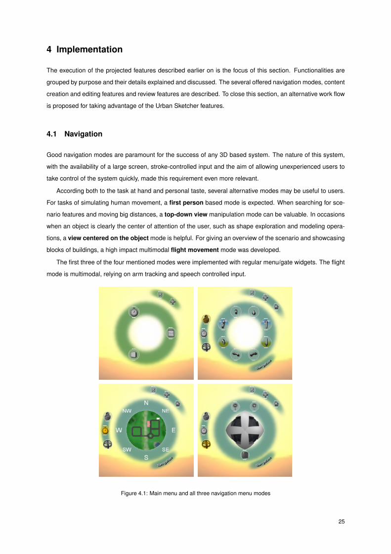
According both to the task at hand and personal taste, several alternative modes may be useful to users.
For tasks of simulating human movement, a first person based mode is expected. When searching for sce-
nario features and moving big distances, a top-down view manipulation mode can be valuable. In occasions
when an object is clearly the center of attention of the user, such as shape exploration and modeling opera-
tions, a view centered on the object mode is helpful. For giving an overview of the scenario and showcasing
blocks of buildings, a high impact multimodal flight movement mode was developed.
The first three of the four mentioned modes were implemented with regular menu/gate widgets. The flight
mode is multimodal, relying on arm tracking and speech controlled input.
Figure 4.1: Main menu and all three navigation menu modes
25
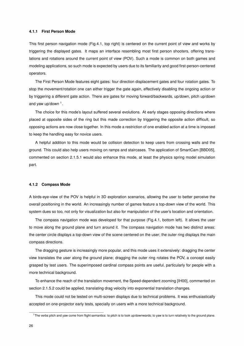
4.1.1 First Person Mode
This first person navigation mode (Fig.4.1, top right) is centered on the current point of view and works by
triggering the displayed gates. It maps an interface resembling most first person shooters, offering trans-
lations and rotations around the current point of view (POV). Such a mode is common on both games and
modeling applications, so such mode is expected by users due to its familiarity and good first-person-centered
operators.
The First Person Mode features eight gates: four direction displacement gates and four rotation gates. To
stop the movement/rotation one can either trigger the gate again, effectively disabling the ongoing action or
by triggering a different gate action. There are gates for moving forward/backwards, up/down, pitch up/down
and yaw up/down 1.
The choice for this mode’s layout suffered several evolutions. At early stages opposing directions where
placed at opposite sides of the ring but this made correction by triggering the opposite action difficult, so
opposing actions are now close together. In this mode a restriction of one enabled action at a time is imposed
to keep the handling easy for novice users.
A helpful addition to this mode would be collision detection to keep users from crossing walls and the
ground. This could also help users moving on ramps and staircases. The application of SmartCam [BBD05],
commented on section 2.1.5.1 would also enhance this mode, at least the physics spring model simulation
part.
4.1.2 Compass Mode
A birds-eye-view of the POV is helpful in 3D exploration scenarios, allowing the user to better perceive the
overall positioning in the world. An increasingly number of games feature a top-down view of the world. This
system dues so too, not only for visualization but also for manipulation of the user’s location and orientation.
The compass navigation mode was developed for that purpose (Fig.4.1, bottom left). It allows the user
to move along the ground plane and turn around it. The compass navigation mode has two distinct areas:
the center circle displays a top-down view of the scene centered on the user; the outer ring displays the main
compass directions.
The dragging gesture is increasingly more popular, and this mode uses it extensively: dragging the center
view translates the user along the ground plane; dragging the outer ring rotates the POV, a concept easily
grasped by test users. The superimposed cardinal compass points are useful, particularly for people with a
more technical background.
To enhance the reach of the translation movement, the Speed-dependent zooming [IH00], commented on
section 2.1.5.2 could be applied, translating drag velocity into exponential translation changes.
This mode could not be tested on multi-screen displays due to technical problems. It was enthusiastically
accepted on one-projector early tests, specially on users with a more technical background.
1The verbs pitch and yaw come from flight semantics: to pitch is to look up/downwards; to yaw is to turn relatively to the ground plane.
26

4.1.3 Examine Mode
When a program has the purpose of supporting the exploration of the shape of an object, an object-centric
view is offered. On simple scenarios the object occupies the center of the world and the view rotates around
the world’s center. Urban Sketcher allows the center of attention to be dynamically set to any object of the
world.
The examine mode is based on moving along the space close to the center of attention (Fig. 4.2). It
features three gates and a center sphere (see Fig.4.1, bottom right).
The user is offered a gate so a new center of attention can be set. This action is performed by activating
the gate and ending the same stroke at the desired center of attention. Once this is done, a spherical widget
allows performing rotations around the object by dragging the sphere. Two additional gates allow zooming in
and out to reveal more or less detail, respectively.
For the users who got the grip of this mode, it has revealed itself a very efficient way for both looking around
and repositioning oneself. Only laser-tracking problems inhibited a better use of repeatedly re-centering
operation for movement.
Figure 4.2: Concept supporting examine mode
4.1.4 Multimodal Flight Mode
The Multimodal Flight Mode is an alternative navigation mode devised by the author to provide an alternative
way of moving on the world. This mode relies on arm gestures to control flight speed, rotation and altitude
shift. These operations are smoothly applied by continuous arm tracking and the application of a set of simple
rules to identify the user’s purpose. This mode doesn’t rely on laser input and can be enabled or disabled by
speech commands.
To implement such mode the 3.5 Multimodal Input Interface was used. Since it affects the point of view,
this task can not be performed by several people simultaneously, therefore unlike most of the system this
navigation mode has global states – the user might be either stationary of flying (see Fig.4.3).
The user starts interacting by having his arms extended toward the screen. In order to begin flying the
command “Begin flying” must be given. To stop at any time one only needs to say “Stop flying” 2.
2Although semantically inconsistent, the words begin and stop were used after performing speech recognition tests with both
start/stop, begin/end and begin/stop commands, concluding that this combination had the better recognition ratio.
27

Controlling flight speed works by measuring the distance between hands – the closer they are to each
other the faster the flight speed is. If the arms do a wide enough angle between them the flight comes to
an halt. Changing the flight orientation relatively to the ground is achieved by setting the arms angle with
the ground at opposing directions, with a bigger difference between these angles generating a faster rotation
movement. If the user wants to turn right, for instance, he has to raise the left arm and lower the right one.
To change flight altitude both arms must be oriented in the same direction relatively to the ground plane –
either both raised or lowered. Again, the higher the angle is from the original forward pose position the bigger
the flight altitude shift is.
Figure 4.3: Flight mode: controlling speed and direction
4.1.5 Other possible navigational modes
In addition to the navigation modes made available in the system, the following modes might be of use.
The multimodal “go-to-here” , with a combination of laser pointing to the destination and speech command
to trigger the movement. This mode was requested on the final tests.
The stroke-defined path, as suggested on the Path Drawing [IKMT98], discussed on section 2.1.5.3. It
would be useful to experiment this mode, but the requirements for its application were unmatchable: Igarashi’s
system uses a third person view with explicit avatar rendering. Moreover, Urban Sketcher stroke-based in-
terface makes it hard to map a movement path stroke – this would require multimodal integration with a
“move-like-this” speech command.
During the navigation tests at Glasgow, users suggested the addition of a list of recorded locations. The
idea was for the user to get to a new and relevant point of view, such as a good façade angle, and trigger the
record location action. Recorded locations might be tagged by either speech recognition (example: “record
location stadium front now”) or scribble text recognition. Later on resuming to the saved location would be a
matter of invoking the metadata recorded earlier.
28

4.2 Creating Content
The system’s interface offers three families of shapes which can be instanced on the scene: primitives, a set
of previously generated shapes and set of known building styles from which to create buildings. Primitives
are the most versatile shapes since they support face and edge manipulation operations. All shapes support
simple transformations and cloning.
One uses building styles to create buildings on the scene. A library of generated shapes such as people
and trees serve as assets to populate the scene with details. Primitives can be instanced as is or as building
ground for custom shapes.
Figure 4.4: Shape menu
4.2.1 Shape Internal Structure
A shape in this system was implemented as a boundary representation (B-REP) [Req80]. This structured
was used due to its simple translation to visual representation and ease of shape modification. To support
several geometry operations an additional constraint was enforced – all faces have four edges and therefore
each edge has at most two neighboring faces.
The shape’s surface is defined by two data structures: an indexed array of vertex positions, used to
store the position of each shape vertex; an indexed array of faces, with every face being a counter-clockwise
ordered set of four vertex indices. An edge in the system is a pair of ordered vertex indices. The ordering
step makes the edge direction irrelevant for the edge definition, a desired feature.
Besides this information, each shape manages an auxiliary edge map. This map associates a face to its
bounding edges and vice versa. The edge map allows efficient queries to be performed, such as: which faces
are bound by edge x; what is the opposite edge of edge x in face y; which other edges beside edge x make
part of the face loop. These are all relevant queries for the implementation of internal shape operations.
Shapes offer methods to update their visual representation. Shapes also make available a set of geometry
modifying operations – these are not only exposed to the user via UI, but also used by templates, as further
explained.
In order to support undo operations, the memento design pattern [GHJV95] was implemented. A shape
memento stores the internal structure of a shape at one point in time and is able to restore that shape’s state
29
later on, if so requested. A shape has a stack of mementos so multiple undo steps can be executed.
4.2.2 Shape Instancing
The instancing of shapes works using the Apply-to-Scene concept described on section 3.6.1 Apply-to-Scene
Creation and the respective Figure 3.9. Every gate of this type has a small arrow running outwards as a hint
to the user of this feature. The user activates the gate of the desired shape and ends the stroke where he
wants it to rest.
4.2.3 Shape Templates
A template is a shape recipe with input parameters, defining a way of obtaining the desired shape by applying
a set of operations, with the passed parameters affecting the final geometry. Templates are not directly
exposed on the system UI. They’re currently used solely to generate building ceilings, but could be extended
for other means.
Templates make use of shape exposed operations to generate the final shape. For instance, the creation
of a two-slanted ceiling starts from a regular box shape, applying a sequence of two edge move operations.
Additional templates could be easily created to aid in the generation of repetitive structures such as railings
and staircases.
4.2.4 Building Style
Buildings with the same purpose share most of their properties – colors, floor height, façade appearance,
ceiling type, etc. Such buildings differ the most on their number of floors and façade dimensions.
To streamline the generation of building, the concept of building style was developed and implemented.
In Urban Sketcher a building is a complex shape composed of side walls, a ceiling and a set of attached
shapes enriching the façades with details such as doors, windows and balconies.
A building style is a set of rules and parameters, written according to a developed XML format. The
system comes with a set of styles, with the user choosing the desired style to apply to the building he’s about
to create. The building style factory is able to parse style definitions, instantiating and distributing attached
shapes to make up the façades according to the chosen style.
4.2.4.1 Building Style Structure
The building style grammar defines building parameters such as floor-height, ceiling parameters and color-
intervals for the walls and ceiling. It also defines a set of rules for the generation of the facade attachments
that make up the final facades, defined by the optional front-facade and the facades elements.
One can define the layout of a floor with the layout element, composed of four sections: left, center, right
and other. Of these only the other section is required and the layout works by trying to fill the facade space
with center, left and rights’ contents if those are present, repeating other’s contents for filling the remaining
space.
30

Inside these sections one can put any of the us-elements: atom, group, sequence and random. An
atom is the simplest us-element, having the attributes type, spacing and height. The type parameter defines
which shape to instantiate on the facade, spacing how many length of the facade it will consume and height
can be used to shift the shape upwards (to move a window, for instance).
The remaining us-elements allow combining us-elements. A set of us-elements inside a group create all
content on the same place and measure the longest of its children. A set of us-elements inside a sequence
create all children one after the other. The random us-element is similar to group, but has the attribute odds,
a set of comma separated ratios defining the probability of each child to be picked.
Several floors can share the same layout. To apply a layout to one or a set of floors, the floor-span
element exists. It can have either the at attribute defined or both min and max, resulting in the application of
the enclosed layout to all the floors in the interval.
One can also define a different facade style for the front facade with the element front-facade. This is
useful when one wants to apply columns and doors to one facade but not the remaining ones.
An example of a complete building style can be found on appendix A. The resulting building is depicted on
Fig. 4.5.
Figure 4.5: Resulting building of residential style. Several components are highlighted for comprehension.
4.2.5 Instancing Buildings
Once the building parameters have been gathered by the interface, the building needs to be generated. Sec-
tion 3.6.2 Instancing a Building describes the procedure along with Figure 3.10. First the stroke is projected
onto the construction plane and parsed by the shape recognizer as a rectangle. The recognized rectangle
dimensions serve as the blueprint which is extruded upwards for the measured height. Then the building
facades are generated according to the chosen style grammar and so is the ceiling. The style grammar is
fed each facade’s dimensions and returns a set of spacings and facade elements that must be instanced
according to the rules defined in the style (see Fig.4.5). To minimize the facade attachments in memory, a
map of loaded attachments is managed so only the first instance of any attachment is loaded. Appendix A
lists the residential style depicted above.
31

4.3 Editing Content
All shapes in the system are made of four-edged faces and all shapes are closed surfaces. Operations such
as the split by face loop rely on these properties. Each shape computes each edge’s neighboring faces
(always two) and therefore each face’s neighboring faces, forming an auxiliary structure called the edge map,
used for optimized queries for neighbors.
4.3.1 Face and Edge Selection
When a stroke finishes its start and ending points are projected onto the scene’s available geometry. If these
two points lie on the same face of the same object that face is selected and the face contextual menu appears
(see Fig.4.6 bottom).
Figure 4.6: Edge and Face selection and their contextual menus
If the stroke start and ending points lie on different but neighboring faces of the same shape, the edge
between those faces is selected and the edge contextual menu appears (see Fig.4.6 top).
4.3.2 Determining and Selecting Directions
In order to keep the interface simple and to minimize the number of steps needed to perform an operation,
a set of directions is estimated for edge and face selections – these are believed to be the most frequently
needed vectors for shape operations. When an edge is selected the computed directions are the edge out-
wards normal and the directions from the edge along its neighboring faces. When a face is selected the
computed directions are the face normal along with the four directions from the center of the face to each of
its neighboring faces (see Fig.4.7).
32

If an operation requires the user to select a direction from the user the computed directions are displayed
centered on the selected aspect and color coded. The interface relies on the user to keep drawing the stroke
after the operation is triggered so the remaining of the stroke data parameterizes the operation.
Figure 4.7: Face directions
4.3.3 Shape Operations
This system has the goal of offering an easy yet reasonably powerful interface for modeling shapes. The
shape’s internal structure was planned so both face and edge-based operations could be performed. Every
operation takes the triggering element (edge or face) as input parameter. Most operations require additional
information, obtained by extracting the user’s stroke direction and length. This interaction model keeps the
number of stroke steps minimal while offering valid functionality for each operation.
The list of supported operations appears next, with them grouped by functional element – the whole object,
one of its faces or one of its edges. Figure 4.8 illustrates the application of these operations.
4.3.3.1 Object Operations
Available object operations are translation, rotation, scale and clone. The translation operation accepts
a delta vector, applying it in real-time on one of the five directions: normal and the four surrounding edge
directions. Rotation and scale operations take only the stroke length – scale transforms all three axes
proportionally; rotation can take the triggered face’s normal as axis of rotation or can default to the YY axis for
simplification, since most urban changing operations make use of this rotation. An additional object operation
is cloning. The clone operation works like a regular translation, leaving behind a copy of the original shape.
Since it uses the face normal and face-bounding edges’ directions, the cloning operation allows efficient
generation of building blocks and repetitive structures.
4.3.3.2 Face Operations
The move operation uses the same directions as translation, changing the position of the face vertices. Move
neighbors identifies neighboring faces having a smaller angle with the selected face than a defined threshold,
applying a move operation to the set of affected faces. Extrude generates a new face for every face’s edge
and offers only the normal direction for moving the face outwards/inwards. Bevel scales the face vertices,
33

Figure 4.8: Shape operation example applications
preserving inner angles. The beveled extrude operation exists solely for convenience, generating a set of
faces and applying an immediate bevel operation to provide a simple way of creating relief details on faces for
chimneys or windows.
4.3.3.3 Edge Operations
Edges can be moved, with the offered directions being the edge normal and the opposite edges along the
neighboring faces. This is illustrated on Figure 4.7 and described on section 4.3.2.
The split along face loop operation allows increasing the detail of a shape by cutting new faces along
the center of the implied edges.
On both edge and face context menus there’s an option to toggle the visibility of the shape edges.
4.3.3.4 Possible Additions
The set of given operations offers a competent tool set for modeling simple shapes. During tests users have
found several creative ways of modeling the requested shapes. Even so, multi-selection operations would be
a nice addition to the tool set. In early prototypes of the system the closed lasso stroke was used to select
multiple objects, which proved problematic since users inadvertently selected too many objects. Furthermore,
using multi-selection for shape operations limited the direction seeking algorithms described above, which are
key to the proposed simplified interface.
34
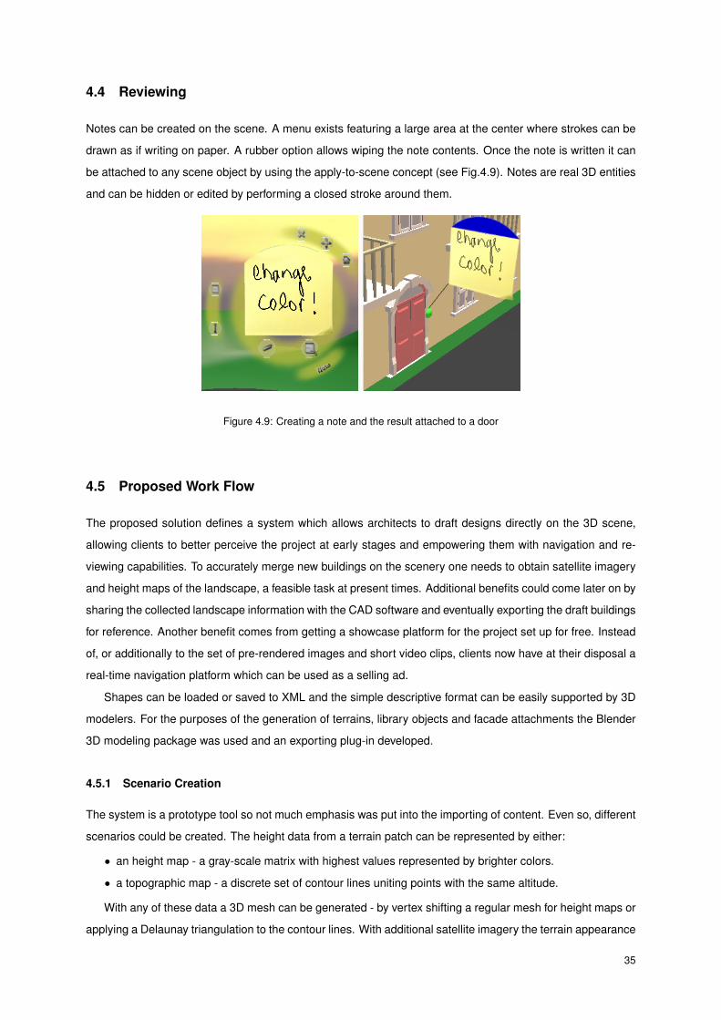
4.4 Reviewing
Notes can be created on the scene. A menu exists featuring a large area at the center where strokes can be
drawn as if writing on paper. A rubber option allows wiping the note contents. Once the note is written it can
be attached to any scene object by using the apply-to-scene concept (see Fig.4.9). Notes are real 3D entities
and can be hidden or edited by performing a closed stroke around them.
Figure 4.9: Creating a note and the result attached to a door
4.5 Proposed Work Flow
The proposed solution defines a system which allows architects to draft designs directly on the 3D scene,
allowing clients to better perceive the project at early stages and empowering them with navigation and re-
viewing capabilities. To accurately merge new buildings on the scenery one needs to obtain satellite imagery
and height maps of the landscape, a feasible task at present times. Additional benefits could come later on by
sharing the collected landscape information with the CAD software and eventually exporting the draft buildings
for reference. Another benefit comes from getting a showcase platform for the project set up for free. Instead
of, or additionally to the set of pre-rendered images and short video clips, clients now have at their disposal a
real-time navigation platform which can be used as a selling ad.
Shapes can be loaded or saved to XML and the simple descriptive format can be easily supported by 3D
modelers. For the purposes of the generation of terrains, library objects and facade attachments the Blender
3D modeling package was used and an exporting plug-in developed.
4.5.1 Scenario Creation
The system is a prototype tool so not much emphasis was put into the importing of content. Even so, different
scenarios could be created. The height data from a terrain patch can be represented by either:
• an height map - a gray-scale matrix with highest values represented by brighter colors.
• a topographic map - a discrete set of contour lines uniting points with the same altitude.
With any of these data a 3D mesh can be generated - by vertex shifting a regular mesh for height maps or
applying a Delaunay triangulation to the contour lines. With additional satellite imagery the terrain appearance
35

could also be approximated by vertex coloring or texture projection application.
4.5.2 Building Style Creation
New attachment shapes could be created using Urban Sketcher itself or an auxiliary 3D modeler. Creating a
building style is a matter of editing the style grammar, defining ceiling type, colors, floor height and most of all
the layout for the building floors using existing and/or newly created attachments.
36

5 EvaluationThe system has evolved with several user tests along the way. During the course of the IMPROVE program
several features were tested and enhanced. The shape modeling operations, examine navigation mode and
building creation module were developed later on and were focus of the final user tests.
5.1 Intermediate Tests
Early stages of development of Urban Sketcher were supported by the European Union’s IMPROVE1 consor-
tium. IMPROVE joined universities, hardware manufacturers and design studios in the areas of architecture
and car design. Early prototypes of the interface and most of the navigation and reviewing functionalities
featured on Urban Sketcher were developed during the period of the program. The interface, then called
ImmiView, was used for experimenting large screen display, tablet PC and head-mounted displays on tasks
of architecture design and reviewing sessions.
IMPROVE was beneficial for the large brainstorming sessions which defined several of the concepts avail-
able today on Urban Sketcher, as with the series of User Tests which took place both in Glasgow Scotland and
Lisbon Portugal. These tests served to get feedback on interface design and the navigation modes available
at the time: first person and compass modes and the multimodal flight mode.
Several IMPROVE related publications were written as result of this project, such as [SSG+07a] [SSG+07c]
[SSG+07b].
5.1.1 Test Environments
The first Glasgow test occurred between the 16th and the 19th of April 2007 at the Glasgow Caledonian
University. A hand-made screen frame was mounted and one infrared camera calibrated behind the screen.
One regular XVGA projector was used with forward projection.
The Lisbon tests took place between the 11th and 12th of June 2007 and focused on evaluating collab-
oration tasks. For these tests the Instituto Superior Técnico Multimedia Lab was used[AGC+05]. It has a
structure of 4 by 3 projectors behind a translucent screen. The projection was performed from the back, with
two infrared cameras mounted on the projector structure so a bigger portion of the screen could be tracked.
The second Glasgow test occurred between the 16th and 19th of July 2007 at The Lighthouse building.
This test was performed on a portable display and a projector set up for back projection along with one infrared
camera for laser tracking. Four STT system cameras and reflective markers were used for tracking the user’s
arms. One Microsoft ZX-6000 wireless headset microphone was used to get the user’s voice and the Microsoft
Speech API 5.1 American English version performed speech recognition to identify a set of commands issued
by users.
5.1.2 Results
The test at Caledonian provided feedback about the first person and compass navigation modes. The layout
of the first person mode was changed as a result of this test – its gates layout used to mimic the three axes for1Improving Display and Rendering Technology for Virtual Environments – http://www.improve-eu.info
37
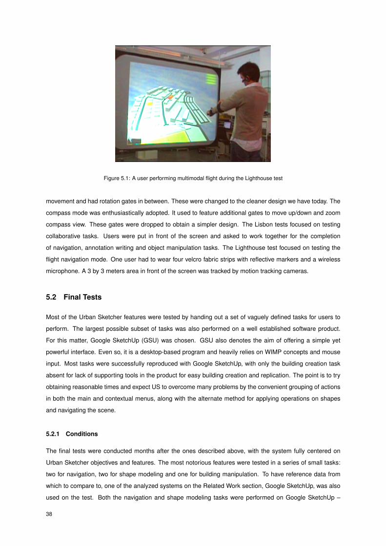
Figure 5.1: A user performing multimodal flight during the Lighthouse test
movement and had rotation gates in between. These were changed to the cleaner design we have today. The
compass mode was enthusiastically adopted. It used to feature additional gates to move up/down and zoom
compass view. These gates were dropped to obtain a simpler design. The Lisbon tests focused on testing
collaborative tasks. Users were put in front of the screen and asked to work together for the completion
of navigation, annotation writing and object manipulation tasks. The Lighthouse test focused on testing the
flight navigation mode. One user had to wear four velcro fabric strips with reflective markers and a wireless
microphone. A 3 by 3 meters area in front of the screen was tracked by motion tracking cameras.
5.2 Final Tests
Most of the Urban Sketcher features were tested by handing out a set of vaguely defined tasks for users to
perform. The largest possible subset of tasks was also performed on a well established software product.
For this matter, Google SketchUp (GSU) was chosen. GSU also denotes the aim of offering a simple yet
powerful interface. Even so, it is a desktop-based program and heavily relies on WIMP concepts and mouse
input. Most tasks were successfully reproduced with Google SketchUp, with only the building creation task
absent for lack of supporting tools in the product for easy building creation and replication. The point is to try
obtaining reasonable times and expect US to overcome many problems by the convenient grouping of actions
in both the main and contextual menus, along with the alternate method for applying operations on shapes
and navigating the scene.
5.2.1 Conditions
The final tests were conducted months after the ones described above, with the system fully centered on
Urban Sketcher objectives and features. The most notorious features were tested in a series of small tasks:
two for navigation, two for shape modeling and one for building manipulation. To have reference data from
which to compare to, one of the analyzed systems on the Related Work section, Google SketchUp, was also
used on the test. Both the navigation and shape modeling tasks were performed on Google SketchUp –
38

building manipulation isn’t supported by the system.
It is important to highlight that Google SketchUp is a commercial product with several years of development
and is based on familiar interface concepts and tested on a regular computer screen with keyboard and mouse
input. On the other hand Urban Sketcher tests are to be performed on a large screen display using a laser
pointer and an ad hoc laser tracking system, with a set of novel interface concepts.
5.2.2 Test Environment
The final tests took place on the Instituto Superior Técnico Multimedia Lab between the 28th of June and 1st
of July 2008. The tests were performed with the same environment as the Lisbon IMPROVE test described
above – a large display screen of 4 by 3 projectors on a translucent screen. The laser tracking system was
calibrated to get only laser information from about 1/3 of the screen area. During the 4 days period they took
place, 16 users performed the tasks described below. The task description documents and questionnaires
can be found on appendix B. Out of the user sample, 94% of the users had college degrees, 31% were women
and the average user age was 37 years old. This is a population with high levels of education. On the other
hand the average age is of adult users, not prone to new interface metaphors and with less precise motor
skills.
User tests were performed individually and took between 60 and 90 minutes. First a preliminary ques-
tionnaire composed of five close-ended questions was handed out and filled, to assert the past experience of
users on topics of relevance. Then the purpose of the project was presented along with a tutorial of Urban
Sketcher’s features and how to use them. After a small hands-on period the tasks were given to the user to
perform on the Urban Sketcher system. Then a tutorial was given of the Google SketchUp program, focused
on the features necessary to perform the tasks. After a small hands-on period the navigation and model-
ing tasks were performed on the Google SketchUp system. To finalize the test, the final questionnaire was
handed out and filled. It was composed of 13 close-ended scaled questions and five open-ended questions,
the former to obtain feedback regarding the Urban Sketcher system and the latter focused on comparing the
two systems.
5.2.3 Results
During the tests, task completion times were measured in minutes and both user errors and system unex-
pected events were logged. On table 5.1 the summary of times for completing all the tasks is listed. Chart
5.2 is a box and whiskers chart, depicting the time users took to complete the tasks. The whiskers define the
range of sampled results, while the box ends mark the 25th and 75th percentile of the data. The diamond
marks the average value. Blue boxes were used on Urban Sketcher, gray ones on Google SketchUp.
Tasks performed on both systems were expected to show discrepancies in both completion time and
number of errors. Most users are proefficient working with the mouse. The ad-hoc laser tracking system
used in the test: didn’t map the whole screen; had calibration issues, particularly near the edges; had a low
sampling rate (about 20 Hz).
The questionnaires feature a total of 18 close-ended scaled questions. These had to be graded from 1 to
39

Table 5.1: Task completion times on Urban Sketcher and Google SketchUp
Figure 5.2: Box and whiskers charts comparing task completion times on both systems
6, with 1 meaning complete disagreement to/infrequent statement and 6 completely agree/very frequent. Out
of these questions, the first five tested the users past experience in relevant topics and the remaining 13 got
feedback on using Urban Sketcher. Additionally, five open-ended questions were given at the end, focusing
on the comparison of both systems.
The translated questions and their results are listed on tables 5.2 (close ended) and 5.3 (open ended). Its
responses were analyzed and clustered. To aid in the interpretation of these results, charts 5.3 and 5.4 were
respectively created.
40
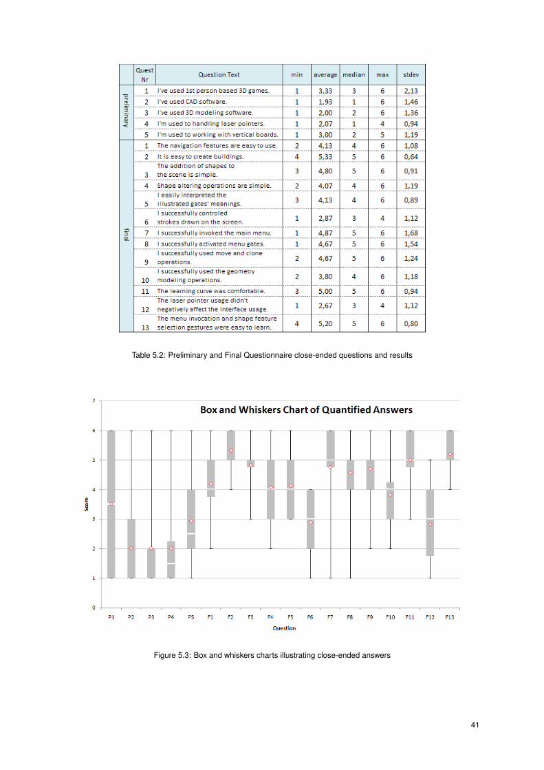
Table 5.2: Preliminary and Final Questionnaire close-ended questions and results
Figure 5.3: Box and whiskers charts illustrating close-ended answers
41

Table 5.3: Final Questionnaire open-ended questions and clustered answers
Figure 5.4: Pie charts illustrating the clustered open-ended answers
5.2.3.1 Task Performance and Issues
When looking at the time it took users to complete the tasks, Urban Sketcher took between 50% and 83%
more time than Google SketchUp. This difference is small given that users performed Urban Sketcher tasks
standing up, using a novel user interface and handling a laser pointer on a limited tracking area.
The navigation tasks were the first to perform, with users getting acquainted with the interface. Some
undesired context menus were invoked at these first tasks, probably due to users drawing too fast. When this
42

happens, the laser tracking module segments the real strokes into small segments, misleading the system
into recognizing these events as context menu invocations.
It was on the modeling tasks that differences between the systems were less notable. This can be imputed
to the carefully crafted modeling operations and their menus. Some users took more time grasping the concept
of stroke-long operations and their requirement to keep the stroke active after triggering the operation to set
its direction and length. The main menu stroke gesture (a closed triangle) had worse recognition success
rate on these operations. This might have to do with users performing more context menu invocations and
temporarily forgetting the correct gesture to invoke the main menu or drawing triangles more roughly.
The building creation task was performed very smoothly in regard to its complexity. Only a small set of
individual problems occurred and users felt satisfied by the ease at which they instanced buildings and assets.
5.2.3.2 Close-ended Answers Analysis
The familiarity of users with 3D software and CAD proved to be low and the usage of 3D first person games
disparate (P3, P2, P1). Few users were used to handling laser pointers and some of them used vertical
boards occasionally – this might be explained by the presence of two teachers on the user test (P4, P5).
Users found navigation, creation of buildings and shape creation and modeling fairly easy (F1, F2, F3,
F4). The illustrated gates were given a good recognition ratio and their activation was successful (F5). Menu
invocation and shape feature selection were easy to learn (F7, F8). Both the move and clone operations were
credited as functional and the learning curve classified comfortable (F9, F11).
Users diverged the most when asked about the success rate at which they controlled their strokes (F6).
This problem can be credited to laser tracking limitations on both tracked screen area and slow capturing
frequency. These originated visual deviations between real stroke and its interpretation, especially notable
near the tracking boundaries. Due to the slow capturing frequency, strokes had to be drawn slowly, otherwise
they’d get segmented. This problem was emphasized when performing apply-to-scene operations such as
re-centering the examine center of interest or instancing new shapes which required continuity of stroke.
5.2.3.3 Open-ended Answers Analysis
Most users held the laser tracking facilities responsible for some dissatisfaction and slowness in performing
the tasks when comparing with Google SketchUp (81% of the users, O1). 13% of the users felt the novel
interface unfamiliar therefore harder to master for a novice user while only 6% elected Google SketchUp as
the best interface (O2). 94% of the users enjoyed the capacity of invoking menus as needed – of these, 13%
pointed out that the navigation menu could be fixed to the screen due to its constant usage, though this screen
allocation problem was result solely of the limited tracked area of screen – if all screen was being tracked the
menu could have remained there the whole time (O3). Out of all the users, only 25% state having trouble with
the modeling tools. This is satisfactory since many users have shown low confidence at first when asked to
perform the modeling tasks, ending up completing them with success and reasserting their beliefs regarding
such tasks (O4). Several users felt this interface could be very effective on several domains for controlling
large screen displays.
43
It was shown that a stroke-based interface is capable of offering a set of complex actions and navigation
modes to novice users with them successfully performing tasks in reasonable time frames. Most users iden-
tified the laser tracking input as an obstacle to an even better experience. This is a technical limitation which
doesn’t invalidate the application of these concepts and interface with other technologies such as large multi
touch surfaces.
44

6 Conclusion
The author designed and implemented a system named Urban Sketcher, whose purpose is to provide archi-
tects and average users a way of making good use of large scale displays for the creation of urban sceneries.
Users can navigate the scene using several modes, create and edit content such as buildings and custom
shapes and review the scene by attaching notes to surfaces.
The system was implemented as a distributed modular application. It was designed to support collabora-
tive usage and laser pointers were used as main input device. A novel user interface was devised, controlled
by stroke input, with gestures, circular menus, area crossing activation (extending the work of [AG05]). The in-
terface supports also multimodal modes – speech commands and arm tracking were used to offer an alternate
way of moving the scene – the multimodal flight mode.
A building creation method was developed to provide a faster way of generating buildings based on their
style, described by a custom XML format for describing façade appearance, ceiling and shape details layout.
The set of provided tools for shape modeling proved sufficient for modeling simple shapes, with users
figuring out many creative ways of obtaining the requested shapes.
6.1 Results
The system was tested on several occasions for validation of navigation modes, the multimodal mode and the
building and modeling tools. Since there’s no clear contender in this area, tests were conducted by comparing
tasks performed by users on Urban Sketcher on a large screen display against the same tasks performed on
Google SketchUp on a regular computer with keyboard and mouse input. Users enjoyed working with the
system and their performance completing the tasks was at the most 50% slower when comparing to their
results on SketchUp, an exciting result given the differences between both systems. Users were introduced
to a new way of input, a novel user interface and a set of supported features uncommon to desktop software.
The stroke-based interface and menus proved capable on large screen environments and the building creation
and shape modeling features were learned and used efficiently.
6.2 Main Contributions
This project introduced a new way of instantiating buildings using two strokes – one for defining the style and
construction plane and the other to set the blueprint and facade height dimensions. The architecture styles
set can be enriched by users, with the system supporting a custom XML format to define their layout and
characteristics.
In cases where custom 3D shapes are needed to enhance a particular aspect of a building, users have
the ability to creating custom shapes. These can be edited by a small set of face and edge operations, crafted
to cover the most common needs of geometry modeling. The most useful directions are estimated and made
available for the user to manipulate the shape’s faces and edges, without the overhead of dozens of menu
commands and parameters. Shapes can also be generated from other 3D applications such as the Blender
45

3D Modeler, for which an exporter plug-in was generated, allowing the integration of externally created 3D
content into the system’s internal shape format.
To minimize the limitations of using laser pointers for interaction, the gate concept was enhanced and
applied. Gates provide a way of users to activate options by drawing strokes over areas instead of clicking.
A non-intrusive menu form was defined and applied, with a minimalistic approach at the starting interface,
letting the users invoke and position menus as they see fit. Complex operations were designed by activating
the proper sequence of gates and interacting with the scene in the stroke lifetime. Example of these is shape
instantiation by dropping it from a menu into the 3D view; defining a building style and dimensions in two
strokes time.
A set of navigational modes was developed to cover the most common repositioning and tasks. The
popular first person mode was made available to give users the possibility of exploring the scene as real
users would. The compass navigation mode allows for seeing a top-down view of the nearby map, allowing
dragging the map for movement and rotating the orientation via a ring showing the cardinal points. The
examine navigation mode provides an effective way of inspecting an object of any scale by moving around it.
The examined object can also be easily changed. Having a motion tracking capable system installed, one can
also fly using the arms and voice in the multimodal flight mode, which has proven both pleasing and effective,
empowering the user of an alternative way to rotate, change the altitude and flight speed by making use of
continuous arm movements.
6.3 Conclusions and Future Work
Since this project addresses several subjects, there’s space for improvement on various aspects.
The integration of real terrain data into the system could be eased by the direct support of height maps,
topography maps data such as contour lines and aerial photographies. A work flow for the importing of such
content is even so outlined. Facade walls could support blueprints other than rectangles and most work was
done so that such change to be easily supported, as long as a more rich interface is provided to input such
blueprints.
Lighting conditions could be manipulated inside the program with an accurate simulation of daylight and
shadowing, a subject highly valued by architects for the definition of the location and orientation where a
building is to be built. Textures and materials could make usage of the latest developments in GPU technology
to better convey the appearance of metal, glass and other materials. Techniques such as displacement or
bump maps could be applied to offer greater depth to facade details.
A more elaborate set of operations could be supported for modeling custom shapes. Most operations
could be generalized for application to a group of edges or faces. Even so, the available operations are
a good compromise between the complexity of professional modelers and the stroke-based, minimalistic
interface provided.
Given the state of the art on large screen displays and input technologies for them, this project success-
fully made use of laser pointers and a cluster of projectors to deliver both a comprehensive interface based
on strokes and a building prototyping application for it. Users managed to complete simple navigation and
46
modeling tasks along with building manipulation with reasonable performance times.
Urban Sketcher is an application using the underlying system for the purpose of creating urban scenarios,
but other fields could benefit from its features. The system would be a good starting point for the develop-
ment of an interactive whiteboard for teaching. It could be further extended for collaborative exploration and
reviewing scenarios.
Given its modular framework, laser pointers could also be replaced by multi-touch surfaces as input device,
a trend gaining momentum and being applied to an ever growing set of systems. The replacement of lasers
by the touch surface would increase the accuracy of the strokes due to the proximity of user finger and screen.
The increased sampling frequency would also improve the Kalman Filter’s success in asserting which user
owns each stroke. Most of the user interface work keep relevancy with such input device, such as stroke
gestures to call menus, the menu functionality itself and gate usage.
This project spawned a number of novel interaction concepts, offering a way of modeling custom shapes
and buildings according to predetermined styles and explore the virtual world using several navigation modes.
Most of the interaction concepts developed here can be applied to emerging technologies such as multi-touch
surfaces. The project’s architecture proved robust and users got along with the system, its concepts and
interface.
47

Bibliography
[AFJ02] M. P. Albuquerque, M. J. Fonseca, and J. A. Jorge. Cali: An online scribble recognizer for
calligraphic interfaces. In Proceedings of the 2002 AAAI Spring Symposium, 2002.
[AG04] Georg Apitz and François Guimbretière. Crossy: a crossing-based drawing application. In
UIST ’04: Proceedings of the 17th annual ACM symposium on User interface software and
technology, pages 3–12, New York, NY, USA, 2004. ACM.
[AG05] Georg Apitz and François Guimbretière. Crossy: a crossing-based drawing application. ACM
Trans. Graph., 24(3):930–930, 2005.
[AGC+05] Bruno Araújo, Tiago Guerreiro, Ricardo Costa, Joaquim Jorge, and João M. Pereira. Leme wall:
Desenvolvendo um sistema de multi-projecção. In 13o Encontro Português de Computação
Gráfica, Universidade Trás-Os-Montes e Alto Douro, Vila Real, Portugal, 2005.
[Azu04] Ronald Azuma. Overview of augmented reality. In SIGGRAPH ’04: ACM SIGGRAPH 2004
Course Notes, page 26, New York, NY, USA, 2004. ACM Press.
[BBD05] Henrik Buchholz, Johannes Bohnet, and Jurgen Dollner. Smart and physically-based naviga-
tion in 3d geovirtual environments. Ninth International Conference in Information Visualisation,
pages 629–635, 2005.
[CAB+07] Ricardo Costa, Bruno Araújo, Luis Bruno, José Dias, João M. Pereira, and Joaquim Jorge.
Interface caligráfica para ecrãs de larga escala. 15 Encontro Português de Computação Gráfica,
pages 153–162, October 2007.
[Fri02] Wolfgang Friedrich. Arvika - augmented reality for development, production and service. ismar,
00:1–3, 2002.
[GHJV95] Erich Gamma, Richard Helm, Ralph Johnson, and John Vlissides. Design patterns: elements
of reusable object-oriented software. Addison-Wesley Longman Publishing Co., Inc., Boston,
MA, USA, 1995.
[HG02] M. Hachet and P. Guitton. The interaction table: a new input device designed for interaction in
immersive large display environments. In EGVE ’02: Proceedings of the workshop on Virtual
environments 2002, pages 189–196, Aire-la-Ville, Switzerland, Switzerland, 2002. Eurographics
Association.
[IH00] Takeo Igarashi and Ken Hinckley. Speed-dependent automatic zooming for browsing large docu-
ments. In UIST ’00: Proceedings of the 13th annual ACM symposium on User interface software
and technology, pages 139–148, New York, NY, USA, 2000. ACM Press.
[IKMT98] Takeo Igarashi, Rieko Kadobayashi, Kenji Mase, and Hidehiko Tanaka. Path drawing for 3d
walkthrough. In UIST ’98: Proceedings of the 11th annual ACM symposium on User interface
software and technology, pages 173–174, New York, NY, USA, 1998. ACM Press.
49
[JWS03] Christian Knoepfle Jens Weidenhausen and Didier Stricker. Arvika - augmented reality for de-
velopment, production and service. Computers & Graphics, Volume 27, Issue 6:887–891, 2003.
[KS06] Hannes Kaufmann and Dieter Schmalstieg. Designing immersive virtual reality for geometry
education. vr, 0:51–58, 2006.
[LN85] T. K. Landauer and D. W. Nachbar. Selection from alphabetic and numeric menu trees using a
touch screen: breadth, depth, and width. SIGCHI Bull., 16(4):73–78, 1985.
[OSD06] Ji-Young Oh, Wolfgang Stuerzlinger, and John Danahy. Sesame: towards better 3d conceptual
design systems. In DIS ’06: Proceedings of the 6th ACM conference on Designing Interactive
systems, pages 80–89, New York, NY, USA, 2006. ACM Press.
[Rek98] Jun Rekimoto. A multiple device approach for supporting whiteboard-based interactions. In CHI
’98: Proceedings of the SIGCHI conference on Human factors in computing systems, pages
344–351, New York, NY, USA, 1998. ACM Press/Addison-Wesley Publishing Co.
[Req80] Aristides G. Requicha. Representations for rigid solids: Theory, methods, and systems. ACM
Comput. Surv., 12(4):437–464, 1980.
[SC04] Amit Shesh and Baoquan Chen. Smartpaper: An interactive and user friendly sketching system.
Computer Graphics Forum, 23(3):301–310, 2004.
[SSG+07a] P. Santos, A. Stork, T. Gierlinger, A. Pagani, B. Araújo, R. Jota, L. Bruno, J. Jorge, J.M. Pereira,
M. Witzel, G. Conti, R. de Amicis, I. Barandarian, C. Paloc, M. Hafner, and D. McIntyre. Improve:
Advanced displays and interaction techniques for collaborative design review. In Virtual reality.
Second international conference, ICVR 2007, pages 376–385, 2007.
[SSG+07b] P. Santos, A. Stork, T. Gierlinger, A. Pagani, B. Araújo, R. Jota, L. Bruno, J. Jorge, J.M. Pereira,
M. Witzel, G. Conti, R. de Amicis, I. Barandarian, C. Paloc, M. Hafner, and D. McIntyre. Improve:
Designing effective interaction for virtual and mixed reality environments. In Human-computer
interaction. 12th international conference, HCI International 2007. Vol.2: Interaction platforms
and techniques, pages 689–699, 2007.
[SSG+07c] P. Santos, A. Stork, T. Gierlinger, A. Pagani, B. Araújo, R. Jota, L. Bruno, J. Jorge, J.M. Pereira,
M. Witzel, G. Conti, R. de Amicis, I. Barandarian, C. Paloc, O. Machui, J.M. Jiménez, G. Bo-
dammer, and D. McIntyre. Improve: Collaborative design review in mobile mixed reality. In
Virtual reality. Second international conference, ICVR 2007, pages 543–553, 2007.
[TSGF06] Edward Tse, Chia Shen, Saul Greenberg, and Clifton Forlines. Enabling interaction with single
user applications through speech and gestures on a multi-user tabletop. In AVI ’06: Proceedings
of the working conference on Advanced visual interfaces, pages 336–343, New York, NY, USA,
2006. ACM Press.
[vdPRHP99] R. van de Pol, W. Ribarsky, L. Hodges, and F. Post. Interaction in semi-immersive large display
environments. In In Proceedings of EGVE ’99, pages 157–168, 1999.
50

[WF02] Greg Welch and Eric Foxlin. Motion tracking: No silver bullet, but a respectable arsenal. IEEE
Comput. Graph. Appl., 22(6):24–38, 2002.
51

Part I
Appendices


A Appendix: Building Style Example
55

<?xml version="1.0" encoding="UTF-8"?> <style name="residential" xmlns:xsi="http://www.w3.org/2001/XMLSchema-instance" xsi:noNamespaceSchemaLocation="styles.xsd"> <!-- floor height and ceiling. values are in meters. known ceiling types: simple, 4, 2, arched. defaults to simple. --> <floor-height value="3.2"/> <ceiling type="4" height="0.6" par1="0.2" par2="0.4"/> <!-- color factories for both the facades and ceiling. hue 0 - 360, get from photoshop (HSB color) sat 0 - 1, from gray to pure color value 0 - 1, from black to brightest --> <color-factories> <color-factory target="facades"> <!-- pale yellow --> <hue min="56" max="58"/> <saturation min="0.3" max="0.5"/> <value min="0.8" max="1"/> </color-factory> <color-factory target="ceiling"> <!-- dark red with low saturation --> <hue min="0" max="5"/> <saturation min="0.4" max="0.5"/> <value min="0.4" max="0.5"/> </color-factory> </color-factories> <front-facade><!-- front facade: optional. --> <layout> <center> <sequence> <atom type="residential-window" spacing="3"/> <atom type="residential-balcony" spacing="3"/> <atom type="residential-window" spacing="3"/> <atom type="residential-balcony" spacing="3"/> <atom type="residential-window" spacing="3"/> </sequence> </center> <other> <atom type="residential-window" spacing="3"/> </other> </layout> <floor-span at="1"> <layout> <center> <atom type="residential-door" spacing="3"/> </center> <other> <atom type="residential-window" spacing="3"/> </other> </layout> </floor-span> </front-facade> <facades><!-- remaining facades. --> <layout> <other> <atom type="residential-window" spacing="3"/> </other> </layout> </facades> </style>

B Appendix: Final Tests
57

Questionário Preliminar Página 1
QUESTIONÁRIO PRELIMINAR Número: ____ Idade: ____ Data/Hora: ____________________ Sexo: M [ ] F [ ] 1º Teste: SketchUp [ ] Urban Sketcher [ ] 1. Já utilizei jogos de acção na 1ª pessoa
(ex: Quake, Medal of Honor). nunca muitas vezes
2. Já utilizei ferramentas de Computer-Aided Design
(ex: AutoCAD). nunca muitas vezes
3. Já utilizei software de modelação tridimensional
(ex: 3D Studio MAX, Maya, XSI, Blender, Google SketchUp...) nunca muitas vezes
4. Faço uso frequente de ponteiro laser. discordo concordo
5. Uso quadros de parede regularmente. discordo concordo
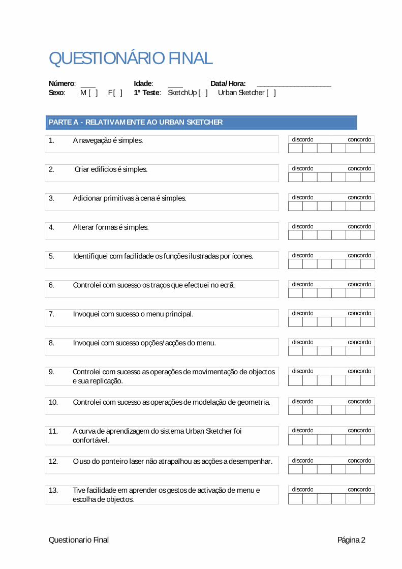
Questionario Final Página 2
QUESTIONÁRIO FINAL Número: ____ Idade: ____ Data/Hora: ____________________ Sexo: M [ ] F [ ] 1º Teste: SketchUp [ ] Urban Sketcher [ ]
PARTE A - RELATIVAMENTE AO URBAN SKETCHER
1. A navegação é simples. discordo concordo
2. Criar edifícios é simples. discordo concordo
3. Adicionar primitivas à cena é simples. discordo concordo
4. Alterar formas é simples. discordo concordo
5. Identifiquei com facilidade os funções ilustradas por ícones. discordo concordo
6. Controlei com sucesso os traços que efectuei no ecrã. discordo concordo
7. Invoquei com sucesso o menu principal. discordo concordo
8. Invoquei com sucesso opções/acções do menu. discordo concordo
9. Controlei com sucesso as operações de movimentação de objectos
e sua replicação. discordo concordo
10. Controlei com sucesso as operações de modelação de geometria. discordo concordo
11. A curva de aprendizagem do sistema Urban Sketcher foi
confortável. discordo concordo
12. O uso do ponteiro laser não atrapalhou as acções a desempenhar. discordo concordo
13. Tive facilidade em aprender os gestos de activação de menu e
escolha de objectos. discordo concordo

Questionário Final Página 3
PARTE B - COMPARANDO URBAN SKETCHER COM SKETCHUP
1. Considerou a experiência de controlar o sistema com o ponteiro laser, assim como o funcionamento dos menus e opções agradável?
Resposta:
2. Foi mais difícil utilizar o sistema Urban Sketcher que o SketchUp?
Quanta dessa dificuldade crê derivar do sistema em si?
Resposta:
3. Achou conveniente a liberdade de ter os menus posicionados livremente para invocar opções no
ecrã ou prefere um modelo com uma interface mais convencional?
Resposta:
4. Conseguiu adaptar-se ao conjunto de operações de modelação oferecidas pelo Urban Sketcher?
De quais sentiu mais falta e quais achou mais complicadas de aplicar?
Resposta:
5. Analisando os diversos modos de navegação disponibilizados pelos 2 sistemas, qual preferiu usar?
Resposta:

Questionário Final Página 4
Outras observações:
Muito obrigado pela sua participação!

Tarefas do Teste Final Página 1
TAREFAS DO TESTE FINAL
TAREFA A – NAVEGAÇÃO
Colocar-se frente à entrada principal do edifício residencial (porta vermelha).
Ler assinatura presente na estátua da rotunda.
TAREFA B – MODELAÇÃO
Criar as seguintes formas geométricas:
Figura 1 - forma 1
Figura 2 - forma 2
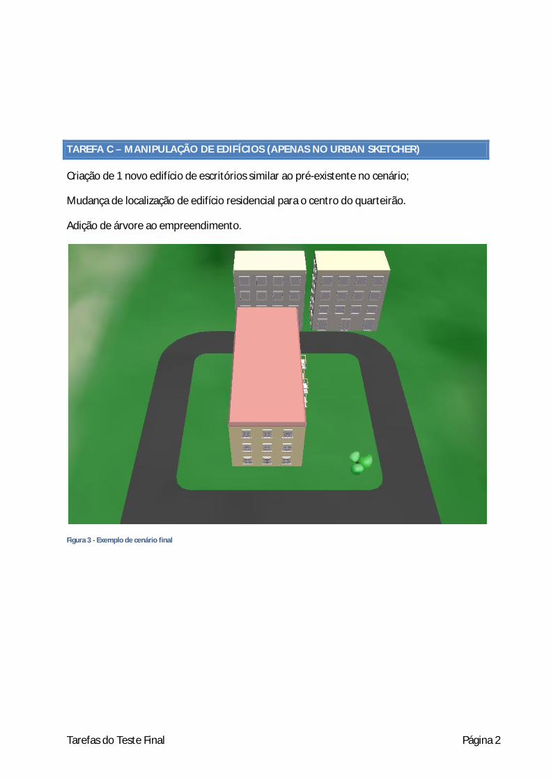
Tarefas do Teste Final Página 2
TAREFA C – MANIPULAÇÃO DE EDIFÍCIOS (APENAS NO URBAN SKETCHER)
Criação de 1 novo edifício de escritórios similar ao pré-existente no cenário;
Mudança de localização de edifício residencial para o centro do quarteirão.
Adição de árvore ao empreendimento.
Figura 3 - Exemplo de cenário final


C Appendix: Related Papers
65

GeoSculpt – edicao de geometria 3D baseada em tracos
Jose Pedro Dias Joaquim JorgeInstituto Superior Tecnico INESC-IDAv. Prof. Dr. Cavaco Silva R. Alves Redol, 9
2744-016 Porto Salvo 1000-029 [email protected] [email protected]
ResumoA criacao de conteudo tridimensional encontra-se frequentemente associada a uma interface com o utilizador comdezenas de botoes, atalhos de teclas e parametros numericos. Os ambientes de visualizacao de larga escala naotem tradicao de servir este proposito. Este artigo apresenta uma solucao que permite a um utilizador munidode um ponteiro laser convencional frente a um ecra de larga escala ou de um tablet PC com caneta elaboreoperacoes geometricas sobre um modelo tridimensional. Este modo de interaccao decorre no proprio ambientede visualizacao, sendo baseado em tracos e menus contextuais. O sistema determina as direccoes mais naturaisde aplicacao de operacoes(normal a face, aresta dentro da face vizinha, etc.). O utilizador escolhe entao osparametros da operacao com a execucao de um traco que desambigua direccao e distancia. O presente documentodescreve a interface disponibilizada, operacoes permitidas e representacao interna.
Palavras-Chavemanipulacao directa, modelacao tridimensional, interaccao por via de gestos.
1 Introducao
O proposito deste trabalho e o de permitir a utilizado-res a execucao de operacoes geometricas sobre modelostridimensionais. As operacoes devem ser fornecidas aoutilizador de forma contextual, no proprio ambiente devisualizacao, fornecendo um conjunto de restricoes direc-cionais de modo a auxilia-lo a obter o efeito desejado.
A aplicacao de uma operacao inicia-se com a seleccaoatraves de um traco de uma face ou aresta a afectar,o que despoleta o aparecimento de um menu contex-tual. O utilizador escolhe entao a operacao a aplicar,sendo esse mesmo traco interpretado para determinacaodos parametros da operacao.
O sistema foi implementado como funcionalidade doprototipo multimodal ImmiView presente no laboratorioLourenco Fernandes do IST Tagus Park [Araujo 05], per-mitindo a sua aplicacao em cenarios com tablet PCs ouecras de larga escala.
2 Interface com Utilizador
A escolha de face efectua-se desenhando exclusivamentesobre a face. A escolha de aresta efectua-se cruzando amesma, tendo inıcio numa das suas faces vizinhas e aca-bando na outra. A figura 2 ilustra este processo.
Uma vez escolhido o componente, um menu contextualsurge, permitindo a escolha de uma operacao a aplicar (verfigura 3).
Figura 1: monitor modelado no sistema
Figura 2: seleccao de aresta e de face
Figura 3: activacao de menu contextual de aresta
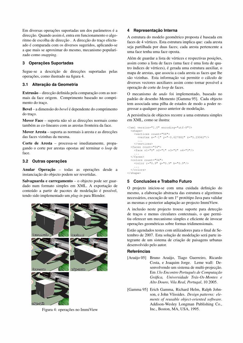
Em diversas operacoes suportadas um dos parametros e adireccao. Quando assim e, entra em funcionamento o algo-ritmo de escolha de direccao . A direccao do traco efectu-ado e comparada com os diversos sugeridos, aplicando-sea que mais se aproximar do mesmo, mecanismo populari-zado como snapping.
3 Operacoes Suportadas
Segue-se a descricao de direccoes suportadas pelasoperacoes, como ilustrado na figura 4.
3.1 Alteracao da Geometria
Extrusao – direccao definida pela comparacao com as nor-mais da face origem. Comprimento baseado no compri-mento do traco.
Bevel – a dimensao do bevel e dependente do comprimentodo traco.
Mover Face – suporta nao so as direccoes normais comotambem as co-lineares com as arestas fronteira da face.
Mover Aresta – suporta as normais a aresta e as direccoesdas faces vizinhas da mesma.
Corte de Aresta – processa-se imediatamente, propa-gando o corte por arestas opostas ate terminar o loop deface.
3.2 Outras operacoes
Anular Operacao – todas as operacoes desde ainstanciacao do objecto podem ser revertidas.
Salvaguarda e carregamento – o objecto pode ser guar-dado num formato simples em XML. A exportacao deconteudo a partir de pacotes de modelacao e possıvel,tendo sido implementado um plug-in para Blender.
Figura 4: operacoes no ImmiView
4 Representacao Interna
A estrutura do modelo geometrico proposta e baseada emfaces de 4 vertices. Esta estrutura implica que: cada arestaseja partilhada por duas faces; cada aresta pertencente auma face tenha uma face oposta.
Alem de guardar a lista de vertices e respectivas posicoes,assim como a lista de faces (uma face e uma lista de qua-tro ındices de vertices), e gerada uma estrutura auxiliar, omapa de arestas, que associa a cada aresta as faces que lhesao vizinhas. Esta informacao vai permitir o calculo dediversos vectores auxiliares assim como tornar possıvel aoperacao de corte de loop de faces.
O mecanismo de undo foi implementado, baseado nopadrao de desenho Memento [Gamma 95]. Cada objectotem associada uma pilha de estados de modo a poder re-gressar a qualquer passo anterior de modelacao.
A persistencia de objectos recorre a uma estrutura simplesem XML, como se ilustra:
<?xml version="1.0" encoding="utf-8"?><shape><vertices count="56">
<vertex x="-1" y="-0.627882" z="5.29942"/>...
</vertices><faces count="54"><face v1="0" v2="1" v3="2" v4="3"/>...
</faces><colors count="54"><color r="0.9" g="0.9" b="0.9"/>...
</colors></shape>
5 Conclusoes e Trabalho Futuro
O projecto iniciou-se com uma cuidada definicao domesmo, a elaboracao abstracta das estrutura e algoritmosnecessarios, execucao de um 1o prototipo Java para validaras mesmas e posterior adaptacao ao projecto ImmiView.
A inclusao neste projecto trouxe suporte para deteccaode tracos e menus circulares contextuais, o que permi-tiu oferecer um mecanismo simples e eficiente de invocaroperacoes geometricas sobre formas tridimensionais.
Estao agendados testes com utilizadores para o final de Se-tembro de 2007. Esta solucao de modelacao sera parte in-tegrante de um sistema de criacao de paisagens urbanasdesenvolvido pelo autor.
Referencias[Araujo 05] Bruno Araujo, Tiago Guerreiro, Ricardo
Costa, e Joaquim Jorge. Leme wall: De-senvolvendo um sistema de multi-projeccao.Em 13o Encontro Portugues de ComputacaoGrafica, Universidade Tras-Os-Montes eAlto Douro, Vila Real, Portugal, 10 2005.
[Gamma 95] Erich Gamma, Richard Helm, Ralph John-son, e John Vlissides. Design patterns: ele-ments of reusable object-oriented software.Addison-Wesley Longman Publishing Co.,Inc., Boston, MA, USA, 1995.

Utilizacao de Motion Tracking para Navegacao eManipulacao de Objectos frente a Ecra de Larga Escala
Jose Pedro Dias Jose Goncalves Joaquim JorgeInstituto Superior Tecnico INESC-IDAv. Prof. Dr. Cavaco Silva R. Alves Redol, 9
2744-016 Porto Salvo 1000-029 [email protected] [email protected] [email protected]
ResumoNavegacao em cenas tridimensionais em ambientes de visualizacao de larga escala constitui um desafio para arealizacao de interfaces simples, mas expressivas e faceis de aprender. Este artigo apresenta uma solucao baseadaem interfaces multimodais, combinando captura de movimento, gestos e fala que permite a utilizadores navegaremna primeira pessoa, com as maos livres num mundo virtual representado num ecra multi-projeccao de larga escala.Para tal utilizamos camaras de infravermelhos que seguem marcadores fixados ao corpo dos utilizadores. Osistema utiliza a metafora do Super-Homem para permitir voo controlado utilizando movimentos dos bracos. Demodo semelhante e possıvel manipular e transformar objectos. Este documento descreve os princıpios e algunsdetalhes da nossa abordagem, descrevendo testes efectuados com utilizadores e uma discussao dos resultados.
Palavras-Chavecaptura de movimentos, manipulacao directa, navegacao, manipulacao de objectos, interaccao por via de gestos.
1 Introducao
A navegacao numa cena tridimensional processa-se nor-malmente usando um computador de secretaria, com rato eteclado como dispositivos de entrada e monitor como dis-positivo de saıda. Foi desenvolvido no laboratorio Prof.Lourenco Fernandes[Araujo 05] um conjunto de modos deinteraccao que se tem provado eficazes para o efeito, re-correndo a equipamento de captura de movimentos e umecra de larga escala para navegar num ambiente virtual emanipular objectos na perspectiva da primeira pessoa.
Este trabalho pretende proporcionar uma interaccao maisdirecta para navegacao tridimensional, sem recurso a dis-positivos intrusivos. Recorre a comandos de voz para se-leccionar a accao a executar e a movimentos dos bracospara controlar o desenrolar da mesma.
2 Modos de interaccao
Segue-se a descricao dos diferentes modos de interaccaosuportados pela aplicacao.
2.1 Navegacao no espaco
A navegacao no espaco faz uso dos bracos estendidos (imi-tando o super-homem) para determinar a direccao e velo-cidade do voo.
O controlo da velocidade de voo e regulada pela distanciaentre maos: quanto mais afastadas estiverem as maos maislento e o deslocamento, ate a uma amplitude limite – cerca
de 90o – em que o utilizador para no ar; a velocidademaxima e atingida com as maos juntas (fig. 1a).
A direccao lateral do voo e afectada elevando um bracomais que o outro, sendo que quanto maior for a diferencade elevacao, maior a rotacao imprimida. Para rodar paradireita deve levantar-se o braco esquerdo e baixar o direito(fig. 1b); vice-versa para rodar para a esquerda.
A alteracao da altitude do voo efectua-se elevando ou bai-xando simultaneamente os bracos (fig. 1c).
(a) Speed (b) Yaw (c) Pitch
Figura 1: Modo Voar
2.2 Manipulacao de objectos seleccionados
Para mover um objecto deve estender-se o braco direito. Asua direccao determina a translaccao do objecto mapeadano plano horizontal do mundo (fig. 2).
Para rodar um objecto deve estender-se o braco direitoem direccao ao cenario e fazer um movimento circular noplano paralelo ao ecra imediatamente a frente do utiliza-dor(como se estivesse a limpar um vidro). O sentido darotacao do braco e mapeado directamente no sentido darotacao do objecto (fig. 3). O eixo de rotacao e previa-mente escolhido atraves do comando de voz que inicia o

modo.
Para alterar a escala do objecto seleccionado tem re-levancia a distancia entre maos. A posicao inicial dosbracos aquando a seleccao do modo escala serve de pontode partida para a alteracao da mesma. Daı em diante, paraaumentar a escala de um objecto deve afastar-se as maos epara o reduzir aproxima-las (fig. 4). A escala e restringidaa um eixo previamente escolhido atraves do comando devoz que inicia o modo.
Figura 2: Modo mover
Figura 3: Modo rodar
Figura 4: Modo escala
3 Configuracao Fısica
A captura de movimentos efectuou-se recorrendo a fixacaode marcadores reflectores nos bracos do utilizador e ainstalacao de um conjunto de 4 camaras com lampadas deinfra-vermelhos, cuja imagem e processada por um com-putador que identifica em cada imagem os marcadoresvisıveis no espaco-imagem, faz a computacao da posicaoespacial referente a cada marcador pelo cruzamento dosdados das 4 camaras e efectua uma etiquetagem dos mar-cadores segundo uma posicao inicial dos bracos.
Tivemos a nossa disposicao o Microsoft Speech API 5.1,versao american english. A captura de comandos de vozfoi efectuada com um microfone wireless da Microsoft,apos a comparacao do reconhecimento do mesmo face aum microfone fixo e um Bluetooth.
3.1 Gramatica
Foi projectada uma pequena gramatica que permitisse aactivacao dos diferentes modos multimodais:
Fly: begin flying , stop flyingDrag: begin drag, stop dragRotate:begin rotate ( X | Y | Z ) , stop rotateScale: begin scale ( X | Y | Z | Overall ) , stop scale
O reconhecedor mostrou-se algo limitado, tendo sido ne-cessario adaptar a gramatica a palavras nao ambıguas entresi ou que gerassem falsos positivos.
4 Testes com utilizadores
Em Julho de 2007 foram efectuados testes de usabilidadena cidade de Glasgow, na Escocia, no ambito do programaIMPROVE, em que o ImmiView se insere.
Participaram 10 utilizadores, estudantes de arquitectura earquitectos. Os mesmos foram distribuıdos em grupos de2, realizando cada um um conjunto de tarefas em separadoe uma tarefa colaborativa, estando um deles munido dosmarcadores.
Figura 5: utilizador em modo voo
5 Avaliacao e Discussao
A leitura dos marcadores mostrou-se problematica em in-divıduos de baixa estatura. Supomos que a origem estejanuma maior frequencia de oclusoes.
A necessidade do sistema de captura de movimentos terinıcio com uma posicao predefinida do utilizador e a poucarobustez do mesmo face a oclusoes dificulta a presenca deoutros indivıduos no espaco capturado.
Foi necessario alterar a gramatica de voz para desambiguaralguns comandos.
Os utilizadores apreciaram as funcionalidades fornecidas,nao se mostrando inibidos na sua aplicacao.
Os modos alternativos de navegacao e manipulacao aquidescritos mostram-se nao so viaveis como vantajosos facea interfaces WIMP. A navegacao mostrou-se particular-mente poderosa, podendo o utilizador controlar de formacontınua diversos parametros do voo recorrendo apenas amovimentacao dos seus bracos para o fazer.
6 Conclusoes
Neste artigo apresentamos uma interface multimodal sim-ples mas poderosa para suportar as accoes mais comunsde manipulacao e visualizacao tridimensional em ecras delarga escala, combinando captura de movimentos, fala egestos numa interface natural.
Testes realizados com utilizadores permitiram verificar aeficacia e virtudes da nossa abordagem maos-livres quesubstitui com vantagem tecnicas mais convencionais.
Referencias
[Araujo 05] Bruno Araujo, Tiago Guerreiro, RicardoCosta, e Joaquim Jorge. Leme wall: De-senvolvendo um sistema de multi-projeccao.Em 13o Encontro Portugues de ComputacaoGrafica, Universidade Tras-Os-Montes e AltoDouro, Vila Real, Portugal, 10 2005.

Interface Caligrafica para Ecras de Larga Escala
Ricardo Jota Bruno Araujo Luıs Bruno Jose Dias Joao M. Pereira Joaquim A. JorgeGrupo de Interfaces Multimodais Inteligentes
DEIC / INESC-ID / IST - Instituto Superior Tecnicohttp://immi.inesc-id.pt
ResumoA utilizacao de ecras de larga escala em sistemas de visualizacao esta a tornar-se comum. No entanto, poucassolucoes de interaccao tiram realmente partido da area de visualizacao e do espaco de trabalho. Na maioriados casos, o seu uso limita-se a visualizacao de modelos 3D em que o utilizador e espectador e, recorrendo adispositivos tradicionais como o rato e o teclado, um operador navega pelo modelo. Neste trabalho propomos umanova abordagem de interaccao que utiliza apontadores laser e que permite a um ou mais utilizadores interagirde forma natural com um ecra de larga escala. Transpondo o conceito de interface caligrafica de aplicacoesdesktop para o ecra de larga escala, oferecemos um conjunto de metaforas de interaccao baseadas em tracos einspiradas na metafora do lapis e papel. Sobre estes conceitos, apresentamos uma nova interface com o utilizador,baseada em menu circulares com suporte a multi-utilizadores. Apresentamos o prototipo ImmiView que oferece asfuncionalidades de navegacao, modelacao simples e criacao de anotacoes para a area da arquitectura. Finalmente,apresentamos as conclusoes baseadas em testes efectuados sobre o prototipo.
Palavras-ChaveEcra de larga escala, Interface Caligrafica, Interface com o Utilizador
1 Introducao
Os ecras de larga escala definem-se pela capacidade deapresentar uma grande quantidade de informacao devidoao uso de uma resolucao bastante elevada, mas tambemdevido a dimensao fısica da projeccao definida tanto empixeis como, para uma referencia mais compreensıvel, emmetros. De uma forma geral, a dimensao fısica destecenario permite ao utilizador uma maior liberdade de mo-vimento e um maior espaco de trabalho, comparado como tradicional cenario de desktop. Como tal, a interaccaobaseada em dispositivos de entrada, tais como o tecladoe o rato, nao e ideal porque limita a liberdade fısica doutilizador, uma vez que nao tira partido, de uma forma na-tural, do espaco de interaccao que o cenario oferece. Estalimitacao e partilhada pela maioria das interfaces actual-mente disponıveis, em cenarios de larga escala ou cenariosdesktop. Propomos neste trabalho apresentar uma tecnicade interaccao mais adequada aos ecras de larga escala, quetira partido da dimensao da area de visualizacao. A nossatecnica recorre a ponteiros laser para permitir que variosutilizadores interajam, simultaneamente, com um ecra delarga escala, de uma forma mais natural, seguindo umametafora semelhante ao papel e lapis. Desta forma ofe-recemos uma interface caligrafica para ecras de larga es-cala que permite uma maior liberdade, em comparacaocom as abordagens para desktop, dado que a nossa tecnicanao obriga o utilizador a interagir a partir de um local pre-definido, nem a utilizar artefactos que impecam a sua mo-
bilidade. Por outro lado, apresentamos uma nova inter-face com o utilizador e metaforas de interaccao que tentamsuperar a expressividade limitada do ponteiro laser. Umexemplo da expressividade limitada do laser verifica-se nonumero de estados possıveis de funcionamento do laser emcomparacao com os do rato. No caso do laser, pode es-tar ligado ou desligado. No caso do rato com um unicobotao os estados sao: desligado, ligado sem botao acti-vado ou ligado com botao activado. Baseado nas carac-terısticas dos ponteiros laser e nas suas limitacoes, desen-volvemos metaforas de interaccao que abrangem conceitosde seleccao de objectos ou de escolha de opcoes, e con-ceitos mais complexos como a criacao de menus globaisou de menus de contexto, que tirem partido do aumentode area de visualizacao e de interaccao oferecido pelosecras de larga escala. Os conceitos propostos sao adapta-dos a cenarios colaborativos multi-utilizador. Em cenariosmulti-utilizador a area de interaccao e aproveitada de me-lhor forma, ao permitir que varios utilizadores interajamcom o ecra simultaneamente. Este sistema de interaccaosuporta, de forma robusta, a interaccao de dois ou maisutilizadores, sem que ocorram interferencias de interaccaode um utilizador causadas por outro utilizador.
O artigo apresenta uma nova interface caligrafica cons-tituıda por mecanismos de interaccao baseada em Tracos,que permitem activar opcoes e seleccionar elementos natu-ralmente. Iniciamos o artigo com uma breve introducao eapresentamos o trabalho relacionado na seccao 2. A seccao

3 apresenta os conceitos base nos quais a interface se ba-seia. Na seccao 4 apresentamos a interface com o utiliza-dor descrevendo os menus desenvolvidos para os ecras delarga escala e o seu uso por varios utilizadores recorrendoa apontadores laser. De seguida, apresentamos as tecnicasutilizadas, por forma a viabilizar o uso do apontador la-ser como dispositivo de entrada, providenciando mecanis-mos para o suporte de varios apontadores. Como exemplodas tecnicas apresentadas e descrito o uso da interface ca-ligrafica no ambito do prototipo ImmiView que oferece ta-refas de navegacao, modelacao simples e anotacao em am-bientes tridimensionais e reportamos os comentarios obti-dos nos primeiros testes com utilizadores. Para finalizarsao apresentadas as conclusoes e o trabalho futuro a serrealizado no ambito da interaccao proposta.
2 Trabalho Relacionado
Durante a decada de 1990, varias interfaces caligraficasforam desenvolvidas tirando partido de dispositivos deentrada tais como canetas digitalizadoras ou computado-res TabletPCs para oferecer uma alternativa mais ade-quada a tarefas de modelacao 3D. Sistemas como oSketch[Zeleznik 96] e Teddy [Igarashi 99] propuseram in-terfaces que, em vez de usar o conceito WIMP, utiliza-vam Tracos, esbocos ou o reconhecimento de sımbolospara aceder a varios operadores de modelacao 3D. Aaplicacao Sketch permitia desenhar em vistas tridimen-sionais usando uma sintaxe baseada em sımbolos 2D efoi seguida por varias sistemas de modelacao tais como oGides[Pereira 03], explorando mecanismos para auxiliar ainterpretacao de esbocos e o SmartPaper[Shesh 04] com-binando algoritmos de reconstrucao 3D sobre esbocos. Al-ternativamente ao uso de comandos caligraficos, o sistemaTeddy permitia construir formas geometricas, simples-mente desenhado o contorno via um unico Traco. Variostrabalhos [dA03, Nealen 05] tentaram enriquecem a abor-dagem de forma a oferecer operadores mais complexos enaturais tentando imitar cada vez mais a metafora do pa-pel e lapis. Apitz e Guimbretiere[Apitz 04] apresentamuma interface baseada em Tracos e demonstraram-na so-bre uma aplicacao de desenho. Esta interface baseia-se emdesenhar Tracos para activar elementos de interface comomudanca de cor ou seleccao de pincel.
Jiang et al.apresentam uma solucao para interaccao comecras de larga escala. Ao utilizar um rato sem fios aco-plado a uma camara USB e possıvel detectar a posicao dorato, e consequentemente a do seu ponteiro, que e repre-sentado por um cırculo vermelho no ecra. Determina-se,assim, o movimento desejado pelo utilizador calculandoa posicao do cırculo relativo ao centro da imagem captu-rada pela camara e movendo o cırculo nesta direccao. Caoe Balakrishnan[Cao 03] apresentam uma interface baseadana captura de uma varinha magica para controlar um ecrade larga escala. Os autores optaram por apresentar umaaplicacao onde a interface esta reduzida ao mınimo, uti-lizando o conceito de Widgets sempre que e necessarioapresentar funcionalidade ao utilizador. Com o conceitode widgets os autores apresentam uma implementacao do
menu circular adaptado a interaccao por varinha magica.
Jacoby e Ellis [Jacoby 92] utilizaram menus 2D sobre ge-ografia 3D, para adaptar o sistema de menus ao contextode realidade virtual. Esta solucao e considerada limitada,devido as diferencas de interaccao latentes em ambientes3D. Outro caminho desenvolvido e a utilizacao de menuscirculares, ja utilizados em varias aplicacoes 2D, e quefacilita o acesso as opcoes em ambiente 3D em relacaoaos menus tradicionais(Ver [Hopkins 91] e [Callahan 88]).O sistema Holosketch tambem utiliza uma abordagem se-melhante ([Deering 95]). Neste trabalho Deer apresentatodos os comandos disponıveis na forma de objectos eıcones 3D, organizados de forma circular. O projectoSmart Sketches apresenta outro exemplo de menus circu-lares [Santos 04]. Todos estes trabalhos desenvolveram di-ferentes tipos de solucoes para menus em ecras de largaescala e alguns apresentam solucoes de menus circula-res. Todas as abordagens anteriores baseiam-se no clickcomo metafora de activacao. Embora nao desenvolvidopara ecras de larga escala, Guimbretiere[Guimbretiere 00],apresenta uma solucao para menus circulares onde e utili-zado um Traco como mecanismo de seleccao.
Existe varia literatura relacionada com a utilizacao deLasers como dispositivo de entrada. Lapointe e Godin[Lapointe 05] apresentam um sistema para deteccao de La-ser em cenarios de retro-projeccao. Embora muito seme-lhante a solucao apresentada neste artigo, nao contemplavarias camaras para deteccao de lasers pelo que a area decaptura e limitada. Davids e Chen [Davis 02] apresentamuma nova versao do algoritmo apresentado por Godin, queja contempla varias camaras e, devido a esse facto, Chendescreve a utilizacao de um filtro de kalman para empa-relhamento de eventos. Oh e Stuerzlinger[Oh 02] apre-sentam um estudo que valida o Laser como uma opcaoadequada a cenarios de ecras de larga escala. Oh apre-senta tambem uma solucao para a identificacao de dife-rentes lasers em simultaneo. Esta solucao baseia-se emHardware especıfico para identificar que laser esta ligado.Consideramos que esta solucao e demasiado pesada paraser considerada viavel. Myers et al.[Myers 02] apresentaum estudo onde compara a eficacia de varios tipos de la-ser, a uma certa distancia do ecra. Myers conclui que astecnicas actuais nao funcionam com o laser devido a faltade precisao dos ponteiros Laser. Olsen [Olsen 01] tentacolmatar essa falta de precisao utilizando tecnicas, comoo Dwelling, que pretendem adaptar o conceito de janela,ıcones, rato e apontar (i.e WIMP : Windows, Icon, Mouseand Pointing) a utilizacao do laser. Embora concordemoscom Myers, consideramos que o trabalho de Olsen tentaadaptar-se a uma realidade que nao retira o maximo par-tido dos ecras de larga escala.
3 Abordagem de Interaccao
A maioria das interfaces para desktop foram desenhadaspara dispositivos como o teclado e o rato, baseando-seprincipalmente no conceito de point & click. Este conceitoutiliza o espaco de interaccao de forma discreta e pontual,e restringe o uso da informacao contınua na manipulacao

Figura 1. Exemplos de Traco. De topoesquerda, na direccao dos ponteiros dorelogio: Curva Fechada, Risco, CurvaAberta, Sımbolo, Gesto de Triangulo e exem-plo de caminho.
Figura 2. Traco representado a amarelo tra-cejado na aplicacao IMMIView
directa de elementos. A nossa abordagem de interaccao re-pousa, exclusivamente, no conceito de Traco para interagircom o ecra de larga escala, permitindo o uso de interaccaocontınua na interface do utilizador.
3.1 Conceito Traco
O conceito de Traco e o elemento basico da nossa inter-face caligrafica. Todas as metaforas de interaccao que pro-pomos para interagir com os ecras de larga escala assen-tam nesse conceito. De forma simples, um Traco e umasequencia de pontos, obtido do dispositivo de entrada epode representar um risco ou linha, uma curva aberta ou fe-chada. No entanto, a nıvel da interaccao, um unico Tracopode ser interpretado como um caminho sobre a area deinteraccao, um gesto, ou um sımbolo que pode ser umaforma simples, um esboco mais complexo ou um elementoescrito. Na Figura 1 encontram-se exemplificadas variasinterpretacoes possıveis de Tracos. Desta forma permiti-mos ao utilizador interagir de forma contınua com a areade interaccao e nao de forma pontual.
Por outro lado, o Traco torna-se para o utilizador arepresentacao da sua interaccao e permite-lhe identificar asua localizacao na area de interaccao. Utilizar dispositivoscomo os apontadores laser, permite-nos nao so interagir emcontacto fısico com o ecra, de forma semelhante a um ecrasensıvel ao toque, como na Figura 2, mas tambem intera-gir a distancia, oferecendo maior liberdade ao utilizador etornando acessıvel qualquer parte do ecra de larga escala.
Elemento
Figura 3. Na esquerda apresenta-se umexemplo de activacao de um elemento de in-terface por Mecanismo de Riscar. A direitaapresenta-se um exemplo da seleccao como Mecanismo de Laco
3.2 Mecanismo de Riscar
O elemento mais basico que pode ser representado porum Traco e uma linha constituıda por dois pontos (riscosimples). Uma das principais metaforas de interaccao,recorrendo a Tracos, e riscar elementos sobre a area deinteraccao tal como riscamos ou sublinhamos palavrasnuma folha de papel. Na nossa abordagem de interaccao,o risco e utilizado como forma natural de activar os ele-mentos da interface com o utilizador. Desta forma, ele-mentos com uma area de visibilidade diminuta, podem serseleccionados e activados tais como as opcoes de menu,de forma semelhante ao acto de riscar um elemento deuma lista de palavras no papel. O mecanismo permite asubstituicao do conceito de click pelo de riscar, que nocenario de interaccao com um ecra de grande dimensao,pode ser efectuado perto ou longe. Por outro lado, umTraco pode riscar ou activar varios elementos, oferecendouma forma contınua de interaccao dado que um Traco podeser visto como um caminho ou uma sequencia de riscos.
3.3 Mecanismo de Laco
Seguindo a metafora do lapis e do papel, propomos o usodo Laco (tipo de Traco), para seleccionar de forma naturalobjectos presentes na interface do utilizador. Este recursode interaccao e vulgarmente utilizado em qualquer editorde imagem. O Laco permite seleccionar todos os objectoslocalizados no seu interior, tal como fazemos no papel. Poroposicao ao mecanismo de riscar, o Laco e utilizado ex-clusivamente para seleccionar. Atraves deste mecanismo,e oferecida ao utilizador uma forma simples de seleccionarelementos que lhe sao apresentados no ecra, permitindoseleccionar um ou mais elementos com um unico Traco,independentemente da distancia a que o utilizador utilizao ponteiro laser. A Figura 3 descreve a diferenca entre osmecanismos de riscar e de Laco.
3.4 Mecanismo de Gesto
O ultimo mecanismo descrito e o mecanismo de gesto.O gesto e uma interpretacao possıvel do Traco que podeir do simples movimento ao reconhecimento de um dadosımbolo efectuado pelo utilizador. Desta forma os gestos

podem ser utilizados como atalhos para aceder a funciona-lidades. Este metodo ja esta disponıvel em varias interfa-ces para desktop, nas quais permite-se associar o reconhe-cimento de um dado sımbolo a uma dada funcionalidade.Os gestos escolhidos devem ser sımbolos simples de formaa facilitar a sua memorizacao.
4 Interface de Utilizador
Tirando partido dos mecanismos descritos anteriormente,desenvolvemos uma interface que permite, aos utilizado-res, interagir com varios tipos de cenarios, nomeadamentecom um ecra de larga escala. A interface e constituıda poropcoes, ou um conjunto de opcoes (menus), apresentadasnuma tela bidimensional que expoe a funcionalidade daaplicacao, e que pode ser complementada com o uso deoutras modalidades tais como a voz. A nossa interface per-mite as seguintes accoes: riscar as opcoes de menus paraactivar accoes, circunscrever objectos 3D com um Lacopara selecciona-los e desenhar um triangulo (gesto) paraaccionar o menu principal. Por outro lado, tiramos partidodo conhecimento dos objectos seleccionados, por forma aapresentar menus contextuais e a expor a funcionalidaderelacionada com o tipo de objecto seleccionado.
4.1 Opcoes
Desenvolvemos uma solucao de escolha de opcoes quesuporta tanto o cenario de interaccao via caneta com Ta-bletPC, como o apontador laser sobre o ecra de larga es-cala. Em ambos os cenarios ocorre falta de informacaoface ao cenario normal do rato em computador de se-cretaria: o sistema nao tem conhecimento da area paraonde o utilizador esta a apontar ate que o mesmo pressi-one a caneta sobre o TabletPC ou o laser sobre a tela. Afalta desta informacao torna as interfaces de apontar e cli-car pouco adequadas - e muito difıcil atingir alvos peque-nos com a caneta, mais ainda no caso do laser uma vez queo utilizador falha frequentemente a area onde quer clicardada a inexistencia de feedback visual antes de pressionaro botao do apontador.
Figura 4. Gates: textual e com ıcone
A solucao encontrada vai no sentido do trabalho executadopor Apitz e Guimbretiere[Apitz 04]. Os autores tambempropoem activar as opcoes do sistema, riscando-as. Nestetrabalho apresentam um prototipo de um programa de de-senho baseado neste conceito. Cada opcao do sistema eentao uma area com um texto ou um ıcone, contendo noslimites verticais, ao centro, duas pequenas marcas a suge-rir os limites da linha de activacao da opcao, como ilus-trado na Figura 4. O utilizador encontra-se dentro da gate
quando entra nos limites da caixa que a engloba. A opcaoe activada quando o Traco cruza a linha que divide a gateverticalmente ao meio (Figura 5). Foi tomada a decisaode nao misturar texto e ıcones na representacao da gatepara melhorar a indentificacao da accao representada pelagate. Os ıcones usados nas opcoes do sistema tem assimque ser suficientemente explıcitos, de modo a que o utili-zador reconheca a funcionalidade associada.
Figura 5. Traco do utilizador e estado corres-pondente da gate
Para auxiliar os utilizadores inexperientes no sistema, foiimplementado um mecanismo de tooltips. Trata-se de umapequena caixa de texto com a descricao da funcionalidadeassociada a opcao textual. A mesma surge quando o Tracoentra na area da gate, e fica visıvel ate que o mesmo a aban-done. O texto associado a cada tooltip pode ser utilizadopara invocar os comandos de fala, que e uma outra formaalternativa de o utilizador escolher as opcoes de controlodo sistema. A presenca das tooltips permite que a apren-dizagem dos comandos de fala, seja mais facil, evitando asua memorizacao e potenciando a sua lembranca.
4.2 Menus
A interface proposta permite aos seus utilizadores activardiferentes funcionalidades do sistema atraves do uso demenus globais ou de menus contextuais. Por outro lado, foiadicionado o conceito de menus laterais, que permite au-mentar a expressividade dos menus globais e contextuais.Toda a interaccao parte do principio que os mecanismospreviamente descritos estao disponıveis. O menu principalpode ser aberto atraves do desenho de um triangulo (me-canismo de gesto). Este menu e composto por um con-junto de opcoes que permitem aceder aos menus de se-gundo nıvel. O objectivo do menu principal e apresentarum ponto de partida que separe, de forma clara, as variasfuncionalidades existentes no sistema. Os menus de se-gundo nıvel sao compostos por um conjunto de opcoesque permitem activar funcionalidades especıficas. Sempreque um menu de segundo nıvel e activado, o menu prin-cipal que lhe deu origem e fechado. Todos os menus, aexcepcao do menu principal, tem associados tres opcoesde manipulacao: ”fechar”, ”mover”e ”abrir o menu prin-cipal”. O menu principal so tem associado as opcoes ”fe-char”e ”mover”. Optou-se por dividir as opcoes de con-trolo por dois motivos: melhorar a navegacao entre gruposde funcionalidades (nao apresentando demasiadas opcoesao utilizador de uma unica vez); e porque, desta forma, epossıvel a um ou mais utilizadores abrir dois ou mais me-nus e mantendo-os abertos. E possıvel ao utilizador manter

Figura 6. Exemplo de menu principal (es-querda) e de um menu de segundo nıvel comas varias areas de interaccao (direita)
abertos em diferentes locais da interface varios menus, quepermitem realizar diferentes tarefas.
A localizacao dos menus tambem foi alvo de estudo. Emvez de existir permanentemente um menu aberto, na inter-face, que permitisse ao utilizador activar as suas operacoes,decidiu-se que os menus seriam abertos na posicao esco-lhida do utilizador. Para melhor posicionar os menus faceao utilizador, tendo em conta a dimensao da tela, optou-se por apresentar o menu principal na posicao onde o uti-lizador desenha o triangulo. Inicialmente os utilizadoresactivam os menus em locais pouco desejados, mas os tes-tes indicam que eles rapidamente criam os menus direc-tamente nos locais que desejam. Por outro lado, a par-tir do momento em que um utilizador abre o menu prin-cipal numa determinada posicao, consequentes menus desegundo nıvel serao abertos nessa posicao. Esta definicaopretende atribuir um espaco de trabalho ao utilizador, queesteja perto do seu posicionamento fısico, e que lhe per-mita de forma mais rapida e eficaz aceder as funciona-lidades pretendidas. No caso da interface ser utilizadade forma colaborativa por dois utilizadores, cada um de-les podera ter o seu espaco de trabalho, correspondendoa localizacao dos menus que abriram. Os menus circula-res propostos tem uma representacao grafica circular e saocompostos por duas circunferencias concentricas. Na su-perfıcie da coroa circular resultante estao as opcoes dosmenus. Estas opcoes estao inseridas dentro de circun-ferencias e seguem as definicoes explicitadas no capıtuloanterior. A escolha desta representacao circular permiteque o utilizador tenha uma maior acessibilidade as opcoesdos menus atraves do uso do laser e nao concentra a suamancha grafica numa so zona, o que poderia ocultar maisdetalhes da interface. O desenho dos menus foi baseadonum conjunto de princıpios, descritos na literatura, e quepretendem assegurar uma correcta interaccao com o utili-zador. As principais opcoes tomadas sao as seguintes:
• A sua representacao circular e semi-transparente (fazuso de um gradiente de cor) o que torna o sistemamenos intrusivo para o utilizador, minimizando aocultacao de informacao da interface.
• O numero de opcoes por menu deve ser o mais redu-zido possıvel por forma a tornar mais rapida e maisfacil a sua escolha por parte do utilizador. Nos nossostestes, o numero maximo de opcoes que utilizamosfoi de oito.
• Cada tipo de menu deve possuir uma cor diferente,que permita ao utilizador identificar rapidamente ocontexto de funcionalidades que lhe esta associado.Para reforcar a identidade do menu, existe uma eti-queta associada ao mesmo com o seu tıtulo.
• O sistema hierarquico de menus pode ter no maximotres nıveis, de forma a que o utilizador nao perca anocao da sua sequencia de escolhas.
4.3 Menus Laterais
De forma a nao aprofundar em demasia a navegacao dosmenus, o numero maximo de nıveis necessario para na-vegar entre grupos de opcoes e de tres. O primeiro nıvele identificado como o menu principal, o segundo nıvel eidentificado pelos menus de funcionalidade. O terceironıvel foi implementado utilizando menus laterais que estaoassociados aos respectivos menus de segundo nıvel. A de-cisao de manter abertos os menus de segundo nıvel, emconjunto com os seus menus laterais, deveu-se ao facto deconsiderarmos vantajoso que os menus de segundo nıvel,que representam funcionalidade, so sejam fechados porordem directa do utilizador (ao inves do primeiro nıvel).Os menus laterais (visıveis no lado esquerdo dos menusdas Figuras 10 e 12) resolvem dois problemas : permi-tem apresentar listas de opcoes agrupadas, reduzindo as-sim o numero de opcoes por menu de nıvel dois e per-mitem seleccionar o modo presente no menu de segundonıvel. Um menu de segundo nıvel pode ser constituıdo porvarios modos, cada qual permitindo efectuar diferentes ti-pos de accoes. Por exemplo, no nosso sistema, um menu detransformacao geometrica pode ter os modos: translacao,rotacao e escala, cujas opcoes de acesso estao num menulateral. Quando um utilizador escolhe um dado modo, to-das as opcoes presentes na coroa circular do menu saosubstituıdas, daı terem-se disponibilizando estas opcoesfora do menu. Outro efeito desta solucao e que todas as
Figura 7. Exemplo de um menu lateral, alter-nativo a solucao escolhida.

accoes que afectam o menu em si (mover, fechar, entreoutros) podem concentrar-se fora do menu, posicionando-se no topo direito da coroa circular (ver Figura 7). Em-bora a maioria dos nossos menus utilizem menus laterais,foi implementada uma solucao alternativa. Esta solucaoassemelha-se a expansao de opcoes comum em menus nor-malmente utilizados aplicada a nossa versao de menus cir-culares. Ao activar uma opcao e expandida uma seccao queapresenta novas opcoes. Esta solucao alternativa e ilus-trada na Figura 7, onde se pode ver o menu lateral expan-dido a esquerda do menu circular.
4.4 Menus Contextuais
Tal como foi referido anteriormente, propomos dois tiposde menus: globais e contextuais. Os primeiros, nos quaisesta incluıdo o menu principal, permitem a realizacaode determinados grupos de tarefas no sistema, como porexemplo a navegacao num cenario tridimensional. Os me-nus sao abertos usando um sımbolo (ex: triangulo) ou porfala, e surgem inicialmente junto ao Traco que os gerou,podendo no entanto ser arrastados pelo utilizador para ou-tra zona do ecra. Os menus contextuais estao associados aoperacoes a serem realizadas sobre objectos previamenteseleccionados pelo utilizador. Por exemplo, no caso deuso de um ambiente virtual, apos seleccionar um cubo,e aberto um menu contextual com as opcoes que permi-tem activar operacoes de transformacoes geometricas so-bre esse objecto. Estes menus dispensam a opcao de re-gresso ao menu principal ja que estao intimamente ligadoscom o objecto seleccionado. A razao que nos levou a di-vidir os menus em globais e de contexto prende-se com onumero de operacoes especıficas que podem ser realizadassobre determinados tipos de objectos. Accoes como apa-gar, mover ou duplicar um elemento requerem que ele sejapreviamente seleccionado. Uma vez que a seleccao e exe-cutada atraves de um mecanismo de Laco, e que todas asoperacoes sao realizadas a partir de menus, optou-se porunir ambos os conceitos e apresentar os menus de contexto(com as opcoes disponıveis para manipular esse objecto)sempre que um objecto e seleccionado. Esta decisao per-mite reduzir o numero de opcoes em cada menu sem des-cuidar a expressividade da interface.
5 Dispositivo de Entrada
Para satisfazer as metaforas definidas na seccao 3 foramdefinidas quatro caracterısticas que necessitam de ser sa-tisfeitas: rapidez, robustez, leveza e colaboracao. Parauma interaccao fluida, o dispositivo deve ser rapido e ro-busto. Para os mecanismos de Laco e de Gesto e im-portante que o retorno apresentado seja o mais imediatopossıvel. Deve ser robusto de forma a permitir que os ges-tos sejam melhor reconhecidos. Falhas nos dispositivos deentrada, embora nao impecam a interaccao, reduzem seri-amente o reconhecimento de gestos. Tendo em atencao aliberdade de movimentos presente em cenario de ecra delarga escala, um dispositivo pesado torna-se proibitivo. Deforma a permitir que o utilizador tenha liberdade de movi-mento e nao se sinta cansado por uma sessao de interaccaoprolongada, o dispositivo de entrada deve ser o mais leve
Figura 8. Algoritmo de captura do PonteiroLaser: Captura, Filtragem, Aplicacao
possıvel. Por fim, e porque o cenario oferece uma grandearea de interaccao, qualquer dispositivo deve ter em contaa interaccao colaborativa, onde dois ou mais utilizadoresinteragem simultaneamente com o ecra.
5.1 Dispositivo Laser
Tendo em conta as caracterısticas definidas optou-se porutilizar ponteiros laser como dispositivos de entrada. Oconceito da utilizacao de ponteiro laser baseia-se nametafora do Quadro Branco e na familiaridade ja existente,na maioria das pessoas, com ponteiros laser. Este con-ceito utiliza a incidencia do laser no ecra para desenharos Tracos. A solucao apresentada e leve, os ponteiros utili-zados pesam menos de 20 gramas; robusta, o sinal do lasere constante e facilmente detectavel atraves de sistemas devisao por computador; rapida - cada ciclo de captura de-mora 60 milesimos de segundo e permite a colaboracaoatraves da captura de varios ponteiros simultaneamente.
5.2 Algoritmo de Captura
O Laser e capturado utilizando um sistema de processa-mento de imagem. E utilizada uma camara sensıvel a in-fravermelhos e, para reduzir o ruıdo da imagem e aumentaro sinal de infravermelho, e utilizado um filtro que so per-mite a passagem de luz na gama dos infravermelhos. Osinal recebido pela camara e uma imagem em tons de cin-zento que representa a intensidade do infravermelho. Aposprocessamento da imagem, e possıvel filtrar os pixeis maisintensos onde se considera existir um laser. O resultadoda filtragem apresenta uma ou mais regioes de incidenciade laser. A posicao do laser e, de seguida, enviada para aaplicacao que traduz do espaco de coordenadas da camarapara o espaco de coordenadas da aplicacao. A Figura 8apresenta o resultado dos tres passos do algoritmo.
5.3 Filtro de Kalman
Para efectuar uma conversao entre as coordenadas de umaunica camara e as coordenadas de aplicacao basta encon-trar uma homografia que defina a conversao desejada. Noentanto, ainda nao e possıvel cobrir um ecra de larga escalacom quatro por tres metros com uma unica camara. Serianecessario ter uma resolucao bastante elevada e posicionara camara a uma distancia consideravel e num local ondeas oclusoes fossem mınimas. No caso do ecra de larga es-cala utilizado, existem limitacoes de espaco que proibiamtal solucao e optou-se por utilizar varias camaras a cobrirpartes diferentes do ecra, implementando um sistema quepermitisse identificar o ponteiro laser, mesmo quando estepercorre varias camaras.

Traços Activos Eventos de Entrada
Novo Evento
Sistema de Filtragem Kalman
Eventos Previstos
Evento Previsto Emparelhamento
Traço Terminado
Continuação de Traço
NovoTraço
Figura 9. Sistema de emparelhamento deeventos
O filtro de Kalman e um metodo de estimacao estocasticaque combina modelos determinısticos e estocasticos demodo a obter estimativas optimas de variaveis de estadode sistemas lineares[Welch 06]. A aplicacao do filtro deKalman a este problema permite estimar a posicao do la-ser. Desta forma, as camaras funcionam como clientes quesabem identificar posicoes laser e converter, recorrendo auma homografia, entre o seu espaco de coordenadas e oespaco da aplicacao. Estes clientes falam com um servidor,responsavel por recolher informacao de todas a camaras etraduzir isso em eventos de entrada coerentes. A Figura 9ilustra o processo efectuado por parte do servidor.
Ao aplicar a previsao do filtro de Kalman, e possıvel em-parelhar eventos de camaras diferentes para o mesmo pon-teiro. O emparelhamento permite identificar quando e quese inicia, mantem ou termina um Traco. Esta solucao temcomo vantagem uma melhor resolucao, devido ao numerode camaras, mas tambem oferece suporte a interaccao cola-borativa. Atraves da utilizacao de varios filtros, e possıveldeterminar o estado de cada Traco, como e apresentado naFigura 9. Caso so exista um evento previsto sem corres-pondencia real e considerado que o Traco foi terminado,ou seja, o laser foi desligado. Caso exista um evento realsem previsao associada, e iniciado um novo Traco tendocomo base este primeiro evento. Caso haja um emparelha-mento entre um evento previsto e um evento real o filtro deKalman correspondente ao evento previsto e actualizado ee considerado que o Traco existente mantem-se activo. Acada Traco detectado e associado um identificador unicoque permite as aplicacoes identificarem que eventos per-tencem a que Tracos.
6 Suporte a Multi-Utilizador
Uma vez desenvolvido um dispositivo de entrada que dis-ponibilize eventos de varias fontes em simultaneo, torna-se necessario processar os eventos de forma a que eventosde fontes diferentes nao entrem em conflito ou confundamo utilizador. Para tal, no ambito da interface apresentadaforam desenvolvidos duas solucoes que tem em vista o su-porte a interaccao colaborativa.
6.1 Cor do Traco Aleatoria
Para melhor representar varios Tracos em simultaneooptou-se por representar cada Traco com uma cor dife-
rente, escolhido de um sub-conjunto de cores identificadascomo de alta visibilidade. Desta forma, cada utilizador re-conhece a cor gerada pelo seu Traco e permite identificarque accoes foram directamente activadas por ele. A alea-toriedade da cor tambem permite reconhecer falhas no re-conhecimento contınuo do Traco, o que e bastante impor-tante no Mecanismo de Gestos uma vez que e necessarioum gesto contınuo para o reconhecimento de um gesto.
6.2 Pertenca
Na Interaccao colaborativa, caso os utilizadores estejambastante perto um do outro, algumas accoes podem ser ac-tivadas inadvertidamente. Embora alguns estudos[Tse 04],sugiram que, por norma, os utilizadores interagem emlocalizacoes separadas, surgem, por vezes, situacoes ondeum utilizador activa um menu e, devido a proximidade dainteraccao, outro utilizador activa uma opcao desse mesmomenu.
Como solucao foi criado o conceito de pertenca. Sempreque um Traco intersecta um elemento da interface e cri-ada uma relacao de Pertenca entre o Traco e o elementoda interface. A relacao de Pertenca cria uma associacaoum-para-um entre o Traco e elemento da interface. Aassociacao garante que o elemento da interface so recebeeventos proveniente daquele Traco. Da mesma forma, aoTraco associado, so e permitido emitir eventos ao ele-mento da interface correspondente. Este conceito permiteque seja possıvel que dois utilizadores cruzem interaccoes,como por exemplo Tracos responsaveis por mover menus.
7 Prototipo
No ambito do projecto Europeu IMPROVE [Stork 06], foidesenvolvido um prototipo ilustrando os conceitos apre-sentados. Desenvolvido para apoiar o trabalho de arqui-tectos, o IMMIView permite aos seus utilizadores visuali-zarem cenarios virtuais, possibilitando-lhes executar as se-guintes tarefas principais: navegacao, criacao de objectos3D, gestao de anotacoes, e conFiguracao de parametros devisualizacao e seleccao de objectos. Seguindo os concei-tos da seccao 4 o menu principal permite acesso as quatroprimeiras tarefas. A Quinta tarefa (Seleccao de objectos)e associada aos menus contextuais. O menu principal per-mite o acesso aos seguintes menus:
• Navegacao - disponibiliza ao utilizador todas asopcoes que lhe permitem deslocar-se no espaco.
• Formas - permite criar as seguintes primitivasgeometricas 3D: cubo, esfera, cilindro, cone e plano.
• Anotacoes - permite criar/posicionar anotacoes (notasque os arquitectos registam sobre alteracoes a fazernos modelos), cujo conteudo pode ser desenhado peloutilizador ou escrito num PDA.
• Modelo - permite ao utilizador conFigurar al-guns parametros relacionados com o rendering e ailuminacao do sistema.

Figura 10. Bussola
A tarefa de seleccao de objectos e realizada atraves da suacircunscricao com um Laco. Depois de feita a seleccao deuma forma geometrica, e aberto um menu contextual quecontem as opcoes de manipulacao sobre esse objecto. Nocaso das anotacoes, o menu contextual inclui dois modos:no primeiro, o utilizador tem opcoes para criar/alterar oconteudo da anotacao, enquanto que no segundo, o utiliza-dor pode esconder ou remover a anotacao.
7.1 Widgets
O menu circular e apresentado como o elemento basicoutilizado na interface do prototipo. No entanto, e apos oestudo de algumas funcionalidades, foram desenvolvidosnovos menus que diferem ligeiramente das directivas pre-viamente seguidas, e cujo modo de accionar accoes (meca-nismo de risco) envolve mais accoes do que somente acti-var uma gate. Uma vez que estes widgets(Bussola, FormasGeometricas e Anotacoes) provaram ser uteis e adiciona-ram mais valia a interface, optamos por apresentar aqui oswidgets que acabaram por integrar o prototipo final.
7.1.1 Bussola
Inicialmente toda a navegacao era efectuada sobre umavista na primeira pessoa. Uma das questoes que os utiliza-dores nos colocavam em demonstracoes de versoes de de-senvolvimento do sistema relacionava-se com a navegacaopor mapas. Igualmente importante para os nossos utiliza-dores e a orientacao baseada em pontos cardeais da vistaactual. A orientacao cardeal da vista permite a um arqui-tecto perceber o caminho que o sol percorre face ao cenarioapresentado. Embora, a partida, fossem duas questoesseparadas facilmente convergiram numa unica questao.Como tal decidimos criar um novo modo (menu lateral)no menu de navegacao, que implementa um mapa envol-vido por um cırculo que representa uma bussola. No cen-tro do mesmo e mostrada uma vista de topo do mapa, cen-trada no utilizador. Na margem circular encontram-se osoito pontos cardeais. O utilizador consegue alterar a suaorientacao ao arrastar o anel circundante, ficando alinhado
Figura 11. Insercao de formas geometricas
com o ponto cardeal que se encontre na parte superior domesmo (Figura 10, em cima). O utilizador consegue adi-cionalmente alterar a sua posicao no mapa, arrastando aposicao da area central do mapa (Figura 10, em baixo)atraves da realizacao de Tracos.
7.1.2 Formas Geometricas
Incialmente, as formas geometricas eram posicionadas au-tomaticamente no centro do menu aquando a sua criacao.Sendo necessario a sua seleccao de forma a recolocar oobjecto na posicao desejada recorrendo a um menu con-textual. Consideramos que uma accao tao comum como acriacao de novos objectos deve ser mais facil e incluir me-nos passos. Uma vez que, ao activar uma opcao, o utiliza-dor ja tem um Traco activo no ecra, e possıvel utilizar essemesmo Traco para posicionar o objecto. O objecto ficaassociado ao Traco, bastando ao utilizador activar a gatecorrespodente ao objecto e dirigir o Traco para a posicaodesejada. Para finalizar a interaccao, o utilizador termina oTraco e o objecto e instanciado nesse ponto (Figura 11).
7.1.3 Anotacoes
No cenario proposto nao se considera a existencia de ar-tefactos de introducao de texto como o teclado, pelo quetornou-se necessario procurar outras formas de insercao detexto. Os dispositivos de entrada utilizados nao permitiamque teclados virtuais fossem utilizados no ecra de larga es-cala, quer devido a precisao requerida, quer pelo tamanhoque o artefacto iria ocupar ao seguir as regras da interface
Figura 12. Anotacoes
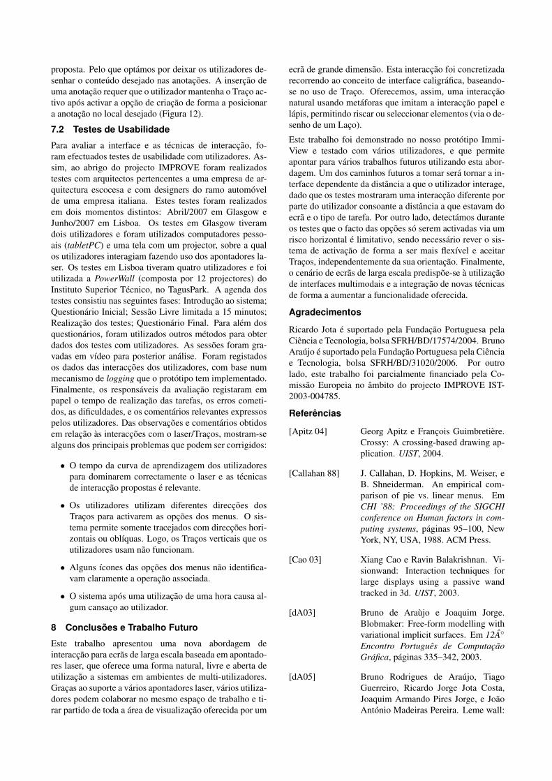
proposta. Pelo que optamos por deixar os utilizadores de-senhar o conteudo desejado nas anotacoes. A insercao deuma anotacao requer que o utilizador mantenha o Traco ac-tivo apos activar a opcao de criacao de forma a posicionara anotacao no local desejado (Figura 12).
7.2 Testes de Usabilidade
Para avaliar a interface e as tecnicas de interaccao, fo-ram efectuados testes de usabilidade com utilizadores. As-sim, ao abrigo do projecto IMPROVE foram realizadostestes com arquitectos pertencentes a uma empresa de ar-quitectura escocesa e com designers do ramo automovelde uma empresa italiana. Estes testes foram realizadosem dois momentos distintos: Abril/2007 em Glasgow eJunho/2007 em Lisboa. Os testes em Glasgow tiveramdois utilizadores e foram utilizados computadores pesso-ais (tabletPC) e uma tela com um projector, sobre a qualos utilizadores interagiam fazendo uso dos apontadores la-ser. Os testes em Lisboa tiveram quatro utilizadores e foiutilizada a PowerWall (composta por 12 projectores) doInstituto Superior Tecnico, no TagusPark. A agenda dostestes consistiu nas seguintes fases: Introducao ao sistema;Questionario Inicial; Sessao Livre limitada a 15 minutos;Realizacao dos testes; Questionario Final. Para alem dosquestionarios, foram utilizados outros metodos para obterdados dos testes com utilizadores. As sessoes foram gra-vadas em vıdeo para posterior analise. Foram registadosos dados das interaccoes dos utilizadores, com base nummecanismo de logging que o prototipo tem implementado.Finalmente, os responsaveis da avaliacao registaram empapel o tempo de realizacao das tarefas, os erros cometi-dos, as dificuldades, e os comentarios relevantes expressospelos utilizadores. Das observacoes e comentarios obtidosem relacao as interaccoes com o laser/Tracos, mostram-sealguns dos principais problemas que podem ser corrigidos:
• O tempo da curva de aprendizagem dos utilizadorespara dominarem correctamente o laser e as tecnicasde interaccao propostas e relevante.
• Os utilizadores utilizam diferentes direccoes dosTracos para activarem as opcoes dos menus. O sis-tema permite somente tracejados com direccoes hori-zontais ou oblıquas. Logo, os Tracos verticais que osutilizadores usam nao funcionam.
• Alguns ıcones das opcoes dos menus nao identifica-vam claramente a operacao associada.
• O sistema apos uma utilizacao de uma hora causa al-gum cansaco ao utilizador.
8 Conclusoes e Trabalho Futuro
Este trabalho apresentou uma nova abordagem deinteraccao para ecras de larga escala baseada em apontado-res laser, que oferece uma forma natural, livre e aberta deutilizacao a sistemas em ambientes de multi-utilizadores.Gracas ao suporte a varios apontadores laser, varios utiliza-dores podem colaborar no mesmo espaco de trabalho e ti-rar partido de toda a area de visualizacao oferecida por um
ecra de grande dimensao. Esta interaccao foi concretizadarecorrendo ao conceito de interface caligrafica, baseando-se no uso de Traco. Oferecemos, assim, uma interaccaonatural usando metaforas que imitam a interaccao papel elapis, permitindo riscar ou seleccionar elementos (via o de-senho de um Laco).
Este trabalho foi demonstrado no nosso prototipo Immi-View e testado com varios utilizadores, e que permiteapontar para varios trabalhos futuros utilizando esta abor-dagem. Um dos caminhos futuros a tomar sera tornar a in-terface dependente da distancia a que o utilizador interage,dado que os testes mostraram uma interaccao diferente porparte do utilizador consoante a distancia a que estavam doecra e o tipo de tarefa. Por outro lado, detectamos duranteos testes que o facto das opcoes so serem activadas via umrisco horizontal e limitativo, sendo necessario rever o sis-tema de activacao de forma a ser mais flexıvel e aceitarTracos, independentemente da sua orientacao. Finalmente,o cenario de ecras de larga escala predispoe-se a utilizacaode interfaces multimodais e a integracao de novas tecnicasde forma a aumentar a funcionalidade oferecida.
Agradecimentos
Ricardo Jota e suportado pela Fundacao Portuguesa pelaCiencia e Tecnologia, bolsa SFRH/BD/17574/2004. BrunoAraujo e suportado pela Fundacao Portuguesa pela Cienciae Tecnologia, bolsa SFRH/BD/31020/2006. Por outrolado, este trabalho foi parcialmente financiado pela Co-missao Europeia no ambito do projecto IMPROVE IST-2003-004785.
Referencias
[Apitz 04] Georg Apitz e Francois Guimbretiere.Crossy: A crossing-based drawing ap-plication. UIST, 2004.
[Callahan 88] J. Callahan, D. Hopkins, M. Weiser, eB. Shneiderman. An empirical com-parison of pie vs. linear menus. EmCHI ’88: Proceedings of the SIGCHIconference on Human factors in com-puting systems, paginas 95–100, NewYork, NY, USA, 1988. ACM Press.
[Cao 03] Xiang Cao e Ravin Balakrishnan. Vi-sionwand: Interaction techniques forlarge displays using a passive wandtracked in 3d. UIST, 2003.
[dA03] Bruno de Araujo e Joaquim Jorge.Blobmaker: Free-form modelling withvariational implicit surfaces. Em 12A◦
Encontro Portugues de ComputacaoGrafica, paginas 335–342, 2003.
[dA05] Bruno Rodrigues de Araujo, TiagoGuerreiro, Ricardo Jorge Jota Costa,Joaquim Armando Pires Jorge, e JoaoAntonio Madeiras Pereira. Leme wall:

Desenvolvendo um sistema de multi-projeccao. paginas 191–196, October2005.
[Dachselt 07] Raimund Dachselt e Anett Hubner.Virtual environments: Three-dimensional menus: A survey andtaxonomy. Comput. Graph., 31(1):53–65, 2007.
[Davis 02] James Davis e Xing Chen. Lumipoint:Multi-user laser-based interaction onlarge tiled displays. Displays, 2002.
[Deering 95] Michael F. Deering. Holosketch: a vir-tual reality sketching/animation tool.ACM Trans. Comput.-Hum. Interact.,2(3):220–238, 1995.
[Guimbretiere 00] Francois Guimbretiere e Terry Wino-grad. Flowmenu: combining com-mand, text, and data entry. Em UIST’00: Proceedings of the 13th annualACM symposium on User interfacesoftware and technology, paginas 213–216, New York, NY, USA, 2000. ACMPress.
[Hopkins 91] Don Hopkins. The design and imple-mentation of pie menus. Dr. Dobb’s J.,16(12):16–26, 1991.
[Hur 06] H. Hur, T. Fleisch, T.-B. Kim, e G. On.Aici-advanced immersive collaborativeinteraction framework. 2006.
[Igarashi 99] Takeo Igarashi, Satoshi Matsuoka, eHidehiko Tanaka. Teddy: A sket-ching interface for 3d freeform de-sign. Proceedings of SIGGRAPH 99,paginas 409–416, August 1999. ISBN0-20148-560-5. Held in Los Angeles,California.
[Jacoby 92] R. H. Jacoby e S. R. Ellis. Using virtualmenus in a virtual environment. EmProceedings of SPIE, Visual Data In-terpretation, 1992.
[Lapointe 05] Jean-Francois Lapointe e Guy Godin.On-screen laser spot detection for largedisplay interaction. HAVE, 2005.
[Myers 02] Brad A. Myers, Rishi Bhatnagar, Jef-frey Nichols, Choon Hong Peck, DaveKong, Robert Miller, e A. Chris Long.Interacting at a distance: Measuringthe performance of laser pointers andother devices. CHI, 2002.
[Nealen 05] Andrew Nealen, Olga Sorkine, MarcAlexa, e Daniel Cohen-Or. A sketch-based interface for detail-preserving
mesh editing. Em SIGGRAPH’05: ACM SIGGRAPH 2005 Papers,paginas 1142–1147, New York, NY,USA, 2005. ACM Press.
[Oh 02] Ji-Young Oh e Wolfgang Stuerzlinger.Laser pointers as collaborative pointingdevices. CHI, 2002.
[Olsen 01] Dan R. Olsen e Travis Nielsen. Laserpointer interaction. SIGCHI, 2001.
[OPE07] Opensg, 2007. http://opensg.org.
[OSG07] Open-source groupware architecture,2007. http://osga.net.
[Pereira 03] Joao Paulo Pereira, Joaquim A. Jorge,Vasco A. Branco, e Fernando NunesFerreira. Calligraphic interfaces: Mi-xed metaphors for design. Em DSV-IS,paginas 154–170, 2003.
[Santos 04] P. Santos e A.Stork. Smartsketches: Amultimodal approach to improve usa-bility in the early states of product de-sign. Em International Society Techno-logies Programme, 2004.
[Shesh 04] Amit Shesh e Baoquan Chen. Smart-paper: An interactive and user friendlysketching system. Comput. Graph. Fo-rum, 23(3):301–310, 2004.
[Stork 06] Andre Stork, Pedro Santos, Tho-mas Gierlinger, Alain Pagani, CelinePaloc, Inigo Barandarian, GiuseppeConti, Raffaele de Amicis, Martin Wit-zel, Oliver Machui, Jose M. Jimenez,Bruno Rodrigues de Araujo, JoaquimArmando Pires Jorge, e Georg Bodam-mer. Improve: An innovative applica-tion for collaborative mobile mixed re-ality design review. November 2006.
[Tse 04] Edward Tse, Jonathan Histon, Sta-cey D. Scott, e Saul Greenberg. Avoi-ding interference: How people use spa-tial separation and partitioning in sdgworkspaces. Em CSCW ’04, paginas252–261. ACM Press, 2004.
[Welch 06] Greg Welch e Gary Bishop. An intro-duction to the kalman filter. Relatoriotecnico, University of North Carolina,2006.
[Zeleznik 96] Robert C. Zeleznik, Kenneth P. Hern-don, e John F. Hughes. SKETCH:An Interface for Sketching 3D Scenes.Em SIGGRAPH 96 Conference Proce-edings, paginas 163–170, 1996.