Embed Size (px)
Citation preview
UDK 621.43:62—76:519.61/.64
Uporaba numerične analize pri konstruiranju tesnjenja glave motorja Applying Numerical Analysis in Cylinder Head Gasket DesignRAJKO MARINČIČ - FRANO DAMJANIČ - RADISLAV PAVLETIČ
Opisana je tehnika termo-mehanske analize tesnilnega sklopa glave motorja z metodo končnih elementov. Tehnika vključuje hkratno reševanje toplotnega in mehanskega sistema enačb, s čimer dobimo prirastke temperatur in pomikov za vsak časovni interval. Nelinearno obnašanje tesnilnega materiala je simulirano z elastoviskoplastičnim modelom. Za izboljšanje simuliranja celotnega tesnilnega sklopa in medsebojnega delovanja njegovih sestavnih delov so v program vključeni kontaktni elementi. Modeliranje kompozitne strukture tesnila glave motorja je izboljšano z ojačilnimi elementi. Uporabnost razvite tehnike in računalniškega programa je ponazorjena z nekaj praktičnimi primeri.
A finite element technique for the thermo-mechanical analysis of combustion seal systems is described. The technique involves concurrent solving of a semi-coupled set of thermal and mechanical equations within a time interval to provide both the thermal and displacement increments. An elasto-viscoplastic model is employed to simulate the non-linear behaviour of the gasket body. Joint elements are included to improve the simulation of whole sealing structure and interaction between its parts. Modelling of composite structure of the cylinder head gasket is improved by reinforcement elements. Some numerical examples illustrate the applicability of both the technique and the code developed.
0 UVOD
Na funkcionalnost tesnjenja glave motorja vpliva toliko parametrov, da ga le s težavo analiziramo na običajni način analize tesnilnega sklopa z diagramom posedanja. V nobenem primeru ne moremo v taki analizi zajeti vseh toplotnih in mehanskih pogojev ter obnašanja tesnilnega materiala v različnih obremenitvenih področjih in pogojih, ki se pojavljajo med obratovanjem motorja. Take kompleksne primere lahko uspešno analiziramo z numeričnimi metodami. V ta namen je razvit program za termo-mehansko analizo konstrukcij po metodi končnih elementov THEVISA 111. Za osnovo je uporabljen program z ločeno toplotno in mehansko analizo v dveh dimenzijah oziroma osni simetriji, v katerem je za nelinearno obnašanje tesnilnega materiala uporabljen elastoviskoplastični model. Lastnosti teh materialov v diagramu a — e so odvisne od obremenitve, temperature, časa itn. in jih z nekim običajnim modelom obnašanja materiala težko dovolj natančno popišemo. Simuliranje kom- pozitnega materiala je dodatno izboljšano z vključitvijo ojačilnih elementov v osnovni računalniški program. Ti elementi pomenijo nosilno pločevino v tesnilu. Modeliranje celotnega tesnilnega sklopa je izboljšano z dopolnitvijo programa s kontaktnimi elementi. Ti omogočajo simuliranje stika dveh površin, ki se lahko med seboj premikata, z upoštevanjem trenja, in se tudi ločita ali stakneta,
0 INTRODUCTIONThere are so many influences on the func
tionality of the cylinder head sealing system that is very hard to analyse it in the standard manner with a diagram of the deformations of sealing parts. There is no way to include all thermal and mechanical loading conditions in such an analysis. So far we cannot take into account the non-linear gasket material behaviour in different loading areas and conditions that appear during the engine performance. Computational methods, the finite element method particularly, have nowadays the potential capacity to overcome these difficulties. We developed the finite element technique THEVISA 111 for the transient thermo-mechanical analysis of the combustion seal system under operating conditions. The computer code is based on ein axi-symmetric programme with semi-coupled (staggered) algorithm of thermal and mechanical analysis, where a visco-plastic model is adopted to simulate the non-linear behaviour of sealing material (»elastometal«). The properties of these materials in a — s diagram depend on loading, temperatures, time, etc. and cannot be completely provided by some standard model of material behaviour. Therefore the composite sealing material simulation is additionally improved with inclusion of reinforcement elements into the fundamental programme. These elements represent a perforated metal layer of gasket body. We have also to add contact (joint) elements to improve the modelling of the whole cylinder head sealing system. Joint elements
če se pojavi ustrezno obremenitveno stanje. Uporabnost tega programa bomo prikazali na praktičnih primerih analize posameznih delov in celotnega tesnilnega sklopa glave motorja. Rezultati so izdelani s programom FEDRAW [21.
provide a simulation of contact between two surfaces that can slide onto each other with adoption of friction and can be separated or touched in relation to loading conditions. The results are obtained by FEDRAW (21.
1 KRATEK OPIS FORMULACIJE METODE KONČNIH ELEMENTOV
Pri tukaj opisani metodi ločeno rešujemo v vsakem časovnem intervalu dva sistema enačb — za prenos toplote in ravnotežne enačbe za mehansko obnašanje materiala. Pri tem dobimo prirastek temperatur in deformacij, s tem da pri deformacijah upoštevamo tudi toplotne spremembe. Tako gre pravzaprav za delno združeno termomehansko analizo. Za oba sistema je uporabljena ista mreža osemvozliščnih izoparametričnih končnih elementov. Podrobnejšo razlago najdemo v literaturi [31 do 151.
1.1 Toplotna analiza in ustrezna toplotna obtežba
Temperaturno polje Tn mora v vsakem časovnem koraku zadovoljiti naslednji sistem enačb:
1 BRIEF DESCRIPTION OF FINITE ELEMENT FORMULATION
The solution technique described in this section involves concurrently solving a semi-coupled set of equations - the transient heat transfer and the incremental equilibrium equations - within a time interval to provide both the temperature and displacement increments. However, the same finite element mesh of eight-node isoparametric elements is employed. Detailed formulations can be found in [31 to I5I.
1.1 Thermal analysis and equivalent thermal load
The temperature field Tn at any instant of time tn must satisfy the following equation system:
K(Tn)Tn + C(Tn)Tn + F(Tn, tn) = 0 ( 1 ) ,
kjer sta K in C matriki toplotne prevodnosti in kapacitivnosti toplote, ki sta lahko temperaturno odvisni, F pa pomeni toplotno obremenitev, ki se lahko spreminja s temperaturo in časom. S časovno diskretizacijo zgornje enačbe dobimo algoritem reševanja, ki da temperaturno polje oziroma spremembo temperatur A Tn = Tn+1 - Tn v časovnem koraku Afn = fn+1 - tn . Algoritem reševanja tega sistema enačb, njegova stabilnost in natančnost so podrobno opisani v 151 do [71. Iz temperaturne spremembe ATn izračunamo s koeficientom temperaturne razteznosti arT = aT ( Tn) toplotne specifične deformacije As* in iz njih z uporabo matrike elastičnosti Dn prirastek termičnih napetosti (2), ki ga kasneje vključimo kot ekvivalentno toplotno obtežbo v mehanskem obremenitvenem vektorju (5):
in which K and C are, respectively, the thermal conductivity and heat capacity matrices, which may be temperature dependent, and F represents the thermal loading that may vary with respect to both temperature and time. Employing the time discretization of (1) results in the solution algorithm for the variation of temperature A Tn == Tn+i - Tn within a time interval Afn = tn+1 - tn. The algorithm is fully described and its stability and accuracy extensively discussed in [51 to [71. As the temperature increment A Tn is evaluated, the corresponding thermal strain increment Af„ can be computed in a standard manner using the thermal expansion coefficient aT = ocT{Tn). The equivalent stress increment associated with temperature change (2) (where Dn is the elasticity matrix) is added as equivalent thermal load into the mechanical load vector (5):
Atf‘ = Dn A ^ (2).
1.2 ElastoviskoplastiCni model obnaSanja materiala
1.2 An elasto-visco-plastic model of material behaviour
Viskoplastično tečenje je določeno s skalarnim Visco-plastic flow is governed by a scalarkriterijem tečenja [81: yield criterion 181:
kjer je cs0 2 enoosna meja tečenja, ki je lahko odvisna od parametra utrjevanja x in temperature. Hitrost viskoplastičnih deformacij je določena z enačbo viskoplastičnega zakona tečenja:
in which <?0 2 is a one-axial yield stress that can depend on hardening parameter x and on temperature. The visco-plastic strain rate is given by equation of visco-plastic flow rule:
(4),
kjer je / parameter tečenja, pa funkcijatečenja, ki je različna od 0 samo za F >0. Ce izrazimo celotne deformacije s prirastkom pomikov A un in viskoplastično komponento po Euler- jevi integracijski shemi, je prirastek napetosti podan z enačbo :
in which y is a fluidity parameter and [F )y is the flow function taken as non-zero for F>0 only. Expressing the total strain in terms of the displacement increment Aun and the visco-plastic component according to an Euler forward difference, scheme, the stress increment is given by:
= ^ n ( ^ nAun - inP Afn) - Ac?* (5),
kjer je deformacijska matrika Bn = B konstantna za majhne deformacije. Z upoštevanjem zgornje enačbe v prirastkovni obliki ravnotežne enačbe izračunamo prirastek pomikov:
in which the strain-displacement matrix Bn = B is constant for small deformations. Substituting(5) in an incremental form of the equilibrium equations results in the displacement increment:
Aun = x C A V n ,
kjer je TKn trenutna togostna matrika, AVn = = A f n+ A /’nvp + A/„ +A <pn prirastek navidezne obtežbe, kjer pomeni A / n vektor spremembe zunanjih vozliščnih obremenitev, A spremembo obtežbe zaradi viskoplastičnega tečenja , A/^ spremembo ekvivalentne toplotne obtežbe, A ipn pa je vektor neuravnoteženih sil v času fn:
1.3 Kontaktni elementi
TKn = / 0 B TZ>nd fi (6),
where jK n is the current stiffness matrix, while AVn = A/n + A + A/p + àtpn is the incremental pseudo-load vector in which A/n represents the change of the equivalent nodal forces due to mechanical loads, A /^p the changes due to visco- -plastic flow £^p, A/^ the changes due to equivalent thermal loads, while Aipn represents the residual or out-of-balance forces at the time station fn:
- c?*) dß + f n * f* (7).
1.3 Contact elements
Za modeliranje stika dveh površin, med katerima imamo trenje, poleg tega pa se lahko tudi razmakneta in spet stakneta, so v program vključeni posebni elementi, ki sta jih razvila Sa in Owen ter so podrobneje predstavljeni v 191, 1101. Za simuliranje trenja je uporabljena plastična teorija trenja, ki jo je oblikoval Frederiksson 1111. Relativni pomiki v katerikoli točki kontaktnega elementa ter normalne in strižne deformacije so definirani z:
kjer sta in rn relativna pomika v lokalnem koordinatnem sistemu Q;-r]), tg in tn pomika zgornje, bg in b^ pa pomika spodnje polovice elementa in s - 0 deb elina elementa. Vektor specifičnih deformacij in vektor napetosti v diskreti- zirani obliki sta:
For modelling of contact between two surfaces with friction and the possibility of separation or touching, so-called joint elements are added to the programme. They have been developed by Sa and Owen and are described in detail in 191, 1101. The plastic theory of friction, formulated by Frederiksson [111, is employed to simulate friction. The relative displacements are measured at any point along the contact element, and then the normal and shear strains are given by:
( 8) ,
where rg and rn are relative displacements in the local coordinate system (%-rj), tg and t n are the displacements of the top side, while b^ and t n are the displacements of the bottom side of the element, s - 0 is the element thickness. Discretiza- ted forms of strain and stress vectors are:
o = — Nu = Businand
0 “
E = Ds, (9),
kjer je E veliko število, GA pa je strižni modul.V celotnem sistemu ravnotežnih enačb se kontaktni elementi kažejo kot dodatni elementi s togostno matriko:
K = J b TD B l / (“1 ■
Razviti in vključeni v program so tudi toplotni kontaktni elementi, saj bi se v sicer s kontaktnimi elementi povezani površini obnašali kot popolnoma izolirani. Elementi so šestvozliščni in izhajajo iz povsem enake teorije kakor osnovni. Imajo toplotno prevodnost, nimajo pa kapacitivnosti, ker toplota praktično ne potrebuje časa za prehod skoznje, saj so dejansko brez debeline. Na račun neodvisnosti od časa se enačbe (1) bistveno poenostavijo, saj odpade člen spremembe temperature.
1.4 OjaCilni elementi
in which E is some large number and GA is a shear modulus. Joint elements are seen in the onset of equilibrium equations as additional elements with stiffness matrix:
2
d f (10).
The thermal contact elements were also developed and included into the computer code. In the opposite case the surfaces connected with joint elements would have been totally insulated. These are six-node elements based on the same theory as standard ones. They have heat conductivity, but they do not have heat capacity — the heat does not need time to go through them, because they are without thickness in reality. Because of time independence the equations (1) become greatly simplified — we do not have a derivative of temperature.
1.4 Reinforcement elementsOjačilni element 131 je linijski ali membran
ski element, vključen v osnovnega. Načelno je lahko postavljen poljubno, vendar se enačbe bistveno poenostavijo, če leži na konstantni lokalni koordinati osnovnega elementa. Tako je lega ojačitve določena z rj = r)c ali f = f c. Za definicijo geometrijske oblike uporabimo iste oblikovne funkcije, kakršne ima osnovni element. Ob predpostavki popolne združljivosti med osnovnim in ojačilnim elementom so pomiki v ojačitvi določeni iz polja pomikov osnovnega elementa ue:
Po transformaciji iz ojačevalnega (x,' y ’) prek lokalnega (£ rj) v globalni (v, y) koordinatni sistem dobimo ustrezno deformacijsko matriko, ki je za vozlišče i:
The reinforcement element 131 is represented as a line or membrane element included into the standard one. It can lie anywhere in the basic element, but the equations are greatly simplified if it lies at constant local coordinate of the basic element. Therefore, the position of reinforcement is defined as rj = r)c or £ = f c. The geometry is defined by the same shape functions as the basic element. Supposing total compatibility between the basic and the reinforcement element, the displacements of reinforcement are determined from the displacement field of basic element ue:
■>.) { “; } - * " • <»>•
After a transformation from the reinforcement (X; y ’) over the local (£ rj) to the global {x, y) coordinate system we get the corresponding strain- -displacement matrix, which is in the node i:
d = _l r (— \2 — i. + ( dx d y \ dNiLU-fJ 9* J a yTogostna matrika ojačevalnega elementa je
izpeljana na običajni način in je KOE. Osnovni element ima lahko poljubno število ojačitev nOE, v različnih smereh in na različnih koordinatah. Končno togostno matriko ojačanega elementa K dobimo s seštevanjem togostne matrike osnovnega elementa Kse in togostnih matrik posameznih ojačitev v njem KOE :
■Kqe = B ̂D B df) ,
The stiffness matrix of the reinforcement element is developed in the standard manner and is Koe. The basic element can include several reinforcements nOE in different directions and at different positions. Summing the stiffness matrices of the basic (standard) element KSE, and all of the reinforcement elements KOE w ithin it, results in the final stiffness matrix of reinforced element K:
K ~ K S e + 2 K o e (1 3 ).^OE
2 PRIMERI ANALIZ TESNILNIH KONSTRUKCIJ 2 EXAMPLES OF SEALING STRUCTURE ANALYSIS2.1 Analiza tesnilne zveze glave motorja 2.1 Analysis of cylinder head gasket structure
Omejiti se moramo na obravnavo razmer okoli We must restrict our computations to theenega valja, ki ga lahko simuliramo z ustreznim situation around one cylinder that can be axi- osnosimetričnim modelom. Zaradi stvarnejšega symmetrically simulated. In order to obtain a
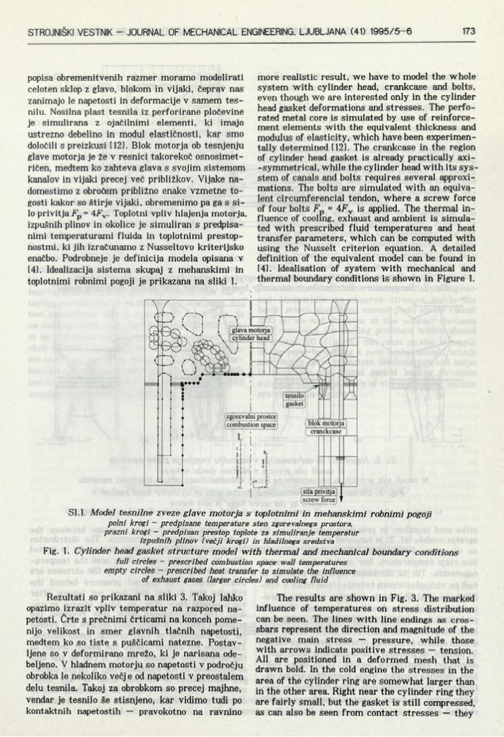
popisa obremenitvenih razmer moramo modelirati celoten sklop z glavo, blokom in vijaki, čeprav nas zanimajo le napetosti in deformacije v samem tesnilu. Nosilna plast tesnila iz perforirane pločevine je simulirana z ojačilnimi elementi, ki imajo ustrezno debelino in modul elastičnosti, kar smo določili s preizkusi 1121. Blok motorja ob tesnjenju glave motorja je že v resnici takorekoč osnosimet- ričen, medtem ko zahteva glava s svojim sistemom kanalov in vijaki precej več približkov. Vijake nadomestimo z obročem približno enake vzmetne togosti kakor so štirje vijaki, obremenimo pa ga s silo privitja Fp = 4Fv . Toplotni vpliv hlajenja motorja, izpušnih plinov in okolice je simuliran s predpisanimi temperaturami fluida in toplotnimi prestop- nostmi, ki jih izračunamo z Nusseltovo kriterijsko enačbo. Podrobneje je definicija modela opisana v 141. Idealizacija sistema skupaj z mehanskimi in toplotnimi robnimi pogoji je prikazana na sliki 1.
more realistic result, we have to model the whole system with cylinder head, crankcase and bolts, even though we are interested only in the cylinder head gasket deformations and stresses. The perforated metal core is simulated by use of reinforcement elements with the equivalent thickness and modulus of elasticity, which have been experimentally determined 1121. The crankcase in the region of cylinder head gasket is already practically axi- -symmetrical, while the cylinder head with its sys- stem of canals and bolts requires several approximations. The bolts are simulated with an equivalent circumferencial tendon, where a screw force of four bolts Fp = 4FV is applied. The thermal influence of cooling, exhaust and ambient is simulated with prescribed fluid temperatures and heat transfer parameters, which can be computed with using the Nusselt criterion equation. A detailed definition of the equivalent model can be found in 141. Idealisation of system with mechanical and thermal boundary conditions is shown in Figure 1.
Sl. 1. Model tesnilne zveze glave motorja s toplotnimi in mehanskimi robnimi pogoji polni krogi - predpisane temperature sten zgorevalnega prostora,
prazni krogi - predpisan prestop toplote za simuliranje temperatur izpušnih plinov (večji krogi) in hladilnega sredstva
Fig. 1. Cylinder head gasket structure model with thermal and mechanical boundary conditions full circles - prescribed combustion space wall temperatures
empty circles - prescribed heat transfer to simulate the influence of exhaust gases (larger circles) and cooling fluid
Rezultati so prikazani na sliki 3. Takoj lahko opazimo izrazit vpliv temperatur na razpored napetosti. Črte s prečnimi črticami na konceh pomenijo velikost in smer glavnih tlačnih napetosti, medtem ko so tiste s puščicami natezne. Postavljene so v deformirano mrežo, ki je narisana odebeljeno. V hladnem motorju so napetosti v področju obrobka le nekoliko večj e od napetosti v preostalem delu tesnila. Takoj za obrobkom so precej majhne, vendar je tesnilo še stisnjeno, kar vidimo tudi po kontaktnih napetostih — pravokotno na ravnino
The results are shown in Fig. 3. The marked influence of temperatures on stress distribution can be seen. The lines with line endings as crossbars represent the direction and magnitude of the negative main stress — pressure, while those with arrows indicate positive stresses — tension. All are positioned in a deformed mesh that is drawn bold. In the cold engine the stresses in the area of the cylinder ring are somewhat larger than in the other area. Right near the cylinder ring they are fairly small, but the gasket is still compressed, as can also be seen from contact stresses — they
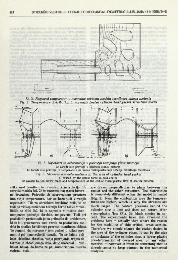
Sl. 2. Razpored temperatur v normalno ogretem modelu tesnilnega sklopa motorja Fig. 2. Temperature distribution in normally heated cylinder head gasket structure model
SI. 3. Napetosti in deformacije v področju tesnjenja glave motorja a) zaradi sile privitja v hladnem stanju motorja
b) zaradi sile privitja in temperature na koncu viskoplastičnega tečenja tesnilnega materialaFig. 3. Stresses and deformations in the area of cylinder head gasket
a) caused by the screw force in cold engineb) caused by the screw force and temperatures at the end of visco-plastic flow of sealing material
stika med tesnilom in preostalo konstrukcijo. Po ogretju modela (sl. 2) je razpored napetosti bistveno drugačen. Področje ob zgorevalnem prostoru ima višjo temperaturo, kar se kaže tudi v večjih napetostih. Tik za obrobkom izgubimo stik, ki se tudi po viskoplastičnem tečenju (črne točke v vozliščih na sliki 3b), ki je največje v močno obremenjenem področju obrobka, ne povrne. Tudi pri praktičnih preizkusih je tu prihajalo do problemov, ki so bili pravzaprav tudi vzrok za postavitev modela in analizo kritičnega prereza tesnilnega sklopa. To pomeni, da moramo v tem področju nekaj spremeniti pri konstrukciji tesnila. To so lahko velikost, debelina obrobka, večja poprejšnja trajna deformacija obrobljenega dela, drug material — vsekakor nekaj, da bomo že pri numeričnem modelu obdržali stik.
are drawn perpendicular to plane between the gasket and the other structure. The distribution is completely different when the model is heated (Fig. 2). Near the combustion area the temperatures are higher, which is why the stresses are much larger. The contact pressure behind the cylinder ring is lost and does not return after visco-plastic flow (Fig. 3b, black circles in nodes). The experiments have also revealed the problems here — actually they where the reason for the modelling of this critical cross-section. Therefore we should change the gasket design in the area of the cylinder rings. It can be the size or thickness of the cylinder ring, a larger plastic pre-deformation of covered area, or any other material — however it must be something that is already going to keep contact in the numerical analysis.
2.2 Obremenitve v območju tesnilne gubepri kovinskih tesnilih clave motorja
Večplastna kovinska tesnila tesnijo z vzmetnimi lastnostmi gub kovinskih plasti. Gube morajo ustvariti dovolj velike pritiske na tesnjene površine, pri tem pa se ne smejo plastično deformirati, ker bi se lahko zaradi tega v določenih obremenitvenih razmerah preveč zmanjšal tesnilni pritisk. Poleg tega moramo natančno določiti deformacije tesnila pri vgradnji, saj je običajno kot konstrukcijska zahteva definirana debelina tesnila v vgrajenem stanju 1121.
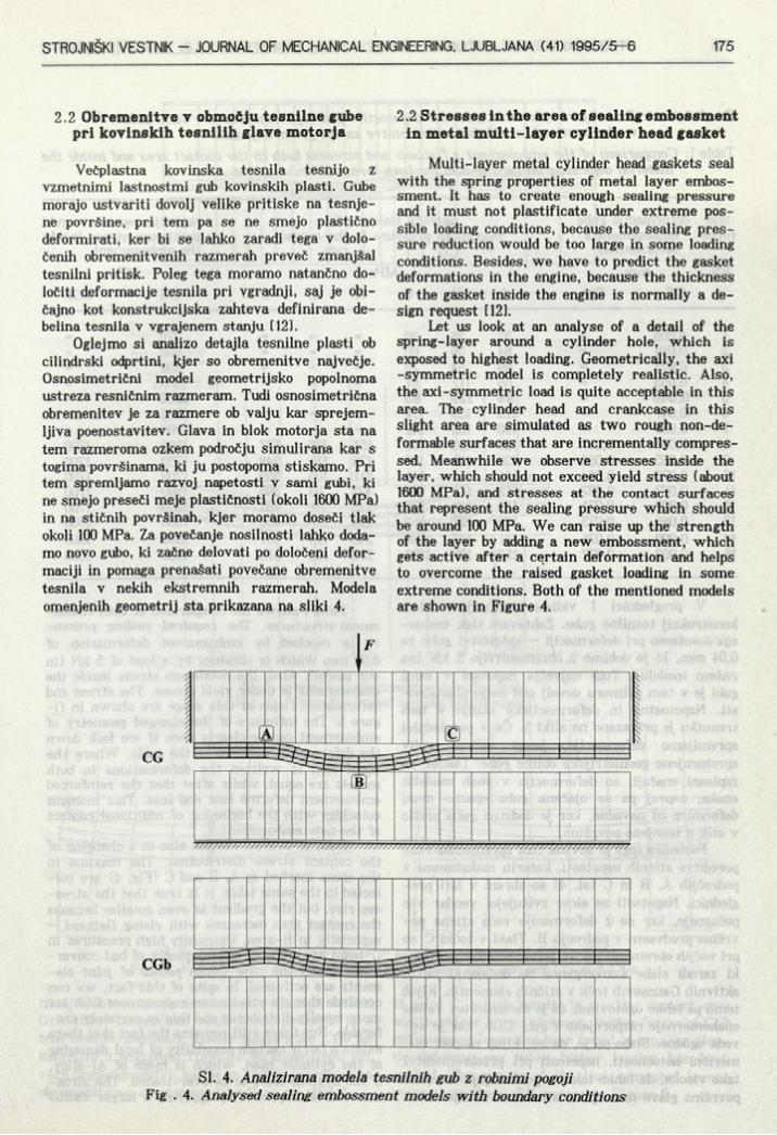
Oglejmo si analizo detajla tesnilne plasti ob cilindrski odprtini, kjer so obremenitve največje. Osnosimetrični model geometrijsko popolnoma ustreza resničnim razmeram. Tudi osnosimetrična obremenitev je za razmere ob valju kar sprejemljiva poenostavitev. Glava in blok motorja sta na tem razmeroma ozkem področju simulirana kar s togima površinama, ki ju postopoma stiskamo. Pri tem spremljamo razvoj napetosti v sami gubi, ki ne smejo preseči meje plastičnosti (okoli 1600 MPa) in na stičnih površinah, kjer moramo doseči tlak okoli 100 MPa. Za povečanje nosilnosti lahko dodamo novo gubo, ki začne delovati po določeni deformaciji in pomaga prenašati povečane obremenitve tesnila v nekih ekstremnih razmerah. Modela omenjenih geometrij sta prikazana na sliki 4.
2.2 Stresses in the area of sealing embossment in metal m ulti-layer cylinder head casket
Multi-layer metal cylinder head gaskets seal with the spring properties of metal layer embossment. It has to create enough sealing pressure and it must not plastificate under extreme possible loading conditions, because the sealing pressure reduction would be too large in some loading conditions. Besides, we have to predict the gasket deformations in the engine, because the thickness of the gasket inside the engine is normally a design request 1121.
Let us look at an analyse of a detail of the spring-layer around a cylinder hole, which is exposed to highest loading. Geometrically, the axi -symmetric model is completely realistic. Also, the axi-symmetric load is quite acceptable in this area. The cylinder head and crankcase in this slight area are simulated as two rough non-de- formable surfaces that are incrementally compressed. Meanwhile we observe stresses inside the layer, which should not exceed yield stress ( about 1600 MPa), and stresses at the contact surfaces that represent the sealing pressure which should be around 100 MPa. We can raise up the strength of the layer by adding a new embossment, which gets active after a certain deformation and helps to overcome the raised gasket loading in some extreme conditions. Both of the mentioned models are shown in Figure 4.
SI. 4. Analizirana modela tesnilnih gub z robnimi pogoji Fig . 4. Analysed sealing embossment models with boundary conditions
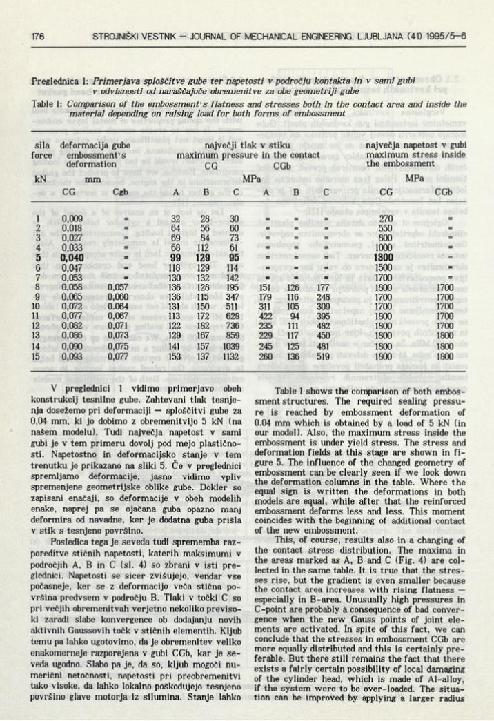
Preglednica 1: Primerjava sploščitve gube ter napetosti v področju kontakta in v sami gubi v odvisnosti od naraščajoče obremenitve za obe geometriji gube
Table 1: Comparison of the embossment's flatness and stresses both in the contact area and inside the materia] depending on raising load for both forms of embossment
sila deformacija gube največji tlak v stiku največja napetost v gubiforce embossment’s maximum pressure in the contact maximum stress inside
deformation CG CGb the embossmentkN mm MPa MPa
CG Cgb A B C A B C CG CGb
1 0,009 _ 32 28 30 _ _ _ 270 _2 0,018 = 64 56 60 = = = 550 =3 0,027 = 69 84 73 = = = 800 =4 0,033 = 68 112 61 = = = 1000 =5 0,040 = 99 129 95 = = = 1300 =6 0,047 = 118 129 114 = = = 1500 =7 0,053 = 130 132 142 = = = 1700 =8 0,058 0,057 136 128 195 151 126 177 1800 17009 0,065 0,060 136 115 347 179 116 248 1700 1700
10 0,072 0.064 131 150 511 311 105 309 1700 170011 0,077 0,067 113 172 628 422 94 395 1800 170012 0,082 0,071 122 182 736 235 111 482 1800 170013 0,086 0,073 129 167 859 229 117 450 1800 180014 0,090 0,075 141 157 1039 245 125 481 1800 180015 0,093 0,077 153 137 1132 260 136 519 1800 1800
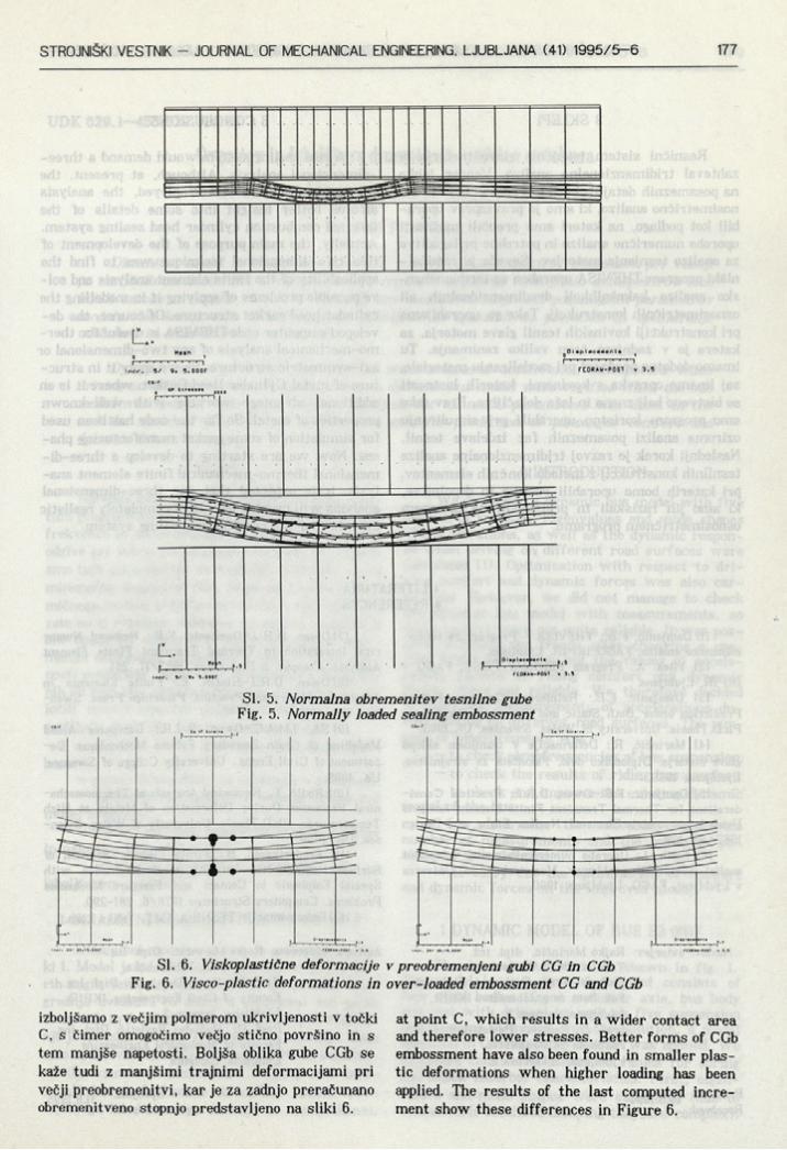
V preglednici 1 vidimo primerjavo obeh konstrukcij tesnilne gube. Zahtevani tlak tesnje- nja dosežemo pri deformaciji — sploščitvi gube za 0,04 mm, ki jo dobimo z obremenitvijo 5 kN (na našem modelu). Tudi največja napetost v sami gubi je v tem primeru dovolj pod mejo plastičnosti. Napetostno in deformacijsko stanje v tem trenutku je prikazano na sliki 5. Če v preglednici spremljamo deformacije, jasno vidimo vpliv spremenjene geometrijske oblike gube. Dokler so zapisani enačaji, so deformacije v obeh modelih enake, naprej pa se ojačana guba opazno manj deformira od navadne, ker je dodatna guba prišla v stik s tesnjeno površino.
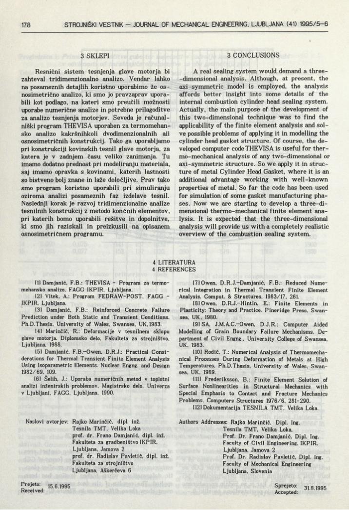
Posledica tega je seveda tudi sprememba razporeditve stičnih napetosti, katerih maksimumi v področjih A, B in C (sl. 4) so zbrani v isti preglednici. Napetosti se sicer zvišujejo, vendar vse počasneje, ker se z deformacijo veča stična površina predvsem v področju B. Tlaki v točki C so pri večjih obremenitvah verjetno nekoliko previsoki zaradi slabe konvergence ob dodajanju novih aktivnih Gaussovih točk v stičnih elementih. Kljub temu pa lahko ugotovimo, da je obremenitev veliko enakomerneje razporejena v gubi CGb, kar je seveda ugodno. Slabo pa je, da so, kljub mogoči numerični netočnosti, napetosti pri preobremenitvi tako visoke, da lahko lokalno poškodujejo tesnjeno površino glave motorja iz si lumina. Stanje lahko
Table 1 shows the comparison of both embossment structures. The required sealing pressure is reached by embossment deformation of 0.04 mm which is obtained by a load of 5 kN (in our model). Also, the maximum stress inside the embossment is under yield stress. The stress and deformation fields at this stage are shown in figure 5. The influence of the changed geometry of embossment can be clearly seen if we look down the deformation columns in the table. Where the equal sign is written the deformations in both models are equal, while after that the reinforced embossment deforms less and less. This moment coincides with the beginning of additional contact of the new embossment.
This, of course, results also in a changing of the contact stress distribution. The maxima in the areas marked as A, B and C (Fig. 4) are collected in the same table. It is true that the stresses rise, but the gradient is even smaller because the contact area increases with rising flatness — especially in B-area. Unusually high pressures in C-point are probably a consequence of bad convergence when the new Gauss points of joint elements are activated. In spite of this fact, we can conclude that the stresses in embossment CGb are more equally distributed and this is certainly preferable. But there still remains the fact that there exists a fairly certain possibility of local damaging of the cylinder head, which is made of Al-alloy, if the system were to be over-loaded. The situation can be improved by applying a larger radius
Di eplacBienta
5/ 9. 5.000F FEDRAW-P0S1 v 3.5
Sl. 5. Normalna obremenitev tesnilne gube
Sl. 6. Viskoplastične deformacije v preobremenjeni gubi CG in CGb Fig. 6. Visco-plastic deformations in over-loaded embossment CG and CGb
izboljšamo z večjim polmerom ukrivljenosti v točki C, s čimer omogočimo večjo stično površino in s tem manjše napetosti. Boljša oblika gube CGb se kaže tudi z manjšimi trajnimi deformacijami pri večji preobremenitvi, kar je za zadnjo preračunano obremenitveno stopnjo predstavljeno na sliki 6.
at point C, which results in a wider contact area and therefore lower stresses. Better forms of CGb embossment have also been found in smaller plastic deformations when higher loading has been applied. The results of the last computed increment show these differences in Figure 6.
3 SKUEPI
Resnični sistem tesnjenja glave motorja bi zahteval tridimenzionalno analizo. Vendar lahko na posameznih detajlih koristno uporabimo že os- nosimetrično analizo, ki smo jo pravzaprav uporabili kot podlago, na kateri smo preučili možnosti uporabe numerične analize in potrebne prilagoditve za analizo tesnjenja motorjev. Seveda je računalniški program THEVISA uporaben za termomehan- sko analizo kakršnihkoli dvodimenzionalnih ali osnosimetričnih konstrukcij. Tako ga uporabljamo pri konstrukciji kovinskih tesnil glave motorja, za katera je v zadnjem času veliko zanimanja. Tu imamo dodatno prednost pri modeliranju materiala, saj imamo opravka s kovinami, katerih lastnosti so bistveno bolj znane in laže določljive. Prav tako smo program koristno uporabili pri simuliranju oziroma analizi posameznih faz izdelave tesnil. Naslednji korak je razvoj tridimenzionalne analize tesnilnih konstrukcij z metodo končnih elementov, pri katerih bomo uporabili rešitve in dopolnitve, ki smo jih raziskali in preizkusili na opisanem osnosimetričnem programu.
3 CONCLUSIONS
A real sealing system would demand a three- -dimensional analysis. Although, at present, the axi-symmetric model is employed, the analysis affords better insight into some details of the internal combustion cylinder head sealing system. Actually, the main purpose of the development of this two-dimensional technique was to find the applicability of the finite element analysis and solve possible problems of applying it in modelling the cylinder head gasket structure. Of course, the developed computer code THEVISA is useful for thermo-mechanical analysis of any two-dimensional or axi-symmetric structure. So we apply it in structure of metal Cylinder Head Gasket, where it is an additional advantage working with well-known properties of metal. So far the code has been used for simulation of some gasket manufacturing phases. Now we are starting to develop a three-dimensional thermo-mechanical finite element analysis. It is expected that the three-dimensional analysis will provide us with a completely realistic overview of the combustion sealing system.
4 LITERATURA 4 REFERENCES
(11 Damjanić, F.B.: THEVISA - Program za termo- mehansko analizo, FAGG IKPIR, Ljubljana.
121 Vitek, A.: Program FEDRAW-POST, FAGG - IKPIR, Ljubljana.
131 Damjanić, F.B.: Reinforced Concrete Failure Prediction under Both Static and Transient Conditions. Ph.D.Thesis, University of Wales, Swansea, UK, 1983.
141 Marinčič, R.: Deformacije v tesnilnem sklopu glave motorja. Diplomsko delo. Fakulteta za strojništvo, Ljubljana, 1988.
151 Damjanić, F.B.-Owen, D.R.J.: Practical Considerations for Thermal Transient Finite Element Analysis Using Isoparametric Elements. Nuclear Engng. and Design 1982/69, 109.
161 Selih, J.: Uporaba numeričnih metod v toplotni analizi inženirskih problemov, Magistrsko delo, Univerza v Ljubljani, FAGG, Ljubljana, 1990.
Naslovi avtorjev: Rajko Marinčič, dipl. inž.Tesnila TMT, Velika Lokaprof. dr. Frano Damjanić, dipl. inž.Fakulteta za gradbeništvo IKPIR,Ljubljana, Jamova 2prof. dr. Radislav Pavletič, dipl. inž.Fakulteta za strojništvoLjubljana, Aškerčeva 6
[71 Owen, D.R.J.-Damjanić, F.B.: Reduced Numerical Integration in Thermal Transient Finite Element Analysis. Comput. & Structures, 1983/17, 261.
181 Owen, D.R.J.-Hintin, E.: Finite Elements in Plasticity: Theory and Practice. Pineridge Press, Swansea, UK, 1980.
191 SA, J.M.A.C.-Owen, D.J.R.: Computer Aided Modelling of Grain Boundary Failure Mechanisms. Department of Civil Engng., University College of Swansea, UK, 1983.
1101 Rodič, T.: Numerical Analysis of Thermomechanical Processes During Deformation of Metals at High Temperatures, Ph.D.Thesis, University of Wales, Swansea, UK, 1989.
111! Frederiksson, B.: Finite Element Solution of Surface Nonlinearities in Structural Mechanics with Special Emphasis to Contact and Fracture Mechanics Problems, Computers Structures 1976/6, 281-290.
[121 Dokumentacija TESNILA TMT, Velika Loka.
Authors Addresses: Rajko Marinčič, Dipl. Ing.Tesnila TMT, Velika Loka,Prof. Dr. Frano Damjanić, Dipl. Ing. Faculty of Civil Engineering, IKPIR, Ljubljana, Jamova 2 Prof. Dr. Radislav Pavletič, Dipl. ing. Faculty of Mechanical Engineering Ljubljana, Slovenia
Prejeto: 15 6 lg95Received:
Sprejeto:Accepted: 31.8.1995