Embed Size (px)
Citation preview
•
•
Unsymmetrical plate Girders
STRENGTH FORMULAS FOR DESIGNOF STEEL PLATE GIRDERS
by
Alexis OstapenkoChingmiin Chern
Siamak. Parsanejad
This work was conducted as part of the project UnsymmetricalPlate Girders, sponsored by the American Iron and Steel Institute,the Pennsylvania Department "of Transportation, the Federal HighwayAdministration of the U. S. Department of Transportation, and theWelding Research Council •. The findings and conclusions expressedin this report are those of the authors and not necessarily thoseof the sponsors.
Department of Civil EngineeringFritz Engineering Laboratory
Lehigh UniversityBethlehem, Pennsylvania
January 1971
Fritz Engineering Laboratory Report No. 328.12
p
•
•
~28.l2
STRENGTH FORMULAS FOR DESIGNOF STEEL PLATE GIRDERS
by
Alexis Ostapenko 1
Chingmiin Chern2
Siamak Parsanejad 3
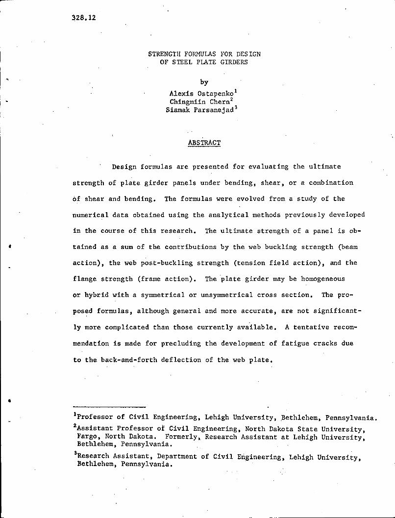
ABSTRACT
Design formulas are presented for evaluating the ultimate
strength of plate girder panels under bending, shear, or a combination
of shear and bending. The formulas were evolved from a study of the
numerical data obtained using the analytical methods previously developed
in the course of this research. The ultimate strength of a panel is ob-
tained as a sum of the contributions by the web buckling strength (beam
action), the web post-buckling strength (tension field action), and the
flange strength (frame action). The 'plate girder may be homogeneous
or hybrid with a symmetrical or unsYmmetrical cross section. The pro-
posed formulas, although general and more accurate, are not significant-
ly more complicated than those currently available. A tentative recom-
mendation is made for precluding the development of fatigue cracks due
to the back-and-forth deflection of the web plate •
Iprofessor of Civil Engineering, Lehigh University, Bethlehem, Pennsylvania.
2Assistant Professor of Civil Engineering, North Dakota State University,Fargo, North Dakota. Formerly,. Research Assistant at Lehigh University,Bethlehem, Pennsylvania. .
'Research Assistant, Department of Civil Engineering, Lehigh University,Bethlehem, Pennsylvania.
••
328.12 -1
1. INTRODUCTION
The considerable post-buckling strength of plate girder
webs has been tacitly recognized in design by using lower factors
of safety against buckling than against yielding. However, tests
showed that the relationship between the ultimate and buckling
strengths is not proportional. Thus, a consistent margin against
the ultimate strength cannot be achieved by using a constant
factor of safety in conjunction with the buckling strength - - - the
ultimate strength must be evaluated as such. (3)
Basler offered a plausible theory(3,4,~ which gave good
agreement with tes~t6) and was accepted by AlSO as the method for
designing plate girders in buildings. (2) A slightly modified
version of this theory was also incorporated in the load factor
method·proposed under auspices of AISI for designing steel
highway bridges~21) Recently, this method has been accepted by
AASHO for use in practice. (1) Further developments of tQe ultimate
strength theory were made, among others, by FUjii(13) and Rockey and
(rl) .Ska10ud who ~nc1uded.the effect of flanges on the strength of
the web plate. All these theories are based on the development of
a failure mechanism by the plate girder panel.
Djubek proposed that the maximum web stress in the post-
buckling range of deformations remain under the yield level. From
a series of theoretical computations he established the stress

328.12
amplification factors for various panel proportions to be used with
(12)the buckling stress.
All of this work has been concerned with symmetrical plate
girders, that is, girders having flanges of equal areas and therefore
the neutral axis at the mid~depth of the girder. Also, none of these
theories gave a continuous description of the girder failure mode for
-2'
a variable combination of shear and moment. To compensate for these
deficiencies, a new approach was developed by Chern and ostapenko.(8,9,lO)
This method was also successfully extended to longitudinally stiffened
plate girders(14) and confirmed by additional tests~11,18)
Since for an efficient application the method requires
use of a computer, it is hardly suitable for manual calculations.
To overcome this difficulty, the numerical computer output was utilized
to develop simplified formulas for practical USe. So far, this
approxima~ion has been successful only for transversely stiffened
plate girders and the resultant formulas are described in this report.
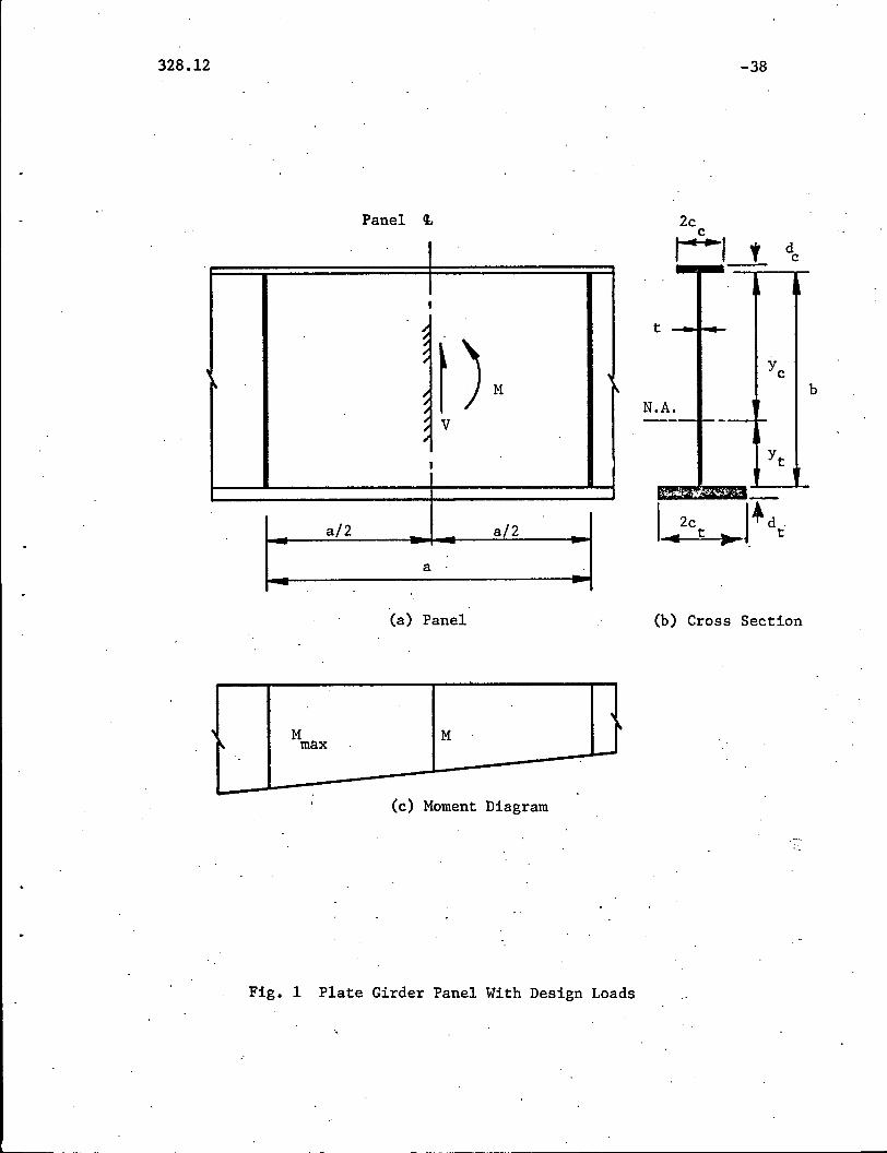
Design Conditions - A typical plate girder panel is shown in Fig. lea).
The cross section is unsymmetrical and, for the sake of discussion,
the smaller top flange is assumed to be subjected to compression
and the larger bottom flange to tension. A larger portion of the
web plate is thus under compression. The internal forces acting
in the panel are defined at the mid-length as moment Mand shear V.
As indicated in the moment diagram, Fig. l(b), a greater moment
M is developed at one end of the panel and it also should be takenmax
into consideration in design.
328.12
Since for a particular arrangement of loads on a plate
girder the moment in a panel is directly proportional to the
shear in it, it is convenient to define the moment in terms of the
shear span ratio ~.
-3
where
M = ~ b V
M=--b V
(1)
(2)
Analogously to the theory presented in References 8, 9
and 10 three loading conditions are considered here: pure bending
(V = 0), pure shear (M = 0, but M :f 0); and a combination ofmax,
shear and bending (M:f 0, V ~ 0). In the following, the strength
formulas for these cases are described separately and then their
application is illustrated with numerical examples.

328.12-4
2. ' 'BENDING'STRENGTH
It has been found that the ultimate capacity of a plate girder
panel subjected tq pure bending .is limited by the strength of the
compression or tension flange rather than by the buckling of the web
plate, although the web plate after buckling does not contribute to the
strength of the panel as much as it would if it were flat.
The effective cross section of the plate girder panel after
web buckling can be visualized to have the compression flange column
composed of the flange itself and a portion of the web plate. A method
of analysis based on such an assumption is presented in Ref.9. Good
correlation was obtained with test results on symmetrical, unsymmetrical,
hybrid and homogeneous plate girders. Although the generality of this
method is very attractive, it was desirable to compare it with the
popular method d~veloped by Basler and ThUrlimann (3) which has been
already accepted by AISC (2) and AASHO (1).
A series of sample computation showed that Basler's method agreed
quite well for symmetrical homogeneous girders and also that its familiar
and relatively simple formula could be modified to apply to unsymmetrical
*and hybrid girders. For convenience, such a modified version of the
Basler formula is recommended here.
*The approximate adaptation to unsymmetrical girders made in Ref. I, and 21 isapplicable only to plate girders with a slenderness ratio approximately lessthan 200 and is not sufficiently accurate for a general case. The methodfor hybrid girders given in Ref. 20 is limited to symmetrical girders withthe web which does not buckle before yielding.
328.12, \ - -5
is (3)
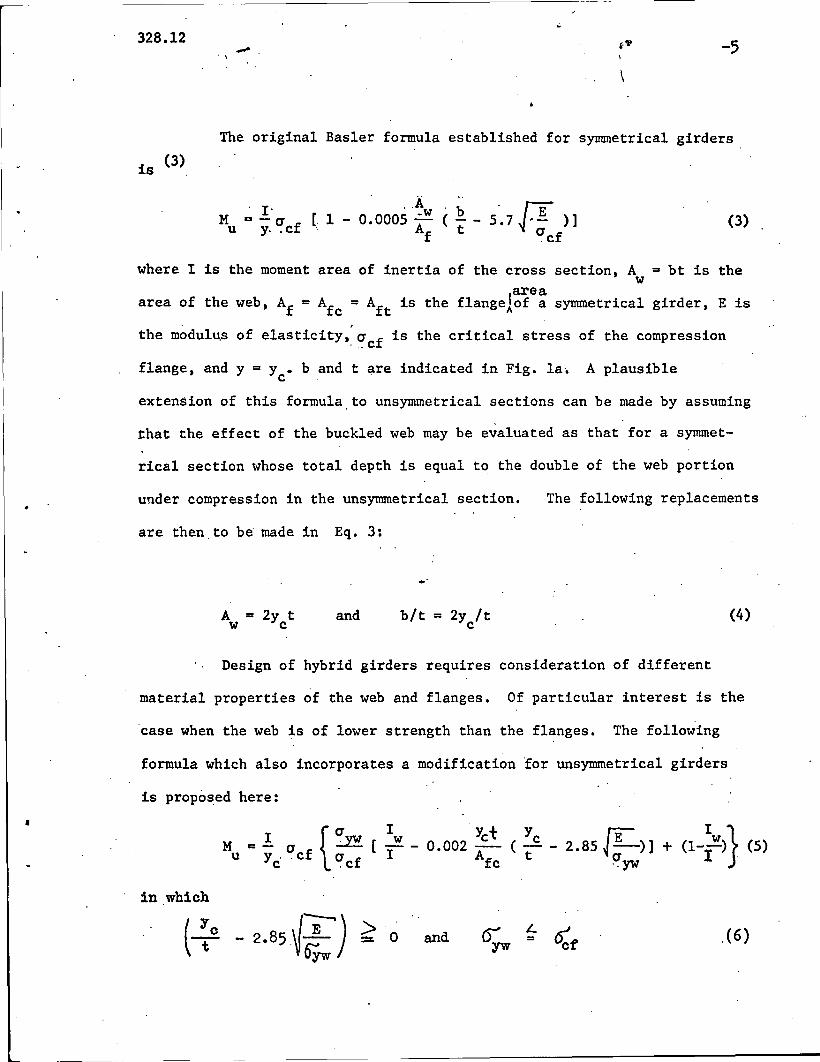
The original Basler formula established for symmetrical girders
(3)
where I is the moment area of inertia of the cross section, A = bt is thew
areaarea of the web, Af = Afc = Aft is the flangelof a symmetrical girder, E is
the modul~s of elasticity,~~cf is the critical stress of the compression
flange, and y = Yc. band t are indicated in Fig. lao A plausible
extension of this formula. to unsymmetrical sections can be made by assuming
that the effect of the buckled web may be evaluated as that for a symmet-
rical section whose total depth is equal to the double of the web portion
under compression in the unsymmetrical section.
are then,to be made in Eq. 3:
The following replacements
A = 2y tw Cand bIt = 2y Itc
(4)
Design of hybrid girders requires consideration of different
material properties of the web and flanges. Of particular interest is the
case when the web is of lower strength than the flanges. The following
formula which also incorporates a modification for unsymmetrical girders
is proposed here:
•I {UM=-u ~
u y,. cf u fc .c
in which
Iw
I'Yet Yc ~ I w }
0.002 A ( t - 2.85 ~ ;;--)] + (1--) (5)fc ~yw I,
and Dvur
;. ~t1.. °cf
,( 6)
328.12
" ,
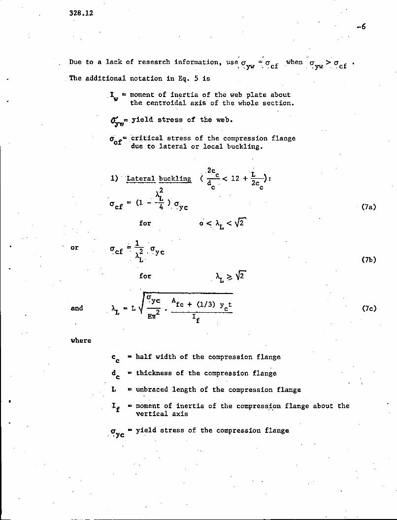
Due to a lack of research information, use a =a ,when a.yw.>, a.cf •. . yw '.. cf
The additional notation in Eq. 5 is
,Iw a moment of in~rtia of the web plate aboutthe centroida1 a~is of the whole section.
~ywa yield stress of the web.
acra ,critical stress of the compression flangedue to lateral or local buckling.
-6
or
1) , 'Lateral buckling
,>ia cf = (1 - -4 ) a, .yc
for
·1a = - a,cf " Ai.' .yc
for
,,2c 'L(~< 12 + -):
d . 2cc c
(7a)
(7b)
and
where
Afc + (1/3) y t• c
If(7c)
,
Cc a half width of the compression flange
de = thickness of the compression flange
L a unbraced length of the compression flange
If =moment of inertia of the compress~~n flange about thevertical axis
a a yield stress of the compression flange.yc '
328.12-7
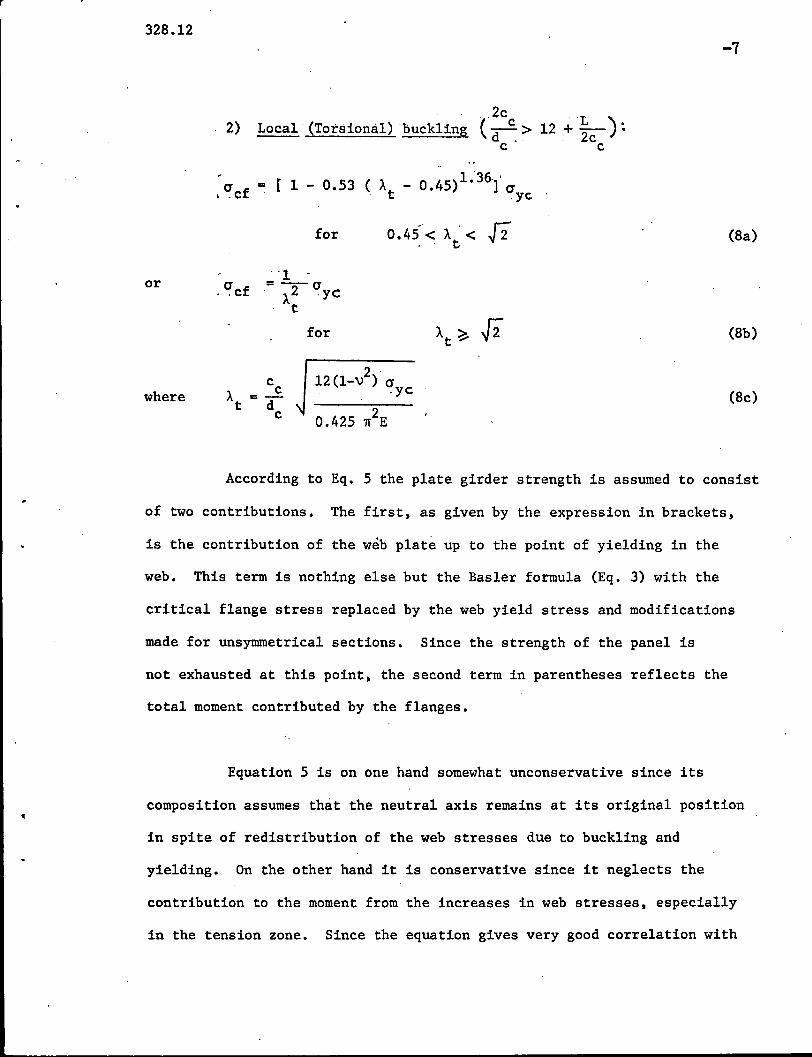
2)
I ~cf
, ,,2c 'L)Local' (Torsional) buckling (d c. > 12 .+~ ~
c c
= [ 1 - 0.53 (). - 0.45)1.36.1'. t ~yc
or
for
"1a =--a.. cf . ).2 .yc
t
for
0.45"< ). . < .[2. ' t (8a)
(8b)
where (8c)
According to Eq. 5 the plate girder strength is assumed to consist
of two contributions. The first. as given by the expression in brackets.
is the contribution of the web plate up to the point of yielding in the
web. This term is nothing else but the Basler formula (Eq. 3) with the
critical flange stress replaced by the web yield stress and modifications
made for unsymmetrical sections. Since the strength of the panel is
not exhausted at this point. the second term in parentheses reflects the
total moment contributed by the flanges.
Equation 5 is on one hand somewhat unconservative since its
composition assumes that the neutral axis remains at its original position
in spite of redistribution of the web stresses due to buckling and
yielding. On the other hand it is conservative since it neglects the
contribution to the moment from the increases in web stresses. especially
in the tension zone. Since the equation gives very good correlation with
328.12-8
(9)experimental results and a more rigorous approach , these two effects
apparently cancel each other.
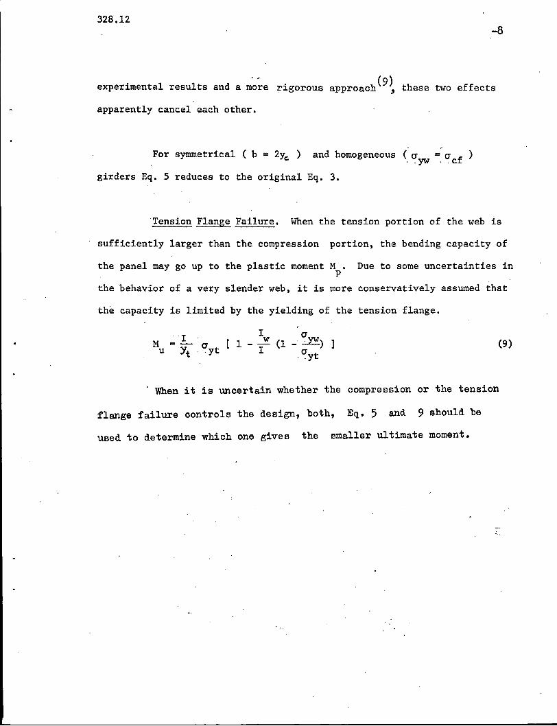
For symmetrical ( b = 2YG ) and homogeneous (0" = 0" ).. yw ,.cf
girders Eq. 5 reduces to the original Eq. 3.
Tension Flange Failure. When the tension portion of the web is
sufficiently larger than the compression portion. the bending capacity of
the panel may go up to the plastic moment M. Due to some uncertainties inp
the behavior of a very slender web. it is more conservatively assumed that
the capacity is limited by the yielding of the tension flange.
IM =-0" [1u Yt , .yt
Iw
I
0"(1 -~) ]
.<!yt(9)
. When it is uncertain whether the compression or the tension
flange failure controls the design, both, Eq. 5 and 9 should be
used to determine which one gives the smaller ultimate moment.
328.12-9
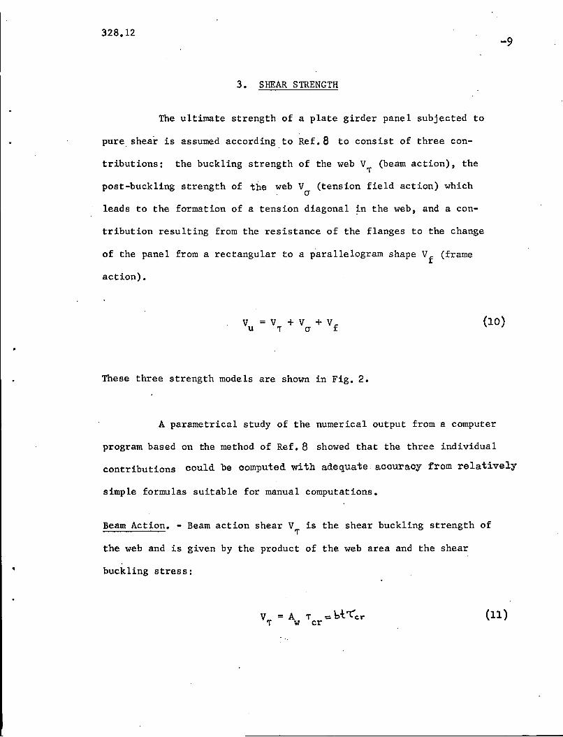
3. SHEAR STRENGTH
The ultimate strength of a plate girder panel subjected to
pure shear is assumed according to Ref. 8 to consist of three con-
tributions: the buckling strength of the web V (beam action), the,.post-buckling strength of the web V (tension field action) which
cr
leads to the formation of a tension diagonal ~n the web, and a con-
tribution resulting from the resistance of the flanges to the change
of the panel from a rectangular to a parallelogram shape Vf
(frame
action).
These three strength models are shown in Fig. 2.
(10)
A parametrica1 study of the numerical output from a computer
program based on the method of Ref. 8 showed that the three individual
contributions could be computed with adequate accuracy from relatively
simple formulas suitable for manual computations.
Beam Action. - Beam action shear V is the shear buckling strength of,.the web and is given by the product of the web area and the shear
buckling stress:
(11)
328.12
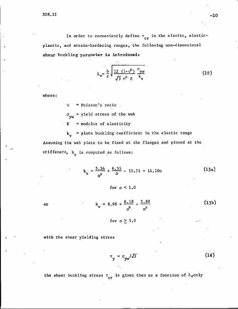
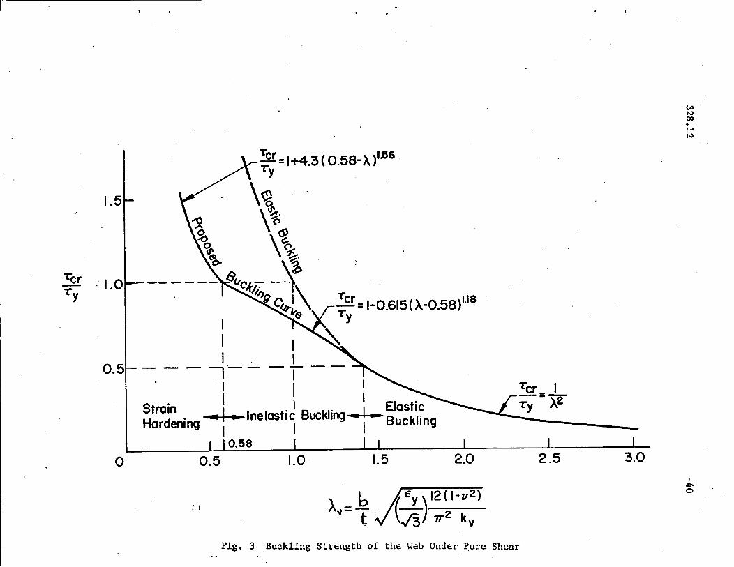
In order to conveniently define ~ in the elastic, e1asticcr
plastic, and strain-hardening ranges, the following non-dimensional
shear bU~kling parameter is introduced:
-10
where:
v = Poisson's ratio
cr = yield stress of the webyw
E =modulus of elasticity
k = plate buckling coefficient in the elastic rangev
Assuming the web plate to be fixed at the flanges and pinned at the
stiffeners, k is computed as follows:v
k = 5.34 + 6.55 _ 13.71 + l4.l0av ,;a a
for a < 1.0
(12)
(13a)
or kv
2.88---cl'
(13b)
for a ~ 1.0
with the shear yielding stress
~ = cr /./3y yw
the shear buckling stress ~ is given then as a function of Avonlycr
(14)
328.12
for Av< 0.58(strain-hardening range)
for 0.58 < Av~ J2(elastic-plastic range)
-11
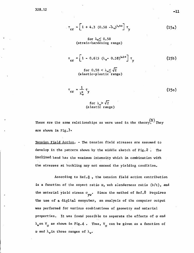
(15a)
(15b)
,.cr
1= - ,.-A2 Yy
for Ay> [2(elastic range)
(15c)
Since the method of Ref.8 requires
These are the same relationships as were used in the theory~8)They
are shown in Fig.3.
Tension Field Action. - The tension field stresses are assumed to
develop in the pattern shown by the middle sketch of Fig.2 ~ The
inclined band has the maximum intensity which in combination with
the stresses at buckling may not exceed the yielding condition.
According to Ref.8, the tension field action contribution
is a function of the aspect ratio a, web slenderness ratio (bit), and
the material yield stress cr •yw
the use of a digital computer, an analysis of tHe computer output
was performed for various combinations of geometry and material
properties. It was found possible to separate the effects of a and
A on V as shown in Fig.4. Thus, V can be given as a function ofy cr cr
a and Ayin three ranges of Av•

328.12
v = 0(J
for AV:::: 0.5"8
-12
(16a)
where
v(J
v(J
= 0.6 Ay - 0.348 V
Va? + 1.6 p
for 0.58 < Av::::J2
= 0.9 - 0.787/Ae V
'./ cl + 1.6 p
for Av> .[2
(16b)
(160)
(17)
is the plastic shear force.
Frame Action. - The frame action shear is the resistance of the flanges
to the distortion of the panel from a rectangle into a parallelogram.
The maximum frame action shear is assumed to be reached when the mech-
anism shown by the right sketch of Fig.2· is formed. Because the con-
tinuity of the web provides sufficient rigidity to, essentially, pre-
c1ude rotation of the transverse stiffener, plastic hinges are assumed
to form in the flanges.
According to the method of Ref. 8 a portion of the web plate
is assumed to act with the flanges. For the sake of simplification,
the contribution by the web plate is neglected here. Since the frame
328.12
action contribution to the ultimate panel strength is, in most cases,
about 10%, this assumption does not introduce any appreciable error in
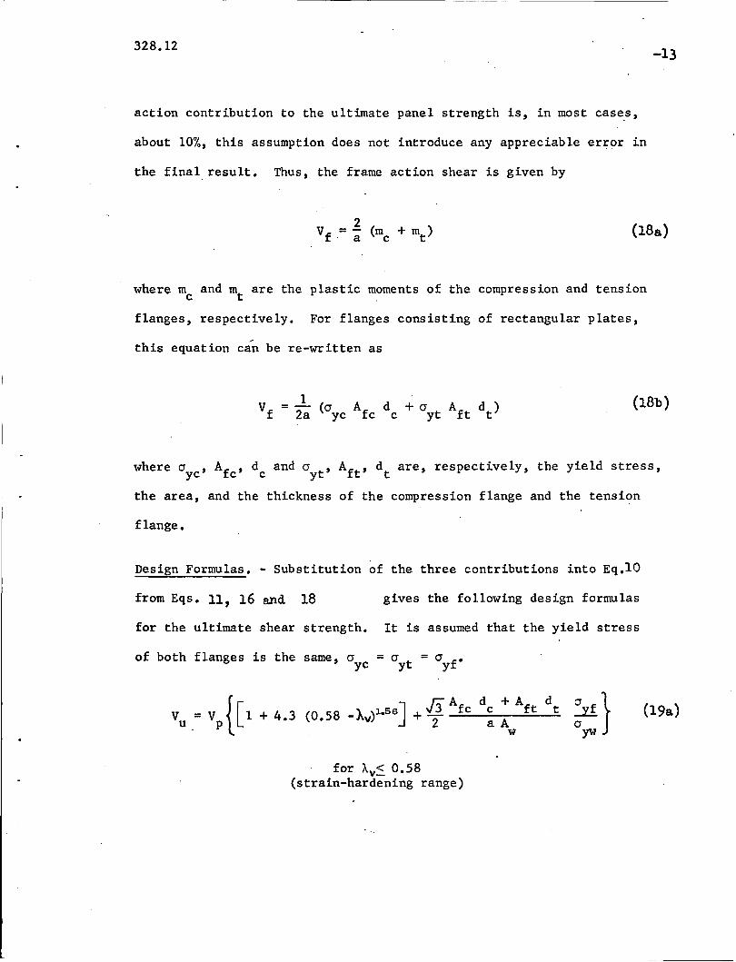
the final result. Thus, the frame action shear is given by
-13
(18a)
where me and mt
are the plastic moments of the compression and tension
flanges, respectively. For flanges consisting of rectangular plates,
this equation can be re-written as
1V
f= -- (a A d + a A
fd)
2a yc fc c yt t t(18b)
where ayc ' Afc ' dc and ayt , Aft' dt are, respectively, the yield stress,
the area, and the thickness of the compression flange and the tension
flange.
Design Formulas. - Substitution of the three contributions into Eq.lO
from Eqs. 11, 16 and 18 gives the following design formulas
for the ultimate shear strength. It is assumed that the yield stress
of both flanges is the same, a = a = a f.yc yt . Y
for Av::: 0.58(strain-hardening range)
(19a)
328.12-14
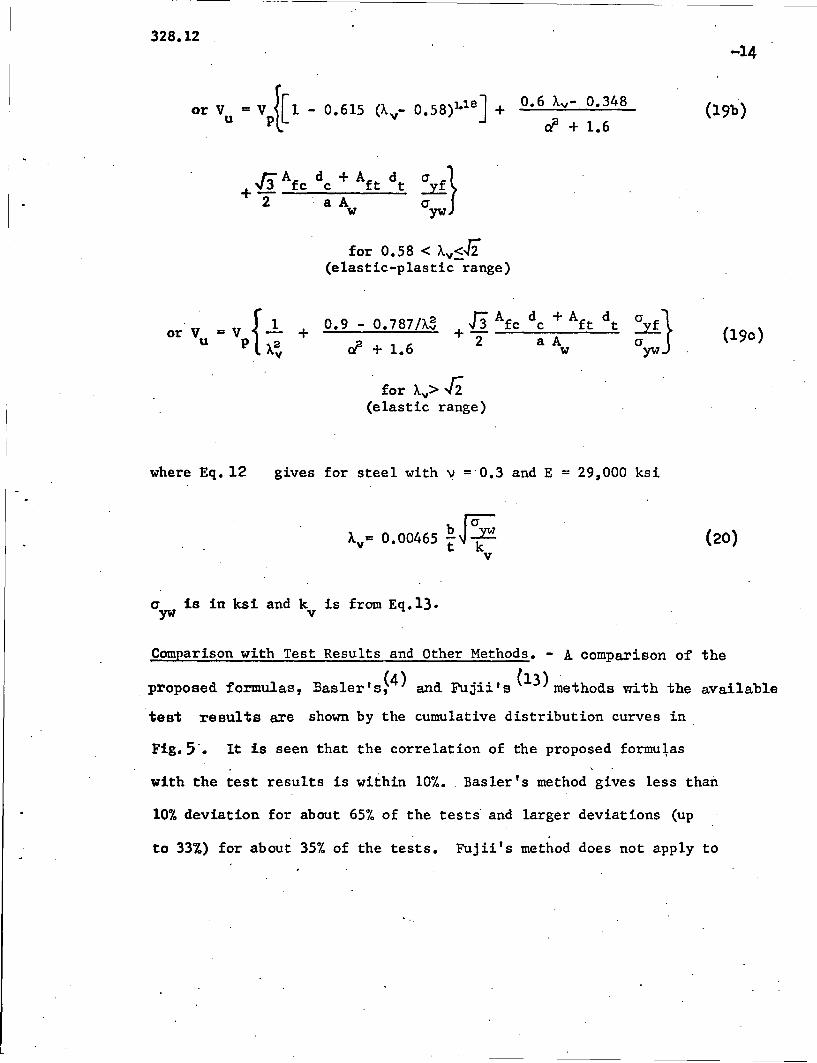
for 0.58 < Ay <-l2(elastic-p1astic-range)
(19b)
or Vu
+ 0.9 - 0.787/A~
cl + 1.6(190)
where Eq. 12
, for Ay> J2
(elastic range)
gives for steel with v = 0.3 and E = 29,000 ksi
(20)
0yw is in ksi and kv is from Eq.13.
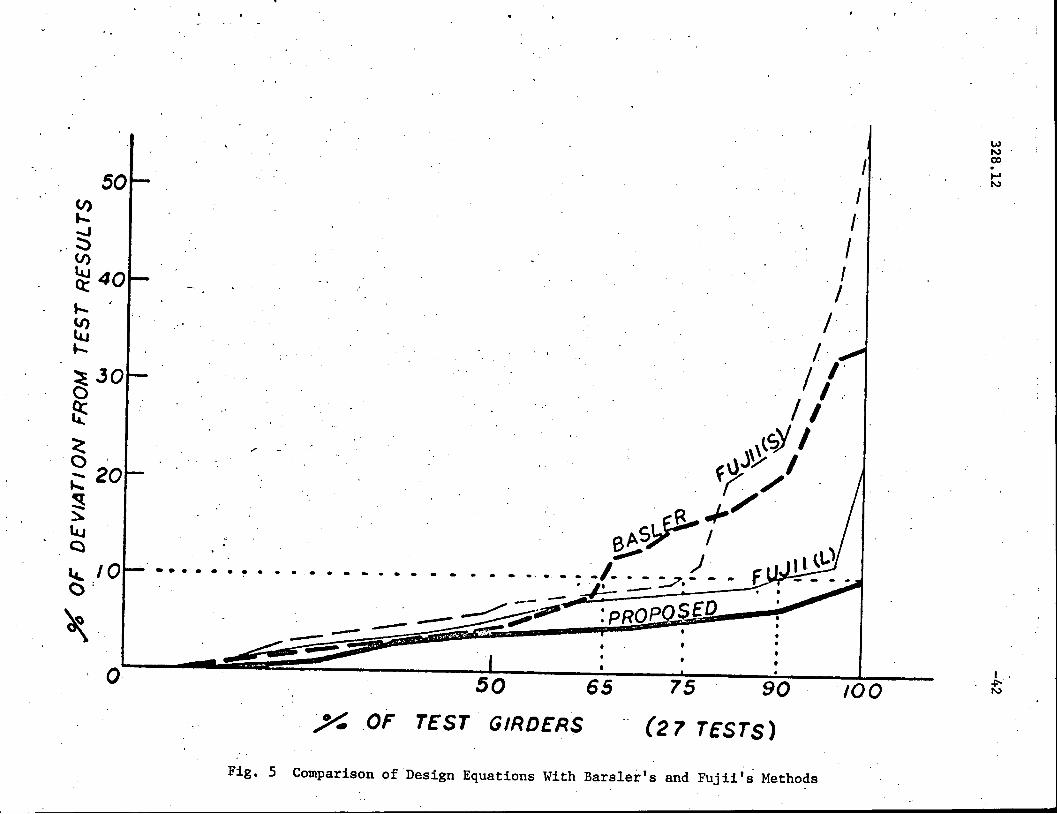
Comparison with Test Results and Other Methods. - A comparison of the
proposed formulas, Basler's~4) and Fujii's (13)~ethods with the available
test results are shown by the cumulative distribution curves in,
Fig. 5'. It is seen that the correlation of the proposed formulas
with the test results is within 10%. , Basler's method gives less than
10% deviation for about 65% of the tests' and larger deviations (up
to 33%) for about 35% of the tests. Fujii's method does not apply to
328.12
unsymmetrical plate girders. Therefore, two sets of computations
were made. The thin dashed line denoted by "S" in the figure re-
presents the Fujii's case when both flanges were assumed to be of
the smaller flange si~e, and the thin solid line denoted by "L" re
presents the case of assuming both flanges as the larger flange. It
is seen that Fujii's method gives good correlation with tests for
symmetrical girders, but the method is ambiguous when applied to un-
symmetrical girders.
End Panel. - Full development of the tension field oapaoity requires
that the neighboring panels be suffioiently strong to anchor it.
This means that either the panel at the end of a girder should have
a very strong end stiffener oapable of resisting the horizontal
component of the tension 'field_ force or that the panel should be
designed to develop only the buckling strength. The latter approach
is recommended here. Thus, the shear oapaoity of the end panel is
to be oomputed from Eq.10 with V~ = O.
The resultant shear capacity of the end panel is greater
than that specified by AASHO(l) and AISC(2)because of two reasons:
1) the web plate is assumed to be fixed at the flanges and simply
supported at, the stiffeners rather than simply supported at all
edges, and 2) the frame action shear Vf is inoluded.
328.12
4. STRENGTH UNDER BENDING AND SHEAR
-16
The strength of a plate girder panel under various combinations
of shear and moment can be described by the interaction curve G5-Q4-~ -Qa-Qa
shown in Fig.6. The ordinate gives the shear non-dimensiona1ized with
respect to the ultimate value for the pure shear case, and the abscissa
is the moment non-dimensiona1ized with respect to the ultimate moment
for pure bending. The right and left parts are, respectively, for the
larger portion of the web plate under compression and tension as indicated
by the small sketches under the diagram.
Depending on the relative magnitude of shear and moment and
on the direction of the moment, the ultimate strength of the panel may
be controlled by one of the following three conditions: 1) the shear
strength reduced by bending (web failure---portion ~ -Ql -~), 2) the
bending strength reduced by shear and limited by the compression flange
failure (portion ~-Q3)' and 3) the bending strength reduced by shear
and limited by the yielding of the tension flange (portion ~-Q4). The
mechanisms of failure are indicated by the insert sketches. The in
dividual contributions due to beam, tension field and frame actions are
shown schematically by separate areas in the interaction diagram. The
design procedure recommended here is to compute the ultimate strength
for each applicable strength condition and use the lower value as the
controlling one.
Web Failure. (Curve Q4 -~ -~ in Fig. 6 ) - As the insert in Fig. 6 shows,
the panel strength is obtained as a sum of buckling (beam action), post
buckling (tension field action), and flange (frame action) contributions.
3.28.12
This is analogous to the case of pure shear, except that now each con-
tribution is affected by the presence of bending moment.
-17
vuc = V'T"C + Vcrc + Vfc (21 )
where subscript c indicates the combined loading by shear and bending.
The beam action contribution is
V = 'T" A'T"C c w
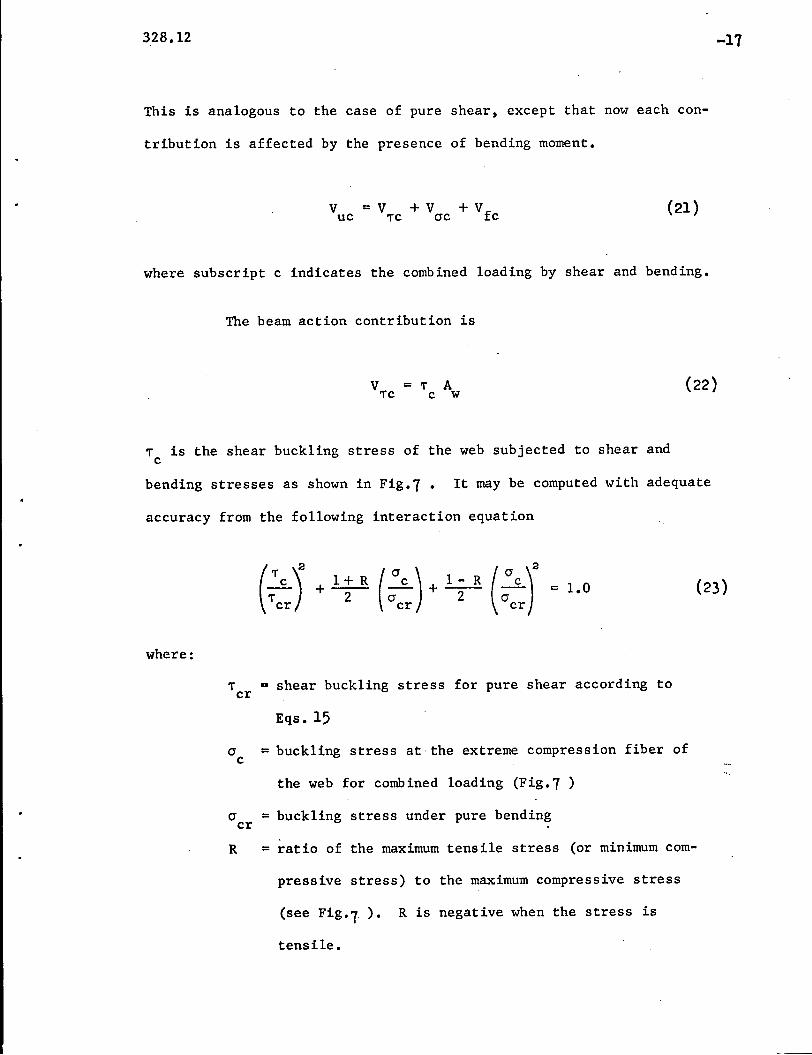
'T" is the shear buckling stress of the web subjected to shear andc
(22)
bending stresses as shown in Fig.7. It may be computed with adequate
accuracy from the following interaction equation
where:
'T" = shear buckling stress for pure shear according tocr
Eqs. 15
cr =buckling stress at the extreme compression fiber ofc
the web for combined loading (Fig.7 )
cr = buckling stress under pure bendingcr
R = ratio of the maximum tensile stress (or minimum com-
pressive stress) to the maximum compressive stress
(see Fig.l). R is negative when the stress is
tensile.
328.12
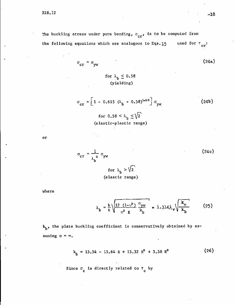
The buckling stress under pure bending, 0 ,is to be computed fromcr
-18
the following equations which are analogous to Eqs.15
for Ab ::. 0.58
(yielding)
o =[1 - 0.615 (Ab - 0.58)1.18J 0cr YW.
for 0.58 < Ab::'Vi'
(elastic-plastic range)
or
1ocr = - 0
A 2YWb
for Ab > V2(elastic range)
where
used for" :cr
(24a)
(24b)
(240)
~, the plate buckling coefficient is conservatively obtained by as-
suming ex = co.
~ = 13.54 - 15.64 R + 13.32 R2 + 3.38 R3
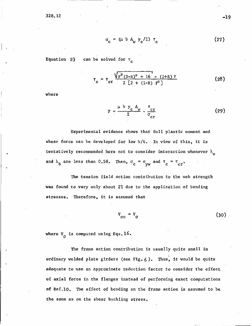
Since 0 is directly related to" byc c
(26)
328.12
ac = (~ bAy II) Tw c c
-19
(27)
Equation 23 can be solved for Tc
where
Tc= T "Fa (3-Rt + 16' - (I+R) F
cr 2 [2 + (l-R) ~ ]
~ b Y AF = c w
I
Tcr. --acr
Experimental evidence shows that' full plastic moment and
shear force can be developed for low bIt. In view of this, it is
tentatively recommended here not to consider interaction whenever Av
and Ab are less than 0.58. Then, a = a and T = T •c yw c cr
The tension field action contribution to the web strength
was found to vary only about 2% due to the application of bending
stresses. Therefore, it is assumed that
v =Vac a
where Va is computed using Eqs.16.
The frame action contribution is usually quite small in
ordinary welded plate girders (see Fig. 6). Thus, it would be quite
(30)
adequate to use an approximate reduction factor to consider the effect
of axial force in the flanges instead of performing exact computations
of Ref.lO. The effect of bending on the frame action is assumed to be
the same as on the shear buckling stress.

328.12-20
= (0 0 01 +~)V'T" fcr(31 )
where Vf is from Eq.18 (the constant 0.01 serves to simplify
computations when the strength is limited by the failure of the
compression flange).
The ultimate shear is then obtained by adding the results
of Eqs.22, 30 and 31.
Compression Flange Failure. (Curve ~ -Q3 in Fig. 6 ) - In this range of
moment-shear combinations, the compression flange fails before the web
strength can be fully developed. Thus, bending is now the principal
loading parameter. However, it is still convenient to define the panel
strength in terms of shear given as a sum of the beam, tension field
and frame action contributions.
The beam action and frame action contributions are computed
from Eqs. 22 and 31.
However, the tension field action does not fully develop and
a special study was needed to arrive at an acceptably simple formula
for its computation. The formula finally selected on the basis of a
parametrical study of the numerical computer output of the method of
Ref.10 is
=
where
VIerc
(Af + 30 t 2) (er f - er ) - IJ. Vf= __c_---:--::' ...;;;c c ~c > 0
B (~) (180)V33 b '+V bit er y IJ.er ". ywc
328.12
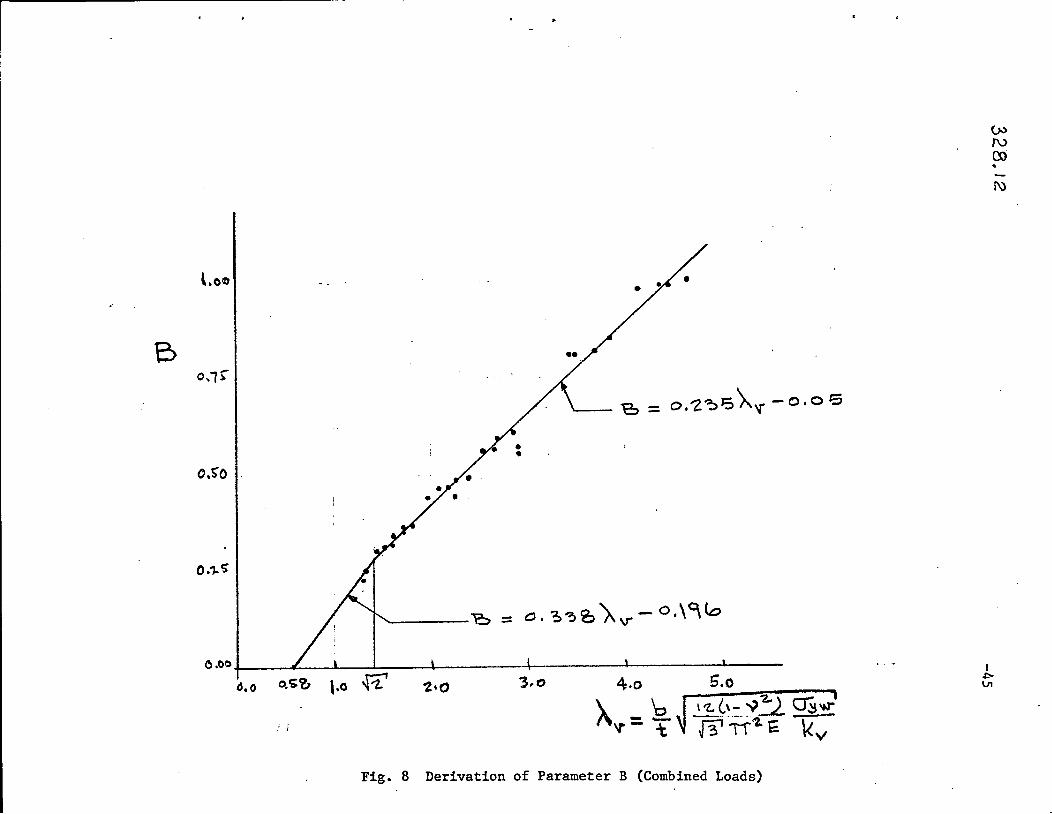
B = 0.338). - 0.196v
-21
(33a)
or B = 0.235).., - 0.05v
for A >V2v
(33b)
A is given by Eq.12v
and cr is in ksi.yw
Besides the composition of Eq.32, the parameter which
was developed from the numerical output is B. Figure 8 shows a plot
of B versus A. The points give the values of B obtained by equatingv
the .u1timate strength expressed by the design formula to the theore-
tical ultimate strength at the point of transition from web failure
to compression flange failure; each point represents a particular panel.
A least squares fit through the plotted points was used to find the
expression for B when AV
> 1[2, Eq.33b. Since for 0.58 < Av~ {2 ,
VI represents only a small portion of the total shear strength,erc
the effect of B would be negligible. Thus, a straight-line approxi-
mati~n is made, Eq.33a.
The ultimate panel shear causing failure of the compression
flange is given by the sum of the values from Eqs. 22, 31 and 32.
328.12-22
and the corresponding panel moment is
1IIuc -= M,b VI uc
;;Mu
Equation 35 indicates that Muc should not exceed M.u Since the nature
of the approximations involved in the evaluation of V~c could lead to
an unrealistic condition of M being less than M for the Case ofuc u
pure bending, the constant 0.01 was introduced into Eq.3l to pre-
clude this situation. The result is illustrated in the right lower
corner of the interaction diagram of Fig. 9.
Ultimate Strength Under Bending and Shear. - Since the specific combi-
nations of moment and shear which are controlling for the web or compre-
ssion flange failure modes are not defined, it is necessary to check
both modes and se1eot the one which gives a lower capacity.
A typical interaction diagram based on the above derived
formulas is shown in Fig. 9. A ray emanating from the origin repre-
sents an increasing load for a partioular moment-shear combination.
Two intersection points with the interaction curves are shown, one due
to web failure and the other due to the compression flange failure.
The smaller shear is to be selected as the controlling ultimate shear.
For the two rays shown, the controlling cases are indicated with the
heavy dots.
328.12
Maximum Panel Moment. - Since in a panel under combined loads the
moment at one end of the panel is greater than the mid-panel moment
used in the analysis (Fig. 1), it may happen that the strength will
be controlled by this maximum panel moment M • This is particularlymax
true for panels with large aspect ratios.
A reasonable and sufficiently accurate approach appears to
be a requirement that the maximum panel moment be below the moment
which would cause failure under pure bending.
Thus,
-23
Mu
VI =u 'b (~ + ~ a) (36)
where M is the smaller value of E~.5u
or E~.9.*
Tension Flange Yielding. - As indicated by the vertical line marked
"Flange Yielding" in Fig. 9 , the check by E~.36 also covers the case
when the panel strength is limited by the yielding of the tension
flange. This criterion may be somewhat conservative for sections with
low bit (compact sections) or in cases when most of the web is in
tension and essentially full plastic moment may be attained (see the
left-most curves in Figs.' 6 and 9 ). It is left to the judgement o'fthe designer when he would want to take advantage of the additional
panel capacity due to plastification.
*A more refined check on the compression flange capacity isfrom E~.5).
(with Mu
MVI = U
u b (~ + ~ a)
328.12
5· CONSIDERATION OF FATIGUE
-24
Many tests as well as a comprehensive study conducted speci
fically for this purpose(19) showed that initial out-of-plane deflec-
tions of the web plate have no detrimental effect on the ultimate
strength of girders subjected to static loads. However, when the load
application is repeated many times as is the Oase for bridge and crane
girders, fatigue cracks may develop in the web due to the lateral
flexing ("breathing") of the web at each load application. Initial
deflections and the amount of stressing beyond the buckling stress
level of the web plate appear' to be the principal factors influencing
the development of these fatigue cracks. (16) Since both of these
factors are functions of the web slenderness ratio bit, a recommendation
was made to limit the web slenderness ratio to a specific value.(l, 21)
This bit limitation was critically reviewed in Reference 15
in the light of additional tests on unsymmetrical ~late girders. It
was found to be somewhat conservative for conventionally proportioned
girde~s and is endorsed here till more research is conducted.
where
36,500
\/ayw'
~ is in ksi.Vyw
b
~ t (38)
328.12 -25
It should be noted, however, that Eq.38 may be unconservative
for girder panels with stiffeners of high torsional rigidity, such as
bearing stiffeners and stiffeners with closed sections. Till more
research is conducted, it is tentatively recommended here that the
web panels adjoining a torsionally rigid stiffener be proportioned
not to buckle under a load equal to about 1.1 of the working load.
328.12-26
6. GIRDERS WITHOUT INTEID:!EDIATE STIFFENERS
Plate firders having stiffeners only at the supports (bearing
stiffeners) and possibly under heavy oonoentrated loads are of oonsiderable
eoonomio interest. As desoribed in Referenoes 8 and 10, suoh plate
girders may be safely and aoourately designed by negleoting the
oontribution of the tension field aotion (post-buokling strength) whenever
the panel aspeot ratio cJ... exoeeds 3.0. Thus,
where Vto
and Vio are given by Eqs. 22 and 31, respeotively, or by
Eqs. 11 and 18 for the oase when M = O. It is important that suoh
long panels be always oheoked for the maximum panel moment acoording
to Eq. 36.
Plate girders without intermediate stiffeners and subjeoted
to uniformly distributed statio loading, suoh as roof girders, have
attraoted attention of engineers in Sweden. (7) A temporary design
specification was developed primarily on the basis of experimental
work. A oomparison of Eq. 39 with this speoifioation for a few sam~le
girders showed that for most oases Eq. 39 was more oonservative than
the speoifioation rules.
328.12 -27
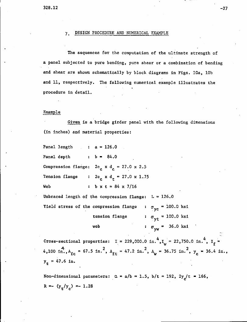
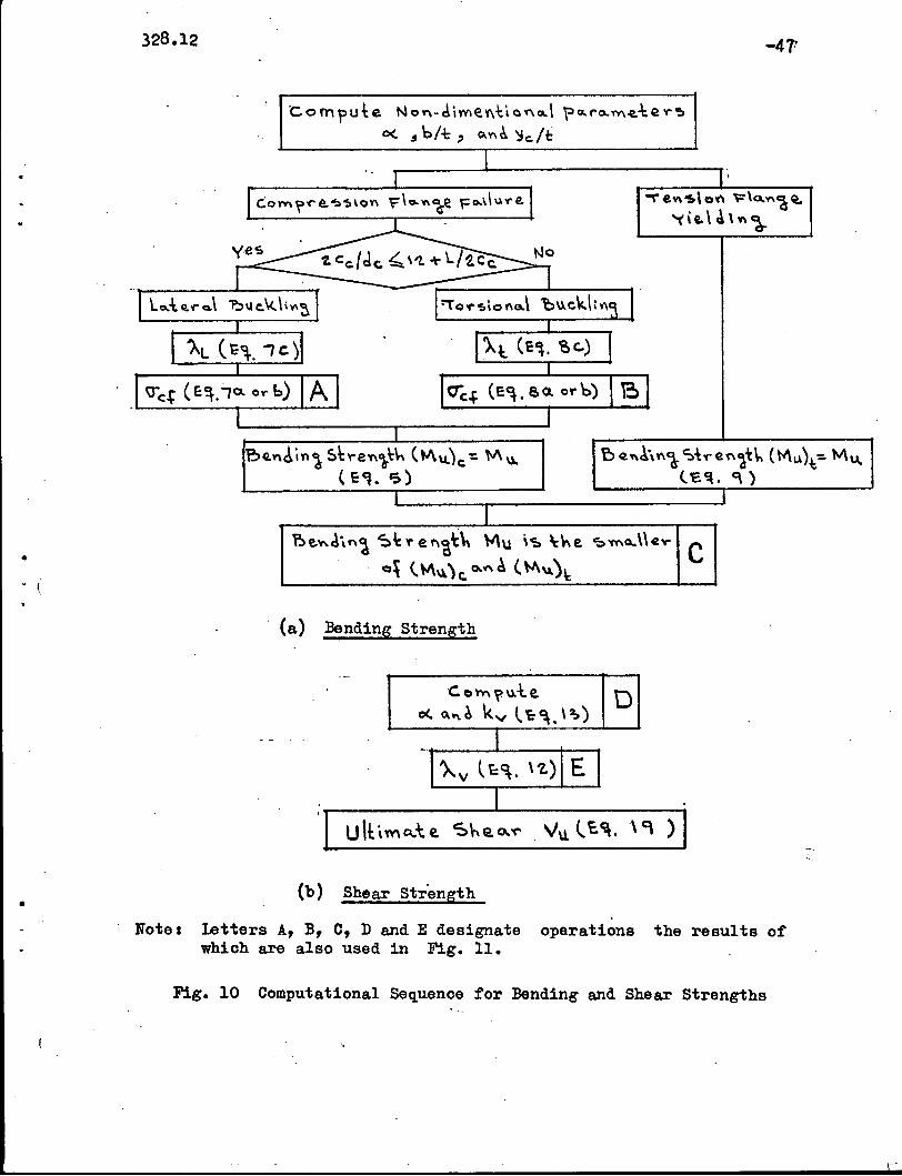
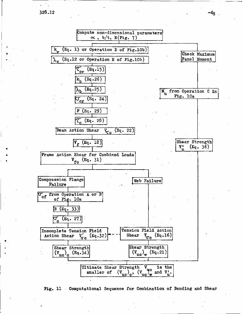
7. DESIGN PROCEDURE AND NUMERICAL EXAMPLE
The sequences for the computation of the ultimate strength of
a panel subjected to pure bending. pure shear or a combination of bending
and shear are shown schematically by block diagrams in Figs. lOa. lOb
and 11. respectively. The following numerical example illustrates the
procedure in detail.
Example
Given is a bridge girder panel with the following dimensions
(in inches) and material properties:
Panel length a = 126.0
Panel depth b = 84.0
Compression flange: 2c x d = 27.0 x 2.5c c
Tension flange 2c x dt = 27.0 x 1.75c
Web b x t = 84 x 7/16
Unbraced length of the compression flange: L = 126.0
Yield stress of the compression flange a yc = ioo.o ksi
tension flange a yt = 100.0 ksi
web ayw = 36.0 ksi
Cross-sectional properties: I. 4 .
22.750.0 in. 4 I == 229.000.0 in•• 1 = •w f
4.1004 67.5 in. 2
Aft 47.2 in. 2 A 36.75 in. 2 y = 36.4 in ••in •• Afc = = =• • w • c
Yt = 47.6 in.
Non-dimensional parameters:
R =- (y Iy ) =- 1.28t c
a = alb = 1.5. bIt = 192. 2y It = 166.c
328.12
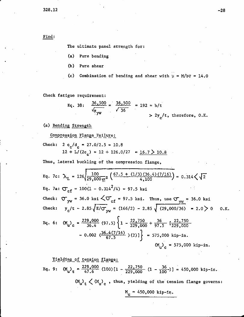
Find:
The ultimate panel strength for:
(a) Pure bending
(b) Pure shear
(c) Combination of bending and shear with ~ = M/bV = 14.0
Check fatigue requirement:
-28
> 2y/t, therefore, O.K.c·
Eq. 38:
(a) Bending Strength
36,500 = 36,500 = 192 = bit~ n6.yw
Check: 2 c /d = 27.0/2.5 = 10.8c c12 + L/{2c ) = 12 + 126.0/27 = 16.7> 10.8c
Thus, lateral buckling of the compression flange,
E 7' A. = i26 100 (67.5 + (1/3)(36.4)(7/16» = °314< T2q. c. L 29,000".2. 4,100 . • 'I ~
Eq. 7a: CJcf = 10~(1 - 0.3142/4) = 97.5 ksi
Check: \J = 36.0 ksi /0- f = 97.5 kst. Thus, use () = 36.0 ksiyw , c . ~.
Check: yc/t - 2.85 JE/(Tyw = (166/2) - 2.85 ~ (29,000/36)' = 2.0> ° O.K.
6 (M) = 229,000 (97 5) f 1 _ 22 2750 + 36 [22 2750Eq.: u c 36.4 • l 229,000 97.5 229,000
- 0.002 (36.4(7/16) )(2)]} = 575,000 kip-in.67.5
(Mu)c = 575,000 kip-in.
36(1 - 100 )] = 450,000 kip-in.
(M) <(M ) thus yielding of the tension flange governs:u t u c ' ,
M = 450,000 kip-in.u .
...

328.12 -29
Eq. 25:
Eq. 26:
(b) Shear Strength
For eX = 1.5 ') 1.0
2 3Eq. 13b: k = 8.98 + 6.18/1.5 - 2.88/1.5 = 10.88v .
Eq. 17: V = 36(36.75)//3 = 763 kips .
p J12(1 - 0.32) 36 - >.r::Eq.12: Av = 192 29.000112 n 10.88 = ~.64 v2
Eq.19c: V = 76311 + [0.9 - 0.787/(1.64) ] +~ •
u (1.64)2 J1.52 + 1.6
67.5(2.5) + (47.2)(1.75)(100 )}• 126(36.75) 36
= 763 (0.372 + 0.310 + 0.127} = 284 +237 + 97 = 618 kips
(V'l" ) (V<r) (Vf)
V = 618 kipsu
(c) Combined Shear and Bending Strength
Web Failure:
For R = -1.282 3
~ = 13.54 - 15 ..64(-1.28) + 13.32(-1.28) + 3.38(-1.28) = 48.24
flO:88Ab = 1.314(1.64) ~ 4t24 = 1.03 • 0.58<1.03(J2
Eq. 24b: cr = 36[1 - 0.615(1.03 - 0.58)1.18] = 27.4 ksicr .
For " = 1.64) J2v
Eq. 15c:
Eq. 29:
Eq. 28:
t( = 36 = 7.72 ksicr ..[3 (1.64)2
F = 14(84)(36.4)(36.75) 7~72 4229.000 27.4 = 1.9
t( = 7.72 .J<1.94)2(3 + 1.28)2 + 16 - (1 - 1.28)(1.94)
c. 2[2 + (1 + 1.28)(1.94)2]= 3.56 ksi
Eq. 22: V~c = 3.56(36.75) = 131 kips
,--------------------------------------------------_._----
328.12 -30
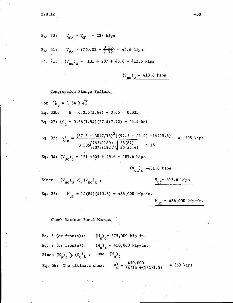
Eq. 30: VO"'c = Vc:r = 237 kips
~q. 31: Vfc = 97{0.01 + ~:~~) = 45.6 kips
"Eq. 21: {Vuc)w = 131 + 237 + 45.6 = 413.6 kips
(V ) = 413.6 kipsuc w
-For "'"A = 1.64 >f2v
Eq. 33b: B = 0.235{1.64) - 0.05 = 0.335
Eq. 27: ~ = 3.56{1.94){27.4/7.72) = 24.4 ksic
= 305 kipsV' =erc[67.5 + 30(7/16)2](97.5 - 24.4) -14(45.6)
0.33S{~~~)(i~~) ;~~~~~4) + 14
Eq. 34: (V ) = 131+305 + 45.6 = 481.6 kipsuc c .
Eq. 32:
(V ) =481.6 kipsuc c
V = 413.6 kipsuc
Eq. 35: M = 14(84)(413.6) = 486 t OOO kip-in.ucM = 486 t OOO kip-in.uc
Check Maximum Panel Moment
Eq. 6 (or from(a»: (M ) = 575 t OOO kip-in.u c .
Eq. 9 (or from{a»: (Mu)t = 450 t OOO kip-in.
Since (M) ) (M )t t use (Mu)tu c u
Eq. 36: The ultimate shear ~ - 450 t OOO 363 kiVu - 84(14 +(1/2)1.5) = ps

r---._-
328.12 -31
Since V' I V ,(363 / 413.6), the ultimate capacity of the panelu'" uc "-
under combined loads (jJ. = 14) is
V = V' = 363 kips·uc u
and (Eq. 35): M = 14(84)(363) = 427,000 kip-in.uc
M = 427,000kip~in.uc

1-----------------;------------- _
328.12
8. ACKNOWLEDGEt1ENTS
-32
This report was prepared as part of a research project on
unsymmetrical plate girders conducted in the Department of Civil Engi
neering, Fritz Engineering Laboratory, Lehigh University, Bethlehem,
Pennsylvania. Dr. David A. VanHorn is Chairman of the Department and
Dr. Lynn S. Beedle is Director of the Laboratory.
The authors express their. gratitude to the American Iron and
Steel Institute, the Pennsylvania Department of Transportation, the
Federal Highway Administration of the U. S. Department of Transportation,
and the Welding Research Council for supporting this project. They also
gratefully acknowledge the technical guidance provided by the Welded Plate
Girder Subcommittee of the Welding Research Council under the consecutive
chairmanship of Mr. M. Deuterman, E. G. Pau1et, and G. F. Fox and by the
Task Group on Unsymmetrical Plate Girders under the chairmanship of Mr.
C. A. Zwiss1er and, lately, Mr. L. H. Daniels.
r328.12
9. APPENDIX I. - REFERENCES
-33
1. Amerioan Assooiation of State Highway Offioials, Interim Speoifioations~ Highway Bridges, 1970-71, AASHO, Washington, 1971.
2. Amerioan Institute of Steel Construotion, Speoifioation for~Design, Fabrication~ Erection of Structural Steel~Buildings, AlSC, New York, 1963. .
3. Basler, K., and Thur1imann, B., "Strength of Plate Girders in Bending",Proceedings ASCE, Vol. 87, ST.7, August 1961•.
4.
5.
6.
7.
8.
10.
11.
12.
Basler, K., "Strength of Plate Girders in Shear," ProceedingsASCE, Vol. 87, ST7, october 1961.
Basler., K., "Strength of Plate Girders under Combined Bending andShear.," Proceedings ASCE, Vol. 87, ST7, October 1961.
Basler, K., Yen, B.T., Mueller, J .A., and Thurlimann, B., "Web BucklingTests on Welded Plate Girders," Welding Research Council BulletinNo. 64, New Yo~k, September 1960.
Bergfelt, A., and Hovik, J., "Thin-walled Deep Plate Girders UnderStatic Loads", Final Report of the Eighth Congress of the International Association for Bridge and Structural Engineering, heldin New York, September 1968, ETH, Zurich.
Chern, C., and Ostapenko, A., "Ultimate Strength of Plate GirdersUnder Shear", Fritz Engineering Laboratory Report No. 328.7,Lehigh University, August 1969.
Chern, C., and. Ostapenko, A., "Bending Strength of UnsymmetricalPlate Girders", Fritz Engineering Laboratory Report No. 328.8,Lehigh University, September 1970.
Chern, C., and Ostapenko, A., "UnsyInmetrical'Plate Girders underShear and Moment", Fritz Engineering Laboratory Report No.328.9,Lehigh University, October 1970.
Dimitri, J.R.,9J1d Ostapenko, A., "Pilot Tests on the Static strengthof Unsymmetrical Plate Girders", 'Welding Research CouncilBulletin No.156, New York, November 1970.
Djubek, J., "The Design Theory of Slender Webplate Bars",Stavebnicky Casopis, Sav XV, 8, Bratislava, 1967.
.....
-34328.12
13. Fujii, T., "On an Improved Theory for Dr. Basler's Theory," FinalReport of the Eighth Congress of the International Associationfor Bridge and structural. Engineering, held. in New York, .September 1968, ETH, Zurich.
14. Ostapenko, A. and Chern, C., "Strength of Longitudinally StiffenedPlate Girders under Combined Loads", Fritz Engineering LaboratoryReport No.328.l0, Lehigh University, December 1970.
15. Parsanejad, S., and Ostapenko, A., "On the Fatigue Strength of Unsymmetrical Steel Plate Girders," Welding Research CouncilBulletin No. 156, New York, November 1970.
16. Patterson, P.J., Corrado, J.A., Huang, J.S., and Yen, B.T., "Fatigueand Static Tests of Two Welded Plate Girders," Welding ResearchCouncil Bulletin No.155, New York, October 1970.
17. Rockey, K.C., and. Skaloud, M., "Influence of Flange Stiffness uponthe Load C·apaci ty of Webs in Shear," Final Report of the EighthCongress of the International Association for Bridge and StructuralEngineering, reId in New York, September 1968, ETH, Zurich.
18. Schueller, W., and Ostapenko, ·A., "Tests on a Transversely and on aLongitudinally Stiffened Unsymmetricrl.1 Plate Girder", Welding
Research Council Bulletin No.156, New York, November 1970.
19. She1estenko, L.P., Dushnitsky, V.M. and Borovikov, V., "Investigationof the Influence of Initial Web Deformations on the UltimateStrength of Welded Plate Girders", Research ~ Steel and ComnositeSuperstructures of Bridges, No.76, Transport, Moscow, 1970.(In Russian)
20. Subcommittee 1 (I~brid Beams and Girders) of the Joint ~SCE-A~SHOCommittee on Flexural Members, "Design of Hybrid Steel Beams",Proceedings ASCE, Vol. 94, ST6, June 1968.
21. Vincent, G.S., "Tentative Criteria for Load Factor Design of SteelHighway Bridges", American Iron and Steel Institute BulletinNo.15, March 1969. - -
328.12 -35
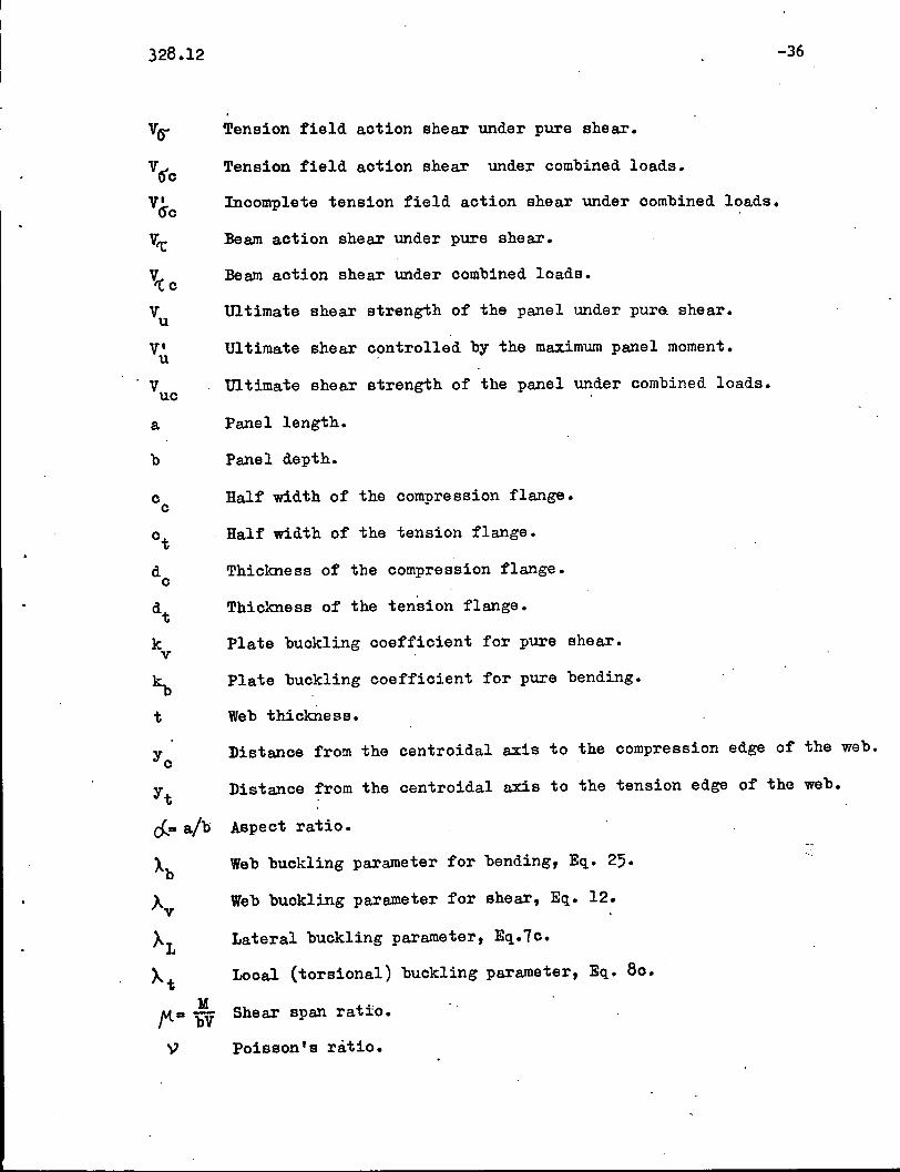
10. A:PPENDIX II. - NOTATION
B
E
F
I
I w
L
M
Mmax
Mp
Mu
Muc
MY
R
Area of the compression flange.
Area of the tension flange.
Area of the web.
Parameter defined by Eq. 33.
Modulus of elasticity (Young's modulus).
Factor defined by Eq. 29.
Moment of inertia of the girder cross section.
Moment of inertia of the compression flange about the verticalaxis.
Moment of inertia of the web about the centroidal axis ofthe whole cross section.
Unbraced length of the compression flange.
Design.moment at mid-panel.
Maximum moment in the panel.
Plastic moment of the panel.
Ultimate moment of the panel under pure bending.
Ultima te moment of the panel under combined loads.
Moment causing yielding of the tension flange.
Ratio of the maximum tensile stress (or minimum compressivestress) to the maximum compressive stress of the web (negativewhen the stress is tensile).
V Design shear at mid-panel.
Vf Frame action shear under pure shear.
Vfc Frame action shear under combined loads.
V Plastic shear of the web.p
328.12
~
~
~
~
~o
~
v'u
a
b
t
Yt
~~
Ab
Av
AL
~tM
~aW
y
-36
Tension field aotion shear under pure shear.
Tension field aotion shear under oombined loads.
Inoomplete tension field aotion shear under oombined loads.
Beam aotion shear under pure shear.
Beam aotion shear under oombined loads.
Ultimate shear strength of the panel under pur& shear.
Ultimate shear o?ntrolled by the maximum panel moment.
Ultimate shear strength of the panel under oombined loads.
Panel length.
Panel depth.
Half width of the oompression flange.
Half width of the tension flange.
Thiokness of the oompression flange.
Thiokness of the tension flange.
Plate buokling ooeffioient for pure shear.
Plate buokling ooeffioient for pure bending.
Web thiokness.
Distanoe from the oentroidal axis to the oompression edge of the web.
Distanoe from the oentroidal axis to the tension edge of the web.
Aspect ratio.
Web buokling parameter for bending, Eq. 25.
Web buokling parameter for shear, Eq. 12.
Lateral buokling parameter, Eq.70.
Looal (torsional) buokling parameter, Eq. 80.
Shear span ratio.
Poisson's ratio.
328.12
ero
Tor
-37
Bending buokling stress at the extreme oompression fiber ofthe web.
Buokling stress of the oompression flange oolumn.
Web buokling stress under pure bending.
Yield stress of the oompression flange.
Yield stress of the tension flange.
Yield stress of the web.
Shear buokling stress under oombined loads.
Shear buokling stress under pure shear.
Shear yielding stress.
328.12
Panel Cl.
I
~
);
t,,
~M ,
~ V
I
a/2 a/2-a
-(a) Panel
,, M M f\, max
- (c) Moment Diagram
Fig. 1 Plate Girder Panel With Design Loads
-38
t
Ycb
N.A. -- -Yt
(b) Cross Section

o o
WN()l).....N
J
Buckling &tren~+h '4:(eeQrn Ac.+lon)
+ J
Po~tbuc.k Itn~
stren~th Vtr
(Tens' on f\e lc\ Ac. tJ or.)
I=la n~e Stren9t~ Vf
(t=' rame Ac.tlon)
Fig. 2 Panel Strength Under Pure Shear .
w·N00
3.02.52.01.5
~cr =1-0.615(A-0.58)1.I8y
~
1.00.5
II II . I-----,----1 --
. I I I
Strain.l . I . ~ ElasticHardening i,ne,ast'i BUCkllngi Buckling
0.58
o
1.5
0.5
I~
o
Fig. 3 Buckling Strength of the Web Under ~ure Shear

(.0 - -------"-- --- - - -- - - - --
0.5- ----- - ---- - --
0.6 Ay - 0.348
0.5
J
III
-IfI
2.0 2.5 3.0
I~~
Fig. 4 Postbuckling Web Strength Under Pure Shear
I~'
N
WN'co.~N
100
••••
75 90
(27 TESTS)
", ..
. . _~~ :PROP S~D-.*,mc<r=---- - "-
IItII/
'f
I. / /,
I./1
~\l~ IfUJY Ior./
, ~ .;-/6~5~1~ ).... . . . . . . . . . .. . . . . .. . . ..,.' .... '.. / ..... , ..
.~ -----'.'
o
sotI)t--J
.' ::>U)
~40t-V)llJ.....~JOoff~
'0 't:: 20S~
luQ
~/O0;
Fig. 5 Comparison of Design Equations With Barsler's and Fujii's Metho~s

WN00.....N
Tension Field Action
({±---;Q )
'jD~l. ---
+.
I r~_.
~ ~.
~-
o
vVu
Q.. Frame Action
1.0
Fig. 6 Schematic Interaction Diagram and Failure Modes

o~---------o
wl\,)
00.
1'c
'c-
~ig. 7 Web Stresses Under Combined Loads
o .00.J-__L-_..L_..l-__-l- + -'- -'- _
Fig. 8 Derivation of Parameter B (Combined Loads)

•
WN00.I-'N
Shear Strength Reducedby Bending (Web ~ailure)
MM
u1.0
~Bending Strength Reduced, . by Shear (Compr. Flange
Failure)
(Q---B)
vv
u
\ If---OQ)-1.0
Flange Yielding
M M-.E. J..M M
u u
Plastification
Fig. 9 Design Interaction Diagram
........
328.12 -47'
..
•
- l.
•
- . ,compute. No Y'\- ~iMev\"\:i0\'\0..\ ?o..ro..m.e.-te Y"~
0<. # b/-l:, o.'l'\~ ';c./t:I
"I I
IC:orY\~""e.~~\O'l'\ F\o.'i\~e Fo..du'f"e.1 "'Te.V\~\oY'l ~\a..",~Q.
~",ie.\ cb",~
I . I-IlQ,lca.'l"~\ 'P,;)"'c:.\<..\\V\~ I l~o'C"$\o"G.\ ~u.c.\c.\i"c:\ I
I
I AL ('=,. ; e )1 I~l (~,. ~c.) II
Itr"c+ (£:~. ~o. Or b) IA I It1C:+ (EC:\. 80. or 'b) IB II I
I
tP->~\'\~iYl15b"e"'\\:h (tI\\l)c: ""u. eQ.~!·\Y\~ ~~'l"en~th (Mu\~ Mu..(=,. IS) (:E~. C\)I I
I~e.",d'n~ S\: 'C" e "~~h Mu \":> \:h e. ~'MQ,.\\eV' C
o~ O""")c. 0..01\ ~ (\-!\\\)\:
(a) Bending Strength
Co 0",", ~\),te. Doe.. o.Y\.6 kv l t:~. \2:»)
I
(b) Shear Str"ength
Note I Letters A, ~, C, D and E designate operations the results ofwhioh are also used in Fig. 11.
Fig. 10 Computational Sequenoe for Bending and Shear Strengths
......
328.12 -4a .
••,
•
fompute non-dimensional parameter4~ , bit, R(Fig. 7)I
ky (Eq. 13 or Operation D of Fig.10b){Che ck MaximumIAy (Eq.12 or Operation E of Fig.lOb) Panel Moment
I~r (Eq.15')1
I~ (Eq.26) I: I
lAb (Eq.25) 1 }Mu,from Operation C inl
Io-cr (Eq • 24)Fig. lOa
IfF (Eq. 29)
I
I~ (Eq. 28)
IBeam Action Shear V't;'c (Eq. 22) I
, IIVf (Eq. 18)1 Shear Strength
I V' (Eq. 36)uFrame Action Shear for Combined Loads
Vfc (Eq. 31)
II
Icompression Flange/ IWeb FailureIFailure -
I~f from Operation A or Bl
of Fi~. lOaJ
B (Eq. 33)1I
~ (Eq. 27)1:I
Inoomplete Tension Field Tension Field ActionAotion Shear V~c (Eq.3~)10--- Shear V(fC (Eq.16) .
"Shear Strength Shear Strength(Vuc)c (Eq.34) (Vuo)w (Eq.2l)
I JI
Ultimate Shear Strength V is thesmaller of (V) (V '0 and V'.uc c' uc w u
Fig. 11 Computational Sequence for Combination of Bending and Shear
P. ',' ...... ,.
DATE DUE
1i-t.w3J1'46"IB
Wtl /320'1.1 UA.B
VIAe: 1/2$"'/07-
,
•••
•