Embed Size (px)
Citation preview

26 | P a g e
University of South Florida Energy Delivery Infrastructures
PI: Lee Stefanakos Co-PIs: Zhixin Miao Students: L. Piyasinghe (Ph.D.), L. Xu (Ph.D.), M. Alhaider (Ph.D.) Description: The purpose of the project is to simulate the effects of a renewable energy generation system (renewable energy distributed generation and a battery system), in a micro-grid, on the distribution grid system during critical conditions such as power peaks. Existing simulation tools can be used to properly represent dynamic and transient behaviors of microgrids. Budget: $485,184 Universities: USF Project Summary This project report summarizes three on-going tasks: 1) Microgrid power management scheme analysis; 2) Control and operation of a battery system in a microgrid; and 3) Impacts of pulse power loads on a microgrid. Microgrid power management scheme analysis: With the increasing use of renewable energy resources and energy storage devices, inverter-based distributed energy resources (DERs) become the important components in microgrids. As diesel generators with direct ac connections are the current most cost effective and reliable power sources, the stability investigation of microgrids should include both types of DERs. In this project, dynamics of diesel generation are included and the interaction of the diesel generators and the inverter-based DERs will be investigated using eigenvalue analyses and time-domain simulations. The significant contributions of this research include: 1) identification of the stability problem in microgrids with inverter-based DERs and conventional generators, and 2) investigation of the interaction problem of inverter-based DERs and conventional generators in islanded microgrids.. Control and operation of a battery system in a microgrid: the objective of this task is to investigate the control strategies of a Li-Ion battery group with a PV array within a microgrid. At the grid-connected mode, the battery and the PV array operate at power control mode, while at the autonomous mode the battery provides voltage and frequency control instead. The contributions of this work include: (i) a detailed model of a battery pack, including state of charge (SOC), short-time and long-time transient characteristics and a detailed model of a PV array have been built; and (ii) effective control strategies for a battery with the PV array system to operate at both the grid-connected and the autonomous modes have been developed. A test microgrid consisting of a voltage source converter (VSC) interfaced battery, a PV array, passive loads and an induction machine is built in PSCAD/EMTDC. Simulations have been carried out and demonstrate that the proposed control strategies could coordinate independent distributed generation effectively.. Impacts of pulse power loads on a microgrid: the main objective of this task is to investigate the pulse power load (PPL) impact on the stability of a microgrid with power electronic converters. The PPLs are largely employed in areas of high power radars, lasers, high energy physics experiments and weapon systems such as rail guns. The peak power of a pulse load can vary from several hundred kilowatts to several hundred megawatts and the time duration is typically from microseconds to seconds. Hence for the proposed work, a microgrid with Voltage Source Converter (VSC) based inverters and synchronous generators are considered in order to provide a better approach towards the smart grid. The study is conducted in PSCAD/EMTDC and Matlab/SimPowersystems.

27 | P a g e
Microgrid power management scheme analysis
Stability analysis of a microgrid is carried out in [1]. The system consists of diesel generators with direct ac connections, which are the current most cost effective and reliable power sources, and VSC converter interfaced DERs. Those DERs could be fuel cells. Stability investigation for the hybrid systems has not been addressed in the previous literature. The research work models the dynamics of diesel generation and converter control loops in a da reference frame. The interaction of the diesel generators and the inverter-based DERs is investigated using eigenvalue analysis and time-domain simulations. The significant contributions of [1] include: (i) identification of the stability problem in microgrids with both inverter-based DERs and conventional generators and (ii) investigation of the interaction problem of inverter-based DERs and conventional generators in islanded microgrids. The study system is shown in Fig. 1. The system is built based on the benchmark system of IEEE standard 399-1997. Two diesel engine generators and two converter-interfaced DERs form a microgrid. Under islanded conditions, the breaker connected to the utility is open. Effect of f-P droop on dominating system modes The root locus of a changing f − P droop gain in one of the inverter-based DERs is shown in Fig. 2. From the root locus diagram in Fig. 2, it is found that the gain of the f − P droops in the inverter-based DERs do not impact the system stability significantly. Rather, the gain of the f − P droop in the diesel engine impacts system stability significantly. A larger gain means more participation in load sharing. In Fig. 2, it is noted that the larger the gain, or the more the diesel engines participate into load sharing, the more unstable the microgrid becomes. Therefore, the diesel generators should have a limited gain. This results in an insignificant participation in load sharing. Fig. 3 shows the dynamic response of the four DERs due to a load change. The simulation results corroborates with the analysis.
Fig. 1 Study system

28 | P a g e
Fig. 2 Root locus diagrams with a changing f-P droop gain in DER3.
Fig. 3. Dynamic performance of the four DERs due to a load change.
Publications & Conferences 1. Z. Miao, A. Domijan, and L. Fan, “Investigation of Microgrids with Both Inverter Interfaced and
Direct AC Connected Distributed Energy Resources,” IEEE Trans. Power Delivery, vol. 26, no. 3, pp. 1634-1642, July 2011.
2. L. Xu, Z. Miao and L. Fan, “Control of a back-to-back VSC system from grid-connected to islanded mode in microgrids,” in Proc. of IEEE Energy Tech, May 2011
3. Z. Miao, A. Domijan, and L. Fan, “Negative Sequence Compensation for Unbalance in Distributed Energy Resources Interfacing Inverters,” International Journal of Power and Energy Systems, no. 3, 2012.
4. L. Fan, Z. Miao, and A. Domijan, “Impact of Unbalanced Grid Conditions on PV Systems,” IEEE Power & Energy Society General Meeting 2010.
Control and operation of a battery system in a microgrid. The objective of this research is to study the control strategies for a microgrid with both a battery group and a PV array. The study approach is detailed model based simulation. Detailed battery models have been developed both by mathematic equations and electrical circuits. A Li-ion battery model is using electrical components, which was validated through experiments. PV model has been investigated thoroughly in the literature. The current source and anti-parallel diode model has been proved to be able to simulate the V-I characteristics of a solar cell accurately. For the PV and battery combined systems, a power management mechanism that could optimize the power flow. Utilize batteries to reduce the fluctuations of PV output. The power within PV and battery system can be scheduled from the power system’s point of view. Besides the PV and battery combined system, PV and capacitor combined system is also examined by other researchers. Capacitors are also could be used to reduce the power fluctuation of PV, or participate in frequency control.

29 | P a g e
The focus of this task is control strategies at the autonomous mode. We have conducted research on developing battery operating strategies based on a detailed battery model at both the grid-connected and the autonomous mode. The research is expanded to include a PV array in the microgrid. Coordination among different DERs will be taken into consideration. The microgrid studied in this paper consists of three distributed energy resources (DERs). An induction machine driven by a diesel engine works at the generating mode. It supplies active power to the loads within microgrid. A PV array is connected to the microgrid and supports the loads as well. A VSC interfaced battery station is included to store excess energy from the PV array or inject energy when there is a need. Fig. 4 shows the topology of the investigated microgrid where three distribution lines are used to connect each component. The topology complies with the IEEE Standard 399-1997.
FIGURE 4. STUDY SYSTEM OF TASK 2 Figure 5 shows the power coordination mechanism of the PV and the battery system. The AC grid voltage and frequency are the variables to be controlled. The output real power and reactive power of the battery system are dependent on the measured frequency error and voltage error. The total output power from the PV and the battery should meet the requirements of the microgrid.
Figure 5. Coordinated control strategy of PV and battery system at autonomous mode in Task 2.
Publications & Conferences 1. L. Xu, Z. Miao and L. Fan, “Control of a battery system to improve operation of a microgrid,”
IEEE PES General Meeting, 2012.
Line 1Load 1
IM
Load 2
Line 2
Load 3
AC
DC
GridTransformer 1
Transformer 2
A
PCCBattery
Line 3
AC
DC
PVDC
DCTransformer 3
Line 4
PV+Battery System
PV
PBattery
MPPT
+
Ppv
QBattery
+Qpv
P, Q from PV-
Battery System
+
+
Battery with vf control

30 | P a g e
2. L. Xu, Z. Miao and L. Fan, “Coordinated Control of a Solar and Battery System in a Microgrid,” IEEE T&D meeting, 2012.
Impacts of pulse power loads on a microgrid The objective is to investigate the pulse power load (PPL) impact on the stability of a microgrid with power electronic converters. The PPLs are largely employed in areas of high power radars, lasers, high energy physics experiments and weapon systems such as rail guns. The peak power of a pulse load can vary from several hundred kilowatts to several hundred megawatts and the time duration is typically from microseconds to seconds. Hence for the proposed work, a microgrid with Voltage Source Converter (VSC) based inverters and synchronous generators are considered in order to provide better approach towards the smart grid. The study is conducted in PSCAD/EMTDC and Matlab/SimPowersystems. The reported work considers the impact of a PPL load on system voltage profile only. But for the proposed Task 3, the impact on both voltage and the frequency of the microgrid system is considered. The study of the microgrid system to evaluate the impacts of PPL is shown in Fig. 6.
Figure 6. Study Micogrid System in Task 3 PPL can be connected to a microgrid either directly or through a storage element. For the proposed work PPL connected through a capacitor is considered since the system is unable to provide the peak load of the PPL without losing stability. The PPL model consists of a three phase rectifier , filter circuit and buck converter.
Publications & Conferences 1. L. Piyasinghe, and Z. Miao, “Investigation of the Microgrid Operation with Pulsed Power
Loads,” Technology and Innovation (accepted).
G
GS
Utility System
L1
L2
DG1
DG2
DG3
PPL
DG1,DG3 - Synchronous GeneratorsDG2, DG4 - DERsPPL - Pulsed Power Load
PCC
13.8 kV
230 kV
9 MW.5 MVar
12 MW1.6 MVar
Inv
L3
DG4
Inv

31 | P a g e
University of South Florida Energy Efficient Technologies and the Zero Energy Home Learning Center
PI: Stanley Russell Co-PI: Yogi Goswami Students: Mario Rodriguez (MA), Sean Smith (MA), Jon Brannon (MA), Jean Frederic Monod (MA) Description: The project is to create and evaluate an affordable residential scale Zero Energy building that will function as an exhibition of energy efficiency and Zero Energy Home [ZEH] technology on the University of South Florida campus. The project will feature the most cost-effective combination of renewable solar energy with high levels of building energy efficiency. The building will incorporate a carefully chosen package of the latest energy efficiency technologies and renewable energy systems to achieve the most successful and reliable results. The building will utilize Photovoltaic solar electricity and solar domestic hot water heating systems using the grid as an energy storage system, producing more energy than needed during the day and relying on the grid at night. Plug-in hybrid automobile technology offers a promising means of providing distributed energy storage for such homes. Using a systems approach to couple zero energy home technology with PHEVs we will explore opportunities to develop marketable products that meet Florida’s energy and environmental goals. Budget: $344,600 Universities: USF-School of architecture, College of Engineering, College of Mass Communications, School of Business FSU-College of Engineering UF- Department of Interior Design UF-Rinker School of Building Construction UCF-Florida Solar Energy Center External Collaborators: Palm Harbor Homes Beck Construction Hees and Associates Structural Engineers Progress Summary Before beginning design on the ZEH Learning Center we studied vernacular precedents and more recent building and research projects that have aimed at zero energy or near zero energy status. We looked at Vernacular Florida architecture as precedent for passive cooling, heating and daylighting. Building design in Florida changed considerably with advancements in mechanical systems in the mid- 20th century. Up until that time houses typically had wide overhangs to shade the walls and windows, wide covered porches for outdoor living and high ceilings with crawlspaces under the floor to induce natural ventilation. After air conditioning became popular houses were built to close out the heat with smaller windows, compartmentalized interiors, and low flat ceilings. Passive solar design was experimented with during the energy crisis of the 1970s and although it was mostly applied to cold climates, many of the lessons learned during that period are once again relevant in the current movement toward zero energy buildings.

32 | P a g e
Because the thermal comfort range of the average American has changed since the proliferation of air conditioning, it would be difficult for most to live in a passively cooled home especially in Southern Florida. Regardless, the principles of vernacular buildings and passive solar design can complement advances in highly efficient mechanical systems to greatly reduce the energy consumption of buildings. There is also evidence that comfort levels can be gradually altered when standards are placed on heating and cooling levels in buildings. South Korea for example, has set a standard of not less than 26c [79f] in the summer for air conditioning and not more than 20c [68f] in the winter for heating in public buildings. In Japan, air conditioning in public buildings is mandated at not less than 28 [82f] degrees in the summer season. Many of the examples of near zero and zero energy houses in Florida are projects implemented by The Florida Solar Energy Center® (FSEC), a research institute of the University of Central Florida. Since 1998 with funding from the department of energy’s building America program FSEC has built and monitored several zero energy and near zero energy houses in the State of Florida. Data gathered from monitoring the performance of these houses is a valuable resource for ZEH research. The FSEC projects made it clear that combining energy efficiency in building design and appliances with PV and solar thermal systems for clean renewable energy generation can result in affordable zero energy houses. The Off Grid Zero Energy Building [OGZEB] at Florida state university is an off grid zero energy test house which is just beginning to yield data. In addition to Photovoltaic panels, the OGZEB incorporates hydrogen fuel cells for storage and production of electric power. The Florida House Learning Center in Sarasota Florida, like the proposed ZEH Learning Center, was established to showcase sustainable building technologies to builders and the general public. The Florida House contains exhibits of various green building products and the building itself has explanatory text in various locations to describe the technologies at use. I traveled to Japan in June and met with engineers at two of Japan’s largest housing manufacturers Misawa Homes and Sekisui Haimu. Misawa Homes produced its first Zero Energy House Model in 1998 and since then has sold thousands throughout Japan. Both companies take a systems approach to life cycle cost, energy use and CO2 emissions with their highly efficient manufacturing processes. The experience in Japan made the advantages of factory built homes evident and led us to pursue a housing manufacturer as an industry partner. In addition to documenting what has already been accomplished in the field of building energy efficiency we also feel that it is important to know about the emerging technologies that will transform Zero Energy Building design in the near future. Some of these are already beyond the testing stage and in commercial production but are expensive compared to more conventional alternatives. This is often a function of supply and demand and in many cases it can be assumed that an increased demand for these products will lead to lower prices. We think that raising public awareness to increase demand for quality products is one important function of the Zero Energy House Learning Center. Technologies like Aerogel insulation, vacuumed insulated glass, electro-chromic glass, building integrated photovoltaic materials and OLED lighting will revolutionize building design and construction when they reach an affordable level. Liquid desiccant cooling and dehumidification show promise for the next generation ZEH in the hot and humid southeast. Liquid Desiccant solar cooling systems developed as part of the Department of Energy’s SBIR program convert hot water from solar thermal panels into cooling and dehumidification. We are also interested in the interface between the ZEHLC and other related systems. The key to energy efficiency in the future will undoubtedly lie in smart grids that will regulate the flow of electricity to and from buildings according to peak and low demand periods. The plug-in hybrid electric vehicles, soon to be released by several auto makers, will be key elements in regulating this flow and storing energy for the grid and will be considered as an integral part of the ZEHLC design.

33 | P a g e
The Solar Decathlon is an event held every other year on the Mall in Washington DC to showcase the latest advances and emerging technologies for energy efficient buildings. 20 Teams are chosen from an international pool of applicants to design and build energy efficient buildings on the Mall. In answer to the RFP for the 2011 Solar Decathlon I assembled a team of experts from FSU, UF, UCF and USF in the fall of 2009 to make a proposal. Our proposal was deemed competitive in January 2010 and we were asked to submit a schematic design proposal by March of 2010. Based on the strength of our submission, Team Florida was chosen as one of 20 teams to compete in the 2011 Solar Decathlon. Participation in the 2011 Solar Decathlon expands the potential of the ZEHLC as a learning tool and facilitates additional funding and input from experts across the state. Based on our research from the first year we began looking at architectural and engineering innovations that could improve on current ZEH technology and construction practices. The closed nature of recent Florida houses and early attempts at ZEH was identified as a problem that we wanted to address with the ZEHLC. We maintain that contemporary Florida houses can significantly reduce their annual energy consumption by incorporating the same passive solar strategies that were commonly used in Florida homes before the advent of air conditioning. A building envelope that is well sealed and insulated and can be opened during the cooler/dryer months of the year and closed when temperature and humidity levels are too high, can have a more open feeling and save energy at the same time. Furthermore, studies at FSEC have shown that the majority of heat gain comes through the roof of Florida homes and attic spaces reach extremely high temperatures in the range of 1400. We considered the use of a shading device that would cover the entire roof and east and west walls of the house to significantly reduce or eliminate direct solar radiation coming in contact with the building envelope. A ventilated space between the shading device and the house would prevent the buildup of hot air that commonly occurs in the attic space of Florida houses. According to a life cycle assessment of energy use, we looked at a modular, factory built house to minimize construction waste and maximize efficiency in labor and energy use during the construction process. Innovative mechanical systems including a liquid desiccant system for controlling humidity levels and reducing latent heat load; a solar thermal system that takes advantage of a high thermal conversion of solar radiation and uses it for a variety of energy end uses and a heat pump tied to the solar thermal system to increase efficiency in both systems. To test the effectiveness of different building envelope alternatives, we built 3- 8'x8'x8’ structural insulated panel modules, each with a different envelope system. Module 1, the control case, had no additional treatment of the envelope. Module 2 had a 3/4" ventilated airspace on the exterior skin of the roof and walls. Module 3 had a shading device covering the roof and east and west walls. Fig. 1 module construction Fig. 2 module 2 complete Fig. 3 testing module 3 The 3 modules were monitored under identical conditions simultaneously over an 8 hour period with a Campbell Scientific PS100 Data logger and 3 temperature and relative humidity sensors attached to

34 | P a g e
determine the most efficient and economical configuration of the building envelope. The results confirmed that the module with the shading device had the lowest interior temperature at the end of the 10 hour period. The temperature difference within the modules continued to grow as the hours passed and the insolation continued to raise the temperature disproportionately in the unprotected module 1. Fig.4 black line is module 1, blue line is module 2, green line is module 3 We applied our research from the first 11/2 years of the grant period to our schematic design concept. Based on our research we were convinced that contemporary houses can significantly reduce their annual energy consumption by incorporating passive solar strategies. We decided on a hybrid approach to the building envelope combining current thinking in ZEH technology with vernacular wisdom with an envelope that can be opened during the cooler/dryer months of the year and naturally ventilated and closed and mechanically cooled when the outdoor temperature and humidity levels are too high to achieve an acceptable comfort range by natural ventilation. The entire north elevation is sliding glass panels that can be opened to the garden to allow natural ventilation and a sense of connection with the landscape promoting a healthy and energy efficient indoor/outdoor Florida lifestyle. On the south elevation all of the glass is shaded by louvers to eliminate insolation during most of the year. During winter when the sun is lowest in the sky there are typically several cold days when afternoon temperatures are low enough to require space heating. Louvers on the south side of the building will be adjustable so that the sun can be allowed to penetrate the space on cold days but can also shade the sun on warm winter afternoons. A shading structure made of steel tubing and wood lovers will completely shade the roof and east and west walls of the house stopping the hot solar rays from radiating through the building envelope. An 18” space separating the shading device and the building will allow air to pass through freely and prevent the buildup of hot air between the two. The umbrella will also support the PV array and solar thermal panels making them easily accessible without disturbing the building envelope. The house is designed for pre fabrication to minimize construction waste and maximize efficiency in labor and energy use during the construction process. Since we plan to ship the house in one piece the exterior dimensions are limited by shipping restrictions. Portions of the building that go beyond the prescribed shipping width are designed to telescope out from the main building envelope making the house economical to ship and quickly deployable at the site. A 5 KW PV array will provide electric power to the house; a liquid desiccant system will control humidity levels and reduce latent heat load; a solar thermal system that takes

35 | P a g e
advantage of Florida’s high thermal conversion of solar radiation will be used for space heating, hot water and to regenerate the liquid desiccants. Hot and chilled water will be circulated around the house to fan coil units in 3 zones for localized control of temperatures and reduced temperature fluctuations when compared to forced air systems. Design Development was completed in November of 2010 complete with a BIM model of the building a detailed half inch scale model and a digital animated walk thru. The scale models were exhibited at the International builder’s show in Orlando in January 2011. A 70 page set of Construction Documents was completed in March of 2011 and a contract between Beck Construction and USF was finalized for the construction of FLeX House. After delays in the contract process, construction began in mid-May, 2 months behind the original schedule. Construction continued through the summer and was completed in early September. The house was disassembled and shipped to Washington DC where it was successfully reassembled in West Potomac Park and exhibited in the 2011 Solar Decathlon. Tens of thousands flocked to the popular house which was second in total attendance among the 19 houses on display. The Solar Decathlon gave students the opportunity to tour the other 18 houses and exchange ideas with their peers as well as explain their ideas to the thousands of visitors to the house. The 3 week event was an exceptionally intense and rich learning experience for the students involved. The house was disassembled and shipped back to Tampa where it was planned to become an exhibition of energy efficient technologies and a laboratory for energy efficiency research on the USF campus. However it was decided that the cost of setting up and maintaining the house on campus would exceed its potential research benefits and the house is currently in storage. Talks are underway with potential future owners of the house. Funds leveraged/new partnerships created
New collaborations Florida Power and Light TECO OUC Progress Energy USF COE UCF Wells Fargo CSI Solar World Bosch Sothern Cypress Manufacturers Simpson Strongtie Kohler Dupont Pella, CWS Lithonia Beck Construction
Sponsor Sponsor Sponsor Sponsor Sponsor Sponsor Sponsor Sponsor Sponsor Sponsor Sponsor Sponsor Sponsor Sponsor Sponsor Sponsor Industry Partner
$10,000 $10,000 $10,000 $10,000 $20,000 $16,000 $15,000 $500 Gift in Kind Gift in Kind Gift in Kind Gift in Kind Gift in Kind Gift in Kind Gift in Kind Gift in Kind
Proposals Title 2011 Solar Decathlon
Agency DOE
Reference Number
PI, Co-investigators and collaborators Stanley Russell
Funding requested $100,000
Project time frame 8/2010
Date submitted 12/2011

36 | P a g e
Technology Fee Grant
USF
Stanley Russell Mark Weston Yogi Goswami
$223,462 1 year
3/15/2011
Grants Awarded
Title 2011 Solar Decathlon
Agency DOE
Reference Number
PI, Co-investigators and collaborators Stanley Russell
Period of Performance 16 months
Funding awarded $100,000
ZEHLC research has been presented at the following conferences and meetings: Russell S.R., Reaching Zero Energy in Florida’s Hot Humid Climate, ARCC 2011 CONSIDERING RESEARCH: Reflecting upon current themes in Architectural Research, Detroit MI, spring 2011, Russell S.R., Weston M., Goswami Y., Doll M. Flex House, ASME 2011 5th International Conference on Energy Sustainability & 9th Fuel Cell Science, Engineering and Technology Conference, Washington D.C. Summer 2011 Russell S.R. Energy Efficiency and the Zero Energy Home Learning Center, ACSA National Conference, RE.building, New Orleans Louisiana, Spring 2010 Russell S.R. Evolution of the American Zero Energy House, Eco-Architecture 2010, La Coruna Spain, Spring 2010 Russell S.R. Evolution of the American Zero Energy House, International Conference On Building Science And Engineering, Johor Bahru, Malaysia, December 2009 Eco House Symposium- Kanagawa University, Kanagawa Japan- summer 2011 AIA Florida Annual Conference- Naples Florida- summer 2011 ASME Tampa Bay Annual Meeting- FLeX House- summer 2011 AIA Tampa Bay Designer’s Luncheon Lecture Series- fall 2010- 2011 Solar Decathlon - FLeX House CSI Luncheon - FLeX House- spring 2011 ZEHLC research has been published in the following journals: Russell S.R. Hybrid ZEH for Florida’s Hot Humid Climate, The International Journal of Design & Nature and Ecodynamics, WIT Press.

37 | P a g e
The ZEHLC design model has been exhibited at the following venues: Title- U.S. Department of Energy Solar Decathlon 2011 Finalists: A Special Presentation, Venue- National Building Museum, Washington DC Date- 5/ 1- 7/25, 2010 Title- U.S. Department of Energy Solar Decathlon Venue- Orange County Convention Center Date- 1/12-1/15, 2011 Title- U.S. Department of Energy Solar Decathlon Venue- McCormick Place Chicago IL. Date- 1/12-1/15, 2011 Title- U.S. Department of Energy Solar Decathlon 2011 Finalists Venue- Portland Downtown Marriot Waterfront, Portland, Oregon Date- 8/11-8/14, 2010 Title- U.S. Department of Energy Solar Decathlon 2011 Finalists Venue- National Renewable Energy Laboratory Visitor Center Date- April 2010 Title- Zero Energy House Learning Center Venue- ASCA National Conference Poster Session, Montreal, Canada Date- 3/ 2011 We applied for and received a $100,000 from the DOE for the 2011 Solar Decathlon. Our team raised $55,000 in cash donations and an additional $75,000 in gifts in kind.

38 | P a g e
University of South Florida Feasibility, Sustainability and Economic Analysis of Solar Assisted Biomass
Conversion PI: B. Joseph Co-PI: Q. Zhang Students: Matt Wetherington (BSChE), Maria Pinilla (MS, Civil and Environmental Engineering), Chita Yang (PhD in Chem. Engg.) Description: The main deterrent for commercialization of biomass conversion processes is the cost of conversion; particularly the need to sacrifice as much as 30% of the energy content in the biomass for the thermo chemical conversion step. We want to research and develop the concept to use solar thermal energy from concentrating units to provide energy for the biomass gasification step. We also propose to evaluate the sustainability of such a process. Overall Objective: The overall objective is to conduct a theoretical analysis of solar assisted thermo chemical conversion of biomass from the point of view of energy efficiency, economic feasibility, environmental impact, and long term sustainability of renewable energy production. Budget: $45,238 Universities: USF Funds leveraged or new partnerships created. Partnerships were created with faculty in the Civil and Environmental Engineering and faculty at UF to submit a NSF EFRI proposal on Sustainable Microalgae Bioenergy Systems. Partnerships were created with UF (College of Agriculture), NREL, ORNL, and US Forest Service to submit a proposal to the BRDI (Biomass Research and Development Initiative) program run jointly by DOE and DOA. Progress Summary Overall Objective: The overall objective is to conduct a theoretical analysis of thermo chemical conversion of biomass with and without solar energy from the point of view of energy efficiency, economic feasibility, environmental impact, and long term sustainability of renewable energy production. We completed process design and economic analysis of the thermochemical conversion of biomass to liquids with and without solar energy. The results are included in the 2012 Annual Report below. It was found that the capital cost of the solar energy collection system is a significant factor in the economics of the process. The cost of solar thermal systems will have to be significantly reduced before solar assisted biomass gasification can become feasible. Based on economic analysis, the goal of LCA has been shifted to compare different feedstocks and processes because solar assisted biomass conversion is not economically feasible. In this study, a comparative LCA has been developed to evaluate the environmental impacts associated with different energy products via different routes across the whole life of algal and lignocellulosic bioenergy. Results were compared per energy basis, the production of 1 million BTU of energy products. It was found that cultivated algae biomass feedstock has much higher environmental impacts compared with lignocellulosic biomass feedstock from forestation and agriculture byproducts. It was also concluded that thermochemical gasification and FTS process showed higher efficiency when converting biomass to bioenergy.

39 | P a g e
2012 Annual Report The objective for this FESC project was to conduct a theoretical analysis of solar assisted thermochemical conversion of biomass from the point of view of energy efficiency, economic feasibility, environmental impact, and long term sustainability of renewable energy production. The specific objectives for our group are to evaluate the design, economic feasibility and environmental impacts and long term sustainability of solar assisted biomass conversion and identify the opportunities for technological improvement. To achieve the above objectives, two different systems will be compared: (1) biomass conversion without solar unit and (2) solar assisted biomass conversion. The first case is based on an NREL study which looked at the feasibility of producing mixed alcohols from biomass. NREL report outlines the general process design and economics for this process. This process was modified to produce hydrocarbon fuels by changing the catalyst used in the Fischer-Tropsch Synthesis step. In the second case we decided to investigate the economic feasibility of a “power tower” gasification approach in which a gasifier would be housed in the central receiver of a 150 meter tall tower that would be directly heated by heliostats (mirrors) to reach temperatures in excess of 1800F. The tower would have roughly 500-600 acres of heliostats associated with it to provide the energy needed for gasification. The heliostats would focus the suns energy to the top of the tower which will then heat the gasifiers to 1800F. The capital investments for the solar technologies in this case were estimated at $120 million. This adds significantly to the overall cost of the biomass liquefaction system. This type of gasification will require much R&D to be successful. The technology for central receiving solar power tower heat generation is not new, and is a proven, but not yet fully embraced, as a way of producing electricity. The strategic placement of the mirrors around the tower can create very serious logistical problems in regards to land usage within the plant, and should be worked out carefully. The main goal in the design of the central receiver is to provide the thermal fluxes needed for indirect steam gasification. A process design using the NREL report as a basis was completed and the results indicate that the solar assisted conversion costs significantly more based on the current estimates of the costs of solar concentrating units. As the costs of the parabolic troughs used for solar energy conversion is reduced ( mass production will lower costs) the use of solar energy to assist the gasification step will become more economical. The following figure shows the capital cost breakdown for a solar assisted plant.

40 | P a g e
Life Cycle Analysis Based on the above economic analysis, the goal of LCA has been shifted to compare different feedstocks and processes because solar assisted biomass conversion is not economically feasible. Lignocellulosic and algae biomass have been evaluated as promising feedstocks for bioenergy production. In this study, a comparative LCA has been developed to evaluate the environmental impacts associated with different energy products via different routes across the whole life of algal and lignocellulosic bioenergy. Results were compared per energy basis, the production of 1 million BTU of energy products. For the development of the comparative algae biomass conversion LCA, algal biomass was converted to liquid biofuels via a thermochemical gasification and Fischer-Tropsch Synthesis (FTS) process; and to electricity and heat via anaerobic digestion and combined heat and power (CHP) process. Results from the algae biomass conversion LCA (Figure 2) showed that the process that converts algae biomass through anaerobic digestion and CHP process to electricity and heat had the highest overall environmental impact. Results also showed that the impact categories that appear to contribute the most to the overall impacts are ecotoxicity, human health non-cancer, and human health cancer.

41 | P a g e
Figure 2. Results from the comparative algae biomass conversion LCA. (TG: thermochemical gasification; and AD: anaerobic digestion; 1S: Wastewater is used as a source of nutrients and flue gas is used as a source of CO2, assuming the process is co-located with a power plant; 2S: Fertilizers are used as a source of nutrients, and Flue Gas is used as a source of CO2; 3S: Wastewater is used as a source of nutrients, and chemical CO2 is used as the carbon source; 4S: Fertilizers are used as a source of nutrients, and chemical CO2 is used as the carbon source.) For the development of the comparative lignocellulosic biomass conversion LCA, lignocellulosic biomass was converted to ethanol and higher alcohols through thermochemical gasification and alcohol synthesis process (process 1), to liquid biofuels via thermochemical gasification and FTS process (process 2), and to liquid biofuels via a thermochemical gasification and FTS process that uses methane (process 3). Results from the lignocellulosic biomass conversion LCA (Figure 3) showed that the process that converts lignocellulosic biomass into alcohols has the highest overall environmental impact. Results also showed that the impact categories that appear to contribute the most to the overall impacts are ecotoxicity, human health non-cancer, human health cancer, and global warming.
Figure 3. Results from the comparative lignocellulosic biomass conversion LCA. This study determined that cultivated algae biomass feedstock has much higher environmental impacts compared with lignocellulosic biomass feedstock from forestation and agriculture byproducts as shown in

42 | P a g e
Figure 4. It was also concluded that thermochemical gasification and FTS process showed higher efficiency when converting biomass to bioenergy (see Figures 5 and 6).
Figure 4. Results for comparative analysis on feedstock type
Figure 5. Comparison of algae biomass conversion technologies when producing 1 BTU algae biomass-derived energy. (Technology A: anaerobic digestion and combined heat and power (CHP) process; Technology B: thermochemical gasification and Fischer-Tropsch Synthesis)

43 | P a g e
Figure 6. Comparison of lignocellulosic biomass conversion technologies when producing 1 BTU algae biomass-derived energy. (Technology C: thermochemical gasification and alcohol synthesis process; Technology D: thermochemical gasification and FTS process; Technology E: thermochemical gasification and FTS process that uses methane) Publications, presentations, patents, licenses, industry interactions, etc. • Pinilla, M., Q. Zhang, and B. Joseph, Comparative life cycle assessment (LCA) of lignocellulosic
biomass conversion into different energy products, 2011 FESC Summit, Gainesville, FL, Sept 27-28, 2011. (oral presentation)
• Pinilla, M., Q. Zhang, and B. Joseph, Comparative life cycle assessment (LCA) of biofuels and electricity production from algal biomass, 2011 FESC Summit, Gainesville, FL, Sept 27-28, 2011. (poster presentation)
• Obregón, M. J. P., B. Joseph, and Q. Zhang, Life Cycle Assessment of Algae Biomass Conversion to Various Energy Products through Different Pathways. In preparation
• Obregón, M. J. P., B. Joseph, and Q. Zhang, Comparative Life Cycle Assessment of Lignocellulosic Biomass Conversion to Various Energy Products through Different Pathways. In preparation
• Matt Wetherington and Babu Joseph . Cost Models for a Biomass Based Transportation Fuels Plant. Florida Energy Systems Consortium Annual Summit. University of Central Florida, Orlando, Sept 2010.
• Syed Ali Gardezi, Babu Joseph, and John T. Wolan, Fischer Tropsch Synthesis Via Biomass Derived Synthesis Gas, Paper 231c, AIChE Annual Meeting, Minneapolis, MN, Oct 2011.
• Syed Ali Zeeshan Gardezi, John T Wolan, Babu Joseph., An Integrated Approach to the preparation of effective Catalysts for Biomass-to-Liquid (BTL) processes, AIChE Central Florida International Conference, Clearwater, FL, June, 2012
44 | P a g e
University of South Florida Power Generation Expansion Portfolio Planning to Satisfy Florida's Growing
Electricity Demands PI: Tapas K. Das Co-PIs: Ralph Fehr Students: Patricio Rocha (Ph.D. graduated August 2011), Felipe Feijoo (Ph.D.) Description: The objectives of the proposed research are to 1) develop a comprehensive generation technology based portfolio optimization (GTPO) model and its solution algorithm, and 2) develop educational resources to enhance training of scientific workforce for the state of Florida. The research will directly address three major challenges: fulfillment of the growing power demand, meeting the emissions targets, and supply of technology workforce. The potential economic impact of the proposed research on the State of Florida is expected to be very high, since an energy-secure environment is a basic necessity to support the current trend of explosive growth both in industry and human resources. Budget: $ 71,906 Universities: USF External Collaborators: Argonne National Laboratory (not funded by this project) Progress Summary Summary of Annual Progress
Developing Design Guidelines for CO2 Cap-And-Trade Policies for Deregulated Electricity Networks During the initial phase of the project, our efforts were focused on developing a generation capacity expansion model that incorporates the implications of the implementation of a CO2 cap-and-trade program. A CO2 cap-and-trade program will change the way generators make capacity expansion decisions, especially if the allowances (or pollution permits) created with the program are distributed via auction (as opposed to be given away for free based on historical emissions). In fact, the profitability of a particular expansion plan is measured by adding the profits obtained by the generator in the allowance and electricity markets. Furthermore, the generators’ bids and profits in the electricity market are directly impacted by the additional cost generators incur in purchasing allowances. This year, we have been working on developing design guidelines for CO2 Cap-and-Trade (C&T) policies for deregulated electricity networks. Cap-and-Trade is a market based mechanism to regulate the GHG emissions. As any market, different features might be considered in its design. Some of these features that have been examined in the literature are Point of regulation, Allowance distribution, Cap stringency, Banking, Penalty and cap size, safety value, revenue recycling and cost containment mechanisms. In this work, we consider downstream regulation for C&T. The electricity generators acquire allowances by competing in a market that is settled via auction. We adopt a discriminatory allowance auction mechanism. It is considered that the ISO obtains the allowance allocation together with generation dispatch by incorporating the auction model within the OPF based model. Literature shows, through both empirical and mathematical models, that C&T schemes significantly affect the performance of electricity markets by increasing electricity prices, reducing production level and CO2 emissions, and reducing firm's profits. Since in most cases generators pass the cost of allowances to consumers, the social welfare is also reduced. A CO2 C&T policy design can be affected by conflicting measures of performance that can be considered by market stakeholders. For example, the measures considered by the generators, policy makers, and the ISO could be the profit, emissions reduction, and LMPs, respectively.

45 | P a g e
Therefore, a new framework needs to be used in order to provide a set of designs considering the different levels of importance that the market participants place over the market performance measures. This paper presents a mathematical-statistical approach to design CO2 C&T policies by examining the impact of policy design parameters (initial allowance cap, cap reduction rate, violation penalty) on the performance of deregulated electricity networks. Optimal designs are obtained through a multi-objective optimization approach in order to obtain what we called “Pareto optimal designs.” We demonstrated the use of the mathematical-statistical model via a 4-node sample problem. We are currently finalizing a paper that will be submitted to the Energy Policy journal. Funds leveraged/new partnerships created Proposal submitted to DOE for a DOE-IAC (Industrial Assessment Center) on August 2011. Project team: Tapas Das (PI), Yogi Goswami, Lee Stefanakos, Bo Zeng, Lingling Fan, Kwabena Gyimay-Brempong, Ralph Fehr. Amount requested $1.5 million. (Not funded) Proposal submitted to the American Public Power Association for the “Demonstration of Energy-Efficient Developments” (DEED) program on October 2011. Project team: Tapas Das (PI), Felipe A. Feijoo. (Not funded)

46 | P a g e
University of South Florida Production of Liquid Fuels Biomass via Thermo-Chemical Conversion Processes
PI: Babu Joseph Co-PIs: Yogi Goswami, Venkat Bhethanabotla, John Wolan, Vinay Gupta Students: Ali Gardezi (PhD), Nianthrini Balakrishnan(PhD), Bijith Mankidy(PhD), Justin Stottlemeyer (BS in ChE), Matt Wetherington (BS in ChE), Chita Yang ( PhD), Alejandro Barbosa(BS in ChE) Description: The objective of this project is to develop technology for the economical thermo-chemical conversion of lingo-cellulosic biomass (non-food grade biomass such as agricultural waste, bagasse from sugar mills, citrus peels, switch grass, municipal green waste, etc.) to clean burning liquid fuels. Five of the major advantages of this process over a biochemical route to production of ethanol are: (i) it does not utilize food-grade feed stocks and therefore complements and does not compete with the agricultural food production in the state, (ii) the fuel produced is similar to those derived from petroleum unlike ethanol derived fuels which have at least a 25% lower energy content, (iii) the conversion is accomplished in using fast chemical reactions unlike the slow biological reactions for fermenting alcohol, (iv) the process does not require large amounts of water and associated energy costs of separating the water from the fuel as in bioethanol processes, (v) it can utilize a wide variety of biomass sources unlike the biochemical route which cannot work with high lignin containing biomass. In the thermochemical route, biomass is first gasified using steam to produce syngas. The syngas is then cleaned and converted to liquid hydrocarbon fuels using the well established Fischer-Tropsch synthesis (FTS) method which is currently used around the world to produce liquid fuels from natural gas and from coal. A group of highly trained experts in the field from USF teamed up with a local company, Prado and Associates (with more than 20 years of experience in design and construction of process plants) for this project. USF provided the technology expertise and conducted the necessary bench-scale and modeling studies whereas, Prado Associates provided the leadership for pilot plant design of the process developed. We focused on the development of a novel cobalt catalyst that enhances the yield of desirable products from Fischer-Tropsch synthesis. Budget: $554,447 Universities: USF External Collaborators: Prado & Associates Project Objectives The objective of this project was to develop technology for the economical thermo-chemical conversion of lingocellulosic biomass (non-food grade biomass such as agricultural waste, bagasse from sugar mills, citrus peels, switch grass, municipal green waste, etc.) to clean burning liquid fuels. Five of the major advantages of this process over a biochemical route to production of ethanol are: (i) it does not utilize food-grade feed stocks and therefore complements and does not compete with the agricultural food production in the state, (ii) the fuel produced is similar to those derived from petroleum unlike ethanol derived fuels which have at least a 25% lower energy content, (iii) the conversion is accomplished in using fast chemical reactions unlike the slow biological reactions for fermenting alcohol, (iv) the process does not require large amounts of water and associated energy costs of separating the water from the fuel as in bioethanol processes, (v) it can utilize a wide variety of biomass sources unlike the biochemical route which cannot work with high lignin containing biomass.

47 | P a g e
Summary of Accomplishments The project focused on four challenges facing the commercialization of this process: catalyst design using density functional theory (DFT) simulations in the molecular scale, nanocomposite catalyst synthesis in the nano-level, bench scale reactor testing for the synthesis of liquid fuels from bio gas and biomass conversion process design in the pilot and full scale. Our research is primarily based on cobalt catalysts since they represent the optimal choice for low temperature FTS processes because of higher stability, higher conversion (up to 60–70%), higher productivity, and relatively smaller negative effect of water on conversion. However, fundamental knowledge on reaction mechanisms and development of an economic technology to convert biomass to liquid fuels via FTS process is still not known. Our approach is to study FTS processes at these four different levels to achieve our objective (see Fig. 1).
At the molecular level, we have performed DFT simulations to understand the role of promoters in the reduction of cobalt oxide which is one of the key steps required in this process for a cobalt catalyst.
In the nanoscale level, we have prepared novel composite colloids such as silica supports surface
decorated with cobalt nanoparticles as a model FT catalyst. This method allows control over the Co size and its aggregation on the support material and therefore studies the reaction mechanism using well defined and well characterized catalysts.
NANOSCALE
BENCH SCALE
MOLECULAR SCALE
PILOT & FULL
SCALE
Biomass to Liquid Fuel
Nanocomposite catalyst synthesis In-situ investigation
Process & Product Design Economic Evaluation
Catalyst Design DFT Simulations
Egg-Shell Catalyst Design & Testing Yield Optimization
Figure 1. OVERVIEW: RESEARCH THRUSTS

48 | P a g e
Our bench scale testing of egg-shell catalysts using our fixed bed reactor setup was successful. We were able to produce high grade liquid fuels from both mixtures of CO and H2 as well as Biosyngas produced from poplar wood.
In the area of process design, we have been evaluating alternative strategies to combine the
energy intensive biomass gasification step with the energy producing Fisher-Tropsch synthesis of clean liquid fuels from syngas produced in the gasification step.
Patents, Disclosures and Commercialization We have filed application for one patent already and in addition two disclosures have been filed. In addition, one startup company has been formed as a result of the research by students and faculty involved in this project. The company plans to license the technology from USF and commercialize it for producing liquid fuels from landfill gas. Goals and Objectives of Project The objective of this project is to develop technology for the economical thermo-chemical conversion of lingocellulosic biomass (non-food grade biomass such as agricultural waste, bagasse from sugar mills, citrus peels, switch grass, municipal green waste, etc.) to clean burning liquid fuels. Five of the major advantages of this process over a biochemical route to production of ethanol are: (i) it does not utilize food-grade feed stocks and therefore complements and does not compete with the agricultural food production in the state, (ii) the fuel produced is similar to those derived from petroleum unlike ethanol derived fuels which have at least a 25% lower energy content, (iii) the conversion is accomplished in using fast chemical reactions unlike the slow biological reactions for fermenting alcohol, (iv) the process does not require large amounts of water and associated energy costs of separating the water from the fuel as in bioethanol processes, (v) it can utilize a wide variety of biomass sources unlike the biochemical route which cannot work with high lignin containing biomass. This Project has been completed, the final report can be found here.

49 | P a g e
University of South Florida Solar Photovoltaic Manufacturing Facility to Enable a Significant Manufacturing
Enterprise within the State and Provide Clean Renewable Energy PI: Don L. Morel Co-PI: Chris Ferekides, Lee Stefanakos Students: K. Jayadevan (MS), S. Bendapudi (MS 5/11), R. Anders (PhD), Y. Wang (PhD), Manikandan Sampathkumar (MS) Description: The primary goal of this project is to enable the establishment and success of local solar photovoltaic manufacturing companies to produce clean energy products for use within the state and beyond and to generate jobs and the skilled workforce needed for them. Thin film technologies have shown record efficiencies of 20%, and present tremendous opportunities for new Florida start-up companies. USF, UCF, and UF are collaborating to develop a pilot line facility for thin film solar technologies, which will serve as a test bed for making ongoing improvements in productivity and performance of solar modules, develop advanced manufacturing protocols, and help train a skilled workforce to ensure the success of new companies. Budget: $1.6M Universities: USF, UCF, UF External Collaborators: Mustang Solar, a Division of Mustang Vacuum Systems Summary of Annual Progress
We have maintained our efforts in the three areas of concentration, CIGS process development, Cu2ZnSnSe4 materials and device fabrication, and design and construction of the thin-film pilot system. In terms of timing, advancement of CIGS processing is the most urgent because it is guiding the development of our pilot line deposition system. Previously we reported progress on materials properties for the first step CGS layer deposited with our novel 2SSS deposition technique. We have extended those experiments to include deposition of Cu, In Ga and Se in the second step. Compositional analysis indicates that the films made with 2SSS are the same as standard co-deposition. In addition, we also find no evidence of loss of Ga or In in these films. This is important in terms of materials utilization at a manufacturing level. Having established good materials properties we proceeded to device fabrication. Initial experiments involved deposition of the first CGS layer by 2SSS and the second CIGS layer by conventional co-evaporation. The devices were similar in performance to those made entirely by co-evaporation. To evaluate at a more fundamental level we compared the quantum efficiency(QE) spectra of the devices and found the hybrid 2SSS/co-evaporated devices to have > 80% of the QE of the all co-evaporated devices. QE is particularly sensitive to material defects and a good indicator of material quality. We will report on extension of these studies to devices made entirely be the 2SSS process in upcoming reports.
While establishing the successful commercialization of CIGS is clearly the first priority, we and others are looking ahead to the stages of rapid growth for the technology. There is a body of evidence that suggests that the availability and cost of In and perhaps Ga will limit the growth of CIGS technology. To address this issue a new group of materials, the kesterites are being developed. These materials are derivatives of the CIGS family in which the In and Ga are replaced by a combination of Group II and Group IV elements. Efficiencies of order 10% have been reported. We have focused our efforts thus far on Cu2ZnSnSe4(CZTSe). While the valency is preserved by replacing Group III elements with a combination of a II and a VI, these materials have the added complexity of the metals being able to occupy alternate lattice sites. Thus the properties that one attains are a complex function of the fabrication

50 | P a g e
pathway. A range of bandgaps have been reported in the literature. This is due not only to the complexity of alternate lattice sites but also to the presence of secondary phases. While the phase composition can normally be determined by XRD, that is not easily done in this case since the principal phases have nearly identical XRD signatures. To address this problem we have developed an optical model to determine the presence of secondary phases. We are currently using it to guide the fabrication of our materials to find the optimum pathway to single phase material. We have now attained materials that appear to be single phase, and we are moving forward with device fabrication and will provide results in our next report.
The key element of this project is the development of a deposition system and process methodology that can meet the requirements for successful commercialization. In designing and building this machine we have used the input from ongoing developments in the field as well as from our own lab-scale experiments. With large area module efficiencies of 16% being reported, the specific concern with scaling up to large areas has been relaxed. Consequently we are now focusing on throughput and yield as the key drivers for commercialization and modifying our machine design accordingly. The upgrades in machine capabilities that we are incorporating and that address these key issues will position us to have more impact on the drive to commercialization. We are currently working with vendors to incorporate these unique capabilities and expect to have the upgraded machine up and running by the first of the year. Thin Film Pilot Line
Deposition System The design and capabilities of the pilot line deposition system have been undergoing ongoing consideration as new information is generated by our own efforts and the field. When the project began, large area uniformity was a primary concern as module efficiencies were lagging significantly behind lab-scale efficiencies. Over the last year large area efficiencies of 16% have been reported. This existence proof has relaxed the concern for development of large area capability. Consequently we are now shifting priority in the design of our machine toward throughput and yield. The reduction in size of our stainless steel web substrate will facilitate the use of more advanced deposition tools and controls. The uniqueness of these capabilities will also enable the development of novel fabrication pathways that should enhance the potential for commercialization. Lab Scale Experiments The commercialization of CIGS technology is a dynamic field which is driven by many factors. In particular the scale up process has been daunting and has led to many failures because of the complexity of the technology and the constraints imposed by the market place. It is apparent that there are still fundamental issues that need to be resolved before one can proceed to commercialization with confidence. Key among these are yield, throughput and materials utilization. This project is addressing each of these. The key element in the project is development of the pilot machine as discussed above. The design and construction of this machine is a work in progress that will and must be adaptable to new knowledge as it is developed. Much of this input is coming from our own lab-scale experiments which are explicitly directed toward design of this machine. In our current CIGS reactor we are conducting experiments that simulate the approach that we will take in the pilot machine. Results from these experiments are presented in the last section. While we are endeavoring to optimize materials utilization for CIGS, we are also addressing the longer term issues relating to materials with our experiments on kesterites. The kesterite, Cu2ZnSnSe4, is a high potential replacement for CIGS which avoids the use of potentially expensive In and Ga. Results of our experiments with this promising material are also presented below.

51 | P a g e
Kesterite Solar Cells As indicated above, Cu2ZnSnSe4(CZTSe) is being developed as a replacement for CIGS. Replacing the Group III compounds with II-IV’s adds additional complexity to the fabrication process. Nevertheless efficiencies in the 10% range are now being reported. One of the complications of this material is that the metals can occupy different lattice sites. A concern then is to determine the effect of metals location on optoelectronic properties. As such, the optical properties as manifested by the band gap of this material seem to have a range of values. Complicating the analysis is the potential for formation of secondary phases of metal selenides. The XRD profiles of these also happen to be nearly identical to that of CZTSe further complicating matters. We have undertaken development of an optical model to determine film composition to address this situation. We have been investigating the effects on optical properties of deposition parameters and indeed see a rich phase space of properties. Previously we observed dependence of band gap on Zn/Sn as a function of substrate temperature. A key result, as shown in Fig.1, is that the band gap can be different for the same composition. This suggested that different phases were forming, even at the ideal stoichiometry, but we had no way of determining what they were. To address this issue we have been developing an optical simulation algorithm to analyze our optical data. The likely secondary phases to form are ZnSe, compounds of Cu and Sn selenide as well as CuSnSe. Of these the first and last are prevalent. Because ZnSe has a band gap of 2.6 eV, its direct influence on optical data would only occur at such high energies that the absorption of CZTSe would obscure it. However, it does act as a diluting medium for measuring absorption coefficients in that it contributes to the overall thickness of the film. To determine the influence of the other compounds films of stoichiometric CuSnSe were deposited and the absorption coefficients measured (Fig. 2). Without knowing details of the phases formed the assumption is that the optical data adequately represents the aggregate effect of these in CZTSe films. Another assumption of the model is that CZTSe has first order optical properties that are the same as CIS. While Sn and Zn are adjacent neighbors to In in the periodic table, the same can be said of Ga, and replacing In with it causes dramatic changes in properties. Nevertheless, the best devices that are reported for CZTSe seem to have QE spectra very similar to CIS.
Fig 1. Band gap vs. Zn/Sn ratio for CZTSe films at two substrate temperatures

52 | P a g e
Figure 2. Simulation of absorption coefficient profiles as a function of film composition.
FIGURE 3. ABSORPTION VS. WAVELENGTH FOR THE OPTICAL
To proceed we assume that there are three
species contributing to absorption in these films, CZTSe, ZnSe and CuSnSe. The absorption due to CZTSe is modeled with a stoichiometric CIS profile from the literature, and that from CuSnSe from the measured absorption profile, both shown in Fig. 2. The effect of ZnSe will be to dilute the absorption due to the film volume taken up by its presence. The presence of the ZnSe phase thus rotates the absorption profile which would not change the band gap as determined by extrapolation of the (αhγ)2 vs. hγ curve to the wavelength axis. Thus by mixing the contributions of these three we can simulate the effect on the absorption profile. Note that CuSnSe has a profile that would extrapolate to a lower band gap and that it has a steeper slope than CIS at increasing eV. So, a stoichiometric single phase film of CZTSe would have the profile of CIS shown in the figure. If that same film had 20% excess Zn which would form ZnSe, the profile would shift down as shown in the lower dashed curve. If, however it were lacking Zn, CuSnSe would form and shift the profile up as shown by the upper dashed curve. The central dashed curve is a combination of the two. Since they pull the profile in opposite directions, their combination almost again matches CIS. However, it clearly deviates at higher eV which is a telltale that the film is not single phase.
Since it is convenient to represent a film by its
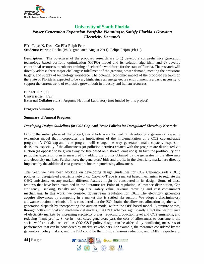
bandgap, we shift to plots used for such a determination. In Fig. 3 we plot (αhγ)2 vs. hγ for CIS data(solid line) and for two variations of the model. The customary extrapolation of the fit to the curve to the axis results in a bandgap for CIS of about 0.97 eV which is typical of reported values. However, this determination is subject to the range of absorption data used. As can be seen here and in Fig. 2, there is a change of slope at higher wavelength energies the inclusion of which would result in a different value of bandgap. Nevertheless, since the range used here is closest to the wavelength axis, we will use it to determine our operational bandgaps.
The model then uses the CIS absorption profile to represent CZTSe, and thus the CIS profile is what is expected for the absorption of single phase CZTSe. The two long-dashed curves indicate the effect on this profile due to secondary phases as discussed for Fig. 2. In this case the lower dashed curve is the profile for CZTSe containing 10% excess Zn, and the upper dashed curve is for a 20% Zn deficient film which results in the formation of CZTSe with the available Zn(80%), and CuSnSe with the remaining Cu and Sn. The effect of the film composition on the bandgap is shown in Fig. 4. Thus for Zn-deficient films there is a systematic downward shift in bandgap for increasing excess Cu/Sn which forms CuSnSe. For Zn-rich films there would be no change in bandgap, only a change in slope. Both the slope and bandgap of a film are used to
53 | P a g e
Figure 4. Bandgap dependence on the composition of CZTSe films.
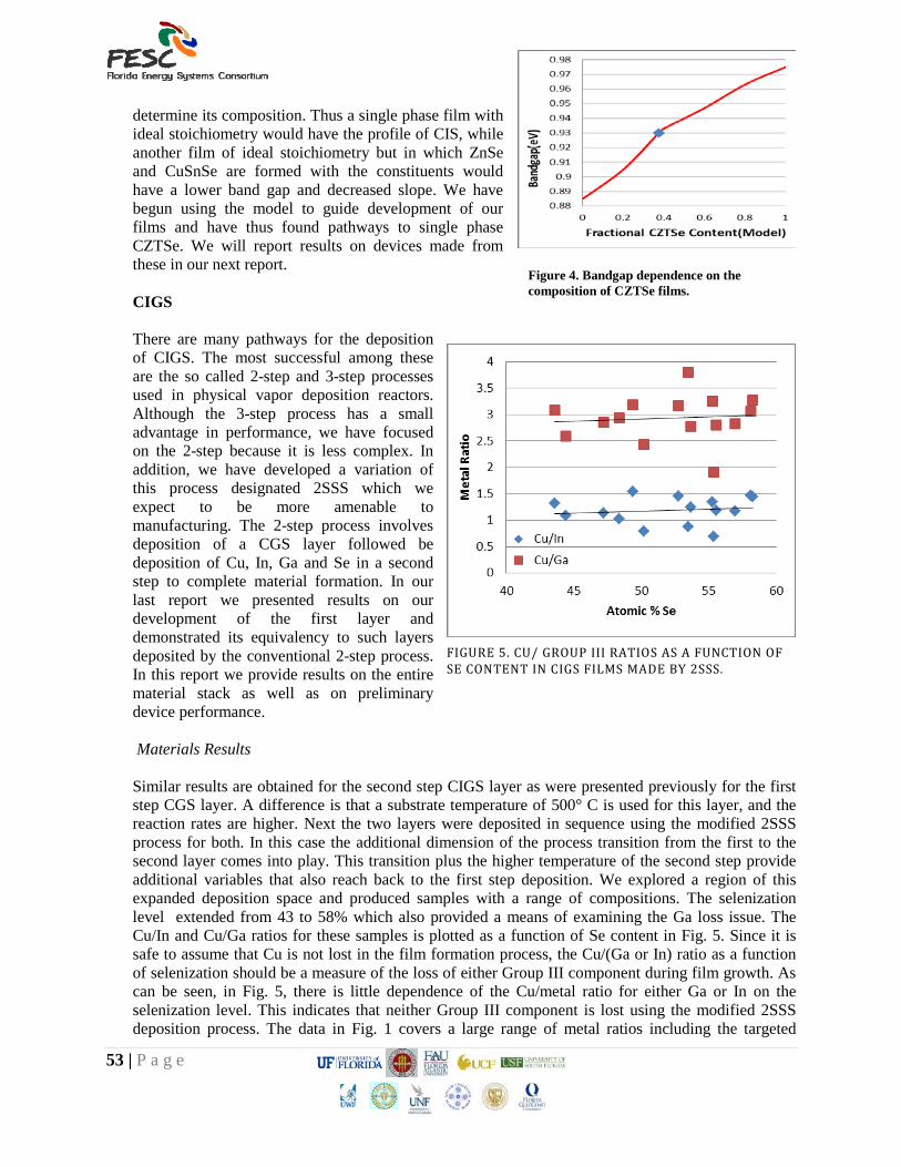
determine its composition. Thus a single phase film with ideal stoichiometry would have the profile of CIS, while another film of ideal stoichiometry but in which ZnSe and CuSnSe are formed with the constituents would have a lower band gap and decreased slope. We have begun using the model to guide development of our films and have thus found pathways to single phase CZTSe. We will report results on devices made from these in our next report. CIGS There are many pathways for the deposition of CIGS. The most successful among these are the so called 2-step and 3-step processes used in physical vapor deposition reactors. Although the 3-step process has a small advantage in performance, we have focused on the 2-step because it is less complex. In addition, we have developed a variation of this process designated 2SSS which we expect to be more amenable to manufacturing. The 2-step process involves deposition of a CGS layer followed be deposition of Cu, In, Ga and Se in a second step to complete material formation. In our last report we presented results on our development of the first layer and demonstrated its equivalency to such layers deposited by the conventional 2-step process. In this report we provide results on the entire material stack as well as on preliminary device performance. Materials Results Similar results are obtained for the second step CIGS layer as were presented previously for the first step CGS layer. A difference is that a substrate temperature of 500° C is used for this layer, and the reaction rates are higher. Next the two layers were deposited in sequence using the modified 2SSS process for both. In this case the additional dimension of the process transition from the first to the second layer comes into play. This transition plus the higher temperature of the second step provide additional variables that also reach back to the first step deposition. We explored a region of this expanded deposition space and produced samples with a range of compositions. The selenization level extended from 43 to 58% which also provided a means of examining the Ga loss issue. The Cu/In and Cu/Ga ratios for these samples is plotted as a function of Se content in Fig. 5. Since it is safe to assume that Cu is not lost in the film formation process, the Cu/(Ga or In) ratio as a function of selenization should be a measure of the loss of either Group III component during film growth. As can be seen, in Fig. 5, there is little dependence of the Cu/metal ratio for either Ga or In on the selenization level. This indicates that neither Group III component is lost using the modified 2SSS deposition process. The data in Fig. 1 covers a large range of metal ratios including the targeted
FIGURE 5. CU/ GROUP III RATIOS AS A FUNCTION OF SE CONTENT IN CIGS FILMS MADE BY 2SSS.

54 | P a g e
values of 0.9 ≤ Cu/(In+Ga) ≤ 1 and 0.2 ≤ Ga/(In+Ga) ≤ 0.3 for good device performance. In the next section we report results for devices made with 2SSS processed films. Device Results
With an established process for forming quality absorber layers we next turned to device fabrication. To proceed systematically our initial devices were made in a hybrid format. That is, the first layer consisting of Cu-rich CGS was deposited by the 2SSS process, while the second CIGS layer was deposited by co-evaporation. The format for these initial devices was an array of 0.1 cm2 devices. The small device size is useful for early stage development because there is grading in the metal ratios across the array that can provide additional insights to device performance. The devices do not have metal grids, so fill factors cannot be determined. But comparisons can be made in terms of Voc’s and Jsc’s. Our reference co-deposition devices made under the same conditions as the 2SSS devices had Voc’s in the low 500 mV range and Jsc’s in the low 30 mA/cm2 range. The initial hybrid 2SSS devices had Voc’s in the same range and slightly lower Jsc’s. Because of the nature of the 2SSS process we are particularly concerned with the transport properties of the absorber. Although our materials studies indicate that the 2SSS films have both compositional and macro-structural properties similar to co-deposition films, small differences at the point defect level can have significant influence on performance. Quantum efficiency is very sensitive to transport properties and is thus a good tool for evaluation. In Fig. 6 we show a comparison of QE for films grown with the hybrid 2SSS process and by co-deposition. As can be seen, the performance is at about 80% of that of co-deposition films with additional higher QE for the 2SSS films in the blue region of the spectrum. The increase in the ratio in the red region is attributable to a smaller bandgap for the 2SSS films. This is surprising since this would occur in the space charge region which is largely formed by co-deposition in these hybrid devices. It would seem that less Ga is supplied to the space charge region by the underlying CGS layer when it is deposited by the 2SSS process. We have experienced complex behavior of Ga in devices made using similar techniques in the past and have developed some understanding of the mechanisms with the help of device simulations. We will apply these techniques to 2SSS structures going forward to guide their future development. Having attained materials properties comparable to co-deposition we expect to achieve state-of-the art performance in devices.
FIGURE 6. RATIO OF QUANTUM EFFICIENCIES FOR CIGS DEVICES MADE BY HYBRID 2SSS PROCESSING TO CO-EVAPORATION PROCESSING.