Embed Size (px)
Citation preview

Improvement of the frit salvage process for a
cathode ray tube
Chin Young Cha\ Shri V. Iyer\ Venn Lakshmanan'% Joseph J.
Rends*" & John Trevelyan^
University of Durham, Durham, UK
Abstract
The frit salvage process is used to recycle cathode ray tubes at Phillips Display.This process involves creating a crack that will separate the interface cleanlybetween the panel and funnel components of the cathode ray tube. The currentsuccess rate of the frit salvage process is about 67%. Due to the crackpropagating into the panel, 33% of the cathode ray tubes that are lost andcannot be reused. This paper describes how a thermal stress boundary elementanalysis was carried out to select a mechanical device that improves the fritsalvage of a 27 inch cathode ray tube (CRT) by redirecting the crack to thepanel funnel interface. This application is an excellent example of using theboundary element method in an industrial setting.
1 Introduction
CRTs are commonly found in television sets and Figure 1 shows its mainfeatures. The interior of the tube contains electronics that may fail before
Transactions on Modelling and Simulation vol 20, © 1998 WIT Press, www.witpress.com, ISSN 1743-355X

638 Boundary Elements
shipping or while in service. Due to the high cost of manufacturing thetube, Phillips will try to recycle CRT by the following steps: 1. Openingup the vacuum tube at the seal edge.; 2. Removing the defectiveelectronics.; 3. Replacing the electronics.; 4. Resealing the tube so that theinterior is in a vacuum state. Step 1 is referred to as the frit salvage
process and is crucial for successfully recycling a CRT.In the frit salvage process the panel and funnel of a CRT is fritted
at the seal edge. To reuse a CRT, etching and then applying a thermalshock separates the panel and funnel at the seal edge in Figure 1. Asuccessful salvage process occurs when the crack initiates at the end of theaxes and traverses towards the corner along the seal end during thermalshock as shown in Figure 2 (line ABC). A CRT is lost when the cracktravels along the diagonal corner (line DE). The current success rate ofthe frit salvage process is about 67%, which means that 33% of thecomponents are lost and cannot be reused. Having a better understandingof the thermal shock mechanism can reduce the financial burden on
Phillips Display. To promote crack propagates along the seal edge (lineABC), i.e., increase the success rate of the frit salvage process, amechanical device is proposed to apply a pressure to all comers of theCRT as shown in Figure 2. Numerical methods are a powerful
engineering tool that can be used to obtain a better understanding of the
current frit salvage process and any modifications they are necessary toincrease the success rate.
Numerical techniques for the stress and heat transfer analyses ofengineering components have developed rapidly over the past decade, andtoday the two major alternatives are the finite element method (FEM) andthe boundary element method (BEM). Both techniques have been used tocarry out a static stress analysis of a 27-inch CRT [1, 2]. The boundaryelement results achieve a high degree of accuracy even for a single elementin the thickness direction. Although it is found to be unnecessary to use amore refined mesh, BEM also allows one to remesh the surface easily inan extremely short period of time. In contrast, the finite element resultsappear to require a minimum of two eight-node brick elements in thethickness direction before the results approach convergence. The difficultyof remeshing a FEM volume mesh is an obstacle in carrying out a rapidconvergence analysis. The simplicity of carrying out a refined boundarydiscretization allows a more detailed convergence study and thereforepromotes confidence in the stresses. In consequence, the boundary elementmodel was easier and quicker to build, more accurate and also has anextremely shorter modeling time than the finite element model. In this
Transactions on Modelling and Simulation vol 20, © 1998 WIT Press, www.witpress.com, ISSN 1743-355X
Boundary Elements 639
paper the boundary element method will be used to analyze the current andproposed changes to the frit salvage process.
2 Problem Statement
The panel and funnel of a CRT are fritted at seal edge. To reuse a CRT,
the panel and funnel are first separated by etching the frit along the sealedge by using Nitric acid at 130 °F. The glass is then cooled from 130 °Fto 60 TF with water at 60 °F in 50 seconds. During thermal shock, a crackhas been observed to initiate at the end of the axes and traverse toward thecorner along the seal end (line ABC in Figure 2). However, 33% of theCRTs are lost due to the crack traveling along the diagonal corner (lineADEC) as shown in Figure 2. In order to prevent the crack from travelingalong the diagonal corner (line DE) a mechanical device is used to apply apressure at all corners of the CRT as shown in Figure 2. The mechanicaldevice will redirect the crack along the seal edge to point B by reducing thestress at the corner (area DE) and increasing the stress along the seal edge(point B).
In order to analyze the mechanism, which caused the crack, BEM
was chosen due to its ease of use and its well-known suitability for solvingproblems involving cracks and stress concentrations [3]. A thermal stressanalysis was carried out using the commercial boundary element codeBEASY [4]. A steady state heat transfer analysis was first carried out todetermine the temperature variation throughout the CRT during thermalshock. A cooling rate of 84 T/min was assumed to simulate the actualprocess of cooling from 130 °F to 60 °F in 50 seconds.
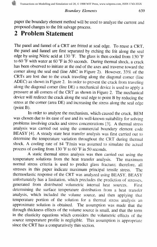
A static thermal stress analysis was then carried out using thetemperature solutions from the heat transfer analysis. The maximumnormal stress criteria is used to predict glass fracture; therefore, allstresses in this paper indicate maximum principal tensile stress. Thethermoelastic response of the CRT was analyzed using BEASY. BEASYunfortunately has a limitation, which precludes the prediction of stresses,generated from distributed volumetric internal heat sources. Firstdetermining the surface temperature distribution from a heat transferanalysis, which included the volume source, and then applying thattemperature portion of the solution for a thermal stress analysis anapproximate solution is obtained. The assumption was made that thethrough thickness effects of the volume source is small, and that the termin the elasticity equations which considers the volumetric effects of thesource temperature profile is negligible. This assumption is appropriatesince the CRT has a comparatively thin section.
Transactions on Modelling and Simulation vol 20, © 1998 WIT Press, www.witpress.com, ISSN 1743-355X
640 Boundary Elements
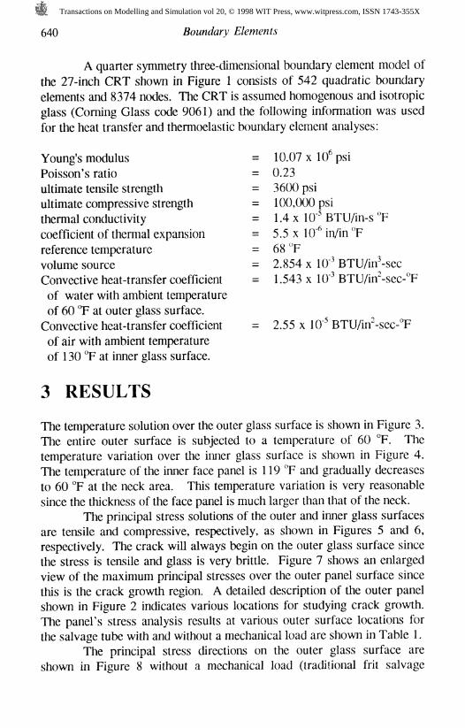
A quarter symmetry three-dimensional boundary element model ofthe 27-inch CRT shown in Figure 1 consists of 542 quadratic boundaryelements and 8374 nodes. The CRT is assumed homogenous and isotropicglass (Corning Glass code 9061) and the following information was used
for the heat transfer and thermoelastic boundary element analyses:
Young's modulus = 10.07 x 10^ psi
Poisson's ratio = 0.23ultimate tensile strength = 3600 psiultimate compressive strength = 100,000 psithermal conductivity = 1.4 x 10"* BTU/in-s °F
coefficient of thermal expansion = 5.5 x 10"̂ in/in °F
reference temperature = 68 "Fvolume source = 2.854 x 10~* BTU/in̂ -secConvective heat-transfer coefficient = 1.543 x 10~* BTU/in"-sec-°F
of water with ambient temperatureof 60 °F at outer glass surface.
Convective heat-transfer coefficient = 2.55 x 10"* BTU/uT-sec-°F
of air with ambient temperatureof 130 TF at inner glass surface.
3 RESULTS
The temperature solution over the outer glass surface is shown in Figure 3.The entire outer surface is subjected to a temperature of 60 °F. Thetemperature variation over the inner glass surface is shown in Figure 4.The temperature of the inner face panel is 119 °F and gradually decreasesto 60 °F at the neck area. This temperature variation is very reasonablesince the thickness of the face panel is much larger than that of the neck.
The principal stress solutions of the outer and inner glass surfacesare tensile and compressive, respectively, as shown in Figures 5 and 6,respectively. The crack will always begin on the outer glass surface sincethe stress is tensile and glass is very brittle. Figure 7 shows an enlargedview of the maximum principal stresses over the outer panel surface sincethis is the crack growth region. A detailed description of the outer panelshown in Figure 2 indicates various locations for studying crack growth.The panel's stress analysis results at various outer surface locations forthe salvage tube with and without a mechanical load are shown in Table 1.
The principal stress directions on the outer glass surface areshown in Figure 8 without a mechanical load (traditional frit salvage
Transactions on Modelling and Simulation vol 20, © 1998 WIT Press, www.witpress.com, ISSN 1743-355X

Boundary Elements 641
process). The crack starts at point A (on major axis), which has themaximum stress value (3323 psi), and proceeds along the seal edge duringthermal shock. The crack then changes direction towards point D insteadof point B (seal edge) since the stress of point D is 524 psi greater thanpoint B. This is consistent with Figure 8 since the crack propagatesperpendicular to the principal stress direction at point D. The crack thencontinues to propagate towards point E and then proceeds to the seal edgeand then along the seal edge to point C. The direction and location of thecrack obtained by the boundary element analysis without the mechanical
load is consistent with those observed in the frit salvage procedure atPhillips Display. The analysis determined that maximum stresses arelocated near the blend radius on the panel skirt at approximately 1-2inches on either side of the diagonal corner. Also, it was found that thestresses along the frit seal edge are uniform from the end of the major andminor axes towards the diagonal.
Table 1. Principal Stress Comparison of the Outer Panel Between theSalvage Tube with and without a Mechanical Load.
PotatsStress of Salvage Tube (psi)Stress of Salvage Tube withMechanical Load (psi)Change in Stress (psi)
A3323
2867
-456
B1275
1610
+335
C2889
2562
-327
D1799
1202
-597
E1768
1134
-634
A 3 ¥4 inch diameter Yates hydraulic cylinder is used to apply amechanical pressure load of 1533 psi on the diagonal skirt to preventthermal failure along the diagonal corner, i.e., to promote a crack alongline ABC instead of line ADEC in Figure 2. The hatched area in Figure 2designates the location of the mechanical pressure load. The principalstresses on the outer glass surface with the mechanical load are tensilewith the exception of a compression area on the diagonal corner where themechanical load is applied as shown in Figure 9. The principal stresses onthe inner glass surface with the mechanical load are compressive as shownin Figure 10. The panel's stress analysis results at various outer surfacelocations for the salvage tube with and without a mechanical load areshown in Table 1. The + and - signs in Table 1 indicate the amount ofincreased and decreased principal stress, respectively, on salvage tube withthe mechanical load.
Figure 11 shows the principal stress variation over the outer panelwhen it is subjected to a mechanical load. These results indicate that the
Transactions on Modelling and Simulation vol 20, © 1998 WIT Press, www.witpress.com, ISSN 1743-355X
642 Boundary Elements
stresses of points D and E have been reduced to 597 psi and 634 psi,respectively, as shown in Table 1. The amount of the stress reduction bythe pressure load is significant. The principal stress directions at points Dand E are perpendicular to the seal edge as shown in Figure 12. Withoutthe mechanical load, the directions of the principal stresses at points D andE were approximately 135° and 45°, respectively, where the inclination is
with respect to the seal edge as shown in Figure 8. The direction andreduction of these principal stresses insure that the crack does notpropagate through points D and E. Furthermore, the principal stress ofpoint B has increased 335 psi due to the pressure load. This stressincrease promotes crack propagation through point B. The crack will start
at point A, which has the maximum stress, proceed along the seal edge topoint B, which has 408 psi higher stress than D, and continues to follow
the seal edge to point C.
4 Conclusion
The direction and location of the crack obtained by the boundary element
analysis was consistent with those observed in the frit salvage procedure atPhillips Display. A 3 V4 inch diameter Yates hydraulic cylinder is used toapply a mechanical load on the diagonal skirt to prevent thermal failurealong the diagonal corner. A boundary element analysis was carried outwith the mechanical load applied as a pressure on the diagonal skirt. As aresult, the maximum principal stresses on the diagonal corner havedecreased significantly while the stresses along the seal at the diagonalincreased. Consequently, the crack continues to transverse along the highstress lines at the seal edge as required for a successful frit salvageprocess.
References
[1] Cha, C. Y., Iyer, S. and Trevelyan J., "Stress Failure Analysis ofNeck Breakage of Cathode Ray Tube," Proceedings of 17*International Conference on Boundary Element Methods inEngineering, Vol. 1, Computational Mechanics Publications,Southampton, UK, pp. 403-419, 1995.
[2] Cha, C. Y., Iyer, S. and Trevelyan J., "Comparison of Convergenceand Modeling Times for Cathode Ray Tube Stress Analysis with theFinite Element and Boundary Element Methods/' Boundary Element
Transactions on Modelling and Simulation vol 20, © 1998 WIT Press, www.witpress.com, ISSN 1743-355X
Boundary Elements 643
Communications, Computational Mechanics Publications,Southampton, UK, Vol. 6, No. 1, pp. 1-5, January, 1995.
[3] Aliabadi, M. H. and Rooke, D. P., Numerical Fracture Mechanics,
Computational Mechanics Publications, Southampton, UK, andKluwer Academics Publisher, Dordrecht, 1991.
[4] BEASY, Computational Mechanics, Southampton, UK, and Billerica,MA.
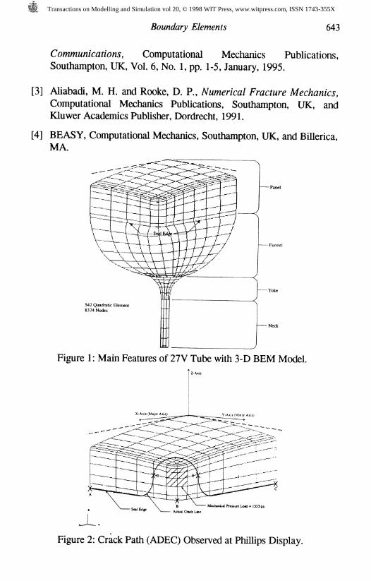
542 Quadratic Element8374 Nodes
Figure 1: Main Features of 27V Tube with 3-D BEM Model.
Mechanical Preuure Load - 1533 psi
Figure 2: Crack Path (ADEC) Observed at Phillips Display.
Transactions on Modelling and Simulation vol 20, © 1998 WIT Press, www.witpress.com, ISSN 1743-355X

644 Boundary Elements
Figure 3: Temperature Solution over the Outer Glass Surface.
Figure 4: Temperature Solution over the Inner Glass Surface.
Transactions on Modelling and Simulation vol 20, © 1998 WIT Press, www.witpress.com, ISSN 1743-355X

Boundary Elements 645
Figure 5: Principal Stress Solution on Outer Glass Surface.
Figure 6: Principal Stress Solution over Outer Surface.
Transactions on Modelling and Simulation vol 20, © 1998 WIT Press, www.witpress.com, ISSN 1743-355X

646 Boundary Elements
Figure 7: Maximum Principal Stress on Outer Panel Surface in
Crack Region.
Load set 3 Symbolic result display-HE. THERMAL STRESS ANALYSIS OF 27V SALVAGE TUBEFILE NAME : BE27VS.BM
" f f *-*
< l^-TTtpr^^vr, %=1 -t'
Figure 8: Principal Stress Directions on Outer Glass Surface.
Transactions on Modelling and Simulation vol 20, © 1998 WIT Press, www.witpress.com, ISSN 1743-355X

Boundary Elements 647
Figure 9: Principal Stresses on Outer Glass Surface with Mechanical
Load.
Figure 10: Principal Stresses on Inner Glass Surface with
Mechanical Load.
Transactions on Modelling and Simulation vol 20, © 1998 WIT Press, www.witpress.com, ISSN 1743-355X

648 Boundary Elements
Figure 11: Principal Stress on Outer Panel Surface with Mechanical
Load in Crack Region.
Load set 3 Symbolic result displayTHE THERMAL STRESS ANALYSIS OF 27V SALVAGE TUBE WITH THE STRESS PROTECTORFILE NAME : BE27VP.DA1
<"\
f r rrr9%
[ ^ i : I : | 'iriH^ : < ' IL , ^ ^ * * * - : ^ - t " ^ i , I
k t ^ l t l ' t ^ ! i t -r ̂ ^$ I !i f i i r ^ v V 3 t ^ ^ { - t ^ F l * » f ^f * * 4 t % t H » ! » * * * *
f •). v
Figure 12: Principal Stress Directions on Outer Panel Surface with
Mechanical Load.
Transactions on Modelling and Simulation vol 20, © 1998 WIT Press, www.witpress.com, ISSN 1743-355X