Embed Size (px)
Citation preview

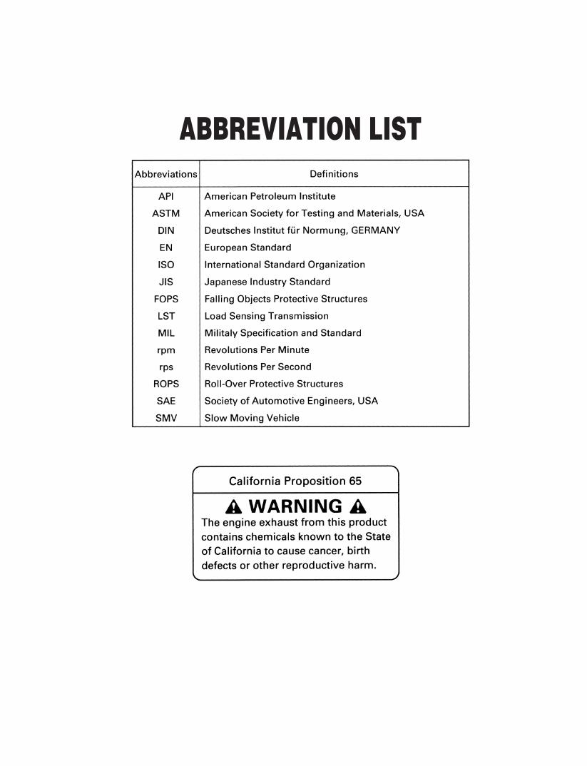

UNIVERSAL SYMBOLS
3 Safety Alert Symbol
l Engine Oil-Pressure
g Battery Charging Condition
n Diesel Preheat/Glow Plugs
LST Temperature
Q LST Oil-Pressure
k Limited Travel Speed
p Parking Brake
0 Hazard Warning Lights
9 Headlight
R Diesel Fuel
E Hydraulic Oil
Bucket Up
Bucket Down
Bucket Tilt
Bucket Dump
Bucket Float
J Travel Forward
K Travel Backward
Lock
Unlock
As a guide to the operation of your machine, various universal symbols have been utilized on the instruments andcontrols. The symbols are shown below with an indication of their meaning.
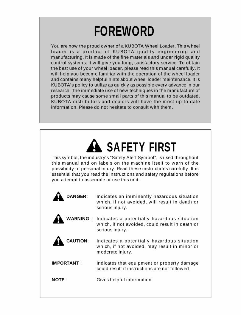
FOREWORD
3 SAFETY FIRSTThis symbol, the industry's "Safety Alert Symbol", is used throughoutthis manual and on labels on the machine itself to warn of thepossibility of personal injury. Read these instructions carefully. It isessential that you read the instructions and safety regulations beforeyou attempt to assemble or use this unit.
3 DANGER : Indicates an imminently hazardous situationwhich, if not avoided, will result in death orserious injury.
3 WARNING : Indicates a potentially hazardous situationwhich, if not avoided, could result in death orserious injury.
3 CAUTION: Indicates a potentially hazardous situationwhich, if not avoided, may result in minor ormoderate injury.
IMPORTANT : Indicates that equipment or property damagecould result if instructions are not followed.
NOTE : Gives helpful information.
You are now the proud owner of a KUBOTA Wheel Loader. This wheelloader is a product of KUBOTA quality engineering andmanufacturing. It is made of the fine materials and under rigid qualitycontrol systems. It will give you long, satisfactory service. To obtainthe best use of your wheel loader, please read this manual carefully. Itwill help you become familiar with the operation of the wheel loaderand contains many helpful hints about wheel loader maintenance. It isKUBOTA's policy to utilize as quickly as possible every advance in ourresearch. The immediate use of new techniques in the manufacture ofproducts may cause some small parts of this manual to be outdated.KUBOTA distributors and dealers will have the most up-to-dateinformation. Please do not hesitate to consult with them.
CONTENTS
SAFE OPERATION ............................................................................................. 1SERVICING OF WHEEL LOADER ............................................................................. 1
SPECIFICATIONS....................................................................................................... 2SPECIFICATION TABLE ......................................................................................... 2
INSTRUMENT PANEL AND CONTROLS................................................................... 5
OPERATING THE ENGINE......................................................................................... 9DAILY CHECK ......................................................................................................... 9STARTING THE ENGINE........................................................................................ 9COLD WEATHER STARTING............................................................................... 10CHECKS IMMEDIATELY AFTER ENGINE START .............................................. 11STOPPING THE ENGINE...................................................................................... 11JUMP STARTING .................................................................................................. 12
OPERATING THE MACHINE.................................................................................... 13HOW TO USE A NEW MACHINE.......................................................................... 13STARTING............................................................................................................. 13SAFETY LEVERS AND APPLIANCE .................................................................... 14
Safety Key Start System.................................................................................................14Bucket Lever Lock ..........................................................................................................14Service Port Lever Lock..................................................................................................15Lift Arm Support..............................................................................................................15Roll-Over Protective Structures (ROPS) / Falling Objective Protective Structures (FOPS)........................................................................................................................................16Steering Frame Lock ......................................................................................................17Parking Brake Switch......................................................................................................18Hourmeter / Tachometer.................................................................................................18Fuel Gauge.....................................................................................................................19Coolant Temperature......................................................................................................19Easy Checker .................................................................................................................19Turn Signal Switch..........................................................................................................20Headlight Switch .............................................................................................................20Hazard Lamp Switch.......................................................................................................20Fuse Box.........................................................................................................................20
CONTROL LEVERS AND PEDALS....................................................................... 21Accelerator Pedal ...........................................................................................................21Inching and Brake Pedals...............................................................................................21Travel Speed Limiter Switch ...........................................................................................21Shuttle Change Lever .....................................................................................................22Bucket Lever...................................................................................................................22
CAB TYPE MACHINES ......................................................................................... 23Opening/Closing of CAB Door(CAB type only)...............................................................23Interior Lamp(CAB type only) .........................................................................................23Wiper/Washer Switch(CAB type only) ............................................................................23Heater Switch(CAB type only) ........................................................................................24
TRAVELING........................................................................................................... 24
CONTENTS
Starting ...........................................................................................................................24Turning............................................................................................................................25Deceleration on a Slope .................................................................................................25Traveling on rough roads................................................................................................25Traveling on Snow..........................................................................................................25
STOPPING............................................................................................................. 26HOW TO USE THE INCHING PEDAL................................................................... 26
Inching Pedal Operation .................................................................................................26Use the Inching Pedal According to the Job...................................................................27
TYPICAL JOBS USING A WHEEL LOADER ........................................................ 29Digging and Loading.......................................................................................................29Refilling...........................................................................................................................30Leveling Ground .............................................................................................................30Loading onto a Truck......................................................................................................31
MULTI-COUPLER ..................................................................................................... 32ATTACHING AND DETACHING THE FRONT ATTACHMENTS .......................... 32
Attaching the Front Attachments ....................................................................................32Attaching the Front Attachment ......................................................................................33Hoses fitting for Hydraulic Multi-Coupler ........................................................................34
TRANSPORT BY TRUCK ......................................................................................... 35
HANDLING LOADER IN COLD-WEATHER.............................................................. 37PREPARATIONS FOR COLD WEATHER ............................................................ 37AFTER-OPERATION DIRECTIONS...................................................................... 37
MAINTENANCE......................................................................................................... 38SERVICE INTERVALS .......................................................................................... 39
Service Interval Chart (Do all previous checks in addition to New checks.) ...................39LUBRICANTS ........................................................................................................ 41
Select the Grade by Referring to the Table. ...................................................................41
PERIODIC SERVICE................................................................................................. 42HOW TO OPEN THE ENGINE COVER ................................................................ 42
Engine Cover ..................................................................................................................42DAILY CHECK ....................................................................................................... 42
Checking Coolant Level and Replenishing.....................................................................42Checking the Engine Oil .................................................................................................43Checking Hydraulic Oil (LST Oil) Level ..........................................................................44Checking the Fuel and Replenishing..............................................................................44Checking and Replenishment of Oil in the Brake Fluid Reservoir ..................................45Grease Fittings ...............................................................................................................45Checking Tire Pressure, Wear and Damage and Bolts ..................................................46Checking and Cleaning the Radiator and Oil Cooler Fins ..............................................46Checking the Parking Brake ...........................................................................................47Checking the Brake Pedal ..............................................................................................47Checking the Steering Wheel .........................................................................................47Checking and Tighten Loose Bolts and Nuts..................................................................47Checking Electrical Wiring for Short-circuits and Loose Terminals ................................47Checking the SMV Emblem for Stains and Damage......................................................47Checking the Lamps and Meters ....................................................................................47Testing the Horn .............................................................................................................47Checking Oil and Water Leak.........................................................................................47
CONTENTS
Cleaning and Checking after Operating in Muddy Areas................................................48EVERY 50 HOURS SERVICE ............................................................................... 48
Draining of the Fuel Tank ...............................................................................................48Battery ............................................................................................................................49
EVERY 200 HOURS SERVICE ............................................................................. 51Checking and Adjusting Fan Belt Tension......................................................................51Checking Radiator Hoses (water pipes) .........................................................................52Cleaning and Checking Air Cleaner Element .................................................................52Air Filter Maintenance.....................................................................................................53Checking Fuel Line and Intake Air Line ..........................................................................53
EVERY 250 HOURS SERVICE ............................................................................. 53Changing Engine Oil (change it after first 50 hours of operation.)..................................53
EVERY 500 HOURS SERVICE ............................................................................. 54Replacing Engine Oil Filter Cartridge (change it after first 50 hours of operation.) ........54Checking and Replenishing Oil in the Front / Rear Axle Differential Cases ...................55Replacing LST Oil Filter Cartridge..................................................................................55Replacing Return Filter ...................................................................................................56Changing the Fuel Filter .................................................................................................56
EVERY 1000 HOURS SERVICE ........................................................................... 57Changing Oil for the Front and Rear Axle Differential Cases (Change oil the first time after 1st 500 hrs. use.) ............................................................................................................57Changing Oil in Hydraulic Oil Tank and the Suction Filter (after 1st 500 hrs. use).........57Replacing Air Cleaner Element.......................................................................................58
EVERY 1500 HOURS SERVICE ........................................................................... 58Checking Fuel Injection Nozzle (Injection Pressure) ......................................................58
EVERY 2000 HOURS SERVICE ........................................................................... 58Checking Alternator Starter Motor ..................................................................................58
EVERY 3000 HOURS SERVICE ........................................................................... 59Checking Injection Pump................................................................................................59
EVERY TWO YEARS SERVICE............................................................................ 59Checking and Replacing Fuel Pipe and Rubber Hoses..................................................59Replacing Radiator Hoses (water pipes) ........................................................................59Replacing Fuel hoses .....................................................................................................59Replacing Intake Air Line................................................................................................59Changing Coolant ...........................................................................................................60Periodic Parts Replacement ...........................................................................................60
SERVICE AS REQUIRED...................................................................................... 61Checking the Electrical System, Handling Fuses ...........................................................61Bleeding the Fuel System...............................................................................................62Bleeding Air from the Brake Fluid System......................................................................62
TIRES..................................................................................................................... 63Handling Tires.................................................................................................................63Conservation of Tires......................................................................................................64Changing Tires ...............................................................................................................64Mounting the Tires ..........................................................................................................64
STORAGE ................................................................................................................. 65CAUTION WHEN WASHING THE MACHINE ....................................................... 65
TROUBLESHOOTING............................................................................................... 66ENGINE TROUBLES AND REPAIRS.................................................................... 66TROUBLES IN TRAVELING SYSTEM.................................................................. 67

CONTENTS
HYDRAULIC SYSTEM TROUBLES AND REPAIRS............................................. 68
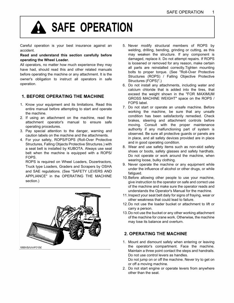
1SAFE OPERATION
SAFE OPERATION
Careful operation is your best insurance against anaccident.Read and understand this section carefully beforeoperating the Wheel Loader.All operators, no matter how much experience they mayhave had, should read this and other related manualsbefore operating the machine or any attachment. It is theowner's obligation to instruct all operators in safeoperation.1. Know your equipment and its limitations. Read thisentire manual before attempting to start and operatethe machine.
2. If using an attachment on the machine, read theattachment operator's manual to ensure safeoperating procedures.
3. Pay special attention to the danger, warning andcaution labels on the machine and the attachments.
4. For your safety, ROPS/FOPS (Roll-Over ProtectiveStructures, Falling Objects Protective Structures.) witha seat belt is installed by KUBOTA. Always use seatbelt when the machine is equipped with a ROPS/FOPS.ROPS is required on Wheel Loaders, Dozertractors,Truck type Loaders, Graders and Scrapers by OSHAand SAE regulations. (See "SAFETY LEVERS ANDAPPLIANCE" in the OPERATING THE MACHINEsection.)
5. Never modify structural members of ROPS bywelding, drilling, bending, grinding or cutting, as thismay weaken the structure. If any component isdamaged, replace it. Do not attempt repairs. If ROPSis loosened or removed for any reason, make certainall parts are reinstalled correctly.Tighten mountingbolts to proper torque. (See "Roll-Over ProtectiveStructures (ROPS) / Falling Objective ProtectiveStructures (FOPS)".)
6. Do not install any attachments, including water andcalcium chloride that is added into the tires, thatexceed the weight shown in the "FOR MAXIMUMGROSS MACHINE WEIGHT" space on the ROPS /FOPS label.
7. Do not start or operate an unsafe machine. Beforeworking the machine, be sure that any unsafecondition has been satisfactorily remedied. Checkbrakes, steering and attachment controls beforemoving. Consult with the proper maintenanceauthority if any malfunctioning part of system isobserved. Be sure all protective guards or panels arein place, and all safety devices provided are in placeand in good operating condition.
8. Wear and use safety items such as non-skid safetyshoes or boots, safety glasses and safety hardhats.Do not operate or work around the machine, whenwearing loose, bulky clothing.
9. Never operate the machine or any equipment whileunder the influence of alcohol or other drugs, or whilefatigued.
10.Before allowing other people to use your machine,give instruction to the operator on safe and correct useof the machine and make sure the operator reads andunderstands the Operator's Manual for the machine.
11. Inspect your seat belt daily for signs of fraying, wear orother weakness that could lead to failure.
12.Do not use the loader bucket or attachment to lift orcarry a person.
13.Do not use the bucket or any other working attachmentof the machine for crane work. Otherwise, the machinemay lose its balance and overturn.
1. Mount and dismount safely when entering or leavingthe operator's compartment. Face the machine.Maintain a three point contact the steps and handrails.Do not use control levers as handles. Do not jump on or off the machine. Never try to get onor off a moving machine.
2. Do not start engine or operate levers from anywhereother than the seat.
1. BEFORE OPERATING THE MACHINE
2. OPERATING THE MACHINE
SAFE OPERATION2
3. Before starting the engine, fasten the seat belt, makesure that the shuttle change lever is set at the neutralposition, the parking brake switch is set at the parkingposition and the bucket is lowered to the ground.
4. Do not start engine by shorting across starterterminals.
5. Watch where you are going at all times. Watch for andavoid obstacles.
6. Never permit passengers on the machine. Keepbystanders away from the machine during operation.
7. When working around other machines, let the otherdrivers know what you are doing at all times.
8. Never allow anyone to get under or near the bucket orattachment when it is raised.
9. When raising the bucket or attachment, take extracaution to prevent it from touching overhead wires orother obstacles. Contact with wires may cause deathby electrical shock.
10.Keep away from the muffler while the engine is runningand immediately after it has stopped.
11.Unreasonable operation such as on dangerousterrain, beyond the load capacity or beyond theintended use of the machine must be avoided as itmay cause the machine to tip over.
12.Do not drive the machine close edges of ditches orbanks which may collapse under the weight of themachine, especially when the ground is loose or wet.
13.Slow down for turns, uneven terrain and slopes toavoid tip over.
14.When transporting a load, keep the loader bucket aslow as possible to avoid tip over. Be extremely carefulwhen working on inclines.
15.Operation on slopes can be dangerous. Rain, snow,gravel soft ground, etc. will change the groundconditions. Do not operate the machine inquestionable ground conditions. If operating on aslope or ramp, always slow down, travel straight upand down the incline and not across. Keep the bucketas low as possible. If you do not follow theseinstructions, the machine can go out of control and tipover.
16. Avoid turning on a slope.17. Never perform digging or shoveling with the machine
in the articulated condition, or the machine may tipover.
18.Never dig or shovel at high speed. Such operation cancause the machine to lose stability and its rear wheelsto lift off the ground, which may lead to seriouspersonal injury or death.
19.Do not go up or down a 30 or steeper hill. Otherwise,the machine may skid sideways or turn on its side. Ifthe ground is ungraded or soft, limit the slope below15 .
20.To avoid possible machine tip over, do not operate themachine in any site whose terrain cannot beascertained, such as ground covered with seeds orsnow and check for hidden projections, dents, roadshoulders, etc. beforehand, and take care not toapproach them during work.
21.Be sure to ease off the accelerator at the end ofbackfilling grooves, or areas at the edge of cliffs orpond banks, or at the end of an ascent. Upon removalof the external load, the machine speed willautomatically increase, reduce speed to avoidentering grooves or tipping over.
22.To avoid machine slip or tipping over, do not operatethe machine on ungraded or soft terrain, such as landfills. Grade and compact the site beforehand at alltimes.
23.Avoid running the engine for a long time indoors.When the engine must be run indoors, be sure to openthe windows and doors. Carbon monoxide gas fromexhaust is colorless, odorless and deadly.
24.Check that no one is near the muffler exhaust beforestarting the engine. If exposed to exhaust fume, he orshe may get burned or poisoned. Check that there isno flammable objects, such as dead leaves, sheets ofpaper, or pieces of cloth, attached to areas around theengine before starting the engine.
25.To avoid the danger of exhaust fume poisoning, do notoperate the engine, in a closed building without properventilation. Carbon monoxide is odorless, colorless,and deadly.
26.Use extra caution when backing up, look behind anddown-make sure area is clear before moving.
27.When parking your machine if at all possible park on afirm, flat and level surface; if not, park across a slope.Set the parking brake(s), lower the implements to theground, remove the key from the ignition and lock thecab door (if equipped) and chock the crawlers or thewheels.
C Safety for childrenTragedy can occur if the operator is not alert to thepresence of children. Children generally are attached tomachines and the work they do.
28.Never assume that children will remain where you lastsaw them.
29.Keep children out of the work area and under thewatchful eye of another responsible adult.
30.Be alert and shut your machine down if children enterthe work area.
31.Never carry children on your machine. There is no safeplace for them to ride. They may fall off and be runover or interfere with your control of the machine.
32.Never allow children to operate the machine evenunder adult supervision.
33.Never allow children to play on the machine or on theimplement.
3SAFE OPERATION
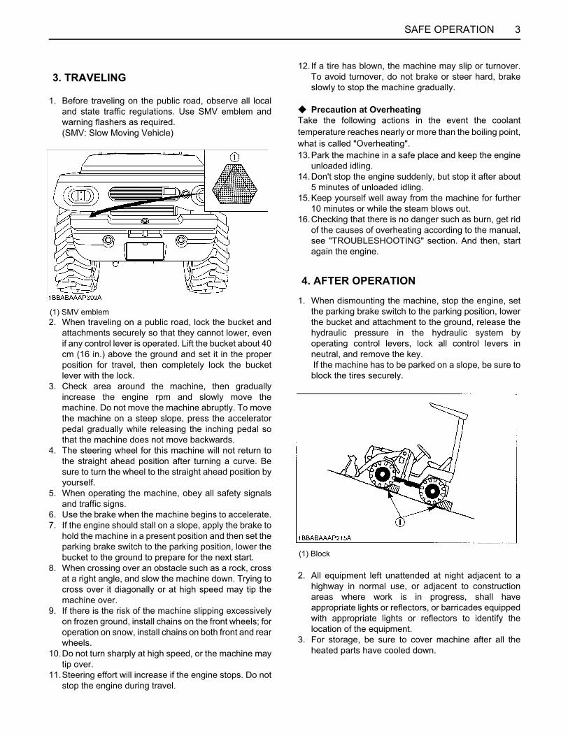
1. Before traveling on the public road, observe all localand state traffic regulations. Use SMV emblem andwarning flashers as required.(SMV: Slow Moving Vehicle)
2. When traveling on a public road, lock the bucket andattachments securely so that they cannot lower, evenif any control lever is operated. Lift the bucket about 40cm (16 in.) above the ground and set it in the properposition for travel, then completely lock the bucketlever with the lock.
3. Check area around the machine, then graduallyincrease the engine rpm and slowly move themachine. Do not move the machine abruptly. To movethe machine on a steep slope, press the acceleratorpedal gradually while releasing the inching pedal sothat the machine does not move backwards.
4. The steering wheel for this machine will not return tothe straight ahead position after turning a curve. Besure to turn the wheel to the straight ahead position byyourself.
5. When operating the machine, obey all safety signalsand traffic signs.
6. Use the brake when the machine begins to accelerate.7. If the engine should stall on a slope, apply the brake to
hold the machine in a present position and then set theparking brake switch to the parking position, lower thebucket to the ground to prepare for the next start.
8. When crossing over an obstacle such as a rock, crossat a right angle, and slow the machine down. Trying tocross over it diagonally or at high speed may tip themachine over.
9. If there is the risk of the machine slipping excessivelyon frozen ground, install chains on the front wheels; foroperation on snow, install chains on both front and rearwheels.
10.Do not turn sharply at high speed, or the machine maytip over.
11.Steering effort will increase if the engine stops. Do notstop the engine during travel.
12. If a tire has blown, the machine may slip or turnover.To avoid turnover, do not brake or steer hard, brakeslowly to stop the machine gradually.
C Precaution at OverheatingTake the following actions in the event the coolanttemperature reaches nearly or more than the boiling point,what is called "Overheating".13.Park the machine in a safe place and keep the engine
unloaded idling.14.Don't stop the engine suddenly, but stop it after about
5 minutes of unloaded idling.15.Keep yourself well away from the machine for further
10 minutes or while the steam blows out.16.Checking that there is no danger such as burn, get rid
of the causes of overheating according to the manual,see "TROUBLESHOOTING" section. And then, startagain the engine.
1. When dismounting the machine, stop the engine, setthe parking brake switch to the parking position, lowerthe bucket and attachment to the ground, release thehydraulic pressure in the hydraulic system byoperating control levers, lock all control levers inneutral, and remove the key. If the machine has to be parked on a slope, be sure toblock the tires securely.
2. All equipment left unattended at night adjacent to ahighway in normal use, or adjacent to constructionareas where work is in progress, shall haveappropriate lights or reflectors, or barricades equippedwith appropriate lights or reflectors to identify thelocation of the equipment.
3. For storage, be sure to cover machine after all theheated parts have cooled down.
3. TRAVELING
(1) SMV emblem
4. AFTER OPERATION
(1) Block
SAFE OPERATION4
4. Before storing the machine for long periods of time, dothe following.A Stop the engine.A Set the parking brake switch to the parking
position.A Lower the bucket and attachment to the ground.A Release the hydraulic pressure in the hydraulic
system by operating control levers.A Lock all control levers in neutral.A Remove the key.
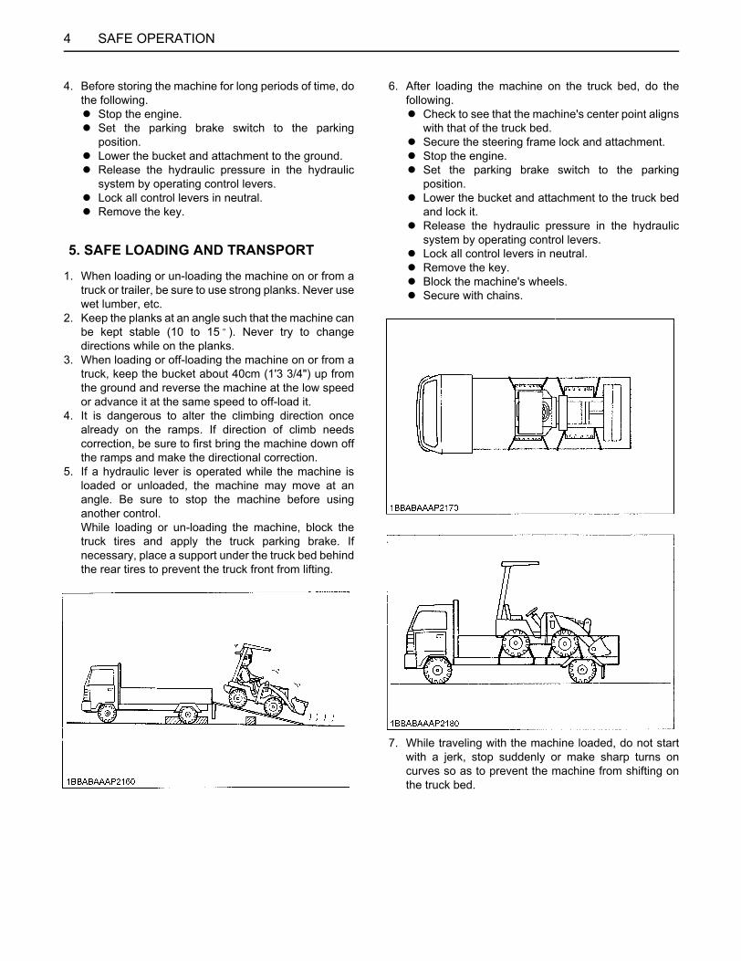
1. When loading or un-loading the machine on or from atruck or trailer, be sure to use strong planks. Never usewet lumber, etc.
2. Keep the planks at an angle such that the machine canbe kept stable (10 to 15 ). Never try to changedirections while on the planks.
3. When loading or off-loading the machine on or from atruck, keep the bucket about 40cm (1'3 3/4") up fromthe ground and reverse the machine at the low speedor advance it at the same speed to off-load it.
4. It is dangerous to alter the climbing direction oncealready on the ramps. If direction of climb needscorrection, be sure to first bring the machine down offthe ramps and make the directional correction.
5. If a hydraulic lever is operated while the machine isloaded or unloaded, the machine may move at anangle. Be sure to stop the machine before usinganother control. While loading or un-loading the machine, block thetruck tires and apply the truck parking brake. Ifnecessary, place a support under the truck bed behindthe rear tires to prevent the truck front from lifting.
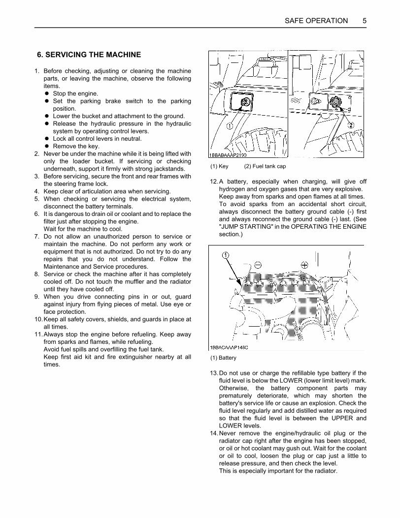
6. After loading the machine on the truck bed, do thefollowing.A Check to see that the machine's center point aligns
with that of the truck bed.A Secure the steering frame lock and attachment.A Stop the engine.A Set the parking brake switch to the parking
position.A Lower the bucket and attachment to the truck bed
and lock it.A Release the hydraulic pressure in the hydraulic
system by operating control levers.A Lock all control levers in neutral.A Remove the key.A Block the machine's wheels.A Secure with chains.
7. While traveling with the machine loaded, do not startwith a jerk, stop suddenly or make sharp turns oncurves so as to prevent the machine from shifting onthe truck bed.
5. SAFE LOADING AND TRANSPORT
5SAFE OPERATION
1. Before checking, adjusting or cleaning the machineparts, or leaving the machine, observe the followingitems.A Stop the engine.A Set the parking brake switch to the parking
position.A Lower the bucket and attachment to the ground.A Release the hydraulic pressure in the hydraulic
system by operating control levers.A Lock all control levers in neutral.A Remove the key.
2. Never be under the machine while it is being lifted withonly the loader bucket. If servicing or checkingunderneath, support it firmly with strong jackstands.
3. Before servicing, secure the front and rear frames withthe steering frame lock.
4. Keep clear of articulation area when servicing.5. When checking or servicing the electrical system,
disconnect the battery terminals.6. It is dangerous to drain oil or coolant and to replace the
filter just after stopping the engine. Wait for the machine to cool.
7. Do not allow an unauthorized person to service ormaintain the machine. Do not perform any work orequipment that is not authorized. Do not try to do anyrepairs that you do not understand. Follow theMaintenance and Service procedures.
8. Service or check the machine after it has completelycooled off. Do not touch the muffler and the radiatoruntil they have cooled off.
9. When you drive connecting pins in or out, guardagainst injury from flying pieces of metal. Use eye orface protection.
10.Keep all safety covers, shields, and guards in place atall times.
11.Always stop the engine before refueling. Keep awayfrom sparks and flames, while refueling. Avoid fuel spills and overfilling the fuel tank. Keep first aid kit and fire extinguisher nearby at alltimes.
12.A battery, especially when charging, will give offhydrogen and oxygen gases that are very explosive. Keep away from sparks and open flames at all times. To avoid sparks from an accidental short circuit,always disconnect the battery ground cable (-) firstand always reconnect the ground cable (-) last. (See"JUMP STARTING" in the OPERATING THE ENGINEsection.)
13.Do not use or charge the refillable type battery if thefluid level is below the LOWER (lower limit level) mark.Otherwise, the battery component parts mayprematurely deteriorate, which may shorten thebattery's service life or cause an explosion. Check thefluid level regularly and add distilled water as requiredso that the fluid level is between the UPPER andLOWER levels.
14.Never remove the engine/hydraulic oil plug or theradiator cap right after the engine has been stopped,or oil or hot coolant may gush out. Wait for the coolantor oil to cool, loosen the plug or cap just a little torelease pressure, and then check the level. This is especially important for the radiator.
6. SERVICING THE MACHINE
(1) Key (2) Fuel tank cap
(1) Battery
SAFE OPERATION6
15.Leaking hydraulic fluid has enough pressure topenetrate the skin and cause serious injuries.Leakages from pin holes can be totally invisible. Donot use the bare hand for checking on possibleleakages. Always use a piece of wood or cardboard. Itis strongly recommended to use a face mask or eyeprotection. Should injuries occur with leaking hydraulic fluid,contact a doctor immediately. This fluid can causegangrene or serious allergic reactions.
16. If the machine breaks down and requires towing,please contact your nearest KUBOTA dealer.In caseof an emergency, carry out the following procedure.A Remove the caps of the two high pressure relief
valves that are located at the top and bottom of thepump. Loosen the M8 nuts and tighten the adjustbolts by 6 turns. (Be careful never to loosen the M8 nuts too much.)
A Remove the two M12 bolts of the parking brakecase, and remove the two flat washers from each(total of four).
A Re-tighten the two M12 bolts.
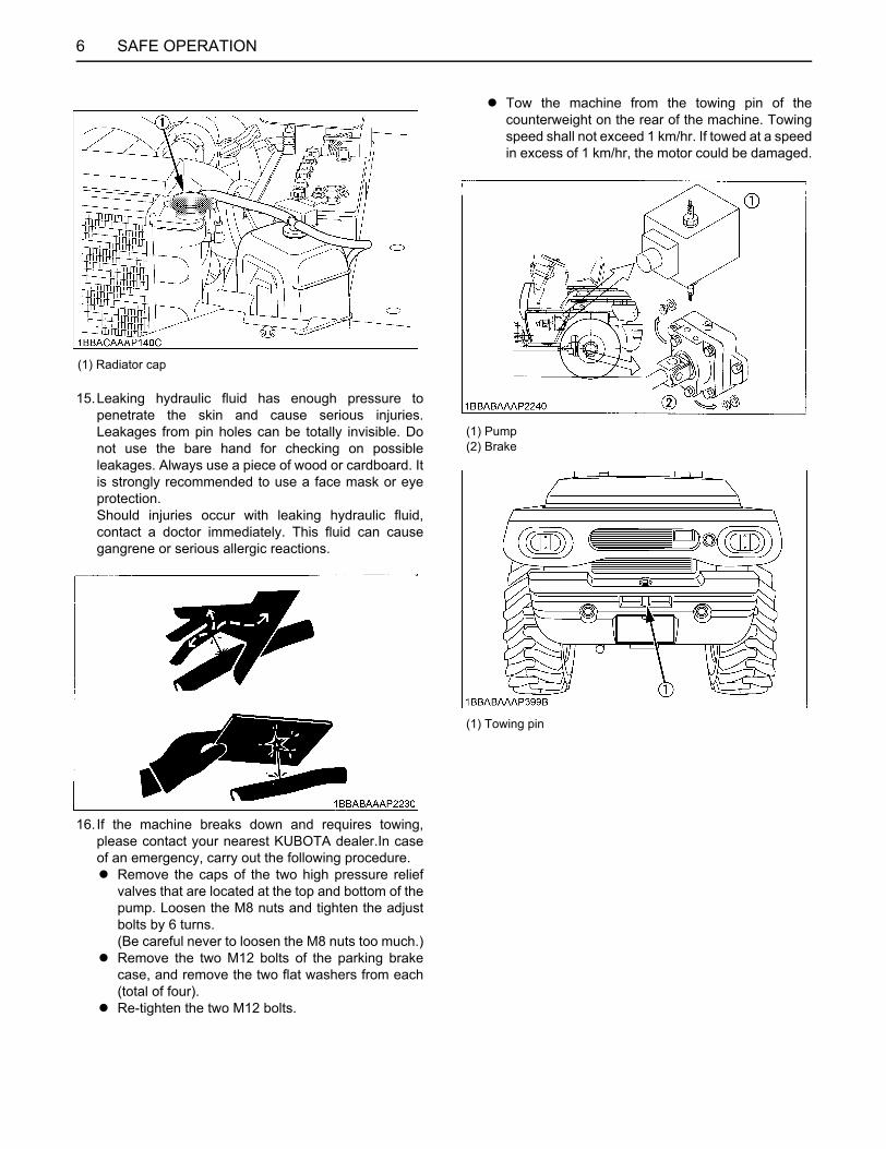
A Tow the machine from the towing pin of thecounterweight on the rear of the machine. Towingspeed shall not exceed 1 km/hr. If towed at a speedin excess of 1 km/hr, the motor could be damaged.
(1) Radiator cap
(1) Pump(2) Brake
(1) Towing pin
7SAFE OPERATION
17.Failure to follow proper procedures when mounting atire on a wheel or rim can produce an explosion whichmay result in serious injury or death. Do not attempt tomount a tire unless you have the proper equipmentand experience to perform the job. Have it done byyour KUBOTA dealer or a qualified tire repair service.
18.Use a face mask or eye protection to protect the eyesand respiratory system against dust and other foreignparticles.
SAFE OPERATION8
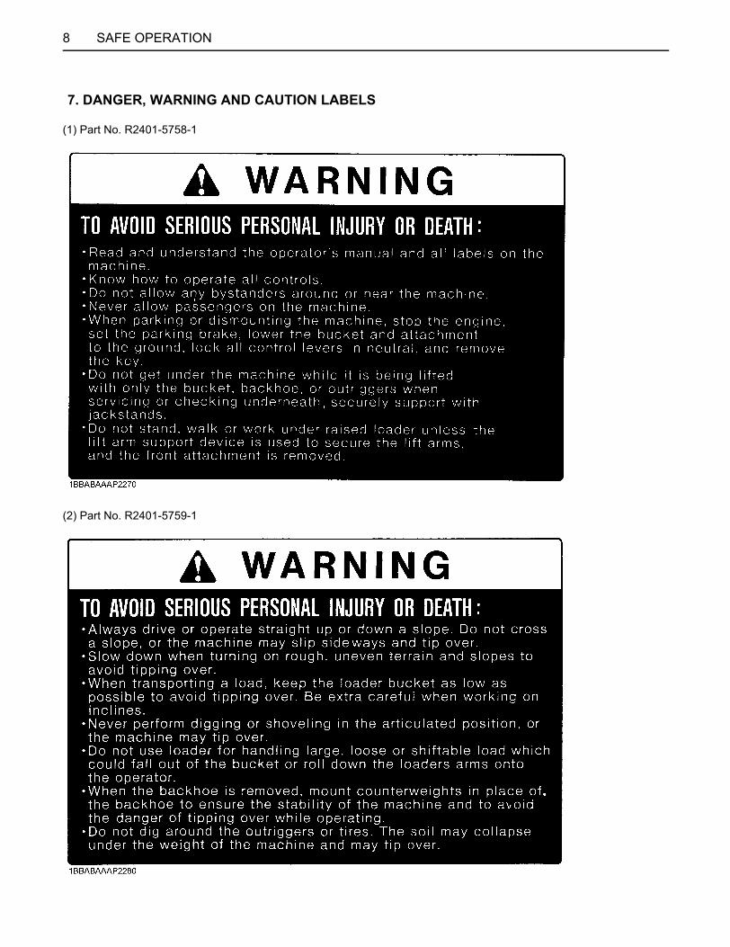
(1) Part No. R2401-5758-1
(2) Part No. R2401-5759-1
7. DANGER, WARNING AND CAUTION LABELS
9SAFE OPERATION
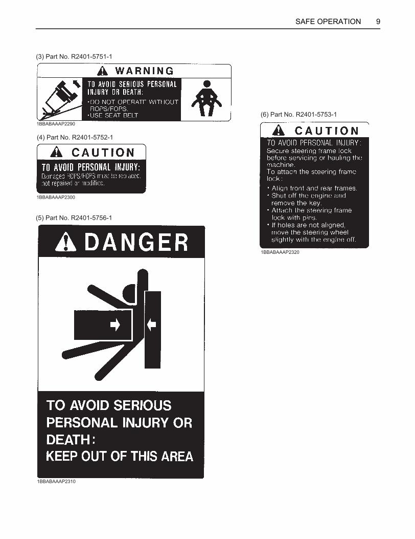
(3) Part No. R2401-5751-1
(4) Part No. R2401-5752-1
(6) Part No. R2401-5753-1
(5) Part No. R2401-5756-1
1BBABAAAP2290
1BBABAAAP2300
1BBABAAAP2310
1BBABAAAP2320
SAFE OPERATION10
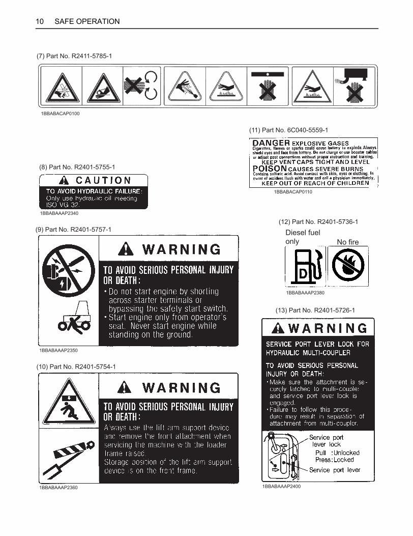
1BBABAAAP2380
(13) Part No. R2401-5726-1
(10) Part No. R2401-5754-1
(9) Part No. R2401-5757-1(12) Part No. R2401-5736-1
Diesel fuel only No fire
1BBABAAAP2350
1BBABAAAP2360 1BBABAAAP2400
(8) Part No. R2401-5755-1
(11) Part No. 6C040-5559-1
(7) Part No. R2411-5785-1
1BBABAAAP2340
1BBABACAP0100
1BBABACAP0110

11SAFE OPERATION

SAFE OPERATION12
1. Keep danger, warning and caution labels clean and free from obstructing material.2. Clean danger, warning and caution labels with soap and water, dry with a soft cloth.3. Replace damaged or missing danger, warning and caution labels with new labels from your local KUBOTA dealer.4. If a component with danger, warning and caution label (s) affixed is replaced with new part, make sure new label (s) is
(are) attached in the same location (s) as the replaced component.5. Mount new danger, warning and caution labels by applying on a clean dry surface and pressing any bubbles to outside
edge.
8. CARE OF DANGER, WARNING AND CAUTION LABELS
1SERVICING OF WHEEL LOADER
SERVICING OF WHEEL LOADER
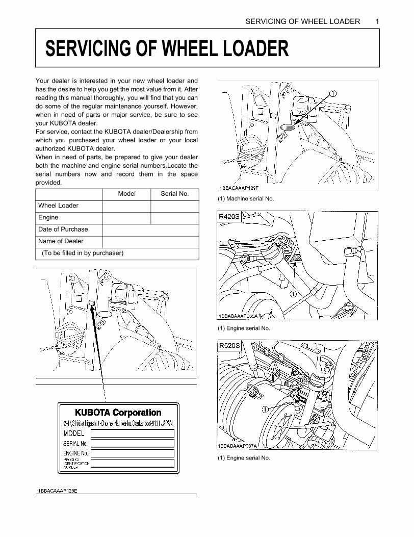
Your dealer is interested in your new wheel loader andhas the desire to help you get the most value from it. Afterreading this manual thoroughly, you will find that you cando some of the regular maintenance yourself. However,when in need of parts or major service, be sure to seeyour KUBOTA dealer.For service, contact the KUBOTA dealer/Dealership fromwhich you purchased your wheel loader or your localauthorized KUBOTA dealer.When in need of parts, be prepared to give your dealerboth the machine and engine serial numbers.Locate theserial numbers now and record them in the spaceprovided.Model Serial No.
Wheel Loader
Engine
Date of Purchase
Name of Dealer
(To be filled in by purchaser)
(1) Machine serial No.
(1) Engine serial No.
(1) Engine serial No.
2 SPECIFICATIONS
SPECIFICATIONS
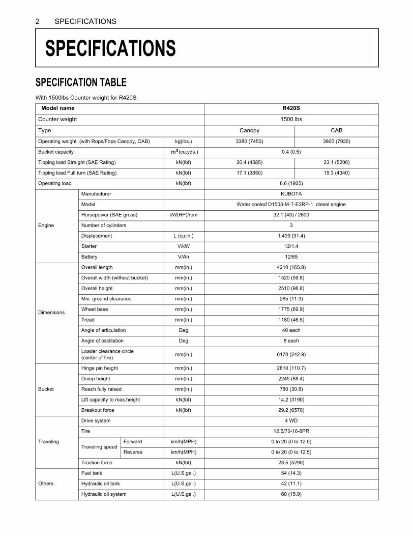
SPECIFICATION TABLEWith 1500lbs Counter weight for R420S.Model name R420S
Counter weight 1500 lbs
Type Canopy CAB
Operating weight (with Rops/Fops Canopy, CAB) kg(lbs.) 3380 (7450) 3600 (7935)
Bucket capacity (cu.yds.) 0.4 (0.5)
Tipping load Straight (SAE Rating) kN(lbf) 20.4 (4585) 23.1 (5200)
Tipping load Full turn (SAE Rating) kN(lbf) 17.1 (3850) 19.3 (4340)
Operating load kN(lbf) 8.6 (1925)
Engine
Manufacturer KUBOTA
Model Water cooled D1503-M-T-E2RP-1 diesel engine
Horsepower (SAE gross) kW(HP)/rpm 32.1 (43) / 2600
Number of cylinders 3
Displacement L (cu.in.) 1.499 (91.4)
Starter V/kW 12/1.4
Battery V/Ah 12/65
Dimensions
Overall length mm(in.) 4210 (165.8)
Overall width (without bucket) mm(in.) 1520 (59.8)
Overall height mm(in.) 2510 (98.8)
Min. ground clearance mm(in.) 285 (11.3)
Wheel base mm(in.) 1775 (69.9)
Tread mm(in.) 1180 (46.5)
Angle of articulation Deg 40 each
Angle of oscillation Deg 8 each
Loader clearance circle (center of tire) mm(in.) 6170 (242.9)
Bucket
Hinge pin height mm(in.) 2810 (110.7)
Dump height mm(in.) 2245 (88.4)
Reach fully raised mm(in.) 780 (30.8)
Lift capacity to max.height kN(lbf) 14.2 (3190)
Breakout force kN(lbf) 29.2 (6570)
Traveling
Drive system 4 WD
Tire 12.5/70-16-8PR
Traveling speedForward km/h(MPH) 0 to 20 (0 to 12.5)
Reverse km/h(MPH) 0 to 20 (0 to 12.5)
Traction force kN(lbf) 23.5 (5290)
Others
Fuel tank L(U.S.gal.) 54 (14.3)
Hydraulic oil tank L(U.S.gal.) 42 (11.1)
Hydraulic oil system L(U.S.gal.) 60 (15.9)
3SPECIFICATIONS
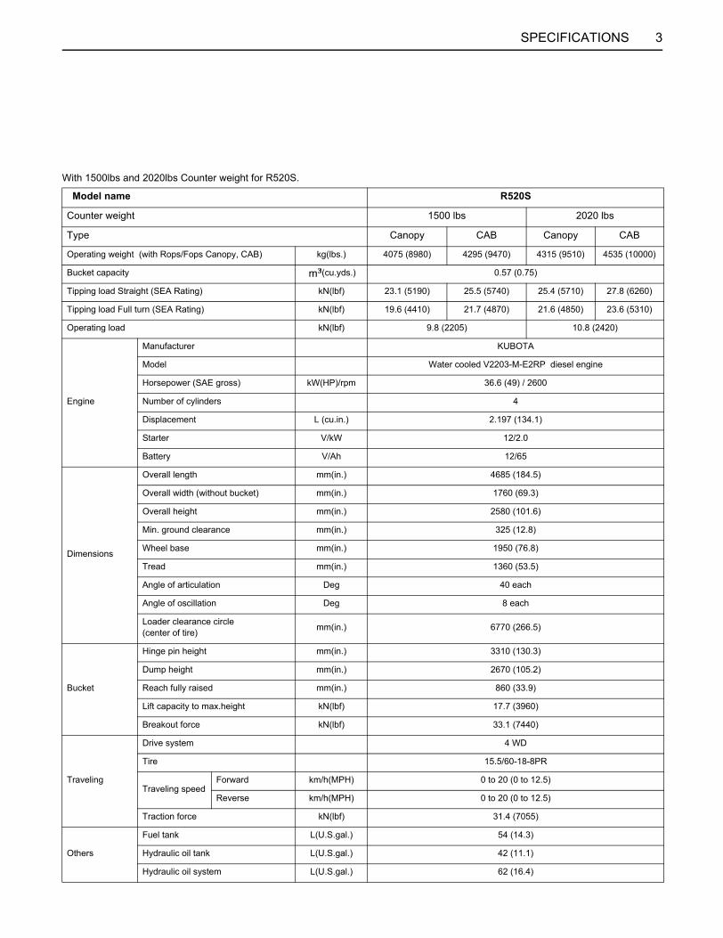
With 1500lbs and 2020lbs Counter weight for R520S.
Model name R520S
Counter weight 1500 lbs 2020 lbs
Type Canopy CAB Canopy CAB
Operating weight (with Rops/Fops Canopy, CAB) kg(lbs.) 4075 (8980) 4295 (9470) 4315 (9510) 4535 (10000)
Bucket capacity (cu.yds.) 0.57 (0.75)
Tipping load Straight (SEA Rating) kN(lbf) 23.1 (5190) 25.5 (5740) 25.4 (5710) 27.8 (6260)
Tipping load Full turn (SEA Rating) kN(lbf) 19.6 (4410) 21.7 (4870) 21.6 (4850) 23.6 (5310)
Operating load kN(lbf) 9.8 (2205) 10.8 (2420)
Engine
Manufacturer KUBOTA
Model Water cooled V2203-M-E2RP diesel engine
Horsepower (SAE gross) kW(HP)/rpm 36.6 (49) / 2600
Number of cylinders 4
Displacement L (cu.in.) 2.197 (134.1)
Starter V/kW 12/2.0
Battery V/Ah 12/65
Dimensions
Overall length mm(in.) 4685 (184.5)
Overall width (without bucket) mm(in.) 1760 (69.3)
Overall height mm(in.) 2580 (101.6)
Min. ground clearance mm(in.) 325 (12.8)
Wheel base mm(in.) 1950 (76.8)
Tread mm(in.) 1360 (53.5)
Angle of articulation Deg 40 each
Angle of oscillation Deg 8 each
Loader clearance circle (center of tire) mm(in.) 6770 (266.5)
Bucket
Hinge pin height mm(in.) 3310 (130.3)
Dump height mm(in.) 2670 (105.2)
Reach fully raised mm(in.) 860 (33.9)
Lift capacity to max.height kN(lbf) 17.7 (3960)
Breakout force kN(lbf) 33.1 (7440)
Traveling
Drive system 4 WD
Tire 15.5/60-18-8PR
Traveling speedForward km/h(MPH) 0 to 20 (0 to 12.5)
Reverse km/h(MPH) 0 to 20 (0 to 12.5)
Traction force kN(lbf) 31.4 (7055)
Others
Fuel tank L(U.S.gal.) 54 (14.3)
Hydraulic oil tank L(U.S.gal.) 42 (11.1)
Hydraulic oil system L(U.S.gal.) 62 (16.4)

4 SPECIFICATIONS
Above dimensions are based on the machine with JPN ROPS/FOPS Canopy and ROPS/FOPS CAB.JPN = made in JapanMean Value and value for use on concrete roads are given for tipping load and operating load.Specifications Subject to change without Notice.
5INSTRUMENT PANEL AND CONTROLS
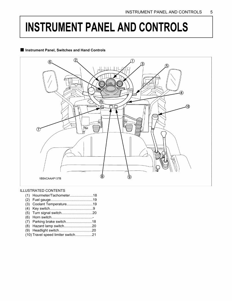
INSTRUMENT PANEL AND CONTROLS
B Instrument Panel, Switches and Hand ControlsILLUSTRATED CONTENTS(1) Hourmeter/Tachometer.......................18(2) Fuel gauge..........................................19(3) Coolant Temperature..........................19(4) Key switch...........................................9(5) Turn signal switch...............................20(6) Horn switch.........................................-(7) Parking brake switch..........................18(8) Hazard lamp switch............................20(9) Headlight switch.................................20(10) Travel speed limiter switch.................21
6 INSTRUMENT PANEL AND CONTROLS
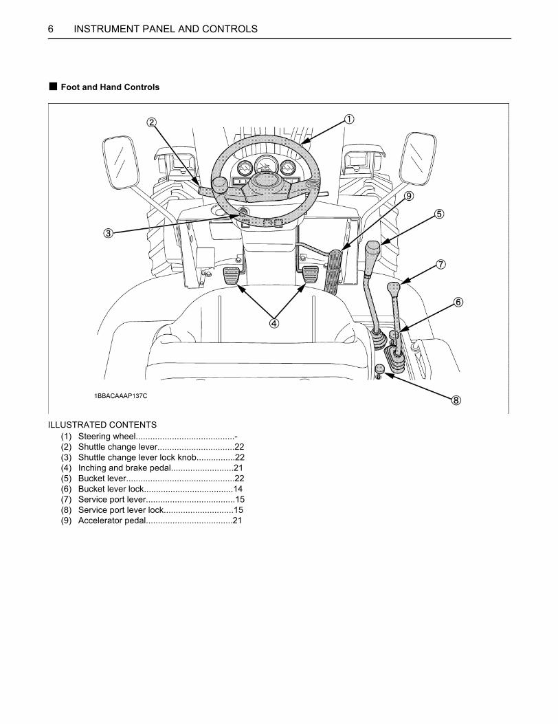
B Foot and Hand Controls
ILLUSTRATED CONTENTS(1) Steering wheel.........................................-(2) Shuttle change lever................................22(3) Shuttle change lever lock knob................22(4) Inching and brake pedal..........................21(5) Bucket lever.............................................22(6) Bucket lever lock.....................................14(7) Service port lever.....................................15(8) Service port lever lock.............................15(9) Accelerator pedal....................................21
7INSTRUMENT PANEL AND CONTROLS
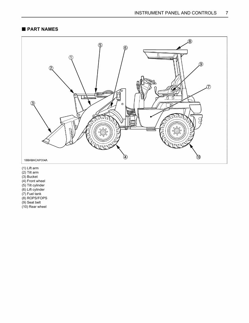
B PART NAMES
(1) Lift arm(2) Tilt arm(3) Bucket(4) Front wheel(5) Tilt cylinder(6) Lift cylinder(7) Fuel tank(8) ROPS/FOPS(9) Seat belt(10) Rear wheel
8 INSTRUMENT PANEL AND CONTROLS
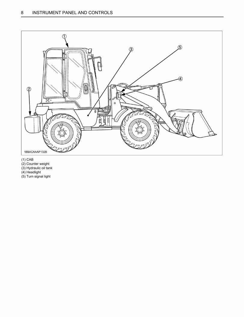
(1) CAB(2) Counter weight(3) Hydraulic oil tank(4) Headlight(5) Turn signal light
9OPERATING THE ENGINE
OPERATING THE ENGINE
To avoid personal injury or death:A Read "Safe Operation" in the front of this
manual.A Read the Danger, Warning, Caution labels
located on the machine and attachment.A To avoid the danger of exhaust fume
poisoning, do not operate the engine in aclosed building without proper ventilation.
A Never start engine while standing on ground.Start engine only from operator's seat.
A Do not start the engine by shorting acrossstarter terminals.
A Do not turn off the starter switch whiletraveling. If turning off the switch, the machine stopsabruptly.
DAILY CHECKTo prevent the trouble, it is important to know theconditions of the machine well.Check it before starting.
To avoid personal injury:A Be sure to check and service the machine on a
level surface with the engine shut off and theparking brake "ON".
Check itemSee "DAILY CHECK" in the MAINTENANCE section.
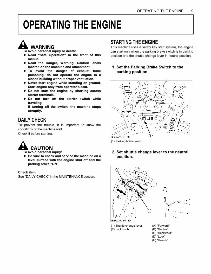
STARTING THE ENGINEThis machine uses a safety key start system, the enginecan start only when the parking brake switch is in parkingposition and the shuttle change lever in neutral position.
1. Set the Parking Brake Switch to the parking position.
(1) Parking brake switch
2. Set shuttle change lever to the neutral position.
(1) Shuttle change lever(2) Lock knob
(A) "Forward"(B) "Neutral"(C) "Backward"(D) "Lock"(E) "Unlock"
OPERATING THE ENGINE10
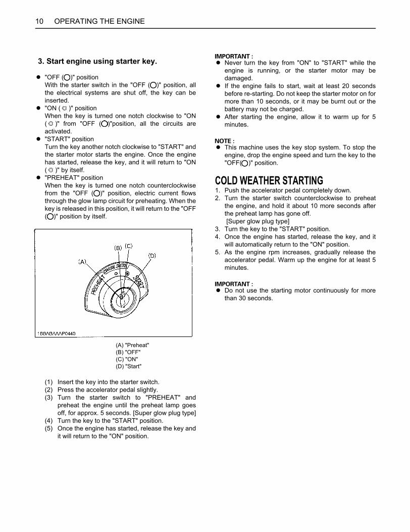
A "OFF ( )" positionWith the starter switch in the "OFF ( )" position, allthe electrical systems are shut off, the key can beinserted.
A "ON ( )" positionWhen the key is turned one notch clockwise to "ON( )" from "OFF ( )"position, all the circuits areactivated.
A "START" positionTurn the key another notch clockwise to "START" andthe starter motor starts the engine. Once the enginehas started, release the key, and it will return to "ON( )" by itself.
A "PREHEAT" positionWhen the key is turned one notch counterclockwisefrom the "OFF ( )" position, electric current flowsthrough the glow lamp circuit for preheating. When thekey is released in this position, it will return to the "OFF( )" position by itself.
(1) Insert the key into the starter switch.(2) Press the accelerator pedal slightly.(3) Turn the starter switch to "PREHEAT" and
preheat the engine until the preheat lamp goesoff, for approx. 5 seconds. [Super glow plug type]
(4) Turn the key to the "START" position.(5) Once the engine has started, release the key and
it will return to the "ON" position.
A Never turn the key from "ON" to "START" while theengine is running, or the starter motor may bedamaged.
A If the engine fails to start, wait at least 20 secondsbefore re-starting. Do not keep the starter motor on formore than 10 seconds, or it may be burnt out or thebattery may not be charged.
A After starting the engine, allow it to warm up for 5minutes.
A This machine uses the key stop system. To stop theengine, drop the engine speed and turn the key to the"OFF( )" position.
COLD WEATHER STARTING1. Push the accelerator pedal completely down.2. Turn the starter switch counterclockwise to preheat
the engine, and hold it about 10 more seconds afterthe preheat lamp has gone off. [Super glow plug type]
3. Turn the key to the "START" position.4. Once the engine has started, release the key, and it
will automatically return to the "ON" position.5. As the engine rpm increases, gradually release the
accelerator pedal. Warm up the engine for at least 5minutes.
A Do not use the starting motor continuously for morethan 30 seconds.
3. Start engine using starter key.
(A) "Preheat"(B) "OFF"(C) "ON"(D) "Start"
11OPERATING THE ENGINE
CHECKS IMMEDIATELY AFTER ENGINE START1. If the engine or hydraulic oil is cold, the machine will
not work at its best. When warming up the engine, donot quickly accelerate the engine.
2. Once the engine has been warmed up, check to seeA That the engine oil pressure alarm lamp is off.A That the battery charge lamp goes off when engine
speed is increased.A That the color of exhaust is normal, and no unusual
noise or vibrations are observed.A That no lubricant, fuel or water is leaking.
C If one of the following should be found,immediately stop the engine.
A Engine speed suddenly decreases or increases.A Sudden, abnormal noise is heard.A Color of exhaust is dark.A The engine oil pressure alarm lamp lights up during
operation.A LST filter warning lamp lights up during operation.
A Check and maintain the machine, following thedirections from your KUBOTA dealer.
STOPPING THE ENGINE
To avoid personal injury or death:A When dismounting the machine, stop the
engine, set the shuttle change lever to theneutral position and set the parking brakeswitch to the parking position, lower the bucketand attachment to the ground, release thehydraulic pressure in the hydraulic system byoperating control levers, lock all control leversin neutral, and remove the key.
1. Idle the engine for about five minutes to allow it to cool.2. By turning the key to the "OFF ( )" position, the
engine stops.3. Slowly operate the bucket control levers to place the
bucket on the ground.
A Do not stop the engine before it cools sufficiently, orthe service life of the engine parts may be shortened.
A If the engine overheats, do not stop it immediately butcool it gradually by running it at medium speed beforestopping.
OPERATING THE ENGINE12
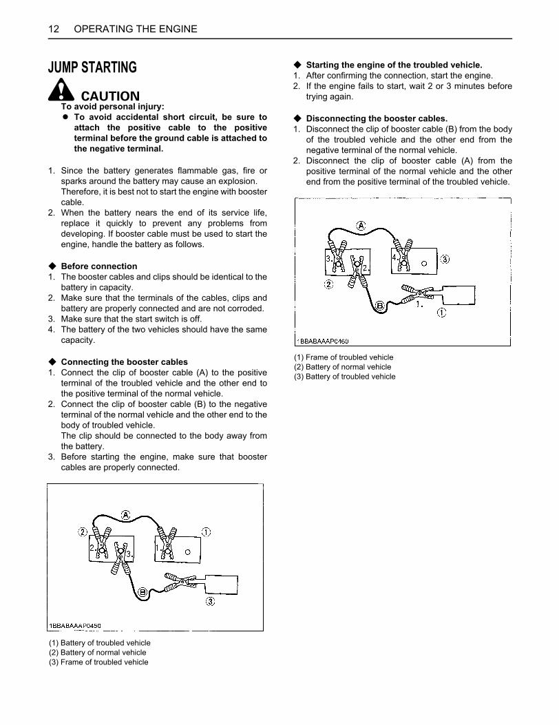
JUMP STARTING
To avoid personal injury:A To avoid accidental short circuit, be sure to
attach the positive cable to the positiveterminal before the ground cable is attached tothe negative terminal.
1. Since the battery generates flammable gas, fire orsparks around the battery may cause an explosion. Therefore, it is best not to start the engine with boostercable.
2. When the battery nears the end of its service life,replace it quickly to prevent any problems fromdeveloping. If booster cable must be used to start theengine, handle the battery as follows.
C Before connection1. The booster cables and clips should be identical to the
battery in capacity.2. Make sure that the terminals of the cables, clips and
battery are properly connected and are not corroded.3. Make sure that the start switch is off.4. The battery of the two vehicles should have the same
capacity.
C Connecting the booster cables1. Connect the clip of booster cable (A) to the positive
terminal of the troubled vehicle and the other end tothe positive terminal of the normal vehicle.
2. Connect the clip of booster cable (B) to the negativeterminal of the normal vehicle and the other end to thebody of troubled vehicle. The clip should be connected to the body away fromthe battery.
3. Before starting the engine, make sure that boostercables are properly connected.
C Starting the engine of the troubled vehicle.1. After confirming the connection, start the engine.2. If the engine fails to start, wait 2 or 3 minutes before
trying again.
C Disconnecting the booster cables.1. Disconnect the clip of booster cable (B) from the body
of the troubled vehicle and the other end from thenegative terminal of the normal vehicle.
2. Disconnect the clip of booster cable (A) from thepositive terminal of the normal vehicle and the otherend from the positive terminal of the troubled vehicle.
(1) Battery of troubled vehicle(2) Battery of normal vehicle(3) Frame of troubled vehicle
(1) Frame of troubled vehicle(2) Battery of normal vehicle(3) Battery of troubled vehicle
13OPERATING THE MACHINE
OPERATING THE MACHINE
HOW TO USE A NEW MACHINEA new machine has been carefully tested and inspected,and various adjustments have been made in the factory.However, you can say that the machine is the same as anewly born baby as the machine should be handled withthe greatest care during the first 100 hours.The life of the machine is greatly affected by how themachine has been used during the initial 100 hours.STARTING
To avoid personal injury:A Make sure that the engine cover is completely
latched.
To avoid personal injury:A Make sure that the seat is completely secured
after each adjustment.A Do not allow any person other than the driver to
ride on the machine.
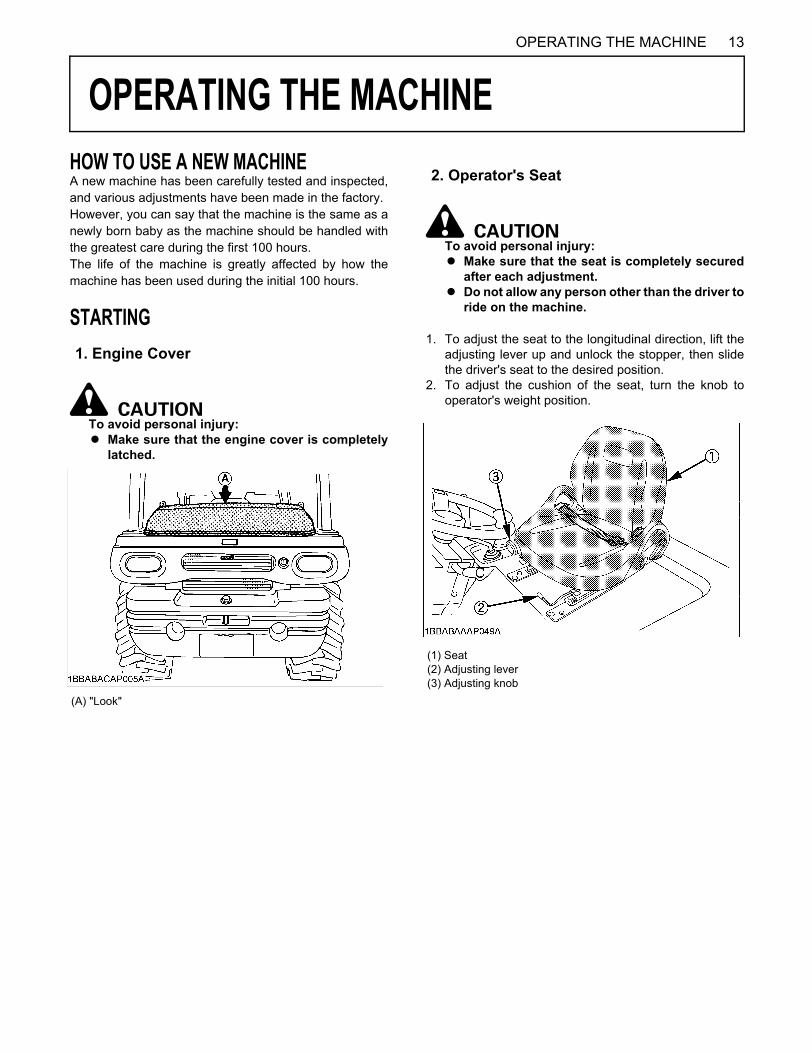
1. To adjust the seat to the longitudinal direction, lift theadjusting lever up and unlock the stopper, then slidethe driver's seat to the desired position.
2. To adjust the cushion of the seat, turn the knob tooperator's weight position.
1. Engine Cover
(A) "Look"
2. Operator's Seat
(1) Seat(2) Adjusting lever(3) Adjusting knob
OPERATING THE MACHINE14
To avoid personal injury:A Never operate the machine without ROPS/
FOPS and Seat Belt.A Always use the seat belt before you start the
engine.
SAFETY LEVERS AND APPLIANCEBSafety Key Start SystemThis is the safety system to prevent the machine frommoving suddenly.The parking brake switch is to be set to the parkingposition and the shuttle change lever is to be set to theneutral position before stopping the engine.The safety key start system does not allow the engine tostart when the parking switch is out of the parking position,and the shuttle change lever is out of the neutral position.
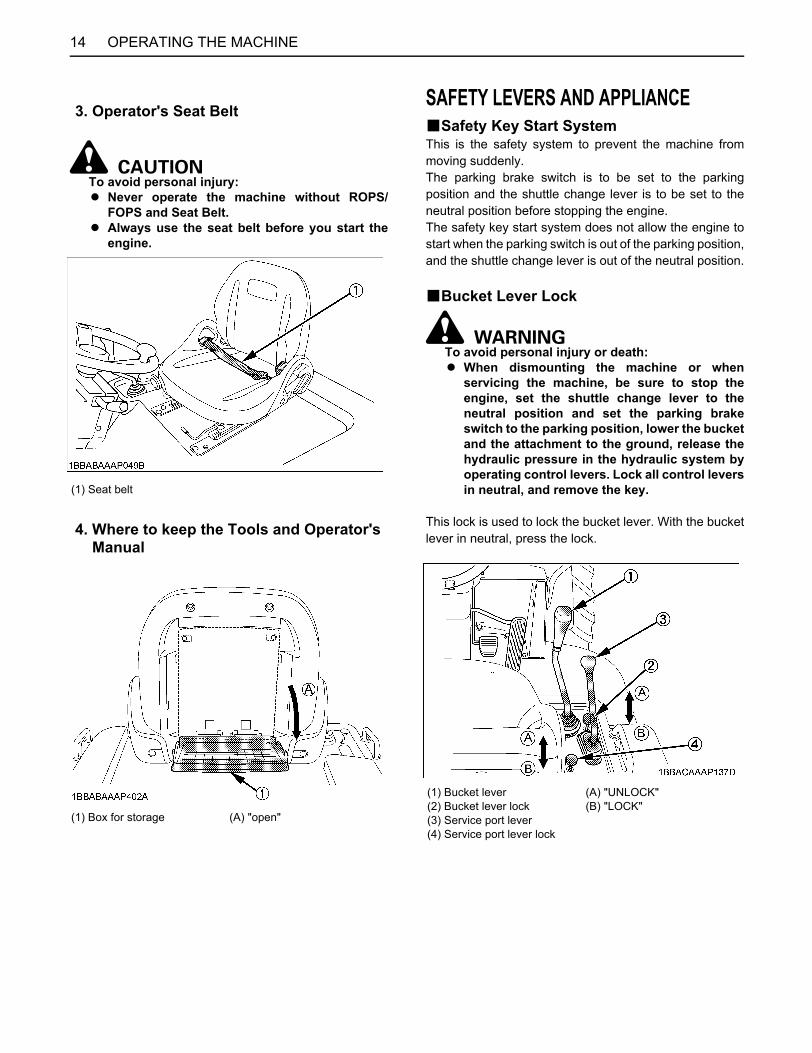
BBucket Lever Lock
To avoid personal injury or death:A When dismounting the machine or when
servicing the machine, be sure to stop theengine, set the shuttle change lever to theneutral position and set the parking brakeswitch to the parking position, lower the bucketand the attachment to the ground, release thehydraulic pressure in the hydraulic system byoperating control levers. Lock all control leversin neutral, and remove the key.
This lock is used to lock the bucket lever. With the bucketlever in neutral, press the lock.
3. Operator's Seat Belt
(1) Seat belt
4. Where to keep the Tools and Operator's Manual
(1) Box for storage (A) "open"
(1) Bucket lever(2) Bucket lever lock(3) Service port lever(4) Service port lever lock
(A) "UNLOCK"(B) "LOCK"
15OPERATING THE MACHINE
BService Port Lever Lock
To avoid personal injury or death:A When dismounting the machine or when
servicing the machine, be sure to stop theengine, set the shuttle change lever to theneutral position and set the parking brakeswitch to the parking position, lower the bucketand the attachment to the ground, release thehydraulic pressure in the hydraulic system byoperating control levers. Lock all control leversin neutral, and remove the key.
A In case of the service port lever is used for thehydraulic quick coupler, always lock theservice port lever after installing frontattachment (bucket etc.) to the hydraulic quickcoupler. If the machine is operated without thelock, it causes sever injury or death.
This lock is used to lock the service port lever. With theservice port lever in neutral, press the lock.
BLift Arm Support
To avoid personal injury or death:A Before installing the lift arm support, remove
the front attachment set the shuttle changelever to the neutral position and the parkingbrake switch to the parking position, lock allcontrol levers in neutral, and remove the key.
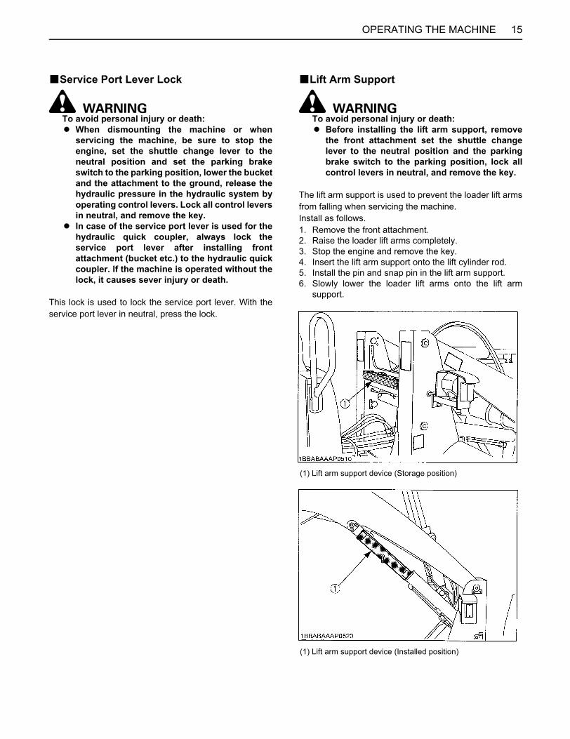
The lift arm support is used to prevent the loader lift armsfrom falling when servicing the machine.Install as follows.1. Remove the front attachment. 2. Raise the loader lift arms completely.3. Stop the engine and remove the key.4. Insert the lift arm support onto the lift cylinder rod.5. Install the pin and snap pin in the lift arm support.6. Slowly lower the loader lift arms onto the lift arm
support.
(1) Lift arm support device (Storage position)
(1) Lift arm support device (Installed position)
OPERATING THE MACHINE16
BRoll-Over Protective Structures (ROPS) / Falling Objective Protective Structures (FOPS)
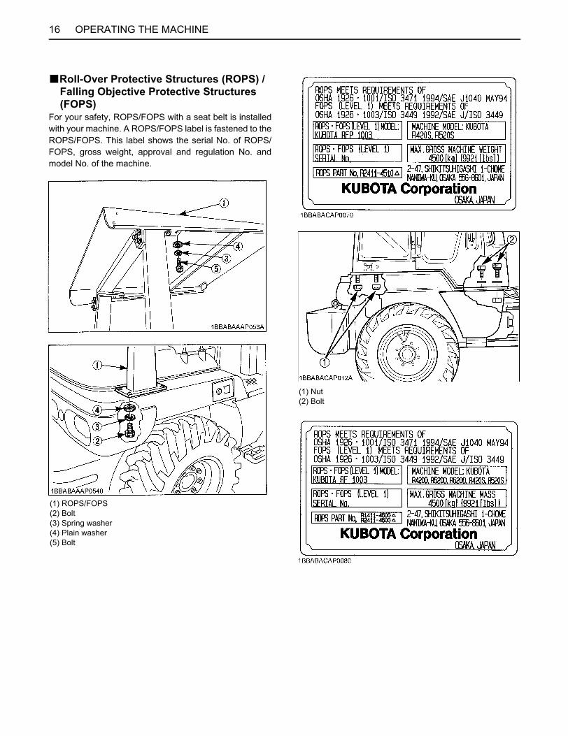
For your safety, ROPS/FOPS with a seat belt is installedwith your machine. A ROPS/FOPS label is fastened to theROPS/FOPS. This label shows the serial No. of ROPS/FOPS, gross weight, approval and regulation No. andmodel No. of the machine.
(1) ROPS/FOPS(2) Bolt(3) Spring washer(4) Plain washer(5) Bolt
(1) Nut(2) Bolt
17OPERATING THE MACHINE
To avoid personal injury or death:A Always use a ROPS/FOPS with seat belt, when
driving or operating the machine. Do notmodify a ROPS/FOPS in any way. Welding,bending, drilling or cutting any portion of theROPS/FOPS may weaken the structure. Do notrepair a damaged ROPS/FOPS. A damagedROPS/FOPS structure must be replaced, notrepaired or revised. If any structural member ofthe ROPS/FOPS is damaged, replace the entirestructure at your local KUBOTA dealer. Checkthe seat belt daily and replace it if damaged orfrayed.
A Do not remove the ROPS/FOPS except forservice. Install the ROPS/FOPS correctlybefore you operate the machine again.
A Do not install any attachments that will causethe total gross weight of the machine to exceedthe weight shown in the "FOR MAXIMUMGROSS MACHINE WEIGHT" space on theROPS/FOPS label.
CAB
BSteering Frame Lock
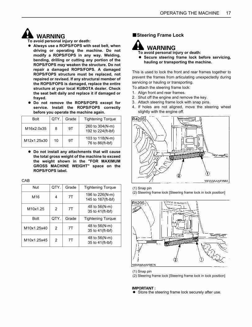
To avoid personal injury or death:A Secure steering frame lock before servicing,
hauling or transporting the machine.
This is used to lock the front and rear frames together toprevent the frames from articulating unexpectedly duringservicing or hauling or transporting.To attach the steering frame lock:1. Align front and rear frames.2. Shut off the engine and remove the key.3. Attach steering frame lock with snap pins.4. If holes are not aligned, move the steering wheel
slightly with the engine off.
A Store the steering frame lock securely after use.
Bolt QTY. Grade Tightening Torque
M16x2.0x35 8 9T 260 to 304(N-m) 192 to 224(ft-lbf)
M12x1.25x30 10 9T 103 to 118(N-m) 76 to 86(ft-lbf)
Nut QTY. Grade Tightening Torque
M16 4 7T 196 to 226(N-m) 145 to 167(ft-lbf)
M10x1.25 2 7T 48 to 56(N-m) 35 to 41(ft-lbf)
Bolt QTY. Grade Tightening Torque
M10x1.25x40 2 7T 48 to 56(N-m) 35 to 41(ft-lbf)
M10x1.25x45 2 7T 48 to 56(N-m) 35 to 41(ft-lbf)
(1) Snap pin(2) Steering frame lock [Steering frame lock in lock position]
(1) Snap pin(2) Steering frame lock [Steering frame lock in lock position]
OPERATING THE MACHINE18
BParking Brake Switch
To avoid personal injury or death:A When dismounting the machine or when
servicing or hauling, be sure to apply theparking brake.
A Make sure that the shuttle change lever is in theneutral position and the parking brake switch isat the parking position before starting theengine. To prevent the machine from starting suddenlyand unexpectedly, the safety key start systemis provided. The engine can start only when the shuttlechange lever is in the neutral position and theparking brake switch is at the parking position.
The parking brake is to be used when parking themachine.
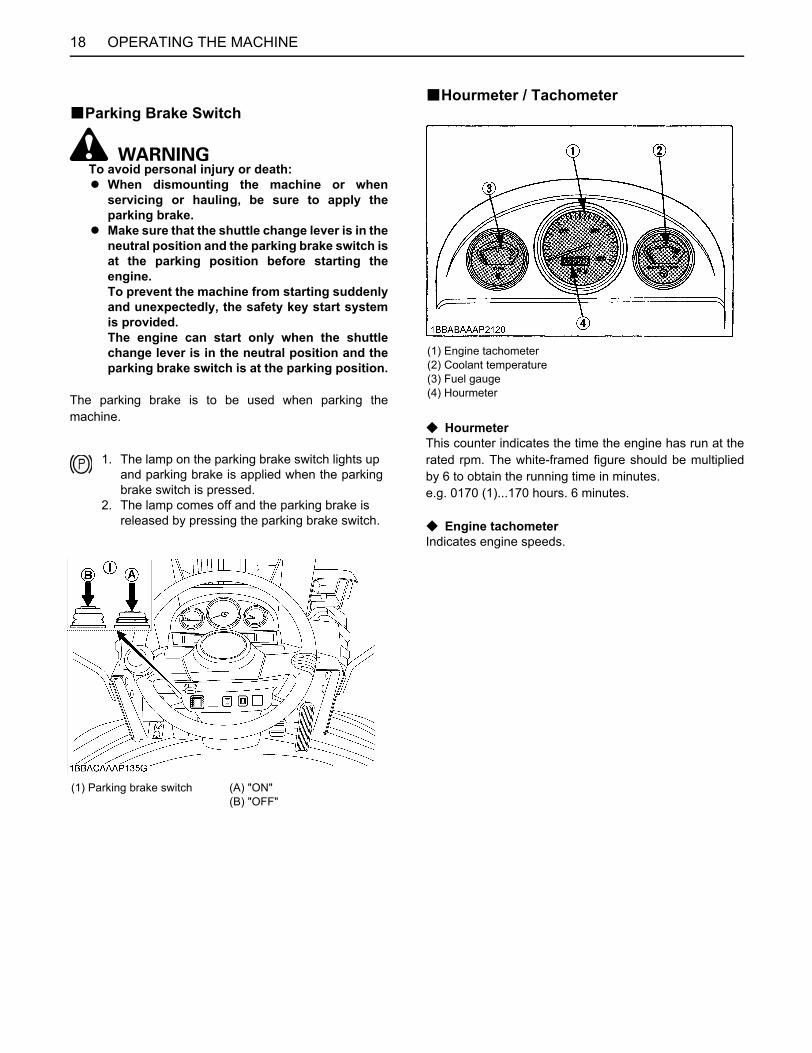
BHourmeter / Tachometer
C HourmeterThis counter indicates the time the engine has run at therated rpm. The white-framed figure should be multipliedby 6 to obtain the running time in minutes.e.g. 0170 (1)...170 hours. 6 minutes.
C Engine tachometerIndicates engine speeds.
1. The lamp on the parking brake switch lights up and parking brake is applied when the parkingbrake switch is pressed.
2. The lamp comes off and the parking brake is released by pressing the parking brake switch.
(1) Parking brake switch (A) "ON"(B) "OFF"
(1) Engine tachometer(2) Coolant temperature(3) Fuel gauge(4) Hourmeter
19OPERATING THE MACHINE
BFuel GaugeWith the starter switch in the "ON( )" position.Fuel level meter indicates the remaining fuel.
A Refuel before the meter points to the E mark. If the fuelsystem is allowed to go empty, air-bleeding will benecessary.
BCoolant TemperatureWith the starter switch in the "ON ( )" position, itindicates engine coolant temperature. The symbol Cstands for cool and the symbol H, hot.
A When the pointer deflects across the bold line on theside of the H range, immediately stop the engine andcheck the following:1) lack or leaking of coolant.2) fan belt tension.3) mud and dirt deposits between the radiator fins.
A When the engine overheats.1) Stop the operation.2) Idle the engine for about 5 minutes.3) Stop the engine and check.
BEasy Checker
Travel speed limiter lampThis lamp lights up when the travel speedlimiter switch is pressed.Engine oil pressure alarm lampThis lamp lights up if the engine oil iscirculating abnormally.This lamp lights up with the starter switch inthe "ON ( )" position and it is put out as soonas the engine starts.If the lamp stays on after the engine hasstarted, check the engine lubricant level.
Battery charge lampThis lamp lights up if the battery chargesystem is abnormal.This lamp lights up when turning the starterswitch to the "ON ( )" position and goes offwhen the engine has started.
Glow lampThis lamp lights for five seconds when thestarter switch is turned to the "PREHEAT"position, or from "ON ( )" to "START".
LST oil temperature alarm lampThis lamp lights up when the oil temperaturebecomes out of the range.Once the lamp lights up, stop working andwait while idling the engine until it goes off.LST oil pressure lampThis lamp lights up when turning the starterswitch to the "ON ( )" position and goes offwhen the engine has started.
A Carry out routine checks sufficiently. It is not safe to perform checks with easy checker only.
OPERATING THE MACHINE20
BTurn Signal SwitchOperate the turn signal switch to the right or left accordingto the direction in which the machine is to be turned. Thecorresponding turn signal will blink.Be sure to return the switch to the center position after theturn.
BHeadlight Switch
To avoid personal injury:A For night operation, keep all machine mounted
lights operating. Check for burned out lightsand replace immediately.
With the starter switch in the "ON" position, press theheadlight switch for the headlights.
BHazard Lamp SwitchPress the hazard lamp switch for the hazard lamps toblink.
BFuse BoxThe fuse box houses fuse for protection of the electricalcircuit. There are six 5 ampere fuses and six 10 amperefuses in the fuse box.There are also extra fuses provided.
(1) Turn signal switch (A) To blink left turn signal(B) To blink light turn signal
(1) Headlight switch (A) "ON"(B) "OFF"
(1) Hazard lamp switch (A) To blink the hazard lamp(B) "OFF"
(1) Fuse box
21OPERATING THE MACHINE
CONTROL LEVERS AND PEDALSBAccelerator PedalThis pedal controls engine rpm. The more the pedal ispressed, the greater the engine rpm.
A When the pedal is released, the engine speed willdrop.
A The engine rpm suitable for starting the machine on aplain ground is about 1,000 to 1,200 rpm, thoughdepending on the situations; i.e. ground condition,weather, etc. Press the accelerator pedal gradually when startingthe machine.
BInching and Brake PedalsThe inching and brake pedal are interlocked with eachother.The brake functions in the same way when either ispressed down.Press either pedal down slightly, then the LST pumpcomes in neutral and cuts off the engine power on the wayof the transmission, that is so-called dynamic brake,unique to LST (Load Sensing Transmission).When pressing it further, the disc brake acts together toobtain strong braking effect.For the details of inching and brake pedal, refer to thesection "How to use the inching pedal".
BTravel Speed Limiter Switch
To avoid personal injury or death:A While descending a slope in the high speed, be
extremely careful when applying the travelspeed limiter range from the high speed, thereis the risk of the machine rear lifting whichcould be dangerous.
A When descending a slope, use the enginebrake to slow the machine.
(1) Accelerator pedal
(1) Inching and brake pedal
1. The lamp on the easy checker lights up and speed is limited to 0 to 5 km/h (0 to 3.1 MPH) when the switch is pressed.
2. The lamp comes off and gets maximum speed when the switch is pressed one more time.
OPERATING THE MACHINE22
BShuttle Change Lever
To avoid personal injury or death:A To prevent the machine from moving suddenly
or unexpectedly, be sure and push the lockknob to lock the shuttle change lever whenevergetting on or off.
This lever is used for changing the machine's runningdirection, forward or back.Pull the lock knob to unlock the shuttle change lever lockand push the shuttle change lever forward for forwarddirection and pull it back for reverse direction.
BBucket Lever
To avoid personal injury:A Do not use float position to lower the bucket
and attachment. The bucket and attachmentwill lower in response to control levermovement even when the engine is off.
A single lever controls all bucket and lift arm operations.(1) Lift arm up(N) Hold (neutral)(2) Lift arm down(3) Floating(A) Bucket dump(B) Bucket tilt
(1) Shuttle change lever(2) Lock knob
(A) "Forward"(B) "Neutral"(C) "Backward"(D) "Lock"(E) "Unlock"
(1) Bucket lever
(A) "Tilt"(B) "Dump"(C) "Up"(D) "Down"
23OPERATING THE MACHINE
CAB TYPE MACHINESBOpening/Closing of CAB Door(CAB type
only)1. To open the CAB door from outside, unlock the CAB
door with the CAB key and pull the knob. Open theCAB door fully, push on its end, and the CAB door willbe locked.
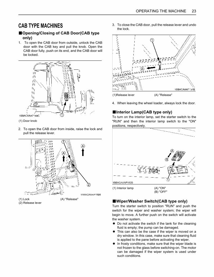
2. To open the CAB door from inside, raise the lock andpull the release lever.
3. To close the CAB door, pull the release lever and undothe lock.
4. When leaving the wheel loader, always lock the door.
BInterior Lamp(CAB type only)To turn on the interior lamp, set the starter switch to the"RUN" and then the interior lamp switch to the "ON"positions, respectively.
BWiper/Washer Switch(CAB type only)Turn the starter switch to position "RUN" and push theswitch for the wiper and washer system; the wiper willbegin to move. A further push on the switch will activatethe washer system.A Do not activate the switch if the tank for the cleaning
fluid is empty; the pump can be damaged.A This can also be the case if the wiper is moved on a
dry window. In this case, make sure that cleaning fluidis applied to the pane before activating the wiper.
A In frosty conditions, make sure that the wiper blade isnot frozen to the glass before switching-on. The motorcan be damaged if the wiper system is used undersuch conditions.
(1) Door knob
(1) Lock (A) "Release"(2) Release lever
(1)Release lever (A) "Release"
(1) Interior lamp (A) "ON"(B) "OFF"
OPERATING THE MACHINE24
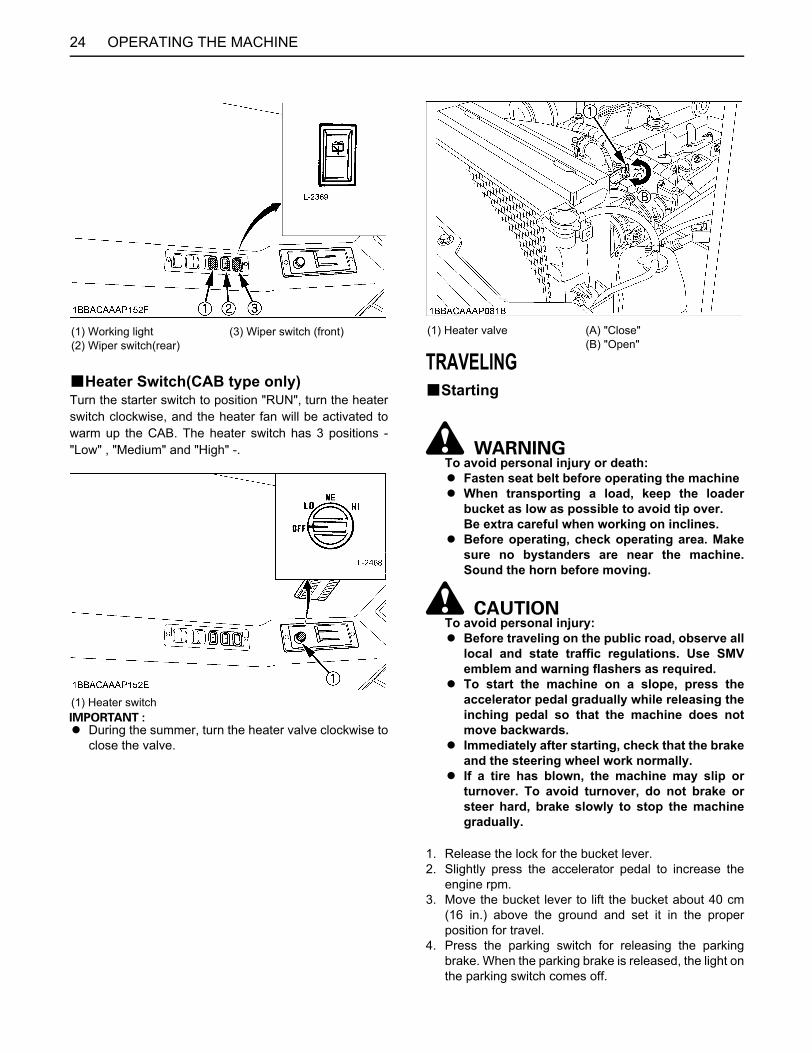
BHeater Switch(CAB type only)Turn the starter switch to position "RUN", turn the heaterswitch clockwise, and the heater fan will be activated towarm up the CAB. The heater switch has 3 positions -"Low" , "Medium" and "High" -.
A During the summer, turn the heater valve clockwise toclose the valve.
TRAVELINGBStarting
To avoid personal injury or death:A Fasten seat belt before operating the machineA When transporting a load, keep the loader
bucket as low as possible to avoid tip over. Be extra careful when working on inclines.
A Before operating, check operating area. Makesure no bystanders are near the machine.Sound the horn before moving.
To avoid personal injury:A Before traveling on the public road, observe all
local and state traffic regulations. Use SMVemblem and warning flashers as required.
A To start the machine on a slope, press theaccelerator pedal gradually while releasing theinching pedal so that the machine does notmove backwards.
A Immediately after starting, check that the brakeand the steering wheel work normally.
A If a tire has blown, the machine may slip orturnover. To avoid turnover, do not brake orsteer hard, brake slowly to stop the machinegradually.
1. Release the lock for the bucket lever.2. Slightly press the accelerator pedal to increase the
engine rpm.3. Move the bucket lever to lift the bucket about 40 cm
(16 in.) above the ground and set it in the properposition for travel.
4. Press the parking switch for releasing the parkingbrake. When the parking brake is released, the light onthe parking switch comes off.
(1) Working light (3) Wiper switch (front)(2) Wiper switch(rear)
(1) Heater switch
(1) Heater valve (A) "Close"(B) "Open"
25OPERATING THE MACHINE
5. Set the shuttle change lever to the desired position,gradually increase the engine rpm by pressing theaccelerator pedal and the machine will move.
BTurning
To avoid personal injury or death:A Do not turn sharply at high speeds. It is
dangerous. In the worst possible case, themachine may turn over.
A The steering wheel for this machine will notreturn of itself to the straight ahead positionafter turning. Be sure to return the wheel to thestraight ahead position.
A Steering lose will result if the engine is stoppedduring travel.Do not stop the engine during travel.
To steer the machine to either side, turn the steeringwheel in the intended direction.1. The front and rear frames of this machine bend at the
center pin (the pin connecting the two frames) so thatwhen the machine turns, the rear wheels follow thetracks of the front wheels.
2. Rotate the steering wheel to follow the turn of themachine. When turning fully, never attempt to rotatethe steering wheel once it reaches its full stroke.
BDeceleration on a Slope
To avoid personal injury or death:A Going up or down a slope diagonally is
dangerous as the machine may skid. Alwaysdrive or operate straight up or down a slope, orthe machine may slip side ways and tip over.
A Use foot brake together with engine brake if themachine tends to over-run when descending aslope.
To avoid personal injury:A If the engine should stall on a slope, set the
parking brake switch to the parking positionimmediately for safety purpose, although thedisc brake is automatically applied. Then set the shuttle change lever to the neutralposition to prepare for the next start.
A When descending down along slope, useengine brake. Using the foot brake aloneaccelerates brake pad wear and cause heatbuildup and will result in poor brakeperformance.
BTraveling on rough roads
To avoid personal injury or death:A Slow down when turning on rough uneven
terrain and slopes to avoid tip over.
BTraveling on Snow
To avoid personal injury or death:A There is the risk of the machine slipping
excessively on frozen ground, install chains onthe front wheels, for operation on snow installchains on both front and rear wheels.
When traveling on snow, it is important to keep the wheelsand their related parts in good condition.After traveling, be sure to remove all snow and ice fromthose parts.
(1) SMV emblem
OPERATING THE MACHINE26
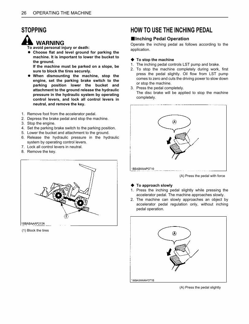
STOPPING
To avoid personal injury or death:A Choose flat and level ground for parking the
machine. It is important to lower the bucket tothe ground. If the machine must be parked on a slope, besure to block the tires securely.
A When dismounting the machine, stop theengine, set the parking brake switch to theparking position lower the bucket andattachment to the ground release the hydraulicpressure in the hydraulic system by operatingcontrol levers, and lock all control levers inneutral, and remove the key.
1. Remove foot from the accelerator pedal.2. Depress the brake pedal and stop the machine.3. Stop the engine.4. Set the parking brake switch to the parking position.5. Lower the bucket and attachment to the ground.6. Release the hydraulic pressure in the hydraulic
system by operating control levers.7. Lock all control levers in neutral.8. Remove the key.
HOW TO USE THE INCHING PEDALBInching Pedal OperationOperate the inching pedal as follows according to theapplication.
C To stop the machine1. The inching pedal controls LST pump and brake.2. To stop the machine completely during work, first
press the pedal slightly. Oil flow from LST pumpcomes to zero and cuts the driving power to slow downor stop the machine.
3. Press the pedal completely. The disc brake will be applied to stop the machinecompletely.
C To approach slowly1. Press the inching pedal slightly while pressing the
accelerator pedal. The machine approaches slowly.2. The machine can slowly approaches an object by
accelerator pedal regulation only, without inchingpedal operation.
(1) Block the tires
(A) Press the pedal with force
(A) Press the pedal slightly
27OPERATING THE MACHINE
C To scoop during diggingIn case of the bucket does not raise up during digging,press the inching pedal.Traction force is reduced and lifting force is increased, ifthe inching pedal is pressed.
BUse the Inching Pedal According to the Job.
To avoid personal injury or death:A When traveling with a fully-loaded bucket, do
not press the inching pedal all the way. Themachine will brake abruptly and causedangerous loss of balance that may cause anaccident.
C Loading1. Press the inching pedal slightly while pressing the
accelerator pedal to approach an object slowly. Slow approach can be done also by regulatingaccelerator pedal operation.
2. The bucket can be operated at the maximum enginerpm when the inching pedal is used to approachslowly. Bucket operation speed is thus maintained.
3. Press the inching pedal slightly to allow the machine toapproach to the desired stop position. Then press the pedal all the way to stop the machinecompletely.
(A) Press the pedal fully(B) Release the pedal
(A) Press the pedal slightly
OPERATING THE MACHINE28
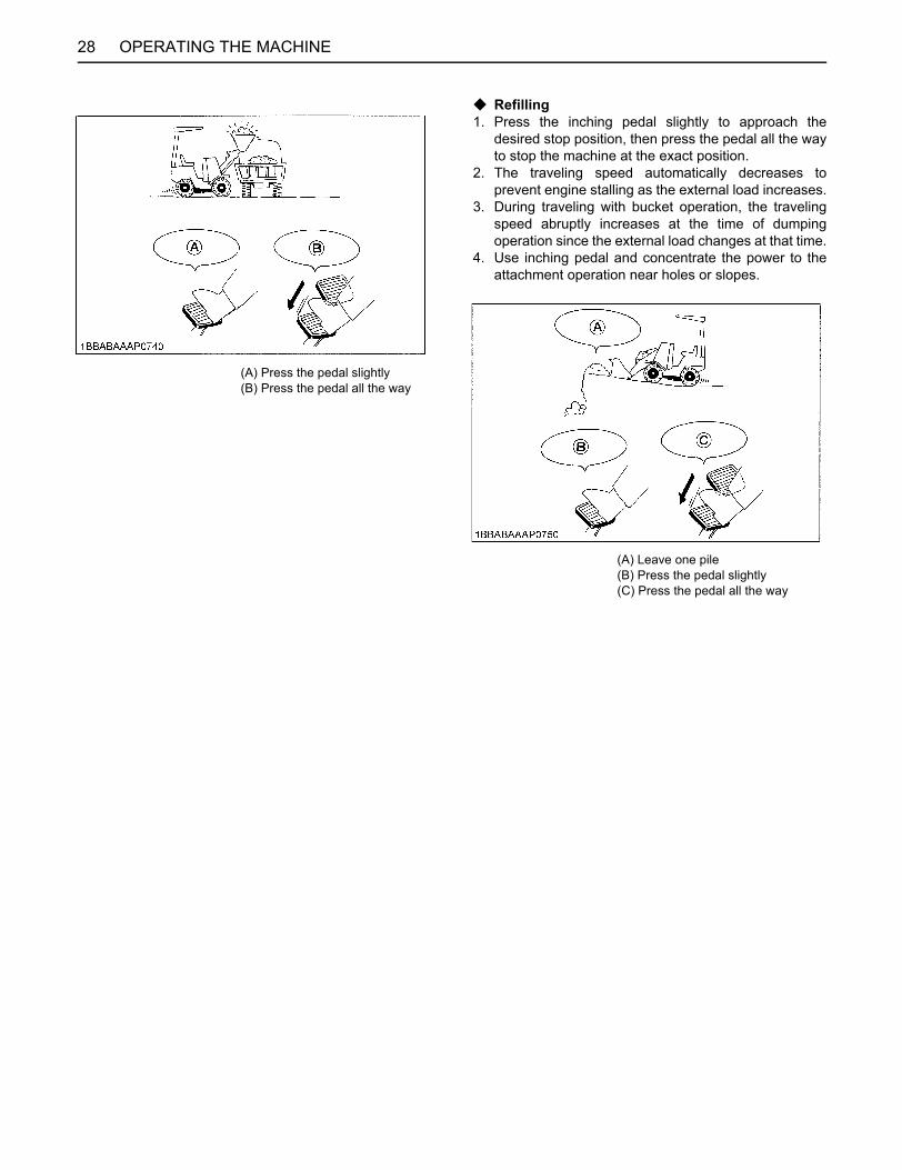
C Refilling1. Press the inching pedal slightly to approach the
desired stop position, then press the pedal all the wayto stop the machine at the exact position.
2. The traveling speed automatically decreases toprevent engine stalling as the external load increases.
3. During traveling with bucket operation, the travelingspeed abruptly increases at the time of dumpingoperation since the external load changes at that time.
4. Use inching pedal and concentrate the power to theattachment operation near holes or slopes.
(A) Press the pedal slightly(B) Press the pedal all the way
(A) Leave one pile(B) Press the pedal slightly(C) Press the pedal all the way
29OPERATING THE MACHINE
TYPICAL JOBS USING A WHEEL LOADERBelow are some typical jobs performed using a wheelloader. The machine can also be used to perform otherjobs by connection with various attachments.
To avoid personal injury or death:A When transporting a load, keep the loader
bucket as low as possible to avoid tipping over. Be extremely careful when working on inclines.
A Unreasonable operation such as on dangerousterrain, beyond the load capacity or beyond theintended use of the machine must be avoidedas it may cause the machine to tip over.
A Slow down before entering ungraded terrain.A Do not drive the machine close to the edges of
ditches or banks which may collapse under theweight of the machine especially when theground is loose or wet.
A Operating on slopes can be dangerous, rain,snow, loose gravel, soft ground, etc., willchange the ground conditions. Do not operate this machine in questionableground conditions.
A Never perform digging or shoveling with themachine in the articulated condition.
A Never dig or shovel at high speed. Such operation can cause the machine to losebalance and its rear wheels to lift off theground, which may in turn cause a seriousaccident.
A To avoid possible machine tip over, do notoperate the machine in any site whose terraincannot be ascertained, such as groundcovered with seeds or snow and check forhidden projections, dents, road shoulders, etc.,beforehand, and take care not to approachthem during work.
A Be sure to ease up on the accelerator at the endof backfilling grooves, or areas at the edge ofcliffs or pond banks, or at the end of an ascent:Upon removal of the external load, the machinespeed will automatically increase, reducespeed to avoid entering grooves or tippingover.
A To avoid machine slip or tipping over, do notoperate the machine on ungraded or softterrain, such as landfills. Grade and compactthe site beforehand at all times.
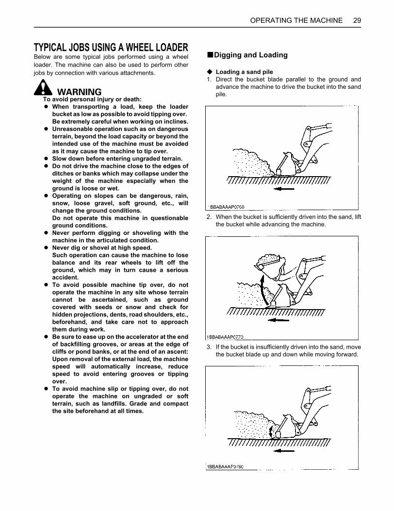
BDigging and Loading
C Loading a sand pile1. Direct the bucket blade parallel to the ground and
advance the machine to drive the bucket into the sandpile.
2. When the bucket is sufficiently driven into the sand, liftthe bucket while advancing the machine.
3. If the bucket is insufficiently driven into the sand, movethe bucket blade up and down while moving forward.
OPERATING THE MACHINE30
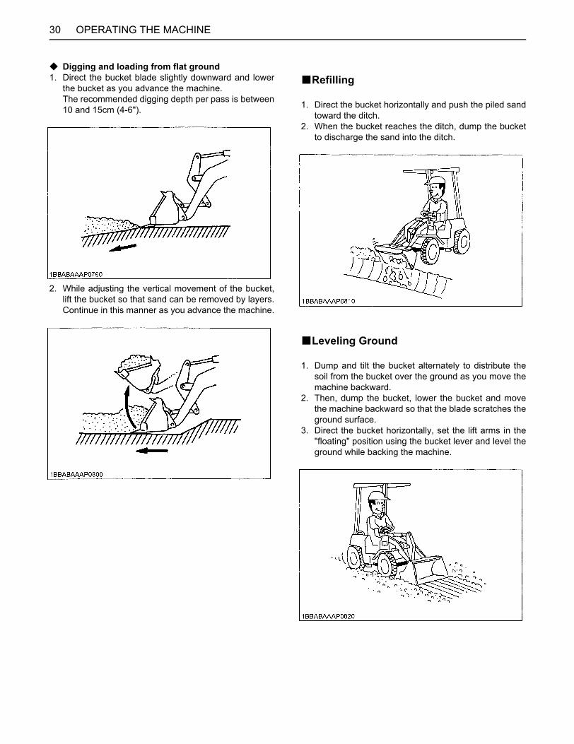
C Digging and loading from flat ground1. Direct the bucket blade slightly downward and lower
the bucket as you advance the machine. The recommended digging depth per pass is between10 and 15cm (4-6").
2. While adjusting the vertical movement of the bucket,lift the bucket so that sand can be removed by layers.Continue in this manner as you advance the machine.
BRefilling
1. Direct the bucket horizontally and push the piled sandtoward the ditch.
2. When the bucket reaches the ditch, dump the bucketto discharge the sand into the ditch.
BLeveling Ground
1. Dump and tilt the bucket alternately to distribute thesoil from the bucket over the ground as you move themachine backward.
2. Then, dump the bucket, lower the bucket and movethe machine backward so that the blade scratches theground surface.
3. Direct the bucket horizontally, set the lift arms in the"floating" position using the bucket lever and level theground while backing the machine.
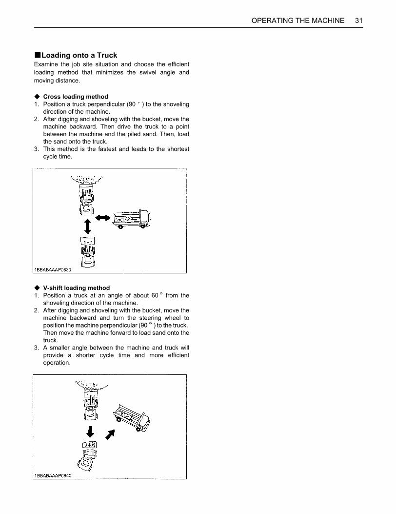
31OPERATING THE MACHINE
BLoading onto a TruckExamine the job site situation and choose the efficientloading method that minimizes the swivel angle andmoving distance.
C Cross loading method1. Position a truck perpendicular (90 ) to the shoveling
direction of the machine.2. After digging and shoveling with the bucket, move the
machine backward. Then drive the truck to a pointbetween the machine and the piled sand. Then, loadthe sand onto the truck.
3. This method is the fastest and leads to the shortestcycle time.
C V-shift loading method1. Position a truck at an angle of about 60 from the
shoveling direction of the machine.2. After digging and shoveling with the bucket, move the
machine backward and turn the steering wheel toposition the machine perpendicular (90 ) to the truck. Then move the machine forward to load sand onto thetruck.
3. A smaller angle between the machine and truck willprovide a shorter cycle time and more efficientoperation.
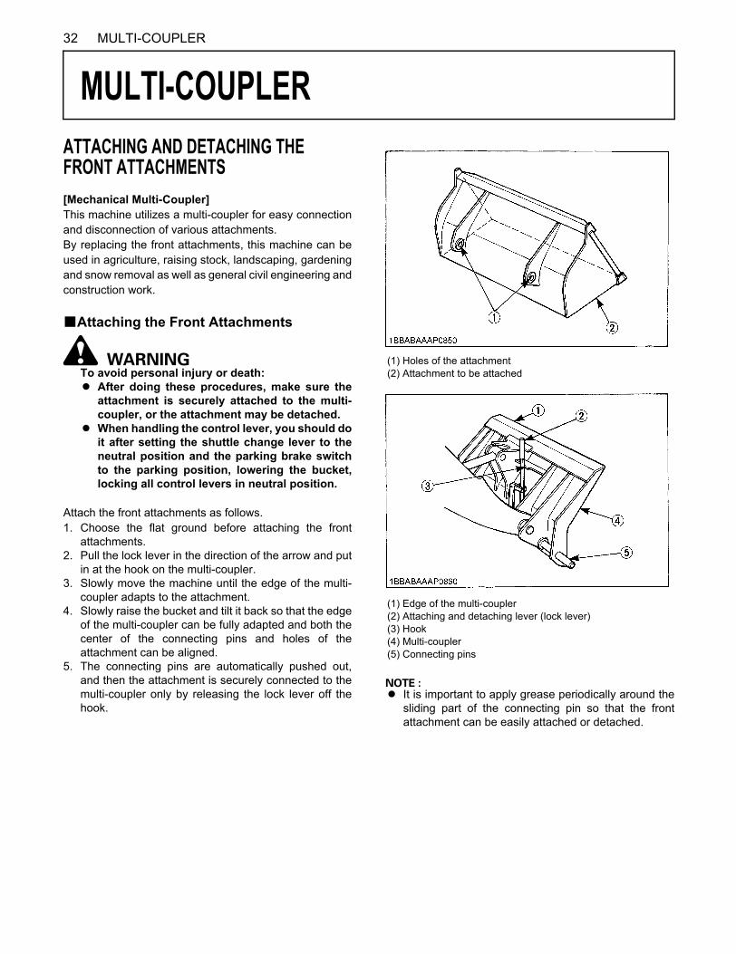
32 MULTI-COUPLER
MULTI-COUPLER
ATTACHING AND DETACHING THE FRONT ATTACHMENTS[Mechanical Multi-Coupler]This machine utilizes a multi-coupler for easy connectionand disconnection of various attachments.By replacing the front attachments, this machine can beused in agriculture, raising stock, landscaping, gardeningand snow removal as well as general civil engineering andconstruction work.BAttaching the Front Attachments
To avoid personal injury or death:A After doing these procedures, make sure the
attachment is securely attached to the multi-coupler, or the attachment may be detached.
A When handling the control lever, you should doit after setting the shuttle change lever to theneutral position and the parking brake switchto the parking position, lowering the bucket,locking all control levers in neutral position.
Attach the front attachments as follows.1. Choose the flat ground before attaching the front
attachments.2. Pull the lock lever in the direction of the arrow and put
in at the hook on the multi-coupler.3. Slowly move the machine until the edge of the multi-
coupler adapts to the attachment.4. Slowly raise the bucket and tilt it back so that the edge
of the multi-coupler can be fully adapted and both thecenter of the connecting pins and holes of theattachment can be aligned.
5. The connecting pins are automatically pushed out,and then the attachment is securely connected to themulti-coupler only by releasing the lock lever off thehook.
A It is important to apply grease periodically around thesliding part of the connecting pin so that the frontattachment can be easily attached or detached.
(1) Holes of the attachment(2) Attachment to be attached
(1) Edge of the multi-coupler(2) Attaching and detaching lever (lock lever)(3) Hook(4) Multi-coupler(5) Connecting pins
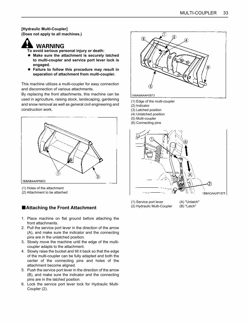
33MULTI-COUPLER
[Hydraulic Multi-Coupler](Does not apply to all machines.)
To avoid serious personal injury or death:A Make sure the attachment is securely latched
to multi-coupler and service port lever lock isengaged.
A Failure to follow this procedure may result inseparation of attachment from multi-coupler.
This machine utilizes a multi-coupler for easy connectionand disconnection of various attachments.By replacing the front attachments, this machine can beused in agriculture, raising stock, landscaping, gardeningand snow removal as well as general civil engineering andconstruction work.
BAttaching the Front Attachment
1. Place machine on flat ground before attaching thefront attachments.
2. Pull the service port lever in the direction of the arrow(A), and make sure the indicator and the connectingpins are in the unlatched position.
3. Slowly move the machine until the edge of the multi-coupler adapts to the attachment.
4. Slowly raise the bucket and tilt it back so that the edgeof the multi-coupler can be fully adapted and both thecenter of the connecting pins and holes of theattachment become aligned.
5. Push the service port lever in the direction of the arrow(B), and make sure the indicator and the connectingpins are in the latched position.
6. Lock the service port lever lock for Hydraulic Multi-Coupler (2).
(1) Holes of the attachment(2) Attachment to be attached
(1) Edge of the multi-coupler(2) Indicator(3) Latched position(4) Unlatched position(5) Multi-coupler(6) Connecting pins
(1) Service port lever(2) Hydraulic Multi-Coupler
(A) "Unlatch"(B) "Latch"
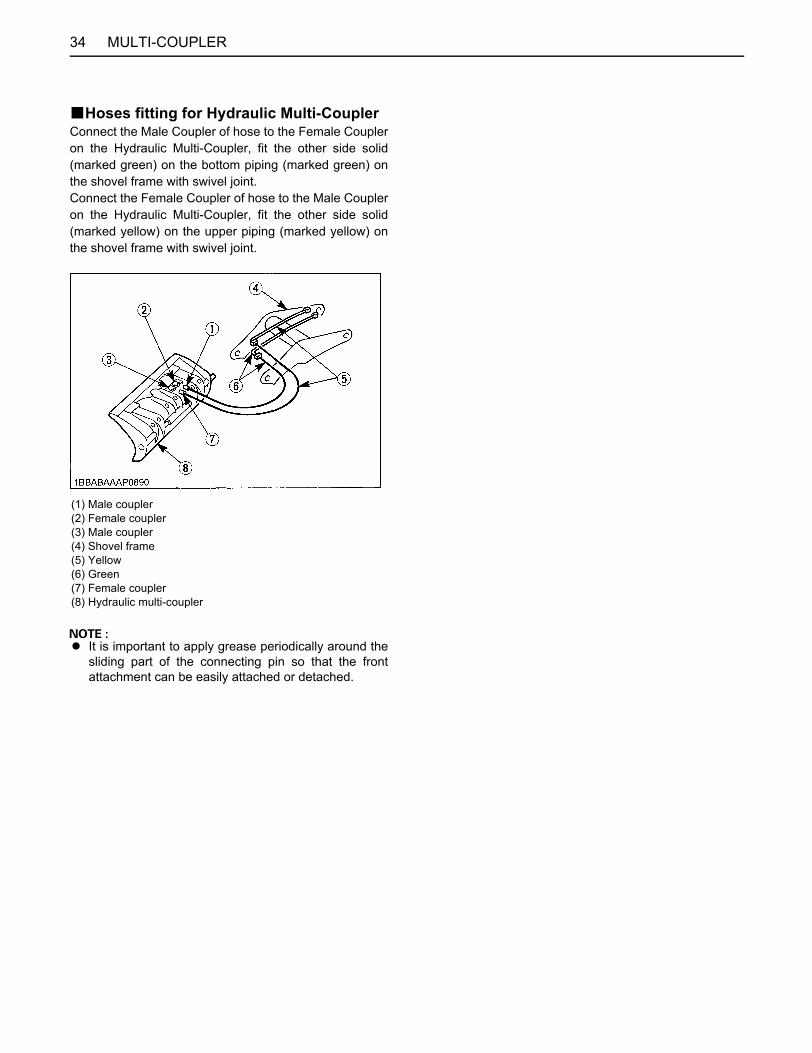
MULTI-COUPLER34
BHoses fitting for Hydraulic Multi-CouplerConnect the Male Coupler of hose to the Female Coupleron the Hydraulic Multi-Coupler, fit the other side solid(marked green) on the bottom piping (marked green) onthe shovel frame with swivel joint.Connect the Female Coupler of hose to the Male Coupleron the Hydraulic Multi-Coupler, fit the other side solid(marked yellow) on the upper piping (marked yellow) onthe shovel frame with swivel joint.
A It is important to apply grease periodically around thesliding part of the connecting pin so that the frontattachment can be easily attached or detached.
(1) Male coupler(2) Female coupler(3) Male coupler(4) Shovel frame(5) Yellow(6) Green(7) Female coupler(8) Hydraulic multi-coupler
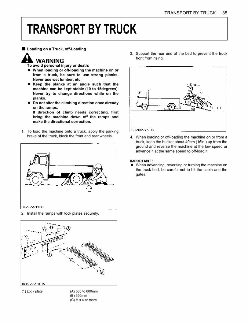
35TRANSPORT BY TRUCK
TRANSPORT BY TRUCK
B Loading on a Truck, off-LoadingTo avoid personal injury or death:A When loading or off-loading the machine on or
from a truck, be sure to use strong planks.Never use wet lumber, etc.
A Keep the planks at an angle such that themachine can be kept stable (10 to 15degrees).Never try to change directions while on theplanks.
A Do not alter the climbing direction once alreadyon the ramps. If direction of climb needs correcting, firstbring the machine down off the ramps andmake the directional correction.
1. To load the machine onto a truck, apply the parkingbrake of the truck, block the front and rear wheels.
2. Install the ramps with lock plates securely.
3. Support the rear end of the bed to prevent the truckfront from rising.
4. When loading or off-loading the machine on or from atruck, keep the bucket about 40cm (16in.) up from theground and reverse the machine at the low speed oradvance it at the same speed to off-load it.
A When advancing, reversing or turning the machine onthe truck bed, be careful not to hit the cabin and thegates.
(1) Lock plate (A) 500 to 600mm(B) 650mm(C) H x 4 or more

TRANSPORT BY TRUCK36
B Transportation
To avoid personal injury or death:A Before transportion, do the following to
prevent the machine from moving duringtransportation.
(1) Check to see that the machine's center pointaligns with that of the truck bed.
(2) Stop the engine.(3) Set the parking brake switch to the parking
position.(4) Lower the bucket and attachment to the truck
bed.(5) Release the hydraulic pressure in the
hydraulic system by operating control levers.(6) Lock all control levers in neutral.(7) Secure the steering frame lock and remove
the key.(8) Block the machine's wheels.(9) Securely fasten the machine to the truck.
After loading the machine, lower the bucket, outriggers onthe truck bed. Set the shuttle change lever to the neutralposition and the parking brake switch to the parkingposition. Securely fasten the machine to the truck ortrailer.
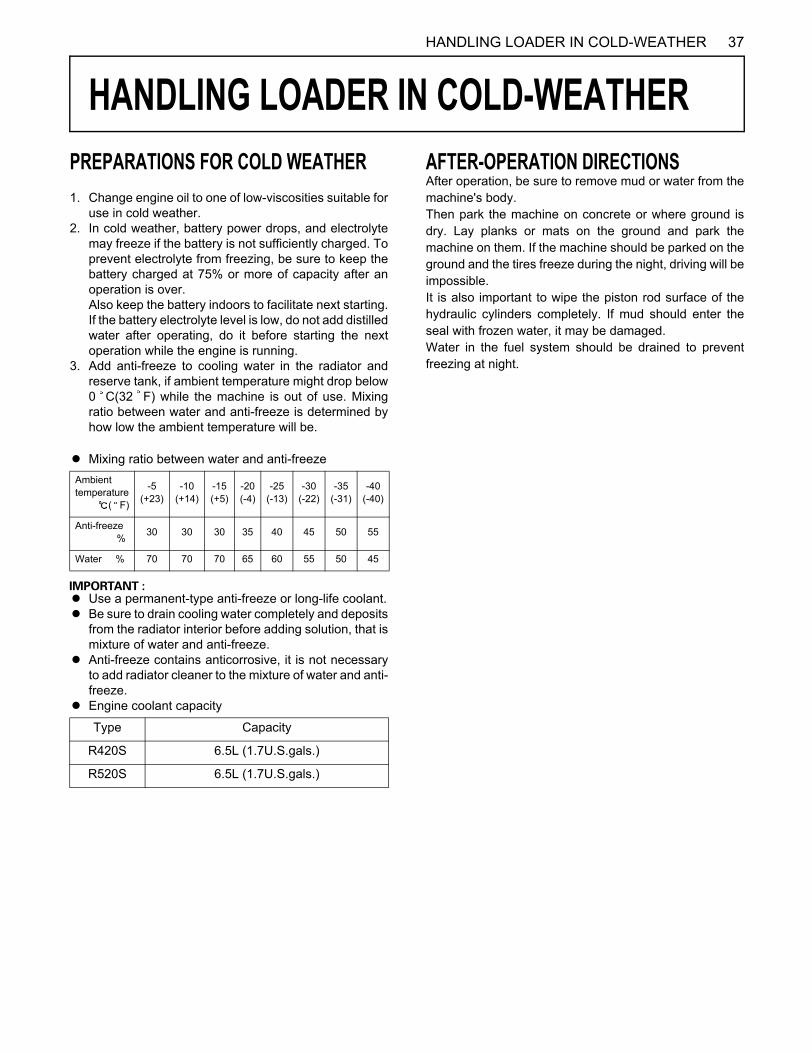
37HANDLING LOADER IN COLD-WEATHER
HANDLING LOADER IN COLD-WEATHER
PREPARATIONS FOR COLD WEATHER1. Change engine oil to one of low-viscosities suitable foruse in cold weather.2. In cold weather, battery power drops, and electrolyte
may freeze if the battery is not sufficiently charged. Toprevent electrolyte from freezing, be sure to keep thebattery charged at 75% or more of capacity after anoperation is over. Also keep the battery indoors to facilitate next starting.If the battery electrolyte level is low, do not add distilledwater after operating, do it before starting the nextoperation while the engine is running.
3. Add anti-freeze to cooling water in the radiator andreserve tank, if ambient temperature might drop below0 C(32 F) while the machine is out of use. Mixingratio between water and anti-freeze is determined byhow low the ambient temperature will be.
A Mixing ratio between water and anti-freeze
A Use a permanent-type anti-freeze or long-life coolant.A Be sure to drain cooling water completely and deposits
from the radiator interior before adding solution, that ismixture of water and anti-freeze.
A Anti-freeze contains anticorrosive, it is not necessaryto add radiator cleaner to the mixture of water and anti-freeze.
A Engine coolant capacity
AFTER-OPERATION DIRECTIONSAfter operation, be sure to remove mud or water from themachine's body.Then park the machine on concrete or where ground isdry. Lay planks or mats on the ground and park themachine on them. If the machine should be parked on theground and the tires freeze during the night, driving will beimpossible.It is also important to wipe the piston rod surface of thehydraulic cylinders completely. If mud should enter theseal with frozen water, it may be damaged.Water in the fuel system should be drained to preventfreezing at night.
Ambient temperature ( F)
-5 (+23)
-10 (+14)
-15 (+5)
-20 (-4)
-25 (-13)
-30 (-22)
-35 (-31)
-40 (-40)
Anti-freeze % 30 30 30 35 40 45 50 55
Water % 70 70 70 65 60 55 50 45
Type Capacity
R420S 6.5L (1.7U.S.gals.)
R520S 6.5L (1.7U.S.gals.)
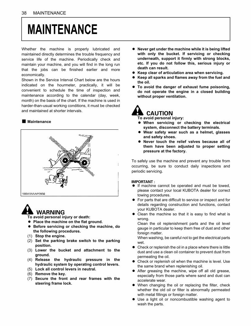
38 MAINTENANCE
MAINTENANCE
Whether the machine is properly lubricated andmaintained directly determines the trouble frequency andservice life of the machine. Periodically check andmaintain your machine, and you will find in the long runthat the jobs can be finished earlier and moreeconomically.Shown in the Service Interval Chart below are the hoursindicated on the hourmeter, practically, it will beconvenient to schedule the time of inspection andmaintenance according to the calendar (day, week,month) on the basis of the chart. If the machine is used inharder-than-usual working conditions, it must be checkedand maintained at shorter intervals.B Maintenance
To avoid personal injury or death:A Place the machine on the flat ground.A Before servicing or checking the machine, do
the following procedures.(1) Stop the engine.(2) Set the parking brake switch to the parking
position.(3) Lower the bucket and attachment to the
ground.(4) Release the hydraulic pressure in the
hydraulic system by operating control levers.(5) Lock all control levers in neutral.(6) Remove the key.(7) Secure the front and rear frames with the
steering frame lock.
A Never get under the machine while it is being liftedwith only the bucket. If servicing or checkingunderneath, support it firmly with strong blocks,etc. If you do not follow this, serious injury ordeath can result.
A Keep clear of articulation area when servicing.A Keep all sparks and flames away from the fuel and
the oil.A To avoid the danger of exhaust fume poisoning,
do not operate the engine in a closed buildingwithout proper ventilation.
To avoid personal injury:A When servicing or checking the electrical
system, disconnect the battery terminals.A Wear safety wear such as a helmet, glasses
and safety shoes.A Never touch the relief valves because all of
them have been adjusted to proper settingpressure at the factory.
To safely use the machine and prevent any trouble fromoccurring, be sure to conduct daily inspections andperiodic servicing.
A If machine cannot be operated and must be towed,please contact your local KUBOTA dealer for correcttowing procedures.
A For parts that are difficult to service or inspect and fordetails regarding construction and functions, contactyour KUBOTA dealer.
A Clean the machine so that it is easy to find what iswrong. Clean the oil replenishment parts and the oil levelgauge in particular to keep them free of dust and otherforeign matter. When washing, be careful not to get the electrical partswet.
A Check or replenish the oil in a place where there is littledust and use a clean oil container to prevent dust frompermeating the oil.
A Check or replenish oil when the machine is level. Usethe same brand when replenishing oil.
A After greasing the machine, wipe off all old grease,especially from those parts where sand and dust canaccelerate wear.
A When changing the oil or replacing the filter, checkwhether the old oil or filter is abnormally permeatedwith metal fillings or foreign matter.
A Use a light oil or noncombustible washing agent towash the parts.
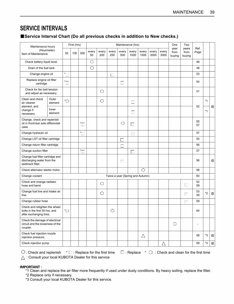
39MAINTENANCE
SERVICE INTERVALSBService Interval Chart (Do all previous checks in addition to New checks.)
: Check and replenish * : Replace for the first time : Replace * : Check and clean for the first time: Consult your local KUBOTA Dealer for this service
*1 Clean and replace the air filter more frequently if used under dusty conditions. By heavy soiling, replace the filter.*2 Replace only if necessary.*3 Consult your local KUBOTA Dealer for this service.
Maintenance hours (Hourmeter) Item of Maintenance
First (hrs) Maintenance (hrs) One year from
buying
Two years from
buying
Ref. Page50 100 500 every
50every 200
every 250
every 500
every 1000
every 1500
every 2000
every 3000
Check battery liquid level. 49
Drain of the fuel tank 48
Change engine oil * 53
Replace engine oil filter cartridge * 54
Check for fan belt tension and adjust as necessary. 51
Clean and check air cleaner element, and change if necessary.
Outer element *
52
*1
@Inner element *1
Change, check and replenish oil in front/rear axle differential case.
* 55 57
Change hydraulic oil. * 57
Change LST oil filter cartridge 55
Change return filter cartridge 56
Change suction filter * 57
Change fuel filter cartridge and discharging water from the sediment filter.
56 @
Check alternator starter motor. 58
Change coolant Twice a year (Spring and Autumn) 60
Check and change radiator hose and band.
52 59
Change fuel line and intake air line.
53 59 *2 @
Change rubber hose 59
Check and retighten the wheel bolts in the first 50 hrs, and after exchanging tires.
* 64
Check the damage of electrical circuit and the looseness of the coupler.
-
Check fuel injection nozzle injection pressure. 58 *3 @
Check injection pump 59 *3 @

40 MAINTENANCE
A The items listed above (@ marked) are registered as emission related critical parts by KUBOTA in the U.S.EPA nonroademission regulation. As the engine owner, you are responsible for the performance of the required maintenance on theengine according to the above instruction. Please see the Warranty Statement in detail.
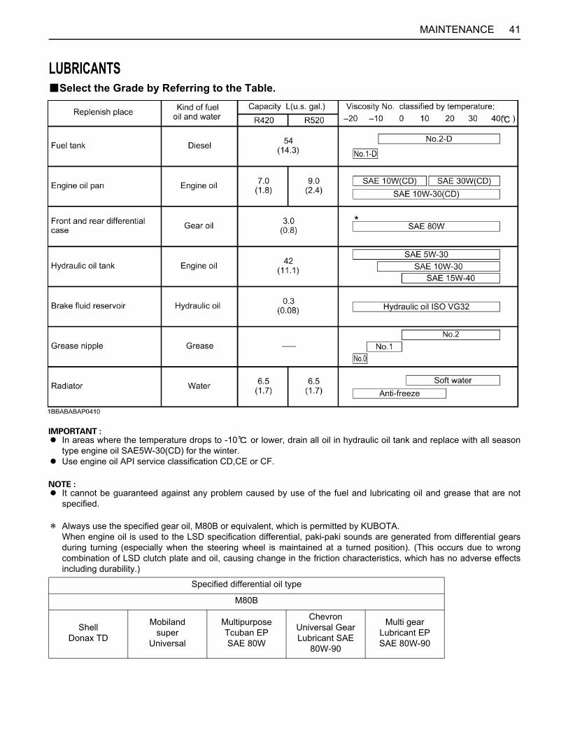
41MAINTENANCE
LUBRICANTSBSelect the Grade by Referring to the Table.
A In areas where the temperature drops to -10 or lower, drain all oil in hydraulic oil tank and replace with all seasontype engine oil SAE5W-30(CD) for the winter.
A Use engine oil API service classification CD,CE or CF.
A It cannot be guaranteed against any problem caused by use of the fuel and lubricating oil and grease that are notspecified.
D Always use the specified gear oil, M80B or equivalent, which is permitted by KUBOTA. When engine oil is used to the LSD specification differential, paki-paki sounds are generated from differential gearsduring turning (especially when the steering wheel is maintained at a turned position). (This occurs due to wrongcombination of LSD clutch plate and oil, causing change in the friction characteristics, which has no adverse effectsincluding durability.)
Specified differential oil type
M80B
Shell Donax TD
Mobiland super
Universal
Multipurpose Tcuban EP SAE 80W
Chevron Universal Gear Lubricant SAE
80W-90
Multi gear Lubricant EP SAE 80W-90
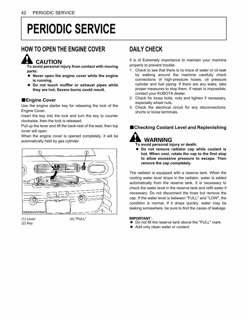
42 PERIODIC SERVICE
PERIODIC SERVICE
HOW TO OPEN THE ENGINE COVERTo avoid personal injury from contact with movingparts:A Never open the engine cover while the engine
is running.A Do not touch muffler or exhaust pipes while
they are hot; Severe burns could result.
BEngine CoverUse the engine starter key for releasing the lock of theEngine Cover.Insert the key into the lock and turn the key to counterclockwise, then the lock is released.Pull up the lever and lift the back-rest of the seat, then topcover will open.When the engine cover is opened completely, it will beautomatically held by gas cylinder.
DAILY CHECKIt is of Extremely importance to maintain your machineproperly to prevent trouble.1. Check to see that there is no trace of water or oil leak
by walking around the machine carefully checkconnections of high-pressure hoses, oil pressurecylinder and fuel piping. If there are any leaks, takeproper measures to stop them. If repair is impossible,contact your KUBOTA dealer.
2. Check for loose bolts, nuts and tighten if necessary,especially wheel nuts.
3. Check the electrical circuit for any disconnections,shorts or loose terminals.
BChecking Coolant Level and Replenishing
To avoid personal injury or death:A Do not remove radiator cap while coolant is
hot. When cool, rotate the cap to the first stopto allow excessive pressure to escape. Thenremove the cap completely.
The radiator is equipped with a reserve tank. When thecooling water level drops in the radiator, water is addedautomatically from the reserve tank. It is necessary tocheck the water level in the reserve tank and refill water ifnecessary. Do not disconnect the hose but remove thecap. If the water level is between "FULL" and "LOW", thecondition is normal. If it drops quickly, water may beleaking somewhere, be sure to find the cause of leakage.
A Do not fill the reserve tank above the "FULL" mark.A Add only clean water or coolant.
(1) Lever(2) Key
(A) "PULL"
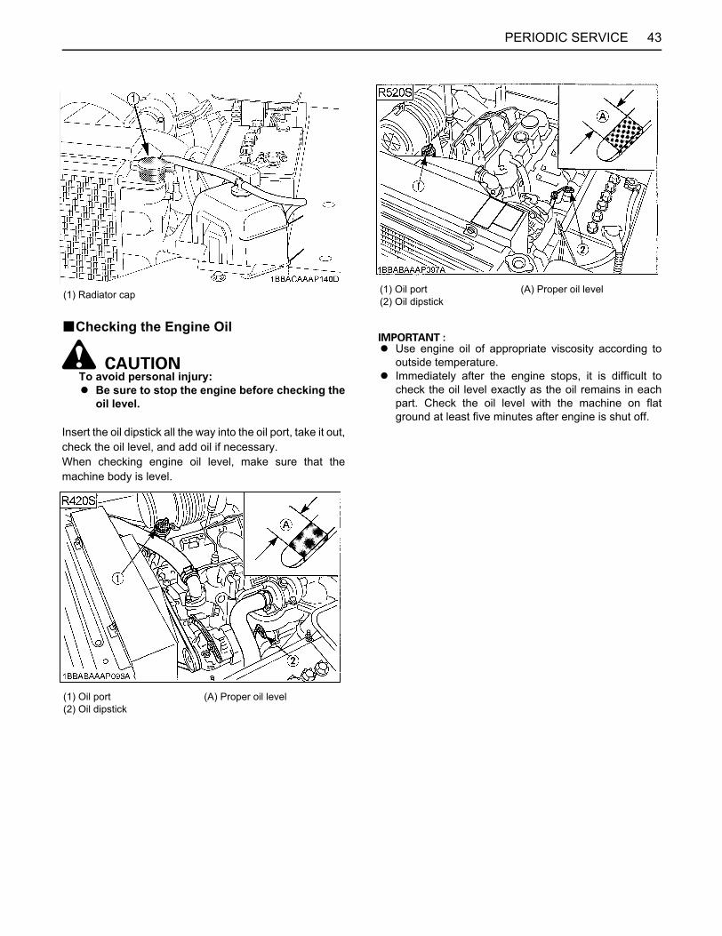
43PERIODIC SERVICE
BChecking the Engine Oil
To avoid personal injury:A Be sure to stop the engine before checking the
oil level.
Insert the oil dipstick all the way into the oil port, take it out,check the oil level, and add oil if necessary.When checking engine oil level, make sure that themachine body is level.
A Use engine oil of appropriate viscosity according tooutside temperature.
A Immediately after the engine stops, it is difficult tocheck the oil level exactly as the oil remains in eachpart. Check the oil level with the machine on flatground at least five minutes after engine is shut off.
(1) Radiator cap
(1) Oil port(2) Oil dipstick
(A) Proper oil level
(1) Oil port(2) Oil dipstick
(A) Proper oil level
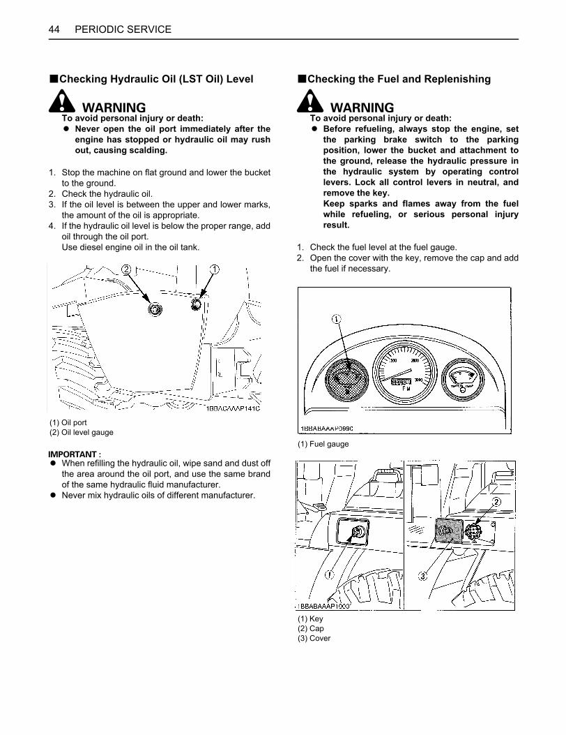
PERIODIC SERVICE44
BChecking Hydraulic Oil (LST Oil) Level
To avoid personal injury or death:A Never open the oil port immediately after the
engine has stopped or hydraulic oil may rushout, causing scalding.
1. Stop the machine on flat ground and lower the bucketto the ground.
2. Check the hydraulic oil.3. If the oil level is between the upper and lower marks,
the amount of the oil is appropriate.4. If the hydraulic oil level is below the proper range, add
oil through the oil port. Use diesel engine oil in the oil tank.
A When refilling the hydraulic oil, wipe sand and dust offthe area around the oil port, and use the same brandof the same hydraulic fluid manufacturer.
A Never mix hydraulic oils of different manufacturer.
BChecking the Fuel and Replenishing
To avoid personal injury or death:A Before refueling, always stop the engine, set
the parking brake switch to the parkingposition, lower the bucket and attachment tothe ground, release the hydraulic pressure inthe hydraulic system by operating controllevers. Lock all control levers in neutral, andremove the key.Keep sparks and flames away from the fuelwhile refueling, or serious personal injuryresult.
1. Check the fuel level at the fuel gauge.2. Open the cover with the key, remove the cap and add
the fuel if necessary.
(1) Oil port(2) Oil level gauge
(1) Fuel gauge
(1) Key(2) Cap(3) Cover
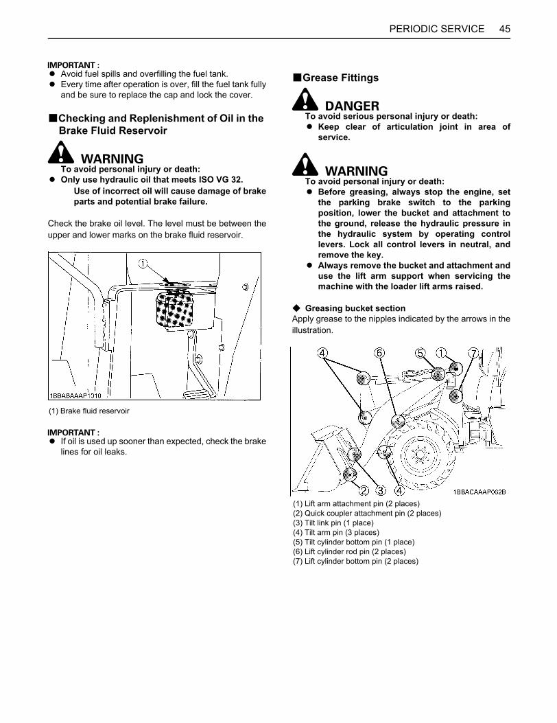
45PERIODIC SERVICE
A Avoid fuel spills and overfilling the fuel tank.A Every time after operation is over, fill the fuel tank fully
and be sure to replace the cap and lock the cover.
BChecking and Replenishment of Oil in the Brake Fluid Reservoir
To avoid personal injury or death:A Only use hydraulic oil that meets ISO VG 32.
Use of incorrect oil will cause damage of brakeparts and potential brake failure.
Check the brake oil level. The level must be between theupper and lower marks on the brake fluid reservoir.
A If oil is used up sooner than expected, check the brakelines for oil leaks.
BGrease Fittings
To avoid serious personal injury or death:A Keep clear of articulation joint in area of
service.
To avoid personal injury or death:A Before greasing, always stop the engine, set
the parking brake switch to the parkingposition, lower the bucket and attachment tothe ground, release the hydraulic pressure inthe hydraulic system by operating controllevers. Lock all control levers in neutral, andremove the key.
A Always remove the bucket and attachment anduse the lift arm support when servicing themachine with the loader lift arms raised.
C Greasing bucket sectionApply grease to the nipples indicated by the arrows in theillustration.
(1) Brake fluid reservoir
(1) Lift arm attachment pin (2 places)(2) Quick coupler attachment pin (2 places)(3) Tilt link pin (1 place)(4) Tilt arm pin (3 places)(5) Tilt cylinder bottom pin (1 place)(6) Lift cylinder rod pin (2 places)(7) Lift cylinder bottom pin (2 places)
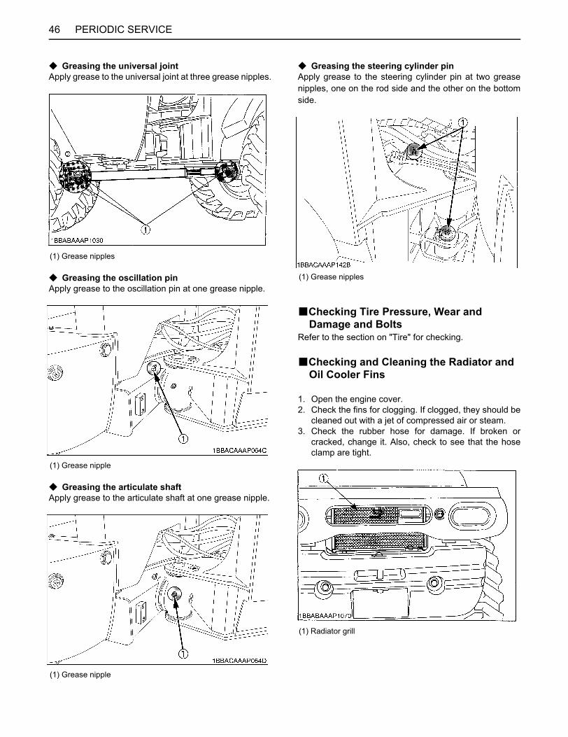
PERIODIC SERVICE46
C Greasing the universal jointApply grease to the universal joint at three grease nipples.
C Greasing the oscillation pinApply grease to the oscillation pin at one grease nipple.
C Greasing the articulate shaftApply grease to the articulate shaft at one grease nipple.
C Greasing the steering cylinder pinApply grease to the steering cylinder pin at two greasenipples, one on the rod side and the other on the bottomside.
BChecking Tire Pressure, Wear and Damage and Bolts
Refer to the section on "Tire" for checking.
BChecking and Cleaning the Radiator and Oil Cooler Fins
1. Open the engine cover.2. Check the fins for clogging. If clogged, they should be
cleaned out with a jet of compressed air or steam.3. Check the rubber hose for damage. If broken or
cracked, change it. Also, check to see that the hoseclamp are tight.
(1) Grease nipples
(1) Grease nipple
(1) Grease nipple
(1) Grease nipples
(1) Radiator grill

47PERIODIC SERVICE
BChecking the Parking Brake
1. Set the parking brake switch to the parking position totest its performance.
2. If it fails to work effectively, it must be adjusted by yourKUBOTA dealer.
BChecking the Brake Pedal
1. Check the brake pedal.2. If it fails to work effectively, it must be adjusted by your
KUBOTA dealer.
BChecking the Steering Wheel
1. Start the engine, turn the steering wheel left and rightand check the operation.
2. If any abnormality is found, have it inspected further byyour KUBOTA dealer.
BChecking and Tighten Loose Bolts and Nuts
Check the bolts and nuts and tighten them if necessary.
BChecking Electrical Wiring for Short-circuits and Loose Terminals
To avoid personal injury:A Never wear metal rings or metal watch bands.
You can make a ground for the electric circuitand get a burn on your hand or arm.
A Know the electrical circuit before you connector disconnect an electrical component. Awrong connection can cause injury or damage.
Check them carefully, since any defects will cause electricproblems.
BChecking the SMV Emblem for Stains and Damage
Check the SMV emblem for damage and stains, andreplace if necessary.
BChecking the Lamps and Meters
1. Check that the lamps flicker normally.2. Check that the meters work normally.
BTesting the HornCheck the horn's sound and operation.
BChecking Oil and Water LeakVisually check the machine's body.
(1) Parking brake switch
(1) Brake pedal
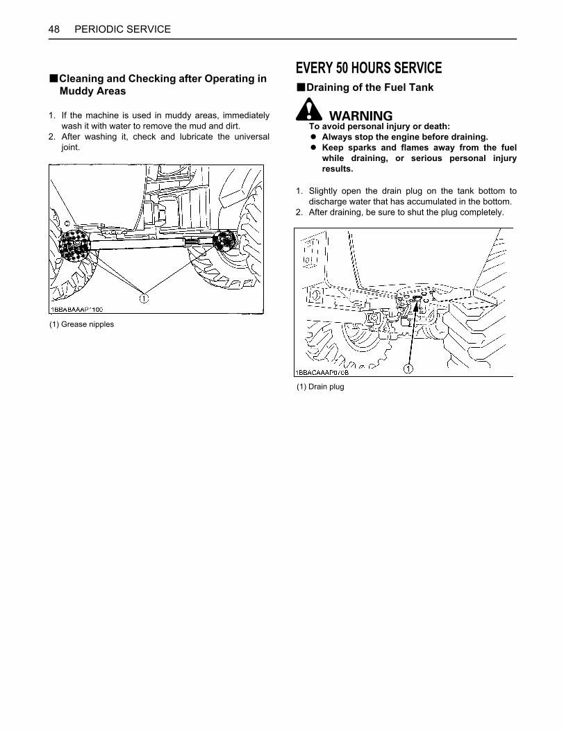
PERIODIC SERVICE48
BCleaning and Checking after Operating in Muddy Areas
1. If the machine is used in muddy areas, immediatelywash it with water to remove the mud and dirt.
2. After washing it, check and lubricate the universaljoint.
EVERY 50 HOURS SERVICEBDraining of the Fuel Tank
To avoid personal injury or death:A Always stop the engine before draining.A Keep sparks and flames away from the fuel
while draining, or serious personal injuryresults.
1. Slightly open the drain plug on the tank bottom todischarge water that has accumulated in the bottom.
2. After draining, be sure to shut the plug completely.
(1) Grease nipples
(1) Drain plug
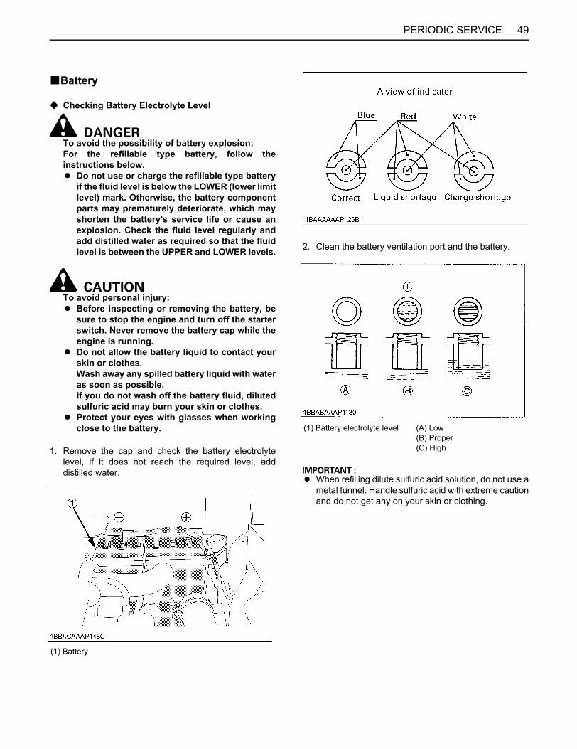
49PERIODIC SERVICE
BBattery
C Checking Battery Electrolyte Level
To avoid the possibility of battery explosion:For the refillable type battery, follow theinstructions below.A Do not use or charge the refillable type battery
if the fluid level is below the LOWER (lower limitlevel) mark. Otherwise, the battery componentparts may prematurely deteriorate, which mayshorten the battery's service life or cause anexplosion. Check the fluid level regularly andadd distilled water as required so that the fluidlevel is between the UPPER and LOWER levels.
To avoid personal injury:A Before inspecting or removing the battery, be
sure to stop the engine and turn off the starterswitch. Never remove the battery cap while theengine is running.
A Do not allow the battery liquid to contact yourskin or clothes. Wash away any spilled battery liquid with wateras soon as possible. If you do not wash off the battery fluid, dilutedsulfuric acid may burn your skin or clothes.
A Protect your eyes with glasses when workingclose to the battery.
1. Remove the cap and check the battery electrolytelevel, if it does not reach the required level, adddistilled water.
2. Clean the battery ventilation port and the battery.
A When refilling dilute sulfuric acid solution, do not use ametal funnel. Handle sulfuric acid with extreme cautionand do not get any on your skin or clothing.
(1) Battery
(1) Battery electrolyte level (A) Low(B) Proper(C) High
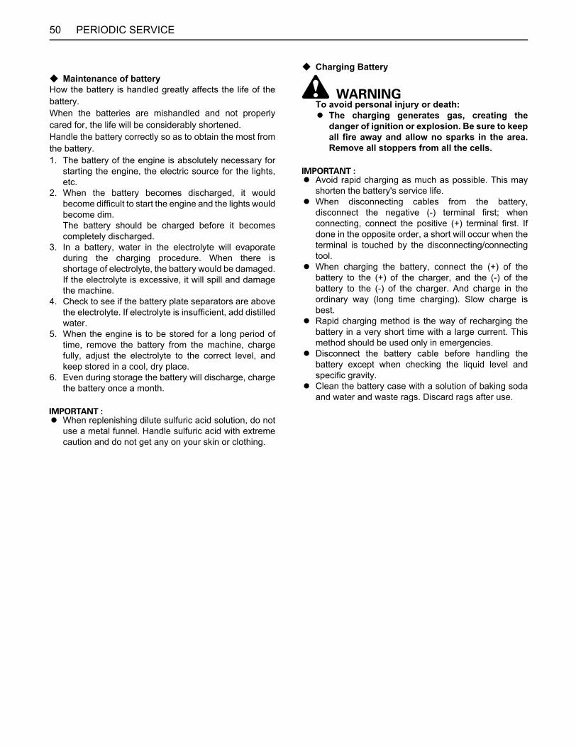
PERIODIC SERVICE50
C Maintenance of batteryHow the battery is handled greatly affects the life of thebattery.When the batteries are mishandled and not properlycared for, the life will be considerably shortened.Handle the battery correctly so as to obtain the most fromthe battery.1. The battery of the engine is absolutely necessary for
starting the engine, the electric source for the lights,etc.
2. When the battery becomes discharged, it wouldbecome difficult to start the engine and the lights wouldbecome dim. The battery should be charged before it becomescompletely discharged.
3. In a battery, water in the electrolyte will evaporateduring the charging procedure. When there isshortage of electrolyte, the battery would be damaged.If the electrolyte is excessive, it will spill and damagethe machine.
4. Check to see if the battery plate separators are abovethe electrolyte. If electrolyte is insufficient, add distilledwater.
5. When the engine is to be stored for a long period oftime, remove the battery from the machine, chargefully, adjust the electrolyte to the correct level, andkeep stored in a cool, dry place.
6. Even during storage the battery will discharge, chargethe battery once a month.
A When replenishing dilute sulfuric acid solution, do notuse a metal funnel. Handle sulfuric acid with extremecaution and do not get any on your skin or clothing.
C Charging Battery
To avoid personal injury or death:A The charging generates gas, creating the
danger of ignition or explosion. Be sure to keepall fire away and allow no sparks in the area.Remove all stoppers from all the cells.
A Avoid rapid charging as much as possible. This mayshorten the battery's service life.
A When disconnecting cables from the battery,disconnect the negative (-) terminal first; whenconnecting, connect the positive (+) terminal first. Ifdone in the opposite order, a short will occur when theterminal is touched by the disconnecting/connectingtool.
A When charging the battery, connect the (+) of thebattery to the (+) of the charger, and the (-) of thebattery to the (-) of the charger. And charge in theordinary way (long time charging). Slow charge isbest.
A Rapid charging method is the way of recharging thebattery in a very short time with a large current. Thismethod should be used only in emergencies.
A Disconnect the battery cable before handling thebattery except when checking the liquid level andspecific gravity.
A Clean the battery case with a solution of baking sodaand water and waste rags. Discard rags after use.
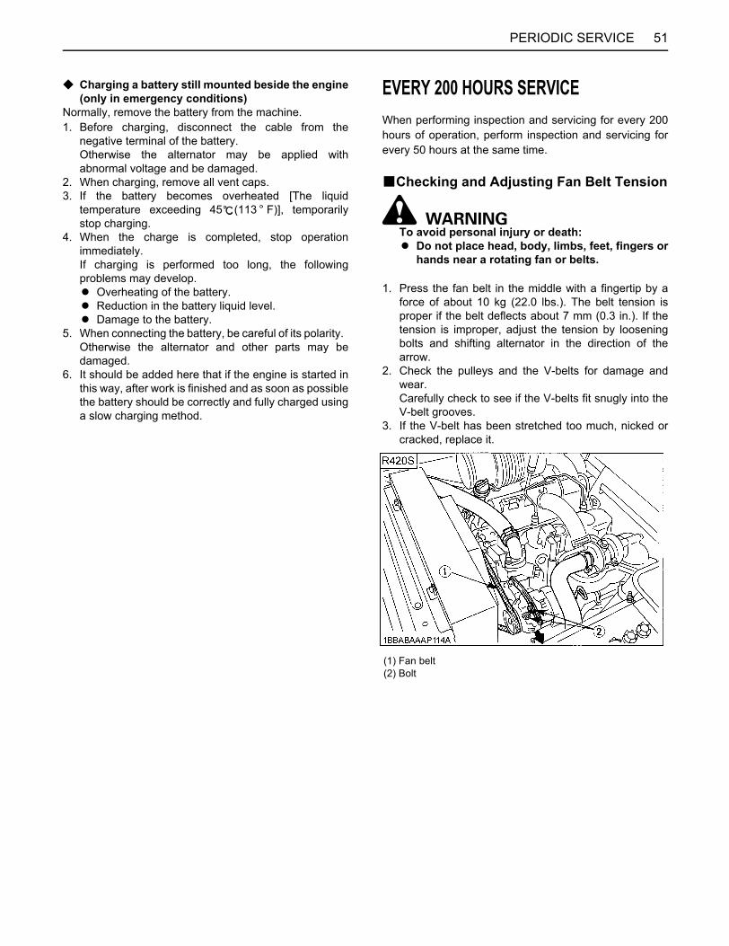
51PERIODIC SERVICE
C Charging a battery still mounted beside the engine(only in emergency conditions)
Normally, remove the battery from the machine.1. Before charging, disconnect the cable from the
negative terminal of the battery. Otherwise the alternator may be applied withabnormal voltage and be damaged.
2. When charging, remove all vent caps.3. If the battery becomes overheated [The liquid
temperature exceeding 45 (113 F)], temporarilystop charging.
4. When the charge is completed, stop operationimmediately. If charging is performed too long, the followingproblems may develop.A Overheating of the battery.A Reduction in the battery liquid level.A Damage to the battery.
5. When connecting the battery, be careful of its polarity. Otherwise the alternator and other parts may bedamaged.
6. It should be added here that if the engine is started inthis way, after work is finished and as soon as possiblethe battery should be correctly and fully charged usinga slow charging method.
EVERY 200 HOURS SERVICEWhen performing inspection and servicing for every 200hours of operation, perform inspection and servicing forevery 50 hours at the same time.
BChecking and Adjusting Fan Belt Tension
To avoid personal injury or death:A Do not place head, body, limbs, feet, fingers or
hands near a rotating fan or belts.
1. Press the fan belt in the middle with a fingertip by aforce of about 10 kg (22.0 lbs.). The belt tension isproper if the belt deflects about 7 mm (0.3 in.). If thetension is improper, adjust the tension by looseningbolts and shifting alternator in the direction of thearrow.
2. Check the pulleys and the V-belts for damage andwear. Carefully check to see if the V-belts fit snugly into theV-belt grooves.
3. If the V-belt has been stretched too much, nicked orcracked, replace it.
(1) Fan belt(2) Bolt
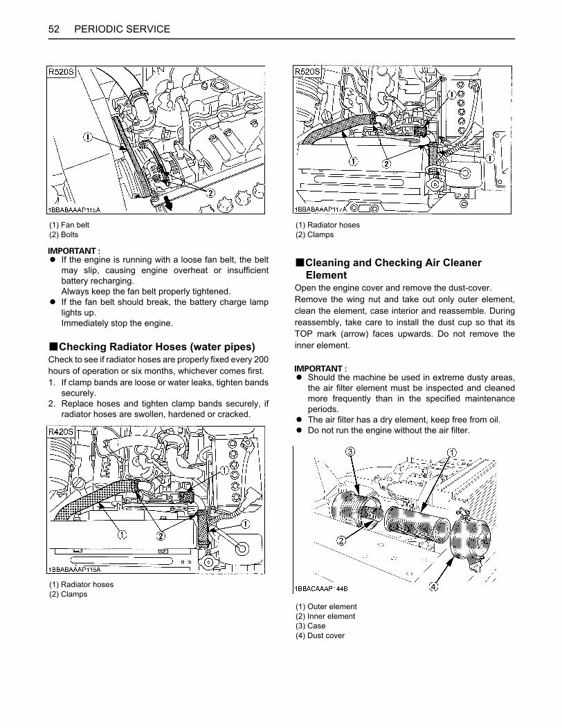
PERIODIC SERVICE52
A If the engine is running with a loose fan belt, the beltmay slip, causing engine overheat or insufficientbattery recharging. Always keep the fan belt properly tightened.
A If the fan belt should break, the battery charge lamplights up.Immediately stop the engine.
BChecking Radiator Hoses (water pipes)Check to see if radiator hoses are properly fixed every 200hours of operation or six months, whichever comes first.1. If clamp bands are loose or water leaks, tighten bands
securely.2. Replace hoses and tighten clamp bands securely, if
radiator hoses are swollen, hardened or cracked.
BCleaning and Checking Air Cleaner Element
Open the engine cover and remove the dust-cover.Remove the wing nut and take out only outer element,clean the element, case interior and reassemble. Duringreassembly, take care to install the dust cup so that itsTOP mark (arrow) faces upwards. Do not remove theinner element.
A Should the machine be used in extreme dusty areas,the air filter element must be inspected and cleanedmore frequently than in the specified maintenanceperiods.
A The air filter has a dry element, keep free from oil.A Do not run the engine without the air filter.
(1) Fan belt(2) Bolts
(1) Radiator hoses(2) Clamps
(1) Radiator hoses(2) Clamps
(1) Outer element(2) Inner element(3) Case(4) Dust cover

53PERIODIC SERVICE
BAir Filter Maintenance
To avoid personal injury:A Wear eye protection.
The quickest and safest method of maintenance is theexchange of the paper cartridge. Furthermore there aredifferent methods of cleaning the cartridge. C Cleaning with compressed airPressure of compressed air must be under 205kPa(2.1kgf/ ,30psi), and the cartridge should be blownclean from the inside to the outside until the dust depositsare remarkably reduced.
A If the air suction is still inadequate, or the color of theexhaust gases is abnormal even after the cleaning, theair filter cartridge must be replaced.
BChecking Fuel Line and Intake Air Line
1. Check to see that all lines and hose clamps are tightand not damaged.
2. If hoses and clamps are found worn or damaged,replace or repair them at once.
EVERY 250 HOURS SERVICEWhen performing inspection and servicing for every 250hours of operation, perform inspection and servicing forevery 50 hours at the same time.
BChanging Engine Oil (change it after first 50 hours of operation.)
To avoid personal injury or death:A Always stop the engine before changing the
engine oil.A Never open the drain plug immediately after the
engine has stopped, or hot engine oil may rushout, causing scalding.
1. Remove the drain plug on the bottom of the engine,and drain all the old oil. [The hexagon bolt: 22 mm]
2. Then retighten the plug completely.
3. Apply engine oil from the oil port to the correct level.4. Idle the engine. About 5 minutes after stopping the
engine, check with the oil level gauge to make sure theproper amount of engine oil has been supplied.
(1) Drain plug
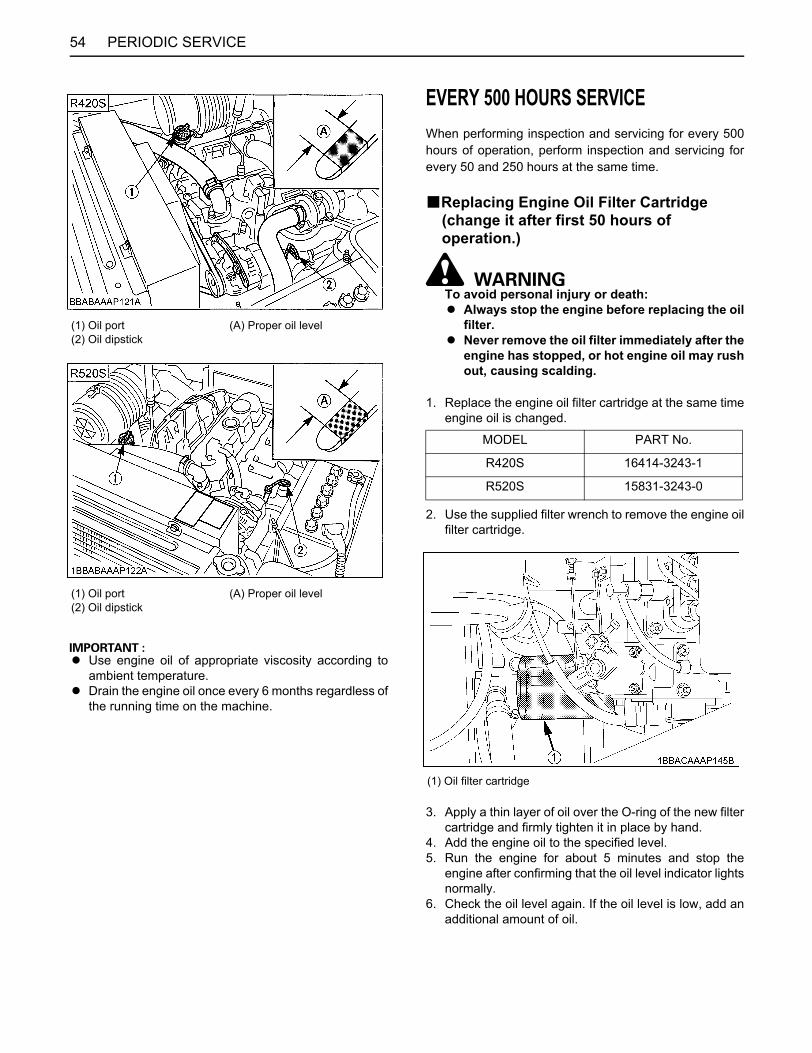
PERIODIC SERVICE54
A Use engine oil of appropriate viscosity according toambient temperature.
A Drain the engine oil once every 6 months regardless ofthe running time on the machine.
EVERY 500 HOURS SERVICEWhen performing inspection and servicing for every 500hours of operation, perform inspection and servicing forevery 50 and 250 hours at the same time.
BReplacing Engine Oil Filter Cartridge (change it after first 50 hours of operation.)
To avoid personal injury or death:A Always stop the engine before replacing the oil
filter.A Never remove the oil filter immediately after the
engine has stopped, or hot engine oil may rushout, causing scalding.
1. Replace the engine oil filter cartridge at the same timeengine oil is changed.
2. Use the supplied filter wrench to remove the engine oilfilter cartridge.
3. Apply a thin layer of oil over the O-ring of the new filtercartridge and firmly tighten it in place by hand.
4. Add the engine oil to the specified level.5. Run the engine for about 5 minutes and stop the
engine after confirming that the oil level indicator lightsnormally.
6. Check the oil level again. If the oil level is low, add anadditional amount of oil.
(1) Oil port(2) Oil dipstick
(A) Proper oil level
(1) Oil port(2) Oil dipstick
(A) Proper oil level
MODEL PART No.
R420S 16414-3243-1
R520S 15831-3243-0
(1) Oil filter cartridge
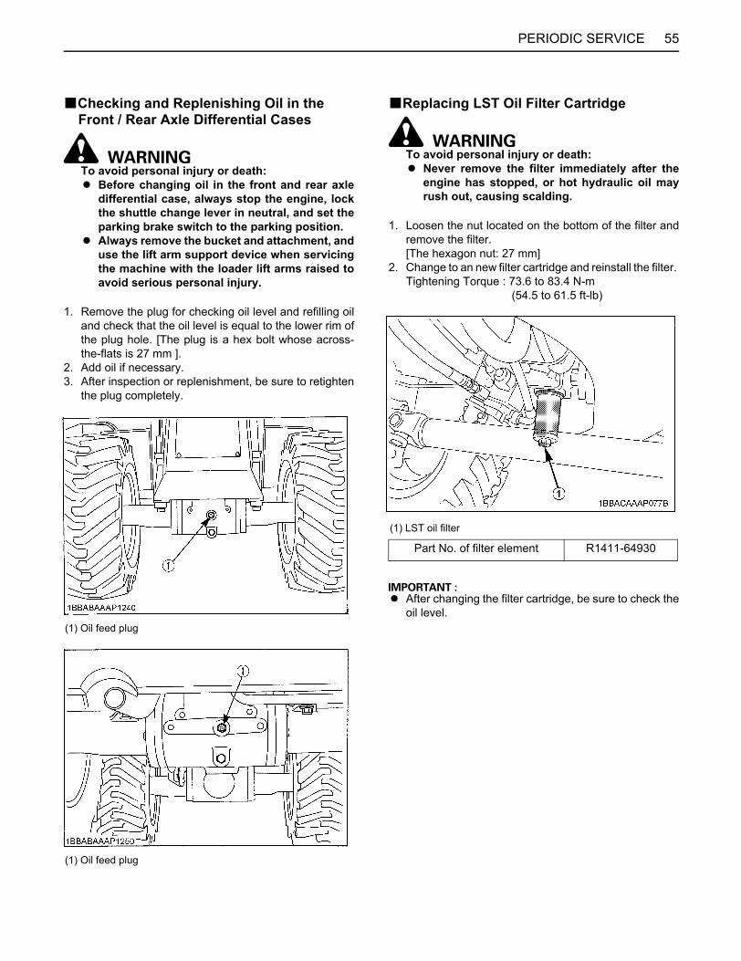
55PERIODIC SERVICE
BChecking and Replenishing Oil in the Front / Rear Axle Differential Cases
To avoid personal injury or death:A Before changing oil in the front and rear axle
differential case, always stop the engine, lockthe shuttle change lever in neutral, and set theparking brake switch to the parking position.
A Always remove the bucket and attachment, anduse the lift arm support device when servicingthe machine with the loader lift arms raised toavoid serious personal injury.
1. Remove the plug for checking oil level and refilling oiland check that the oil level is equal to the lower rim ofthe plug hole. [The plug is a hex bolt whose across-the-flats is 27 mm ].
2. Add oil if necessary.3. After inspection or replenishment, be sure to retighten
the plug completely.
BReplacing LST Oil Filter Cartridge
To avoid personal injury or death:A Never remove the filter immediately after the
engine has stopped, or hot hydraulic oil mayrush out, causing scalding.
1. Loosen the nut located on the bottom of the filter andremove the filter. [The hexagon nut: 27 mm]
2. Change to an new filter cartridge and reinstall the filter. Tightening Torque : 73.6 to 83.4 N-m (54.5 to 61.5 ft-lb)
A After changing the filter cartridge, be sure to check theoil level.
(1) Oil feed plug
(1) Oil feed plug
(1) LST oil filter
Part No. of filter element R1411-64930
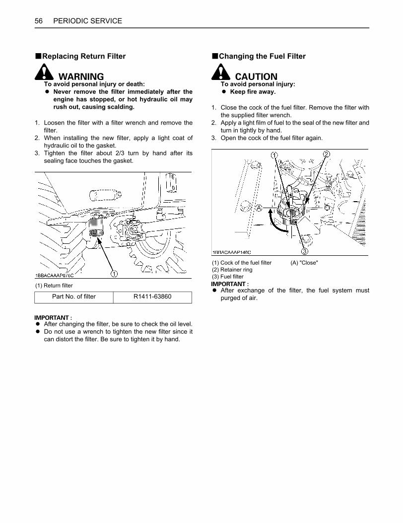
PERIODIC SERVICE56
BReplacing Return Filter
To avoid personal injury or death:A Never remove the filter immediately after the
engine has stopped, or hot hydraulic oil mayrush out, causing scalding.
1. Loosen the filter with a filter wrench and remove thefilter.
2. When installing the new filter, apply a light coat ofhydraulic oil to the gasket.
3. Tighten the filter about 2/3 turn by hand after itssealing face touches the gasket.
A After changing the filter, be sure to check the oil level.A Do not use a wrench to tighten the new filter since it
can distort the filter. Be sure to tighten it by hand.
BChanging the Fuel Filter
To avoid personal injury:A Keep fire away.
1. Close the cock of the fuel filter. Remove the filter withthe supplied filter wrench.
2. Apply a light film of fuel to the seal of the new filter andturn in tightly by hand.
3. Open the cock of the fuel filter again.
A After exchange of the filter, the fuel system mustpurged of air.
(1) Return filter
Part No. of filter R1411-63860
(1) Cock of the fuel filter (A) "Close"(2) Retainer ring(3) Fuel filter
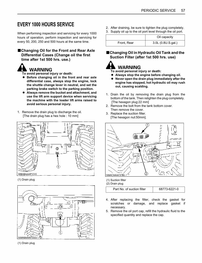
57PERIODIC SERVICE
EVERY 1000 HOURS SERVICEWhen performing inspection and servicing for every 1000hours of operation, perform inspection and servicing forevery 50, 200, 250 and 500 hours at the same time.
BChanging Oil for the Front and Rear Axle Differential Cases (Change oil the first time after 1st 500 hrs. use.)
To avoid personal injury or death:A Before changing oil in the front and rear axle
differential case, always stop the engine, lockthe shuttle change lever in neutral, and set theparking brake switch to the parking position.
A Always remove the bucket and attachment, anduse the lift arm support device when servicingthe machine with the loader lift arms raised toavoid serious personal injury.
1. Remove the drain plug to discharge the oil. [The drain plug has a hex hole : 10 mm]
2. After draining, be sure to tighten the plug completely.3. Supply oil up to the oil port level through the oil port.
BChanging Oil in Hydraulic Oil Tank and the Suction Filter (after 1st 500 hrs. use)
To avoid personal injury or death:A Always stop the engine before changing oil.A Never open the drain plug immediately after the
engine has stopped, hot hydraulic oil may rushout, causing scalding.
1. Drain the oil by removing the drain plug from thebottom of the tank. Then retighten the plug completely. [The hexagon plug:22 mm]
2. Remove the bolt from the tank bottom cover. Then remove the cover.
3. Replace the suction filter. [The hexagon nut:50mm].
4. After replacing the filter, check the gasket forscratches or damage, and replace gasket ifnecessary.
5. Remove the oil port cap, refill the hydraulic fluid to thespecified quantity and replace the cap.
(1) Drain plug
(1) Drain plug
Oil capacity
Front, Rear 3.0L (0.8U.S.gal.)
(1) Suction filter(2) Drain plug
Part No. of suction filter 68773-6221-0
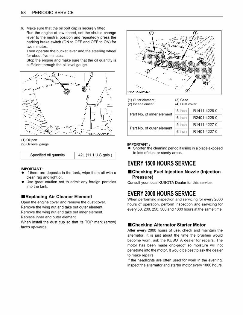
PERIODIC SERVICE58
6. Make sure that the oil port cap is securely fitted. Run the engine at low speed, set the shuttle changelever to the neutral position and repeatedly press theparking brake switch (ON to OFF and OFF to ON) fortwo minutes. Then operate the bucket lever and the steering wheelfor about five minutes. Stop the engine and make sure that the oil quantity issufficient through the oil level gauge.
A If there are deposits in the tank, wipe them all with aclean rag and light oil.
A Use great caution not to admit any foreign particlesinto the tank.
BReplacing Air Cleaner ElementOpen the engine cover and remove the dust-cover.Remove the wing nut and take out outer element.Remove the wing nut and take out inner element.Replace inner and outer element.When install the dust cup so that its TOP mark (arrow)faces up-wards.
A Shorten the cleaning period if using in a place exposedto lots of dust or sandy areas.
EVERY 1500 HOURS SERVICEBChecking Fuel Injection Nozzle (Injection
Pressure)Consult your local KUBOTA Dealer for this service.
EVERY 2000 HOURS SERVICEWhen performing inspection and servicing for every 2000hours of operation, perform inspection and servicing forevery 50, 200, 250, 500 and 1000 hours at the same time.
BChecking Alternator Starter MotorAfter every 2000 hours of use, check and maintain thealternator. It is just about the time the brushes wouldbecome worn, ask the KUBOTA dealer for repairs. Themotor has been made drip-proof so moisture will notpenetrate into the motor. It would be best to ask the dealerto make repairs.If the headlights are often used for work in the evening,inspect the alternator and starter motor every 1000 hours.
(1) Oil port(2) Oil level gauge
Specified oil quantity 42L (11.1 U.S.gals.)
(1) Outer element(2) Inner element
(3) Case(4) Dust cover
Part No. of inner element5 inch R1411-4228-0
6 inch R2401-4228-0
Part No. of outer element5 inch R1411-4227-0
6 inch R1401-4227-0
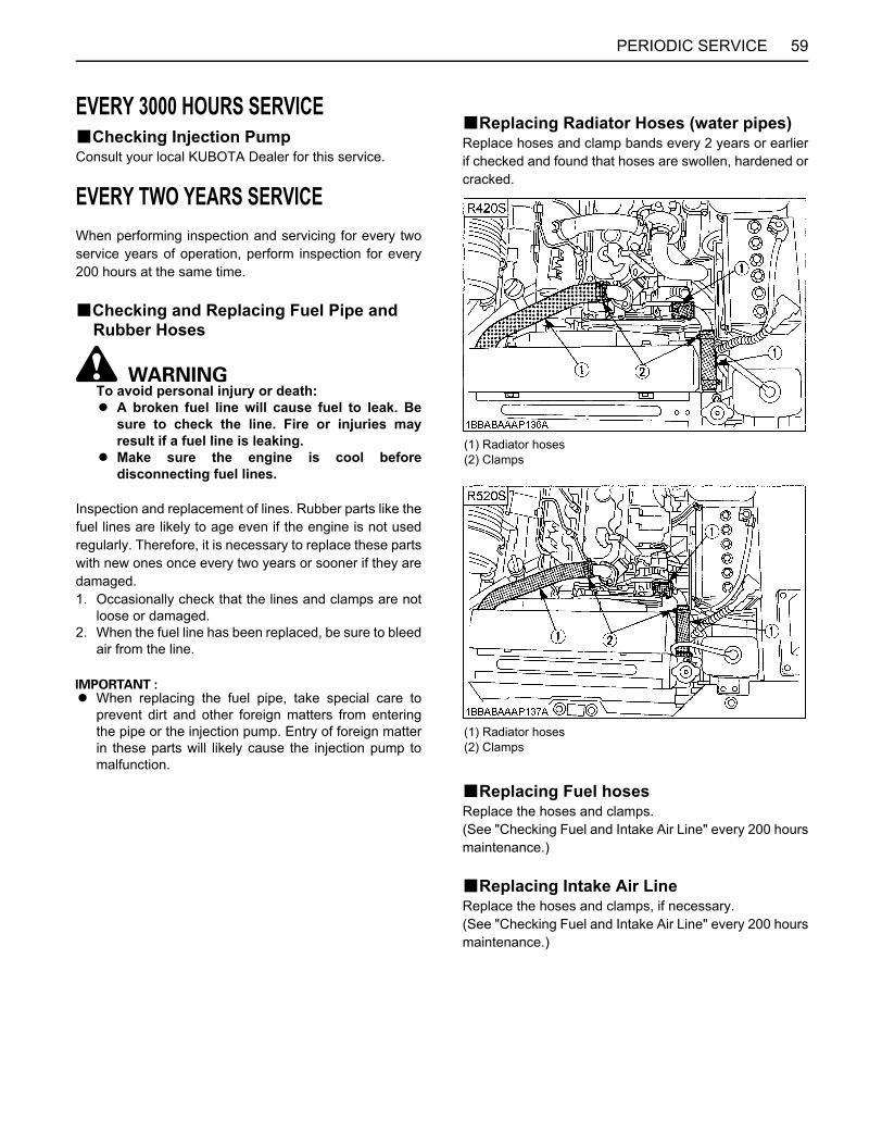
59PERIODIC SERVICE
EVERY 3000 HOURS SERVICEBChecking Injection PumpConsult your local KUBOTA Dealer for this service.
EVERY TWO YEARS SERVICEWhen performing inspection and servicing for every twoservice years of operation, perform inspection for every200 hours at the same time.
BChecking and Replacing Fuel Pipe and Rubber Hoses
To avoid personal injury or death:A A broken fuel line will cause fuel to leak. Be
sure to check the line. Fire or injuries mayresult if a fuel line is leaking.
A Make sure the engine is cool beforedisconnecting fuel lines.
Inspection and replacement of lines. Rubber parts like thefuel lines are likely to age even if the engine is not usedregularly. Therefore, it is necessary to replace these partswith new ones once every two years or sooner if they aredamaged.1. Occasionally check that the lines and clamps are not
loose or damaged.2. When the fuel line has been replaced, be sure to bleed
air from the line.
A When replacing the fuel pipe, take special care toprevent dirt and other foreign matters from enteringthe pipe or the injection pump. Entry of foreign matterin these parts will likely cause the injection pump tomalfunction.
BReplacing Radiator Hoses (water pipes)Replace hoses and clamp bands every 2 years or earlierif checked and found that hoses are swollen, hardened orcracked.
BReplacing Fuel hosesReplace the hoses and clamps.(See "Checking Fuel and Intake Air Line" every 200 hoursmaintenance.)
BReplacing Intake Air LineReplace the hoses and clamps, if necessary. (See "Checking Fuel and Intake Air Line" every 200 hoursmaintenance.)
(1) Radiator hoses(2) Clamps
(1) Radiator hoses(2) Clamps
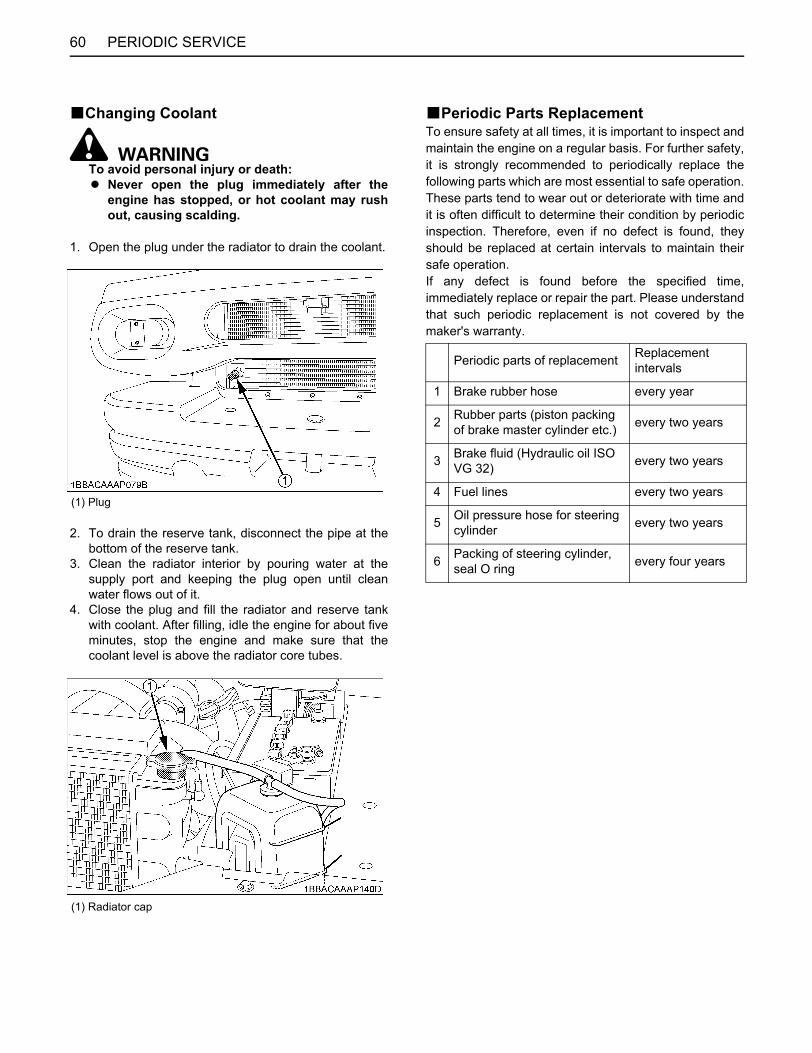
PERIODIC SERVICE60
BChanging Coolant
To avoid personal injury or death:A Never open the plug immediately after the
engine has stopped, or hot coolant may rushout, causing scalding.
1. Open the plug under the radiator to drain the coolant.
2. To drain the reserve tank, disconnect the pipe at thebottom of the reserve tank.
3. Clean the radiator interior by pouring water at thesupply port and keeping the plug open until cleanwater flows out of it.
4. Close the plug and fill the radiator and reserve tankwith coolant. After filling, idle the engine for about fiveminutes, stop the engine and make sure that thecoolant level is above the radiator core tubes.
BPeriodic Parts ReplacementTo ensure safety at all times, it is important to inspect andmaintain the engine on a regular basis. For further safety,it is strongly recommended to periodically replace thefollowing parts which are most essential to safe operation.These parts tend to wear out or deteriorate with time andit is often difficult to determine their condition by periodicinspection. Therefore, even if no defect is found, theyshould be replaced at certain intervals to maintain theirsafe operation.If any defect is found before the specified time,immediately replace or repair the part. Please understandthat such periodic replacement is not covered by themaker's warranty.
(1) Plug
(1) Radiator cap
Periodic parts of replacement Replacement intervals
1 Brake rubber hose every year
2 Rubber parts (piston packing of brake master cylinder etc.) every two years
3 Brake fluid (Hydraulic oil ISO VG 32) every two years
4 Fuel lines every two years
5 Oil pressure hose for steering cylinder every two years
6 Packing of steering cylinder, seal O ring every four years
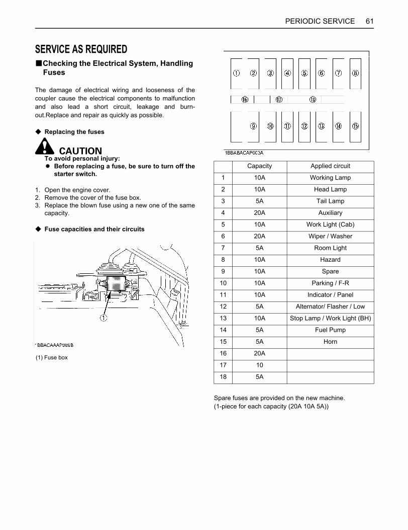
61PERIODIC SERVICE
SERVICE AS REQUIREDBChecking the Electrical System, Handling
Fuses
The damage of electrical wiring and looseness of thecoupler cause the electrical components to malfunctionand also lead a short circuit, leakage and burn-out.Replace and repair as quickly as possible.
C Replacing the fuses
To avoid personal injury:A Before replacing a fuse, be sure to turn off the
starter switch.
1. Open the engine cover.2. Remove the cover of the fuse box.3. Replace the blown fuse using a new one of the same
capacity.
C Fuse capacities and their circuits
Spare fuses are provided on the new machine. (1-piece for each capacity (20A 10A 5A))
(1) Fuse box
Capacity Applied circuit
1 10A Working Lamp
2 10A Head Lamp
3 5A Tail Lamp
4 20A Auxiliary
5 10A Work Light (Cab)
6 20A Wiper / Washer
7 5A Room Light
8 10A Hazard
9 10A Spare
10 10A Parking / F-R
11 10A Indicator / Panel
12 5A Alternator/ Flasher / Low
13 10A Stop Lamp / Work Light (BH)
14 5A Fuel Pump
15 5A Horn
16 20A
17 10
18 5A
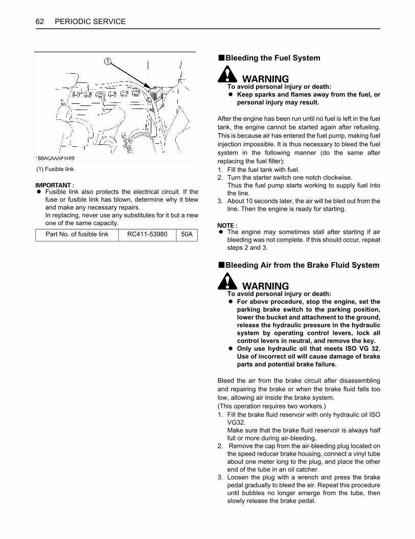
PERIODIC SERVICE62
A Fusible link also protects the electrical circuit. If thefuse or fusible link has blown, determine why it blewand make any necessary repairs. In replacing, never use any substitutes for it but a newone of the same capacity.
BBleeding the Fuel System
To avoid personal injury or death:A Keep sparks and flames away from the fuel, or
personal injury may result.
After the engine has been run until no fuel is left in the fueltank, the engine cannot be started again after refueling.This is because air has entered the fuel pump, making fuelinjection impossible. It is thus necessary to bleed the fuelsystem in the following manner (do the same afterreplacing the fuel filter):1. Fill the fuel tank with fuel.2. Turn the starter switch one notch clockwise.
Thus the fuel pump starts working to supply fuel intothe line.
3. About 10 seconds later, the air will be bled out from theline. Then the engine is ready for starting.
A The engine may sometimes stall after starting if airbleeding was not complete. If this should occur, repeatsteps 2 and 3.
BBleeding Air from the Brake Fluid System
To avoid personal injury or death:A For above procedure, stop the engine, set the
parking brake switch to the parking position,lower the bucket and attachment to the ground,release the hydraulic pressure in the hydraulicsystem by operating control levers, lock allcontrol levers in neutral, and remove the key.
A Only use hydraulic oil that meets ISO VG 32.Use of incorrect oil will cause damage of brakeparts and potential brake failure.
Bleed the air from the brake circuit after disassemblingand repairing the brake or when the brake fluid falls toolow, allowing air inside the brake system. (This operation requires two workers.)1. Fill the brake fluid reservoir with only hydraulic oil ISO
VG32. Make sure that the brake fluid reservoir is always halffull or more during air-bleeding.
2. Remove the cap from the air-bleeding plug located onthe speed reducer brake housing, connect a vinyl tubeabout one meter long to the plug, and place the otherend of the tube in an oil catcher.
3. Loosen the plug with a wrench and press the brakepedal gradually to bleed the air. Repeat this procedureuntil bubbles no longer emerge from the tube, thenslowly release the brake pedal.
(1) Fusible link
Part No. of fusible link RC411-53980 50A
63PERIODIC SERVICE
4. If air is not fully bled by one operation, repeat step 3.5. After the bubbles are completely removed, retighten
the plug and replace the cap.6. Refill the brake fluid reservoir with the ISO VG32
hydraulic oil to the specified level. The brake fluid properties are different frommanufacturer to manufacturer. Use the same brand ofhydraulic oil.
TIRESBHandling Tires
To avoid personal injury or death:A Before handling tires, stop the engine, set the
parking brake switch to the parking position,lower the bucket and attachment to the ground,release the hydraulic pressure in the hydraulicsystem by operating control levers. Lock allcontrol levers in neutral, and remove the key.
A When raising the tire, block up the chassis forsafety.
A Before adding air, have the tire correctlyinstalled on the machine or put the tire in aretaining device (tire inflation cage). Explosiveseparation of the tire can cause serious injury.
(1) Brake fluid reservoir
(1) Air bleeder plug
PERIODIC SERVICE64
BConservation of TiresIf the air pressure in the tire is too high or too low, the lifeof the tire will be shortened.Make routine checks of the air pressure in tires, and adjustso the pressure is correct.Always measure the tire pressure, and check for damageto the tires or rims before starting operation.
C Tire pressure
Make sure the tire size marked on the R420 tire. Then follow above chart.
1. Insufficient tire pressure Too small an amount of air in the tire can cause it tohave excessive slack, which makes for faster wearingdown of the tread.
2. Correct tire pressure3. Excessively high tire pressure
Too high a tire pressure causes the tractive force ofthe machine to decrease, or the tire to slip. There is also the risk of a blow out.
BChanging Tires
C Removal1. Loosen the hub bolts each by one turn on the wheel to
be removed.2. Raise the wheel off the ground, then loosen and
remove the hub bolts and change the tire to a new one.
C Fitting1. Mount wheel to axle and lightly tighten the hub bolts.2. Lower the wheel to the ground, and tighten the hub
bolts to the recommended torque in the order shownabove.
BMounting the TiresLug tires are used to provide strong traction and buoyancyon soft ground. When mounting them, take care toposition their tread pattern in the proper direction.
(1) Deficient(2) Correct(3) Excessive(4) Ground level
Type R420S R520S
Tire size 12.5/70-16-8PR 15.5/60-18-8PR
Front tire
0.26 0.01MPa (36.9 1.4psi)
0.22 0.01MPa (31.2 1.4psi)
Rear tire
0.26 0.01MPa (36.9 1.4psi)
0.22 0.01MPa (31.2 1.4psi)
Tightening torque 275 to 314N-m (203 to 231ft-lb)
(1) Correct(2) Incorrect(3) Forward
65STORAGE
STORAGE
To avoid personal injury or death:A While storing, do the following.
Stop the engine, set the parking brake switch tothe parking position, lower the bucket andattachment to the ground, release the hydraulicpressure in the hydraulic system by operatingcontrol levers, lock all control levers in neutral,and remove the key.
C Before storing the machine for long periods oftime, do the following:
1. Wash and clean each part of the machine, and storethe machine indoors: never leave it outdoors. If it mustbe stored outdoors, choose a flat place, lay planks,park the machine, and cover it completely.
2. Add oil and grease, and change oil.3. Apply grease sufficiently to the piston rods of the oil
pressure cylinders where they are exposed.4. Remove and store the battery separately.5. If there is possibility that temperature may drop below
0 (32 F) during storage, add anti-freeze to thecooling water. See "Mixing ratio between water andanti-freeze" in the HANDLING LOADER IN COLD-WEATHER section.
6. Run the engine, drive the machine for a short distance,and operate the lift arm and bucket.
7. At the same time, recharge battery.
C When using equipment that has not been used fora long time, follow the procedure below.
1. Remove the grease applied to the hydraulic cylinderrod.
2. Run the engine with no load until the attachment drivesystem and the travel system have been thoroughlylubricated.
CAUTION WHEN WASHING THE MACHINEWash the machine after stopping the engine. If you washthe machine while running the engine, splashing water willget into the air cleaner through its intake and causeengine trouble. Carefully, wash and do not splash waterover the air cleaner.
66 TROUBLESHOOTING
TROUBLESHOOTING
ENGINE TROUBLES AND REPAIRSIf there is any question, contact your KUBOTA dealer
Trouble Cause Countermeasure
Starting difficulties
Fuel is too viscous* Check fuel tank and filter * Remove impurities and water * If necessary, replace filter
Air or water in the fuel system.
* Remove water from the fuel tank. * Check fuel pipe joint bolts and nuts for looseness * Purging of the fuel system (for fuel filter and injection pump see "PURGING OF THE FUEL SYSTEM" in the chapter "OTHER ADJUSTMENTS AND REPLACEMENTS".)
Oil viscosity is too high that the engine runs sluggishly in winter
*Pour hot water over the radiator *Use oils of different viscosities depending on the ambient temperature. (Use SAE10W, SAE10W-30 or SAE10W-40)
Battery is almost dead; insufficient compression * Recharge battery
Insufficient engine power
Low fuel level * Check fuel and add if necessary
Clogged air cleaner * Clean the air filter element
Engine suddenly stops Low fuel level * Check fuel and add if necessary
* Purge the fuel system
Abnormal exhaust gas colour
Poor fuel * Use high quality fuel
Too much engine oil * Drain engine oil to prescribed oil level
Water temperature in red zone (Overheating)
Defective seal of the water pump * Replace
Worn or torn fan belt * Adjust or replace
Thermostat is defect * Replace
Coolant level too low * Fill to prescribed level
Radiator grill or fins are clogged * Clean
Coolant is contaminated with rust from the cylinder head or crank case * Replace coolant fluid and add anti-rust
Defective radiator cap (Evaporation) * Replace
Corroded coolant pipes * Clean
Continuous operation under full load * Reduce load
Cylinder head gasket is damaged (Coolant loss) * Replace
Engine oil level too low * Fill to prescribed level
Maladjustment of fuel injection * Readjust ignition timing
Use of poor fuel * Use prescribed fuel
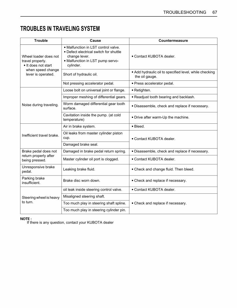
67TROUBLESHOOTING
TROUBLES IN TRAVELING SYSTEM
If there is any question, contact your KUBOTA dealer
Trouble Cause Countermeasure
Wheel loader does not travel properly. It does not start when speed change lever is operated.
Malfunction in LST control valve. Defect electrical switch for shuttle
change lever. Malfunction in LST pump servo-
cylinder.
Contact KUBOTA dealer.
Short of hydraulic oil. Add hydraulic oil to specified level, while checking the oil gauge.
Not pressing accelerator pedal. Press accelerator pedal.
Noise during traveling.
Loose bolt on universal joint or flange. Retighten.
Improper meshing of differential gears. Readjust tooth bearing and backlash.
Worm damaged differential gear tooth surface. Disassemble, check and replace if necessary.
Cavitation inside the pump. (at cold temperature) Drive after warm-Up the machine.
Inefficient travel brake.
Air in brake system. Bleed.
Oil leaks from master cylinder piston cup. Contact KUBOTA dealer.Damaged brake seal.
Brake pedal does not return properly after being pressed.
Damaged in brake pedal return spring. Disassemble, check and replace if necessary.
Master cylinder oil port is clogged. Contact KUBOTA dealer.
Unresponsive brake pedal. Leaking brake fluid. Check and change fluid. Then bleed.
Parking brake insufficient. Brake disc worn down. Check and replace if necessary.
Steering wheel is heavy to turn.
oil leak inside steering control valve. Contact KUBOTA dealer.
Misaligned steering shaft.
Check and replace if necessary.Too much play in steering shaft spline.
Too much play in steering cylinder pin.
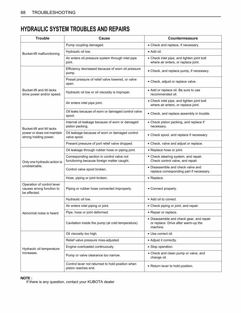
68 TROUBLESHOOTING
HYDRAULIC SYSTEM TROUBLES AND REPAIRS
If there is any question, contact your KUBOTA dealer
Trouble Cause Countermeasure
Bucket-lift malfunctioning
Pump coupling damaged. Check and replace, if necessary.
Hydraulic oil low. Add oil.
Air enters oil pressure system through inlet pipe joint.
Check inlet pipe, and tighten joint bolt where air enters, or replace joint.
Bucket-lift and tilt lacks drive power and/or speed.
Efficiency decreased because of worn oil pressure pump. Check, and replace pump, if necessary.
Preset pressure of relief valve lowered, or valve open. Check, adjust or replace valve.
Hydraulic oil low or oil viscosity is improper. Add or replace oil. Be sure to use recommended oil.
Air enters inlet pipe joint. Check inlet pipe, and tighten joint bolt where air enters, or replace joint.
Oil leaks because of worn or damaged control valve spool. Check, and replace assembly in trouble.
Bucket-lift and tilt lacks power or does not maintain strong holding power.
Internal oil leakage because of worn or damaged piston packing.
Check piston packing, and replace if necessary.
Oil leakage because of worn or damaged control valve spool. Check spool, and replace if necessary.
Present pressure of port relief valve dropped. Check, valve and adjust or replace.
Only one hydraulic action is unobtainable.
Oil leakage through rubber hose or piping joint. Replace hose or joint.
Corresponding section in control valve not functioning because foreign matter caught.
Check steering system, and repair. Check control valve, and repair.
Control valve spool broken. Disassemble and check valve and replace corresponding part if necessary.
Hose, piping or joint broken. Replace.
Operation of control lever causes wrong function to be effected.
Piping or rubber hose connected improperly. Connect properly.
Abnormal noise is heard
Hydraulic oil low. Add oil to correct.
Air enters inlet piping or joint. Check piping or joint, and repair.
Pipe, hose or joint deformed. Repair or replace.
Cavitation inside the pump (at cold temperature) Disassemble and check gear, and repair or replace. Drive after warm-up the machine.
Hydraulic oil temperature increases.
Oil viscosity too high. Use correct oil.
Relief valve pressure miss-adjusted. Adjust it correctly.
Engine overloaded continuously. Stop operation.
Pump or valve clearance too narrow. Check and clean pump or valve, and change oil.
Control lever not returned to hold position when piston reaches end. Return lever to hold position.


UNIVERSAL SYMBOLS
3 Safety Alert Symbol
p Parking Brake
0 Hazard Warning Lights
7 Working Light
E Hydraulic Oil
Lock
, Unlock
As a guide to the operation of your machine, various universal symbols have been utilized on the instruments andcontrols. The symbols are shown below with an indication of their meaning.
Boom Down
Boom Up
Left Swing
Right Swing
Dipperstick Up
Dipperstick Crowd
Bucket Crowd
Bucket Dump
Left Outrigger Down
Left Outrigger Up
Right Outrigger Down
Right Outrigger Up
Slide Lock Lever Lock
Slide Lock Lever Unlock
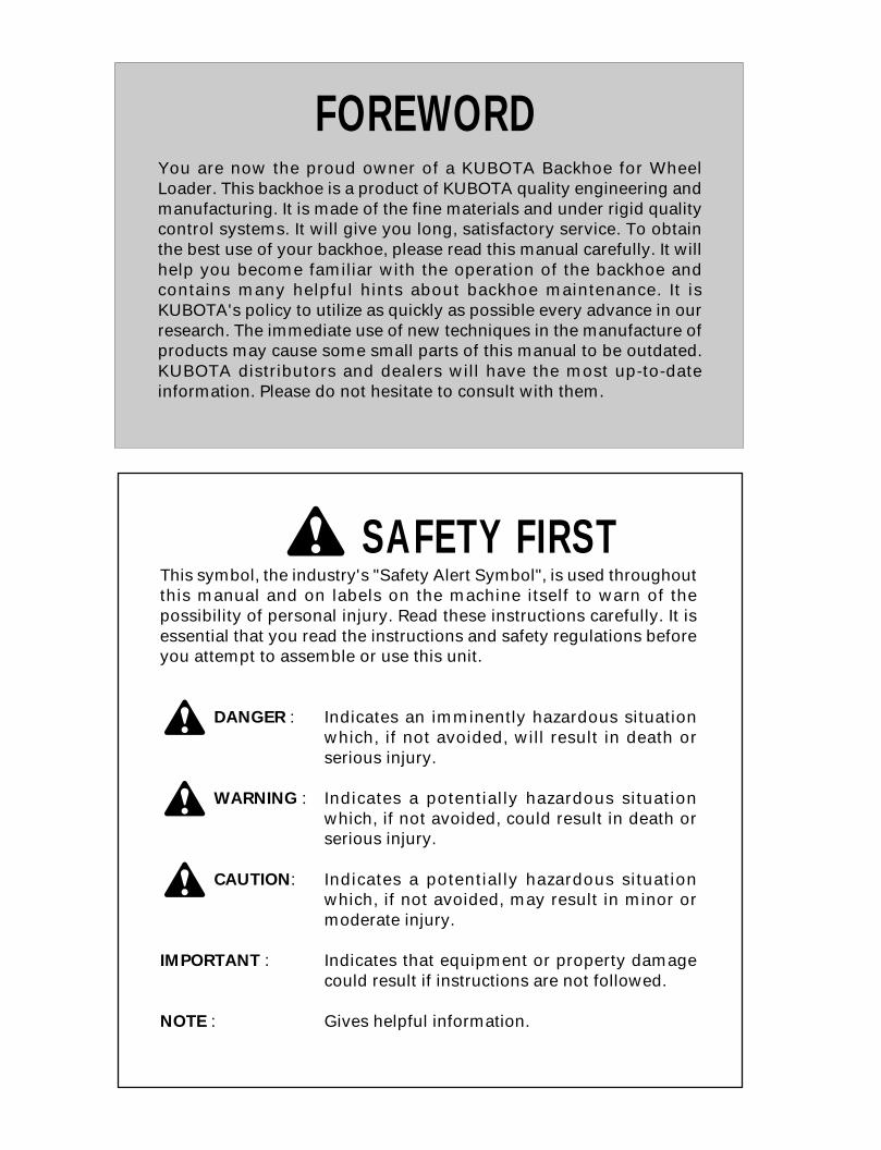
FOREWORD
3 SAFETY FIRSTThis symbol, the industry's "Safety Alert Symbol", is used throughoutthis manual and on labels on the machine itself to warn of thepossibility of personal injury. Read these instructions carefully. It isessential that you read the instructions and safety regulations beforeyou attempt to assemble or use this unit.
3 DANGER : Indicates an imminently hazardous situationwhich, if not avoided, will result in death orserious injury.
3 WARNING : Indicates a potentially hazardous situationwhich, if not avoided, could result in death orserious injury.
3 CAUTION: Indicates a potentially hazardous situationwhich, if not avoided, may result in minor ormoderate injury.
IMPORTANT : Indicates that equipment or property damagecould result if instructions are not followed.
NOTE : Gives helpful information.
You are now the proud owner of a KUBOTA Backhoe for WheelLoader. This backhoe is a product of KUBOTA quality engineering andmanufacturing. It is made of the fine materials and under rigid qualitycontrol systems. It will give you long, satisfactory service. To obtainthe best use of your backhoe, please read this manual carefully. It willhelp you become familiar with the operation of the backhoe andcontains many helpful hints about backhoe maintenance. It isKUBOTA's policy to utilize as quickly as possible every advance in ourresearch. The immediate use of new techniques in the manufacture ofproducts may cause some small parts of this manual to be outdated.KUBOTA distributors and dealers will have the most up-to-dateinformation. Please do not hesitate to consult with them.
CONTENTS
SAFE OPERATION ............................................................................................... 1SPECIFICATIONS....................................................................................................... 1SPECIFICATION TABLE ........................................................................................ 1
PARTS NAMES.......................................................................................................... 2
OPERATING THE BACKHOE................................................................................... 3STARTING............................................................................................................... 3
Operator's Seat.................................................................................................................3SAFETY LEVERS AND APPLIANCE ................................................................... 4
Backhoe Lock Lever .......................................................................................................4Slide Lock Lever .............................................................................................................4
CONTROL LEVERS AND SWITCH...................................................................... 4Backhoe Levers ..............................................................................................................4Outrigger Levers ..............................................................................................................5Backhoe Hand Throttle ...................................................................................................5Working Light Switch ......................................................................................................6
BACKHOE OPERATION ........................................................................................ 6Sliding the Backhoe........................................................................................................7Backhoe operation............................................................................................................8
ATTACHING AND DETACHING THE BACKHOE............................................... 9Detaching the Backhoe...................................................................................................10Attaching the Backhoe....................................................................................................11
TRAVELING........................................................................................................... 13
TRANSPORT BY TRUCK ......................................................................................... 14
MAINTENANCE......................................................................................................... 15
PERIODIC SERVICE................................................................................................. 16DAILY CHECK ....................................................................................................... 16
Grease Fittings ...............................................................................................................16
LIFTING CAPACITY.................................................................................................. 17


1SAFE OPERATION
SAFE OPERATION
This section contains an explanation of how to operate thebackhoe safely. Be sure to read the manual for this machine (wheelloader) before reading the manual for the backhoe. Read and understand this section carefully beforeoperating the backhoe on the wheel loader.All operators, no matter how much experience they mayhave had, should read this and other related manualsbefore operating the machine or any attachment. It is theowner's obligation to instruct all operators in safeoperation.1. Know your equipment and its limitations. Read thisentire manual before attempting to start and operatethe backhoe.
2. Pay special attention to the danger, warning andcaution labels on the backhoe.
1. Before operating the backhoe, be sure to adjust theseat to the backhoe operating position. Any othermethod could result in serious injury. For your safety, ROPS/FOPS (Roll-Over ProtectiveStructures, Falling Objects Protective Structures.) witha seat belt is installed by KUBOTA. Always use seatbelt when the machine is equipped with a ROPS/FOPS.
2. Before starting work, look around the machine tocheck that there are no bystanders or obstacles nearby.
3. The machine's balance changes greatly when thebackhoe is slid. This means that sliding the backhoeon a slope or on irregular terrain increases the chancethat the machine will tip over. Be sure to slide thebackhoe on flat and firm ground to facilitate work andto prevent it from tipping over.
4. When working with a backhoe, lower the outriggersand the loader bucket to stabilize the machine. Lockthe shuttle change lever in neutral, set the parkingbrake switch to the parking position and lock the loaderbucket lever with the loader bucket lever lock on theground. Working with a backhoe without lowering theoutriggers will cause the machine to incline or moveback and forth. This is extremely dangerous.
5. Before moving the machine, always be in the seat(seat in loader position). Raise the loader bucket andoutriggers sufficiently to clear the ground, and thendrive the machine forward. After the machine has been positioned, do the samethings in item 4.
6. Do not dig around the outriggers or tires. If the groundcollapses, the machine may fall into the areaexcavated and result in serious personal injury ordeath.
1. BEFORE OPERATING THE BACKHOE
2. OPERATING THE BACKHOE
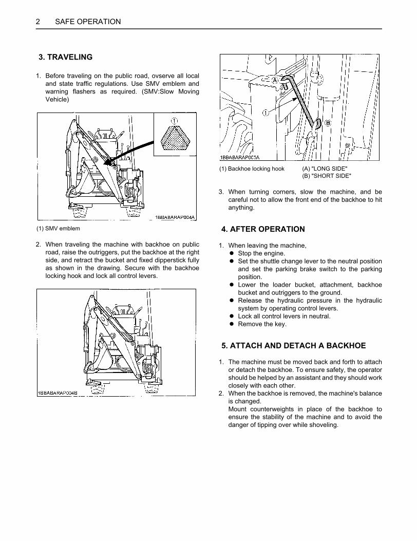
SAFE OPERATION2
1. Before traveling on the public road, ovserve all localand state traffic regulations. Use SMV emblem andwarning flashers as required. (SMV:Slow MovingVehicle)
2. When traveling the machine with backhoe on publicroad, raise the outriggers, put the backhoe at the rightside, and retract the bucket and fixed dipperstick fullyas shown in the drawing. Secure with the backhoelocking hook and lock all control levers.
3. When turning corners, slow the machine, and becareful not to allow the front end of the backhoe to hitanything.
1. When leaving the machine,A Stop the engine.A Set the shuttle change lever to the neutral position
and set the parking brake switch to the parkingposition.
A Lower the loader bucket, attachment, backhoebucket and outriggers to the ground.
A Release the hydraulic pressure in the hydraulicsystem by operating control levers.
A Lock all control levers in neutral.A Remove the key.
1. The machine must be moved back and forth to attachor detach the backhoe. To ensure safety, the operatorshould be helped by an assistant and they should workclosely with each other.
2. When the backhoe is removed, the machine's balanceis changed. Mount counterweights in place of the backhoe toensure the stability of the machine and to avoid thedanger of tipping over while shoveling.
3. TRAVELING
(1) SMV emblem
(1) Backhoe locking hook (A) "LONG SIDE" (B) "SHORT SIDE"
4. AFTER OPERATION
5. ATTACH AND DETACH A BACKHOE
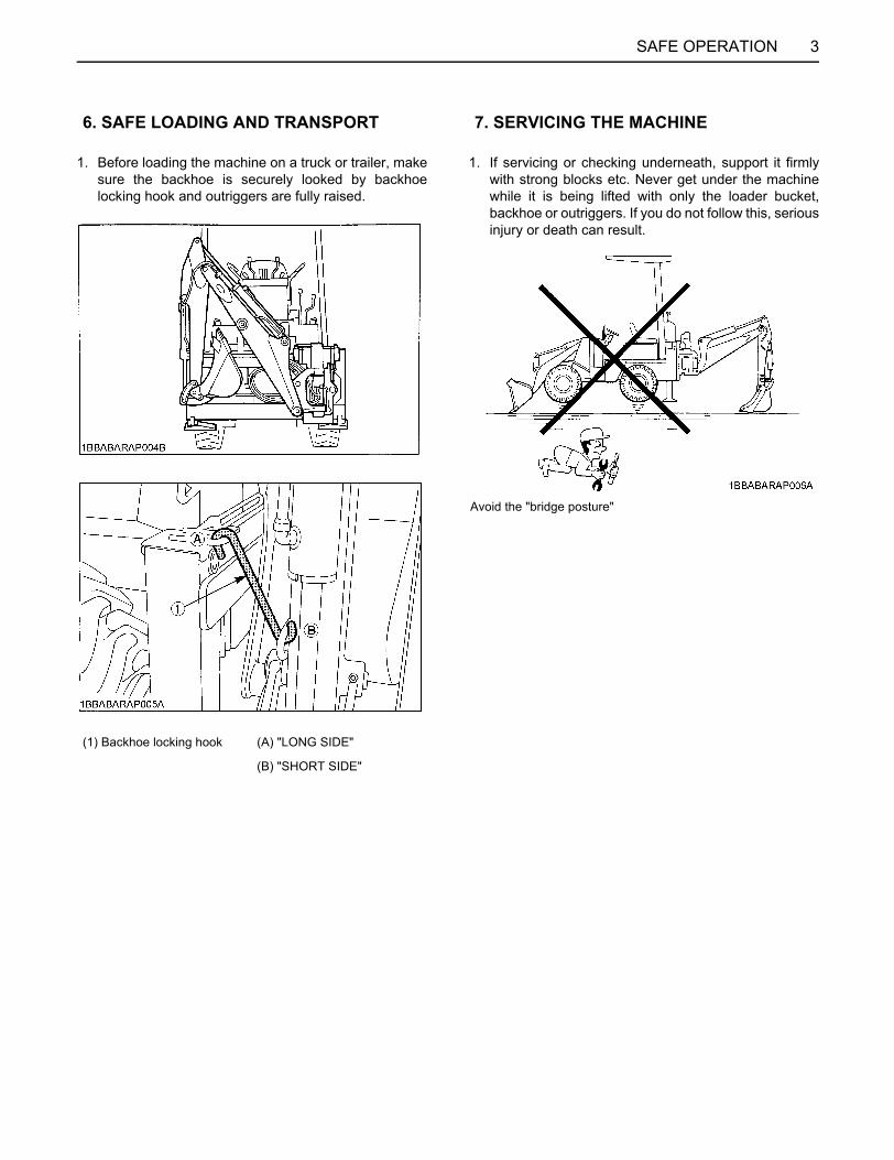
3SAFE OPERATION
1. Before loading the machine on a truck or trailer, makesure the backhoe is securely looked by backhoelocking hook and outriggers are fully raised.
1. If servicing or checking underneath, support it firmlywith strong blocks etc. Never get under the machinewhile it is being lifted with only the loader bucket,backhoe or outriggers. If you do not follow this, seriousinjury or death can result.
6. SAFE LOADING AND TRANSPORT
(1) Backhoe locking hook (A) "LONG SIDE"
(B) "SHORT SIDE"
7. SERVICING THE MACHINE
Avoid the "bridge posture"
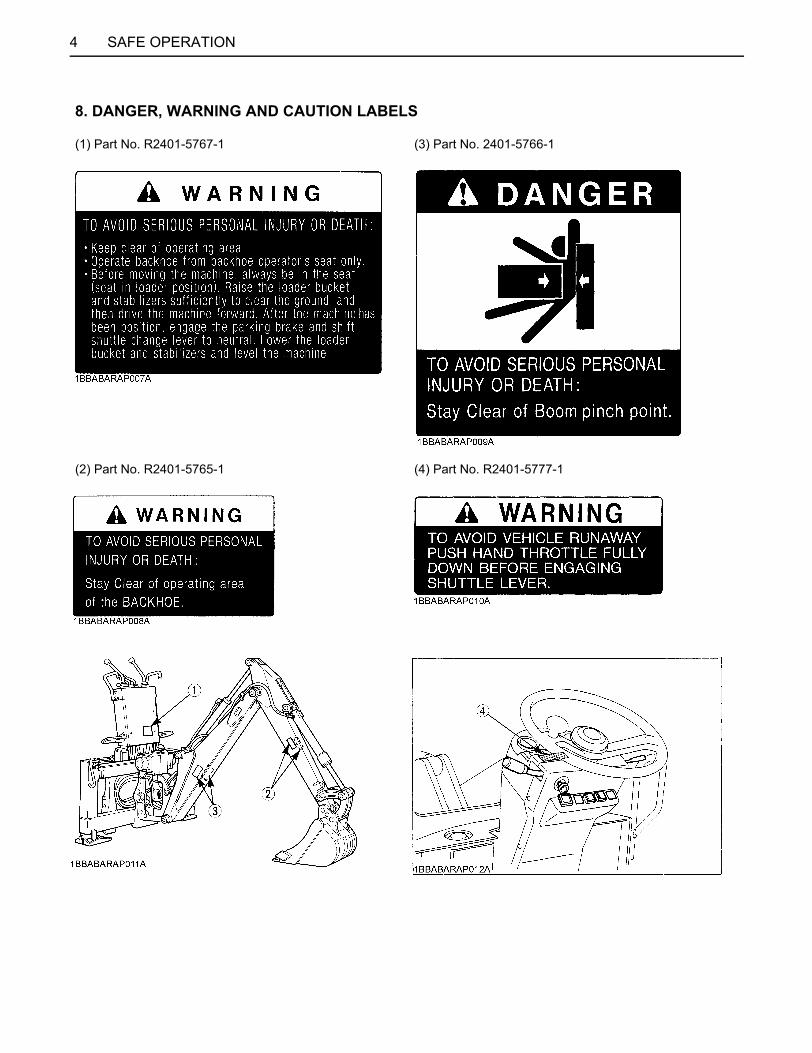
SAFE OPERATION4
8. DANGER, WARNING AND CAUTION LABELS
(1) Part No. R2401-5767-1 (3) Part No. 2401-5766-1
(2) Part No. R2401-5765-1 (4) Part No. R2401-5777-1

5SAFE OPERATION
1. Keep danger, warning and caution labels clean and free from obstructing material.2. Clean danger, warning and caution labels with soap and water, dry with a soft cloth.3. Replace damaged or missing danger, warning and caution labels with new labels from your local KUBOTA dealer.4. If a component with danger, warning and caution label (s) affixed is replaced with new part, make sure new label (s) is
(are) attached in the same location (s) as the replaced component.5. Mount new danger, warning and caution labels by applying on a clean dry surface and pressing any bubbles to outside
edge.
9. CARE OF DANGER, WARNING AND CAUTION LABELS


1SPECIFICATIONS
SPECIFICATIONS
SPECIFICATION TABLEAbove dimensions are based on the machine with JPN Quick Coupler, Standard Loader, ROPS/FOPS Canopy,Backhoe and Standard Backhoe Bucket. JPN = made in Japan Mean Value and value for use on concrete roads are given for tipping load and operating load. Specifications Subject to change without Notice.
Model name R420S R520S
Type Canopy CAB Canopy CAB
Operating weight (with ROPS/FOPS Canopy, CAB) kg(lbs.) 3410(7520) 3660(8070) 3750(8270) 4000(8820)
Tipping Load (Full Turn) kN(lbf) 20.6(4630) 22.8(5130) 22.1(4960) 24.1(5420)
Operating load kN(lbf) 10.3(2315) 11.0(2480)
Overall length mm(in.) 4695(184.8) 5135(202.2)
Backhoe
Max. digging depth mm(in.) 2750(108.3) 2750(108.3)
Max. digging height mm(in.) 3220(126.8) 3220(126.8)
Max. dumping height mm(in.) 2040(80.3) 2040(80.3)
Max. digging radius mm(in.) 3700(145.7) 3700(145.7)
Swing angle Deg 180 180
Width of boom slide mm(in.) 1000(39.4) 1000(39.4)
Bucket capacity (cu.ft) 0.07(2.4) 0.07(2.4)
Bucket width mm(in.) 450(17.7) 450(17.7)
Digging force bucket kN(lbf) 18.2(4100) 18.2(4100)
Digging force dipperstick kN(lbf) 12.3(2755) 12.3(2755)
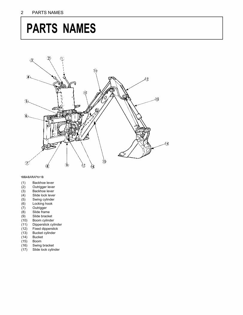
2 PARTS NAMES
PARTS NAMES
(1) (2) (3) (4) (5) (6) (7) (8) (9) (10) (11) (12) (13) (14) (15) (16) (17)
Backhoe lever Outrigger lever Backhoe lever Slide lock lever Swing cylinder Locking hook Outrigger Slide frame Slide bracket Boom cylinder Dipperstick cylinder Fixed dipperstick Bucket cylinder Bucket Boom Swing bracket Slide lock cylinder
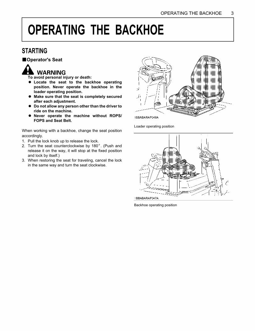
3OPERATING THE BACKHOE
OPERATING THE BACKHOE
STARTINGBOperator's SeatTo avoid personal injury or death:A Locate the seat to the backhoe operating
position. Never operate the backhoe in theloader operating position.
A Make sure that the seat is completely securedafter each adjustment.
A Do not allow any person other than the driver toride on the machine.
A Never operate the machine without ROPS/FOPS and Seat Belt.
When working with a backhoe, change the seat positionaccordingly.1. Pull the lock knob up to release the lock.2. Turn the seat counterclockwise by 180 . (Push and
release it on the way, it will stop at the fixed positionand lock by itself.)
3. When restoring the seat for traveling, cancel the lockin the same way and turn the seat clockwise.
Loader operating position
Backhoe operating position
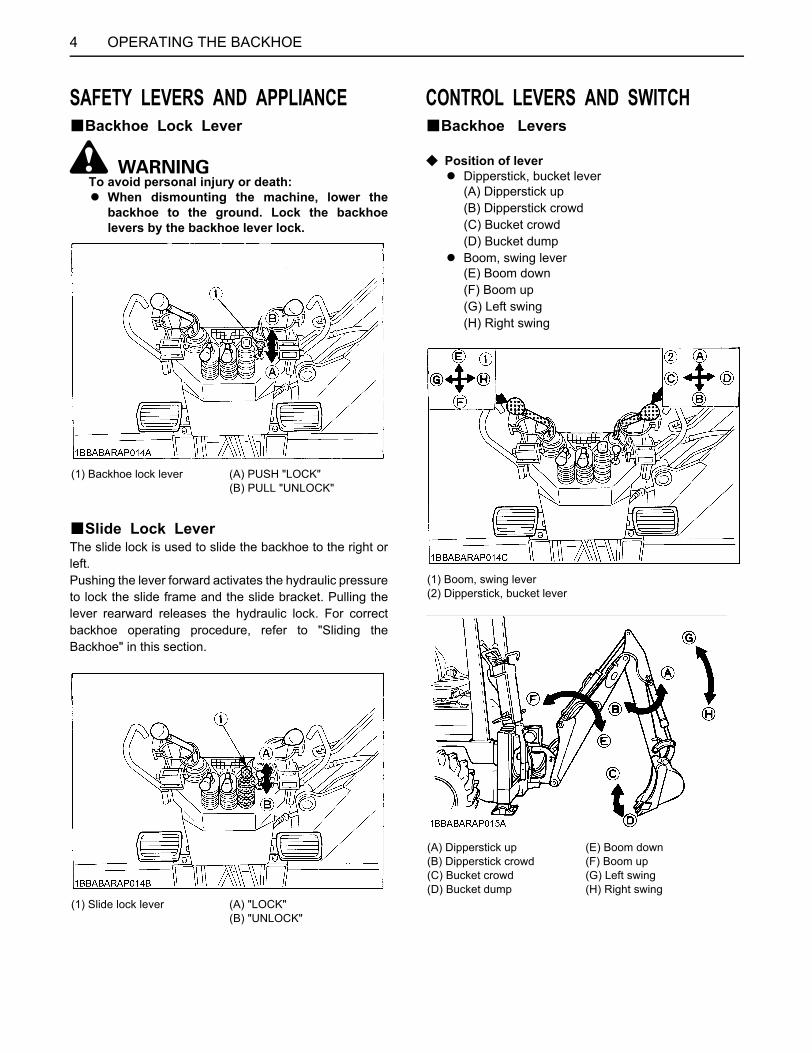
OPERATING THE BACKHOE4
SAFETY LEVERS AND APPLIANCEBBackhoe Lock Lever
To avoid personal injury or death:A When dismounting the machine, lower the
backhoe to the ground. Lock the backhoelevers by the backhoe lever lock.
BSlide Lock LeverThe slide lock is used to slide the backhoe to the right orleft. Pushing the lever forward activates the hydraulic pressureto lock the slide frame and the slide bracket. Pulling thelever rearward releases the hydraulic lock. For correctbackhoe operating procedure, refer to "Sliding theBackhoe" in this section.
CONTROL LEVERS AND SWITCHBBackhoe Levers
C Position of leverA Dipperstick, bucket lever
(A) Dipperstick up(B) Dipperstick crowd(C) Bucket crowd(D) Bucket dump
A Boom, swing lever(E) Boom down(F) Boom up(G) Left swing(H) Right swing
(1) Backhoe lock lever (A) PUSH "LOCK"(B) PULL "UNLOCK"
(1) Slide lock lever (A) "LOCK"(B) "UNLOCK"
(1) Boom, swing lever(2) Dipperstick, bucket lever
(A) Dipperstick up (E) Boom down(B) Dipperstick crowd (F) Boom up(C) Bucket crowd (G) Left swing(D) Bucket dump (H) Right swing
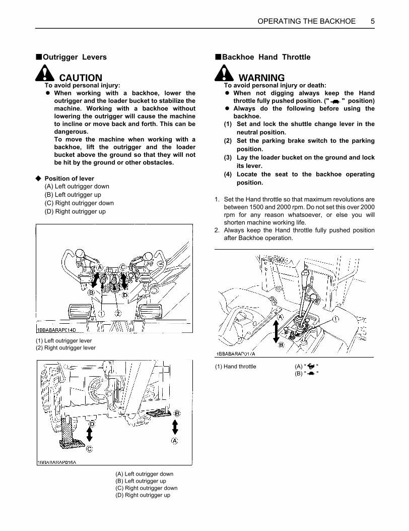
5OPERATING THE BACKHOE
BOutrigger Levers
To avoid personal injury:A When working with a backhoe, lower the
outrigger and the loader bucket to stabilize themachine. Working with a backhoe withoutlowering the outrigger will cause the machineto incline or move back and forth. This can bedangerous.To move the machine when working with abackhoe, lift the outrigger and the loaderbucket above the ground so that they will notbe hit by the ground or other obstacles.
C Position of lever(A) Left outrigger down(B) Left outrigger up(C) Right outrigger down(D) Right outrigger up
BBackhoe Hand Throttle
To avoid personal injury or death:A When not digging always keep the Hand
throttle fully pushed position. (" " position)A Always do the following before using the
backhoe.(1) Set and lock the shuttle change lever in the
neutral position.(2) Set the parking brake switch to the parking
position.(3) Lay the loader bucket on the ground and lock
its lever.(4) Locate the seat to the backhoe operating
position.
1. Set the Hand throttle so that maximum revolutions arebetween 1500 and 2000 rpm. Do not set this over 2000rpm for any reason whatsoever, or else you willshorten machine working life.
2. Always keep the Hand throttle fully pushed positionafter Backhoe operation.
(1) Left outrigger lever(2) Right outrigger lever
(A) Left outrigger down(B) Left outrigger up(C) Right outrigger down(D) Right outrigger up
(1) Hand throttle (A) " "(B) " "
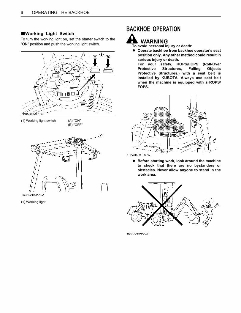
OPERATING THE BACKHOE6
BWorking Light SwitchTo turn the working light on, set the starter switch to the"ON" position and push the working light switch.
BACKHOE OPERATION
To avoid personal injury or death:A Operate backhoe from backhoe operator's seat
position only. Any other method could result inserious injury or death. For your safety, ROPS/FOPS (Roll-OverProtective Structures, Falling ObjectsProtective Structures.) with a seat belt isinstalled by KUBOTA. Always use seat beltwhen the machine is equipped with a ROPS/FOPS.
A Before starting work, look around the machineto check that there are no bystanders orobstacles. Never allow anyone to stand in thework area.
(1) Working light switch (A) "ON"(B) "OFF"
(1) Working light
7OPERATING THE BACKHOE
A When leaving the machine,(1) Stop the engine. (2) Set the shuttle change lever to the neutral
position and set the parking brake switch tothe parking position.
(3) Lower the loader bucket, attachment, thebackhoe bucket and outriggers to the ground.
(4) Release the hydraulic pressure in thehydraulic system by operating control levers.
(5) Lock all control levers in neutral.(6) Remove the key.A When working with a backhoe, lower the
outriggers and the loader bucket to stabilizethe machine. Lock the shuttle change lever inneutral set the parking brake switch to theparking position and lock the loader bucketlever with the loader bucket lever lock on theground. Working with a backhoe withoutlowering the outriggers will cause the machineto incline or move back and forth. This isextremely dangerous.
A Never get under the machine while it is beinglifted with only the bucket, backhoe, oroutriggers when servicing or checkingunderneath. Support it firmly with strong blocks, etc. If youdo not follow this, serious injury or death canresult.
A Before moving the machine, always be in theseat (seat in loader position). Raise the loaderbucket and stabilizers sufficiently to clear theground, and then drive the machine forward. After the machine has been position, lower theoutriggers and the loader bucket, lock theshuttle change lever in neutral, set the parkingbrake switch to the parking position and lockthe loader bucket lever with the loader bucketlever lock.
BSliding the BackhoeThis backhoe is provided with a digging section that canslide to the right and left to allow side-digging.1. Place the machine on flat ground, extend the
outriggers so that slide frame is level and the wheelsare slightly lifted off the ground.
2. Swing the boom in the direction opposite to thedirection you wish to slide until it touches the rubbercushion.
3. Set the slide lock lever in the RELEASE position torelease hydraulic lock between the slide frame and theslide bracket.
4. Lower the bucket, and move the boom, dipperstickand bucket operating levers so that the bucket pushesthe ground away. Repeat this operation to slide thebackhoe to the desired position. Depending on the work situation the backhoe can beslid in such a way that the bucket digs into the groundand pulls in the soil.
5. When the backhoe has been slid to the desiredposition, set the slide lock lever to the LOCK position.Shift the bucket lever left side until relief valve works,hold the bucket lever for a couple of seconds whilerelief valve is working. Repeat this action a couple oftimes, then hydraulic slide lock will be set.

OPERATING THE BACKHOE8
6. Finally, move the dipperstick and bucket to make surethat the hydraulic lock is activated.
A Always lock the slide lock lever. Otherwise, thebackhoe will be unstable during work resulting inpossible damage.
BBackhoe operation
C Standard Digging Posture1. Lower the outriggers and loader bucket to stable the
machine.
2. Lock the shuttle change lever in neutral set the parkingbrake switch to the parking position and lock the loaderbucket lever with the loader bucket lever lock on theground.
3. Slide the backhoe so that it aligns with the center lineof the machine, then firmly secure it using the slidelock lever.
4. Operate the outrigger levers so that the outriggerssupport some of the machine weight.
5. Run the engine at the proper speed that matches thework, and start digging.
A Never use the bucket in such a way that its side strikesan object by swinging the bucket boom. Also, do notuse the bucket to drive pipes. Such action can damagethe digging section.
C Ditch digging1. Position the machine so that it aligns with the center
line of the ditch to be digged.2. Lower the outriggers and the loader bucket.3. Dig the ditch by operating the backhoe levers.4. Move the machine step by step taking into
consideration the bucket's dumping reach andproceed in digging.
To avoid personal injury or death:A Do not dig around the outriggers or tires. If the
ground collapses, the machine may fall into thearea excavated and result in serious personalinjury or death.
A When moving the machine to proceed with digging,always lift the outriggers above the ground.
9OPERATING THE BACKHOE
C Digging on a slopeWhen digging a ditch along a slope, start digging from thetop of the ditch and proceed downhill. When digging a ditch along a contour line, first scrape offthe shoulder of the slope so as to keep the machine level.Dig only after a safe, level place is secured for themachine.
C When digging a long ditchWhen digging a long continuous ditch, keep a constantdepth and use the longest dumping reach so that thenumber of stops-and-goes is minimized as much aspossible.
C When side-diggingWhen digging a ditch along an obstacle such as a wall,move the digging section of the backhoe to that direction.
ATTACHING AND DETACHING THE BACKHOE
To avoid personal injury or death:A When the backhoe is removed, the machine's
balance is changed. Mount counterweights in place of the backhoeto ensure the stability of the machine and toavoid the danger of tipping over whileshoveling.
A The machine's balance changes greatly whenthe backhoe is slid. This means that sliding thebackhoe on a slope or on irregular terrainincreases the chance that the machine will tipover. Be sure to slide the backhoe on flat andfirm ground to facilitate work and to prevent itfrom tipping over.
A To prevent the machine from tipping over,position the backhoe in the center of the slideframe.
A If the backhoe is detached from the machineand left unused, retract the outriggers asshown in the Fig. to ensure a safe posture andlock the backhoe operating lever.
A When the backhoe is detached from themachine, immediately mount counterweightsin its place. This ensures safety whenshoveling.
OPERATING THE BACKHOE10
BDetaching the Backhoe1. Run the engine at low speeds.2. Position the backhoe in the center of the slide frame.3. Locate the machine on flat ground.4. Extend the outriggers so that their floats approach the
ground, but do not touch it.5. Operate the dipperstick, boom and bucket so that the
bucket just slightly touches the ground. Do not pressthe bucket against the ground, too strongly or thewheels will lift off the ground.
6. Pull out the backhoe locking snap pins and lock pinson both sides.
A Temporarily store these pins by fitting them in theholes on the backhoe.
7. Extend the outriggers so that the pin on the slide frameis 1 to 3 cm (0.4 to 1.2 in.) from the rear frame bracket.
8. Slowly move the machine forward by graduallypressing accelerator pedal so that its backhoemounting hook is separated 1 to 10 cm (0.4 to 3.9 in.)from the backhoe.
A Since the hydraulic oil piping is still connected, themachine should be moved very little when movingforwards so as not to pull the hose tight.
9. Slowly retract the outriggers fully to settle the backhoe.
A Should the slide frame tilt forward or backward at thistime, operate the boom and dipperstick levers tomaintain a proper, safe posture. Then retract theoutriggers.
(1) Float
(1) Lock pin(2) Snap pin
(1) Rear frame (A) 1 to 3 cm(2) Slide frame (0.4 to 1.2 in.)
(1) Rear frame (A) 1 to 10 cm(2) Slide frame (0.4 to 3.9 in.)
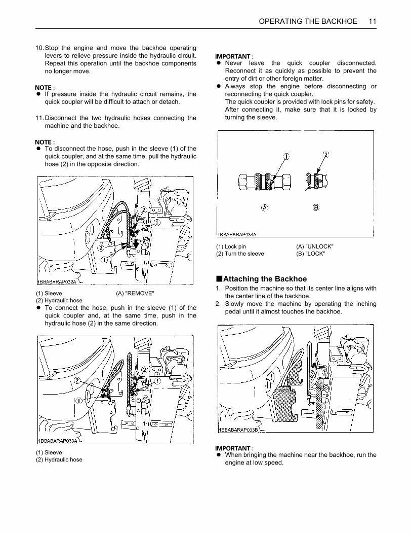
11OPERATING THE BACKHOE
10.Stop the engine and move the backhoe operatinglevers to relieve pressure inside the hydraulic circuit.Repeat this operation until the backhoe componentsno longer move.
A If pressure inside the hydraulic circuit remains, thequick coupler will be difficult to attach or detach.
11.Disconnect the two hydraulic hoses connecting themachine and the backhoe.
A To disconnect the hose, push in the sleeve (1) of thequick coupler, and at the same time, pull the hydraulichose (2) in the opposite direction.
A To connect the hose, push in the sleeve (1) of thequick coupler and, at the same time, push in thehydraulic hose (2) in the same direction.
A Never leave the quick coupler disconnected.Reconnect it as quickly as possible to prevent theentry of dirt or other foreign matter.
A Always stop the engine before disconnecting orreconnecting the quick coupler. The quick coupler is provided with lock pins for safety. After connecting it, make sure that it is locked byturning the sleeve.
BAttaching the Backhoe1. Position the machine so that its center line aligns with
the center line of the backhoe.2. Slowly move the machine by operating the inching
pedal until it almost touches the backhoe.
A When bringing the machine near the backhoe, run theengine at low speed.
(1) Sleeve (A) "REMOVE"(2) Hydraulic hose
(1) Sleeve(2) Hydraulic hose
(1) Lock pin (A) "UNLOCK"(2) Turn the sleeve (B) "LOCK"
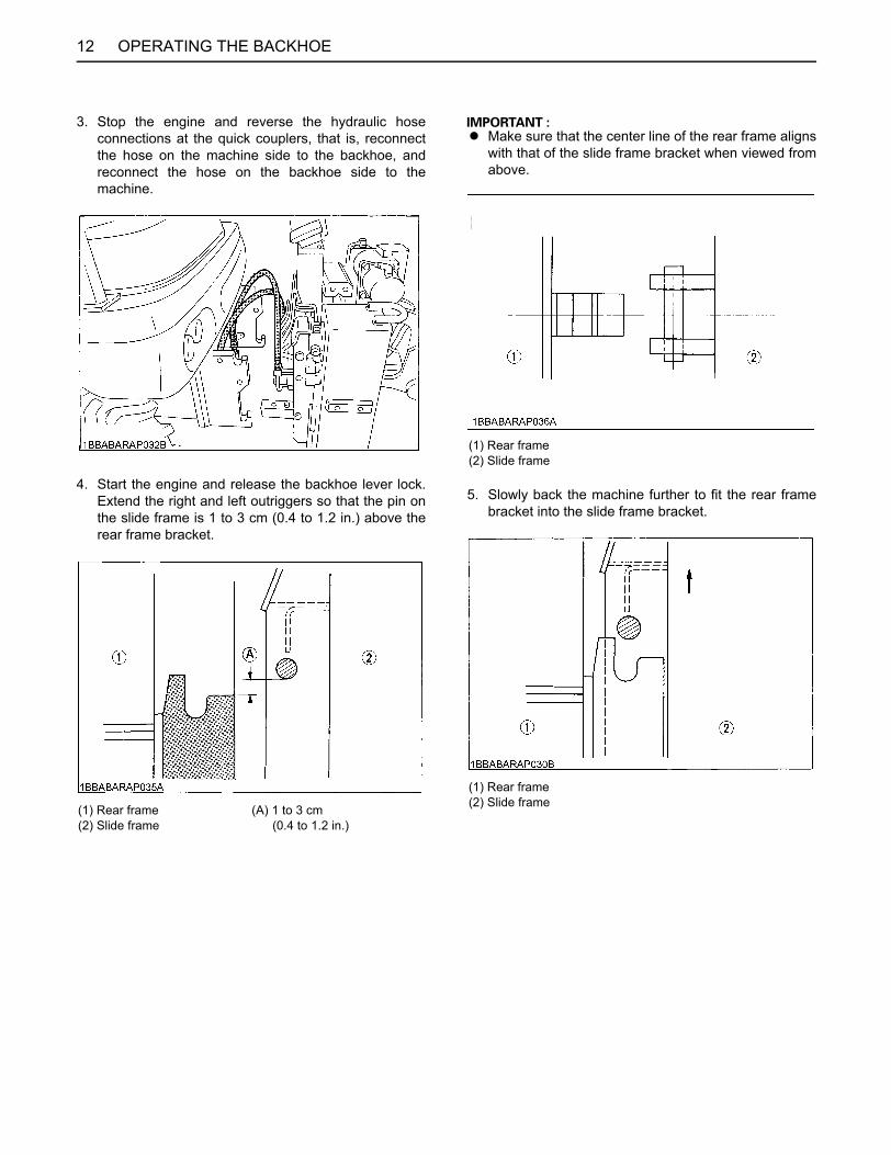
OPERATING THE BACKHOE12
3. Stop the engine and reverse the hydraulic hoseconnections at the quick couplers, that is, reconnectthe hose on the machine side to the backhoe, andreconnect the hose on the backhoe side to themachine.
4. Start the engine and release the backhoe lever lock.Extend the right and left outriggers so that the pin onthe slide frame is 1 to 3 cm (0.4 to 1.2 in.) above therear frame bracket.
A Make sure that the center line of the rear frame alignswith that of the slide frame bracket when viewed fromabove.
5. Slowly back the machine further to fit the rear framebracket into the slide frame bracket.
(1) Rear frame (A) 1 to 3 cm(2) Slide frame (0.4 to 1.2 in.)
(1) Rear frame(2) Slide frame
(1) Rear frame(2) Slide frame
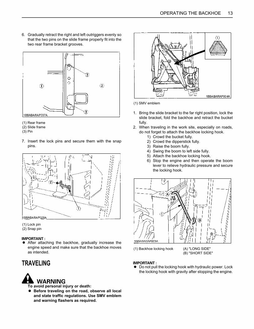
13OPERATING THE BACKHOE
6. Gradually retract the right and left outriggers evenly sothat the two pins on the slide frame properly fit into thetwo rear frame bracket grooves.
7. Insert the lock pins and secure them with the snappins.
A After attaching the backhoe, gradually increase theengine speed and make sure that the backhoe movesas intended.
TRAVELING
To avoid personal injury or death:A Before traveling on the road, observe all local
and state traffic regulations. Use SMV emblemand warning flashers as required.
1. Bring the slide bracket to the far right position, lock theslide bracket, fold the backhoe and retract the bucketfully.
2. When traveling in the work site, especially on roads,do not forget to attach the backhoe locking hook.
1) Crowd the bucket fully.2) Crowd the dipperstick fully.3) Raise the boom fully.4) Swing the boom to left side fully.5) Attach the backhoe locking hook.6) Stop the engine and then operate the boom
lever to relieve hydraulic pressure and securethe locking hook.
A Do not pull the locking hook with hydraulic power. Lockthe locking hook with gravity after stopping the engine.
(1) Rear frame(2) Slide frame(3) Pin
(1) Lock pin(2) Snap pin
(1) SMV emblem
(1) Backhoe locking hook (A) "LONG SIDE"(B) "SHORT SIDE"
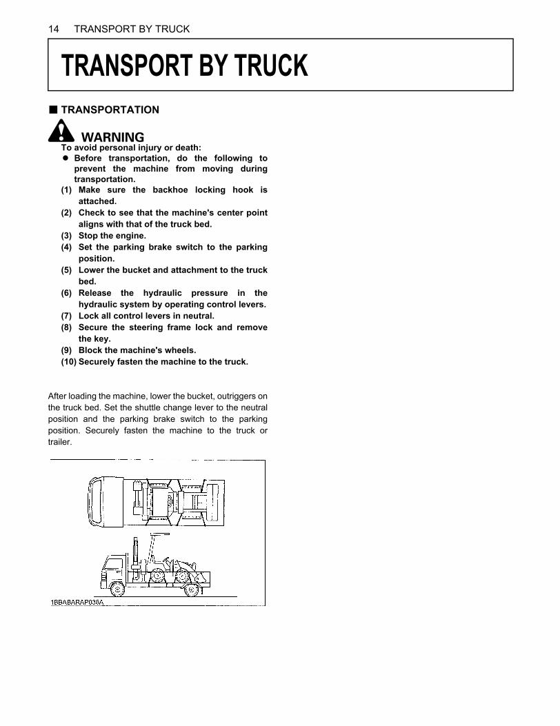
14 TRANSPORT BY TRUCK
TRANSPORT BY TRUCK
B TRANSPORTATIONTo avoid personal injury or death:A Before transportation, do the following to
prevent the machine from moving duringtransportation.
(1) Make sure the backhoe locking hook isattached.
(2) Check to see that the machine's center pointaligns with that of the truck bed.
(3) Stop the engine.(4) Set the parking brake switch to the parking
position.(5) Lower the bucket and attachment to the truck
bed.(6) Release the hydraulic pressure in the
hydraulic system by operating control levers.(7) Lock all control levers in neutral.(8) Secure the steering frame lock and remove
the key.(9) Block the machine's wheels.(10) Securely fasten the machine to the truck.
After loading the machine, lower the bucket, outriggers onthe truck bed. Set the shuttle change lever to the neutralposition and the parking brake switch to the parkingposition. Securely fasten the machine to the truck ortrailer.
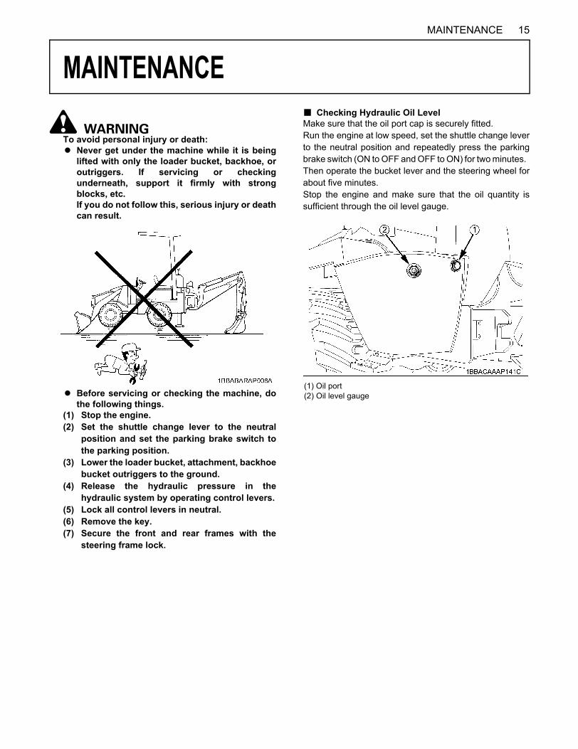
15MAINTENANCE
MAINTENANCE
To avoid personal injury or death:A Never get under the machine while it is being
lifted with only the loader bucket, backhoe, oroutriggers. If servicing or checkingunderneath, support it firmly with strongblocks, etc. If you do not follow this, serious injury or deathcan result.
A Before servicing or checking the machine, dothe following things.
(1) Stop the engine.(2) Set the shuttle change lever to the neutral
position and set the parking brake switch tothe parking position.
(3) Lower the loader bucket, attachment, backhoebucket outriggers to the ground.
(4) Release the hydraulic pressure in thehydraulic system by operating control levers.
(5) Lock all control levers in neutral. (6) Remove the key.(7) Secure the front and rear frames with the
steering frame lock.
B Checking Hydraulic Oil LevelMake sure that the oil port cap is securely fitted. Run the engine at low speed, set the shuttle change leverto the neutral position and repeatedly press the parkingbrake switch (ON to OFF and OFF to ON) for two minutes. Then operate the bucket lever and the steering wheel forabout five minutes. Stop the engine and make sure that the oil quantity issufficient through the oil level gauge.
(1) Oil port(2) Oil level gauge
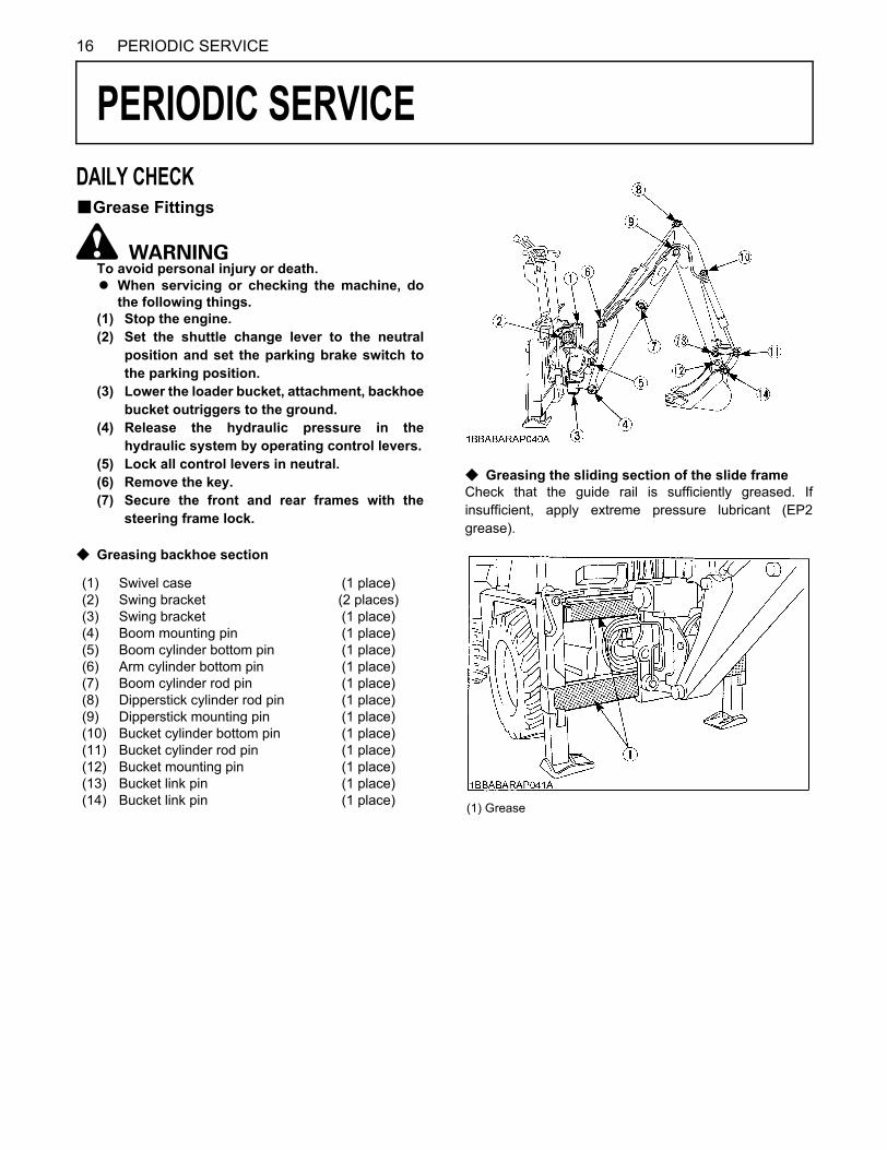
16 PERIODIC SERVICE
PERIODIC SERVICE
DAILY CHECKBGrease FittingsTo avoid personal injury or death.A When servicing or checking the machine, do
the following things.(1) Stop the engine.(2) Set the shuttle change lever to the neutral
position and set the parking brake switch tothe parking position.
(3) Lower the loader bucket, attachment, backhoebucket outriggers to the ground.
(4) Release the hydraulic pressure in thehydraulic system by operating control levers.
(5) Lock all control levers in neutral.(6) Remove the key.(7) Secure the front and rear frames with the
steering frame lock.
C Greasing backhoe section
C Greasing the sliding section of the slide frameCheck that the guide rail is sufficiently greased. Ifinsufficient, apply extreme pressure lubricant (EP2grease).
(1) (2) (3) (4) (5) (6) (7) (8) (9) (10) (11) (12) (13) (14)
Swivel case Swing bracket Swing bracket Boom mounting pin Boom cylinder bottom pin Arm cylinder bottom pin Boom cylinder rod pin Dipperstick cylinder rod pin Dipperstick mounting pin Bucket cylinder bottom pin Bucket cylinder rod pin Bucket mounting pin Bucket link pin Bucket link pin
(1 place) (2 places) (1 place) (1 place) (1 place) (1 place) (1 place) (1 place) (1 place) (1 place) (1 place) (1 place) (1 place) (1 place) (1) Grease
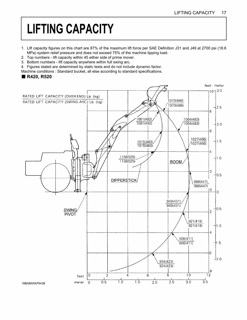
17LIFTING CAPACITY
LIFTING CAPACITY
1. Lift capacity figures on this chart are 87% of the maximum lift force per SAE Definition J31 and J49 at 2700 psi (18.6MPa) system relief pressure and does not exceed 75% of the machine tipping load.2. Top numbers - lift capacity within 45 either side of prime mover.3. Bottom numbers - lift capacity anywhere within full swing arc.4. Figures stated are determined by static tests and do not include dynamic factor.Machine conditions : Standard bucket, all else according to standard specifications.B R420, R520