Embed Size (px)
Citation preview
UNIVERSAL COAL DEVELOPMENT I - KANGALA COLLIERYCO-DISPOSAL COAL DISCARD FACILITY
DESIGN REPORTREPORT REF: TBS-201904002-UCKC
REPORT PREPARED BY CONSULTANT PREPARED FOR CLIENT
110 GRIFFITHS ROAD,
EQUESTRIA,
PRETORIA EAST, 0184
TEL: +2782 093 4969
467 FEHRSEN STREET
BROOKLYN
PRETORIA,0001
TEL: +27 028 3685
UNIVERSAL COAL DEVELOPMENT I – KANGALA COLLIERY CO-DISPOSAL COAL DISCARDFACILTY DESIGN REPORT
Report date: March 2019
Report ref: TBS-201904002-UCKC
Prepared by: Triage Business Services (Pty) Ltd
Reg no. 2016/042672/07
Geotechnical engineering services
Geo-environmental engineering services
Project management services
Mobile: +27 (0) 82 093 0061
Email: [email protected]
Website: http://www.triagebusiness.co.za
Mr. K. K. Mnisi
Director: Triage Business Services (Pty) Ltd.
Mr C. Fourie
Design Reviewer: Eco Elementum Engineering (Pty) Ltd
Pr. Eng Registration:
Doc: TBS-201904002-UCKC
Date: 12/04/2019
Revision: Revision 0
Approved by: KK MNISI
Page i
Table of Content
1 Introductions .................................................................................................................. 2
1.1 Scope of work ......................................................................................................... 2
2 Site Description.............................................................................................................. 2
2.1 Site Locality ............................................................................................................ 3
2.2 Topography............................................................................................................. 4
3 Geology ......................................................................................................................... 4
4 Available information...................................................................................................... 5
5 Site Conditions............................................................................................................... 5
5.1 Surface water.......................................................................................................... 5
5.2 Groundwater ........................................................................................................... 5
5.3 Geotechnical profile ................................................................................................ 5
5.4 Topography............................................................................................................. 6
6 Material Properties......................................................................................................... 6
6.1 Clay for barrier system............................................................................................ 6
6.2 Geomembrane........................................................................................................ 6
6.3 Liner protection ....................................................................................................... 7
6.4 Waste (Coal Discard).............................................................................................. 7
6.4.1 Coarse material ............................................................................................... 7
6.4.2 Fines................................................................................................................ 7
7 Performance Criteria...................................................................................................... 7
8 Design considerations.................................................................................................... 8
8.1 Subsurface drainage............................................................................................... 8
8.2 Floor and side slopes.............................................................................................. 8
Doc: GEO-IXE-005
Date: 11/05/2017
Revision: Revision 1.0
Approved by: M MABALA
Page 2
1 Introductions
Triage Business Services was appointed by Universal Coal PLC to design a co-disposal
discard facility that will accommodate the expansion of the mining into the neighbouring
Middlebult and Eloff block mines. The facility will be taking approximately 14Mt of both coarse
discard and slurry from the plant.
1.1 Scope of work
The scope can be summarised as follows;
Design a co-disposal discard facility that will comply with current legislative
requirements
Produce a Design Report that will form part of the requirement for an Integrated
Water Use Licence application
Produce a Construction Quality Assurance (CQA) document
Doc: GEO-IXE-005
Date: 11/05/2017
Revision: Revision 1.0
Approved by: M MABALA
Page 3
2 Site Description
2.1 Site Locality
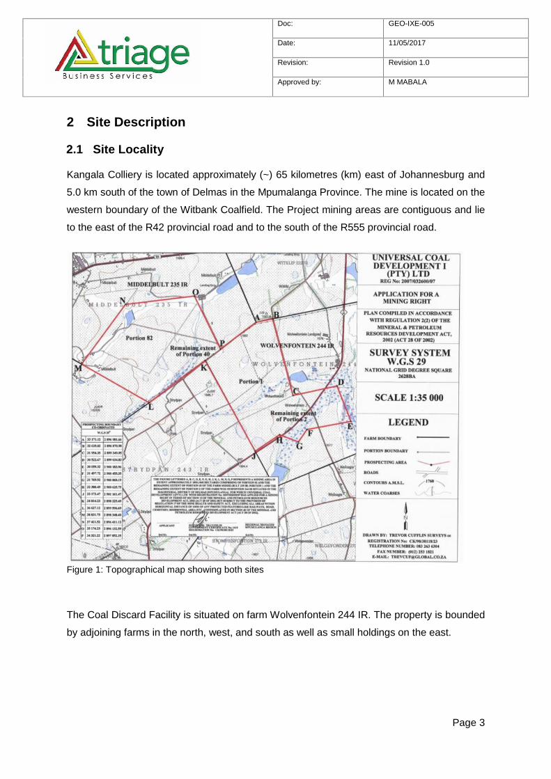
Kangala Colliery is located approximately (~) 65 kilometres (km) east of Johannesburg and
5.0 km south of the town of Delmas in the Mpumalanga Province. The mine is located on the
western boundary of the Witbank Coalfield. The Project mining areas are contiguous and lie
to the east of the R42 provincial road and to the south of the R555 provincial road.
Figure 1: Topographical map showing both sites
The Coal Discard Facility is situated on farm Wolvenfontein 244 IR. The property is bounded
by adjoining farms in the north, west, and south as well as small holdings on the east.

Doc: GEO-IXE-005
Date: 11/05/2017
Revision: Revision 1.0
Approved by: M MABALA
Page 4
2.2 Topography
The topography of the site is slightly undulating with the lowest elevation at 1,567 metres
above sea level (masl) and the highest elevation at 1,597 masl. The Kangala and Middelbult
resources are separated by a perennial drainage channel that runs in a south-west to north-
east direction with a second perennial drainage channel running on the western side of
Middelbult also in a northwestern direction and joins with the perennial drainage that separates
Kangala and Middelbult. The mining areas on both project areas fall outside of the 100-year
flood line of this stream.
3 Geology
The area is characterised by undulating pre-Karoo paleo-topographic terrain. Some of these
basement outcrops are indicated on the geological map and are predominantly of the
Proterozoic Transvaal Supergroup. The underlying basement consists of dolomite and chert
of the Malmani Group and typically displays karst features.
The site geology is characterised by hillwash, colluvium, aeolian deposits, alluvium, pedogenic
materials and residual soils which overlie weathered shales and sandstones of the Vryheid
Formation – refer to Figure 2
Figure 2: 1:250 000 Geological Map
Doc: GEO-IXE-005
Date: 11/05/2017
Revision: Revision 1.0
Approved by: M MABALA
Page 5
4 Available information
The following information was available
1: 50 000 scale topographical maps
1:250 000 scale geological map of both sites
Proposed Kangala Colliery Conceptual Study Report
Geotechnical Study Report
5 Site Conditions
5.1 Surface water
The site is located approximately 1,6 km away from a water course and outside the 1:100 year
floodline. The regional rainfall averages 710mm and regional average annual evaporation of
1600mm. The required design storm intensities and average rainfall are given in table below
24 Hour Rainfall (mm)
1:20 Year 1:50 Year 1:100 Year
118 146 170
5.2 Groundwater
No shallow groundwater was encountered during the geotechnical investigations to the depth
of 4,5m though a present ferricrete layer and nodules may indicate a perched water table.
5.3 Geotechnical profile
Depth to pebble marker: None
Transported soil: Hillwash, colluvium, Aeolian deposits, alluvium and pedogenic
material
Residual soil: weathered shales and sandstones of the Vryheid Formation
Depth to hard rock: 4,5m
Doc: GEO-IXE-005
Date: 11/05/2017
Revision: Revision 1.0
Approved by: M MABALA
Page 6
Foundation rock description: sedimentary Karoo Series underlain at 70 m depth by
dolomitic intrusions
Collapsible structures: not undermined, nor collapsible matrix present
Bearing capacity and consolidation: 5MPa and 40mm under 900 KPa
Seismicity: 0,15 G
5.4 Topography
The topography of the site is moderately flat with an elevation level variance of only 20 metres
(m) over the project area, which is representative of the entire region. Elevation on the site is
highest towards the south western part of the project area at 1,597 masl and the lowest point
being located on the north western boundary of the site at 1,567 masl.
There is a small, non-perennial stream, which runs between Kangala and the Middelbult
resource in a south to north direction. The stream drains in a northern direction from the site.
The project area has a gentle gradient for the bulk of the site. The minimum slope for waste
containment facilities base liners to be 1v:50h (2%).
6 Material Properties
6.1 Clay for barrier system
The clay on site that will be used as a compacted clay liner (CCL) has the following properties;
PI:10 to 18,
Linear shrinkage: 4 to 9.4
Standard Proctor density and OMC 1563 to 1779kg/m3 MDD and 18 to 22% OMC
Percentage clay: Selected
Maximum particle size: 100% passing 13,5mm sieve
Permeability: less than 9,27x10⁻⁷cm/s
Minimum Shear strength: c=5KPa and ignored and phi=18 degrees
6.2 Geomembrane
The geomembrane used on the barrier system will comply with SANS 1526 for High Density
Polyethylene (HDPE)
Doc: GEO-IXE-005
Date: 11/05/2017
Revision: Revision 1.0
Approved by: M MABALA
Page 7
6.3 Liner protection
A silty sand layer is proposed as the liner protection and shall have 100% passing 0,475mm
sieve particle size distribution
6.4 Waste (Coal Discard)
6.4.1 Coarse material
Particle size distribution: Broadly graded rock fill greater than 75mm
Strength phi=34 degrees and C=0 KPa
Free draining
Density: 1800 kg/m3
6.4.2 Fines
Density: 1120 to 1140 kg/m3
Particles size distribution: 200 micron
7 Performance Criteria
The CDF design conforms to the criteria set below
Minimum factor of safety for rock dumps: 1.5
Frequency of overtopping: less than once in 50 years on average
Action leakage rate: 20l/ha/day
Strain limitation in GM less than 3%
The waste is assessed as type 3 waste (According to NEMWA 2013 Regulation 635). The
waste is acid forming and has the potential for spontaneous combustion.
There were tests done for interface shear strength therefore parameters are assumed based
on the extract from GRI Report number 30. The values are to be validated by the construction
quality assurance (CQA)
Doc: GEO-IXE-005
Date: 11/05/2017
Revision: Revision 1.0
Approved by: M MABALA
Page 8
8 Design considerations
Due to the geotechnical profile and presence of a ferricrete layer within the excavation depth
below natural ground level (NGL), a perimeter subsurface drain is provided on the upslope
side of the coal discard facility (CDF).
8.1 Subsurface drainage
The subsurface drainage system will comprise of a typical herringbone drainage with a central
pipe leading into a manhole on the outside of the facility.
8.2 Floor and side slopes
The geotechnical profile allows for excavation to a depth of 1,5m within the highly weathered
residual soil zone, and thus a minimum slope of 2% across the floor area will be provided.
While material of the excavated material varies, it is not practical to place clay on a 1v:3h side
slope (which has an incline of 18 degrees) as this influences veneer stability, and clay
compaction energy requirements, as well as permeability. The inner side slopes of the
perimeter wall will thus be 1v:4h.
The outer slopes of the perimeter embankment are selected taking rehabilitation into
consideration and optimising structural stability as well as costs. An outer slope of 1v:3H is
possibly the least suitable slope for rehabilitation by grassing due to high maintenance
requirements for erosion mitigation. Experience in embankment dam engineering and in
particular coal mine rehabilitation in northern KZN has shown side slopes of 1v:5h and are
required if grassing is required for erosion protection. The on-site available material is however
broadly graded and will be selected to have the semi-pervious material in the outer zone for
both stability (increasing permeability towards the outer shell and erosion resistance of the
surface.) Thus to minimise embankment volumes and related costs of materials placement
and maintenance, an outer slope of 1v:2,0H is chosen. The crest width is 3m for construction
practicality and slopes towards the inside with a 1% fall. Maximum crest height is 1,5m above
NGL
Due to the waste rock material being broadly graded and variable, provision is made for
perimeter paddocks of 0,5 m depth and 6m width to retain potentially polluted stormwater run-
Doc: GEO-IXE-005
Date: 11/05/2017
Revision: Revision 1.0
Approved by: M MABALA
Page 9
off the operational period (and serve as an initial silt trap) with overflow leading to the existing
polluted stormwater dam via concrete lined channel.
The concept design for the barrier system which comprises both drainage and liners
recognises the available material for the CCL is variable in permeability and marginal, with a
high risk of coarse fraction that will induce point load tensile strains in the adjacent
geomembrane under the design load. It is suggested that a GCL is used a partial replacement
of the CCL to provide both a protection function and contribute to seepage control. The site
material will yield adequate liner protection by making use of sandy silt and silty sand with
layer thickness influenced by the mean which by the pioneering layer is placed. The use of a
semi-pervious silty material as a pioneering layer is selected for not only strain limitation, but
also to reduce the risk of introducing air at a foundation level to minimise the risk of
spontaneous combustion. A specified soil envelope is used in the 300mm thick layer above
the liner prior to placement of discard. The discard is to be placed on the perimeter zone in
advance of the inner tailings, maintaining a minimum freeboard of 800mm at all times.
The waste is programme to have a saturated central deposition with the perimeter dry placed
material in an upstream construction. Decant is intended to be a combination of surface decant
by floating barge with a base liner drainage layer intended to remain saturated. The intent of
the saturated lower portion is to protect the barrier system from temperature effects in the
event of spontaneous combustion, and clogging due to ultra-fines. Thus herringbone drains
lead to a perimeter hill ring-drain which itself decants 0,8m below the liner level to an external
collector pipe system that drains under gravity to the PCD.
In Conclusion the barrier system from the base upwards is 200mm rip and re-compact the in-
situ material after excavation, to meet the grades required. Place one layer of selected silty
clay to specification, recognising the variability in PI and permeability. Thereafter place a GCL
and Geomembrane followed by a 300mm thick specified sandy silt ballast and protection layer.
This ballast thickness is required to overcome potential panel shrinkage and provide
immediate confining stress to the GCL, with simultaneous elimination of wrinkles in the GM
due to the bar method of placement. This layer is compacted with a single pass of smooth
drum roller following which the herringbone finger drain system is installed and allowed to be
Doc: GEO-IXE-005
Date: 11/05/2017
Revision: Revision 1.0
Approved by: M MABALA
Page 10
submerged after placement of the pioneering waste layer. The decant pipe details maintain
at least 1m pressure depth above the composite liner, but drain freely under gravity to the
external leachate management system. The external system is an HDPE pipe that drains
under gravity to the PCD.
The operational phase requires placement in accordance with the drawings which specify
material properties within the zones varying from coarse on the outside through a gradation to
fines on the insides. The outer slope stability is dependent on operational compliance. The
outer slope has an eventual overall slope of 1v:3H with intermediate step backs of 4m width
to accommodate slope drainage after every 15m of vertical rise i.e at 15m and 30m above
NGL. Theses step back berms serve an additional precautionary function in the unlikely event
of overtopping or seepage through side walls.
Instrumentation is to be provided to confirm performance. Movement monitoring beacons will
be installed at each bench, making provision for monitoring of points of intersection by survey
i.e at corners with intermediate beacons set to monitor by line of sight. Onsite rainfall records
are maintained. Return flow volumes are measured by a combination of flow meters on decant
pumps and either a flow meter on the external return water drainage pipe or by means of a v-
notch at the entrance to the PCD. The subsurface drainage system monitoring will include
both flow rates and water quality records.
Doc: GEO-IXE-005
Date: 11/05/2017
Revision: Revision 1.0
Approved by: M MABALA
Page 11
APPENDIX A: DESIGN DRAWINGS
1. P17-08-D02: GENERAL LAYOUT PLAN2. P17-08-D03: PHASE 1-GENERAL LAYOUT3. P17-08-D04: PHASE 2-GENERAL LAYOUT4. P17-08-D05: FINAL FILL MODEL LAYOUT PLAN5. P17-08-D06: LONG SECTION & CROSS SECTION6. P17-08-D07: TYPICAL SECTIONS & BERM DETAILS7. P17-08-D08: TYPICAL LINER DETAILS8. P17-08-D09: MANHOLE, SUBSOIL DRAIN PIPES & PIPE LINER PENETRATION