Embed Size (px)
Citation preview
IIIIIIIIIIIIIIIIIIIIIIIIIIIIIIIIIIIIIIIIIIIIIIIIIIIIIIIIIIIIIIIIIIIIIIIIIIIUS010876315B2
(12) United States PatentPichon et al.
(10) Patent NO.: US 1058765315 B2(45) Date of Patent: Dec. 29, 2020
(54) DKVICK l(OR K)(TILA()TION OF S)VIVIMIN(2POOL CLEANING DEVICE
(71) Applicant. ZODL(C POOL CARE EUROPE,Paris (I'R)
(72) Inventors Philippe Pichon. Viileneuve de Riviere(FR): Simon Dua'aut. Castelginest(I'lt); Philippe Blanc-Tailleur,Toul ouse (FR)
Rcfcrcnccs ('itcd
U S PA'l l:N'I D(X'UMEN IS
(56)
(52) U.S. CI.CPC ............... E04H 4//44 (2013.01): B6//If 7/00
(2013.01): E04H 4/2654 (2013.01)(58) lrield of ()lassification Search
CPC ........ B60M 7/00, E04H 4/144, E04H 4/1654.E04H 4/082, E04H 4/101, B63B 27/143,
(Con(IUUed)
(73) Assignee: ZODIAC POOL CARE EUROPE.Bron (FR)
("
) Notice Subject to any disclaimer„ the term of tluspatent is extended or adjusted under 35U S C. 154(b) by 2 days.
(21) Appl. No 15/3()6,379
(22) PCT Filed Oct. 14, 2016EP%0
6.565,29) D2 e 5(2003 Desmoobns
6.616396 D2 e 9(2003 Steinberg
(Con(IUUcd)
FOREIC)N PATENT DOCUMENTS
2860"29 4I20150.06(850 7,i2003
(Con(IUUed)
B23(2 5i26340gilo
B60P Ii4314(4I538
(86) PCT Noc PCT/FR2016/052655
6 371 (c)(1),(2) Date. Oct. 24, 2016
(87) PCT Pub. Noc WO2017/064433
PCT Pub. Date: Apr. 20, 2017
(65) Prior Publication Data
US 2017/0268250 Al S«7(. 21, 2017
O'I'I IER PUl31 I( A1 IONS
Iatwnational Ps(cat Applwatioo No 0('1 I 820(6 052655, Interna-tional Se ucb Recoil and tpnuen Opinion, dated .lan 26, 2017. 13
pti es
(Con(IUUcd)
Prtmarv Eiammer Mark T Le(74) du«racy, .(Sea/, «r Kiri«gilpatrick I'ownsend 8.Stockton LLP; Dean W. Russell
(30) Foreign Application Priority Data(5 /) ABSTRACT
Oct 14, 2015 (lilt)
(51) Int. CLB606f 7/00E04H 4//4E()4II 4/I6
(200G.01)(200G.01)(2006 01)
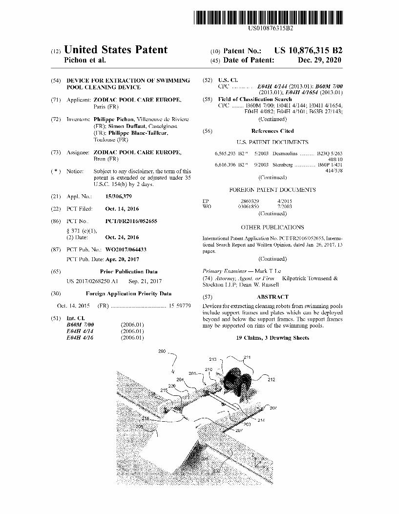
15 59779 Devi ccs for extrac(utg clc ming robots from sw Imnung poolsinclude support frames and plates which can bc deploy«xibeyond mid below die support I'ramcs The support framesmay be supported on rime of the swimming pools.
19 Claims, 3 Drawing Sheets
209
12
20i
US 10,S76,31i B2Page 2
/58) Field of (:lassilicatinn 'SearchCPC ............ B63B 35/40; BG3B 2027/165: B63B
2708/00: BG3B 27/36; B63B 2205/06,B60P I.'43, B60P I/64S4. B60P I/00,B60P I.'433: B60P I/43S. B60P 3/06,
B60R 9/06See application tile for complete search history
/56) References Cited
U.S. PATENT DOCUMENTS
2011(0008140 Al "'r2011 Hansen... A61G 3 061414(523
201(,i((0676(S Al 3,i2011 Rooney, HI ct al2014'026308 Al 9"2014 Rensad e( «I.2018 0208278 A(* 7 20 1 8 Klehanoo H04H 4 1654
WOWO
FOREIGN PATENT DOCUMENTS
03087501 10 20032012135538 10r2012
O'I'Ill:It PUIII,I( AfIONS
I R15(9779, "Notice of Decision to Giant", dated Sep 8, 2017. 2
pagesFiench Patent Application No 1559779, French Search Repoit,doled Aug 8, 2016. 7 pages
* cited by examiner
U.S. Patent Dec. 29,2020 Sheet 1 of 3 US 10,876,315 B2
101
05
102
2tlt
Fig. 2
U.S. Patent Dec. 29,2020 Sheet 2 of 3 US 10,876,315 B2
200
204
210
Fig. 4
U.S. Patent Dec. 29,2020 Sheet 3 of 3 US 10,876,315 B2
200
100
202
US 10,8761
DEVICE FOR EXTRACTION OF S)VIVIVIINGPOOL CLEANING DEVICE
CROSS-REFERENCE TO RELATEDAPPI.I('ATIONS
This is a U S national phase under 35 U.S.C. 371 ofInten&ational Patent Application No. PCT/FR2016/052655,titled "Dispositif D'Extraction D'I Jn Appareil Nettoyeur dePiscu&c" and liled Oct. 14, 2016, which clmms pnonty to &ii
and bcnclil ol'French Patent Application No. 1559779. titled*'Dispositif I)'I&xtraction O'Un Appareil Nettoyeur dePiscine" and tiled Oct 14, 2015. the entirety of both ofwhich is incorporated herein by reference.
The present invention relates to the field of equipment for &1
s&vinuning pools. More particularly. it concerns a device forcxl&'acl&on ol &I swunnung pool cleinlhlg ih:vlcc fioat w&ncr,
or lor puuu&g 0 u&to water.
PREAMBLE AND PRIOR ART 20
Thc u&vent&on conccms cqu&pnlcnl which I'&cihl»tcs lhcimplementation of a surface cleaniog, device submerged u& aliquid, such as a surface founed by the walls of a pool, inparticular a swimming pool A cleaning device of this typeis commonly a mobile swimming pool cleanin robot. Theseswimming pool mbots l&nve replaced the re ular, or evenda&ly. task ol'cleanu&g thc bottom and walls of a swmuningpool. winch suunm&ng pool users were previously obhgedIo can I Out &0
S&vimmin pool cleaning robots of this type travel alongthe bottom and optionally the lateral walls of a s&vimn&ing
pool. removin the debris. dust or particles adhering to thewalls by means of bnishes and a water suction c&rcuitcompris&ng a litter. Thc&r travel on thc bouom of the pool &s 1&
aulonuii&c. and w op&un&sed to clem& Ihe complelc surfaceduru&g 0 cleanu&g cycle Ol approx&mately onc lo lwo hours.'I'hese automimous robots have provided swimming poolusers &vith significant convenience A swimming pool robotaccording to the poor art, ac has just been described, &s 40
illustrated in FILI. 1.Ai regular intervals, or generally al Ihe cnd of a cleaning
cycle. il remains necessary lo remove lhc clca&un robotfrom the pool, for cx ample &n order to clean Ihe filter or s!orcthe robot v hen it &1 not being used In addition. studies shovthat the mbots are generally taken out by the user becausethey impede swinm&ing. or for fear of the combination ofwater and electric&ty.
Exuacuon ol'lm etc&ming roboi Ircqucntly poses prob-lems for Ihc user, &n particular concerning the luuc taken for 0
thc extraction aud slomgc of thc robol wluch can last forn&ore than ten minutes or so, substantial efiort to be nlade inorder to raise the robot, associated mainly with the volumeof water contained. as v ell as windi»g of the cable arounditself, or also problems of size when the cleaning robot &s &.
cxirac&&xl Irom the water Thc morc frequently Ihc litter mustbc» ashed. tlu: more acute the problem becomes. Fu&ally, thcfacts of ha&ing lo rcmove thc clca&ung robot from &Is
habitual storage. put it &n the w:ster, then remove it from thewater at the end of the cycle and store it. lead many users to rcreduce their use of the robot in practice. It is thereforedesirable to provide cleaning robots of tl»s type with evengreater autonomy, u& part&cuter as fares putting Ihcm into thepool or extract&ng them from Ihc pool arc conccmcd.
In order to aumnpl to solve tlus problem, dev&ces for s&
storage of a swimming pool robot are k&x&wn, such asdescribed for example in patent application l&R 2 742 351
,315 B2
tiled &n Dccembcr 1995. In lius systmu. a devwc for extrac-tion of a cieaning robot comprises a crane in a verticalpos&lion, pmvnlcd al &ts m&d w&th a hook wh&ch &s dcsigncxtto cooperate &vith a ring supported on a cleaning mbot inorder 10 hoist &I fioni thc pool.
A system of this type is ho&vever inconvenient to use,requiun a certain anniunt of dexterity by the user, since thehook of the crane has to cooperate with the nng of the robotwhen the latter is at the level of the water 1&ne. In addition,tlus extraction dcv&ce can be adapted only lo a Iiu&i&est
number of robots wluch support a hook„so as to be able tobc cxtraclcd I'rom Ihc water by the crane. Fu&ally, the usernn&st be present throughout the operation, including whenthe clean&ng robot is put back into llm water.
l)evices ti&r extraction of a sv imn&mg pool cleaning robotare also known. such as the one descnbed in the Europeanpatent application lip 2 g60 329. Such a device comprises apool cleanin robot interface like a holder system that isarranged to bc coupled to Ihe clca&ung robot duru&g an ex&t
process inciudin extraction of the cleaning robot from thepool, and a pool clc;ming robot man&pulator such as a
meehan&cal arm, coupled to the pool cleaning robot interfaceand»rn&aged Io mo&esnid pool cleauu&g robot interfacebclw&mn a pos&t&on whcrmn the robot &s u&side thc pool anda position wherein the robot is outside the pool
Such a device comprises a serious pool congestion dis-advantage mainiy due to the pool cleaning robot interface.
It is also kno&vn a device for the stowage of vessel hullcleaning robot as described in the United States patentappl&cation US 2011/0067615. 11»s dcv&cc compo&ca astow»gc comparuncnt for slowu&g Ihc hull robot and arotation system for rotatinu the stowage con&partment rela-tive to the vessel between a launclv'recovery attitude and astowed position
The objective of the invention is in part&cular to eliminatesome of the aforementioned disadvantages.
SUMMARY Ol'I III: INVI:N1 ION
According to a first aspect„ the invention relates to adcv&ce li&r extraction of a su inuning pool clcamug robot.
Thc cxlracuon dcv&ce compr&ses:a support frame,a plate which can be deployed beyond the support fra&ne
and belov, the tatter:means for controlling the deployment of the plate.It v ill be appreciated tl&nt the plate is designed to be
placed such as to have onc ol its longitud&nal &xlgcs placcxtsubstant&ally on thc edge 01'he support I'ramc. and thc otheredge placed below Ihc surface of thc water &n the suinunu&gpool
I'he plate has a generally fiat fi&rn&. and has sutficieotrigid&ty to support the weight of the cleaning robot duringthe extraction of the robot from the swimming pool. In otherwords, when the clc;ming robot is pos&t&oned Ou thc plme,thc laltcr re&a&ns its generally tlat lonn.
Thc plate composes a rollu&g surface wluch &s dcsigncdfor rolling of the cleaning robot when the cleaning robot isextracted fro&n the swimming pool or put into it
According to a particular embodiment of the invention,the plate &vhich can be deployed is a plane, and the devicecomprises means for moving the said plate bctwem& aretracted posit&on, in which thc said plate &s substanlmllyhonzontal. and &s placed abo&c a support fr&One, and adeployed position, in &vhich the plate extends fmm the frmneand is inclined to&verde the extenor of the latter.
US 10,876,315 B2
According lo another mnboduncni, corrcsponduig to thccase of a su inuning pool robot ol'hc type wluch is suppliedivith ener y by a flexible cable attached to the body of therobot. for example in its upper front part. the extractiondevice also composes a cable winder. and means for con-trolling the cable winder In this configunstion. the extractionol'hc cleaning robot I ~ lhciliuiled by means of tractionimpnrtcd lo Ihc supply cable.
According to a particular embodiment. the extractiondevice comprises means for controflinv the return of the
I i iclemiina robot to the extraction area
By this means, the support frame and the plate facihtateIhe extraction or deployment ol Ihc cleaning robot. thus,durulg Ihc cxlrucuon, allevialulg thc liircc exerted on thesupply cable of the mbot. In addition, the supply cable rienfonna 0 means for returning the cleaning robot to theextraction area. controlled by the user
In a particular enibodintent, the plate is detachable. andthc device compnscs a frame wluch supports the cablewinder, and nteans for moving the plate betv een a retractedposition, in which the plate is substantially lxirivontal, and is 10
placed above the frame, and a deployed position. in wluchthe plate extends from the frame and is inclined tou:ards theexterior of the latter. Alternatively. the plate iiinus a curvedpaih. such thai thc angle bclwixn thc surfaces tan ent to ilslwo ends is betwemi approximately 15 mtd 100'. Tlussituation correspoitds to the case when the plane is placedagainst the vertical wall of the pool, and when the lip of theedge of the su inuning pool extends towards the interior ofthe pool.
According to one embodiment. the plate is placed such as 10
to be lixed bctwccn thc rim of thc swinuning pool and iisinterior, optionally uuul il is supported on Ihe vcrlicdl uuicrwall of the pool. In the case of a 00'ngle, the rollingsurface is thus flush with the lateral wall of the pool at oneof its ends. and is parallel to the plane of the ground around )sthe swimming pool at its other end. afier being tilred.
A cleaning robot of the type which is also designed toclciin lhc liucrdl walls ol fllc pool cain lien engage on thcrolling surface of tlm plate, whilst bemg drav,n by thcflexible cable. and tints, by following this path. emerge front do
the pool and stop horizontally, near to the edge of the latter.Accordin to a particular embodiinent. the frame supports
the cable winder, and the extraction device comprises meansfor guiding the plate v hen it is displaced between itsretracted position and its dcploycx) posilion.
According io oue cmboduuenl wluch permits coiuieclionof the cable to a supply and progranuning unit. the cablewinder perniits the output of an end of the cable duringwinding by the lnib of the said ivinder
According to another embodiment of the invention, the 10
robot is supplied by on-board batteries, and a system whichis integral with thc plate can penmt lhc coupling of a
grasping means situuted on thc robol, in order 10 position thcrobot on the plate, and to retain it there during the phase ofextraction of the mbot from the swinunina pool 1'lus issysteni. v hich is integral with the plate, is used in particularwhen the robot no ion er has sufficient energy to be posi-tioned by itself on the plate of the extmsction device.
According lo a second aspccL thc invcnlion relates 10 adevice for cleaning n swinmting pool, characterized ui llml so
it comprises a cleaning robot and an extnsction device asdescribed
PRESENTATION OF THE FIGURESSs
1'he characteristics and advantages of the imention willbecome more apparent fmm the following description which
dcscribcs thc characleusiics of the uiveulion by means ol anon-linlithlg cxanlplc of Bppllcatuin,
Thc dcscnplion is based on thc appcndcx) ligures. inw hie h:
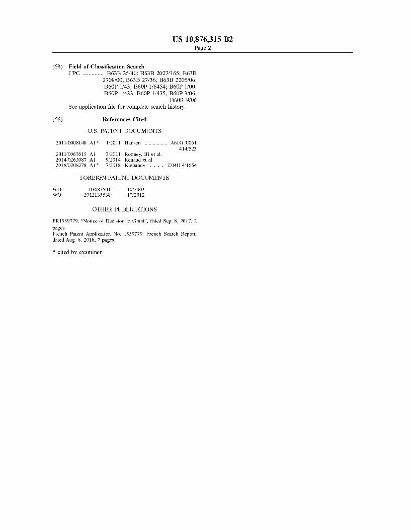
lii(i I illustrates a vieiv in perspective of a swinuningpool clemiing device accordiim to the prior art:
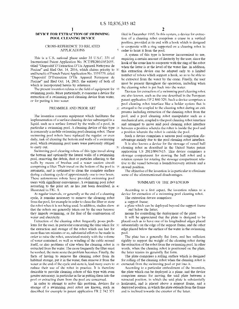
FICi 2 is a highly schematised side viev of the elementsof the device. including a cleanin mbot. the latter beingplaced ln the sivinunin pool„
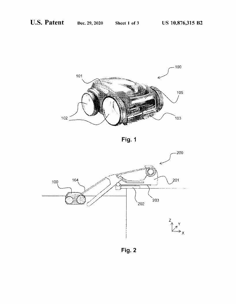
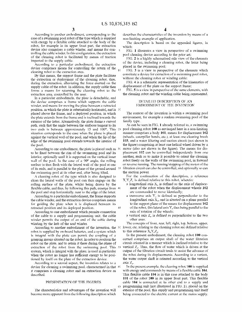
FICi 3 is a view in pcrspectivc of lhe clcmcnts wluchconstitute a device lor extraction ol a swimming pool roboLv ithout the cleaning robot or wutding cable;
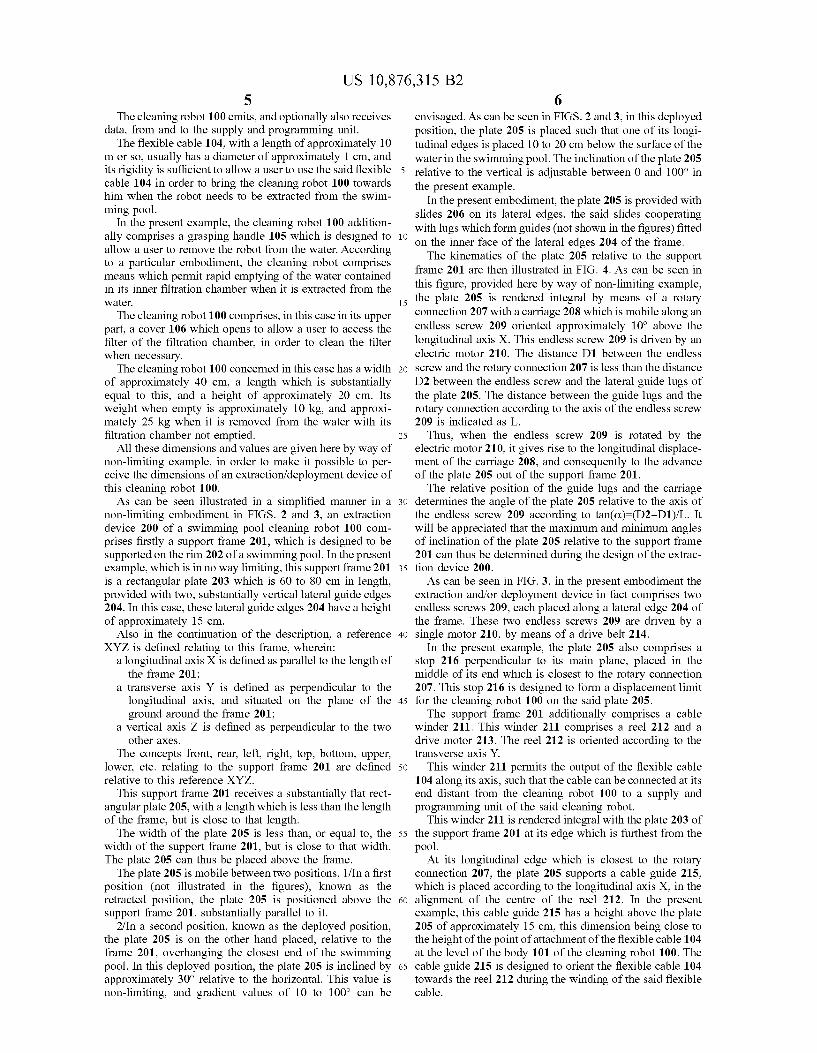
lil(i 4 is a schematic representation of the kinematics ofdisplacement of the pLate on the support fmsme,
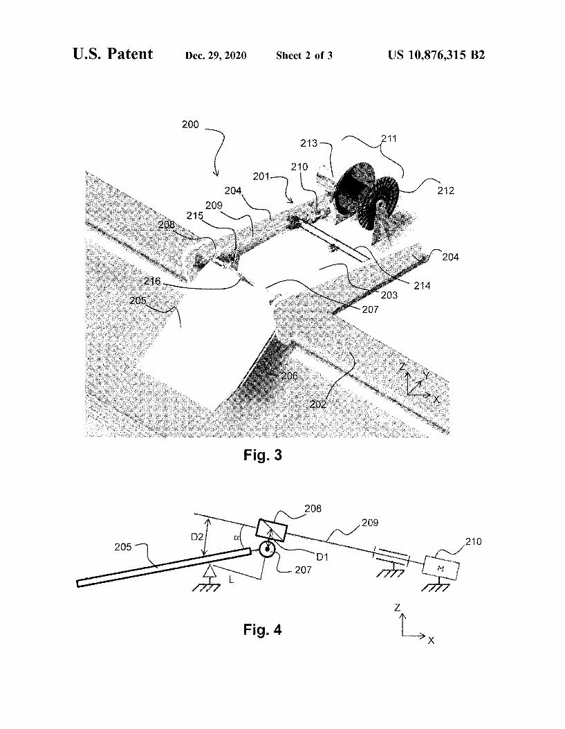
FICi. 5 is a viev, in perspective of the same elements. withthe cleaning robot and the winding cable being represented.
Dl!TAII,I ID DIIS('RIHI ION Ol'NEMBODIMENT OF THE INVENTION
Thc context ol'hc ulvcnlion is witlun n swunmulg poolenvironment, for cxmnplc a sunken swinuning pool of Ihefamily type.
As can be seen in li ICi. 1 already referred to, a swinuningpool cleaning mbot I UU as envisaged here in a non-limitingmanner comprises a body 101„means for displacement 102(wheels. caterpillar bands. etc.), at least one cleaning brush103, and a water lilicnng and suction circuit fltot shown inthc Iigurc) compnsing al least one hchcal wheel driven by amotor (also not shown in the figure) 'lhe means for dis-placenient 102 can be contmlled independently from oneamither, such as to make it possible to onent the cleaning,mbot freely on the wafls of the swinmting pooL in fotwardor reverse Ituufing. The running/stopput of the motor of theliltrauon circuit can also bc conlroflixl, aud opuoually so cmilhc suction power.
For Ihc continuation ol'hc dcscuption, a rcfcrcnceX„Y,/„ is defined relative lo this robot, ivherem
a longitudinal axis X„ is defined as the axis of displace-ment of the robot when the displacement wheels 102are commanded to move identically:
a lransvcrse axis Y,. Is delincd as perpendicular lo thclongitudinal axis X,. Bnd is siluatixl on a plmie parallelto Ihc support plane of thc nu:dns lbr disphmemcnt 102of the robot, this lateral axis Y,.thus being parallel to theaxis of rotation of the ivheels;
a vertical axis Z, is defined as perpendicular to the twoother axes.
Thc concepts of lbonl. rear. Iefi. righL top, bottom. upper,lowcn cic. Iclallilg 10 lhc cicinllllg I'obol drc dclincd rcldlivcto tlus relbrencc X,Y,Z,.
In the present embodiment, the cleanmg robot 100 con-cerned coinprises an output shaft of the water filtrationcircuit oriented in a manner which is inclined relative to thevertical 7„. Thus. the flow of water which is driven at theoulpul of Ihc lillrauon circuit lends to assist the advance ofthc robot durulg ils displaccmenls Accorihng lo a varianLthc wiilcl olllpilt shdfl ls orli Bled Bccordlng 10 lhcvcllicdlalxls /
In the present exaniple, the cleaning robot IUU is suppliedv ith energy and conunands by means of a flexible cable 104.This flexible cable 104 is in this case attached to the body101 of thc robot 100 ul iis upper front part This flcxiblecable 104 is connixled at ils other cnd to a supply andprogranuning unit fltot illustrated ut FIG. 1), phmed on Iheexterior of the pool, this supply and prograntming unit itselfbemg connected to the electric current at the niains supply
US 10,876,315 B2i
lhc cleanuig robot 100 enuts, and opuonally also receivesdata. fmm and to the supply and progranuning tuiit
'lite tlexible cable 104. with a length of approximately 10m or so, usually has a diameter of approximately I cm, andits rigidity is sufficient to allov. a user to use the said flexiblecable 104 in order to bring the cleaning robot 100 towardslum when thc robot needs to bc cxtractcti lbom the swim-Ilillig piiol.
In the present example. the cleaning robot 100 addition-ally comprises a grasping handle 105 which is designed to io
alloiv a user to remove the robot from the water Accordiagto a particular embodiment, the cleaning robot comprisesmeans which permit rapid emptying of the water containedin its inner liltration clrambcr when it is cxtractcti from thcwatt:i; 1
'lite cleaning robot I UO comprises. in this case in its upperpart, a cover 106 winch opens to allow a user to access thefilter of the filtration chaniber, in order to clean the niterwhen necessary.
The cleaning mbot 100 concerned in this case has a width zo
ol'pproximately 40 cm, a length wluch is substantiallyequal to this, and a height of approxinuitely 20 cm. Itswei ht when empty is approximately 10 kg, and approxi-niately 25 kg when it is removed from the water ivith itsfiltration chamber not entptied
All these dimensions and values are given here by w:ay ofnon-liniiting example. in order to make it possible to per-ceive the duneusions ol'n extraction/deployment device ofthis cleamng robot 100.
As can be seen illustrated in a simplified manner in a ionon-limiting entbodiment in Iil(iS. 2 and 3„an extractiondevice 200 of a swimniing pool cleaning robot l(kfl cont-prises firstly a support fmme 201, which is designed to besupported on the rim 202 of a swimming pool. In the presentcx unple, which is in uo way linuting. Ons support frmne 201 isis a rectangular plate 203 wluch is 60 to 80 cm ui len th,provided with two, substantially vcr(ical lateral guide edges204 In this case. these lateral guide edges 204 have a heightof approximately 15 cni
Also in the continuation of the description, a reference soXYZ is defined relating to this fmme. wherein;
a longitudutal axis X i ~ dclined as parallel to thc length ofthc Irtunc 201,
a transvcrsc axis Y is delincd as pcrpcnthcular to thcion itudinal axis, and situated on the plane of the
mund around the fmnie 201;a vertical axis Z is defined as perpendicular to the tv o
other axes.lite concepts front, rear. left, right, (op, bottom, upper,
lower, etc. relating to thesupport frame 201 arc delincd o
relative to tlus rcfi:rcnce XYZ.1his support frame 201 receives a substantially flat rect-
angular plate 205, with a length which is less than the lengthof the franie, but is close to that length.
The width of the pLate 205 is less than, or equal to. the sswidth of thc support Iramc 201, but is close to that width.Thc plate 205 can tlnis be placed above the liame.
lhc plate 205 is mobile bc(ween two positions. I/In a Iirs(position (not illustrated in the figures), known as theretracted position, the plate 2(kg is positioned above the ri!
support frame 201. substantially parallel to it.2/In a second position, known as the deployed position,
thc plate 205 is on the other hand placed, relative to theframe 201, ovcrhangutg the closest end of the swmuningpool. In this dcploycd post(ion. (hc plate 205 is uiclincd by ssapproxinmtely 30" relative to the horizontal. 'I'his value isnon-limiting, and gradient values of 10 to 100" can be
mtvisagcd. As ctm bc scen ui FIGS. 2 and 3, in flus deployedposition. the plate 205 is placed such that one of its longi-tudinal edges is placed 10 to 20 cm below thc surface of thev ster in the sivinimina pool. 'lite inclination of the plate 205rclativc to the vertical is adlustable bctwccn 0 and 100" inthe present example
In the present embodiment, the plate 205 is provided withslides Z06 on its lateral edges, the said slides coopemting,with lugs vvlflch form guides (not show n in the figures) fittedou thc inner Ibcc ol'hc lateral edges 204 of the frame.
The kinematics of the plate 205 reLative to the supportframe 201 arc then dlustrated in FIG. 4 As can bc semi intlus figure. provided here by way of non-lintiting example,the plate 205 is rcndcrcd integral by means of a rotaryciilulectloll 207 v, ith a carriage 208 which is mobile alono anendless screw Z09 oriented approximately 10" above thelongitudinal axis X 'Ibis endless screw 209 is driven by anelectuc motor 210. The distance DI between the endlessscrew and the rotary connection 207 is less than thc distanceDZ between the endless screw and the lateml guide lu s ofthe plate 205. Thc die(mice beta can thc gunle lugs mid therotary connection according to the axis of the endless screiv209 is indicated as I,.
I'hus, when the endless screw 209 is rotated by theelectnc motor ZIO. it ives rise to the longitudinal displace-ment of the carriage 208, and consequently to the advanceof thc plate 205 out of thc support frame 201.
Thc rclativc posiuon of thc guide lugs and the carrie cdeternnnes the angle of the plate 205 relative to the axis ofthe endless screw 2U9 according to tan(et) (D2 — Dl)/I,. Itv ill be appreciated tliat the maximum and minimum anglesof inclination of the plate 205 relative to the support Ibame201 can thus be determined durin the design of the extmc-tion dcvicc 200.
As can bc scen in FIG. 3. ui the prcscut embodiment theextraction midior deployment device in fact composes twoendless screws 209, each placed along a lateml edge 204 ofthe frame. 'I'hese two endless screws 209 are driven by asin le motor 210. by means of a dnve belt 214
In the present example, the plate 205 also comprises astop 216 pcrpcndicular to its main plane, placed ui thcmiddle of its cnd which is closest to the rotary connection207 This stop 216 is designcii to fomi a displacement lumtfor the cleaning robot 100 on the said plate 205
'I'he support fmme 201 additionally coniprises a cablev inder 211. Tlus winder 211 comprises a reel 212 and adrive motor Z13. The reel 212 is onented according to thetransvcrsc axis Y.
This winder 211 pcrnuts thc output of the flcxiblc cable104 along its axis, such that the cable cau be conniwtcd at itsend distant from the cleaning robot 1(NI to a supply andpmgramming unit of the said cleaning robot
This v, inder ZII is rendered in(egal with the plate 203 ofthe support frame 201 at its edge which is furthest from thepool.
At its longituduial cdgc wluch is closest to thc mtaryconniwtion 207, thc plate 205 supports a cable guide 215.v hich is placed accordion to the longitudinal axis X. in thealignment of the centre of the reel 212 In the presentexample. tlfls cable uide 215 has a hei ht above the plate205 of approximately 15 cm. this dimension being close tothe height ol'hc pout( ol'attachment of the flcxible cubic 104at thc lcvcl of the body 101 ol'hc cleaning robot 100. Thecable guxlc 215 is dcsignixi to oncnt the flcxiblc cable 104towards the reel 212 during the v inding of the said flexiblecable.
US 10,876,315 B2
11&c cxtrac&ion dcv&cc 200 also comprises mem&s forcontrolling the drive n&otor 210 of the endless screv s 209and the winder 211
'll&e dimensions and choice of materials which constitutethe various elements prev&ously described are detem&ined bythe forces to be absorbed. and by the conditions of thesw immu&g pool cnviro&uncn(.Opcrafing Mode
1'he ex&rection of the robot can be triggered either auto-n&atically at the end of the cleaning cycle, or manually by the &0
user by ac&ion on the supply and control unit of the extrac-I&on svs ten&.
The supply and contml unit of the extraction system &s
co&uux&ed to thc supply and progrim&ming unit of Ihe robot,so tha& the motors of thc extraction system;md Ihc motors of &
the robot are controlled in a coordinated &nanner.Accordin to a parncular embodiment, the supply and
control uni& of the extract&on system and the supply andprogranuuing un&t of the robot are combined.
When a swinuuin pool cleaning robot 100 must be &0
cxtracicd from thc pool, Ihe ex(rection pmccss composes thefollowu&g steps
If the pla&e 205 is not initially in the deployed position,with its outer edge submerged by approximately 10 cm or so,the systen& conuuands &ts deployment by starting up themotor 210 &ihich drives the endless screws 209.
Then„ the winder 211 is started up, and starts to wind theflcx&blc cable 104 wh&ch &s co&u&cc&ed to the cleaning robo(100 on(o the reel 212. The mbot 100 is tlnis brou h(pmgressively &n the direction of the plate 205, with its front 10
face oriented in the direction of the plateWhen the robot 100 reaches the immediate vicinity of the
plate 205. its wheels 102 are supported on the plate. and therobot advances by itself, or &s drawn by the flexible cable104 wh&ch &s bcu&g wound, uunl 0 is totally supported on the &i
smd pla&c. It &s blocked against Ihe stop 216 ol thc said plate205.
At this moment, the wheels 102 of the rolx&t are stopped(if its n&ovement was still heing conunanded)
The situation is then that in FIO. 5. 00
Then„ the motor 210 which drives the endless screws 209&s s(aricd up, such as to rc(uru thc plate 205 u&to Ihc suppor(frame 201 Dunng tlus time, thc wu&dcr 211 mmnta&nstension on the Ibex&blc cubic such as to rc&ain Ihe robo( 100on the plate 205
At the same time. if the cleaning robot 100 is prov&dedwith a mpid emptying device. the latter is activated in orderto reduce the weight of the water in the filtration chamber,and thus fl&e Ibrccs exerted on the plate by Ihc endless screw s209. 0
When Ihc pkl(c &s con&pic&clv rc'ndcu:d w&thu& Ihc fran&c201. the n&otors of the endless acre&vs 209 and the winder211 are stopped 'I'he robot is then avaiLsble for handliag bythe user. for example for cleanin of the filter. or simply toren&ain thus in the storage position before a fnture use. 1.
Bccausc of thc mob&l&(y ol'hc plate m&d its rctr mtion insideIhe dcv&ce, Ih&s storage pos&l&on clears thc extract&on dev&ccas well as Ihc clca&ung robot from thc pool, withou! activeinterven&ion by the user I'hus, the user can have all the spaceavailable for swimming, whilst reducing the risks of injury iocaused by the presence of submerged elements.
Particularly advanta eously. the time for extraction of therobo( is relatively shor(, & e. advanui cously 5 mimi(ca orless. Snd prcfi:rably 2 minutes or less, (hc user fl&us beingable to have thc pool ava&lablc for swimnnng very quickly. Si
1'he pmcedure for putting the cleaning robot into thewater is exactly the inverse of what has just been descubed,
and it w&11 bc appriuiatcd Ihal the cxtracuon dcv&cc also aclsas a device for putting into the water
'I'he invention c)aimed is:I An extraction system comprising:a. a svvinunin pool cleanin robot:b a suppor( friune supponcd on a um of a swinunu&g
pool;c a first plate conhgured for movement benveen a
retracted position outside of the swimming pool and a
deployed position (i) beyond and below the supportframe and (ii) extending into the swinm&ing pool;
d a flexible power cable electncally connected betweenthc sw&mmu&g pool cleaning robot and 0 supply ofelcctucity,
e. means for winding the tlexible power cable: andf n&cans for guiding the first plate as it moves between the
retracted position and the deployed position.2 An extraction system according to cLaim I in wlfich (0)
the support frame comprises a second plate and (b) themeans lor guiding Ihe first plate compnscs la(eral guuleedges of thc scconil pl&i&c.
3 An extraction sys&em according to claim I in which thefirst plate (a) is substantially honvontal and above thesupport fra&ne ivhen in the retracted position
4 An extraction system according to claim I in which thefirst plate is detachable from the support frame.
5 An extract&on sy's&cni con&pfish&g.a. a sw&nun&ng pool cleaning robot:b a support fran&e supported on a un& of a swimming,
poohc. a first plate;d means fi&r moving the first pLate betv een a retmcted
position outside of the swinm&ing pool and a deployedposi(ion (i) beyond and below thc support frame and(n) extend&ng u&to thc suinuniug pool.
c. a flcxiblc cubic coru&ected Io thc sw&mnung poolcleaning &Obo; and
f means for ivindin the flexible cable onto a reel.6 An extraction system according to claim 5 in which the
means for moving the first plate comprisesa. an cku(rm motor,b m& cndlcss screw driven by thc electric mo&or: m&d
c. a ro(ary coru&ccuon w &Ih a camagc Ihat &s mob&le alongthe endless screw.
7 An extraction systen& according to claim 6 &n which theelectnc motor drives the endless screw via a drive belt.
8 An extraction system accord&ng to claim 6 furthercomprising means I'or gu&ding thc Iirs& pla&c as &I movesbc(wiun thc rc&ractcd posiuon m&d thc dcploycd posiuon.
9 An extract&on sys&cm according to claun 8 u& wiuch (0)the support fmme comprises a second plate and (b) themeans for guiding the hrst plate comprises lateral guideedges of the second plate.
10. An extraction system according to claim 1 in wlfichthc Iirs( plate, when u& Ihc re(me(cd pos&t&on, &s above andsubstan(ially parallel Io Ihc support frame.
11. An cxtracuon system accordu&g to clmm I in wiuchthe hrst plate con&prises an outer edge which extends into theswin&nnng pool when the first plate is in the deployedposit&on.
12. An extraction system according to claim 1 in whichthe means fi&r w&nd&ng the flexiblc power cable comprises acable winder supported by the support I'rame.
13. An cx(itic(ion sv'stcn& ilcciirihng Io el&I&n& 5 &n wh&chthe means for winding the tlexible cable composes a cablewinder supported by the support fm&ue
US 10,876,315 B210
14. An extraction system according io clmm 1 ul wluch aninclination of the tirst plate in the deployed position extend-ing ulto thc swimnuug pool m adluslable relallvc lo a verticalplane.
15. An extraction system according io clmm 5 ul wluch aninclination of the first plate in the deployed position extend-in into the slvimmin pool is adjustable relative to a verticalplane.
16. An extmsction system according to claim 1 in which111
thc means for winding thc flexiblc power cable (a) defines a
rotation axis and (b) permits output of the flexible powercable along the rotation axis lhr electrical connection to thcsupply of electucity
1 7. An extraction system accordulg to clmm 5 ul whichthe flexible cable is a flexible pov:er cable and the means forlvinding the flexible cable (a) defines a rotation axis and (b)pernlits output of the flexible cable along the rotation axisfor electrical connection to a supply of electricity.
18. An cxtracuon system compnsulg. ioa. a swimming pool cleaning nlbot;b a support frame supported on a rim of a slvimnling
pool;
c. a first plate configurkxl fiir movcmcnt betweenrctractcd position and a dkpfoycd position (I) beyondand belolv the support frame and (il) extending into theslvlnunin pool;
d a flexible cable connected to the swlmnling poolcleaning mbot:
c. means for wuldulg thc flcxlblc cable, andf ntcluls fol golding Ihc first plate Ils lt nlovcs bctw con thc
retracted position and the deployed position.19. A device for extracting a cleanin robot from a
sw ilunung pool colrlpnslng ao intel'lol'ont'uiullg watcl'nda um abol e a surface of the contained w ater, comprising:
a. a support frame supported by the rim;b a first plate conligured for movement bctwccn
rctractcd posluon above thc surface of Ihc contatnkxfwater and a dk7Iloyksf position cxtcndulg ulto thc inie-rior belolv the surface of the contained water:
c a flexible cable connected to the swlmnling poolcleaning robot;
d means for lvinding the flexible cablet ande. means for guidin the first plate as it moves between the
retracted posluon and the dk7I)oykxf position.


![(12) United States Patent Hanneman et a]. Dec. 17, 2013./ghannema/Patent-8612205.pdf · US008612205B2 (12) United States Patent Hanneman et a]. US 8,612,205 B2 Dec. 17, 2013 (10)](https://img.dokumen.tips/doc/110x75/6018aa91f9e32a2034373f8d/12-united-states-patent-hanneman-et-a-dec-17-ghannemapatent-8612205pdf.jpg)