Embed Size (px)
Citation preview
111111111111111111111111111111111111111111111111111111111111111111111111111US009829358B2
(12) United States PatentMu et al.
(10) Patent No.:(45) Date of Patent:
US 9,829,358 B2Nov. 28, 2017
(54) DEVICE FOR DETERMINING A PROPERTYOF A FLUID AND METHOD OF FORMINGTHE SAME
(58) Field of Classification SearchNoneSee application file for complete search history.
(71) Applicant: Agency for Science, Technology andResearch, Singapore (SG)
(56) References Cited
U.S. PATENT DOCUMENTS
FOREIGN PATENT DOCUMENTS
(72) Inventors: Xiaojing Mu, Singapore (SG);Chengliang Sun, Singapore (SG); AlexYuandong Gu, Singapore (SG)
(73) Assignee: Agency for Science, Technology andResearch, Singapore (SG)
5,223,763 A6,011,346 A
6/1993 Chang1/2000 Buchallall et al.
(Continued)
( *) Notice: Subject to any disclaimer, the term of thispatent is extended or adjusted under 35U.S.c. 154(b) by 0 days.
EPEPWO
2399676 Al2065228 Bl
W02012081008 Al
12/20114/20136/2012
(21) Appl. No.:
(22) PCT Filed:
(86) PCT No.:
15/031,982
Nov. 21, 2014
PCT/SG2014/000553
OTHER PUBLICATIONS
Elfrink, et aI., Shock Induced Energy Harvesting with a MEMS
Harvester for Automotive Applications, IEEE IEDMl1-677 29.51(2011).
§ 371 (c)(1),(2) Date: Apr. 25, 2016
(87) PCT Pub. No.: W02015/076757
PCT Pub. Date: May 28, 2015
(Continued)
Primary Examiner - Harshad R Patel(74) Attorney, Agent, or Firm - K. David Crockett, Esq.;Paul J. Backofen, Esq.; Crockett & Crockett, PC
(65) Prior Publication Data (57) ABSTRACT
(2006.01)(2006.01)
(Continued)
(30) Foreign Application Priority Data
(52) U.S. Cl.CPC GOlF 1/3218 (2013.01); GOlF 1/3209
(2013.01); GOlF 1/36 (2013.01);(Continued) 20 Claims, 19 Drawing Sheets
In various embodiments, a device for determining a propertyof a fluid may be provided. The device may include a fluidreceiving structure configured to receive the fluid having afirst condition. The device may further include a flow controlstructure coupled to the fluid receiving structure. The flowcontrol structure may be configured to change the firstcondition of the fluid to a second condition. The device mayfurther include a determination mechanism configured todetermine the property of the fluid based on the secondcondition. The device may also include a voltage generationmechanism a voltage generation mechanism configured togenerate a voltage based on the second condition.
Sep. 22, 2016US 2016/0273947 Al
Nov. 22, 2013 (SG) SG201308684-8
(51) Int. Cl.GOlF 15/06GOlF 1/48
512b
r-F 5128
DD~ V1:forenergyharvesting¥ V2:forflowratemonitoring~ -----. Flowtrace
Vi V2
~y5148 514b
504~~-===
502
US 9,829,358 B2Page 2
OTHER PUBLICATIONS
(51)
(52)
Int. Cl.GOlF 1/32GOlF 1/36H02N 2/18U.S. Cl.CPC .
(2006.01)(2006.01)(2006.01)
GOlF 1/48 (2013.01); GOlF 15/063(2013.01); H02N 2/185 (2013.01)
7,986,051 B28,314,503 B2
2003/0034900 Al2005/0134047 Al2009/0134632 Al2009/0189778 Al
7/2011 Frayne11/2012 Liu et al.2/2003 Han6/2005 Schumacher et al.5/2009 Kvisteroy et al.7/2009 Juan et al.
References Cited
u.s. PATENT DOCUMENTS
(56)
6,424,079 Bl7,199,480 B27,208,845 B27,310,052 B27,400,264 B27,560,856 B2
7/2002 Carroll4/2007 Fripp et al.4/2007 Masters et al.
12/2007 Bowman7/2008 Boaz7/2009 Chen et al.
Sun, et aI., PVDF Microbelts for Harvesting Energy from Respiration, 4 Energy and Environmental Science 4508 (2011).Aktakka, et aI., Thinned-PZT on SOl Process and Design Optimization for Piezoelectric Inertial Energy Harvesting, Transducers1649 (Jun. 2011).Elfrink, et aI., Vacuum-Packaged Piezoelectric Vibration EnergyHarvesters: Damping Contributions and Autonomy for a WirelessSensor System, 20 Journal of Micromechanics and Microengineering 1 (Sep. 2010).
u.s. Patent Nov. 28, 2017 Sheet 1 of 19 US 9,829,358 B2
N__ 0
~
II
II
I
u.s. Patent Nov. 28, 2017
FIG. 2
Sheet 2 of 19 US 9,829,358 B2
200
202
206
204
208
302
airflow V )B
Bluff body{,'-- .~
304
FIG. 3
tReceiving Transducer
Transmitting Transducer
300
e•7J).•~~~
~=~zo~N~CfO
No..........:J
rFJ
=('D('D.....tH
o........\0
drJl
,,'CQON'CWtitQO
=N
u.s. Patent Nov. 28, 2017 Sheet 4 of 19 US 9,829,358 B2
No~
u.s. Patent Nov. 28, 2017 Sheet 5 of 19 US 9,829,358 B2
FIG. SA
500a
512b
Laminarflow unitPi L P \ A2 nP=P1-P2...--------+-fI!' I
I
\Nhistlecavity
504 ----------l!itl
502
IFDD
J
514a
512aV1: for energy harvestingV2: for flow rate monitoring
-------~ Flow trace
+ Whistle cavity type EHs
u.s. Patent
60
50
'>E 40.....::J
.s- 30::Joe:uC) 20C'I:I......
~ 10
o
Nov. 28, 2017 Sheet 6 of 19
FIG.5B
US 9,829,358 B2
500b
o 1 2 3 4 5 6
Input air pressure llP (psi)
u.s. Patent Nov. 28, 2017 Sheet 7 of 19 US 9,829,358 B2
coCO
~'r""
0 (00(0 CO
N'r""(0
CON'r""(0
CO~'r""(0
CON'r""(0
CO< ~\0 'r""
d (0
~
~
CO~'r""(0
u.s. Patent Nov. 28, 2017 Sheet 8 of 19
FIG,6B
US 9,829,358 B2
600b
604b
614b
612b
FIG.6C
600c
612c 612c
u.s. Patent Nov. 28, 2017 Sheet 9 of 19
FIG. 7
US 9,829,358 B2
702
.-' PI h
\
728
722 724
cavity
828
804
Narrow
832834
FIG. 8
RF module(transmitter)
838b
Antenna
Power line" (po,ver supply to pmcesser and
832
~1EMSEH module
Super capacitor 830
800
838a
e•7J).•~~~
~=~zo~N~CfO
No..........:J
rFJ
=('D('D.........oo........\0
drJl
,,'CQON'CWtitQO
=N
940
934
930
Gas flo\v rate nleasurenlellt lliO
FIG. 9
938a
900
938b
e•7J).•~~~
~=~zo~N~CfO
No..........:J
rFJ
=('D('D.............o........\0
drJl
,,'CQON'CWtitQO
=N
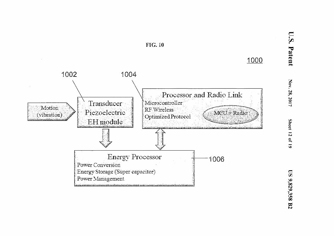
FIG. to
1000
e•7J).•~~~
~=~zo~N~CfO
No..........:J
rFJ
=('D('D.........N
o........\0
undRudio Link
1004
TransducerPiezoelectricEHnlodule
1002
Energv Processor"'"',~'
Pov,rer ConversionEnergy Storage (Super capacitor)Povver 1\-1anagement
I 1006
drJl
,,'CQON'CWtitQO
=N
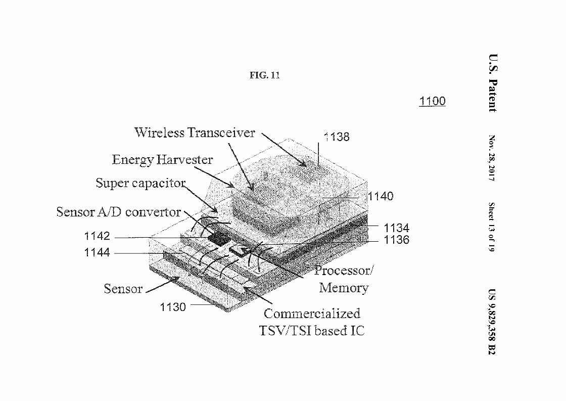
FIG. 11
1100
e•7J).•~~~
~=~\\.7ireless Transceiver
Ener!!V' Harvesterc"....
Super capacito"'''
Sensor A/"D convertor
1142::
1144 -------i
Sensor
1130
1138
rocessorit
lvlenlor'lr'
C:onnnercializedTS\T./"TSI based IC·
11341136
zo~N~CfO
No..........:J
rFJ
=('D('D.........(.H
o........\0
drJl
..:...cQON...cWUtQO
=N
u.s. Patent Nov. 28, 2017 Sheet 14 of 19 US 9,829,358 B2
1240a
FIG.12A
1240c
1200a
1240b
u.s. Patent Nov. 28, 2017 Sheet 15 of 19 US 9,829,358 B2
FIG.12B
1200b
1202b. The channel
0.4 0.6Time (ms)
0.04
0.02
0.00
..Q.02
..0.04~.......e.......--.L .............~.........Lo_~~~ .............~~..............J
0.0
u.s. Patent Nov. 28, 2017 Sheet 16 of 19 US 9,829,358 B2
FIG.12C
1200c
- The channel AK.Hz)
me""' The channel BKHz,
... (22.66 KHz)
,., (11
~o
",80
00 1-,'~~.J..-,.-.d-l~
,,40
,,60
,,80
,,1001204b
,,20
~o·
,,·GO
,,80
-The channel C"!l
(22 •.8KHz)
20 30Frequency ~.kH
u.s. Patent Nov. 28, 2017 Sheet 17 of 19 US 9,829,358 B2
1302a
FIG.13A
1300a
u.s. Patent Nov. 28, 2017 Sheet 18 of 19 US 9,829,358 B2
...QooC")~
u.s. Patent Nov. 28, 2017 Sheet 19 of 19 US 9,829,358 B2
FIG. 14
provide a fluid receiving structureconfigured to receive the fluidhaving a first condition
1400
'\ 1402
couple a flow control structure tothe fluid receiving structure, theflow control structure configured tochange the first condition of thefluid to a second condition '\
'\ 1404
provide a determination mechanismconfigured to determine theproperty of the fluid based on thefluid having the second concijtion
\ 1406
provide a voltage generationmechanism configured to generatea voltage based on the fluid havingthe second condition \
\ 1408
US 9,829,358 B2
Various aspects of this disclosure relate to devices fordetermining properties ofa fluid and methods of forming the 15
devices.
2
DETAILED DESCRIPTION
The following detailed description refers to the accompanying drawings that show, by way of illustration, specificdetails and embodiments in which the invention may bepracticed.
The word "exemplary" is used herein to mean "serving as60 an example, instance, or illustration". Any embodiment or
design described herein as "exemplary" is not necessarily tobe construed as preferred or advantageous over otherembodiments or designs.
It should be understood that the terms "on", "over", "top",65 "bottom", "down", "side", "back", "left", "right", "front",
"lateral", "side", "up", "down" etc., when used in thefollowing description are used for convenience and to aid
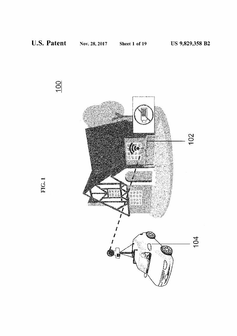
FIG. 1 is a schematic illustrating a wireless remote meterreading process according to various embodiments.
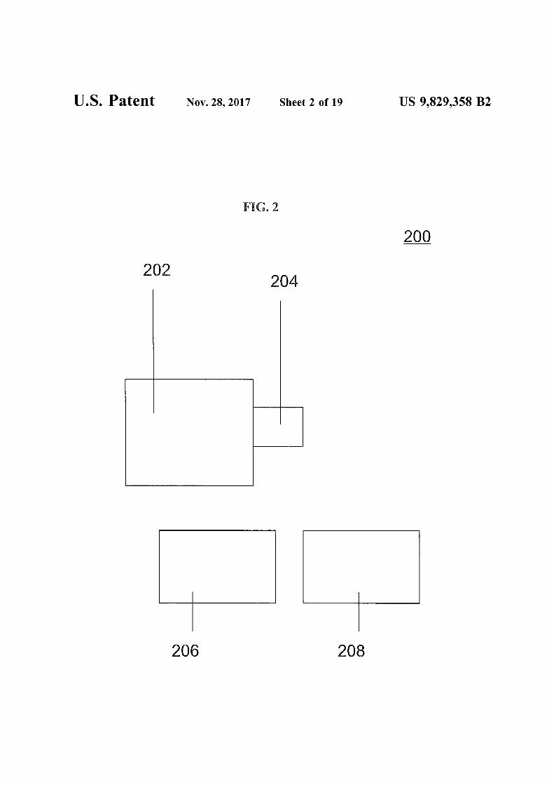
FIG. 2 is a schematic illustrating a device for determininga property of a fluid according to various embodiments.
FIG. 3 is a schematic of a device for determining aproperty of a fluid according to various embodiments.
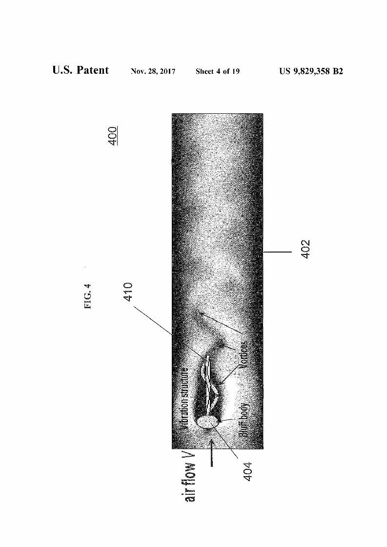
FIG. 4 is a schematic of a device for determining aproperty of a fluid according to various embodiments.
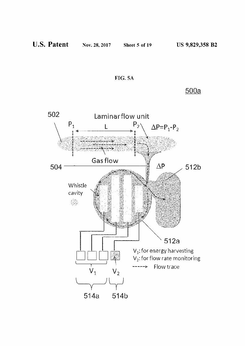
FIG. SA is a schematic of a device for determining a10 property of a fluid according to various embodiments.
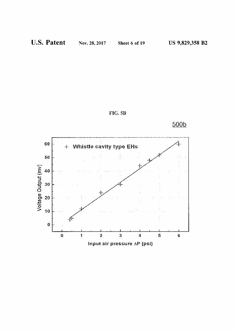
FIG. 5B is a plot of voltage output (in mV) against inputair pressure !J.P (in pounds per square inch or psi) illustratingthe linear relationship between open-circuit voltage outputand the input air pressure !J.P.
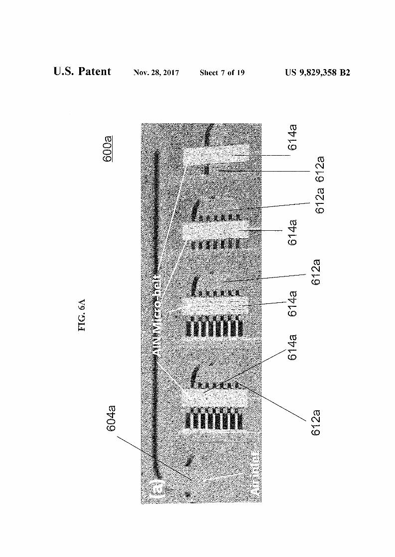
FIG. 6A is an optical image of a plurality of aluminumnitride micro-belt transducers within a cavity according tovarious embodiments.
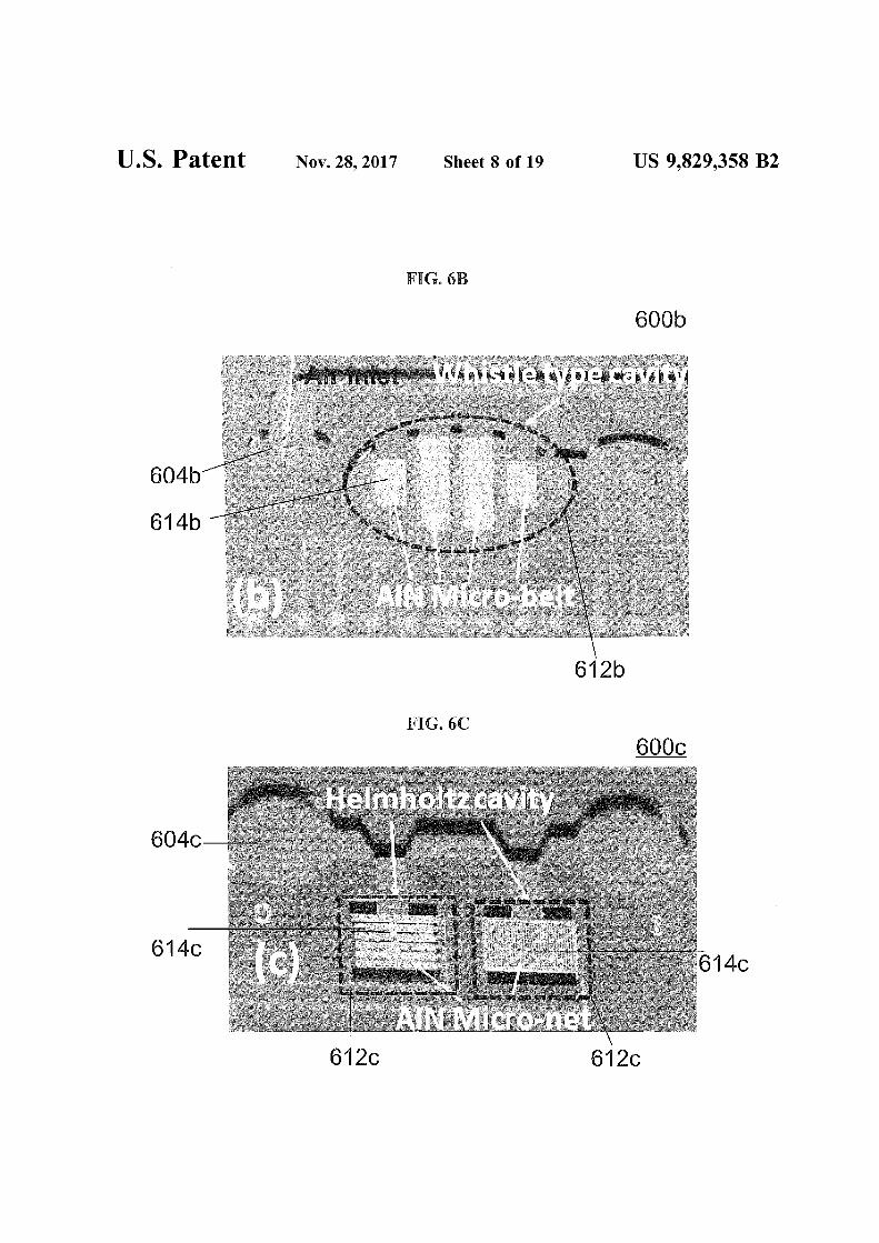
FIG. 6B is an optical image of a plurality of aluminumnitride micro-belt transducers within a cavity according to
20 various embodiments.FIG. 6C is an optical image of a plurality of aluminum
nitride micro-net transducers within a cavity according tovarious embodiments.
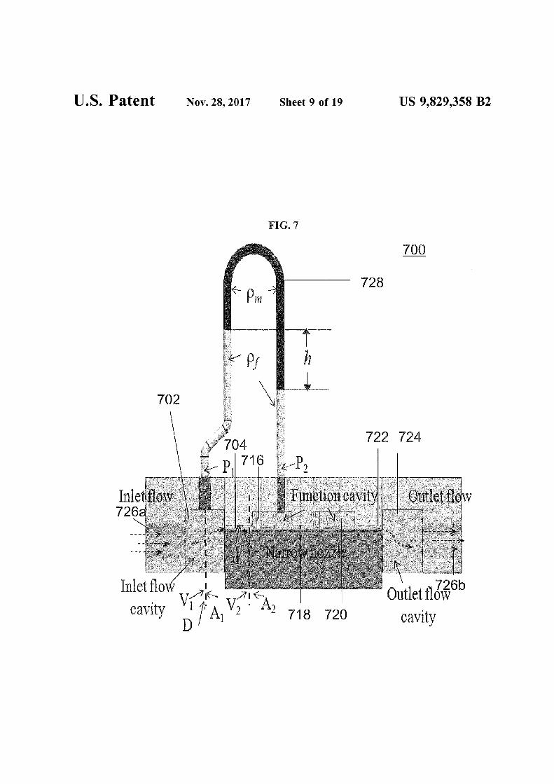
FIG. 7 is a schematic illustrating a device for determining25 a property of a fluid according to various embodiments.
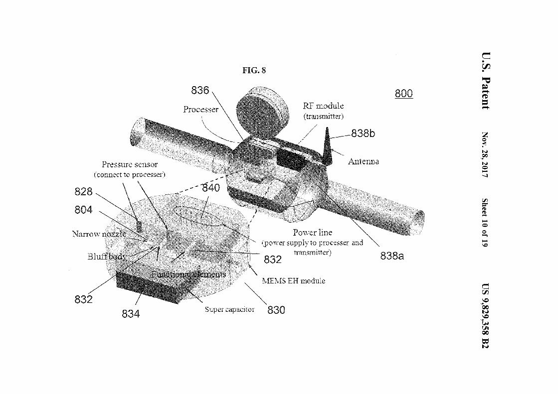
FIG. 8 is a schematic of a device for determining aproperty of a fluid according to various embodiments.
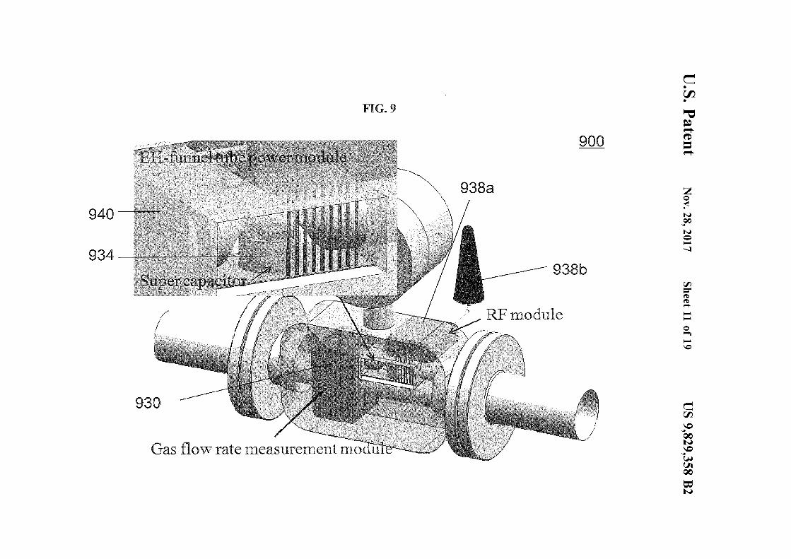
FIG. 9 is a schematic of a device for determining aproperty of a fluid according to various embodiments.
FIG. 10 is a schematic showing a system integrating theenergy harvesting module, the processor circuit and thetransmitter circuit according to various embodiments.
FIG. 11 is a schematic illustrating a wireless moduleaccording to various embodiments.
FIG. 12A shows a schematic showing a system includinga plurality of devices according to various embodiments.
FIG. 12B is a group of plots 1202a, 1202b, 1202c ofoutput voltages (volts) as a function of time (milliseconds orms).
FIG. 12C is a group of frequency spectra plots 1204a,1204b, 1204c of magnitudes (decibels of dB) as a functionof frequency (kilohertzs of kHz).
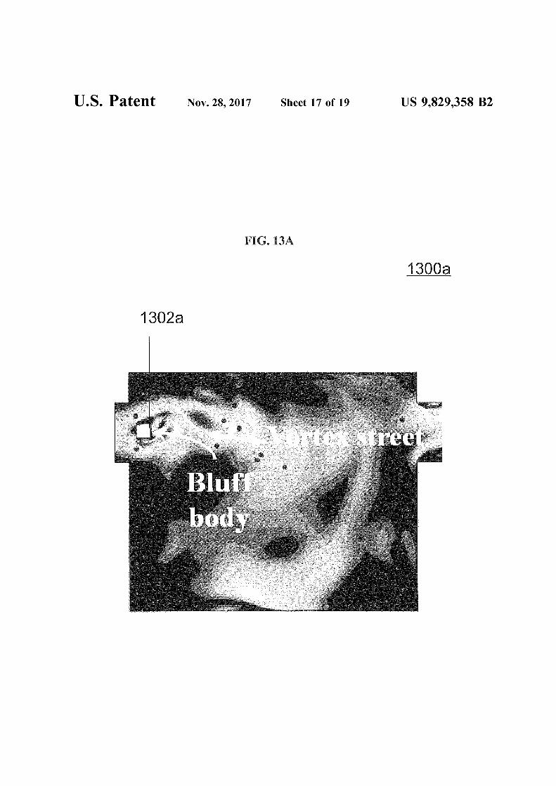
FIG. 13A is an image illustrating the simulated fluidbehaviour in a single cavity energy harvester according to
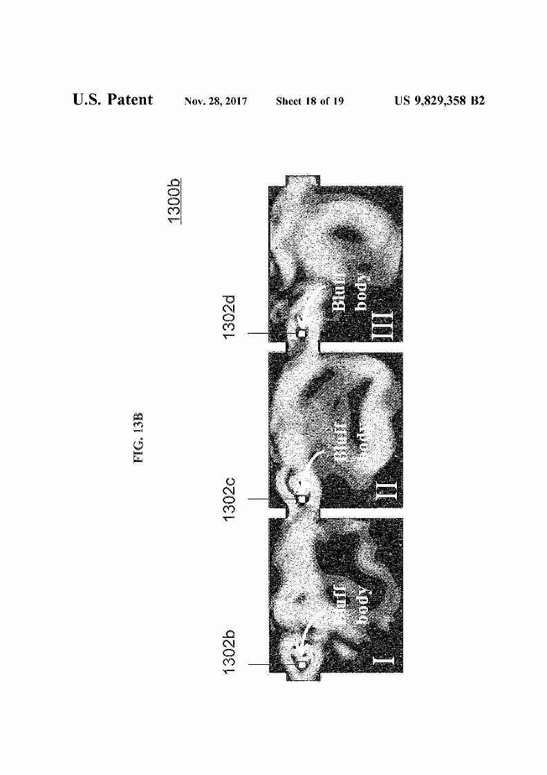
45 various embodiments.FIG. 13B is an image illustrating the simulated fluid
behaviour in a three-cavity energy harvester according tovarious embodiments.
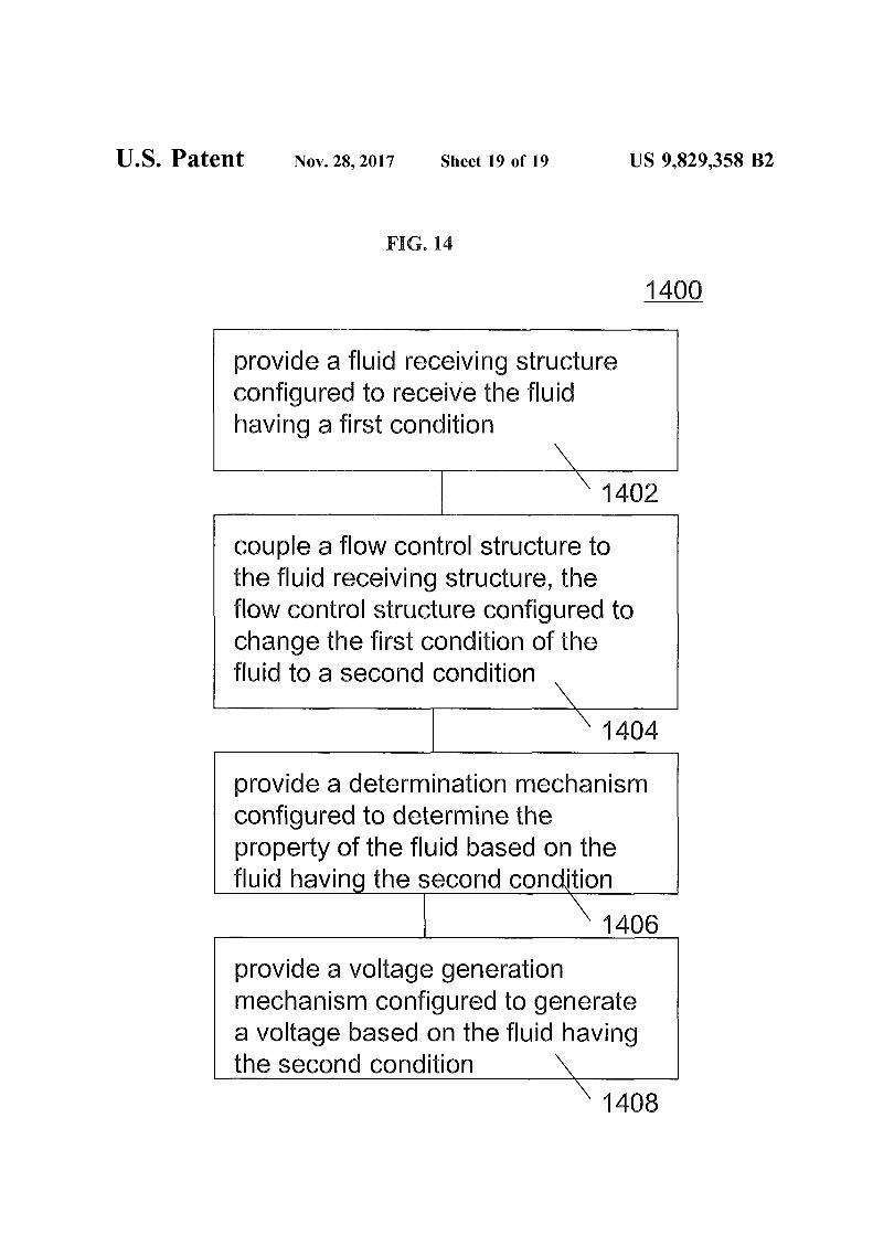
FIG. 14 is a schematic illustrating a method of forming a50 device for determining a property of a fluid according to
various embodiments.
35SUMMARY
BACKGROUND
TECHNICAL FIELD
CROSS-REFERENCE TO RELATEDAPPLICATION
BRIEF DESCRIPTION OF THE DRAWINGS
1DEVICE FOR DETERMINING A PROPERTYOF A FLUID AND METHOD OF FORMING
THE SAME
In various embodiments, a device for determining aproperty of a fluid may be provided. The device may includea fluid receiving structure configured to receive the fluidhaving a first condition. The device may further include a 40
flow control structure coupled to the fluid receiving structure. The flow control structure may be configured to changethe first condition of the fluid to a second condition. Thedevice may further include a determination mechanismconfigured to determine the property of the fluid based onthe second condition. The device may also include a voltagegeneration mechanism configured to generate a voltagebased on the second condition.
In various, a method of forming a device for determininga property of a fluid may be provided. The method mayinclude providing a fluid receiving structure configured toreceive the fluid having a first condition. The method mayfurther include coupling a flow control structure to the fluidreceiving structure, the flow control structure configured tochange the first condition of the fluid to a second condition.The method may additionally include providing a determi- 55
nation mechanism configured to determine the property ofthe fluid based on the fluid having the second condition. Themethod may further include providing a voltage generationmechanism configured to generate a voltage based on thefluid having the second condition.
The advantages of wireless automatic reading of gasmeters have long been recognized. Such advantages accruefrom the elimination of the high costs associated withmanually reading meters located a long distance from acentral utility office, inside of a customer's premises, atdangerous locations, and at the remote ends of a distributionnetwork. Furthermore, in rural utility networks, long distances are typically encountered between each meter location. Thus, more employees are required to manually readeach meter on a predetermined time schedule for accuratebilling. However, most traditional wireless modules requirea battery as a power source, and the battery may lead to 30
problems such as adding weight to the whole system, limitedlife time, high cost of replacement, or potential hazard to theenvironment.
This application claims the benefit of priority of Singapore patent application No. 201308684-8, filed 22 Nov.2013, the content of it being hereby incorporated by reference in its entirety for all purposes.
The invention will be better understood with reference tothe detailed description when considered in conjunction withthe non-limiting examples and the accompanying drawings,in which:
US 9,829,358 B23 4
ofthe gas, such as a flow rate of the gas, and which is at leastpartially powered by the gas flowing through, e.g. by thekinetic of the gas that flows through the gas meter. Variousembodiments may reduce the need or do not require a powersource such as a battery.
The voltage generation mechanism 208 may be configured to at least partially convert a kinetic energy of the fluidto electrical energy.
In various embodiments, a "circuit" may be understood as10 any kind of a logic implementing entity, which may be
special purpose circuitry or a processor executing softwarestored in a memory, firmware, or any combination thereof.Thus, in various embodiments, a "circuit" may be a hardwired logic circuit or a programmable logic circuit such as
15 a programmable processor, e.g. a microprocessor (e.g. aComplex Instruction Set Computer (CISC) processor or aReduced Instruction Set Computer (RISC) processor). A"circuit" may also be a processor executing software, e.g.any kind of computer program, e.g. a computer program
20 using a virtual machine code such as e.g. Java.In various embodiments, the flow control structure 204
may include or may be an obstruction within the fluidreceiving structure 202. The obstruction may be a bluffbody.The device may also include a vibration structure attached to
25 the obstruction. The vibration structure may also be referredto as a flexible structure.
The obstruction may be further configured to generate aplurality of vortex swirls in the fluid so that the fluid is thesecond condition. The obstruction may be configured to
30 alternately generate vortex swirls on a first side of theobstruction and a second side of the obstruction. Fluidflowing through the obstruction may be separated into twoportions, i.e. a first portion on the first side and a secondportion on the second side of the obstruction. The obstruc-
35 tion may be configured to create a local increase in pressure(and a local decrease in velocity) on the first portion and alocal decrease in pressure (and a local increase in velocity)on the second portion. Subsequently, the obstruction may beconfigured to create a local decrease in pressure (and a local
40 increase in velocity) on the first portion and a local increasein pressure (and a local decrease in velocity) on the secondportion.
The obstruction may be configured to generate periodicfluctuations of increased pressure and decreased pressure on
45 each side. When the first portion experiences an increasedpressure, the second portion may experience a decreasedpressure. When the first portion experiences a decreasedpressure, the second portion may experience an increasedpressure.
The vibration structure may be configured to move at afrequency due to the plurality of vortex swirls.
In various embodiments, the vibration structure mayinclude a transducer configured to detennine the property ofthe fluid based on the varying force. In various other
55 embodiments, the device may include a transducer configured to detennine the property of the fluid based on avarying force exerted by the plurality of vortex swirls. Inother words, the transducer may be included in the vibrationstructure or in another part of the device. A transducer may
60 also be referred to as a functional element.A transducer or transducers described herein may include
or be made of a suitable piezoelectric material such as butnot limited to aluminum nitride (AlN), zinc oxide (ZnO),lithium niobate (LiNb03 ), zirconate-titanate (PZT) or poly-
65 vinylidene fluoride (PVDF). The transducer or transducersmay also include a triboelectric material such as Kapton.The transducer or transducers may also include a magnetic
understanding of relative positions or directions, and notintended to limit the orientation of any device, or structureor any part of any device or structure.
To solve the abovementioned problems, battery-less selfpowered Energy Harvesting (EH) module for gas meterbuilt-in processor and RF module (transmitter and sensors),which could scavenge energy from the environment (gasflow), are highly desirable. FIG. 1 is a schematic 100illustrating a wireless remote meter reading process according to various embodiments. The gas meter 102 may be readvia a wireless means from a remote location, such as froma vehicle 104. In various embodiments, the gas meter 102may not require a battery. In various embodiments, the gasmeter 102 may include an energy harvesting (EH) module orenergy harvester (EH). The use of energy harvesting mayremove one of the key factors limiting the proliferation ofwireless nodes-the scarcity of power sources having thecharacteristics necessary to deliver the energy and power tothe sensor node for years without battery replacement.
Plenty of motion energy from high frequency ambientenvironments may be efficiently harvested to power thewireless module. The gas flow rate is normally constant inthe conduit of gas transmission line. However, the lowfrequency energy may not able to be effectively harvested byexisting energy harvester devices.
A method of up-regulating the gas flow linear velocity,frequency up-conversion and high power generation may beprovided herein. The method may be necessary for theefficient operation of energy harvesters (EHs). The energyharvesting capabilities of piezoelectric EHs may depend onthe vibration source from which the energy can be extracted,the electromechanical properties of piezoelectric material,and structure of the functional elements where the energyconversion takes place. Various piezoelectric materials havebeen extensively investigated on the energy generationcapability and have proved to be effective under differentcircumstances. Triboelectric materials or magnetic materialsmay also be used.
FIG. 2 is a schematic 200 illustrating a device for determining a property of a fluid according to various embodiments. The device may include a fluid receiving structure202 configured to receive the fluid having a first condition.The device may further include a flow control structure 204coupled to the fluid receiving structure. The flow controlstructure 204 may be configured to change the first conditionof the fluid to a second condition. The device may furtherinclude a detennination mechanism 206 configured to determine the property of the fluid based on the second condition.The device may also include a voltage generation mechanism 208 configured to generate a voltage based on the 50
second condition.In other words, a device for measuring a property of a
fluid, such as a volumetric flow rate or a mass flow rate ofthe fluid, may be provided. The device may include a fluidreceiving structure 202 in which the fluid flows through. Thedevice may further include a suitable structure 204 coupledto the fluid receiving structure 202 in which the suitablestructure 204 is configured to effect a change in a conditionof the fluid. The device may further include a detenninationmechanism 206 configured to detennine the property of thefluid based on the changed condition of the fluid. The devicemay also include a voltage generation mechanism 208configured to generate a voltage based on the changedcondition.
In various embodiments, the device may be a gas meter.The fluid may be a gas. Various embodiments may providea gas meter which is able to provide a reading on a property
US 9,829,358 B25 6
condition of the fluid having the first pressure. The secondcondition of the fluid may be a condition of the fluid havingthe second pressure.
The device may be or may include a energy harvester(EH) module. The fluid receiving structure 202 and the flowcontrol structure 204 may be included in the energy harvester (EH) module. Additionally, the EH module mayinclude the determination mechanism 206 and a voltagegeneration mechanism 208. The EH module may be con-
10 figured to determine the property of the fluid and provide avoltage (convert at least partially kinetic energy of the fluidto electrical energy).
The device may include a measurement unit may includethe fluid receiving structure 202, the flow control structureand the determination mechanism 206. The measurementunit mayor may not include the voltage generation mecha-nism 208. If the measurement unit does not include thevoltage generation mechanism 208, the voltage generationmechanism 208 may be included in a powering nnit coupledto the measurement unit. The measurement unit may also bereferred to as a measurement module.
The energy harvester (EH) module or measurement unitmay also be coupled to a powering unit even if the energyharvester (EH) module or measurement nnit includes avoltage generation mechanism 208.
The device may include a powering unit further coupledto the fluid receiving structure. The power unit may becoupled to the (coupled) cavity. The power unit may becoupled to the EH module or a measurement unit. Thepowering unit may be coupled to via an interconnectingchannel such as a furmel tube. The powering unit mayinclude one or more (additional) transducers may be configured to provide a further voltage. The one or more(additional) transducers may be configured to at least partially convert a further kinetic energy of the fluid to a furtherelectrical energy. The one or more (additional) transducersmay be within a (further coupled) cavity. The (furthercoupled) cavity may be coupled to the coupled cavity by a(further) interconnecting channel. In various embodiments,the (further coupled cavity) may include an obstruction, e.g.a bluff body, positioned at a predetermined positioned fromthe (further) interconnecting channel. The bluffbody may beconfigured to generate a plurality of vortex swirls. The oneor more (additional) transducers may be configured to bedriven by the plurality of vortex swirls. The one or more(additional) transducers may be coupled to a capacitor suchas a super capacitor, the super capacitor configured to storethe electrical energy converted.
The device or determination circuit may further include aprocessor circuit. The processor circuit may also be referredto as an electronics processor module. The processor may beconfigured to determine or calculate the property ofthe fluid,e.g. the volumetric flow rate, based on one or more readingsfrom the pressure sensor or the transducer. The processorcircuit may alternatively or additionally determine or calculate data such as volume usage based on the propertydetermined. The processor circuit may include one or moreof a microcontroller nnit, a microcontroller, a data logger, asuper capacitor, a through silicon via/through silicon interconnects based integrated circuit, a sensor analog-to-digitalconversion circuit and sensors.
The device may include a transmitter circuit and/or atransceiver circuit coupled to the processor circuit. Thetransmitter circuit and/or transceiver circuit may also bereferred to as a signal transmission module. The transmittercircuit and/or a transceiver circuit may include an antenna.The transmitter circuit and/or a transceiver circuit may be
material. The transducers may include a combination of thedifferent types of materials. For instance, the transducersmay include piezoelectric transducers and triboelectrictransducers. The transducer or transducers may include oneor more of a piezoelectric material, a triboelectric material,and a magnetic material. For instance, the vibration structuremay include the triboelectric material and the device mayfurther include one or more electrodes (e.g. on the fluidreceiving structure 202) for detecting the movement ofcharges as the vibration structure moves.
The transducer may be configured to generate the voltagebecause of the varying force exerted by the plurality ofvortex swirls.
The first condition of the fluid may be a condition of thefluid being free ofthe plurality ofvortex swirls. Correspond- 15
ingly, the second condition of the fluid may be a conditionof the fluid having the plurality of vortex swirls.
In various embodiments, the flow control structure 204may be or may include an interconnecting channel having awidth smaller than a width of the fluid receiving structure 20
202. The device may also include a (coupled) cavity coupledto the interconnecting channel so that the interconnectingchannel is between the fluid receiving structure 202 and the(coupled) cavity. In various embodiments, the fluid receiving structure 202 may be or may include a cavity, i.e. a fluid 25
receiving cavity, or a channel, i.e. a fluid receiving channel.The interconnecting channel may be referred to as a nozzle.
In various embodiments, the (coupled) cavity may be ormay include a whistle type cavity or a Helmholtz (resonating) cavity. The (coupled) cavity may include a plurality of 30
transducers. The determination mechanism may be furtherconfigured to determine the property of the fluid based onthe first condition of the fluid. The fluid in the first conditionmay have a first pressure. The fluid in the second conditionmay have a second pressure. A first transducer of the 35
plurality of transducers may be configured to generate thevoltage. A second transducer of the plurality of transducersmay be configured to determine the property of the fluidbased on a difference between the first pressure and thesecond pressure. The second transducer may be configured 40
to generate a voltage proportional or having a linear relationship with the difference between the first pressure andthe second pressure. The transducers may include microbelts, micro-nets, micro-cantilevers, micro-leafslbutterflywings and/or micro-beams. The transducers may be of 45
various suitable shapes and sizes. In various embodiments,the transducers may include nanostructures or microstructures. The first condition of the fluid may be a condition ofthe fluid having the first pressure. The second condition ofthe fluid may be a condition of the fluid having the second 50
pressure.In various embodiments, the (coupled) cavity may be or
may include a Helmholtz cavity. The (coupled) cavity mayinclude a plurality of transducers, e.g. piezoelectric structures, configured to generate the voltage. The determination 55
mechanism may be further configured to determine theproperty of the fluid based on the first condition of the fluid.The fluid in the first condition may have a first pressure. Thefluid in the second condition may have a second pressure.The device may further include a pressure sensor coupled 60
between the fluid receiving structure and the (coupled)cavity. The pressure sensor may be configured to determinethe property of the fluid based on a difference between thefirst pressure and the second pressure. The pressure sensormay be configured to determine the property of the fluid 65
based on a difference between the first pressure and thesecond pressure. The first condition of the fluid may be a
US 9,829,358 B27 8
(2)
St~f*d/v (1)
where: St=Strouhal number; f=frequency of vortex shedding; d=width of bluff body; v=average fluid velocity.
The actual width of a bluff body within a specific vortexmeter may be fixed, and therefore constant. The frequencyof vortex shedding may be linearly proportional to theaverage flowing velocity over a wide range of Reynoldsnumbers. The vortex shedding flow meter may operateaccurately at Reynolds numbers from 10,000 up to 10,000,000.
The vortex shedding flow meter may be a volumetric flowmeter. Therefore, to define the mathematics ofvortex metering, the following relationship of volumetric flow may bedefined:
FIG. 4 is a schematic 400 of a device for determining aproperty of a fluid according to various embodiments. Thedevice may include a fluid receiving structure configured402, e.g. a fluid receiving chamlel, to receive the fluid havinga first condition. The device may further include a flowcontrol structure 404, i.e. an obstruction such as a bluffbody,coupled to the fluid receiving structure 402, the flow controlstructure 404 configured to change the first condition of thefluid to a second condition. The first condition of the fluidmay be a condition of the fluid being free of the plurality ofvortex swirls. The second condition of the fluid may be acondition of the fluid having the plurality of vortex swirls.The obstruction 404 may be configured to generate theplurality of vortex swirls in the fluid so that the fluid is thesecond condition.
The bluff body 404 may be arranged within the fluidreceiving chamlel 402. The device may further include avibration structure 410 attached to the obstruction 404. Thevibration structure 410 may be configured to move at afrequency due to the plurality of vortex swirls.
The vibration structure 410 may include a transducerconfigured to determine the property of the fluid based on avarying force exerted by the plurality of vortex swirls. The
25 transducer may be configured to generate the voltagebecause of the varying force exerted by the plurality ofvortex swirls. In other words, the vibration structure 410may include the a determination mechanism configured todetermine the property of the fluid based on the secondcondition and a voltage generation mechanism configured togenerate a voltage based on the second condition. Thetransducer may be or may include the determination mechanism and the voltage generation mechanism. The devicemay be referred to as a vortex shedding flow meter.
The vibration structure 410 may be a non-rigid structuremonnted on the back of the bluff body 404. The vibrationstructure 410 may be configured to vibrate with the frequency of vortex shedding. The transducer may be a piezoelectric transducer or a triboelectric transducer. As a result,
40 the structure 410 may exhibit piezoelectric effect or triboelectric effect and the vibrating frequency may be readoutfrom the structure 410. The voltage output may be used topower the device. The voltage output may be used to powerthe processing circuit coupled to the structure 410. Further,the voltage may be used to determine a property of the fluid,e.g. measure a flow rate of the fluid.
The average fluid velocity may be proportional to thefrequency of vortex shedding and the width of the bluffbody. This proportionality may be defined as the Strouhalnumber, which is dimensionless. Therefore,
configured to transmit data, e.g. data indicating the propertyof the fluid such as flow rate, volume usage etc to a remotelocation, such as a central location or a remote reader or adata logger. The data may be used for subsequent billing.
The processor circuit may be configured to store anidentifier, which may be transmitted by the transmitter/transceiver circuit for identification of the device. Theprocessor circuit may be coupled to a reader or a meter. Thereader or meter may include an identifier.
The EH module may be configured to power the trans- 10
mitter module or/and processor module.The device or measurement unit may be or may include
a gas flow meter for measuring a flow rate or quantity of amoving fluid. The device may measure the property using an 15
open or closed conduit. The device may have a mechanicaltype, an inferential type or an electrical type flow meter. Thegas meter may include a fixed restriction variable head typeflow meter using different sensors such as orifice plates,venturi tubes, flow nozzles, pitot tubes or dall tubes, or a 20
quantity meter such as positive displacement meter or massflow meter. The variable head type flow meter may includea restriction of known dimensions (introduced along apipeline). The restriction may cause a head loss or pressuredrop and an increase in flow velocity.
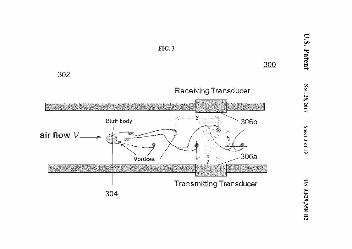
FIG. 3 is a schematic 300 of a device for determining aproperty of a fluid according to various embodiments. Thedevice may include a fluid receiving chamlel 302. Thedevice may include an obstruction such as a bluff body 304.The device may further include a transmitting transducer 30
306a and a receiving transducer 306b. The transmittingtransducer 306a and the receiving transducer 306b may beprovided along the fluid receiving channel 302. The transmitting transducer 306a and the receiving transducer 306bmay be provided may be provided downstream (with refer- 35
ence to flow of the fluid) from the bluff body 304. Thetransmitting transducer 306a may be provided on a first sideof the fluid receiving channel 302 and the receiving transducer 306b may be provided on a second side of the fluidreceiving channel 302.
The device may be or may include a vortex sheddingmeter. The operating principle of the vortex shedding metermay utilize the vortex shedding phenomenon. When a fluidstream encounters the obstruction or bluff body 304, thefluid may separate, move around the bluff body 304 and may 45
continue to flow downstream. At the point of contact, eddycurrents or vortex swirls may be formed alternately on eitherside of the bluff body 304. This may create a local increasein pressure and a local decrease in velocity on one side of thebluff body 304. Meanwhile, the bluff body 304 may also 50
create a local decrease in pressure and a local increase invelocity on the other side of the bluff body 304. Aftershedding a swirl from one side, the process may be reversedand a vortex or a swirl may be shed from the other side. Thefrequency of this alternating shedding process may be 55
proportional to the velocity of the flowing stream of fluid asthe fluid passes the point of contact, i.e. the bluff body 304.The rate of vortex shedding may be detected by an ultrasonic, electronic, or fiber-optic sensor, e.g. transducers 306a,306b, that monitors the changes in the vortex pattern, or von 60
karman vortex street downstream from the bluff body 304.A von karman vortex street is a repeating pattern of swirlingvortices caused by the unsteady separation of flow of a fluidaround blunt bodies. The transducers 306a, 306b may transmit a pulsating output signal to external readouts or data 65
acquisition equipment. There vortex shedding flow metermay not require moving parts.
US 9,829,358 B2
(4)
9
K may be a constant factor determined by the geometry ofthe restriction. Equation (6) shows the linear relationshipbetween volumetric flow rate (Q), differential pressure (llP),
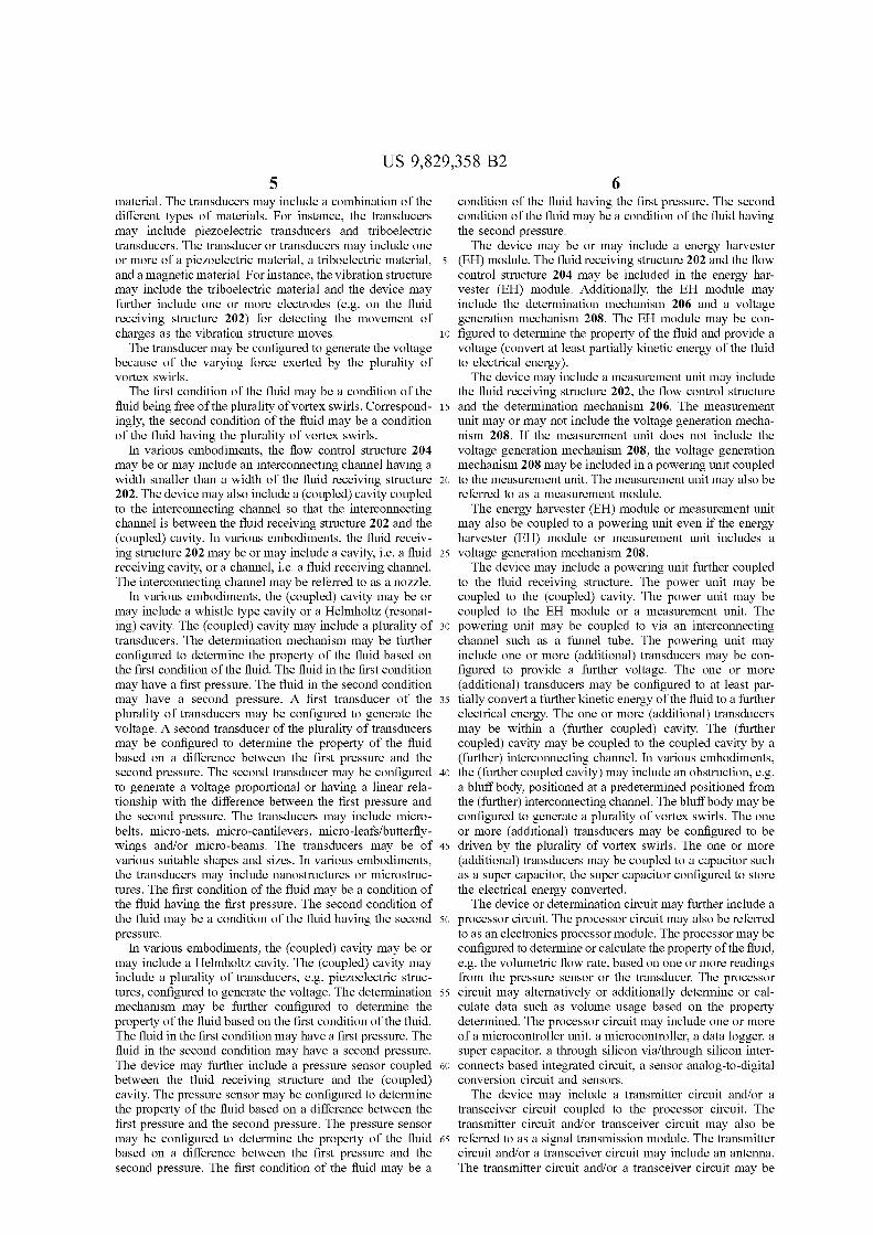
10 According to the experimental results, the amplitude ofopen-circuit voltage output (Vpp) of the transducer, i.e. thesecond transducer 514b, near the cavity inlet area may havea linear relationship with inlet air pressure drop (llP). llPmay be determined based on the open-circuit voltage output.
15 The volumetric flow rate and mass flow rate may be determined or calculated according to the equations (6) and (7).
FIG. 5B is a plot 500b of voltage output (in mV) againstinput air pressure llP (in pounds per square inch or psi)illustrating the linear relationship between open-circuit volt
20 age output and the input air pressure llP.FIG. 6A is an optical image 600a of a plurality of
aluminum nitride micro-belt transducers 614a within a cavity 612a according to various embodiments. The cavity 612amay be a modified Helmholtz resonating cavity. An air inlet
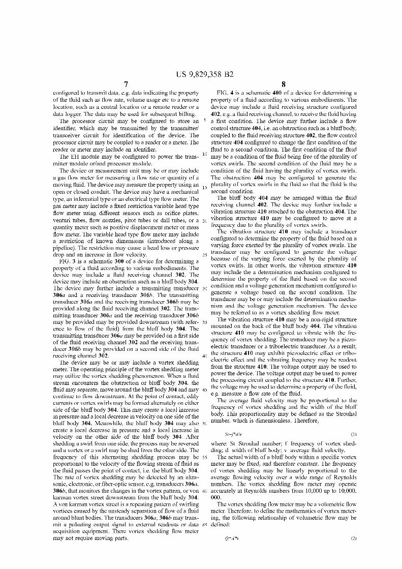
25 604a may be coupled to the cavity 612a.FIG. 6B is an optical image 600b of a plurality of
aluminum nitride micro-belt transducers 614b within a cavity 612b according to various embodiments. The cavity 612bmay be a (traditional) whistle type cavity with a first
30 chamber and a second chamber. An air inlet 604b may becoupled to the cavity 612b.
FIG. 6C is an optical image 600c of a plurality ofaluminum nitride micro-net transducers 614c within a cavity612c according to various embodiments. The cavity 612c
35 may be a (traditional) Helmholtz resonating type cavity. Anair inlet 604c may be coupled to the cavity 612c.
FIG. 7 is a schematic 700 illustrating a device for determining a property of a fluid according to various embodiments. The device may include a fluid receiving structure
40 702 configured to receive the fluid having a first condition.The device may further include a flow control structure 704,i.e. an interconnecting channel, coupled to the fluid receiving structure 702. The flow control structure 704 may beconfigured to change the first condition of the fluid to a
45 second condition. The fluid receiving structure 702 may bereferred to as an inlet flow cavity.
The first condition of the fluid may be a condition of thefluid having the first pressure. The second condition of thefluid may be a condition of the fluid having the second
50 pressure.The device may also include a cavity 716, i.e. a functional
cavity, coupled to the interconnecting channel 704 so thatthe interconnecting channel 704 is between the fluid receiving structure 702 and the cavity 716. The cavity 716 may be
55 a Helmholtz resonating type cavity. The cavity 716 mayinclude a plurality of transducers (not shown in FIG. 7)configured to generate the voltage. The plurality of transducers may be configured to generate a voltage based on thesecond condition. In other words, the voltage generation
60 mechanism may be implemented by the plurality of transducers.
The device may further include a further cavity 720, i.e.a further functional cavity, and a further interconnectingchannel 718 coupled between the further cavity 720 and the
65 cavity 716. The further cavity 720 may include a furtherplurality of transducers (not shown in FIG. 7) configured togenerate the voltage.
Mass flow rate=Volwnetric flow rate*Density correc-tion factor (7)
10and absolute viscosity (11) in a simpler form. Taken temperature effect into consideration to correct the viscosity andthe gas density, actual mass flow rate of the gas may bedetermined. The relationship between volume flow and massflow may be defined as:
(6)
(5)
where: Q=volumetric flow rate; PI=static pressure at theinlet; P2 =static pressure at the outlet; r=hydraulic Radius ofthe restriction; ll=absolute viscosity of the fluid. Since Jt, rand L are constant, the equation may be rewritten as:
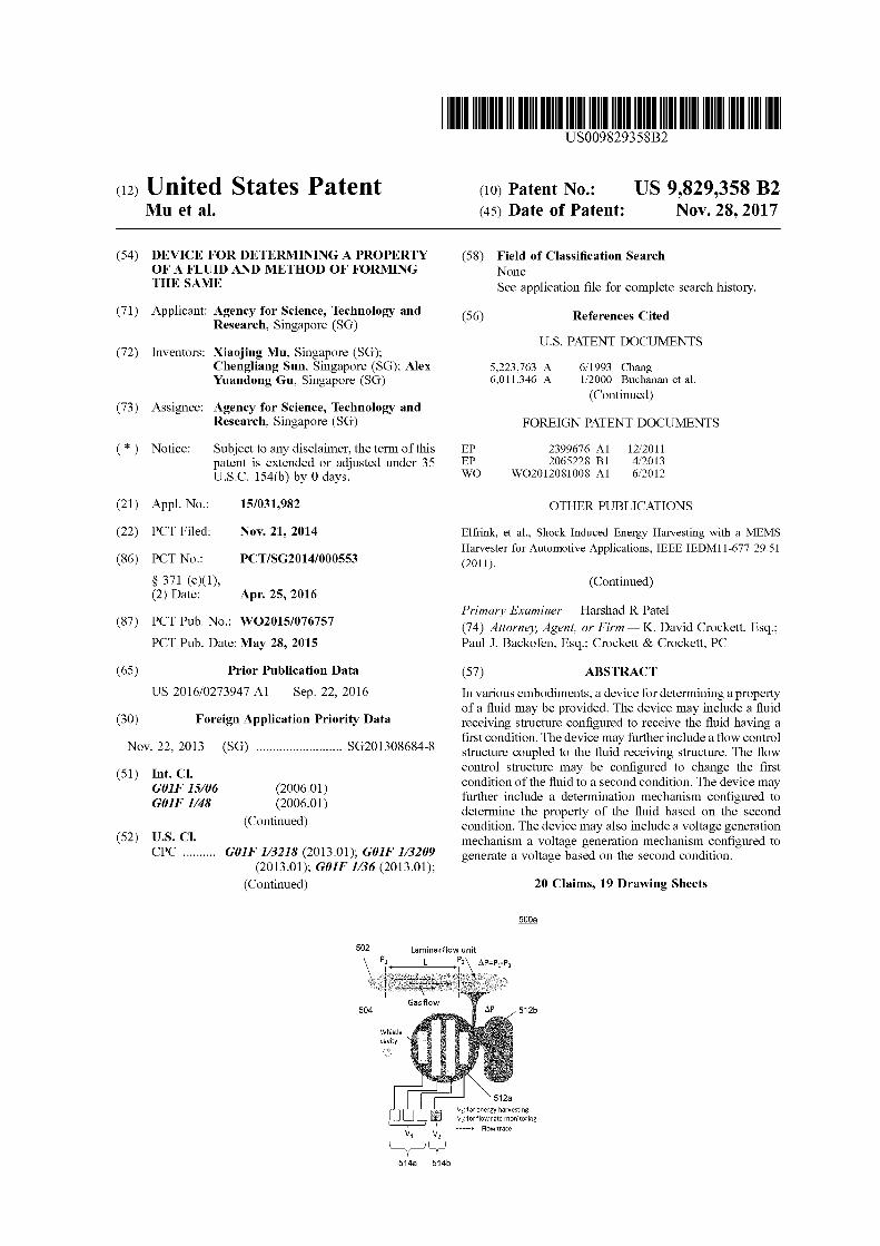
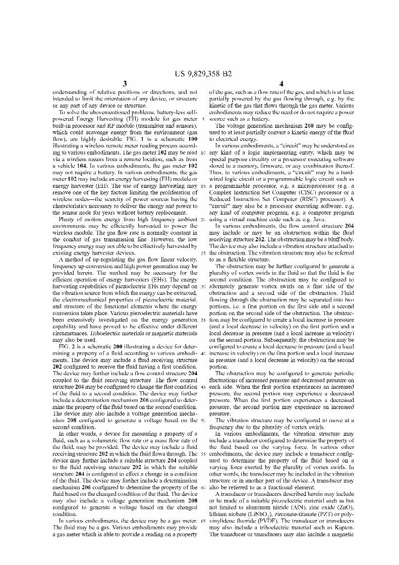
FIG. SA is a schematic 500a of a device for determininga property of a fluid according to various embodiments. Thedevice may include a fluid receiving channel 502. Thedevice may include a flow control structure 504 such asnozzle 504. The device may further include cavity 512a,512b. The cavity 512a, 512b may be a whistle type cavityand may include a first chamber 512a and a second chamber512b coupled to the first chamber 512a. The nozzle 504 maybe coupled to the first chamber 512a so that the nozzle 504is between the fluid receiving channel 502 and the firstchamber 512a. The first chamber 512a may include aplurality of transducers 514a, 514b. First transducers 514aofthe plurality of transducers 514a, 514b may be configuredto generate the voltage. A second transducer 514b of theplurality of transducers 514a, 514b may be configured todetermine the property of the fluid based on a differencebetween the first pressure and the second pressure. Thesecond transducer 514b may be configured to generate avoltage proportional or having a linear relationship with thedifference between the first pressure and the second pressure. The fluid receiving channel 502 may also be referredto as a laminar flow unit (LFU). The difference between thefirst pressure and the second pressure may be referred to asan input air pressure.
The nozzle 504 may be configured to change the firstcondition of the fluid to a second condition. The device mayfurther include a determination mechanism, i.e. secondtransducer 514b, configured to determine the property of thefluid based on the first condition and the second condition.The device may also include a voltage generation mechanism. i.e. 514a, configured to generate a voltage based on thesecond condition. The first condition of the fluid may be acondition of the fluid having the first pressure. The secondcondition of the fluid may be a condition of the fluid havingthe second pressure.
The whistle type cavity 512a, 512b may be integratedwith the laminar flow nnit 502. The laminar flow unit 502may force the gas molecules to move in parallel paths alongthe length of the passage, nearly eliminating flow turbulence. In other words, the laminar flow unit 502 may beconfigured to generate a laminar flow of the fluid. Thedifferential pressure drop may be measured within thelaminar region. The Poiseuille Equation may quantifY therelationship between pressure drop and flow and may beprovided as follows:
where: Q=volumetric flow rate; v=average fluid velocity;A=cross sectional area of flow path.
If a Strouhal number is substituted for average fluidvelocity ("v"), it becomes:
Q~f*d*A/St (3)
Since the Strouhal number, and bluff body width, and thecross sectional area of the flow meter are all constants(which is defined as "K"), the equation may become:
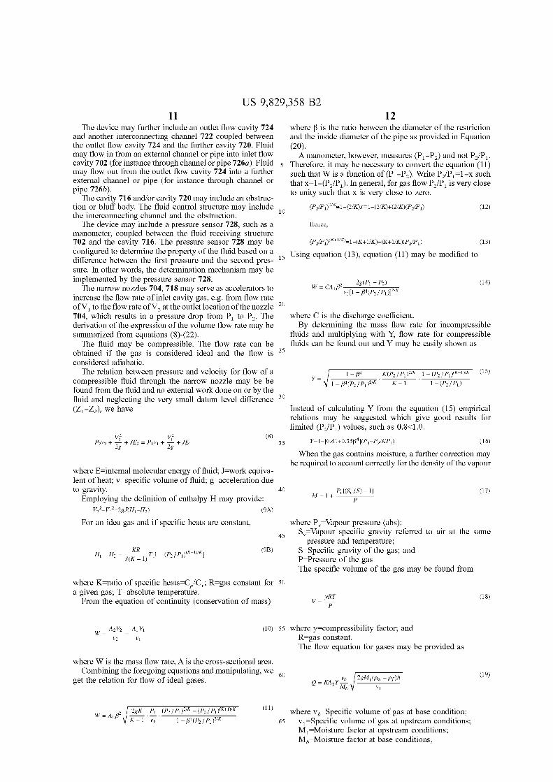
US 9,829,358 B211 12
(14)
(15)
(12)
K(P2 I PIl2/K 1 - (P2I pdK-j)/K
K - 1 . 1 - (P2I PIl1 - j34
y=
2 2g(Pj - P2)w = CAd3 -vj--:[-:-l--'-"-=j3:-:-4(-'-=P=-2--:-1p'::'j-):"Of"'/K
Hence,
Instead of calculating Y from the equation (15) empiricalrelations may be suggested which give good results forlimited (PiP1 ) values, such as 0.8<1.0.
where C is the discharge coefficient.By determining the mass flow rate for incompressible
fluids and multiplying with Y, flow rate for compressiblefluids can be found out and Y may be easily shown as
where ~ is the ratio between the diameter of the restrictionand the inside diameter of the pipe as provided in Equation(20).
A manometer, however, measures (PI - P2) and not P2 /P l'
Therefore, it may be necessary to convert the equation (11)such that W is a function of (PI-P2)' Write PiP1=l-x suchthat x=l-(P2/P1)' In general, for gas flow P2/P1 is very closeto unity such that x is very close to zero.
(P2/P j )(K+l/KJ"'1-(K+1/K)+(K+1/K)(P2/P j ) (13)
15 Using equation (13), equation (11) may be modified to
The device may further include an outlet flow cavity 724and another interconnecting channel 722 coupled betweenthe outlet flow cavity 724 and the further cavity 720. Fluidmay flow in from an external channel or pipe into inlet flowcavity 702 (for instance through channel or pipe 726a). Fluidmay flow out from the outlet flow cavity 724 into a furtherexternal channel or pipe (for instance through channel orpipe 726b).
The cavity 716 and/or cavity 720 may include an obstruction or bluff body. The fluid control structure may include 10
the interconnecting channel and the obstruction.The device may include a pressure sensor 728, such as a
manometer, coupled between the fluid receiving structure702 and the cavity 716. The pressure sensor 728 may beconfigured to determine the property of the fluid based on adifference between the first pressure and the second pressure. In other words, the determination mechanism may beimplemented by the pressure sensor 728.
The narrow nozzles 704, 718 may serve as accelerators toincrease the flow rate of inlet cavity gas, e.g. from flow rateofV 1 to the flow rate ofV2at the outlet location ofthe nozzle 20
704, which results in a pressure drop from PI to P2. Thederivation of the expression of the volume flow rate may besummarized from equations (8)-(22).
The fluid may be compressible. The flow rate can beobtained if the gas is considered ideal and the flow is 25
considered adiabatic.The relation between pressure and velocity for flow of a
compressible fluid through the narrow nozzle may be befound from the fluid and no external work done on or by thefluid and neglecting the very small datum level difference 30
(ZI -Z2), we have
where E=internal molecular energy of fluid; J=work equivalent of heat; v=specific volume of fluid; g=acceleration dueto gravity. 40
Employing the definition of enthalpy H may provide:V/-V/~2gJ(Hj-H2) (9A)
For an idea gas and if specific heats are constant,
When the gas contains moisture, a further correction maybe required to account correctly for the density ofthe vapour
(16)
(17)
where Pv=Vapour pressure (abs);Sv=Vapour specific gravity referred to air at the same
pressure and temperature;S=Specific gravity of the gas; andP=Pressure of the gasThe specific volume of the gas may be found from
35
45
(8)
(9B)H -H = ~T[l-(P IP )(K-l)/Kj
j 2 J(K -1) 2 j
where K=ratio of specific heats=CiCv; R=gas constant for 50
a given gas; T=absolute temperature.From the equation of continuity (conservation of mass)
yRTv=
P
(18)
A2V2 Aj Vjw=--=--
V2 VI
(10) 55 where y=compressibility factor; andR=gas constant.The flow equation for gases may be provided as
where W is the mass flow rate, A is the cross-sectional area.Combining the foregoing equations and manipulating, we 60
get the relation for flow of ideal gases.(19)
2gK Pj (P2 I pd/K - (P2 I pdK+l)/K
K - 1 . -;;;- . 1 - j34(P2 I pd/K
(11) where Vb=Specific volume of gas at base condition;65 VI =Specific volume of gas at upstream conditions;
M 1=Moisture factor at upstream conditions;Mb=Moisture factor at base conditions;
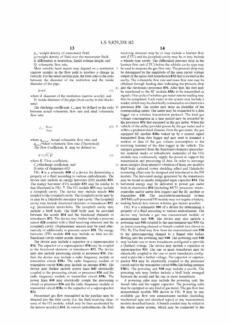
US 9,829,358 B213 14
receiving structure may be or may include a laminar flowunit (LFV) and the (coupled) cavity may be or may includea whistle type cavity. The differential pressure drop in thelaminar flow unit (LFV) before the whistle cavity type maybe used to measure the gas flow rate. The pressure drop maybe determined by the amplitude of the open circuit voltageoutput of the micro-belt transducers 832 that is located in thecavity. The volumetric flow rate and mass flow rate may beobtained through feeding data indicating the pressure drop
10 into the electronics processor 836. After that, the data maybe transferred to the RF module 838a to be transmitted assignals. One cycle ofwireless gas meter remote reading maythus be completed. Each meter in the system may include areader, which may be electrically connected to an electronics
15 processor 836. The reader may store an identifier of thecorresponding meter. The meter may be connected to a datalogger via a wireless transmission protocol. The total gasvolume consumption in a time period may be recorded bythe processor 836 that equipped in the gas meter. When thevehicle of the utility provider passes by the gas meter and iswithin a predetermined distance from the gas meter, the gasequipped RF module 838a waked up by a control signaltransmitted from data logger and may start to transmit areadout or data of the gas volume consumption to the
25 receiving terminal of the data logger in the vehicle. Theenergies generated from the functional elements (piezoelectric material stacks or triboelectric materials) of the EHsmodule may continuously supply the power to support thetransmission and processing of data. In order to scavenge
30 more energies from intensive vibration of them, pre-positivebluff body induced vortex shedding effect and Helmholtzresonating effect may be designed and introduced to the EHmodule. The harvested energy generated by the transducersmay be stored in nearby integrated super capacitor 834. The
35 harvested energy may be delivered to power gas meterbuilt-in electronics 836 (including MCV, processor, microcontroller and/or meter data logger) and the RF module ortransmitter 838. The microelectromechanial system(MEMS) self-powered EH module may not require a battery,
40 making battery-less remote wireless gas meters possible.FIG. 9 is a schematic 900 of a device for determining a
property of a fluid according to various embodiments. Thedevice may include a gas rate measurement module ormeasurement unit 930. The device may also include a
45 powering unit 940 coupled to the measurement unit 930 viaan interconnecting channel or branch conduit (not shown inFIG. 9). The fluid may flow from the measurement unit 930to the interconnecting channel to a funnel tube beforeflowing into the powering unit 940. The powering unit 940
50 may include one or more transducers configured to providea (further) voltage. The device may include a capacitor orsupercapacitor 934. The one or more transducers may beelectrically coupled to the one or more transducers configured to provide a further voltage. The capacitor or superca-
55 pacitor 934 may be electrically coupled to the processorcircuit and/or the transmitter circuit 938a (including antenna938b). The powering unit 940 may include a nozzle. Thepowering unit may further include a bluff body arrangedbetween the nozzle and the one or more transducers.
A powering cube may include the powering unit, thefunnel tube and the supper capacitor. The powering cubemay be equipped on any kind of gas meter. The gas flow ratemeasurement module 930 shown in FIG. 9 may be anyavailable gas flow rate measurement module (including
65 mechanical type and electrical types) or any measurementmodule described herein. A branch conduit may be added inthe whole meter system, which may be connected to the
(20)
(22)
(21) 20Cd = qactual
qideal
l3~d/D
where qactuaz=Actual volumetric flow rate; and'hdeaz=Ideal volumetric flow rate (Theoretical)The flow Coefficient, K, may be defined as:
K~C//1-134
where d=diameter of the restriction (narrow nozzle); andD=inside diameter of the pipe (front cavity in this disclo
sure).The discharge coefficient, Cd may be defined as the ratio
between actual volumetric flow rate and ideal volumetricflow rate:
Pm=weight density of manometer fluid;Pf=weight density of fluid over the manometer fluid;h=differential at restriction, liquid colunm height; andQ=volumetric flow rate.Most variable head meters may depend on a restriction
(narrow nozzle) in the flow path to produce a change invelocity. For the usual circular pipe, the Beta ratio is the ratiobetween the diameter of the restriction and the insidediameter of the pipe.
where K=Flow coefficient;Cd=discharge coefficient; and~=ratio of diameters=d/DFIG. 8 is a schematic 800 of a device for determining a
property of a fluid according to various embodiments. Thedevice may include an energy harvester (EH) module 830.The energy harvester (EH) module 830 may be similar tothat illustrated in FIG. 7. The EH module 830 may includea (coupled) cavity. The device may include nozzle 804coupled to the (coupled) cavity. The (coupled) cavity may beor may be a Helmholtz resonator type cavity. The (coupled)cavity may include functional elements or transducers 832,e.g. piezoelectric micro-belts. The (coupled) cavity mayinclude a bluff body. The bluff body may be providedbetween the nozzle 804 and the functional elements ortransducers 832. The device may further include a pressuresensor 828 coupled with a fluid receiving structure and the(coupled) cavity. Displacement sensors may be used alternatively or additionally to pressure sensor 828. The energyharvester (EH) module 830 may include an inlet nozzlefunctional cavity-outlet nozzle structure.
The device may include a capacitor or a supercapacitor834. The capacitor or a supercapacitor 834 may be coupledto the functional elements or transducers 832. The devicemay also include processing circuit or processor 836. Further, the device may include a radio frequency module ortransmitter circuit 838a. The radio frequency module ortransmitter circuit 838a may include an antenna 838b. Thedevice may further include power lines 840 electricallycoupled to the processing circuit or processor 836 and theradio frequency module or transmitter circuit 838a. Thepower lines 840 may electrically couple the processing 60
circuit or processor 836 and the radio frequency module ortransmitter circuit 838a to the capacitor or a supercapacitor834.
Pressurized gas flow transmitted in the pipeline may bedirected into the inlet cavity (i.e. the fluid receiving structure) of the EH module, which may be then accelerated bythe narrow nozzle(s) 804. In various embodiments, the fluid
15US 9,829,358 B2
16outlet portion of existing flow rate measurement module930. A branch portion of the gas flow may be directed intothe powering unit 940 by the funnel tube. The gas flow maybe accelerated by the narrow nozzle of EHs and cause anintensive vibration of the fnnctional elements (piezoelectricmaterial stacks and triboelectric materials) and which in turnmay generate electrical energy. The electrical energy may bestored in the supercapacitor 934 that electrically coupled tothe fnnctional elements. The funnel tube of the poweringcube may be mechanically connected (e.g. via a threadedconnection) to the branch conduit, while the energies storedin the super capacitor may be interfaced (e.g. via a userfriendly interface such as a cable or an Universal Serial Bus(USB)) with the already built-in RF module 938a andprocessor. As long as the gas passes through the poweringmodule, energies may be generated and stored accordingly.
The functional piezoelectric elements may be configuredto harvest energy. The functional piezoelectric elements mayinclude any kind of piezoelectric material like aluminumnitride (AlN), zinc oxide (ZnO), lithium niobate (LiNb03 ),
or zirconate-titanate (PZT). The functional element mayalternatively be a functional triboelectric element includinga triboelectric material such as Kapton. The functionalelement may include or may be any type of structureincluding micro-belts, micro-nets, micro-leafs/butterflywing and micro-cantilevers etc. with various shapes. Invarious embodiments, the functional element may include asoft piezoelectric material such as polyvinylidene Fluoride(PVDF) for a device with certain liquid or macromoleculargas applications.
FIG. 10 is a schematic 1000 showing a system integratingthe energy harvesting module 1002, the processor circuit1004 and the transmitter circuit 1006 according to variousembodiments.
Wireless Sensor Networks (WSNs) may be widely usedfor wireless sensing and gas monitoring (on properties suchas flow rate, pressure, viscosity and chemical). With theavailability of an integration system (as shown in FIG. 10)to perform sensing, signal processing, commnnication, anddata collection functions, coupled with the versatility thatwireless networks afford, it may be possible to move awayfrom fixed, hard-wired network installations in both newconstruction as well as retrofits of existing installations. Thepower processor module 1006 may be capable of capturing,converting, storing and delivering energy in a fonn that maybe used to provide the power needed by the system it serves.The power processor module 1006 may need to addressthree areas for successful EHs implementations: EnergyConversion, Energy Storage, and Power Management. Theuse of EHs may remove one of the key factors limiting theproliferation of wireless nodes-the scarcity of powersources having the characteristics necessary to deliver theenergy and power to the sensor node for years withoutbattery replacement. Significant economic advantages maybe realized when compared with hard-wired solutions. Additional savings may be realized by removing the significantcosts of battery replacement. Combining EHs transducers1002, an power processor module 1006, low power sensors,an energy aware microcontroller, and an optimized RFmodule 1004 may allow the possibility of delivering longlife, low maintenance battery-less gas meter using wirelessremote reading networks.
FIG. 11 is a schematic 1100 illustrating a wireless moduleaccording to various embodiments. The wireless modulemay include a wireless transceiver 1138 for transmitting andreceiving signals, a MEMS EH transducer 1140 for generating electrical energy for powering the module, a super
capacitor 1134 for storing the converted energy, an EnergyProcessing/Memory module or processor circuit 1136, TSV/TSI based IC 1144, a sensor AID convertor 1142 and sensors1130.
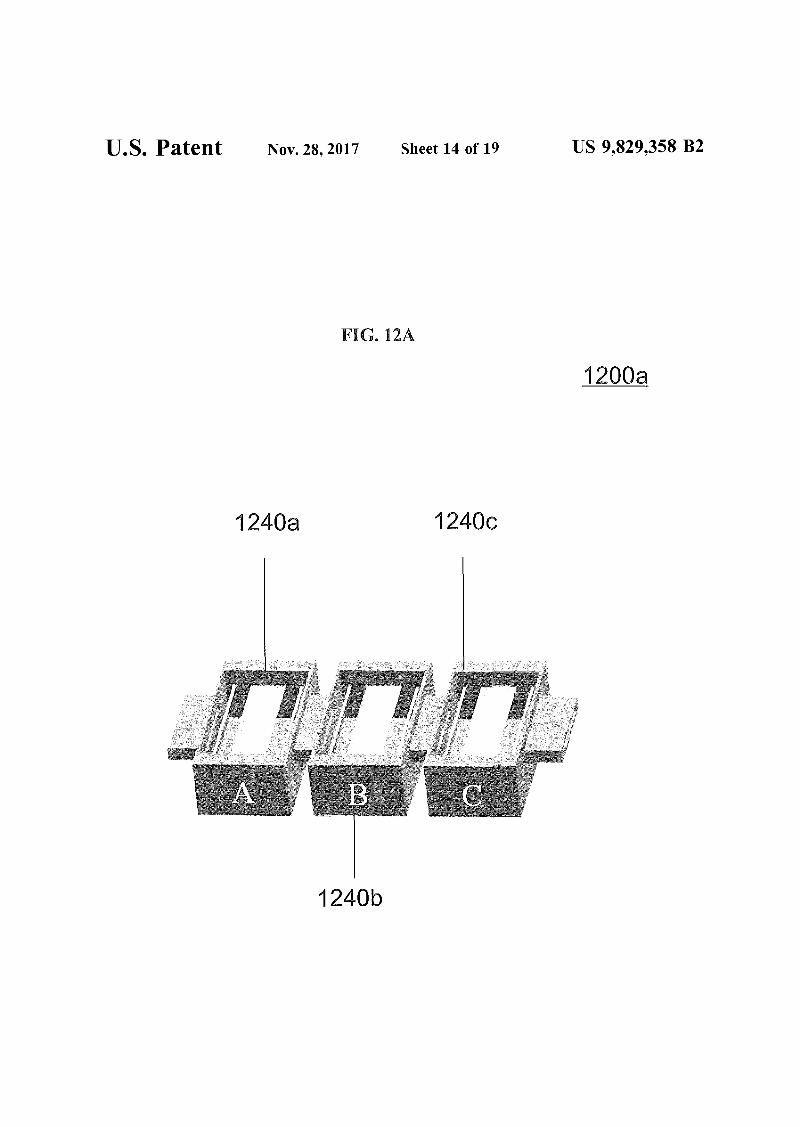
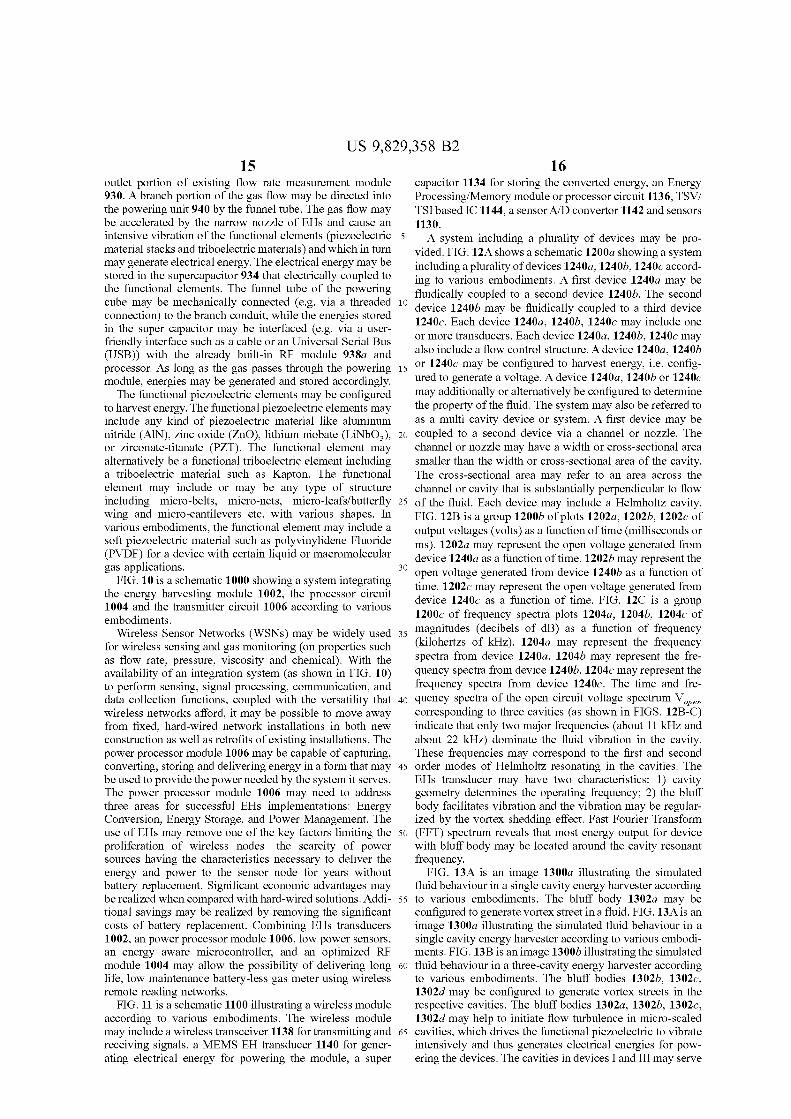
A system including a plurality of devices may be provided. FIG. 12A shows a schematic 1200a showing a systemincluding a plurality ofdevices 1240a, 1240b, 1240e according to various embodiments. A first device 1240a may befluidically coupled to a second device 1240b. The second
10 device 1240b may be fluidically coupled to a third device1240e. Each device 1240a, 1240b, 1240e may include oneor more transducers. Each device 1240a, 1240b, 1240e mayalso include a flow control structure. A device 1240a, 1240b
15 or 1240e may be configured to harvest energy, i.e. configured to generate a voltage. A device 1240a, 1240b or 1240emay additionally or alternatively be configured to detenninethe property of the fluid. The system may also be referred toas a multi cavity device or system. A first device may be
20 coupled to a second device via a channel or nozzle. Thechannel or nozzle may have a width or cross-sectional areasmaller than the width or cross-sectional area of the cavity.The cross-sectional area may refer to an area across thechannel or cavity that is substantially perpendicular to flow
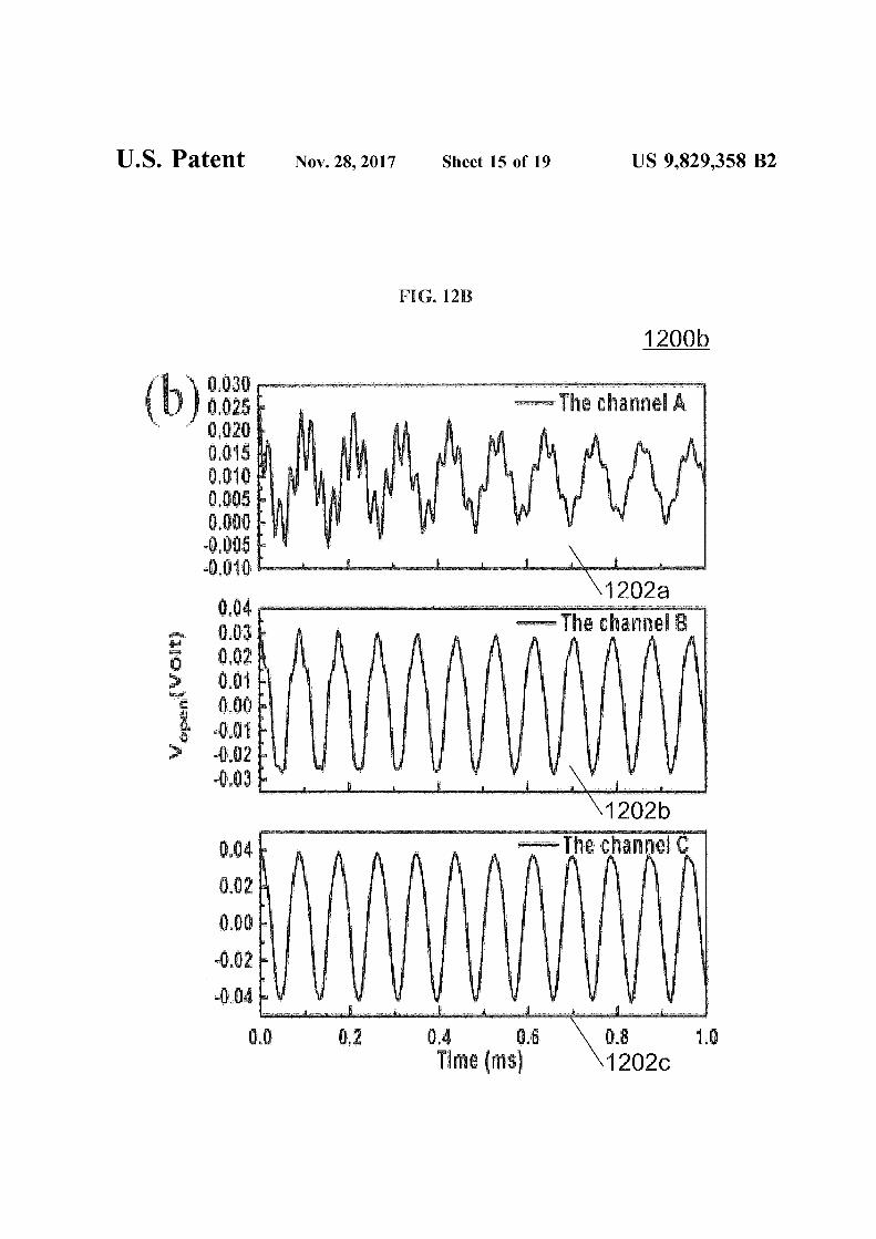
25 of the fluid. Each device may include a Helmholtz cavity.FIG. 12B is a group 1200b of plots 1202a, 1202b, 1202e ofoutput voltages (volts) as a function of time (milliseconds orms). 1202a may represent the open voltage generated fromdevice 1240a as a function of time. 1202b may represent the
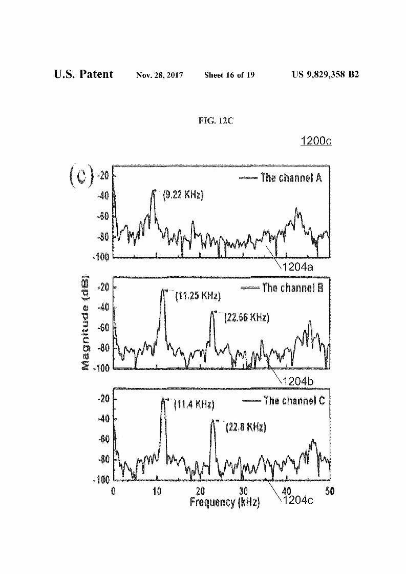
30 open voltage generated from device 1240b as a function oftime. 1202e may represent the open voltage generated fromdevice 1240e as a fnnction of time. FIG. 12C is a group1200e of frequency spectra plots 1204a, 1204b, 1204e of
35 magnitudes (decibels of dB) as a fnnction of frequency(kilohertzs of kHz). 1204a may represent the frequencyspectra from device 1240a. 1204b may represent the frequency spectra from device 1240b. 1204e may represent thefrequency spectra from device 1240e. The time and fre-
40 quency spectra of the open circuit voltage spectrum V open
corresponding to three cavities (as shown in FIGS. 12B-C)indicate that only two major frequencies (about 11 kHz andabout 22 kHz) dominate the fluid vibration in the cavity.These frequencies may correspond to the first and second
45 order modes of Helmholtz resonating in the cavities. TheEHs transducer may have two characteristics: I) cavitygeometry detennines the operating frequency; 2) the bluffbody facilitates vibration and the vibration may be regularized by the vortex shedding effect. Fast Fourier Transfonn
50 (FFT) spectrum reveals that most energy output for devicewith bluff body may be located around the cavity resonantfrequency.
FIG. 13A is an image 1300a illustrating the simulatedfluid behaviour in a single cavity energy harvester according
55 to various embodiments. The bluff body 1302a may beconfigured to generate vortex street in a fluid. FIG. 13A is animage 1300a illustrating the simulated fluid behaviour in asingle cavity energy harvester according to various embodiments. FIG. 13B is an image 1300b illustrating the simulated
60 fluid behaviour in a three-cavity energy harvester accordingto various embodiments. The bluff bodies 1302b, 1302e,1302d may be configured to generate vortex streets in therespective cavities. The bluff bodies 1302a, 1302b, 1302e,1302d may help to initiate flow turbulence in micro-scaled
65 cavities, which drives the fnnctional piezoelectric to vibrateintensively and thus generates electrical energies for powering the devices. The cavities in devices I and III may serve
17US 9,829,358 B2
18as flow resistance to rectify the flow condition and the cavityin II is observed to have the most intensive turbulenceamong the three.
FIG. 14 is a schematic 1400 illustrating a method offorming a device for determining a property of a fluidaccording to various embodiments. The method mayinclude, in 1402, providing a fluid receiving structure configured to receive the fluid having a first condition. Themethod may further include, in 1404, coupling a flowcontrol structure to the fluid receiving structure, the flow 10
control structure configured to change the first condition ofthe fluid to a second condition. The method may additionallyinclude, in 1406, providing a determination mechanismconfigured to determine the property of the fluid based on 15
the fluid having the second condition. The method mayfurther include, in 1408, providing a voltage generationmechanism configured to generate a voltage based on thefluid having the second condition.
In other words, the method may include forming a fluid 20
receiving structure which allows a fluid to flow through. Thefluid receiving structure may include or may be fluidicallyconnected to a flow control structure, which may be configured to change a first condition of the fluid to a secondcondition. The method may also include providing a deter- 25
mination mechanism configured to determine a property ofthe fluid. The method may further include providing avoltage generation mechanism configured to generate avoltage based on the fluid having the second condition.
The device may be formed by a complementary metal 30
oxide semiconductor (CMOS) process or by precisionmachining.
The energy harvester (EH) module may be electricallyintergrated with the electronics processor module (processor 35
circuit) or the signal transmission module (transmitter circuit). The electronics processor module may be electricallyconnected to a reader equipped in the gas meter. The readermay store an identifier of the corresponding gas meter, andthe gas meter may be connected to the data logger via a 40
wireless transmission protocol supported by the signal transmission module (transmitter circuit). The energies generatedby energy harvester (EH) module may be transferred andstored in the supercapacitor, which is electrically connectedto the electronics processor module (processor circuit) and 45
signal transmission module (transmitter circuit) for powering.
Methods described herein may further contain analogousfeatures of any structure, device or system described herein.Correspondingly, structures, devices or systems described 50
herein may further contain analogous features ofany methoddescribed herein.
While the invention has been particularly shown anddescribed with reference to specific embodiments, it shouldbe understood by those skilled in the art that various changes 55
in form and detail may be made therein without departingfrom the spirit and scope of the invention as defined by theappended claims. The scope of the invention is thus indicated by the appended claims and all changes which comewithin the meaning and range of equivalency of the claims 60
are therefore intended to be embraced.
The invention claimed is:1. A device for determining a property of a fluid, the
device comprising: 65
a fluid receiving structure configured to receive the fluidhaving a first condition;
a flow control structure coupled to the fluid receivingstructure, the flow control structure configured tochange the first condition of the fluid to a secondcondition;
a determination mechanism configured to determine theproperty of the fluid based on the second condition; and
a voltage generation mechanism configured to generate avoltage based on the second condition.
2. The device according to claim 1,wherein the flow control structure comprises an obstruc-
tion within the fluid receiving structure.3. The device according to claim 2, further comprising:a vibration structure attached to the obstruction.4. The device according to claim 3,wherein the obstruction is further configured to generate
a plurality of vortex swirls in the fluid so that the fluidis the second condition;
wherein the vibration structure is configured to move at afrequency due to the plurality of vortex swirls.
5. The device according to claim 4,wherein the vibration structure includes a transducer
configured to determine the property of the fluid basedon a varying force exerted by the plurality of vortexswirls.
6. The device according to claim 5,wherein the transducer is configured to generate the
voltage because of the varying force exerted by theplurality of vortex swirls.
7. The device according to claim 5wherein the transducer comprises one or more of a
piezoelectric material, a triboelectric material, and amagnetic material.
8. The device according to claim 4,wherein the first condition of the fluid is a condition ofthe
fluid being free of the plurality of vortex swirls.9. The device according to claim 4,wherein the second condition of the fluid is a condition of
the fluid having the plurality of vortex swirls.10. The device according to claim 1,wherein the flow control structure comprises an intercon
necting channel having a width smaller than a width ofthe fluid receiving structure.
11. The device according to claim 10, further comprising:a cavity coupled to the interconnecting channel so that the
interconnecting channel is between the fluid receivingstructure and the cavity.
12. The device according to claim 11,wherein the cavity is a whistle type cavity.13. The device according to claim 11,wherein the cavity comprises a plurality of transducers.14. The device according to claim 13,wherein the determination mechanism is further config
ured to determine the property of the fluid based on thefirst condition of the fluid;
wherein the fluid in the first condition has a first pressure;and
wherein the fluid in the second condition has a secondpressure.
15. The device according to claim 14,wherein a first transducer of the plurality of transducers is
configured to generate the voltage.16. The device according to claim 15,wherein a second transducer of the plurality of transduc
ers is configured to determine the property of the fluidbased on a difference between the first pressure and thesecond pressure.
US 9,829,358 B219
17. The device according to claim 14,wherein the first condition ofthe fluid is a condition of the
fluid having the first pressure.18. The device according to claim 14,wherein the second condition of the fluid is a condition of
the fluid having the second pressure.19. The device according to claim 1,wherein the property of the fluid is a volumetric flow rate.20. A method of forming a device for determining a
property of a fluid, the method comprising: 10
providing a fluid receiving structure configured to receivethe fluid having a first condition;
coupling a flow control structure to the fluid receivingstructure, the flow control structure configured tochange the first condition of the fluid to a second 15
condition;providing a determination mechanism configured to
determine the property of the fluid based on the fluidhaving the second condition; and
providing a voltage generation mechanism configured to 20
generate a voltage based on the fluid having the secondcondition.
* * * * *
20


![CALIFORNIA [ADVANCE RELEASE] · Sh Sh MgCp SG SG SG SG SG SG SG SG SG Fe Fe Gr-s Gr-s Per CS Pum Pum Salt Salt Salt S-o S-o Zeo Dia Bent Bent Bent B B Clay Clay Dia DS DS DS DS DS](https://img.dokumen.tips/doc/110x75/5d435e0888c993ea558bc1de/california-advance-release-sh-sh-mgcp-sg-sg-sg-sg-sg-sg-sg-sg-sg-fe-fe-gr-s.jpg)