Embed Size (px)
Citation preview
Name ______________________ Date(YY/MM/DD) ______/_________/_______ St.No. __ __ __ __ __ __ __ __ __ Section_________Group #________
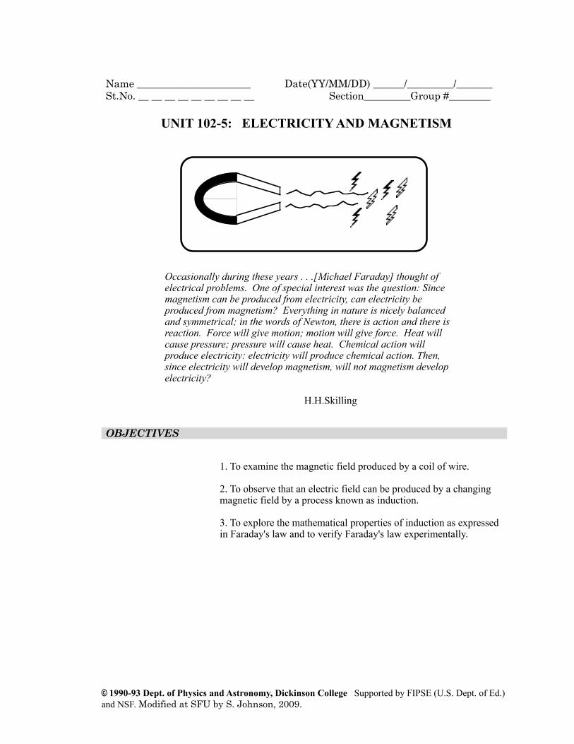
UNIT 102-5: ELECTRICITY AND MAGNETISMApproximate Time Three 100-minute Sessions
Occasionally during these years . . .[Michael Faraday] thought of electrical problems. One of special interest was the question: Since magnetism can be produced from electricity, can electricity be produced from magnetism? Everything in nature is nicely balanced and symmetrical; in the words of Newton, there is action and there is reaction. Force will give motion; motion will give force. Heat will cause pressure; pressure will cause heat. Chemical action will produce electricity: electricity will produce chemical action. Then, since electricity will develop magnetism, will not magnetism develop electricity?
H.H.Skilling
OBJECTIVES
1. To examine the magnetic field produced by a coil of wire.
2. To observe that an electric field can be produced by a changing magnetic field by a process known as induction.
3. To explore the mathematical properties of induction as expressed in Faraday's law and to verify Faraday's law experimentally.
© 1990-93 Dept. of Physics and Astronomy, Dickinson College Supported by FIPSE (U.S. Dept. of Ed.) and NSF. Modified at SFU by S. Johnson, 2009.

OVERVIEW 10 min
In the last unit we saw that an electrical current can produce a magnetic field. This idea came about from an argument, based on Newton’s third law, that if moving charges feel forces as they pass through magnetic fields, they should be capable of exerting forces on the sources of these magnetic fields
Newton's third law and its symmetry, can lead us into even deeper speculation. If charges have electric fields associated with them, then moving charges can be represented mathematically by changing electric fields. Thus, using the concept of "field" to describe forces that act at a distance, we can say that changing electric fields are the cause of magnetic fields. This leads inevitability to the question: If this is so, then, by symmetry, can changing magnetic fields cause electric fields?
In this unit we will explore Faraday's law, which describes how changing magnetic fields produce electric fields and hence electrical currents. Faraday's law lies at the absolute heart of the study of electricity and magnetism. It is one of the two or three most profound laws in classical physics. By using the Biot-Savart law along with Faraday's law, we can describe mathematically how electricity produces magnetism and how magnetism produces electricity. Thus, two seemingly different phenomena, electricity and magnetism, can be treated as aspects of the same phenomenon. At the beginning of the next unit, we will peek briefly at the reformulation of some of the laws of electricity and magnetism which we have already learned into a famous set of four equations known as Maxwell's Equations.
Page 2 Physics for Life Sciences II Activity Guide SFU
© 1990-93 Dept. of Physics and Astronomy, Dickinson College Supported by FIPSE (U.S. Dept. of Ed.) and NSF. Modified at SFU by S. Johnson, 2009.

SESSION ONE: FARADAY'S LAW
The Magnetic Field at the Center of a Current LoopDuring this session you will explore some effects of changing magnetic fields. One way to produce a changing magnetic field is by varying the current in a loop of wire. Let's predict and observe the direction and relative magnitude of the magnetic field inside a coil consisting of one or more circular loops of wire as shown in the diagram below.
Figure 5-1: A wire loop carrying a current I.
In order to predict the direction of the magnetic field at the centre of the coil due to the current in one of its loops you can use the rule you devised and explained in Activity 4-11(b).
For the prediction and investigation of the magnetic field in the centre of a current loop, you'll need the following:
• An insulated wire, 1m long (16 AWG w/ thermoplastic insulation) • A fresh 1.5 V D-cell battery plus holder • A SPST switch • 2 alligator clip leads, > 10 cm • A small compass • A LabPro system • An MG-BTA Vernier Magnetic Field Sensor • An ammeter, 1A • A 3” length of wooden dowel
Physics for Life Sciences II: Unit 102-5 – Electricity & Magnetism Page 3Authors: Priscilla Laws, John Luetzelschwab
© 1990-93 Dept. of Physics and Astronomy, Dickinson College Supported by FIPSE (U.S. Dept. of Ed.) and NSF. Modified at SFU by S. Johnson, 2009.

Activity 5-1: The Magnetic Field in a Loop(a) On the basis of your observation of the magnetic field surrounding a straight wire, what direction do you think the magnetic field will be in the centre of the single loop shown in Figure 5-1 above? How do you expect the magnitude of the field at the centre of the loop to change if you make two loops? Three loops? Cite evidence from previous observations to support your prediction.
(b) Wrap the wire once around the dowel, making a single loop and slip the loop off the dowel. Set up a current through the loop in the direction shown in Figure 5-1 above. Use a compass to determine the direction of the magnetic field at the center of the loop and sketch the direction in the space below. How does it compare with your prediction?
(c) To eliminate the effects of the Earth’s magnetic field, open the L270601 experiment file in LoggerPro and zero the magnetic field sensor in place with the current turned off. Then connect the circuit to measure the magnetic field due to one loop. Next measure the magnitude of the field when you coil the single wire into more loops. Use the ammeter to monitor the current through the wire. You want the current to remain essentially constant. Take these measurements for at least five values of N (N = # of loops) and record them in the table below.
Note: (1) Tape the sensor to the table so it does not move as you add loops. (2) Use the lower amplification setting on the magnetic field sensor. (3) DO NOT leave the current in the wire for more than a few seconds at a time or the battery will wear out.
Page 4 Physics for Life Sciences II Activity Guide SFU
© 1990-93 Dept. of Physics and Astronomy, Dickinson College Supported by FIPSE (U.S. Dept. of Ed.) and NSF. Modified at SFU by S. Johnson, 2009.

N B
1
2
3
4
5
(d) Make a graph in Excel of B vs. N. Submit your graph to WebCT. What shape is your graph? Do your observations agree with your prediction in part (a) above?
A very useful result of the formal mathematical calculation for a circular coil of wire is that the magnetic field at the centre of the coil is proportional to the current flowing through its windings and to the number of turns of wire in the coil. Thus, we will be using the expression
B ∝ NI
in the next session as we explore Faraday's Law.
Michael Faraday's QuestIn the nineteenth century, the production of a magnetic field by a current-carrying wire was regarded as the creation of magnetism from electricity. This led investigators to a related question: Can magnetism create an electric field capable of causing current to flow in a wire? Michael Faraday, thought by many to be the greatest experimental physicist of the nineteenth century, attempted numerous times to produce electricity from magnetism. He reportedly put a wire that was connected to a galvanometer near a strong magnet, but no current flowed in the wire. Faraday realized that getting current to flow would involve a kind of perpetual motion unless the magnet were to lose some of its magnetism in the process. Although the law of conservation of energy had not yet been formulated, Faraday had
Physics for Life Sciences II: Unit 102-5 – Electricity & Magnetism Page 5Authors: Priscilla Laws, John Luetzelschwab
© 1990-93 Dept. of Physics and Astronomy, Dickinson College Supported by FIPSE (U.S. Dept. of Ed.) and NSF. Modified at SFU by S. Johnson, 2009.

an intuitive feeling that the process of placing a wire near a magnet should not lead to the production of electrical current.
Faraday fiddled with this problem off and on for ten years before discovering that he could produce a current in a coil of wire with a changing magnetic field. This seemingly small feat has had a profound impact on civilization. Most of the electrical energy that has been produced since the early nineteenth century has been produced by changing magnetic fields! This process has come to be known as induction.
To make some qualitative observations on electric field "induction" and associated currents, you'll need:
• A galvanometer • 3-4 assorted wire coils (with different areas and numbers of turns) • 2 alligator clip leads • 2 bar magnets • A strong horseshoe magnet
The goal of these observations is two-fold – first, to get a feel for what induction is like, and second, to discover what factors influence the amount of current induced in the coil. To start your observations you should wire one of the coils in series with a galvanometer and fiddle around with the bar magnet in the vicinity of the coil.
Activity 5-2: Current from a Coil and Magnet (a) Play around with the coils attached to the galvanometer one at a time and the magnets and make a list of as many factors as possible that will determine the maximum current that can be induced in the coil. Some suggestions are: the proximity of the magnet to the coil, the speed with which you move the magnet etc... (Each coil has a characteristic resistance and whenever a current is induced in it there is a potential difference created across the coil. This magnetically generated potential difference is called an electromotive force or emf.)
Page 6 Physics for Life Sciences II Activity Guide SFU
© 1990-93 Dept. of Physics and Astronomy, Dickinson College Supported by FIPSE (U.S. Dept. of Ed.) and NSF. Modified at SFU by S. Johnson, 2009.

(b) Is it possible to have a current or emf in the coil when the magnetic field is not changing in the centre of the coil? If necessary, make more observations and explain your results.
This is a good time to make more careful observations on the relationship between various factors that influence the magnitude of the emf induced in a coil. In the next activity you will look at factors one at a time and make more detailed observations on the effects. See if you can hypothesize a simple mathematical relationship for each factor. For example, you might find that the emf increases with the cross sectional area of the coil. This could lead you to the intelligent guess (that's what's meant by a hypothesis) that the emf induced in a coil is proportional to its area (emf ∝ A), and so on.
Activity 5-3: Describing an Induced EMF(a) How do you think the emf induced in a coil depends on the rate at which the magnetic field changes in it? Hint: Is there any emf induced whenever the magnet and coil are at rest relative to each other?
(b) How do you predict the emf induced in a coil depends on the area of the coil?
(c) How do you predict the emf induced in a coil depends on the number of turns in the coil?
Physics for Life Sciences II: Unit 102-5 – Electricity & Magnetism Page 7Authors: Priscilla Laws, John Luetzelschwab
© 1990-93 Dept. of Physics and Astronomy, Dickinson College Supported by FIPSE (U.S. Dept. of Ed.) and NSF. Modified at SFU by S. Johnson, 2009.
(d) Are there any other factors that you think might influence the emf?
(e) Check with some of your classmates and find out what relationships they are hypothesizing for other factors. Write down a trial equation that describes the induction of an emf as a function of the factors you think are important.
20 min Some Observations of Magnetic Induction
You should be convinced by now that: (1) currents can be induced in a conductor in the presence of a changing magnetic field; and (2) currents cause magnetic fields. Let's observe two phenomena that depend on one or both of these two facts using the following equipment. We have one set-up for the entire class that we will take turns with:
• A solenoid with an 110 VAC plug • A pickup coil w/ a small bulb attached (w/ a larger diameter than the solenoid) • A small metal ring • A small metal ring with a vertical cut • An aluminum tube • A strong cylindrical dipole magnet that fits in the tube
Phenomenon #1: Magnet, Pickup Coil & Light BulbSuppose a 60 Hertz alternating current is fed into a solenoid (which consists of a long wire wound into a series of circular wire loops) to create an electromagnet with a changing magnetic field with dB/dt = Asinωt. What happens when a coil of wire, with a light bulb attached to it, is placed over the solenoid as shown in Figure 5-2 below? How about if a metal ring is placed over it and it is suddenly turned on?
Page 8 Physics for Life Sciences II Activity Guide SFU
© 1990-93 Dept. of Physics and Astronomy, Dickinson College Supported by FIPSE (U.S. Dept. of Ed.) and NSF. Modified at SFU by S. Johnson, 2009.

Figure 5-2: A pickup coil with light bulb attached in series surrounding a solenoid but not touching it.
Phenomenon #2: The Metal Tube and CylindersSuppose a non-magnetic cylindrical metal object is dropped through a non-magnetic metal tube. What will happen? How fast will it fall? Suppose a cylindrical magnet is dropped through the same metal tube. What might be different? Why?
Activity 5-4: Induction Phenomena(a) What did you predict for phenomenon #1, in which a coil with a bulb attached to it surrounds a changing magnetic field? What did you see? How about the ring(s)?
(b) Using what you’ve learned so far in this Unit explain phenomenon #1.
Physics for Life Sciences II: Unit 102-5 – Electricity & Magnetism Page 9Authors: Priscilla Laws, John Luetzelschwab
© 1990-93 Dept. of Physics and Astronomy, Dickinson College Supported by FIPSE (U.S. Dept. of Ed.) and NSF. Modified at SFU by S. Johnson, 2009.

(c) What did you predict for phenomenon #2, in which two objects are dropped down a conducting tube? What did you see?
(d) Explain phenomenon #2.
minA Mathematical Representation of Faraday's Law By performing a series of quantitative experiments on induction, it can be shown that the emf induced in a coil of wire is given by the equation
! = !N
!"B
!t
where the magnetic flux through a single loop of the coil !B is given by the expression
!B = !B · !A
where
€
r B is the average magnetic field inside the coil, and
€
r A is a
vector whose magnitude is the cross-sectional area of the coil and whose direction is given by the normal to that cross-section. N is the number of loops in the coil of wire. Thus, Faraday's Law relating emf to flux can be written in two alternate forms:
! = !N
!"B
!t= !N
!( "B · "A)
!t
Page 10 Physics for Life Sciences II Activity Guide SFU
© 1990-93 Dept. of Physics and Astronomy, Dickinson College Supported by FIPSE (U.S. Dept. of Ed.) and NSF. Modified at SFU by S. Johnson, 2009.

Figure 5-3: Magnetic flux through an area A is the dot product of the magnetic field vector and the vector normal to the area.
Whenever the plane of a coil of area A is perpendicular to the magnetic field vector, then the dot product can be dropped and the equation for the emf can be written in terms of vector components along a common axis (in this case called the z-axis) so that:
! = !NAz
!Bz
!t
Computing Flux from Currents in a Loop as a Function of Time A loop of wire known as a pickup coil has a radius R and N turns. Suppose it is placed perpendicular to a uniform magnetic field B that varies with time so that
B = Bo sinωt
where Bo is a constant representing the amplitude of the magnetic field.
Activity 5-5: Applying Faraday's Law to a Wire Loop(a) What is the equation for the flux through a single loop of the coil in terms of R, Bo, ω and t?
Physics for Life Sciences II: Unit 102-5 – Electricity & Magnetism Page 11Authors: Priscilla Laws, John Luetzelschwab
© 1990-93 Dept. of Physics and Astronomy, Dickinson College Supported by FIPSE (U.S. Dept. of Ed.) and NSF. Modified at SFU by S. Johnson, 2009.

(b) According to Faraday's law, what is the equation for the emf in the pickup coil in terms of N, R, Bo ω and t? Hint: Assume that !(sin(!t))/!t = cos(!t)
(c) In the space below sketch two graphs – one showing the shape of the B vs. t graph for at least two complete cycles and one showing the shape of the emf vs. t graph for the same two cycles. Be careful to line the two graphs up properly!
(d) Suppose that the magnetic field varies over time in a triangular fashion, as shown in the diagram below. Sketch the shape of the induced emf function in the space below.
Hints: (1) It is not the same as the emf in part (c). (2) Remember that !B/!t is the slope of the B vs. t graph for a given interval.
Page 12 Physics for Life Sciences II Activity Guide SFU
© 1990-93 Dept. of Physics and Astronomy, Dickinson College Supported by FIPSE (U.S. Dept. of Ed.) and NSF. Modified at SFU by S. Johnson, 2009.

SESSION TWO: VERIFICATION OF FARADAY'S LAW100 min
Verifying Faraday's Law Quantitatively Your mission, should you choose to accept it, is to do aquantitative investigation of the emf in a pickup coil as a function of the rate of change of the flux through it to see if
! = !N
!"B
!t In this project you can use one current-carrying wire to create a magnetic field that induces an EMF in a second coil. The first of these coils, called the field coil, can have a changing current from a function generator pushed through it. The magnetic field that is produced in the centre of the field coil also varies with time and is proportional to the current in the field coil. An inner coil, called the pickup coil, will have a current induced in it as a result of the time-varying magnetic field. A dual trace oscilloscope can be used to display both the current in the field coil and the emf induced in the pickup coil. For this activity and the next you will need the following equipment:
• A large flat 200 turn field coil • A ~1100 turn pickup coil mounted on a long flat wooden rod • A 1.2kΩ resistor and a 10kΩ resistor • A function generator • An oscilloscope • 2 female banana plug to male BNC connectors • A BNC T-connector • A BNC cable • 2 banana plug leads • 2 banana to alligator clip leads • A ruler • A Vernier calliper • A protractor
The experimental setup which is pictured below can be used to take measurements of the induced emf in the pickup coil as a function of the time rate of change of the magnetic flux in the central region of the pickup coil.
Physics for Life Sciences II: Unit 102-5 – Electricity & Magnetism Page 13Authors: Priscilla Laws, John Luetzelschwab
© 1990-93 Dept. of Physics and Astronomy, Dickinson College Supported by FIPSE (U.S. Dept. of Ed.) and NSF. Modified at SFU by S. Johnson, 2009.

Figure 5-4: Faraday's Law Apparatus
In order to verify Faraday's law you need to use the standard equation for the magnitude of the magnetic field at the centre of the field coil. This equation, which is derived in most introductory physics texts, is given by
€
Bz =µ0N f I2R
where R is the radius of the field coil and Nf is the number of turns in the field coil. If the normal vector of the pickup coil makes an angle θ with the magnetic field vector
€
r B then
!B = !B · !A =
!µ0NfAcos"
2R
"I
Thus, for a fixed angle between
€
r B and
€
r A , the flux,!B , through the
pickup coil is directly proportional to the current I. So the change in flux !"B/!t will also be directly proportional to !I/!t. This is important!
Thus, you need to generate a changing magnetic flux in the centre of the field coil by changing the current in the field coil. You can then see how the changing flux affects the emf that is induced in the pickup coil.
Page 14 Physics for Life Sciences II Activity Guide SFU
© 1990-93 Dept. of Physics and Astronomy, Dickinson College Supported by FIPSE (U.S. Dept. of Ed.) and NSF. Modified at SFU by S. Johnson, 2009.

The first step is to connect the wave generator to the field coil and to the oscilloscope (as shown in the diagram above) and put a changing current (in the form of a 1000 hertz triangle wave) into the field coil from the wave generator. Note that the voltage drop, VA, across the 1200Ω resistor, Ri, can be measured by the oscilloscope from the input A readings for voltage. Ohm's law can then be used to calculate the current, I, in the field coil.
The rate of change of the magnetic flux through the pickup coil is proportional to the rate of change of the current in the field coil. Let's consider a plot of the triangle wave representing the change in current as a function of time as shown in Figure 5-5 below.
Figure 5-5: A graph of current vs. time in the field coil when a triangle wave form is fed into a field coil.
It can be seen from the plot above that, when the slope of the triangle wave is positive,
slope =
!I
!t=
Imax ! Imin
T/2
If the frequency of the wave is set at f on the wave generator, we can use the fact that T= (1/f) to find the slope in terms of f.
slope =
!I
!t= 2f(Imax ! Imin)
Noting that the negative slope has the same magnitude, it is clear that in general
slope =
!I
!t= ±2f(Imax ! Imin)
By using the equation given previously for magnetic flux:
Physics for Life Sciences II: Unit 102-5 – Electricity & Magnetism Page 15Authors: Priscilla Laws, John Luetzelschwab
© 1990-93 Dept. of Physics and Astronomy, Dickinson College Supported by FIPSE (U.S. Dept. of Ed.) and NSF. Modified at SFU by S. Johnson, 2009.

!B = !B · !A =
!µ0NfAcos"
2R
"I
we can find the rate of change of magnetic flux through each single loop in the pickup coil:
!"B
!t=
!µ0NfAcos!
2R
"!I
!t
and finally for our situation with
€
θ = 0:
!"B
!t= ±
!µ0NfA
2R
"2f(Imax ! Imin)
Where
Nf is the number of turns in the field coil R is the radius of the field coil, and A is the area of the pickup coil
To determine the emf induced in the pickup coil, you should connect the pickup coil and the 10kΩ resistor in parallel with the oscilloscope as shown in Figure 5-4 above.
If Faraday’s Law holds, then the magnitude of measured electromotive force induced in the pickup coil should be equal to the calculated value of
emf = Np
!"B
!t
where
€
Np is the number of turns in the pickup coil. A graph of measured emf vs. !"B/!t would therefore produce a linear curve with a slope of
€
Np .
Page 16 Physics for Life Sciences II Activity Guide SFU
© 1990-93 Dept. of Physics and Astronomy, Dickinson College Supported by FIPSE (U.S. Dept. of Ed.) and NSF. Modified at SFU by S. Johnson, 2009.

Activity 5-6: Results: emf vs. !"B/!t
(a) The emf induced in the pickup coil is given by 0.5VB where VB is the difference between the maximum and minimum voltage from the pickup coil as recorded on input B of the oscilloscope. Explain why emf = 0.5VB rather than VB.
(b) Vary the output frequency of the triangular wave between about 200 and 1000 hertz. Record the value of emf as a function of frequency in the table below.
f(Hz) emf(V) !"B/!t (V)
200
400
600
800
1000
(c) Use the values of Imax and Imin and the frequency etc... to calculate !"B/!t for each frequency. Hint: Use the data for
VAmax and VAmin and the value of the input resistor Ri to find Imax and Imin. Show one sample calculation below. Be careful with your units! Enter the values you get in the table above.
Physics for Life Sciences II: Unit 102-5 – Electricity & Magnetism Page 17Authors: Priscilla Laws, John Luetzelschwab
© 1990-93 Dept. of Physics and Astronomy, Dickinson College Supported by FIPSE (U.S. Dept. of Ed.) and NSF. Modified at SFU by S. Johnson, 2009.

(d) Plot emf vs. !"B/!t in Excel. What is the value of the slope of the graph? What does the theory say the slope should be? Is your value about right? Submit your graph and spreadsheet to WebCT.
(e) Does Faraday's law seem to hold? Explain why or why not.
Page 18 Physics for Life Sciences II Activity Guide SFU
© 1990-93 Dept. of Physics and Astronomy, Dickinson College Supported by FIPSE (U.S. Dept. of Ed.) and NSF. Modified at SFU by S. Johnson, 2009.

Flux as a Function of AngleSo far you have concentrated on measuring emf as a function of the wave form that causes a time varying magnetic field at the site of the pickup coil. Suppose the normal vector for the pickup coil makes an angle θ with respect to the normal vector of the field coil. If you hold everything else the same, what happens to the maximum emf induced in the pickup coil?
Activity 5-7: Experimental Results: emf vs. θ(a) Sketch a graph of the predicted induced emf as a function of the angle between the field coil and the pickup coil in the space below. Do this for angles between 0o and 180o and explain the theory behind your prediction. Hint: How does
!B = !B · !A
depend on the angle? Please label the axes and specify units.
(b) Set up an experiment to measure the emf of a changing magnetic field at the site of the pickup coil as a function of angle for at least six angles between 0o and 180o. Record your data in the table below.
Angle emf(V)
Physics for Life Sciences II: Unit 102-5 – Electricity & Magnetism Page 19Authors: Priscilla Laws, John Luetzelschwab
© 1990-93 Dept. of Physics and Astronomy, Dickinson College Supported by FIPSE (U.S. Dept. of Ed.) and NSF. Modified at SFU by S. Johnson, 2009.

(c) Create a graph of emf vs angle in Excel. Submit your graph to WebCT.
(d) How did your results compare with your prediction?
10 min
Page 20 Physics for Life Sciences II Activity Guide SFU
© 1990-93 Dept. of Physics and Astronomy, Dickinson College Supported by FIPSE (U.S. Dept. of Ed.) and NSF. Modified at SFU by S. Johnson, 2009.