Embed Size (px)
Citation preview

User Manual
Edition 1.0
OmniBAS Driver
Confidential

INTRACOM TELECOM19.7 km Markopoulou Ave., Peania, Athens, GR 19002
T +30 210 667 1000, F +30 210 667 1001http://www.intracom-telecom.com
The information contained in this document is subject to change without prior notice.
ã INTRACOM S.A. TELECOM SOLUTIONS, 2011. All rights reserved.
All copyright, intellectual and industrial rights in this document and in the technical knowledge it containsare owned by INTRACOM S.A. TELECOM SOLUTIONS and/or their respective owners.
This document is made available to the end users only for their internal use.No part of this document nor any data herein may be published, disclosed, copied, reproduced,redistributed by any form or means, electronically or mechanically, or used for any other purposewhatsoever without the prior written approval of INTRACOM S.A. TELECOM SOLUTIONS.Information as well as drawings and specifications contained in this document are subject to changewithout prior notice.
All trademarks and copyrights mentioned herein are the property of INTRACOM S.A. TELECOMSOLUTIONS and/or their respective owners.Any rights not expressly granted herein are reserved.
Printed in Greece.
Table of Contents OmniBAS Node ManagerUser Manual - Edition 1.0
1
Table of Contents
1 Introduction ................................................................................................................... 5About this Document....................................................................................................... 5Minimum HW / SW Requirements................................................................................... 6
2 Getting Started .............................................................................................................. 7Connecting OmniBAS Node Manager ............................................................................. 7Logging In / Logging Out Procedures............................................................................ 11Configuring Management Parameters........................................................................... 15
3 GUI Overview............................................................................................................... 19Main Window ................................................................................................................ 19Menu Bar ...................................................................................................................... 22Graphical View - OmniBAS-2W/ 4W MEs Representation............................................. 23Graphical View Indications ............................................................................................ 27Refresh Processes........................................................................................................ 30Main Buttons Description .............................................................................................. 33GUI Customization........................................................................................................ 35
4 Before Starting OmniBAS-2W/ 4W Management....................................................... 41Checking OmniBAS Node Manager Release ................................................................ 41Selecting OmniBAS-2W/ 4W Managed Elements/ Objects............................................ 42General Guidelines for Performing Management Actions.............................................. 46Configuration Tabbed Sheets........................................................................................ 50Active Alarms & Real Time Events Lists........................................................................ 53Filtering a List (Active Alarms or Real Time Events)...................................................... 55Exporting an Active Alarms or Real Time Events List .................................................... 60
5 Configuring an OmniBAS-2W/ 4W ME ....................................................................... 645.1 Quick (& First) Configuration of OmniBAS-2W/ 4W ME................................................. 65
5.2 Configuring Control Card............................................................................................... 72Setting Real Time Clock................................................................................................ 73Configuring OmniBAS-2W/ 4W System Synchronization............................................... 74Configuring Modems' Operational Mode ....................................................................... 80Configuring GbE/ FE Ports............................................................................................ 83Configuring the E1 Ports ............................................................................................... 87
5.3 Configuring Modem Parameters.................................................................................... 89
5.4 Configuring ODU Parameters........................................................................................ 94Enabling/ Disabling ODU Mute & DC Power ................................................................. 95Setting Tx Frequency and Tx Power ............................................................................. 96Setting RSSI & Temperature Alarm Thresholds ............................................................ 98Setting Update Mode of ODU........................................................................................ 99
6 Configuring OmniBAS-2W/ 4W Bridge Functionality ............................................. 100Setting Bridge Parameters .......................................................................................... 101Configuring L2 Ports ................................................................................................... 105

OmniBAS Node ManagerUser Manual - Edition 1.0
Table of Contents
2
Configuring Ethernet QoS ........................................................................................... 113Configuring Policer Parameters................................................................................... 121Configuring Service Flows........................................................................................... 130Configuring Forwarding Process ................................................................................. 138
7 Service Provisioning................................................................................................. 143General Procedures (Examples) ................................................................................. 143Configuring VLAN List................................................................................................. 146Associating VLANs with L2 Port .................................................................................. 152Creating (or Removing) a PWE TDM Connection........................................................ 156
8 Loopback Tests......................................................................................................... 161Performing Loopback Tests in E1 Lines ...................................................................... 161Enabling/ Disabling ODU Loopback ............................................................................ 165
9 Maintaining the OmniBAS-2W/ 4W MEs .................................................................. 166Saving OmniBAS-2W/ 4W ME Configuration .............................................................. 167Synchronizing an OmniBAS-2W/ 4W ME .................................................................... 168Adding/ Removing a Trap Destination ......................................................................... 169Performing a Backup or Restore Action ...................................................................... 172Upgrading the Firmware of an OmniBAS Link ............................................................. 175Updating an ODU........................................................................................................ 178
10 Performing Reset Actions ........................................................................................ 179Resetting a Modem Card ............................................................................................ 179Restarting an ODU...................................................................................................... 180Resetting an OmniBAS-2W/ 4W ME ........................................................................... 181Clearing OmniBAS-2W/ 4W ME Configuration ............................................................ 182Unlocking Filesystem .................................................................................................. 183
11 Monitoring the Status of an OmniBAS-2W/ 4W ME................................................. 184Monitoring Inventory Information ................................................................................. 184Monitoring the Link Status of an OmniBAS-2W/ 4W ME.............................................. 189Monitoring General Info about OmniBAS-2W/ 4W ME................................................. 192Monitoring the Status of the OmniBAS-2W/ 4W Control Card ..................................... 193Monitoring the Status of the OmniBAS-4W FAN Tray / PSUs...................................... 197Monitoring the Status of the OmniBAS-4W Interface Card .......................................... 202Monitoring the Status of FE & GbE Ports .................................................................... 203Monitoring the Status of E1 Ports................................................................................ 208Monitoring the Status of a Modem Card ...................................................................... 211Monitoring the Status of an ODU................................................................................. 216
12 Monitoring the Real-Time Performance................................................................... 223Monitoring Real-Time GbE Performance..................................................................... 224Monitoring the Real-Time Modem Performance .......................................................... 228Monitoring the Real-Time Modem Ethernet Performance............................................ 230Monitoring the Real-Time L2 Ports Statistics............................................................... 234Monitoring the Real-Time Performance of a PWE TDM Connection............................ 237

Table of Contents OmniBAS Node ManagerUser Manual - Edition 1.0
3
13 Fault Management..................................................................................................... 239Viewing Active Alarms................................................................................................. 240Alarms Properties........................................................................................................ 243Active Alarms Toolbar ................................................................................................. 245Acknowledging an Alarm............................................................................................. 246Clearing an Alarm ....................................................................................................... 247Alarms Supported by OmniBAS Node Manager.......................................................... 248
14 Monitoring Real Time Events ................................................................................... 250Monitoring Real Time Events List................................................................................ 251Real Time Events Properties....................................................................................... 253Real Time Events Toolbar........................................................................................... 256Clearing the Real Time Events List ............................................................................. 257Events Supported by OmniBAS Node Manager .......................................................... 258
Appendix - IEEE 802.1q / ad Ethernet Frames................................................................... 261
Glossary............................................................................................................................... 263

OmniBAS Node ManagerUser Manual - Edition 1.0
Table of Contents
4
(Page intentionally left blank)
Chapter 1. Introduction OmniBAS Node ManagerUser Manual - Edition 1.0
5
1 Introduction
About this Document
Scope ofdocument
The scope of this document is to provide detailed instructions on themanagement of OmniBAS-2W/ 4W systems, through the OmniBAS NodeManager (Release 3.2.0).OmniBAS Node Manager is a portable uni|MS application providing local orremote graphical node management capabilities of up to two OmniBAS-2W/4W Managed Elements (MEs). OmniBAS Node Manager is suitable for fieldinstallation teams and Regional Office staff for management of theOmniBAS-2W/ 4W equipment.
TargetAudience
This document is intended for operators that are responsible for:· Setting-up an OmniBAS-2W/ 4W ME to be managed locally or remotely by
OmniBAS Node Manager.· Configuring, monitoring or troubleshooting an OmniBAS-2W/ 4W node (or
link).
DocumentConventions
This document applies the following conventions:· Bold fonts are used for: buttons, menus/ sub-menus, options, tabs, group
boxes, text boxes, check boxes and drop-down lists.· Italic fonts are used for window names, tabbed sheet names, wizard names
and values of an attribute.
NOTE A note calls your attention to important supplementary information.
This symbol means CAUTION. The purpose of this symbol is toprevent you from performing an action that might result in damage ofthe equipment or loss of data.
DocumentWarranty
· The information contained in this document is subject to change without priornotice.
· uni|MS screens shown in this document are only examples and may differfrom the actual uni|MS windows.

OmniBAS Node ManagerUser Manual - Edition 1.0
Chapter 1. Introduction
6
Minimum HW / SW Requirements
For the PC/ Laptop running the OmniBAS Node Manager, the followingminimum hardware and software requirements should be fulfilled:· RAM: 512 MB· HDD: 250 MB· OS: Windows XP· CPU: x86, 9th generation (i.e. Intel Core 2)
Chapter 2. Getting Started OmniBAS Node ManagerUser Manual - Edition 1.0
7
2 Getting Started
This chapter provides all necessary information before starting theconfiguration and monitoring of the OmniBAS systems. The chapter includesthe following topics:· Connecting OmniBAS Node Manager· Logging In / Logging Out Procedures· Configuring Management Parameters
Connecting OmniBAS Node Manager
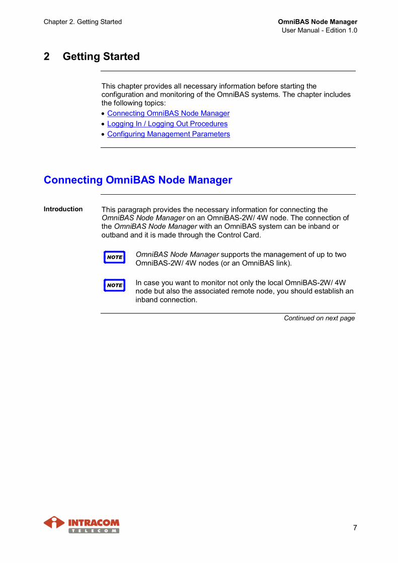
Introduction This paragraph provides the necessary information for connecting theOmniBAS Node Manager on an OmniBAS-2W/ 4W node. The connection ofthe OmniBAS Node Manager with an OmniBAS system can be inband oroutband and it is made through the Control Card.
NOTE OmniBAS Node Manager supports the management of up to twoOmniBAS-2W/ 4W nodes (or an OmniBAS link).
NOTE In case you want to monitor not only the local OmniBAS-2W/ 4Wnode but also the associated remote node, you should establish aninband connection.
Continued on next page

OmniBAS Node ManagerUser Manual - Edition 1.0
Chapter 2. Getting Started
8
Connecting OmniBAS Node Manager, Continued
Inbandmanagementconnection
The inband management connection on an OmniBAS-2W node can beimplemented through the GbE port or one of the four Fast Ethernet ports of theControl Card.The inband management connection on an OmniBAS-4W node can beimplemented through one of the two GbE ports of the Control Card.
OmniBAS-2W Inband Connection
OmniBAS-4W Inband Connection
Continued on next page
Chapter 2. Getting Started OmniBAS Node ManagerUser Manual - Edition 1.0
9
Connecting OmniBAS Node Manager, Continued
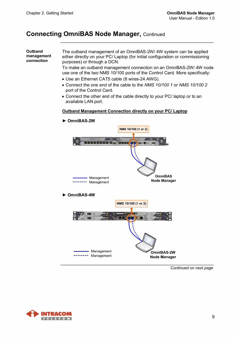
Outbandmanagementconnection
The outband management of an OmniBAS-2W/ 4W system can be appliedeither directly on your PC/ Laptop (for initial configuration or commissioningpurposes) or through a DCN.To make an outband management connection on an OmniBAS-2W/ 4W nodeuse one of the two NMS 10/100 ports of the Control Card. More specifically:· Use an Ethernet CAT5 cable (8 wires-24 AWG).· Connect the one end of the cable to the NMS 10/100 1 or NMS 10/100 2
port of the Control Card.· Connect the other end of the cable directly to your PC/ laptop or to an
available LAN port.
Outband Management Connection directly on your PC/ Laptop
► OmniBAS-2W
► OmniBAS-4W
Continued on next page
OmniBAS Node ManagerUser Manual - Edition 1.0
Chapter 2. Getting Started
10
Connecting OmniBAS Node Manager, Continued
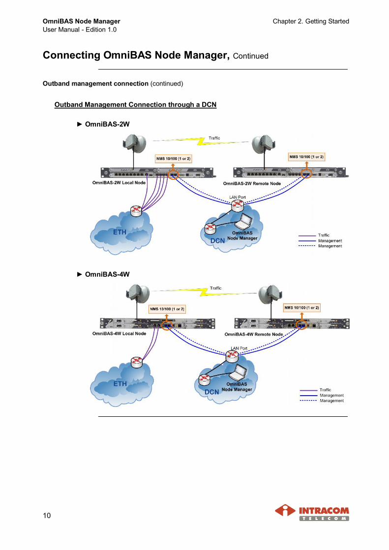
Outband management connection (continued)
Outband Management Connection through a DCN
► OmniBAS-2W
► OmniBAS-4W
Chapter 2. Getting Started OmniBAS Node ManagerUser Manual - Edition 1.0
11
Logging In / Logging Out Procedures
Introduction This paragraph describes how to:· Launch the OmniBAS Node Manager.· Log in to the OmniBAS Node Manager.· Change your login password.· Close the OmniBAS Node Manager.
Prerequisite A zip file is provided by INTACOM TELECOM for installing the OmniBAS NodeManager.
LaunchingOmniBAS NM
To launch the OmniBAS Node Manager, proceed as follows
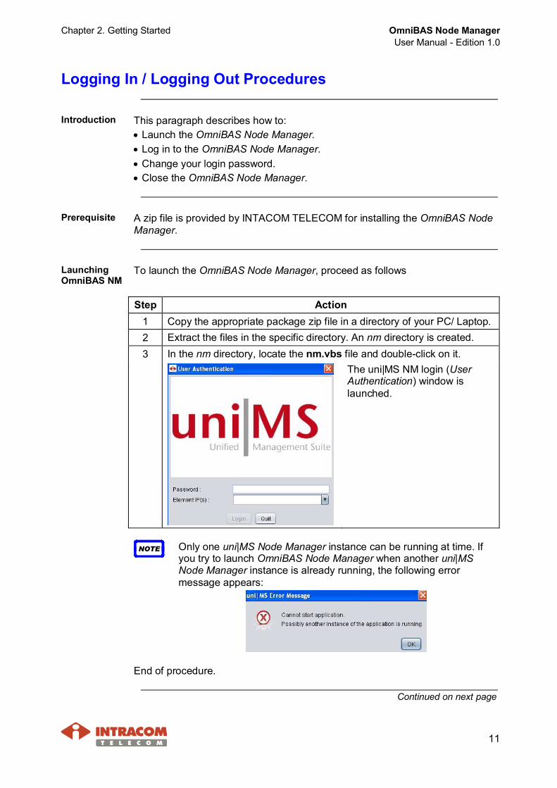
Step Action1 Copy the appropriate package zip file in a directory of your PC/ Laptop.2 Extract the files in the specific directory. An nm directory is created.3 In the nm directory, locate the nm.vbs file and double-click on it.
The uni|MS NM login (UserAuthentication) window islaunched.
NOTE Only one uni|MS Node Manager instance can be running at time. Ifyou try to launch OmniBAS Node Manager when another uni|MSNode Manager instance is already running, the following errormessage appears:
End of procedure.
Continued on next page
OmniBAS Node ManagerUser Manual - Edition 1.0
Chapter 2. Getting Started
12
Logging In / Logging Out Procedures, Continued
Log in To log in to the OmniBAS Node Manager, proceed as follows:
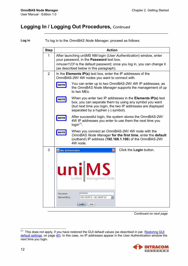
Step Action1 After launching uni|MS NM login (User Authentication) window, enter
your password, in the Password text box.nmuser123! is the default password; once you log in, you can change it(as described below in this paragraph).
2 In the Elements IP(s) text box, enter the IP addresses of theOmniBAS-2W/ 4W nodes you want to connect with.
NOTE You can enter up to two OmniBAS-2W/ 4W IP addresses, asthe OmniBAS Node Manager supports the management of upto two MEs.
NOTE When you enter two IP addresses in the Elements IP(s) textbox, you can separate them by using any symbol you want(but next time you login, the two IP addresses are displayedseparated by a hyphen (-) symbol).
NOTE After successful login, the system stores the OmniBAS-2W/4W IP addresses you enter to use them the next time youlogin(1).
NOTE When you connect an OmniBAS-2W/ 4W node with theOmniBAS Node Manager for the first time, enter the default(outband) IP address (192.168.1.100) of the OmniBAS-2W/4W node.
3 Click the Login button.
Continued on next page
(1) This does not apply, if you have restored the GUI default values (as described in par. Restoring GUIdefault settings, on page 40). In this case, no IP addresses appear in the User Authentication window thenext time you login.
Chapter 2. Getting Started OmniBAS Node ManagerUser Manual - Edition 1.0
13
Logging In / Logging Out Procedures, Continued
Log in (continued)
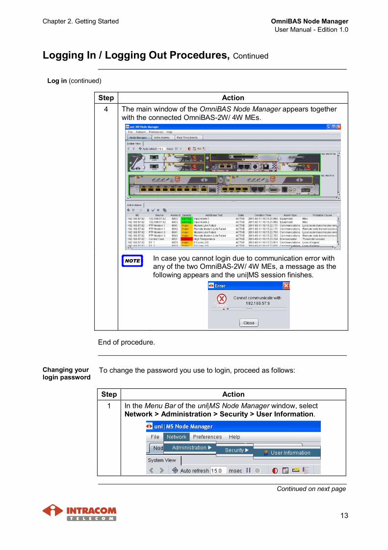
Step Action4 The main window of the OmniBAS Node Manager appears together
with the connected OmniBAS-2W/ 4W MEs.
NOTE In case you cannot login due to communication error withany of the two OmniBAS-2W/ 4W MEs, a message as thefollowing appears and the uni|MS session finishes.
End of procedure.
Changing yourlogin password
To change the password you use to login, proceed as follows:
Step Action1 In the Menu Bar of the uni|MS Node Manager window, select
Network > Administration > Security > User Information.
Continued on next page

OmniBAS Node ManagerUser Manual - Edition 1.0
Chapter 2. Getting Started
14
Logging In / Logging Out Procedures, Continued
Changing your login password (continued)
Step Action2 In the Password text box, type the
new password (eight characters atleast, both, letters and numbers).
3 Type again the new password for confirmation in the Re-enterpassword text box.
4 Click Ok to apply the password change.
End of procedure.
Log out To exit the OmniBAS Node Manager, proceed as follows:
NOTE Before you exit the application, make sure you have saved theconfiguration settings of the connected OmniBAS-2W MEs (seepar. Saving OmniBAS-2W/ 4W ME Configuration, on page 167).
Step Action1 In the Menu Bar of the uni|MS Node Manager window, select File >
Exit (or click the button in the upper-right corner of the window).
2 In the confirmationwindow that appears,click Yes
End of procedure.
Chapter 2. Getting Started OmniBAS Node ManagerUser Manual - Edition 1.0
15
Configuring Management Parameters
Introduction This paragraph describes how to:· Set the inband IP address of an OmniBAS-2W/ 4W ME.· Change the management VLAN of an OmniBAS-2W/ 4W ME.· Change the outband IP address of an OmniBAS-2W/ 4W ME.
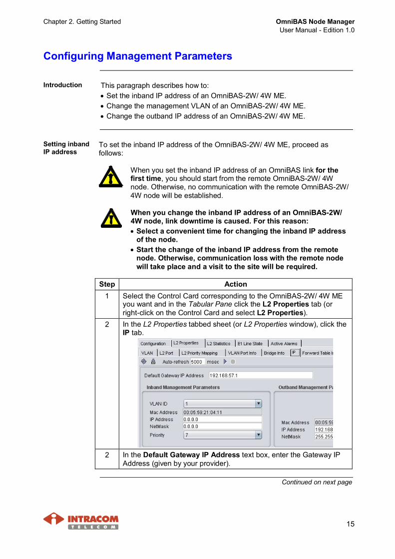
Setting inbandIP address
To set the inband IP address of the OmniBAS-2W/ 4W ME, proceed asfollows:
When you set the inband IP address of an OmniBAS link for thefirst time, you should start from the remote OmniBAS-2W/ 4Wnode. Otherwise, no communication with the remote OmniBAS-2W/4W node will be established.
When you change the inband IP address of an OmniBAS-2W/4W node, link downtime is caused. For this reason:· Select a convenient time for changing the inband IP address
of the node.· Start the change of the inband IP address from the remote
node. Otherwise, communication loss with the remote nodewill take place and a visit to the site will be required.
Step Action1 Select the Control Card corresponding to the OmniBAS-2W/ 4W ME
you want and in the Tabular Pane click the L2 Properties tab (orright-click on the Control Card and select L2 Properties).
2 In the L2 Properties tabbed sheet (or L2 Properties window), click theIP tab.
2 In the Default Gateway IP Address text box, enter the Gateway IPAddress (given by your provider).
Continued on next page
OmniBAS Node ManagerUser Manual - Edition 1.0
Chapter 2. Getting Started
16
Configuring Management Parameters, Continued
Setting inband IP address (continued)
Step Action3 Type the inband management IP address (given by your provider) in
the IP Address text box (of the Inband Management Parametersgroup box).
4 Type the inband netmask (given by your provider) in the NetMask textbox (of the Inband Management Parameters group box).
NOTE The MAC Address text box (of the Inband ManagementParameters group box) displays the MAC address of theOmniBAS-2W/ 4W physical interface through which theinband connection with the OmniBAS Node Manager ismade.
5 Click the button to apply the inband management settings.
End of procedure.
Changing themanagementVLAN
To change the management VLAN of an OmniBAS-2W/ 4W ME with anexisting one(1), proceed as follows:
NOTE The default management VLAN of the OmniBAS-2W/ 4W MEs is theVLAN with ID=1. It is recommended to change the defaultmanagement VLAN associating to a new one.
Step Action1 Select the Control Card corresponding to the OmniBAS-2W/ 4W ME
you want and in the Tabular Pane click the L2 Properties tab (orright-click on the Control Card and select L2 Properties).
2 In the L2 Properties tabbed sheet (or L2 Properties window), click theVLAN Port tab. In the VLAN Port tabbed sheet, associate the VLANyou want to define as management VLAN to all L2 modem portscorresponding(2) to the connected Modem Cards (see par. AssociatingVLANs with L2 Port, on page 152).
The management VLAN should be associated to all L2modem ports of the OmniBAS-2W/ 4W ME. Otherwise,communication loss with the remote node will take placeand a visit to the site will be required.
Continued on next page
(1) To create a VLAN, see par. Creating a VLAN, on page 147.(2) For example, in case of the OmniBAS-2W 1+0 configuration, you do not need to associate the VLANto both L2 modem ports but only to the port corresponding to the connected Modem Card.
Chapter 2. Getting Started OmniBAS Node ManagerUser Manual - Edition 1.0
17
Configuring Management Parameters, Continued
Changing the management VLAN (continued)
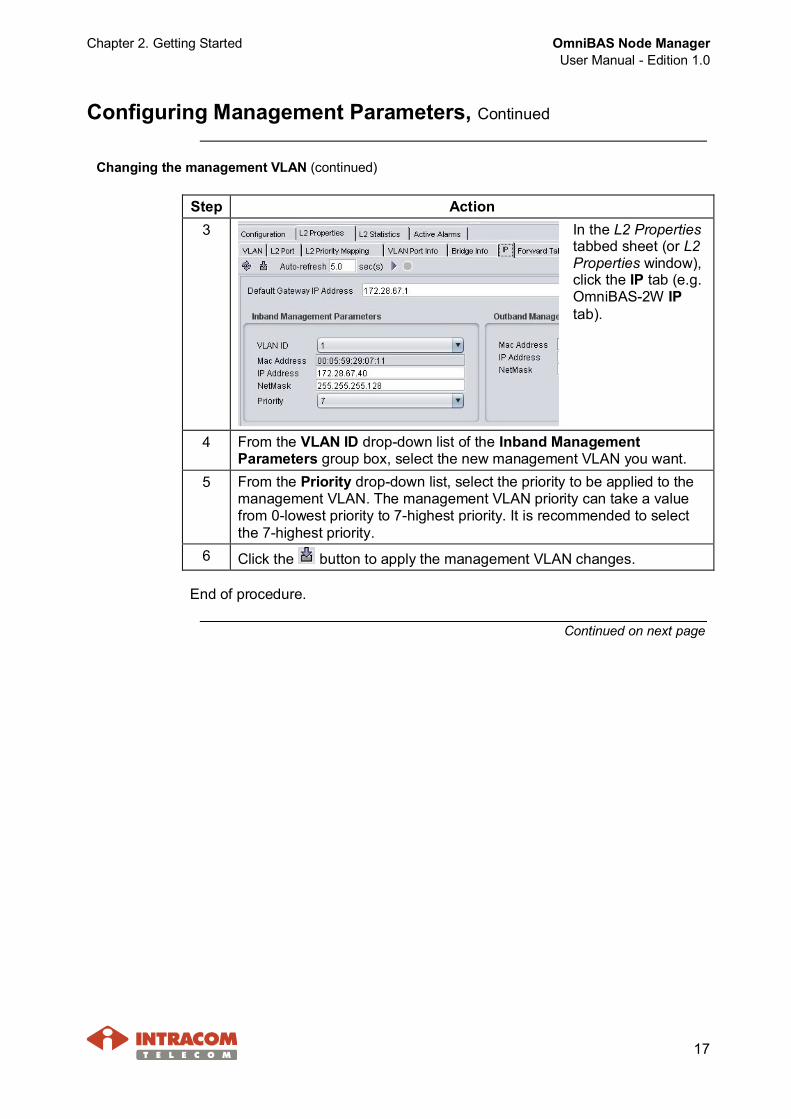
Step Action3 In the L2 Properties
tabbed sheet (or L2Properties window),click the IP tab (e.g.OmniBAS-2W IPtab).
4 From the VLAN ID drop-down list of the Inband ManagementParameters group box, select the new management VLAN you want.
5 From the Priority drop-down list, select the priority to be applied to themanagement VLAN. The management VLAN priority can take a valuefrom 0-lowest priority to 7-highest priority. It is recommended to selectthe 7-highest priority.
6 Click the button to apply the management VLAN changes.
End of procedure.
Continued on next page
OmniBAS Node ManagerUser Manual - Edition 1.0
Chapter 2. Getting Started
18
Configuring Management Parameters, Continued
Changingoutband IPaddress
To change the outband IP address of an OmniBAS-2W/ 4W ME, proceed asfollows:
Step Action1 Select the Control Card corresponding to the OmniBAS-2W/ 4W ME you
want and in the Tabular Pane click the L2 Properties tab (or right-clickon the Control Card and select L2 Properties).
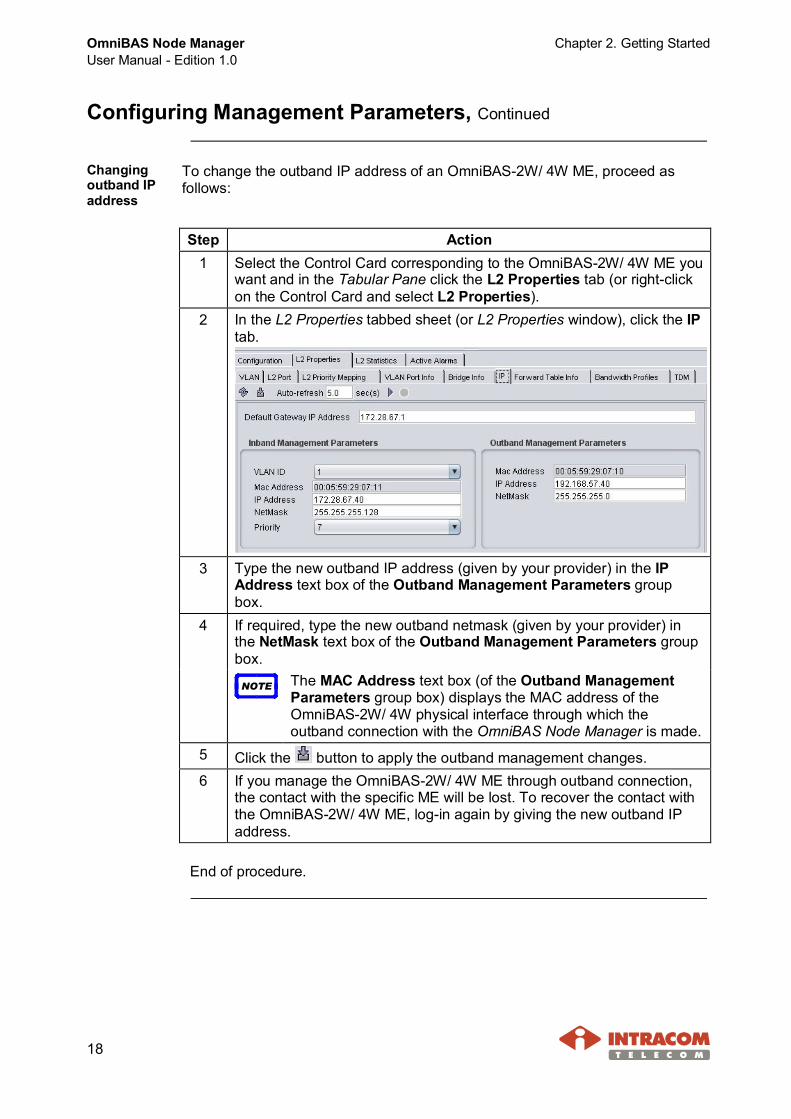
2 In the L2 Properties tabbed sheet (or L2 Properties window), click the IPtab.
3 Type the new outband IP address (given by your provider) in the IPAddress text box of the Outband Management Parameters groupbox.
4 If required, type the new outband netmask (given by your provider) inthe NetMask text box of the Outband Management Parameters groupbox.
NOTE The MAC Address text box (of the Outband ManagementParameters group box) displays the MAC address of theOmniBAS-2W/ 4W physical interface through which theoutband connection with the OmniBAS Node Manager is made.
5 Click the button to apply the outband management changes.6 If you manage the OmniBAS-2W/ 4W ME through outband connection,
the contact with the specific ME will be lost. To recover the contact withthe OmniBAS-2W/ 4W ME, log-in again by giving the new outband IPaddress.
End of procedure.
Chapter 3. GUI Overview OmniBAS Node ManagerUser Manual - Edition 1.0
19
3 GUI Overview
The scope of this chapter is to get you familiar with the Graphical User Interface(GUI) of the OmniBAS Node Manager. The chapter includes the following topics:· Main Window· Menu Bar· Graphical View - OmniBAS-2W/ 4W MEs Representation· Graphical View Indications· Refresh Processes· Main Buttons Description· GUI Customization· Active Alarms & Real Time Events Lists
Main Window
Introduction This paragraph represents the main window of the OmniBAS Node Manager.
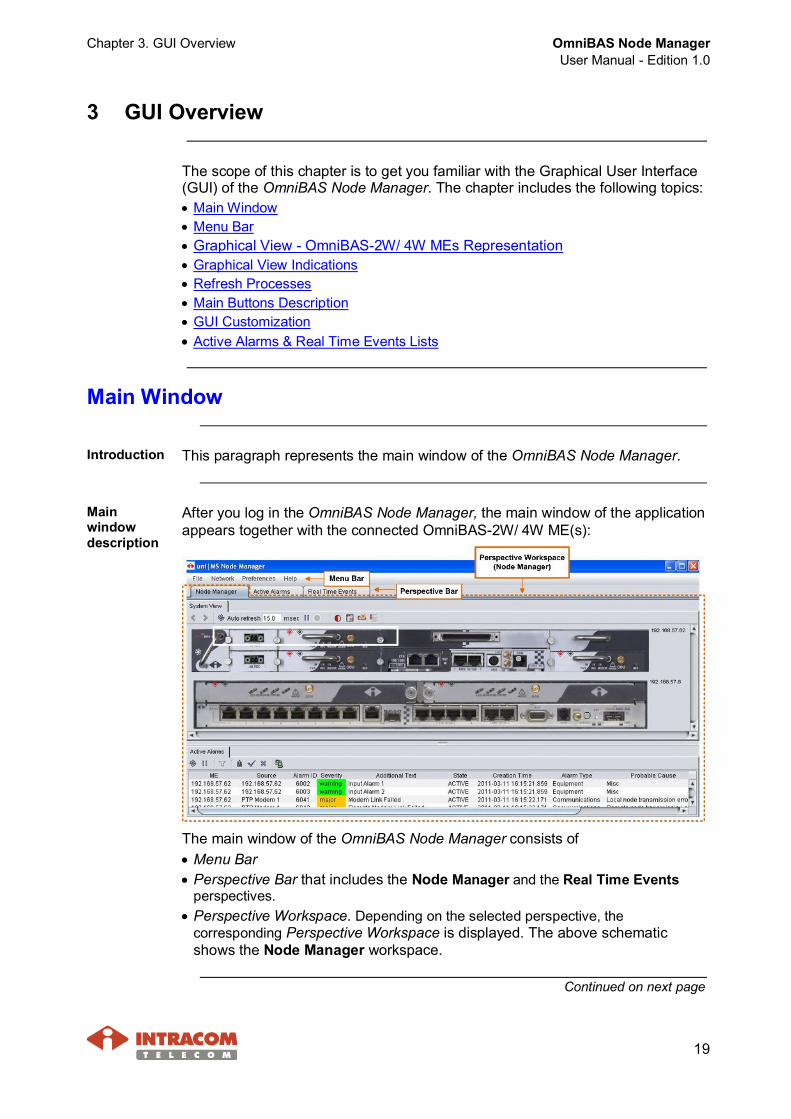
Mainwindowdescription
After you log in the OmniBAS Node Manager, the main window of the applicationappears together with the connected OmniBAS-2W/ 4W ME(s):
The main window of the OmniBAS Node Manager consists of· Menu Bar· Perspective Bar that includes the Node Manager and the Real Time Events
perspectives.· Perspective Workspace. Depending on the selected perspective, the
corresponding Perspective Workspace is displayed. The above schematicshows the Node Manager workspace.
Continued on next page

OmniBAS Node ManagerUser Manual - Edition 1.0
Chapter 3. GUI Overview
20
Main Window, Continued
Real TimeEventsPerspective
When you select the Real Time Events perspective, the corresponding RealTime Events workspace appears listing all the events generated for theconnected OmniBAS-2W ME(s) since the launching of the OmniBAS NodeManager. From now on, the Real Time Events perspective will be mentionedas Real Time Events list. For more information about Real Time Events list,see Ch. 14. Monitoring Real Time Events (page 250).
ActiveAlarmsPerspective
When you select the Active Alarms perspective, the corresponding ActiveAlarms workspace appears listing all the alarms generated by the connectedOmniBAS equipment since the launching of the OmniBAS Node Manager.From now on, the Active Alarms perspective will be mentioned as Real TimeEvents list. For more information about Real Time Events list, see Ch. 13 FaultManagement (page 239).
Continued on next page
Chapter 3. GUI Overview OmniBAS Node ManagerUser Manual - Edition 1.0
21
Main Window, Continued
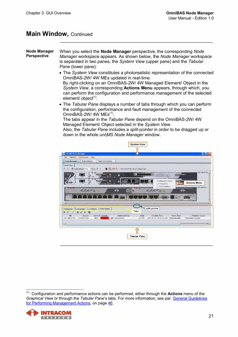
Node ManagerPerspective
When you select the Node Manager perspective, the corresponding NodeManager workspace appears. As shown below, the Node Manager workspaceis separated in two panes, the System View (upper pane) and the TabularPane (lower pane):· The System View constitutes a photorealistic representation of the connected
OmniBAS-2W/ 4W MEs updated in real-time.By right-clicking on an OmniBAS-2W/ 4W Managed Element/ Object in theSystem View, a corresponding Actions Menu appears, through which, youcan perform the configuration and performance management of the selectedelement/ object(1).
· The Tabular Pane displays a number of tabs through which you can performthe configuration, performance and fault management of the connectedOmniBAS-2W/ 4W MEs(1).The tabs appear in the Tabular Pane depend on the OmniBAS-2W/ 4WManaged Element/ Object selected in the System View.Also, the Tabular Pane includes a split-pointer in order to be dragged up ordown in the whole uni|MS Node Manager window.
(1) Configuration and performance actions can be performed, either through the Actions menu of theGraphical View or through the Tabular Pane’s tabs. For more information, see par. General Guidelinesfor Performing Management Actions, on page 46.

OmniBAS Node ManagerUser Manual - Edition 1.0
Chapter 3. GUI Overview
22
Menu Bar
The Menu Bar of the uni|MS Node Manager consists of four menus, eachdescribed in the following table.
Menu Sub-Menu Description Reference
File Exit To exit the OmniBAS NodeManager application.
Par. Log out (page 14)
Network Administration To change the loginpassword.
Par. Changing your loginpassword, on page 13.
SetPreferences
To customize the GUI of theOmniBAS Node Manager.
Preferences
ResetPreferences
To restore the GUI defaultsettings of the OmniBASNode Manager.
Par. GUI Customization(page 35)
Help About To check the release of theOmniBAS Node Manager.
Par. Checking OmniBASNode Manager Release(page 41)
Chapter 3. GUI Overview OmniBAS Node ManagerUser Manual - Edition 1.0
23
Graphical View - OmniBAS-2W/ 4W MEs Representation
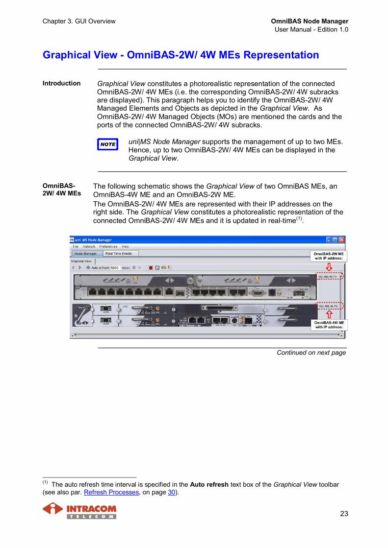
Introduction Graphical View constitutes a photorealistic representation of the connectedOmniBAS-2W/ 4W MEs (i.e. the corresponding OmniBAS-2W/ 4W subracksare displayed). This paragraph helps you to identify the OmniBAS-2W/ 4WManaged Elements and Objects as depicted in the Graphical View. AsOmniBAS-2W/ 4W Managed Objects (MOs) are mentioned the cards and theports of the connected OmniBAS-2W/ 4W subracks.
NOTE uni|MS Node Manager supports the management of up to two MEs.Hence, up to two OmniBAS-2W/ 4W MEs can be displayed in theGraphical View.
OmniBAS-2W/ 4W MEs
The following schematic shows the Graphical View of two OmniBAS MEs, anOmniBAS-4W ME and an OmniBAS-2W ME.The OmniBAS-2W/ 4W MEs are represented with their IP addresses on theright side. The Graphical View constitutes a photorealistic representation of theconnected OmniBAS-2W/ 4W MEs and it is updated in real-time(1).
Continued on next page
(1) The auto refresh time interval is specified in the Auto refresh text box of the Graphical View toolbar(see also par. Refresh Processes, on page 30).
OmniBAS Node ManagerUser Manual - Edition 1.0
Chapter 3. GUI Overview
24
Graphical View - OmniBAS-2W/ 4W MEs Representation,Continued
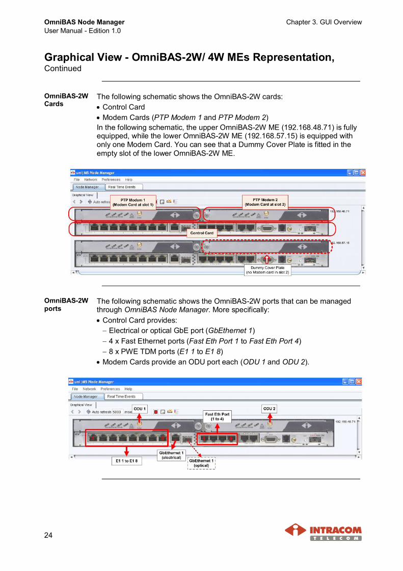
OmniBAS-2WCards
The following schematic shows the OmniBAS-2W cards:· Control Card· Modem Cards (PTP Modem 1 and PTP Modem 2)In the following schematic, the upper OmniBAS-2W ME (192.168.48.71) is fullyequipped, while the lower OmniBAS-2W ME (192.168.57.15) is equipped withonly one Modem Card. You can see that a Dummy Cover Plate is fitted in theempty slot of the lower OmniBAS-2W ME.
OmniBAS-2Wports
The following schematic shows the OmniBAS-2W ports that can be managedthrough OmniBAS Node Manager. More specifically:· Control Card provides:- Electrical or optical GbE port (GbEthernet 1)- 4 x Fast Ethernet ports (Fast Eth Port 1 to Fast Eth Port 4)- 8 x PWE TDM ports (E1 1 to E1 8)
· Modem Cards provide an ODU port each (ODU 1 and ODU 2).
Chapter 3. GUI Overview OmniBAS Node ManagerUser Manual - Edition 1.0
25
Graphical View - OmniBAS-2W/ 4W MEs Representation,Continued
OmniBAS-4WCards/ Units
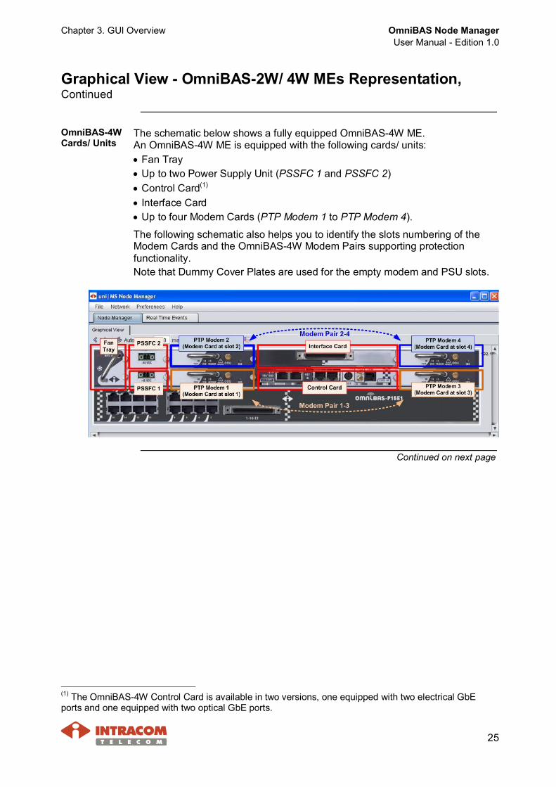
The schematic below shows a fully equipped OmniBAS-4W ME.An OmniBAS-4W ME is equipped with the following cards/ units:· Fan Tray· Up to two Power Supply Unit (PSSFC 1 and PSSFC 2)· Control Card(1)
· Interface Card· Up to four Modem Cards (PTP Modem 1 to PTP Modem 4).
The following schematic also helps you to identify the slots numbering of theModem Cards and the OmniBAS-4W Modem Pairs supporting protectionfunctionality.Note that Dummy Cover Plates are used for the empty modem and PSU slots.
Continued on next page
(1) The OmniBAS-4W Control Card is available in two versions, one equipped with two electrical GbEports and one equipped with two optical GbE ports.
OmniBAS Node ManagerUser Manual - Edition 1.0
Chapter 3. GUI Overview
26
Graphical View - OmniBAS-2W/ 4W MEs Representation,Continued
OmniBAS-4Wports
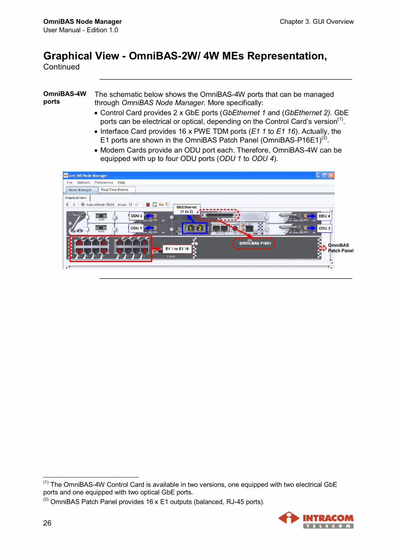
The schematic below shows the OmniBAS-4W ports that can be managedthrough OmniBAS Node Manager. More specifically:· Control Card provides 2 x GbE ports (GbEthernet 1 and (GbEthernet 2). GbE
ports can be electrical or optical, depending on the Control Card’s version(1).· Interface Card provides 16 x PWE TDM ports (E1 1 to E1 16). Actually, the
E1 ports are shown in the OmniBAS Patch Panel (OmniBAS-P16E1)(2).· Modem Cards provide an ODU port each. Therefore, OmniBAS-4W can be
equipped with up to four ODU ports (ODU 1 to ODU 4).
(1) The OmniBAS-4W Control Card is available in two versions, one equipped with two electrical GbEports and one equipped with two optical GbE ports.(2) OmniBAS Patch Panel provides 16 x Ε1 outputs (balanced, RJ-45 ports).
Chapter 3. GUI Overview OmniBAS Node ManagerUser Manual - Edition 1.0
27
Graphical View Indications
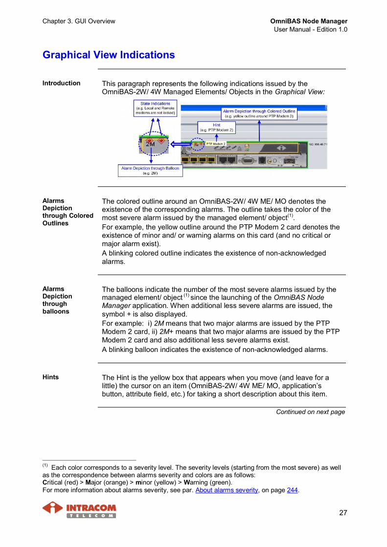
Introduction This paragraph represents the following indications issued by theOmniBAS-2W/ 4W Managed Elements/ Objects in the Graphical View:
AlarmsDepictionthrough ColoredOutlines
The colored outline around an OmniBAS-2W/ 4W ME/ MO denotes theexistence of the corresponding alarms. The outline takes the color of themost severe alarm issued by the managed element/ object(1).For example, the yellow outline around the PTP Modem 2 card denotes theexistence of minor and/ or warning alarms on this card (and no critical ormajor alarm exist).A blinking colored outline indicates the existence of non-acknowledgedalarms.
AlarmsDepictionthroughballoons
The balloons indicate the number of the most severe alarms issued by themanaged element/ object (1) since the launching of the OmniBAS NodeManager application. When additional less severe alarms are issued, thesymbol + is also displayed.For example: i) 2M means that two major alarms are issued by the PTPModem 2 card, ii) 2M+ means that two major alarms are issued by the PTPModem 2 card and also additional less severe alarms exist.A blinking balloon indicates the existence of non-acknowledged alarms.
Hints The Hint is the yellow box that appears when you move (and leave for alittle) the cursor on an item (OmniBAS-2W/ 4W ME/ MO, application’sbutton, attribute field, etc.) for taking a short description about this item.
Continued on next page
(1) Each color corresponds to a severity level. The severity levels (starting from the most severe) as wellas the correspondence between alarms severity and colors are as follows:Critical (red) > Major (orange) > minor (yellow) > Warning (green).For more information about alarms severity, see par. About alarms severity, on page 244.
OmniBAS Node ManagerUser Manual - Edition 1.0
Chapter 3. GUI Overview
28
Graphical View Indications, Continued
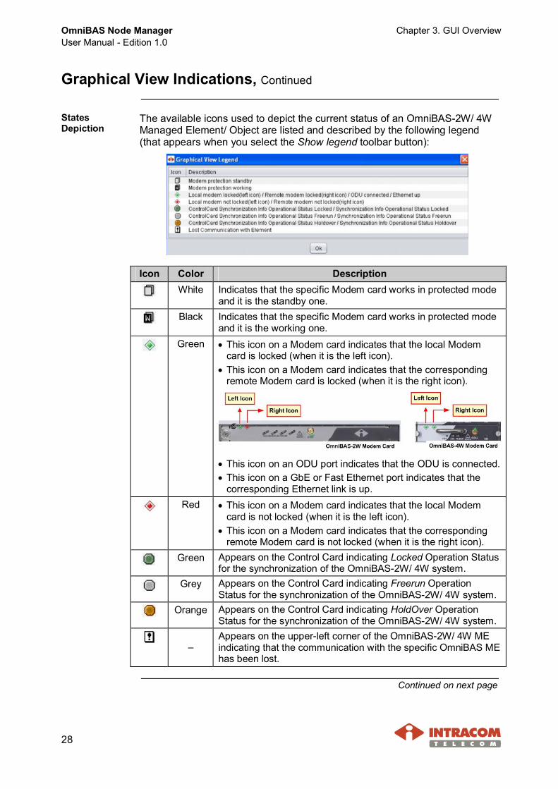
StatesDepiction
The available icons used to depict the current status of an OmniBAS-2W/ 4WManaged Element/ Object are listed and described by the following legend(that appears when you select the Show legend toolbar button):
Icon Color DescriptionWhite Indicates that the specific Modem card works in protected mode
and it is the standby one.Black Indicates that the specific Modem card works in protected mode
and it is the working one.Green · This icon on a Modem card indicates that the local Modem
card is locked (when it is the left icon).· This icon on a Modem card indicates that the corresponding
remote Modem card is locked (when it is the right icon).
· This icon on an ODU port indicates that the ODU is connected.· This icon on a GbE or Fast Ethernet port indicates that the
corresponding Ethernet link is up.Red · This icon on a Modem card indicates that the local Modem
card is not locked (when it is the left icon).· This icon on a Modem card indicates that the corresponding
remote Modem card is not locked (when it is the right icon).Green Appears on the Control Card indicating Locked Operation Status
for the synchronization of the OmniBAS-2W/ 4W system.Grey Appears on the Control Card indicating Freerun Operation
Status for the synchronization of the OmniBAS-2W/ 4W system.Orange Appears on the Control Card indicating HoldOver Operation
Status for the synchronization of the OmniBAS-2W/ 4W system.
–Appears on the upper-left corner of the OmniBAS-2W/ 4W MEindicating that the communication with the specific OmniBAS MEhas been lost.
Continued on next page

Chapter 3. GUI Overview OmniBAS Node ManagerUser Manual - Edition 1.0
29
Graphical View Indications, Continued
Enabling/disablingindicationsappearance
You can enable or disable the appearance of any graphical view indicationthrough the Set Preferences action described in par. Customizing GraphicalView (on page 36).Also, you can enable or disable the appearance of any graphical viewindication by using the corresponding buttons on the Graphical View’stoolbar (see par. Graphical View, on page 33).

OmniBAS Node ManagerUser Manual - Edition 1.0
Chapter 3. GUI Overview
30
Refresh Processes
Introduction OmniBAS Node Manager provides the following refresh processes:· Refreshing of Graphical View (auto or manual)· Refreshing of a selected tabbed sheet (auto or manual). A selected tabbed
is shown below:
Continued on next page
Chapter 3. GUI Overview OmniBAS Node ManagerUser Manual - Edition 1.0
31
Refresh Processes, Continued
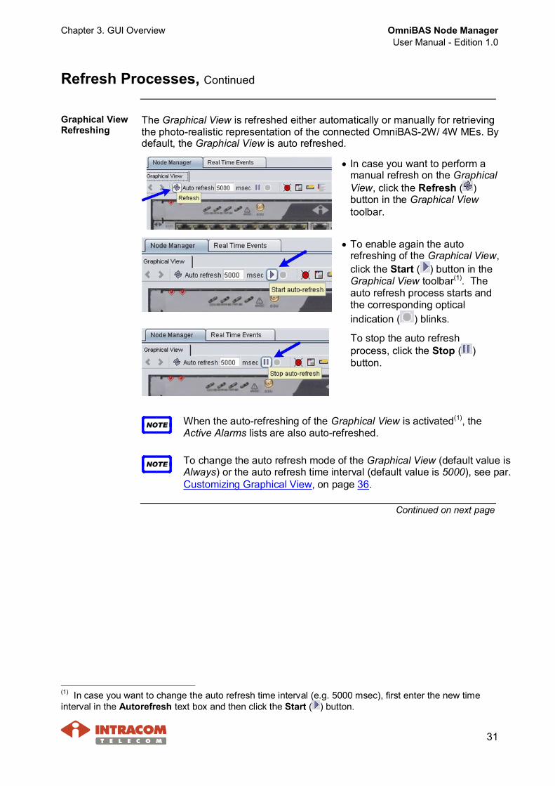
Graphical ViewRefreshing
The Graphical View is refreshed either automatically or manually for retrievingthe photo-realistic representation of the connected OmniBAS-2W/ 4W MEs. Bydefault, the Graphical View is auto refreshed.
· In case you want to perform amanual refresh on the GraphicalView, click the Refresh ( )button in the Graphical Viewtoolbar.
· To enable again the autorefreshing of the Graphical View,click the Start ( ) button in theGraphical View toolbar(1). Theauto refresh process starts andthe corresponding opticalindication ( ) blinks.
To stop the auto refreshprocess, click the Stop ( )button.
NOTE When the auto-refreshing of the Graphical View is activated(1), theActive Alarms lists are also auto-refreshed.
NOTE To change the auto refresh mode of the Graphical View (default value isAlways) or the auto refresh time interval (default value is 5000), see par.Customizing Graphical View, on page 36.
Continued on next page
(1) In case you want to change the auto refresh time interval (e.g. 5000 msec), first enter the new timeinterval in the Autorefresh text box and then click the Start ( ) button.
OmniBAS Node ManagerUser Manual - Edition 1.0
Chapter 3. GUI Overview
32
Refresh Processes, Continued
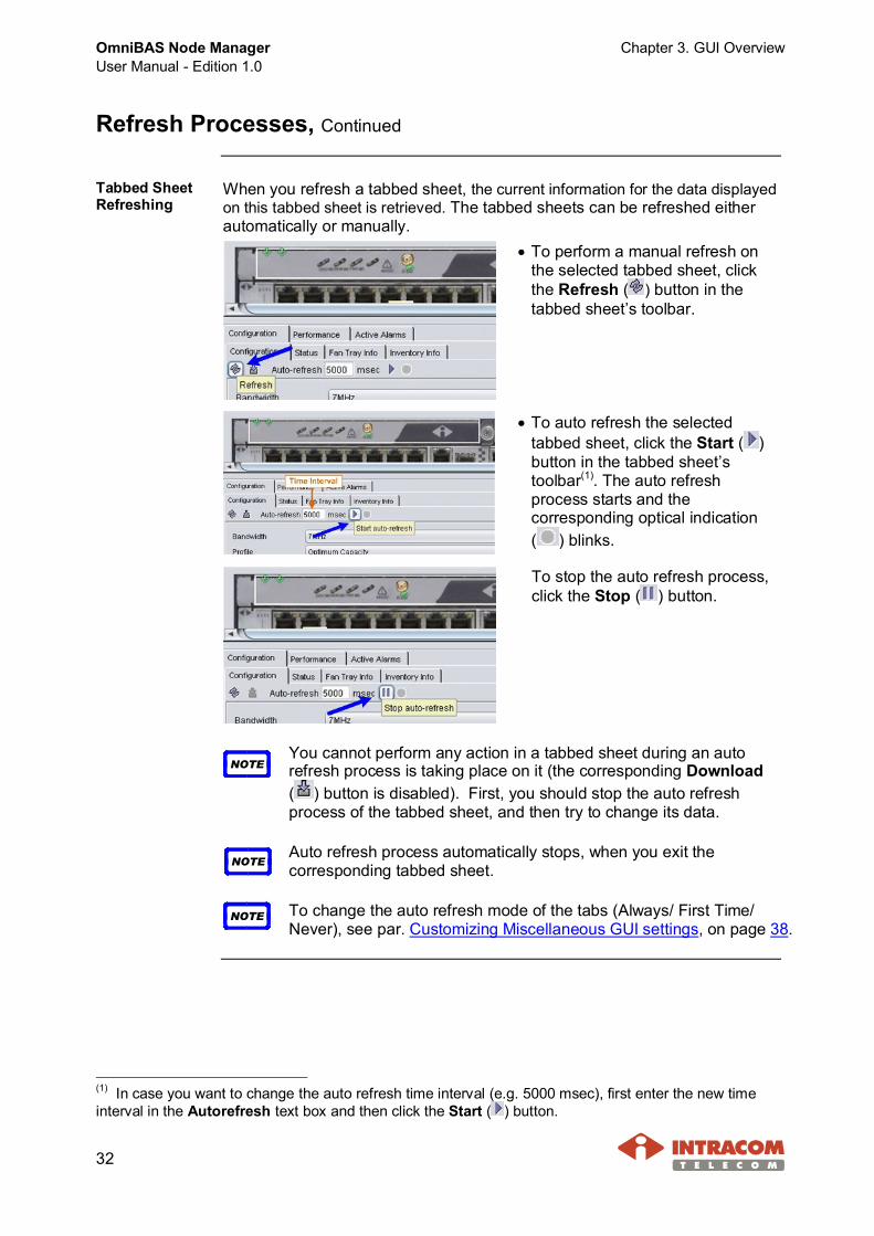
Tabbed SheetRefreshing
When you refresh a tabbed sheet, the current information for the data displayedon this tabbed sheet is retrieved. The tabbed sheets can be refreshed eitherautomatically or manually.
· To perform a manual refresh onthe selected tabbed sheet, clickthe Refresh ( ) button in thetabbed sheet’s toolbar.
· To auto refresh the selectedtabbed sheet, click the Start ( )button in the tabbed sheet’stoolbar(1). The auto refreshprocess starts and thecorresponding optical indication( ) blinks.
To stop the auto refresh process,click the Stop ( ) button.
NOTEYou cannot perform any action in a tabbed sheet during an autorefresh process is taking place on it (the corresponding Download( ) button is disabled). First, you should stop the auto refreshprocess of the tabbed sheet, and then try to change its data.
NOTEAuto refresh process automatically stops, when you exit thecorresponding tabbed sheet.
NOTE To change the auto refresh mode of the tabs (Always/ First Time/Never), see par. Customizing Miscellaneous GUI settings, on page 38.
(1) In case you want to change the auto refresh time interval (e.g. 5000 msec), first enter the new timeinterval in the Autorefresh text box and then click the Start ( ) button.
Chapter 3. GUI Overview OmniBAS Node ManagerUser Manual - Edition 1.0
33
Main Buttons Description
Introduction This paragraph describes the buttons included in the Graphical View and inthe various tabbed sheets. For the description of the buttons concerning therefresh processes, see par. Refresh Processes, on page 30.
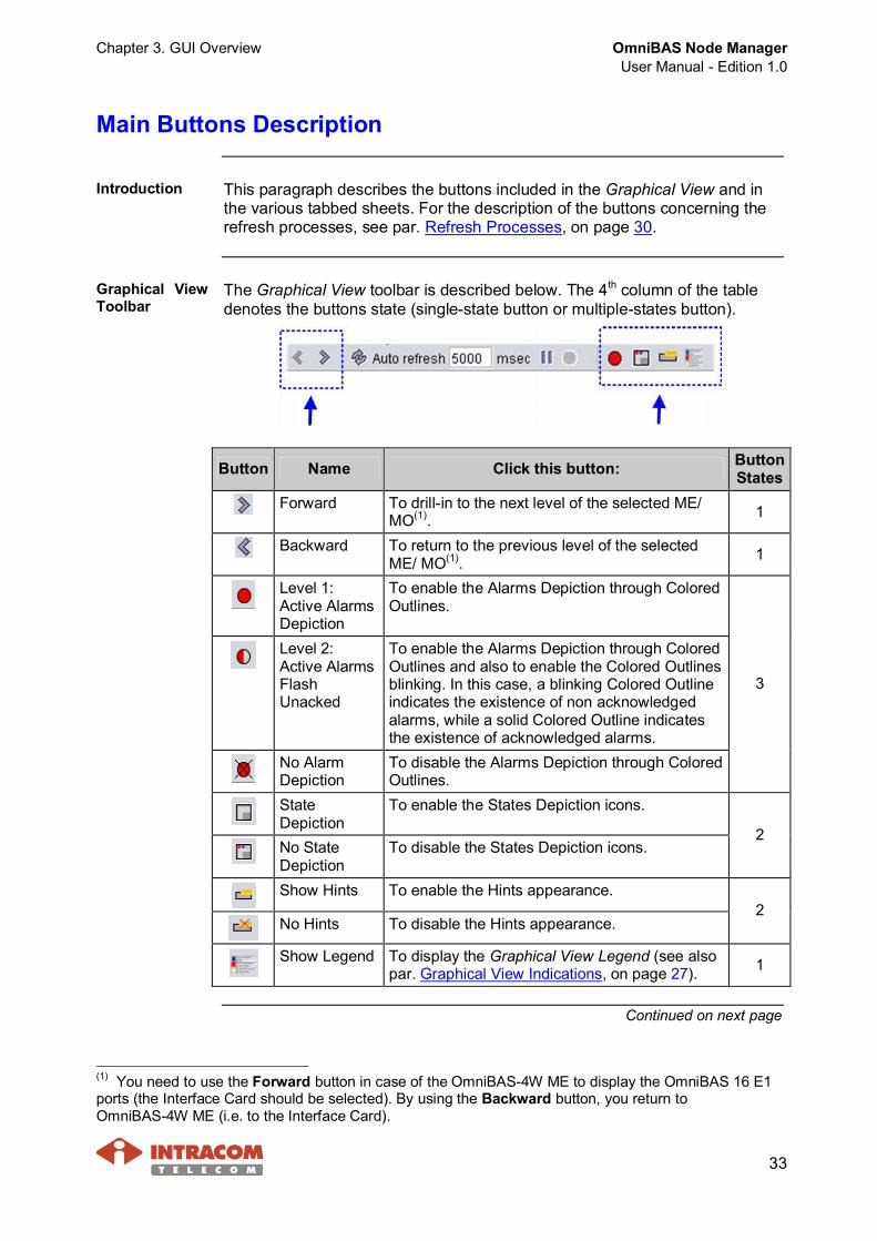
Graphical ViewToolbar
The Graphical View toolbar is described below. The 4th column of the tabledenotes the buttons state (single-state button or multiple-states button).
Button Name Click this button: ButtonStates
Forward To drill-in to the next level of the selected ME/MO(1). 1
Backward To return to the previous level of the selectedME/ MO(1). 1
Level 1:Active AlarmsDepiction
To enable the Alarms Depiction through ColoredOutlines.
Level 2:Active AlarmsFlashUnacked
To enable the Alarms Depiction through ColoredOutlines and also to enable the Colored Outlinesblinking. In this case, a blinking Colored Outlineindicates the existence of non acknowledgedalarms, while a solid Colored Outline indicatesthe existence of acknowledged alarms.
No AlarmDepiction
To disable the Alarms Depiction through ColoredOutlines.
3
StateDepiction
To enable the States Depiction icons.
No StateDepiction
To disable the States Depiction icons.2
Show Hints To enable the Hints appearance.
No Hints To disable the Hints appearance.2
Show Legend To display the Graphical View Legend (see alsopar. Graphical View Indications, on page 27). 1
Continued on next page
(1) You need to use the Forward button in case of the OmniBAS-4W ME to display the OmniBAS 16 E1ports (the Interface Card should be selected). By using the Backward button, you return toOmniBAS-4W ME (i.e. to the Interface Card).
OmniBAS Node ManagerUser Manual - Edition 1.0
Chapter 3. GUI Overview
34
Main Buttons Description, Continued
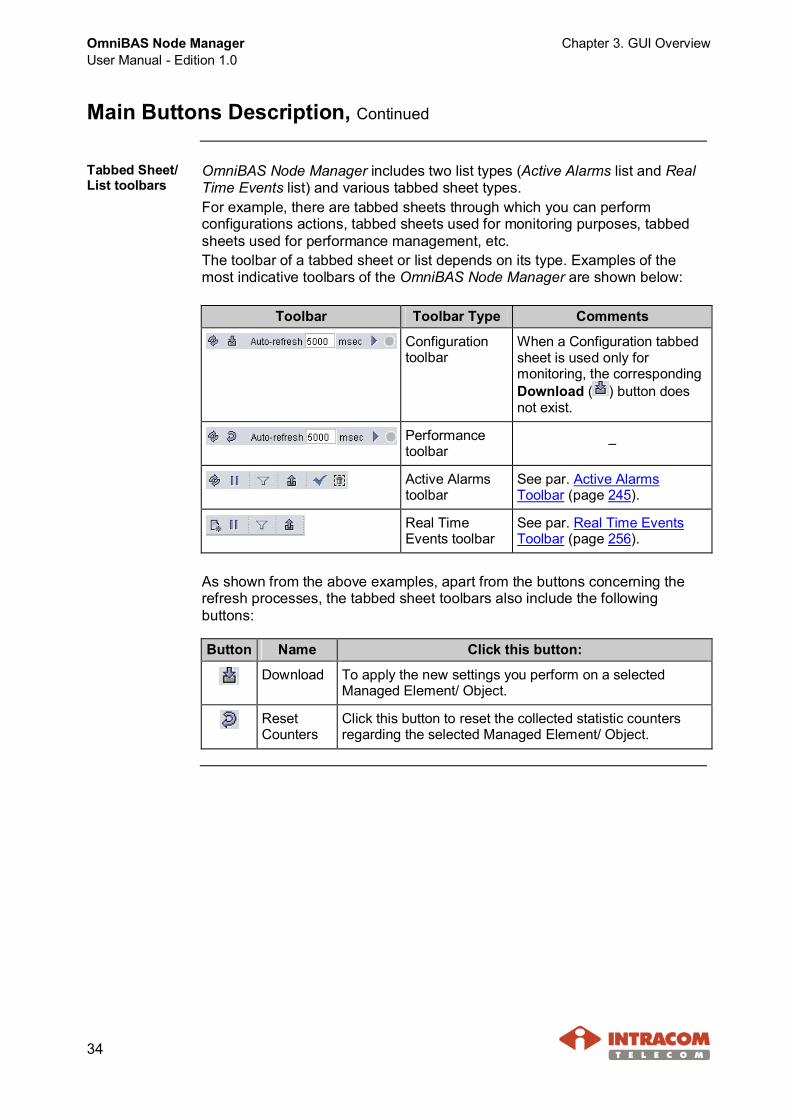
Tabbed Sheet/List toolbars
OmniBAS Node Manager includes two list types (Active Alarms list and RealTime Events list) and various tabbed sheet types.For example, there are tabbed sheets through which you can performconfigurations actions, tabbed sheets used for monitoring purposes, tabbedsheets used for performance management, etc.The toolbar of a tabbed sheet or list depends on its type. Examples of themost indicative toolbars of the OmniBAS Node Manager are shown below:
Toolbar Toolbar Type Comments
Configurationtoolbar
When a Configuration tabbedsheet is used only formonitoring, the correspondingDownload ( ) button doesnot exist.
Performancetoolbar –
Active Alarmstoolbar
See par. Active AlarmsToolbar (page 245).
Real TimeEvents toolbar
See par. Real Time EventsToolbar (page 256).
As shown from the above examples, apart from the buttons concerning therefresh processes, the tabbed sheet toolbars also include the followingbuttons:
Button Name Click this button:
Download To apply the new settings you perform on a selectedManaged Element/ Object.
ResetCounters
Click this button to reset the collected statistic countersregarding the selected Managed Element/ Object.
Chapter 3. GUI Overview OmniBAS Node ManagerUser Manual - Edition 1.0
35
GUI Customization
Introduction This paragraph describes how to customize the GUI of the OmniBAS NodeManager and also how to restore the GUI default settings.
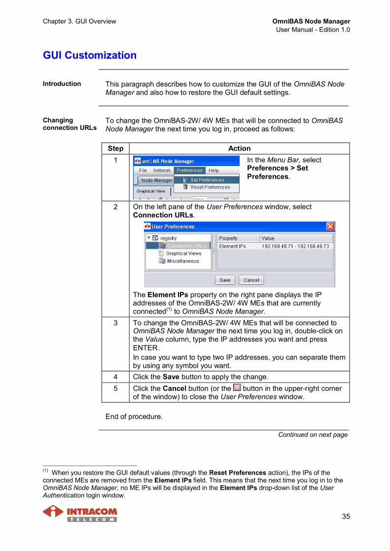
Changingconnection URLs
To change the OmniBAS-2W/ 4W MEs that will be connected to OmniBASNode Manager the next time you log in, proceed as follows:
Step Action1 In the Menu Bar, select
Preferences > SetPreferences.
2 On the left pane of the User Preferences window, selectConnection URLs.
The Element IPs property on the right pane displays the IPaddresses of the OmniBAS-2W/ 4W MEs that are currentlyconnected(1) to OmniBAS Node Manager.
3 To change the OmniBAS-2W/ 4W MEs that will be connected toOmniBAS Node Manager the next time you log in, double-click onthe Value column, type the IP addresses you want and pressENTER.In case you want to type two IP addresses, you can separate themby using any symbol you want.
4 Click the Save button to apply the change.5 Click the Cancel button (or the button in the upper-right corner
of the window) to close the User Preferences window.
End of procedure.
Continued on next page
(1) When you restore the GUI default values (through the Reset Preferences action), the IPs of theconnected MEs are removed from the Element IPs field. This means that the next time you log in to theOmniBAS Node Manager, no ME IPs will be displayed in the Element IPs drop-down list of the UserAuthentication login window.
OmniBAS Node ManagerUser Manual - Edition 1.0
Chapter 3. GUI Overview
36
GUI Customization, Continued
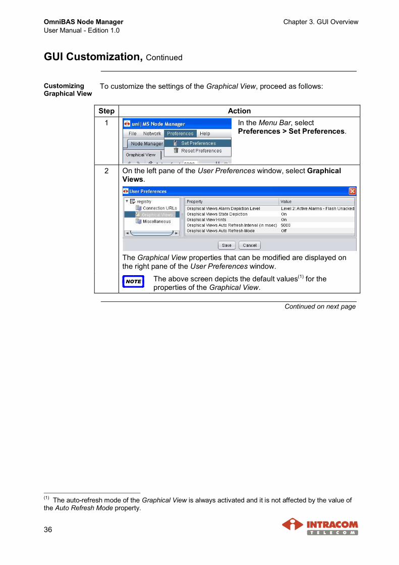
CustomizingGraphical View
To customize the settings of the Graphical View, proceed as follows:
Step Action1 In the Menu Bar, select
Preferences > Set Preferences.
2 On the left pane of the User Preferences window, select GraphicalViews.
The Graphical View properties that can be modified are displayed onthe right pane of the User Preferences window.
NOTE The above screen depicts the default values(1) for theproperties of the Graphical View.
Continued on next page
(1) The auto-refresh mode of the Graphical View is always activated and it is not affected by the value ofthe Auto Refresh Mode property.
Chapter 3. GUI Overview OmniBAS Node ManagerUser Manual - Edition 1.0
37
GUI Customization, Continued
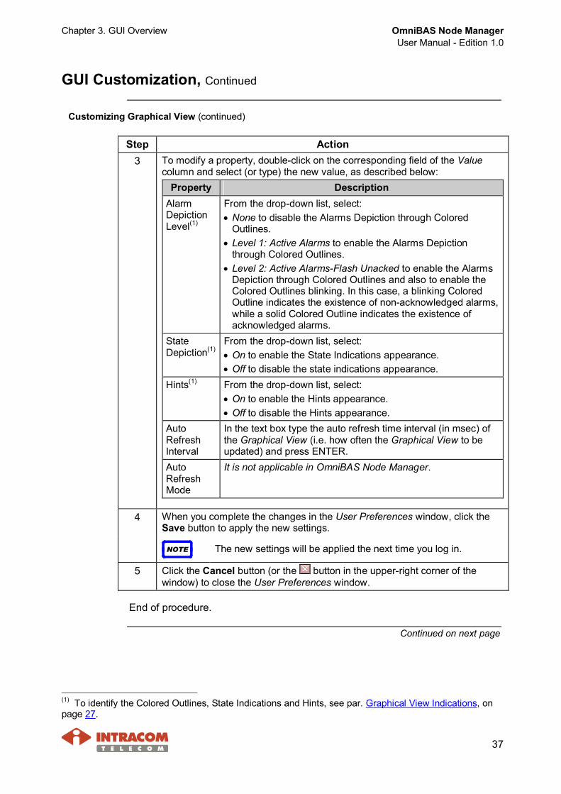
Customizing Graphical View (continued)
Step Action3 To modify a property, double-click on the corresponding field of the Value
column and select (or type) the new value, as described below:Property Description
AlarmDepictionLevel(1)
From the drop-down list, select:· None to disable the Alarms Depiction through Colored
Outlines.· Level 1: Active Alarms to enable the Alarms Depiction
through Colored Outlines.· Level 2: Active Alarms-Flash Unacked to enable the Alarms
Depiction through Colored Outlines and also to enable theColored Outlines blinking. In this case, a blinking ColoredOutline indicates the existence of non-acknowledged alarms,while a solid Colored Outline indicates the existence ofacknowledged alarms.
StateDepiction(1)
From the drop-down list, select:· On to enable the State Indications appearance.· Off to disable the state indications appearance.
Hints(1) From the drop-down list, select:· On to enable the Hints appearance.· Off to disable the Hints appearance.
AutoRefreshInterval
In the text box type the auto refresh time interval (in msec) ofthe Graphical View (i.e. how often the Graphical View to beupdated) and press ENTER.
AutoRefreshMode
It is not applicable in OmniBAS Node Manager.
4 When you complete the changes in the User Preferences window, click theSave button to apply the new settings.
NOTE The new settings will be applied the next time you log in.
5 Click the Cancel button (or the button in the upper-right corner of thewindow) to close the User Preferences window.
End of procedure.
Continued on next page
(1) To identify the Colored Outlines, State Indications and Hints, see par. Graphical View Indications, onpage 27.

OmniBAS Node ManagerUser Manual - Edition 1.0
Chapter 3. GUI Overview
38
GUI Customization, Continued
CustomizingMiscellaneousGUI settings
To customize the miscellaneous GUI settings of the OmniBAS NodeManager GUI, proceed as follows:
Step Action1 In the Menu Bar, select Preferences
> Set Preferences.
2 On the left pane of the User Preferences window, selectMiscellaneous.
The GUI properties that can be modified are displayed on the rightpane of the User Preferences window.
NOTE The above screen depicts the default values for theMiscellaneous properties.
3 To modify a property, double-click on the corresponding field of the Valuecolumn and select (or type) the new value, as described below:
Property DescriptionReport Lines perPage
Not applicable in OmniBAS Node Manager.
Report MaxLines (unpaged)
In the text box, type the maximum number of linesyou want to be displayed in the following lists andpress ENTER:· Active Alarms lists· Real Time Events list
Export FieldDelimiter
In the text box type the delimiter symbol you want tobe used between the fields of an exported file (txt,cvs, etc.) and press ENTER.
Auto Refresh Proceed to the following step 4.Graphs TimeWindow Numberof Points
In the text box, type the maximum number of the datapoints (i.e. the number of the most recent data points)to be displayed on a Real Time Graph. Once, thedata points of the Real Time Graph reaches thisnumber, the older data points are dropped (and thegraph begins to shift to the left).
Continued on next page

Chapter 3. GUI Overview OmniBAS Node ManagerUser Manual - Edition 1.0
39
GUI Customization, Continued
Customizing Miscellaneous GUI settings (continued)
Step Action4 From the Auto-Refresh drop-down list, define the auto refresh way for the
application’s tabbed sheets. A selected tabbed sheet is shown below:
· Always - The contents of a selected tabbed sheet are automaticallyrefreshed, as long as it remains open. You don’t need to click theRefresh button
· First Time - The contents of a selected tabbed sheet are automaticallyrefreshed the first time you open it. Then, each time you want to view thecurrent data of the tabbed sheet, you must click the Refresh button.
· Never - The contents of a selected tabbed sheet are never automaticallyrefreshed. When first opened, the tabbed sheet is empty and you mustclick the Refresh button. Then, each time you want to view the currentdata of the tabbed sheet, you must click the Refresh button.
5 When you complete the changes in the User Preferences window, click theSave button to apply the new settings.
NOTE The new settings will be applied the next time you log in.
6 Click the Cancel button (or the button in the upper-right corner of thewindow) to close the User Preferences window.
End of procedure.
Continued on next page

OmniBAS Node ManagerUser Manual - Edition 1.0
Chapter 3. GUI Overview
40
GUI Customization, Continued
Restoring GUIdefault settings
To restore the default settings of the OmniBAS Node Manager GUI, selectPreferences > Reset Preferences in the Menu Bar.
The GUI default settings are restored the next time you log in.

Chapter 4. Before Starting OmniBAS-2W/ 4W Management OmniBAS Node ManagerUser Manual - Edition 1.0
41
4 Before Starting OmniBAS-2W/ 4W Management
This chapter provides general information needed to know before starting themanagement of the OmniBAS-2W/ 4W MEs. The chapter includes thefollowing topics:· Checking OmniBAS Node Manager Release· Selecting OmniBAS-2W/ 4W Managed Elements/ Objects· General Guidelines for Performing Management Actions· Configuration Tabbed Sheets· Active Alarms & Real Time Events Lists· Filtering a List (Active Alarms or Real Time Events)
Checking OmniBAS Node Manager Release
To check the current release of the OmniBAS Node Manager, proceed asfollows:
Step Action1 In the Menu Bar, select Help >
About.
2 The About UniMS Releasewindow appearsdisplaying the currentrelease of the OmniBASNode Manager.Also, you can view theversions of all components(modules / drivers) of thecurrent uni|MS release.
3 Click OK to close the window.
End of procedure.

OmniBAS Node ManagerUser Manual - Edition 1.0
Chapter 4. Before Starting OmniBAS-2W/ 4W Management
42
Selecting OmniBAS-2W/ 4W Managed Elements/ Objects
Introduction This paragraph describes how to select OmniBAS-2W/ 4W ManagedElements (MEs) or Objects (MOs) in the Graphical View in order to performthe various management actions on the corresponding MEs/ MOs.The paragraph provides detail instructions on how to:· Select an OmniBAS-2W/ 4W ME/ MO· Select an OmniBAS-4W E1 port· Open the Actions Menu of an OmniBAS-2W ME/ MO
Selecting anOmniBAS-2W/4W ME/ MO
To select an OmniBAS-2W/ 4W ME, card or port, click on it. A bold whiteoutline appears around the selected ME/ MO and the tabs related to theselected ME or MO are displayed in the Tabular Pane.
· Example 1 - Selecting an OmniBAS-2W/ 4W ME:To select an OmniBAS-2W/ 4W ME, click on its IP address (at the right sideof the ME). A bold white outline appears around the selected ME and thetabs of the selected ME are displayed in the Tabular Pane.
Continued on next page

Chapter 4. Before Starting OmniBAS-2W/ 4W Management OmniBAS Node ManagerUser Manual - Edition 1.0
43
Selecting OmniBAS-2W/ 4W Managed Elements/ Objects,Continued
Selecting anOmniBAS-2W/4W ME/ MO(continued)
· Example 2 - Selecting an OmniBAS card:To select an OmniBAS card (e.g. OmniBAS-4W Interface Card), click onthe card. A bold white outline appears around the card and the tabs of theselected card are displayed in the Tabular Pane.
· Example 3 - Selecting a GbE, FE or E1(1) port:To select a GbE, FE or E1 port (e.g. OmniBAS-2W Fast Eth Port 2), clickon the port. A bold white outline appears around the port and the tabs ofthe selected port are displayed in the Tabular Pane.
Continued on next page
(1) For selecting an OmniBAS-4W E1 port, see also the following par. Selecting an OmniBAS-4W E1 port.
OmniBAS Node ManagerUser Manual - Edition 1.0
Chapter 4. Before Starting OmniBAS-2W/ 4W Management
44
Selecting OmniBAS-2W/ 4W Managed Elements/ Objects,Continued
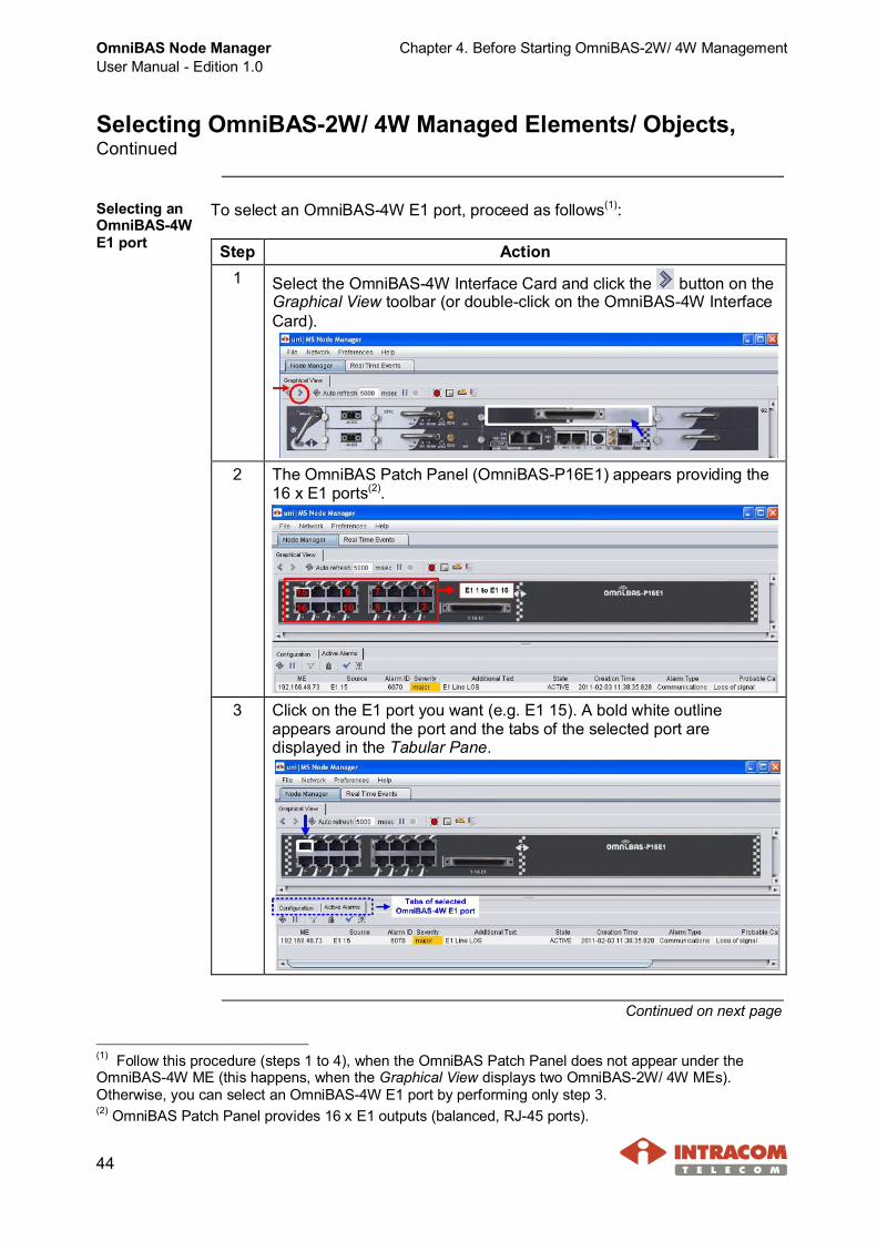
Selecting anOmniBAS-4WE1 port
To select an OmniBAS-4W E1 port, proceed as follows(1):
Step Action1 Select the OmniBAS-4W Interface Card and click the button on the
Graphical View toolbar (or double-click on the OmniBAS-4W InterfaceCard).
2 The OmniBAS Patch Panel (OmniBAS-P16E1) appears providing the16 x Ε1 ports(2).
3 Click on the E1 port you want (e.g. E1 15). A bold white outlineappears around the port and the tabs of the selected port aredisplayed in the Tabular Pane.
Continued on next page
(1) Follow this procedure (steps 1 to 4), when the OmniBAS Patch Panel does not appear under theOmniBAS-4W ME (this happens, when the Graphical View displays two OmniBAS-2W/ 4W MEs).Otherwise, you can select an OmniBAS-4W E1 port by performing only step 3.(2) OmniBAS Patch Panel provides 16 x Ε1 outputs (balanced, RJ-45 ports).

Chapter 4. Before Starting OmniBAS-2W/ 4W Management OmniBAS Node ManagerUser Manual - Edition 1.0
45
Selecting OmniBAS-2W/ 4W Managed Elements/ Objects,Continued
Selecting anOmniBAS-4WE1 port(continued)
Step Action4 To return back to the OmniBAS-4W ME, click the button on the
Graphical View toolbar.
End of procedure.
Opening theActions Menuof anOmniBAS-2WME/ MO
In case you want to use the Actions Menu of an OmniBAS-2W/ 4W ME, cardor port, right-click on it. A bold white outline appears around the selected MEor MO and the Actions Menu related to the selected ME or MO opens.Note that the tabs related to the management actions of the selected ME orMO are also displayed in the Tabular Pane.· Example - Opening the Actions Menu of an OmniBAS-2W/ 4W ME:
To open the Actions Menu corresponding to an OmniBAS-2W/ 4W ME,right-click on its IP address. A bold white outline appears around the selectedME and its Actions Menu opens.
Follow a same procedure to open the Actions Menu of an OmniBAS-2W/ 4Wcard or port.
OmniBAS Node ManagerUser Manual - Edition 1.0
Chapter 4. Before Starting OmniBAS-2W/ 4W Management
46
General Guidelines for Performing Management Actions
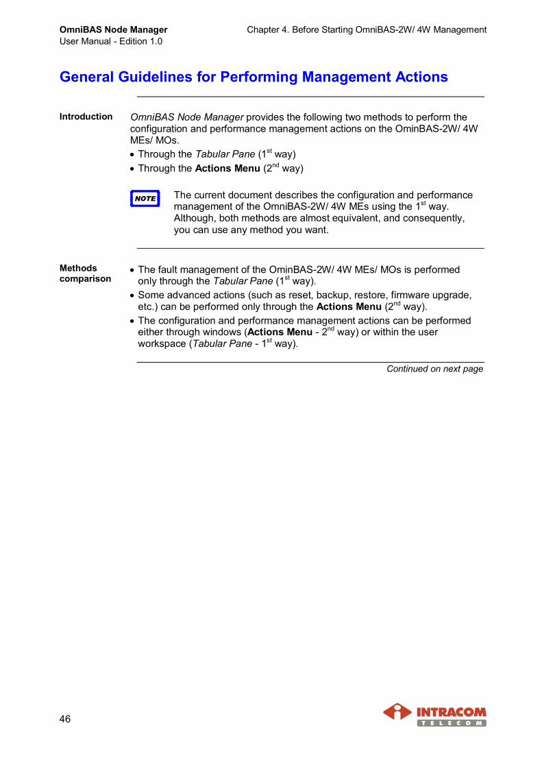
Introduction OmniBAS Node Manager provides the following two methods to perform theconfiguration and performance management actions on the OminBAS-2W/ 4WMEs/ MOs.· Through the Tabular Pane (1st way)· Through the Actions Menu (2nd way)
NOTE The current document describes the configuration and performancemanagement of the OmniBAS-2W/ 4W MEs using the 1st way.Although, both methods are almost equivalent, and consequently,you can use any method you want.
Methodscomparison
· The fault management of the OminBAS-2W/ 4W MEs/ MOs is performedonly through the Tabular Pane (1st way).
· Some advanced actions (such as reset, backup, restore, firmware upgrade,etc.) can be performed only through the Actions Menu (2nd way).
· The configuration and performance management actions can be performedeither through windows (Actions Menu - 2nd way) or within the userworkspace (Tabular Pane - 1st way).
Continued on next page

Chapter 4. Before Starting OmniBAS-2W/ 4W Management OmniBAS Node ManagerUser Manual - Edition 1.0
47
General Guidelines for Performing Management Actions,Continued
Procedure A general procedure to perform a configuration or performance action isprovided below. Execute the following steps using either the 1st or the 2nd way.
Step Action1 · 1st way - Tabular: In the Graphical View, select the OminBAS-2W/ 4W
ME/ MO you want (e.g. OmniBAS-2W Control Card). A bold whiteoutline appears around the selected object. Also, the tabs of theselected ME/ MO appears in the Tabular Pane providing all theconfiguration and performance actions that can be performed on thisME/ MO.
· 2nd way - Actions Menu: In the Graphical View, right-click on theOminBAS-2W/ 4W ME/ MO you want (e.g. OmniBAS-2W ControlCard). A bold white outline appears around the selected ME/ MO.Also, the Actions Menu of the selected ME/ MO appears includingthe available configuration and performance actions that can beperformed on this ME/ MO.
►Generally, the Actions Menu and the Tabular Pane includes similarconfiguration and performance options (see above schematic).
Continued on next page

OmniBAS Node ManagerUser Manual - Edition 1.0
Chapter 4. Before Starting OmniBAS-2W/ 4W Management
48
General Guidelines for Performing Management Actions,Continued
Procedure (continued)
Step Action2 · 1st way - Tabular: Click the tab you want (e.g. Configuration).
· 2nd way - Actions Menu: From the Actions Menu select the actionyou want (e.g. Configuration Data).
Continued on next page
Chapter 4. Before Starting OmniBAS-2W/ 4W Management OmniBAS Node ManagerUser Manual - Edition 1.0
49
General Guidelines for Performing Management Actions,Continued
Procedure (continued)
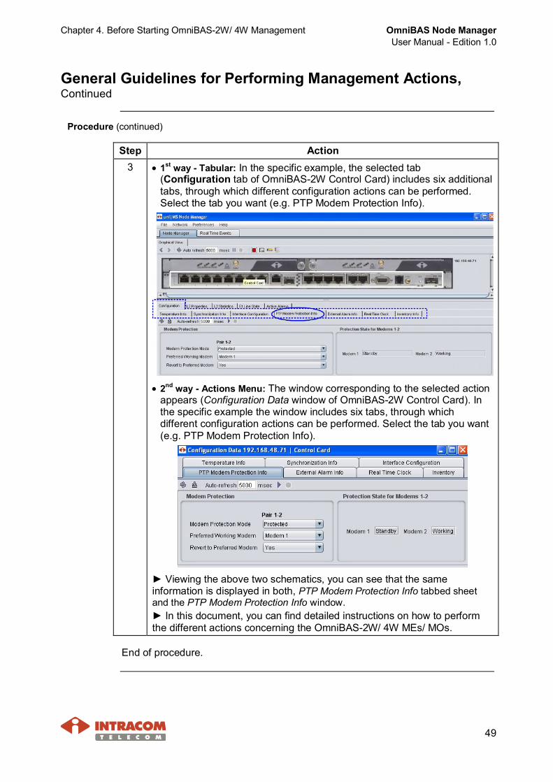
Step Action3 · 1st way - Tabular: In the specific example, the selected tab
(Configuration tab of OmniBAS-2W Control Card) includes six additionaltabs, through which different configuration actions can be performed.Select the tab you want (e.g. PTP Modem Protection Info).
· 2nd way - Actions Menu: The window corresponding to the selected actionappears (Configuration Data window of OmniBAS-2W Control Card). Inthe specific example the window includes six tabs, through whichdifferent configuration actions can be performed. Select the tab you want(e.g. PTP Modem Protection Info).
► Viewing the above two schematics, you can see that the sameinformation is displayed in both, PTP Modem Protection Info tabbed sheetand the PTP Modem Protection Info window.► In this document, you can find detailed instructions on how to performthe different actions concerning the OmniBAS-2W/ 4W MEs/ MOs.
End of procedure.

OmniBAS Node ManagerUser Manual - Edition 1.0
Chapter 4. Before Starting OmniBAS-2W/ 4W Management
50
Configuration Tabbed Sheets
Introduction Through the configuration tabbed sheets provided by the OmniBAS NodeManager, you can change and also monitor the attributes of the connectedOmniBAS-2W/ 4W MEs.There are two types of configuration tabbed sheets, the common tabbedsheets and the list tabbed sheets. The difference is that in a list tabbed sheet,the configuration attributes are displayed in a list form.This paragraph provides the necessary information for using the configurationtabbed sheets.
Editable/non-editablefields
The schematics below show the editable and non-editable fields in a commontabbed sheet and in a list tabbed sheet:
In a Common Tabbed Sheet:· To make changes in the attributes of a common tabbed sheet, use the
corresponding text boxes (boxes in white) and drop-down lists.· The grey-shaded fields are not editable (i.e. they are used only for
monitoring purposes).In a List Tabbed Sheet:
· To change an attribute of a list tabbed sheet, select the row correspondingto this attribute. The selected row becomes green-colored and the editablefields turn into orange. Double-click on the attribute’s field and select thenew value from the drop-down menu that appears (or type the new value inthe text box that appears).
· When you select a row, the non-editable fields turn into white.· When you add a new row, the editable fields are displayed yellow shaded
and the non-editable fields, green shaded.
Continued on next page
Chapter 4. Before Starting OmniBAS-2W/ 4W Management OmniBAS Node ManagerUser Manual - Edition 1.0
51
Configuration Tabbed Sheets, Continued
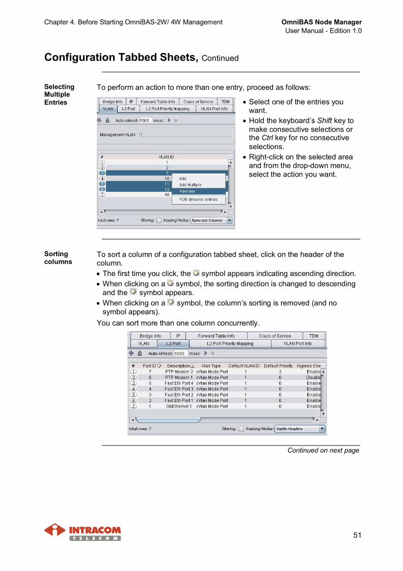
To perform an action to more than one entry, proceed as follows:SelectingMultipleEntries · Select one of the entries you
want.· Hold the keyboard’s Shift key to
make consecutive selections orthe Ctrl key for no consecutiveselections.
· Right-click on the selected areaand from the drop-down menu,select the action you want.
Sortingcolumns
To sort a column of a configuration tabbed sheet, click on the header of thecolumn.· The first time you click, the symbol appears indicating ascending direction.· When clicking on a symbol, the sorting direction is changed to descending
and the symbol appears.· When clicking on a symbol, the column’s sorting is removed (and no
symbol appears).You can sort more than one column concurrently.
Continued on next page
OmniBAS Node ManagerUser Manual - Edition 1.0
Chapter 4. Before Starting OmniBAS-2W/ 4W Management
52
Configuration Tabbed Sheets, Continued
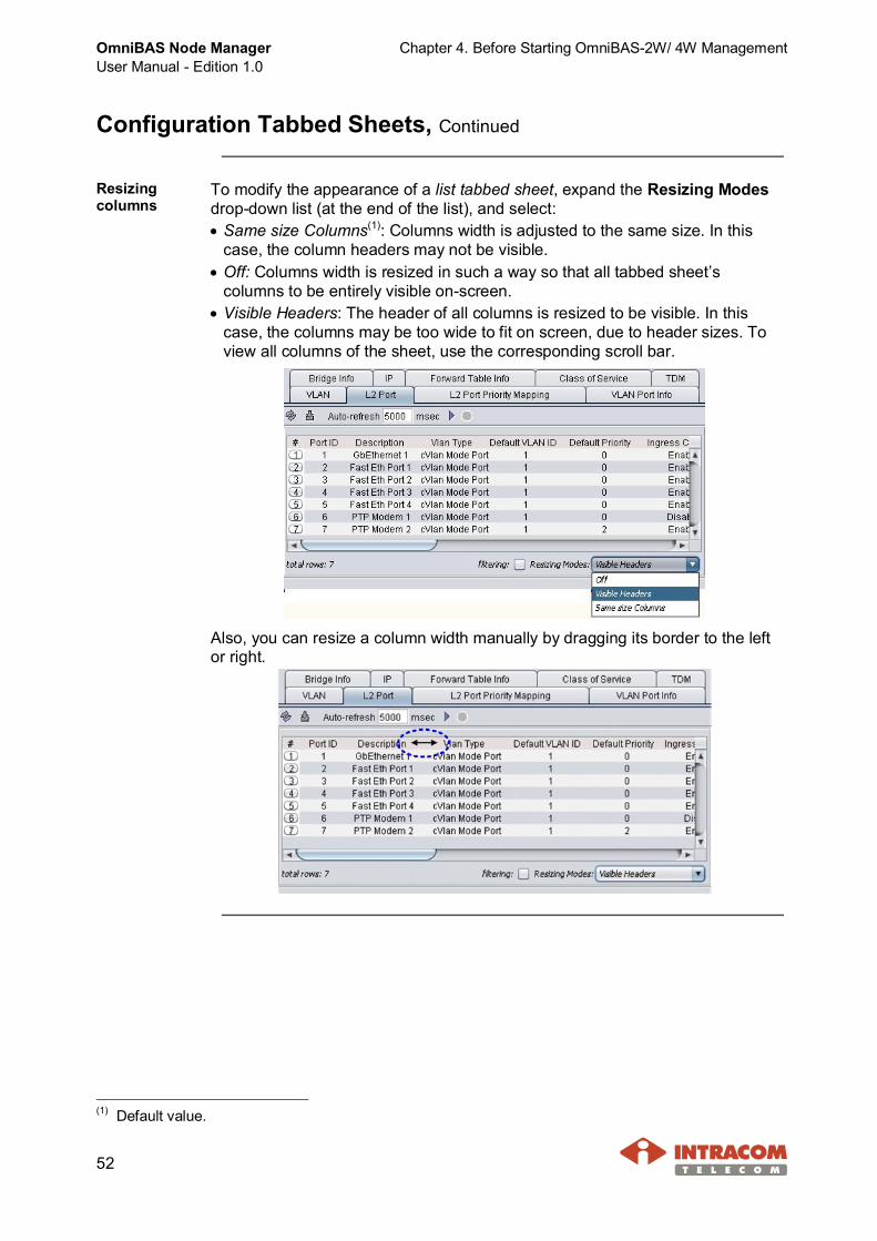
Resizingcolumns
To modify the appearance of a list tabbed sheet, expand the Resizing Modesdrop-down list (at the end of the list), and select:· Same size Columns(1): Columns width is adjusted to the same size. In this
case, the column headers may not be visible.· Off: Columns width is resized in such a way so that all tabbed sheet’s
columns to be entirely visible on-screen.· Visible Headers: The header of all columns is resized to be visible. In this
case, the columns may be too wide to fit on screen, due to header sizes. Toview all columns of the sheet, use the corresponding scroll bar.
Also, you can resize a column width manually by dragging its border to the leftor right.
(1) Default value.

Chapter 4. Before Starting OmniBAS-2W/ 4W Management OmniBAS Node ManagerUser Manual - Edition 1.0
53
Active Alarms & Real Time Events Lists
Introduction This paragraph describes how to perform multiple entries selection in anActive Alarms or Real Time Events list and also how to sort, move or resizethe columns of the list.
To perform an allowed action(1) to more than one alarm/ event, proceed asfollows:
· In the Active Alarmsor Real Time Eventslist, select one of thealarms/ events youwant.
· Hold the keyboard’sShift key to makeconsecutive selectionsor the Ctrl key for noconsecutiveselections.
Selectingmultiplealarms/ events
· Right-click on the selected area and from the drop-down menu, select theaction you want.
To sort an Active Alarms or Real Time Events list by a column, click on theheader of the column (e.g. Alarm ID).
· The first time you click, thesymbol appears indicatingascending direction.
· When clicking on a symbol, thesorting direction is changed todescending and the symbolappears.
· When clicking on a symbol,the column’s sorting is removed(and no symbol appears).
Using SortingRules
Note that you can sort an Active Alarms or Real Time Events list only by onecolumn (alarm property).
Continued on next page
(1) Note that only some actions can be performed massively. For instance, you can acknowledge or clearmultiple alarms but you cannot perform a Configuration Data action to multiple Fast Ethernet ports. So,if you select more than one Fast Ethernet ports and then, select the Configuration Data action from thedrop-down menu, only the Configuration Data window of the last selected Fast Ethernet port will bedisplayed.
OmniBAS Node ManagerUser Manual - Edition 1.0
Chapter 4. Before Starting OmniBAS-2W/ 4W Management
54
Active Alarms & Real Time Events Lists, Continued
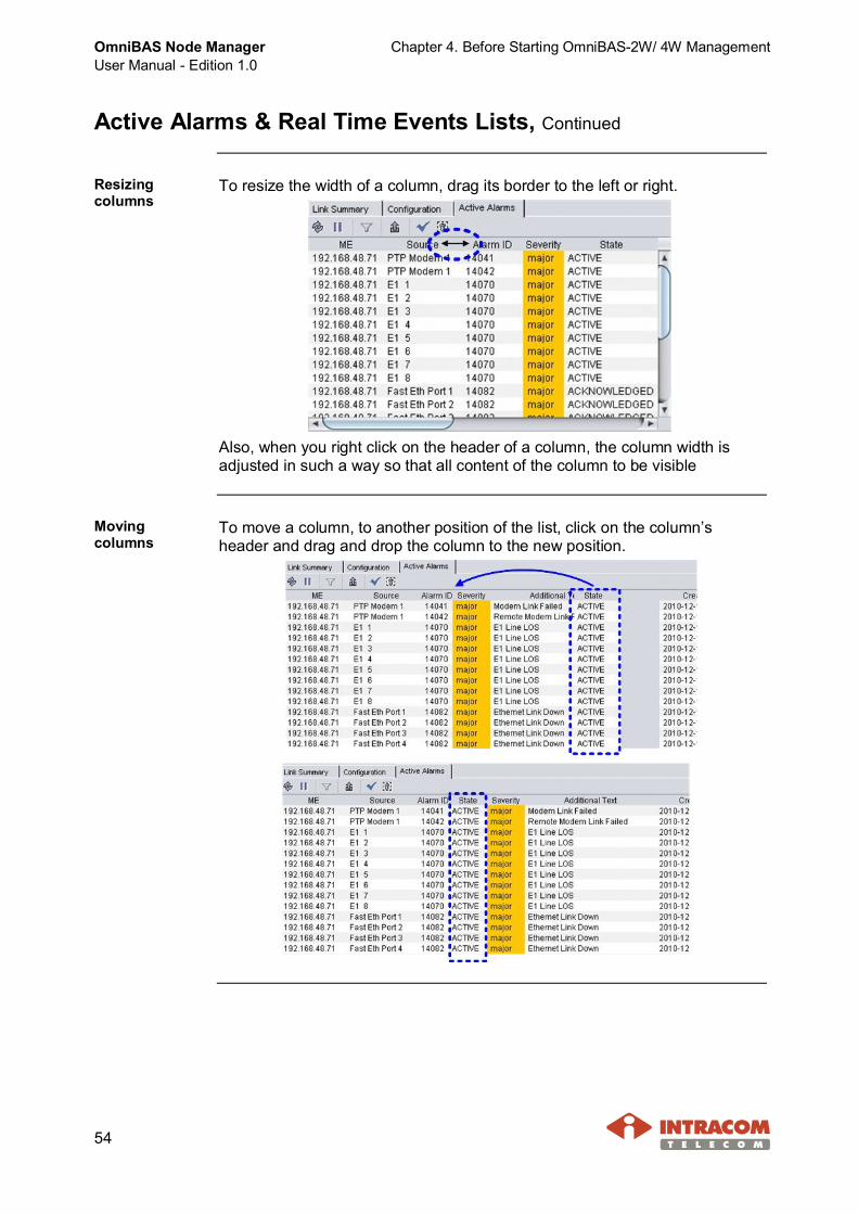
Resizingcolumns
To resize the width of a column, drag its border to the left or right.
Also, when you right click on the header of a column, the column width isadjusted in such a way so that all content of the column to be visible
Movingcolumns
To move a column, to another position of the list, click on the column’sheader and drag and drop the column to the new position.
Chapter 4. Before Starting OmniBAS-2W/ 4W Management OmniBAS Node ManagerUser Manual - Edition 1.0
55
Filtering a List (Active Alarms or Real Time Events)
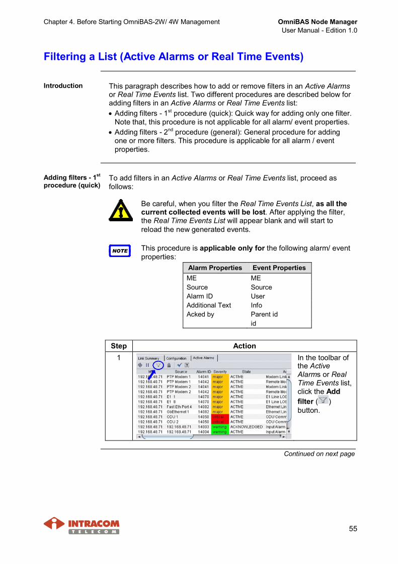
Introduction This paragraph describes how to add or remove filters in an Active Alarmsor Real Time Events list. Two different procedures are described below foradding filters in an Active Alarms or Real Time Events list:· Adding filters - 1st procedure (quick): Quick way for adding only one filter.
Note that, this procedure is not applicable for all alarm/ event properties.· Adding filters - 2nd procedure (general): General procedure for adding
one or more filters. This procedure is applicable for all alarm / eventproperties.
Adding filters - 1st
procedure (quick)To add filters in an Active Alarms or Real Time Events list, proceed asfollows:
Be careful, when you filter the Real Time Events List, as all thecurrent collected events will be lost. After applying the filter,the Real Time Events List will appear blank and will start toreload the new generated events.
NOTE This procedure is applicable only for the following alarm/ eventproperties:
Alarm Properties Event PropertiesME MESource SourceAlarm ID UserAdditional Text InfoAcked by Parent id
id
Step Action1 In the toolbar of
the ActiveAlarms or RealTime Events list,click the Addfilter ( )button.
Continued on next page

OmniBAS Node ManagerUser Manual - Edition 1.0
Chapter 4. Before Starting OmniBAS-2W/ 4W Management
56
Filtering a List (Active Alarms or Real Time Events), Continued
Adding filters - 1st procedure (quick) (continued)
Step Action2 In the filter bar that
appears,double-click in thefield correspondingto the alarm propertyyou want (e.g. AlarmID).
3 Type the filter value(e.g. 14041) andpress Enter.
4 In case you filter the Real Time Events list, the followingconfirmation message appears, warning you that all the currentcollected events will be lost. To proceed click Yes; otherwise clickNo.
Continued on next page
Chapter 4. Before Starting OmniBAS-2W/ 4W Management OmniBAS Node ManagerUser Manual - Edition 1.0
57
Filtering a List (Active Alarms or Real Time Events), Continued
Adding filters - 1st procedure (quick) (continued)
Step Action5 · In case you filter an
Active Alarms list, thefiltered alarms appear inthe Active Alarms list.
· In case you filter theReal Time Events list,the list appears blank(as the previouscollected events havebeen cleared). The RealTime Events list willstart to reload the newgenerated events.
The symbol next to a property-column (in the Active Alarms or RealTime Events list) denotes the existence of a filter in this column.
End of procedure.
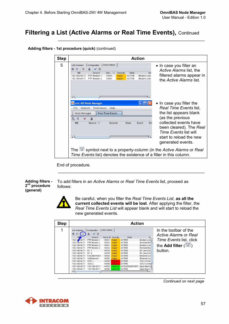
Adding filters -2nd procedure(general)
To add filters in an Active Alarms or Real Time Events list, proceed asfollows:
Be careful, when you filter the Real Time Events List, as all thecurrent collected events will be lost. After applying the filter, theReal Time Events List will appear blank and will start to reload thenew generated events.
Step Action1 In the toolbar of the
Active Alarms or RealTime Events list, clickthe Add filter ( )button.
Continued on next page

OmniBAS Node ManagerUser Manual - Edition 1.0
Chapter 4. Before Starting OmniBAS-2W/ 4W Management
58
Filtering a List (Active Alarms or Real Time Events), Continued
Adding filters - 2nd procedure (general) (continued)
Step Action2 In the filter bar that
appears, click in the fieldcorresponding to thealarm property you want(e.g. Alarm ID).If a button appears onthe right of the selectedfield, click on it.
3 In the Apply ColumnFilter window thatappears double-click:· In the Value field to
type (or select) thevalue.
· In the Conditiondrop-down list to selectthe condition.
4 In case you want to addmore filters, click theAdd New Filter button.Set the value and thecondition for the newfilter.
Also, select from the Operator drop-down list, the Logical AND orLogical OR function.
5 In case you filter the Real Time Events list, the following confirmationmessage appears, warning you that all the current collected eventswill be lost. To proceed click Yes; otherwise click No.
Continued on next page
Chapter 4. Before Starting OmniBAS-2W/ 4W Management OmniBAS Node ManagerUser Manual - Edition 1.0
59
Filtering a List (Active Alarms or Real Time Events), Continued
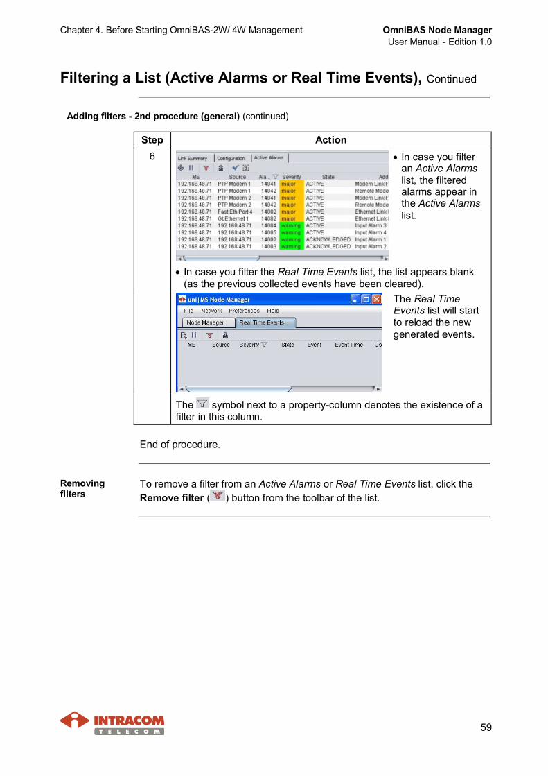
Adding filters - 2nd procedure (general) (continued)
Step Action6 · In case you filter
an Active Alarmslist, the filteredalarms appear inthe Active Alarmslist.
· In case you filter the Real Time Events list, the list appears blank(as the previous collected events have been cleared).
The Real TimeEvents list will startto reload the newgenerated events.
The symbol next to a property-column denotes the existence of afilter in this column.
End of procedure.
Removingfilters
To remove a filter from an Active Alarms or Real Time Events list, click theRemove filter ( ) button from the toolbar of the list.

OmniBAS Node ManagerUser Manual - Edition 1.0
Chapter 4. Before Starting OmniBAS-2W/ 4W Management
60
Exporting an Active Alarms or Real Time Events List
Introduction This paragraph describes how to export the alarms or events informationincluded in an Active Alarms or Real Time Events list.
Procedure To export the alarms information included in an Active Alarms or Real TimeEvents list, proceed as follows:
Step Action1 In the toolbar of the
Active Alarms orReal Time Eventslist, click the Export( ) button.
2 In the Save window thatappears, enter the file’sname and select the typeof the file (select csv).Click Save.
3 In the following message that appears, click OK.
4 The csv file including the alarms or events information is saved.
Continued on next page
Chapter 4. Before Starting OmniBAS-2W/ 4W Management OmniBAS Node ManagerUser Manual - Edition 1.0
61
Exporting an Active Alarms or Real Time Events List, Continued
Procedure (continued)
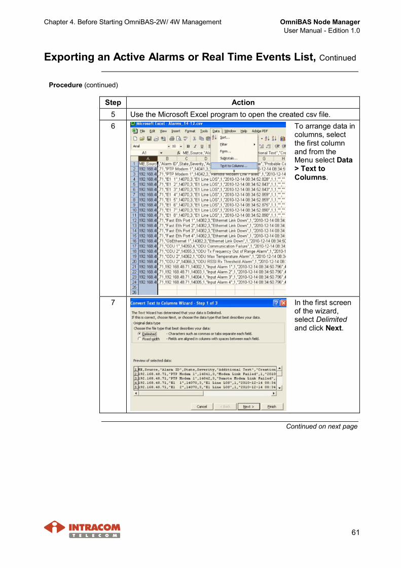
Step Action5 Use the Microsoft Excel program to open the created csv file.6 To arrange data in
columns, selectthe first columnand from theMenu select Data> Text toColumns.
7 In the first screenof the wizard,select Delimitedand click Next.
Continued on next page

OmniBAS Node ManagerUser Manual - Edition 1.0
Chapter 4. Before Starting OmniBAS-2W/ 4W Management
62
Exporting an Active Alarms or Real Time Events List, Continued
Procedure (continued)
Step Action8 In the second
screen of thewizard, selectthe delimitercurrently usedby OmniBASNode Managerand click Next.By default,OmniBAS NodeManager usesthe Commasymbol as exportfield delimiter.
NOTETo identify the export field delimiter currently used, selectPreferences > Set Preferences and click theMiscellaneous option (see also, par. GUI Customization,on page 35).
Continued on next page
Chapter 4. Before Starting OmniBAS-2W/ 4W Management OmniBAS Node ManagerUser Manual - Edition 1.0
63
Exporting an Active Alarms or Real Time Events List, Continued
Procedure (continued)
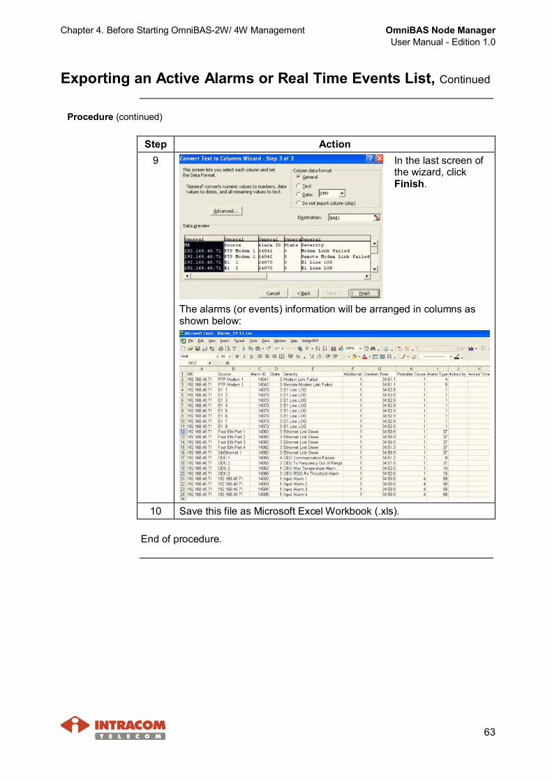
Step Action9 In the last screen of
the wizard, clickFinish.
The alarms (or events) information will be arranged in columns asshown below:
10 Save this file as Microsoft Excel Workbook (.xls).
End of procedure.

OmniBAS Node ManagerUser Manual - Edition 1.0
Chapter 5. Configuring an OmniBAS-2W/ 4W ME
64
5 Configuring an OmniBAS-2W/ 4W ME
This chapter includes the following topics through which all proceduresneeded for configuring an OmniBAS-2W/ 4W ME are provided:· Quick (& First) Configuration of OmniBAS-2W/ 4W ME· Configuring Control Card· Configuring Modem Parameters· Configuring ODU Parameters
Chapter 5. Configuring an OmniBAS-2W/ 4W ME OmniBAS Node ManagerUser Manual - Edition 1.0
65
5.1 Quick (& First) Configuration of OmniBAS-2W/ 4W ME
Introduction This section describes how to:· Configure an OmniBAS-2W/ 4W ME for the fist time.· Configure the connected Modem Cards and ODU of the selected
OmniBAS-2W/ 4W ME.· Set the inband management parameters of the selected OmniBAS-2W/
4W ME.
Opening theStartup Config.window
To open the Startup Configuration window of an OmniBAS-2W/ 4W ME/MO, proceed as follows:
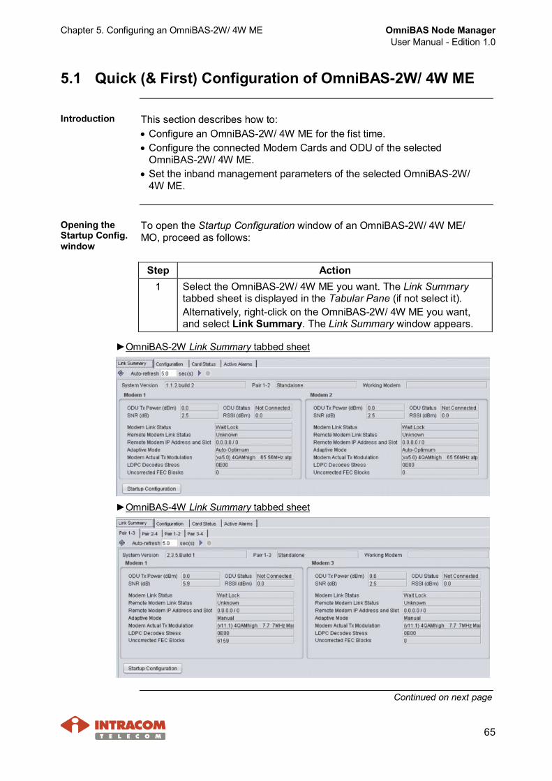
Step Action1 Select the OmniBAS-2W/ 4W ME you want. The Link Summary
tabbed sheet is displayed in the Tabular Pane (if not select it).Alternatively, right-click on the OmniBAS-2W/ 4W ME you want,and select Link Summary. The Link Summary window appears.
►OmniBAS-2W Link Summary tabbed sheet
►OmniBAS-4W Link Summary tabbed sheet
Continued on next page
OmniBAS Node ManagerUser Manual - Edition 1.0
Chapter 5. Configuring an OmniBAS-2W/ 4W ME
66
Quick (& First) Configuration of OmniBAS-2W/ 4W ME, Continued
Opening the Startup Config. window (continued)
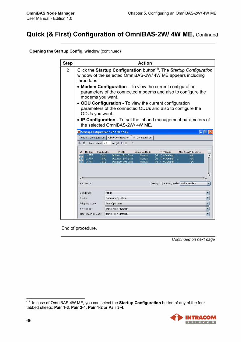
Step Action2 Click the Startup Configuration button(1). The Startup Configuration
window of the selected OmniBAS-2W/ 4W ME appears includingthree tabs:· Modem Configuration - To view the current configuration
parameters of the connected modems and also to configure themodems you want.
· ODU Configuration - To view the current configurationparameters of the connected ODUs and also to configure theODUs you want.
· IP Configuration - To set the inband management parameters ofthe selected OmniBAS-2W/ 4W ME.
End of procedure.
Continued on next page
(1) In case of OmniBAS-4W ME, you can select the Startup Configuration button of any of the fourtabbed sheets: Pair 1-3, Pair 2-4, Pair 1-2 or Pair 3-4.

Chapter 5. Configuring an OmniBAS-2W/ 4W ME OmniBAS Node ManagerUser Manual - Edition 1.0
67
Quick (& First) Configuration of OmniBAS-2W/ 4W ME, Continued
Modem Cardsconfiguration
To configure the Modem Cards of an OmniBAS-2W/ 4W ME, proceed asfollows:
NOTE To configure an OmniBAS-2W/ 4W radio link, perform theprocedure provided in this paragraph to both modems of the link(local and remote).
When you change the configuration of an OmniBAS-2W/ 4Wmodem, link downtime is caused. For this reason:· Select a convenient time for changing the configuration of
the modem.· Start with the configuration of the remote modem.
Otherwise, communication loss with the remote modem willtake place and a visit to the site will be required.
The configuration of an OmniBAS-2W/ 4W modem must bemade only by qualified personnel and according the RFplanning.
Step Action1 In the Startup Configuration window, click the Modem Configuration
tab. The Modem Configuration tabbed sheet appears displaying (atthe upper part) the current configuration parameters of the connectedModem Cards for the selected OmniBAS-2W/ 4W ME.
Continued on next page
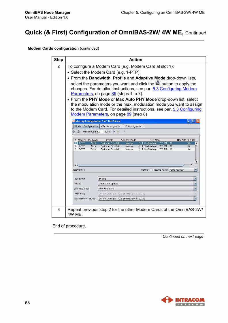
OmniBAS Node ManagerUser Manual - Edition 1.0
Chapter 5. Configuring an OmniBAS-2W/ 4W ME
68
Quick (& First) Configuration of OmniBAS-2W/ 4W ME, Continued
Modem Cards configuration (continued)
Step Action2 To configure a Modem Card (e.g. Modem Card at slot 1):
· Select the Modem Card (e.g. 1-PTP).· From the Bandwidth, Profile and Adaptive Mode drop-down lists,
select the parameters you want and click the button to apply thechanges. For detailed instructions, see par. 5.3 Configuring ModemParameters, on page 89 (steps 1 to 7).
· From the PHY Mode or Max Auto PHY Mode drop-down list, selectthe modulation mode or the max. modulation mode you want to assignto the Modem Card. For detailed instructions, see par. 5.3 ConfiguringModem Parameters, on page 89 (step 8)
3 Repeat previous step 2 for the other Modem Cards of the OmniBAS-2W/4W ME.
End of procedure.
Continued on next page
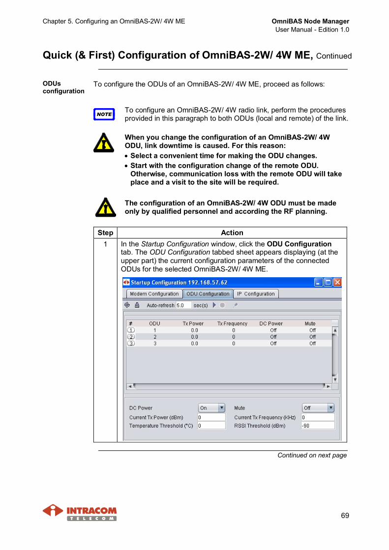
Chapter 5. Configuring an OmniBAS-2W/ 4W ME OmniBAS Node ManagerUser Manual - Edition 1.0
69
Quick (& First) Configuration of OmniBAS-2W/ 4W ME, Continued
ODUsconfiguration
To configure the ODUs of an OmniBAS-2W/ 4W ME, proceed as follows:
NOTETo configure an OmniBAS-2W/ 4W radio link, perform the proceduresprovided in this paragraph to both ODUs (local and remote) of the link.
When you change the configuration of an OmniBAS-2W/ 4WODU, link downtime is caused. For this reason:· Select a convenient time for making the ODU changes.· Start with the configuration change of the remote ODU.
Otherwise, communication loss with the remote ODU will takeplace and a visit to the site will be required.
The configuration of an OmniBAS-2W/ 4W ODU must be madeonly by qualified personnel and according the RF planning.
Step Action1 In the Startup Configuration window, click the ODU Configuration
tab. The ODU Configuration tabbed sheet appears displaying (at theupper part) the current configuration parameters of the connectedODUs for the selected OmniBAS-2W/ 4W ME.
Continued on next page
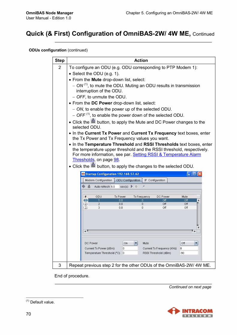
OmniBAS Node ManagerUser Manual - Edition 1.0
Chapter 5. Configuring an OmniBAS-2W/ 4W ME
70
Quick (& First) Configuration of OmniBAS-2W/ 4W ME, Continued
ODUs configuration (continued)
Step Action2 To configure an ODU (e.g. ODU corresponding to PTP Modem 1):
· Select the ODU (e.g. 1).· From the Mute drop-down list, select:- ON (1), to mute the ODU. Muting an ODU results in transmission
interruption of the ODU.- OFF, to unmute the ODU.
· From the DC Power drop-down list, select:- ON, to enable the power up of the selected ODU.- OFF (1), to enable the power down of the selected ODU.
· Click the button, to apply the Mute and DC Power changes to theselected ODU.
· In the Current Tx Power and Current Tx Frequency text boxes, enterthe Tx Power and Tx Frequency values you want.
· In the Temperature Threshold and RSSI Thresholds text boxes, enterthe temperature upper threshold and the RSSI threshold, respectively.For more information, see par. Setting RSSI & Temperature AlarmThresholds, on page 98.
· Click the button, to apply the changes to the selected ODU.
3 Repeat previous step 2 for the other ODUs of the OmniBAS-2W/ 4W ME.
End of procedure.
Continued on next page
(1) Default value.
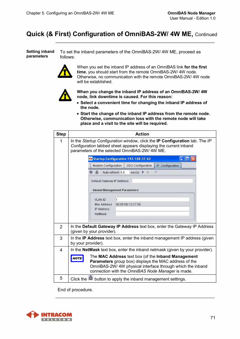
Chapter 5. Configuring an OmniBAS-2W/ 4W ME OmniBAS Node ManagerUser Manual - Edition 1.0
71
Quick (& First) Configuration of OmniBAS-2W/ 4W ME, Continued
Setting inbandparameters
To set the inband parameters of the OmniBAS-2W/ 4W ME, proceed asfollows:
When you set the inband IP address of an OmniBAS link for the firsttime, you should start from the remote OmniBAS-2W/ 4W node.Otherwise, no communication with the remote OmniBAS-2W/ 4W nodewill be established.
When you change the inband IP address of an OmniBAS-2W/ 4Wnode, link downtime is caused. For this reason:· Select a convenient time for changing the inband IP address of
the node.· Start the change of the inband IP address from the remote node.
Otherwise, communication loss with the remote node will takeplace and a visit to the site will be required.
Step Action1 In the Startup Configuration window, click the IP Configuration tab. The IP
Configuration tabbed sheet appears displaying the current inbandparameters of the selected OmniBAS-2W/ 4W ME.
2 In the Default Gateway IP Address text box, enter the Gateway IP Address(given by your provider).
3 In the IP Address text box, enter the inband management IP address (givenby your provider).
4 In the NetMask text box, enter the inband netmask (given by your provider).
NOTE The MAC Address text box (of the Inband ManagementParameters group box) displays the MAC address of theOmniBAS-2W/ 4W physical interface through which the inbandconnection with the OmniBAS Node Manager is made.
5 Click the button to apply the inband management settings.
End of procedure.

OmniBAS Node ManagerUser Manual - Edition 1.0
Chapter 5. Configuring an OmniBAS-2W/ 4W ME
72
5.2 Configuring Control Card
This section provides the following procedures for carrying out essentialconfiguration settings in an OmniBAS-2W/ 4W ME through the Control Card:· Setting Real Time Clock· Configuring OmniBAS-2W/ 4W System Synchronization· Configuring Modems' Operational Mode· Configuring GbE/ FE Ports· Configuring the E1 Ports
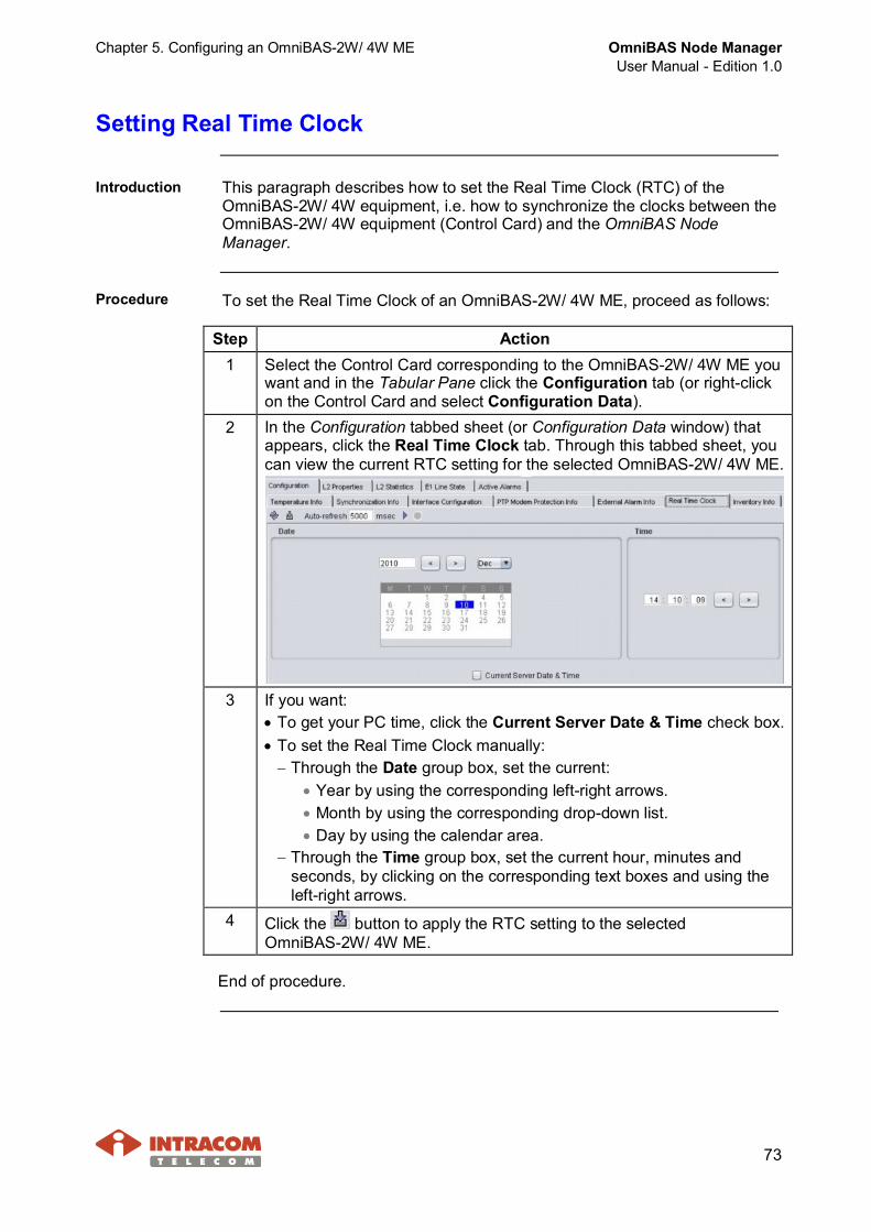
Chapter 5. Configuring an OmniBAS-2W/ 4W ME OmniBAS Node ManagerUser Manual - Edition 1.0
73
Setting Real Time Clock
Introduction This paragraph describes how to set the Real Time Clock (RTC) of theOmniBAS-2W/ 4W equipment, i.e. how to synchronize the clocks between theOmniBAS-2W/ 4W equipment (Control Card) and the OmniBAS NodeManager.
Procedure To set the Real Time Clock of an OmniBAS-2W/ 4W ME, proceed as follows:
Step Action1 Select the Control Card corresponding to the OmniBAS-2W/ 4W ME you
want and in the Tabular Pane click the Configuration tab (or right-clickon the Control Card and select Configuration Data).
2 In the Configuration tabbed sheet (or Configuration Data window) thatappears, click the Real Time Clock tab. Through this tabbed sheet, youcan view the current RTC setting for the selected OmniBAS-2W/ 4W ME.
3 If you want:· To get your PC time, click the Current Server Date & Time check box.· To set the Real Time Clock manually:- Through the Date group box, set the current:
· Year by using the corresponding left-right arrows.· Month by using the corresponding drop-down list.· Day by using the calendar area.
- Through the Time group box, set the current hour, minutes andseconds, by clicking on the corresponding text boxes and using theleft-right arrows.
4 Click the button to apply the RTC setting to the selectedOmniBAS-2W/ 4W ME.
End of procedure.
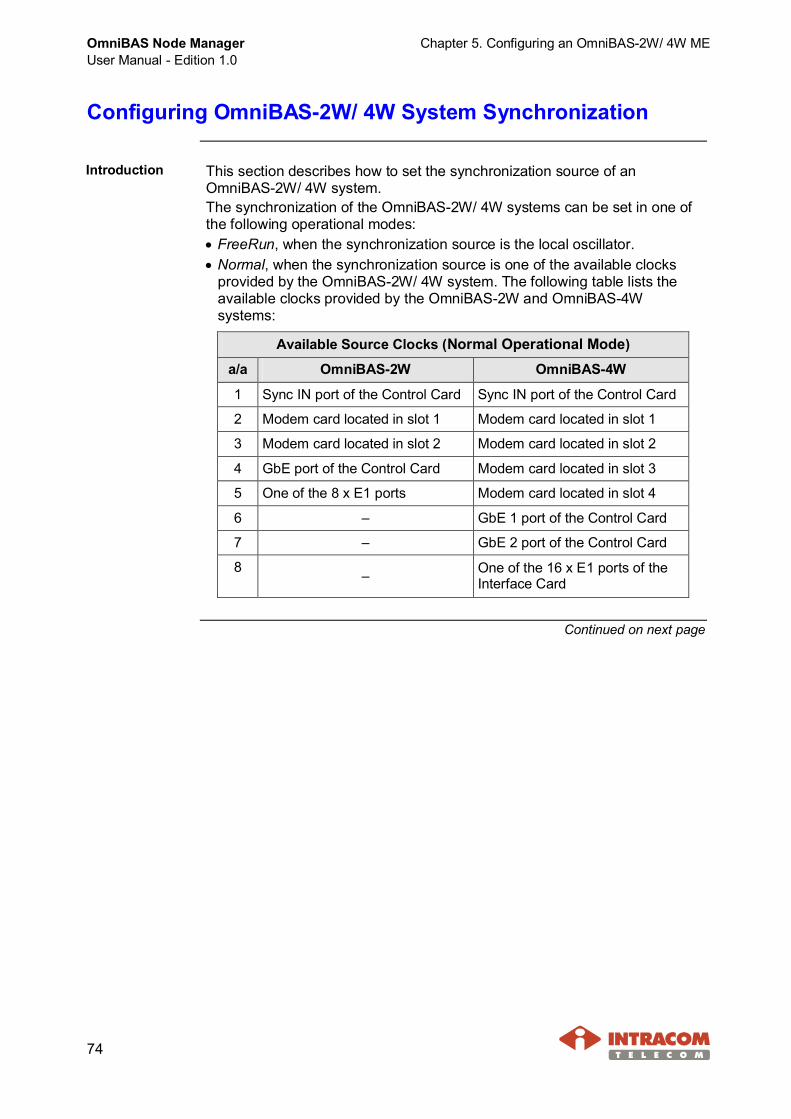
OmniBAS Node ManagerUser Manual - Edition 1.0
Chapter 5. Configuring an OmniBAS-2W/ 4W ME
74
Configuring OmniBAS-2W/ 4W System Synchronization
Introduction This section describes how to set the synchronization source of anOmniBAS-2W/ 4W system.The synchronization of the OmniBAS-2W/ 4W systems can be set in one ofthe following operational modes:· FreeRun, when the synchronization source is the local oscillator.· Normal, when the synchronization source is one of the available clocks
provided by the OmniBAS-2W/ 4W system. The following table lists theavailable clocks provided by the OmniBAS-2W and OmniBAS-4Wsystems:
Available Source Clocks (Normal Operational Mode)
a/a OmniBAS-2W OmniBAS-4W
1 Sync IN port of the Control Card Sync IN port of the Control Card
2 Modem card located in slot 1 Modem card located in slot 1
3 Modem card located in slot 2 Modem card located in slot 2
4 GbE port of the Control Card Modem card located in slot 3
5 One of the 8 x E1 ports Modem card located in slot 4
6 – GbE 1 port of the Control Card
7 – GbE 2 port of the Control Card
8 – One of the 16 x E1 ports of theInterface Card
Continued on next page

Chapter 5. Configuring an OmniBAS-2W/ 4W ME OmniBAS Node ManagerUser Manual - Edition 1.0
75
Configuring OmniBAS-2W/ 4W System Synchronization,Continued
Setting Normaloperationalmode
When the OmniBAS-2W/ 4W synchronization is set to Normal operationalmode, the OmniBAS-2W/ 4W system gets synchronization from one of theavailable clock sources. To set the synchronization of an OmniBAS-2W/ 4Wsystem in Normal operational mode, proceed as follows:
Step Action1 Select the Control Card corresponding to the OmniBAS-2W/ 4W ME
you want and in the Tabular Pane click the Configuration tab (orright-click on the Control Card and select Configuration Data).
2 In the Configuration tabbed sheet (or Configuration Data window)that appears, click the Synchronization Info tab.►OmniBAS-2W Synchronization Info tabbed sheet
►OmniBAS-4W Synchronization Info tabbed sheet
3 From the Operational Mode drop-down list, select Normal.
Continued on next page
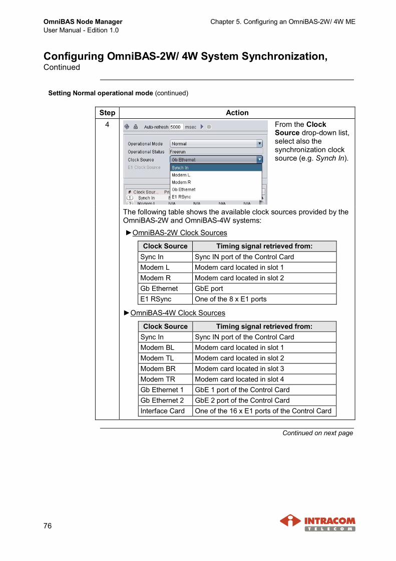
OmniBAS Node ManagerUser Manual - Edition 1.0
Chapter 5. Configuring an OmniBAS-2W/ 4W ME
76
Configuring OmniBAS-2W/ 4W System Synchronization,Continued
Setting Normal operational mode (continued)
Step Action4 From the Clock
Source drop-down list,select also thesynchronization clocksource (e.g. Synch In).
The following table shows the available clock sources provided by theOmniBAS-2W and OmniBAS-4W systems:
►OmniBAS-2W Clock Sources
Clock Source Timing signal retrieved from:Sync In Sync IN port of the Control CardModem L Modem card located in slot 1Modem R Modem card located in slot 2Gb Ethernet GbE portE1 RSync One of the 8 x E1 ports
►OmniBAS-4W Clock Sources
Clock Source Timing signal retrieved from:Sync In Sync IN port of the Control CardModem BL Modem card located in slot 1Modem TL Modem card located in slot 2Modem BR Modem card located in slot 3Modem TR Modem card located in slot 4Gb Ethernet 1 GbE 1 port of the Control CardGb Ethernet 2 GbE 2 port of the Control CardInterface Card One of the 16 x E1 ports of the Control Card
Continued on next page
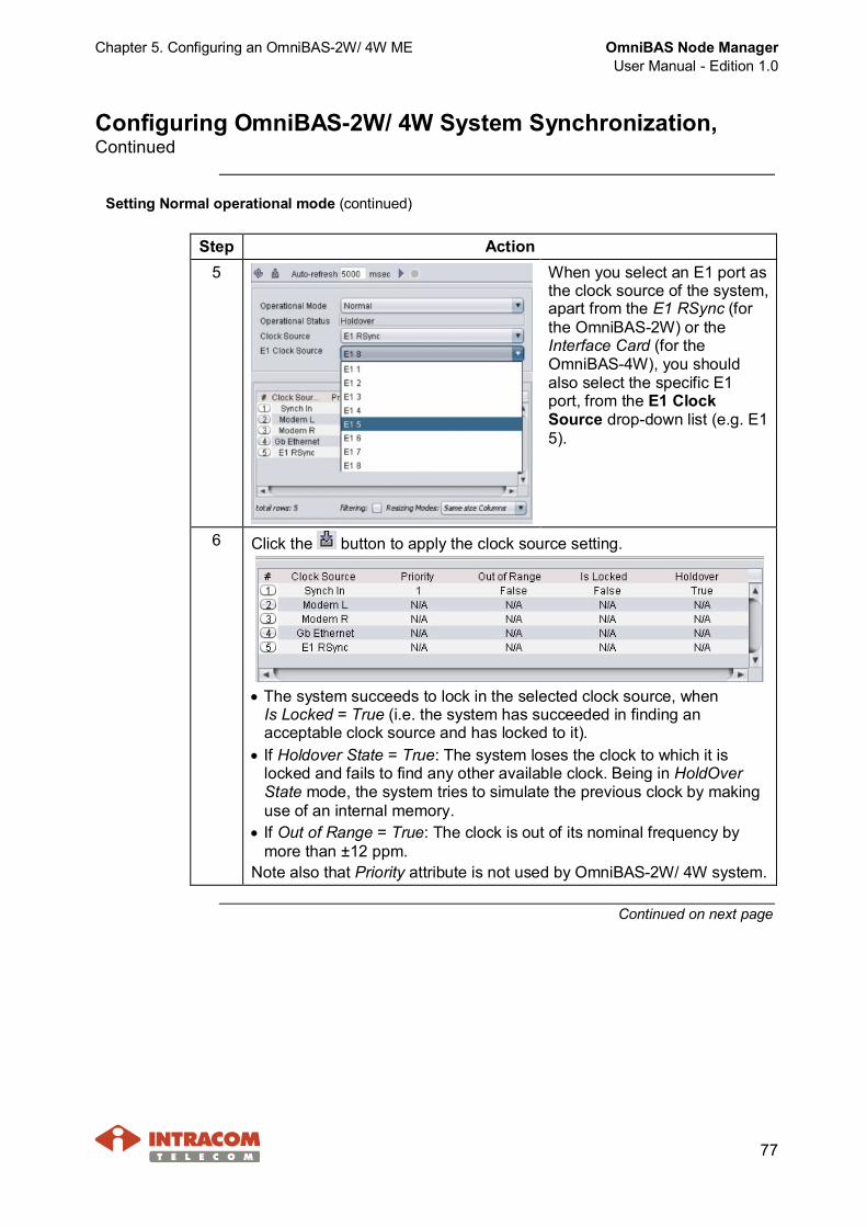
Chapter 5. Configuring an OmniBAS-2W/ 4W ME OmniBAS Node ManagerUser Manual - Edition 1.0
77
Configuring OmniBAS-2W/ 4W System Synchronization,Continued
Setting Normal operational mode (continued)
Step Action5 When you select an E1 port as
the clock source of the system,apart from the E1 RSync (forthe OmniBAS-2W) or theInterface Card (for theOmniBAS-4W), you shouldalso select the specific E1port, from the E1 ClockSource drop-down list (e.g. E15).
6 Click the button to apply the clock source setting.
· The system succeeds to lock in the selected clock source, whenIs Locked = True (i.e. the system has succeeded in finding anacceptable clock source and has locked to it).
· If Holdover State = True: The system loses the clock to which it islocked and fails to find any other available clock. Being in HoldOverState mode, the system tries to simulate the previous clock by makinguse of an internal memory.
· If Out of Range = True: The clock is out of its nominal frequency bymore than ±12 ppm.
Note also that Priority attribute is not used by OmniBAS-2W/ 4W system.
Continued on next page

OmniBAS Node ManagerUser Manual - Edition 1.0
Chapter 5. Configuring an OmniBAS-2W/ 4W ME
78
Configuring OmniBAS-2W/ 4W System Synchronization,Continued
Setting Normal operational mode (continued)
Step Action7 Check also, the current Operation Status for the synchronization of the
OmniBAS-2W/ 4W system that takes one of the following values:· Locked, when the
system hassucceeded infinding anacceptable clocksource and haslocked to it.
· HoldOver, when the system enters HoldOver mode as soon as it losesthe clock to which it is locked and fails to find any other available clock.Being in HoldOver mode, the system tries to simulate the previous clockby making use of an internal memory.
· FreeRun, when the system enters FreeRun mode when there is noavailable clock source and the internal simulation memory of the systemhas not been filled up to allow the system work in HoldOver mode.
Also, a corresponding state icon appears on the Control Card indicatingthe Operation Status for the synchronization of the OmniBAS-2W/ 4Wsystem, as shown in the following table:
Icon Color DescriptionGreen Indicates the Locked operational mode for the
synchronization of the OmniBAS-2W/ 4W ME.Orange Indicates the HoldOver operational mode for the
synchronization of the OmniBAS-2W/ 4W ME.Grey Indicates the Freerun operational mode for the
synchronization of the OmniBAS-2W/ 4W ME.
End of procedure.
Continued on next page
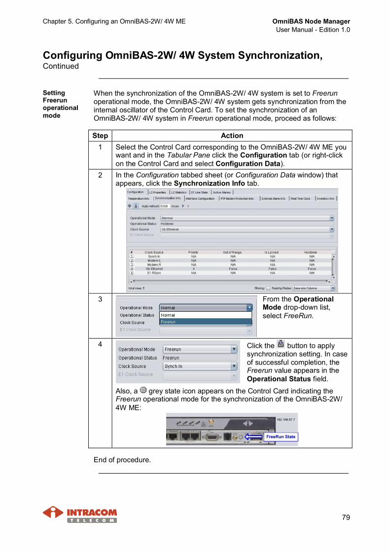
Chapter 5. Configuring an OmniBAS-2W/ 4W ME OmniBAS Node ManagerUser Manual - Edition 1.0
79
Configuring OmniBAS-2W/ 4W System Synchronization,Continued
SettingFreerunoperationalmode
When the synchronization of the OmniBAS-2W/ 4W system is set to Freerunoperational mode, the OmniBAS-2W/ 4W system gets synchronization from theinternal oscillator of the Control Card. To set the synchronization of anOmniBAS-2W/ 4W system in Freerun operational mode, proceed as follows:
Step Action1 Select the Control Card corresponding to the OmniBAS-2W/ 4W ME you
want and in the Tabular Pane click the Configuration tab (or right-clickon the Control Card and select Configuration Data).
2 In the Configuration tabbed sheet (or Configuration Data window) thatappears, click the Synchronization Info tab.
3 From the OperationalMode drop-down list,select FreeRun.
4 Click the button to applysynchronization setting. In caseof successful completion, theFreerun value appears in theOperational Status field.
Also, a grey state icon appears on the Control Card indicating theFreerun operational mode for the synchronization of the OmniBAS-2W/4W ME:
End of procedure.

OmniBAS Node ManagerUser Manual - Edition 1.0
Chapter 5. Configuring an OmniBAS-2W/ 4W ME
80
Configuring Modems' Operational Mode
Introduction This paragraph describes how to configure the modems’ operational mode of anOmniBAS-2W/ 4W ME.· The operational mode of the OmniBAS-2W modems can be configured as:- Standalone for 1+0 or 2+0 configuration- Protected for 1+1 configuration
· The operational mode of the OmniBAS-4W modems(1) can be configured as:- Standalone for 1+0, 2+0, 3+0 or 4+0 configuration- Protected for 1+1 or 2+2 configuration
Procedure To configure the modems’ operational mode in an OmniBAS-2W/ 4W ME,proceed as follows:
Step Action1 Select the Control Card corresponding to the OmniBAS-2W/ 4W ME
you want and in the Tabular Pane click the Configuration tab (orright-click on the Control Card and select Configuration Data).
2 In the Configuration tabbed sheet (or Configuration Data window) thatappears, click the PTP Modem Protection Info tab.►OmniBAS-2W PTP Modem Protection Info tabbed sheet
►OmniBAS-4W PTP Modem Protection Info tabbed sheet
Continued on next page
(1) See par. OmniBAS-4W Cards/ Units, on page 25 to identify the OmniBAS-4W modem pairssupporting protection functionality.
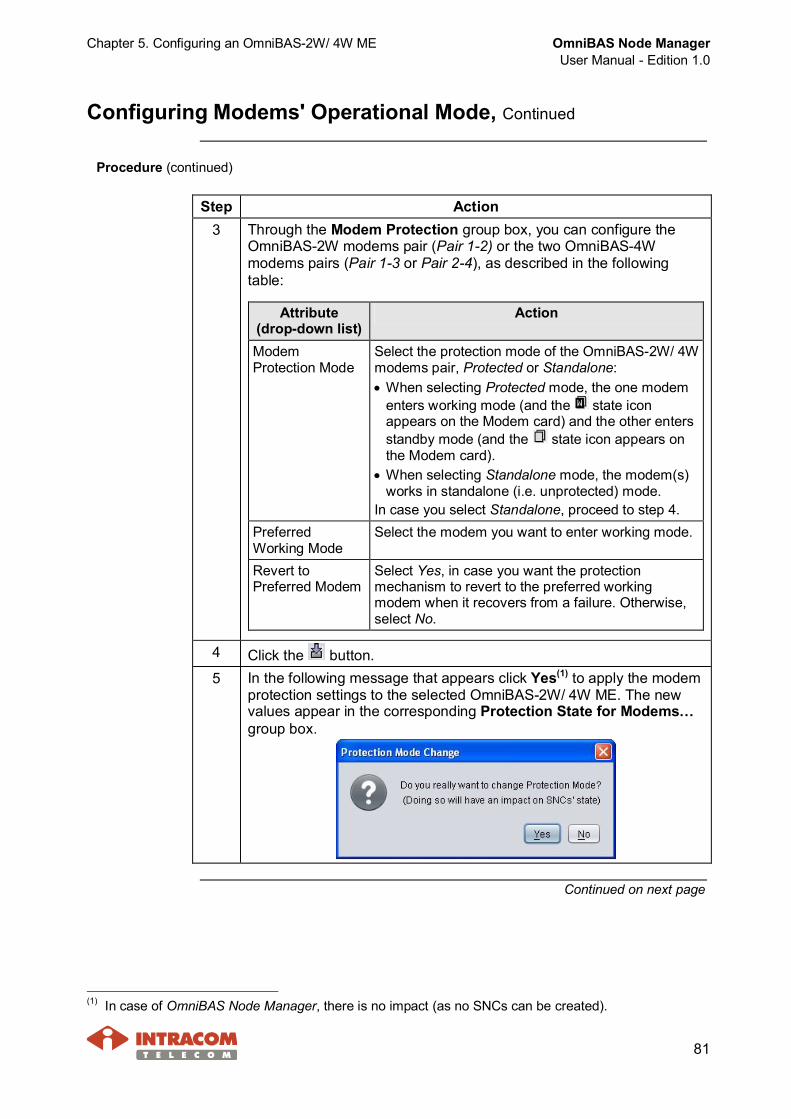
Chapter 5. Configuring an OmniBAS-2W/ 4W ME OmniBAS Node ManagerUser Manual - Edition 1.0
81
Configuring Modems' Operational Mode, Continued
Procedure (continued)
Step Action3 Through the Modem Protection group box, you can configure the
OmniBAS-2W modems pair (Pair 1-2) or the two OmniBAS-4Wmodems pairs (Pair 1-3 or Pair 2-4), as described in the followingtable:
Attribute(drop-down list)
Action
ModemProtection Mode
Select the protection mode of the OmniBAS-2W/ 4Wmodems pair, Protected or Standalone:· When selecting Protected mode, the one modem
enters working mode (and the state iconappears on the Modem card) and the other entersstandby mode (and the state icon appears onthe Modem card).
· When selecting Standalone mode, the modem(s)works in standalone (i.e. unprotected) mode.
In case you select Standalone, proceed to step 4.PreferredWorking Mode
Select the modem you want to enter working mode.
Revert toPreferred Modem
Select Yes, in case you want the protectionmechanism to revert to the preferred workingmodem when it recovers from a failure. Otherwise,select No.
4 Click the button.5 In the following message that appears click Yes(1) to apply the modem
protection settings to the selected OmniBAS-2W/ 4W ME. The newvalues appear in the corresponding Protection State for Modems…group box.
Continued on next page
(1) In case of OmniBAS Node Manager, there is no impact (as no SNCs can be created).
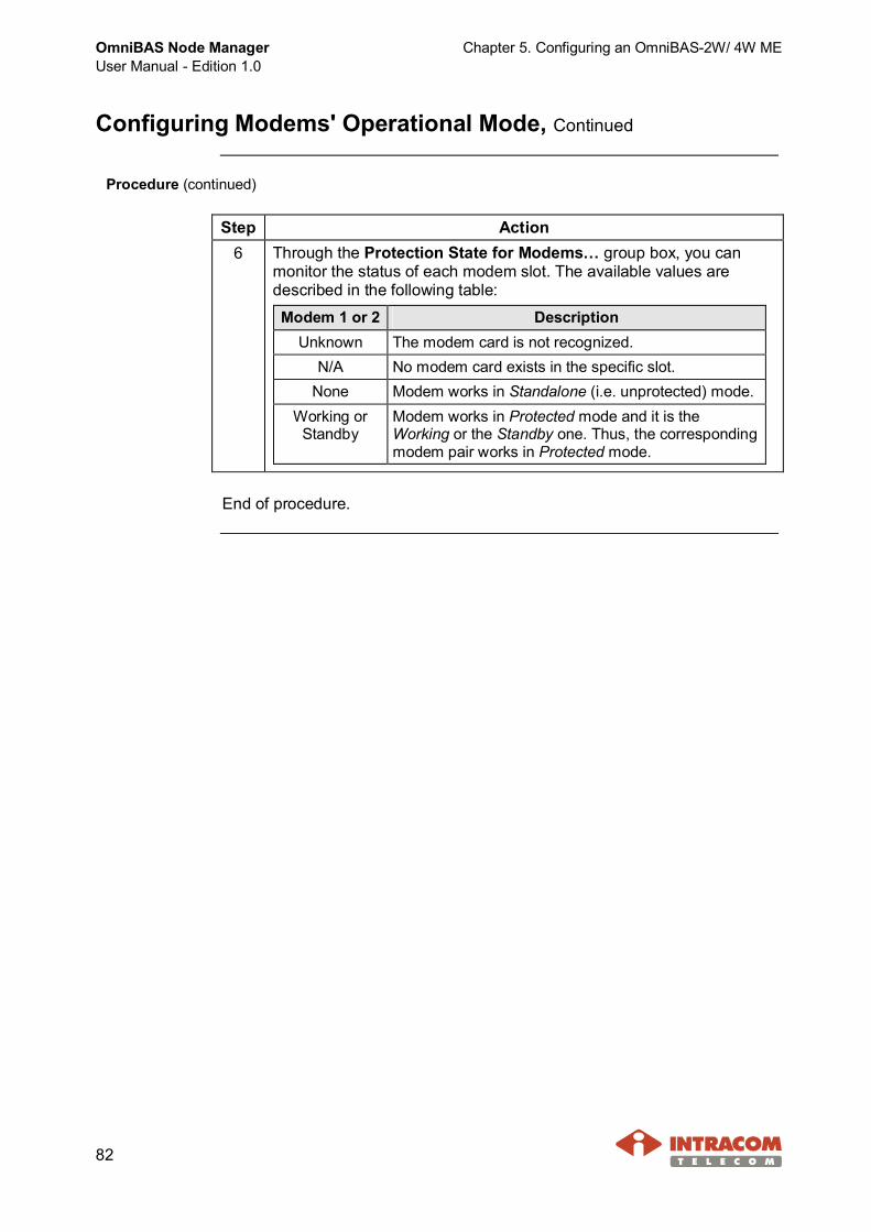
OmniBAS Node ManagerUser Manual - Edition 1.0
Chapter 5. Configuring an OmniBAS-2W/ 4W ME
82
Configuring Modems' Operational Mode, Continued
Procedure (continued)
Step Action6 Through the Protection State for Modems… group box, you can
monitor the status of each modem slot. The available values aredescribed in the following table:
Modem 1 or 2 DescriptionUnknown The modem card is not recognized.
N/A No modem card exists in the specific slot.None Modem works in Standalone (i.e. unprotected) mode.
Working orStandby
Modem works in Protected mode and it is theWorking or the Standby one. Thus, the correspondingmodem pair works in Protected mode.
End of procedure.
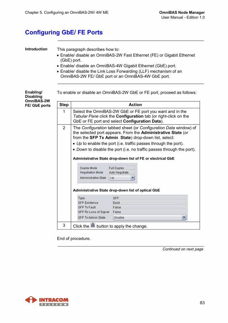
Chapter 5. Configuring an OmniBAS-2W/ 4W ME OmniBAS Node ManagerUser Manual - Edition 1.0
83
Configuring GbE/ FE Ports
Introduction This paragraph describes how to:· Enable/ disable an OmniBAS-2W Fast Ethernet (FE) or Gigabit Ethernet
(GbE) port.· Enable/ disable an OmniBAS-4W Gigabit Ethernet (GbE) port.· Enable/ disable the Link Loss Forwarding (LLF) mechanism of an
OmniBAS-2W FE/ GbE port or an OmniBAS-4W GbE port.
Enabling/DisablingOmniBAS-2WFE/ GbE ports
To enable or disable an OmniBAS-2W GbE or FE port, proceed as follows:
Step Action1 Select the OmniBAS-2W GbE or FE port you want and in the
Tabular Pane click the Configuration tab (or right-click on theGbE or FE port and select Configuration Data).
2 The Configuration tabbed sheet (or Configuration Data window) ofthe selected port appears. From the Administrative State (orfrom the SFP Tx Admin State) drop-down list, select:· Up to enable the port (i.e. traffic passes through the port).· Down to disable the port (i.e. no traffic passes through the port).
Administrative State drop-down list of FE or electrical GbE
Administrative State drop-down list of optical GbE
3 Click the button to apply the change.
End of procedure.
Continued on next page

OmniBAS Node ManagerUser Manual - Edition 1.0
Chapter 5. Configuring an OmniBAS-2W/ 4W ME
84
Configuring GbE/ FE Ports, Continued
Enabling/DisablingOmniBAS-4WGbE ports
To enable or disable an OmniBAS-4W GbE port, proceed as follows:
Step Action1 Select the OmniBAS-4W GbE port you want and in the Tabular
Pane click the Configuration tab (or right-click on the GbE portand select Configuration Data).
2 The Configuration tabbed sheet (or Configuration Data window) ofthe selected port appears. From the Administrative State (orfrom the SFP Tx Admin State) drop-down list, select:· Up to enable the port (i.e. traffic passes through the port).· Down to disable the port (i.e. no traffic passes through the port).
Administrative State drop-down list of electrical GbE
Administrative State drop-down list of optical GbE
3 Click the button to apply the change.
End of procedure.
Continued on next page
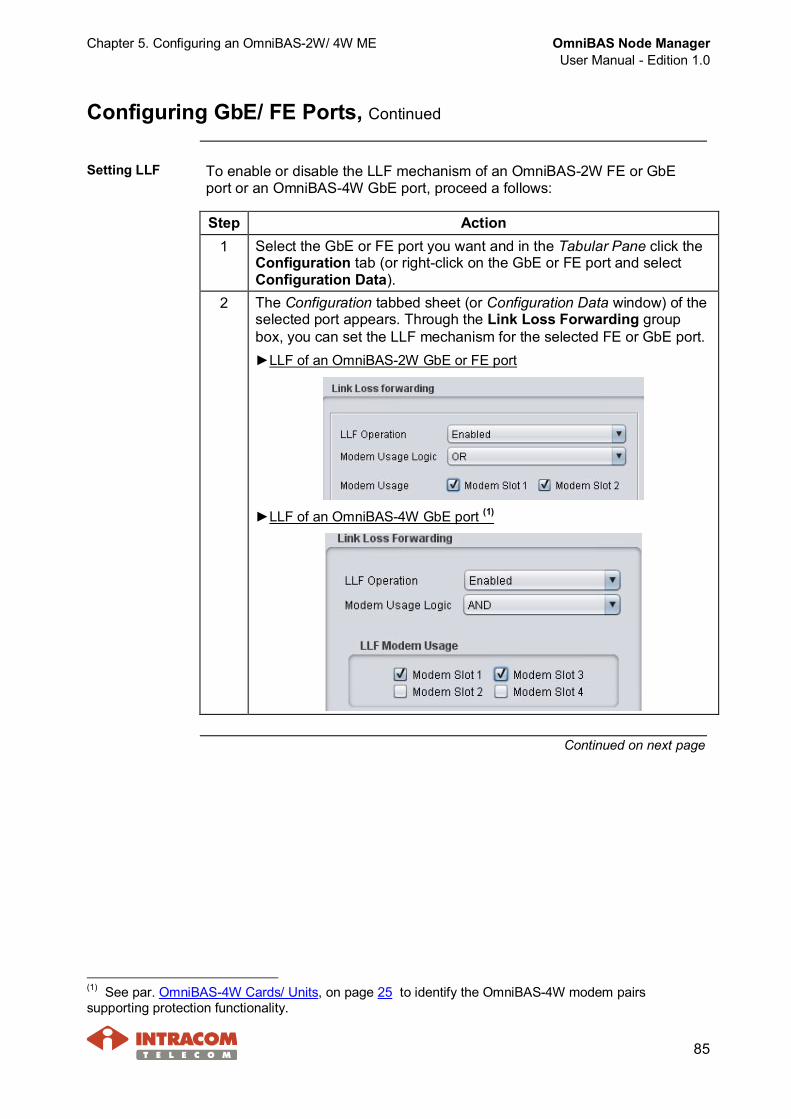
Chapter 5. Configuring an OmniBAS-2W/ 4W ME OmniBAS Node ManagerUser Manual - Edition 1.0
85
Configuring GbE/ FE Ports, Continued
Setting LLF To enable or disable the LLF mechanism of an OmniBAS-2W FE or GbEport or an OmniBAS-4W GbE port, proceed a follows:
Step Action1 Select the GbE or FE port you want and in the Tabular Pane click the
Configuration tab (or right-click on the GbE or FE port and selectConfiguration Data).
2 The Configuration tabbed sheet (or Configuration Data window) of theselected port appears. Through the Link Loss Forwarding groupbox, you can set the LLF mechanism for the selected FE or GbE port.►LLF of an OmniBAS-2W GbE or FE port
►LLF of an OmniBAS-4W GbE port (1)
Continued on next page
(1) See par. OmniBAS-4W Cards/ Units, on page 25 to identify the OmniBAS-4W modem pairssupporting protection functionality.
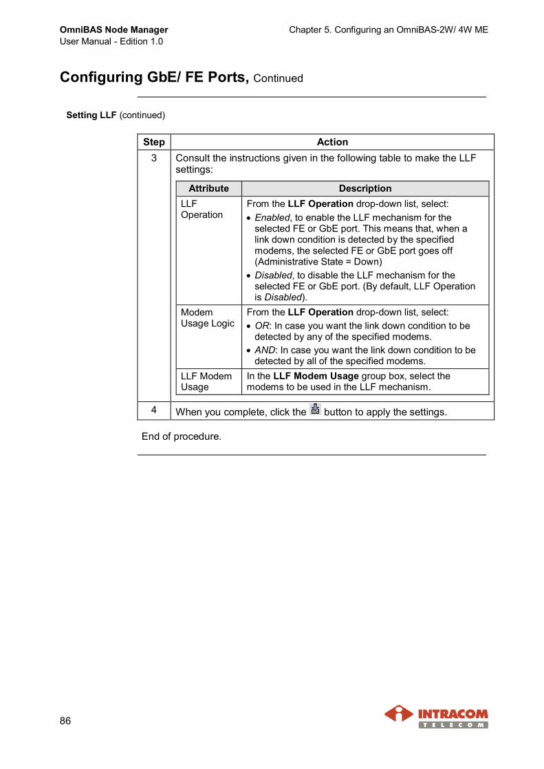
OmniBAS Node ManagerUser Manual - Edition 1.0
Chapter 5. Configuring an OmniBAS-2W/ 4W ME
86
Configuring GbE/ FE Ports, Continued
Setting LLF (continued)
Step Action3 Consult the instructions given in the following table to make the LLF
settings:
Attribute DescriptionLLFOperation
From the LLF Operation drop-down list, select:· Enabled, to enable the LLF mechanism for the
selected FE or GbE port. This means that, when alink down condition is detected by the specifiedmodems, the selected FE or GbE port goes off(Administrative State = Down)
· Disabled, to disable the LLF mechanism for theselected FE or GbE port. (By default, LLF Operationis Disabled).
ModemUsage Logic
From the LLF Operation drop-down list, select:· OR: In case you want the link down condition to be
detected by any of the specified modems.· AND: In case you want the link down condition to be
detected by all of the specified modems.LLF ModemUsage
In the LLF Modem Usage group box, select themodems to be used in the LLF mechanism.
4 When you complete, click the button to apply the settings.
End of procedure.

Chapter 5. Configuring an OmniBAS-2W/ 4W ME OmniBAS Node ManagerUser Manual - Edition 1.0
87
Configuring the E1 Ports
Introduction This paragraph describes how to:· Define the frame type of an OmniBAS-2W/ 4W E1 port.· Enable or disable an OmniBAS-2W/ 4W E1 port.
Procedure To configure an E1 port of an OmniBAS-2W/ 4W ME, proceed as follows:
Step Action1 Select the E1 port you want and in the Tabular Pane click the
Configuration tab (or right-click on the E1 port and selectConfiguration Data).
2 The Configuration tabbed sheet (or Configuration Data window) ofthe selected E1 port appears:
Continued on next page
OmniBAS Node ManagerUser Manual - Edition 1.0
Chapter 5. Configuring an OmniBAS-2W/ 4W ME
88
Configuring the E1 Ports, Continued
Procedure (continued)
Step Action3 To define the frame type of the E1 port, from the Frame Type
drop-down list, select:· Unstructured: Unstructured E1 provides stream of bits at 2048 kbit/s (no
framing support, i.e. no channels association with any specific group ofbits).
· Doubleframe (No signaling):- G.704 structured (consist of two standard-32 timeslots frames).- Timeslots TS1 to TS31 transfer payload. Frame synchronization is
carried over timeslot TS0.- No payload signaling is used.
· Multiframe - CRC (No signaling):- G.704 structured (consist of 16 standard-32 timeslots frames).- Timeslots TS1 to TS31 transfer payload. Frame synchronization is
carried over timeslot TS0.- No payload signaling is used.- The Si bits of each Frame Alignment Signal (FAS) are used to
implement CRC-4 control.
NOTE You cannot change the frame type of an E1 port that isassociated with a connection.
4 To enable the E1 port (i.e. traffic passes through the E1 port), selectEnable from the Admin State drop-down list.To disable the E1 port (i.e. no traffic passes through the E1 port),select Disable from the Admin State drop-down list.
5 Click the button to apply the settings on the E1 port.
End of procedure.

Chapter 5. Configuring an OmniBAS-2W/ 4W ME OmniBAS Node ManagerUser Manual - Edition 1.0
89
5.3 Configuring Modem Parameters
Introduction This paragraph describes how to set the channel bandwidth, theconfiguration profile, the ACM / ATPC features and the physical modulationprofile of an OmniBAS-2W/ 4W modem.
NOTE To configure an OmniBAS-2W/ 4W radio link, perform theprocedure provided in this paragraph to both modems of the link(local and remote).
When you change the configuration of an OmniBAS-2W/ 4Wmodem, link downtime is caused. For this reason:· Select a convenient time for changing the configuration of
the modem.· Start with the configuration of the remote modem.
Otherwise, communication loss with the remote modem willtake place and a visit to the site will be required.
The configuration of an OmniBAS-2W/ 4W modem must bemade only by qualified personnel and according the RFplanning.
Continued on next page
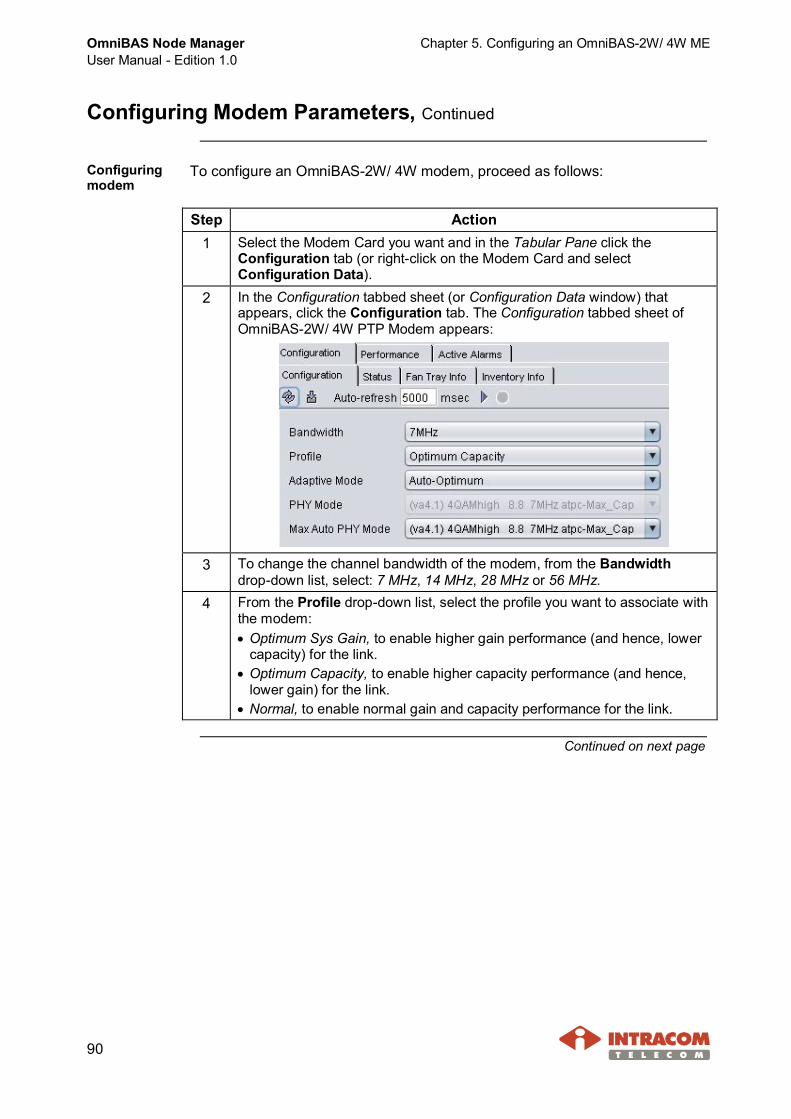
OmniBAS Node ManagerUser Manual - Edition 1.0
Chapter 5. Configuring an OmniBAS-2W/ 4W ME
90
Configuring Modem Parameters, Continued
Configuringmodem
To configure an OmniBAS-2W/ 4W modem, proceed as follows:
Step Action1 Select the Modem Card you want and in the Tabular Pane click the
Configuration tab (or right-click on the Modem Card and selectConfiguration Data).
2 In the Configuration tabbed sheet (or Configuration Data window) thatappears, click the Configuration tab. The Configuration tabbed sheet ofOmniBAS-2W/ 4W PTP Modem appears:
3 To change the channel bandwidth of the modem, from the Bandwidthdrop-down list, select: 7 MHz, 14 MHz, 28 MHz or 56 MHz.
4 From the Profile drop-down list, select the profile you want to associate withthe modem:· Optimum Sys Gain, to enable higher gain performance (and hence, lower
capacity) for the link.· Optimum Capacity, to enable higher capacity performance (and hence,
lower gain) for the link.· Normal, to enable normal gain and capacity performance for the link.
Continued on next page

Chapter 5. Configuring an OmniBAS-2W/ 4W ME OmniBAS Node ManagerUser Manual - Edition 1.0
91
Configuring Modem Parameters, Continued
Configuring modem (continued)
Step Action5 From Adaptive Mode drop-down list, select one of the following options:
AdaptiveMode option
Description
Manual To enable the manual modulation mode and also tomanual assign the Tx power level. In this case, themodem will use the modulation mode that you will assignthrough the PHY Mode drop-down list. Also, the modemwill use the Tx power level that you will assign throughthe Set Tx Power text box (in the Configuration tab ofthe corresponding ODU).
Auto/ ManualPower
To enable the adaptive modulation mode(1) and also tomanual assign the Tx power level.The upper limit of the Tx power is specified by themaximum Tx power per modulation (that you will selectthrough the MAX Auto PHY Mode drop-down list).The lower limit of the Tx power selection is fixed to Txpower provided by the lowest modulation mode (i.e. bythe 4QAM-high).
Auto/Optimum
To enable the adaptive modulation mode(1) and also theoptimum Tx power per modulation.You will define the upper level of the modulation, throughthe MAX Auto PHY Mode drop-down list.In any case, the system will select a combination ofoptimum Tx power and modulation.
Auto/Max Power
To enable the adaptive modulation mode(1) and also themaximum available Tx power per modulation.You will define the upper level of the modulation, throughthe MAX Auto PHY Mode drop-down list.When the link has a transition from a modulation mode toa less efficient one, the Tx power change to its maximumvalue is immediate.
Continued on next page
(1) When the ACM (Adaptive Coding & Modulation) feature is enabled, the modem automatically adjuststhe modulation mode (from 256 QAM to 4 QAM and vice versa) in response to weather/ link conditions.
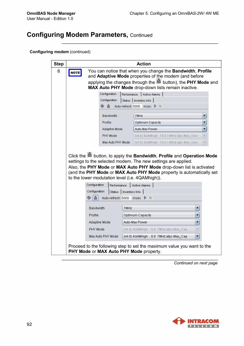
OmniBAS Node ManagerUser Manual - Edition 1.0
Chapter 5. Configuring an OmniBAS-2W/ 4W ME
92
Configuring Modem Parameters, Continued
Configuring modem (continued)
Step Action6 NOTE You can notice that when you change the Bandwidth, Profile
and Adaptive Mode properties of the modem (and beforeapplying the changes through the button), the PHY Mode andMAX Auto PHY Mode drop-down lists remain inactive.
Click the button, to apply the Bandwidth, Profile and Operation Modesettings to the selected modem. The new settings are applied.Also, the PHY Mode or MAX Auto PHY Mode drop-down list is activated(and the PHY Mode or MAX Auto PHY Mode property is automatically setto the lower modulation level (i.e. 4QAMhigh)).
Proceed to the following step to set the maximum value you want to thePHY Mode or MAX Auto PHY Mode property.
Continued on next page

Chapter 5. Configuring an OmniBAS-2W/ 4W ME OmniBAS Node ManagerUser Manual - Edition 1.0
93
Configuring Modem Parameters, Continued
Configuring modem (continued)
Step Action7 · For Adaptive Mode = Manual, the corresponding modulation modes
are activated in the PHY Mode drop-down list.From thisdrop-down list,select themodulation modeyou want to assignto the modem.
· For Adaptive Mode = Auto-Manual Power, Auto-Optimum orAuto-Max Power, the corresponding modulation modes are activatedin the Max Auto PHY Mode drop-down list.
From thisdrop-down list,select themaximummodulation modeyou want to assignto the modem.
· Click the button, to apply the modulation mode to the selectedmodem(1).
End of procedure.
(1) In case of Manual mode, after you assign the modulation mode, you must also set the transmit power,as described in par. Setting Tx Frequency and Tx Power, on page 96.

OmniBAS Node ManagerUser Manual - Edition 1.0
Chapter 5. Configuring an OmniBAS-2W/ 4W ME
94
5.4 Configuring ODU Parameters
This section provides the following procedures for configuring an OmniBAS-2W/4W ODU:· Enabling/ Disabling ODU Mute & DC Power· Setting Tx Frequency and Tx Power· Setting RSSI & Temperature Alarm Thresholds· Setting Update Mode of ODU

Chapter 5. Configuring an OmniBAS-2W/ 4W ME OmniBAS Node ManagerUser Manual - Edition 1.0
95
Enabling/ Disabling ODU Mute & DC Power
Introduction This paragraph describes how to enable/ disable the mute and the DC powerof an ODU.
Procedure To enable/ disable the mute or the DC power of an ODU, proceed as follows:
Be very careful when you change the settings of anOmniBAS-2W/ 4W ODU, because link downtime may becaused. Thus, select to change the configuration settings ofthe ODU at a convenient time.
Step Action1 Select the ODU you want and in the Tabular Pane click the
Configuration tab (or right-click on the ODU and selectConfiguration Data).
2 In the Configurationtabbed sheet (orConfiguration Datawindow) that appears,click the Configurationtab.
3 From the Mute drop-down list, select:· ON (1), to mute the ODU. Muting an ODU results in transmission
interruption of the ODU.· OFF, to unmute the ODU.
4 From the DC Power drop-down list, select:· ON, to enable the power up of the selected ODU.· OFF (1), to enable the power down of the selected ODU.
5 When you finish, click the button, to apply the change(s) to theselected ODU.
End of procedure.
(1) Default value.

OmniBAS Node ManagerUser Manual - Edition 1.0
Chapter 5. Configuring an OmniBAS-2W/ 4W ME
96
Setting Tx Frequency and Tx Power
Introduction This paragraph describes how to set the Tx frequency and the Tx power of anODU.
NOTETo configure an OmniBAS-2W/ 4W radio link, perform the proceduresprovided in this paragraph to both ODUs (local and remote) of the link.
Changes on the ODU configuration must be made only byqualified personnel and according the RF planning.
When you change the Tx frequency and Tx power of theOmniBAS-2W/ 4W ODUs, link downtime is caused. For this reason:· Select a convenient time for making the ODU changes.· Start with the configuration change of the remote ODU.
Otherwise, communication loss with the remote ODU will takeplace and a visit to the site will be required.
Procedure To set the Tx frequency (in kHz) and the Tx Power (in dBm) of the ODU,proceed as follows:
Step Action1 Select the ODU you want and in the Tabular Pane click the
Configuration tab (or right-click on the ODU and select ConfigurationData).
2 In the Configurationtabbed sheet (orConfiguration Datawindow) that appears,click the Configurationtab.
Continued on next page

Chapter 5. Configuring an OmniBAS-2W/ 4W ME OmniBAS Node ManagerUser Manual - Edition 1.0
97
Setting Tx Frequency and Tx Power, Continued
Procedure (continued)
Step Action3 In the Set Tx Frequency field, click the button.
The Suggested Frequency Valueswindow appears listing the availablefrequency values. The current Txfrequency is displayed red-colored.Note that the frequency values of thiswindow result from the First / LastFrequency and Frequency Step valuesthat are displayed in the Capabilitiestabbed sheet of the specific ODU.
4 To change the Tx frequency value, click the new one.The selectedvalue isautomaticallyentered in theSet TxFrequency field.
5 In the Set Tx Power textbox, type the new valuefor the power transmittedfrom the selected ODU.Note that you can see theupper and lowerthresholds of the Txpower in thecorresponding fields ofthe Capabilities tabbedsheet.
6 Click the button to apply the Tx frequency and Tx power values tothe selected ODU.
End of procedure.

OmniBAS Node ManagerUser Manual - Edition 1.0
Chapter 5. Configuring an OmniBAS-2W/ 4W ME
98
Setting RSSI & Temperature Alarm Thresholds
Introduction This paragraph describes how set the RSSI and Temperature alarm thresholdsof an ODU.
Procedure To set the RSSI and Temperature alarm thresholds of an ODU, proceed asfollows:
Step Action1 Select the ODU you want and in the Tabular Pane click the
Configuration tab (or right-click on the ODU and select ConfigurationData).
2 In the Configuration tabbedsheet (or Configuration Datawindow) that appears, click theConfiguration tab.The alarm thresholds can beset through the ODU AlarmConfiguration group box.
3 To set a new RSSI threshold, type the new one (absolute value) in theRSSI Threshold text box.RSSI threshold should range between -90 dBm and -30 dBm.
NOTE In case the current RSSI value(1) of the ODU exceeds thespecified threshold value, the ODU RSSI Rx Thresholdalarm (with ID = 14066 for OmniBAS-2W and 6066 forOmniBAS-4W) will be issued.
4 To set a new temperature upper threshold for the ODU, type the newone in the Temperature Threshold text box.Temperature threshold should range between 60ºC and 80ºC.
NOTE In case the current temperature(1) of the ODU exceeds thespecified threshold value, the ODU Max Temperaturealarm (with ID = 14062 for OmniBAS-2W and 6062 forOmniBAS-4W) will be issued.
5 Click the button to apply the new threshold(s).
End of procedure.
(1) The current Temperature and RSSI values of the ODU are displayed in the Analog Monitor tabbed sheet.

Chapter 5. Configuring an OmniBAS-2W/ 4W ME OmniBAS Node ManagerUser Manual - Edition 1.0
99
Setting Update Mode of ODU
Introduction This paragraph describes how to set the firmware update mode of an ODU.
Procedure To set the firmware update mode of the ODU, proceed as follows:
Step Action1 Select the ODU you want and in the Tabular Pane click the
Configuration tab (or right-click on the ODU and selectConfiguration Data).
2 In the Configuration tabbed sheet (or Configuration Data window)that appears, click the Configuration tab.
3 From the Auto Update Mode drop-down list, select:· Auto, to enable the automatic updating of the ODU. When
OmniBAS Node Manager detects that an ODU updating is required(e.g. after an ODU replacement), the corresponding messageappears in the Status tab(1) of the ODU. The ODU updatingprocess will take place, upon next ODU’s power up.
· Manual(2), to enable the manual updating of the ODU.
NOTE The Update Status of the ODU (Updated, Needs Update orUpdated Now) is displayed in the Status tabbed sheet (seepar. Status, on page 216).
4 Click the button to apply the change to the selected ODU.
End of procedure.
(1) See par. Status, on page 217.(2) Default value.

OmniBAS Node ManagerUser Manual - Edition 1.0
Chapter 6. Configuring OmniBAS-2W/ 4W Bridge Functionality
100
6 Configuring OmniBAS-2W/ 4W Bridge Functionality
This chapter provides the following step-by-step procedures to configure thebridge functionality of an OmniBAS-2W/ 4W ME:· Setting Bridge Parameters· Configuring L2 Ports· Configuring Ethernet QoS· Configuring Policer Parameters· Configuring Service Flows· Configuring Forwarding Process
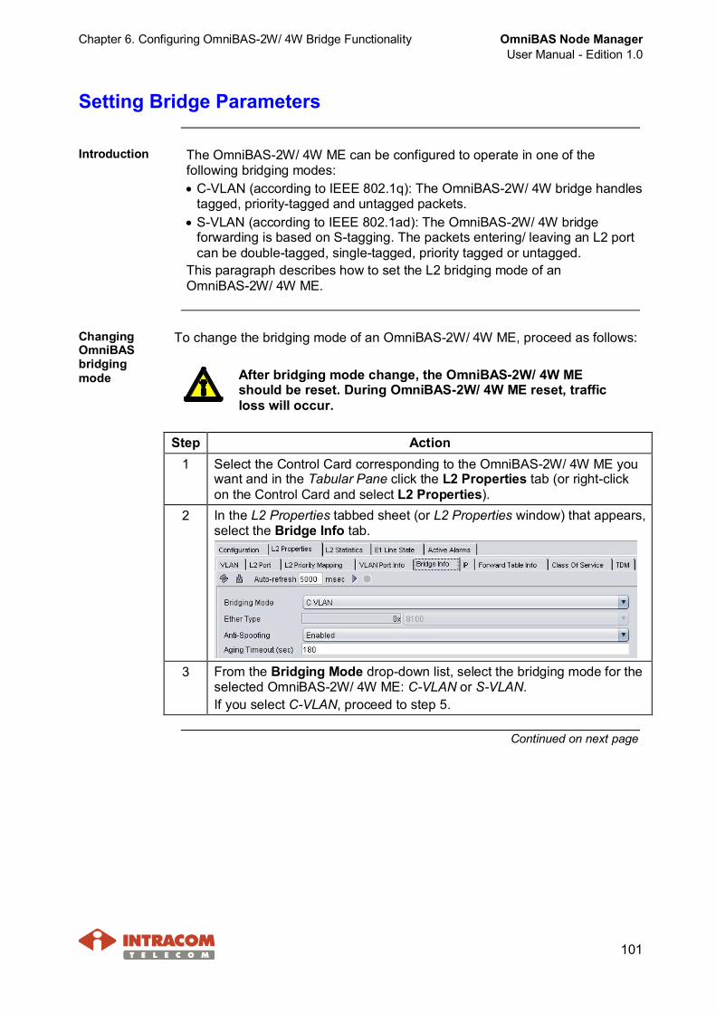
Chapter 6. Configuring OmniBAS-2W/ 4W Bridge Functionality OmniBAS Node ManagerUser Manual - Edition 1.0
101
Setting Bridge Parameters
Introduction The OmniBAS-2W/ 4W ME can be configured to operate in one of thefollowing bridging modes:· C-VLAN (according to IEEE 802.1q): The OmniBAS-2W/ 4W bridge handles
tagged, priority-tagged and untagged packets.· S-VLAN (according to IEEE 802.1ad): The OmniBAS-2W/ 4W bridge
forwarding is based on S-tagging. The packets entering/ leaving an L2 portcan be double-tagged, single-tagged, priority tagged or untagged.
This paragraph describes how to set the L2 bridging mode of anOmniBAS-2W/ 4W ME.
ChangingOmniBASbridgingmode
To change the bridging mode of an OmniBAS-2W/ 4W ME, proceed as follows:
After bridging mode change, the OmniBAS-2W/ 4W MEshould be reset. During OmniBAS-2W/ 4W ME reset, trafficloss will occur.
Step Action1 Select the Control Card corresponding to the OmniBAS-2W/ 4W ME you
want and in the Tabular Pane click the L2 Properties tab (or right-clickon the Control Card and select L2 Properties).
2 In the L2 Properties tabbed sheet (or L2 Properties window) that appears,select the Bridge Info tab.
3 From the Bridging Mode drop-down list, select the bridging mode for theselected OmniBAS-2W/ 4W ME: C-VLAN or S-VLAN.If you select C-VLAN, proceed to step 5.
Continued on next page
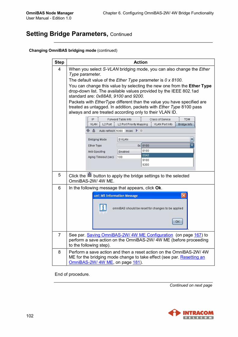
OmniBAS Node ManagerUser Manual - Edition 1.0
Chapter 6. Configuring OmniBAS-2W/ 4W Bridge Functionality
102
Setting Bridge Parameters, Continued
Changing OmniBAS bridging mode (continued)
Step Action4 When you select S-VLAN bridging mode, you can also change the Ether
Type parameter.The default value of the Ether Type parameter is 0 x 8100.You can change this value by selecting the new one from the Ether Typedrop-down list. The available values provided by the IEEE 802.1adstandard are: 0x88A8, 9100 and 9200.Packets with EtherType different than the value you have specified aretreated as untagged. In addition, packets with Ether Type 8100 passalways and are treated according only to their VLAN ID.
5 Click the button to apply the bridge settings to the selectedOmniBAS-2W/ 4W ME.
6 In the following message that appears, click Ok.
.7 See par. Saving OmniBAS-2W/ 4W ME Configuration (on page 167) to
perform a save action on the OmniBAS-2W/ 4W ME (before proceedingto the following step).
8 Perform a save action and then a reset action on the OmniBAS-2W/ 4WME for the bridging mode change to take effect (see par. Resetting anOmniBAS-2W/ 4W ME, on page 181).
End of procedure.
Continued on next page
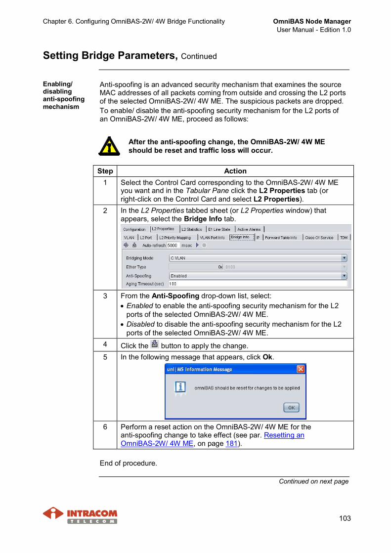
Chapter 6. Configuring OmniBAS-2W/ 4W Bridge Functionality OmniBAS Node ManagerUser Manual - Edition 1.0
103
Setting Bridge Parameters, Continued
Enabling/disablinganti-spoofingmechanism
Anti-spoofing is an advanced security mechanism that examines the sourceMAC addresses of all packets coming from outside and crossing the L2 portsof the selected OmniBAS-2W/ 4W ME. The suspicious packets are dropped.To enable/ disable the anti-spoofing security mechanism for the L2 ports ofan OmniBAS-2W/ 4W ME, proceed as follows:
After the anti-spoofing change, the OmniBAS-2W/ 4W MEshould be reset and traffic loss will occur.
Step Action1 Select the Control Card corresponding to the OmniBAS-2W/ 4W ME
you want and in the Tabular Pane click the L2 Properties tab (orright-click on the Control Card and select L2 Properties).
2 In the L2 Properties tabbed sheet (or L2 Properties window) thatappears, select the Bridge Info tab.
3 From the Anti-Spoofing drop-down list, select:· Enabled to enable the anti-spoofing security mechanism for the L2
ports of the selected OmniBAS-2W/ 4W ME.· Disabled to disable the anti-spoofing security mechanism for the L2
ports of the selected OmniBAS-2W/ 4W ME.4 Click the button to apply the change.5 In the following message that appears, click Ok.
6 Perform a reset action on the OmniBAS-2W/ 4W ME for theanti-spoofing change to take effect (see par. Resetting anOmniBAS-2W/ 4W ME, on page 181).
End of procedure.
Continued on next page
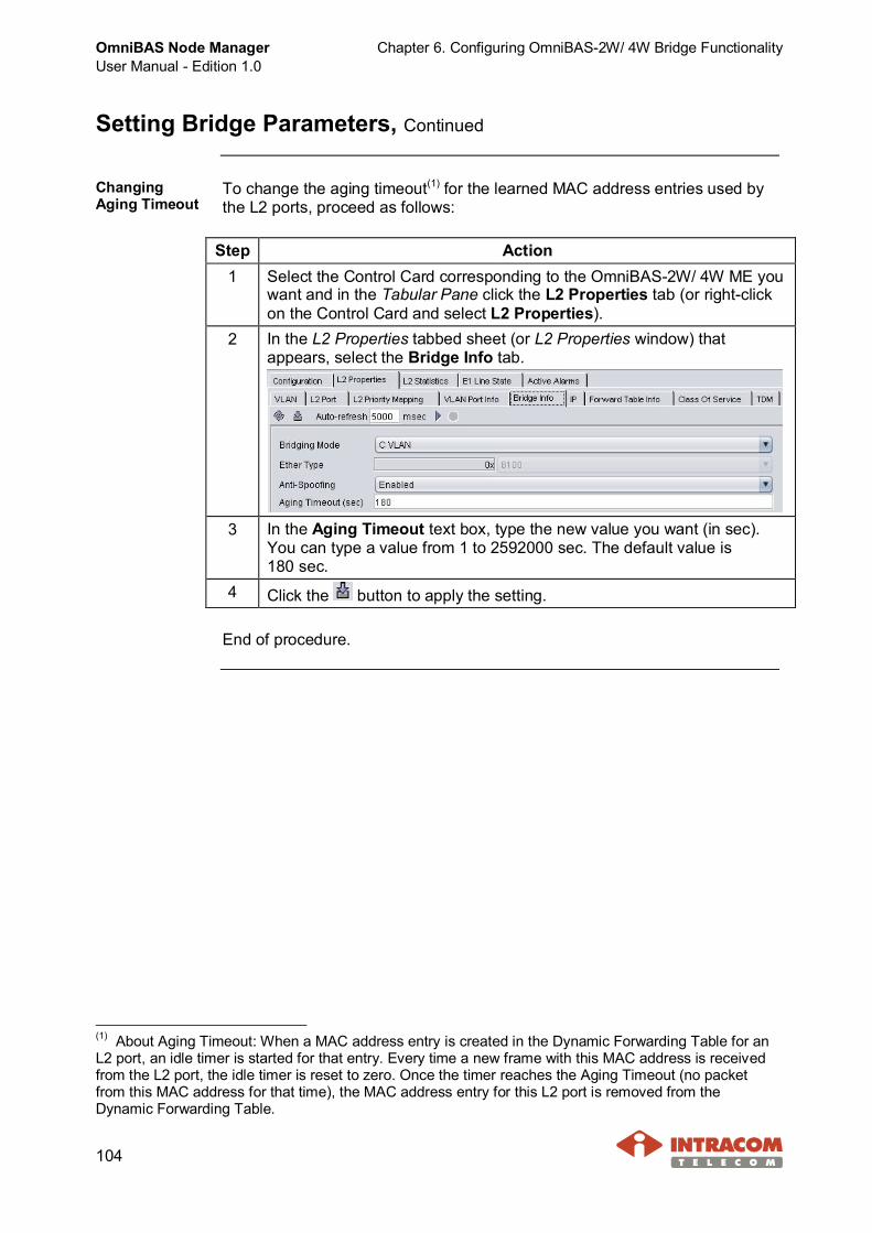
OmniBAS Node ManagerUser Manual - Edition 1.0
Chapter 6. Configuring OmniBAS-2W/ 4W Bridge Functionality
104
Setting Bridge Parameters, Continued
ChangingAging Timeout
To change the aging timeout(1) for the learned MAC address entries used bythe L2 ports, proceed as follows:
Step Action1 Select the Control Card corresponding to the OmniBAS-2W/ 4W ME you
want and in the Tabular Pane click the L2 Properties tab (or right-clickon the Control Card and select L2 Properties).
2 In the L2 Properties tabbed sheet (or L2 Properties window) thatappears, select the Bridge Info tab.
3 In the Aging Timeout text box, type the new value you want (in sec).You can type a value from 1 to 2592000 sec. The default value is180 sec.
4 Click the button to apply the setting.
End of procedure.
(1) About Aging Timeout: When a MAC address entry is created in the Dynamic Forwarding Table for anL2 port, an idle timer is started for that entry. Every time a new frame with this MAC address is receivedfrom the L2 port, the idle timer is reset to zero. Once the timer reaches the Aging Timeout (no packetfrom this MAC address for that time), the MAC address entry for this L2 port is removed from theDynamic Forwarding Table.
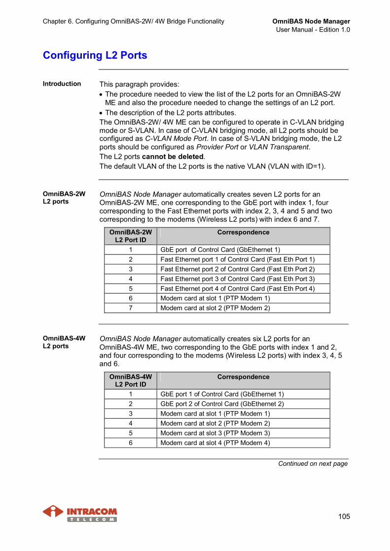
Chapter 6. Configuring OmniBAS-2W/ 4W Bridge Functionality OmniBAS Node ManagerUser Manual - Edition 1.0
105
Configuring L2 Ports
Introduction This paragraph provides:· The procedure needed to view the list of the L2 ports for an OmniBAS-2W
ME and also the procedure needed to change the settings of an L2 port.· The description of the L2 ports attributes.The OmniBAS-2W/ 4W ME can be configured to operate in C-VLAN bridgingmode or S-VLAN. In case of C-VLAN bridging mode, all L2 ports should beconfigured as C-VLAN Mode Port. In case of S-VLAN bridging mode, the L2ports should be configured as Provider Port or VLAN Transparent.The L2 ports cannot be deleted.The default VLAN of the L2 ports is the native VLAN (VLAN with ID=1).
OmniBAS-2WL2 ports
OmniBAS Node Manager automatically creates seven L2 ports for anOmniBAS-2W ME, one corresponding to the GbE port with index 1, fourcorresponding to the Fast Ethernet ports with index 2, 3, 4 and 5 and twocorresponding to the modems (Wireless L2 ports) with index 6 and 7.
OmniBAS-2WL2 Port ID
Correspondence
1 GbE port of Control Card (GbEthernet 1)2 Fast Ethernet port 1 of Control Card (Fast Eth Port 1)3 Fast Ethernet port 2 of Control Card (Fast Eth Port 2)4 Fast Ethernet port 3 of Control Card (Fast Eth Port 3)5 Fast Ethernet port 4 of Control Card (Fast Eth Port 4)6 Modem card at slot 1 (PTP Modem 1)7 Modem card at slot 2 (PTP Modem 2)
OmniBAS-4WL2 ports
OmniBAS Node Manager automatically creates six L2 ports for anOmniBAS-4W ME, two corresponding to the GbE ports with index 1 and 2,and four corresponding to the modems (Wireless L2 ports) with index 3, 4, 5and 6.
OmniBAS-4WL2 Port ID
Correspondence
1 GbE port 1 of Control Card (GbEthernet 1)2 GbE port 2 of Control Card (GbEthernet 2)3 Modem card at slot 1 (PTP Modem 1)4 Modem card at slot 2 (PTP Modem 2)5 Modem card at slot 3 (PTP Modem 3)6 Modem card at slot 4 (PTP Modem 4)
Continued on next page

OmniBAS Node ManagerUser Manual - Edition 1.0
Chapter 6. Configuring OmniBAS-2W/ 4W Bridge Functionality
106
Configuring L2 Ports, Continued
Changing L2ports settings
To view or change the L2 ports settings of an OmniBAS-2W/ 4W ME,proceed as follows:
Step Action1 Select the Control Card corresponding to the OmniBAS-2W/ 4W ME
you want and in the Tabular Pane click the L2 Properties tab (orright-click on the Control Card and select L2 Properties).
2 In the L2 Properties tabbed sheet (or L2 Properties window) thatappears, select the L2 Port tab.► L2 Port tabbed sheet of OmniBAS-2W ME
The L2 Port tabbed sheet displays the seven L2 ports of theOmniBAS-2W ME together with their attributes.► L2 Port tabbed sheet of OmniBAS-4W ME
The L2 Port tabbed sheet displays the six L2 ports of the OmniBAS-4WME together with their attributes.
Continued on next page
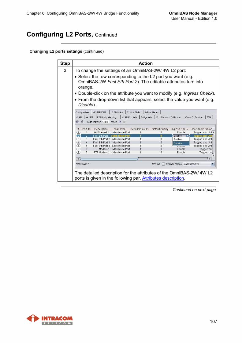
Chapter 6. Configuring OmniBAS-2W/ 4W Bridge Functionality OmniBAS Node ManagerUser Manual - Edition 1.0
107
Configuring L2 Ports, Continued
Changing L2 ports settings (continued)
Step Action3 To change the settings of an OmniBAS-2W/ 4W L2 port:
· Select the row corresponding to the L2 port you want (e.g.OmniBAS-2W Fast Eth Port 2). The editable attributes turn intoorange.
· Double-click on the attribute you want to modify (e.g. Ingress Check).· From the drop-down list that appears, select the value you want (e.g.
Disable).
The detailed description for the attributes of the OmniBAS-2W/ 4W L2ports is given in the following par. Attributes description.
Continued on next page
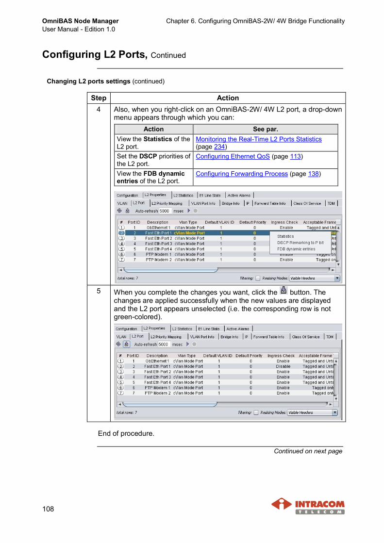
OmniBAS Node ManagerUser Manual - Edition 1.0
Chapter 6. Configuring OmniBAS-2W/ 4W Bridge Functionality
108
Configuring L2 Ports, Continued
Changing L2 ports settings (continued)
Step Action4 Also, when you right-click on an OmniBAS-2W/ 4W L2 port, a drop-down
menu appears through which you can:Action See par.
View the Statistics of theL2 port.
Monitoring the Real-Time L2 Ports Statistics(page 234)
Set the DSCP priorities ofthe L2 port.
Configuring Ethernet QoS (page 113)
View the FDB dynamicentries of the L2 port.
Configuring Forwarding Process (page 138)
5 When you complete the changes you want, click the button. Thechanges are applied successfully when the new values are displayedand the L2 port appears unselected (i.e. the corresponding row is notgreen-colored).
End of procedure.
Continued on next page
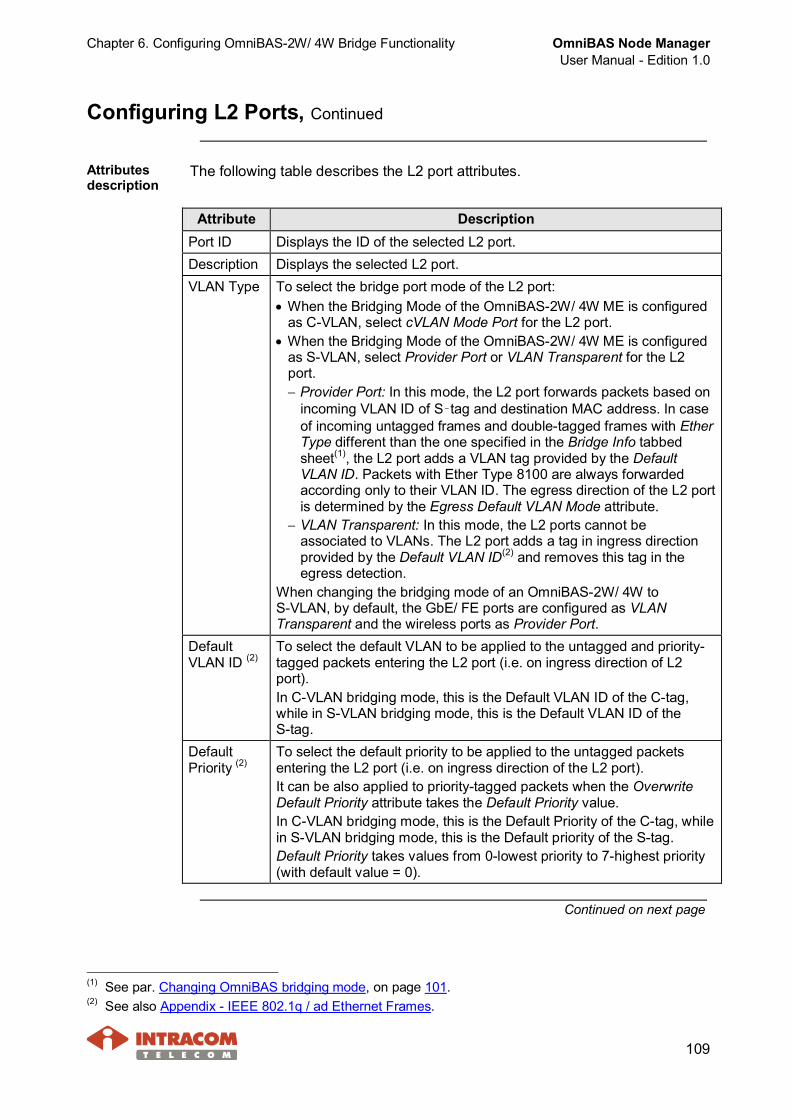
Chapter 6. Configuring OmniBAS-2W/ 4W Bridge Functionality OmniBAS Node ManagerUser Manual - Edition 1.0
109
Configuring L2 Ports, Continued
Attributesdescription
The following table describes the L2 port attributes.
Attribute DescriptionPort ID Displays the ID of the selected L2 port.Description Displays the selected L2 port.VLAN Type To select the bridge port mode of the L2 port:
· When the Bridging Mode of the OmniBAS-2W/ 4W ME is configuredas C-VLAN, select cVLAN Mode Port for the L2 port.
· When the Bridging Mode of the OmniBAS-2W/ 4W ME is configuredas S-VLAN, select Provider Port or VLAN Transparent for the L2port.- Provider Port: In this mode, the L2 port forwards packets based on
incoming VLAN ID of S‑tag and destination MAC address. In caseof incoming untagged frames and double-tagged frames with EtherType different than the one specified in the Bridge Info tabbedsheet(1), the L2 port adds a VLAN tag provided by the DefaultVLAN ID. Packets with Ether Type 8100 are always forwardedaccording only to their VLAN ID. The egress direction of the L2 portis determined by the Egress Default VLAN Mode attribute.
- VLAN Transparent: In this mode, the L2 ports cannot beassociated to VLANs. The L2 port adds a tag in ingress directionprovided by the Default VLAN ID(2) and removes this tag in theegress detection.
When changing the bridging mode of an OmniBAS-2W/ 4W toS-VLAN, by default, the GbE/ FE ports are configured as VLANTransparent and the wireless ports as Provider Port.
DefaultVLAN ID (2)
To select the default VLAN to be applied to the untagged and priority-tagged packets entering the L2 port (i.e. on ingress direction of L2port).In C-VLAN bridging mode, this is the Default VLAN ID of the C-tag,while in S-VLAN bridging mode, this is the Default VLAN ID of theS-tag.
DefaultPriority (2)
To select the default priority to be applied to the untagged packetsentering the L2 port (i.e. on ingress direction of the L2 port).It can be also applied to priority-tagged packets when the OverwriteDefault Priority attribute takes the Default Priority value.In C-VLAN bridging mode, this is the Default Priority of the C-tag, whilein S-VLAN bridging mode, this is the Default priority of the S-tag.Default Priority takes values from 0-lowest priority to 7-highest priority(with default value = 0).
Continued on next page
(1) See par. Changing OmniBAS bridging mode, on page 101.(2) See also Appendix - IEEE 802.1q / ad Ethernet Frames.

OmniBAS Node ManagerUser Manual - Edition 1.0
Chapter 6. Configuring OmniBAS-2W/ 4W Bridge Functionality
110
Configuring L2 Ports, Continued
Attributes description (continued)
Attribute DescriptionIngressCheck
To enable or disable the ingress filtering of the L2 port. When selecting:· Enable – The L2 port accepts only the tagged frames that their VLAN(2)
are associated with this L2 port (VLAN Port Info tabbed sheet). Then,the packets are forwarded according to static and dynamic forwardingtables of the L2 port (Forward Table Info tabbed sheet).
· Disable – All tagged frames arriving to this L2 port are accepted. Then,the packets are forwarded according to static and dynamic forwardingtables of the L2 port (Forward Table Info tabbed sheet).
OverwriteDefaultPriority(3)
When you select:· Incoming C Tag Priority – The Incoming Tag Priority of the tagged and
priority-tagged packets entering the L2 port does not change.· Default Priority – The Incoming C Tag Priority of the tagged and priority
tagged packets entering the L2 port is changed by the Default Priority ofthe port.
Continued on next page
(2) i.e. the Default VLAN ID of C-tag in case of C-VLAN Bridging Mode and the Default VLAN ID of S-tagin case of S-VLAN Bridging Mode (that you can also find it as Outer VLAN ID).(3) This attribute affects only the OmniBAS-2W ME (i.e. the tagged ETH frames entering OmniBAS-4Wbridge are unaffected from this attribute).

Chapter 6. Configuring OmniBAS-2W/ 4W Bridge Functionality OmniBAS Node ManagerUser Manual - Edition 1.0
111
Configuring L2 Ports, Continued
Attributes description (continued)
Attribute DescriptionAcceptableFrameType
To select the ETH frame types to be accepted by the L2 port.
Then:If you select one of thefollowing AcceptableFrame Type option:
Untagged Prioritytagged
Singletagged
Doubletagged
C-VLAN Bridging Mode· Untagged Only Accepted Accepted Dropped Dropped· Tagged Only Dropped Dropped Accepted Accepted· Tagged and Untagged Accepted Accepted Accepted Accepted· Accept None Dropped Dropped Dropped Dropped
S-VLAN Bridging Mode - Provider Port· Untagged Only Accepted Dropped Dropped Dropped· Tagged Only Dropped Dropped Accepted Accepted· Tagged and Untagged Accepted Dropped Accepted Accepted· Accept None Dropped Dropped Dropped Dropped
S-VLAN Bridging Mode - Transparent Port· Untagged Only Accepted Accepted Dropped Dropped· Tagged Only Dropped Dropped Accepted Accepted· Tagged and Untagged Accepted Accepted Accepted Accepted· Accept None Dropped Dropped Dropped Dropped
For the description of the L2 port behaviour in ingress and egressdirection, see the following par. L2 port behaviour for ingress/ egressdirections.
DSCPRemarkingState
To enable or disable the DSCP priority mapping for the selected L2 port.
EgressDefaultVLANMode
To select the tagging option of the packets belonging to the default VLANin egress direction of the selected L2 port. More specifically, when youselect· Tagged: The Default VLAN is present on packets transmitted.· Untagged: The Default VLAN is stripped on the packets transmitted.For the description of the L2 port behaviour in egress direction, see alsothe following par. L2 port behaviour for ingress/ egress directions.
Continued on next page
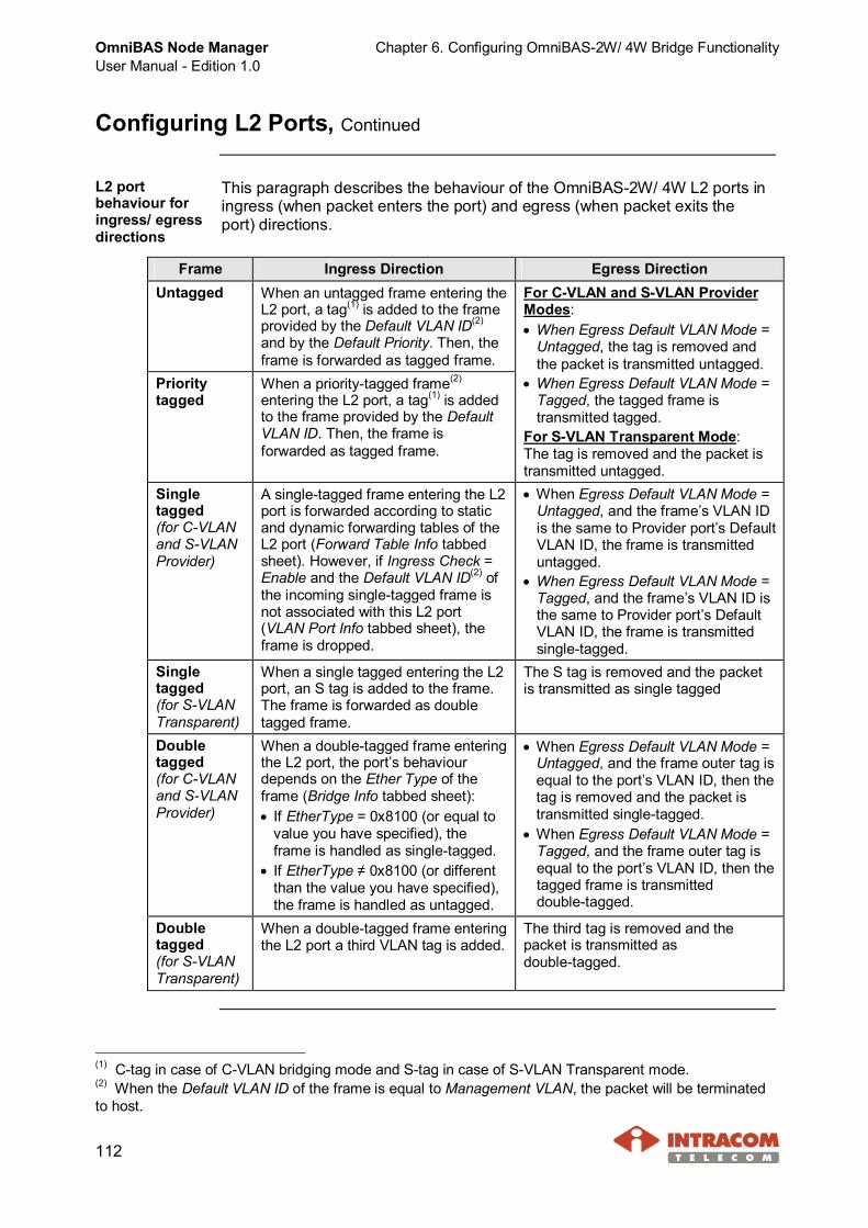
OmniBAS Node ManagerUser Manual - Edition 1.0
Chapter 6. Configuring OmniBAS-2W/ 4W Bridge Functionality
112
Configuring L2 Ports, Continued
L2 portbehaviour foringress/ egressdirections
This paragraph describes the behaviour of the OmniBAS-2W/ 4W L2 ports iningress (when packet enters the port) and egress (when packet exits theport) directions.
Frame Ingress Direction Egress DirectionUntagged When an untagged frame entering the
L2 port, a tag(1) is added to the frameprovided by the Default VLAN ID(2)
and by the Default Priority. Then, theframe is forwarded as tagged frame.
Prioritytagged
When a priority-tagged frame(2)
entering the L2 port, a tag(1) is addedto the frame provided by the DefaultVLAN ID. Then, the frame isforwarded as tagged frame.
For C-VLAN and S-VLAN ProviderModes:· When Egress Default VLAN Mode =
Untagged, the tag is removed andthe packet is transmitted untagged.
· When Egress Default VLAN Mode =Tagged, the tagged frame istransmitted tagged.
For S-VLAN Transparent Mode:The tag is removed and the packet istransmitted untagged.
Singletagged(for C-VLANand S-VLANProvider)
A single-tagged frame entering the L2port is forwarded according to staticand dynamic forwarding tables of theL2 port (Forward Table Info tabbedsheet). However, if Ingress Check =Enable and the Default VLAN ID(2) ofthe incoming single-tagged frame isnot associated with this L2 port(VLAN Port Info tabbed sheet), theframe is dropped.
· When Egress Default VLAN Mode =Untagged, and the frame’s VLAN IDis the same to Provider port’s DefaultVLAN ID, the frame is transmitteduntagged.
· When Egress Default VLAN Mode =Tagged, and the frame’s VLAN ID isthe same to Provider port’s DefaultVLAN ID, the frame is transmittedsingle-tagged.
Singletagged(for S-VLANTransparent)
When a single tagged entering the L2port, an S tag is added to the frame.The frame is forwarded as doubletagged frame.
The S tag is removed and the packetis transmitted as single tagged
Doubletagged(for C-VLANand S-VLANProvider)
When a double-tagged frame enteringthe L2 port, the port’s behaviourdepends on the Ether Type of theframe (Bridge Info tabbed sheet):· If EtherType = 0x8100 (or equal to
value you have specified), theframe is handled as single-tagged.
· If EtherType ≠ 0x8100 (or differentthan the value you have specified),the frame is handled as untagged.
· When Egress Default VLAN Mode =Untagged, and the frame outer tag isequal to the port’s VLAN ID, then thetag is removed and the packet istransmitted single-tagged.
· When Egress Default VLAN Mode =Tagged, and the frame outer tag isequal to the port’s VLAN ID, then thetagged frame is transmitteddouble-tagged.
Doubletagged(for S-VLANTransparent)
When a double-tagged frame enteringthe L2 port a third VLAN tag is added.
The third tag is removed and thepacket is transmitted asdouble-tagged.
(1) C-tag in case of C-VLAN bridging mode and S-tag in case of S-VLAN Transparent mode.(2) When the Default VLAN ID of the frame is equal to Management VLAN, the packet will be terminatedto host.

Chapter 6. Configuring OmniBAS-2W/ 4W Bridge Functionality OmniBAS Node ManagerUser Manual - Edition 1.0
113
Configuring Ethernet QoS
Introduction OmniBAS-2W/ 4W system supports advanced Ethernet QoS functionality atLayer 2/ 3 of OSI model enabling the traffic prioritization and performingdynamic multicast filtering. Ethernet QoS prioritizes network traffic andmanages available bandwidth so that the most important traffic (packets withhigher priority) to be forwarded first when network congestion occurs.This paragraph describes how to assign:· Priority Mapping (IEEE 802.1 P/Q priority) in a VLAN packet (Layer 2).- OmniBAS-2W system supports eight CoS queues, where 0 is the highest
traffic queue priority and 7 is the lowest traffic queue priority.- OmniBAS-4W system supports four CoS queues to the modem
(wireless) ports (where 0 is the highest traffic queue priority and 3 is thelowest traffic queue priority) and eight CoS queues to the GbE ports(where 0 is the highest traffic queue priority and 7 is the lowest trafficqueue priority).
· DSCP (Differentiated Services Code Point) in an IP packet (Layer 3) (i.e.how to assign DSCP values to specific CoS queues).
NOTE Screens of an OmniBAS-2W ME are mainly used for describingthe procedures of this paragraph, but the procedures are exactlythe same for the OmniBAS-4W MEs.
Continued on next page
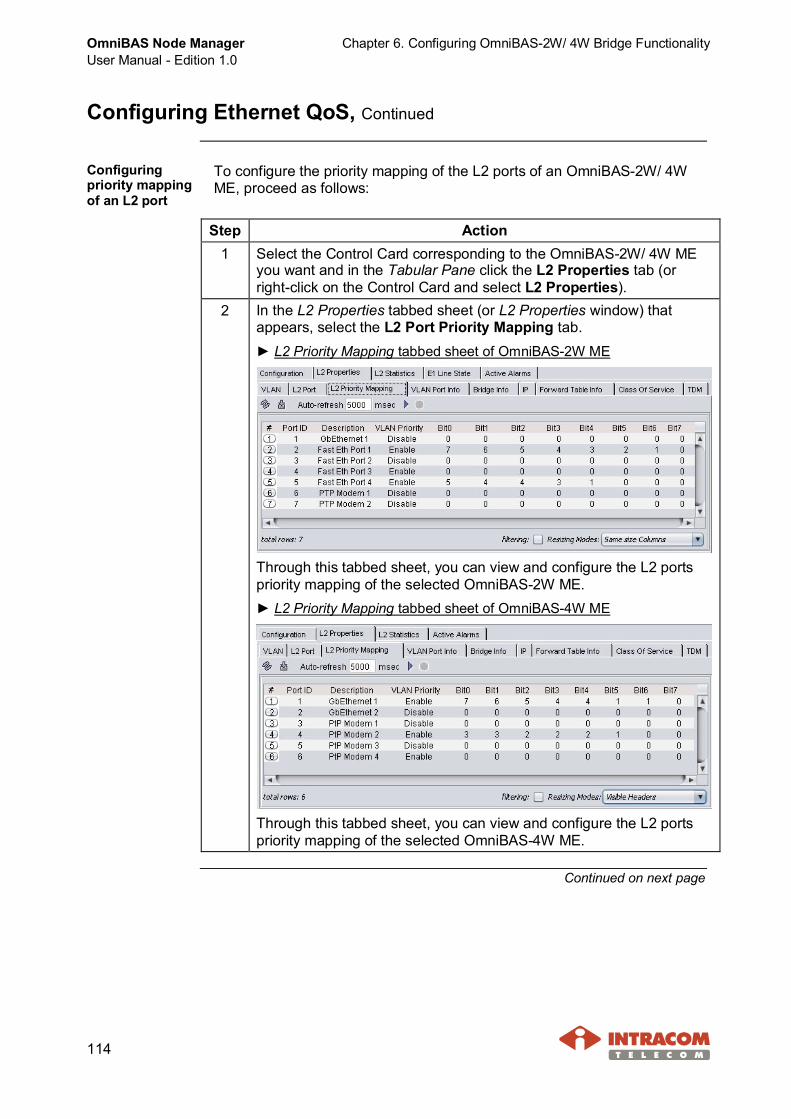
OmniBAS Node ManagerUser Manual - Edition 1.0
Chapter 6. Configuring OmniBAS-2W/ 4W Bridge Functionality
114
Configuring Ethernet QoS, Continued
Configuringpriority mappingof an L2 port
To configure the priority mapping of the L2 ports of an OmniBAS-2W/ 4WME, proceed as follows:
Step Action1 Select the Control Card corresponding to the OmniBAS-2W/ 4W ME
you want and in the Tabular Pane click the L2 Properties tab (orright-click on the Control Card and select L2 Properties).
2 In the L2 Properties tabbed sheet (or L2 Properties window) thatappears, select the L2 Port Priority Mapping tab.► L2 Priority Mapping tabbed sheet of OmniBAS-2W ME
Through this tabbed sheet, you can view and configure the L2 portspriority mapping of the selected OmniBAS-2W ME.► L2 Priority Mapping tabbed sheet of OmniBAS-4W ME
Through this tabbed sheet, you can view and configure the L2 portspriority mapping of the selected OmniBAS-4W ME.
Continued on next page

Chapter 6. Configuring OmniBAS-2W/ 4W Bridge Functionality OmniBAS Node ManagerUser Manual - Edition 1.0
115
Configuring Ethernet QoS, Continued
Configuring priority mapping of an L2 port (continued)
Step Action3 To configure the priority mapping of an L2 port, select the port (e.g.
OmniBAS-2W Fast Eth Port 2). The editable fields turn into orange.
4 Double click the VLAN Priority drop-down list and select:· Enable - The VLAN priority of the packets entering L2 port can be
mapped to one of the eight (or four) CoS queues supported by theOmniBAS-2W/ 4W system. The packets with the highest priorityqueue are always transmitted first and packets with lowest priorityqueue are always transmitted last.
· Disable - When the priority mapping of the L2 port is not enabled, allpackets are forwarded from the L2 port.
If you select Disable, proceed to step 6.
Continued on next page

OmniBAS Node ManagerUser Manual - Edition 1.0
Chapter 6. Configuring OmniBAS-2W/ 4W Bridge Functionality
116
Configuring Ethernet QoS, Continued
Configuring priority mapping of an L2 port (continued)
Step Action5 Assign a CoS queue to each incoming VLAN priority(1) (Bit 0 to Bit 7) of the
selected L2 port by using the corresponding drop-down lists.
►L2 Port PriorityMapping tabbedsheet ofOmniBAS-2W ME
►L2 Port PriorityMapping tabbedsheet ofOmniBAS-4W ME
About Set all Bits functionIn case you want toassign the same CoSqueue to allincoming-VLANpriorities(1), right-click onthe L2 port and from thedrop-down select the CoSqueue you want (e.g. Setall Bits to 0).
In this way, when a CoS queue is assigned more times than the others, you canavoid assigning the CoS queues one-by-one (i.e. you assign the CoS queue youwant to all incoming-VLAN priorities(1), and then you select the different ones,wherever needed).
6 When you complete, click the button to apply the priority mappingassignments.
End of procedure.
Continued on next page
(1) Default Priority field of Ethernet frame (see Appendix - IEEE 802.1q / ad Ethernet Frames).

Chapter 6. Configuring OmniBAS-2W/ 4W Bridge Functionality OmniBAS Node ManagerUser Manual - Edition 1.0
117
Configuring Ethernet QoS, Continued
ConfiguringDSCP prioritiesof an L2 port
To assign DSCP entries(1) to an OmniBAS-2W/ 4W L2 port and associatethem with CoS queues, proceed as follows.
NOTE Screens of an OmniBAS-2W ME are mainly used for describingthe following procedure, but the procedure is exactly the same forthe OmniBAS-4W MEs.
Step Action1 Configure the priority-to-queue mapping of the L2 port, as described
in the previous par. Configuring priority mapping of an L2 port. Then,perform the following steps.
2 In the L2 Properties tabbed sheet, select the L2 Port tab.
3 Right-click on the L2 port you want (e.g. OmniBAS-2W Fast Eth Port2), and from the drop-down list, select DSCP Remarking to P bit.
Continued on next page
(1) The DSCP entry is written to the TOS/DSCP field in the IP header of the incoming packets and takesvalues from 0 for low priority to 63 for high priority.

OmniBAS Node ManagerUser Manual - Edition 1.0
Chapter 6. Configuring OmniBAS-2W/ 4W Bridge Functionality
118
Configuring Ethernet QoS, Continued
Configuring DSCP priorities of an L2 port (continued)
Step Action4 The DSCP Remarking to P
bit window that appears,displays the DSCPpriorities (0 to 63) assignedto P bits (0 to 7).Actually, the P bitcorresponds to the CoSqueue that is mapped tothe VLAN priority of theincoming packet.
The following table shows an example of DSCP remarking to P bit:DSCP
priorities 0 8 16 24 32 40 48 56
P bit 0 1 2 3 4 5 6 7
5 To specify a DSCP entry to aP bit for the selected L2 port,right-click on the DSCP listand from the drop-down menu,select Add(1).
6 A new row is created at theend of the list.
Continued on next page
(1) If you select an existing DSCP entry and then you right-click, the drop-down menu that appearsincludes also the Remove option.

Chapter 6. Configuring OmniBAS-2W/ 4W Bridge Functionality OmniBAS Node ManagerUser Manual - Edition 1.0
119
Configuring Ethernet QoS, Continued
Configuring DSCP priorities of an L2 port (continued)
Step Action7 Double click on the DSCP
field and from thedrop-down list, select theDSCP priority (from 0 to 63)you want (e.g. 43).
8 Double click on the P bitfield and from thedrop-down list, select the Pbit value (from 0 to 7) toassociate with the selectedDSCP priority(e.g. 2).
9 Click the button.
Continued on next page
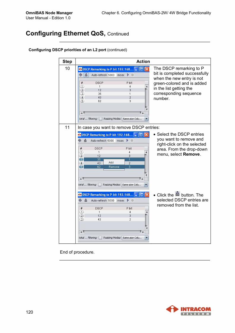
OmniBAS Node ManagerUser Manual - Edition 1.0
Chapter 6. Configuring OmniBAS-2W/ 4W Bridge Functionality
120
Configuring Ethernet QoS, Continued
Configuring DSCP priorities of an L2 port (continued)
Step Action10 The DSCP remarking to P
bit is completed successfullywhen the new entry is notgreen-colored and is addedin the list getting thecorresponding sequencenumber.
11 In case you want to remove DSCP entries:· Select the DSCP entries
you want to remove andright-click on the selectedarea. From the drop-downmenu, select Remove.
· Click the button. Theselected DSCP entries areremoved from the list.
End of procedure.
Chapter 6. Configuring OmniBAS-2W/ 4W Bridge Functionality OmniBAS Node ManagerUser Manual - Edition 1.0
121
Configuring Policer Parameters
Introduction This paragraph describes how to create Two-Rate TCM (Three Color Marking)policers in an OmniBAS-2W/ 4W ME, how to modify the parameters of aTwo-Rate TCM policer or how to remove it.Also, this paragraph provides a short description about policing mechanism,bandwidth profile parameters and policer types supported by OmniBAS-2W/ 4Wsystem.
AboutPolicingMechanism
Two-Rate TCM policer requires a bandwidth profile that specifies the averagerate of “committed” and “excess” Ethernet packets allowed into network at theswitch port.· Packets that are transmitted up to the “committed” rate are allowed into the
provider’s network and delivered per the service performance objectivesspecified in the Service Level Agreement (SLA) or Service Level Specification(SLS). These packets are “in-profile” or “conformant” with the bandwidthprofile.
· Packets sent above the “committed” rate and below the “excess” rate areallowed into the provider’s network but are delivered without any serviceperformance objectives. These packets are “out-of-profile” or “non-conformant” to the bandwidth profile.
· Packets sent above the “excess” rate are discarded.OmniBAS-2W/4W supports the Two-Rate three colors method(1) of measuringthe bandwidth profile. Two-rate, three-color metering allows incoming framesthat conform to the CIR to be admitted to the network. Frames that exceed eventhe EIR are discarded immediately, and frames that exceed the CIR, but not theEIR, are marked yellow for possible discard later, should the network becomecongested.
Continued on next page
(1) There are two main methods of measuring the bandwidth profile, the Two-Rate, three colors meteringand the Single-Rate, three colors metering. OmniBAS-2W/ 4W system supports the Two-Rate, threecolors metering method.
OmniBAS Node ManagerUser Manual - Edition 1.0
Chapter 6. Configuring OmniBAS-2W/ 4W Bridge Functionality
122
Configuring Policer Parameters, Continued
BandwidthProfileParameters
· The Committed Information Rate (CIR) is the average rate up to whichpackets are marked green. These packets are referred to as CIR-conformant.
· The Excess Information Rate (EIR) specifies the average rate up to whichpackets are admitted to the network. The EIR is greater than or equal to theCIR. Packets that exceed the CIR, but are below the EIR are marked yellow.Because these packets do not conform to the CIR, the network does notprovide any guarantees with regard to their delivery.Packets that exceed the EIR, do not conform and are marked red, and arediscarded. Because traffic levels can fluctuate, the two rate, three colormetering process enables the traffic to burst above the CIR and EIR a certainamount before marking the packets yellow and red, respectively.
· The Committed Burst Size (CBS) is the maximum number of bytes allowedfor incoming packets to burst above the CIR, but still be marked green.
· The Excess Burst Size (EBS) is the maximum number of bytes allowed forincoming packets to burst above the EIR and still be marked yellow. Whenthe burst size has been exceeded, packets above the EIR are marked red.
Policer types · Color Blind TCM Policer: directs all frames through the entire policer,regardless of their color, thus enables the frame to receive any outputcolor no matter what color it entered with. This means that a low priorityframe (red) can receive a higher priority (e.g. green).
· Color Aware TCM Policer: classifies the frame’s color before it is sentthrough the policer, and thus enables a frame to receive only the same ora lower priority than the one it has. For example: a yellow marked framecannot receive a green color in a color aware TCM policer, only a yellow ora red color.
Continued on next page
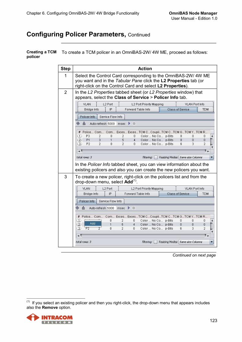
Chapter 6. Configuring OmniBAS-2W/ 4W Bridge Functionality OmniBAS Node ManagerUser Manual - Edition 1.0
123
Configuring Policer Parameters, Continued
Creating a TCMpolicer
To create a TCM policer in an OmniBAS-2W/ 4W ME, proceed as follows:
Step Action1 Select the Control Card corresponding to the OmniBAS-2W/ 4W ME
you want and in the Tabular Pane click the L2 Properties tab (orright-click on the Control Card and select L2 Properties).
2 In the L2 Properties tabbed sheet (or L2 Properties window) thatappears, select the Class of Service > Policer Info tab.
In the Policer Info tabbed sheet, you can view information about theexisting policers and also you can create the new policers you want.
3 To create a new policer, right-click on the policers list and from thedrop-down menu, select Add(1).
Continued on next page
(1) If you select an existing policer and then you right-click, the drop-down menu that appears includesalso the Remove option.

OmniBAS Node ManagerUser Manual - Edition 1.0
Chapter 6. Configuring OmniBAS-2W/ 4W Bridge Functionality
124
Configuring Policer Parameters, Continued
Creating a TCM policer (continued)
Step Action4 The Policer Creation window
appears.
5 In the Policer Name text box, type the name of the policer.6 From the Coupling Flag drop-down list, select one of the following
values. The Coupling Flag value has the effect of controlling thevolume of the Service Frames that are declared Yellow.· No Coupling - The long term average bit rate of Service Frames that
are declared Yellow is bounded by EIR.· Coupling - The long term average bit rate of Service Frames that are
declared Yellow is bounded by CIR + EIR depending on volume ofthe offered Service Frames that are declared Green.
In both cases the burst size of the Service Frames that are declaredYellow is bounded by EBS.
7 From the TCM Color Mode drop-down list, select:· Color Aware: The frame’s input color (e.g. priority) is considered by
the policer and can only be increased(1).· Color Blind: The frame’s input color (e.g. priority) is ignored by the
policer(2). The policer only measures the traffic parameters (i.e. CIR/CBS and EIR/ EBS).
Continued on next page
(1) TCM policer classifies the frame’s input color and thus enables a frame to receive only the same or alower priority than the one it has. For example, a yellow marked frame cannot receive a green color, onlya yellow or red.(2) All frames are directed inside the policer regardless of their input color enabling the frame to receiveany output color. This means that a low priority frame (red) can receive a higher priority (e.g. green).

Chapter 6. Configuring OmniBAS-2W/ 4W Bridge Functionality OmniBAS Node ManagerUser Manual - Edition 1.0
125
Configuring Policer Parameters, Continued
Creating a TCM policer (continued)
Step Action8 Enter a value for the bandwidth profile parameters in the
corresponding text boxes:· Committed Information Rate (CIR) - Average rate (in kbps) up to
which the frames are delivered per service performance objectives.Frames complies CIR can be also referred as CIR-conformant. CIRis an average rate because all frames are always sent at the UNIspeed.
· Committed Burst Size (CBS) - Maximum number of bytes allowedfor incoming frames to still be CIR-conformant. CBS value dependson the service type that the created policer is targeting to support.
· Excess Information Rate (EIR) - Average rate up to which excessframes (frames whose average rate > CIR) are admitted intonetwork. These frames are not CIR-conformant and are hencedelivered without any performance objectives. The EIR is anaverage rate because all frames are always sent at the UNI speed.EIR value should be less than or equal to the UNI speed.
· Excess Burst Size (EBS) - Maximum number of bytes allowed forincoming frames to still be EIR-conformant.
9 From the TCM CoS Type drop-down list, you can specify the frame’sinput color (priority):· p-bits: The frame’s input color (priority) is determined by VLAN
priority bits within the Ethernet header.· DSCP: The frame’s input color (priority) is determined by DSCP field
within the IP header.
NOTE The TCM CoS Type attribute should be specified only for aColor Aware policer.
Continued on next page
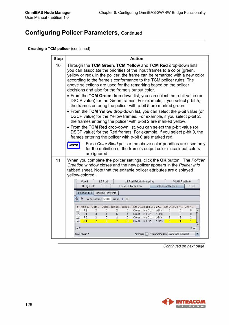
OmniBAS Node ManagerUser Manual - Edition 1.0
Chapter 6. Configuring OmniBAS-2W/ 4W Bridge Functionality
126
Configuring Policer Parameters, Continued
Creating a TCM policer (continued)
Step Action10 Through the TCM Green, TCM Yellow and TCM Red drop-down lists,
you can associate the priorities of the input frames to a color (green,yellow or red). In the policer, the frame can be remarked with a new coloraccording to the frame’s conformance to the TCM policer rules. Theabove selections are used for the remarking based on the policerdecisions and also for the frame’s output color.· From the TCM Green drop-down list, you can select the p-bit value (or
DSCP value) for the Green frames. For example, if you select p-bit 5,the frames entering the policer with p-bit 5 are marked green.
· From the TCM Yellow drop-down list, you can select the p-bit value (orDSCP value) for the Yellow frames. For example, if you select p-bit 2,the frames entering the policer with p-bit 2 are marked yellow.
· From the TCM Red drop-down list, you can select the p-bit value (orDSCP value) for the Red frames. For example, if you select p-bit 0, theframes entering the policer with p-bit 0 are marked red.
NOTE For a Color Blind policer the above color-priorities are used onlyfor the definition of the frame’s output color since input colorsare ignored.
11 When you complete the policer settings, click the OK button. The PolicerCreation window closes and the new policer appears in the Policer Infotabbed sheet. Note that the editable policer attributes are displayedyellow-colored.
Continued on next page
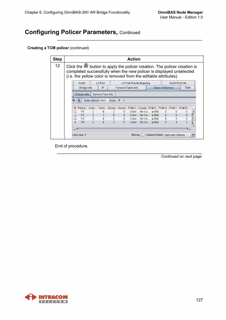
Chapter 6. Configuring OmniBAS-2W/ 4W Bridge Functionality OmniBAS Node ManagerUser Manual - Edition 1.0
127
Configuring Policer Parameters, Continued
Creating a TCM policer (continued)
Step Action12 Click the button to apply the policer creation. The policer creation is
completed successfully when the new policer is displayed unselected(i.e. the yellow color is removed from the editable attributes).
End of procedure.
Continued on next page

OmniBAS Node ManagerUser Manual - Edition 1.0
Chapter 6. Configuring OmniBAS-2W/ 4W Bridge Functionality
128
Configuring Policer Parameters, Continued
Modifying orRemovingpolicers
To modify or remove a TCM policer, proceed as follows:
Step Action1 Select the Control Card corresponding to the OmniBAS-2W/ 4W ME
you want and in the Tabular Pane click the L2 Properties tab (orright-click on the Control Card and select L2 Properties).
2 In the L2 Properties tabbed sheet (or L2 Properties window) thatappears, select the Class of Service > Policer Info tab.
In the Policer Info tabbed sheet, you can view information about theexisting policers.
3 To modify theattributes of apolicer:· Select the policer
you want. Theattributes that canbe changedbecomeyellow-colored.
· To change anattribute,double-click on it.Type or select thenew value youwant and pressENTER.
· Repeat for all attributes you want to change.
· When you complete the changes on the policer, click the button.
Continued on next page

Chapter 6. Configuring OmniBAS-2W/ 4W Bridge Functionality OmniBAS Node ManagerUser Manual - Edition 1.0
129
Configuring Policer Parameters, Continued
Modifying or Removing policers (continued)
Step Action4 · To remove
policers from theOmniBAS-2W/4W ME, selectthe policers andright-click on theselected area.From thedrop-down menu,select Remove.
· Click thebutton. Theselected policersare removed fromthe policers list.
End of procedure.
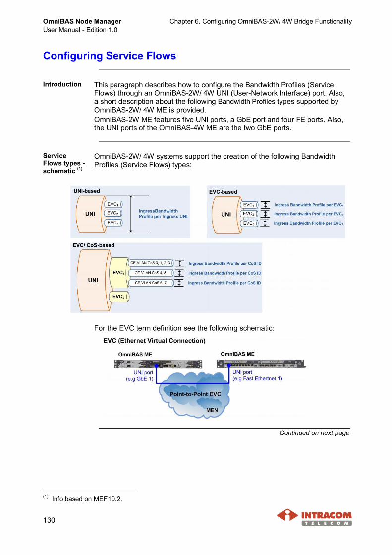
OmniBAS Node ManagerUser Manual - Edition 1.0
Chapter 6. Configuring OmniBAS-2W/ 4W Bridge Functionality
130
Configuring Service Flows
Introduction This paragraph describes how to configure the Bandwidth Profiles (ServiceFlows) through an OmniBAS-2W/ 4W UNI (User-Network Interface) port. Also,a short description about the following Bandwidth Profiles types supported byOmniBAS-2W/ 4W ME is provided.OmniBAS-2W ME features five UNI ports, a GbE port and four FE ports. Also,the UNI ports of the OmniBAS-4W ME are the two GbE ports.
ServiceFlows types -schematic (1)
OmniBAS-2W/ 4W systems support the creation of the following BandwidthProfiles (Service Flows) types:
For the EVC term definition see the following schematic:
Continued on next page
(1) Info based on MEF10.2.
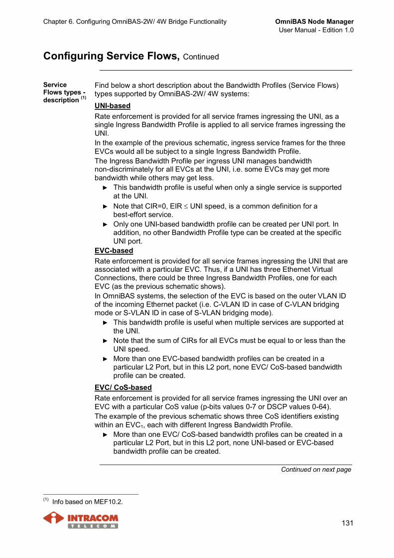
Chapter 6. Configuring OmniBAS-2W/ 4W Bridge Functionality OmniBAS Node ManagerUser Manual - Edition 1.0
131
Configuring Service Flows, Continued
ServiceFlows types -description (1)
Find below a short description about the Bandwidth Profiles (Service Flows)types supported by OmniBAS-2W/ 4W systems:UNI-basedRate enforcement is provided for all service frames ingressing the UNI, as asingle Ingress Bandwidth Profile is applied to all service frames ingressing theUNI.In the example of the previous schematic, ingress service frames for the threeEVCs would all be subject to a single Ingress Bandwidth Profile.The Ingress Bandwidth Profile per ingress UNI manages bandwidthnon-discriminately for all EVCs at the UNI, i.e. some EVCs may get morebandwidth while others may get less.
► This bandwidth profile is useful when only a single service is supportedat the UNI.
► Note that CIR=0, EIR £ UNI speed, is a common definition for abest-effort service.
► Only one UNI-based bandwidth profile can be created per UNI port. Inaddition, no other Bandwidth Profile type can be created at the specificUNI port.
EVC-basedRate enforcement is provided for all service frames ingressing the UNI that areassociated with a particular EVC. Thus, if a UNI has three Ethernet VirtualConnections, there could be three Ingress Bandwidth Profiles, one for eachEVC (as the previous schematic shows).In OmniBAS systems, the selection of the EVC is based on the outer VLAN IDof the incoming Ethernet packet (i.e. C-VLAN ID in case of C-VLAN bridgingmode or S-VLAN ID in case of S-VLAN bridging mode).
► This bandwidth profile is useful when multiple services are supported atthe UNI.
► Note that the sum of CIRs for all EVCs must be equal to or less than theUNI speed.
► More than one EVC-based bandwidth profiles can be created in aparticular L2 Port, but in this L2 port, none EVC/ CoS-based bandwidthprofile can be created.
EVC/ CoS-basedRate enforcement is provided for all service frames ingressing the UNI over anEVC with a particular CoS value (p-bits values 0-7 or DSCP values 0-64).The example of the previous schematic shows three CoS identifiers existingwithin an EVC1, each with different Ingress Bandwidth Profile.
► More than one EVC/ CoS-based bandwidth profiles can be created in aparticular L2 Port, but in this L2 port, none UNI-based or EVC-basedbandwidth profile can be created.
Continued on next page
(1) Info based on MEF10.2.
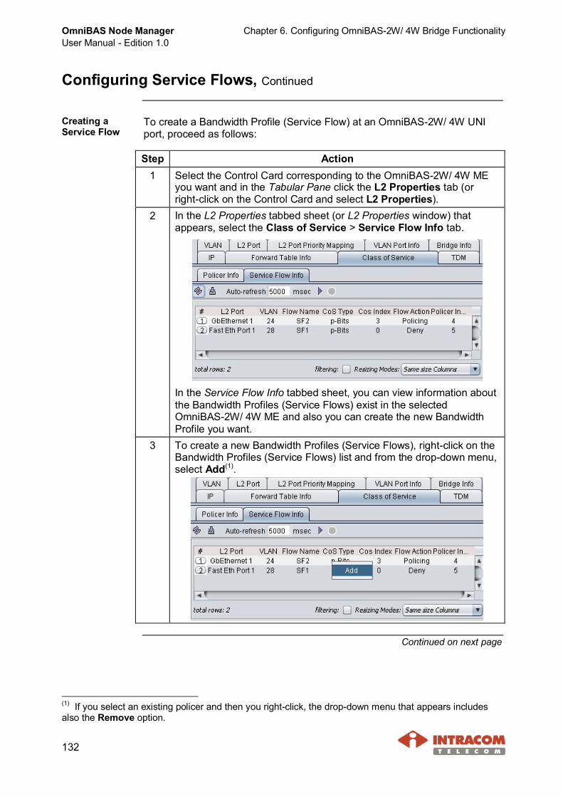
OmniBAS Node ManagerUser Manual - Edition 1.0
Chapter 6. Configuring OmniBAS-2W/ 4W Bridge Functionality
132
Configuring Service Flows, Continued
Creating aService Flow
To create a Bandwidth Profile (Service Flow) at an OmniBAS-2W/ 4W UNIport, proceed as follows:
Step Action1 Select the Control Card corresponding to the OmniBAS-2W/ 4W ME
you want and in the Tabular Pane click the L2 Properties tab (orright-click on the Control Card and select L2 Properties).
2 In the L2 Properties tabbed sheet (or L2 Properties window) thatappears, select the Class of Service > Service Flow Info tab.
In the Service Flow Info tabbed sheet, you can view information aboutthe Bandwidth Profiles (Service Flows) exist in the selectedOmniBAS-2W/ 4W ME and also you can create the new BandwidthProfile you want.
3 To create a new Bandwidth Profiles (Service Flows), right-click on theBandwidth Profiles (Service Flows) list and from the drop-down menu,select Add(1).
Continued on next page
(1) If you select an existing policer and then you right-click, the drop-down menu that appears includesalso the Remove option.
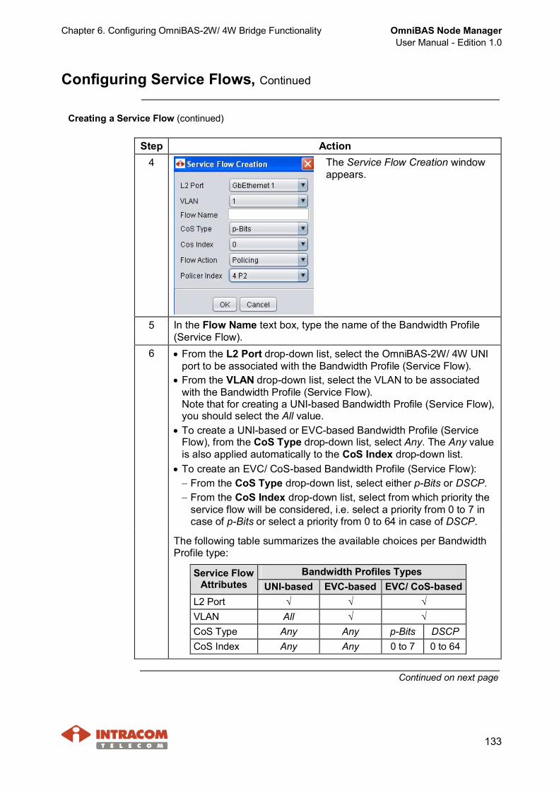
Chapter 6. Configuring OmniBAS-2W/ 4W Bridge Functionality OmniBAS Node ManagerUser Manual - Edition 1.0
133
Configuring Service Flows, Continued
Creating a Service Flow (continued)
Step Action4 The Service Flow Creation window
appears.
5 In the Flow Name text box, type the name of the Bandwidth Profile(Service Flow).
6 · From the L2 Port drop-down list, select the OmniBAS-2W/ 4W UNIport to be associated with the Bandwidth Profile (Service Flow).
· From the VLAN drop-down list, select the VLAN to be associatedwith the Bandwidth Profile (Service Flow).Note that for creating a UNI-based Bandwidth Profile (Service Flow),you should select the All value.
· To create a UNI-based or EVC-based Bandwidth Profile (ServiceFlow), from the CoS Type drop-down list, select Any. The Any valueis also applied automatically to the CoS Index drop-down list.
· To create an EVC/ CoS-based Bandwidth Profile (Service Flow):- From the CoS Type drop-down list, select either p-Bits or DSCP.- From the CoS Index drop-down list, select from which priority the
service flow will be considered, i.e. select a priority from 0 to 7 incase of p-Bits or select a priority from 0 to 64 in case of DSCP.
The following table summarizes the available choices per BandwidthProfile type:
Bandwidth Profiles TypesService FlowAttributes UNI-based EVC-based EVC/ CoS-based
L2 Port √ √ √VLAN All √ √CoS Type Any Any p-Bits DSCPCoS Index Any Any 0 to 7 0 to 64
Continued on next page

OmniBAS Node ManagerUser Manual - Edition 1.0
Chapter 6. Configuring OmniBAS-2W/ 4W Bridge Functionality
134
Configuring Service Flows, Continued
Creating a Service Flow (continued)
Step Action7 From the Policer Index drop-down list, select the policer to be applied
on the Bandwidth Profile (Service Flow).
NOTE You can set the same policer for different Bandwidth Profiles(Service Flows).
8 From the Flow Action drop-down list, select the action to be appliedto the Ethernet packets of the specific Bandwidth Profile (ServiceFlow):· Deny: The Ethernet packets are dropped.· Policing: The Ethernet packets are treated by the Policer according
to the specific Bandwidth Profile (Service Flow).9 When you complete the Bandwidth Profile (Service Flow) settings,
click the OK button. The Service Flow Creation window closes and thenew Bandwidth Profile (Service Flow) appears in the Service Flow Infotabbed sheet. Note that the editable service flow attributes aredisplayed yellow-colored.
Continued on next page
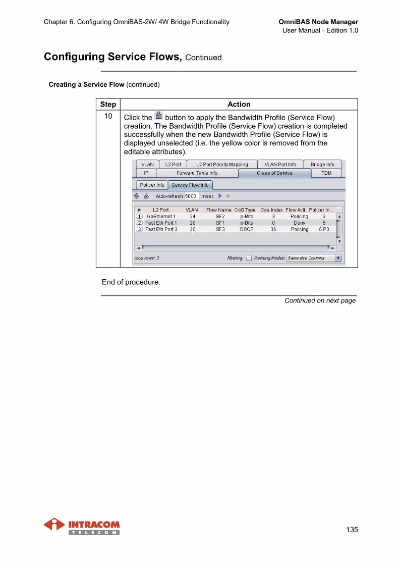
Chapter 6. Configuring OmniBAS-2W/ 4W Bridge Functionality OmniBAS Node ManagerUser Manual - Edition 1.0
135
Configuring Service Flows, Continued
Creating a Service Flow (continued)
Step Action10 Click the button to apply the Bandwidth Profile (Service Flow)
creation. The Bandwidth Profile (Service Flow) creation is completedsuccessfully when the new Bandwidth Profile (Service Flow) isdisplayed unselected (i.e. the yellow color is removed from theeditable attributes).
End of procedure.
Continued on next page

OmniBAS Node ManagerUser Manual - Edition 1.0
Chapter 6. Configuring OmniBAS-2W/ 4W Bridge Functionality
136
Configuring Service Flows, Continued
Modifying orremovingservice flows
To modify or remove a Bandwidth Profile (Service Flow), proceed as follows:
Step Action1 Select the Control Card corresponding to the OmniBAS-2W/ 4W ME you
want and in the Tabular Pane click the L2 Properties tab (or right-clickon the Control Card and select L2 Properties).
2 In the L2 Properties tabbed sheet (or L2 Properties window) thatappears, select the Class of Service > Service Flow Info tab.
In the Service Flow Info tabbed sheet, you can view information aboutthe existing Bandwidth Profiles (Service Flows).
3 To modify theattributes of aBandwidth Profile(Service Flow):· Select the service
flow you want. Theattributes that canbe changed becomeyellow-colored.
· To change anattribute,double-click on it.Type or select thenew value you wantand press ENTER.
· Repeat for all attributes you want to change.
· When you complete the changes on the service flow, click thebutton.
Continued on next page
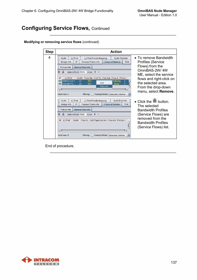
Chapter 6. Configuring OmniBAS-2W/ 4W Bridge Functionality OmniBAS Node ManagerUser Manual - Edition 1.0
137
Configuring Service Flows, Continued
Modifying or removing service flows (continued)
Step Action4 · To remove Bandwidth
Profiles (ServiceFlows) from theOmniBAS-2W/ 4WME, select the serviceflows and right-click onthe selected area.From the drop-downmenu, select Remove.
· Click the button.The selectedBandwidth Profiles(Service Flows) areremoved from theBandwidth Profiles(Service Flows) list.
End of procedure.

OmniBAS Node ManagerUser Manual - Edition 1.0
Chapter 6. Configuring OmniBAS-2W/ 4W Bridge Functionality
138
Configuring Forwarding Process
Introduction This paragraph describes how to:· View the static and dynamic forwarding entries of an OmniBAS-2W/ 4W ME.· Add (or remove) static forwarding entries in an OmniBAS-2W/ 4W ME.The static and dynamic forwarding tables specify the MAC addresses that areforwarded at specific L2 ports avoiding flooding on the OmniBAS-2W/ 4Wbridge.Static entries do not expire and cannot be changed except by managementcontrol (i.e. the uni|MS operator). Dynamic entries are those that are createdby the learning process. The existence of the dynamic entries in the DynamicForwarding Table depends on the Aging Timeout(1) defined for the specificOmniBAS-2W/ 4W ME (through the Bridge Info tabbed sheet).
NOTE Screens of an OmniBAS-2W ME are mainly used for describing theprocedures of this paragraph, but the procedures are exactly thesame for the OmniBAS-4W MEs.
Continued on next page
(1) About Aging Timeout: When a MAC address entry is created in the Dynamic Forwarding Table for anL2 port, an idle timer is started for that entry. Every time a new frame with this MAC address is receivedfrom the L2 port, the idle timer is reset to zero. Once the timer reaches the Aging Timeout (no packetfrom this MAC address for that time), the MAC address entry for this L2 port is removed from theDynamic Forwarding Table.
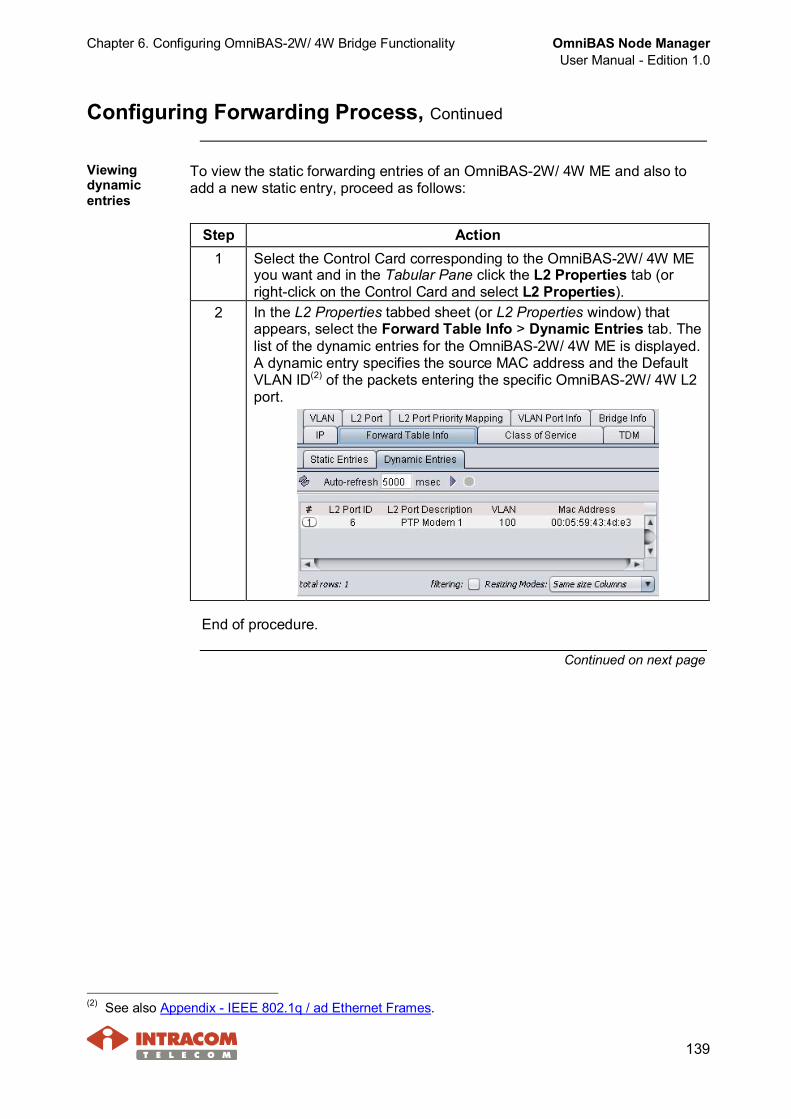
Chapter 6. Configuring OmniBAS-2W/ 4W Bridge Functionality OmniBAS Node ManagerUser Manual - Edition 1.0
139
Configuring Forwarding Process, Continued
Viewingdynamicentries
To view the static forwarding entries of an OmniBAS-2W/ 4W ME and also toadd a new static entry, proceed as follows:
Step Action1 Select the Control Card corresponding to the OmniBAS-2W/ 4W ME
you want and in the Tabular Pane click the L2 Properties tab (orright-click on the Control Card and select L2 Properties).
2 In the L2 Properties tabbed sheet (or L2 Properties window) thatappears, select the Forward Table Info > Dynamic Entries tab. Thelist of the dynamic entries for the OmniBAS-2W/ 4W ME is displayed.A dynamic entry specifies the source MAC address and the DefaultVLAN ID(2) of the packets entering the specific OmniBAS-2W/ 4W L2port.
End of procedure.
Continued on next page
(2) See also Appendix - IEEE 802.1q / ad Ethernet Frames.
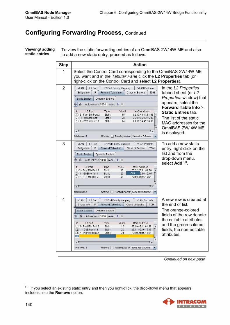
OmniBAS Node ManagerUser Manual - Edition 1.0
Chapter 6. Configuring OmniBAS-2W/ 4W Bridge Functionality
140
Configuring Forwarding Process, Continued
Viewing/ addingstatic entries
To view the static forwarding entries of an OmniBAS-2W/ 4W ME and alsoto add a new static entry, proceed as follows:
Step Action1 Select the Control Card corresponding to the OmniBAS-2W/ 4W ME
you want and in the Tabular Pane click the L2 Properties tab (orright-click on the Control Card and select L2 Properties).
2 In the L2 Propertiestabbed sheet (or L2Properties window) thatappears, select theForward Table Info >Static Entries tab.The list of the staticMAC addresses for theOmniBAS-2W/ 4W MEis displayed.
3 To add a new staticentry, right-click on thelist and from thedrop-down menu,select Add (1).
4 A new row is created atthe end of list.The orange-coloredfields of the row denotethe editable attributesand the green-coloredfields, the non-editableattributes.
Continued on next page
(1) If you select an existing static entry and then you right-click, the drop-down menu that appearsincludes also the Remove option.

Chapter 6. Configuring OmniBAS-2W/ 4W Bridge Functionality OmniBAS Node ManagerUser Manual - Edition 1.0
141
Configuring Forwarding Process, Continued
Viewing/ adding static entries (continued)
Step Action5 Double click on the L2
Port field and from thedrop-down list, selectthe L2 port you want(e.g. 2-Fast Eth Port 1of OmniBAS-2W).
6 In the same way:· Double click on the VLAN field and from the drop-down list, selectthe VLAN you want (e.g. 22).· Double click on the MAC Address field and type the source MACaddress to which the filtering to be applied (e.g. 12:15:18:62:34:22)
7 Press ENTER (or clickon an existing staticentry) and click thebutton.
8 The addition of the newstatic entry iscompletedsuccessfully, when thenew entry is added inthe list getting thecorrespondingsequence number.
End of procedure.
Continued on next page
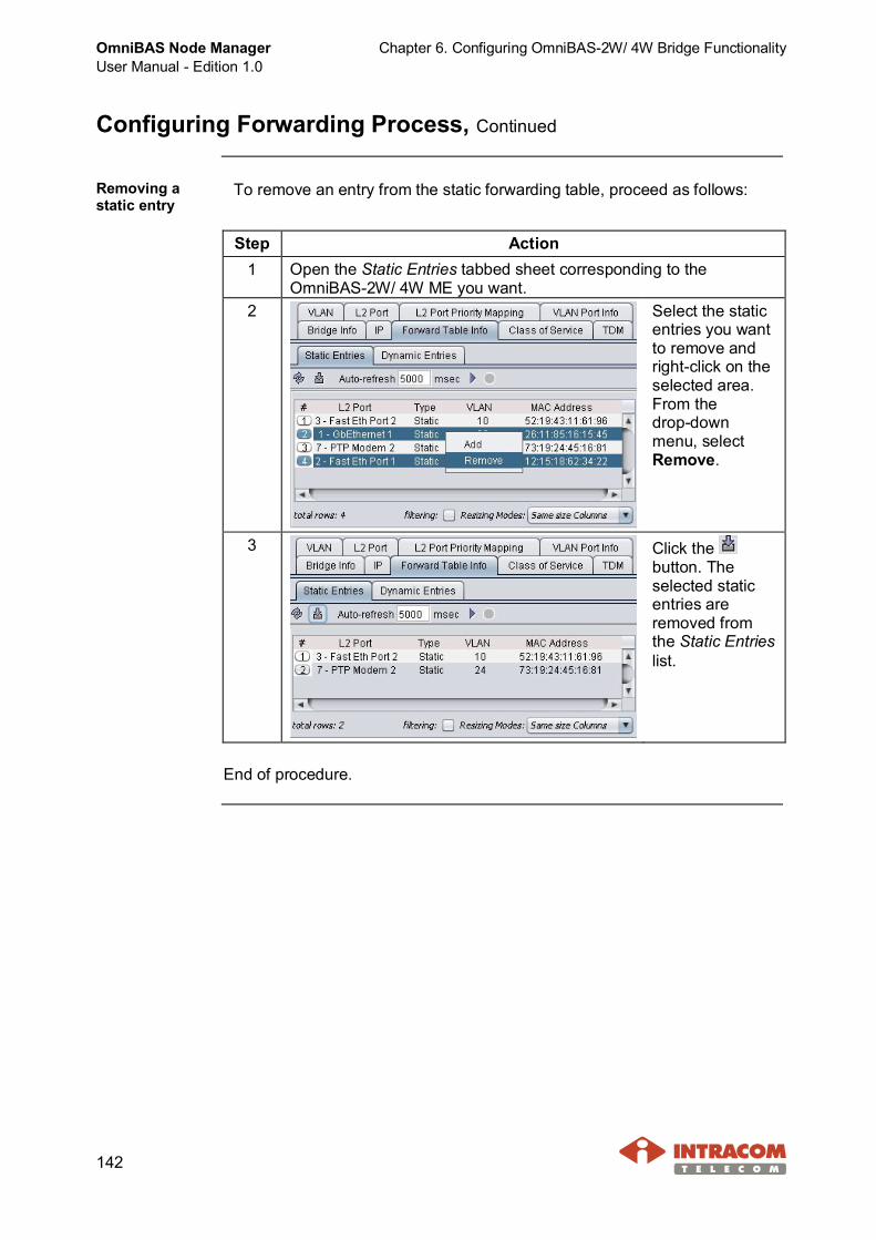
OmniBAS Node ManagerUser Manual - Edition 1.0
Chapter 6. Configuring OmniBAS-2W/ 4W Bridge Functionality
142
Configuring Forwarding Process, Continued
Removing astatic entry
To remove an entry from the static forwarding table, proceed as follows:
Step Action1 Open the Static Entries tabbed sheet corresponding to the
OmniBAS-2W/ 4W ME you want.2 Select the static
entries you wantto remove andright-click on theselected area.From thedrop-downmenu, selectRemove.
3 Click thebutton. Theselected staticentries areremoved fromthe Static Entrieslist.
End of procedure.
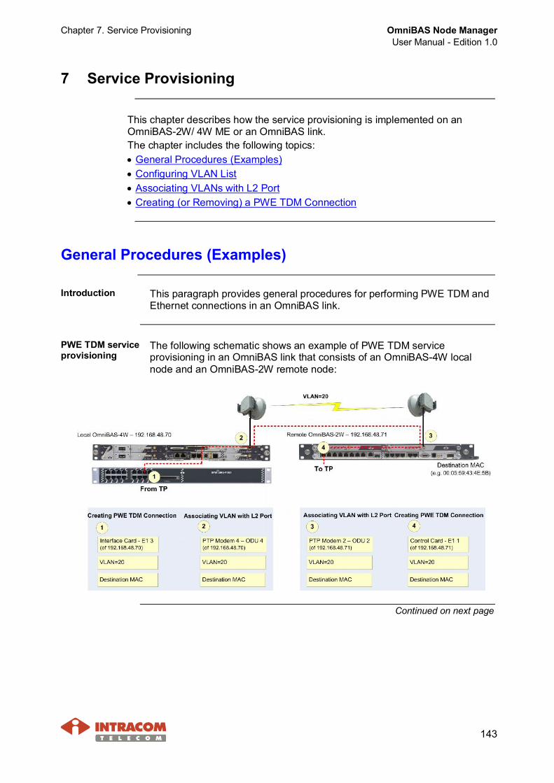
Chapter 7. Service Provisioning OmniBAS Node ManagerUser Manual - Edition 1.0
143
7 Service Provisioning
This chapter describes how the service provisioning is implemented on anOmniBAS-2W/ 4W ME or an OmniBAS link.The chapter includes the following topics:· General Procedures (Examples)· Configuring VLAN List· Associating VLANs with L2 Port· Creating (or Removing) a PWE TDM Connection
General Procedures (Examples)
Introduction This paragraph provides general procedures for performing PWE TDM andEthernet connections in an OmniBAS link.
PWE TDM serviceprovisioning
The following schematic shows an example of PWE TDM serviceprovisioning in an OmniBAS link that consists of an OmniBAS-4W localnode and an OmniBAS-2W remote node:
Continued on next page
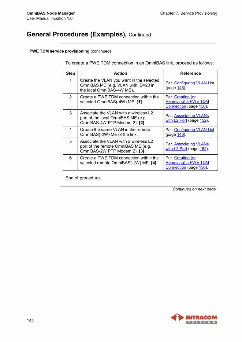
OmniBAS Node ManagerUser Manual - Edition 1.0
Chapter 7. Service Provisioning
144
General Procedures (Examples), Continued
PWE TDM service provisioning (continued)
To create a PWE TDM connection in an OmniBAS link, proceed as follows:
Step Action Reference1 Create the VLAN you want in the selected
OmniBAS ME (e.g. VLAN with ID=20 inthe local OmniBAS-4W ME).
Par. Configuring VLAN List(page 146).
2 Create a PWE TDM connection within theselected OmniBAS(-4W) ME. [1]
Par. Creating (orRemoving) a PWE TDMConnection (page 156).
3 Associate the VLAN with a wireless L2port of the local OmniBAS ME (e.g.OmniBAS-4W PTP Modem 2). [2]
Par. Associating VLANswith L2 Port (page 152).
4 Create the same VLAN in the remoteOmniBAS(-2W) ME of the link.
Par. Configuring VLAN List(page 146).
5 Associate the VLAN with a wireless L2port of the remote OmniBAS ME (e.g.OmniBAS-2W PTP Modem 2). [3]
Par. Associating VLANswith L2 Port (page 152).
6 Create a PWE TDM connection within theselected remote OmniBAS(-2W) ME. [4]
Par. Creating (orRemoving) a PWE TDMConnection (page 156).
End of procedure.
Continued on next page
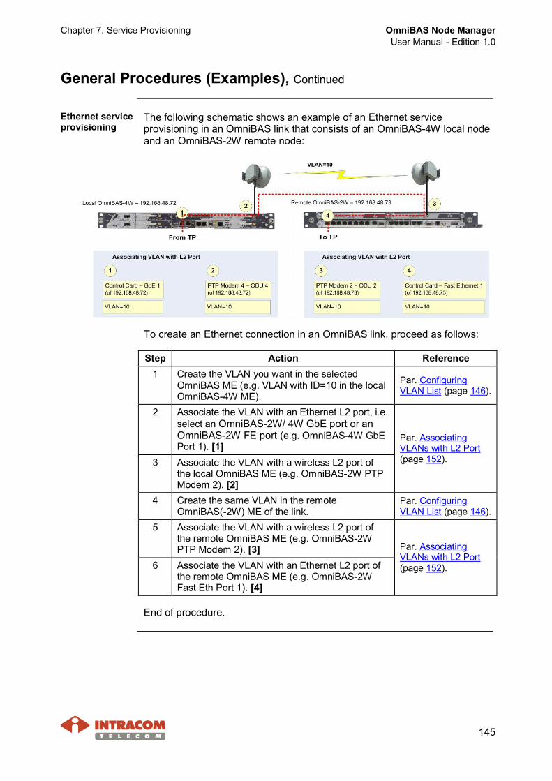
Chapter 7. Service Provisioning OmniBAS Node ManagerUser Manual - Edition 1.0
145
General Procedures (Examples), Continued
Ethernet serviceprovisioning
The following schematic shows an example of an Ethernet serviceprovisioning in an OmniBAS link that consists of an OmniBAS-4W local nodeand an OmniBAS-2W remote node:
To create an Ethernet connection in an OmniBAS link, proceed as follows:
Step Action Reference1 Create the VLAN you want in the selected
OmniBAS ME (e.g. VLAN with ID=10 in the localOmniBAS-4W ME).
Par. ConfiguringVLAN List (page 146).
2 Associate the VLAN with an Ethernet L2 port, i.e.select an OmniBAS-2W/ 4W GbE port or anOmniBAS-2W FE port (e.g. OmniBAS-4W GbEPort 1). [1]
3 Associate the VLAN with a wireless L2 port ofthe local OmniBAS ME (e.g. OmniBAS-2W PTPModem 2). [2]
Par. AssociatingVLANs with L2 Port(page 152).
4 Create the same VLAN in the remoteOmniBAS(-2W) ME of the link.
Par. ConfiguringVLAN List (page 146).
5 Associate the VLAN with a wireless L2 port ofthe remote OmniBAS ME (e.g. OmniBAS-2WPTP Modem 2). [3]
6 Associate the VLAN with an Ethernet L2 port ofthe remote OmniBAS ME (e.g. OmniBAS-2WFast Eth Port 1). [4]
Par. AssociatingVLANs with L2 Port(page 152).
End of procedure.
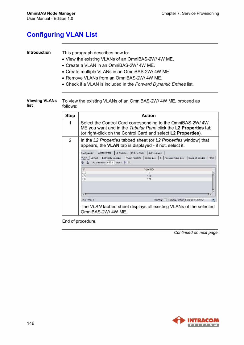
OmniBAS Node ManagerUser Manual - Edition 1.0
Chapter 7. Service Provisioning
146
Configuring VLAN List
Introduction This paragraph describes how to:· View the existing VLANs of an OmniBAS-2W/ 4W ME.· Create a VLAN in an OmniBAS-2W/ 4W ME.· Create multiple VLANs in an OmniBAS-2W/ 4W ME.· Remove VLANs from an OmniBAS-2W/ 4W ME.· Check if a VLAN is included in the Forward Dynamic Entries list.
Viewing VLANslist
To view the existing VLANs of an OmniBAS-2W/ 4W ME, proceed asfollows:
Step Action1 Select the Control Card corresponding to the OmniBAS-2W/ 4W
ME you want and in the Tabular Pane click the L2 Properties tab(or right-click on the Control Card and select L2 Properties).
2 In the L2 Properties tabbed sheet (or L2 Properties window) thatappears, the VLAN tab is displayed - if not, select it.
The VLAN tabbed sheet displays all existing VLANs of the selectedOmniBAS-2W/ 4W ME.
End of procedure.
Continued on next page
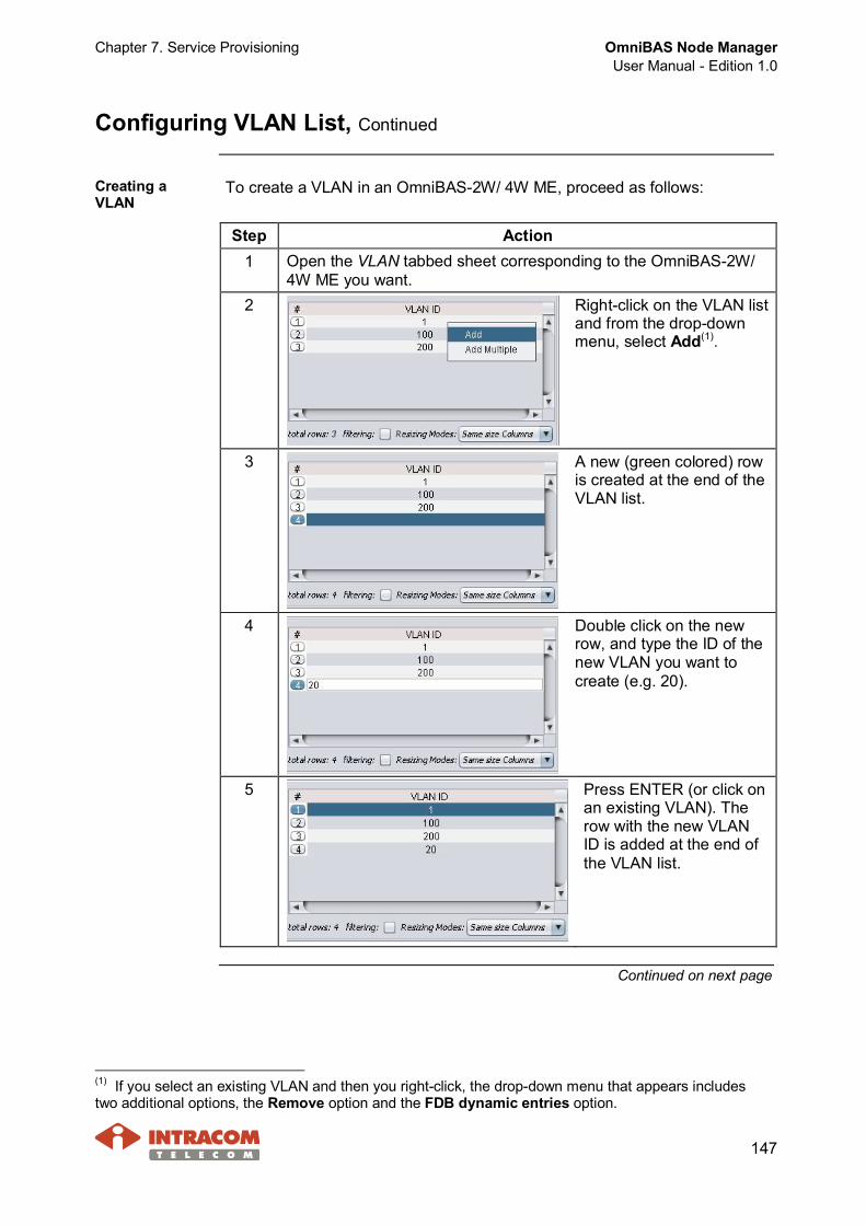
Chapter 7. Service Provisioning OmniBAS Node ManagerUser Manual - Edition 1.0
147
Configuring VLAN List, Continued
Creating aVLAN
To create a VLAN in an OmniBAS-2W/ 4W ME, proceed as follows:
Step Action1 Open the VLAN tabbed sheet corresponding to the OmniBAS-2W/
4W ME you want.2 Right-click on the VLAN list
and from the drop-downmenu, select Add(1).
3 A new (green colored) rowis created at the end of theVLAN list.
4 Double click on the newrow, and type the ID of thenew VLAN you want tocreate (e.g. 20).
5 Press ENTER (or click onan existing VLAN). Therow with the new VLANID is added at the end ofthe VLAN list.
Continued on next page
(1) If you select an existing VLAN and then you right-click, the drop-down menu that appears includestwo additional options, the Remove option and the FDB dynamic entries option.

OmniBAS Node ManagerUser Manual - Edition 1.0
Chapter 7. Service Provisioning
148
Configuring VLAN List, Continued
Creating a VLAN (continued)
Step Action6 Click the button.
The VLAN addition iscompleted successfullywhen the new VLAN isadded in the list gettingthe correspondingsequence number.
End of procedure.
Creating morethan one VLANs
To create more than one VLANs in an OmniBAS-2W/ 4W ME, proceed asfollows:
Step Action1 Open the VLAN tabbed sheet corresponding to the OmniBAS-2W/
4W ME you want.2 Right-click on the VLAN
list and from thedrop-down menu, selectAdd Multiple(1).
3 The Multiple Add window appears.
Type the VLAN IDs with commas between them. Also, use ahyphen (“-”) between the starting and ending VLAN IDs in a VLANIDs range. When you complete, close the window.
For example, to create the VLANs20, 22, 23, 24 and 28, type:20, 22-24, 28
Continued on next page
(1) If you select an existing VLAN and then you right-click, the drop-down menu that appears includestwo additional options, the Remove option and the FDB dynamic entries option.

Chapter 7. Service Provisioning OmniBAS Node ManagerUser Manual - Edition 1.0
149
Configuring VLAN List, Continued
Creating more than one VLANs (continued)
Step Action4 In the confirmation message
that appears, click Yes.
5 The new VLANs areadded at the end of theVLAN list.
6 Click the button.The VLANs addition iscompleted successfullywhen the new VLANsare added in the listgetting thecorrespondingsequence numbers.
End of procedure.
Continued on next page

OmniBAS Node ManagerUser Manual - Edition 1.0
Chapter 7. Service Provisioning
150
Configuring VLAN List, Continued
RemovingVLANs
To remove VLANs from an OmniBAS-2W/ 4W ME, proceed as follows:
NOTE Prior to removing a VLAN, ensure that:· It is not used as Default VLAN for any L2 port (check through the
L2 Port tabbed sheet).· No L2 port is already associated with this specific VLAN (check
through the VLAN Port Info tabbed sheet).
Step Action1 Open the VLAN tabbed sheet corresponding to the OmniBAS-2W/ 4W
ME you want.2 Select the VLANs you
want to remove andright-click on the selectedarea. From the drop-downmenu, select Remove.
3 Click the button. Theselected VLANs areremoved from the list.
End of procedure.
Continued on next page
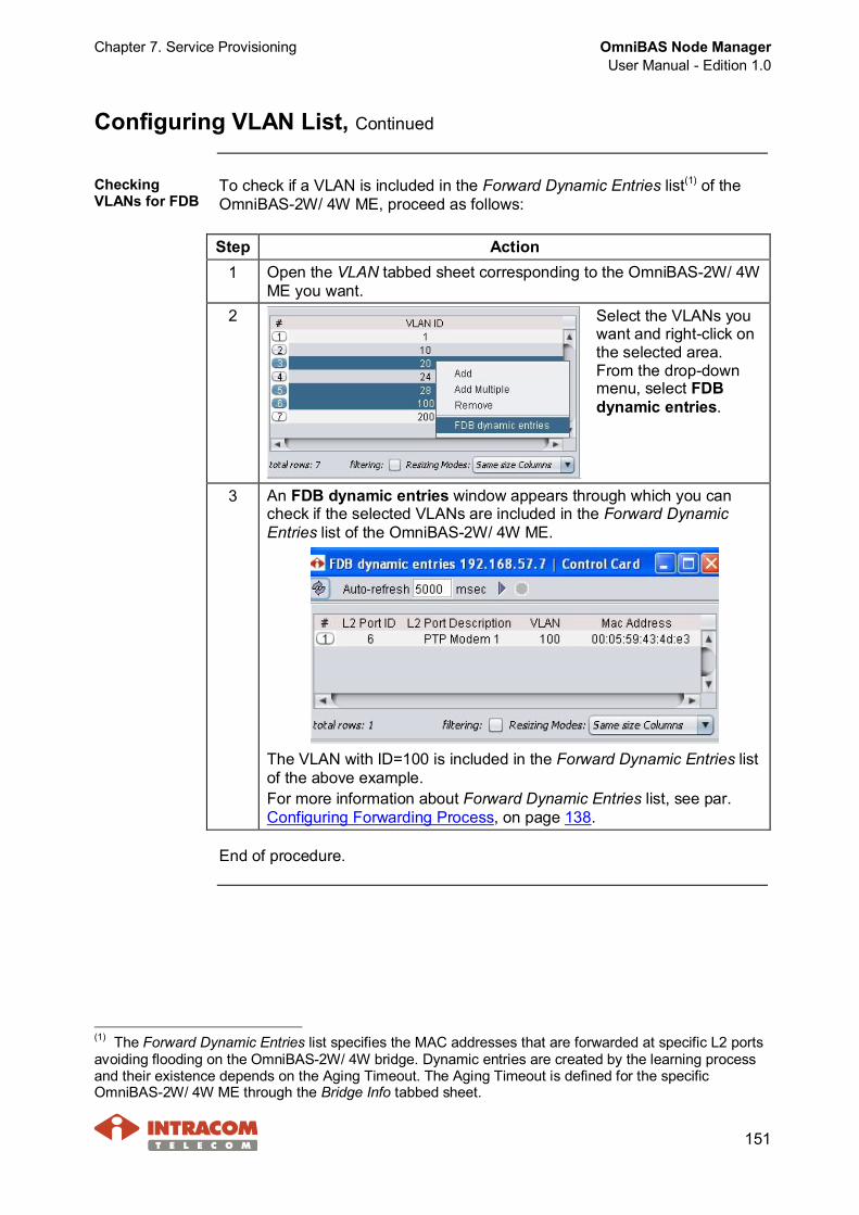
Chapter 7. Service Provisioning OmniBAS Node ManagerUser Manual - Edition 1.0
151
Configuring VLAN List, Continued
CheckingVLANs for FDB
To check if a VLAN is included in the Forward Dynamic Entries list(1) of theOmniBAS-2W/ 4W ME, proceed as follows:
Step Action1 Open the VLAN tabbed sheet corresponding to the OmniBAS-2W/ 4W
ME you want.2 Select the VLANs you
want and right-click onthe selected area.From the drop-downmenu, select FDBdynamic entries.
3 An FDB dynamic entries window appears through which you cancheck if the selected VLANs are included in the Forward DynamicEntries list of the OmniBAS-2W/ 4W ME.
The VLAN with ID=100 is included in the Forward Dynamic Entries listof the above example.For more information about Forward Dynamic Entries list, see par.Configuring Forwarding Process, on page 138.
End of procedure.
(1) The Forward Dynamic Entries list specifies the MAC addresses that are forwarded at specific L2 portsavoiding flooding on the OmniBAS-2W/ 4W bridge. Dynamic entries are created by the learning processand their existence depends on the Aging Timeout. The Aging Timeout is defined for the specificOmniBAS-2W/ 4W ME through the Bridge Info tabbed sheet.
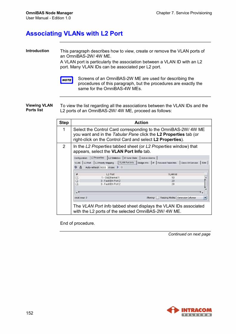
OmniBAS Node ManagerUser Manual - Edition 1.0
Chapter 7. Service Provisioning
152
Associating VLANs with L2 Port
Introduction This paragraph describes how to view, create or remove the VLAN ports ofan OmniBAS-2W/ 4W ME.A VLAN port is particularly the association between a VLAN ID with an L2port. Many VLAN IDs can be associated per L2 port.
NOTE Screens of an OmniBAS-2W ME are used for describing theprocedures of this paragraph, but the procedures are exactly thesame for the OmniBAS-4W MEs.
Viewing VLANPorts list
To view the list regarding all the associations between the VLAN IDs and theL2 ports of an OmniBAS-2W/ 4W ME, proceed as follows:
Step Action1 Select the Control Card corresponding to the OmniBAS-2W/ 4W ME
you want and in the Tabular Pane click the L2 Properties tab (orright-click on the Control Card and select L2 Properties).
2 In the L2 Properties tabbed sheet (or L2 Properties window) thatappears, select the VLAN Port Info tab.
The VLAN Port Info tabbed sheet displays the VLAN IDs associatedwith the L2 ports of the selected OmniBAS-2W/ 4W ME.
End of procedure.
Continued on next page

Chapter 7. Service Provisioning OmniBAS Node ManagerUser Manual - Edition 1.0
153
Associating VLANs with L2 Port, Continued
Associating aVLAN to L2 port
To associate VLANs with an L2 port, proceed as follows:
NOTE When a system is in S-VLAN bridging mode, then the L2 ports thatare configured as VLAN Transparent cannot be associated toVLANs.
Step Action1 Open the VLAN Port Info tabbed sheet corresponding to the
OmniBAS-2W/ 4W ME you want.2 Right-click on the VLAN
ports list and from thedrop-down menu, selectAdd (1).
3 A new row is created atthe end of the VLANports list.
4 Double click on the L2Port field and from thedrop-down list, selectthe L2 port you want(e.g. Fast Ethernet Port1).
Continued on next page
(1) If you select an existing VLAN port and then you right-click, the drop-down menu that appearsincludes also the Remove option.
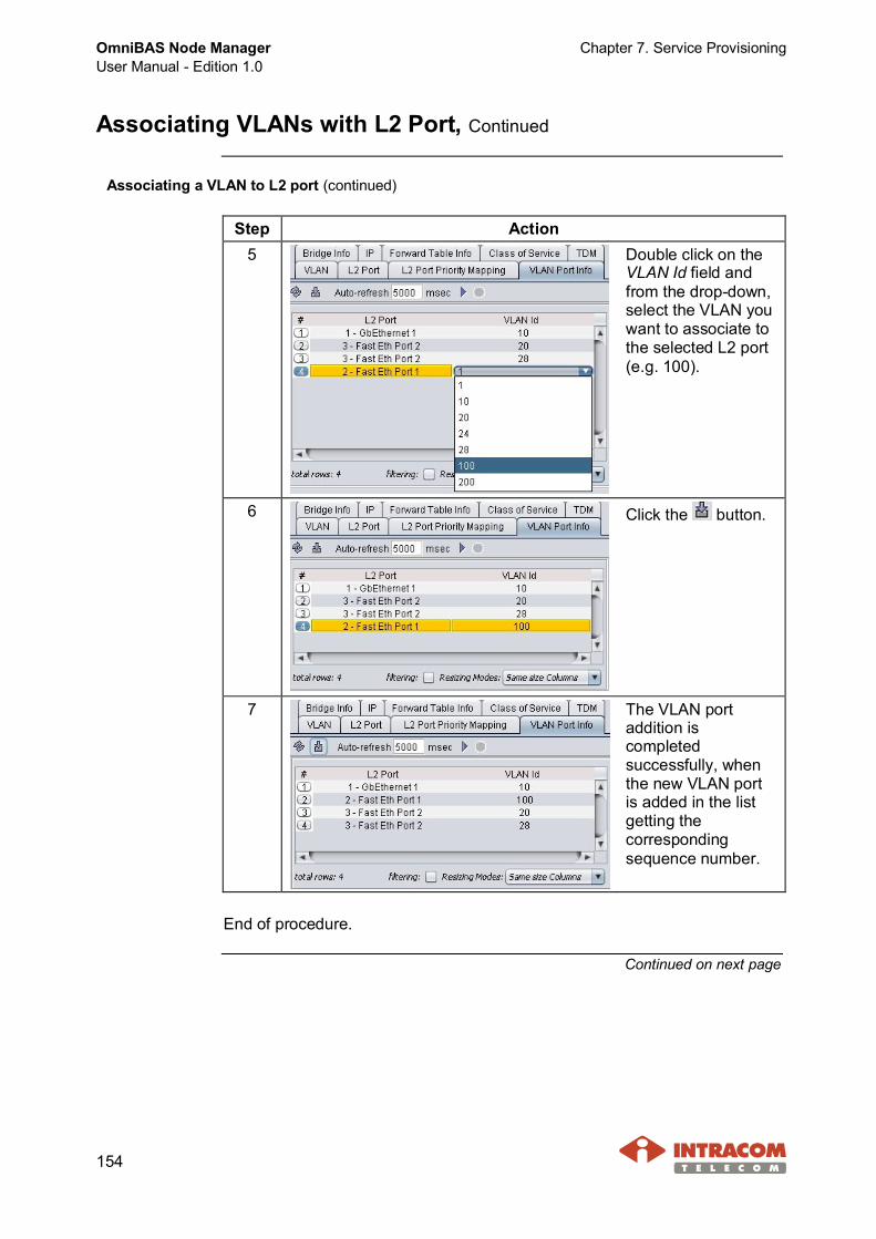
OmniBAS Node ManagerUser Manual - Edition 1.0
Chapter 7. Service Provisioning
154
Associating VLANs with L2 Port, Continued
Associating a VLAN to L2 port (continued)
Step Action5 Double click on the
VLAN Id field andfrom the drop-down,select the VLAN youwant to associate tothe selected L2 port(e.g. 100).
6 Click the button.
7 The VLAN portaddition iscompletedsuccessfully, whenthe new VLAN portis added in the listgetting thecorrespondingsequence number.
End of procedure.
Continued on next page
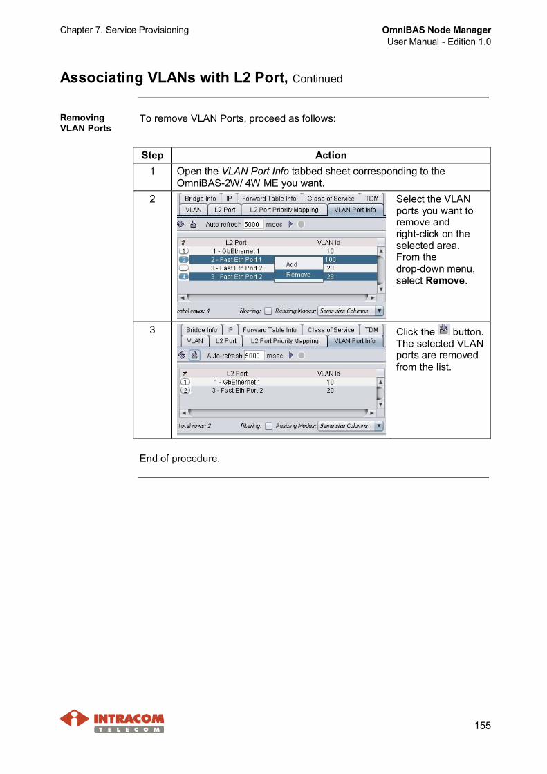
Chapter 7. Service Provisioning OmniBAS Node ManagerUser Manual - Edition 1.0
155
Associating VLANs with L2 Port, Continued
RemovingVLAN Ports
To remove VLAN Ports, proceed as follows:
Step Action1 Open the VLAN Port Info tabbed sheet corresponding to the
OmniBAS-2W/ 4W ME you want.2 Select the VLAN
ports you want toremove andright-click on theselected area.From thedrop-down menu,select Remove.
3 Click the button.The selected VLANports are removedfrom the list.
End of procedure.

OmniBAS Node ManagerUser Manual - Edition 1.0
Chapter 7. Service Provisioning
156
Creating (or Removing) a PWE TDM Connection
Introduction This paragraph describes:· How to create a PWE TDM connection within an OmniBAS-2W/ 4W ME.· How to remove a PWE TDM connection from an OmniBAS-2W/ 4W ME.
Adding a PWETDM connection
To create a PWE TDM connection within an OmniBAS-2W/ 4W ME,proceed as follows:
Step Action1 Select the Control Card corresponding to the OmniBAS-2W/ 4W
ME you want and in the Tabular Pane click the L2 Properties tab(or right-click on the Control Card and select L2 Properties).
2 In the L2 Properties tabbed sheet (or L2 Properties window) thatappears, select the TDM tab. The list of the existing PWE TDMconnections for the OmniBAS-2W/ 4W ME is displayed.
3 Right-click on the PWE TDM connections list and from thedrop-down menu, select Add (1).
Continued on next page
(1) If you select an existing PWE TDM connection and then you right-click, the drop-down menu thatappears includes two additional options, the Remove option and the Performance Measurements option.

Chapter 7. Service Provisioning OmniBAS Node ManagerUser Manual - Edition 1.0
157
Creating (or Removing) a PWE TDM Connection, Continued
Adding a PWE TDM connection (continued)
Step Action4 The TDM Creation
window appears.
5 From the E1 Port ID drop-down list, select the ID of the E1 port youwant to associate to the PWE TDM connection.
6 The PWE TDM connection to be created will be distinguished basedon ingress and egress Emulated Circuit Identifiers (ECID). If needed,you can change the ECID values suggested by application, by typingthe new ones in the Ingress and Egress text boxes.(Value range: 1 to 65535)
7 From the E1 Frame Type drop-down list, select the frame type of theselected E1 port:· Unstructured: Unstructured E1 provides stream of bits at 2048 kbit/s
(no framing support, i.e. no channels association with any specificgroup of bits).
· Doubleframe:- G.704 structured (consist of two standard-32 timeslots frames).- Timeslots TS1 to TS31 transfer payload. Frame synchronization is
carried over timeslot TS0.- No payload signaling is used.
· Multiframe CRC:- G.704 structured (consist of 16 standard-32 timeslots frames).- Timeslots TS1 to TS31 transfer payload. Frame synchronization is
carried over timeslot TS0.- No payload signaling is used.- The Si bits of each Frame Alignment Signal (FAS) are used to
implement CRC-4 control.
Continued on next page
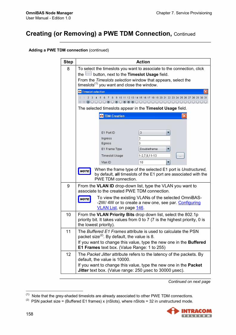
OmniBAS Node ManagerUser Manual - Edition 1.0
Chapter 7. Service Provisioning
158
Creating (or Removing) a PWE TDM Connection, Continued
Adding a PWE TDM connection (continued)
Step Action8 To select the timeslots you want to associate to the connection, click
the button, next to the Timeslot Usage field.From the Timeslots selection window that appears, select thetimeslots(1) you want and close the window.
The selected timeslots appear in the Timeslot Usage field.
NOTE When the frame type of the selected E1 port is Unstructured,by default, all timeslots of the E1 port are associated with thePWE TDM connection.
9 From the VLAN ID drop-down list, type the VLAN you want toassociate to the created PWE TDM connection.
NOTE To view the existing VLANs of the selected OmniBAS--2W/ 4W or to create a new one, see par. ConfiguringVLAN List, on page 146.
10 From the VLAN Priority Bits drop down list, select the 802.1ppriority bit. It takes values from 0 to 7 (7 is the highest priority, 0 isthe lowest priority).
11 The Buffered E1 Frames attribute is used to calculate the PSNpacket size(2). By default, the value is 8.If you want to change this value, type the new one in the BufferedE1 Frames text box. (Value Range: 1 to 255)
12 The Packet Jitter attribute refers to the latency of the packets. Bydefault, the value is 10000.If you want to change this value, type the new one in the PacketJitter text box. (Value range: 250 μsec to 30000 μsec).
Continued on next page
(1) Note that the grey-shaded timeslots are already associated to other PWE TDM connections.(2) PSN packet size = (Buffered E1 frames) x (nSlots), where nSlots = 32 in unstructured mode.

Chapter 7. Service Provisioning OmniBAS Node ManagerUser Manual - Edition 1.0
159
Creating (or Removing) a PWE TDM Connection, Continued
Adding a PWE TDM connection (continued)
Step Action13 In the Destination MAC Address text box, enter the MAC address of
the OmniBAS-2W/ 4W ME on which the created PWE TDM connectionterminates.
NOTE To identify this MAC address:· Select the OmniBAS Card on which the created PWE
TDM connection terminates (OmniBAS-2W Control Cardor OmniBAS-4W Interface Card).
· If you select an OmniBAS-2W Control Card:In the Tabular Pane click the Configuration tab (orright-click on the Control Card and selectConfiguration). In the Configuration tabbed sheet (orConfiguration Data window) that appears, select theInterface Configuration tab. The MAC address isdisplayed in this tabbed sheet.
· If you select an OmniBAS-4W Interface Card:In the Tabular Pane click the Configuration tab andthen the Configuration Information tab. The MACaddress is displayed in the Configuration Informationtabbed sheet. (Alternatively, right-click on the InterfaceCard and select Configuration Data. The MAC addressis displayed in the Configuration Data window thatappears).
14 When you complete, click the Ok button. The new PWE TDMconnection is added in the TDM tabbed sheet.
15 In the TDM tabbed sheet, click the button to apply the new PWETDM connection.
End of procedure.
Continued on next page

OmniBAS Node ManagerUser Manual - Edition 1.0
Chapter 7. Service Provisioning
160
Creating (or Removing) a PWE TDM Connection, Continued
Removing PWETDMconnections
To remove PWE TDM connections from an OmniBAS-2W/ 4W ME, proceedas follows:
Step Action1 Open the TDM tabbed sheet corresponding to the OmniBAS-2W/
4W ME you want.2 Select the PWE TDM connections you want to remove and
right-click on the selected area. From the drop-down menu, selectRemove.
3 Click the button. The selected PWE TDM connections areremoved from the list.
End of procedure.

Chapter 8. Loopback Tests OmniBAS Node ManagerUser Manual - Edition 1.0
161
8 Loopback Tests
This chapter refers to the loopback capabilities of the OmniBAS NodeManager. The loopbacks that can be set by the application, concern:· 8 x E1 lines provided by the OmniBAS-2W Control Card· 16 x E1 lines provided by the OmniBAS-4W Interface Card· OmniBAS-2W/ 4W ODUs
Performing Loopback Tests in E1 Lines
Introduction This paragraph describes the loopback tests that can be performed on theOmniBAS-2W/ 4W E1 lines.
OmniBAS-2Wloopbacks
The following loopback tests can be performed for troubleshooting purposes,when fault is detected on an OmniBAS-2W E1 line.As the following schematic shows:· For a local OmniBAS-2W node two loopback types (LIU and Framer) are
available.· For a remote OmniBAS-2W node the Framer loopback type is available.
Continued on next page
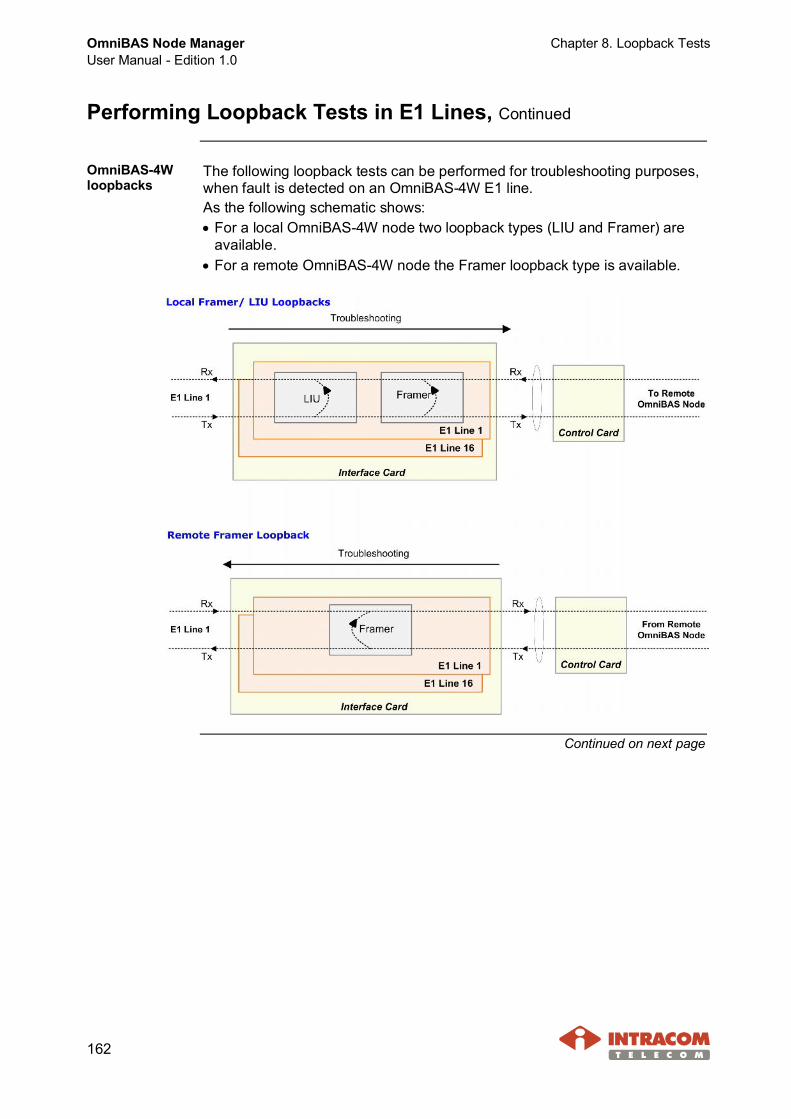
OmniBAS Node ManagerUser Manual - Edition 1.0
Chapter 8. Loopback Tests
162
Performing Loopback Tests in E1 Lines, Continued
OmniBAS-4Wloopbacks
The following loopback tests can be performed for troubleshooting purposes,when fault is detected on an OmniBAS-4W E1 line.As the following schematic shows:· For a local OmniBAS-4W node two loopback types (LIU and Framer) are
available.· For a remote OmniBAS-4W node the Framer loopback type is available.
Continued on next page
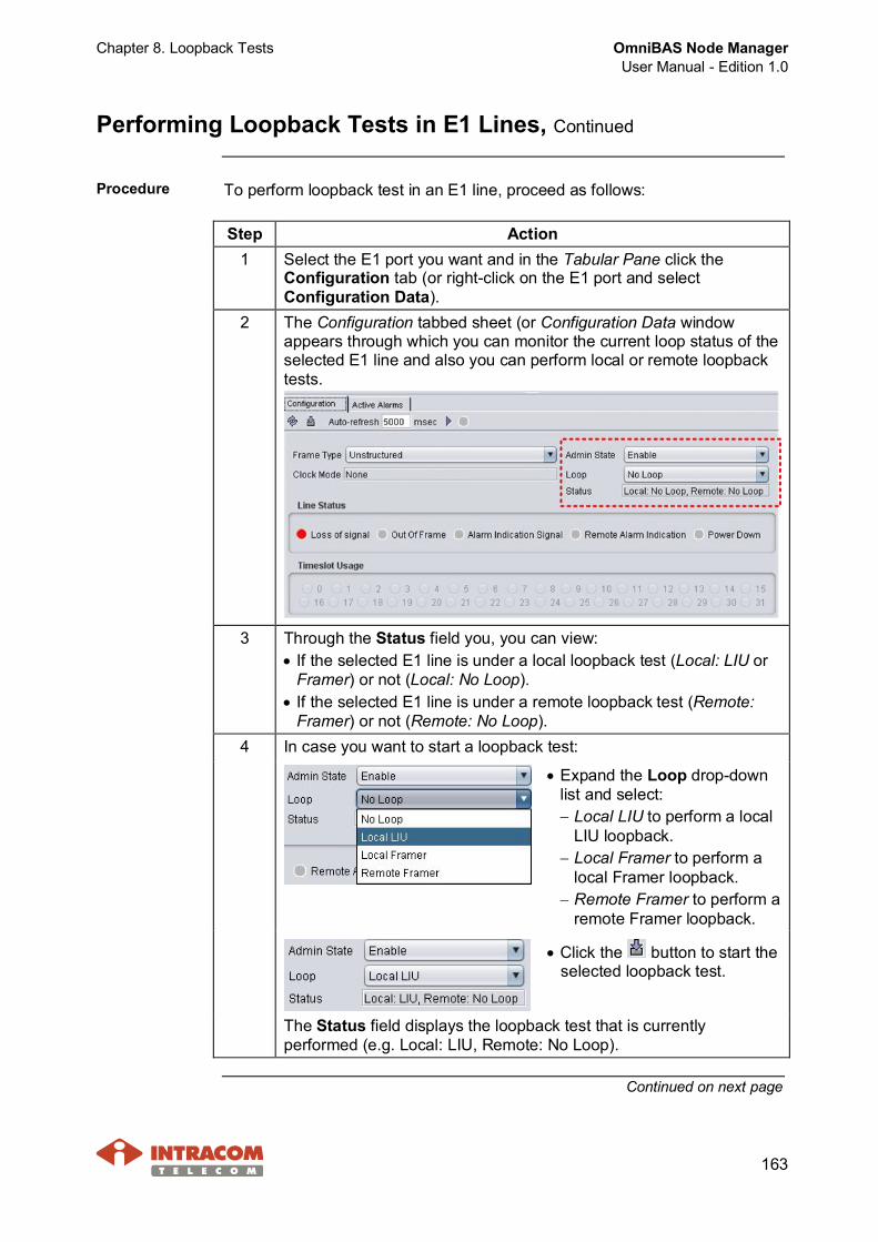
Chapter 8. Loopback Tests OmniBAS Node ManagerUser Manual - Edition 1.0
163
Performing Loopback Tests in E1 Lines, Continued
Procedure To perform loopback test in an E1 line, proceed as follows:
Step Action1 Select the E1 port you want and in the Tabular Pane click the
Configuration tab (or right-click on the E1 port and selectConfiguration Data).
2 The Configuration tabbed sheet (or Configuration Data windowappears through which you can monitor the current loop status of theselected E1 line and also you can perform local or remote loopbacktests.
3 Through the Status field you, you can view:· If the selected E1 line is under a local loopback test (Local: LIU or
Framer) or not (Local: No Loop).· If the selected E1 line is under a remote loopback test (Remote:
Framer) or not (Remote: No Loop).4 In case you want to start a loopback test:
· Expand the Loop drop-downlist and select:- Local LIU to perform a local
LIU loopback.- Local Framer to perform a
local Framer loopback.- Remote Framer to perform a
remote Framer loopback.
· Click the button to start theselected loopback test.
The Status field displays the loopback test that is currentlyperformed (e.g. Local: LIU, Remote: No Loop).
Continued on next page
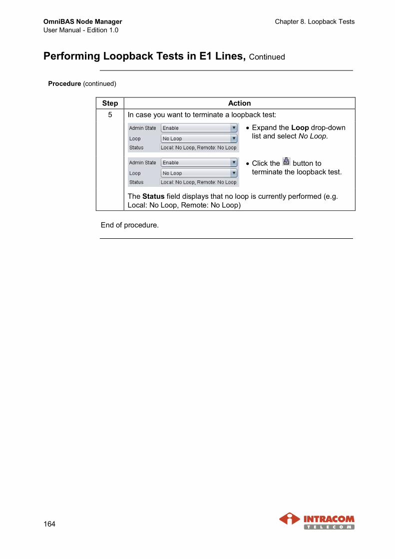
OmniBAS Node ManagerUser Manual - Edition 1.0
Chapter 8. Loopback Tests
164
Performing Loopback Tests in E1 Lines, Continued
Procedure (continued)
Step Action5 In case you want to terminate a loopback test:
· Expand the Loop drop-downlist and select No Loop.
· Click the button toterminate the loopback test.
The Status field displays that no loop is currently performed (e.g.Local: No Loop, Remote: No Loop)
End of procedure.
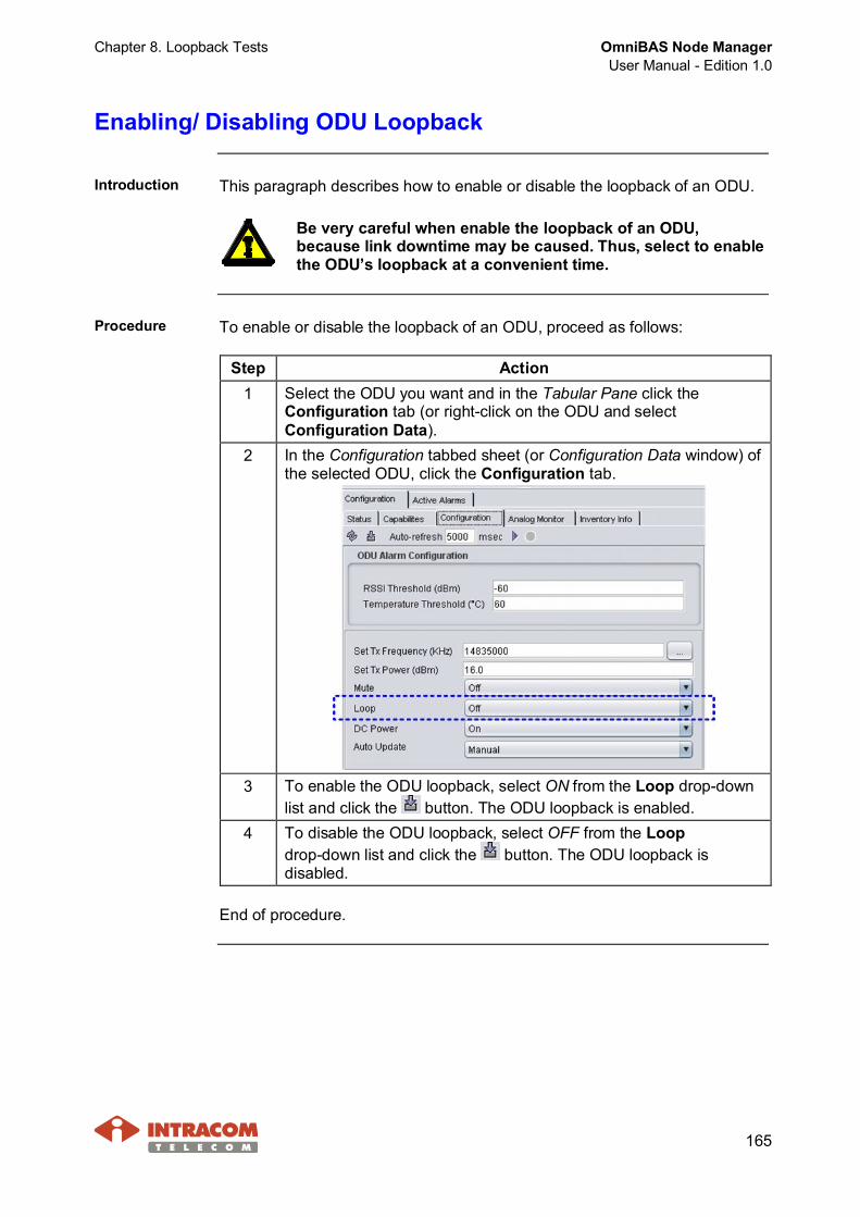
Chapter 8. Loopback Tests OmniBAS Node ManagerUser Manual - Edition 1.0
165
Enabling/ Disabling ODU Loopback
Introduction This paragraph describes how to enable or disable the loopback of an ODU.
Be very careful when enable the loopback of an ODU,because link downtime may be caused. Thus, select to enablethe ODU’s loopback at a convenient time.
Procedure To enable or disable the loopback of an ODU, proceed as follows:
Step Action1 Select the ODU you want and in the Tabular Pane click the
Configuration tab (or right-click on the ODU and selectConfiguration Data).
2 In the Configuration tabbed sheet (or Configuration Data window) ofthe selected ODU, click the Configuration tab.
3 To enable the ODU loopback, select ON from the Loop drop-downlist and click the button. The ODU loopback is enabled.
4 To disable the ODU loopback, select OFF from the Loopdrop-down list and click the button. The ODU loopback isdisabled.
End of procedure.
OmniBAS Node ManagerUser Manual - Edition 1.0
Chapter 9. Maintaining the OmniBAS-2W/ 4W MEs
166
9 Maintaining the OmniBAS-2W/ 4W MEs
This chapter provides the following procedures that are carried out whenrequired for maintaining the OmniBAS-2W/ 4W MEs:· Saving OmniBAS-2W/ 4W ME Configuration· Synchronizing an OmniBAS-2W/ 4W ME· Adding/ Removing a Trap Destination· Performing a Backup or Restore Action· Upgrading the Firmware of an OmniBAS· Updating an ODU

Chapter 9. Maintaining the OmniBAS-2W/ 4W MEs OmniBAS Node ManagerUser Manual - Edition 1.0
167
Saving OmniBAS-2W/ 4W ME Configuration
Introduction This paragraph describes how to store the configuration of an OmniBAS-2W/4W ME in the Control Card of the OmniBAS-2W/ 4W equipment. This actionmakes sure that the OmniBAS-2W/ 4W ME preserves its configuration afterOmniBAS-2W/ 4W ME reset.
Procedure To save the configuration of an OmniBAS-2W/ 4W ME, proceed as follows:
Step Action1 Right-click on the OmniBAS-2W/ 4W ME you want and from the
drop-down menu, select Configuration > Save Configuration.2 In the following confirmation message that appears, click Yes to
continue.
The settings and the configuration of the OmniBAS-2W/ 4W ME isnow saved.
End of procedure.
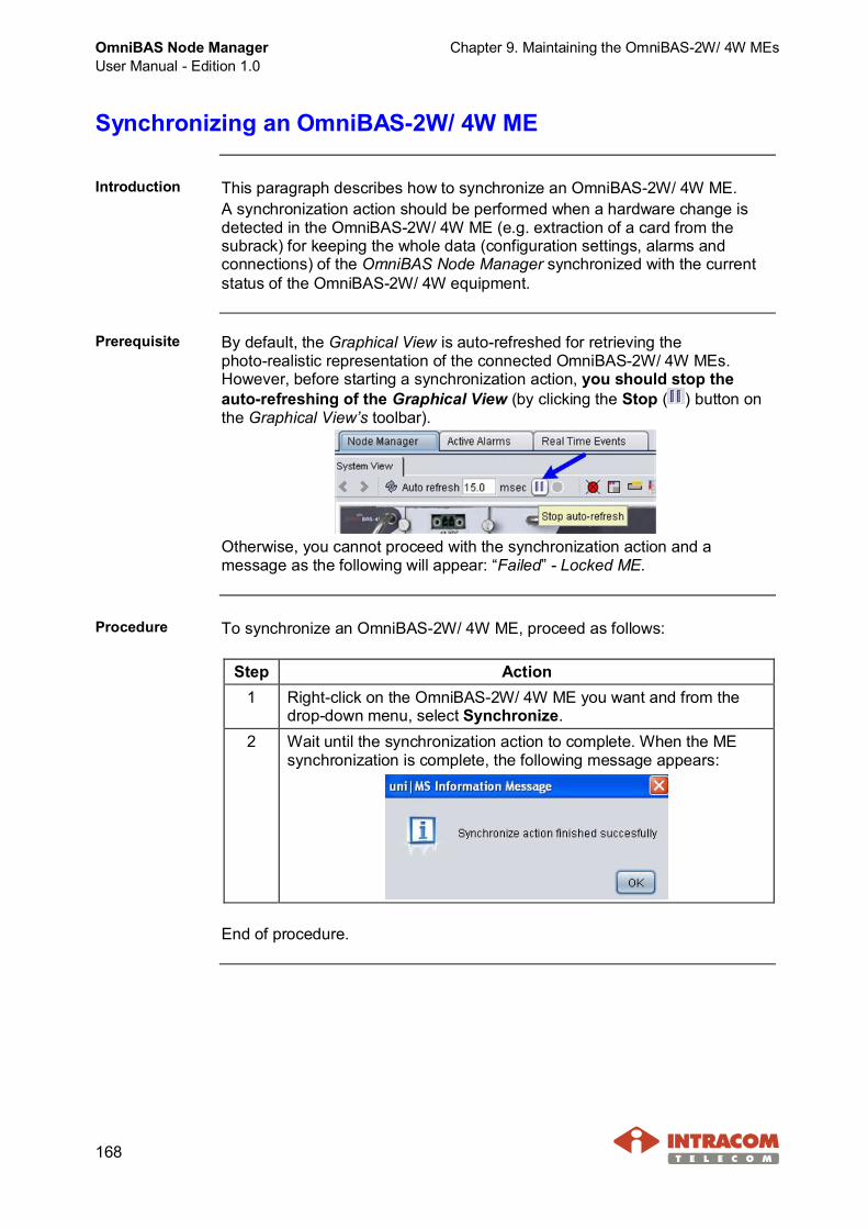
OmniBAS Node ManagerUser Manual - Edition 1.0
Chapter 9. Maintaining the OmniBAS-2W/ 4W MEs
168
Synchronizing an OmniBAS-2W/ 4W ME
Introduction This paragraph describes how to synchronize an OmniBAS-2W/ 4W ME.A synchronization action should be performed when a hardware change isdetected in the OmniBAS-2W/ 4W ME (e.g. extraction of a card from thesubrack) for keeping the whole data (configuration settings, alarms andconnections) of the OmniBAS Node Manager synchronized with the currentstatus of the OmniBAS-2W/ 4W equipment.
Prerequisite By default, the Graphical View is auto-refreshed for retrieving thephoto-realistic representation of the connected OmniBAS-2W/ 4W MEs.However, before starting a synchronization action, you should stop theauto-refreshing of the Graphical View (by clicking the Stop ( ) button onthe Graphical View’s toolbar).
Otherwise, you cannot proceed with the synchronization action and amessage as the following will appear: “Failed” - Locked ME.
Procedure To synchronize an OmniBAS-2W/ 4W ME, proceed as follows:
Step Action1 Right-click on the OmniBAS-2W/ 4W ME you want and from the
drop-down menu, select Synchronize.2 Wait until the synchronization action to complete. When the ME
synchronization is complete, the following message appears:
End of procedure.
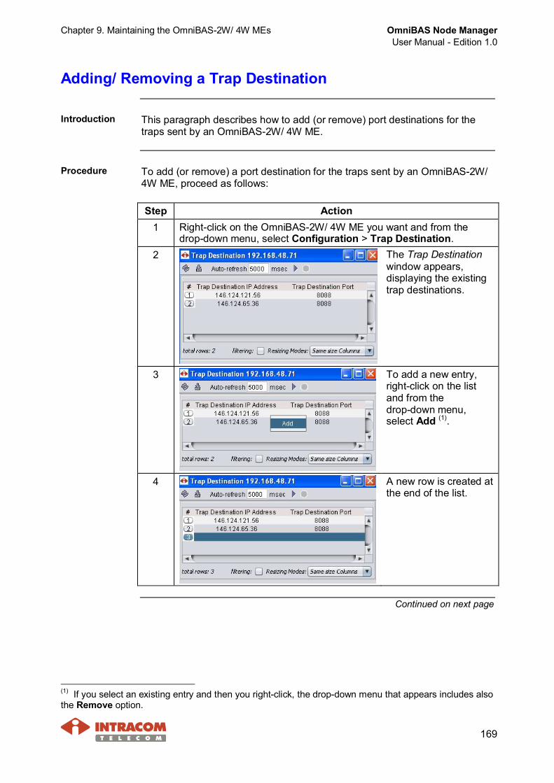
Chapter 9. Maintaining the OmniBAS-2W/ 4W MEs OmniBAS Node ManagerUser Manual - Edition 1.0
169
Adding/ Removing a Trap Destination
Introduction This paragraph describes how to add (or remove) port destinations for thetraps sent by an OmniBAS-2W/ 4W ME.
Procedure To add (or remove) a port destination for the traps sent by an OmniBAS-2W/4W ME, proceed as follows:
Step Action1 Right-click on the OmniBAS-2W/ 4W ME you want and from the
drop-down menu, select Configuration > Trap Destination.2 The Trap Destination
window appears,displaying the existingtrap destinations.
3 To add a new entry,right-click on the listand from thedrop-down menu,select Add (1).
4 A new row is created atthe end of the list.
Continued on next page
(1) If you select an existing entry and then you right-click, the drop-down menu that appears includes alsothe Remove option.
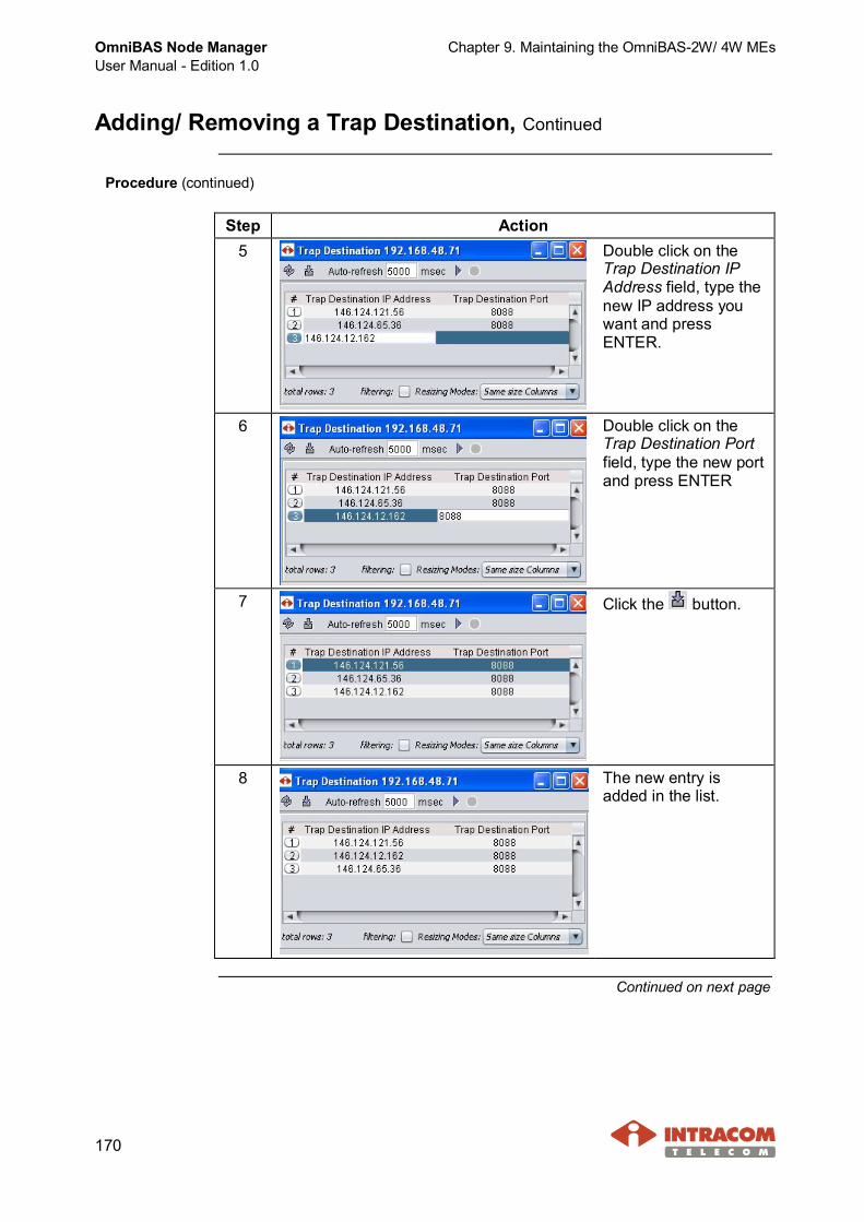
OmniBAS Node ManagerUser Manual - Edition 1.0
Chapter 9. Maintaining the OmniBAS-2W/ 4W MEs
170
Adding/ Removing a Trap Destination, Continued
Procedure (continued)
Step Action5 Double click on the
Trap Destination IPAddress field, type thenew IP address youwant and pressENTER.
6 Double click on theTrap Destination Portfield, type the new portand press ENTER
7 Click the button.
8 The new entry isadded in the list.
Continued on next page

Chapter 9. Maintaining the OmniBAS-2W/ 4W MEs OmniBAS Node ManagerUser Manual - Edition 1.0
171
Adding/ Removing a Trap Destination, Continued
Procedure (continued)
Step Action9 To remove an entry
from the list:· Select the entries you
want to remove andright-click on theselected area. Fromthe drop-down menu,select Remove.
· Click the button. The selected entries are removed from the list.
End of procedure.

OmniBAS Node ManagerUser Manual - Edition 1.0
Chapter 9. Maintaining the OmniBAS-2W/ 4W MEs
172
Performing a Backup or Restore Action
Introduction This paragraph describes:· How to backup the configuration of an OmniBAS-2W/ 4W ME, i.e. how to
get the current configuration from the OmniBAS-2W/ 4W equipment locallyto your PC/ Laptop.
· How to restore the configuration of an OmniBAS-2W/ 4W ME, i.e. how toget the previously backed-up configuration from your PC/ Laptop to theOmniBAS-2W/ 4W equipment.
Prerequisite By default, the Graphical View is auto-refreshed for retrieving thephoto-realistic representation of the connected OmniBAS-2W/ 4W MEs.However, before starting a backup or restore action, you should stop theauto-refreshing of the Graphical View (by clicking the Stop ( ) button onthe Graphical View’s toolbar).
Otherwise, you cannot proceed with the backup or restore action and amessage as the following will appear: “Failed” - Locked ME.
Continued on next page

Chapter 9. Maintaining the OmniBAS-2W/ 4W MEs OmniBAS Node ManagerUser Manual - Edition 1.0
173
Performing a Backup or Restore Action, Continued
Backupprocedure
To backup the configuration of an OmniBAS-2W/ 4W ME, proceed asfollows:
Step Action1 Right-click on the OmniBAS-2W/ 4W ME you want and from the
drop-down menu, select Configuration > Backup Configuration.2 Wait until the backup action to
complete. Upon successfulexecution of the action, acorresponding informationmessage appears.
3 The configuration files(.cfg) are uploadedfrom the OmniBAS-2W/4W equipment locallyto your PC/ Laptop (inthe configBackupfolder that is createdunder the nm directoryof the OmniBAS NodeManager application).
End of procedure.
Continued on next page

OmniBAS Node ManagerUser Manual - Edition 1.0
Chapter 9. Maintaining the OmniBAS-2W/ 4W MEs
174
Performing a Backup or Restore Action, Continued
Restoreprocedure
To restore the configuration of an OmniBAS-2W/ 4W ME, proceed as follows:
Step Action1 Right-click on the OmniBAS-2W/ 4W ME you want and from the
drop-down menu, select Configuration > Restore Configuration.2 In the message that appears, click OK to continue.
This message informs you that after restore procedure has beencompleted, you should reset the OmniBAS-2W/ 4W ME for theconfiguration restore to take effect.
3 In the Restore Configurationwindow that appears, selectthe .cfg files (or thecorresponding directory) andclick the Download button.
4 Wait until the configuration to berestored. In the correspondingmessage that appears, click Ok.
5 To complete the restore procedure, you should reset the OmniBAS-2W/4W ME as described in par. Resetting an OmniBAS-2W/ 4W ME, onpage 181.
Be very careful when you perform a reset action on theOmniBAS-2W/ 4W ME, because traffic loss will occur.
End of procedure.

Chapter 9. Maintaining the OmniBAS-2W/ 4W MEs OmniBAS Node ManagerUser Manual - Edition 1.0
175
Upgrading the Firmware of an OmniBAS Link
Introduction This paragraph describes how to upgrade both nodes of an OmniBAS linkwith a new firmware release.
The upgrading process on an OmniBAS link must start from theremote OmniBAS-2W/ 4W node. Otherwise, communication losswith the remote node may take place and a visit to the site will berequired.
After the completion of the upgrading process on an OmniBAS-2W/4W node, a reset action should be performed on the node for thefirmware upgrade process to take effect. During reboot, traffic losswill occur.
During the upgrading process, the OmniBAS link will be down forseveral minutes and thus select to perform the upgrading at aconvenient time.
NOTE When upgrading the firmware of an OmniBAS-2W/ 4W ME, itsconfiguration is not lost if it has been saved.
Getting newfirmwarerelease
After request, INTRACOM TELECOM provides you the new firmware releaseof the OmniBAS-2W/ 4W system. Prior to proceeding with the upgradingprocedure, you should copy the provided files to your PC/ laptop, retaining theoriginal file structure.
The firmware upgrade files should be copiedin the folder:· nm / files / fwfiles / omnibas2wME, in case
of OmniBAS-2W upgrading.· nm / files / fwfiles / omnibaswME, in case
of OmniBAS-4W upgrading.
Continued on next page
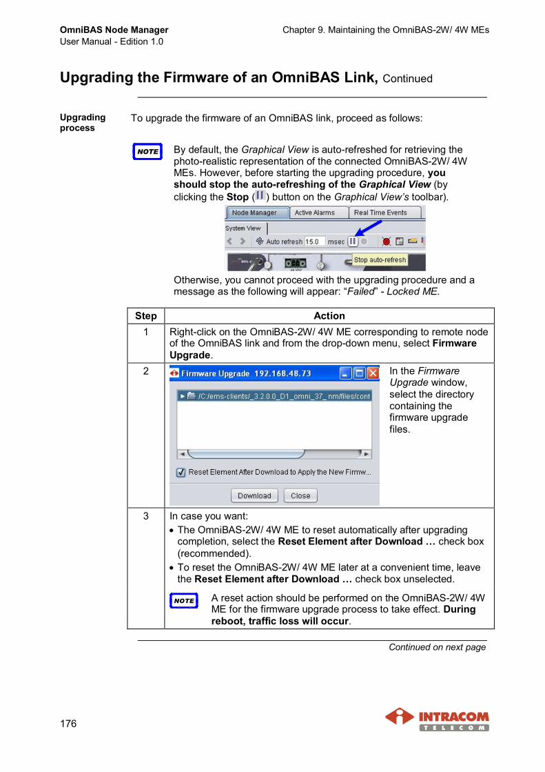
OmniBAS Node ManagerUser Manual - Edition 1.0
Chapter 9. Maintaining the OmniBAS-2W/ 4W MEs
176
Upgrading the Firmware of an OmniBAS Link, Continued
Upgradingprocess
To upgrade the firmware of an OmniBAS link, proceed as follows:
NOTE By default, the Graphical View is auto-refreshed for retrieving thephoto-realistic representation of the connected OmniBAS-2W/ 4WMEs. However, before starting the upgrading procedure, youshould stop the auto-refreshing of the Graphical View (byclicking the Stop ( ) button on the Graphical View’s toolbar).
Otherwise, you cannot proceed with the upgrading procedure and amessage as the following will appear: “Failed” - Locked ME.
Step Action1 Right-click on the OmniBAS-2W/ 4W ME corresponding to remote node
of the OmniBAS link and from the drop-down menu, select FirmwareUpgrade.
2 In the FirmwareUpgrade window,select the directorycontaining thefirmware upgradefiles.
3 In case you want:· The OmniBAS-2W/ 4W ME to reset automatically after upgrading
completion, select the Reset Element after Download … check box(recommended).
· To reset the OmniBAS-2W/ 4W ME later at a convenient time, leavethe Reset Element after Download … check box unselected.
NOTE A reset action should be performed on the OmniBAS-2W/ 4WME for the firmware upgrade process to take effect. Duringreboot, traffic loss will occur.
Continued on next page
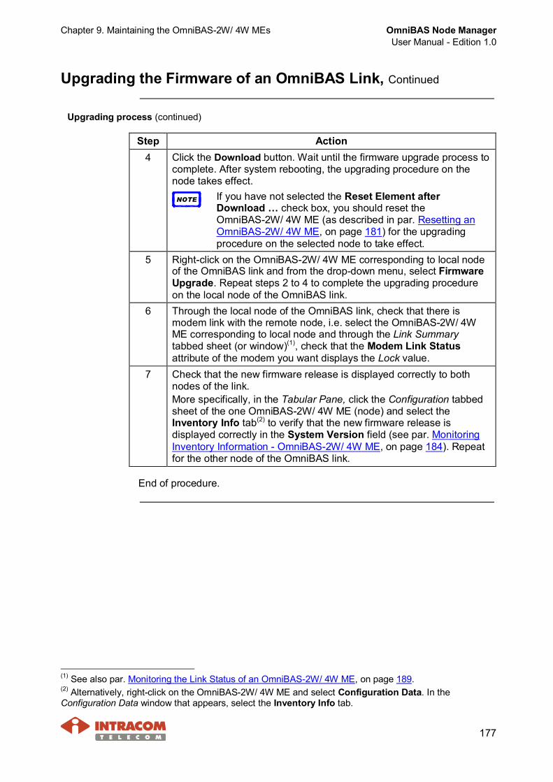
Chapter 9. Maintaining the OmniBAS-2W/ 4W MEs OmniBAS Node ManagerUser Manual - Edition 1.0
177
Upgrading the Firmware of an OmniBAS Link, Continued
Upgrading process (continued)
Step Action4 Click the Download button. Wait until the firmware upgrade process to
complete. After system rebooting, the upgrading procedure on thenode takes effect.
NOTE If you have not selected the Reset Element afterDownload … check box, you should reset theOmniBAS-2W/ 4W ME (as described in par. Resetting anOmniBAS-2W/ 4W ME, on page 181) for the upgradingprocedure on the selected node to take effect.
5 Right-click on the OmniBAS-2W/ 4W ME corresponding to local nodeof the OmniBAS link and from the drop-down menu, select FirmwareUpgrade. Repeat steps 2 to 4 to complete the upgrading procedureon the local node of the OmniBAS link.
6 Through the local node of the OmniBAS link, check that there ismodem link with the remote node, i.e. select the OmniBAS-2W/ 4WME corresponding to local node and through the Link Summarytabbed sheet (or window)(1), check that the Modem Link Statusattribute of the modem you want displays the Lock value.
7 Check that the new firmware release is displayed correctly to bothnodes of the link.More specifically, in the Tabular Pane, click the Configuration tabbedsheet of the one OmniBAS-2W/ 4W ME (node) and select theInventory Info tab(2) to verify that the new firmware release isdisplayed correctly in the System Version field (see par. MonitoringInventory Information - OmniBAS-2W/ 4W ME, on page 184). Repeatfor the other node of the OmniBAS link.
End of procedure.
(1) See also par. Monitoring the Link Status of an OmniBAS-2W/ 4W ME, on page 189.(2) Alternatively, right-click on the OmniBAS-2W/ 4W ME and select Configuration Data. In theConfiguration Data window that appears, select the Inventory Info tab.
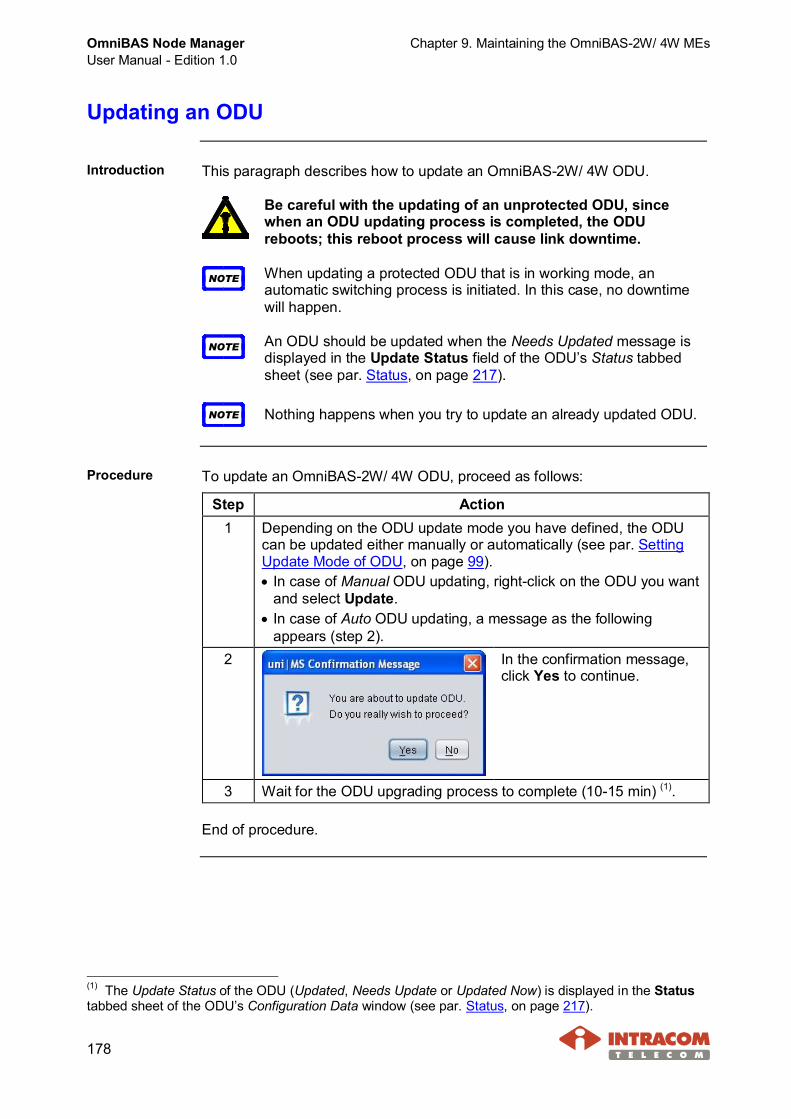
OmniBAS Node ManagerUser Manual - Edition 1.0
Chapter 9. Maintaining the OmniBAS-2W/ 4W MEs
178
Updating an ODU
Introduction This paragraph describes how to update an OmniBAS-2W/ 4W ODU.
Be careful with the updating of an unprotected ODU, sincewhen an ODU updating process is completed, the ODUreboots; this reboot process will cause link downtime.
NOTE When updating a protected ODU that is in working mode, anautomatic switching process is initiated. In this case, no downtimewill happen.
NOTE An ODU should be updated when the Needs Updated message isdisplayed in the Update Status field of the ODU’s Status tabbedsheet (see par. Status, on page 217).
NOTE Nothing happens when you try to update an already updated ODU.
Procedure To update an OmniBAS-2W/ 4W ODU, proceed as follows:
Step Action1 Depending on the ODU update mode you have defined, the ODU
can be updated either manually or automatically (see par. SettingUpdate Mode of ODU, on page 99).· In case of Manual ODU updating, right-click on the ODU you want
and select Update.· In case of Auto ODU updating, a message as the following
appears (step 2).2 In the confirmation message,
click Yes to continue.
3 Wait for the ODU upgrading process to complete (10-15 min) (1).
End of procedure.
(1) The Update Status of the ODU (Updated, Needs Update or Updated Now) is displayed in the Statustabbed sheet of the ODU’s Configuration Data window (see par. Status, on page 217).

Chapter 10. Performing Reset Actions OmniBAS Node ManagerUser Manual - Edition 1.0
179
10 Performing Reset Actions
This chapter provides the necessary instructions for performing reset actionson the OmniBAS-2W/ 4W MEs/ MOs, when needed:· Resetting a Modem Card· Restarting an ODU· Resetting an OmniBAS-2W/ 4W ME· Clearing OmniBAS-2W/ 4W ME Configuration
Resetting a Modem Card
Introduction This paragraph describes how to reset an OmniBAS-2W/ 4W modem card,when needed.
It is strongly recommended to avoid performing the reset actionof a modem card. This process will cause link downtime.
NOTE Note that, when you perform the reset action in a modem card, theapplication first saves the respective configuration file and thenrestarts the modem card.
NOTEWhen resetting a modem card of a protection pair that is in workingmode, an automatic switching process is initiated.
Procedure To reset a modem card of an OmniBAS-2W/ 4W ME, proceed as follows:
Step Action1 Right-click on the Modem Card you want and select Reset.2 In the following
confirmation messagethat appears, click Yes tocontinue.
3 Wait for the reset process of the modem card to complete.
End of procedure.
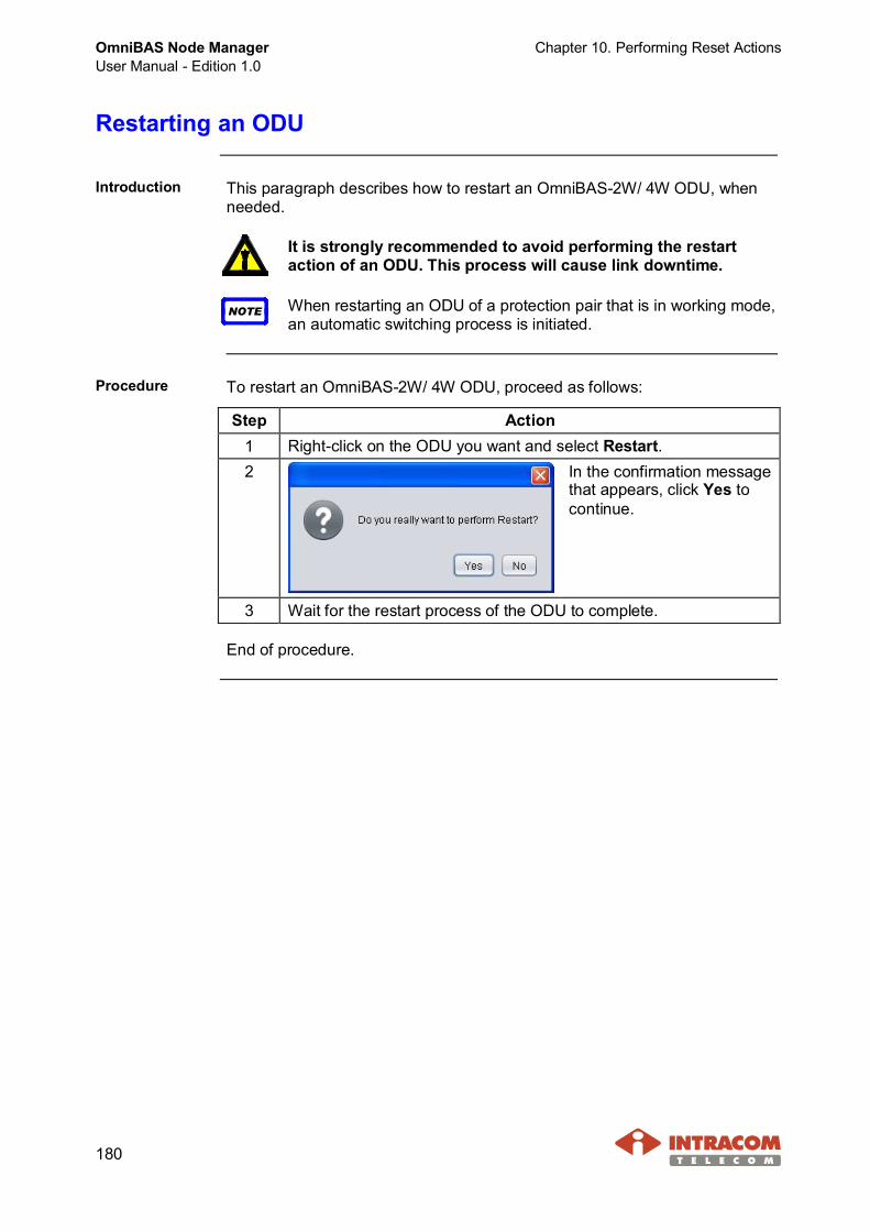
OmniBAS Node ManagerUser Manual - Edition 1.0
Chapter 10. Performing Reset Actions
180
Restarting an ODU
Introduction This paragraph describes how to restart an OmniBAS-2W/ 4W ODU, whenneeded.
It is strongly recommended to avoid performing the restartaction of an ODU. This process will cause link downtime.
NOTE When restarting an ODU of a protection pair that is in working mode,an automatic switching process is initiated.
Procedure To restart an OmniBAS-2W/ 4W ODU, proceed as follows:
Step Action1 Right-click on the ODU you want and select Restart.2 In the confirmation message
that appears, click Yes tocontinue.
3 Wait for the restart process of the ODU to complete.
End of procedure.
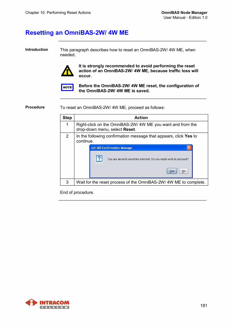
Chapter 10. Performing Reset Actions OmniBAS Node ManagerUser Manual - Edition 1.0
181
Resetting an OmniBAS-2W/ 4W ME
Introduction This paragraph describes how to reset an OmniBAS-2W/ 4W ME, whenneeded.
It is strongly recommended to avoid performing the resetaction of an OmniBAS-2W/ 4W ME, because traffic loss willoccur.
NOTE Before the OmniBAS-2W/ 4W ME reset, the configuration ofthe OmniBAS-2W/ 4W ME is saved.
Procedure To reset an OmniBAS-2W/ 4W ME, proceed as follows:
Step Action1 Right-click on the OmniBAS-2W/ 4W ME you want and from the
drop-down menu, select Reset.2 In the following confirmation message that appears, click Yes to
continue.
3 Wait for the reset process of the OmniBAS-2W/ 4W ME to complete.
End of procedure.
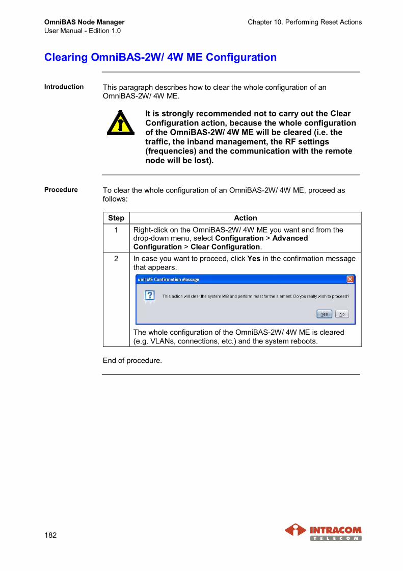
OmniBAS Node ManagerUser Manual - Edition 1.0
Chapter 10. Performing Reset Actions
182
Clearing OmniBAS-2W/ 4W ME Configuration
Introduction This paragraph describes how to clear the whole configuration of anOmniBAS-2W/ 4W ME.
It is strongly recommended not to carry out the ClearConfiguration action, because the whole configurationof the OmniBAS-2W/ 4W ME will be cleared (i.e. thetraffic, the inband management, the RF settings(frequencies) and the communication with the remotenode will be lost).
Procedure To clear the whole configuration of an OmniBAS-2W/ 4W ME, proceed asfollows:
Step Action1 Right-click on the OmniBAS-2W/ 4W ME you want and from the
drop-down menu, select Configuration > AdvancedConfiguration > Clear Configuration.
2 In case you want to proceed, click Yes in the confirmation messagethat appears.
The whole configuration of the OmniBAS-2W/ 4W ME is cleared(e.g. VLANs, connections, etc.) and the system reboots.
End of procedure.

Chapter 10. Performing Reset Actions OmniBAS Node ManagerUser Manual - Edition 1.0
183
Unlocking Filesystem
Introduction This paragraph describes how to unlock the filesystem of an OmniBAS-2W/ 4WME. This action is performed for troubleshooting purposes, when the filesystemof the ME has been locked (and a corresponding message (“Failed” - LockedME) is displayed).The ME lock can be caused by an error during a backup, restore, upgrading,etc. processes.
Procedure To unlock the filesystem of an OmniBAS-2W/ 4W ME, proceed as follows:
Step Action1 Right-click on the OmniBAS-2W/ 4W ME you want and from the
drop-down menu, select Configuration > AdvancedConfiguration > Unlock Filesystem.
2 In the following confirmation message that appears, click Yes.
End of procedure.
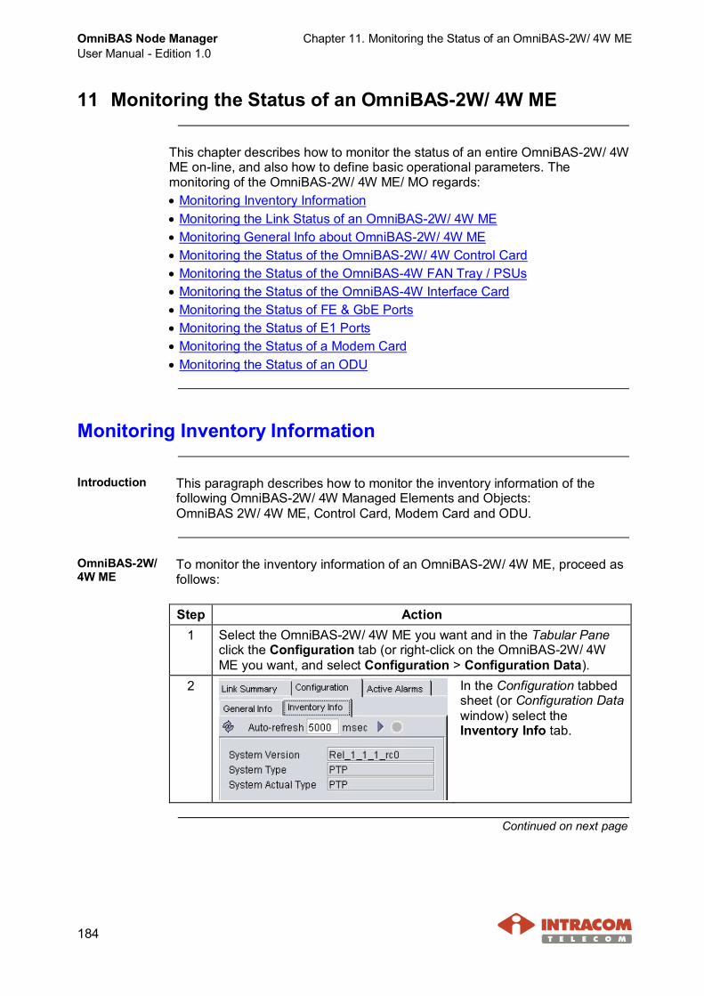
OmniBAS Node ManagerUser Manual - Edition 1.0
Chapter 11. Monitoring the Status of an OmniBAS-2W/ 4W ME
184
11 Monitoring the Status of an OmniBAS-2W/ 4W ME
This chapter describes how to monitor the status of an entire OmniBAS-2W/ 4WME on-line, and also how to define basic operational parameters. Themonitoring of the OmniBAS-2W/ 4W ME/ MO regards:· Monitoring Inventory Information· Monitoring the Link Status of an OmniBAS-2W/ 4W ME· Monitoring General Info about OmniBAS-2W/ 4W ME· Monitoring the Status of the OmniBAS-2W/ 4W Control Card· Monitoring the Status of the OmniBAS-4W FAN Tray / PSUs· Monitoring the Status of the OmniBAS-4W Interface Card· Monitoring the Status of FE & GbE Ports· Monitoring the Status of E1 Ports· Monitoring the Status of a Modem Card· Monitoring the Status of an ODU
Monitoring Inventory Information
Introduction This paragraph describes how to monitor the inventory information of thefollowing OmniBAS-2W/ 4W Managed Elements and Objects:OmniBAS 2W/ 4W ME, Control Card, Modem Card and ODU.
OmniBAS-2W/4W ME
To monitor the inventory information of an OmniBAS-2W/ 4W ME, proceed asfollows:
Step Action1 Select the OmniBAS-2W/ 4W ME you want and in the Tabular Pane
click the Configuration tab (or right-click on the OmniBAS-2W/ 4WME you want, and select Configuration > Configuration Data).
2 In the Configuration tabbedsheet (or Configuration Datawindow) select theInventory Info tab.
Continued on next page
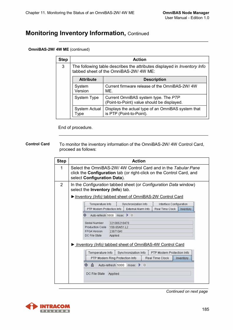
Chapter 11. Monitoring the Status of an OmniBAS-2W/ 4W ME OmniBAS Node ManagerUser Manual - Edition 1.0
185
Monitoring Inventory Information, Continued
OmniBAS-2W/ 4W ME (continued)
Step Action3 The following table describes the attributes displayed in Inventory Info
tabbed sheet of the OmniBAS-2W/ 4W ME:
Attribute DescriptionSystemVersion
Current firmware release of the OmniBAS-2W/ 4WME.
System Type Current OmniBAS system type. The PTP(Point-to-Point) value should be displayed.
System ActualType
Displays the actual type of an OmniBAS system thatis PTP (Point-to-Point).
End of procedure.
Control Card To monitor the inventory information of the OmniBAS-2W/ 4W Control Card,proceed as follows:
Step Action1 Select the OmniBAS-2W/ 4W Control Card and in the Tabular Pane
click the Configuration tab (or right-click on the Control Card, andselect Configuration Data).
2 In the Configuration tabbed sheet (or Configuration Data window)select the Inventory (Info) tab.►Inventory (Info) tabbed sheet of OmniBAS-2W Control Card
► Inventory (Info) tabbed sheet of OmniBAS-4W Control Card
Continued on next page
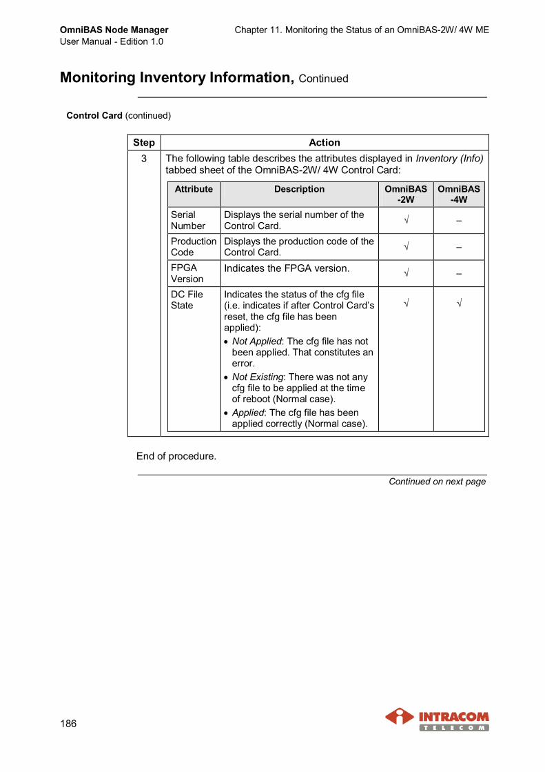
OmniBAS Node ManagerUser Manual - Edition 1.0
Chapter 11. Monitoring the Status of an OmniBAS-2W/ 4W ME
186
Monitoring Inventory Information, Continued
Control Card (continued)
Step Action3 The following table describes the attributes displayed in Inventory (Info)
tabbed sheet of the OmniBAS-2W/ 4W Control Card:
Attribute Description OmniBAS-2W
OmniBAS-4W
SerialNumber
Displays the serial number of theControl Card. √ –
ProductionCode
Displays the production code of theControl Card. √ –
FPGAVersion
Indicates the FPGA version. √ –
DC FileState
Indicates the status of the cfg file(i.e. indicates if after Control Card’sreset, the cfg file has beenapplied):· Not Applied: The cfg file has not
been applied. That constitutes anerror.
· Not Existing: There was not anycfg file to be applied at the timeof reboot (Normal case).
· Applied: The cfg file has beenapplied correctly (Normal case).
√ √
End of procedure.
Continued on next page
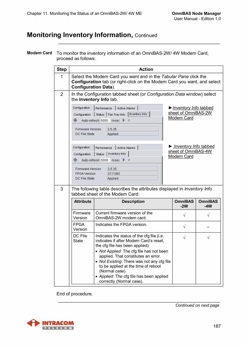
Chapter 11. Monitoring the Status of an OmniBAS-2W/ 4W ME OmniBAS Node ManagerUser Manual - Edition 1.0
187
Monitoring Inventory Information, Continued
Modem Card To monitor the inventory information of an OmniBAS-2W/ 4W Modem Card,proceed as follows:
Step Action1 Select the Modem Card you want and in the Tabular Pane click the
Configuration tab (or right-click on the Modem Card you want, and selectConfiguration Data).
2 In the Configuration tabbed sheet (or Configuration Data window) selectthe Inventory Info tab.
►Inventory Info tabbedsheet of OmniBAS-2WModem Card
► Inventory Info tabbedsheet of OmniBAS-4WModem Card
3 The following table describes the attributes displayed in Inventory Infotabbed sheet of the Modem Card:
Attribute Description OmniBAS-2W
OmniBAS-4W
FirmwareVersion
Current firmware version of theOmniBAS-2W modem card. √ √
FPGAVersion
Indicates the FPGA version. √ –
DC FileState
Indicates the status of the cfg file (i.e.indicates if after Modem Card’s reset,the cfg file has been applied):· Not Applied: The cfg file has not been
applied. That constitutes an error.· Not Existing: There was not any cfg file
to be applied at the time of reboot(Normal case).
· Applied: The cfg file has been appliedcorrectly (Normal case).
√ √
End of procedure.
Continued on next page
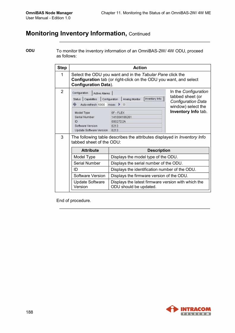
OmniBAS Node ManagerUser Manual - Edition 1.0
Chapter 11. Monitoring the Status of an OmniBAS-2W/ 4W ME
188
Monitoring Inventory Information, Continued
ODU To monitor the inventory information of an OmniBAS-2W/ 4W ODU, proceedas follows:
Step Action1 Select the ODU you want and in the Tabular Pane click the
Configuration tab (or right-click on the ODU you want, and selectConfiguration Data).
2 In the Configurationtabbed sheet (orConfiguration Datawindow) select theInventory Info tab.
3 The following table describes the attributes displayed in Inventory Infotabbed sheet of the ODU:
Attribute DescriptionModel Type Displays the model type of the ODU.Serial Number Displays the serial number of the ODU.ID Displays the identification number of the ODU.Software Version Displays the firmware version of the ODU.Update SoftwareVersion
Displays the latest firmware version with which theODU should be updated.
End of procedure.
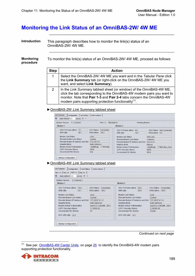
Chapter 11. Monitoring the Status of an OmniBAS-2W/ 4W ME OmniBAS Node ManagerUser Manual - Edition 1.0
189
Monitoring the Link Status of an OmniBAS-2W/ 4W ME
Introduction This paragraph describes how to monitor the link(s) status of anOmniBAS-2W/ 4W ME.
Monitoringprocedure
To monitor the link(s) status of an OmniBAS-2W/ 4W ME, proceed as follows:
Step Action1 Select the OmniBAS-2W/ 4W ME you want and in the Tabular Pane click
the Link Summary tab (or right-click on the OmniBAS-2W/ 4W ME youwant, and select Link Summary).
2 In the Link Summary tabbed sheet (or window) of the OmniBAS-4W ME,click the tab corresponding to the OmniBAS-4W modem pairs you want tomonitor. Note that Pair 1-3 and Pair 2-4 tabs concern the OmniBAS-4Wmodem pairs supporting protection functionality(1).
►OmniBAS-2W Link Summary tabbed sheet
►OmniBAS-4W Link Summary tabbed sheet
Continued on next page
(1) See par. OmniBAS-4W Cards/ Units, on page 25 to identify the OmniBAS-4W modem pairssupporting protection functionality.

OmniBAS Node ManagerUser Manual - Edition 1.0
Chapter 11. Monitoring the Status of an OmniBAS-2W/ 4W ME
190
Monitoring the Link Status of an OmniBAS-2W/ 4W ME,Continued
Monitoring procedure (continued)
Step Action3 The link status information concerning the corresponding
OmniBAS-2W/ 4W Modem Cards appears. Find in the following par.Attributes description the detail description of the attributes displayedin the Link Summary tabbed sheets.
End of procedure.
Attributesdescription
The following table describes the attributes displayed in the Link Summarytabbed sheet (or Link Summary window) for each OmniBAS-2W/ 4W modem:
Attribute DescriptionODU Tx Power Indicates the current power transmitted from the ODU (in dBm)
that is connected on the specific modem.ODU Status Indicates the operation status of the ODU (Connected or Not
Connected) corresponding to the specific modem.SNR Indicates the Signal-to-Noise Ratio value (in dB) for the specific
modem.RSSI Indicates the current signal strength of the ODU connected on
the selected modem (in dBm).Modem LinkStatus
Indicates the Rx link status of the selected modem:· Lock – Rx link communication with the corresponding
remote modem is Ok (Rx link is locked and it is Ok).· Wait Lock – Rx link is not locked yet.· Failed – Modem failure. In this case the Modem Link Failed
alarm (with ID = 14041 for OmniBAS-2W andID = 6041 for OmniBAS-4W) will be issued.
Remote ModemLink Status
Indicates the Rx link status of the remote modem:· Locked – Remote modem reception is Ok.· Unlocked – Link communication is failed. Remote modem
reception is not locked.· Failed – Link communication is failed. Remote modem
status cannot be retrieved. In this case the Remote ModemLink Failed alarm (with ID = 14042 for OmniBAS-2W andID = 6042 for OmniBAS-4W) will be issued.
Remote ModemIP Address andSlot
Indicates the IP address and the slot position of the remotemodem. The IP address and slot of the remote modem aredisplayed separated by a “/” (slash) symbol.
Continued on next page

Chapter 11. Monitoring the Status of an OmniBAS-2W/ 4W ME OmniBAS Node ManagerUser Manual - Edition 1.0
191
Monitoring the Link Status of an OmniBAS-2W/ 4W ME,Continued
Attributes description (continued)
Attribute DescriptionAdaptive Mode Indicates the current adaptive mode used by the selected
modem.· Manual – No ACM/ ATPC feature is enabled for the
selected modem.· Auto/ Manual Power – ACM/ ATPC feature is enabled for
the selected modem. Regarding the ATPC feature, themanual Tx power level has been set.
· Auto/ Optimum – ACM/ ATPC feature is enabled for theselected modem. Regarding the ATPC feature, theoptimum Tx power level has been set.
· Auto/ Max Power – ACM/ ATPC feature is enabled for theselected modem. Regarding the ATPC feature, themaximum Tx power level has been set.
Modem ActualTx Modulation
Indicates the actual modulation mode used by the specificmodem.
LDPC DecodesStress
Indicates the Low-Density Parity Check (LDPC) decoderstress.
UncorrectedFEC
Indicates the total number of uncorrected frames inserted theFEC mechanism.

OmniBAS Node ManagerUser Manual - Edition 1.0
Chapter 11. Monitoring the Status of an OmniBAS-2W/ 4W ME
192
Monitoring General Info about OmniBAS-2W/ 4W ME
Introduction This paragraph describes how to view and define general information aboutan OmniBAS-2W/ 4W ME.
Monitoringprocedure
To view and define general information about an OmniBAS-2W/ 4W ME,proceed as follows:
Step Action1 Select the OmniBAS-2W/ 4W ME you want and in the Tabular Pane
click the Configuration tab (or right-click on the OmniBAS-2W/ 4W MEyou want, and select Configuration > Configuration Data).
2 In the Configuration tabbed sheet (or Configuration Data window) thatappears, the General Info tab is displayed - if not, select it:
The General Info tabbed sheet displays general information about theselected OmniBAS-2W/ 4W ME:· System Description: Name of connected system (OmniBAS-2W/ 4W)· System Up Time: Total time that the system is up (since system last
reset).· IP Address: IP address of the selected system.
3 Also, in the General Info tabbed sheet you can enter any of thefollowing information about the OmniBAS-2W/ 4W ME:· A label for the selected system (in the Name (1) text box)· Responsible person of the system (in the Contact (1) text box)· System location (in the Location (1) text box)
When you complete, click the button, to apply the changes.
End of procedure.
(1) Alphanumeric string of up to 32 characters.
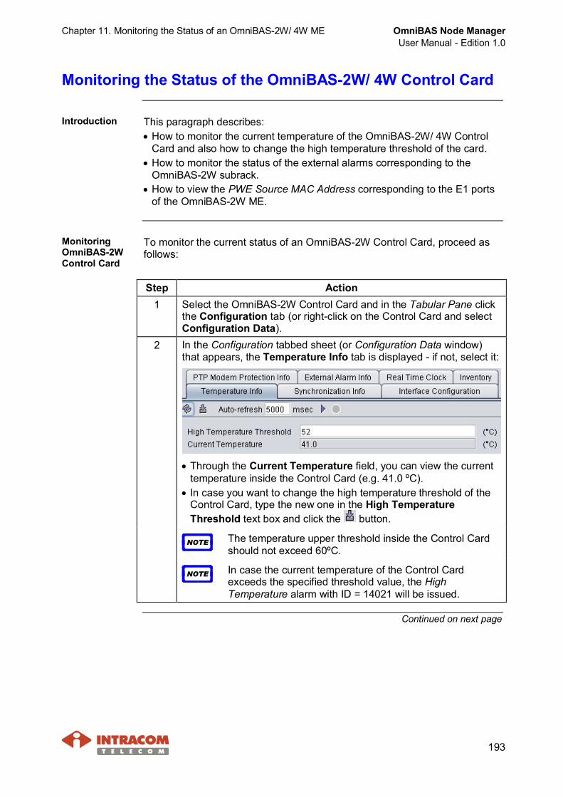
Chapter 11. Monitoring the Status of an OmniBAS-2W/ 4W ME OmniBAS Node ManagerUser Manual - Edition 1.0
193
Monitoring the Status of the OmniBAS-2W/ 4W Control Card
Introduction This paragraph describes:· How to monitor the current temperature of the OmniBAS-2W/ 4W Control
Card and also how to change the high temperature threshold of the card.· How to monitor the status of the external alarms corresponding to the
OmniBAS-2W subrack.· How to view the PWE Source MAC Address corresponding to the E1 ports
of the OmniBAS-2W ME.
MonitoringOmniBAS-2WControl Card
To monitor the current status of an OmniBAS-2W Control Card, proceed asfollows:
Step Action1 Select the OmniBAS-2W Control Card and in the Tabular Pane click
the Configuration tab (or right-click on the Control Card and selectConfiguration Data).
2 In the Configuration tabbed sheet (or Configuration Data window)that appears, the Temperature Info tab is displayed - if not, select it:
· Through the Current Temperature field, you can view the currenttemperature inside the Control Card (e.g. 41.0 ºC).
· In case you want to change the high temperature threshold of theControl Card, type the new one in the High TemperatureThreshold text box and click the button.
NOTE The temperature upper threshold inside the Control Cardshould not exceed 60ºC.
NOTE In case the current temperature of the Control Cardexceeds the specified threshold value, the HighTemperature alarm with ID = 14021 will be issued.
Continued on next page
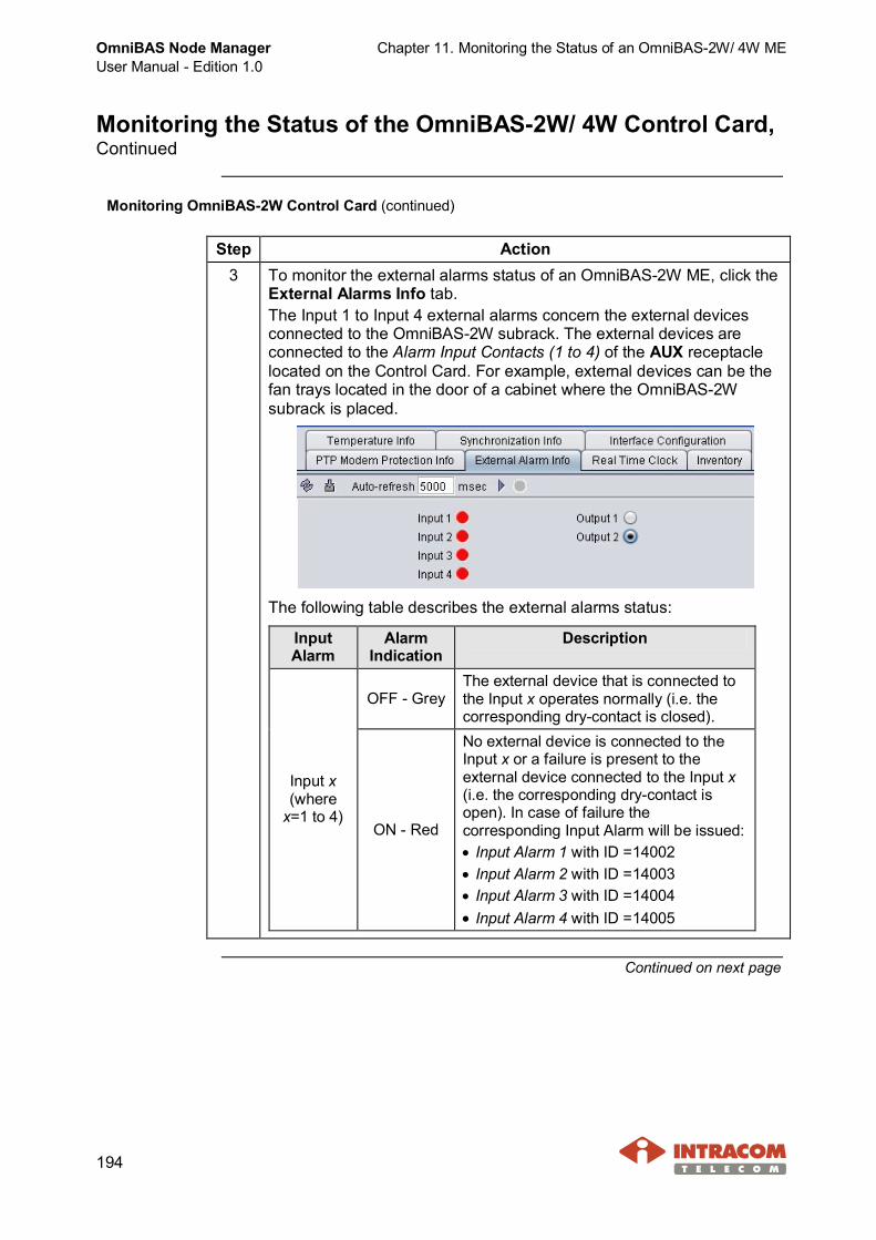
OmniBAS Node ManagerUser Manual - Edition 1.0
Chapter 11. Monitoring the Status of an OmniBAS-2W/ 4W ME
194
Monitoring the Status of the OmniBAS-2W/ 4W Control Card,Continued
Monitoring OmniBAS-2W Control Card (continued)
Step Action3 To monitor the external alarms status of an OmniBAS-2W ME, click the
External Alarms Info tab.The Input 1 to Input 4 external alarms concern the external devicesconnected to the OmniBAS-2W subrack. The external devices areconnected to the Alarm Input Contacts (1 to 4) of the AUX receptaclelocated on the Control Card. For example, external devices can be thefan trays located in the door of a cabinet where the OmniBAS-2Wsubrack is placed.
The following table describes the external alarms status:
InputAlarm
AlarmIndication
Description
OFF - GreyThe external device that is connected tothe Input x operates normally (i.e. thecorresponding dry-contact is closed).
Input x(where
x=1 to 4)ON - Red
No external device is connected to theInput x or a failure is present to theexternal device connected to the Input x(i.e. the corresponding dry-contact isopen). In case of failure thecorresponding Input Alarm will be issued:· Input Alarm 1 with ID =14002· Input Alarm 2 with ID =14003· Input Alarm 3 with ID =14004· Input Alarm 4 with ID =14005
Continued on next page
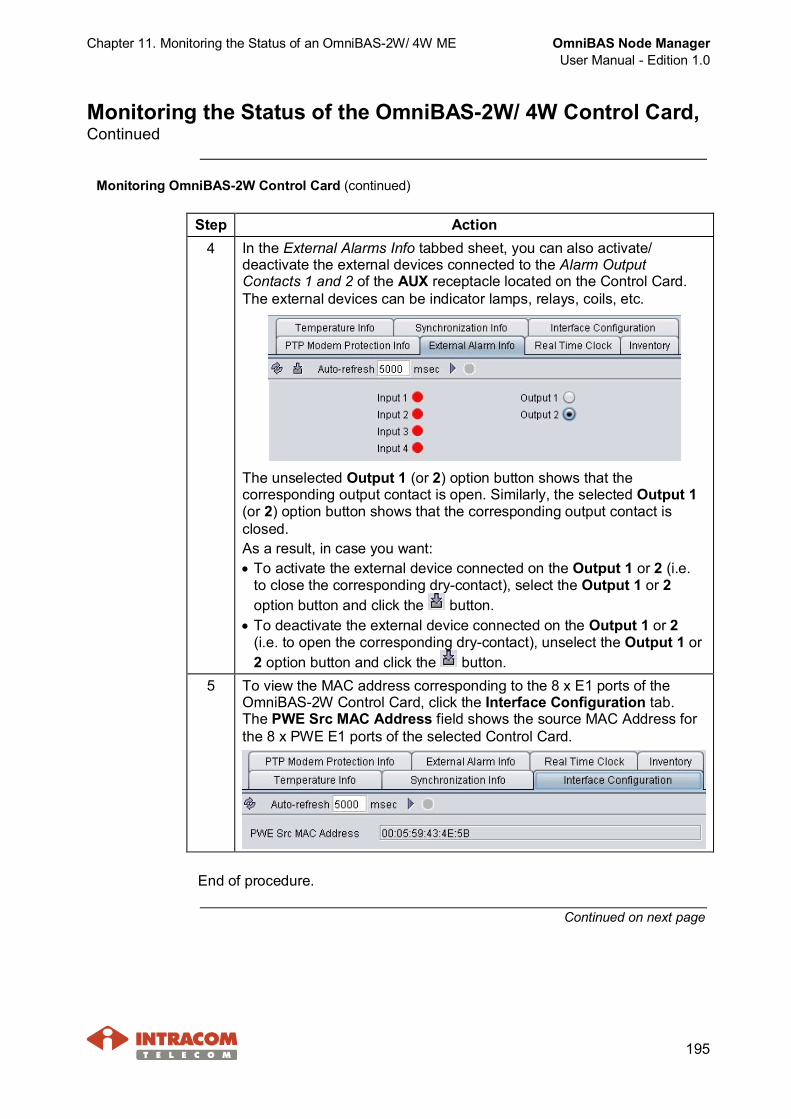
Chapter 11. Monitoring the Status of an OmniBAS-2W/ 4W ME OmniBAS Node ManagerUser Manual - Edition 1.0
195
Monitoring the Status of the OmniBAS-2W/ 4W Control Card,Continued
Monitoring OmniBAS-2W Control Card (continued)
Step Action4 In the External Alarms Info tabbed sheet, you can also activate/
deactivate the external devices connected to the Alarm OutputContacts 1 and 2 of the AUX receptacle located on the Control Card.The external devices can be indicator lamps, relays, coils, etc.
The unselected Output 1 (or 2) option button shows that thecorresponding output contact is open. Similarly, the selected Output 1(or 2) option button shows that the corresponding output contact isclosed.As a result, in case you want:· To activate the external device connected on the Output 1 or 2 (i.e.
to close the corresponding dry-contact), select the Output 1 or 2option button and click the button.
· To deactivate the external device connected on the Output 1 or 2(i.e. to open the corresponding dry-contact), unselect the Output 1 or2 option button and click the button.
5 To view the MAC address corresponding to the 8 x E1 ports of theOmniBAS-2W Control Card, click the Interface Configuration tab.The PWE Src MAC Address field shows the source MAC Address forthe 8 x PWE E1 ports of the selected Control Card.
End of procedure.
Continued on next page
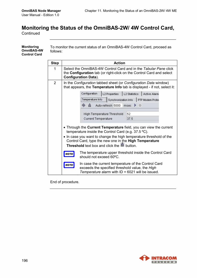
OmniBAS Node ManagerUser Manual - Edition 1.0
Chapter 11. Monitoring the Status of an OmniBAS-2W/ 4W ME
196
Monitoring the Status of the OmniBAS-2W/ 4W Control Card,Continued
MonitoringOmniBAS-4WControl Card
To monitor the current status of an OmniBAS-4W Control Card, proceed asfollows:
Step Action1 Select the OmniBAS-4W Control Card and in the Tabular Pane click
the Configuration tab (or right-click on the Control Card and selectConfiguration Data).
2 In the Configuration tabbed sheet (or Configuration Data window)that appears, the Temperature Info tab is displayed - if not, select it:
· Through the Current Temperature field, you can view the currenttemperature inside the Control Card (e.g. 37.5 ºC).
· In case you want to change the high temperature threshold of theControl Card, type the new one in the High TemperatureThreshold text box and click the button.
NOTE The temperature upper threshold inside the Control Cardshould not exceed 60ºC.
NOTE In case the current temperature of the Control Cardexceeds the specified threshold value, the HighTemperature alarm with ID = 6021 will be issued.
End of procedure.
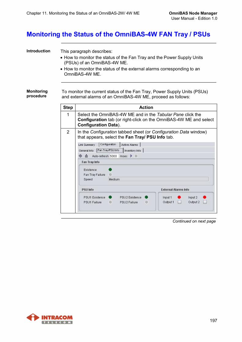
Chapter 11. Monitoring the Status of an OmniBAS-2W/ 4W ME OmniBAS Node ManagerUser Manual - Edition 1.0
197
Monitoring the Status of the OmniBAS-4W FAN Tray / PSUs
Introduction This paragraph describes:· How to monitor the status of the Fan Tray and the Power Supply Units
(PSUs) of an OmniBAS-4W ME.· How to monitor the status of the external alarms corresponding to an
OmniBAS-4W ME.
Monitoringprocedure
To monitor the current status of the Fan Tray, Power Supply Units (PSUs)and external alarms of an OmniBAS-4W ME, proceed as follows:
Step Action1 Select the OmniBAS-4W ME and in the Tabular Pane click the
Configuration tab (or right-click on the OmniBAS-4W ME and selectConfiguration Data).
2 In the Configuration tabbed sheet (or Configuration Data window)that appears, select the Fan Tray/ PSU Info tab.
Continued on next page
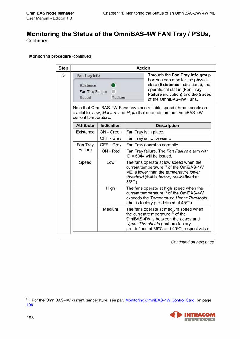
OmniBAS Node ManagerUser Manual - Edition 1.0
Chapter 11. Monitoring the Status of an OmniBAS-2W/ 4W ME
198
Monitoring the Status of the OmniBAS-4W FAN Tray / PSUs,Continued
Monitoring procedure (continued)
Step Action3 Through the Fan Tray Info group
box you can monitor the physicalstate (Existence indications), theoperational status (Fan TrayFailure indication) and the Speedof the OmniBAS-4W Fans.
Note that OmniBAS-4W Fans have controllable speed (three speeds areavailable, Low, Medium and High) that depends on the OmniBAS-4Wcurrent temperature.
Attribute Indication DescriptionON - Green Fan Tray is in place.ExistenceOFF - Grey Fan Tray is not present.OFF - Grey Fan Tray operates normally.Fan Tray
Failure ON - Red Fan Tray failure. The Fan Failure alarm withID = 6044 will be issued.
Low The fans operate at low speed when thecurrent temperature(1) of the OmiBAS-4WME is lower than the temperature lowerthreshold (that is factory pre-defined at35ºC).
High The fans operate at high speed when thecurrent temperature(1) of the OmiBAS-4Wexceeds the Temperature Upper Threshold(that is factory pre-defined at 45ºC).
Speed
Medium The fans operate at medium speed whenthe current temperature(1) of theOmiBAS-4W is between the Lower andUpper Thresholds (that are factorypre-defined at 35ºC and 45ºC, respectively).
Continued on next page
(1) For the OmniBAS-4W current temperature, see par. Monitoring OmniBAS-4W Control Card, on page196.
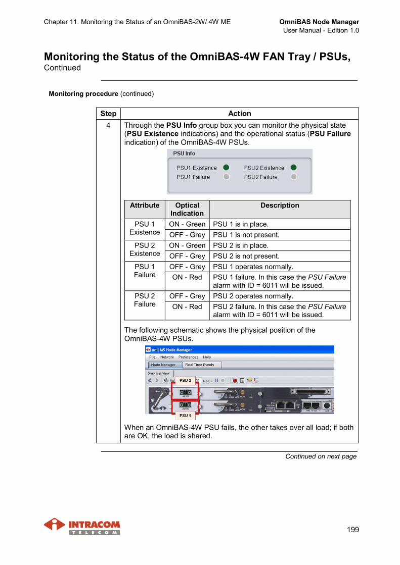
Chapter 11. Monitoring the Status of an OmniBAS-2W/ 4W ME OmniBAS Node ManagerUser Manual - Edition 1.0
199
Monitoring the Status of the OmniBAS-4W FAN Tray / PSUs,Continued
Monitoring procedure (continued)
Step Action4 Through the PSU Info group box you can monitor the physical state
(PSU Existence indications) and the operational status (PSU Failureindication) of the OmniBAS-4W PSUs.
Attribute OpticalIndication
Description
ON - Green PSU 1 is in place.PSU 1Existence OFF - Grey PSU 1 is not present.
ON - Green PSU 2 is in place.PSU 2Existence OFF - Grey PSU 2 is not present.
OFF - Grey PSU 1 operates normally.PSU 1Failure ON - Red PSU 1 failure. In this case the PSU Failure
alarm with ID = 6011 will be issued.OFF - Grey PSU 2 operates normally.PSU 2
Failure ON - Red PSU 2 failure. In this case the PSU Failurealarm with ID = 6011 will be issued.
The following schematic shows the physical position of theOmniBAS-4W PSUs.
When an OmniBAS-4W PSU fails, the other takes over all load; if bothare OK, the load is shared.
Continued on next page

OmniBAS Node ManagerUser Manual - Edition 1.0
Chapter 11. Monitoring the Status of an OmniBAS-2W/ 4W ME
200
Monitoring the Status of the OmniBAS-4W FAN Tray / PSUs,Continued
Monitoring procedure (continued)
Step Action5 Through the External Alarms Info group box you can monitor the
external alarms status of an OmniBAS-4W ME.The Input 1 and Input 2 external alarms concern the external devicesconnected to the OmniBAS-4W subrack. The external devices areconnected to the Alarm Input Contacts (1 to 2) of the AUX receptaclelocated on the Control Card. For example, external devices can bethe fan trays located in the door of a cabinet where the OmniBAS-4Wsubrack is placed.
The following table describes the external alarms (Input 1 andInput 2) possible states:
AlarmIndication
Description
OFF - GreyThe external device that is connected to the Input 1 or 2operates normally (i.e. the corresponding dry-contact isclosed).
ON - Red
Probable Cause:· No external device is connected to the Input 1 or
Input 2.· Failure is present to the external device connected to
the Input 1 or Input 2 (i.e. the correspondingdry-contact is open). In case of failure, thecorresponding alarms will be issued:- Input Alarm 1 with ID =6002- Input Alarm 2 with ID =6003
Continued on next page

Chapter 11. Monitoring the Status of an OmniBAS-2W/ 4W ME OmniBAS Node ManagerUser Manual - Edition 1.0
201
Monitoring the Status of the OmniBAS-4W FAN Tray / PSUs,Continued
Monitoring procedure (continued)
Step Action6 Through the External Alarms Info group box, you can also activate/
deactivate the external devices connected to the Alarm OutputContacts 1 and 2 of the AUX receptacle located on the Control Card.The external devices can be indicator lamps, relays, coils, etc.
The unselected Output 1 (or 2) check box shows that thecorresponding output contact is open. Similarly, the selected Output 1(or 2) check box shows that the corresponding output contact isclosed.As a result, in case you want:· To activate the external device connected on the Output 1 or 2 (i.e.
to close the corresponding dry-contact), select the Output 1 or 2check box and click the button.
· To deactivate the external device connected on the Output 1 or 2(i.e. to open the corresponding dry-contact), unselect the Output 1or 2 check box and click the button.
End of procedure.
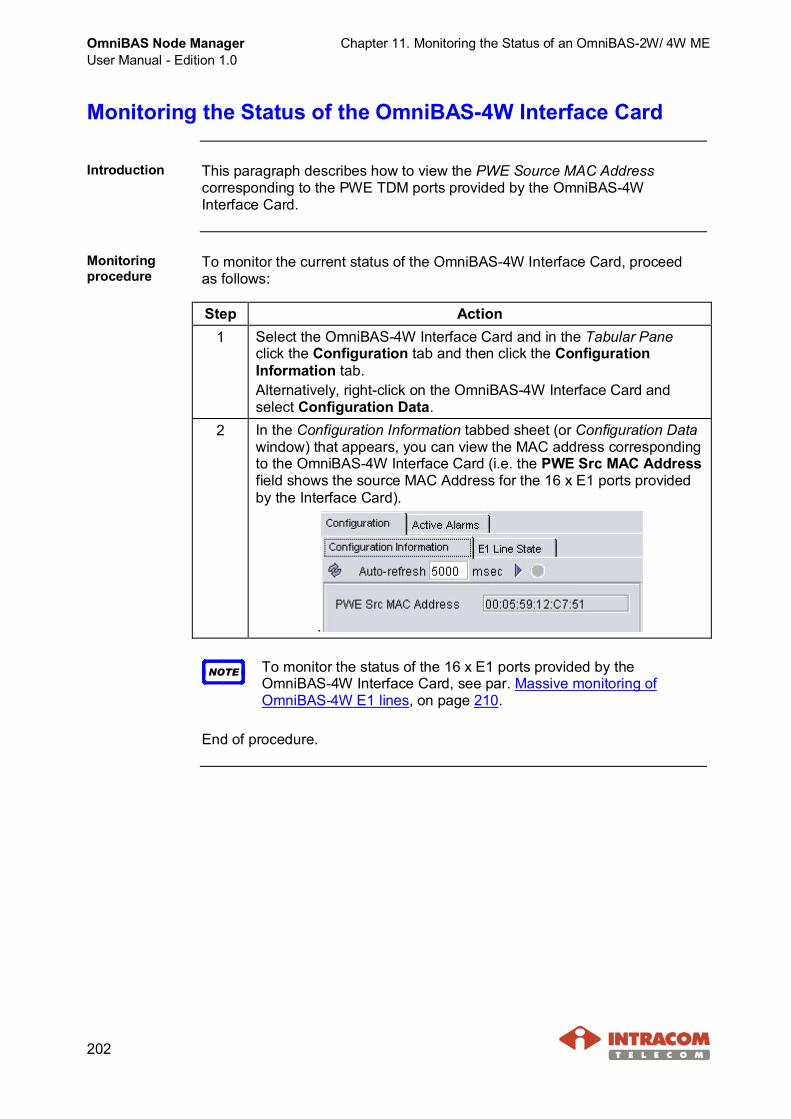
OmniBAS Node ManagerUser Manual - Edition 1.0
Chapter 11. Monitoring the Status of an OmniBAS-2W/ 4W ME
202
Monitoring the Status of the OmniBAS-4W Interface Card
Introduction This paragraph describes how to view the PWE Source MAC Addresscorresponding to the PWE TDM ports provided by the OmniBAS-4WInterface Card.
Monitoringprocedure
To monitor the current status of the OmniBAS-4W Interface Card, proceedas follows:
Step Action1 Select the OmniBAS-4W Interface Card and in the Tabular Pane
click the Configuration tab and then click the ConfigurationInformation tab.Alternatively, right-click on the OmniBAS-4W Interface Card andselect Configuration Data.
2 In the Configuration Information tabbed sheet (or Configuration Datawindow) that appears, you can view the MAC address correspondingto the OmniBAS-4W Interface Card (i.e. the PWE Src MAC Addressfield shows the source MAC Address for the 16 x E1 ports providedby the Interface Card).
.
NOTE To monitor the status of the 16 x E1 ports provided by theOmniBAS-4W Interface Card, see par. Massive monitoring ofOmniBAS-4W E1 lines, on page 210.
End of procedure.

Chapter 11. Monitoring the Status of an OmniBAS-2W/ 4W ME OmniBAS Node ManagerUser Manual - Edition 1.0
203
Monitoring the Status of FE & GbE Ports
Introduction This paragraph describes how to monitor the status of the Fast Ethernet(FE) and Gigabit Ethernet (GbE) ports of an OmniBAS-2W ME and theGigabit Ethernet (GbE) ports of an OmniBAS-4W ME.· Regarding OmniBAS-2W ME, OmniBAS Node Manager detects the
physical type of the selected OmniBAS-2W GbE port (electrical or optical).Hence, when you select the Configuration tab in the Tabular Pane, thecorresponding Electrical or Optical tabbed sheet is activated.
· Regarding OmniBAS-4W ME, two versions of Control Card are available,one equipped with electrical GbE ports and one with optical GbE ports.Depending on the Control Card’s version that are currently used by theOmniBAS-4W system, the corresponding information appears in theConfiguration tabbed sheet of the selected GbE port.
Continued on next page
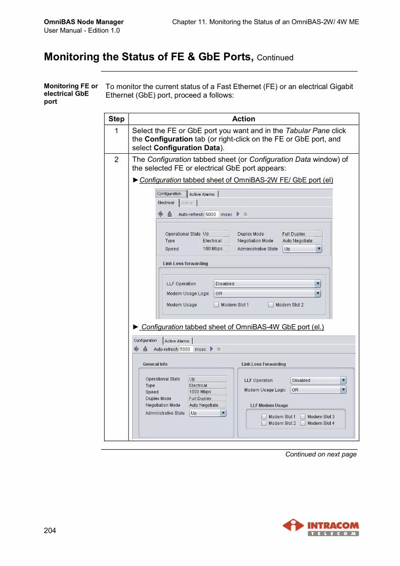
OmniBAS Node ManagerUser Manual - Edition 1.0
Chapter 11. Monitoring the Status of an OmniBAS-2W/ 4W ME
204
Monitoring the Status of FE & GbE Ports, Continued
Monitoring FE orelectrical GbEport
To monitor the current status of a Fast Ethernet (FE) or an electrical GigabitEthernet (GbE) port, proceed a follows:
Step Action1 Select the FE or GbE port you want and in the Tabular Pane click
the Configuration tab (or right-click on the FE or GbE port, andselect Configuration Data).
2 The Configuration tabbed sheet (or Configuration Data window) ofthe selected FE or electrical GbE port appears:►Configuration tabbed sheet of OmniBAS-2W FE/ GbE port (el)
► Configuration tabbed sheet of OmniBAS-4W GbE port (el.)
Continued on next page

Chapter 11. Monitoring the Status of an OmniBAS-2W/ 4W ME OmniBAS Node ManagerUser Manual - Edition 1.0
205
Monitoring the Status of FE & GbE Ports, Continued
Monitoring FE or electrical GbE port (continued)
Step Action3 You can check the current status of the selected FE or electrical GbE
port through the following attributes:
Attribute DescriptionOperationalState
Indicates the current operating status of the selected FEor GbE port, i.e. if the link associated with this port is Upor Down.When the Ethernet link is Up, the (green) state iconappears on the corresponding FE or GbE port. When theEthernet link is Down, no state icon appears.
Type Indicates the type of the FE or GbE port (i.e. Electrical).When the corresponding GbE link is down, the Unknownstatus is displayed.
Speed Indicates the throughput capacity on the selected port:· 10 Mbps, 100 Mbps or 1000 Mbps, in case of GbE port· 10 Mbps or 100 Mbps in case of FE port
Duplex Mode Indicates the physical operation mode (Full Duplex orHalf Duplex) of the selected FE or GbE port.
NegotiationMode
Indicates the Auto Negotiation(1) status of the selectedFE or GbE port.
AdministrativeState
Indicates if the administrative state of the selected FE orGbE port is Up (traffic passes through the selected port)or Down (no traffic passes through the selected port).
End of procedure.
Continued on next page
(1) Auto-negotiation is a mechanism that enables devices with different technologies to exchangeinformation about speed and duplex mode abilities over an Ethernet link.

OmniBAS Node ManagerUser Manual - Edition 1.0
Chapter 11. Monitoring the Status of an OmniBAS-2W/ 4W ME
206
Monitoring the Status of FE & GbE Ports, Continued
Monitoringoptical GbE port
To monitor the current status of an optical Gigabit Ethernet (GbE) port,proceed a follows:
Step Action1 Select the GbE port of the OmniBAS-2W/ 4W ME you want and in
the Tabular Pane click the Configuration tab (or right-click on theGbE port, and select Configuration Data).
2 The Configuration tabbed sheet (or Configuration Data window) ofthe selected optical GbE port appears:►Configuration tabbed sheet of OmniBAS-2W GbE port (opt.)
► Configuration tabbed sheet of OmniBAS-4W GbE port (opt.)
Continued on next page
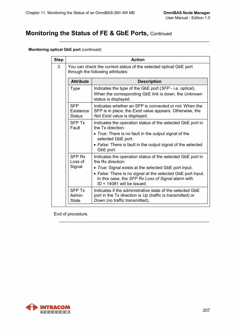
Chapter 11. Monitoring the Status of an OmniBAS-2W/ 4W ME OmniBAS Node ManagerUser Manual - Edition 1.0
207
Monitoring the Status of FE & GbE Ports, Continued
Monitoring optical GbE port (continued)
Step Action3 You can check the current status of the selected optical GbE port
through the following attributes:
Attribute DescriptionType Indicates the type of the GbE port (SFP - i.e. optical).
When the corresponding GbE link is down, the Unknownstatus is displayed.
SFPExistenceStatus
Indicates whether an SFP is connected or not. When theSFP is in place, the Exist value appears. Otherwise, theNot Exist value is displayed.
SFP TxFault
Indicates the operation status of the selected GbE port inthe Tx direction:· True: There is no fault in the output signal of the
selected GbE port.· False: There is fault in the output signal of the selected
GbE port.SFP RxLoss ofSignal
Indicates the operation status of the selected GbE port inthe Rx direction:· True: Signal exists at the selected GbE port input.· False: There is no signal at the selected GbE port input.
In this case, the SFP Rx Loss of Signal alarm withID = 14081 will be issued.
SFP TxAdminState
Indicates if the administrative state of the selected GbEport in the Tx direction is Up (traffic is transmitted) orDown (no traffic transmitted).
End of procedure.
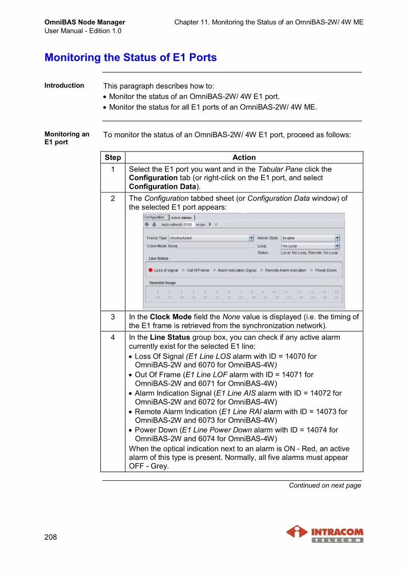
OmniBAS Node ManagerUser Manual - Edition 1.0
Chapter 11. Monitoring the Status of an OmniBAS-2W/ 4W ME
208
Monitoring the Status of E1 Ports
Introduction This paragraph describes how to:· Monitor the status of an OmniBAS-2W/ 4W E1 port.· Monitor the status for all E1 ports of an OmniBAS-2W/ 4W ME.
Monitoring anE1 port
To monitor the status of an OmniBAS-2W/ 4W E1 port, proceed as follows:
Step Action1 Select the E1 port you want and in the Tabular Pane click the
Configuration tab (or right-click on the E1 port, and selectConfiguration Data).
2 The Configuration tabbed sheet (or Configuration Data window) ofthe selected E1 port appears:
3 In the Clock Mode field the None value is displayed (i.e. the timing ofthe E1 frame is retrieved from the synchronization network).
4 In the Line Status group box, you can check if any active alarmcurrently exist for the selected E1 line:· Loss Of Signal (E1 Line LOS alarm with ID = 14070 for
OmniBAS-2W and 6070 for OmniBAS-4W)· Out Of Frame (E1 Line LOF alarm with ID = 14071 for
OmniBAS-2W and 6071 for OmniBAS-4W)· Alarm Indication Signal (E1 Line AIS alarm with ID = 14072 for
OmniBAS-2W and 6072 for OmniBAS-4W)· Remote Alarm Indication (E1 Line RAI alarm with ID = 14073 for
OmniBAS-2W and 6073 for OmniBAS-4W)· Power Down (E1 Line Power Down alarm with ID = 14074 for
OmniBAS-2W and 6074 for OmniBAS-4W)When the optical indication next to an alarm is ON - Red, an activealarm of this type is present. Normally, all five alarms must appearOFF - Grey.
Continued on next page
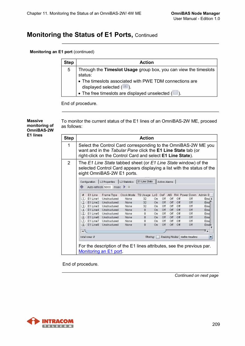
Chapter 11. Monitoring the Status of an OmniBAS-2W/ 4W ME OmniBAS Node ManagerUser Manual - Edition 1.0
209
Monitoring the Status of E1 Ports, Continued
Monitoring an E1 port (continued)
Step Action5 Through the Timeslot Usage group box, you can view the timeslots
status:· The timeslots associated with PWE TDM connections are
displayed selected ( ).· The free timeslots are displayed unselected ( ).
End of procedure.
Massivemonitoring ofOmniBAS-2WE1 lines
To monitor the current status of the E1 lines of an OmniBAS-2W ME, proceedas follows:
Step Action1 Select the Control Card corresponding to the OmniBAS-2W ME you
want and in the Tabular Pane click the E1 Line State tab (orright-click on the Control Card and select E1 Line State).
2 The E1 Line State tabbed sheet (or E1 Line State window) of theselected Control Card appears displaying a list with the status of theeight OmniBAS-2W E1 ports.
For the description of the E1 lines attributes, see the previous par.Monitoring an E1 port.
End of procedure.
Continued on next page
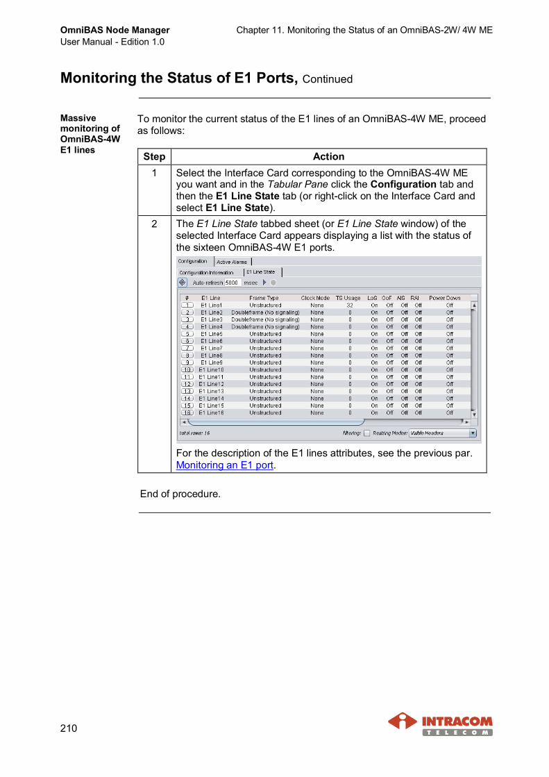
OmniBAS Node ManagerUser Manual - Edition 1.0
Chapter 11. Monitoring the Status of an OmniBAS-2W/ 4W ME
210
Monitoring the Status of E1 Ports, Continued
Massivemonitoring ofOmniBAS-4WE1 lines
To monitor the current status of the E1 lines of an OmniBAS-4W ME, proceedas follows:
Step Action1 Select the Interface Card corresponding to the OmniBAS-4W ME
you want and in the Tabular Pane click the Configuration tab andthen the E1 Line State tab (or right-click on the Interface Card andselect E1 Line State).
2 The E1 Line State tabbed sheet (or E1 Line State window) of theselected Interface Card appears displaying a list with the status ofthe sixteen OmniBAS-4W E1 ports.
For the description of the E1 lines attributes, see the previous par.Monitoring an E1 port.
End of procedure.
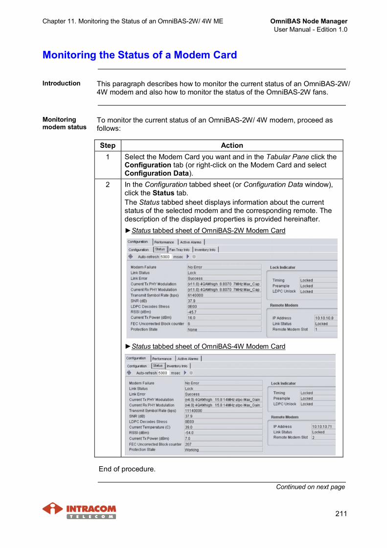
Chapter 11. Monitoring the Status of an OmniBAS-2W/ 4W ME OmniBAS Node ManagerUser Manual - Edition 1.0
211
Monitoring the Status of a Modem Card
Introduction This paragraph describes how to monitor the current status of an OmniBAS-2W/4W modem and also how to monitor the status of the OmniBAS-2W fans.
Monitoringmodem status
To monitor the current status of an OmniBAS-2W/ 4W modem, proceed asfollows:
Step Action1 Select the Modem Card you want and in the Tabular Pane click the
Configuration tab (or right-click on the Modem Card and selectConfiguration Data).
2 In the Configuration tabbed sheet (or Configuration Data window),click the Status tab.The Status tabbed sheet displays information about the currentstatus of the selected modem and the corresponding remote. Thedescription of the displayed properties is provided hereinafter.►Status tabbed sheet of OmniBAS-2W Modem Card
►Status tabbed sheet of OmniBAS-4W Modem Card
End of procedure.
Continued on next page
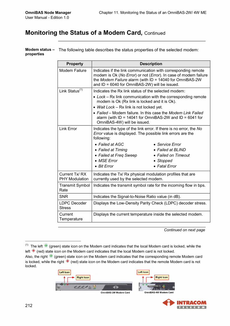
OmniBAS Node ManagerUser Manual - Edition 1.0
Chapter 11. Monitoring the Status of an OmniBAS-2W/ 4W ME
212
Monitoring the Status of a Modem Card, Continued
Modem status –properties
The following table describes the status properties of the selected modem:
Property DescriptionModem Failure Indicates if the link communication with corresponding remote
modem is Ok (No Error) or not (Error). In case of modem failurethe Modem Failure alarm (with ID = 14040 for OmniBAS-2Wand ID = 6040 for OmniBAS-2W) will be issued.
Link Status(1) Indicates the Rx link status of the selected modem:· Lock – Rx link communication with the corresponding remote
modem is Ok (Rx link is locked and it is Ok).· Wait Lock – Rx link is not locked yet.· Failed – Modem failure. In this case the Modem Link Failed
alarm (with ID = 14041 for OmniBAS-2W and ID = 6041 forOmniBAS-4W) will be issued.
Link Error Indicates the type of the link error. If there is no error, the NoError value is displayed. The possible link errors are thefollowing:· Failed at AGC· Failed at Timing· Failed at Freq Sweep· MSE Error· Bit Error
· Service Error· Failed at BLIND· Failed on Timeout· Stopped· Fatal Error
Current Tx/ RXPHY Modulation
Indicates the Tx/ Rx physical modulation profiles that arecurrently used by the selected modem.
Transmit SymbolRate
Indicates the transmit symbol rate for the incoming flow in bps.
SNR Indicates the Signal-to-Noise Ratio value (in dB).LDPC DecoderStress
Displays the Low-Density Parity Check (LDPC) decoder stress.
CurrentTemperature
Displays the current temperature inside the selected modem.
Continued on next page
(1) The left (green) state icon on the Modem card indicates that the local Modem card is locked, while theleft (red) state icon on the Modem card indicates that the local Modem card is not locked.Also, the right (green) state icon on the Modem card indicates that the corresponding remote Modem cardis locked, while the right (red) state icon on the Modem card indicates that the remote Modem card is notlocked.
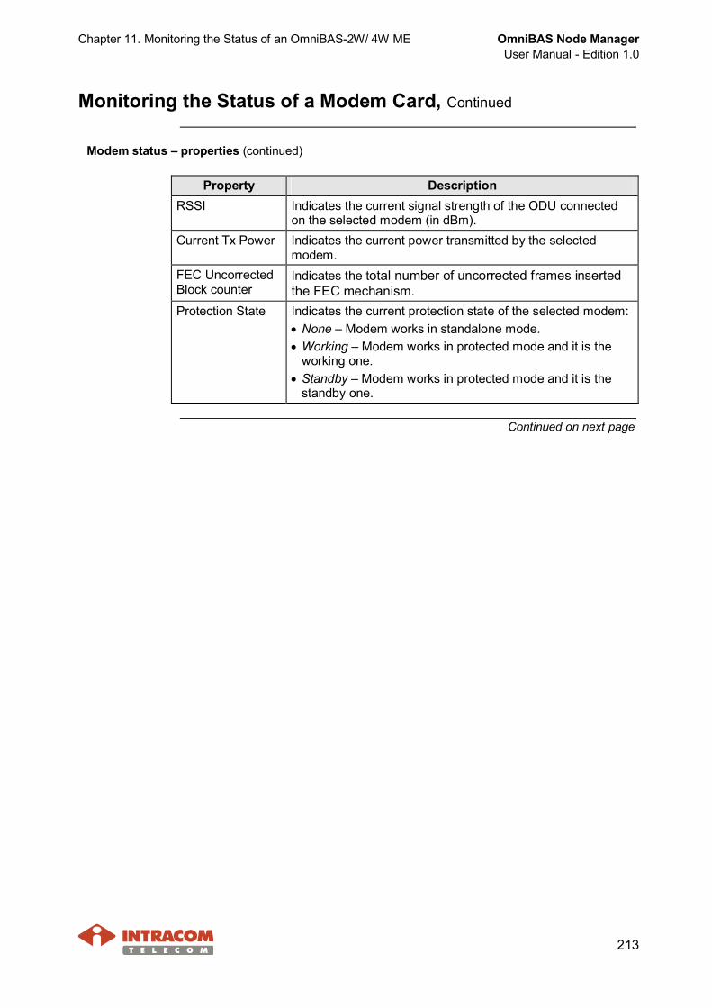
Chapter 11. Monitoring the Status of an OmniBAS-2W/ 4W ME OmniBAS Node ManagerUser Manual - Edition 1.0
213
Monitoring the Status of a Modem Card, Continued
Modem status – properties (continued)
Property DescriptionRSSI Indicates the current signal strength of the ODU connected
on the selected modem (in dBm).Current Tx Power Indicates the current power transmitted by the selected
modem.FEC UncorrectedBlock counter
Indicates the total number of uncorrected frames insertedthe FEC mechanism.
Protection State Indicates the current protection state of the selected modem:· None – Modem works in standalone mode.· Working – Modem works in protected mode and it is the
working one.· Standby – Modem works in protected mode and it is the
standby one.
Continued on next page

OmniBAS Node ManagerUser Manual - Edition 1.0
Chapter 11. Monitoring the Status of an OmniBAS-2W/ 4W ME
214
Monitoring the Status of a Modem Card, Continued
Remote modemstatus – properties
The following table describes the properties displayed in the RemoteModem group box.
Property DescriptionIP Address Indicates the IP address of the remote modem.Link Status(1) Indicates the Rx link status of the remote modem:
· Locked – Remote modem reception is Ok.· Unlocked – Link communication is failed. Remote modem
reception is not locked.· Failed – Link communication is failed. Remote modem status
cannot be retrieved. In this case the Remote Modem LinkFailed alarm (with ID = 14042 for OmniBAS-2W and ID = 6042for OmniBAS-4W) will be issued.
RemoteModem Slot
Indicates the slot position of the remote modem.
Modem status –Lock Indicators
The following table describes the properties displayed in the Lock Indicatorgroup box.
LockIndicator
Description
Timing Indicates if the selected modem is Locked or Unlocked in thesymbol timing of the received signal.
Preamble Indicates if the selected modem has detected (Locked) or not(Unlocked) the required distribution of preamble patterns in thereceived signal.
LDPC Unlock Indicates if the LDPC decoder of the selected modem is Lockedor Unlocked.
Continued on next page
(1) The right (green) state icon on the Modem card indicates that the corresponding remote Modem card islocked, while the right (red) state icon on the Modem card indicates that the remote Modem card is not locked.Also, the left (green) state icon on the Modem card indicates that the local Modem card is locked, while the left
(red) state icon on the Modem card indicates that the local Modem card is not locked.

Chapter 11. Monitoring the Status of an OmniBAS-2W/ 4W ME OmniBAS Node ManagerUser Manual - Edition 1.0
215
Monitoring the Status of a Modem Card, Continued
In the Configuration tabbed sheet(or Configuration Data window)of the selected OmniBAS-2WModem Card, click the Fan TrayInfo tab.
Monitoring ofOmniBAS-2Wmodem fans
Through the Fan Tray Info tabbed sheet you can monitor the physical state(Existence indications) and the operational status (Fan Tray Failure indication)of the Modem Card’s fans.
Alarm Alarm Indication DescriptionON - Green Fan module is in place.ExistenceOFF - Grey Fan module is not present. In this case, the
Fan Extracted alarm with ID = 14045 will beissued.
OFF - Grey Fan module operates normally.Fan TrayFailure ON - Red Fan module failure. In this case, the Fan
Failure alarm with ID = 14044 will be issued.
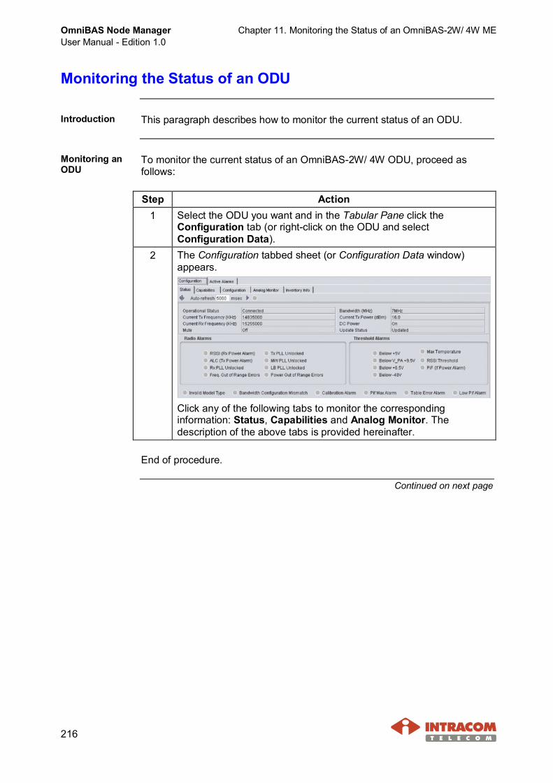
OmniBAS Node ManagerUser Manual - Edition 1.0
Chapter 11. Monitoring the Status of an OmniBAS-2W/ 4W ME
216
Monitoring the Status of an ODU
Introduction This paragraph describes how to monitor the current status of an ODU.
Monitoring anODU
To monitor the current status of an OmniBAS-2W/ 4W ODU, proceed asfollows:
Step Action1 Select the ODU you want and in the Tabular Pane click the
Configuration tab (or right-click on the ODU and selectConfiguration Data).
2 The Configuration tabbed sheet (or Configuration Data window)appears.
Click any of the following tabs to monitor the correspondinginformation: Status, Capabilities and Analog Monitor. Thedescription of the above tabs is provided hereinafter.
End of procedure.
Continued on next page
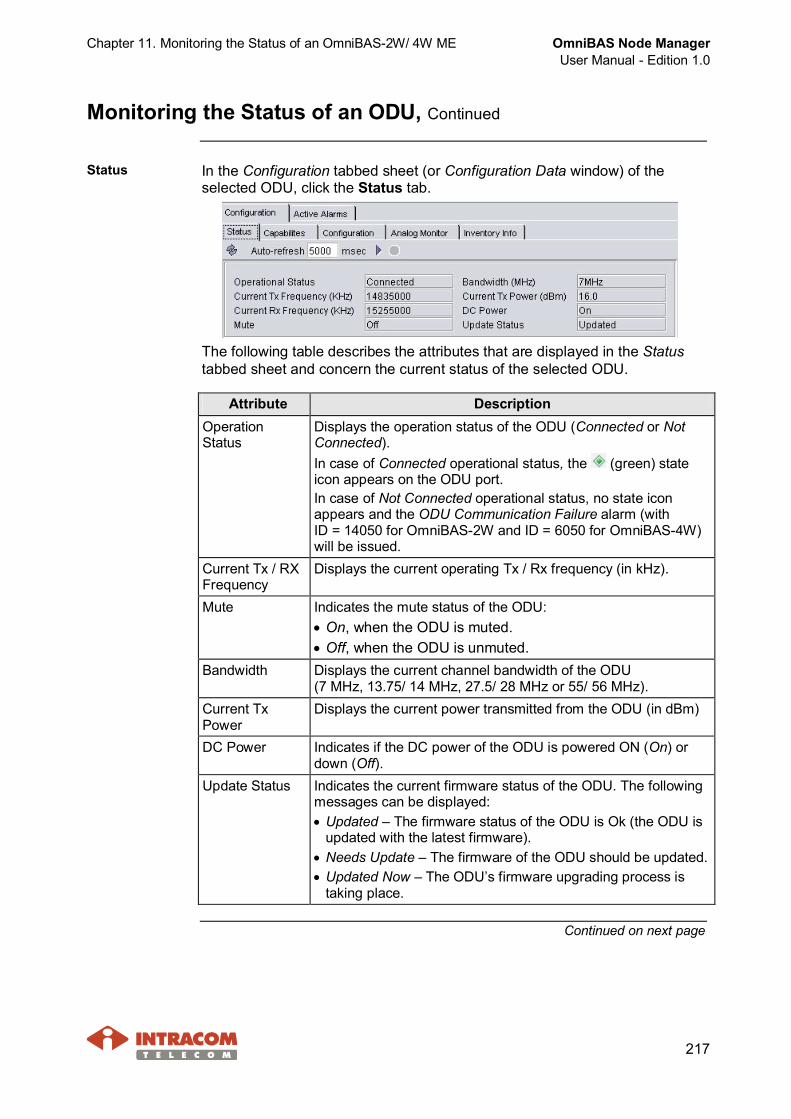
Chapter 11. Monitoring the Status of an OmniBAS-2W/ 4W ME OmniBAS Node ManagerUser Manual - Edition 1.0
217
Monitoring the Status of an ODU, Continued
Status In the Configuration tabbed sheet (or Configuration Data window) of theselected ODU, click the Status tab.
The following table describes the attributes that are displayed in the Statustabbed sheet and concern the current status of the selected ODU.
Attribute DescriptionOperationStatus
Displays the operation status of the ODU (Connected or NotConnected).In case of Connected operational status, the (green) stateicon appears on the ODU port.In case of Not Connected operational status, no state iconappears and the ODU Communication Failure alarm (withID = 14050 for OmniBAS-2W and ID = 6050 for OmniBAS-4W)will be issued.
Current Tx / RXFrequency
Displays the current operating Tx / Rx frequency (in kHz).
Mute Indicates the mute status of the ODU:· On, when the ODU is muted.· Off, when the ODU is unmuted.
Bandwidth Displays the current channel bandwidth of the ODU(7 MHz, 13.75/ 14 MHz, 27.5/ 28 MHz or 55/ 56 MHz).
Current TxPower
Displays the current power transmitted from the ODU (in dBm)
DC Power Indicates if the DC power of the ODU is powered ON (On) ordown (Off).
Update Status Indicates the current firmware status of the ODU. The followingmessages can be displayed:· Updated – The firmware status of the ODU is Ok (the ODU is
updated with the latest firmware).· Needs Update – The firmware of the ODU should be updated.· Updated Now – The ODU’s firmware upgrading process is
taking place.
Continued on next page
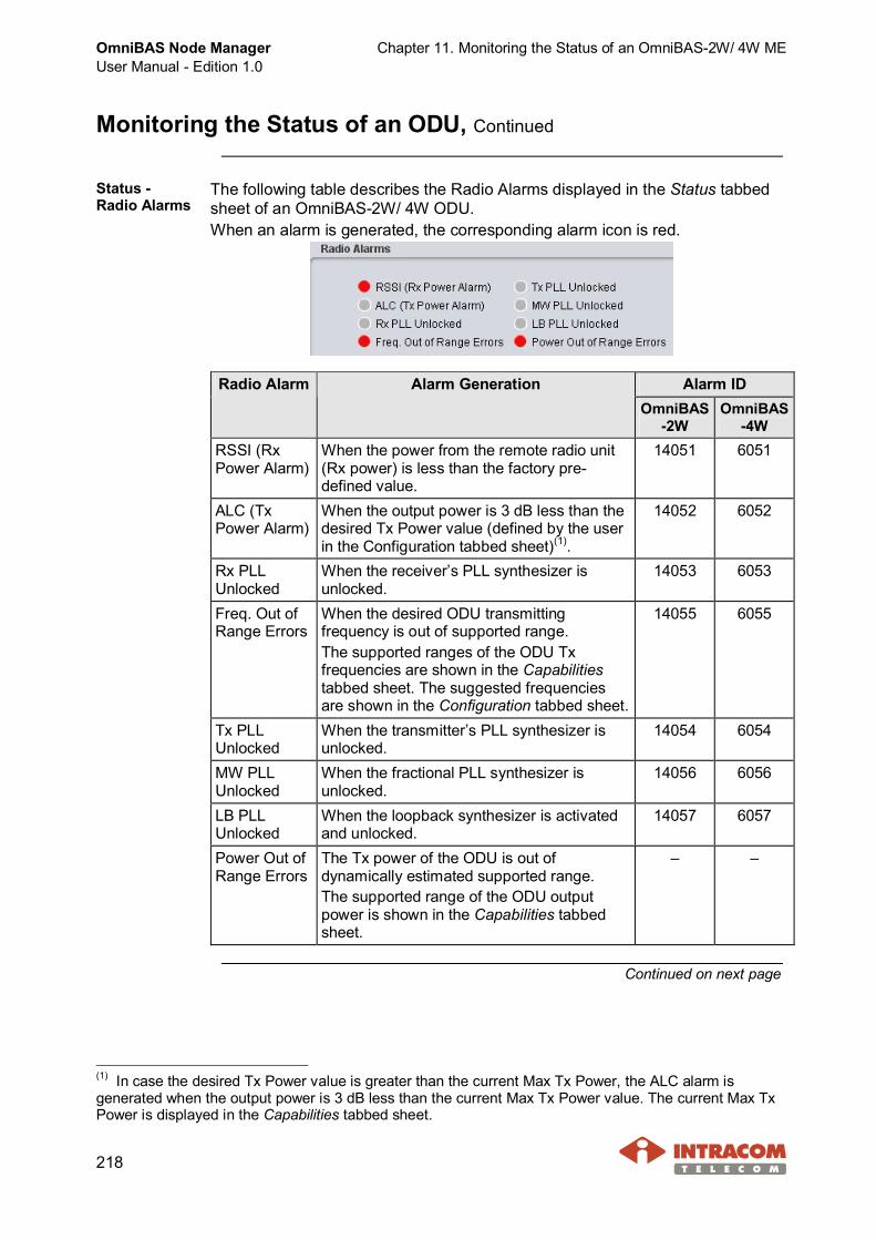
OmniBAS Node ManagerUser Manual - Edition 1.0
Chapter 11. Monitoring the Status of an OmniBAS-2W/ 4W ME
218
Monitoring the Status of an ODU, Continued
Status -Radio Alarms
The following table describes the Radio Alarms displayed in the Status tabbedsheet of an OmniBAS-2W/ 4W ODU.When an alarm is generated, the corresponding alarm icon is red.
Alarm IDRadio Alarm Alarm GenerationOmniBAS
-2WOmniBAS
-4WRSSI (RxPower Alarm)
When the power from the remote radio unit(Rx power) is less than the factory pre-defined value.
14051 6051
ALC (TxPower Alarm)
When the output power is 3 dB less than thedesired Tx Power value (defined by the userin the Configuration tabbed sheet)(1).
14052 6052
Rx PLLUnlocked
When the receiver’s PLL synthesizer isunlocked.
14053 6053
Freq. Out ofRange Errors
When the desired ODU transmittingfrequency is out of supported range.The supported ranges of the ODU Txfrequencies are shown in the Capabilitiestabbed sheet. The suggested frequenciesare shown in the Configuration tabbed sheet.
14055 6055
Tx PLLUnlocked
When the transmitter’s PLL synthesizer isunlocked.
14054 6054
MW PLLUnlocked
When the fractional PLL synthesizer isunlocked.
14056 6056
LB PLLUnlocked
When the loopback synthesizer is activatedand unlocked.
14057 6057
Power Out ofRange Errors
The Tx power of the ODU is out ofdynamically estimated supported range.The supported range of the ODU outputpower is shown in the Capabilities tabbedsheet.
– –
Continued on next page
(1) In case the desired Tx Power value is greater than the current Max Tx Power, the ALC alarm isgenerated when the output power is 3 dB less than the current Max Tx Power value. The current Max TxPower is displayed in the Capabilities tabbed sheet.

Chapter 11. Monitoring the Status of an OmniBAS-2W/ 4W ME OmniBAS Node ManagerUser Manual - Edition 1.0
219
Monitoring the Status of an ODU, Continued
Status -ConfigurationAlarms
The following table describes the Configuration Alarms displayed in theStatus tabbed sheet of an OmniBAS-2W/ 4W ODU.When an alarm is generated, the corresponding alarm icon is red.
Alarm IDAlarm Alarm GenerationOmniBAS
-2WOmniBAS
-4WInvalid ModelType
When the inserted ODU in the system hasan invalid (unsupported) model type.
– –
BandwidthConfigurationMismatch
When the bandwidth configuration of thecorresponding modem does not collocatewith the installed ODU hardware.
14091 6091
CalibrationAlarm
When an unsuccessful cable calibrationprocedure occurs.
14092 6092
Pif Max Alarm When the input power of the ODU is higherthan +3 dBm.
14093 6093
Low Pif Alarm When no ODU RF (350MHz) input isdetected during cable calibration procedure(alarm raised when ODU input power islower than -35 dBm).
14094 6094
Table ErrorAlarm
Alarm raised when ODU factory calibrationtables are erroneous.
14095 6095
Continued on next page

OmniBAS Node ManagerUser Manual - Edition 1.0
Chapter 11. Monitoring the Status of an OmniBAS-2W/ 4W ME
220
Monitoring the Status of an ODU, Continued
Status -ThresholdAlarms
The following table describes theThreshold Alarms displayed in theStatus tabbed sheet of anOmniBAS-2W/ 4W ODU.When an alarm is generated, thecorresponding alarm icon is red.
NOTE The threshold alarms displayed in the Threshold Alarms groupbox (and concern the ODU’s input/ output voltages) depend on thetype of the connected ODU.No threshold alarms for the ODU’s input/ output voltages aredisplayed when there is no connected ODU (1).
Alarm IDAlarm Alarm GenerationOmniBAS
-2WOmniBAS
-4WMaxTemperature
When the temperature inside the ODUexceeds the threshold you have set (throughthe Configuration tabbed sheet).
14062 6062
RSSIThreshold
When Rx power (i.e. power from the remoteradio unit) is less than the threshold youhave set (through the Configuration tabbedsheet).
14066 6066
PiF (If PowerAlarm)
When the power of the Tx IF signal fallsbelow -16.5 dBm.
14067 6067
Below -48V When the input voltage of the ODU fallsbelow -34V.
14060 6060
Below +5V When the output voltage of the ODU internalpower supply unit falls below +4.85V.
14065 6065
BelowV_PA+9.5V
When the output voltage of the ODU fallsbelow 8.5V.
14064 6064
Below +6.5V When the output voltage of the ODU internalpower supply unit falls below +6.3V.
14061 6061
Below -5V When the output voltage of the ODU internalpower supply unit falls below -4.7V.
14063 6063
BelowV_PA+12V
When the output voltage of the ODU fallsbelow 11.5V.
14064 6064
BelowV_PA+7.5V
When the output voltage of the ODU fallsbelow 7.3V.
14064 6064
Continued on next page
(1) When there is no connected ODU, the ODU Communication Failure alarm (with ID = 14050 forOmniBAS-2W and ID = 6050 for OmniBAS-4W) will be also issued.
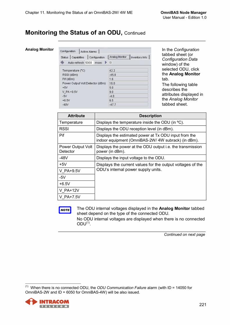
Chapter 11. Monitoring the Status of an OmniBAS-2W/ 4W ME OmniBAS Node ManagerUser Manual - Edition 1.0
221
Monitoring the Status of an ODU, Continued
Analog Monitor In the Configurationtabbed sheet (orConfiguration Datawindow) of theselected ODU, clickthe Analog Monitortab.The following tabledescribes theattributes displayed inthe Analog Monitortabbed sheet.
Attribute DescriptionTemperature Displays the temperature inside the ODU (in ºC).RSSI Displays the ODU reception level (in dBm).Pif Displays the estimated power at Tx ODU input from the
indoor equipment (OmniBAS-2W/ 4W subrack) (in dBm).Power Output VoltDetector
Displays the power at the ODU output i.e. the transmissionpower (in dBm).
-48V Displays the input voltage to the ODU.+5VV_PA+9.5V-5V+6.5VV_PA+12VV_PA+7.5V
Displays the current values for the output voltages of theODU’s internal power supply units.
NOTE The ODU internal voltages displayed in the Analog Monitor tabbedsheet depend on the type of the connected ODU.No ODU internal voltages are displayed when there is no connectedODU(1).
Continued on next page
(1) When there is no connected ODU, the ODU Communication Failure alarm (with ID = 14050 forOmniBAS-2W and ID = 6050 for OmniBAS-4W) will be also issued.

OmniBAS Node ManagerUser Manual - Edition 1.0
Chapter 11. Monitoring the Status of an OmniBAS-2W/ 4W ME
222
Monitoring the Status of an ODU, Continued
Capabilities In theConfigurationtabbed sheet (orConfigurationData window) ofthe selectedODU, click theCapabilities tab.
The following table describes the attributes concerning the capabilities of theconnected ODU.
Attribute DescriptionBand Displays the transmission radio band of the ODU (High or Low).SpectrumInversion
Indicates if spectrum inversion is required as far as Remote ODUtransmission to Local ODU reception (ON) or not (OFF).
Loopback SI Indicates if spectrum inversion is required as far as Local ODUtransmission to Local ODU reception (Loopback activated) (ON)or not (OFF).
FrequencyStep(1)
Displays the min frequency step supported by ODU for frequencychannel selection.
FirstFrequency
Displays the first frequency of the ODU transmission radio band(in kHz) for the current bandwidth selection.
LastFrequency
Displays the last frequency of the ODU transmission radio band(in kHz) for current bandwidth selection.
Max Tx Power Displays the dynamically calculated upper limit of the powerallowed for the specific modulation (in dBm).
Min Tx Power Displays the lower limit of the power allowed (in dBm).
(1) Not applicable for 8 GHz DS=311.32M ODU model.

Chapter 12. Monitoring the Real-Time Performance OmniBAS Node ManagerUser Manual - Edition 1.0
223
12 Monitoring the Real-Time Performance
This chapter describes how to monitor the real-time performance of anOmniBAS-2W/ 4W ME. The chapter includes the following topics:· Monitoring Real-Time GbE Performance· Monitoring the Real-Time Modem Performance· Monitoring the Real-Time Modem Ethernet Performance· Monitoring the Real-Time L2 Ports Statistics· Monitoring the Real-Time Performance of a PWE TDM Connection
NOTE The current release (3.2.0) of the OmniBAS Node Manager doesnot support the performance measurements for the OmniBAS-2WFast Ethernet ports.

OmniBAS Node ManagerUser Manual - Edition 1.0
Chapter 12. Monitoring the Real-Time Performance
224
Monitoring Real-Time GbE Performance
Introduction This paragraph describes how to monitor in real-time the GbE trafficpassing through the GbE port of an OmniBAS-2W/ 4W ME.
GbE PerformanceData/ Errors
To monitor in real-time the GbE traffic passing through the GbE port of anOmniBAS-2W/ 4W ME, proceed as follows:
Step Action1 Select the GbE port you want and in the Tabular Pane click the
Performance tab (or right-click on the GbE port and selectPerformance Measurements).
2 In the Performance tabbed sheet (or Performance Measurementswindow) that appears, the Performance Data tab is displayed - if notselect it.
The Performance Data tabbed sheet displays measurementsconcerning the packets received and transmitted by the selectedGbE port. The description of the statistic counters displayed in thePerformance Data tabbed sheet is provided hereinafter.
3 To view the error counters of the selected GbE port, click thePerformance Errors tab.
The description of the statistic counters displayed in the PerformanceErrors tabbed sheet is provided hereinafter.
4 To reset the collected statistics, click the button.
End of procedure.
Continued on next page
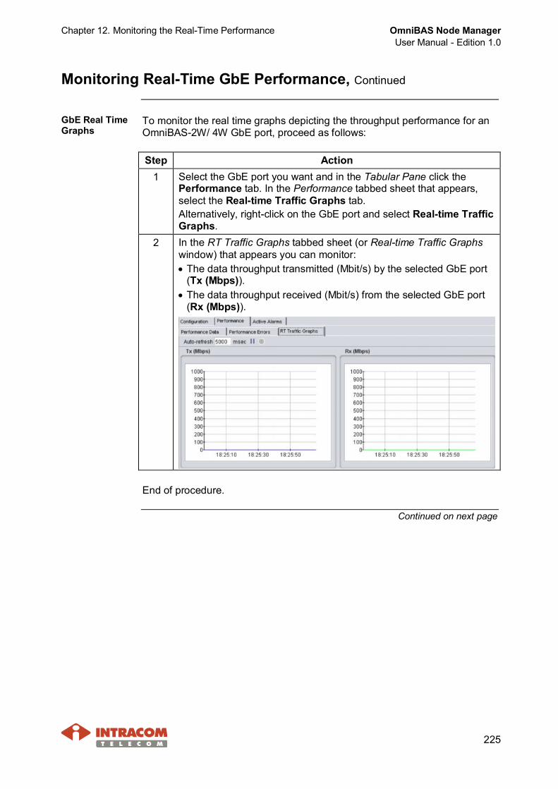
Chapter 12. Monitoring the Real-Time Performance OmniBAS Node ManagerUser Manual - Edition 1.0
225
Monitoring Real-Time GbE Performance, Continued
GbE Real TimeGraphs
To monitor the real time graphs depicting the throughput performance for anOmniBAS-2W/ 4W GbE port, proceed as follows:
Step Action1 Select the GbE port you want and in the Tabular Pane click the
Performance tab. In the Performance tabbed sheet that appears,select the Real-time Traffic Graphs tab.Alternatively, right-click on the GbE port and select Real-time TrafficGraphs.
2 In the RT Traffic Graphs tabbed sheet (or Real-time Traffic Graphswindow) that appears you can monitor:· The data throughput transmitted (Mbit/s) by the selected GbE port
(Tx (Mbps)).· The data throughput received (Mbit/s) from the selected GbE port
(Rx (Mbps)).
End of procedure.
Continued on next page

OmniBAS Node ManagerUser Manual - Edition 1.0
Chapter 12. Monitoring the Real-Time Performance
226
Monitoring Real-Time GbE Performance, Continued
PerformanceData - CountersDescription
The following table describes the statistic counters concerning the packetsreceived and transmitted by the GbE port of an OmniBAS-2W/ 4W ME.These counters are displayed in the Performance Data tabbed sheet of theGbE port.
Counter DescriptionTx Bytes Number of transmitted bytes.Tx Packets Number of transmitted packets transmitted.Tx MulticastFrames
Number of the transmitted multicast frames.
Tx BroadcastFrames
Number of the transmitted broadcast frames.
Tx OversizeFrames
Number of the oversized transmitted frames with a validFCS value.
Tx UndersizeFrames
Number of the transmitted frames that are less than 64bytes in length and with a valid FCS value.
Tx Frames Number of complete good frames transmitted.Tx ErrorUnderrun
Number of times that the Ethernet transmitter underunoccurred.
Rx Bytes Number of bytes received since the last counter reset.Rx Packets Number of packets received since the last counter reset.Rx MulticastFrames
Number of the multicast good frames received with size 64to 1518 (non VLAN) bytes in length or 1522 (VLAN) bytes inlength (excluding broadcast frames).
Rx BroadcastFrames
Number of the broadcast good frames received with size 64to 1518 (non VLAN) bytes in length or 1522 (VLAN) bytes inlength (excluding multicast frames).
Rx UndersizeFrames
Number of the received frames that are less than 64 bytesin length and with a valid FCS value.
Rx OversizeFrames
Number of the received frames that exceed 1518 bytes(non VLAN) or 1522 bytes (VLAN) in length and contain avalid FCS value.
Rx Error Overrun Number of the received Ethernet frames discarded due to areceive buffer overrun event (no available buffers).
Continued on next page

Chapter 12. Monitoring the Real-Time Performance OmniBAS Node ManagerUser Manual - Edition 1.0
227
Monitoring Real-Time GbE Performance, Continued
PerformanceErrors - CountersDescription
The following table describes the statistic counters concerning the packetsreceived and transmitted with errors by the GbE port of an OmniBAS-2W/4W ME. These counters are displayed in the Performance Errors tabbedsheet of the GbE port.
Counter DescriptionIn Pause Frames Number of received Pause frames (i.e. control frames
containing valid pause opcode). Pause frames are used topause the flow of traffic when traffic congestion occurs.
Out PauseFrames
Number of transmitted Pause frames (i.e. control framescontaining valid pause opcode). Pause frames are used topause the flow of traffic when traffic congestion occurs.
Out PauseHonored Frames
Number of pause frames not transmitted.
Alignment Errors Number of alignment errors for the received frames. Analignment error is caused when a received frame does notend on a byte boundary and the CRC does not match at thelast byte boundary.
FCS Errors Number of received valid size frames with FCS (FrameCheck Sequence) error but no framing errors.
Single CollisionFrames
Number of frames involved in a single collision butsubsequently are transmitted successfully.
Multiple CollisionFrames
Number of frames involved in more than one collision butsubsequently are transmitted successfully.
DeferredTransmissions
Number of transmitted frames deferred for an excessiveperiod of time.
Late Collisions Number of late collisions(1) detected.ExcessiveCollisions
Number of frames that, due to excessive collisions, arediscarded.
Carrier SenseErrors
Number of frames transmitted with carrier sense errors.This normally occurs as a result of collisions.
Frame Too Longs Number of received frames that exceed the maximumpermitted frame size.
Internal Macreceive Errors
Number of received packets discarded because of MACsub-layer error.
Symbol Errors Number of symbols received but not correctly decoded.
(1) Normal collisions occur during the first 512 bits of frame transmission. If a collision occurs after 512 bittimes, then it is considered an error and called a late collision. A late collision is a serious error, since itindicates a problem with the network system, and since it causes the frame being transmitted to bediscarded.

OmniBAS Node ManagerUser Manual - Edition 1.0
Chapter 12. Monitoring the Real-Time Performance
228
Monitoring the Real-Time Modem Performance
Introduction This paragraph describes how to monitor in real-time the performance of anOmniBAS-2W/ 4W modem.
Procedure To monitor in real-time the performance of an OmniBAS-2W/ 4W modem,proceed as follows:
Step Action1 Select the Modem Card you want and in the Tabular Pane click the
Performance tab. In the Performance tabbed sheet that appears,select the PTP Modem Performance Measurements tab.Alternatively, right-click on the Modem Card and select PerformanceMeasurements.
2 The PTP Modem Performance Measurements tabbed sheet (orPerformance Measurements window) appears.
Continued on next page

Chapter 12. Monitoring the Real-Time Performance OmniBAS Node ManagerUser Manual - Edition 1.0
229
Monitoring the Real-Time Modem Performance, Continued
Procedure (continued)
Step Action3 Through the Modem Performance Measurements tabbed sheet (or
Performance Measurements window), you can monitor:· Total time that the selected modem is in service (in the Total time in
service field).· Total time that the selected modem is out of service (in the Total
time out of service in service field).· Number of times that the physical modulation profile of the modem
has been changed (in the Number of PHY changes field).· In the Time in Service group box, you can view the total time that
each physical modulation profile has been in service.Note that the physical modulation profiles displayed in this group boxdepend on the configuration settings of the modem.
· In the FEC Counters(1) group box, you can view:- Number of LOL events: Number of Loss of Link events.- FEC Block: Total number of frames inserted the FEC mechanism.- FEC Uncorrected Block: Total number of uncorrected frames
inserted the FEC mechanism.4 To reset the collected statistics, click the button.
End of procedure.
(1) FEC (Forward Error Correction) - Reed-Solomon FEC encoding is used to add redundant parity bytesto data packets, in order to allow the detection and correction of burst errors introduced by the cable plant.

OmniBAS Node ManagerUser Manual - Edition 1.0
Chapter 12. Monitoring the Real-Time Performance
230
Monitoring the Real-Time Modem Ethernet Performance
Introduction This paragraph describes how to monitor in real-time the Ethernet trafficpassing through an OmniBAS-2W/ 4W ME modem.
Procedure To monitor in real-time the Ethernet traffic performance through anOmniBAS-2W/ 4W modem, proceed as follows:
Step Action1 Select the Modem Card you want and in the Tabular Pane click the
Performance tab. In the Performance tabbed sheet that appears,select the Ethernet Performance Measurements tab.Alternatively, right-click on the Modem Card and select EthernetPerformance Measurements.
2 In the Performance Measurements tabbed sheet (or window) thatappears the Tx (Air to Net) tab is displayed - if not select it.
The Tx (Air toNet) tabbed sheetdisplaysmeasurementsconcerning theEthernet packetstransmitted by themodem to theGbE and FE portsof the selectedOmniBAS-2W/4W ME.
To view thecountersconcerning theEthernet packetsreceived by theOmniBAS-2W/4W modem, clickthe Rx (Net toAir) tab.
The description of the statistic counters displayed in the above tabbedsheet is provided hereinafter.
Continued on next page
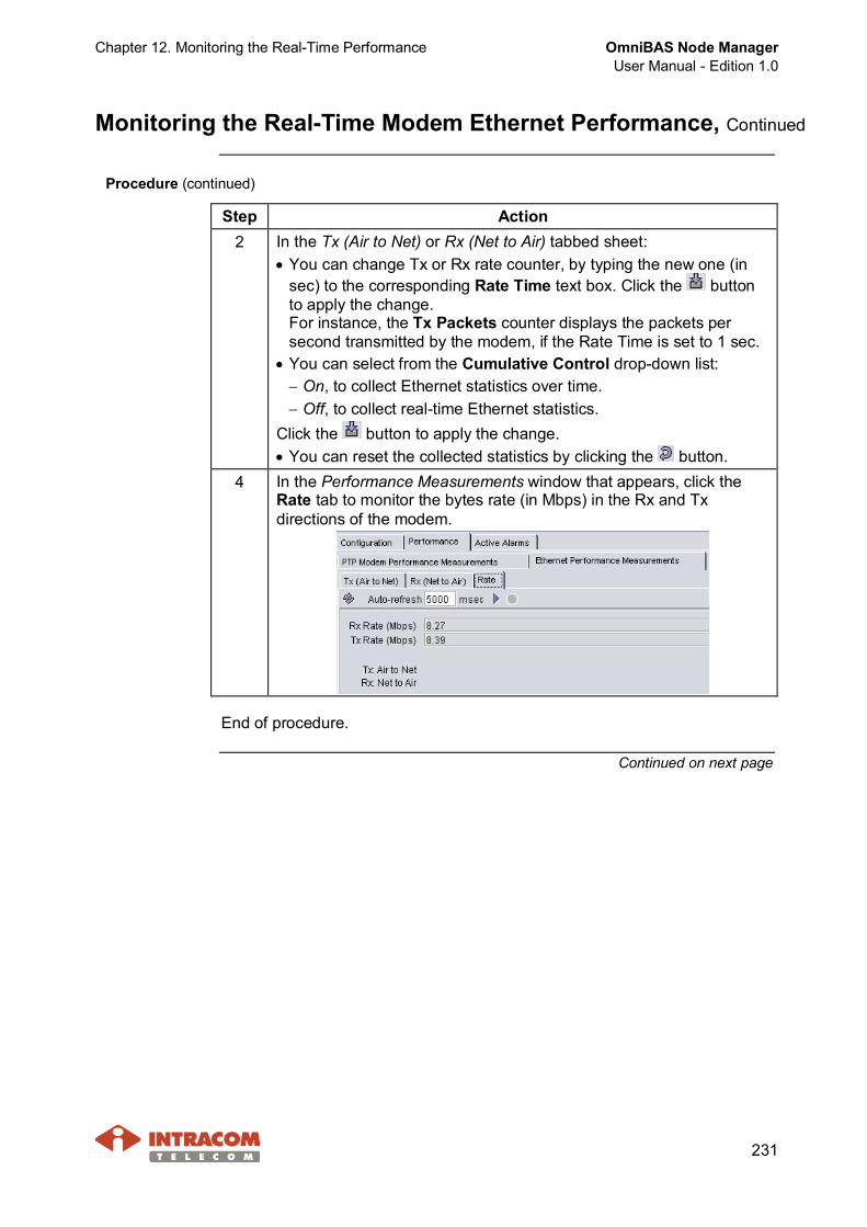
Chapter 12. Monitoring the Real-Time Performance OmniBAS Node ManagerUser Manual - Edition 1.0
231
Monitoring the Real-Time Modem Ethernet Performance, Continued
Procedure (continued)
Step Action2 In the Tx (Air to Net) or Rx (Net to Air) tabbed sheet:
· You can change Tx or Rx rate counter, by typing the new one (insec) to the corresponding Rate Time text box. Click the buttonto apply the change.For instance, the Tx Packets counter displays the packets persecond transmitted by the modem, if the Rate Time is set to 1 sec.
· You can select from the Cumulative Control drop-down list:- On, to collect Ethernet statistics over time.- Off, to collect real-time Ethernet statistics.
Click the button to apply the change.· You can reset the collected statistics by clicking the button.
4 In the Performance Measurements window that appears, click theRate tab to monitor the bytes rate (in Mbps) in the Rx and Txdirections of the modem.
End of procedure.
Continued on next page

OmniBAS Node ManagerUser Manual - Edition 1.0
Chapter 12. Monitoring the Real-Time Performance
232
Monitoring the Real-Time Modem Ethernet Performance, Continued
Tx (Air to Net)CountersDescription
This following table describes the statistic counters concerning the packetstransmitted from the modem to the GbE and FE ports of the selectedOmniBAS-2W/ 4W ME.
Counter DescriptionTx Packet Number of transmitted Ethernet frames.Tx VLAN Tags Number of transmitted VLAN-tagged frames.Tx BackPressures Events
Number of carrier-sense-method back-pressure previouslyapplied.
Tx Under Runs Number of frames not transmitted due to under-run errors.Tx Giants Number of frames discarded as they have length size
greater than the Max Frame Size of 1518 bytes (excludingpreamble).
Tx Late Collisions Number of late collisions(1) detected.Tx Max Collisions Number of frames aborted after number of collisions
exceeded the Retransmission Maximum parameter.Tx ExcessiveDefers
Number of transmitted frames deferred for an excessiveperiod of time.
Tx Non ExcessiveDefers
Number of frames successfully transmitted aftertransmission has been deferred at least once.
Tx Length CheckErrors
Number of transmitted frames with length that does notmatch the actual data byte length.
Tx Pause Frames Number of transmitted Pause frames (i.e. control framescontaining valid pause opcode).
Tx ControlFrames
Number of transmitted Control frames (i.e. frames contain avalid hex 0x8808 value in the type field).
Tx CRC Errors Number of transmitted frames with invalid CRC (CyclicRedundancy Check) value.
Tx Collisions Number of collisions the current frame incurred duringtransmission attempts. It applies to successfully transmittedpackets.
Tx Multicasts Number of transmitted multicast frames (i.e. framesincluding multicast destination address).
Tx Broadcasts Number of transmitted broadcast frames (i.e. framesincluding broadcast destination address).
Tx Wire Bytes Number of transmitted bytes, counting also all bytes fromcollided attempts.
Tx Bytes Number of transmitted bytes, not counting collided bytes.Cumulative Time Time in sec that the current Tx Ethernet statistics collected.
Continued on next page
(1) Normal collisions occur during the first 512 bits of frame transmission. If a collision occurs after 512 bittimes, then it is considered an error and called a late collision. A late collision is a serious error, since itindicates a problem with the network system, and since it causes the frame being transmitted to bediscarded.

Chapter 12. Monitoring the Real-Time Performance OmniBAS Node ManagerUser Manual - Edition 1.0
233
Monitoring the Real-Time Modem Ethernet Performance, Continued
Rx (Net to Air)CountersDescription
This following table describes the statistic counters concerning the packetsreceived by the OmniBAS-2W/ 4W modem.
Counter DescriptionRx Packet Number of received Ethernet frames.Rx CRC Errors Number of received frames with invalid CRC (Cyclic
Redundancy Check) value.Rx TruncatedFrames
Number of truncated received frames.
Rx Long Events Number of received overlong frames (i.e. frames havingbyte count greater than the maximum frame size).
Rx VLAN TagsDetected
Number of received VLAN-tagged frames.
Rx UnsupportedOpCodes
Number of received frames recognized as control framesbut contain unknown opcodes.
Rx Pause Frames Number of received Pause frames (i.e. frames recognizedas control frames containing valid pause opcode(2) and alsohave valid destination address).
Rx ControlFrames
Number of received Control frames (i.e. frames contain avalid hex 0x8808 value in the type field).
Rx DribbleNibbles
Number of received frames including dribble nibble (i.e.including extra 1 to 7 bits at the end of the frame). The extrabits are thrown away.
Rx Broadcasts Number of received broadcast frames (i.e. frames includingbroadcast destination address).
Rx Multicasts Number of received multicast frames (i.e. frames includingmulticast destination address).
Rx Out Of RangeErrors
Number of received frames with length field that exceedsthe 1518 bytes.
Rx Length CheckErrors
Number of received frames with length that does not matchthe actual data byte length.
Rx Code Errors Number of received frames including one or more nibblessignalled as errors.
Rx False CarrierErrors
Number of false carrier events detected (i.e. a false carrierevent detected after the last receive of a frame and it is notassociated with this packet).
Rx Dv Event Number of last received events that are too short to be validpackets.
Rx PreviousPacket Dropped
Number of packets dropped since the last receive.
Rx Bytes Number of received bytes, not counting collided bytes.Cumulative Time Time in sec that the current Rx Ethernet statistics collected.
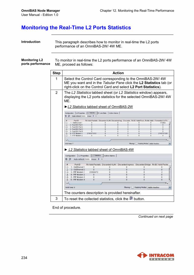
OmniBAS Node ManagerUser Manual - Edition 1.0
Chapter 12. Monitoring the Real-Time Performance
234
Monitoring the Real-Time L2 Ports Statistics
Introduction This paragraph describes how to monitor in real-time the L2 portsperformance of an OmniBAS-2W/ 4W ME.
Monitoring L2ports performance
To monitor in real-time the L2 ports performance of an OmniBAS-2W/ 4WME, proceed as follows:
Step Action1 Select the Control Card corresponding to the OmniBAS-2W/ 4W
ME you want and in the Tabular Pane click the L2 Statistics tab (orright-click on the Control Card and select L2 Port Statistics).
2 The L2 Statistics tabbed sheet (or L2 Statistics window) appears,displaying the L2 ports statistics for the selected OmniBAS-2W/ 4WME.►L2 Statistics tabbed sheet of OmniBAS-2W
► L2 Statistics tabbed sheet of OmniBAS-4W
The counters description is provided hereinafter.3 To reset the collected statistics, click the button.
End of procedure.
Continued on next page

Chapter 12. Monitoring the Real-Time Performance OmniBAS Node ManagerUser Manual - Edition 1.0
235
Monitoring the Real-Time L2 Ports Statistics, Continued
Monitoring theperformance ofan L2 port
To monitor in real-time the performance of an L2 port, proceed as follows:
Step Action1 Select the Control Card corresponding to the OmniBAS-2W/ 4W
ME you want and in the Tabular Pane click the L2 Properties tab(or right-click on the Control Card and select L2 Properties).
2 In the L2 Properties tabbed sheet (or L2 Properties window), clickthe L2 Port tab.
3 In the L2 Port tabbed sheet, right-click on the L2 port you want (e.g.OmniBAS-2W PTP Modem 1) and from the drop-down menu, selectStatistics.
4 The Statistics windowappears, displaying thestatistic counters of theselected L2 port.
5 To reset the collected statistics, click the button.
End of procedure.
Continued on next page
OmniBAS Node ManagerUser Manual - Edition 1.0
Chapter 12. Monitoring the Real-Time Performance
236
Monitoring the Real-Time L2 Ports Statistics, Continued
Statistic CountersDescription
This following table describes the statistic counters of the L2 ports for theselected OmniBAS-2W/ 4W ME:
Counter DescriptionRx Valid Packets Number of frames that passed all input filters.Discarded VLAN Number of frames that were discarded by the VLAN
acceptable filtering.Discarded Ingress Number of frames that were discarded by the ingress
filtering.Discarded Bridge Number of frames that were discarded by the classifier
(DFC deny).Rx BC Valid Packets Number of broadcast valid packets were receivedRx Mc Valid Packets Number of multicast valid packets were receivedForwarded UcPackets
Number of unicast frames that were forwarded.
Forwarded BcPackets
Number of broadcast frames that were forwarded.
Forwarded McPackets
Number of multicast frames that were forwarded.
Protocol Error Number of packets dropped due to protocol error.Forward Packets Number of valid packets forwarded by L2 port.Tx Queue DropPackets
Number of packets dropped due to a congestion in thetransmit queue.

Chapter 12. Monitoring the Real-Time Performance OmniBAS Node ManagerUser Manual - Edition 1.0
237
Monitoring the Real-Time Performance of a PWE TDMConnection
Introduction This paragraph describes how to monitor in real-time the performance of aPWE TDM connection of an OmniBAS-2W/ 4W ME.
Procedure To monitor the performance of a PWE TDM connection, proceed as follows:
Step Action1 Select the Control Card corresponding to the OmniBAS-2W/ 4W ME
you want and in the Tabular Pane click the L2 Properties tab (orright-click on the Control Card and select L2 Properties).
2 In the L2 Properties tabbed sheet (or L2 Properties window), click theTDM tab. In the TDM tabbed sheet, right-click on the PWE TDMconnection you want and from the drop-down menu, selectPerformance Measurements.
3 The Performance Measurements window appears, displaying thestatistics for the selected PWE TDM connection.
The counters description is provided hereinafter.4 To reset the collected statistics, click the button.
Continued on next page

OmniBAS Node ManagerUser Manual - Edition 1.0
Chapter 12. Monitoring the Real-Time Performance
238
Monitoring the Real-Time Performance of a PWE TDMConnection, Continued
CountersDescription
This following table describes the statistic counters concerning a PWE TDMconnection of an OmniBAS-2W/ 4W ME.
Counter DescriptionTDM to
PSNTransmittedPackets
Number of packets successfully transmitted toPSN side.
Received ValidPackets
Number of valid packets received in PSN side.
Jitter BufferUnderruns
Number of times that TDM transmit underrunoccurred due to no packets received from PSNside.
Jitter BufferOverruns
How many times received packets were rejecteddue to Jitter buffer overrun on TDM side.
Lost Packets Number of lost packets.Out of SequencePackets
Number of packets detected out of sequence, butsuccessfully re-ordered.
PSN toTDM
MalformedPackets
Number of malformed packets detected anddiscarded. Malformed packets are detected bymismatch between the expected packet size andthe actual packet size inferred from the PSN.

Chapter 13. Fault Management OmniBAS Node ManagerUser Manual - Edition 1.0
239
13 Fault Management
This chapter provides all necessary information for performing the faultmanagement of one or two OmniBAS-2W/ 4W MEs through the OmniBASNode Manager. The chapter includes the following topics:· Viewing Active Alarms· Alarms Properties· Active Alarms Toolbar· Acknowledging an Alarm· Clearing an Alarm· Alarms Supported by OmniBAS Node Manager

OmniBAS Node ManagerUser Manual - Edition 1.0
Chapter 13. Fault Management
240
Viewing Active Alarms
Introduction This paragraph describes how to view the:· Active Alarms list of all connected OmniBAS-2W/ 4W MEs/ MOs.· Active Alarms list of an OmniBAS-2W/ 4W ME/ MO.
NOTE OmniBAS Node Manager gets automatically aware of theOmniBAS-2W/ 4W alarms, as the auto-refreshing / auto-synchronization of the Active Alarms lists is activated by default.Thus, when you insert/ extract a module in/ from the OmniBAS-2W/4W subrack, the OmniBAS Node Manager gets automatically awareof the OmniBAS-2W/ 4W alarms (i.e. no synchronization actionsyou need to perform).
Viewing ActiveAlarms list ofall MEs/ MOs
To view the Active Alarms list of all OmniBAS-2W/ 4W MEs/ MOs, proceed asfollows:
Step Action1 In the uni|MS Node
Manager window,click the ActiveAlarms perspective
2 The Active Alarms list appears displaying all the active alarmsgenerated by the connected OmniBAS-2W/ 4W MEs, cards andports since the launching of the OmniBAS Node Manager. Activealarms are all these that concern active faults.
Continued on next page

Chapter 13. Fault Management OmniBAS Node ManagerUser Manual - Edition 1.0
241
Viewing Active Alarms, Continued
Viewing Active Alarms list of all MEs/ MOs (continued)
Step Action3 When you right-click on an alarm, a drop-down menu appears,
through which you can select:· To acknowledge or clear the alarm.· To perform configuration or performance management on the ME,
card or port (1) from which the alarm comes.
End of procedure.
(1) The name of the ME, card or port generates the alarm is displayed in the Source alarm property(column).
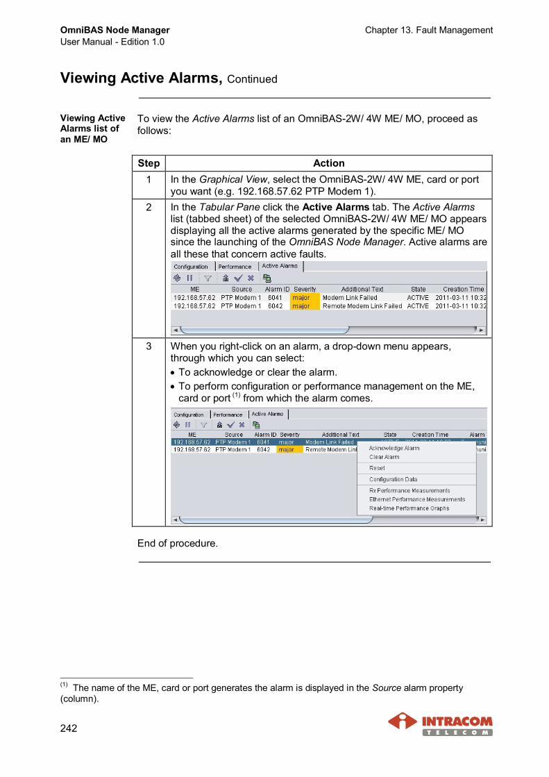
OmniBAS Node ManagerUser Manual - Edition 1.0
Chapter 13. Fault Management
242
Viewing Active Alarms, Continued
Viewing ActiveAlarms list ofan ME/ MO
To view the Active Alarms list of an OmniBAS-2W/ 4W ME/ MO, proceed asfollows:
Step Action1 In the Graphical View, select the OmniBAS-2W/ 4W ME, card or port
you want (e.g. 192.168.57.62 PTP Modem 1).2 In the Tabular Pane click the Active Alarms tab. The Active Alarms
list (tabbed sheet) of the selected OmniBAS-2W/ 4W ME/ MO appearsdisplaying all the active alarms generated by the specific ME/ MOsince the launching of the OmniBAS Node Manager. Active alarms areall these that concern active faults.
3 When you right-click on an alarm, a drop-down menu appears,through which you can select:· To acknowledge or clear the alarm.· To perform configuration or performance management on the ME,
card or port (1) from which the alarm comes.
End of procedure.
(1) The name of the ME, card or port generates the alarm is displayed in the Source alarm property(column).

Chapter 13. Fault Management OmniBAS Node ManagerUser Manual - Edition 1.0
243
Alarms Properties
Introduction This paragraph describes the properties of the Active Alarms supported byOmniBAS Node Manager.
Alarms propertiesdescription
The following table describes the Active Alarms properties.
Property Description ExampleME Indicates the IP address of the ME from which
the alarm comes.192.168.57.62
Source Indicates the exact managed object (ME, Card,or Port) generates the alarm.
E1 1
Alarm ID Indicates the unique number used to identify thealarm.
6070
Severity(1) Indicates the severity of the alarm. See also thefollowing par. About alarms severity.
major
State Indicates the state of the alarm, Active orAcknowledge. An Active alarm is generatedwhen uniMS receives a ME trap denoting fault.When the user acknowledges an active alarm,the alarm state changes to Acknowledge.
Acknowledged
AdditionalText
Indicates the additional text introduced by theuser.
E1 Line LOS
CreationTime
Indicates the date and time the alarm wasgenerated at the ME.
2011-03-1109:06:33.000
Alarm Type Indicates the type of the alarm. Available values:Communications, Quality of Service, ProcessingError, Equipment and Environmental.
Communications
Continued on next page
(1) No fault administration is supported by OmniBAS Node Manager. Hence, you cannot change the alarmsdefault severity.
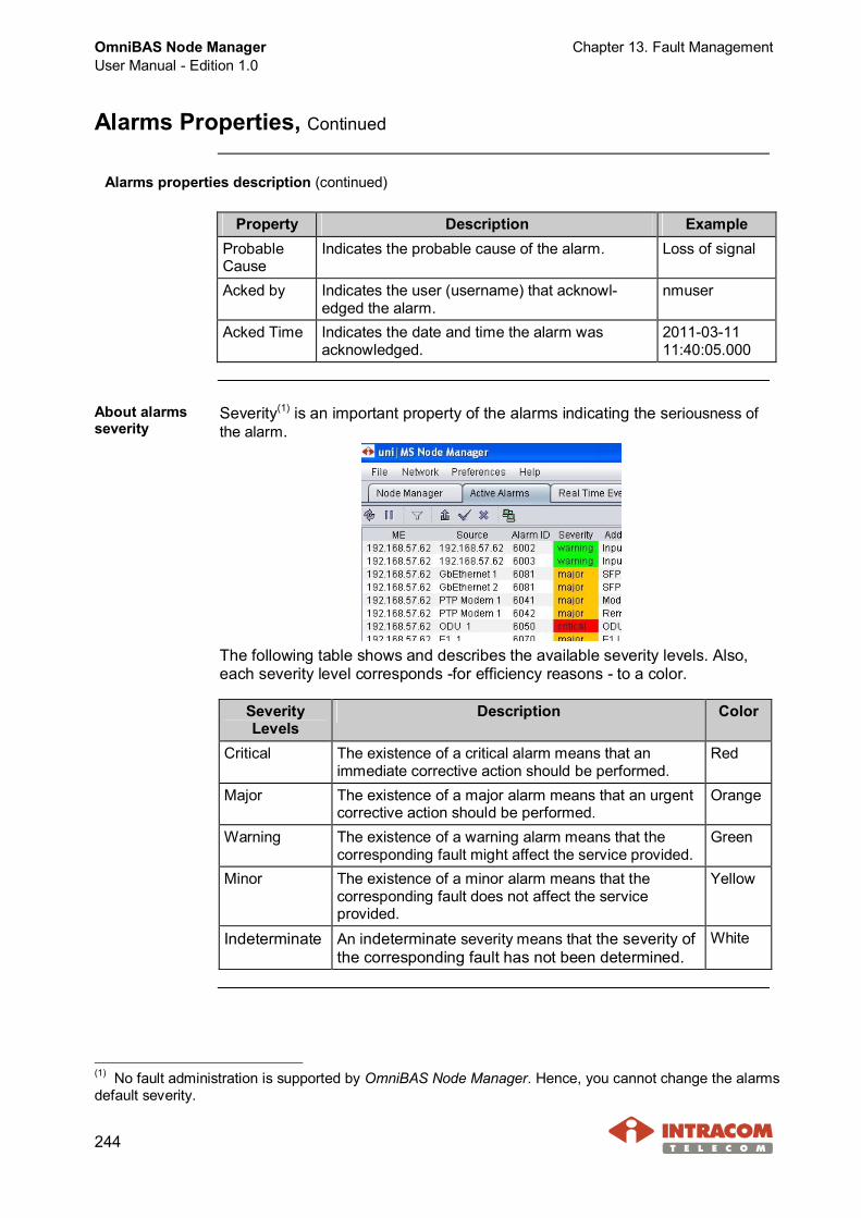
OmniBAS Node ManagerUser Manual - Edition 1.0
Chapter 13. Fault Management
244
Alarms Properties, Continued
Alarms properties description (continued)
Property Description ExampleProbableCause
Indicates the probable cause of the alarm. Loss of signal
Acked by Indicates the user (username) that acknowl-edged the alarm.
nmuser
Acked Time Indicates the date and time the alarm wasacknowledged.
2011-03-1111:40:05.000
About alarmsseverity
Severity(1) is an important property of the alarms indicating the seriousness ofthe alarm.
The following table shows and describes the available severity levels. Also,each severity level corresponds -for efficiency reasons - to a color.
SeverityLevels
Description Color
Critical The existence of a critical alarm means that animmediate corrective action should be performed.
Red
Major The existence of a major alarm means that an urgentcorrective action should be performed.
Orange
Warning The existence of a warning alarm means that thecorresponding fault might affect the service provided.
Green
Minor The existence of a minor alarm means that thecorresponding fault does not affect the serviceprovided.
Yellow
Indeterminate An indeterminate severity means that the severity ofthe corresponding fault has not been determined.
White
(1) No fault administration is supported by OmniBAS Node Manager. Hence, you cannot change the alarmsdefault severity.
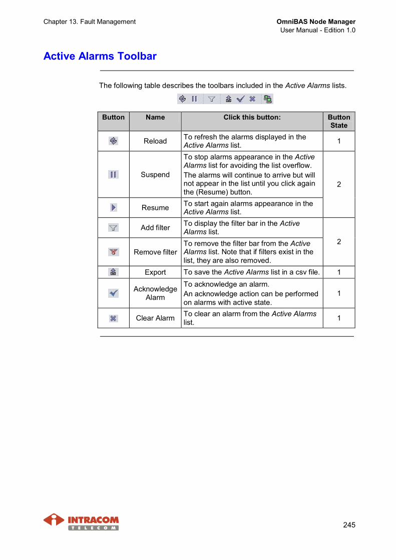
Chapter 13. Fault Management OmniBAS Node ManagerUser Manual - Edition 1.0
245
Active Alarms Toolbar
The following table describes the toolbars included in the Active Alarms lists.
Button Name Click this button: ButtonState
Reload To refresh the alarms displayed in theActive Alarms list. 1
Suspend
To stop alarms appearance in the ActiveAlarms list for avoiding the list overflow.The alarms will continue to arrive but willnot appear in the list until you click againthe (Resume) button.
Resume To start again alarms appearance in theActive Alarms list.
2
Add filter To display the filter bar in the ActiveAlarms list.
Remove filterTo remove the filter bar from the ActiveAlarms list. Note that if filters exist in thelist, they are also removed.
2
Export To save the Active Alarms list in a csv file. 1
AcknowledgeAlarm
To acknowledge an alarm.An acknowledge action can be performedon alarms with active state.
1
Clear Alarm To clear an alarm from the Active Alarmslist. 1
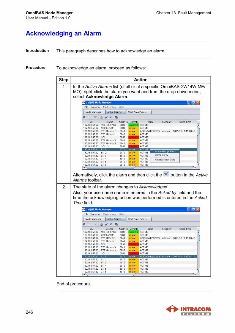
OmniBAS Node ManagerUser Manual - Edition 1.0
Chapter 13. Fault Management
246
Acknowledging an Alarm
Introduction This paragraph describes how to acknowledge an alarm.
Procedure To acknowledge an alarm, proceed as follows:
Step Action1 In the Active Alarms list (of all or of a specific OmniBAS-2W/ 4W ME/
MO), right-click the alarm you want and from the drop-down menu,select Acknowledge Alarm.
Alternatively, click the alarm and then click the button in the ActiveAlarms toolbar.
2 The state of the alarm changes to Acknowledged.Also, your username name is entered in the Acked by field and thetime the acknowledging action was performed is entered in the AckedTime field.
End of procedure.

Chapter 13. Fault Management OmniBAS Node ManagerUser Manual - Edition 1.0
247
Clearing an Alarm
Introduction This paragraph describes how to clear an alarm.
Procedure To clear an alarm from an Active Alarms list, proceed as follows:
Step Action1 In the Active Alarms list (of all or of a specific OmniBAS-2W/ 4W ME/
MO), right-click the alarm you want and from the drop-down menu,select Clear Alarm.
Alternatively, click the alarm and then click the button in the ActiveAlarms toolbar.
2 The alarm is removed from the Active Alarms list.
End of procedure.

OmniBAS Node ManagerUser Manual - Edition 1.0
Chapter 13. Fault Management
248
Alarms Supported by OmniBAS Node Manager
This following table lists the alarms supported by OmniBAS Node Manager forthe OmniBAS-2W/ 4W MEs.
Alarm ID
OB-2W OB-4W
Source(Object Type)
Alarm Description Severity (default) (1)
3 3 Core Lost communication with element. Critical
4 4 Core Equipment extracted Major
5 5 Core Equipment in a used slot Critical
14002 6002 ME Input Alarm 1 Warning
14003 6003 ME Input Alarm 2 Warning
14004 – ME Input Alarm 3 Warning
14005 – ME Input Alarm 4 Warning
– 6011 ME PSU Failure Major
14021 6021 Control Card High Temperature Critical
14040 6040 PTP Modem Modem Failure Major
14041 6041 PTP Modem Modem Link Failed Major
14042 6042 PTP Modem Remote Modem Link Failed Major
– 6043 PTP Modem Invalid Modem Inserted Major
14044 6044 Fan Failure Critical
14045 –
PTP Modem(for OB-2W),ME (for OB-4W) Fan Extracted Critical
14050 6050 ODU ODU Communication Failure Critical
14051 6051 ODU ODU RSSI Alarm Major
14052 6052 ODU ODU Pout ALC Alarm Critical
14053 6053 ODU ODU Rx PLL LD Alarm Critical
14054 6054 ODU ODU Tx PLL LD Alarm Critical
14055 6055 ODU ODU Tx Frequency Out of RangeAlarm
Major
14056 6056 ODU ODU MW PLL LD Alarm Critical
14057 6057 ODU ODU Loopback PLL LD Alarm Minor
– 6058 ODU Tx ODU Power Out of Range Alarm Warning
14060 6060 ODU ODU -48V Voltage Alarm Warning
Continued on next page
(1) No fault administration is supported by OmniBAS Node Manager. Hence, you cannot change the alarmsdefault severity.
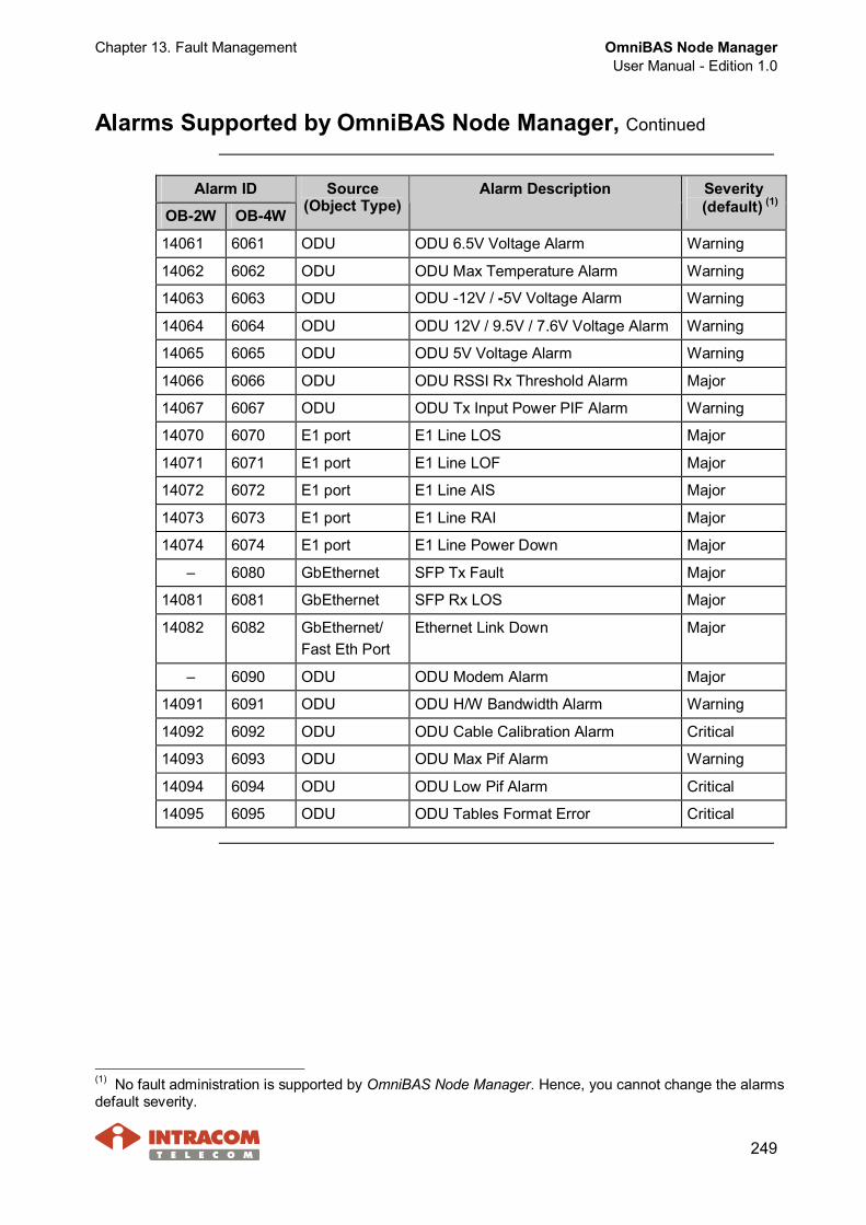
Chapter 13. Fault Management OmniBAS Node ManagerUser Manual - Edition 1.0
249
Alarms Supported by OmniBAS Node Manager, Continued
Alarm ID
OB-2W OB-4W
Source(Object Type)
Alarm Description Severity (default) (1)
14061 6061 ODU ODU 6.5V Voltage Alarm Warning
14062 6062 ODU ODU Max Temperature Alarm Warning
14063 6063 ODU ODU -12V / -5V Voltage Alarm Warning
14064 6064 ODU ODU 12V / 9.5V / 7.6V Voltage Alarm Warning
14065 6065 ODU ODU 5V Voltage Alarm Warning
14066 6066 ODU ODU RSSI Rx Threshold Alarm Major
14067 6067 ODU ODU Tx Input Power PIF Alarm Warning
14070 6070 E1 port E1 Line LOS Major
14071 6071 E1 port E1 Line LOF Major
14072 6072 E1 port E1 Line AIS Major
14073 6073 E1 port E1 Line RAI Major
14074 6074 E1 port E1 Line Power Down Major
– 6080 GbEthernet SFP Tx Fault Major
14081 6081 GbEthernet SFP Rx LOS Major
14082 6082 GbEthernet/Fast Eth Port
Ethernet Link Down Major
– 6090 ODU ODU Modem Alarm Major
14091 6091 ODU ODU H/W Bandwidth Alarm Warning
14092 6092 ODU ODU Cable Calibration Alarm Critical
14093 6093 ODU ODU Max Pif Alarm Warning
14094 6094 ODU ODU Low Pif Alarm Critical
14095 6095 ODU ODU Tables Format Error Critical
(1) No fault administration is supported by OmniBAS Node Manager. Hence, you cannot change the alarmsdefault severity.

OmniBAS Node ManagerUser Manual - Edition 1.0
Chapter 14. Monitoring Real Time Events
250
14 Monitoring Real Time Events
This chapter provides all necessary information for monitoring the real timeevents occurring in the OmniBAS Node Manager.The chapter includes the following topics:· Monitoring Real Time Events List· Real Time Events Properties· Real Time Events Toolbar· Clearing the Real Time Events List· Events Supported by OmniBAS Node Manager
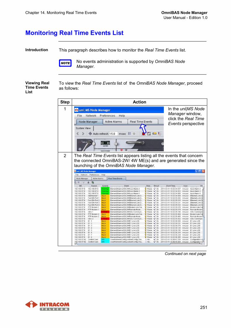
Chapter 14. Monitoring Real Time Events OmniBAS Node ManagerUser Manual - Edition 1.0
251
Monitoring Real Time Events List
Introduction This paragraph describes how to monitor the Real Time Events list.
NOTE No events administration is supported by OmniBAS NodeManager.
Viewing RealTime EventsList
To view the Real Time Events list of the OmniBAS Node Manager, proceedas follows:
Step Action1 In the uni|MS Node
Manager window,click the Real TimeEvents perspective
2 The Real Time Events list appears listing all the events that concernthe connected OmniBAS-2W/ 4W ME(s) and are generated since thelaunching of the OmniBAS Node Manager.
Continued on next page
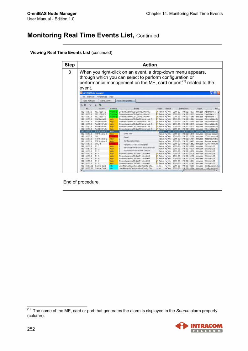
OmniBAS Node ManagerUser Manual - Edition 1.0
Chapter 14. Monitoring Real Time Events
252
Monitoring Real Time Events List, Continued
Viewing Real Time Events List (continued)
Step Action3 When you right-click on an event, a drop-down menu appears,
through which you can select to perform configuration orperformance management on the ME, card or port (1) related to theevent.
End of procedure.
(1) The name of the ME, card or port that generates the alarm is displayed in the Source alarm property(column).

Chapter 14. Monitoring Real Time Events OmniBAS Node ManagerUser Manual - Edition 1.0
253
Real Time Events Properties
Introduction This paragraph describes the properties of the Real Time Eventssupported by OmniBAS Node Manager.
NOTE No events administration is supported by OmniBAS Node Manager.
Alarms propertiesdescription
The following table describes the properties of the Real Time Events.
Property Description ExampleME Indicates the IP address of the ME from which
the event comes.192.168.48.71
Source Indicates the exact managed object (ME,Card, or Port) from which the event comes.
Fast Eth Port 2
Severity Indicates the severity of the event. See alsothe following par. About events severity, onpage 254.
Major
Event Indicates the description of the event. Element/Alarms/OB-2W/Ethernet LinkDown
Event Time Indicates the date and time the eventoccurred.
2010-12-1515:41:26.000
User Indicates the user who performed the event. nmuserInfo Represents additional information concerning
the event.Ethernet LinkDown
Result Indicates if the event succeeded to beexecuted (Ok) or not (Fail).
Ok
Continued on next page
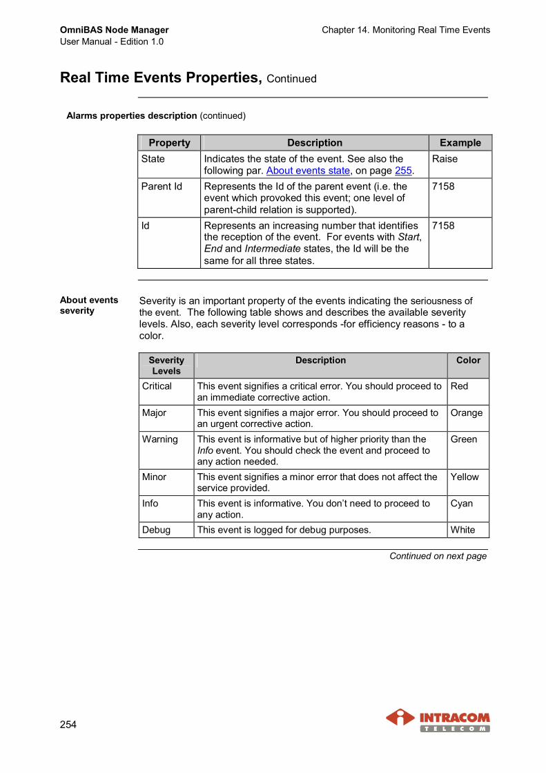
OmniBAS Node ManagerUser Manual - Edition 1.0
Chapter 14. Monitoring Real Time Events
254
Real Time Events Properties, Continued
Alarms properties description (continued)
Property Description ExampleState Indicates the state of the event. See also the
following par. About events state, on page 255.Raise
Parent Id Represents the Id of the parent event (i.e. theevent which provoked this event; one level ofparent-child relation is supported).
7158
Id Represents an increasing number that identifiesthe reception of the event. For events with Start,End and Intermediate states, the Id will be thesame for all three states.
7158
About eventsseverity
Severity is an important property of the events indicating the seriousness ofthe event. The following table shows and describes the available severitylevels. Also, each severity level corresponds -for efficiency reasons - to acolor.
SeverityLevels
Description Color
Critical This event signifies a critical error. You should proceed toan immediate corrective action.
Red
Major This event signifies a major error. You should proceed toan urgent corrective action.
Orange
Warning This event is informative but of higher priority than theInfo event. You should check the event and proceed toany action needed.
Green
Minor This event signifies a minor error that does not affect theservice provided.
Yellow
Info This event is informative. You don’t need to proceed toany action.
Cyan
Debug This event is logged for debug purposes. White
Continued on next page
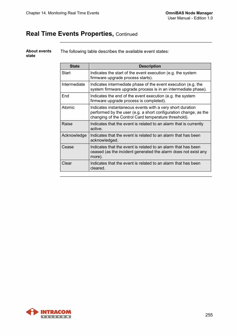
Chapter 14. Monitoring Real Time Events OmniBAS Node ManagerUser Manual - Edition 1.0
255
Real Time Events Properties, Continued
About eventsstate
The following table describes the available event states:
State DescriptionStart Indicates the start of the event execution (e.g. the system
firmware upgrade process starts).Intermediate Indicates intermediate phase of the event execution (e.g. the
system firmware upgrade process is in an intermediate phase).End Indicates the end of the event execution (e.g. the system
firmware upgrade process is completed).Atomic Indicates instantaneous events with a very short duration
performed by the user (e.g. a short configuration change, as thechanging of the Control Card temperature threshold).
Raise Indicates that the event is related to an alarm that is currentlyactive.
Acknowledge Indicates that the event is related to an alarm that has beenacknowledged.
Cease Indicates that the event is related to an alarm that has beenceased (as the incident generated the alarm does not exist anymore).
Clear Indicates that the event is related to an alarm that has beencleared.
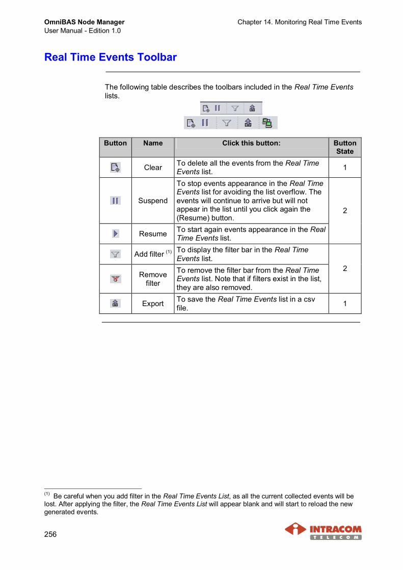
OmniBAS Node ManagerUser Manual - Edition 1.0
Chapter 14. Monitoring Real Time Events
256
Real Time Events Toolbar
The following table describes the toolbars included in the Real Time Eventslists.
Button Name Click this button: ButtonState
Clear To delete all the events from the Real TimeEvents list. 1
Suspend
To stop events appearance in the Real TimeEvents list for avoiding the list overflow. Theevents will continue to arrive but will notappear in the list until you click again the(Resume) button.
Resume To start again events appearance in the RealTime Events list.
2
Add filter (1) To display the filter bar in the Real TimeEvents list.
Removefilter
To remove the filter bar from the Real TimeEvents list. Note that if filters exist in the list,they are also removed.
2
Export To save the Real Time Events list in a csvfile. 1
(1) Be careful when you add filter in the Real Time Events List, as all the current collected events will belost. After applying the filter, the Real Time Events List will appear blank and will start to reload the newgenerated events.
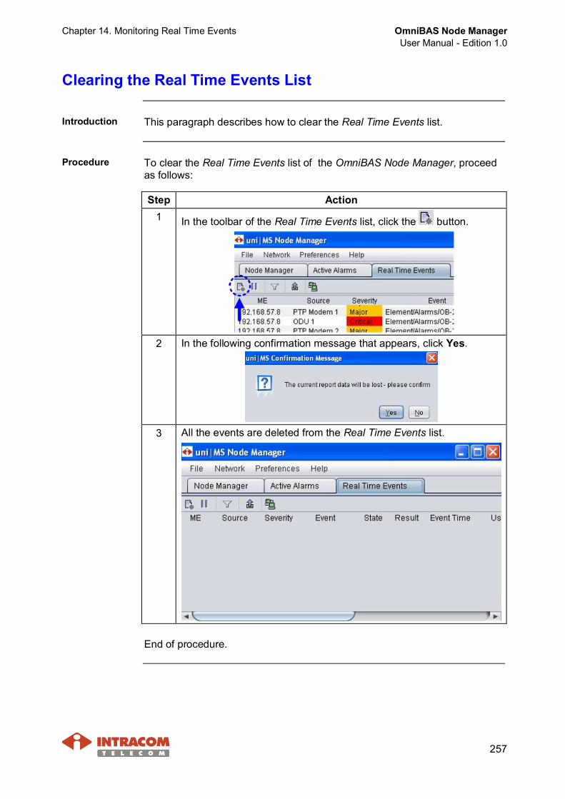
Chapter 14. Monitoring Real Time Events OmniBAS Node ManagerUser Manual - Edition 1.0
257
Clearing the Real Time Events List
Introduction This paragraph describes how to clear the Real Time Events list.
Procedure To clear the Real Time Events list of the OmniBAS Node Manager, proceedas follows:
Step Action1 In the toolbar of the Real Time Events list, click the button.
2 In the following confirmation message that appears, click Yes.
3 All the events are deleted from the Real Time Events list.
End of procedure.
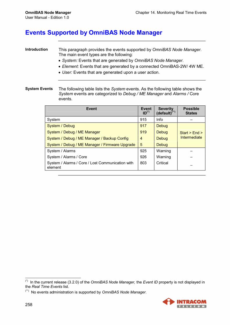
OmniBAS Node ManagerUser Manual - Edition 1.0
Chapter 14. Monitoring Real Time Events
258
Events Supported by OmniBAS Node Manager
Introduction This paragraph provides the events supported by OmniBAS Node Manager.The main event types are the following:· System: Events that are generated by OmniBAS Node Manager.· Element: Events that are generated by a connected OmniBAS-2W/ 4W ME.· User: Events that are generated upon a user action.
System Events The following table lists the System events. As the following table shows theSystem events are categorized to Debug / ME Manager and Alarms / Coreevents.
Event EventID(*)
Severity(default)(**)
PossibleStates
System 915 Info –System / Debug 917 DebugSystem / Debug / ME Manager 919 DebugSystem / Debug / ME Manager / Backup Config 4 DebugSystem / Debug / ME Manager / Firmware Upgrade 5 Debug
Start > End >Intermediate
System / Alarms 925 Warning –System / Alarms / Core 926 Warning –System / Alarms / Core / Lost Communication withelement
803 Critical –
(*) In the current release (3.2.0) of the OmniBAS Node Manager, the Event ID property is not displayed inthe Real Time Events list.(**) No events administration is supported by OmniBAS Node Manager.
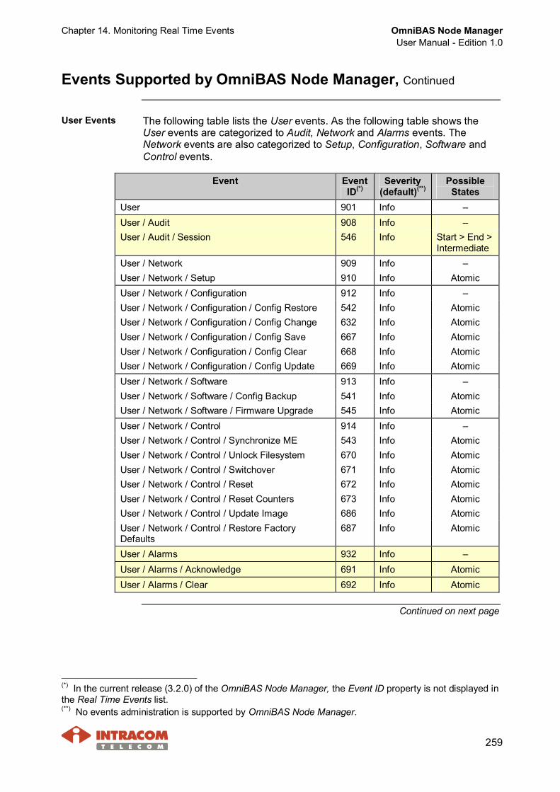
Chapter 14. Monitoring Real Time Events OmniBAS Node ManagerUser Manual - Edition 1.0
259
Events Supported by OmniBAS Node Manager, Continued
User Events The following table lists the User events. As the following table shows theUser events are categorized to Audit, Network and Alarms events. TheNetwork events are also categorized to Setup, Configuration, Software andControl events.
Event EventID(*)
Severity(default)(**)
PossibleStates
User 901 Info –User / Audit 908 Info –User / Audit / Session 546 Info Start > End >
IntermediateUser / Network 909 Info –User / Network / Setup 910 Info AtomicUser / Network / Configuration 912 Info –User / Network / Configuration / Config Restore 542 Info AtomicUser / Network / Configuration / Config Change 632 Info AtomicUser / Network / Configuration / Config Save 667 Info AtomicUser / Network / Configuration / Config Clear 668 Info AtomicUser / Network / Configuration / Config Update 669 Info AtomicUser / Network / Software 913 Info –User / Network / Software / Config Backup 541 Info AtomicUser / Network / Software / Firmware Upgrade 545 Info AtomicUser / Network / Control 914 Info –User / Network / Control / Synchronize ME 543 Info AtomicUser / Network / Control / Unlock Filesystem 670 Info AtomicUser / Network / Control / Switchover 671 Info AtomicUser / Network / Control / Reset 672 Info AtomicUser / Network / Control / Reset Counters 673 Info AtomicUser / Network / Control / Update Image 686 Info AtomicUser / Network / Control / Restore FactoryDefaults
687 Info Atomic
User / Alarms 932 Info –User / Alarms / Acknowledge 691 Info AtomicUser / Alarms / Clear 692 Info Atomic
Continued on next page
(*) In the current release (3.2.0) of the OmniBAS Node Manager, the Event ID property is not displayed inthe Real Time Events list.(**) No events administration is supported by OmniBAS Node Manager.
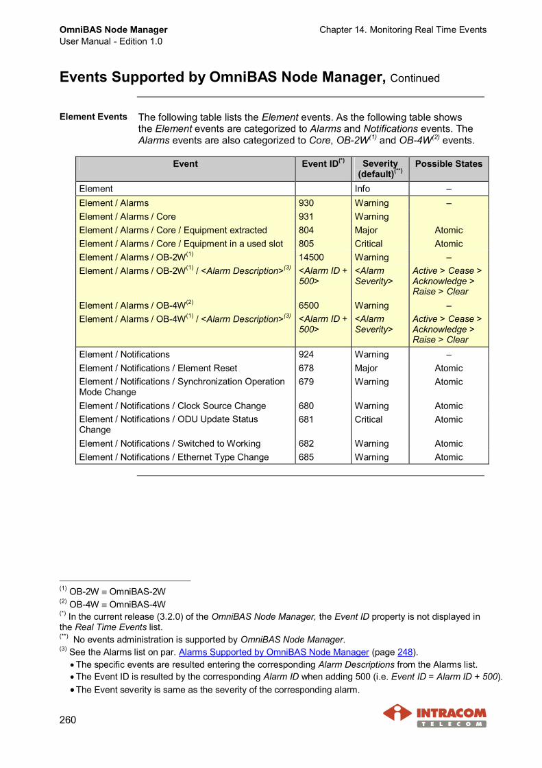
OmniBAS Node ManagerUser Manual - Edition 1.0
Chapter 14. Monitoring Real Time Events
260
Events Supported by OmniBAS Node Manager, Continued
Element Events The following table lists the Element events. As the following table showsthe Element events are categorized to Alarms and Notifications events. TheAlarms events are also categorized to Core, OB-2W(1) and OB-4W(2) events.
Event Event ID(*) Severity(default)(**)
Possible States
Element Info –Element / Alarms 930 Warning –Element / Alarms / Core 931 WarningElement / Alarms / Core / Equipment extracted 804 Major AtomicElement / Alarms / Core / Equipment in a used slot 805 Critical AtomicElement / Alarms / OB-2W(1) 14500 Warning –Element / Alarms / OB-2W(1) / <Alarm Description>(3) <Alarm ID +
500><AlarmSeverity>
Active > Cease >Acknowledge >Raise > Clear
Element / Alarms / OB-4W(2) 6500 Warning –Element / Alarms / OB-4W(1) / <Alarm Description>(3) <Alarm ID +
500><AlarmSeverity>
Active > Cease >Acknowledge >Raise > Clear
Element / Notifications 924 Warning –Element / Notifications / Element Reset 678 Major AtomicElement / Notifications / Synchronization OperationMode Change
679 Warning Atomic
Element / Notifications / Clock Source Change 680 Warning AtomicElement / Notifications / ODU Update StatusChange
681 Critical Atomic
Element / Notifications / Switched to Working 682 Warning AtomicElement / Notifications / Ethernet Type Change 685 Warning Atomic
(1) OB-2W º OmniBAS-2W(2) OB-4W º OmniBAS-4W(*) In the current release (3.2.0) of the OmniBAS Node Manager, the Event ID property is not displayed inthe Real Time Events list.(**) No events administration is supported by OmniBAS Node Manager.(3) See the Alarms list on par. Alarms Supported by OmniBAS Node Manager (page 248).
· The specific events are resulted entering the corresponding Alarm Descriptions from the Alarms list.· The Event ID is resulted by the corresponding Alarm ID when adding 500 (i.e. Event ID = Alarm ID + 500).·The Event severity is same as the severity of the corresponding alarm.

Appendix - IEEE 802.1q / ad Ethernet Frames OmniBAS Node ManagerUser Manual - Edition 1.0
261
Appendix - IEEE 802.1q / ad Ethernet Frames
Ethernet frame(IEEE 802.1q)
The following schematic shows a standard Ethernet frame according to IEEE802.1q specification.
Ethernet frame(IEEE 802.1ad)
The following schematic shows how an untagged frame is C-tagged (in case ofC-VLAN Bridging Mode) or S-tagged (in case of S-VLAN Bridging Mode)(according to IEEE 802.1ad specification).
Continued on next page
OmniBAS Node ManagerUser Manual - Edition 1.0
Appendix - IEEE 802.1q / ad Ethernet Frames
262
Appendix - IEEE 802.1q / ad Ethernet Frames, Continued
About VLANtags (IEEE802.1q / ad)
· Ether Type – Indicates that the frame is an IEEE 802.1q or IEEE 802.1adtagged frame and by default takes the 0x8100 value.
· Default Priority – Indicates the frame priority level from 0 (lowest) to 7(highest), allowing packets to be grouped into various classes of traffic (voice,video, data, etc).
· CFI (Canonical Format Indicator) – Indicates whether the MAC address is incanonical (CFI=1) or non-canonical format (CFI=0). It is always set to zero(1) forEthernet switches.
· Default VLAN ID – Indicates the VLAN to which the frame belongs. It takesvalues from 1 to 4094. Value 1, by default, is reserved for management.Value 0, means that the frame does not belong to any VLAN; in this case theframe is referred as priority tagged.
(1) CFI is used for compatibility reason between Ethernet type network and Token Ring type network. If aframe received at an Ethernet port has CFI=1, then that frame should not be forwarded as it is to anuntagged port.
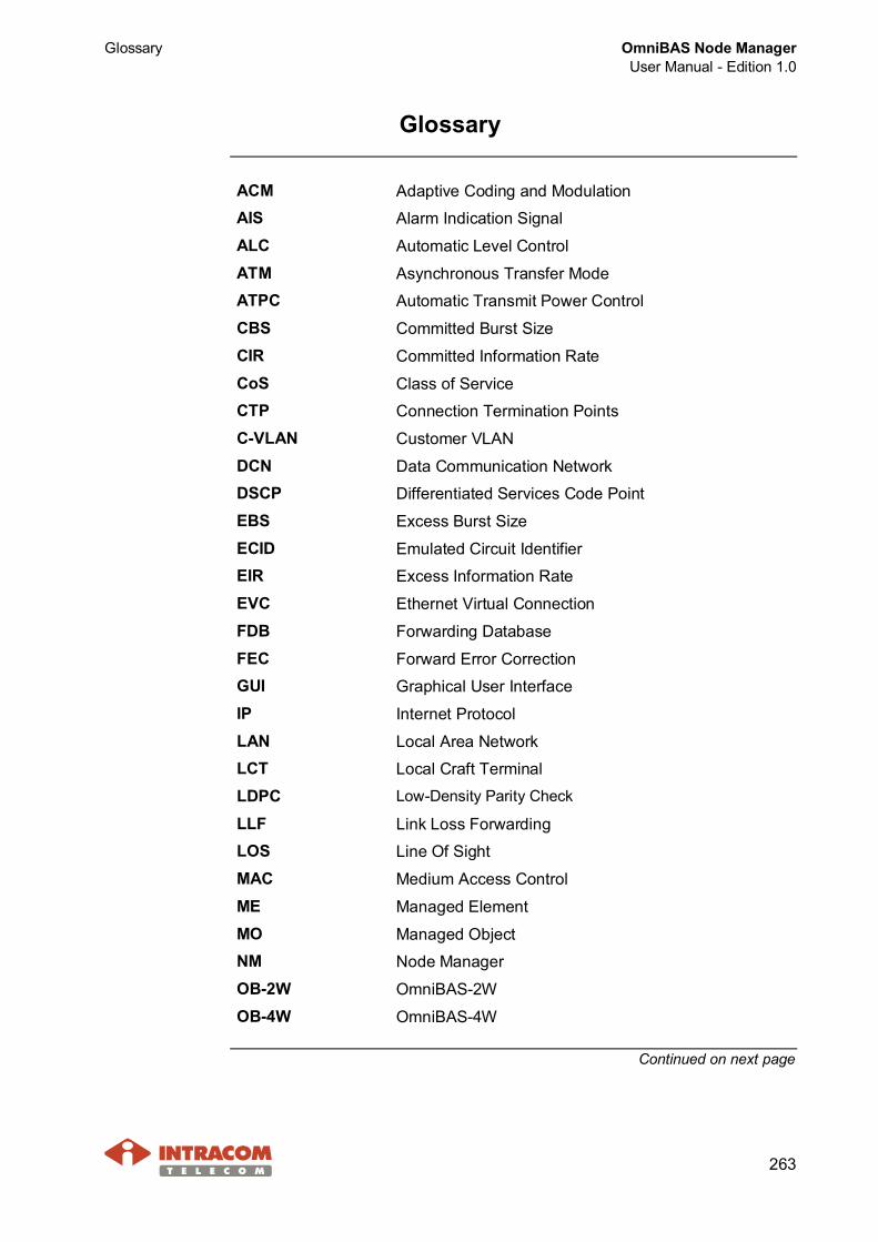
Glossary OmniBAS Node ManagerUser Manual - Edition 1.0
263
Glossary
ACM Adaptive Coding and ModulationAIS Alarm Indication Signal
ALC Automatic Level Control
ATM Asynchronous Transfer ModeATPC Automatic Transmit Power Control
CBS Committed Burst Size
CIR Committed Information Rate
CoS Class of ServiceCTP Connection Termination Points
C-VLAN Customer VLAN
DCN Data Communication NetworkDSCP Differentiated Services Code Point
EBS Excess Burst Size
ECID Emulated Circuit IdentifierEIR Excess Information Rate
EVC Ethernet Virtual Connection
FDB Forwarding Database
FEC Forward Error CorrectionGUI Graphical User Interface
IP Internet Protocol
LAN Local Area NetworkLCT Local Craft Terminal
LDPC Low-Density Parity Check
LLF Link Loss ForwardingLOS Line Of Sight
MAC Medium Access Control
ME Managed Element
MO Managed ObjectNM Node Manager
OB-2W OmniBAS-2W
OB-4W OmniBAS-4W
Continued on next page

OmniBAS Node ManagerUser Manual - Edition 1.0
Glossary
264
Glossary, Continued
ODU Outdoor UnitOOF Out of Frame
PLL Phase Locked Loop
PSN Packet Switched NetworkPSU Power Supply Unit
PtP (PTP) Point-to-Point
PWE Pseudo-Wire Emulation
QAM Quadrature Amplitude ModulationQoS Quality of Service
RAI Remote Alarm Indication
RSSI Receiver Signal Strength IndicatorSNC Sub-Network Connection
SNR Signal-to-Noise Ratio
S-VLAN Service VLANTCM Three Color Marking
TDM Time Division Multiplexing
TP Termination Point
UNI User-Network Interface
uni½MS Unified Management Suite
VLAN Virtual Local Area Network
WTR Wait-To-Restore


www.intracom-telecom.com
ISO 9001
BUREAU VERITASCertification
No GR14579Q
Europe
19.7 km. Markopoulou Ave., 19002 Peania, Athens Greece
tel.: +30 2106671000 fax: +30 2106671001 [email protected]
Russia & CIS
16 Krasnoproletarskaya Str., Bldg.1, Entr.3, Moscow, 127473 Russia
tel.: +7 495 921 4881 fax: +7 495 725 3805 [email protected]
Middle East & Africa
P.O. Box 500517, Dubai Internet City, Bldg.4, Office N°304, Dubai United Arab Emirates
tel.: +971 4 362 5666 fax: +971 4 390 4279 [email protected]
Asia-Pacific
9-10-11, GF, Augusta Point, Golf Course Road, Sector 53, Gurgaon HaryanaIndia
tel.: +91 124 4738500 fax: +91 124 4738555 [email protected]
America
11360 Technology Circle, Duluth, GA 30097USA
tel.: +1 770 295 2500 fax: +1 770 295 2600 [email protected]
All information contained in this document is subject to change without prior notice.© 2010 INTRACOM S.A. TELECOM SOLUTIONS
INTRACOM TELECOM Regional Contacts