Embed Size (px)
Citation preview
Page 1 of 15
Unifying Augmented Reality and Virtual Reality User Interfaces
Wayne Piekarski and Bruce H. Thomas
Wearable Computer Laboratory
School of Computer and Information Science
University of South Australia
Mawson Lakes, SA, 5095, Australia
{wayne, thomas}@cs.unisa.edu.au
Abstract
This paper presents a unified user interface technology, using 3D interaction techniques,
constructive solid geometry, and a glove based menuing system, known as Tinmith-Hand, to
support mobile outdoor augmented reality applications and indoor virtual reality applica-
tions. Tinmith-Hand uses similar concepts for both domains so that AR and VR applications
are consistent to use. The future goal of this user interface is to allow collaboration between
outdoor AR and indoor VR systems.
We use current AR and VR technology as a foundation for the user interface, and explain
several new techniques that we have devised that allow us to develop applications that allow
users to construct complex 3D models of objects in both indoor and outdoor settings. We
demonstrate our user interface with the capture of a large house at a distance outdoors, and
the creation of a simple building with street furniture at arms reach indoors.
1 Introduction
We have been investigating immersive 3D outdoor Augmented Reality (AR) architectures
and applications. One area we have investigated is the collaboration between a user outdoors
operating an AR application, while a second user is indoors in a Virtual Reality (VR) setting
[13]. We believe a unified user interface technology between outdoor AR and indoor VR ap-
plications is desirable to facilitate the interoperability between the systems.
Previously, we have demonstrated a mobile user of an AR system interacting with outdoor
3D entities, while another user interacts with the same entities on a VR workstation situated
indoors [13]. Both computer systems are in radio contact with each other to share information.
The mobile system transmits its position and orientation so that the VR system can draw an
avatar at the appropriate location on artificial terrain maps. Both the AR and VR users may
insert objects into the virtual world; these objects would appear overlaid on the AR user’s
outdoor view. Using the pitch, roll, and yaw of the outdoor user’s head, the presentation to the
indoor user of the virtual world can be slaved to the outdoor user’s direction of view. In other
words, we can provide a virtual camera without transmitting the raw video data. This original
system required two different sets of applications and user interfaces, one for indoors and one
for outdoors. It also only transmitted entity tracker information, not the actual models them-
selves, and only rendered points and labels for the AR user to simplify the display.
The goal of this investigation is to support collaboration between users in an indoor VR set-
ting, and mobile users outdoors viewing the same information with an AR interface. Imagine
someone is sent to a remote location to survey the physical terrain and building features; si-
Page 2 of 15
multaneously experts are viewing the data feed and directing the remote person’s actions. The
remote person is recording the surveyed information via a mobile AR computing system. The
indoor experts view the model as it is being built, and therefore the experts can direct the re-
mote users to regions of most interest by annotating the remote user’s view of the world.
In this paper we present one possible user interface for the two users, Tinmith-Hand, which
uses pinch gloves and thumb tracking to control a menu and a 3D modelling system. The an-
notation and communication aspects of the above scenario are currently being investigated.
The modelling and recording aspect has been demonstrated as two applications using the
Tinmith-Hand technology, Tinmith-Metro (an outdoor AR application) [15] and Tinmith-VR
(an indoor VR application). Tinmith-Metro allows users to capture the designs of outdoor
buildings and structures using special techniques that can be operated from a distance. Tin-
mith-VR is designed to model structures in the same fashion as Tinmith-Metro, but also al-
lows for direct manipulation operations that are within arms reach. Both modellers are based
around new techniques we have developed which rely on the intuitive nature of constructive
solid geometry (CSG) operations. The contribution of this work is the single user interface
technology to support interactive CSG modelling, as well as the way CSG is applied to cap-
ture outdoor 3D structures with AR, and create new models indoors with VR. Our work draws
heavily on known good solutions to AR and VR interaction problems, and it is through the
combination of these solutions that our technology has been developed.
The remainder of this section will discuss the aim of the user interface, as well as a sum-
mary of the concepts implemented. To place our work in context with that of other research-
ers, we provide an overview of related work that forms a foundation of our ideas. A descrip-
tion of our CSG technique is given, showing how buildings can be constructed from primitive
objects. We describe an example showing from a user’s perspective how Tinmith-Metro is
used to model a building in the outdoor augmented reality mode; and a second example creat-
ing an artificial scene using the indoor Tinmith-VR application. Our novel menuing system
with pinch gloves is discussed, followed by the use of thumb tracking, with image plane and
3D direct techniques for selection and manipulation of models. The overall implementation of
the system is also described, listing the hardware and software components used. We con-
clude this paper discussing some of the problems solved, the knowledge gained from this in-
vestigation, and future research.
1.1 Aims of the user interface
Our main interactions with Tinmith-Hand are through head and hand gestures (although
voice recognition is another viable option), and so we wish to keep the hands free from hold-
ing input devices if possible, allowing more natural styles of interaction. The primary user
interaction for graphical object manipulation will be through the 3D tracking of the user’s
head and two electronic pinch gloves. The gloves operating in a pinch mode will control the
menu system. The goal of the menu system is to allow the user to easily access the functional-
ity of the application, in a logical manner, while not obscuring the user’s vision or preventing
other tasks. When the entire system is combined together, Tinmith-Hand is a complete user
interface solution that is capable of controlling outdoor AR and indoor VR applications, in-
cluding 3D modelling.
1.2 Concepts implemented
The user operates the application with the Tinmith-Hand user interface, using head move-
ment, thumb tracking, pinch gloves, and a menu system to perform the following object ma-
nipulation tasks:
Page 3 of 15
Object selection – the user can point at objects and select them, placing them into one of
several clipboards.
Object transform – perform translate, rotate, and scale operations, in a variety of different
ways.
Create primitives – 3D primitives can be created in the virtual world, from infinite planes
as the simplest, to complex graphical models such as a water heater.
Combine primitives – previously constructed and manipulated primitives may be combined
together using Constructive Solid Geometry (CSG) operations to produce higher level
graphical objects.
The following components are used to implement the user interface and applications, used
to construct large graphical objects outdoors:
Menu system and pinch gloves – the command interface to the system through the pinch
action of our gloves. These gloves were custom built to integrate in with the rest of the
system.
Four integrated pointing techniques – the system is capable of using four interchangeable
pointing devices to supply input, depending on the requirements at the time and the suit-
ability. The devices are one and two handed thumb tracking, a head orientation eye cur-
sor, and a trackball mouse. Multiple selection buffers are used to store lists of objects in
the process of being constructed.
Image plane interaction techniques – these techniques are designed to support interactions
at a distance, where the objects are manipulated on a 2D plane perpendicular to the cur-
rent view direction [16]. By combining pointing with image plane techniques, it is possi-
ble to manipulate objects in a 3D environment, selecting an appropriate camera angle
simply by walking around in the physical world.
3D direct object manipulation – in immersive environments with objects that are within
arms reach, it is possible to manipulate an object directly in the same way that is done
with a physical object.
CSG operations – users intuitively understand operations such as carving and combining
objects. We have leveraged this understanding by basing the interactive construction of
complex real world shapes around the use of CSG operations.
2 Background
This section contains a brief overview of current AR and VR work, as well as other tech-
niques that can be used to capture the geometry of physical models.
2.1 Previous augmented reality systems
Most AR and VR systems are oriented toward information presentation, the user wearing a
HMD, moving around the world, and experiencing the artificial reality. There have been a
number of systems for outdoor augmented reality such as the MARS Touring machine [5],
NRL BARS system [8], previous UniSA Tinmith navigation systems [13, 22], and UniSA
ARquake [21]. However, these systems only allow the user to control the presentation of the
information, and not actually create new information, especially 3D models. An excellent dis-
cussion of other problems in the AR field is the survey paper in [1].
Page 4 of 15
2.2 Previous VR interaction work
There are a number of concepts we have leveraged from the area of VR interaction, al-
though most of these are focused on the manipulation of existing objects. As a result, the con-
struction of new objects from primitive building blocks is still a fruitful area of investigation.
Our system builds on concepts from a number of researchers, including: Proprioception and
the placement of objects relative to the body in [11]; Viewing and manipulation of objects us-
ing the Worlds-in-Miniature [20] and Voodoo Dolls [17] techniques; Two handed 3D interac-
tion techniques in [7] and [23]; Selection and manipulation techniques like the GoGo arm [18]
and various others covered in [2]; The WearTrack system and its variety of user interfaces in
[6].
Another existing powerful modelling system is MultiGen Smart Scene [12], which allows
users to construct and manipulate objects in a virtual environment using pinch gloves and di-
rect action with objects at arms reach.
Existing VR menu systems tend to be very similar to current desktop environments, in that
a tracker and button is used as a cursor to select from available options on a floating 3D tool-
bar or palette. Given that tracking technology has accuracy and delay problems, in some
cases, using these menus can be difficult and time consuming.
2.3 Current capturing techniques
There are a number of techniques to construct large outdoor graphical models. A simple
technique to model an existing building is to measure up and record the dimensions of an en-
tire building with a tape measure, for example. This is very inefficient and time consuming
because there may be inaccessible features, and the user must switch from indoors to outdoors
at each iteration to modify the model and then verify its accuracy. Faster methods such as la-
ser scanning and synthetic aperture radar [19], or multiple cameras [4], can be used to recover
models, but tend to have large quantities (sometimes millions) of wasteful facets, and suffer
from some features not being captured by the scans, causing ‘shadows’.
We propose our novel CSG primitive based approach as a way of interactively allowing us-
ers to build models outdoors, without the limitations of the other discussed methods. Al-
though there are other limitations introduced with this process, they are different from the
other two methods, and so the user now has an extra choice when deciding how to capture 3D
models. The method is designed to capture reasonably simple objects to the accuracy of the
tracking devices, and the user can create highly detailed models as they see fit, while keeping
others simple if desired.
3 Tinmith-Metro for outdoor AR modelling
To better understand our user interface technology, we explain our overall CSG modelling
technique and then present an example of how to construct a minimal graphical model of a
physical object in both AR and VR systems.
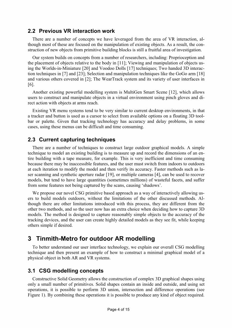
3.1 CSG modelling concepts
Constructive Solid Geometry allows the construction of complex 3D graphical shapes using
only a small number of primitives. Solid shapes contain an inside and outside, and using set
operations, it is possible to perform 3D union, intersection and difference operations (see
Figure 1). By combining these operations it is possible to produce any kind of object required.

Page 5 of 15
While mostly used on solid shapes, it is possible to also use infinite planes as primitives, with
a front and a back face defined by the surface normal. The region of space behind the back
face is defined to be ‘inside’ and hence if 6 planes are placed all perpendicular to each other,
an intersection operation will produce a solid 3D box with a finite inside area. Concave ob-
jects (such as T, L, or donut shapes) can be produced by subtracting one object away from
another.
Modelling systems tend to operate with finite objects that are directly manipulated by the
user at arms reach to form the object being constructed. However, in some cases, especially
when working with outdoor AR systems, it is not possible to interact directly with the object.
As a result, we propose the infinite planes technique – the user looks in the correct direction
and selects a menu option to create a plane of infinite length following the path created by fir-
ing a ray out of the eye. By walking around the object and looking along the lengths of the
walls defining an object, the user can define the bounding shape for a building without having
to make physical contact with it. As a result, it is possible to operate the system from large
distances away and still produce solid objects that match the physical world.
3.2 Tinmith-Metro outdoor AR example
The first example is of the Tinmith-Metro application being used outdoors to capture the
model of a simple house structure, with extra features such as indented windows, a sloped
roof, and outdoor accessories.
System start up - The user dons the backpack computer, pinch gloves, and HMD. The
HMD is then calibrated for the user’s head by capturing the orientation when they gaze level
to the north.
Create perimeter walls – The overall top down outline of the building must be specified to
partly define the solid house object. To create the outline, the user creates infinite planes to
mark each wall. Each plane is created by the following: 1) the user positions themselves to
look down the edge of a building wall, at any convenient distance, 2) the user places the eye
cursor along the wall edge, 3) the user selecting the menu option with the gloves to create a
right facing wall, and 4) the right facing wall (an infinite plane) is added to the virtual world
intersecting the eye cursor and perpendicular to the image plane. This wall cuts the entire in-
finite world in half, in the same way as the real wall does, with the left being inside the build-
ing, and the right being outside. By walking around the building and marking each plane, the
user is carving away sections of the infinite space and defining the volume of the building.
Eventually, when the user has completely circled the building, the 2D perimeter of the volume
is no longer infinite. The result is an approximate 2D bounded perimeter as shown from the
orbital person view in (1) of Figure 2. This figure shows some approximated finite planes that
are used to give the user an idea of the locations of the planes, although internally they are
stored as infinite plane equations.
Pyramid Sphere Union Intersection Difference
Figure 1 - CSG primitive operations example
Page 6 of 15
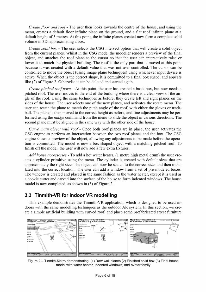
Create floor and roof - The user then looks towards the centre of the house, and using the
menu, creates a default floor infinite plane on the ground, and a flat roof infinite plane at a
default height of 3 metres. At this point, the infinite planes created now form a complete solid
volume in 3D, approximating a box.
Create solid box – The user selects the CSG intersect option that will create a solid object
from the current planes. Whilst in the CSG mode, the modeller renders a preview of the final
object, and attaches the roof plane to the cursor so that the user can interactively raise or
lower it to match the physical building. The roof is the only part that is moved at this point
because it was created with a default value that was not user controlled. The cursor can be
controlled to move the object (using image plane techniques) using whichever input device is
active. When the object is the correct shape, it is committed to a final box shape, and appears
like (2) of Figure 2. Otherwise it can be deleted and started again.
Create pitched roof parts - At this point, the user has created a basic box, but now needs a
pitched roof. The user moves to the end of the building where there is a clear view of the an-
gle of the roof. Using the same techniques as before, they create left and right planes on the
sides of the house. The user selects one of the new planes, and activates the rotate menu. The
user can rotate the plane to match the pitch angle of the roof, with either the gloves or track-
ball. The plane is then moved to the correct height as before, and fine adjustments may be per-
formed using the nudge command from the menu to slide the object in various directions. The
second plane must be aligned in the same way with the other side of the house.
Carve main object with roof - Once both roof planes are in place, the user activates the
CSG engine to perform an intersection between the two roof planes and the box. The CSG
engine shows a preview of the object, allowing any adjustments to be made before the opera-
tion is committed. The model is now a box shaped object with a matching pitched roof. To
finish off the model, the user will now add a few extra fixtures.
Add house accessories - To add a hot water heater, (1 metre high metal drum) the user cre-
ates a cylinder primitive using the menu. The cylinder is created with default sizes that are
approximately the right size. The object can now be scaled to the correct size, and then trans-
lated into the correct location. The user can add a window from a set of pre-modeled boxes.
The window is created and placed in the same fashion as the water heater, except it is used as
a cookie cutter and carved into the surface of the house to form indented windows. The house
model is now completed, as shown in (3) of Figure 2.
3.3 Tinmith-VR for indoor VR modelling
This example demonstrates the Tinmith-VR application, which is designed to be used in-
doors with the same modelling techniques as the outdoor AR system. In this section, we cre-
ate a simple artificial building with curved roof, and place some prefabricated street furniture
Figure 2 – Tinmith-Metro demonstrating: (1) Raw wall planes (2) Finished solid box (3) Final house model with water heater, indented windows, and avatar family
Page 7 of 15
items around it.
System start up – The user dons the pinch gloves and HMD, which are then calibrated for
the alignment of the user’s head.
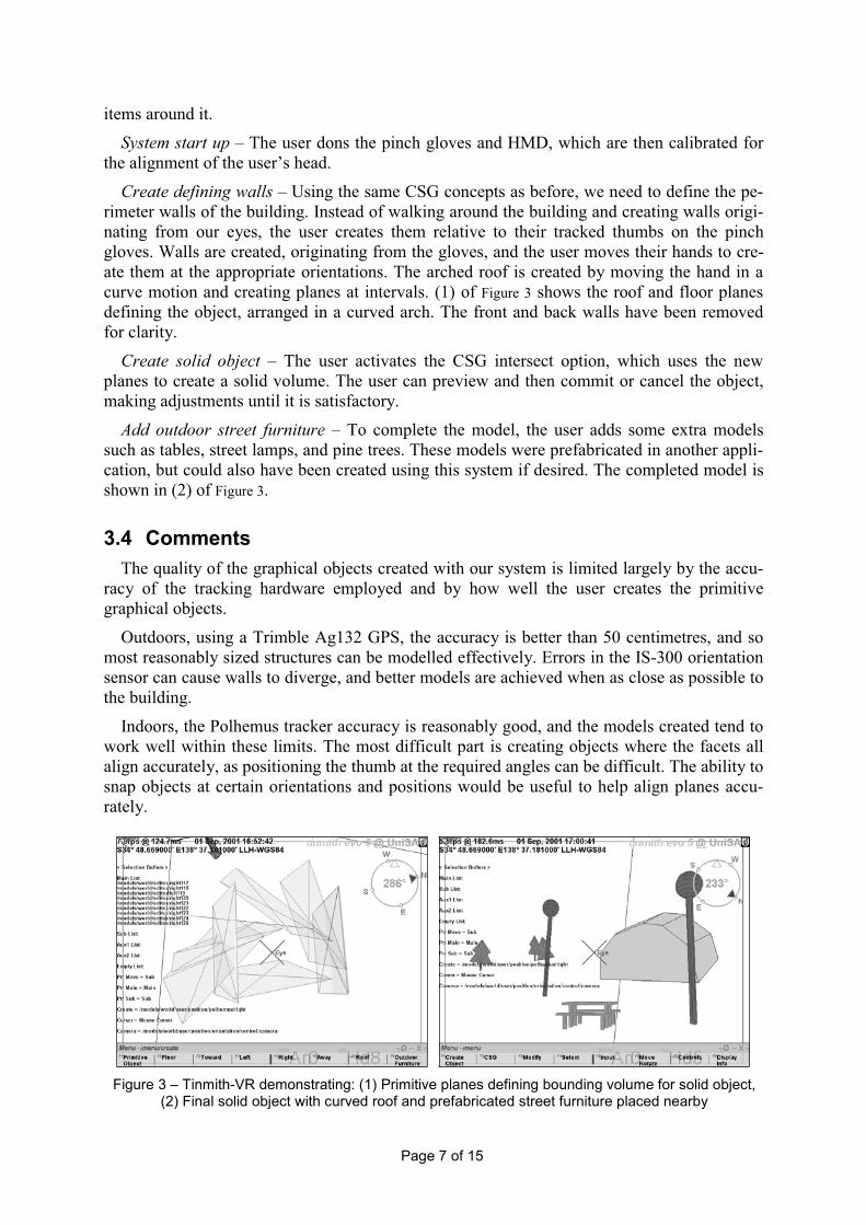
Create defining walls – Using the same CSG concepts as before, we need to define the pe-
rimeter walls of the building. Instead of walking around the building and creating walls origi-
nating from our eyes, the user creates them relative to their tracked thumbs on the pinch
gloves. Walls are created, originating from the gloves, and the user moves their hands to cre-
ate them at the appropriate orientations. The arched roof is created by moving the hand in a
curve motion and creating planes at intervals. (1) of Figure 3 shows the roof and floor planes
defining the object, arranged in a curved arch. The front and back walls have been removed
for clarity.
Create solid object – The user activates the CSG intersect option, which uses the new
planes to create a solid volume. The user can preview and then commit or cancel the object,
making adjustments until it is satisfactory.
Add outdoor street furniture – To complete the model, the user adds some extra models
such as tables, street lamps, and pine trees. These models were prefabricated in another appli-
cation, but could also have been created using this system if desired. The completed model is
shown in (2) of Figure 3.
3.4 Comments
The quality of the graphical objects created with our system is limited largely by the accu-
racy of the tracking hardware employed and by how well the user creates the primitive
graphical objects.
Outdoors, using a Trimble Ag132 GPS, the accuracy is better than 50 centimetres, and so
most reasonably sized structures can be modelled effectively. Errors in the IS-300 orientation
sensor can cause walls to diverge, and better models are achieved when as close as possible to
the building.
Indoors, the Polhemus tracker accuracy is reasonably good, and the models created tend to
work well within these limits. The most difficult part is creating objects where the facets all
align accurately, as positioning the thumb at the required angles can be difficult. The ability to
snap objects at certain orientations and positions would be useful to help align planes accu-
rately.
Figure 3 – Tinmith-VR demonstrating: (1) Primitive planes defining bounding volume for solid object, (2) Final solid object with curved roof and prefabricated street furniture placed nearby
Page 8 of 15
4 Menuing system
The menuing system of Tinmith-Hand is powerful enough to provide a user interface to a
fully functional 3D modelling system, supporting object hierarchies, CSG, and editable trans-
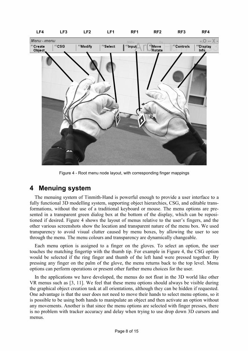
formations, without the use of a traditional keyboard or mouse. The menu options are pre-
sented in a transparent green dialog box at the bottom of the display, which can be reposi-
tioned if desired. Figure 4 shows the layout of menus relative to the user’s fingers, and the
other various screenshots show the location and transparent nature of the menu box. We used
transparency to avoid visual clutter caused by menu boxes, by allowing the user to see
through the menu. The menu colours and transparency are dynamically changeable.
Each menu option is assigned to a finger on the gloves. To select an option, the user
touches the matching fingertip with the thumb tip. For example in Figure 4, the CSG option
would be selected if the ring finger and thumb of the left hand were pressed together. By
pressing any finger on the palm of the glove, the menu returns back to the top level. Menu
options can perform operations or present other further menu choices for the user.
In the applications we have developed, the menus do not float in the 3D world like other
VR menus such as [3, 11]. We feel that these menu options should always be visible during
the graphical object creation task at all orientations, although they can be hidden if requested.
One advantage is that the user does not need to move their hands to select menu options, so it
is possible to be using both hands to manipulate an object and then activate an option without
any movements. Another is that since the menu options are selected with finger presses, there
is no problem with tracker accuracy and delay when trying to use drop down 3D cursors and
menus.
LF4 LF3 LF2 LF1 RF1 RF2 RF3 RF4
Figure 4 - Root menu node layout, with corresponding finger mappings
Page 9 of 15
The menu system described in [3] was developed at a similar time as ours for immersive
VR, although was different in that it was very much like traditional pull down menus. The
top-level menu items were available on one hand, and the second level options on the other
hand. Using the small finger it was possible to cycle through options if there were more than
three options. The menus were limited to a depth of two, and it is not scaleable to a large
number of hierarchical commands. Our system is fundamentally different since there is no
cycling through a small set of items, and an arbitrary depth of menus is possible.
5 Pointing and selection techniques
With Tinmith-Hand, the user has a choice of four input devices for pointing and selecting,
some are 2D, like the belt mounted trackball and eye cursor, while the thumb tracking is 3D
based. The user chooses whichever device is appropriate at the time for the particular control
or selection task. Traditional desktop applications only use one device, or merge the devices
to be all the same. All pointing and selection is currently performed using image plane tech-
niques, since most AR work involves working at a distance.
5.1 Hand based thumb tracking
Tinmith-Hand is designed to support applications that interact with graphical objects and
enter spatial information. We chose hand gestures to be the main interaction method for the
user interface. As previously mentioned, a set of pinch gloves are worn by the user, and Tin-
mith-Hand tracks the location of user’s two thumb tips.
Given the location of the thumbs, the system overlays registered 3D axes, as shown in
Figure 5. At the same time, a 2D flat cursor is overlaid on top. The cursor is placed in the de-
sired location by movement of the user’s hand. When the user activates selection mode using
the menu and gloves, a ray is fired into the scene from the 2D cursor, and the first object hit is
selected.
Why track the thumbs? We first thought of tracking the back of the user’s hand, but we
quickly realised that the hands easily fill up the user’s field of view when placing the cursor
within the field of view of the transparent AR display. It was decided that fingers would not
obscure the field of view as much and allow for finer motor control and larger movement. The
ends of the index fingers were dismissed as they moved too much during the selection of the
menu option with the index finger and thumb. We noticed that the thumb did not move much
during a pinching gesture however. People tended to bring their fingers down to meet their
thumb as opposed to bringing the thumb up to meet the fingers. As a result, we track the top
of the thumb. As another option, the index finger could be tracked for one handed cursor
movements, and the selection of the menus with the non-dominant hand.
5.2 Eye cursor
The eye cursor is fixed to the centre of the display, and is controlled by the user rotating
their head to point to different objects in the world. We have found the eye cursor to be very
useful during the construction of infinite wall planes in the outdoor AR application. The user
looks down the length of a physical wall and creates a virtual one that is coplanar. Objects
may also be selected with this mode, the user aims their head at the object, and the ray fired is
tested for intersecting objects.

Page 10 of 15
5.3 Object selection
When a user performs a pick operation on a graphical object, the system determines the
closest polygon under the cursor. When a polygon is selected, the simplest object is chosen,
but the user can traverse up the scene hierarchy to select more of the model if desired. Every
polygon and object in the scene exists in a searchable global model hierarchy.
5.4 Selection buffers
For CSG operations, users are required to select multiple objects, operate on them inde-
pendently, and then combine them together to produce a final object. One solution is to re-
peatedly select and deselect objects as required, but selection is tedious and error prone. As a
result, rather than having the ability to select just one object and operate on it, the user oper-
ates on collections of objects in the selection buffers, which are very similar to traditional
clipboards. In any particular selection buffer, the user may place multiple selected objects.
The user is able to switch between selection buffers and put different objects into different
buffers. CSG operations are performed between two selection buffers at a time. For example,
a user may intersect all the planes in buffers A and B while translating only the planes in
buffer B, the result going into A. Later, the user can place some different planes into buffer C,
rotate them, and then intersect them with the previously existing result (This is how the con-
struction of the pitched roof was performed in the example).
5.5 Camera controls
AR and VR systems are traditionally immersive, but there are situations where other cam-
era angles are appropriate and useful. For example, when viewing a large campus model, a
user may wish to view what is past the next building, or very far away – both of which are not
Figure 5 – 3D cursor mapped onto the vision tracked hand in outdoor AR scenario with Tinmith-Metro

Page 11 of 15
practical with an immersive view of the world.
Tinmith-Metro and Tinmith-VR, like their predecessor [13], support a top down map, pro-
viding the user with a gods-eye view of the world, looking down onto the Earth. As the user
rotates their head, the entire map rotates as well, with the user’s direction being toward the top
of the display.
A second useful camera control model supported is orbital mode, described in [10]. In our
implementation, the orientation of the head is used to orbit around the user’s avatar, showing
their location compared to other objects in the world from a different angle.
6 Manipulation techniques
Tinmith-Hand supports a number of image plane techniques for manipulating (move, ro-
tate, and scale) objects in the environment. These image plane techniques require an input
cursor via one of the four input devices (one and two handed thumb tracking, eye cursor, or
hand trackball) and a selection buffer to operate on. The user, via the menus, selects the de-
sired input device and the selection buffer.
6.1 Object movement
This mode allows the user to translate an object parallel to the plane of the user’s display,
and is initiated via a menu selection. The cursor can be moved using the hand gloves, eye, or
trackball. The system fires a ray through the cursor and intersects it against the object, calcu-
lating the Z distance, then as the cursor is moved, an appropriate translation is added to the
object so that it stays under the cursor during movement. The commit option is selected to
save the new position. In this mode, the object can only be moved in any direction perpen-
dicular to the camera direction, and hence the Z distance is maintained.
6.2 Object movement nudging
Tinmith-Hand supports precise small incremental translations. In this mode, the user can
slightly move an object (nudge) in any of six directions (up, down, left, right, toward, away)
in increments of one metre. The user can walk around the object and refine the location from
all angles until the object is satisfactory. The advantages to this mode are that we can perform
movements that are finer than our outdoor tracking hardware or distance to the object will al-
low. Future systems will support scale and rotate nudging.
6.3 Object rotation
Rotation requires two points to be defined to calculate the rotation as an angle offset be-
tween two points. Because we are implementing image plane techniques, two user-controlled
cursors are used to define a line, which then determines the angle offset. The rotation is done
perpendicular to the display plane.
Two handed rotation techniques may be applied when both hand based thumb trackers are
employed by the user. When the user selects this mode, the angle formed between the two
cursors determines the rotation of the object.
The eye cursor by itself cannot be used in this mode, but can be used in combination with
the handheld track ball. The track ball uses the eye cursor as its reference point, and so the
rotation is determined between the changing track ball cursor and fixed eye.
Page 12 of 15
6.4 Object scale
The object scale interaction technique is similar to the rotate mode in that two input cursors
are required, with the distance between the two used to scale the object in the same X and Y
directions of the image plane coordinate system. Objects could be scaled uniformly in all
three dimensions by applying the scaling factor proportional to the change in distance be-
tween the two cursors.
6.5 3D direct manipulation operations
When an object is within arms reach, manipulation of objects is much easier as the user can
select the object, and then rotate or translate it directly with their hands in the physical world.
This technique is not generally used in the AR system, as objects such as buildings are large
and physically prevent the manipulation of other features that are occluded.
7 Tinmith system
The Tinmith-Hand interface, and the Tinmith-Metro and Tinmith-VR applications are cre-
ated using the Tinmith-evo5 system. This architecture is covered in [14], and Tinmith-Metro
is discussed extensively in [15].
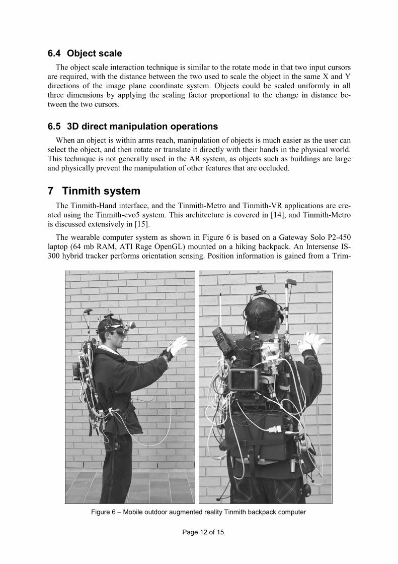
The wearable computer system as shown in Figure 6 is based on a Gateway Solo P2-450
laptop (64 mb RAM, ATI Rage OpenGL) mounted on a hiking backpack. An Intersense IS-
300 hybrid tracker performs orientation sensing. Position information is gained from a Trim-
Figure 6 – Mobile outdoor augmented reality Tinmith backpack computer

Page 13 of 15
ble Ag132 GPS, with an accuracy of 50 centimetres. The display is a Sony Glasstron PLM-
700e monocular SVGA display. A USB video camera is used to provide images for the thumb
tracking system. Custom made pinch gloves (shown in Figure 4), are combined with the target
tracking and used as the main input device. Fiducial markers placed on the thumbs are proc-
essed using the ARtoolkit software library [9], providing reasonable quality 6DOF tracking.
The indoor configuration uses the same hardware as above, except a Polhemus 6DOF mag-
netic tracker was used for both the head and thumbs, removing the need for the GPS, IS-300,
and video processing hardware. The operating range of the system was restricted to that of the
magnetic field of the fixed tracking hardware.
The laptop runs RedHat Linux 7.0 with kernel 2.4 as its operating system, including the
standard GNU development environment. XFree86 v3.3.6 is used for graphics, as it does
hardware accelerated OpenGL using Utah-GLX. The performance of the older ATI Rage
chipset is adequate for our current needs, as the system has low rendering requirements.
8 Conclusion
This paper has introduced the Tinmith-Hand AR/VR unified user interface, based on the
flexible Tinmith-evo5 software system. Using our modelling techniques, based on CSG,
tracked input gloves, image plane techniques, and a menu control system, it is possible to
build applications that can be used to construct complex 3D models of objects in both indoor
and outdoor settings.
As part of this work, we intend to explore various other 3D interaction techniques, and
other solid modelling concepts. Physical land features such as rivers and roads are currently
not simple to create, and other 3D techniques for action at a distance would be useful in im-
proving the selection and manipulation of objects. Finally, the main purpose of this work is to
form a foundation that can be used to extend the AR/VR integration work performed in [13],
producing a system which allows collaborative modelling between users in both outdoor AR
and indoor VR environments.
9 Acknowledgments
The authors would like to especially acknowledge the work of Arron and Spishek Piekar-
ski, who both helped in the construction and design of the glove and HMD. Thanks also to the
Division of ITEE and Defence Science Technology Organisation (DSTO).
10 References
[1] Azuma, R. A Survey of Augmented Reality. Presence: Teleoperators and Virtual Envi-
ronments, Vol. 6, No. 4, pp 355-385, Aug 1997.
[2] Bowman, D. A. and Hodges, L. F. An Evaluation of Techniques for Grabbing and Ma-
nipulating Remote Objects in Immersive Virtual Environments. In 1997 Symposium on
Interactive 3D Graphics, pp 35-38, Providence, RI, Apr 1997.
[3] Bowman, D. A. and Wingrave, C. A. Design and Evaluation of Menu Systems for Im-
mersive Virtual Environments. In IEEE Virtual Reality 2001, pp 149-156, Yokohama,
Japan, Mar 2001.
Page 14 of 15
[4] Debevec, P. E., Taylor, C. J., and Malik, J. Modeling and Rendering Architecture from
Photographs: A hybrid geometry- and image-based approach. In ACM SIGGRAPH 1996,
pp 11-20, New Orleans, LA, Aug 1996.
[5] Feiner, S., MacIntyre, B., and Hollerer, T. A Touring Machine: Prototyping 3D Mobile
Augmented Reality Systems for Exploring the Urban Environment. In 1st Int'l Sympo-
sium on Wearable Computers, pp 74-81, Cambridge, Ma, Oct 1997.
[6] Foxlin, E. and Harrington, M. WearTrack: A Self-Referenced Head and Hand Tracker for
Wearable Computers and Portable VR. In 4th Int'l Symposium on Wearable Computers,
pp 155-162, Atlanta, Ga, Oct 2000.
[7] Hinckley, K., Pausch, R., Goble, J. C., and Kassell, N. F. A Survey of Design Issues in
Spatial Input. In 7th Int'l Symposium on User Interface Software Technology, pp 213-
222, Marina del Rey, Ca, Nov 1994.
[8] Julier, S., Lanzagorta, M., Baillot, Y., Rosenblum, L., Feiner, S., and Hollerer, T. Infor-
mation Filtering for Mobile Augmented Reality. In 3rd Int'l Symposium on Augmented
Reality, pp 1-10, Munich, Germany, Oct 2000.
[9] Kato, H. and Billinghurst, M. Marker Tracking and HMD Calibration for a Video-based
Augmented Reality Conferencing System. In 2nd Int'l Workshop on Augmented Reality,
pp 85-94, San Francisco, Ca, Oct 1999.
[10] Koller, D. R., Mine, M. R., and Hudson, S. E. Head-Tracked Orbital Viewing: An Inter-
action Technique for Immersive Virtual Environments. In 9th Int'l Symposium on User
Interface Software Technology, pp 81-82, Seattle, Wa, Nov 1996.
[11] Mine, M., Brooks, F. P., and Sequin, C. H. Moving Objects In Space: Exploiting Proprio-
ception In Virtual-Environment Interaction. In ACM SIGGRAPH 1997, pp 19-26, Los
Angeles, Ca, Aug 1997.
[12] Multigen. SmartScene. URL - http://www.multigen.com
[13] Piekarski, W., Gunther, B., and Thomas, B. Integrating Virtual and Augmented Realities
in an Outdoor Application. In 2nd Int'l Workshop on Augmented Reality, pp 45-54, San
Francisco, Ca, Oct 1999.
[14] Piekarski, W. and Thomas, B. Tinmith-evo5 - An Architecture for Supporting Mobile
Augmented Reality Environments. In 2nd Int'l Symposium on Augmented Reality, pp
177-178, New York, NY, Oct 2001.
[15] Piekarski, W. and Thomas, B. Tinmith-Metro: New Outdoor Techniques for Creating
City Models with an Augmented Reality Wearable Computer. In 5th Int'l Symposium on
Wearable Computers, Zurich, Switzerland, Oct 2001.
[16] Pierce, J., Forsberg, A., Conway, M., Hong, S., Zeleznik, R., and Mine, M. Image Plane
Interaction Techniques in 3D Immersive Environments. In 1997 Symposium on Interac-
tive 3D Graphics, pp 39-43, Providence, RI, Apr 1997.
[17] Pierce, J. S., Steams, B. C., and Pausch, R. Voodoo Dolls: Seamless Interaction at Multi-
ple Scales in Virtual Environments. In 1999 Symposium on Interactive 3D Graphics, pp
141-145, Atlanta, Ga, Apr 1999.
[18] Poupyrev, I., Billinghurst, M., Weghorst, S., and Ichikawa, T. The Go-Go Interaction
Technique: Non-linear Mapping for Direct Manipulation in VR. In 9th Int'l Symposium
on User Interface Software Technology, pp 79-80, Seattle, WA, Nov 1996.
Page 15 of 15
[19] Sester, M., Brenner, C., and Haala, N. 3-D Virtual Cities and 3D Geospatial Information
Systems. In IMAGE2000 Workshop, Ipswich, Qld,
[20] Stoakley, R., Conway, M. J., and Pausch, R. Virtual Reality on a WIM: Interactive
Worlds in Miniature. In CHI 1995 - Conference on Human Factors in Computing Sys-
tems, pp 265-272, Denver, Co, May 1995.
[21] Thomas, B., Close, B., Donoghue, J., Squires, J., De Bondi, P., Morris, M., and Piekarski,
W. ARQuake: An Outdoor/Indoor Augmented Reality First Person Application. In 4th
Int'l Symposium on Wearable Computers, pp 139-146, Atlanta, Ga, Oct 2000.
[22] Thomas, B. H., Demczuk, V., Piekarski, W., Hepworth, D., and Gunther, D. A Wearable
Computer System With Augmented Reality to Support Terrestrial Navigation. In 2nd
Int'l Symposium on Wearable Computers, pp 168-171, Pittsburg, Pa, Oct 1998.
[23] Zeleznik, R. C., Forsberg, A. S., and Strauss, P. S. Two Pointer Input For 3D Interaction.
In 1997 Symposium on Interactive 3D Graphics, pp 115-120, Providence, RI, Apr 1997.


![Augmented Realitycourses.ischool.berkeley.edu/.../system/files/Augmented+Reality.pdf · Difference [nguyen, today, tuiClass] Both Tangible User Interface (TUI) and Augmented Reality](https://img.dokumen.tips/doc/110x75/5ab9bed87f8b9a28468e6d4d/augmented-realitypdfdifference-nguyen-today-tuiclass-both-tangible-user-interface.jpg)