Embed Size (px)
Citation preview

UFC 4-150-02 12 May 2003
UNIFIED FACILITIES CRITERIA (UFC)
DESIGN:
DOCKSIDE UTILITIES FOR SHIP SERVICE
APPROVED FOR PUBLIC RELEASE; DISTRIBUTION UNLIMITED
CANCELLED
UFC 4-150-02 12 May 2003
UNIFIED FACILITIES CRITERIA (UFC)
DESIGN: DOCKSIDE UTILITIES FOR SHIP SERVICE Any copyrighted material included in this UFC is identified at its point of use. Use of the copyrighted material apart from this UFC must have the permission of the copyright holder. U.S. ARMY CORPS OF ENGINEERS NAVAL FACILITIES ENGINEERING COMMAND (Preparing Activity) AIR FORCE CIVIL ENGINEER SUPPORT AGENCY Record of Changes (changes are indicated by \1\ ... /1/)
Change No. Date Location
This UFC supersedes Military Handbook 1025/2, Dockside Utilities for Ship Service dated May 1988.
CANCELLED
UFC 4-150-02 12 May 2003
FOREWORD
The Unified Facilities Criteria (UFC) system is prescribed by MIL-STD 3007 and provides planning, design, construction, sustainment, restoration, and modernization criteria, and applies to the Military Departments, the Defense Agencies, and the DoD Field Activities in accordance with USD(AT&L) Memorandum dated 29 May 2002. UFC will be used for all DoD projects and work for other customers where appropriate.
UFC are living documents and will be periodically reviewed, updated, and made available to users as part of the Services’ responsibility for providing technical criteria for military construction. Headquarters, U.S. Army Corps of Engineers (HQUSACE), Naval Facilities Engineering Command (NAVFAC), and Air Force Civil Engineer Support Agency (AFCESA) are responsible for administration of the UFC system. Defense agencies should contact the preparing service for document interpretation and improvements. Technical content of UFC is the responsibility of the cognizant DoD working group. Recommended changes with supporting rationale should be sent to the respective service proponent office by the following electronic form: Criteria Change Request (CCR). The form is also accessible from the Internet sites listed below.
UFC are effective upon issuance and are distributed only in electronic media from
the following sources:
• Unified Facilities Criteria (UFC) Index http://65.204.17.188//report/doc_ufc.html. • USACE TECHINFO Internet site http://www.hnd.usace.army.mil/techinfo/index.htm. • NAVFAC Engineering Innovation and Criteria Office Internet site http://criteria.navfac.navy.mil. • Construction Criteria Base (CCB) system maintained by the National Institute of Building Sciences
at Internet site http://www.nibs.org/ccb.
Hard copies of UFC printed from electronic media should be checked against the current electronic version prior to use to ensure that they are current.
AUTHORIZED BY: _Approved by Correspondence, May 2003_ Donald Basham, P.E. Chief, Engineering and Construction Division U.S. Army Corps of Engineers
______________________________________Dr. James W Wright, P.E. Chief Engineer Naval Facilities Engineering Command
______________________________________ Kathleen I Ferguson, P.E. The Deputy Civil Engineer DCS/Installations & Logistics Department of the Air Force
______________________________________Frank Lane Director of Analysis & Investment Deputy Under Secretary of Defense for Installations and Environment Department of Defense
CANCELLED

UFC 4-150-02 12 May 2003
i
CONTENTS
Page CHAPTER 1 INTRODUCTION Paragraph 1-1 PURPOSE ......................................................................................... 1-1 1-1.1 Ships Characteristics Database (SCDB.) .......................................... 1-1
1-2 U.S. ARMY REQUIREMENTS .......................................................... 1-1 1-3 BACKGROUND................................................................................. 1-1 1-3.1 General Information ........................................................................... 1-1
CHAPTER 2 REQUIREMENTS Paragraph 2-1 SHIPS DEMANDS ............................................................................. 2-1
2-2 UTILITY-CONNECTION LAYOUT..................................................... 2-1 2-2.1 Connection Grouping......................................................................... 2-1 2-2.2 Hose and Cable Length ..................................................................... 2-3 2-2.3 Group Locations and Spacing ........................................................... 2-3 2-3 UTILITY CONNECTION GROUP DESIGN ....................................... 2-4 2-3.1 Configuration to Avoid Interference ................................................... 2-4 2-3.2 Design for Nesting of Ships ............................................................... 2-4 2-4 PROTECTION ................................................................................... 2-8 2-4.1 Protection of Mains and Laterals ....................................................... 2-8 2-4.2 Protection of Utility Connections........................................................ 2-9 2-4.3 Seismic Protection ............................................................................. 2-9 2-4.4 Cathodic Protection Systems (CPS)..................................................2-11 2-5 METERING........................................................................................2-13 2-6 PAINT AND FINISH REQUIREMENTS.............................................2-14 2-7 UTILITY CONNECTIONS COLOR CODES ......................................2-14 2-8 DEPERMING PIERS NAD FACILITIES ............................................2-14
CHAPTER 3 ACTIVE AND REPAIR BERTHING Paragraph 3-1 STEAM SYSTEMS ............................................................................ 3-1
3-1.1 Demands ........................................................................................... 3-1 3-1.2 Size of Piping..................................................................................... 3-1 3-1.3 Piping System Design Criteria ........................................................... 3-1 3-1.4 Location and Arrangement of Piping Mains and Branches................ 3-4 3-1.5 Outlet Design ..................................................................................... 3-4 3-1.6 Specific Ship Requirements............................................................... 3-6 3-1.7 Shore-to-Ship Steam and Feedwater Requirements......................... 3-6 3-1.8 Metering............................................................................................. 3-8 3-2 COMPRESSED AIR SYSTEMS ........................................................ 3-8 3-2.1 Demands ........................................................................................... 3-8 3-2.2 Piping System Design Criteria ...........................................................3-10 3-2.3 Quality................................................................................................3-10 3-2.4 Size of Piping.....................................................................................3-10 3-2.5 Location and Arrangement of Piping Mains and Branches................3-11 3-2.6 Outlet Design .....................................................................................3-11 3-2.7 Requirements for High-Pressure Compressed Air ............................3-13 3-3 SALTWATER OR NONPOTABLE WATER SYSTEMS.....................3-13
CANCELLED

UFC 4-150-02 12 May 2003
ii
3-3.1 Justification ........................................................................................3-13 3-3.2 Demands and Pressure Requirements..............................................3-15 3-3.3 Pumping Equipment ..........................................................................3-16 3-3.4 Piping and Outlets .............................................................................3-18 3-3.5 CV, CVN, LHA, and LHD Requirements (All Classes) ......................3-19 3-3.6 Other Nuclear-Powered Ship Requirements .....................................3-21 3-4 POTABLE WATER SYSTEMS ..........................................................3-21 3-4.1 Quantity and Pressure Requirements................................................3-21 3-4.2 Piping System Design Criteria ...........................................................3-24 3-4.3 Location and Arrangement of Piping Mains.......................................3-24 3-4.4 Piping and Outlets .............................................................................3-24 3-4.5 Location and Spacing of Outlets........................................................3-26 3-4.6 Specific Ship Requirements...............................................................3-26 3-4.7 Quality................................................................................................3-26 3-4.8 Metering.............................................................................................3-26 3-5 POL SYSTEMS .................................................................................3-26 3-6 OILY WASTE SYSTEMS...................................................................3-27 3-6.1 Pierside and Barge Collection of Shipboard Oily Waste....................3-27 3-6.2 Ship Oily Waste Generation ..............................................................3-29 3-6.3 Pumping Equipment ..........................................................................3-29 3-6.4 Piping Systems ..................................................................................3-29 3-6.5 Metering.............................................................................................3-30 3-7 SEWAGE SYSTEMS.........................................................................3-30 3-7.1 Introduction ........................................................................................3-30 3-7.2 Specialized Shipboard Sewage Characteristics and Parameters......3-30 3-7.3 Pier and Wharf Systems ....................................................................3-34 3-7.4 Drydock Facilities...............................................................................3-50 3-8 ELECTRICAL SYSTEMS ..................................................................3-55 3-8.1 Types of Electrical Services...............................................................3-55 3-8.2 Primary Power System ......................................................................3-55 3-8.3 Secondary Power Systems................................................................3-56 3-8.4 Location and Arrangement of Equipment ..........................................3-57 3-8.5 Distribution System Equipment and Materials ...................................3-60 3-8.6 Ships’ Shore Power Requirements....................................................3-63 3-8.7 Supplemental Requirements for Nuclear Submarines (SSN, SSBN) 3-64 3-8.8 Ground System..................................................................................3-65 3-8.9 Pier Lighting.......................................................................................3-65 3-9 TELECOMMUNICATION SYSTEMS ................................................3-66 3-9.1 BLII Pier Connectivity ........................................................................3-66 3-9.2 Telephone Systems ...........................................................................3-67 3-9.3 Other Telecommunications Systems .................................................3-67 3-10 PIER POWER METERING SYSTEMS..............................................3-68 3-10.1 Pier Power Monitoring System (PPMS).............................................3-68 3-11 OTHER SERVICES...........................................................................3-69
CHAPTER 4 SUPPLY AND AMMUNITION PIERS Paragraph 4-1 STEAM AND COMPRESSED AIR .................................................... 4-1
4-2 SALTWATER AND NONPOTABLE WATER..................................... 4-1 4-3 POTABLE WATER, SEWER AND OILY WASTE ............................. 4-1 4-4 ELECTRICAL SERVICE.................................................................... 4-1 4-5 TELECOMMUNICATION SYSTEMS ................................................ 4-1
CANCELLED
UFC 4-150-02 12 May 2003
iii
CHAPTER 5 FUELING PIERS Paragraph 5-1 STEAM AND COMPRESSED AIR .................................................... 5-1
5-2 SALTWATER AND NONPOTABLE WATER..................................... 5-1 5-3 POTABLE WATER, SEWER AND OILY WASTE ............................. 5-1 5-4 POL SYSTEMS ................................................................................. 5-1 5-5 ELECTRICAL SYSTEMS .................................................................. 5-1 5-6 TELECOMMUNCIATON SYSTEMS ................................................. 5-1 5-7 ADDITIONAL REQUIREMENTS ....................................................... 5-1 5-8 FIRE PROTECTION.......................................................................... 5-1
CHAPTER 6 MISCELLANEOUS PROVISIONS Paragraph 6-1 FREEZE PROTECTION .................................................................... 6-1
6-1.1 Where Required................................................................................. 6-1 6-1.2 Regional Weather Differences........................................................... 6-1 6-1.3 Methods ............................................................................................. 6-1 6-1.4 Protection in Regions I and II............................................................. 6-1 6-1.5 Protection in Regions III and IV ......................................................... 6-2 6-1.6 Protection in Region V ....................................................................... 6-3 6-1.7 Modifications of Requirements for Saltwater ..................................... 6-3 6-1.8 Materials ............................................................................................ 6-3 6-2 PIPING IDENTIFICATION ................................................................. 6-4 6-2.1 Primary Identification ......................................................................... 6-4 6-2.2 Color-Coding...................................................................................... 6-4 6-3 OPERATIONAL NOTICES ................................................................ 6-4
CHAPTER 7 U.S. ARMY REQUIREMENTS Paragraph 7-1 APPLICABILITY................................................................................. 7-1 7-2 POTABLE WATER ............................................................................ 7-1
7-2.1 Quantity and Pressure Requirement ................................................. 7-1 7-2.2 Piping Outlets .................................................................................... 7-1 7-3 ELECTRIC POWER .......................................................................... 7-1 7-3.1 Electrical System Characteristics ...................................................... 7-1 7-3.2 Ground System.................................................................................. 7-1 7-4 LOCATION AND NUMBER OF SERVICE POINTS .......................... 7-1 7-5 MISCELLANEOUS ............................................................................ 7-3 7-5.1 Telephone Service............................................................................. 7-3 7-5.2 Lighting .............................................................................................. 7-3 7-5.3 Fire Protection ................................................................................... 7-3 7-5.4 Sanitary Facilities and Sewage Disposal........................................... 7-3
APPENDIX A REFERENCES........................................................................ A-1 APPENDIX B GLOSSARY.............................................................................B-1 APPENDIX C CLIMATOLOGICAL DATA ......................................................C-1 APPENDIX D TYPICAL ELECTRICAL DIAGRAMS AND DETAILS ..............D-1
CANCELLED
UFC 4-150-02 12 May 2003
iv
FIGURES Figure Title 2-1 Typical Ship-Berth-Pier-Utilities Relationships .......................................... 2-2 2-2A Double-Deck Pier Example (1 of 3)........................................................... 2-5 2-2B Double-Deck Pier Example (2 of 3)........................................................... 2-6 2-2C Double-Deck Pier Example (3 of 3)........................................................... 2-7 3-1 Typical Steam Outlet Assembly ................................................................ 3-5 3-2 Schematic Steam Separator and Sampling Station .................................. 3-9 3-3 Typical Compressed Air Outlet Assembly ................................................. 3-12 3-4 Typical Salt Non-Potable Water Outlet Assembly ..................................... 3-20 3-5 International Shore Connection for Ship Fire Mains.................................. 3-22 3-6 Salt or Non-Potable Water for CV, CVN Classes at Pier........................... 3-23 3-7 Typical Potable Water Outlet Assembly .................................................... 3-25 3-8 Ship-to-Shore Oily Waste Hose Connection ............................................. 3-28 3-9 Pressure Manifold Schematic for Pier and Wharf Systems....................... 3-35 3-10A Sewer Layout for Alternative Pier Types (1 of 2)....................................... 3-36 3-10B Sewer Layout for Alternative Pier Types (2 of 2)....................................... 3-37 3-11A Typical Sewage Collection Facilities (1 of 2) ............................................. 3-39 3-11B Typical Sewage Collection Facilities (2 of 2) ............................................. 3-40 3-12A Details for Sewage Collection Facilities (1 of 2) ........................................ 3-41 3-12B Details for Sewage Collection Facilities (2 of 2) ........................................ 3-42 3-13A Piping Details for Sewage Collection Facilities (1 of 2) ............................. 3-43 3-13B Piping Details for Sewage Collection Facilities (2 of 2) ............................. 3-44 3-14 Ship-to-Shore Sewage Hose Components................................................ 3-46 3-15 Above Pier hose Connection..................................................................... 3-47 3-16A Typical Sewage System Layouts for Drydock Facilities (1 of 2) ................ 3-51 3-16B Typical Sewage System Layouts for Drydock Facilities (2 of 2) ................ 3-52 3-17A Underground Hose Connection (1 of 2) .................................................... 3-53 3-17B Underground Hose Connection (2 of 2) .................................................... 3-54 3-18 Typical Alternative Pier Electrical Equipment Arrangements..................... 3-58 3-19 Block Diagram of Pier Structure ................................................................ 3-70 3-20 Pier Fiber Distribution Center .................................................................... 3-71 3-21 Pier Fiber Distribution EDC 1Rear Detail Surface Pier.............................. 3-72 3-22 Pier Fiber Distribution Center EDC 1 Rear Detail Submarine Pier ............ 3-73 3-23 Pier Fiber Distribution Center EDC 1 Front Detail Surface Pier ................ 3-74 3-24 Pier Fiber Distribution Center EDC 1 Front Detail Submarine Pier ........... 3-75 3-25 Fiber Optic Connectivity Riser Panel Detail............................................... 3-76 3-26 EDC Fiber Optic Patch Panel Surface Pier ............................................... 3-77 3-27 EDC Fiber Optic Patch Panel submarine Pier........................................... 3-78 3-28 Rubber Gasket Cutout Surface Pier.......................................................... 3-79 3-29 Rubber Gasket Cutout Submarine Pier ..................................................... 3-80 7-1 Typical Water Supply Connection for and Army Pier ................................ 7-2 C-1 U.S. Winter Weather Severity by Region .................................................. C-2 D-1A Electrical System for a Double-Deck Pier (1 of 9) ..................................... D-2 D-1B Electrical System for a Double-Deck Pier (2 of 9) ..................................... D-3
CANCELLED
UFC 4-150-02 12 May 2003
v
D-1C Electrical System for a Double-Deck Pier (3 of 9) ..................................... D-4 D-1D Electrical System for a Double-Deck Pier (4 of 9) ..................................... D-5 D-1E Electrical System for a Double-Deck Pier (5 of 9) ..................................... D-6 D-1F Electrical System for a Double-Deck Pier (6 of 9) ..................................... D-7 D-1G Electrical System for a Double-Deck Pier (7 of 9) ..................................... D-8 D-1H Electrical System for a Double-Deck Pier (8 of 9) ..................................... D-9 D-1I Electrical System for a Double-Deck Pier (9 of 9) ..................................... D-10 D-2A Pier Electrical Distribution: Typical Vault System (1 of 5).......................... D-11 D-2B Pier Electrical Distribution: Typical Vault System (2 of 5).......................... D-12 D-2C Pier Electrical Distribution: Typical Vault System (3 of 5).......................... D-13 D-2D Pier Electrical Distribution: Typical Vault System (4 of 5).......................... D-14 D-2E Pier Electrical Distribution: Vault Ventilation and Drainage (5 of 5)........... D-15 D-3A Portable Substation (1 of 3)....................................................................... D-16 D-3B Portable Substation (2 of 3)....................................................................... D-17 D-3C Portable Substation (3 of 3)....................................................................... D-18 D-4A Ship Service Outlet Assembly (1 of 2)....................................................... D-19 D-4B Ship Service Outlet Assembly (2 of 2)....................................................... D-20 D-5A Pier Electrical Distribution for Temporary Services (1 of 3) ....................... D-21 D-5B Pier Electrical Distribution for Temporary Services (2 of 3) ....................... D-22 D-5C Pier Electrical Distribution for Temporary Services (3 of 3) ....................... D-23
TABLES Table Title 3-1 Diversity Factors (DF) for Steam Usage...................................................... 3-2 3-1 (Continued) Shore Service – Steam Table............................................................ 3-3 3-2 Shore Steam and Condensed Shore Steam Quality Requirements............ 3-7 3-3 Bulk Shore Feedwater Quality Requirements ............................................. 3-7 3-4 Typical Ship Sewage Concentrations....................................................... 3-33 3-5 Chloride Inhibition of Biological Nitrification.............................................. 3-33 3-6 Special Pier Structures and Appurtenances............................................. 3-48 6-1 Color Code for Shore-to-Ship Utility Connections .................................... 6-5 C-1 Regional Weather Data............................................................................ C-3 C-2 Freeze Protection by Insulation and Heating: Suggested Combinations for
Regions I and II ........................................................................................ C-3 C-3 Freeze Protection by Insulation and Heating: Suggested Combinations for
Regions III and IV..................................................................................... C-4 C-4 Freeze Protection by Insulation and Heating: Suggested Combinations for
Region V .................................................................................................. C-4
CANCELLED

UFC 4-150-02 12 May 2003
1-1
CHAPTER 1
INTRODUCTION
1-1 PURPOSE. This UFC provides design criteria and guidance in the design of utility systems for piers, wharves, and drydocks. Criteria are given for Type I Piers (Fueling, Ammunition, and Supply); Type II Piers (General Purpose Piers); and Type III Piers (Repair Piers.) Utilities covered include steam, compressed air, salt or non-potable water, potable water, oily waste/waste oil (OWWO) or petroleum, oil and lubricants (POL), CHT, electric power, and telecommunications.
1-1.1 Ships Characteristics Database (SCDB). WATERS Toolbox, a selection of electronic tools available from the NAVFAC Engineering Innovation and Criteria Office (EICO), includes a Ships Characteristics Database (SCDB.) WATERS Toolbox can be downloaded from the EICO web site at http://criteria.navfac.navy.mil, or the Construction Criteria Base web site (www.ccb.org.) SCDB is an ACCESS database of Navy ship information. For information about USACE vessels, use the requirements for a similar Navy vessel or contact the cognizant USACE DISTRICT.
1-2 U.S. ARMY REQUIREMENTS. U.S. Army vessel requirements for dockside utilities are contained in Chapter 7.
1-3 BACKGROUND
1-3.1 General Information. This UFC has been developed from an evaluation of facilities in the shore establishment, from surveys of the availability of new materials and construction methods, and from selection of the best design practices of the Naval Facilities Engineering Command (NAVFACENGCOM), other Government agencies, and the private sector. This UFC was prepared using, to the maximum extent feasible, national professional society, association, and institute standards. Deviations from this criteria, in the planning, engineering, design, and construction of naval shore facilities, cannot be made without prior approval of NAVFAC EICO or USACE.
CANCELLED
UFC 4-150-02 12 May 2003
2-1
CHAPTER 2
GENERAL UTILITY REQUIREMENTS
2-1 SHIPS DEMANDS. Ships utility demands and other pertinent data for individual ships utilities are available from SCDB (see paragraph 1-1.2.) The designer must access this information in order to obtain the latest design data regarding dockside utilities for all ship services. In general, ship utility demands for active berthing are based on the ship's complement without deployed forces such as air wings or marine troops. Diversity factors are provided for use in determining demand in multiple berthing. If the designer is basing the project design on a specific ship that is not included in SCDB, use data from a similar ship, or obtain the expected demand from NAVFAC EICO or USACE. For graving drydocks, refer to UFC 4-213-10. This information is for use at new facilities and for use in additions, modifications, and replacements at existing facilities. While means of diversification are provided for multiple ships and multiple piers by these diversity factors, metered data from existing facilities and ships should be used for planning and design whenever such data are available.
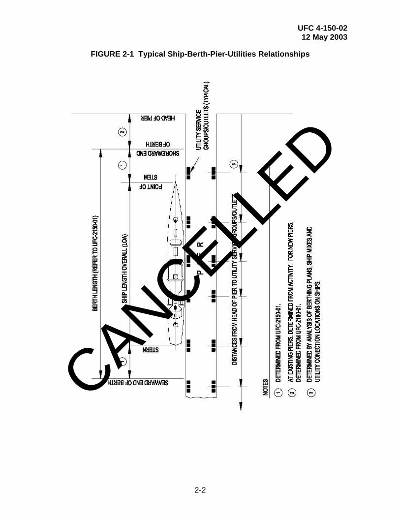
2-2 UTILITY-CONNECTION LAYOUT. Figure 2-1 shows the dimensional relationships normally encountered in placement of shore utility connections. SCDB provides size/shape data for typical ship hulls and dimensioned reference points that define the ship's utility connection locations. Ideally, the locations of shore utility connections for a given berth would simply correspond to their respective connection locations on the ship to be berthed. In practice, however, utility-connection locations can never be ideal, due to largely nondedicated berthing, interference with other pier or wharf activities, other deck equipment, and the grouping of connections. The designer must optimize the location of all utility outlet assemblies based upon the projected berthing mix.
2-2.1 Connection Grouping. Utility connections should be confined to specific locations along a shore facility so that interference with line handling and other facility operations is reduced. Connections may be in large groups to encompass all utilities, or may be in subgroups, such as the following:
• Freshwater, saltwater (if required), steam, and compressed air;
• Electrical power and communications;
• Sewer and oily waste; and
• POL, when required.
CANCELLED
UFC 4-150-02 12 May 2003
2-2
FIGURE 2-1 Typical Ship-Berth-Pier-Utilities Relationships
CANCELLED

UFC 4-150-02 12 May 2003
2-3
Regardless of the variations in utility groups that may be necessary to accommodate deck fittings and pier construction, sewer and oily waste connections must always be located 3.05 m (10 feet) or more from domestic water connections. Electrical outlet assemblies must be separated from other utility outlets by at least 10 feet (3.05 m) whenever possible. Additionally, where fueling is required, separation between such connections and electrical equipment is mandatory. See MIL-HDBK-1022A, Petroleum Fuel Facilities and consult with the cognizant Fire Protection Engineer to ascertain the minimum separation distances. Separation distances will vary depending upon the type of fuel or fuels.
2-2.2 Hose and Cable Lengths. Experience has shown that if utilities are to be grouped, not all of the shore connections can be placed optimally in regard to their respective ship connections, even at a dedicated berth. This being the case, the location of connections for certain utilities should be given preference in order to minimize required hose lengths. Preference should be given, in order of importance, to electrical power, fire protection water (if required), steam, sewage, oily waste collection, and potable water. Excessive hose and cable lengths have significant disadvantages as defined below.
2-2.2.1 Electrical Power. Excessive lengths of power cable increase the possibilities of accident, fire, and excessive voltage drop.
2-2.2.2 Fire Protection Water. Losses in the fire protection system hoses could be critical in the event of fire, particularly when ship's pumps are under repair.
2-2.2.3 Steam. Steam hoses have a very short life, are expensive, and usually have high-pressure losses from shore to ship.
2-2.2.4 Sewage. Although added hose pressure loss is not normally a problem, sewage hose is heavy, difficult to support, and must be disinfected when the ship's connection is broken.
2-2.3 Group Locations and Spacing. The locating dimensions for shipboard utility connections of various ship classes are presented in SCDB. These dimensions, when used with the ships configuration drawings and the parameters given in this UFC, provide guidance in spacing determinations for the shore connections. The locations of required deck equipment (capstans, bollards, cleats, ladders, and railings) and deck operations (brows, cranes, dumpsters, etc.) must always be coordinated with locations of utility connections. Pier berthing plans (graphic plots) must be made for the most likely ship mixes, and should consider local berthing practices as defined by the Activity. The berthing plans provide the basis for the design and operations of the pier's utility systems and must be included in the construction contract drawings when included under the design contract. Suitable shore connection spacing for the range of possible ships must be provided. Individual utilities within groups for mixed berthing should generally not be more than 66 m (200 ft) apart. Whenever possible, shore utility connection spacing should be such that connections are not offset more than 15.24 m
CANCELLED

UFC 4-150-02 12 May 2003
2-4
(50 ft) from corresponding ships connections when other ship types occupy their prescribed berths.
2-3 UTILITY CONNECTION GROUP DESIGN
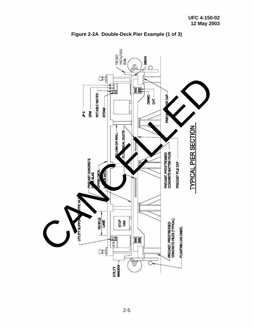
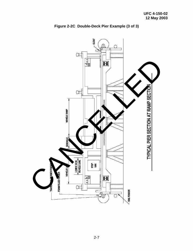
2-3.1 Configurations To Avoid Interference. Utility outlet groups should be designed for minimum interference of hoses and cables with each other, with deck equipment, and with deck operations. Check weights of hose lengths and cables with crane’s lifting capability. Outlet groups may be placed above deck or in deck pits. They may also be placed in open galleries below the main deck where the pier has sufficient elevation to avoid submergence of the utility connections. An example is a double-deck pier system such as Pier 6 at Naval Station Norfolk as shown in Figure 2-2. In order to avoid hose-connection difficulties and interferences with pier traffic, outlet connections should have centerlines parallel with berths or at not more than a 30-degree angle. The distance of connections from the pier face should be as short as is consistent with structural restraints and with convenience. However, on some aircraft carrier berths such as those using narrow breasting camels, locate the utilities to clear ship elevators. The type of connector at outlets must be compatible with hoses in use, or intended for use, at a given site. It is noted that the profile presented by utility groups above deck is dependent upon the height of the pier and the type of ship at berth. This is an important consideration in the design of dockside utilities for ship service. Mooring lines for ships such as destroyers are relatively low and present a greater hazard to utility connections. Low-profile utility outlet arrangements are usually preferred. Whenever possible, mooring line patterns for the specific ships to be berthed should be observed at a similar berth before utility group design is commenced. The berthing plans are to include mooring line patterns and must uncover conflicts with utility outlets. Some typical above-deck utility connection details are shown in figures in subsequent chapters. Other arrangements are also possible and may be acceptable. A specific arrangement may be required by the cognizant NAVFAC EFD/EFA or USACE DISTRICT to match existing outlet designs. Required hose or cable connection types and sizes are given in individual utility descriptions in the following chapters. Provide for future expansion of utilities by the appropriate sizing of valve pits, pipe trenches, electrical vaults, and electrical duct banks. Likewise, a specific project may require the immediate design for future utility services. Lastly, always design for proper and safe access and maintenance of all utility systems.
2-3.2 Design for Nesting of Ships. Where berthing plans include the nesting of ships, provide a sufficient quantity of adequately sized services and connections. Design according to the number of ships that may simultaneously use each such berth. Unless instructed otherwise, provide internal shipboard port-to-starboard utility headers for all utilities except for potable water. For potable water, use dual connections with individual backflow devices to provide separately protected supplies to two ships at each group location.
CANCELLED
UFC 4-150-02 12 May 2003
2-5
Figure 2-2A Double-Deck Pier Example (1 of 3)
CANCELLED

UFC 4-150-02 12 May 2003
2-6
Figure 2-2B Double-Deck Pier Example (2 of 3)
CANCELLED
UFC 4-150-02 12 May 2003
2-7
Figure 2-2C Double-Deck Pier Example (3 of 3)
CANCELLED

UFC 4-150-02 12 May 2003
2-8
2-4 PROTECTION
2-4.1 Protection of Mains and Laterals. Mains and laterals serving utility connections must be protected from damage by waves, wind, floating debris or ice, and tidal immersion. Where these lines could be subjected to such damage, they must be placed in the utility corridor of a double deck pier, place in the trenches or tunnels of a single deck pier, or special construction techniques must be used to provide a barrier. Electrical conduits may be embedded in new concrete structures. It is preferable to place electrical duct banks, manholes, and pull boxes such that they are cast integrally with the pier deck and at least 0.6 m (2 ft) above the mean high water level. There are cases where conduit and piping mains and laterals (except for POL systems) may be hung exposed from the bottom of pier decks in protected locations. This is not a preferred situation and is discouraged. In such cases, it is necessary to coordinate with the structural design to secure inspection ladders and deck inserts, and to facilitate installation of access platforms for maintenance purposes. New mains placed on existing piers may be placed on top of the pier deck if other construction techniques are impractical and if approved by the cognizant NAVFAC EFD/EFA OR USACE DISTRICT. However, the use of utility trenches is highly preferred. Trench covers may be concrete, steel plate, grating, or a combination of these, and as dictated by structural loading, maintenance, and cost considerations. Coordinate design with structural requirements. Note that permanently fixed covers (concrete and steel) create confined workspaces. This is a significant operational problem (regarding inspection and maintenance) that is generally undesirable and should be avoided if possible. Identifiable markings should be located on the trench entrances. Corrosion protection requirements are defined in the following paragraphs. Requirements for POL systems are defined in paragraph 3-5 and refer to MIL-HDBK-1022A, Petroleum Fuel Facilities.
2-4.1.1 Above-deck Lines. At most types of berthing facilities, clear deck space is at a premium, rendering above-deck mounting of utility services inappropriate, operationally difficult, and generally unacceptable. A notable exception to this general rule applies to dedicated fueling facilities. In these cases, above-deck mounting of fuel lines is often the most functional solution because it allows for the proper and safe access and maintenance of the fuel lines. See MIL-HDBK-1022A for additional information and criteria.
2-4.1.2 Under-deck Lines. Except as noted above, utility service pipelines should be not be located on the operating deck. At single deck piers, utilities should be contained in trench structures, shielding the enclosed pipes from exposure to saltwater and spray. Utility trench covers are of three basic types: solid, solid with personnel access, and open gratings. Solid covers are generally used over most of the trench length. Solid covers with 760 mm (30 in) diameter manhole covers should be located over those portions of utility trenches containing valves, expansion mechanisms, or branch connections which require easy access for inspection, maintenance, and repair. Gratings may be substituted for solid trench covers with personnel access wherever ready visibility of the respective utilities is required, or where ventilation of trench is advisable (steam line drip assemblies). Unless specifically curbed against vehicular traffic, covers must be designed for the same uniform loads and wheel loads as the
CANCELLED
UFC 4-150-02 12 May 2003
2-9
nominal pier deck with the exception that crane outrigger reactions need not be addressed. It is therefore necessary that utility trenches not be located within the pier cross-section where mobile cranes are likely to position their outriggers.
2-4.1.3 Hangers and Support Assemblies. Hangers, bolts and specially fabricated supports and braces must be hot-dip galvanized after fabrication or constructed of reinforced fiberglass support systems including fiberglass support rods and hardware. Many Activities prefer the state-of-the-art fiberglass support systems. Consult with the Activity and the cognizant NAVFAC EFD/EFA OR USACE DISTRICT. Where salt spray exposure is severe, incorporate appropriate additional anticorrosion measures for hangers. This includes the application of epoxy coatings, the use of stainless steel or monel bolting, and the use of fiberglass/resin composite hangers and bolting. Refer to Naval Facilities Engineering Service Center (NFESC) TDS-2025-SHR, Polymer Composite Utility Pipe Hangers. Lastly, hangers must be designed based upon the maximum potential weight of the utility system. For example, for steam piping, allow the piping to be full of water.
2-4.2 Protection of Utility Connections. Means to protect utility connections, hoses, and cables from damage due to traffic and snagging by mooring lines are essential. Conventional protection schemes consist of curbs, pits, concrete structures, or railings. Where pier width is sufficient, consider the use of continuous curbs located at sufficient distance from the edge of the pier. The design should exclude pier traffic from the areas containing utility connections, hoses, and cables. Where utility pits are used, sufficient pit length must be incorporated to ensure that hoses may be connected and led from pits to ships without kinking or chafing.
2-4.2.1 Outlets, Connections, and Access Hatches. Access hatches in decks should have flush-mounted covers and must be designed to eliminate any danger of tripping. Where outlets and connections must appropriately protrude above the deck level, shield them in a manner that will ensure personnel safety and prevent mooring lines from being snagged on the piping and equipment. Certain utility connections such as sanitary sewer, fuels, oily waste, and waste oil must be contained within a curb or vault. Provide a drainage system to an appropriate collection system. Additionally, fuel hoses must be provided with a curbed lay-down area for the collection of drippings. Also, refer to MIL-HDBK 1025/1, Piers and Wharves, for other typical details.
2-4.3 Seismic Protection
2-4.3.1 Performance of Utility Lines. Provide special and detailed considerations for seismic protection. This applies to pierside utility systems and the associated landside utility systems. Specific details are required for storage structures and the interface transition between the landside systems and the pierside systems. Except POL lines, design all piping and utility lines as "essential" construction. See MIL-HDBK 1025/1. (The design requirements for POL lines are defined in the following paragraph.) In general, essential construction is expected to:
CANCELLED
UFC 4-150-02 12 May 2003
2-10
• Resist the maximum probable earthquake likely to occur one or more times during the life of the structure (50 percent probability of exceedance in 50 years) with minor damage, without loss of function, and the structural system to remain essentially linear.
• Resist the maximum theoretical earthquake with a low probability of being exceeded during the life of the structure (10 percent probability of exceedance in 100 years) without catastrophic failure and a repairable level of damage.
2-4.3.2 Performance of POL and Hazardous Utilities. Design lifeline service associated with construction categorized as containing "hazardous materials" with the same levels of service. In general, hazardous material containment construction is expected to:
• Conform with criteria for essential construction.
• Resist pollution and release of hazardous materials for an extreme event (10 percent probability of exceedance in 250 years).
2-4.3.3 Liquefaction. Design of structures should include provisions to evaluate and resist liquefaction of the foundation and account for expected potential settlements and lateral spread deformation. Refer to MIL-HDBK-1007/3, Soil Dynamics and Special Design Aspects. Special care must be given to buried pipelines in areas subject to liquefaction to preclude breaks resulting in release of hazardous materials. It is imperative to avoid areas of landslide and lateral spread. The presence of any potentially liquefiable materials in foundation or backfill areas should be fully analyzed and expected settlements computed.
2-4.3.4 Pipelines. Design pipelines to resist the expected earthquake induced deformations and stresses. In general, permissible tensile strains are on the order of 1 to 2 percent for modern steel pipe. To accommodate differential motion between pipelines and storage tanks, it is recommended that a length of pipeline greater than 15 pipe diameters extend radially from the tank before allowing bends and anchorage and that subsequent segments be of length not less than 15 diameters. Flexible couplings should be used on long pipelines. In general, pipes should not be fastened to differentially moving components; rather, a pipe should move with the support structure without additional stress. Unbraced systems are subject to unpredictable sway whose amplitude is based on the system fundamental frequency, damping, and amplitude of excitation. For piping internal to a structure, bracing should be used for system components. Additional seismic protection considerations are as follows.
• In potentially active seismic areas, no section of pipe should be held fixed while an adjoining section is free to move, without provisions being made to relieve strains resulting from differential movement unless the pipe is shown to have sufficient stress capacity.
CANCELLED
UFC 4-150-02 12 May 2003
2-11
• Flexible connections should be used between valves and lines for valve installation on pipes 76 mm (3 in) or larger in diameter.
• Flexibility should be provided by use of flexible joints or couplings on a buried pipe passing through different soils with widely different degrees of consolidation immediately adjacent to both sides of the surface separating the different soils.
• Flexibility should be provided by use of flexible joints or couplings at all points that can be considered to act as anchors, at all points of abrupt change in direction, and at all tees.
• Piping containing hazardous materials should contain numerous shutoff valves and check valves to minimize release of materials if there is a break. Seismic shutoff valves should be used where necessary to control a system or process. A secondary containment system should be incorporated where feasible.
• When piping is connected to equipment or tanks, use of braided flexible hoses is preferable to bellow-type flexible connectors. Bellow-type flexible connectors have been noted to fail from metal fatigue. Welded joints are preferable to threaded or flanged joints. If flanged joints cannot be avoided, the use of self-energizing or spiral wound gaskets can allow a bolt to relax while continuing to provide a seal. (Reference: Association of Bay Area Governments, 1990.)
2-4.3.5 Supports. Piers may contain pipelines for freshwater, saltwater, steam, compressed air, waste oil, sewer, and fuels systems; and may also contain electrical power and communication lines. Ship demands dictate the utility system configurations. In general, design of these lines follows the general provisions discussed herein. It is essential that the lines be attached to the supporting structure with sufficient rigidity that the lines are restrained against independent movement. Attachments to a pier may be analyzed as simple two-degree-of-freedom systems. Resonance amplification can occur when the natural period of the supported pipe is close to the fundamental period of the pier structure. Flexible connections/sections should be used to bridge across expansion joints or other locations where needed.
2-4.4 Cathodic Protection Systems (CPS). Provide special and detailed considerations for cathodic protection systems (CPS). This applies to pierside utility systems and the associated landside utility systems. Specific details are required for storage structures and the interface transition between the landside systems and the pierside systems. The services of a qualified corrosion engineer must be provided unless defined otherwise by the cognizant NAVFAC EFD/EFA OR USACE DISTRICT. For additional information and requirements see MIL-HDBK-1004/10, Electrical Engineering, Cathodic Protection, and guide specifications: 13110, Cathodic Protection By Galvanic Anodes; 13111, Cathodic Protection By Impressed Current; and 13112, Cathodic Protection System (Steel Water Tanks). Specific requirements are as follows:
CANCELLED
UFC 4-150-02 12 May 2003
2-12
• Provide CPS and protective coatings for the following buried or submerged metallic utility systems regardless of soil or water corrosivity:
1) Petroleum, Oil and Lubricant (POL) pipelines.
2) Oxygen pipelines.
3) Underground POL and gasoline storage tanks.
4) Underground hazardous substance storage tanks.
5) All water storage tanks interiors.
6) Other system’s defined by the NAVFAC EFD/EFA’s / USACE DISTRICT’s Corrosion Control Coordinator.
• Provide a CPS and bonded protective coatings on other buried or submerged new steel, ductile iron, or cast iron utility pipelines not mentioned above when the resistivity is below 30,000 ohms at the installation depth at any point along the installation. Do not use unbonded protective coatings such as loose polyethylene wraps. Provide joint bonding on all ductile iron and cast iron installations.
• When an existing CPS is being modified or extended, the new CPS must be compatible with the existing CPS system. When plastic pipe is selected to replace or extend existing metallic pipe, thermal weld an insulated No. 8 AWG copper wire to the existing pipe and run the full length of the plastic pipe for continuity and locator tracing purposes.
• The CPS must provide protective potentials according to the requirements of the National Association of Corrosion Engineer (NACE) Standard RP01-69 (latest revision), “Control of External Corrosion on Underground or Submerged Metallic Piping Systems” and NACE Standard RP02-85 (latest revision), “Control of External Corrosion on Metallic Buried, Partially Buried, or Submerged Liquid Storage Systems”.
• Unless instructed otherwise by the cognizant NAVFAC EFD/EFA OR USACE DISTRICT, provide an engineering life-cycle cost (LCC) analysis for the CPS. Coordinate with the NAVFAC EFD/EFA’s / USACE DISTRICT’s Corrosion Control Coordinator to establish design efforts and field test efforts. Obtain preliminary approval from the Corrosion Control Coordinator prior to accomplishing the LCC analysis. Define the proposed elements of the LCC analysis and a general description of the proposed CPS design.
CANCELLED
UFC 4-150-02 12 May 2003
2-13
• Unless instructed otherwise, Architect-Engineer (A-E) CPS surveys and designs must be accomplished under the supervision of one of the following individuals:
1) Registered Professional Corrosion Engineer.
2) Registered Professional Engineer who is also a NACE certified corrosion protection specialist or cathodic protection specialist or has a minimum of five years of experience in the applicable CPS.
3) NACE certified corrosion protection specialist or cathodic protection specialist with a minimum of five years experience in the applicable CPS.
• Unless instructed otherwise by the cognizant NAVFAC EFD/EFA OR USACE DISTRICT, perform field tests (resistivity, pH, current requirements, etc.) at the proposed installation to evaluate, as a minimum, soil and/or water corrosivity. The tests are used to design the CPS and assumptions must be supported by the field test data. Design the CPS for overall system maintainability.
• Project Managers must contact the NAVFAC EFD/EFA OR USACE DISTRICT’s Corrosion Control Coordinator regarding the CPS design and, upon request, will forward the design documents to the Coordinator for review. Design submittals must include, as a minimum, the following:
1) Preliminary Engineering Plan (PEP): soil and/or water corrosivity data, current requirements test data (if applicable), and all design calculations.
2) Final drawings: the CPS one-line diagrams, locations of all cathodic protection equipment (anodes, rectifiers, test stations, etc.), interference test points, installation details, insulating fittings, and bond connections.
3) Final specifications: acceptance testing procedures including static (native) potentials, initial and final system potentials, and interference tests.
2-5 METERING. In general, all utilities should be metered unless instructed otherwise by the cognizant NAVFAC EFD/EFA OR USACE DISTRICT. Metering actual utility usage provides accurate data for billing and historical purposes. Install meters in accessible vaults or in above-grade enclosures ashore or on piers. Specify state-of-the-art electronic meters unless instructed otherwise. Consult with the Activity to determine if there is an existing metering program and integrate new meters into such existing programs. Where metering is not initially provided, then include provisions for the easy future addition of meters. This may include providing concrete meter vaults or access
CANCELLED

UFC 4-150-02 12 May 2003
2-14
covers in pipe trenches. Consult with the cognizant NAVFAC EFD/EFA OR USACE DISTRICT for specific instructions.
2-6 PAINT AND FINISH REQUIREMENTS. Evaluate the requirements for paint and finish systems. Final requirements will be based upon geographical location, the respective utility system, Station standards and preferences, and the guidance defined in MIL-HDBK-1110, Paints and Protective Coatings for Facilities. The designer must confer with the Activity and the cognizant NAVFAC EFD/EFA OR USACE DISTRICT. Final designs must be based upon the paint manufacturers’s written instructions, especially with respect to surface preparation and paint/finish application.
2-7 UTILITY CONNECTIONS COLOR CODES. To ensure safety, shore-to-ship utility service connections use the standardized federal color codes as an identification system on wharf and pierside connections and hose assemblies. The primary identifiers should be plain language tags, nameplates, or labels. Special emphasis should be applied to potable water, nonpotable water and the sewer system. The color code system is defined in Chapter 6.
2-8 DEPERMING PIERS AND FACILITIES. Deperming piers and magnetic silencing facilities require special design consideration because of the magnetic operations. As a result, non-magnetic piping and conduit materials are required. This includes materials such as PVC, fiberglass and aluminum.
CANCELLED

UFC 4-150-02 12 May 2003
3-1
CHAPTER 3
ACTIVE AND REPAIR BERTHING
3-1 STEAM SYSTEMS. Provide steam service at 1034 kPa (150 psi) (saturated) along all piers and other waterfront structures used for active berthing and ship repair, and at the perimeter of graving drydocks. Provide 862 kPa (125 psi) only if approved by the Activity and the cognizant NAVFAC EFD/EFA OR USACE DISTRICT. Laundries on many vessels use the highest pressure at 689 kPa (100 psi). Provisions for returning condensate from ships will not be required except in special cases, and as directed by the cognizant NAVFAC EFD/EFA OR USACE DISTRICT. Newer ships do not require steam services. Contact NAVFAC EICO or USACE to waive the mandatory steam requirement.
3-1.1 Demands. Steam requirements for selected ship classes are given in SCDB.
Generally, steam demand is considerably less in port than at sea. Loads must be selected for the appropriate local climate as indicated in Table 3-1. For ships not included in SCDB, use data from a similar ship, or obtain the expected demand from NAVFAC EICO or USACE. For graving drydocks, refer to UFC 4-213-10.
3-1.2 Size of Piping. Size the piping for single berths to meet the demands indicated. Include nested ships that are indicated on berthing plans. For multiple berthing, use diversity factors determined from Table 3-1. Branch steam lines from main to outlet locations should be sized for the full demands and should be no smaller than the outlet riser pipe. For ships that require two connection locations, assume 75 percent of the demand for sizing each branch. Refer to paragraph 3-1.5 for minimum outlet and riser sizes. Determination of pipe sizes should be in accordance with MIL-HDBK-1003/8A, Exterior Distribution of Steam, High Temperature Water, Chilled Water, Natural Gas, and Compressed Air.
3-1.3 Piping System Design Criteria. For steam piping and condensate return piping design requirements, refer to MIL-HDBK-1003/8A, subject to the following exceptions and additions. It is noted that steam piping on piers and wharves is often specified to be ASTM A 53 steel.
3-1.3.1 Pitch. For steam piping on or under a pier, the pitch of piping required by MIL-HDBK-1003/8A, may be impractical due to elevation limitations or structural interference. In such cases, the designer must compensate by proper sizing of piping and by provision for adequate condensate removal. Tidal submergence of piping should be avoided by whatever means are practical.
CANCELLED
UFC 4-150-02 12 May 2003
3-2
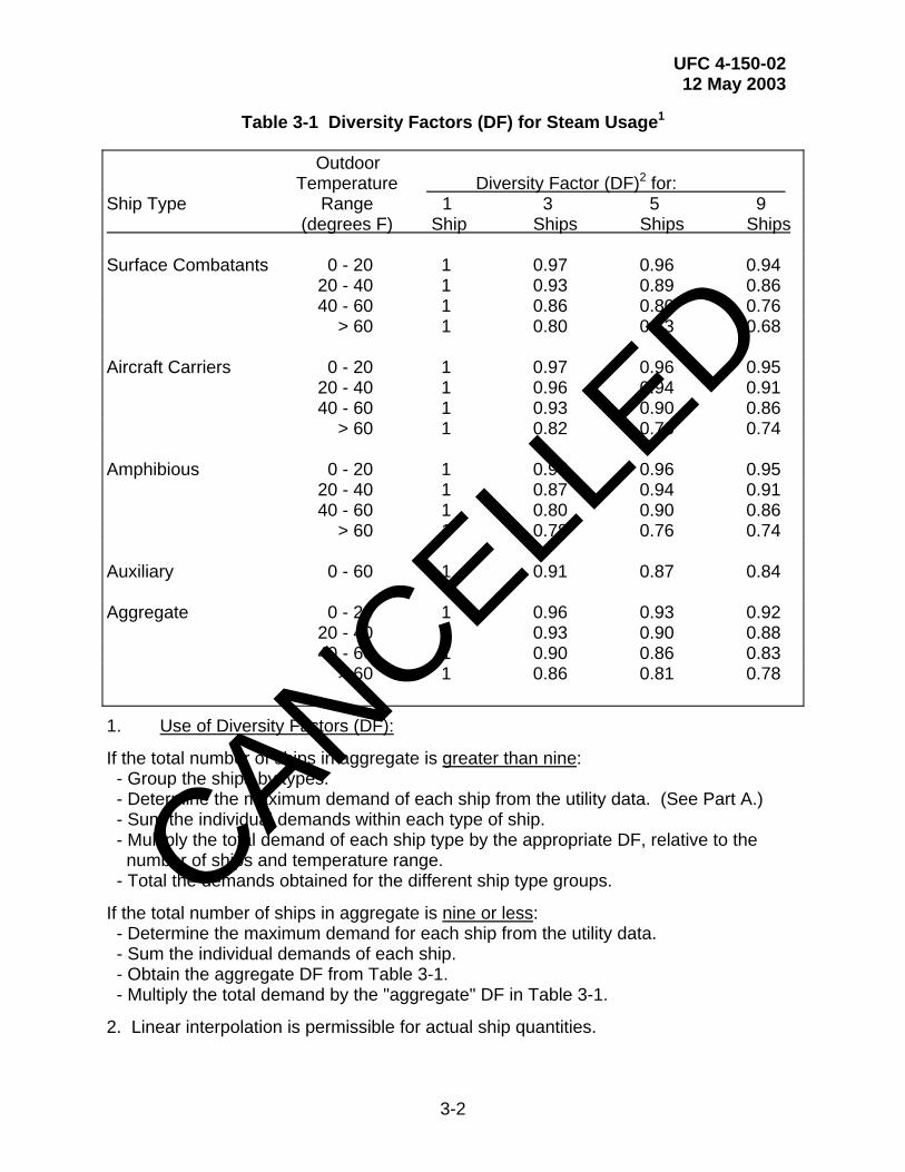
Table 3-1 Diversity Factors (DF) for Steam Usage1
Outdoor Temperature Diversity Factor (DF)2 for: Ship Type Range 1 3 5 9 (degrees F) Ship Ships Ships Ships Surface Combatants 0 - 20 1 0.97 0.96 0.94 20 - 40 1 0.93 0.89 0.86 40 - 60 1 0.86 0.80 0.76 > 60 1 0.80 0.73 0.68 Aircraft Carriers 0 - 20 1 0.97 0.96 0.95 20 - 40 1 0.96 0.94 0.91 40 - 60 1 0.93 0.90 0.86 > 60 1 0.82 0.76 0.74 Amphibious 0 - 20 1 0.95 0.96 0.95 20 - 40 1 0.87 0.94 0.91 40 - 60 1 0.80 0.90 0.86 > 60 1 0.78 0.76 0.74 Auxiliary 0 - 60 1 0.91 0.87 0.84 Aggregate 0 - 20 1 0.96 0.93 0.92 20 - 40 1 0.93 0.90 0.88 40 - 60 1 0.90 0.86 0.83 > 60 1 0.86 0.81 0.78
1. Use of Diversity Factors (DF):
If the total number of ships in aggregate is greater than nine: - Group the ships by types. - Determine the maximum demand of each ship from the utility data. (See Part A.) - Sum the individual demands within each type of ship. - Multiply the total demand of each ship type by the appropriate DF, relative to the number of ships and temperature range. - Total the demands obtained for the different ship type groups.
If the total number of ships in aggregate is nine or less: - Determine the maximum demand for each ship from the utility data. - Sum the individual demands of each ship. - Obtain the aggregate DF from Table 3-1. - Multiply the total demand by the "aggregate" DF in Table 3-1.
2. Linear interpolation is permissible for actual ship quantities.
CANCELLED
UFC 4-150-02 12 May 2003
3-3
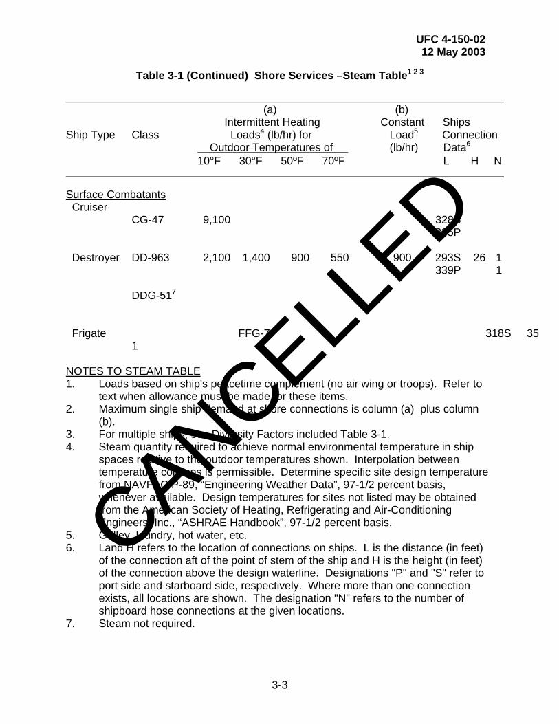
Table 3-1 (Continued) Shore Services –Steam Table1 2 3
(a) (b)
Intermittent Heating Constant Ships Ship Type Class Loads4 (lb/hr) for Load5 Connection
Outdoor Temperatures of (lb/hr) Data6 10°F 30°F 50ºF 70ºF L H N
Surface Combatants Cruiser
CG-47 9,100 328S 335P
Destroyer DD-963 2,100 1,400 900 550 900 293S 26 1
339P 1 DDG-517 Frigate FFG-7 318S 35 1 NOTES TO STEAM TABLE 1. Loads based on ship's peacetime complement (no air wing or troops). Refer to
text when allowance must be made for these items. 2. Maximum single ship demand at shore connections is column (a) plus column
(b). 3. For multiple ships, see Diversity Factors included Table 3-1. 4. Steam quantity required to achieve normal environmental temperature in ship
spaces relative to the outdoor temperatures shown. Interpolation between temperature columns is permissible. Determine specific site design temperature from NAVFAC P-89, “Engineering Weather Data”, 97-1/2 percent basis, whenever available. Design temperatures for sites not listed may be obtained from the American Society of Heating, Refrigerating and Air-Conditioning Engineers, Inc., “ASHRAE Handbook”, 97-1/2 percent basis.
5. Galley, laundry, hot water, etc. 6. Land H refers to the location of connections on ships. L is the distance (in feet)
of the connection aft of the point of stem of the ship and H is the height (in feet) of the connection above the design waterline. Designations "P" and "S" refer to port side and starboard side, respectively. Where more than one connection exists, all locations are shown. The designation "N" refers to the number of shipboard hose connections at the given locations.
7. Steam not required.
CANCELLED
UFC 4-150-02 12 May 2003
3-4
3-1.3.2 Protection. For steam and condensate piping under a pier or wharf, or in a drydock where submergence may occur, piping should be encased in a pressure-testable, prefabricated conduit system. Corrosion-resistant conduit coatings should be selected, and polyethylene heat-shrinkable sleeves and/or high temperature tape wrapping must be used at joints and fittings. Provide pipe hangers and associated support assemblies in accordance with paragraph 2-4.1.3. Hangers should be designed based upon the maximum potential weight of the steam system; that is, the piping is full of water. Identify piping and outlets and color-code in accordance with Chapter 6.
3-1.4 Location and Arrangement of Piping Mains and Branches. As a general rule for all active berthing piers, provide a single main with cross-branch piping to outlets. For repair piers, provide a main on each side of the pier and a cross connection at the outboard end of the pier. Coordinate piping with structural conditions and arrange mains for the best combination of versatility, security, and overall cost. It is normally more desirable operationally to provide a looped main rather than an equivalent single main. Provide isolation valves at appropriate locations for reliability of service during emergency repairs. For graving drydocks, refer to UFC 4-213-10. The location of ships steam connections may be found in SCDB. For discussion of methods to be used to establish shore utility-station spacing on piers and wharves, refer to Chapter 2.
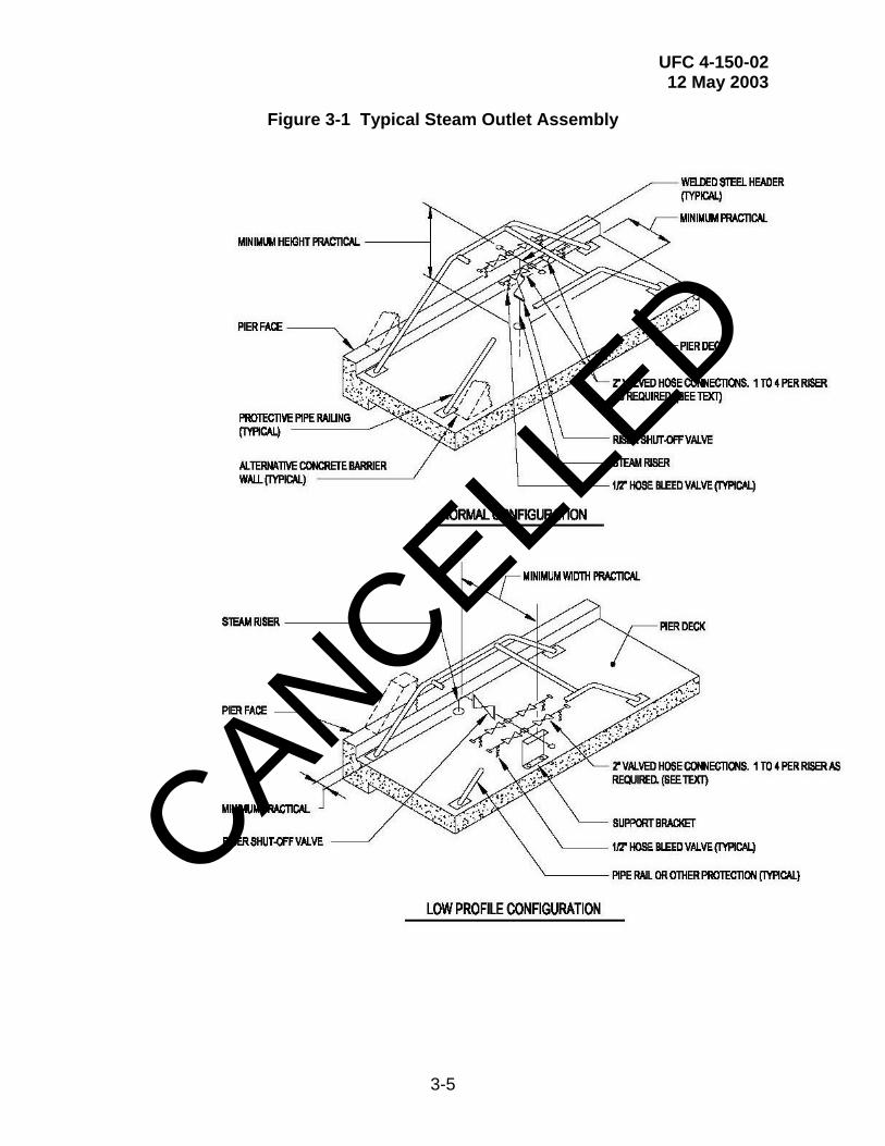
3-1.5 Outlet Design. See Figure 3-1. Naval facilities use 50.8 mm (2 in) hoses (from 1 to 10 per ship) almost exclusively for ship-to-shore steam connections. At locations where 38.1 mm (1-1/2 in) and 25.4 mm (1 in) hoses are used, design for 50.8 mm (2 in) hoses and utilize reducing fittings at hose connections. Total numbers of shipboard steam connections are found in SCDB. The number of hoses actually connected to shore per ship varies with the severity of the climate. For facilities in the coldest climates (see Appendix C, Figure C-1, Regions I and II), assume that all ships connections will be connected to shore. For warmer climates, obtain the demand for the appropriate design temperature; divide by 2500 for 50.8 mm (2 in) hose and by 1250 for 38.1 mm (1-1/2 in) hose. For existing facilities, the maximum number of hose connections actually made for the ships to be berthed may be obtained from the cognizant NAVFAC EFD/EFA OR USACE DISTRICT. Refer to Chapter 2 for a general description of the arrangement and spacing of utility outlets.
3-1.5.1 Steam Outlet Assemblies. The design of steam outlet assemblies is to include the following conditions.
• Provide a shut-off valve for each riser assembly. The valve must be easily accessible.
• Provide a welded steel header after the riser shut-off valve. The header must serve the hose connections.
• The designer is responsible for determining the number of hose connections required at each outlet assembly.
CANCELLED
UFC 4-150-02 12 May 2003
3-5
Figure 3-1 Typical Steam Outlet Assembly
CANCELLED
UFC 4-150-02 12 May 2003
3-6
• Hose connections must be 50.8 mm (2 in) unless instructed otherwise.
• Each hose connection must include a shut-off valve, a 12.7 mm (1/2 in) hose bleeder valve, and a hose connector. Threaded connections are to be avoided in order to prevent loosening of joints due to hose tension.
• Minimum pipe size of each rise assembly must be as follows:
NUMBER OF HOSES RISER SIZE CONNECTED TO RISER MM (INCHES) 1 63.5 mm (2-1/2") 2 76.2 (3") 3 or 4 101.6 mm (4")
3-1.6 Specific Ship Requirements
3-1.6.1 CV and CVN Ship Requirements (All Classes). These ships are normally berthed starboard side-to. Steam is provided to CVNs certified pure at 1034 kPa (150 psi). Galley and hot water requirements should be increased by 50 percent where it is reasonable to assume that the ship's air wing may be on board.
3-1.6.2 Nuclear-Powered Submarine Requirements. Steam supply for nuclear-powered submarines is not required at operational berths. For ship construction or major repair activities, high-pressure steam at 13.8 to 27.6 MPa (2000 to 4000 psi) may be required for test purposes. This supply may be from a permanent plant or from a portable steam generator. The proper selection is dependent upon local weather conditions. Evaluate each location on an individual basis. The cognizant NAVFAC EFD/EFA OR USACE DISTRICT will approve.
3-1.6.3 Troop Carrier Special Requirements (LHA, LHD, LPD, LSD, and LST). Provide steam service at 1034 kPa (150 psi) certified pure. For LHA, LHD, LPD, and LSD increase galley and hot water requirements by 100 percent if it is probable that troops will be aboard while at active berths.
3-1.6.4 Nested Ships. Maximum nested ships demand at shore connections is 8142 kg/h (17,950 pph) based on the requirements of nested CG-47s.
3-1.7 Shore-to-Ship Steam and Feedwater Requirements
3-1.7.1 Quality. Naval Sea Systems Command (NAVSEA) shore-to-ship steam and feedwater quality standards are provided in NAVSEA S9086-AB-ROM-010, Naval Ship's Technical Manual (NSTM), Chapter 220, “Boiler Water/Feedwater - Test and Treatment”, paragraphs entitled: “Shore Steam and Condensed Shore Steam Used as Feedwater”; “Navy and Commercial Facility Shore Steam Certification Requirements”; “Shore Processed Feedwater (Demineralizers, Reverse Osmosis)”; “Shore Source Feedwater Requirements”; and “Makeup Feedwater Demineralizer System”. These standards are given in Table 3-2 and Table 3-3.
CANCELLED

UFC 4-150-02 12 May 2003
3-7
Table 3-2 Shore Steam and Condensed Shore Steam Quality Requirements1 2
CONSTITUENT OR PROPERTY REQUIREMENT
pH 8.0 to 9.5 Conductivity 25 [mu]S/cm maximum2
Dissolved Silica 0.2 ppm maximum
Hardness 0.10 ppm max or 5 ppm as CaCO3 total hardness
Total Suspended Solids 0.10 ppm maximum
1. Steam must be generated from feedwater which is either treated with a chemical oxygen scavenger or mechanically deaerated to a maximum dissolved oxygen content of 15 parts per billion. Shore steam and condensed shore steam used as feedwater must meet the above standards. The use of filming amines is prohibited.
2. [mu]S/cm = micro-Siemens/centimeter = micro-mho/centimeter. The lowest reading on the shipboard conductivity meter is 40.
Table 3-3 Bulk Shore Feedwater Quality Requirements1
CONSTITUENT OR PROPERTY REQUIREMENT
pH 5.4 to 8.2 (process effluent)
Conductivity 2.5 [mu]S/cm maximum (at point of delivery2
Silica 0.2 ppm maximum
1. Produced by method other than condensed steam.
2. [mu]S/cm = micro-Siemens/centimeter = micro-mho/centimeter. CANCELLED

UFC 4-150-02 12 May 2003
3-8
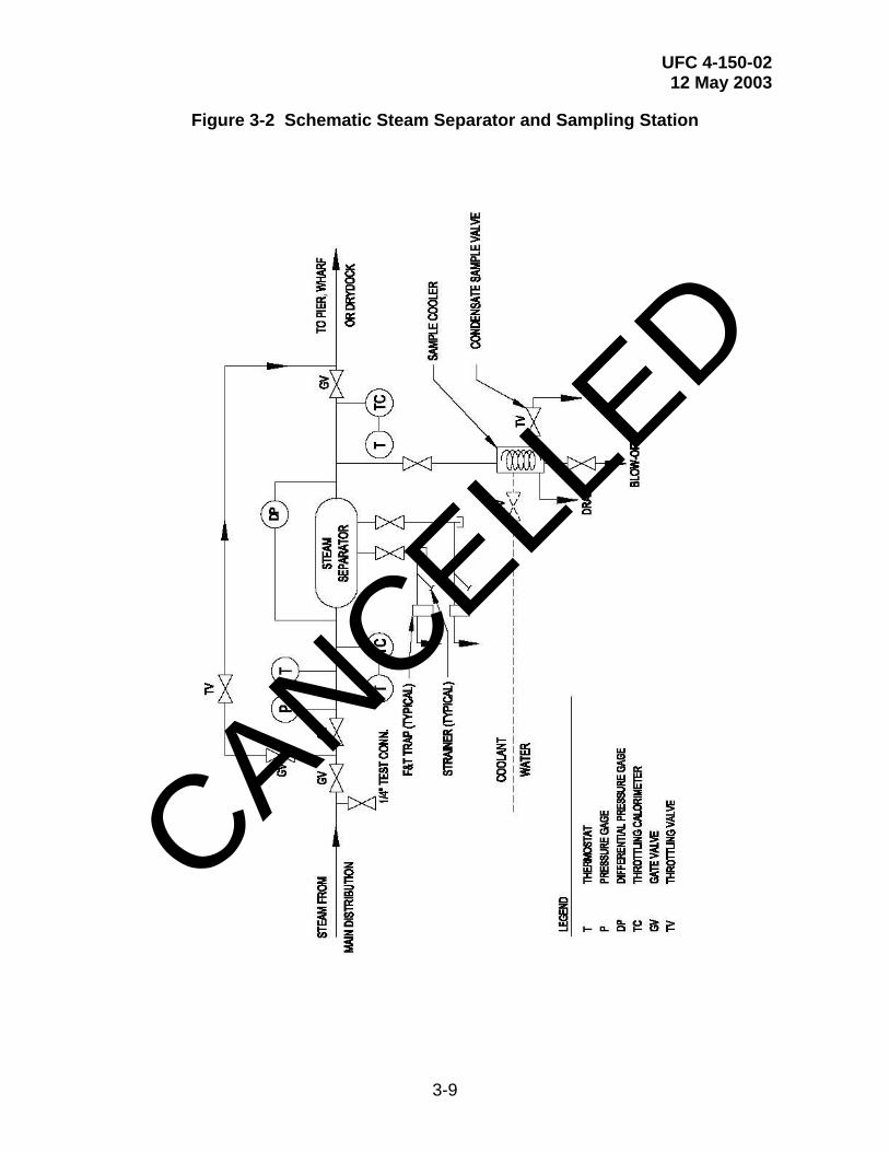
3-1.7.2 Use of Steam Separators. Provide steam separators as required to meet the NAVSEA criteria for the purity of shore-to-ship steam in Navy ports. Properly selected steam separators may be installed in steam mains at piers, wharves, and drydocks. (See S9086-AB-ROM-010 NSTM Chapter 220.) These will provide additional protection against condensate carryover and the resultant steam contamination where such problems are known to exist. Normally, steam separators are not required on piers, wharves, or drydocks if adequate condensate removal is provided at the boiler plant and in shore mains. Steam separators should be used only when necessary and as based upon a case-by-case evaluation of local conditions. If a steam separator should be necessary, then Figure 3-2 provides a typical installation detail that should be used in conjunction with the guidelines of NFESC Test Report No. TN-1586, Steam Separator Test and Evaluation.
3-1.7.3 Sampling. Due to the harsh marine environment, conductivity and pH meters should not be installed permanently on piers or wharves. Condensate sampling stations should be provided at piers and at steam plants. Figure 3-2 also shows a typical installation of a sampling station.
3-1.8 Metering. Where monitoring of usage is required, provide metering of steam flows to piers, groups of piers, or drydocks. Install meters in accessible vaults or in above grade enclosures ashore or on piers. At individual piers or drydocks, use pressure and/or temperature compensated electronic microprocessor type flow meters for good mass flow accuracy and range. Consult with the cognizant NAVFAC EFD/EFA OR USACE DISTRICT to determine if a steam meter installation and maintenance program exists at the Activity. Consult the Activity steam meter program coordinator to integrate the flow meter type selection into any existing meter program. Where metering is not initially required, make provision for ease of future installation by means of concrete vaults or pier access covers.
3-2 COMPRESSED AIR SYSTEMS. In general, a compressed air system is required at all active and repair berths. However, final needs and requirements vary on a pier-by-pier basis. Consult with the Activity for actual requirements, existing construction standards, and preferences. Requirements for graving drydocks are given in UFC 4-213-10.
3-2.1 Demands. Compressed air requirements for selected ship classes are defined in the SCDB. For ships not included in the SCDB use data from a similar ship, or obtain the expected demand from NAVFAC EICO or USACE. CANCELL
ED
UFC 4-150-02 12 May 2003
3-9
Figure 3-2 Schematic Steam Separator and Sampling Station
CANCELLED

UFC 4-150-02 12 May 2003
3-10
3-2.2 Piping System Design Criteria. Design compressed air piping to conform to commercially available standard practices. Also, the designer may consult MIL-HDBK-1003/8, Exterior Distribution of Steam, High Temperature Water, Chilled Water, Natural Gas, and Compressed Air. In addition, provide corrosion protection of steel pipes. Consider an extruded polyethylene or polypropylene exterior coating. Extruded plastic coatings must contain an ultraviolet inhibitor. For coated pipe, use polyethylene, heat-shrinkable sleeves and/or tape wrapping at joints and fittings. Provide pipe hangers and associated support assemblies in accordance with paragraph 2-4.1.3. Identify piping and outlets and color-code in accordance with Chapter 6.
3-2.3 Quality. Compressed air should normally be "commercial" quality. Where breathing quality air and/or an oil-free system is necessary use an oil-free source and/or purification systems. Compressed breathing air compressors must meet the requirements of 29 CFR 1910.134 and the requirements for Grade D breathing air described in ANSI/Compressed Gas Association Commodity Specification for Air, G-7.1-1989. Locate compressors used to supply breathing air so as to prevent entry of contaminated air into the air supply system and breathing air couplings are incompatible with outlets for nonrespirable worksite air or other gas systems.
3-2.4 Size of Piping. For single berths, size the mains in accordance with air quantity per ship data given in the SCDB. Multiple pier demand data for use in design of new compressed air plants and at new facilities should be obtained by evaluating demands at operating Naval berthing and repair facilities which are similar to the proposed facility. The designer should consult with the cognizant NAVFAC EFD/EFA OR USACE DISTRICT. For multiple berthing at a single pier or wharf, including nested ships, use the following diversity factors:
NUMBER OF SHIPS DIVERSITY FACTOR 1 1.0 2 0.8 3 0.7 4 0.6
5 or more 0.5
3-2.4.1 Branches. Branch-pipe sizes should be in accordance with the ships’ usage data defined in SCDB. Where a variable mixture of ships is probable at a given pier, all branch lines should be 76.2 mm (3 in) minimum. However, where carriers may be berthed, branch lines should be 101.6 mm (4 in) minimum.
3-2.4.2 Sizing Method. Determination of pipe size should be in accordance with available friction loss tables. Size mains for a pressure drop of not greater than 34.47 kPa (5 psi) total friction loss from pier or wharf entrance to farthest outlet, and as based upon the designed flow rates. For looped mains, assume flow in both legs of the loop. In all cases, mains should be sized to supply the most outboard ship with 100 percent of the quantity defined in SCDB, and then adjusted for its full-diversified demand.
CANCELLED

UFC 4-150-02 12 May 2003
3-11
3-2.5 Location and Arrangement of Piping Mains and Branches. As a general rule, provide a single compressed air main with cross branch piping to outlets for all active berthing piers and for all repair piers 15.24 m (50 ft) or less in width. For repair piers wider than15.24 m (50 ft), provide a piping main on both sides of the pier and provide a cross connection at the outboard end of the pier (loop configuration). Coordinate piping with structural conditions and arrange mains for the best combination of versatility, security, and overall cost. It is normally more desirable operationally to provide a looped compressed air main rather than an equivalent single main. Provide isolation valves at appropriate locations for reliability of service during emergency repairs. The number of shore compressed air outlets and risers for various ship types is defined in SCDB. Specific ships connection locations (one or two per ship) are also defined. However, compressed air may be required at many locations both on and alongside a ship during maintenance or repair operations. The number of outlets and risers per berth should therefore be integrated within utility groups designed and spaced as discussed in Chapter 2.
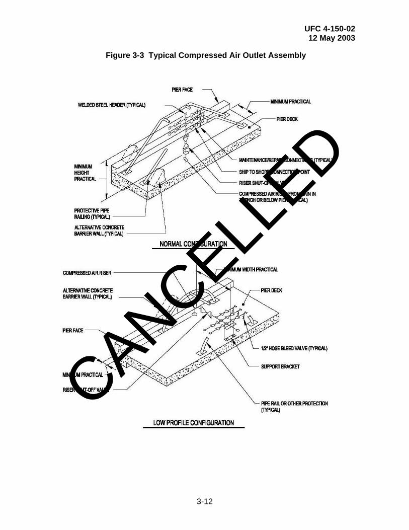
3-2.6 Outlet Design. See Figure 3-3. The size of outlet risers should be the same as that of branch piping. Provide a full-sized accessible shut-off valve in each branch near the outlet riser. Hose couplers for maintenance and repair connections should be quick coupler type and must match those used by the Activity. When the site is an existing facility, the number and size of maintenance and repair hose connections required to match a facility standard may be used in lieu of those given in the following table. Shore couplings for 63.5 mm (2-1/2 in) ship-to-shore connections should be male cam-locking connector with cap which complies with Commercial Item Description (CID) A-A-59326, “Coupling Halves, Quick-Disconnect, Cam-Locking Type” (with supplements). Shore couplings for 101.6 mm (4 in) ship-to-shore connections should be 150-pound flanges with blind flange covers. Refer to Chapter 2 for general description of the arrangement and spacing of utility outlets. Provide a header at the outlet riser, with hose connections (valved outlets and hose couplers) sized as follows:
SIZE OF MAINTENANCE AND REPAIR SHIP-TO-SHORE RISER CONNECTIONS _____ CONNECTION_ 2 inch Four 3/4 inch None 3 inch Two 3/4 inch & Two 1-3/4 inch 4 inch 4 inch Two 3/4 inch & Two 1-1/4 inch 4 inch CANCELL
ED
UFC 4-150-02 12 May 2003
3-12
Figure 3-3 Typical Compressed Air Outlet Assembly
CANCELLED
UFC 4-150-02 12 May 2003
3-13
3-2.7 Requirements for High-Pressure Compressed Air. Many submarines require a high-pressure compressed-air supply in addition to the customary compressed-air requirements. CVN-68 class also requires high pressure air (ref NSTM Chapter 9490). This service may be provided by tapping an available 20.7 MPa (3000 psi) or 31.0 MPa (4500 psi) source, or by utilizing portable compressors. Required ships service size is normally 12.7 mm (1/2 in) or 19.05 mm (3/4 in). The ship's compressors will be used for topoff under emergency conditions. Air quality should be in accordance with NAVSEA S9086-AB-ROM-010, Naval Ship’s Technical Manual (NSTM), Chapter 551, “Compressed Air Plants and Systems”. This chapter requires air to be oil free and dehumidified by a desiccant type dehydrator to a dew point (at atmospheric pressure) of -51 degrees C (-60 degrees F). High-pressure compressed air service is normally portable and provided by the Activity, but the need must be determined on an individual site basis.
3-3 SALTWATER OR NONPOTABLE WATER SYSTEMS. Shore-supplied saltwater or nonpotable water must not be provided to active berthing piers and wharves unless instructed otherwise. However, there are existing piers and wharves that use saltwater or nonpotable water to meet ship fire protection, cooling, and flushing requirements. For drydocks, refer to UFC 4-213-10. For pier and wharf fire protection requirements, refer to UFC 3-600-01 Design: Fire Protection Engineering for Facilities, as well as the criteria in this UFC. Consult with the cognizant fire protection engineer, both at the local level and at the NAVFAC EFD/EFA OR USACE DISTRICT level.
3-3.1 Justification. The use of permanent salt or nonpotable water systems must be justified and approved in advance by NAVFAC EICO. Use the following criteria to establish approval requirements for these systems.
3-3.1.1 Repair Piers and Drydocks. At facilities used for major ship repair in which the repaired ships do not have use of their own pumping capabilities, permanent shore salt or nonpotable water systems are normally utilized. These types of installations do not require prior approval. Design such systems in accordance with applicable requirements defined herein and beginning with paragraph 3-3.2.
3-3.1.2 Active Berthing. Permanent salt or nonpotable water systems should not be provided at active berthing facilities unless instructed otherwise. It is the Navy's intent that ships at active berth will normally rely upon their own pumping capabilities to supply saltwater for flushing/cooling and firefighting. In the event of a major fire or other emergency, shore-based portable pumps and other available station fire apparatus would be utilized to augment the ship's saltwater pumping capability.
Generally, fixed fire protection systems are not required for active berthing piers when the level of the pier is low enough to the waterline such that the responding fire crews can perform drafting operations from the pier. However, with the development of the double-decker type piers, normal fire department operations are restricted due to the elevation of the pier above the water level. Provide dry standpipe systems for piers where construction features restrict fire department vehicle access and/or prevent the fire department from performing drafting evolutions from the pier.
CANCELLED
UFC 4-150-02 12 May 2003
3-14
The system consists of multiple inlet, or pumper, connections and multiple outlet (standpipe) connections located on both levels of the pier.
Locate inlet connections on both sides of the access ramp and size to support flows of 190 l/sec (3,000 gpm.) Pumper connection type should be as preferred by the base fire department, but typically will consist of both 127 mm (5”) Stortz and 63.5 mm (2-½”) connections. This configuration will permit the fire department to obtain water from adjacent fire hydrants, drafting operations from the relieving platform, or a combination of both.
Outlet connections consist of the following:
• Upper level connections consist of a single 127 mm (5”) Stortz outlet and valve or (4) 63.5 mm (2-½”) hose valves. Locate connections at each stair access point to the lower level and at the top of the pier access ramp.
• Lower level standpipe or hose stations consist of (2) 63.5 mm (2-½”) hose valves. Locate hose stations along both sides of the pier, spaced so that all portions of the lower level are within 45 m (150-ft) of a hose connection. Measure distances along a path of travel originating at the hose connection.
Identify locations of the lower level connections on the upper level by color coordinated reflective markers located on the curb along the pier edge. Provide reflective markers to identify all fire protection and ship service connections. Identify locations of lower level connections on the lower level by painting the adjacent pier structural column (bent) red in color.
Main distribution piping on the pier must be a minimum 203 mm (8-inch) diameter, Schedule 40-Galvanized. Loop piping to supply hose stations along both sides. Piping must not infringe on vehicle lanes with respect to clear height requirements.
3-3.1.3 Justification Requirements. At locations where special conditions or hazards exist, permanent salt or nonpotable water systems will be allowed for active berthing and inactive berthing facilities on a case-by-case basis provided: (1) it is adequately justified by the Activity; and (2) it is approved in advance by the NAVFAC or USACE Chief Fire Protection Engineer. Each pier or wharf at a given facility must be considered separately unless the usage of two or more piers is identical. The Station/Activity should submit the following when requesting approval for these systems.
• Identify the type of facility and activities, and describe the special condition(s) or hazard(s) peculiar to this facility upon which this request is based.
• Establish the required pier or facility demand and pressure parameters based on the methods given in paragraph 3-3.2.
CANCELLED
UFC 4-150-02 12 May 2003
3-15
• Provide description and analysis of the options available to provide the required protection such as: (1) permanent system to supply the entire demand; (2) portable pumping systems(s) dedicated or otherwise; and (3) combinations of items (1) and (2). All existing Navy assets must be included in the analysis including any existing permanent systems.
• Provide a life cycle cost analysis for all viable options on a site-specific basis. Perform the analysis in accordance with NAVFAC P-442, Economic Analysis Handbook. The analysis must take into consideration the costs of owning and operating all pertinent plants, both on ships and ashore.
• Make recommendations for the best system to meet the required demand as based on consideration of the special conditions(s) or hazards(s) and on the life cycle cost analysis.
• The demands and pressure parameters of an approved permanent salt or nonpotable water system should be designed as described in paragraph 3-3.2 and all subparagraphs.
3-3.2 Demands and Pressure Requirements. Berthing facilities should conform to the requirements specified below. Note that the requirements differ for overhaul and drydock berthing versus those for active berthing.
3-3.2.1 Drydock, Repair and Inactive Berthing. Nonpotable or saltwater supply should be furnished at drydocks, piers, and wharves as described below. Requirements for selected ship classes are defined in SCDB. For ships not included in SCDB, use data from a similar ship, or obtain the expected demand from NAVFAC EICO. The following criteria should also apply.
• Drydock. Provide sufficient saltwater to meet the requirement of the ship with the highest saltwater demand anticipated to be docked at the drydock. Use the "Total Demand" quantity listed in SCDB. Refer to UFC 4-213-10 for additional requirements at drydocks.
• Repair Berthing. Provide sufficient saltwater to meet the "Total Demand" requirement defined in SCDB for the largest ship to be berthed at the pier plus the aggregate cooling/flushing demand of all remaining ships at the pier, and then multiplied by the diversity factors given below. In general, allow 63 l/s (1000 gpm) minimum for piers serving frigate ships and larger and 32 l/s (500 gpm) minimum for piers serving ships smaller than frigates. Also, do not include nested ships.
NUMBER OF SHIPS DIVERSITY FACTOR 1 1.0 2 0.9 3 0.8 4 0.7
CANCELLED

UFC 4-150-02 12 May 2003
3-16
Over 4 0.6
• Total System Demand. Where a system serves more than one pier, assume only one ship fire will occur for the group of repair piers. The multiple pier supply system should be designed to meet the requirement of the pier with the highest demand plus the aggregate cooling/flushing demand from ships at all remaining piers, and then adjusted by the same diversity factors defined above. To obtain an overall demand that includes drydocks, add the sum of all drydock demands to the multiple pier demand as described herein.
• Pressure Requirement. The saltwater pressure should be 1034 kPa (150 psi) residual pressure (for all ships except submarines) at the most remote outlet. Submarines require only 276 kPa (40 psi). These pressure requirements should be available within 3 minutes of system activation.
3-3.2.2 Active Berthing (Single or Multiple Berths). As stated previously in paragraph 3-3, shore supplied saltwater or non-potable water should not be provided to active berthing piers or wharves. However, there are instance where this occurs. In the criteria given below for saltwater or nonpotable water demands, one of the following conditions of flow governs. (Note: Either the fire protection demand or the cooling/flushing demand may govern. Use whichever is greater.)
• Base fire demand on a fire occurring aboard the ship with the largest fire protection demand plus the cooling/flushing ratings of all other ships connected to the fire protection water systems, and then adjusted for diversity.
• Base cooling/flushing demand on the aggregate of connected ships and then adjusted for diversity.
Requirements for selected ship classes are defined in SCDB. For ships not included in SCDB, use data from a similar ship, or obtain the expected demand from NAVFAC EICO. For CVN-68 class ship include saltwater for firefighting and cooling/flushing when potential exists for ship to be in cold iron status. Total demand equals firefighting plus cooling/flushing flow.
3-3.3 Pumping Equipment. Pumps may be permanent, portable or mobile as justified and approved under the requirements defined in paragraph 3-3.1. In general, pump capacities and heads should be selected to provide for both fire protection and cooling/flushing requirements. Use separate pumps for the two requirements only when specifically allowed or when upgrading an existing system as defined in paragraph 3-3.5.2. Refer to UFC 3-600-01 for requirements of fire pumps and associated equipment. Centrifugal fire pumps should comply with NFPA 20, Centrifugal Fire Pumps. Refer also to MIL-HDBK-1005/7A, Water Supply Systems, for pumping equipment criteria.
CANCELLED

UFC 4-150-02 12 May 2003
3-17
3-3.3.1 Drives. As defined by NFPA 20, fire pumps may be driven entirely by electric motors if either a single reliable power source is available, or if two independent power sources are available. Single reliable power sources need not include dual substations or starting equipment. If the above conditions for use of "electric drive only" cannot be met, design the system such that a minimum of 50 percent of pumping capacity is driven by approved alternative drives such as diesel engines. Portable or mobile pumping equipment is normally driven by remote-starting electric motors (when appropriate) or by diesel or gas-turbine engines.
3-3.3.2 Pressure Control. Pressure must be controlled under varying demands by staging of pumps and by incorporation of surge tanks and/or other suitable equipment. It is imperative to prevent excessive surges due to starting and stopping of pumps. Use a small pressure-maintenance pump to handle low flows. Fire pumps must be equipped for automatic startup upon pressure drop, manual stop, and provision for "manual override startup".
3-3.3.3 Alternative Pump Drive. When a separate cooling/flushing water system is used, a variable speed electric drive may be used to control pressure. Variable speed equipment may also be used for combined fire protection and cooling/flushing systems when approved by the cognizant NAVFAC EFD/EFA OR USACE DISTRICT. Variable speed drive equipment should be selected from types that have been proven by successful use. Adjustable frequency type variable speed systems are preferred because of their higher efficiency. See MIL-HDBK 1004/4, Electrical Utilization Systems, for additional requirements regarding variable speed systems.
3-3.3.4 Location. Permanent pumping equipment for individual piers, wharves, or drydocks should be located ashore and as near as possible to the pier, wharf or drydock. It is highly preferred to provide vertical pumps with wet sump/intake configuration. Where this is impractical, then the pumps may be placed in an enclosure on or alongside a pier or wharf. The pump columns must be adequately protected from wave action and floating debris. Portable or mobile pumping equipment may also be placed on pier decks or on floating platforms moored to the pier.
3-3.3.5 Materials. Care must be taken when specifying pump materials for nonpotable water service. Where salt or brackish waters are present, the potential for galvanic and crevice corrosion is severe. Steel and cast iron, ordinary brass and bronze, and most stainless steels are not suitable for these corrosive water sources. Specially coated steel and cast iron as well as 400 series stainless steel have proven to be ineffective. Material selection should be based on a thorough investigation of the site and operational conditions. The construction specifications should be explicit as to materials required for each major part, indicating appropriate ASTM designation and Unified Numbering System (UNS) number per Metals and Alloys in the Unified Numbering System. Since it is impractical to list all parts, a sentence such as the following should be included:
"Minor parts not listed should be of comparable materials with equivalent corrosion resistance to the materials listed."
CANCELLED
UFC 4-150-02 12 May 2003
3-18
Submittals for Government approval, including material lists, should be required for pumps. Materials generally considered appropriate for salt and brackish waters are as follows:
APPLICATION MATERIAL ASTM UNS All wetted parts 316 SS, or A276* S31600
316L SS A276* S31603 Shafts/Couplings Nickel-Copper B164* N04400
(Monel) and B165* N04400
All wetted parts, Alum Bronze, or B148* C95200 except shafts/cplgs Ni-Alum Bronze B148* C95500
* Full titles for ASTM Standards can be found in Appendix A.
In salt water it is important to avoid dissimilarity of parts. Pumps constructed of type 316L stainless steel or nickel aluminum bronze with monel shafts are preferred. In brackish water, cost savings can be realized by allowing acceptably small dissimilarities. Aluminum bronze pumps with type 316 stainless steel shafts are a reasonable alternative. The presence of sand/grit must also be considered. Pumps constructed of stainless steels handle sand/grit better than pumps constructed of bronze and other copper alloys. However, saline waters corrosion concerns are still paramount.
3-3.4 Piping and Outlets
3-3.4.1 Size of Mains. Piping systems must be designed to provide the required residual pressure at the rated design flows to the berths farthest from the pumping location. Where a common shore pumping and distribution system feeds several piers or drydocks, the shore distribution system must be sized to deliver the design firefighting flow to any one of the piers or drydocks while cooling/flushing flows continue to all other locations.
3-3.4.2 Location and Arrangement of Mains. As a general rule, when permanent mains are placed on piers 15.24 m (50 ft) or less in width, provide a single main with branch lateral pipes for outlets on both sides of the pier. For piers wider than 15.24 m (50 ft), provide a main on both sides of the pier with a cross connection at the outboard end of the pier (loop configuration). Coordinate piping with structural conditions and arrange mains for the best combination of versatility, security, and overall cost. It is normally more desirable operationally to provide a looped main than an equivalent single main. Provide isolation valves at appropriate locations for reliability of service during emergency repairs. Segregation valve should be placed in the fire main loop so that the maximum distance between any two adjoining valves does not exceed 61 m (200 ft).
3-3.4.3 Location and Spacing of Outlets. The pier location of ships' saltwater connections are defined in SCDB. Refer to Chapter 2 for a description of the methods
CANCELLED
UFC 4-150-02 12 May 2003
3-19
to be used in establishing shore utility-station spacing on piers and wharves. Hose valve manifolds should be provided in sufficient numbers such that all parts of the ship can be reached by at least two 30.5 m (100 ft) hoses. For spacing in drydocks, refer to UFC 4-213-10.
3-3.4.4 Outlet Design. See Figure 3-4. The typical outlet should consist of a 152.4 mm (6 in) branch main and riser feeding a manifold arrangement of three 63.5 mm (2-1/2 in) and one 101.6 mm (4 in) valved hose connections. Where portable pumping systems are used, standpipe connections may be provided on some (or each) of the outlet risers for connection to the portable pumping system discharge hose. For certain large ships, the above outlet requirements should be modified as defined in paragraph 3-3.5. Provide four 101.6 mm (4 in) valved hose connections in a manifold arrangement at the outboard end of large piers. These outlets are to serve fireboat or large-volume portable-pump connections. Where berthing is designed exclusively for tugboats, work boats, or other small craft having a "Salt Water From Shore" requirement of not more than 39.4 l/s (625 gpm), properly spaced 101.6 mm (4 in) risers having two to three 63.5 mm (2-1/2 in) connections may be used in lieu of the above. All connections should be protected by a chained cap. At each designated pier in each naval station where oceangoing U.S. merchant and foreign ships are expected, provide two international shore connections. See Figure 3-5.
3-3.4.5 Materials and Installation Criteria. Pipe and fittings should conform to MIL-HDBK-1005/7A, Water Supply Systems, as applicable to piers and wharves. Use pipe, fittings and valves pressure-rated at 1724 kPa (250 psi) minimum. Hose threads should be National Standard hose-coupling threads, 7-1/2 threads/inch, or as approved by the cognizant Fire Protection Engineer. Materials for valves should conform to requirements for pumps as defined in paragraph 3-3.3.5. For piping on a pier or wharf, evaluate the relative advantages of cement-lined ductile iron versus cement-lined steel pipe with an extruded polyethylene or polypropylene exterior coating. An ultra violet inhibitor must be used in polyethylene coatings that will be exposed to sunlight. For coated pipe, use polyethylene heat-shrinkable sleeves and/or tape wrapping at joints and fittings. Provide pipe hangers and associated support assemblies in accordance with paragraph 2-4.1.3. Provide means of pipe movement due to thermal expansion, preferably by the use of expansion loops and offsets. Also, provide for differential movement of piping at pier expansion joints. Piping and outlets must be identified and color-coded in accordance with Chapter 6.
3-3.5 CV, CVN, LHA, and LHD Requirements (All Classes). At existing installations where insufficient saltwater pressure exists, the pressure should be increased to provide 1034 kPa (150 psi) residual pressure at the pier outlets. Pump-discharge pressure must be sufficient to provide the required residual at the rated design flow. The following special requirements apply to these large class ships:
CANCELLED
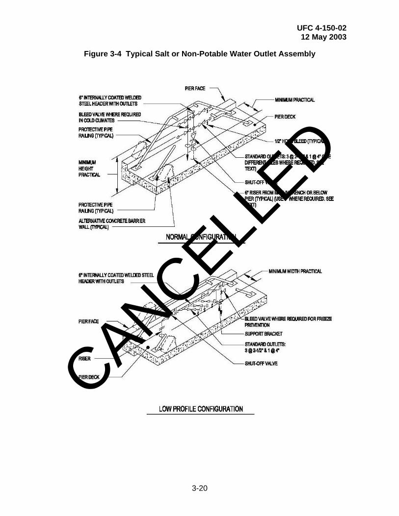
UFC 4-150-02 12 May 2003
3-20
Figure 3-4 Typical Salt or Non-Potable Water Outlet Assembly
CANCELLED
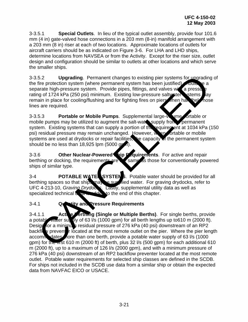
UFC 4-150-02 12 May 2003
3-21
3-3.5.1 Special Outlets. In lieu of the typical outlet assembly, provide four 101.6 mm (4 in) gate-valved hose connections in a 203 mm (8-in) manifold arrangement with a 203 mm (8 in) riser at each of two locations. Approximate locations of outlets for aircraft carriers should be as indicated on Figure 3-6. For LHA and LHD ships, determine locations from NAVSEA or from the Activity. Except for the riser size, outlet design and configuration should be similar to outlets at other locations and which serve the smaller ships.
3-3.5.2 Upgrading. Permanent changes to existing pier systems for upgrading of the fire protection system (where permanent system has been justified) should be a separate high-pressure system. Provide pipes, fittings, and valves with a pressure rating of 1724 kPa (250 psi) minimum. Existing low-pressure saltwater systems may remain in place for cooling/flushing and for fighting fires on piers when handheld hose lines are required.
3-3.5.3 Portable or Mobile Pumps. Supplemental large-volume portable or mobile pumps may be utilized to augment the salt-water supply from a permanent system. Existing systems that can supply a portion of the requirement at 1034 kPa (150 psi) residual pressure may remain unchanged. However, when portable or mobile systems are used at drydocks or repair facilities, the capacity of the permanent system should be no less than 18,925 lpm (5000 gpm).
3-3.6 Other Nuclear-Powered Ship Requirements. For active and repair berthing or docking, the requirements are the same as those for conventionally powered ships of similar type.
3-4 POTABLE WATER SYSTEMS. Potable water should be provided for all berthing spaces so that ships may be supplied water. For graving drydocks, refer to UFC 4-213-10, Graving Drydocks. Lastly, supplemental utility data as well as specialized technical data is added to the end of this chapter.
3-4.1 Quantity and Pressure Requirements
3-4.1.1 Active Berthing (Single or Multiple Berths). For single berths, provide a potable water supply of 63 l/s (1000 gpm) for all berth lengths up to610 m (2000 ft). Design for a minimum residual pressure of 276 kPa (40 psi) downstream of an RP2 backflow preventer located at the most remote outlet on the pier. Where the pier length accommodates more than one berth, provide a potable water supply of 63 l/s (1000 gpm) for the first 610 m (2000 ft) of berth, plus 32 l/s (500 gpm) for each additional 610 m (2000 ft), up to a maximum of 126 l/s (2000 gpm), and with a minimum pressure of 276 kPa (40 psi) downstream of an RP2 backflow preventer located at the most remote outlet. Potable water requirements for selected ship classes are defined in the SCDB. For ships not included in the SCDB use data from a similar ship or obtain the expected data from NAVFAC EICO or USACE.
CANCELLED
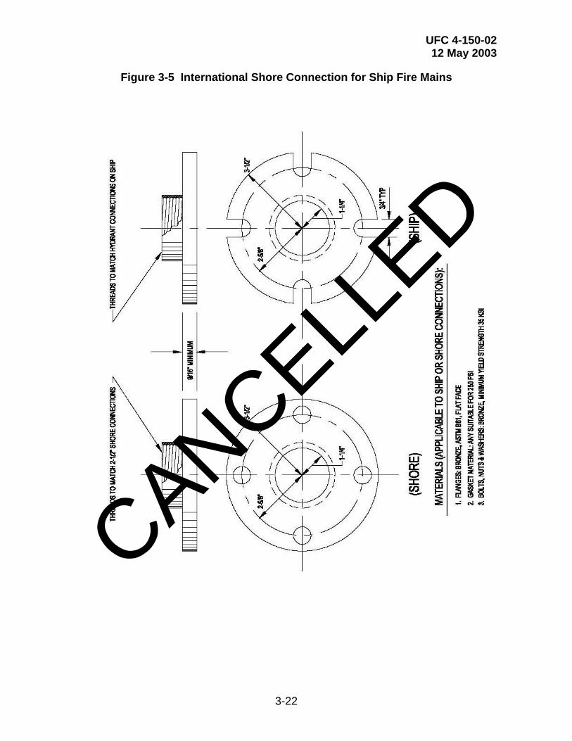
UFC 4-150-02 12 May 2003
3-22
Figure 3-5 International Shore Connection for Ship Fire Mains
CANCELLED

UFC 4-150-02 12 May 2003
3-23
Figure 3-6 Salt or Non-Potable Water for CV, CVN Classes at Pier
CANCELLED
UFC 4-150-02 12 May 2003
3-24
3-4.1.2 Repair Berthing. The potable water requirements are defined in SCDB. Add the quantities indicated for each ship (including nested ships) and that total available on the pier. Base the peak rate of flow for sizing the main on providing the entire daily flow requirements defined in SCDB, applied to all ships on a pier or wharf, at a constant flow rate, within an 8-hour period, and at a residual pressure of 276 kPa (40 psi) minimum at the furthest shore connections. It is noted that this data is based on 114 lpd/man (30 gpd/man).
3-4.1.3 Multiple Piers. Determine total usage for multiple piers by summing daily flows for all ships at all piers or wharves assuming 114 lpd/man (30 gpd/man). Determine the peak-flow rate for multiple piers by summing peak-flow rates for all piers or wharves as determined by the method described above and then multiplied by a diversity factor of 0.75.
3-4.2 Piping System Design Criteria. For piping materials and installation requirements, refer to MIL-HDBK-1005/7A, Water Supply Systems. Ductile iron is typically used for the main lines while PVC or copper is used for branch lines. For piping under a pier or wharf, evaluate the relative advantages of cement-lined ductile iron versus cement- lined steel pipe with an extruded polyethylene or polypropylene exterior coating. Provide an ultra violet inhibitor in polyethylene or polypropylene coatings exposed to sunlight. For coated pipe, use polyethylene, heat-shrinkable sleeves and/or tape wrapping at joints and fittings. Type of joint requires particular consideration. Provide pipe hangers and associated support assemblies in accordance with paragraph 2-4.1.3. Provide means of pipe movement due to thermal expansion, preferably by use of expansion loops or offsets. Also, provide for differential movement of piping at pier expansion joints. Consider effects of transients from waterhammer.
3-4.3 Location and Arrangement of Piping Mains. As a general rule, provide a single water main with cross-branch piping to outlets for active berthing piers and for repair piers 15.2 m (50 ft) or less in width. For repair piers wider than 15.2 m (50 ft), provide piping mains on both sides of the pier with a cross connection at the outboard end of the pier (loop configuration). Coordinate piping with structural conditions and arrange mains for the best combination of versatility, security, and overall cost. Normally, it is more desirable to provide a looped main rather than an equivalent single main. Provide isolation valves at appropriate locations for reliability of service during emergency repairs.
3-4.4 Piping and Outlets. See Figure 3-7. Provide at least one 63.5 mm (2-1/2 in) connection at each service outlet except as specified in paragraph 3-4.6 for large ship requirements or where nesting is anticipated. Branch piping from mains to outlet risers should be not less than 63.5 mm (2-1/2 in), and not less than 101.6 mm (4 in) where dual 63.5 mm (2-1/2 in) connections are fed by a common branch. Terminate shore connections with a 63.5 mm (2-1/2 in) gate valve with hose threads (national hose threads) and a chained cap. Provide a reduced-pressure type backflow prevention device in accordance with MIL-HDBK-1005/7A. Identify and color-code potable water outlets on piers and wharves in accordance with Chapter 6. If static pressure in supply
CANCELLED

UFC 4-150-02 12 May 2003
3-25
mains is greater than 552 kPa (80 psi) for any portion of the day, then provide regulators set at 552 kPa (80 psi) maximum.
Figure 3-7 Typical Potable Water Outlet Assembly
CANCELLED
UFC 4-150-02 12 May 2003
3-26
3-4.5 Location and Spacing of Outlets. The pier locations of ships potable water connections may be determined by the data defined in SCDB. Refer to Chapter 2 for a description of methods to be used in establishing shore-utility station spacing on piers and wharves.
3-4.6 Specific Ship Requirements
3-4.6.1 CV and CVN Ship Requirements (All Classes). Design systems as specified above except provide a 101.6 mm (4-in) branch line, a 101.6 mm (4 in) reduced pressure backflow prevention device, and an outlet assembly at outlet locations 3 and 4 of Figure 3-6. Provide a 101.6 mm to 63.5 mm (4-in to 2-1/2 in) reducer for each location to allow the use of these outlets by ships other than carriers.
3-4.6.2 LHA and LHD. Design systems as specified for CV/CVN class ships except provide dual outlets at each utility connection group, one 101.6 mm (4-in) reduced-pressure backflow prevention device, and an outlet assembly near the center of the berth. Provide a 101.6 mm to 63.5 mm (4-in to 2-1/2 in) reducer to allow use of the 101.6 mm (4 in) outlet with other ships.
3-4.6.3 Additional Requirement for Nuclear-Powered Ships. A "pure" water supply as defined by NAVSEA is required for all nuclear-powered ships. Due to the quantities involved and the problems of contamination and quality control, tank truck delivery will normally be used rather than the installation of piping and outlets on the pier. Location(s) of the tank truck must be coordinated with all other pier features. Coordinate with the cognizant NAVFAC EFD/EFA OR USACE DISTRICT.
3-4.7 Quality. Refer to MIL-HDBK-1005/7A. The quality of water must meet or exceed the requirements of 40 CFR, Part 141, U.S. Environmental Protection Agency's National Primary Drinking Water Regulations and the National Secondary Drinking Water Regulations.
3-4.8 Metering. Provide metering of potable water supply to piers or groups of piers unless instructed otherwise. See paragraph 2-5. Use compound-disc or magnetic-flow meters to achieve a high range of registration.
3-5 POL SYSTEMS. Refer to MIL-HDBK-1022A. Fuel and lube oil connection locations on various ships are defined in SCDB. Pier fueling connections and hoses must be kept a minimum of 7.6m (25 ft) away from any possible ignition sources, such as pier power outlets, telephone terminal panels, and fire alarm equipment. Required POL connection sizes must be obtained from specific ship data available from NAVSEA. General requirements for pipe hangers and support assemblies (paragraph 2-4.1.3) and for metering (paragraph 2-5) are applicable. Identify POL outlets on piers and wharves and color-code in accordance with Chapter 6. POL piping systems also require special consideration for protective coatings and cathodic protection systems. See paragraph 2-4.4. Refer to military specifications MIL-C-52404B, Connection Hose, Fire and Water, and MIL-S-12165F, Strainer Suction, Fire Hose, and Strainer Suction, Hose for POL connection types. Consult with the cognizant
CANCELLED

UFC 4-150-02 12 May 2003
3-27
fire protection engineer, both at the local level and at the NAVFAC EFD/EFA OR USACE DISTRICT level.
3-6 OILY WASTE SYSTEMS. For typical ship-to-shore connection requirements, see Figure 3-8. Oily waste collection must be provided at all berths for 6.3 l/s (100 gpm.) Oily waste system requirements for selected ship classes are defined in the SCDB. For ships not included in the SCDB, use data from a similar ship or obtain the expected demand from NAVFAC EICO or USACE.
The system is usually a fixed piping system. However, tank truck or barges may be used for transient berths if allowed by the Activity. Ship waste oily barges (SWOB) should not be used at submarine berths due to potential hull damage. Design ships oily waste (bilge water) systems in accordance with MIL-HDBK-1005/9, Industrial and Oily Wastewater Control. Also, refer to 40 CFR, Part 1700, Uniform National Discharge Standards for Vessels of the Armed Forces, and to NAVSEA S9593-BF-DDT-010, Oil Pollution Abatement System for ship design. Connection locations for ships oily waste are defined in the SCDB. Refer to Chapter 2 for a description of utility spacing requirements. In climates subject to freezing temperatures, oily waste lines must be properly protected. Refer to Chapter 6.
3-6.1 Pierside and Barge Collection of Shipboard Oily Waste. Shipboard oily waste must not be directly discharged to public waters. In many cases it is unsuitable for discharge to a POTW. Requirements are: (1) provide full treatment to direct discharge standards; or (2) provide pretreatment to reduce pollutants to acceptable levels for municipal sewer discharge. Bilge wastes are normally the primary influent (both in volume and contaminant concentration) to an oily waste treatment system. Occasionally, compensating ballast water is discharged from ships and barges directly overboard. As of this writing, Puget Sound, Washington activities are required by the local regulatory agencies to collect compensating ballast water during ship's refueling operations. This waste contains lower contaminant levels than bilge wastes but usually requires treatment before disposal. Lastly, the designer should refer to the Naval Facilities Engineering Service Center’s (NFESC) Bilge and Oily Wastewater Treatment System as an alternative system for pollution prevention. Every project must be evaluated on a project-by-project basis. The designer must consult with the cognizant NAVFAC EFD/EFA OR USACE DISTRICT, the Activity, and the responsible Environmental Engineers, both at the local level and at the NAVFAC EFD/EFA OR USACE DISTRICT level.
CANCELLED
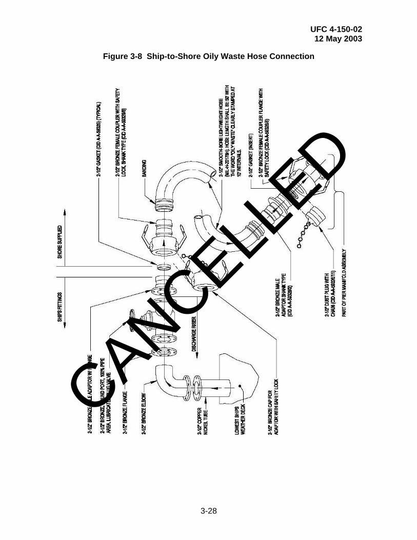
UFC 4-150-02 12 May 2003
3-28
Figure 3-8 Ship-to-Shore Oily Waste Hose Connection
CANCELLED
UFC 4-150-02 12 May 2003
3-29
3-6.2 Ship Oily Waste Generation. Collection may take the form of transfer systems to trucks or barges, or a facility pipeline system. Coordinate with environmental requirements to provide an environmentally acceptable collection system with the most economical life cycle cost.
3-6.2.1 Primary sources of ship-generated oily wastewater are bilges, oily waste holding tanks for collecting lubricating oils and water contaminated fuel, condensate lines, and tank cleaning water. Sonar dome pumping water is not normally collected as part of the oily waste collection system. The oil content in the bilge water normally varies from 0.01 percent (100 ppm) to 1.0 percent (10,000 ppm). The rest is mostly saltwater of unknown chloride content. The oil content of ship discharges overboard is limited to 20 ppm or less within 12 nautical miles of the nearest land. In ports that restrict the direct discharge of ballast water, the ballast water can be discharged from most ships (other than tankers) through a large diameter piping system to a ship waste oily barge (SWOB) or a YON vessel. Compensating ballast water can also be discharged directly to a pier collection system provided the liquid can discharged by gravity flow (from ship to pier connection) and the back pressure can be kept to a minimum. The Navy policy on classification of oily wastewater is that the oily waste and waste oil (OWWO) become a waste only upon removal from the ship. In general, bilge water should be treated like any other waste.
3-6.3 Pumping Equipment. Provide basket or bar type screens on a pump inlet that can be easily removed and cleaned from an easily accessible and safe location.
3-6.3.1 Determine pump capacity and operating cycle. In order to reduce mechanical formation of emulsion at oily waste treatment plants, use positive displacement pumps (in lieu of centrifugal pumps) with pressure relief valves. Pumps should pass solids having a diameter 3 mm (0.125 in).
3-6.3.2 Provide controls suitable for Class I, Division 1, Group D hazardous classification. Use float or sonic type level controllers for pump control and alarm. Air bubbler type controllers must not be used. Provide a discharge pump control valve to minimize surge effects on equalization basins located at oily waste treatment plants. (This requirement is not applicable for positive displacement pumps.) Provide an alarm system for overflow or power failure. Provide manual override of automatic pump controllers. Low-level alarm conditions must lock out all pumps and must require manual resetting.
3-6.4 Piping Systems. Piping requirements are similar to requirements for sewage systems. (See paragraph 3-7 and the associated subparagraphs.) Piping material is typically galvanized steel. However, some local environmental regulations require double-wall piping systems. Consult with the Activity and the cognizant NAVFAC EFD/EFA OR USACE DISTRICT. Provide pipe hangers and associated support assemblies in accordance with paragraph 2-4.1.3. Identify oily waste outlets on piers and wharves and color-code in accordance with Chapter 6.
CANCELLED

UFC 4-150-02 12 May 2003
3-30
3-6.5 Metering. Unless instructed otherwise, specify the following to monitor the system: (1) accumulating flow meter; (2) elapsed time meter for pumps and ventilator; and (3) pump suction and discharge pressure gages. Provide gages with oil-filled diaphragm and cutoff valves. Consult with the cognizant NAVFAC EFD/EFA OR USACE DISTRICT for any additional requirements. See paragraph 2-5 for additional metering requirements.
3-7 SEWAGE SYSTEMS
3-7.1 Introduction. Design information on wastewater collection and transmission systems is extensively covered in Water Environment Federation (WEF) MOP FD-5, Gravity Sanitary Sewer Design and Construction. This section addresses two wastewater collection and transmission topics that are not addressed in WEF MOP FD-5: (1) pier and wharf facilities; and (2) drydock facilities.
3-7.2 Specialized Shipboard Sewage Characteristics and Parameters. Designing sewage collection systems for shipboard wastewater requires special and unique conditions that the designer must take into account. All of these special issues must be addressed and resolved.
3-7.2.1 Characteristics of Ship Holding Tank Discharges. Ship holding tank discharges can be a major source of wastewater. These wastewaters have the following general characteristics.
• A ship's wastewater is primarily domestic wastewater but may also contain industrial wastewater depending on the ship operations.
• A ship's wastewater is more concentrated than typical domestic wastewater, a result of specific design features of the ship's wastewater collection systems.
• A ship's wastewater may contain high concentrations of dissolved solids, chloride, sulfates, and sodium if seawater flushing or ballast systems are used.
3-7.2.2 Ship Discharge Values. SCDB defines the maximum sewage discharge values of a ship's complement, daily flow, maximum discharge, number of pumping stations, total number of pumps, and number and location of discharge connections. Where destroyers or submarines are nested next to a tender berthed at a pier, the nested ships will discharge into the tender. The tender will then discharge to the pier's sewage collection system at the rate listed for the tender. For nested ships, it is suggested to provide a pressure manifold to reduce peak demand flow.
3-7.2.3 Flow Rate Variations. Domestic wastewater flows at piers, wharves and drydocks can be expected to exhibit seasonal and other weather-influenced flow variations. In addition, the effect of industrial and ship discharge flows as well as the variable nature of military operations may significantly affect flow variations. To
CANCELLED

UFC 4-150-02 12 May 2003
3-31
minimize flow variations, flow equalization should be considered. Equalization can be applied to specific flows (such as industrial flows or other specialized flow types) that exhibit wide variations to the entire wastewater flow. When calculating flows, consider the following.
• Industrial flows such as vehicle and aircraft wash facilities. If these flows coincide with peak domestic flows, then they should be added to the peak flows.
• Ship holding tank discharge flows. Flow rates will depend on the total volume of flow and the time required to convey the wastewater to the treatment facility. Design equalization systems to equalize the flows in order to minimize their effects on peak flows. Consider conveying the ship wastewaters to the treatment facility at night when domestic flows are low.
• Intermittent flows due to military functions. Periods of increased sewage flows will occur because of training activities or other personnel mobilization exercises common to military installations. Training activities or other mobilization exercises will create short-term increases in domestic wastewater and possibly industrial flows. These intermittent activities may create the peak wastewater flow rate. Design the sewage collection system to handle routine variations in flow resulting from training and other routine military exercises. The design must ensure acceptable performance with reasonable operational costs. (For example, an equalization system may provide flow and load dampening to accommodate these significant variations.) However, do not design facilities to accommodate peak surges resulting from emergency military mobilizations.
• Intermittent periods of reduced use. Low flows can also be a problem. Therefore, design the wastewater facility to operate efficiently over a range of flows. (For example, provide parallel trains that can be taken out of service.)
• Changes in requirements or military mission. Designs should include provisions for the system's expansion and contraction as well as system modifications due to more stringent effluent requirements or military mission changes. In general, maximize operational flexibility.
3-7.2.4 Wastewater Loadings. Wastewater loadings are typically calculated based on the projected flows and wastewater pollutant concentrations and are expressed in pounds per day (lb/d) or kilograms per day (kg/d). Where possible, determine loadings by analyzing the wastewater to be treated. Consult with the Activity and the cognizant NAVFAC EFD/EFA OR USACE DISTRICT to obtain collected data and specific instructions.
CANCELLED
UFC 4-150-02 12 May 2003
3-32
3-7.2.5 Ship Sewage. Ship sewage settles well and is amenable to biological treatment, but it may be septic. Table 3-4, "Typical Ship Sewage Concentrations", define typical concentration values. Wastes from shipboard industrial activities are not included. High dissolved solids, chloride, sulfates, and sodium concentrations apply when seawater flushing or ballast systems are used. For more information on ship sewage, refer to NAVSEA S9086-AB-ROM-010, Naval Ship’s Technical Manual (NSTM), Chapter 593, Pollution Control.
3-7.2.6 Effect of Wastewaters with High Seawater Content.
• Performance. High concentrations of seawater tend to inhibit biological treatment. Process inhibition is related to the chloride concentration of the wastewater.
(1) For new designs: Currently, there is an absence of pilot plant data or treatment data from similar wastewaters. Consequently, compensate for high seawater content according to the data presented in Table 3-4.
(2) In analyzing the capacity of existing treatment facilities to receive ship's wastewater, use figures defined in Table 3-5. If these indicate overloading solely because of chloride inhibition, conduct pilot plant tests before planning any expansion. Consult with the Activity and the cognizant NAVFAC EFD/EFA OR USACE DISTRICT for instructions.
(3) Sudden changes in chloride concentration may upset biological processes. Consider equalization storage to limit chloride variation at the wastewater facility. For chloride concentrations in excess of 5000 mg/L, provide design limitations of 200 mg/L/h.
• Maintenance. High seawater content in wastewater will aggravate incrustation problems. Avoid fine bubble air diffusion systems and design orifices to facilitate periodic cleaning of mineral deposits. This is especially applicable to orifices in trickling filter flow distributors or in aeration devices. Use care in selecting construction and equipment materials. CANCELL
ED

UFC 4-150-02 12 May 2003
3-33
Table 3-4 Typical Ship Sewage Concentrations
CHARACTERISTIC
CONCENTRATION (mg/L)
Total suspended solids Total dissolved solids Chlorides Sulfates Sodium Other dissolved solids Biochemical oxygen demand (BOD)
600 20,000 11,000 1,500 6,200 1,300 400
Table 3-5 Chloride Inhibition of Biological Nitrification
PROCESS
MAXIMUM CHLORIDE CONCENTRATION
FOR NO INHIBITION
CONCENTRATION FOR CHLORIDES IN EXCESS OF
MAXIMUM LEVEL (1)
Trickling filters and rotating biological contactors
5,000 mg/L Referring to appropriate design loading curve, decrease loading an amount corresponding to one percentage point of removal efficiency per 1,000 mg/L of chlorides in excess of 5,000 mg/L
Activated sludge 5,000 mg/L Decrease loading by 2% per 1,000 mg/L chlorides in excess of 5,000 mg/L
Aerobic and facultative lagoons
8,000 mg/L Increase detention time by 2% per 1,000 mg/L chlorides in excess of 8,000 mg/L
NOTES TO TABLE 3-5
1. Highest average chloride concentration expected over 24 hours.
CANCELLED
UFC 4-150-02 12 May 2003
3-34
3-7.3 Pier and Wharf Systems. Design the ship sewage collection system for the peak flow from the maximum planned berthing with sewer flowing full. Base the design on maximum discharge of ship pumps. Provide a gravity flow system unless approved otherwise.
3-7.3.1 Layout/Location. See Figure 3-9. Provide a single 101.6 mm (4-in) pressure rated manifold assembly at each berth. Each manifold assembly should have four single 101.6 mm (4-in) diameter pressure sewer connectors. This layout has the following advantages:
• It provides large reduction in peak flows by combining multiple discharges from a ship (or nested ships) into a single stream, thereby increasing the head on the ship’s pumps.
• By reducing peak flow, it allows berthing of other ship types included in the berthing plan.
• It is self-regulating and self-cleaning plus avoids failure or maintenance problems inherent in regulating valves or other similar devices.
3-7.3.2 Additional Requirements. See Figure 3-10 for typical collection sewer layouts on different pier types. Properly isolate each berthing space in order to prevent pumping from one berth into another and to allow ships with lower head pumps to discharge into the pier sewer.
Isolate the berths by providing one separate manifold assembly at each berth and then connect the manifold assembly directly to the pier's gravity sewer system. Where the berthing space is less than 183 m (600 ft), the number of manifold assemblies should be reduced to fit the space available. In such cases, it may be necessary to reduce the 46 m (150 ft) spacing between the assemblies. For carrier berths, two standard manifold assemblies each with four 101.6 mm (4-in) outlet connectors should be provided.
CANCELLED

UFC 4-150-02 12 May 2003
3-35
Figure 3-9 Pressure Manifold Schematic for Pier and Wharf Systems
CANCELLED
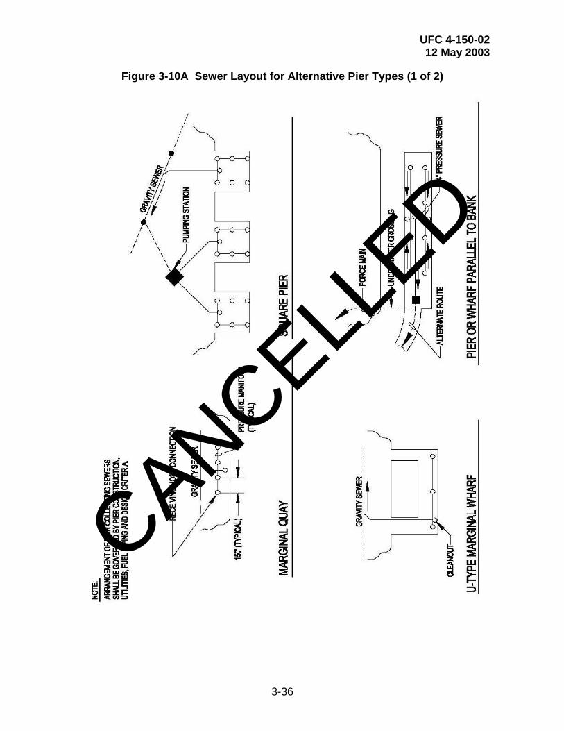
UFC 4-150-02 12 May 2003
3-36
Figure 3-10A Sewer Layout for Alternative Pier Types (1 of 2)
CANCELLED
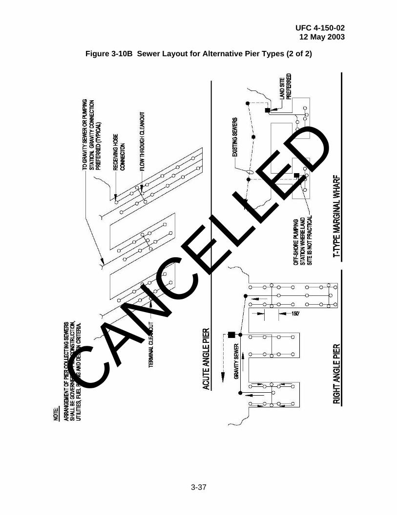
UFC 4-150-02 12 May 2003
3-37
Figure 3-10B Sewer Layout for Alternative Pier Types (2 of 2)
CANCELLED
UFC 4-150-02 12 May 2003
3-38
3-7.3.3 Location Details. See Figure 3-11 and Figure 3-12 for typical installation on piers and quay walls. Locate all collecting sewers behind the permanent wharf or pier construction and away from the fender systems. Locate pump stations off the pier and behind the bulkhead lines. If location along the pier deck is required, then do not restrict working area on the pier. Lines behind wharves should always be buried. For design of new piers and quay walls, consider locating sewers in utility tunnels. This arrangement will reduced external corrosion and improved maintainability of the sewer lines, and thus may offset higher construction costs.
3-7.3.4 Environmental Considerations (Corrosion and Freeze Protection).
• Evaluate paint and finish requirements. See paragraph 2.6. For ship-to-shore sewer connections (including ductile iron sewer pipe and all exposed metal such as steel support members, gratings, angles, pipe support hangers, fastening devices, and other appurtenances) it is generally recommended to provide a two-coat, coal-tar epoxy coating, conforming to Steel Structures Painting Council (SSPC) Paint No. 16. Specify a total dry film thickness of 0.4 mm (16 mils) minimum.
• Evaluate freeze protection requirements. See Figure 3-13. Pipes installed under piers or wharves in any geographic location must be protected from wave action and floating objects. Provide protective jacketing of the insulation using aluminum, stainless steel, or coal-tar epoxy coated steel where freeze protection is required. Provide structural protection for the entire length of pipe run in addition to jacketing. Use steel cage of fabricated shapes or consider the use of a catwalk system that would provide both access and piping protection. Specialized freeze protection features are defined in Chapter 6.
CANCELLED

UFC 4-150-02 12 May 2003
3-39
Figure 3-11A Typical Sewage Collection Facilities (1 of 2)
CANCELLED

UFC 4-150-02 12 May 2003
3-40
Figure 3-11B Typical Sewage Collection Facilities (2 of 2)
CANCELLED
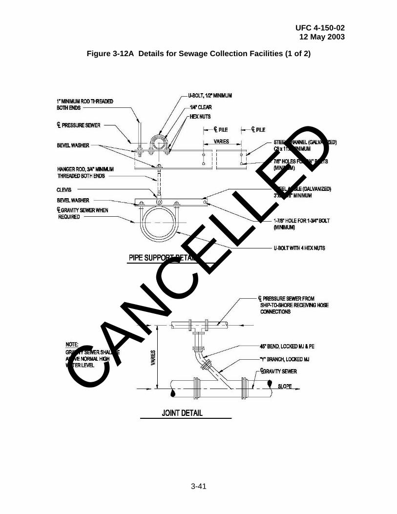
UFC 4-150-02 12 May 2003
3-41
Figure 3-12A Details for Sewage Collection Facilities (1 of 2)
CANCELLED

UFC 4-150-02 12 May 2003
3-42
Figure 3-12B Details of Sewage Collection Facilities (2 of 2)
CANCELLED
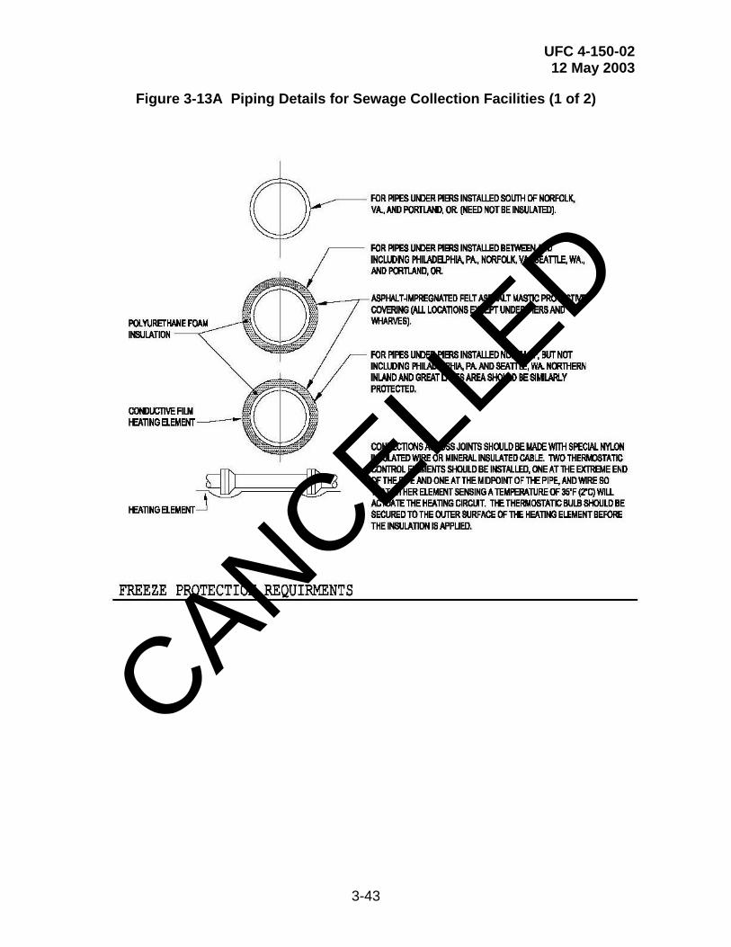
UFC 4-150-02 12 May 2003
3-43
Figure 3-13A Piping Details for Sewage Collection Facilities (1 of 2)
CANCELLED

UFC 4-150-02 12 May 2003
3-44
Figure 3-13B Piping Details for Sewage Collection Facilities (2 of 2)
CANCELLED

UFC 4-150-02 12 May 2003
3-45
3-7.3.5 Odor/Septicity Control. Slope sewer pipes as much as possible to minimize detention time. Provide aeration in accordance with sound engineering practices. Holding tanks must be aerated unless detention time is less than 3 hours at average 24-hour flow. Keep force mains as short as possible and avoid sulfide generation. Control sulfide generation by using an injection of oxidizing chemicals such as chlorine, permanganate, or hydrogen peroxide. Consult suppliers of chemicals feed equipment regarding costs and expected performance. Refer to WEF MOP FD-5, Gravity Sanitary Sewer Design and Construction, for rational methods to predict sulfide generation rates and methods of control. Maintain minimum flow velocity of 0.9 m/s (3 ft/s). Provide cleanouts and air relief valves at strategic and accessible locations. Provide check valves at pump stations.
3-7.3.6 Structures and Appurtenances. Some sewer structures and appurtenances have already been defined in Figure 3-11, Figure 3-12, and Figure 3-13. Additional features are defined in Figure 3-14, and Figure 3-15. Also, see Table 3-6.
3-7.3.7 Pump Stations. The design of sewage pump stations at waterfront facilities requires the careful consideration of all associated parameters including the premium value of real estate. The system must account for all ship flows and the connection to the station's central sewage distribution system. Careful coordination is required with the Activity and the cognizant NAVFAC EFD/EFA OR USACE DISTRICT. It is imperative to provide a properly operational system at minimum construction cost and operational cost while optimizing the use of waterfront property.
3-7.3.8 Pipe. A variety of pipe materials may be acceptable to specify and will vary on a pier-by-pier basis. Consult with the Activity and the cognizant NAVFAC EFD/EFA OR USACE DISTRICT for the final material selection. In general, PVC pipe may be used for gravity systems. Ductile iron pipe is preferred for pressurized systems. However, PVC pipe and HDPE pipe has been specified for pressurized systems at some pier facilities. Lined ductile iron with mechanical joints should be used for exposed locations and where high impact resistance is important. Support exposed pipe in accordance with manufacturer’s recommendations. In other exposed locations where corrosion resistance is a major concern, consider specifying thermoplastic (high density polyethylene) pressure pipe with butt fusion joints. Plastic piping on pier and wharf systems should be protected from impact by floating debris and other hazards. In these cases, consider a specially designed utility trench. For buried lines, apply general sewer pipe selection guidelines. CANCELL
ED
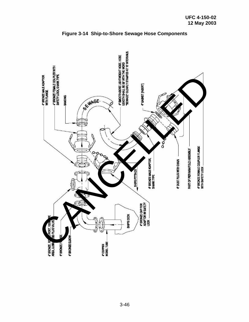
UFC 4-150-02 12 May 2003
3-46
Figure 3-14 Ship-to-Shore Sewage Hose Components
CANCELLED

UFC 4-150-02 12 May 2003
3-47
Figure 3-15 Above Pier Hose Connection
CANCELLED

UFC 4-150-02 12 May 2003
3-48
Table 3-6 Special Pier Structures and Appurtenances
STRUCTURE OR APPURTENANCE
WHERE TO USE
DETAILS
REQUIREMENTS
In-line Cleanout Note 1 See Figure 3-12
Regular Manhole Note 2 Refer to NFGS-02530, “Sanitary Sewerage”
Note 3
Drop Manhole Note 4 Refer to NFGS-02530 Note 5
Siphons Note 6 Note 7 Note 8
Intercepting Sewers Note 9 Note 10
Traps and Interceptors Note 11 Note 12
Terminal Cleanout Note 13 See Figure 3-12 Note 14
Receiving Hose Connections
See Figures 3-14 & 3-15 Note 15
Sewer Pipe Supports Note 16 See Figures 3-11 & 3-13
NOTES TO TABLE 3-6
1. Use in-line cleanout at junctions and changes of direction and when required according to spacing shown in details under regular manhole below.
2. Use regular manhole: terminally on all lines; at all junctions and changes of direction; at changes in invert elevation or slope. Otherwise, according to spacing shown below:
Pipe Size Maximum Spacing Inches (mm) Feet (m) 18 (450) or less 400 (120) 18-48 (450-1200) 500 (150) 48 (1200) and greater 600 (180) 3. Requirements for regular manholes: lower invert through manhole a distance equal to expected
loss of head in manhole, plus 0.8 times any change in sewer size. For junction manholes, check which upstream invert is critical in determining outlet invert. Raise top of manhole above possible flooding level.
4. Use drop manhole when difference between inlet and outlet inverts exceed 0.6 m (2 ft).
5. Requirements for drop manholes: for difference less than0.6 m (2 ft), increase upstream sewer slope to eliminate drop.
CANCELLED

UFC 4-150-02 12 May 2003
3-49
Table 3-6 (Continued) Special Pier Structures and Appurtenances
NOTES TO TABLE 3-6
6. Use siphons for carrying sewers under obstructions or waterways.
7. For siphons: maintain velocity of 3 fps (0.9 m/s). Use no less than two barrels with minimum pipe size of 6 inches (150 mm). Provide for convenient flushing and maintenance.
8. Requirements for siphons: use WEF MOP FD-5 for hydraulic design.
9. Use intercepting sewers where discharge of existing sewers must be brought to a new concentration point.
10. Requirements for intercepting sewers: take special care against infiltration due to depth or proximity of surface water.
11. Use traps and interceptors on all outlets from subsistence buildings, garages, mechanical shops, wash pits, and other points where grease or oil can enter the system.
12. For traps and interceptors: use a displacement velocity of 0.05 fps (0.015 m/s). Grease removal: in absence of other data use 300 to 400 mg/L. Provide for storage of 1 week's grease production (1 day if continuous removal is provided). Length = twice depth.
13. Use terminal cleanouts terminally on all pier collection systems.
14. Requirements for terminal cleanouts: locate where it will not interfere with other operations on the pier or other utilities.
15. Requirements for receiving hose connections: design connections to receive the discharge from ships.
16. Properly support all sewer pipes, especially pipes located under the pier. See paragraph 2-4.1.3.
CANCELLED

UFC 4-150-02 12 May 2003
3-50
3-7.3.9 Sewage Transfer Hoses. See Figure 3-14 and Figure 3-15. Provide a washing facility for washing the end couplings and the exterior of the hose. The facility should include hot potable water and a standard stock detergent. Hose washing/storage facilities must be designed so that manual lifting or pulling of hoses is minimized through the use of mechanical devices and/or arrangement of the area. Caps for each end of the hose should be provided and installed after washing. The clean hose should be stored in drying racks. For further information, refer to NAVFAC MO-340, “Ship-to-Shore Hose Handling Operations Manual”.
3-7.4 Drydock Facilities. For drydock facilities, design the sewage collection system for the maximum planned docking pattern and the designed peak flow conditions. Consider the following when designing drydock collection systems.
• Separation of hydrostatic leakage from drydock wastewater: The drydock wastewater is generally not contaminated and can be discharged directly to storm sewers or open water depending on regulatory conditions.
• Separation of ship's domestic wastes from the industrial wastes generated by drydock activities: These industrial wastes include leakage, precipitation runoff, and washdown that carries sandblasting residue and paint.
3-7.4.1 Layout. Ships fitted with collection-holding-transfer (CHT) should be connected to dockside sanitary sewers for CHT discharge. Ships without CHT should use scuppers and manifold connections to the ship's discharge points and then transfer to the sanitary sewer system. See Figure 3-16 for typical collection system layouts in drydock facilities.
3-7.4.2 Pump Station Features. Make capacity equal to that of maximum combined ship's discharge rate of ships in drydock. Furnish portable auxiliary pumping facilities when required. Refer to UFC 4-213-10.
3-7.4.3 Sewage Receiving Connections and Transfer Hoses. See Figure 3-17 for underground drydock receiving hose connections. Figure 3-15 is also applicable for aboveground drydock receiving hose connections. Aboveground receiving hose connections should be used whenever possible. See paragraph 3-7.3.9 regarding transfer hoses.
3-7.4.4 Special Structures and Appurtenances. See Figure 3-16 for typical cleanout locations for drydock sewers. Locate cleanouts in main sewer at a maximum spacing of 91 m (300 ft).
CANCELLED

UFC 4-150-02 12 May 2003
3-51
Figure 3-16A Typical Sewage System Layouts for Drydock Facilities (1 of 2)
CANCELLED
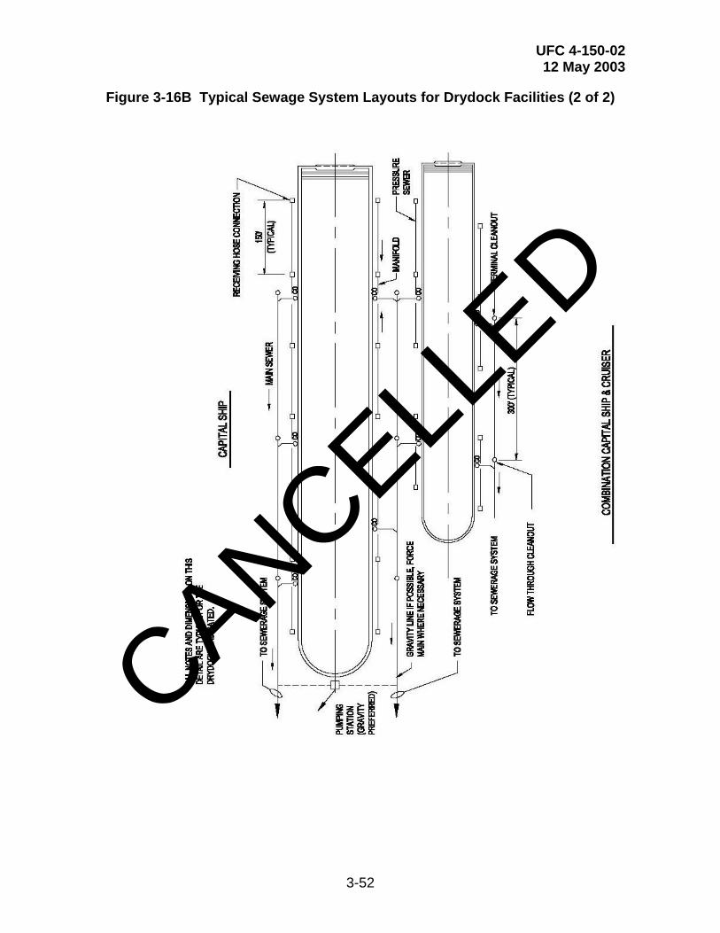
UFC 4-150-02 12 May 2003
3-52
Figure 3-16B Typical Sewage System Layouts for Drydock Facilities (2 of 2)
CANCELLED
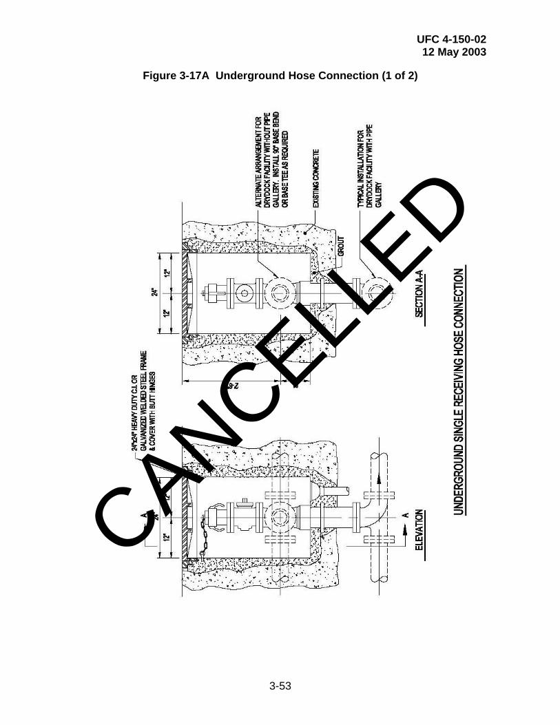
UFC 4-150-02 12 May 2003
3-53
Figure 3-17A Underground Hose Connection (1 of 2)
CANCELLED

UFC 4-150-02 12 May 2003
3-54
Figure 3-17B Underground Hose Connection (2 of 2)
CANCELLED
UFC 4-150-02 12 May 2003
3-55
3-8 ELECTRICAL SYSTEMS. Electrical power is required on piers, wharves, and at drydocks for ships services. This includes hotel service (shore-to-ship power), ship repair (industrial power), ships systems testing, pier weight-handling equipment, cathodic protection systems, pier lighting, and miscellaneous pier electrical systems. Materials and installation must conform to the requirements given in MIL-HDBK-1004 series, Electrical Engineering, and in NFPA 70, National Electrical Code. For drydocks, refer to additional criteria in UFC 4-213-10. Utility data and specialized technical data has been removed from this UFC and is available in the SCDB on the NAVFAC EICO website or it may be obtained directly from NAVFAC EICO or USACE.
3-8.1 Types of Electrical Services. Design electrical services for piers, wharves, and drydocks for one of the two types of service listed below, as directed by the cognizant Engineering Field Division / Activity (EFD / EFA).
3-8.1.1 Permanent Service. At naval stations, shipyards, repair piers, drydocks, and other continuously occupied waterfront facilities, provide fixed electrical substations and associated facilities to accommodate the normal, maximum electrical demand load. The design may include the use of portable substations as necessary to provide the peak electrical load that may result from abnormal and unplanned electrical needs. The electrical design must include: (1) ships power requirements (hotel services) on a dedicated un-grounded power system; and (2) other facility loads on a separate grounded power system that includes loads such as lighting, weight-handling equipment, cranes, pumps, general utilization power, and the industrial power system (dedicated for ship’s repair work while berthed) when required. There are three basic types of fixed substation installations: (1) the substation is installed on the lower deck of a double-deck pier; (2) the substation is installed on the pier deck of a single-deck pier or at grade level adjacent to the pier or associated waterfront facility, and (3) the substation is installed in an electrical vault located below the pier deck. The vault system has been used on many existing piers, however it is not recommended for new installations and requires approval of NAVFAC EICO or USACE. See Appendix E and the section entitled “Substations” for additional information.
3-8.1.2 Temporary Service. Provide temporary electrical service at waterfront facilities not continuously occupied, or at any facility where a substantial portion of the peak load will be occasional or intermittent. Provide primary feeders and high voltage outlet assemblies (5kV and 15kV) for connections to portable substations. Examples of high temporary loads include: (1) power for testing certain ships weapons systems; and (2) power for testing ships plant nuclear systems. That portion of the load serving basic pier, wharf, or drydock functions (lighting, weight-handling equipment, and receptacles not related to ship service or repair service) must be fed from the permanent service.
3-8.2 Primary Power System. The primary distribution system on the pier or other waterfront facility normally operates in the medium-voltage range between 5 kV and 35kV and will depend upon the shore-side utility voltage(s) available. The shore-side utility system is normally already in existence. It may have to be expanded or upgraded to support a new or increased capacity pier, but will rarely require a completely new electrical utility service point. Upgrades to the system should provide
CANCELLED
UFC 4-150-02 12 May 2003
3-56
the pier with a dedicated normal circuit and provisions for switching to a backup circuit. The Activity is responsible for providing justification for alternate primary feeders and standby power services required for essential operations. Special electrical primary systems may be required for certain classes of ships. These specific requirements are included in SCDB. Provide selective coordination between system equipment components to ensure minimized downtime of ships systems due to external or internal electrical system faults. Refer to MIL-HDBK-1004/1, Electrical Engineering, Preliminary Design Considerations, for a description of the different types of distribution systems.
3-8.2.1 Pier, Wharf, or Drydock Primary Systems. For permanent service, provide dual primary feeders from the shore primary system to the switching stations or substations serving the ships’ hotel services and industrial loads. For temporary service, provide dual primary feeders from the shore primary system to strategic locations that serve portable substations. Conduits, ductbanks, and manholes cast integrally with the pier structure are preferred for new piers. Conduits on piers may also be installed in dedicated electrical trenches or in piping trenches that serve other utilities. To avoid damage to the conductor's insulation, electrical conduits should not be placed in close proximity to steam piping. Refer to Chapter 2 for general protection requirements.
3-8.3 Secondary Power Systems. The secondary electrical distribution system is evolving to higher voltages as the power demand on the ships continues to increase. It must be designed with the flexibility to serve the various classes and categories of ships that are anticipated to utilize the facility.
3.8.3.1 Ships Power. Historically, the electrical system providing power for most ships has been a dedicated 480 volts (nominal), three-phase, 60 Hz, ungrounded system. This system has been supplied from substations located on piers (or at the head of the pier for shorter piers), and connected through dedicated receptacles located at the perimeter of the pier, wharf, or drydock. Currently, 4,160 volts (nominal), three-phase, three-wires, 60 Hz power is required for later class nuclear aircraft carriers (CVN 68 class and higher). These carriers are sometimes capable of accepting 480-volt power as well. Future classes of ships (surface combatants and amphibious assault) are expected to require 4,160 volts (nominal), three-phase, three-wires, 60 Hz power. Future CVN class ships are expected to require 13,200 volts (nominal), three-phase, three-wires, 60 Hz power. In general, the pier electrical distribution system must be designed to limit the fault current contribution from the shore power, at the ship’s bus, to 100,000 amps (rms) at 480 volts.
3-8.3.2 Other Ships Power Requirements. When required, provide direct current (dc) power and 400 Hz power for ships service. These systems must be derived from portable rectifiers or conversion equipment provided by the Activity. Provide an electrical power connection system that is supplied from the pier’s permanent / industrial power system rated 277/480 Volts, three-phase, four-wires, grounded, 60 Hz. These special power systems must not be connected to the ships’ dedicated hotel power service(s).
CANCELLED

UFC 4-150-02 12 May 2003
3-57
3-8.3.3 Permanent Pier Loads and Industrial Power. Other electrical requirements such as pier lighting, receptacles, weight-handling equipment and industrial power must be supplied from dedicated 480Y/277 Volt transformers. Industrial power is defined as power specifically for equipment utilized for the repair and overhaul of ships at berth and is normally only required in naval shipyards. Do not provide permanent pier load power or industrial power from the same transformers providing shore to ship hotel power.
3-8.4 Location and Arrangement of Equipment. Final locations of equipment must be made on a pier-by-pier basis in concurrence with the Activity and the cognizant NAVFAC EFD/EFA OR USACE DISTRICT. Selection must be coordinated with the pier design type, other pier utilities and the pier’s operational requirements. In general, provide as much clear space for cranes and vehicular traffic on the pier deck as possible. Examples of pier equipment arrangements are shown in Figure 3-18.
3-8.4.1 Substations. The three main types of arrangements for substations are discussed in the following subparagraphs with an example of their use, where appropriate.
3-8.4.1.1 Double-deck Piers. On a double-deck pier, the upper deck is used for conventional pier functions while the lower deck serves utility systems and utility connections. The electrical service for a double deck pier should be a permanent service. The substations should be located on the lower deck and may be symmetrically arranged around the pier centerline. Cross sections of a double-deck pier are shown in Figure 2-2.
One recent example of substation arrangement and power distribution system is Pier 6 at the Norfolk Naval Base (NNB). It consists of two electrical service clusters with each service cluster consisting of four 4,000 kVA unit substations, totaling 32 mVA. The output of these substations serves fixed low voltage outlet assemblies. These outlets are defined on the Pier 6 project drawings as “shore power stations” (SPS). Each SPS contains 12 sets of three, single pole, low voltage cable connectors (36 connectors total) that in turn serve the shore-to-ship service cables. Illustrations of the electrical system for the NNB double-deck Pier 6 are shown in figure D-1. Pier 6 was designed as a general berthing pier to support all ship classes except SSN and CVN, and may not be directly applicable for double-deck SSN and CVN piers or piers designed for specific ships. See paragraph entitled ”Connectors” for additional information on the various types of connectors currently being used. CANCELL
ED
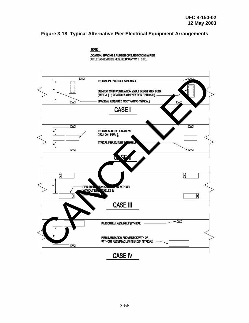
UFC 4-150-02 12 May 2003
3-58
Figure 3-18 Typical Alternative Pier Electrical Equipment Arrangements
CANCELLED
UFC 4-150-02 12 May 2003
3-59
3-8.4.1.2 Single Deck Piers. On a single deck pier the substation can be deck mounted or at grade level adjacent to the pier. The unit substation illustrated in the vault system in Figure D-2 could also be utilized in the pier deck mounted or grade level installation system. In either installation method, the unit substations are outdoor construction. The deck mounted/grade level substations may include walk-in aisle features, however they are not recommended when located on the pier due to the significant increase in size.
3-8.4.1.3 Existing Pier Vaults. Many existing Pier’s utilize the electrical vault system. This system is described in Figure D-2. This type of electrical service, commonly used on many existing piers, is not authorized for the design of new piers without approval from NAVFAC EICO or USACE. It was based upon electrical vaults located below the pier deck that were designed as an integral part of the pier’s structural system. The vaults house secondary unit substations and may also contain primary switching equipment. The vaults require proper ventilation, pumping systems, and an access system integrally designed into the pier’s deck. This type of electrical system has four significant disadvantages: (1) the vaults are considered to be a “confined space”; (2) the vaults are subject to flooding; (3) the vault’s environment is excessively caustic to the electrical equipment, even under normal conditions; and (4) replacement of a unit substation creates significant interference to pier operations and results in deck pavement removal and replacement
When a vault system is used, the substation vaults must be ventilated and flood resistant for protection of the electrical equipment. Prevent flooding with dual sump pumps that discharge at a point above highest tide. Provide a "float switch and alarm system" to alert personnel of sump pump failure and high water level. The sump pump power must be connected to a source other than the vault substation. That source must remain energized when the pier electrical hotel service power and permanent / industrial power systems are turned off. Freeze protection must be provided in climates where any element of the pumping system could freeze. Ventilation cooling must be provided with air quantity based upon the highest site temperature and the highest vault temperature that can be tolerated by the electrical equipment. One approved method of vault ventilation is shown in Figure D-2. Separate ventilation air intake and exhaust louvers by as much distance as possible. They may be on opposite sides of the pier if the ventilation ducts are above high tide. Provide an access system for the electrical vault that includes personnel access and equipment replacement access. Personnel access usually consists of manhole frame with cover and vertical ladder. Equipment access systems are a significant structural element that are required to withstand vehicular traffic and must be designed as an integral part of the pier deck.
3-8.4.2 Outlet Assemblies. The number of electrical shore service stations, their location aboard ship, the per station ampacity, and appropriate voltage for each ship are defined in SCDB. For a general discussion of methods to be used to establish shore utility station spacing on piers and wharves, refer to Chapter 2. For spacing at drydocks, refer to UFC 4-213-10.
CANCELLED

UFC 4-150-02 12 May 2003
3-60
3-8.4.3 Cable Lengths. Most ships have to be served from multiple 400A circuits. Design the electrical system such that cable lengths from the substation to the outlet assemblies in the parallel circuits are approximately equal (within 10 percent).
3-8.4.4 Combined Equipment. Electrical substations and outlets may be consolidated in an integral package, with the receptacles placed in the side (or sides) of the substation enclosure. These consolidated outlet assemblies may be spaced as necessary along the pier or drydock perimeter. See Figure 3-18, cases III and IV.
3-8.4.5 Outlet Assemblies for Portable Equipment. When supplying ships loads from portable substations, locate primary outlet assemblies in the same manner as required for regular outlet assemblies. Primary outlet assemblies, provided for temporary services that supplement permanent substations, should be placed in the vicinity of their intended use. Coordinate these locations with the Activity and the cognizant NAVFAC EFD/EFA OR USACE DISTRICT.
3-8.5 Distribution System Equipment and Materials. Equipment and materials selected for waterfront electrical systems must be coordinated with the cognizant NAVFAC EFD/EFA OR USACE DISTRICT and the standards and preferences of the Activity. Since significant technical information for many of the distribution system components is available in the Unified Facilities Guide Specifications (UFGS ) Sections 16360, Secondary Unit Substations, 16341 SF6 Insulated Pad-mounted Switchgear and 16442 Switchboards and Switchgear, the nomenclature and requirements for the equipment must be thoroughly coordinated in the project documentation (plans and specifications).
3-8.5.1 Fixed Substations for 480 Volts Service. There are several methods for providing substations for permanent 480 volts services on piers. Based on the overall system design, the substation should contain primary, secondary, auxiliary, and transformer sections. See Appendix D. The primary section would either contain the primary overcurrent protection features, a disconnect switch, and a service circuit selector switch if the system includes multiple primary circuits, or it would be limited to the primary circuit terminations if separate pad-mounted primary switchgear is used. There must be separate 480 volts secondary unit substations designated for the ships hotel loads and for the other pier loads including industrial power (if required). The main transformers should be of the liquid-cooled type, standard three-phase, 480 volts, with four full-capacity, 2-1/2-percent taps, two above and two below the nominal primary voltage rating unless actual operational conditions require other tap settings. Maximum transformer rating should be 4000 kVA. Substations, including transformers should be stainless steel with a paint coating system in compliance with ANSI C57.12.29. If specific operational conditions require parallel operation with the shipboard generators, coordinate with the cognizant EFA / EFD and NAVSEA to determine the additional features that must be added to the equipment. In these cases, the shipboard generator and other equipment ratings are available upon request from NAVSEA.
3-8.5.1.1 Shore Power Circuit Breakers. The equipment should provide 480 volts (nominal), three-phase, 60 Hz power, as defined in NEMA C84.1, Voltage Ratings for
CANCELLED
UFC 4-150-02 12 May 2003
3-61
Electrical Power Systems and Equipment (60 Hz), voltage range "A." via low voltage power circuit breakers. These should be electrically operated, drawout-type units, with adjustable trip features. Integral current-limiting fuses may be required depending on the fault current contribution from the substation transformer and the specified short circuit rating of the breaker. Provide one 600 volts, 800 amp frame circuit breaker for each individual 500 amp shore power receptacle. Use either 400 A or 600 A sensors per activity requirement. (Note: OPNAV Inst 111310.3A requires that the overcurrent setting be 440 A. To provide this setting a 400 A sensor with a 1.1 pickup is needed. However, prior to specifying this equipment, verify that more than one circuit breaker manufacturer can provide this setting. The most common combination available is 600 A sensors with .75 or .8 pickups which provide 450 A or 480 A overload settings).
3-8.5.1.2 Breaker Remote Operation. Breakers for ships service must include remote operation. This can be accomplished either by pushbutton stations which are integrally mounted in the electrical outlet assemblies, or by local breaker control switches at the substations. Coordinate with the standard practice of the local activity.
3-8.5.1.3 Space Heaters. Space heaters should be incorporated within individual substation sections in order to prevent condensation.
3-8.5.2 Substations for 4160 or 13,800 Volts Service. Provide substations with a secondary voltage of 4160 or 13,200 volts (nominal, as defined in ANSI C84.1, voltage range "A), when required by SCDB for the classes of ships to be berthed. System design should be such that the respective voltage (plus or minus 5 percent) is provided at the shore service receptacles. Design of primary unit substations is similar to fixed 480 volt substations except for voltage classifications and outlet assembly provisions. Circuit breakers should be 5 kV vacuum drawout type, with interrupting current rating based on available fault, and should be key interlocked with the primary receptacles (to prevent use of receptacles unless respective breakers are open).
3-8.5.3 Portable Substations. See Figure D-3. The pier design must include space allocation for the portable substations and provide the electrical primary distribution system required to energize the portable substations. This includes primary circuits, their disconnect switches, and the primary outlet assemblies. Design is similar to fixed substations except for portability provisions.
3-8.5.4 480-Volt Outlet Assemblies. 480 Volt outlet assemblies (receptacles and cable connections) vary with Activities but should be standardized on a Station-by-Station basis. Additional information on the outlet assemblies and the actual operational procedures used on the piers is available in MIL-HDBK-1025/10, Safety of Electrical Transmission and Distribution Systems, Section 9, “Shore-to-Ship Electrical Power Connections”. Detailed specifications for the outlet assemblies are also included in guide specification UFGS-16145, 480 Volt Pier Power Outlet Assemblies.
3-8.5.4.1 Receptacles. Ships hotel service receptacles must be provided in weatherproof, corrosion-resistant pier outlet assemblies, or combined with the
CANCELLED

UFC 4-150-02 12 May 2003
3-62
substations. Provide the number of receptacles required to serve the specific ship types and classes in accordance with SCDB.
There are currently two types of ships’ hotel service receptacles being used. Many existing facilities utilize a three pole, 500 amp receptacle in accordance with Mil Spec MIL-C-24368/1. A typical MIL-C, three-pole outlet assembly is illustrated in Figure D-4. Other facilities utilize a single-pole, 500 amp receptacle, grouped in a cluster of three. Typical details of the single-pole receptacle system are shown in Figure D-1.
3-8.5.4.2 Connectors. Cable connectors are available in two types: (1) one single, multiple conductor type (1-3/c cable); and (2) single conductor type grouped in a cluster of three (3-1/c cables). A typical three-conductor outlet assembly is illustrated in Figure D-4. Figure D-1 illustrates the single-conductor type connector.
NOTE: OPNAVINST 11310.0A requires that all low-voltage cables will be terminated with a MIL-C-24368/1 plug at each end of the cable. However, a waiver to this requirement has been requested and approved at certain locations by NAVFAC. This waiver permits the use of single-pole, 500-amp receptacles and single conductor connectors grouped in a cluster of three. OPNAVINST 11310.3A is being revised to address this optional connector system.
3-8.5.5 Primary Outlet Assemblies. Primary voltage outlet assemblies must have weatherproof, corrosion-resistant enclosures and high voltage connectors. Connectors must match the standard primary voltage coupler in use by the Activity and as required by the cognizant NAVFAC EFD/EFA OR USACE DISTRICT. Disconnects should have an interlocking key which can only be removed when the switch is opened. Design should be such that, after the disconnect has been opened, the interlocking key must be used to unlock and make possible the insertion or removal of the corresponding primary voltage pier coupler plug. Provide 500 amp coupler receptacles at each 4160 and 13800-volt pier outlet assembly. Incorporate outlet assemblies into substations as applicable. See Figure D-5 for typical 15 kV details.
3-8.5.6 Coordination of Shipboard Phase Rotation. Shipboard alternating current systems have a standard phase rotation. To minimize the phasing procedure and to reduce the time required to connect shore-to-ship power cables, shore power connectors should be phased so that they are compatible with the shipboard system. Refer to NAVSEA 59300-AW-EDG-010/EPISM, Section 2, Group E, Sheets 14 and 15, to determine phase rotation required for shore power connections.
3-8.5.7 Conduit Systems. For electrical conduit exposed under or on a pier, wharf, or drydock, evaluate the relative advantages of Schedule 80 PVC, and fiberglass-reinforced epoxy conduit. Avoid the use of PVC where they will be exposed to sunlight and moving objects. Although PVC Coated steel conduits have been used on many piers, the alternatives are more attractive economically and from a durability standpoint. The potential exists for loss of integrity of the PVC Coating systems in the harsh and corrosive environment. Fiberglass cable trays may be used in lieu of conduit
CANCELLED

UFC 4-150-02 12 May 2003
3-63
where adequately protected from physical damage and the elements. Provide stainless steel or fiberglass hangers and bolts. Coordinate with the requirements in paragraph 2-4.1.3.
3-8.5.8 Cables For Shore-to-Ship Service. Shore-to-ship cables are normally provided by the Activity. For 480 volts, three-phase, three-wire service, cables should be ungrounded, standardized lengths of single cable with three conductors, Type THOF-500, conforming to military spec MIL-C-915/6, Cable Power Electrical, 600 Volts, For Outboard Use Only, and should be used for loads not exceeding 400 amps. For 4,160 volts, three-phase service to nuclear aircraft carriers, cables should be SHD350GC 8 kV, non-shielded insulated, PVC-jacketed cable, in accordance with Insulated Cable Engineers Association (ICEA) S-66-524, Cross-Linked-Thermosetting Polyethylene-Insulated Wire and Cable for the Transmission and Distribution of Electrical Energy.
3-8.6 Ships’ Shore Power Requirements. SCDB provides a listing of shore electrical loads of ships while homeported or undergoing alteration and repair. Substation and feeder sizing on piers and wharves must be based upon the electrical loads given in the "Design Load" for the largest ship (or largest number of ships) of all classes which could be berthed at the pier. The minimum number of receptacles provided in a secondary outlet assembly should match the number of receptacles in the ship’s respective receptacle stations. Nested ships must also be considered in the electrical outlet assembly design where indicated by the facility berthing plan or where conceivable at a future date.
3-8.6.1 Alternating Current Power. Hotel service loads include the ship's electronics, weapons systems, cargo booms, galley equipment, space heating, and miscellaneous lighting and power loads. These loads are supplied with either 480 volts (nominal) or 4160 volts (nominal) ungrounded power. The 480 volts system should supply approximately 480 volts at no load and 450 volts (plus or minus 5 percent) under loaded conditions and at the ship's load center. For 4160 volts requirements, supply approximately 4160 volts at no load and 4100 volts (plus or minus 5 percent) under loaded conditions and at the ship's load center. System design must be coordinated with the planned nesting requirements of the pier to maintain the voltage within the allowable tolerances at outboard ships.
3-8.6.2 Direct Current (dc) Power. When required, dc power should be provided for certain ships in accordance with instructions provided by the Activity. Portable rectifier units will be provided by the Activity. Provide sufficient ac power and receptacles to serve such equipment. Coordinate connection requirements with the Activity.
3-8.6.3 400-Hz Power. 400-Hz power for ship service may be supplied from the 480 volts system utilizing portable generating equipment furnished either by the Activity or by the ship. Provide 60 Hz power and receptacles to serve such equipment. Coordinate connection requirements with the Activity.
CANCELLED
UFC 4-150-02 12 May 2003
3-64
3-8.6.4 Shipboard Equipment Ratings. Most ship distribution circuit breakers operate at 440 volts and are protected with 100,000-amp, current-limiting fuses in series with the breakers. In most cases, these circuit breakers are type AQB-LF400 as described in NAVSHIPS Publication 362-2333, Air Circuit Breakers (Fused), Navy Type AQB-LF400. The main breaker for the shipboard system on nuclear carriers is an air-type breaker rated at 250,000 amps asymmetrical interrupting capacity, and without current-limiting fuses. The shore distribution system must be designed in accordance with MIL-HDBK-1004 series, Electrical Engineering, to ensure that available fault is within the capability of the ship’s distribution system. Contact the cognizant NAVFAC EFD/EFA OR USACE DISTRICT for information on shoreside fault current data to determine the required interrupting capacities and equipment design characteristics.
3-8.7 Supplemental Requirements for Nuclear Submarines (SSN, SSBN). Nuclear submarines (SSN, SSBN) should conform to the following shore power requirements:
3-8.7.1 Substations for 480 Volts Service. Substations serving hotel loads at submarine piers must be designed in accordance with paragraph 3-8.5.1 for fixed substations, or paragraph 3-8.5.3 for portable substations, and in accordance with the supplemental requirements below. The substation's primary section should be built with dual primary feeders. Switchgear and breaker equipment should be designed so that automatic reset and restoration of power to submarine services will be delayed a minimum of 5 to 10 seconds after loss of commercial power. This is required in order to prevent damage to the submarine's electric plant equipment. The maximum time to restore power should be 5 minutes. Provide undervoltage and underfrequency relays at substations. Relay types and set points for undervoltage and underfrequency should be evaluated separately for each installation and coordinated with the cognizant NAVFAC EFD/EFA OR USACE DISTRICT.
3-8.7.2 Standby Power. Power requirements for normal operation are given in SCDB. A permanent standby generator plant sized to provide all submarines at a pier with emergency power for normal hotel demands should be provided at active berths. One spare generator for each plant should be supplied. The generator plant is not required at ports-of-call. The generator plant should incorporate automatic load shedding and load priority selection features. Generator plants should be located ashore whenever possible.
3.8.7.3 Maximum Downtime. At facilities where submarines are berthed, the station's electrical utility system and the pier's electrical system should be designed to provide a maximum downtime of 5 minutes using temporary or emergency generators, or an alternate commercial feeder. System downtime is defined as: (1) the time required to restore power to the pier when maintenance or repair activities are required; or (2) the time required to transfer from one power source to another after system disturbances. This includes the time required for protective devices to operate and the time to start emergency generators.
CANCELLED

UFC 4-150-02 12 May 2003
3-65
3-8.7.4 Super Shore Power. SCDB lists “super shore power” requirements for nuclear submarines. Super power is required for the ship's testing, checkout, and refueling operations. These super shore power requirements are in addition to the normal power requirements. Provide super power from a separate substation that supplies no other loads. Portable substations connected to temporary service outlets are recommended for this service. Extend primary service and provide connections for these portable substations. The special requirements for submarine piers given in subparagraphs 3-8.7.1, 3-8.7.2, and 3-8.7.3 above do not apply to super shore power.
3-8.8 Ground System. Provide a ground system at piers, wharves, quaywalls, and other waterfront structures that measures not more than 5 ohms for all permanent electrical equipment. Ground systems should be in accordance with NFPA 70 except where it is required or recommended to be otherwise in this UFC or by the project documentation. Stranded-copper-wire ground conductors, sized in accordance with NFPA 70, should be used to interconnect equipment enclosures and the ground system. Several methods of ground systems are typically used on Navy piers and are identified below as examples. These methods tie into an “onshore ground rod system” at the head of the pier. Where an “onshore ground rod system” is not applicable, an “alternative ground” system as indicated below, must be utilized.
3-8.8.1 Water Piping Ground. The metallic water piping on a structure can be used as a ground for electrical-equipment enclosures on the structure. However, the effect of this usage on the cathodic protection system (if present) for the water mains must be explored. If adverse effects are possible use a different method.
3-8.8.2 Pier Structure Ground. The pier structural steel system may be used as part of the grounding system for electrical equipment enclosures on the structure. This method, utilized on the double-deck Pier 6 Replacement Project in Norfolk, connected exothermically welded # 4/0 bare copper conductors from the structural steel rebar to threaded 13 mm (1/2 in) inserts. These inserts were located near the electrical equipment, as required, throughout the pier on the ceiling or walls. Ground bars or individual ground conductors were then attached to the inserts.
3-8.8.3 Alternative Ground. Where it is not practical to properly maintain an "onshore ground rod system" adjacent to a pier, provide metal plates laid under water and on the bottom of the associated body of water. The conductor connecting these plates should be at least No. 2 AWG stranded copper wire. In addition, ground systems for waterfront structures that have gasoline piping systems should be designed in accordance with MIL-HDBK-1022A.
3-8.9 Pier Lighting. Information on pier lighting is available in UFC 4-151-10, General Criteria for Waterfront Construction.
3-8.10 Lightning Protection. Provide lightning protection systems when required. Coordinate with the cognizant NAVFAC EFD/EFA OR USACE DISTRICT. Design in accordance with MIL-HDBK-1004/6, Lightning Protection, and NFPA 780,
CANCELLED
UFC 4-150-02 12 May 2003
3-66
Standard for the Installation of Lightning Protection Systems. Consider the protection of cranes, above deck substations, pier mounted buildings, and lighting system masts.
3-9 TELECOMMUNICATION SYSTEMS. The purpose of this section is to provide requirements for Base Level Information Infrastructure (BLII) Pier Connectivity Specifications, telephone service, and other telecommunications systems.
3-9.1 BLII Pier Connectivity. These guidelines are provided for planning, designing, engineering, and constructing new or repairing existing Navy piers. Figure 3-19 illustrates the three major components that are required to provide end-to-end connectivity to IT-21 compatible ships. They are the Pier Head ITN Building Node; the Pier Fiber Distribution Center, and the Fiber Optic Riser Panels.
3-9.1.1 Pier Head ITN Building Node. The Pier Head ITN Building Node is connected to the Base Area Network (BAN) and becomes the interface for adding additional piers to the infrastructure for SIPRNET/NIPRNET connectivity. At the time this document was prepared, Pier Head ITN Building Nodes have been installed or are in the process of being installed at the following activities: Naval Station Mayport, Submarine Base Kings Bay, Weapons Station Earle, Submarine Base New London, Naval Station Little Creek, and Naval Station Norfolk. Other stations will be added as the Navy Marine Corps Internet (NMCI) comes on line. A 144-strand hybrid fiber optic cable (72 multi mode and 72 single mode) is required between the Pier Head ITN Building Node and the Pier Fiber Distribution Center. This cable may already exist if the pier is being repaired; however, for new pier construction, the cable will need to be installed. The designer should coordinate with the local Information Technology (IT) group to ensure that the proper Pier Head ITN Building Node has been identified. All cabling and interconnections inside the Pier Head ITN Building Node are the responsibility of the local IT group unless other prior arrangements have been made.
3-9.1.2 Pier Fiber Distribution Center. The Pier Fiber Distribution Center provides a breakout point for the 144-strand hybrid fiber optic cable coming from the Pier Head ITN Building Node and the Fiber Optic Riser Panels. Figure 3-20 shows the fiber optic cable entering into the splice can from the Pier Head ITN Building Node. The fiber is spliced onto another 144-strand fiber optic cable (72MM/72SM) for submarine piers or 96-strand fiber optic cable (48MM/48SM) for surface ship piers. This is routed to the Environmental Distribution Center 1 (EDC 1) patch panel. Using internal patch cables, EDC 1 is patched to EDC 2. From EDC 2, a 144 or 96 strand hybrid fiber optic cable is routed to a second splice can where it is spliced to several 24-strand hybrid fiber optic cables (12MM/12SM) that run to the Fiber Optic Riser Panels. Figures 3-21 through 3-24 provide detailed information on the EDC 1 and EDC 2 patch panels located inside the Pier Fiber Distribution Center and their interconnections (note that the patch panels are shown for both surface ship piers and submarine piers).
3-9.1.3 Fiber Optic Riser Panel. The Fiber Optic Riser Panel is the interface for the ship to shore connectivity. The panel is provided with a 24-strand hybrid fiber optic cable (12MM/12SM) coming from the Pier Fiber Distribution Center. This provides a fiber optic receptacle, J1, to interface with the umbilical cable assembly that goes to the
CANCELLED

UFC 4-150-02 12 May 2003
3-67
ship (note that details on the J1 pigtail assembly may be found on NAVSEA drawing 7325760D). Figure 3-25 shows the Fiber Optic Riser Panel. Figures 3-26 and 3-27 show the patch panel connections inside the EDC for a surface ship and submarine respectively. Figures 3-28 and 3-29 show the rubber gasket cutouts for a surface ship and submarine respectively.
3-9.2 Telephone Systems. Provide a voice telephone distribution system to each berth on piers and at drydocks unless specifically instructed otherwise. Provision should be made for the telephone cable to be terminated in a telecommunications outlet assembly adjacent to each berth. Provide a Main Distribution Frame (MDF) at the shore end of the pier for the cross-connect devices. The assembly must include connectors mounted to the exterior of the enclosure. These connectors will be connected to the shore end of the ship-to-shore telephone cable. Commercial "dial tone" services and the telephone switching system is the responsibility of the Station’s Communications Officer.
3-9.2.1 Ships Demand. SCDB identifies the number of telephone pair shore lines required by each ship type. Cable sizes include the ship requirement, the appropriate embarked-staff requirement, and an allowance for spare pairs. Cable sizes have been rounded up to the next larger standard telephone cable. The pier telephone distribution cable system should be designed using the pier's berthing plan. Provide cable sizes based upon the worst case at each berth. Berths designed for nested ships should be provided with the total number of cables indicated for all ships in the nest.
3-9.2.2 Other Demand. Provide telephone service to security checkpoints and watchstand stations. These requirements may occur at the head and end of the pier, and at intermediate points along the pier. Coordinate with the Activity's security representatives.
3-9.2.3 Coin-Operated Telephones. When required, provide an independent conduit system to serve a vendor installed telephone cable which serves shipboard coin-operated telephones. Unless instructed otherwise, provide a conduit system at the head of the pier to support coin-operated telephones ashore (also to be vendor operated).
3-9.2.4 Location and Arrangement of Pier Telephone Distribution System. Each berth should be served by an independent run of conduit. The telecommunications outlet assembly must be an independent, freestanding structure. Outlet assemblies must be designed to prevent damage by ships lines and by traffic on the pier.
3-9.3 Other Telecommunications Systems. The need for the systems described below should be evaluated on a site-by-site basis. Provide these systems as directed by the Activity and the cognizant NAVFAC EFD/EFA OR USACE DISTRICT.
3-9.3.1 Dedicated Communication Circuits. Provide one 50.8 mm (2-in) conduit from the manhole or cross-connect cabinet at the head of the pier to each
CANCELLED
UFC 4-150-02 12 May 2003
3-68
telecommunications outlet assembly. This conduit must be dedicated for communication circuits that cannot use the telephone system.
3-9.3.2 Cable Television. Provide a conduit system (from the manhole at the head of the pier to each telecommunications outlet assembly) to support cable television requirements. Unless instructed otherwise, the cable television system will be provided by a commercial vendor. The designer must coordinate with the vendor and provide a complete raceway system.
3-9.3.3 Alarm and Signal Circuits. Provide two 31.7 mm (1-1/4 in) conduits (from the manhole at the head of the pier to each telecommunications outlet assembly) to serve alarm and signal circuits that cannot use the telephone system. Provide all conductors to serve these systems unless instructed otherwise. Coordinate with the Activity and the cognizant NAVFAC EFD/EFA OR USACE DISTRICT.
3-10 PIER POWER METERING SYSTEMS. Naval ships connected to shore power utilize a large percentage of the Navy’s infrastructure electricity. Many bases are now requiring the electricity usage to be measured and recorded. Since multiple circuits are normally used to provide the required capacity to the ships, often in a “nested” configuration, standard metering/ monitoring equipment may not be appropriate. There are however, commercial and government developed systems, including hardware and software, that are available. Coordinate with the cognizant EFD / EFA to determine if the Activity has a desired or required system that must be utilized.
3-10.1 Pier Power Monitoring System (PPMS). One of the power measurement systems available has been developed by the Naval Facilities Engineering Service Center (NFESC). The system is defined as the PPMS and consists of specialized embedded computer circuit boards, embedded software, and personal computer (PC) software that enable the Activity to measure, record, and study the electricity consumption and usage patterns of the connected ships. The PPMS was developed to be cost effective and to be easily installed. It involves the simple utilization of a conventional utility metering system. Typically, each monitored electrical outlet assembly will have one set of circuit boards. Battery backup features ensure that no data or operating software is lost when electrical power is disconnected. The data are sent to a central PC station. The PC can program the circuit boards and retrieve data. Parameters available on the PC are megawatt-hours and instantaneous values of amps, volts, power factor, and megawatts. Time-of-use (TOU) data are also available for the present 24-hour period. The PPMS correctly identifies the receptacles allocated to each ship and the total power consumed. Both the ship (customer) and the Activity (provider) can easily track shore supplied ship electricity. Software can be easily tailored to send the data directly from the PPMS to a master data collection and billing system. By providing complete energy use pattern information and consumption data, the PPMS enables Navy managers to educate, monitor, and encourage energy conservation for ships using shore supplied electricity. An operating PPMS demonstration system is presently installed on Pier 1 at Naval Station San Diego, CA.
CANCELLED

UFC 4-150-02 12 May 2003
3-69
3-11 OTHER SERVICES. Although their design is not covered by this UFC other services will occasionally be required at active and repair berthing facilities. Such systems include: jet fuel, chilled water, pure water, oxygen, acetylene, mapp gas, and inert gases. These services may be permanent or temporary (tank truck, gas containers or similar means) depending upon required quantity, location and economic considerations. The designer must consult with the Activity and the cognizant NAVFAC EFD/EFA OR USACE DISTRICT for specific instructions.
CANCELLED

UFC 4-150-02 12 May 2003
3-70
Figure 3-19 Block Diagram of Pier Structure
Figure 1: BLOCK DIAGRAM OF PIER INFRASTRUCTURE-NOT TO SCALE-
PIER HEADITN
BUILDINGNODE
EDC1 EDC2
FIBEROPTIC PIER
RISERPANEL
R2X
SHIP
FIBEROPTIC PIER
RISERPANEL
R1X
SHIP
FIBEROPTIC PIER
RISERPANEL
R2Y
SHIP
FIBEROPTIC PIER
RISERPANEL
R1Y
SHIP
12MM/12SMFiber Optic Cable
72MM/72SMFiber Optic Cable
Base AreaNetwork
Base AreaNetwork
PIER
INFR
AST
RU
CTU
RE
SHO
RE
INFR
AST
RU
CTU
RE
PIER FIBERDISTRIBUTION CENTER
AFL
OA
T
Umbilical CableAssemblies
CANCELLED

UFC 4-150-02 12 May 2003
3-71
Figure 3-20 Pier Fiber Distribution Center
Figure 2: PIER FIBER DISTRIBUTION CENTER DETAIL-NOT TO SCALE-
SPLICE
CAN
EDC 1 EDC 2
SPLICE
CAN
2-1/2" DUCTEnvironmental Distribution Center (EDC)Fiber Optic Patch PanelDim: 18.6"x16.6"x10.3"(SIECOR EDC-12P-NH)
Hoffman Enclosure Box w/Hinged Doors, 5.2' x 5' x 1'
Advance Splice Enclosure,Siecor P/N: SCF-6C28-01
6" Diameter x 28"48SM/48MM Strand for Surface Piers and72SM/72mm Strand for Submarine Piers
48SM/48MM Strand for Surface Piers and72SM/72MM Strand for Submarine Piers
12SM/12MM FiberOptic Cable
To Hoffman Enclosure Boxon Pier
To Pier Head ITN Node
B
BD
D
C
C
A
A
CANCELLED

UFC 4-150-02 12 May 2003
3-72
Figure 3-21 Pier Fiber Distribution Center EDC 1 Rear Detail Surface Pier
Figure 3: PIER FIBER DISTRIBUTION CENTER EDC 1 B-B REAR DETAIL - SURFACE PIERS -NOT TO SCALE-
F1 MM-X-A1
F2 MM-X-A1
F3 MM-X-A2
F4 MM-X-A2
F5 MM-X-A3
F6 MM-X-A3
F7 MM-X-A4
F8 MM-X-A4
F9 MM-X-A5
F10 MM-X-A5
F11 MM-X-A6
F12 MM-X-A6
F13 MM-X-B1
F14 MM-X-B1
F15 MM-X-B2
F16 MM-X-B2
F17 MM-X-B3
F18 MM-X-B3
F19 MM-X-B4
F20 MM-X-B4
F21 MM-X-B5
F22 MM-X-B5
F23 MM- X-B6
F24 MM- X-B6
F25 MM-X-C1
F26 MM-X-C1
F27 MM-X-C2
F28 MM-X-C2
F29 MM-X-C3
F30 MM-X-C3
F31 MM-X-C4
F32 MM-X-C4
F33 MM-X-C5
F34 MM-X-C5
F35 MM-X-C6
F36 MM-X-C6
F37 MM-X-D1
F38 MM-X-D1
F39 MM-X-D2
F40 MM-X-D2
F41 MM-X-D3
F42 MMX-D3
F43 MM-X-D4
F44 MM-X-D4
F45 MM-X-D5
F46 MM-X-D5
F47 MM-X-D6
F48 MM-X-D6
BLANK
BLANK
BLANK
BLANK
BLANK
BLANK
BLANK
BLANK
BLANK
BLANK
BLANK
BLANK
BLANK
BLANK
BLANK
BLANK
BLANK
BLANK
BLANK
BLANK
BLANK
BLANK
BLANK
BLANK
F1 SM-X-G1
F2 SM-X-G1
F3 SM-X-G2
F4 SM-X-G2
F5 SM-X-G3
F6 SM-X-G3
F7 SM-X-G4
F8 SM-X-G4
F9 SM-X-G5
F10 SM-X-G5
F11 SM-X-G6
F12 SM-X-G6
F13 SM-X-H1
F14 SM-X-H1
F15 SM-X-H2
F16 SM-X-H2
F17 SM-X-H3
F18 SM-X-H3
F19 SM-X-H4
F20 SM-X-H4
F21 SM-X-H5
F22 SM-X-H5
F23 SM-X-H6
F24 SM-X-H6
F25 SM-X-J1
F26 SM-X-J1
F27 SM-X-J2
F28 SM -X-J2
F29 SM-X-J3
F30 SM-X-J3
F31 SM-X-J4
F32 SM-X-J4
F33 SM-X-J5
F34 SM-X-J5
F35 SM-X-J6
F36SM-X-J6
F37 SM-X-K1
F38 SM-X-K1
F39 SM-X-K2
F40 SM-X-K2
F41 SM-X-K3
F42 SM-X-K3
F43 SM-X-K4
F44 SM-X-K4
F45 SM-X-K5
F46 SM-X-K5
F47 SM-X-K6
F48 SM-X-K6
BLANK
BLANK
BLANK
BLANK
BLANK
BLANK
BLANK
BLANK
BLANK
BLANK
BLANK
BLANK
BLANK
BLANK
BLANK
BLANK
BLANK
BLANK
BLANK
BLANK
BLANK
BLANK
BLANK
BLANK
1 2 3 4 5 6
A
B
C
D
E
F
G
H
J
K
L
M
CANCELLED
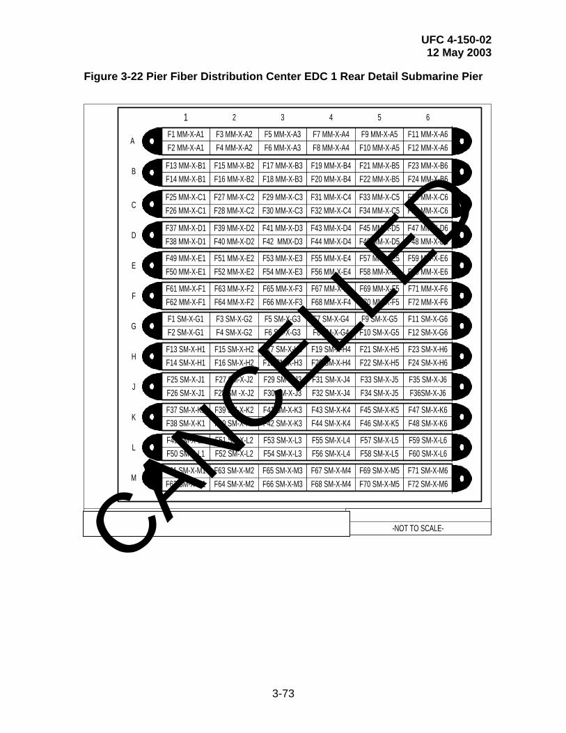
UFC 4-150-02 12 May 2003
3-73
Figure 3-22 Pier Fiber Distribution Center EDC 1 Rear Detail Submarine Pier
Figure 4: PIER FIBER DISTRIBUTION CENTER EDC 1 B-B REAR DETAIL - SUBMARINE PIERS -NOT TO SCALE-
F1 MM-X-A1F2 MM-X-A1
F3 MM-X-A2F4 MM-X-A2
F5 MM-X-A3F6 MM-X-A3
F7 MM-X-A4F8 MM-X-A4
F9 MM-X-A5F10 MM-X-A5
F11 MM-X-A6F12 MM-X-A6
F13 MM-X-B1F14 MM-X-B1
F15 MM-X-B2F16 MM-X-B2
F17 MM-X-B3F18 MM-X-B3
F19 MM-X-B4F20 MM-X-B4
F21 MM-X-B5F22 MM-X-B5
F23 MM-X-B6F24 MM-X-B6
F25 MM-X-C1F26 MM-X-C1
F27 MM-X-C2F28 MM-X-C2
F29 MM-X-C3F30 MM-X-C3
F31 MM-X-C4F32 MM-X-C4
F33 MM-X-C5F34 MM-X-C5
F35 MM-X-C6F36 MM-X-C6
F37 MM-X-D1F38 MM-X-D1
F39 MM-X-D2F40 MM-X-D2
F41 MM-X-D3F42 MMX-D3
F43 MM-X-D4F44 MM-X-D4
F45 MM-X-D5F46 MM-X-D5
F47 MM-X-D6F48 MM-X-D6
F49 MM-X-E1F50 MM-X-E1
F51 MM-X-E2F52 MM-X-E2
F53 MM-X-E3F54 MM-X-E3
F55 MM-X-E4F56 MM-X-E4
F57 MM-X-E5F58 MM-X-E5
F59 MM-X-E6F60 MM-X-E6
F61 MM-X-F1F62 MM-X-F1
F63 MM-X-F2F64 MM-X-F2
F65 MM-X-F3F66 MM-X-F3
F67 MM-X-F4F68 MM-X-F4
F69 MM-X-F5F70 MM-X-F5
F71 MM-X-F6F72 MM-X-F6
F1 SM-X-G1F2 SM-X-G1
F3 SM-X-G2F4 SM-X-G2
F5 SM-X-G3F6 SM-X-G3
F7 SM-X-G4F8 SM-X-G4
F9 SM-X-G5F10 SM-X-G5
F11 SM-X-G6F12 SM-X-G6
F13 SM-X-H1F14 SM-X-H1
F15 SM-X-H2F16 SM-X-H2
F17 SM-X-H3F18 SM-X-H3
F19 SM-X-H4F20 SM-X-H4
F21 SM-X-H5F22 SM-X-H5
F23 SM-X-H6F24 SM-X-H6
F25 SM-X-J1F26 SM-X-J1
F27 SM-X-J2F28 SM -X-J2
F29 SM-X-J3F30 SM-X-J3
F31 SM-X-J4F32 SM-X-J4
F33 SM-X-J5F34 SM-X-J5
F35 SM-X-J6F36SM-X-J6
F37 SM-X-K1F38 SM-X-K1
F39 SM-X-K2F40 SM-X-K2
F41 SM-X-K3F42 SM-X-K3
F43 SM-X-K4F44 SM-X-K4
F45 SM-X-K5F46 SM-X-K5
F47 SM-X-K6F48 SM-X-K6
F49 SM-X-L1F50 SM-X-L1
F51 SM-X-L2F52 SM-X-L2
F53 SM-X-L3F54 SM-X-L3
F55 SM-X-L4F56 SM-X-L4
F57 SM-X-L5F58 SM-X-L5
F59 SM-X-L6F60 SM-X-L6
F61 SM-X-M1F62 SM-X-M1
F63 SM-X-M2F64 SM-X-M2
F65 SM-X-M3F66 SM-X-M3
F67 SM-X-M4F68 SM-X-M4
F69 SM-X-M5F70 SM-X-M5
F71 SM-X-M6F72 SM-X-M6
1 2 3 4 5 6
A
B
C
D
E
F
G
H
J
K
L
M
CANCELLED

UFC 4-150-02 12 May 2003
3-74
Figure 3-23 Pier Fiber Distribution Center EDC 1 Front Detail Surface Pier
Figure 5: PIER FIBER DISTRIBUTION CENTER EDC 1 A-A FRONT DETAIL - SURFACE PIERS -NOT TO SCALE-
EDC-2 A6 MMEDC-2 A6 MM
EDC-2 A5 MMEDC-2 A5 MM
EDC-2 A4 MMEDC-2 A4 MM
EDC-2 A3 MMEDC-2 A3 MM
EDC-2 A2 MMEDC-2 A2 MM
EDC-2 A1MMEDC-2 A1 MM
EDC-2-B6-MMEDC-2-B6-MM
EDC-2-B5-MMEDC-2-B5-MM
EDC-2-B4-MMEDC-2-B4-MM
EDC-2-B3-MMEDC-2-B3-MM
EDC-2-B2-MMEDC-2-B2-MM
EDC-2-B1-MMEDC-2-B1-MM
EDC-2-C6-MMEDC-2-C6-MM
EDC-2-C5-MMEDC-2-C5-MM
EDC-2-C4-MMEDC-2-C4-MM
EDC-2-C3-MMEDC-2-C3-MM
EDC-2-C2-MMEDC-2-C2-MM
EDC-2-C1-MMEDC-2-C1-MM
EDC-2-D6-MMEDC-2-D6-MM
EDC-2-D5-MMEDC-2-D5-MM
EDC-2-D4-MMEDC-2-D4-MM
EDC-2-D3-MMEDC-2-D3-MM
EDC-2-D2-MMEDC-2-D2-MM
EDC-2-D1-MMEDC-2-D1-MM
BLANKBLANK
BLANKBLANK
BLANKBLANK
BLANKBLANK
BLANKBLANK
BLANK BLANK
BLANKBLANK
BLANKBLANK
BLANKBLANK
BLANKBLANK
BLANKBLANK
BLANKBLANK
BLANKBLANK
BLANKBLANK
BLANKBLANK
BLANKBLANK
BLANKBLANK
BLANKBLANK
BLANKBLANK
BLANKBLANK
BLANKBLANK
BLANKBLANK
BLANKBLANK
BLANKBLANK
6 5 4 3 2 1
A
B
C
D
E
F
G
H
J
K
L
M
EDC-2 G6 SMEDC-2 G6 SM
EDC-2 G5 SMEDC-2 G5 SM
EDC-2 G4 SMEDC-2 G4 SM
EDC-2 G3 SMEDC-2 G3 SM
EDC-2 G2 SMEDC-2 G2 SM
EDC-2 G1SMEDC-2 G1 SM
EDC-2-H6-SMEDC-2-H6-SM
EDC-2-H5-SMEDC-2-H5-SM
EDC-2-H4-SMEDC-2-H4-SM
EDC-2-H3-SMEDC-2-H3-SM
EDC-2-H2-SMEDC-2-H2-SM
EDC-2-H1-SMEDC-2-H1-SM
EDC-2-J6-SMEDC-2-J6-SM
EDC-2-J5-SMEDC-2-J5-SM
EDC-2-J4-SMEDC-2-J4-SM
EDC-2-J3-SMEDC-2-J3-SM
EDC-2-J2-SMEDC-2-J2-SM
EDC-2-J1-SMEDC-2-J1-SM
EDC-2-K6-SMEDC-2-K6-SM
EDC-2-K5-SMEDC-2-K5-SM
EDC-2-K4-SMEDC-2-K4-SM
EDC-2-K3-SMEDC-2-K3-SM
EDC-2-K2-SMEDC-2-K2-SM
EDC-2-K1-SMEDC-2-K1-SM
CANCELLED
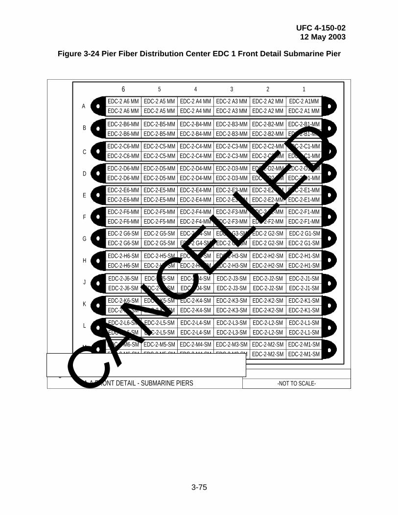
UFC 4-150-02 12 May 2003
3-75
Figure 3-24 Pier Fiber Distribution Center EDC 1 Front Detail Submarine Pier
Figure 6: PIER FIBER DISTRIBUTION CENTER EDC 1 A-A FRONT DETAIL - SUBMARINE PIERS -NOT TO SCALE-
EDC-2 A6 MMEDC-2 A6 MM
EDC-2 A5 MMEDC-2 A5 MM
EDC-2 A4 MMEDC-2 A4 MM
EDC-2 A3 MMEDC-2 A3 MM
EDC-2 A2 MMEDC-2 A2 MM
EDC-2 A1MMEDC-2 A1 MM
EDC-2-B6-MMEDC-2-B6-MM
EDC-2-B5-MMEDC-2-B5-MM
EDC-2-B4-MMEDC-2-B4-MM
EDC-2-B3-MMEDC-2-B3-MM
EDC-2-B2-MMEDC-2-B2-MM
EDC-2-B1-MMEDC-2-B1-MM
EDC-2-C6-MMEDC-2-C6-MM
EDC-2-C5-MMEDC-2-C5-MM
EDC-2-C4-MMEDC-2-C4-MM
EDC-2-C3-MMEDC-2-C3-MM
EDC-2-C2-MMEDC-2-C2-MM
EDC-2-C1-MMEDC-2-C1-MM
EDC-2-D6-MMEDC-2-D6-MM
EDC-2-D5-MMEDC-2-D5-MM
EDC-2-D4-MMEDC-2-D4-MM
EDC-2-D3-MMEDC-2-D3-MM
EDC-2-D2-MMEDC-2-D2-MM
EDC-2-D1-MMEDC-2-D1-MM
EDC-2-E6-MMEDC-2-E6-MM
EDC-2-E5-MMEDC-2-E5-MM
EDC-2-E4-MMEDC-2-E4-MM
EDC-2-E3-MMEDC-2-E3-MM
EDC-2-E2-MMEDC-2-E2-MM
EDC-2-E1-MMEDC-2-E1-MM
EDC-2-F6-MMEDC-2-F6-MM
EDC-2-F5-MMEDC-2-F5-MM
EDC-2-F4-MMEDC-2-F4-MM
EDC-2-F3-MMEDC-2-F3-MM
EDC-2-F2-MMEDC-2-F2-MM
EDC-2-F1-MMEDC-2-F1-MM
EDC-2-L6-SMEDC-2-L6-SM
EDC-2-L5-SMEDC-2-L5-SM
EDC-2-L4-SMEDC-2-L4-SM
EDC-2-L3-SMEDC-2-L3-SM
EDC-2-L2-SMEDC-2-L2-SM
EDC-2-L1-SMEDC-2-L1-SM
EDC-2-M6-SMEDC-2-M6-SM
EDC-2-M5-SMEDC-2-M5-SM
EDC-2-M4-SMEDC-2-M4-SM
EDC-2-M3-SMEDC-2-M3-SM
EDC-2-M2-SMEDC-2-M2-SM
EDC-2-M1-SMEDC-2-M1-SM
6 5 4 3 2 1
A
B
C
D
E
F
G
H
J
K
L
M
EDC-2 G6-SMEDC-2 G6-SM
EDC-2 G5-SMEDC-2 G5-SM
EDC-2 G4-SMEDC-2 G4-SM
EDC-2 G3-SMEDC-2 G3-SM
EDC-2 G2-SMEDC-2 G2-SM
EDC-2 G1-SMEDC-2 G1-SM
EDC-2-H6-SMEDC-2-H6-SM
EDC-2-H5-SMEDC-2-H5-SM
EDC-2-H4-SMEDC-2-H4-SM
EDC-2-H3-SMEDC-2-H3-SM
EDC-2-H2-SMEDC-2-H2-SM
EDC-2-H1-SMEDC-2-H1-SM
EDC-2-J6-SMEDC-2-J6-SM
EDC-2-J5-SMEDC-2-J5-SM
EDC-2-J4-SMEDC-2-J4-SM
EDC-2-J3-SMEDC-2-J3-SM
EDC-2-J2-SMEDC-2-J2-SM
EDC-2-J1-SMEDC-2-J1-SM
EDC-2-K6-SMEDC-2-K6-SM
EDC-2-K5-SMEDC-2-K5-SM
EDC-2-K4-SMEDC-2-K4-SM
EDC-2-K3-SMEDC-2-K3-SM
EDC-2-K2-SMEDC-2-K2-SM
EDC-2-K1-SMEDC-2-K1-SM
CANCELLED

UFC 4-150-02 12 May 2003
3-76
Figure 3-25 Fiber Optic Connectivity Riser Panel Detail
Figure 8: FIBER OPTIC CONNECTIVITY PIER RISER PANEL-NOT TO SCALE-
Fiber Optic UmbilicalAssembly (GFE)
Outdoor Stainless Steel Enclosure Boxwith Hinged Cover
Dim: 5'X5'X1'(Hoffman Box)
Environmental Distribution Center(EDC) Fiber Optic Patch Panel
Dim: 16.5"x14.5"x8.3"(SIECOR EDC-06P-NH)
12MM/12SM Fiber OpticCable From Pier
Fiber Distribution Center
Fiber OpticPigtail Assy\
Packard HughesP/N: 1123770H
CANCELLED
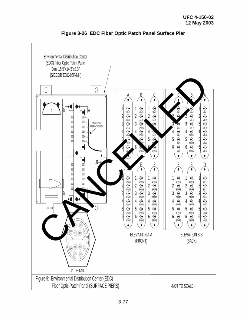
UFC 4-150-02 12 May 2003
3-77
Figure 3-26 EDC Fiber Optic Patch Panel Surface Pier
Figure 9: Environmental Distribution Center (EDC) Fiber Optic Patch Panel (SURFACE PIERS) -NOT TO SCALE-
Environmental Distribution Center(EDC) Fiber Optic Patch Panel
Dim: 16.5"x14.5"x8.3"(SIECOR EDC-06P-NH)
B
B
A
A
A B C
123456
123456
123456
1P-J1
1J-J1
2P-J1
2J-J1
3P-J1
3J-J1
4P-J1
4J-J1
SPARE
SPARE
SPARE
SPARE
5P-J1
5J-J1
6P-J1
6J-J1
SPARE
SPARE
D E F
123456
123456
123456
SPARE
SPARE
SPARE
SPARE
SPARE
SPARE
SPARE
SPARE
SPARE
SPARE
SPARE
SPARE
SPARE
SPARE
SPARE
SPARE
SPARE
SPARE
ELEVATION A-A(FRONT)
C B A
123456
123456
123456
SM-1
SM-2
SM-3
SM-4
SM-5
SM-6
MM-7
MM-8
MM-9
MM-10
MM-11
MM-12
MM-1
MM-2
MM-3
MM-4
MM-5
MM-6
F E D
123456
123456
123456
SPARE
SPARE
SPARE
SPARE
SPARE
SPARE
SPARE
SPARE
SPARE
SPARE
SPARE
SPARE
SM-7
SM-8
SM-9
SM-10
SM-11
SM-12
ELEVATION B-B(BACK)
J1
12MM/12SMFIBER OPTIC ASSY
5J
5P
6J
6P
4J
2J1J
3J
2P1P
4P3P
J1 DETAIL
CANCELLED
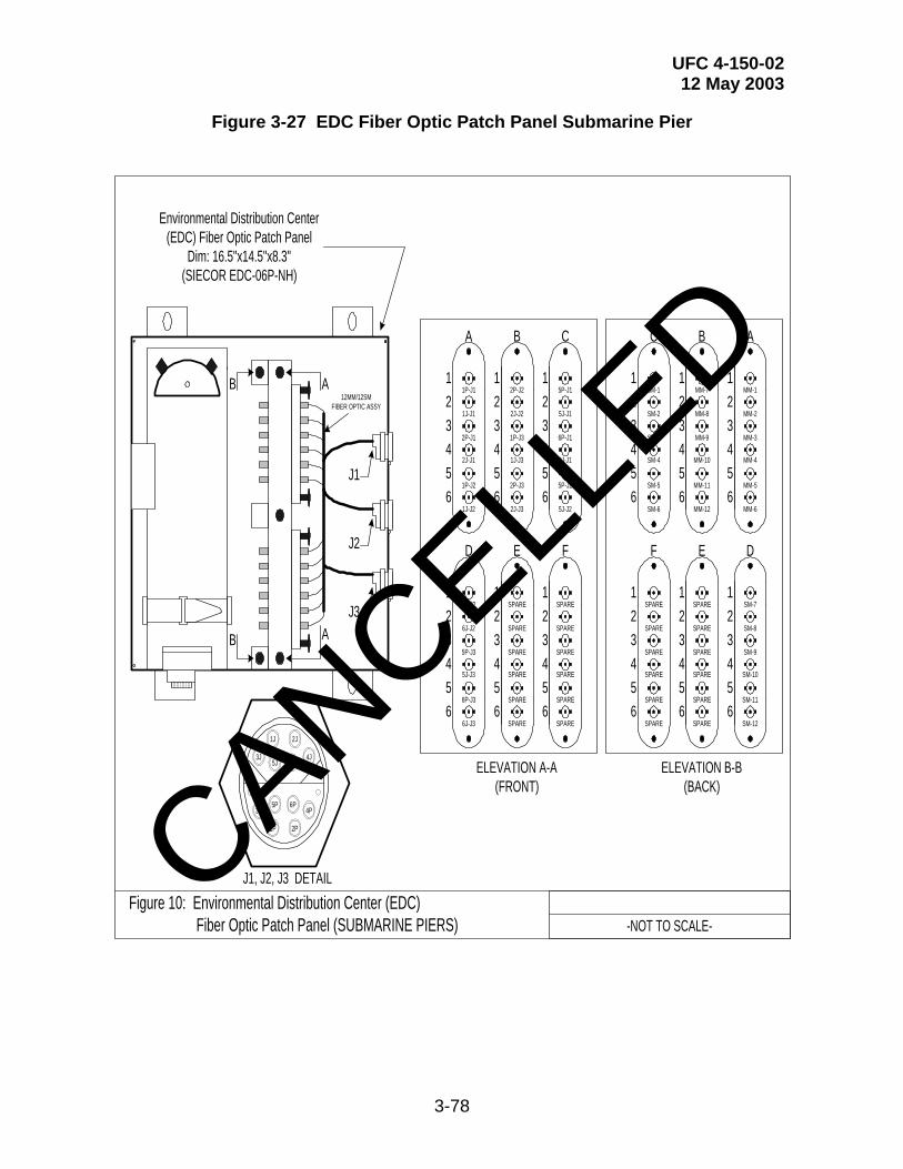
UFC 4-150-02 12 May 2003
3-78
Figure 3-27 EDC Fiber Optic Patch Panel Submarine Pier
Figure 10: Environmental Distribution Center (EDC) Fiber Optic Patch Panel (SUBMARINE PIERS) -NOT TO SCALE-
Environmental Distribution Center(EDC) Fiber Optic Patch Panel
Dim: 16.5"x14.5"x8.3"(SIECOR EDC-06P-NH)
B
B
A
A
A B C
123456
123456
123456
1P-J1
1J-J1
2P-J1
2J-J1
1P-J2
1J-J2
2P-J2
2J-J2
1P-J3
1J-J3
2P-J3
2J-J3
5P-J1
5J-J1
6P-J1
6J-J1
5P-J2
5J-J2
D E F
123456
123456
123456
6P-J2
6J-J2
5P-J3
5J-J3
6P-J3
6J-J3
SPARE
SPARE
SPARE
SPARE
SPARE
SPARE
SPARE
SPARE
SPARE
SPARE
SPARE
SPARE
ELEVATION A-A(FRONT)
C B A
123456
123456
123456
SM-1
SM-2
SM-3
SM-4
SM-5
SM-6
MM-7
MM-8
MM-9
MM-10
MM-11
MM-12
MM-1
MM-2
MM-3
MM-4
MM-5
MM-6
F E D
123456
123456
123456
SPARE
SPARE
SPARE
SPARE
SPARE
SPARE
SPARE
SPARE
SPARE
SPARE
SPARE
SPARE
SM-7
SM-8
SM-9
SM-10
SM-11
SM-12
ELEVATION B-B(BACK)
J2
12MM/12SMFIBER OPTIC ASSY
5J
5P
6J
6P
4J
2J1J
3J
2P1P
4P3P
J1, J2, J3 DETAIL
J1
J3
CANCELLED

UFC 4-150-02 12 May 2003
3-79
Figure 3-28 Rubber Gasket Cutout Surface Pier
Figure 11: HOFFMAN ENCLOSURE LAYOUT (SURFACE PIERS)-NOT TO SCALE-
TO S
HIP
/BO
AT
TO PIER FDC
3"
Rubber Gasket
FRONT VIEW SIDE VIEW
CANCELLED
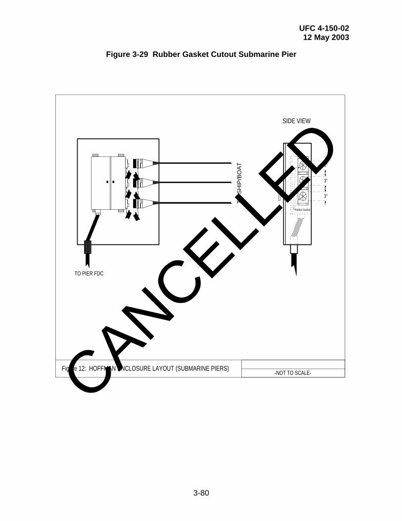
UFC 4-150-02 12 May 2003
3-80
Figure 3-29 Rubber Gasket Cutout Submarine Pier
Figure 12: HOFFMAN ENCLOSURE LAYOUT (SUBMARINE PIERS)-NOT TO SCALE-
TO S
HIP
/BO
AT
TO PIER FDC
3"
Rubber Gasket
SIDE VIEW
3"
3"
CANCELLED
UFC 4-150-02 12 May 2003
4-1
CHAPTER 4
SUPPLY AND AMMUNITION PIERS
4-1 STEAM AND COMPRESSED AIR. In general, steam and compressed air services are not required on supply and ammunition piers. However, ammunition piers that serve ballistic submarines require special considerations. See paragraph 4-7.
4-2 SALTWATER AND NONPOTABLE WATER. Provide fire protection water as required for active berthing facilities. However, consult with the Activity and the cognizant NAVFAC EFD/EFA OR USACE DISTRICT regarding ammunition piers that are in an isolated area and are far removed from mobile fire apparatus. For remote ammunition piers, design a pumping station to supply between 9,463 and 13,248 lpm (2500 and 3500 gpm) at sufficient pressure to provide 517 kPa (75 psig) residual pressure at the most remote outlet. Outlet connection threads must be national standard male hose threads unless required otherwise to serve an existing system.
4-3 POTABLE WATER, SEWER, AND OILY WASTE. For supply piers, requirements are the same as those for active berthing facilities. For ammunition piers, provide potable water only when indicated in the project directive. However, oily waste and sewer collection systems should always be provided. For all three systems, see the requirements defined in Chapter 3.
4-4 ELECTRICAL SERVICE. Shore power for ships hotel service, lighting, and power for industrial services (as required) will be provided on ammunition piers and wharves that load missiles for nuclear powered vessels. This provision lengthens the life of vessel reactors and decreases manpower requirements during the loading / unloading operation. Electrical systems provided on ammunition piers must be designed for the hazardous rating actually encountered and in accordance with NFPA 70.
4-5 TELECOMMUNICATION SYSTEMS. Both supply piers and ammunition piers require telecommunication systems. However, full services that are defined for active and repair berths are not required except for ammunition piers that serve ballistic submarines. Consult with the Activity and the cognizant NAVFAC EFD/EFA OR USACE DISTRICT for specific requirements. In general, the design guides for active and repair berths are applicable. The systems required are to be evaluated on a project-by-project basis. Lastly, comply with all hazardous requirements associated with ammunition piers. CANCELL
ED
UFC 4-150-02 12 May 2003
5-1
CHAPTER 5
FUELING PIERS
5-1 STEAM AND COMPRESSED AIR. In general, steam and compressed air services are not required on fueling piers.
5-2 SALTWATER AND NONPOTABLE WATER. Ships loading or unloading POL products at fueling piers will never be cold iron and will therefore not require a shore-to-ship fire protection water connection.
5-3 POTABLE WATER, SEWER, AND OILY WASTE. Supply potable water systems at locations where connections may be made to existing systems. Maximum potable water requirements are 3,785 lpm (1,000 gpm) with 276 kPa (40 psi) residual pressure at the most remote outlet. Design outlets as for active berthing and space about 61 m (200 ft) apart. Provide oily waste and sewage collection systems at all fueling piers unless instructed otherwise. Consult with the Activity and the cognizant NAVFAC EFD/EFA OR USACE DISTRICT. Provide all three systems in accordance with the criteria defined in Chapter 3.
5-4 POL SYSTEMS. Refer to MIL-HDBK-1022A for information on piping and other appurtenances, including manifolds, hoses and shelters, connections and adapters, hose handling equipment, bilge and ballast lines, stripper pumps, environmental protection, and other equipment. In general, ships use a 152.3 mm (6-in) commercial flanged connection. Verify before commencing design of shore connections.
5-5 ELECTRICAL SERVICE. Ships service, temporary lighting, and ships industrial power are not required for fueling piers and quaywalls. Consult with the Activity and the cognizant NAVFAC EFD/EFA OR USACE DISTRICT regarding electrical systems that directly serve the pier. Evaluate all hazardous requirements and preferences that may be encountered.
5-6 TELECOMMUNICATION SYSTEMS. Fueling piers require telecommunication systems. However, full services that are defined for active and repair berths are not required. Consult with the Activity and the cognizant NAVFAC EFD/EFA OR USACE DISTRICT for specific requirements. In general, the design guides for active and repair berths are applicable. The systems required are to be evaluated on a project-by-project basis. Lastly, comply with all hazardous requirements associated with fueling piers.
5-7 ADDITIONAL REQUIREMENTS. Refer to MIL-HDBK-1022A for additional requirements.
5-8 FIRE PROTECTION. Refer to UFC 3-600-01, Design: Fire Protection Engineering For Facilities. Consult with the Fire Protection Engineering Departments, both at the local level and at the NAVFAC EFD/EFA OR USACE DISTRICT level.
CANCELLED

UFC 4-150-02 12 May 2003
6-1
CHAPTER 6
MISCELLANEOUS PROVISIONS
6-1 FREEZE PROTECTION
6-1.1 Where Required. Provide freeze protection for saltwater, fresh-water, sanitary-waste (sewage), and oily-waste (bilge) pipes exposed on piers and wharves and in drydocks when located in freezing climates.
6-1.2 Regional Weather Differences. See Figure C-1 and Table C-1. For design purposes, coastlines within the United States can be divided into the five regions listed below. Table C-1 lists average historical weather data for the five regions. For freeze protection systems at locations outside of the United States, match weather data (insofar as possible) to one of the regions in Table C-1 and design accordingly. The five weather regions are defined as follows:
Region I: "Severe": Alaska, Maine, New Hampshire, Great Lakes and inland locations.
Region II: "Cold": Connecticut, Massachusetts, Rhode Island, and New York.
Region III: "Moderate": Pennsylvania, New Jersey, Delaware, Maryland, and Washington, DC.
Region IV: "Mild": Washington, Oregon, Virginia, and North Carolina.
Region V: "Very Mild": California, South Carolina, Georgia, Texas, Mississippi, Louisiana, Alabama, and Florida.
6-1.3 Methods. The methods described below vary with climate. Use the methods recommended below when the relative costs of electricity, sewage disposal, and freshwater are not abnormally high. Where the cost of electricity, sewage disposal, or water is abnormally high, then modify the freeze protection system and use an approved method that minimizes operating cost. Use approved life cycle cost procedures and submit analysis.
6-1.4 Protection in Regions I and II
6-1.4.1 Water Lines. For water lines, provide freeze protection by using a combination of electric heat tape and pipe insulation. The suggested combinations of insulation thickness and heating (watt density) for various pipe sizes are shown in Table C-2. Heat tape should be controlled by remote thermostats having sensors taped to the surface of pipes and under the insulation. Consult with the Activity and the cognizant NAVFAC EFD/EFA OR USACE DISTRICT regarding preferred heat tape systems and methods. Several sections of heat tape may be required due to overall pipe length. Provide each section of heat tape with a dedicated thermostat. Thermostats must be in a protected location that is also accessible. The heating requirement given in Table C-2
CANCELLED

UFC 4-150-02 12 May 2003
6-2
(6 watts/foot) is the watt density available for a typical electric heat tape. Any watt density from 4 to 10 watts/foot would be suitable, but insulation thicknesses must be adjusted to compensate. Insulation thicknesses given in Table C-2 are based upon polyurethane. Adjust thickness for other insulation materials as based upon their rated thermal conductivity values. Protect backflow devices, valves, and risers with electric heat tape and preformed polyurethane insulation kits. Heat tape systems must be maintainable to be successfully used for the system's expected life span. To improve maintainability, use multiple sections of heat tape instead of extended single circuits. The designer may need to consider special heating systems in which heating elements are placed in channels alongside the pipe. These systems periodically terminate in accessible junction boxes. Maintenance personnel can then easily replace an inoperable section. It is also much easier to troubleshoot when the heating system is divided into reasonable segments with accessible test points.
6-1.4.2 Sewer and Oily Waste Lines. A combination of electric heat tape and pipe insulation should be used in accordance with Table C-2 for: (1) exposed gravity sewer piping which drains fixtures directly; (2) exposed oily waste piping; and (3) for those portions of exposed pressure lines (sewage and oily waste) which will not completely drain upon cessation of pumping. Heat tape may not be required (insulation only) for exposed pressure and gravity sewer and oily waste piping (or portions thereof) which receive material intermittently and which drain well when pumping stops. Neither heat tape nor insulation may be required for pipe risers and valves above pier decks and in drydock galleries.
6-1.5 Protection in Regions III and IV
6-1.5.1 Fresh Water Lines. For water lines, the preferred method of freeze protection in these regions is to use a combination of insulation and a flushing of water through the pipes. Insulation thickness for various pipe sizes, and pipe sizes for which flushing is necessary, are defined in Appendix C Table C-3. Insulation thicknesses are such that for expected durations of subfreezing temperatures less than 50 percent of pipe contents will freeze. Where flushing is indicated, use thermostatically actuated solenoid valves. Size each valve for a rate at which the entire contents of exposed piping can bleed in 8 to 12 hours. Thermostats should be in protected locations and sensors are to be taped to the surface of pipes and under the insulation. Thermostats should be factory set to open the flushing valves at -1.1 degrees C (30 degrees F) and to close the valves at approximately 2 degrees C (35 degrees F). Flushing valves (freeze protection valve) and associated thermostats should be located at each ship's connection and at any other line extremity to protect the most remote valve component in the system. Insulation thicknesses given in Table C-3 are based upon polyurethane. Adjust thickness for other insulation materials as based upon their rated thermal conductivity values. Insulation must also be applied to backflow devices and valves. Special care must be taken to prevent the freezing of flushing valves and associated pipe connections. If water is scarce, or if the winter temperature of buried water mains is below 7.2 degrees C (45 degrees F), heat tape should be used in lieu of flushing. In this event, the design should be based upon the data defined in Table C-4.
CANCELLED

UFC 4-150-02 12 May 2003
6-3
6-1.5.2 Sewer and Oily Waste Lines. A combination of electric heat tape and pipe insulation should be used in accordance with Table C-4 for: (1) exposed gravity sewer piping which drains fixtures directly; (2) exposed oily waste piping; and (3) those portions of exposed pressure lines (sewage and oily waste) which will not drain completely upon cessation of pumping. Neither insulation nor heating is required for exposed sewer and oily waste piping (or portions thereof) which receive material intermittently and which drain well when pumping stops. This applies to both pressure lines and gravity lines.
6-1.6 Protection in Region V. In portions of region V in which the temperature can drop below -4 degrees C (25 degrees F), use a properly sized flushing valve, atmospheric thermostat, and timer to bleed approximately 132.5 l (35 gallons) per inch of pipe diameter for each 30.5 m (100 ft) of fresh water pipe. This flushing is to be applied over an 8 to 12 hour period on each day that the ambient temperature drops below –4 oC (25 oF). Pipes need not be insulated, but flushing valves and connections must be located at system extremities and must be protected from freezing.
6-1.7 Modification of Requirements for Saltwater. Because seawater freezes at a temperature approximately -15.3 oC (4.5 oF) lower than that at which freshwater freezes, make the following adjustments when designing freeze protection for exposed saltwater mains:
• In regions I and II, treat saltwater the same as required for freshwater.
• In region III, design as for region IV.
• In region IV, design as for region V.
• In region V, no freeze protection is necessary for saltwater at any location.
6-1.8 Materials
6-1.8.1 Pipe. Piping materials must be metallic where heat tape is required. Where a flushing system is utilized, any approved piping material may be used.
6-1.8.2 Heat Tape. Flat style electric heat tape is recommended. Heat tape should be easy to splice and repair and must be waterproof. A low watt density (4 to 10 watts per lineal foot of pipe) is recommended, and the ability to lap the tape without damage should be required. When heat tape is used with the insulation thicknesses listed in Tables C-2 and C-4, they will cycle 30 to 60 percent of the time on the coldest days.
6-1.8.3 Insulation and Covering. Closed-cell foam-type insulations (such as cellular glass) having low moisture absorption qualities should be used for Regions I and II due to the destructive effect of freezing on wet insulations. Use closed-cell foam-type insulation for regions III and IV if wave action and/or immersion are possible. Cover all insulation with a watertight metallic or plastic system.
CANCELLED

UFC 4-150-02 12 May 2003
6-4
6-1.8.4 Valves and Thermostats. Select single-seated solenoid valve shaving flow constants suitable for bleeding proper quantities of water in the prescribed interval. Temperature sensors should be atmospheric or surface type and sense water temperature not ambient air temperature. Thermostats may be bimetallic, thermistor, or resistance (RTD) type, having differentials of -16.6 oC (2 oF) to -15 oC (5 oF).
6-2 PIPING IDENTIFICATION
6-2.1 Primary Identification. Identify each valve on a pier, wharf, or drydock by a plain language brass tag, and labeled. (Example: "potable water" or "sewer".) Additionally, at each shore-to-ship utility connection, name plates or stenciled letters near the connection must identify the utility in plain language.
6-2.2 Color Coding. Two sources of design requirements govern color-coding for pier, wharf, and drydock piping.
6-2.2.1 Distribution Piping On or Under Deck and Ashore. Such piping, exclusive of shore-to-ship utility connections, must be color coded in accordance with MIL-STD-101, “Color Code for Pipelines and for Compressed Gas Cylinders”. Applicable requirements must be specified in the design documents.
6-2.2.2 Shore-to-Ship Utility Connections. Such piping (including valves, operating levers, ends of hose assemblies, risers, and adjacent piping) must be specified to be color-coded in accordance with Table 6-1. Color-coding may also extend to adjacent curbs, protective rails, posts, and walls.
6-3 OPERATIONAL NOTICES. Provide the following operational notices. Consult with the Activity and the cognizant NAVFAC EFD/EFA OR USACE DISTRICT regarding other desired notices, nameplates, warning signs, and so forth.
• Bleed systems must be marked with the following warning:
”Freeze protection valve. Water will flow below 35 degrees F. Do not close.”
• Heat tape systems must be marked with the following warning:
“Heat tape system (self limiting). Do not disconnect power.” CANCELL
ED
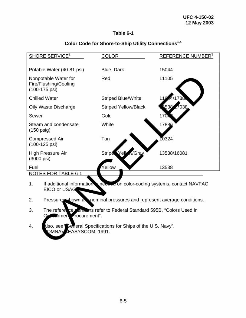
UFC 4-150-02 12 May 2003
6-5
Table 6-1
Color Code for Shore-to-Ship Utility Connections1,4
SHORE SERVICE2 COLOR REFERENCE NUMBER3
Potable Water (40-81 psi) Blue, Dark 15044
Nonpotable Water for Red 11105 Fire/Flushing/Cooling (100-175 psi)
Chilled Water Striped Blue/White 11044/17886
Oily Waste Discharge Striped Yellow/Black 13538/17038
Sewer Gold 17043
Steam and condensate White 17886 (150 psig)
Compressed Air Tan 10324 (100-125 psi)
High Pressure Air Striped Yellow/Gray 13538/16081 (3000 psi)
Fuel Yellow 13538 NOTES FOR TABLE 6-1
1. If additional information is needed on color-coding systems, contact NAVFAC EICO or USACE.
2. Pressures shown are nominal pressures and represent average conditions.
3. The reference numbers refer to Federal Standard 595B, “Colors Used in Government Procurement”.
4. Also, see “General Specifications for Ships of the U.S. Navy”, COMNAVSEASYSCOM, 1991.
CANCELLED

UFC 4-150-02 12 May 2003
7-1
CHAPTER 7
U.S. ARMY REQUIREMENTS
7-1 APPLICABILITY. This chapter is applicable for waterfront facilities designed for U.S. Army vessels.
7-2 POTABLE WATER. Provide potable water in sufficient capacity to permit the filing of a vessel’s tank in such time as to avoid delays in the operation of the vessel.
7-2.1 Quantity and Pressure Requirement. Provide a minimum flow of 6.3 l/s (100 gpm) with a minimum residual pressure of 173 kPa (25 psi) at the most remote outlet.
7-2.2 Piping and Outlets. Install one 63.5 mm (2-1/2 in) connection at each service outlet. Potable water outlets on piers and wharves should have a reduced pressure-type backflow prevention device. The piping must be insulated and provided with electrical heat tape if the lines are normally full of water and subject to freezing temperatures. Where thermal expansion is a problem, provision should be made for expansion joints or loops. Figure 7-1 shows a typical potable water connection in the pier deck.
7-3 ELECTRIC POWER
7-3.1 Electrical System Characteristics. The main electrical system providing power to ships will be nominal 480-volts, three-phase, 60-Hz, supplied from substations preferably located on the piers. For lighting service, a 120-volt, 60-cycle, single-phase power may be provided.
7-3.2 Ground System. At piers, wharves, and other waterfront structures, a ground system that will measure not more than 3 ohms must be provided for permanent electrical equipment.
7-4 LOCATION AND NUMBERS OF SERVICE POINTS. A minimum of two service points will be provided for each berth and located for the convenience of the using vessels. Each service point must supply electric power and water service as outlined above. Depending upon the physical site conditions of each specific installation, the point of connection for each service may be located in a single service box, or may be placed in separate but closely grouped boxes. Boxes should be located as close as practicable to the berthing face of the structure so that connected hoses and electric cables are not subject to vehicular traffic damage.
CANCELLED
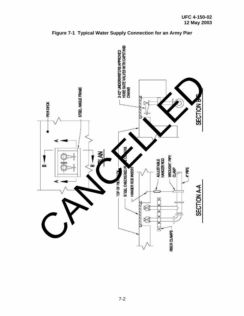
UFC 4-150-02 12 May 2003
7-2
Figure 7-1 Typical Water Supply Connection for an Army Pier
CANCELLED
UFC 4-150-02 12 May 2003
7-3
7-5 MISCELLANEOUS
7-5.1 Telephone Service. Provide telephone service and outlet connectors for each berth. Locate for the convenience of the using vessels.
7-5.2 Lighting. Satisfactory illumination should be ensured for night operations. For open watering areas on the pier where ship loading or unloading occurs, a lighting intensity of at least 54 lux (5 footcandles) should be maintained. The illumination level of 54 lux (5 footcandles) should also be provided for areas of warehouses or storage buildings.
7-5.3 Fire Protection. Refer to UFC 3-600-01, Design: Fire Protection Engineering For Facilities.
7-5.4 Sanitary Facilities and Sewage Disposal. A dockside connection to a sewage disposal system must be provided for the disposal of sewage and oily wastes from vessels.
CANCELLED

UFC 4-150-02 12 May 2003
A-1
APPENDIX A
REFERENCES
GOVERNMENT PUBLICATIONS 1. Unified Facilities Criteria http://65.204.17.188//report/doc_ufc.html
UFC 3-600-01, Design: Fire Protection Engineering for Facilities UFC 4-15010-01, General Criteria for Waterfront Construction UFC 4-21310-01, Graving Drydocks
2. Unified Facilities Guide Specifications www.ccb.org
UFGS 02531, Sanitary Sewers UFGS 13110N, Cathodic Protection by Galvanic Anodes UFGS 13111N, Cathodic Protection by Impressed Current UFGS 13112N, Cathodic Protection System (Steel Water Tanks) UFGS 16145N, 480 Volt Pier Power Outlet Assemblies UFGS 16341N, Insulated Pad-Mounted Switchgear UFGS 16360N, Secondary Unit Substations UFGS 16442N, Switchboards and Switchgear
3. Defense Standardization Program (DSP) http://astimage.daps.dla.mil/online/new/
MIL-DTL-915/6K, Cable Power, Electrical, 600-Volts, for Outboard Use Only MIL-C-24368/1B, Connector Assemblies, Plugs and Receptacles, Electric Power Transfer, Shore-to-Ship and Ship-to-Ship, MIL-C-52404B(1), Connection Hose,
CANCELLED

UFC 4-150-02 12 May 2003
A-2
Fire and Water MIL-S-12165F, Strainer Suction, Fire house, and Strainer Suction, Hose. FED-STD-595B, Colors Used in Government Procurement MIL-STD-101, Color Code for Pipelines and for Compressed Gas Cylinders CID A-A-59326, Coupling Halves, Quick-Disconnect, Cam-Locking Type MIL-HDBK-1003/5, Compressed Air and Vacuum Systems (Inactive for New Design) MIL-HDBK-1003/8, Exterior Distribution of Steam, Water, High Temperature Water, Chilled Water, Natural Gas, and Compressed Air MIL-HDBK-1004/1, Electrical Engineering, Preliminary Design Considerations MIL-HDBK-1004/4, Electrical Utilization Systems MIL-HDBK-1004/6, Electrical Engineering, Lightning Protection Systems MIL-HDBK-1004/10, Electrical Engineering, Cathodic Protection MIL-HDBK-1005/7A, Water Supply Systems MIL-HDBK-1005/9, Industrial and Oily Wastewater Control MIL-HDBK-1007/3A, Soil Dynamics and Special Design Aspects
CANCELLED

UFC 4-150-02 12 May 2003
A-3
MIL-HDBK-1022A, Petroleum Fuel Facilities MIL-HDBK-1025/1, Piers and Wharves MIL-HDBK-1025/10, Safety of Electrical Transmission and Distribution Systems MIL-HDBK-1110, Paints and Protective Coatings for Facilities
4. Naval Facilities Engineering Command (NAVFACENGCOM) Engineering Innovation and Criteria Office 1510 Gilbert Street Norfolk VA 23511-2669 http://criteria.navfac.navy.mil
P-89, Engineering Weather Data P-442, Economic Analysis Handbook MO-340, Ship-to-Shore Hose Handling Operations
5. Naval Facilities Engineering Service Center (NFESC) 1100 23rd Avenue Port Hueneme, CA 93043-4370 www.nfesc.navy.mil
TDS-2025-SHR, Polymer Composite Utility Pipe Hangers TN-1586, Steam Separator Test and Evaluation Bilge and Oily Wastewater Treatment System
6. Code of Federal Regulations http://www.access.gpo.gov/nara/cfr/
29 CFR 1910, Occupational Safety and Health Administration, Department of Labor
Occupational Safety and Health Standards
40 CFR 141, U.S. Environmental Protection Agency:
National Primary Drinking Water Regulations National Secondary Drinking Water Regulations
40 CFR 1700, U.S. Environmental Protection Agency, Department of Defense:
CANCELLED
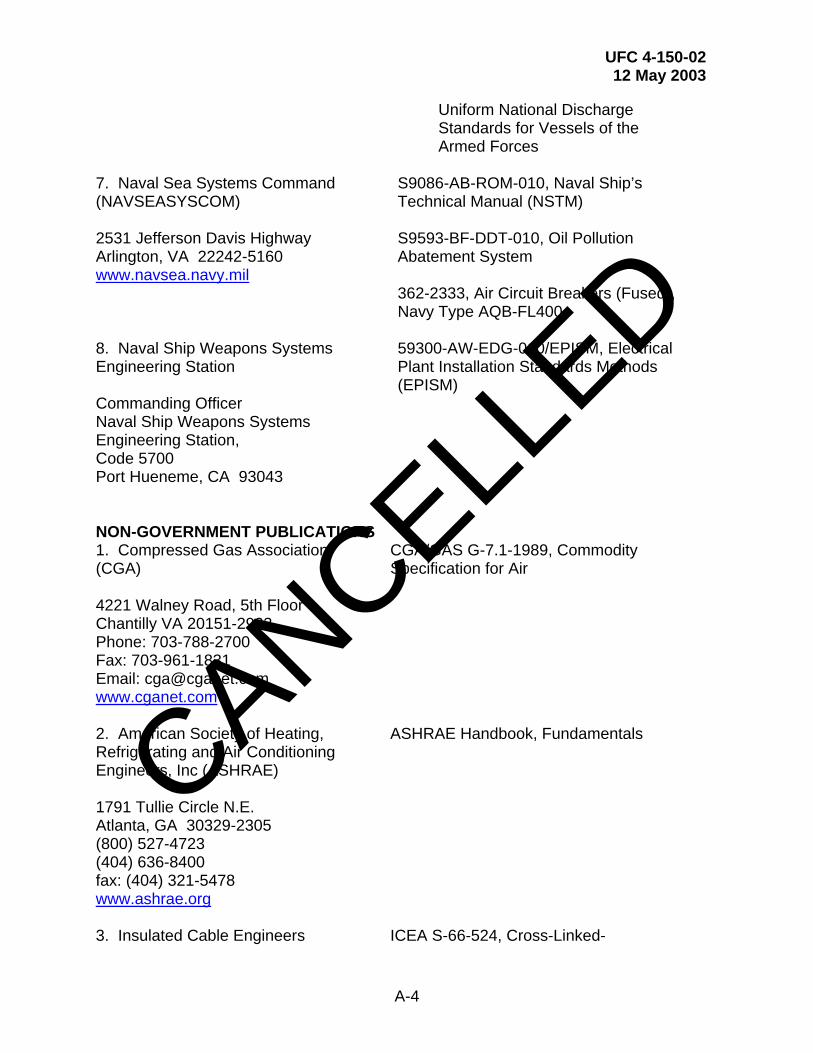
UFC 4-150-02 12 May 2003
A-4
Uniform National Discharge Standards for Vessels of the Armed Forces
7. Naval Sea Systems Command (NAVSEASYSCOM) 2531 Jefferson Davis Highway Arlington, VA 22242-5160 www.navsea.navy.mil
S9086-AB-ROM-010, Naval Ship’s Technical Manual (NSTM) S9593-BF-DDT-010, Oil Pollution Abatement System 362-2333, Air Circuit Breakers (Fused), Navy Type AQB-FL400
8. Naval Ship Weapons Systems Engineering Station Commanding Officer Naval Ship Weapons Systems Engineering Station, Code 5700 Port Hueneme, CA 93043
59300-AW-EDG-010/EPISM, Electrical Plant Installation Standards Methods (EPISM)
NON-GOVERNMENT PUBLICATIONS 1. Compressed Gas Association (CGA) 4221 Walney Road, 5th Floor Chantilly VA 20151-2923 Phone: 703-788-2700 Fax: 703-961-1831 Email: [email protected] www.cganet.com
CGA/GAS G-7.1-1989, Commodity Specification for Air
2. American Society of Heating, Refrigerating and Air Conditioning Engineers, Inc (ASHRAE) 1791 Tullie Circle N.E. Atlanta, GA 30329-2305 (800) 527-4723 (404) 636-8400 fax: (404) 321-5478 www.ashrae.org
ASHRAE Handbook, Fundamentals
3. Insulated Cable Engineers ICEA S-66-524, Cross-Linked-
CANCELLED

UFC 4-150-02 12 May 2003
A-5
Association (ICEA) Box 1568 Carrollton, GA 30112 www.icea.net
Thermosetting Polyethylene Insulated Wire and Cable for Transmissions and Distribution of Electrical Energy
4. NACE International 1440 S. Creek Drive, Houston, TX 77048-4906 (281) 228-2600 fax: (281) 228-6300 http://nace.org/nace/index.asp
NACE Standard RP01-69, Control of External Corrosion of Underground or Submerged Metallic Piping Systems NACE Standard RP02-85, Control of External Corrosion on Metallic Buried, or Partially Buried, or Submerged Liquid Storage
5. National Fire Protection Association (NFPA) 1 Batterymarch Park P.O. Box 9101 Quincy, MA 02269-9101 (617) 770-3000 fax: (617) 770-0700 www.nfpa.org
NFPA 20, Centrifugal Fire Pumps NFPA 70, National Electrical Code NFPA 780, Standard for the Installation of Lightning Protection Systems
6. Society for Protective Coatings (SSPC) 40 24th Street, 6 Floor Pittsburgh, PA 15222-4656 (877) 281-7772 www.sspc.org
Volume 2, Painting Manual, Systems and Specifications (Includes color identification index system)
7. Water Environment Federation (WEF) 601 Wythe Street, Alexandria VA, 22314-1994 (800) 666-0206 fax: (703) 684-2492 www.wef.org
MOP FD-5, Gravity Sanitary Sewer Design and Construction
8. National Electrical Manufacturer’s Association (NEMA) 1300 N. 17th Street, Suite 1847,
NEMA C57.12.29, Pad-Mounted Equipment – Enclosure Integrity for Coastal Environments
CANCELLED
UFC 4-150-02 12 May 2003
A-6
Rosslyn, VA, 22209 (703) 841-3200 fax: (703) 841-5900 e-mail: [email protected]. www.nema.org
NEMA C84.1, Electric Power Systems and Equipment – Voltage Ratings (60 Hz)
9. ASTM International 100 Barr Harbor Drive West Conshohocken, PA 19428-2959 (610) 832-9585 fax: (610) 832-9555 www.astm.org
Metals and Alloys in the Unified Numbering System, January 2001 A 276, Standard Specification for Stainless Steel Bars and Shapes B 148, Standard Specification for Aluminum-Bronze Sand Castings B 164, Standard Specification for Nickel-Copper Alloy Rod, Bar and Wire B165, Standard Specification for Nickel-Copper Alloy (UNS N04400) Seamless pipe and Tube
CANCELLED
UFC 4-150-02 12 May 2003
B-1
APPENDIX B
GLOSSARY
Active Berthing. A pier or wharf with berths used for homeport or light repair purposes, usually with a full or partial crew aboard, and always with ships in active status.
Activity. The organization (or organizations) that is responsible for the daily and routine operation and maintenance of the associated waterfront facility.
APTS. Activity providing telephone service. The organization responsible for the daily and routine operation and maintenance of the waterfront's telecommunication system (or systems).
Berth. A specific, marked-off length, along a pier or wharf, containing ships services appropriate for the ship classes which may be assigned to it.
Berthing Pier. A general term for a pier with berths and ships services.
Berthing Plan. A plan devised by each facility showing all berthing areas with ships assignments. May be permanent or temporary, depending upon the type of facility.
Bollard. A single-post fitting to which mooring lines from vessels are attached.
Capstan. A motorized, vertical-drum device used to tension lines for positioning ships, usually in drydock.
Cleat. A mooring fitting having two diverging horizontal arms to which mooring lines from vessels are attached.
Cold Iron. Used to describe the condition of a ship when all shipboard boilers, engines, and generators are inoperative during repairs and can furnish none of the required ships services.
Cooling/Flushing Water. Water (usually nonpotable or salt) supplied to ships for condenser-cooling, fixture-flushing and other miscellaneous uses.
Dedicated Berth. A berth having required services for, and dedicated to use by, a specific ship for an extended period of time.
NAVFAC EFD/EFA. Engineering field division/engineering field activity. The geographical representative of the Naval Facilities Engineering Command (NAVFAC) responsible for the implementation of Navy policies, guidance and instructions.
Graving Drydock. A permanent concrete drydocking structure requiring the use of caisson and dewatering pumps.
CANCELLED

UFC 4-150-02 12 May 2003
B-2
Hotel Services. Dockside utilities provided for a ship at berth (also called ships services, utility services, and cold iron services).
Inactive Berthing. Permanent or semi-permanent berthing areas for ships out of service, with crew normally not aboard.
Nested Ships. Two or more ships berthed side by side, with utility services supplied from berth side to the outer ships via ships header systems or hoses and cables strung across decks.
Oily Waste. Water (usually salt) from ships bilge which has been contaminated with petroleum products (fuel or lube oils) and which cannot discharge either to surface waters or to sanitary sewer.
Overhaul Facility. Generally used interchangeably with Repair Facility.
Pier. A dock, built from the shore out into the harbor, which is used for berthing and mooring vessels.
POL. Petroleum, oil and lubricants. An acronym used to describe petroleum products, and the facilities used in their storage and handling. As used herein, applies to marine fuels, jet fuels and lubricants.
Quaywall. A heavy gravity or platform structure fronting on navigable water, behind which earth fill is placed to a level grade along its length.
Repair Facility. Locations where ship repair activities take place, such as at a shipyard or ship-repair facility. Facilities may utilize repair piers, drydocks, or both. (Also, Overhaul Facility.)
Telecommunications. Systems of communicating speech or impulses via wire or cable over distances, such as telephone, data transmission, coded transmission, cable TV and signal or alarm circuits.
USACE DISTRICT. The geographical representative of the U.S. Army Corps of Engineers (USACE) responsible for the implementation of Army policies, guidance and instructions.
Wharf. A dock, oriented approximately parallel to shore, with more than one access connection with the shore; a wharf is used for berthing or mooring vessels. May also be as above, except with continuous connection to shore.CANCELL
ED

UFC 4-150-02 12 May 2003
C-1
APPENDIX C
CLIMATOLOGICAL DATA
Figure Title Page
C-1 U.S. Winter Weather Severity By Region.............................................C-2
Table Title Page
C-1 Regional Weather Data........................................................................C-3
C-2 Freeze Protection By Insulation And Heating:
Suggested Combinations For Regions I and II ....................................C-3
C-3 Freeze Protection By Insulation And Flushing:
Suggested Combinations For Regions III and IV .................................C-4
C-4 Freeze Protection By Insulation And Heating:
Suggested Combinations For Regions III and IV .................................C-4
CANCELLED

UFC 4-150-02 12 May 2003
C-2
Figure C-1 U.S. Winter Weather Severity by Region
CANCELLED

UFC 4-150-02 12 May 2003
C-3
Table C-1 Regional Weather Data
AVERAGE EXTREME MEDIAN AVERAGE OF 97 1/2%
JANUARY MINIMUM ANNUAL 97 1/2% TEMP AND EXTREME
Temp Temp EXTREMES Temp MINIMUM
REGION (deg F) (deg F) (deg F) (deg F) (deg F) DAYS
I 24 -30 -11 0 -15 1275
II 29 -14 1 10 -2 1125
III 34.5 1 7 15 8 950
IV 34.5 3 16 24 13 750
V 50.5 17 21 32 24 450
Table C-2 Freeze Protection by Insulation and Heating: Suggested Combinations for Regions I and II
REGION I REGION II
PIPE INSULATION INSULATION SIZE THICKNESS HEATING THICKNESS HEATING (inch) (inch) (watts/foot) (inch) (watts/foot)
2 1/2 6 1/2 6
3 1/2 6 1/2 6
4 1 6 1 6
6 1 6 1 6
8 1-1/2 6 1-1/2 6
10 1-1/2 6 1-1/2 6
12 1-1/2 6 1-1/2 6 CANCELL
ED

UFC 4-150-02 12 May 2003
C-4
Table C-3 Freeze Protection by Insulation and Flushing: Suggested Combinations for Regions III and IV
REGION III REGION IV
PIPE INSULATION INSULATION SIZE THICKNESS FLUSHING THICKNESS FLUSHING (inch) (inch) FEATURE (inch) FEATURE
2 1 Yes 1 Yes
3 1 Yes 1 Yes
4 1 Yes 1 Yes
6 1 Yes 1 Yes
8 1 No 1 No
10 1 No 1 No
12 1 No 1 No
Table C-4 Freeze Protection by Insulation and Heating: Suggested Combinations for Regions III and IV
REGION III REGION IV
PIPE INSULATION INSULATION SIZE THICKNESS HEATING THICKNESS HEATING (inch) (inch) (watts/foot) (inch) (watts/foot)
2 1/2 6 1/2 6
3 1/2 6 1/2 6
4 1/2 6 1/2 6
6 1/2 6 1/2 None
8 1 None 1 None
10 1 None 1 None
12 1 None 1 None
CANCELLED

UFC 4-150-02 12 May 2003
D-1
APPENDIX D
TYPICAL ELECTRICAL DIAGRAMS AND DETAILS
Figure Title Page
D-1 Electrical System For A Double-Deck Pier D-2
D-2 Pier Electrical Distribution D-11
D-3 Portable Substation D-16
D-4 Ship Service Outlet Assembly D-19
D-5 Pier Electrical Distribution For Temporary Services D-21
CANCELLED
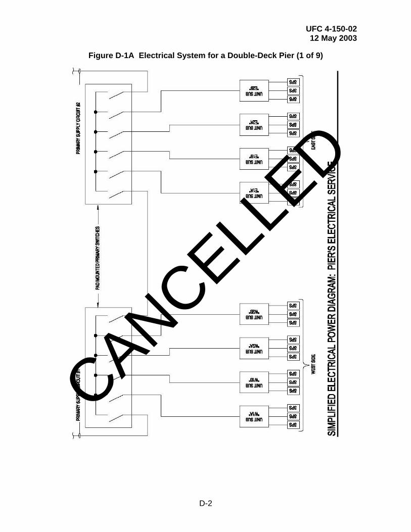
UFC 4-150-02 12 May 2003
D-2
Figure D-1A Electrical System for a Double-Deck Pier (1 of 9)
CANCELLED
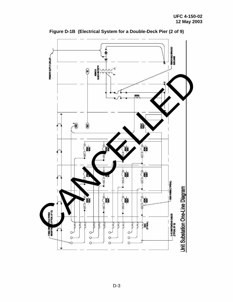
UFC 4-150-02 12 May 2003
D-3
Figure D-1B (Electrical System for a Double-Deck Pier (2 of 9)
CANCELLED
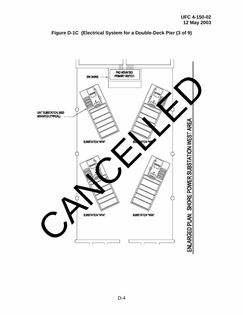
UFC 4-150-02 12 May 2003
D-4
Figure D-1C (Electrical System for a Double-Deck Pier (3 of 9)
CANCELLED
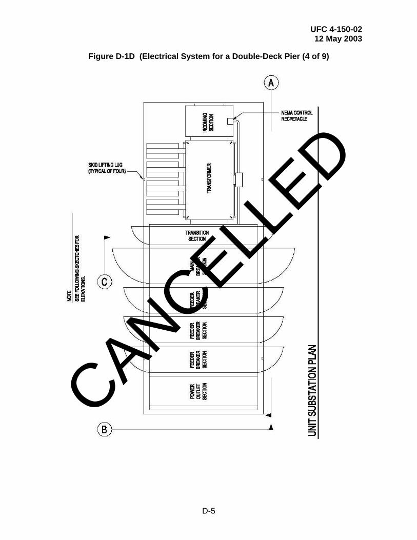
UFC 4-150-02 12 May 2003
D-5
Figure D-1D (Electrical System for a Double-Deck Pier (4 of 9)
CANCELLED

UFC 4-150-02 12 May 2003
D-6
Figure D-1E (Electrical System for a Double-Deck Pier (5 of 9)
CANCELLED
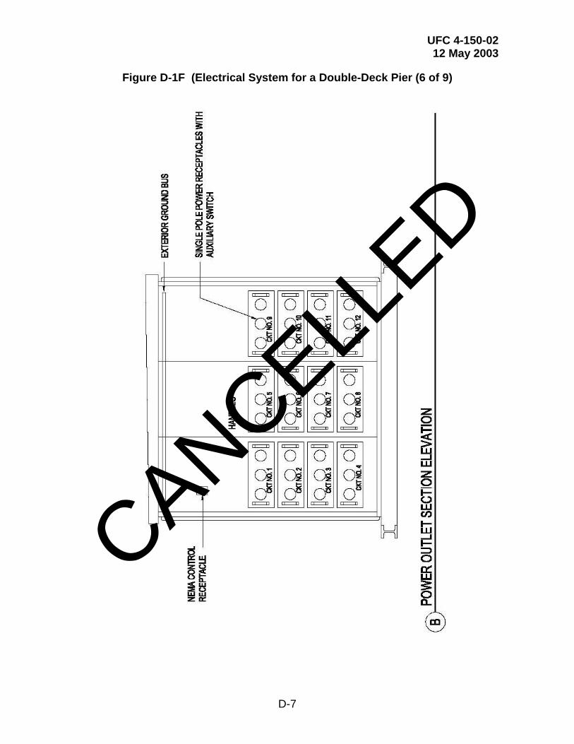
UFC 4-150-02 12 May 2003
D-7
Figure D-1F (Electrical System for a Double-Deck Pier (6 of 9)
CANCELLED

UFC 4-150-02 12 May 2003
D-8
Figure D-1G (Electrical System for a Double-Deck Pier (7 of 9)
CANCELLED
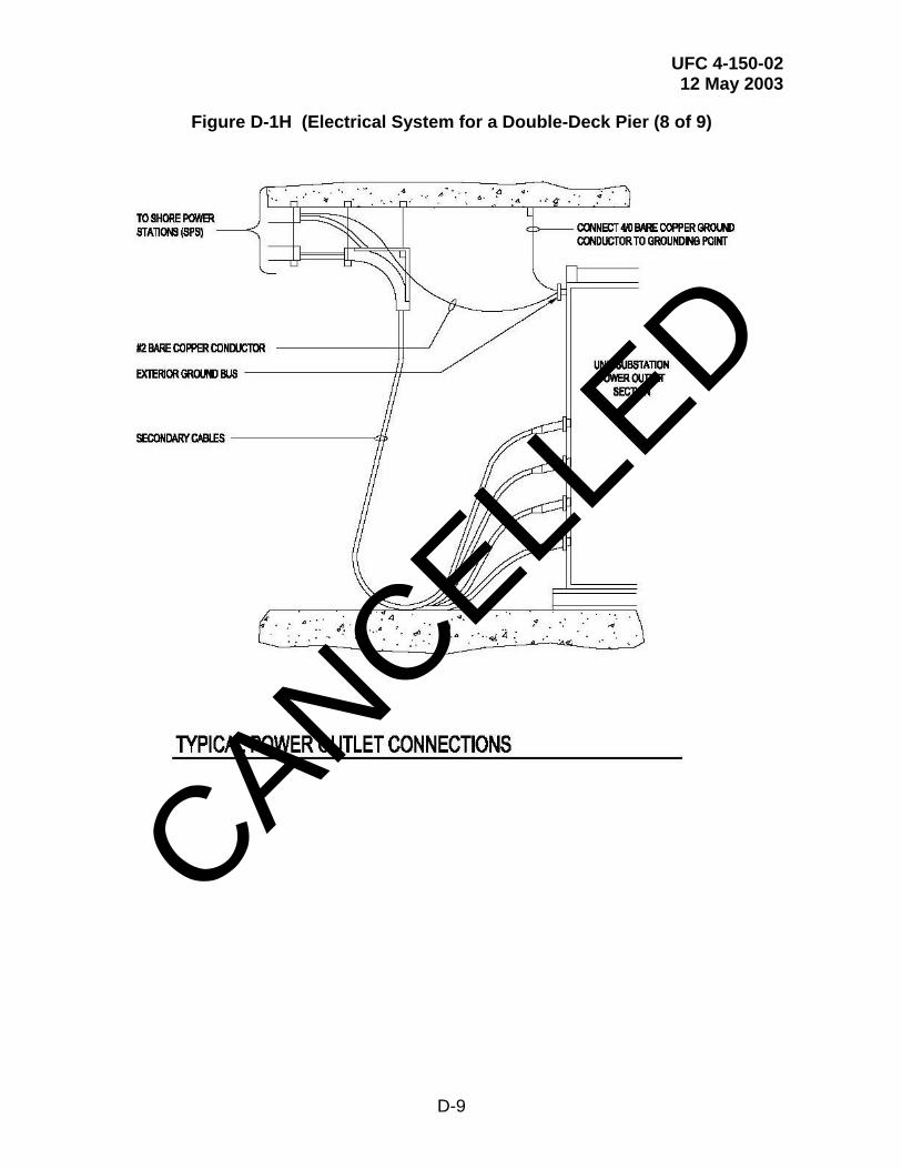
UFC 4-150-02 12 May 2003
D-9
Figure D-1H (Electrical System for a Double-Deck Pier (8 of 9)
CANCELLED
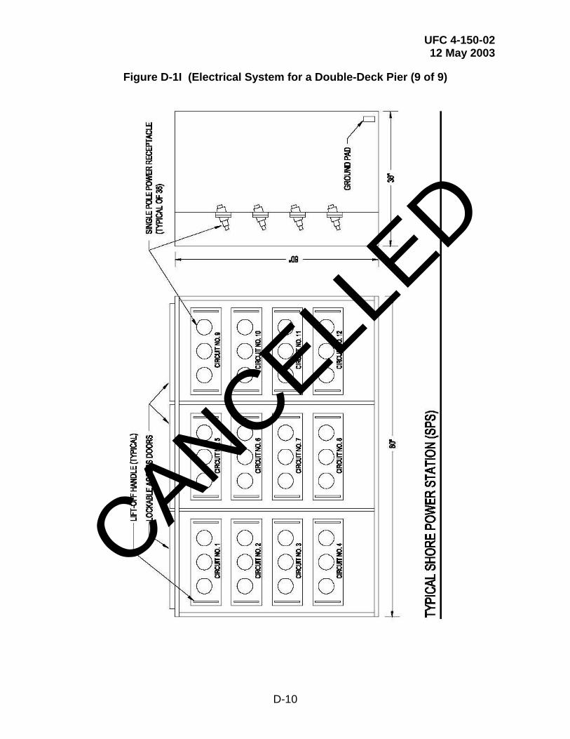
UFC 4-150-02 12 May 2003
D-10
Figure D-1I (Electrical System for a Double-Deck Pier (9 of 9)
CANCELLED
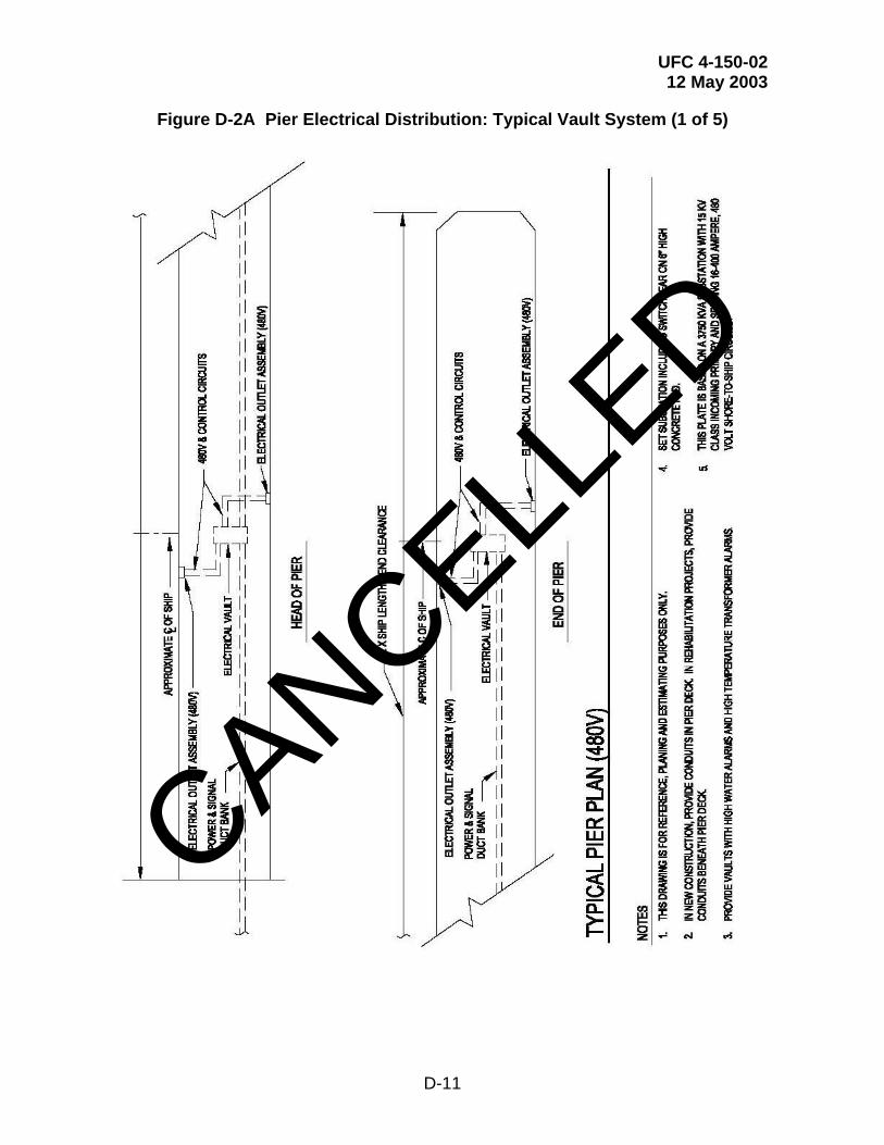
UFC 4-150-02 12 May 2003
D-11
Figure D-2A Pier Electrical Distribution: Typical Vault System (1 of 5)
CANCELLED

UFC 4-150-02 12 May 2003
D-12
Figure D-2B Pier Electrical Distribution: Typical Vault System (2 of 5)
CANCELLED
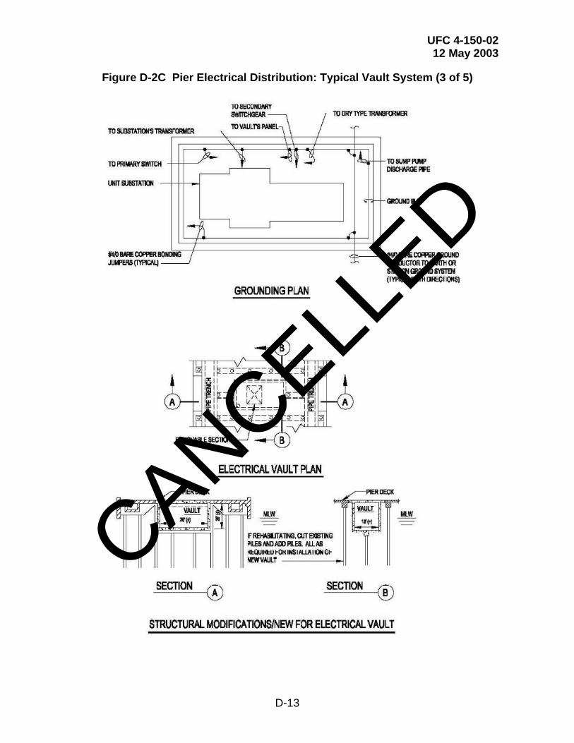
UFC 4-150-02 12 May 2003
D-13
Figure D-2C Pier Electrical Distribution: Typical Vault System (3 of 5)
CANCELLED
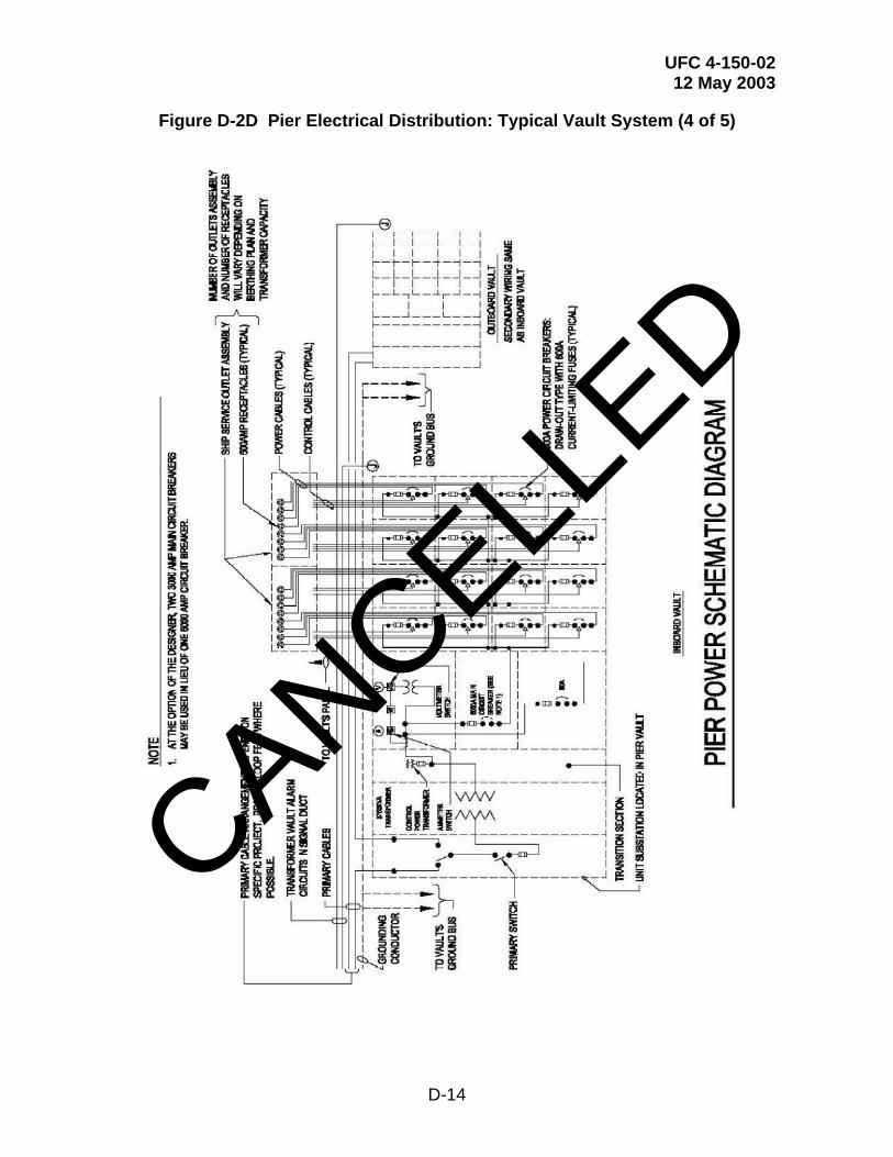
UFC 4-150-02 12 May 2003
D-14
Figure D-2D Pier Electrical Distribution: Typical Vault System (4 of 5)
CANCELLED
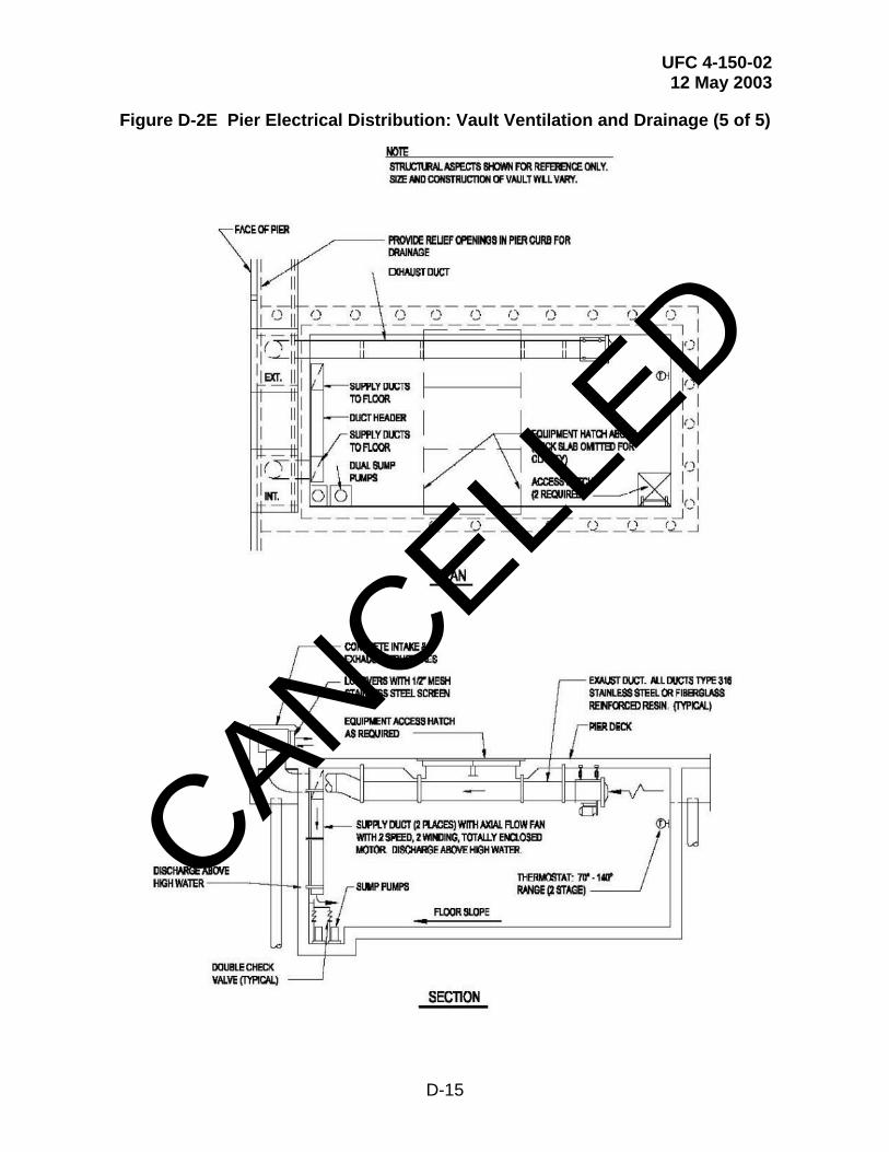
UFC 4-150-02 12 May 2003
D-15
Figure D-2E Pier Electrical Distribution: Vault Ventilation and Drainage (5 of 5)
CANCELLED
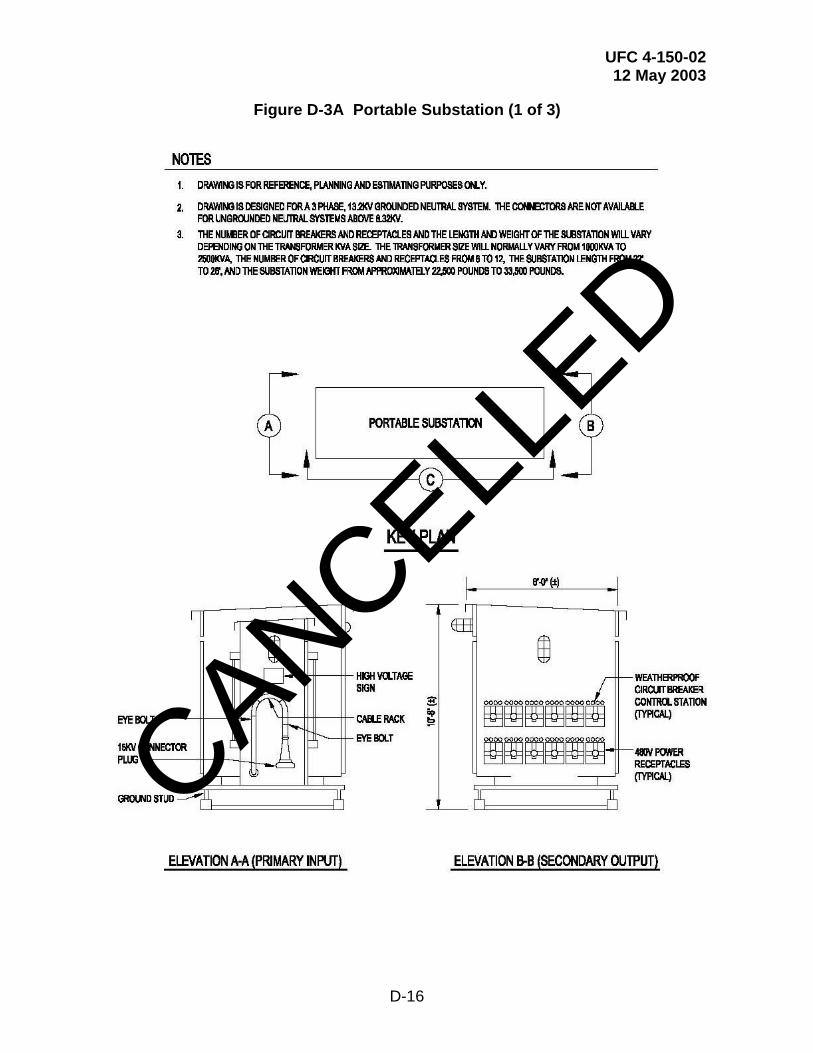
UFC 4-150-02 12 May 2003
D-16
Figure D-3A Portable Substation (1 of 3)
CANCELLED
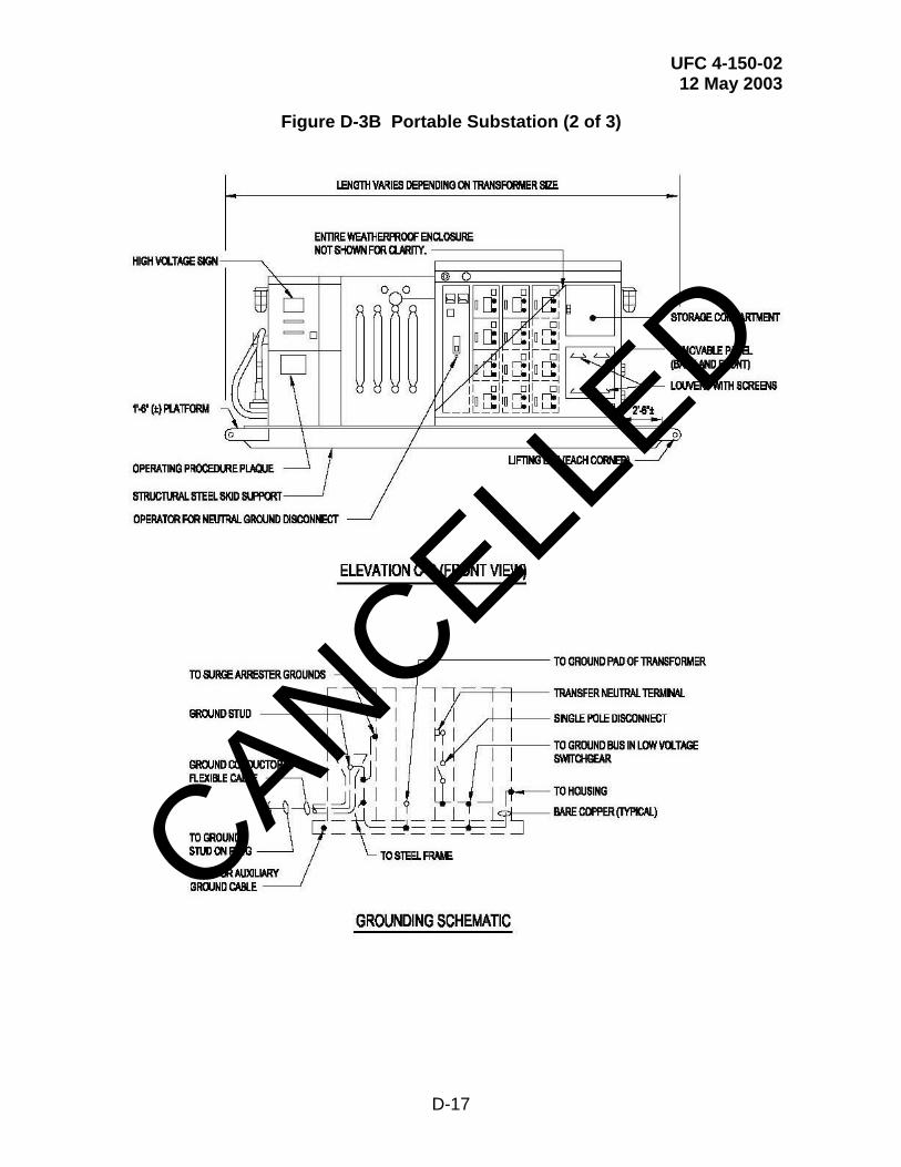
UFC 4-150-02 12 May 2003
D-17
Figure D-3B Portable Substation (2 of 3)
CANCELLED
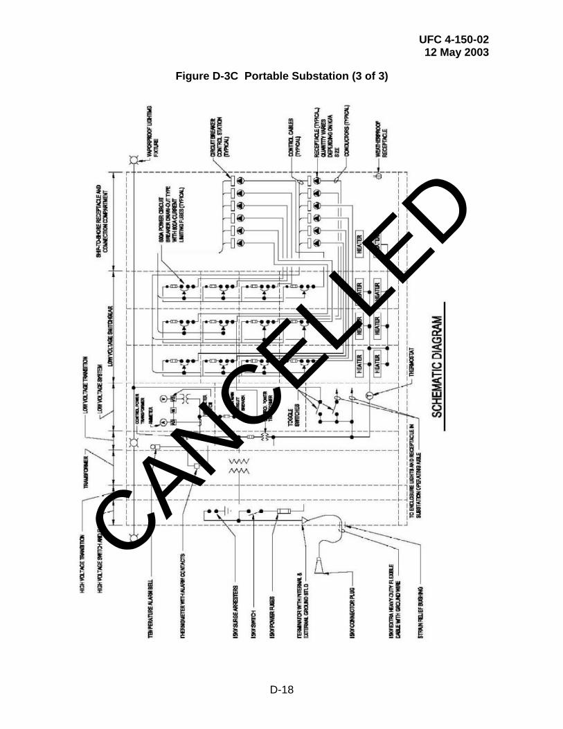
UFC 4-150-02 12 May 2003
D-18
Figure D-3C Portable Substation (3 of 3)
CANCELLED
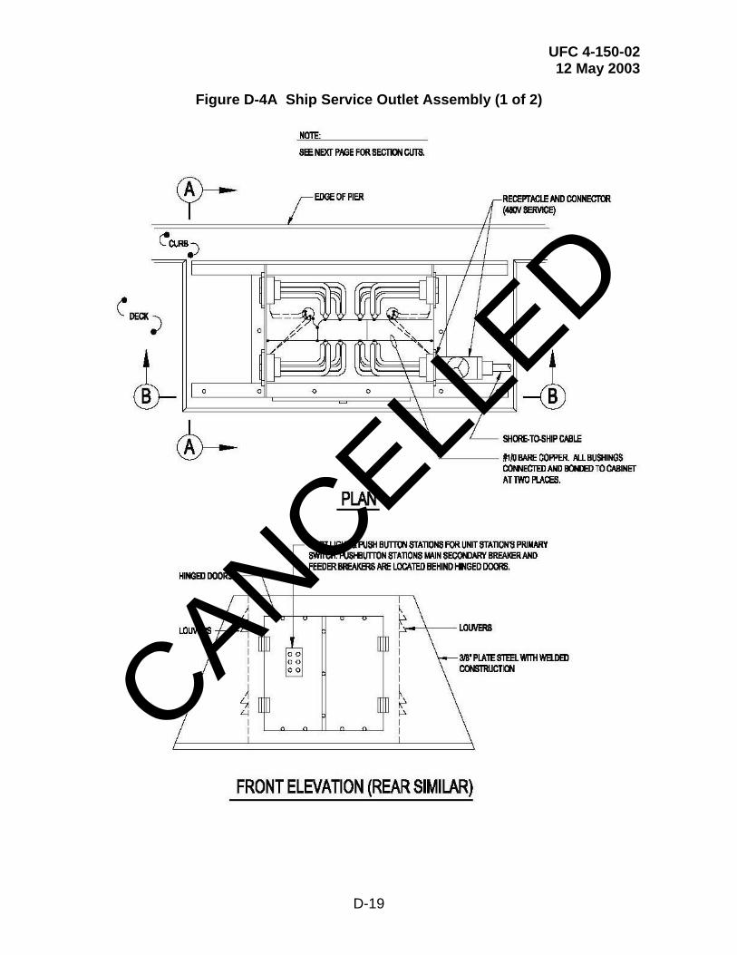
UFC 4-150-02 12 May 2003
D-19
Figure D-4A Ship Service Outlet Assembly (1 of 2)
CANCELLED
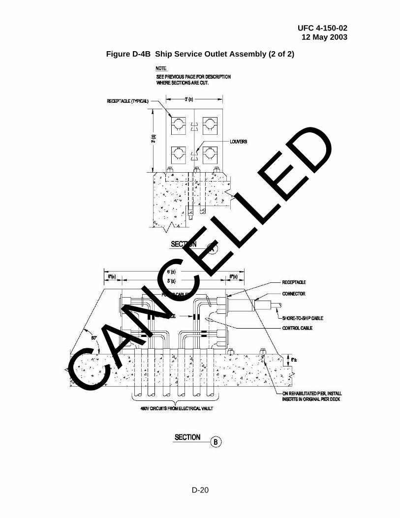
UFC 4-150-02 12 May 2003
D-20
Figure D-4B Ship Service Outlet Assembly (2 of 2)
CANCELLED

UFC 4-150-02 12 May 2003
D-21
Figure D-5A Pier Electrical Distribution for Temporary Services (1 of 3)
CANCELLED
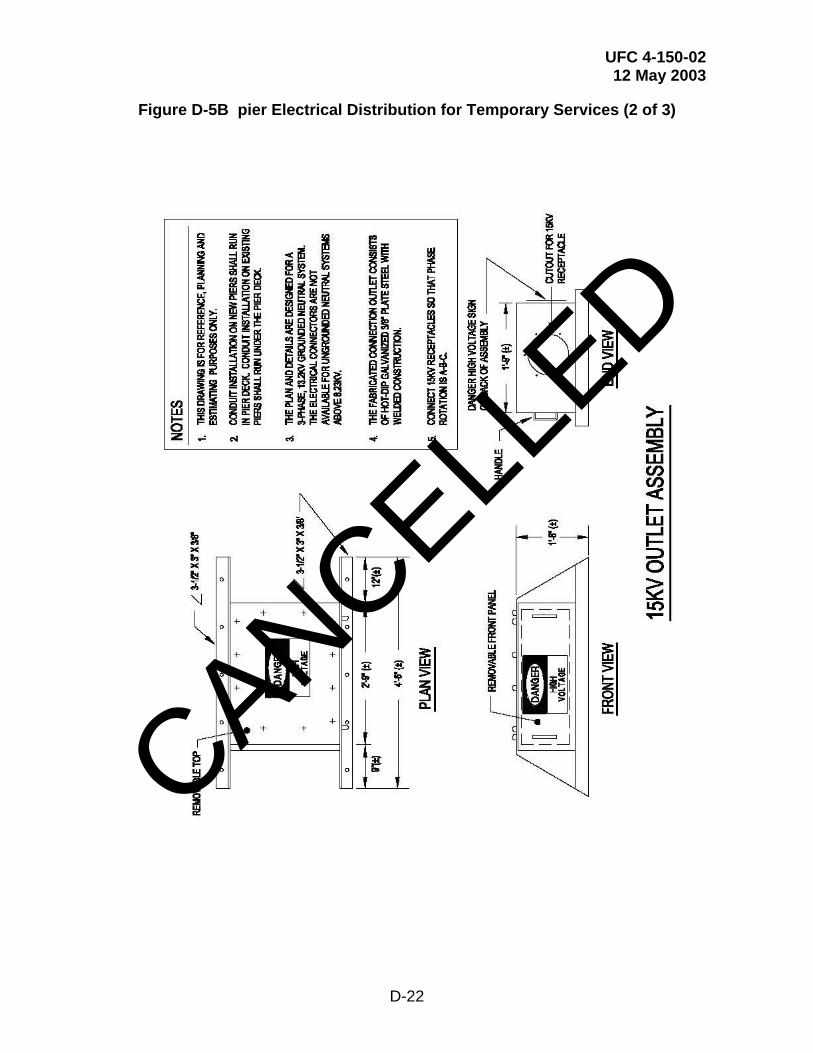
UFC 4-150-02 12 May 2003
D-22
Figure D-5B pier Electrical Distribution for Temporary Services (2 of 3)
CANCELLED

UFC 4-150-02 12 May 2003
D-23
Figure D-5C Pier Electrical Distribution for Temporary Services (3 of 3)
CANCELLED