Embed Size (px)
Citation preview
C H A P T E R
43-1Cisco Unified Communications Manager System Guide
OL-24923-01
43Understanding Video Telephony
Cisco Unified Communications Manager supports video telephony and thus unifies the world of voice and video calls. Video endpoints use Cisco Unified Communications Manager call-handling features and access a unified voice and video solution for dialing and connecting video calls.
The Cisco Unified Communications Manager video telephony solution offers these features:
• Supports video and video-related features, such as far-end camera control (FECC)
• Supports multiple logical channels that are needed to allow the transmission of video streams
• Transmits midcall, media-related messages that are needed for video (that is, transmits commands or indications that are needed for video calls)
• Supports H.323, Skinny Client Control Protocol (SCCP), and Session Initiation Protocol (SIP)
• Enhances locations and regions to provide bandwidth management
• Provides serviceability information, such as Call Detail Records (CDRs), about video calls
This section covers the following topics:
• Video Telephony Configuration Checklist, page 43-2
• Introducing Video Telephony, page 43-4
– Video Calls, page 43-4
– Video Codecs, page 43-5
– Video Network, page 43-6
– Enabling an Audio-Only Device with Video, page 43-7
– H.323 Video, page 43-7
– H.239—Extended Video Channels in H.323 Call, page 43-9
– Skinny Client Control Protocol Video, page 43-13
– Skinny Client Control Protocol Video Bridging, page 43-13
– SIP Video, page 43-14
– Video Encryption, page 43-15
– Presentation Sharing with the Binary Floor Control Protocol, page 43-17
– Bandwidth Management, page 43-19
– Phone Configuration for Video Calls, page 43-21
– Additional Configuration for Video Calls, page 43-22
– Conference Control for Video Conferencing, page 43-22
43-2Cisco Unified Communications Manager System Guide
OL-24923-01
Chapter 43 Understanding Video Telephony Video Telephony Configuration Checklist
– Video and Interoperability, page 43-23
• Video Telephony and Cisco Unified Serviceability, page 43-24
• Where to Find More Information, page 43-26
Video Telephony Configuration ChecklistCisco Unified Communications Manager supports video telephony and thus unifies the world of voice and video calls. Video endpoints use Cisco Unified Communications Manager call-handling features and access a unified voice and video solution for dialing and connecting video calls.
The Cisco Unified Communications Manager video telephony solution offers these features:
• Supports video and video-related features, such as far-end camera control (FECC)
• Supports multiple logical channels that are needed to allow the transmission of video streams
• Transmits midcall, media-related messages that are needed for video (that is, transmits commands or indications that are needed for video calls)
• Supports H.323, Skinny Client Control Protocol (SCCP), and Session Initiation Protocol (SIP)
• Enhances locations and regions to provide bandwidth management
• Provides serviceability information, such as Call Detail Records (CDRs), about video calls
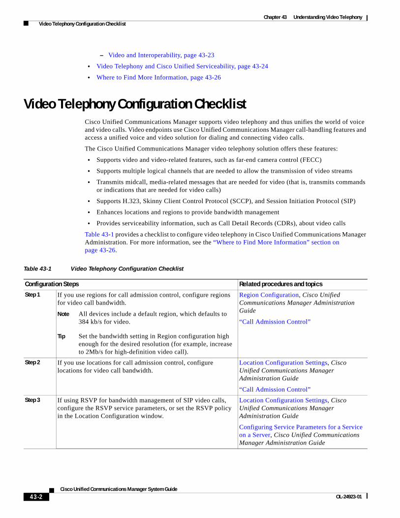
Table 43-1 provides a checklist to configure video telephony in Cisco Unified Communications Manager Administration. For more information, see the “Where to Find More Information” section on page 43-26.
Table 43-1 Video Telephony Configuration Checklist
Configuration Steps Related procedures and topics
Step 1 If you use regions for call admission control, configure regions for video call bandwidth.
Note All devices include a default region, which defaults to 384 kb/s for video.
Tip Set the bandwidth setting in Region configuration high enough for the desired resolution (for example, increase to 2Mb/s for high-definition video call).
Region Configuration, Cisco Unified Communications Manager Administration Guide
“Call Admission Control”
Step 2 If you use locations for call admission control, configure locations for video call bandwidth.
Location Configuration Settings, Cisco Unified Communications Manager Administration Guide
“Call Admission Control”
Step 3 If using RSVP for bandwidth management of SIP video calls, configure the RSVP service parameters, or set the RSVP policy in the Location Configuration window.
Location Configuration Settings, Cisco Unified Communications Manager Administration Guide
Configuring Service Parameters for a Service on a Server, Cisco Unified Communications Manager Administration Guide

43-3Cisco Unified Communications Manager System Guide
OL-24923-01
Chapter 43 Understanding Video Telephony Video Telephony Configuration Checklist
Step 4 To use a Cisco video conference bridge, configure the appropriate conference bridge for your network.
Conference Bridge Configuration, Cisco Unified Communications Manager Administration Guide
Step 5 To configure a user to use the video conference bridge instead of using other conference bridges, configure the media resource groups and media resource group lists for the user accordingly.
Media Resource Group Configuration, Cisco Unified Communications Manager Administration Guide
Media Resource Group List Configuration, Cisco Unified Communications Manager Administration Guide
Step 6 Configure the H.323 gateways in your system to retry video calls as audio calls (default behavior) or configure AAR groups and route/hunt lists to use alternate routing for video calls that do not connect.
Gateway Configuration, Cisco Unified Communications Manager Administration Guide
Automated Alternate Routing Group Configuration, Cisco Unified Communications Manager Administration Guide
Route List Configuration, Cisco Unified Communications Manager Administration Guide
Step 7 Configure the H.323 phones in your system to retry video calls as audio calls (default behavior) or configure AAR groups and route/hunt lists to use alternate routing for video calls that do not connect.
Choose Enabled for Video Capabilities.
Cisco Unified IP Phone Configuration, Cisco Unified Communications Manager Administration Guide
Automated Alternate Routing Group Configuration, Cisco Unified Communications Manager Administration Guide
Route List Configuration, Cisco Unified Communications Manager Administration Guide
Step 8 Configure the H.323 trunks in your system to retry video calls as audio calls (default behavior) or configure AAR groups and route/hunt lists to use alternate routing for video calls that do not connect.
Trunk Configuration, Cisco Unified Communications Manager Administration Guide
Automated Alternate Routing Group Configuration, Cisco Unified Communications Manager Administration Guide
Route List Configuration, Cisco Unified Communications Manager Administration Guide
Table 43-1 Video Telephony Configuration Checklist (continued)
Configuration Steps Related procedures and topics
43-4Cisco Unified Communications Manager System Guide
OL-24923-01
Chapter 43 Understanding Video Telephony Introducing Video Telephony
Introducing Video TelephonyThe following topics discuss the details of video telephony in the Cisco Unified Communications Manager environment:
• Video Calls, page 43-4
• Video Codecs, page 43-5
• Video Network, page 43-6
• H.323 Video, page 43-7
• H.239—Extended Video Channels in H.323 Call, page 43-9
• Skinny Client Control Protocol Video, page 43-13
• Skinny Client Control Protocol Video Bridging, page 43-13
• SIP Video, page 43-14
• Bandwidth Management, page 43-19
• Phone Configuration for Video Calls, page 43-21
• Additional Configuration for Video Calls, page 43-22
• Conference Control for Video Conferencing, page 43-22
Video CallsThe typical video call includes two or three Real-Time Protocol (RTP) streams in each direction (that is, four or six streams). The call can include the following stream types:
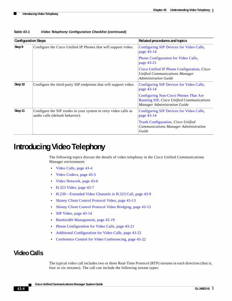
Step 9 Configure the Cisco Unified IP Phones that will support video. Configuring SIP Devices for Video Calls, page 43-14
Phone Configuration for Video Calls, page 43-21
Cisco Unified IP Phone Configuration, Cisco Unified Communications Manager Administration Guide
Step 10 Configure the third-party SIP endpoints that will support video. Configuring SIP Devices for Video Calls, page 43-14
Configuring Non-Cisco Phones That Are Running SIP, Cisco Unified Communications Manager Administration Guide
Step 11 Configure the SIP trunks in your system to retry video calls as audio calls (default behavior).
Configuring SIP Devices for Video Calls, page 43-14
Trunk Configuration, Cisco Unified Communications Manager Administration Guide
Table 43-1 Video Telephony Configuration Checklist (continued)
Configuration Steps Related procedures and topics
43-5Cisco Unified Communications Manager System Guide
OL-24923-01
Chapter 43 Understanding Video Telephony Introducing Video Telephony
• Video (H.261, H.263, H.263+, H.264, and Cisco VT Camera wideband video codecs) at a different port
• Far-end camera control (FECC) (optional)
Call control for video calls operates the same way as the call control that governs all other calls. See the “Call Control” section on page 22-3.
Note See “Intelligent Bridge Selection” section on page 24-18 for details on how Cisco Unified Communications Manager can allocate a video conference bridge automatically.
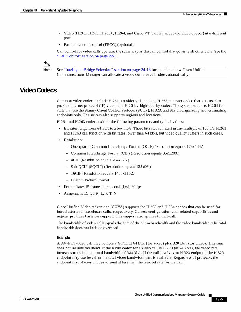
Video CodecsCommon video codecs include H.261, an older video codec, H.263, a newer codec that gets used to provide internet protocol (IP) video, and H.264, a high-quality codec. The system supports H.264 for calls that use the Skinny Client Control Protocol (SCCP), H.323, and SIP on originating and terminating endpoints only. The system also supports regions and locations.
H.261 and H.263 codecs exhibit the following parameters and typical values:
• Bit rates range from 64 kb/s to a few mb/s. These bit rates can exist in any multiple of 100 b/s. H.261 and H.263 can function with bit rates lower than 64 kb/s, but video quality suffers in such cases.
• Resolution:
– One-quarter Common Interchange Format (QCIF) (Resolution equals 176x144.)
– Common Interchange Format (CIF) (Resolution equals 352x288.)
– 4CIF (Resolution equals 704x576.)
– Sub QCIF (SQCIF) (Resolution equals 128x96.)
– 16CIF (Resolution equals 1408x1152.)
– Custom Picture Format
• Frame Rate: 15 frames per second (fps), 30 fps
• Annexes: F, D, I, J,K, L, P, T, N
Cisco Unified Video Advantage (CUVA) supports the H.263 and H.264 codecs that can be used for intracluster and intercluster calls, respectively. Correct configuration with related capabilities and regions provides basis for support. This support also applies to mid-call.
The bandwidth of video calls equals the sum of the audio bandwidth and the video bandwidth. The total bandwidth does not include overhead.
Example
A 384-kb/s video call may comprise G.711 at 64 kb/s (for audio) plus 320 kb/s (for video). This sum does not include overhead. If the audio codec for a video call is G.729 (at 24 kb/s), the video rate increases to maintain a total bandwidth of 384 kb/s. If the call involves an H.323 endpoint, the H.323 endpoint may use less than the total video bandwidth that is available. Regardless of protocol, the endpoint may always choose to send at less than the max bit rate for the call.

43-6Cisco Unified Communications Manager System Guide
OL-24923-01
Chapter 43 Understanding Video Telephony Introducing Video Telephony
Video NetworkFigure 43-1 provides an example of a video network that uses a single Cisco Unified Communications Manager cluster. In a successful video network, any endpoint can call any other endpoint. Video availability only exists if both endpoints are video enabled. Video capabilities extend across trunks.
Figure 43-1 Video Network Example
The Cisco video conference portfolio comprises the following video bridges:
• Cisco TelePresence MCU series
• ISRG2 ad hoc video conference service
• MeetingPlace
See “Conference Bridge Configuration” in the Cisco Unified Communications Manager Administration Guide for details of configuring the Cisco video conferencing options in Cisco Unified Communications Manager Administration.
The Cisco UC Endpoints portfolio comprises the following endpoints that support video:
• Cisco Unified IP Phone 9971
• Cisco Unified IP Phone 9951
• Cisco Unified IP Phone 8941
• Cisco Unified IP Phone 8945
• Cisco Unified IP Phone 7985
IP
PSTN
H.320/H.323Gateway
H.323 MCU
IOS Gatekeeper
H.323 VideoSystem
H.323
2550
41
Cisco UnifiedCommunicationsManager Cluster
Trunk
UC Endpoints
Video BridgeCTS
Trunk
CTMS
H.323Endpoints
SIPSIPEndpoints
VideoCommunication
Server
Trunk
43-7Cisco Unified Communications Manager System Guide
OL-24923-01
Chapter 43 Understanding Video Telephony Introducing Video Telephony
• Cisco IP Video Phone E20
• Cisco TelePresence EX60
• Cisco TelePresence EX90
• Cisco TelePresence Quick Set C20
• Cisco TelePresence Codec C40
• Cisco TelePresence Codec C60
• Cisco TelePresence Codec C90
For more information, refer to the applicable IP phone user and administration guide.
Note Third-party SIP video endpoints are capable of connecting to Cisco Unified Communications Manager as a line-side device or as a trunk-side device. For more information, see Third-Party SIP Endpoints, page 42-21.
Enabling an Audio-Only Device with VideoYou can enable an audio-only device with video by using a Cisco application, Cisco Unified Video Advantage. You can associate the application with a Cisco Unified IP Phone in order to display the video component on your PC or laptop. This association can occur before a call is made or during a call (mid-call). Cisco Unified IP Phones, such as 7975, 7940, 7960, 7975, 6961, 6941, and 6921 support Cisco Unified Video Advantage.
For example, a call occurs from a Cisco Unified IP Phone 7975 to a video phone. The call gets established as audio only. After Cisco Unified Video Advantage is associated with the Cisco Unified IP Phone 7975, the call gets reestablished as a video call.
During the association, Cisco Unified Communications Manager receives updated capabilities for the phone via existing SCCP messages. After the updated capabilities are received, Cisco Unified Communications Manager negotiates for video.
If the initial call involves an IP phone without a video, only audio location bandwidth gets reserved, and the media layer establishes an audio-only call.
In addition to audio phones, Cisco video phones, such as 9971 and 9951 also support Cisco Unified Video Advantage.
H.323 VideoH.323 video exhibits the following characteristics:
• H.323 endpoints can be configured as H.323 phones, H.323 gateways, or H.323 trunks.
• Call forwarding, dial plan, and other call-routing-related features work with H.323 endpoints.
• H.323 video endpoints cannot initiate hold, resume, transfer, park, and other similar features.
• If an H.323 endpoint supports the empty capability set (ECS), the endpoint can be held, parked, and so forth.
• Some vendors implement call setup in such a way that they cannot increase the bandwidth of a call when the call gets transferred or redirected. In such cases, if the initial call is audio, users may not receive video when they are transferred to a video endpoint.
43-8Cisco Unified Communications Manager System Guide
OL-24923-01
Chapter 43 Understanding Video Telephony Introducing Video Telephony
• No video media termination point (MTP) nor video transcoder currently exists. If an audio transcoder or MTP is inserted into a call, that call will be audio only. This is true when the IPVC audio transcoding capabilities is not being used. When the IPVC transcoders are used, you can transcode the audio and send/receive video.
• For H.323 video calls, users must specify video call bandwidth.
Dynamic H.323 AddressingYou can configure a H.323 client with the E.164 address that is registered with the gatekeeper. E.164 addressing facilitates H.323 configuration and call routing by allowing the Cisco Unified Communications Manager to route all calls in place of the gatekeeper. The gatekeeper that is to be configured requires the following characteristics:
• Forward all calls to the Cisco Unified Communications Manager for routing.
• Calls that are routed from the Cisco Unified Communications Manager must not be routed back to the Cisco Unified Communications Manager.
Registering with the Gatekeeper
At boot time, Cisco Unified Communications Manager loads static configuration information such as the E.164 address and the configured gatekeeper for each H.323 client. The H.323 clients in the same gatekeeper zone stay in one group. A registration with the gatekeeper gets initiated for the group. The process does not require individual registration for each member of the group.
H.323 clients that belong to the same gatekeeper and zone belong to the same group, and only one registration is initiated for this group. H.323 devices that belong to the same gatekeeper as the first group but to a different gatekeeper zone are part of another group, and only one registration is initiated for this group. All members of the same group use the same technology prefix.
Call Processing
During an outbound call where the H.323 client is the called party, Cisco Unified Communications Manager routes the call on the basis of DN to the H.323 device. Cisco Unified Communications Manager uses the H.323 device configuration to determine whether the gatekeeper is configured and sends an Admission Request Message (ARQ) with the configured E.164 address. If the device is registered with the gatekeeper, the gatekeeper sends an Admission Confirm Message (ACF) with the device's current IP address. Cisco Unified Communications Manager routes the call directly to this address.
During an inbound call where the H.323 device is the calling party, the gatekeeper routes the call to Cisco Unified Communications Manager. Cisco Unified Communications Manager uses the source E.164 address to determine whether the calling device is configured. Cisco Unified Communications Manager uses the configuration to determine the configuration for that phone. The phone configuration includes regions, locations, MRGL, and so on.
Be aware of the following items:
• The system does not support E.164 addressing on H.323 trunks, intercluster trunks, and H.323 gateways.
• Cisco Unified Communications Manager does not resolve the device name when a gatekeeper-controlled H.323 client is configured. Cisco Unified Communications Manager can access the gatekeeper field for the H.323 client to discover the device. This enables Cisco Unified Communications Manager to bypass name resolution for the device name.
43-9Cisco Unified Communications Manager System Guide
OL-24923-01
Chapter 43 Understanding Video Telephony Introducing Video Telephony
• Cisco Unified Communications Manager supports a maximum of one E.164 number per gatekeeper-controlled H.323 client. If the gatekeeper field is populated, you cannot configure a second DN. If an H.323 client is configured for more than one DN, you cannot add the extra gatekeeper information to the database.
• The Gatekeeper routes call by using zone information when there is no zone prefix.
Configuration Notes
Be aware of the following items for configuration purposes:
• You must ensure that gatekeeper is configured in Cisco Unified Communications Manager before an H.323 client can specify that gatekeeper in its configuration. The Gatekeeper field stays empty by default.
• Be sure to add the gatekeeper name, technology prefix, zone, and E.164 fields to the H.323 client configuration. You do not need to add Terminal Type. Default specifies the gateway type. If the gatekeeper is not chosen for the gatekeeper field during configuration of each of these fields, these fields cannot populate.
• Gatekeeper, zone, technology prefix fields, and E.164 information display under the Gatekeeper Information group on H.323 Client configuration.
• When an H.323 client uses the same gatekeeper, zone and technology prefix as those of another client, consider both clients in the same group. This group represents a single endpoint to the gatekeeper.
• You cannot use the same zone name for the H.323 client and trunk. A zone that an H.323 client uses must differ from the one that an H.323 trunk or a gatekeeper-controlled intercluster trunk uses.
• Ensure the service parameter, Send Product Id and Version ID, is set to True.
If an H.323 client is configured with an E.164 address and a gatekeeper, the database stores this information when the configuration is updated. This information gets loaded at boot time or when the device is reset.
H.239—Extended Video Channels in H.323 CallThe extended video channels feature works via H.239 protocol and enables multiple video channel support. Cisco Unified Communications Manager supports negotiating an extended video channel using the H.239 protocol in direct point-to-point H.323 calls. This also includes calls across the H.323 intercluster trunk.
Cisco Unified Communications Manager supports all H.239 associated support signals and commands that are specified in the H.239 recommendation.
The following characteristics apply to the extended video channels feature:
• Support for Third-Party H.323 Devices, page 43-10
• H.323 Devices Invoke Presentation Feature, page 43-10
• Opening Second Video Channels, page 43-11
• Call Admission Control (CAC) on Second Video Channels, page 43-11
• Number of Video Channels Allowed, page 43-12
• H.239 Commands and Indication Messages, page 43-12
• Topology and Protocol Interoperability Limitation, page 43-13

43-10Cisco Unified Communications Manager System Guide
OL-24923-01
Chapter 43 Understanding Video Telephony Introducing Video Telephony
• Midcall Feature Limitation, page 43-13
Support for Third-Party H.323 Devices
The extended video channel feature supports H.239 interoperability among third-party video endpoints and Cisco Unified Voice Conferencing. Cisco Unified Communications Manager allows an extended video channel to be used for presentation and live meeting transmission. This feature focuses on multiple video channel support via H.245 signaling. The following presentation applications provide basis for this multichannel support:
• Natural Presenter package by the third-party vendor Tandberg
• People + Content by the third-party vendor Polycom
Both Natural Presenter package and People + Content use the H.239 protocol to negotiate capabilities and define the roles of the additional video channels.
Note Natural Presenter package by Tandberg and People + Content by Polycom only support H.239 for the presentation mode.
Note Be aware that the presentation applications that are offered by Tandberg and Polycom are optional features. You must have one of these options and H.239 enabled in both caller and callee endpoints to negotiate second video channels or the call will be limited to a single video channel.
H.323 Devices Invoke Presentation Feature
Tandberg and Polycom video endpoints allow the user to share presentation materials from various components (for example, VCR, Projector, PC, and so on). The components can physically connect with the endpoints, and the PC can also run presentation applications that are provided by the vendor to transmit the presentation image. The source of presentation and the component connection with the video endpoint are irrelevant to the mechanism of establishing video channels by using H.239.
Note For details on setting up presentation sources, see the video endpoint user guide.
When two H.239-enabled endpoints attempt to establish a video call, they declare their video capabilities for the main video channel for meeting participants and their extended video capabilities (H.239 capabilities) for the second video channel. The following contents comprise H.239 capability signals:
1. The endpoints send signals to indicate that the devices support H.239. They also send associated commands and indication signals for managing the second video channel. This enables both the endpoints to be aware that the call is capable of opening multiple video channels.
2. The endpoints sends out one or more extended video codec capabilities to express video codec capabilities for second channels. The endpoint must specify the role of the second video channel. The defined role labels can be
– Live-video—This channel gets processed normally and is suitable for live video of people
– Presentation—This channel relays a token-managed presentation that is distributed to the devices
43-11Cisco Unified Communications Manager System Guide
OL-24923-01
Chapter 43 Understanding Video Telephony Introducing Video Telephony
After the capabilities have been exchanged, both endpoints immediately open two-way audio channels and the main video channels as in the traditional video calls.
Opening Second Video Channels
Depending on the third-party endpoint implementation, the second video channel is handled differently among vendors.
Natural Presenter Package by Tandberg
Tandberg initiates the second video channel on demand. A Tandberg device does not open the second video channel immediately after the main video channel is established. The second channel gets opened when one of the callers (the presenter) specifies the source of the presentation and invokes a command to start the presentation.
When a Tandberg user decides to start sharing the presentation, Tandberg requests the other call party to open an extended video channel for receiving the presentation image; therefore, a Tandberg-Tandberg call has only one-way second video channel.
People + Content by Polycom
Unlike Tandberg, a Polycom video endpoint initiates the second video endpoint immediately as a part of the default mechanism, after both parties have confirmed that additional video channels can be supported.
Note The channel established gets automatically if both parties support H.239 and have the extended video channel feature enabled. However, the additional channel does not show anything until one of the parties start to share presentation.
Polycom initiates a request for the second video channel to the other call party regardless of the usage of the second video channel; therefore, in a Polycom-Polycom call, two-way video channels get opened between the devices even if only one of them sends out presentation image/video.
This implementation ensures that both call parties have the second video channel ready for transmission when the call parties decide to take the token to present something. Although one of the two video channels remains idle (not sending anything), the Polycom device controls bandwidth to ensure load efficiency.
Note This difference in handling second video channels does not affect the implementation of H.239. Cisco Unified Communications Manager does not initiate any receiving channel request in an H.323-H.323 call. Cisco Unified Communications Manager simply relays all channel requests from one terminal to another.
Note Cisco Unified Communications Manager does not enforce two-way transmission for the second set of video channels because this does not represent a requirement in the H.239 protocol.
Call Admission Control (CAC) on Second Video Channels
The following call admission control policies of Cisco Unified Communications Manager get applied to the second video channels:

43-12Cisco Unified Communications Manager System Guide
OL-24923-01
Chapter 43 Understanding Video Telephony Introducing Video Telephony
Cisco Unified Communications Manager restricts the bandwidth usage by the second video channels on the basis of location configuration. When the second video channel is being established, Cisco Unified Communications Manager makes sure that enough video bandwidth stays available within the location pool and reserves bandwidth accordingly. If the required bandwidth is not available, Cisco Unified Communications Manager instructs the channel to reduce the available bandwidth to zero.
No change occurs in the region configuration or policies to support the second video channels.
Traditionally, Cisco Unified Communications Manager region policy has only supported a call with a single video channel and the total bandwidth usage of this call never gets larger than what the region configuration specifies.
If the administrator sets a finite region video bandwidth restriction for an H.239 call, Cisco Unified Communications Manager will violate the region policy because the region value will get used against the bandwidth that is requested for each video channel independently.
Example:If the region video bandwidth is set to 384Kbps and the audio channel uses 64Kb/s, the maximum allowed bandwidth for each video channel will be (384Kb/s - 64Kb/s)= 320Kb/s. i.e. the maximum bandwidth to be used by the H.239 call will be (audio bw + 2*(384 - audio bw)) = 704Kb/s, which goes beyond the 384Kb/s bandwidth that the region specifies.
Note You should consider relaxing both region and location bandwidth restrictions for H.239 calls, so the H.239 devices are allowed to readjust and balance load for both the video channels without Cisco Unified Communications Manager intervention.
Number of Video Channels Allowed
Cisco Unified Communications Manager 8.5(1) supports only a maximum of two video channels due to the following reasons:
• Both Tandberg and Polycom only support two video channels, one of which is for main video, and the other is for presentation.
• H.239 only defines an Additional Media Channel (AMC) for H.320-based system to partition the traditional H.320 video channel for the purpose of presentation.
H.239 Commands and Indication Messages
Command and Indication (C&I) messages get used for H.239 to manage tokens for the Presentation and Live roles and to permit devices to request release of video flow control to enable the operation of additional media channels. Cisco Unified Communications Manager supports all the C & I messages. Whenever Cisco Unified Communications Manager receives C&I messages, it relays them to the call party accordingly.
Be aware that the flow control release request and response messages can be used to request that the far end release flow control, so it allows an endpoint to send the indicated channel at the indicated bit rate.
Note Be aware that the call party may or may not honor the request as is indicated by flow control release response.

43-13Cisco Unified Communications Manager System Guide
OL-24923-01
Chapter 43 Understanding Video Telephony Introducing Video Telephony
The Presentation role token messages allow an H.239 device to acquire the token for presentation. The other call party may accept or reject the request. The presenter device sends out a token release message when it is no longer needed.
Topology and Protocol Interoperability Limitation
Cisco Unified Communications Manager 8.5(1) supports only H.239 in H.323 to H.323 calls. Cisco Unified Communications Manager allows H.239 calls to be established across H.323 intercluster trunk or multiple nodes. If an H.239-enabled device attempts to make a call with a non-H323 end, the H.239 capabilities will get ignored and the call will get conducted like the traditional video calls that are supported by Cisco Unified Communications Manager.
Cisco Unified Communications Manager does not support a second video channel when a media termination point or transcoder is inserted into the call. If it happens, the call will fall back to normal video calls.
Midcall Feature Limitation
Cisco Unified Communications Manager supports opening second video channels only in direct H.323 to H.323 calls.
Warning Do not attempt to invoke any midcall features such as call transfer or hold/resume operations. Doing so can lead to problems and the second video channel can get disconnected.
Skinny Client Control Protocol VideoSkinny Client Control Protocol video exhibits the following characteristics:
• If a phone that is running Skinny Client Control Protocol reports video capabilities, Cisco Unified Communications Manager automatically opens a video channel if the other end supports video.
• For Skinny Client Control Protocol video calls, system administration determines video call bandwidth by using regions. The system does not ask users for bit rate.
Skinny Client Control Protocol Video BridgingVideo conferencing requires a Skinny Client Control Protocol video bridge. Skinny Client Control Protocol video bridging exhibits the following characteristics:
• Skinny Client Control Protocol video bridging requires the same setup as an audio bridge.
• Skinny Client Control Protocol video bridging supports a mix of audio and video in a conference.
• Media resource group lists determine whether an endpoint receives an audio or video bridge. That is, the media resource group list configuration of the user who sets up the conference determines whether the conference is a video conference or an audio-only conference. See the “Media Resource Group List Configuration” chapter of the Cisco Unified Communications Manager Administration Guide for details on configuring a media resource group list.
43-14Cisco Unified Communications Manager System Guide
OL-24923-01
Chapter 43 Understanding Video Telephony Introducing Video Telephony
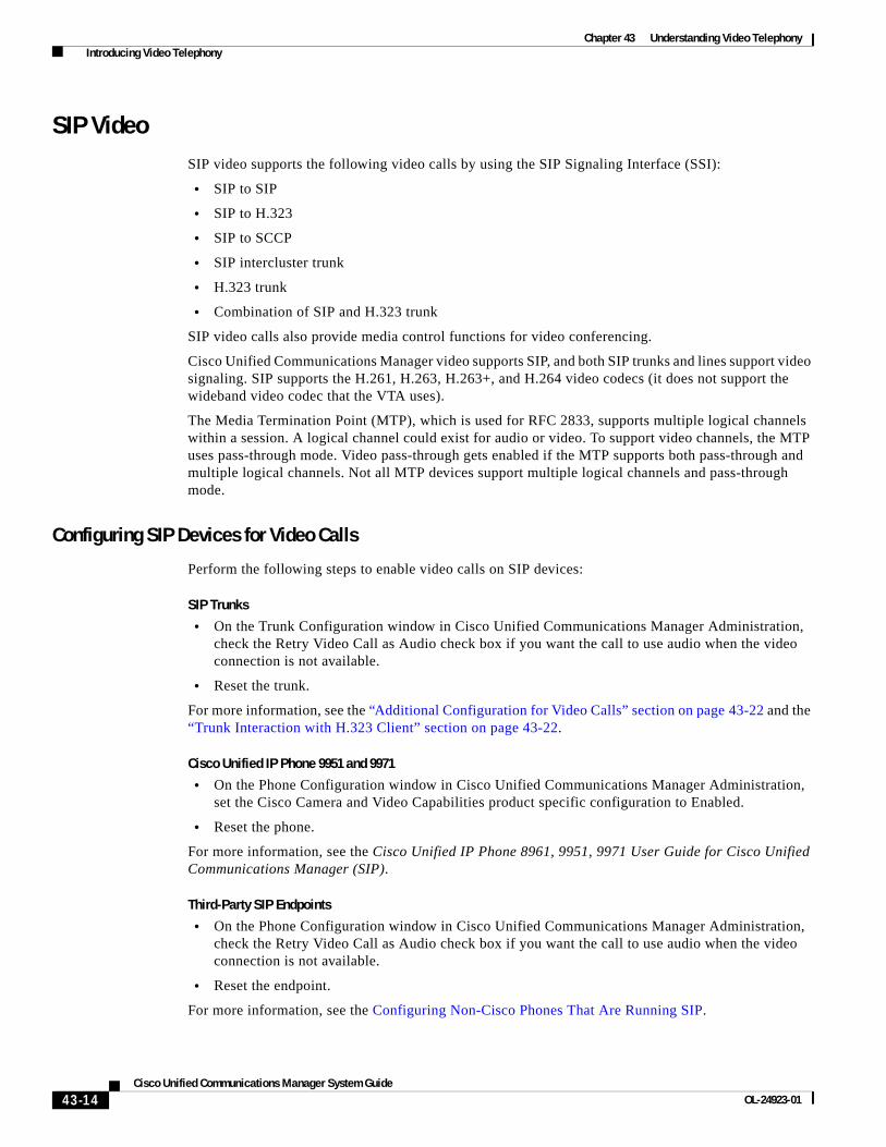
SIP VideoSIP video supports the following video calls by using the SIP Signaling Interface (SSI):
• SIP to SIP
• SIP to H.323
• SIP to SCCP
• SIP intercluster trunk
• H.323 trunk
• Combination of SIP and H.323 trunk
SIP video calls also provide media control functions for video conferencing.
Cisco Unified Communications Manager video supports SIP, and both SIP trunks and lines support video signaling. SIP supports the H.261, H.263, H.263+, and H.264 video codecs (it does not support the wideband video codec that the VTA uses).
The Media Termination Point (MTP), which is used for RFC 2833, supports multiple logical channels within a session. A logical channel could exist for audio or video. To support video channels, the MTP uses pass-through mode. Video pass-through gets enabled if the MTP supports both pass-through and multiple logical channels. Not all MTP devices support multiple logical channels and pass-through mode.
Configuring SIP Devices for Video Calls
Perform the following steps to enable video calls on SIP devices:
SIP Trunks
• On the Trunk Configuration window in Cisco Unified Communications Manager Administration, check the Retry Video Call as Audio check box if you want the call to use audio when the video connection is not available.
• Reset the trunk.
For more information, see the “Additional Configuration for Video Calls” section on page 43-22 and the “Trunk Interaction with H.323 Client” section on page 43-22.
Cisco Unified IP Phone 9951 and 9971
• On the Phone Configuration window in Cisco Unified Communications Manager Administration, set the Cisco Camera and Video Capabilities product specific configuration to Enabled.
• Reset the phone.
For more information, see the Cisco Unified IP Phone 8961, 9951, 9971 User Guide for Cisco Unified Communications Manager (SIP).
Third-Party SIP Endpoints
• On the Phone Configuration window in Cisco Unified Communications Manager Administration, check the Retry Video Call as Audio check box if you want the call to use audio when the video connection is not available.
• Reset the endpoint.
For more information, see the Configuring Non-Cisco Phones That Are Running SIP.
43-15Cisco Unified Communications Manager System Guide
OL-24923-01
Chapter 43 Understanding Video Telephony Introducing Video Telephony
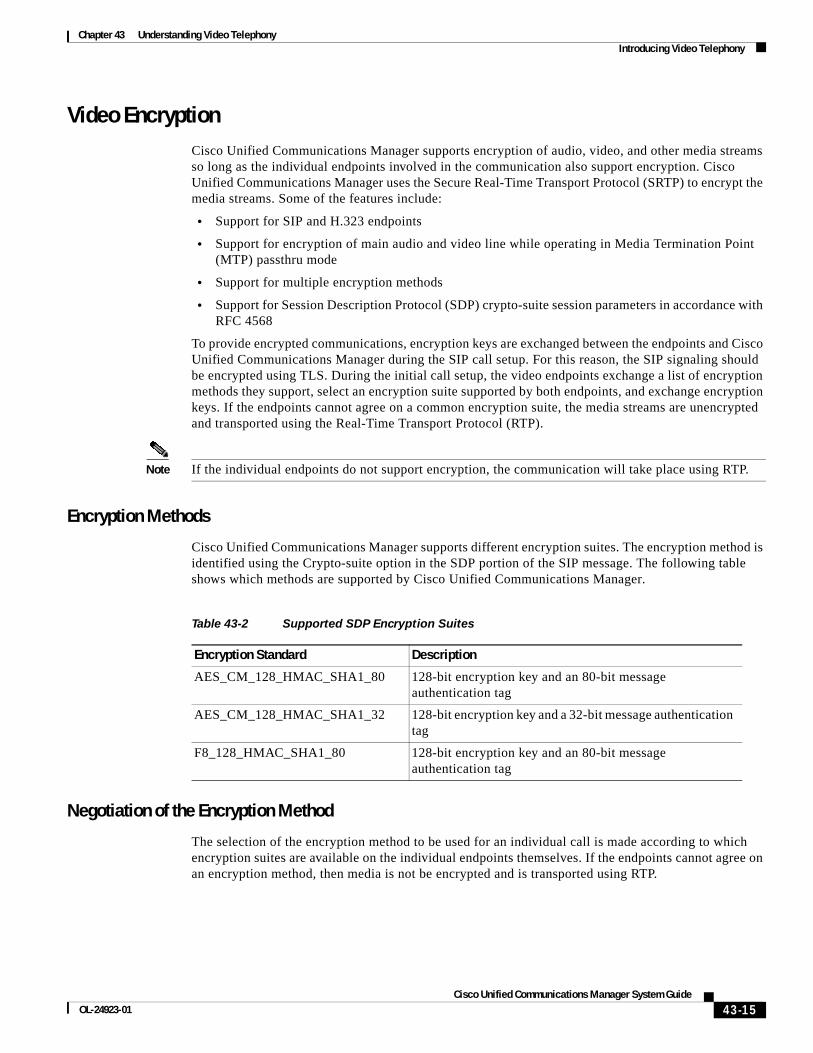
Video EncryptionCisco Unified Communications Manager supports encryption of audio, video, and other media streams so long as the individual endpoints involved in the communication also support encryption. Cisco Unified Communications Manager uses the Secure Real-Time Transport Protocol (SRTP) to encrypt the media streams. Some of the features include:
• Support for SIP and H.323 endpoints
• Support for encryption of main audio and video line while operating in Media Termination Point (MTP) passthru mode
• Support for multiple encryption methods
• Support for Session Description Protocol (SDP) crypto-suite session parameters in accordance with RFC 4568
To provide encrypted communications, encryption keys are exchanged between the endpoints and Cisco Unified Communications Manager during the SIP call setup. For this reason, the SIP signaling should be encrypted using TLS. During the initial call setup, the video endpoints exchange a list of encryption methods they support, select an encryption suite supported by both endpoints, and exchange encryption keys. If the endpoints cannot agree on a common encryption suite, the media streams are unencrypted and transported using the Real-Time Transport Protocol (RTP).
Note If the individual endpoints do not support encryption, the communication will take place using RTP.
Encryption Methods
Cisco Unified Communications Manager supports different encryption suites. The encryption method is identified using the Crypto-suite option in the SDP portion of the SIP message. The following table shows which methods are supported by Cisco Unified Communications Manager.
Negotiation of the Encryption Method
The selection of the encryption method to be used for an individual call is made according to which encryption suites are available on the individual endpoints themselves. If the endpoints cannot agree on an encryption method, then media is not be encrypted and is transported using RTP.
Table 43-2 Supported SDP Encryption Suites
Encryption Standard Description
AES_CM_128_HMAC_SHA1_80 128-bit encryption key and an 80-bit message authentication tag
AES_CM_128_HMAC_SHA1_32 128-bit encryption key and a 32-bit message authentication tag
F8_128_HMAC_SHA1_80 128-bit encryption key and an 80-bit message authentication tag
43-16Cisco Unified Communications Manager System Guide
OL-24923-01
Chapter 43 Understanding Video Telephony Introducing Video Telephony
Cisco Unified Communications Manager uses the SIP Offer/Answer model to establish SIP sessions, as defined in RFC 3264. In this context, a calling device makes an Offer contained within the SDP fields in the body of a SIP message. The Offer typically defines the media characteristics supported by the device, including the encryption method that is supported by that device, as well as media streams, codecs, IP addresses, and ports to use.
The receiving device responds with an Answer in the SDP fields of its SIP response, with its own corresponding encryption suites, matching media streams, codecs, and the IP address and port on which to receive the media streams. Cisco Unified Communications Manager uses this Offer/Answer model to establish SIP sessions as defined in the key SIP standard, RFC 3261.
The operation of the SIP Offer/Answer model can differ depending on the features. The process is slightly different for Early Offer and Delayed Offer:
• In an Early Offer session, the called device selects the appropriate encryption suite. In this case, the calling device sends its preferred encryption suites in the original SIP invite message. The called device compares the list of encryption methods offered by the caller to its own list of available encryption methods, and selects the best option. Re-Invites will be handled the same as Early Offer.
• In a Delayed Offer session, the calling device includes a list of supported encryption methods. When it receives the initial invite, Cisco Unified Communications Manager forwards the INVITE on to the called device without the SDP portion that contains the encryption methods. The called device responds with its own list of encryption methods. Cisco Unified Communications Manager compares the two lists and selects an appropriate encryption method that is supported by both endpoints.
Limitations
Cisco Unified Communications Manager has the following limitations with video encryption:
• Cisco Unified Communications Manager does not provide support for the UNENCRYPTED_RTP SDP crypto-line parameter. The call is downgraded to RTP if no other SDP crypto-line parameters are present.
• If the SDP offer contains multiple keys, only the first key is used. The other keys are dropped and the call continues using only the first key.
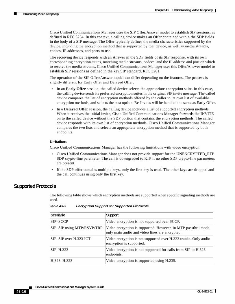
Supported Protocols
The following table shows which encryption methods are supported when specific signaling methods are used.
Table 43-3 Encryption Support for Supported Protocols
Scenario Support
SIP–SCCP Video encryption is not supported over SCCP.
SIP–SIP using MTP/RSVP/TRP Video encryption is supported. However, in MTP passthru mode only main audio and video lines are encrypted.
SIP–SIP over H.323 ICT Video encryption is not supported over H.323 trunks. Only audio encryption is supported.
SIP–H.323 Video encryption is not supported for calls from SIP to H.323 endpoints.
H.323–H.323 Video encryption is supported using H.235.

43-17Cisco Unified Communications Manager System Guide
OL-24923-01
Chapter 43 Understanding Video Telephony Introducing Video Telephony
Presentation Sharing with the Binary Floor Control ProtocolCisco Unified Communications Manager supports presentation sharing within an ongoing video conversation using the Binary Floor Control Protocol (BFCP).
Cisco Unified Communications Manager aids in the negotiation of the BFCP stream by relaying SIP messages between the two endpoints until a BFCP session can be established. This negotiation involves establishing a floor, which is a temporary permission to access shared resources. The BFCP stream is a point-to-point stream between the endpoints. Cisco Unified Communications Manager is never the target of the BFCP stream.
As an example of how presentation sharing with BFCP works, you could have an ongoing video conversation between two SIP video phones. User A decides to show User B a slide presentation that is saved on a laptop. User A attaches the laptop to a Cisco EX90 video phone and presses the Present button on the phone. This sends to the other phone a SIP INVITE message containing the SDP parameters for the creation of a BFCP stream. After the BFCP session is negotiated, an additional stream is added to the audio and video streams. The BFCP stream allows User B to see the desktop of User A’s laptop.
BFCP is supported only on SIP networks. The entire network, including all endpoints, intermediary devices and trunks, must be SIP. BFCP must be enabled on all SIP trunks and SIP lines.
Note BFCP is not supported with IME trunks, so BFCP should be disabled for SIP profiles that are used for IME trunks.
The following network diagram displays the network topology that is used for BFCP. The Cisco Unified Communications Manager clusters are involved only in forwarding SIP messages between the devices. After the endpoints negotiate BFCP, the BFCP stream itself is a point-to-point stream between the devices.
Figure 43-2 provides an example of a BFCP-capable network. The network is fully SIP capable. The Cisco Unified Communications Manager cluster sits in the middle and relays SIP signaling between the endpoints. The BFCP stream as well as the audio and video streams, are point-to-point between the endpoints.
Figure 43-2 Simple Video Network Using BFCP
2551
21
SIP
Cisco UnifiedCommunicationsManager Cluster
SIP Trunk
SIP VideoPhone
Audio stream
Main video streamSecond video stream
BFCP stream
Cisco UnifiedCommunicationsManager Cluster
SIP
SIP VideoPhone

43-18Cisco Unified Communications Manager System Guide
OL-24923-01
Chapter 43 Understanding Video Telephony Introducing Video Telephony
BFCP Configuration Tips
To enable BFCP in Cisco Unified Communications Manager, check the Allow Presentation Sharing using BFCP check box in the SIP Profile Configuration window. If the check box is unchecked, all BFCP offers will be rejected. By default, the check box is unchecked.
BFCP is supported only on full SIP networks. For presentation sharing to work, BFCP must be enabled for all SIP endpoints as well as all SIP lines and SIP trunks between the endpoints.
Figure 43-3 provides an example of a complex video network with multiple Cisco Unified Communications Manager clusters. BFCP must be enabled on all the trunks and lines connecting the devices. For this network, BFCP must be enabled on the four SIP trunks and two SIP lines that connect the endpoints.
Figure 43-3 Video Network with Multiple Cisco Unified Communications Manager Clusters
BFCP Limitations
Cisco Unified Communications Manager rejects the BFCP stream in the following scenarios:
• The Allow Presentation Sharing using BFCP check box on the SIP Profile page is unchecked for one of the SIP lines or trunks in the network.
• One endpoint offers BFCP, but the other does not.
• The SIP line or SIP trunk uses MTP, RSVP, Trusted Relay Point (TRP), or Transcoder. In these cases, BFCP is not supported.
• The stream is between a SIP, and non-SIP endpoint. BFCP is supported only for SIP endpoints.
Note BFCP is not supported when used between Cisco Unified Communications Manager and Cisco TelePresence MCU.
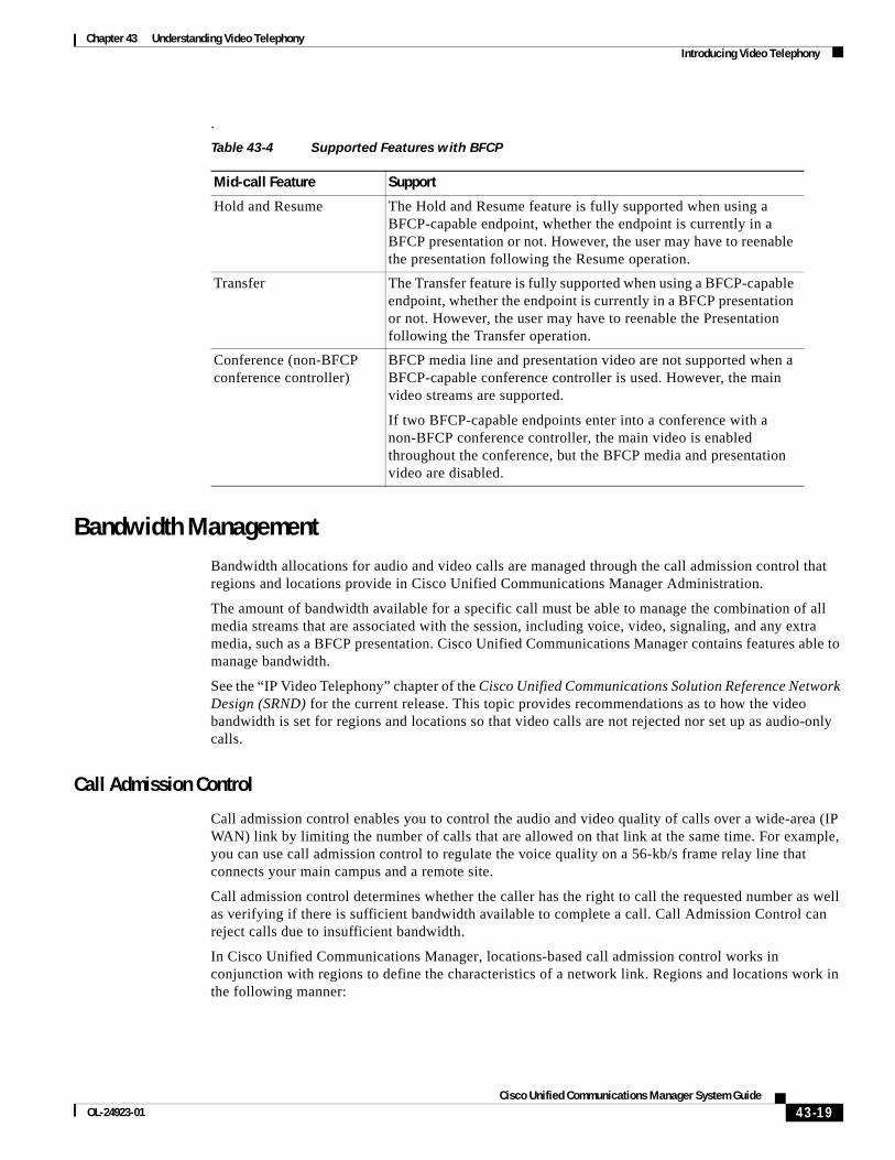
Supported Features with BFCP
The following table highlights how some of the common features are handled while a BFCP presentation is ongoing:
2551
22
SIP
Cisco UnifiedCommunicationsManager Cluster
SIP Trunk
SIP VideoPhone
Audio stream
Main video stream
Second video streamBFCP stream
Cisco UnifiedCommunicationsManager Cluster
SIP
SIP VideoPhone
Cisco UnifiedCommunicationsManager Cluster
SIP Trunk
43-19Cisco Unified Communications Manager System Guide
OL-24923-01
Chapter 43 Understanding Video Telephony Introducing Video Telephony
.
Bandwidth ManagementBandwidth allocations for audio and video calls are managed through the call admission control that regions and locations provide in Cisco Unified Communications Manager Administration.
The amount of bandwidth available for a specific call must be able to manage the combination of all media streams that are associated with the session, including voice, video, signaling, and any extra media, such as a BFCP presentation. Cisco Unified Communications Manager contains features able to manage bandwidth.
See the “IP Video Telephony” chapter of the Cisco Unified Communications Solution Reference Network Design (SRND) for the current release. This topic provides recommendations as to how the video bandwidth is set for regions and locations so that video calls are not rejected nor set up as audio-only calls.
Call Admission Control
Call admission control enables you to control the audio and video quality of calls over a wide-area (IP WAN) link by limiting the number of calls that are allowed on that link at the same time. For example, you can use call admission control to regulate the voice quality on a 56-kb/s frame relay line that connects your main campus and a remote site.
Call admission control determines whether the caller has the right to call the requested number as well as verifying if there is sufficient bandwidth available to complete a call. Call Admission Control can reject calls due to insufficient bandwidth.
In Cisco Unified Communications Manager, locations-based call admission control works in conjunction with regions to define the characteristics of a network link. Regions and locations work in the following manner:
Table 43-4 Supported Features with BFCP
Mid-call Feature Support
Hold and Resume The Hold and Resume feature is fully supported when using a BFCP-capable endpoint, whether the endpoint is currently in a BFCP presentation or not. However, the user may have to reenable the presentation following the Resume operation.
Transfer The Transfer feature is fully supported when using a BFCP-capable endpoint, whether the endpoint is currently in a BFCP presentation or not. However, the user may have to reenable the Presentation following the Transfer operation.
Conference (non-BFCP conference controller)
BFCP media line and presentation video are not supported when a BFCP-capable conference controller is used. However, the main video streams are supported.
If two BFCP-capable endpoints enter into a conference with a non-BFCP conference controller, the main video is enabled throughout the conference, but the BFCP media and presentation video are disabled.

43-20Cisco Unified Communications Manager System Guide
OL-24923-01
Chapter 43 Understanding Video Telephony Introducing Video Telephony
• Regions allow the bandwidth of video calls to be set. Regions define the maximum bit rate for each call, and hence, the type of codec, that is used on the link (and therefore, the amount of bandwidth that is used per call). For more information about regions, see Regions, page 5-10. For information on configuring Regions, see “Region Configuration” in the Cisco Unified Communications Manager Administration Guide.
• Locations define the amount of total bandwidth available for all calls on that link. When a call is made on a link the regional value for that call must be subtracted from the total bandwidth allowed for that link. For more information about locations, see Locations, page 8-4. For information on configuring Locations, see “Location Configuration” in the Cisco Unified Communications Manager Administration Guide.
For more information about call admission control, see Call Admission Control, page 8-1.
Session Level Bandwidth Modifiers
Cisco Unified Communications Manager provides location call admission control support for handling session level bandwidth modifiers. Session level bandwidth modifiers are communicated as part of the parameters in the SDP portion of the initial SIP signaling. These parameters indicate the maximum amount of bandwidth each endpoint will support for that type of call. These parameters are used, along with regions and locations settings, to set the bandwidth for each call.
During the initial call setup, both parties communicate to Cisco Unified Communications Manager their maximum allowed bandwidth for the call. Cisco Unified Communications Manager passes this communication to the other endpoint, but if the bandwidth that is specified by the endpoint is greater than the region setting, Cisco Unified Communications Manager replaces the value with the region bandwidth value.
Cisco Unified Communications Manager uses the following rules to determine the amount of bandwidth to allocate to a specific call:
• When Cisco Unified Communications Manager receives an Offer or Answer from an endpoint, it checks whether there is a session level bandwidth modifier in the SDP:
– If there is a session level bandwidth modifier, Cisco Unified Communications Manager retrieves the bandwidth value from the modifier. If there is more than one modifier type, it retrieves the modifier in the following order of preference: Transport Independent Application Specific (TIAS), Application Specific (AS), Conference Total (CT).
– If there is no session level bandwidth modifier, Cisco Unified Communications Manager retrieves the bandwidth value from the sum of the media level bandwidth modifiers. However, if there is BFCP or FECC in the call, it uses the TIAS value from the main media line.
• The allocated bandwidth is the maximum of what the two endpoints support up to the maximum value of the Region setting. The allocated bandwidth cannot exceed the region setting.
Cisco Unified Communications Manager uses the following logic when communicating with endpoints:
• When generating an Answer, Early Offer or Re-Invite Offer to an endpoint that contains more than one session level bandwidth modifier type (TIAS, AS, CT), Cisco Unified Communications Manager uses the same bandwidth value for each.
• When generating an answer, Cisco Unified Communications Manager uses the same session level bandwidth modifier type (TIAS, CT, AS) that was received in the initial offer
• For backward compatibility with older versions of Tandberg endpoints (such as MXP 1700), Cisco Unified Communications Manager suppresses the Session Level Bandwidth Modifier when a video call is put on hold and music on hold (MOH) is inserted.

43-21Cisco Unified Communications Manager System Guide
OL-24923-01
Chapter 43 Understanding Video Telephony Introducing Video Telephony
RSVP
RSVP supports SCCP and SIP video calls. Configure RSVP policy for call admission control by using the Location Configuration window in Cisco Unified Communications Manager Administration. For more information on the RSVP functionality, see the “Resource Reservation Protocol” section on page 9-1.
Alternate Routing
If an endpoint cannot obtain the bandwidth that it needs for a video call, a video call retries as an audio call for the default behavior. To use route/hunt lists or Automated Alternate Routing (AAR) groups to try different paths for such video calls, uncheck the Retry Video Call as Audio setting in the configuration settings for applicable gateways, trunks, and phones. See “Route List Configuration” and “Automated Alternate Routing Group Configuration” in the Cisco Unified Communications Manager Administration Guide for details.
DSCP Marking
Differentiated Services Code Point (DSCP) packet marking, which is used to specify the class of service for each packet, includes the following characteristics:
• Audio streams in audio-only calls default to EF.
• Video streams and associated audio streams in video calls default to AF41.
• You can change these defaults through the use of a service parameter. The following service parameter settings affect DSCP packet marking:
– DSCP for Audio Calls (for media [RTP] streams)
– DSCP for Video Calls (for media [RTP] streams)
– DSCP for Audio Calls when RSVP Fails
– DSCP for Video Calls when RSVP Fails
– DSCP for ICCP Protocol Links
Phone Configuration for Video CallsThe following setting for video-enabled devices affects video calls:
• Retry Video Call as Audio—By default, this check box remains checked. Thus, if an endpoint (phone, gateway, trunk) cannot obtain the bandwidth that it needs for a video call, call control retries the call as an audio call. This setting applies to the destination devices of video calls.
• Video Capabilities Enabled/disabled—This drop-down list box turns video capabilities on and off.
43-22Cisco Unified Communications Manager System Guide
OL-24923-01
Chapter 43 Understanding Video Telephony Introducing Video Telephony
Additional Configuration for Video CallsThe following configuration considerations also affect the ability to make video calls in Cisco Unified Communications Manager:
• Trunk interaction with the H.323 client
• Call routing considerations
• Resetting gateway timer parameters
Trunk Interaction with H.323 Client
Trunk interaction with the H.323 Client for video calls functions identically to interaction functions for audio calls. See the “Trunks and Gatekeepers in Cisco Unified Communications Manager” section on page 41-7.
Call Routing for Video Calls
Call routing for video calls functions identically to call routing for audio calls.
Gateway Timer Parameter
For some bonding calls through the H.323/H.320 gateway, the gateway requires a longer time to exchange the H.323 TCS message. If the time required is greater than the timer setting for several Cisco CallManager service parameters, Cisco Unified Communications Manager will drop the call.
If the default Cisco Unified Communications Manager gateway timer values appear to be too short, Cisco Unified Communications Manager drops the call before completion of the call connection. Cisco recommends increasing the following service parameter timers values to avoid call failure.
• H245TCSTimeout=25
• Media Exchange Interface CapabilityTimer=25
• Media Exchange Timer=25
Conference Control for Video ConferencingCisco Unified Communications Manager supports the following conference controls capabilities:
• Roster/Attendee List
• Drop Participant
• Terminate Conference
• Show Conference Chairperson/Controller
• Continuous Presence
Cisco Unified Communications Manager also supports the following video conference capabilities for Skinny Client Control Protocol phones:
• Display controls for video conferences. The Skinny Client Control Protocol phones can choose to use the continuous presence or voice-activated mode to view the video conference. When a mode is chosen, a message gets sent to the bridge to indicate which mode to use on the video channel. Switching between modes does not require renegotiation of media.

43-23Cisco Unified Communications Manager System Guide
OL-24923-01
Chapter 43 Understanding Video Telephony Introducing Video Telephony
• Display participant information such as the user name in the video stream. The system can use the participant information for other conferencing features such as roster.
Video and InteroperabilityCisco Unified Communications Manager 8.5 supports native or direct interoperability between Cisco video endpoints and 3rd party video endpoints such as Polycom. This means that Cisco Unified Communications Manager does not require a media gateway or conference bridge, such as Cisco Unified Video Conferencing (CUVC), for a simple point-to-point call between the supported endpoints.
Protocols and Deployments
Video and interoperability support the following protocols:
• SIP to SIP
• H323 to H323
• SIP to SIP Intercluster trunk (ICT) to SIP
• H323 to H323 ICT to H323
• SIP to H323 with or without ICT
For more information about limitations and special considerations of this features, see the “Limitations” section on page 43-24 and the Cisco Unified Communications Solution Reference Network Design (SRND).
Video and interoperability support the following deployments:
• High-Definition interoperability for point-to-point calls
• Locations-based call admission control (CAC) only
• Presentation sharing and secure interop between TelePresence and third-party endpoints that support the Telepresence Interop Protocol (TIP)
• Multipoint calls involving Cisco TelePresence System (CTS), Cisco Unified Communications Manager, and third-party endpoints use Media transcoding Engine (MXE) and Cisco Unified Video Conferencing (CUVA)
For more information about supported deployments, see the Cisco Unified Communications Solution Reference Network Design (SRND).
Cisco and Third-Party Endpoints Supported
Video and interoperability support the following endpoints:
• Cisco-certified third-party video endpoints
• Cisco E20 (Tandberg E20)
• Cisco Unified Clients Services Framework (CSF) based clients, such as Cisco Unified Communication interface for Microsoft Office Communicator (CUCiMOC) or CUCiConnect (for example, Cisco WebEx)
• Cisco Unified Video Advantage (CUVA)
• Cisco Unified Personal Communicator (CUPC)
• Cisco Unified IP Phone 7985

43-24Cisco Unified Communications Manager System Guide
OL-24923-01
Chapter 43 Understanding Video Telephony Video Telephony and Cisco Unified Serviceability
• Cisco Unified IP Phone 9951 and 9971
• Cisco Unified IP Phone 8961 (requires CUVA)
• MeetingPlace Conference bridges, such as MP Hardware Media Switch (HMS) or Software Media Switch (SMS)
To find a Cisco-certified third-party device, go the following URL:
http://developer.cisco.com/web/partner/search
Perform the following steps:
1. Sign in to the Cisco Developer Network (CDN) (if applicable)
2. From the CDN main window, click the Technology Partners tab.
3. Click the Partner Search tab.
4. In the search box, enter the name of a 3rd party company (within all technologies) (for example, Polycom).
5. When the 3rd party company information displays, click the applicable links for more information.
Third-party devices get configured in Cisco Unified Communications Manager Administration, Phone Configuration. See Third-Party SIP Endpoints, page 42-21 for the list of supported device types.
For licensing requirements, see Third-Party SIP Endpoints, page 42-21.
Limitations
The following limitations apply:
• Advanced presentation sharing and security interoperability is supported only between two TelePresence Interop Protocol (TIP) capable endpoints.
• H239 presentation sharing and H235 security are supported only between two H323 endpoints.
• For ensure optimal resolution between the two endpoints, the protocol on the endpoints and the trunk should be identical; for example, SIP point-to-point endpoints connected by a SIP trunk.
• Locations-based CAC only for interoperability with TelePresence
• Ad hoc and Meet-Me conferencing support CUVC and MeetingPlace software media servers. Because the conferencing bridges support SCCP and the endpoints support SIP or H323, resolution may be limited to standard definition.
• Cisco Intercompany Media Engine (IME) is not supported between Cisco Unified Communications Manager endpoints and Telepresence.
Video Telephony and Cisco Unified ServiceabilityCisco Unified Serviceability tracks video calls and conferences by updating performance monitoring counters, video bridge counters, and call detail records (CDRs).
43-25Cisco Unified Communications Manager System Guide
OL-24923-01
Chapter 43 Understanding Video Telephony Video Telephony and Cisco Unified Serviceability
Performance Monitoring CountersVideo telephony events cause updates to the following Cisco Unified Serviceability performance monitoring counters:
• Cisco Unified Communications Manager
– VideoCallsActive
– VideoCallsCompleted
– VideoOutOfResources
• Cisco H.323
– VideoCallsActive
– VideoCallsCompleted
• Cisco Locations
– VideoBandwidthAvailable
– VideoBandwidthMaximum
– VideoOutOfResources
– VideoCurrentAvailableBandwidth
• Cisco Gatekeeper
– VideoOutOfResources
• Cisco SIP
– VideoCallsCompleted
– VideoCallsActive
See the Cisco Unified Serviceability Administration Guide for details.
Video Bridge CountersVideo conference events cause updates to these Cisco video conference bridge performance monitoring counters:
• ConferencesActive
• ConferencesAvailable
• ConferencesCompleted
• ConferencesTotal
• OutOfConferences
• OutOfResources
• ResourceActive
• ResourceAvailable
• ResourceTotal
These counters also display in the Cisco Unified Communications Manager object with the VCB prefix.
See the Cisco Unified Serviceability Administration Guide for details.
43-26Cisco Unified Communications Manager System Guide
OL-24923-01
Chapter 43 Understanding Video Telephony Where to Find More Information
Call Detail RecordsVideo telephony events cause updates to Call Detail Records (CDRs) in Cisco Unified Serviceability. These CDRs include the following information:
• IP address and port for video channels
• Codec: H.261, H.263, H.264, Cisco VT Camera wideband video
• Call bandwidth
• Resolution: QCIF, CIF, SQCIF, 4CIF, 16CIF, or Custom Picture Format
Cisco Unified Communications Manager also stores CDRs for midcall video and supports the following call scenarios:
• Skinny Client Control Protocol to Skinny Client Control Protocol calls
• Skinny Client Control Protocol to Skinny Client Control Protocol calls across an intercluster trunk (ICT)
Note CDR gets added when video is added mid-call, but CDR entry does not get removed as part of midcall video removal (for example, Cisco Video Telephony Advantage gets turned off).
See the Cisco Unified Communications Manager CDR Analysis and Reporting Administration Guide for details.
Where to Find More InformationRelated Topics
• Video Telephony Configuration Checklist, page 43-2
• Introducing Video Telephony, page 43-4
• Video Calls, page 43-4
• Video Codecs, page 43-5
• Video Network, page 43-6
• H.323 Video, page 43-7
• H.239—Extended Video Channels in H.323 Call, page 43-9
• Skinny Client Control Protocol Video, page 43-13
• Skinny Client Control Protocol Video Bridging, page 43-13
• SIP Video, page 43-14
• Bandwidth Management, page 43-19
• Phone Configuration for Video Calls, page 43-21
• Additional Configuration for Video Calls, page 43-22
• Conference Control for Video Conferencing, page 43-22
• Video Telephony and Cisco Unified Serviceability, page 43-24
• “Call Admission Control”
• Region Configuration, Cisco Unified Communications Manager Administration Guide
43-27Cisco Unified Communications Manager System Guide
OL-24923-01
Chapter 43 Understanding Video Telephony Where to Find More Information
• Location Configuration, Cisco Unified Communications Manager Administration Guide
• Conference Bridge Configuration, Cisco Unified Communications Manager Administration Guide
• Media Resource Group Configuration, Cisco Unified Communications Manager Administration Guide
• Media Resource Group List Configuration, Cisco Unified Communications Manager Administration Guide
• Automated Alternate Routing Group Configuration, Cisco Unified Communications Manager Administration Guide
• Route List Configuration, Cisco Unified Communications Manager Administration Guide
• Gateway Configuration, Cisco Unified Communications Manager Administration Guide
• Cisco Unified IP Phone Configuration, Cisco Unified Communications Manager Administration Guide
• Trunk Configuration, Cisco Unified Communications Manager Administration Guide
Additional Cisco Documentation
• Cisco Unified IP Phone administration documentation and release notes (all models)
• Cisco Unified IP Phone user documentation and release notes (all models)
• Cisco Unified Serviceability Administration Guide
• Cisco Unified Videoconferencing 3511 MCU and Cisco Unified Videoconferencing 3540 MCU Module Administrator Guide

43-28Cisco Unified Communications Manager System Guide
OL-24923-01
Chapter 43 Understanding Video Telephony Where to Find More Information