Embed Size (px)
Citation preview

Liquids are accumulated and stored in tanks of various shapes and sizes throughout the chemical process indus-
tries (CPI). A small number of com-panies have made the design, fabrica-tion and erection of these vessels their specialty. Initially, however, it is the process engineer who sizes and speci-fies tanks according to a specific ap-plication’s needs. In order to develop a data sheet for tank specifications, it is important for a process engineer to have a basic understanding of tanks and the related requirements.
Tanks are used to store many kinds of liquids. The focus here is on hydro-carbons, which deserve particular care because of their flammable or combus-tible properties. Hydrocarbon liquids can be classified per Table 1 [1]. The National Fire Protection Association
(NFPA) has published several volumes on recommended practices for fire pro-tection, wherein guidelines pertaining to the storage of hydrocarbon liquids are included.
Tank classificationsAccording to the NFPA [2], atmo-spheric storage tanks are defined as those tanks that are designed to oper-ate at pressures between atmospheric and 6.9 kPa gage, as measured at the top of the tank. Such tanks are built in two basic designs — the cone-roof de-sign where the roof remains fixed, and the floating-roof design where the roof floats on top of the liquid and rises and falls with the liquid level.Fixed roof design. Fixed-roof tanks consist of a cylindrical shell with a permanently welded roof that can be flat, conical or dome-shaped. Such
tanks are used to store materials with a true vapor pressure of less than 10.3 kPa absolute [3]. External-floating roof design. In floating-roof storage tanks, the roof is made to rest on the stored liquid and is free to move with the level of the liquid. These tanks reduce evaporation losses and control breathing losses while fill-ing. They are preferred for storage of petroleum products with a true vapor pressure of 10.3 to 76.5 kPa absolute [3]. There are principally three differ-ent types of external floating roofs and an internal floating-roof tank. Figure 1 illustrates each of them.• The pan-type roof (Figure 1.a) is a
single-deck roof and has the follow-ing characteristics:
- Full contact with liquid surface - Has a deck, hence any leak through
the deck will cause it to sink
Environmental Manager
74 CHEMICAL ENGINEERING WWW.CHE.COM APRIL 2006
Understanding Atmospheric Storage Tanks
Several sources of information are available to help the engineer
specify storage tanks for particular applications.
A sound basis for understanding the various considerations
is given here
Environmental Manager
Siddhartha Mukherjee, Lurgi India Co. Ltd.
NOMENCLATURE
A wetted surface area of the tank, m2
C tank capacity, m3
F environmental factor L latent heat of vaporization of stored
liquid at relieving pressure and temperature, kJ/kg
M molecular weight of the stored liq-uid, kg/kmol
Qe tank emptying rate, m3/hr Qf tank filling rate, m3/hr T temperature of relieving vapor, °K Vcorr venting rate of free air corrected for
stored liquids other than hexane, std m3/hr
Vhex venting rate of free air for reference liquid, hexane, std m3/hr
Vf emergency venting rate, std m3/hr Vib inbreathing, std m3/hr Vob outbreathing, std m3/hr
TABLE 1. CLASSIFICATION OF LIQUIDSClassifi-cation
Type of Liquid
Characteristics
Class IA Liquid
Flammable Liquid
Liquids that have a flash point below 22.8°C, and boiling point below 37.8°C
Class IB Liquid
Flammable Liquid
Liquids that have a flash point below 22.8°C, and boiling point at or above 37.8°C
Class IC Liquid
Flammable Liquid
Liquids that have a flash point at or above 22.8°C but below 37.8°C
Class II Liquid
Combustible Liquid
Liquids that have a flash point above 37.8°C and below 60°C
Class IIIA Liquid
Combustible Liquid
Liquids that have a flash point at or above 60°C and below 93°C
Class IIIB Liquid
Combustible Liquid
Liquids that have a flash point at or above 93°C
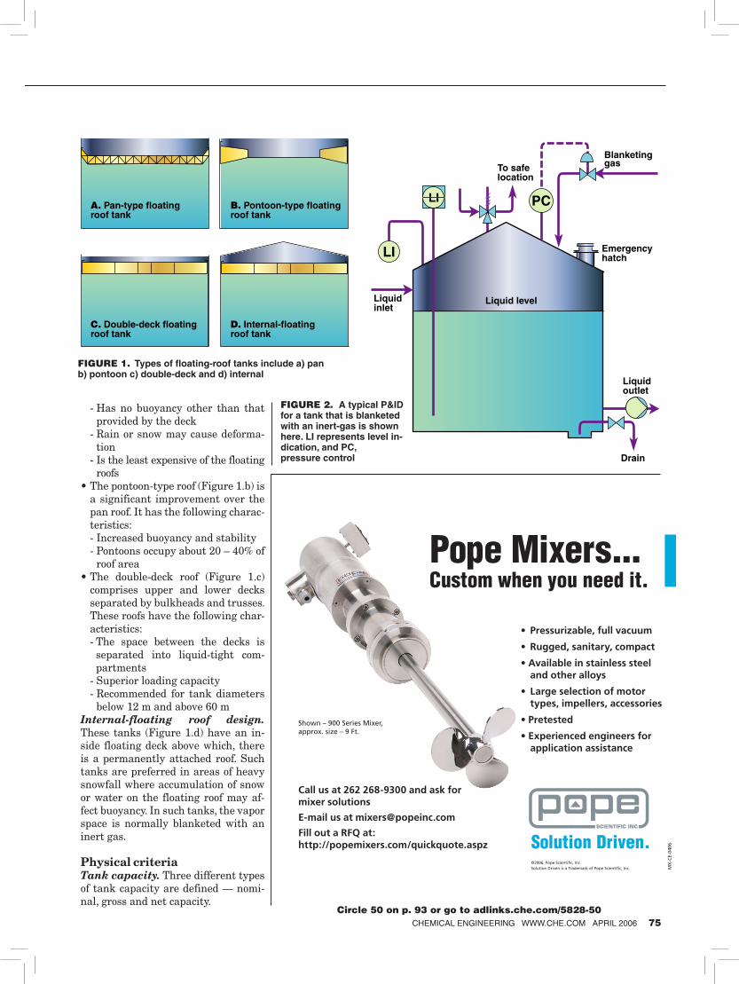
- Has no buoyancy other than that provided by the deck
- Rain or snow may cause deforma-tion
- Is the least expensive of the floating roofs
• The pontoon-type roof (Figure 1.b) is a significant improvement over the pan roof. It has the following charac-teristics:
- Increased buoyancy and stability - Pontoons occupy about 20 – 40% of
roof area• The double-deck roof (Figure 1.c)
comprises upper and lower decks separated by bulkheads and trusses. These roofs have the following char-acteristics:
- The space between the decks is separated into liquid-tight com-partments
- Superior loading capacity - Recommended for tank diameters
below 12 m and above 60 mInternal-floating roof design. These tanks (Figure 1.d) have an in-side floating deck above which, there is a permanently attached roof. Such tanks are preferred in areas of heavy snowfall where accumulation of snow or water on the floating roof may af-fect buoyancy. In such tanks, the vapor space is normally blanketed with an inert gas.
Physical criteriaTank capacity. Three different types of tank capacity are defined — nomi-nal, gross and net capacity.
CHEMICAL ENGINEERING WWW.CHE.COM APRIL 2006 75
������������������������������
����������������������������������
���������������������������������
������������������������������
FIGURE 1. Types of floating-roof tanks include a) pan b) pontoon c) double-deck and d) internal
���������������
����������������
������������
�������������
�����
������������
��������������
��
��
��
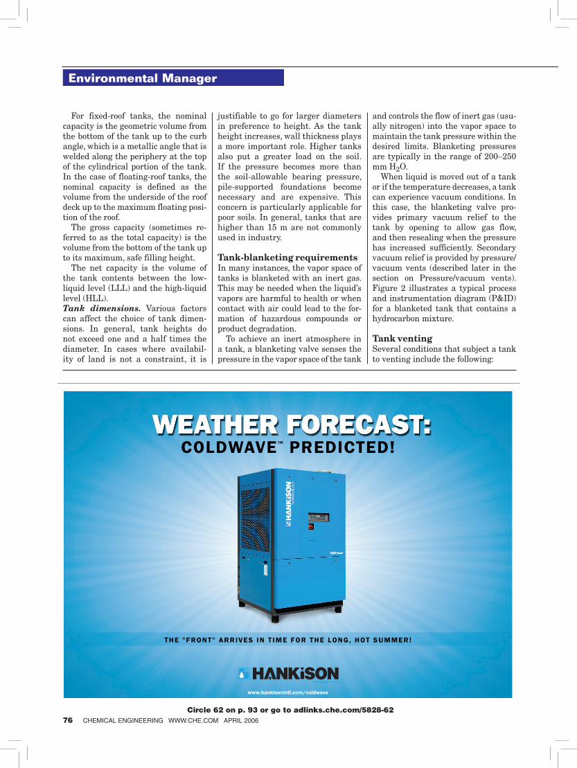
FIGURE 2. A typical P&ID for a tank that is blanketed with an inert-gas is shown here. LI represents level in-dication, and PC, pressure control
����������������������������������������������������������������������������������
�� ��������������������������
�� �������������������������
��������������������������������� ����������������
�� ���������������������������� �����������������������������
�����������
������������������������������ ����������������������
����������������������������������������������������
�������������������������������
���������������������������������������������������������
��
����
����
��������������������������������������
����������������������������������������������
Circle 50 on p. 93 or go to adlinks.che.com/5828-50
For fixed-roof tanks, the nominal capacity is the geometric volume from the bottom of the tank up to the curb angle, which is a metallic angle that is welded along the periphery at the top of the cylindrical portion of the tank. In the case of floating-roof tanks, the nominal capacity is defined as the volume from the underside of the roof deck up to the maximum floating posi-tion of the roof.
The gross capacity (sometimes re-ferred to as the total capacity) is the volume from the bottom of the tank up to its maximum, safe filling height.
The net capacity is the volume of the tank contents between the low-liquid level (LLL) and the high-liquid level (HLL). Tank dimensions. Various factors can affect the choice of tank dimen-sions. In general, tank heights do not exceed one and a half times the diameter. In cases where availabil-ity of land is not a constraint, it is
justifiable to go for larger diameters in preference to height. As the tank height increases, wall thickness plays a more important role. Higher tanks also put a greater load on the soil. If the pressure becomes more than the soil-allowable bearing pressure, pile-supported foundations become necessary and are expensive. This concern is particularly applicable for poor soils. In general, tanks that are higher than 15 m are not commonly used in industry.
Tank-blanketing requirementsIn many instances, the vapor space of tanks is blanketed with an inert gas. This may be needed when the liquid’s vapors are harmful to health or when contact with air could lead to the for-mation of hazardous compounds or product degradation.
To achieve an inert atmosphere in a tank, a blanketing valve senses the pressure in the vapor space of the tank
and controls the flow of inert gas (usu-ally nitrogen) into the vapor space to maintain the tank pressure within the desired limits. Blanketing pressures are typically in the range of 200–250 mm H2O.
When liquid is moved out of a tank or if the temperature decreases, a tank can experience vacuum conditions. In this case, the blanketing valve pro-vides primary vacuum relief to the tank by opening to allow gas flow, and then resealing when the pressure has increased sufficiently. Secondary vacuum relief is provided by pressure/vacuum vents (described later in the section on Pressure/vacuum vents). Figure 2 illustrates a typical process and instrumentation diagram (P&ID) for a blanketed tank that contains a hydrocarbon mixture.
Tank venting Several conditions that subject a tank to venting include the following:
Environmental Manager
76 CHEMICAL ENGINEERING WWW.CHE.COM APRIL 2006
COLDWAVETM PREDICTED!
www.hankisonintl.com/coldwave
THE "FRONT" ARRIVES IN T IME FOR THE LONG, HOT SUMMER!
ColdWaveAd_ChemicalEngineering-0406.qxp 3/17/2006 2:23 PM Page 1
Circle 62 on p. 93 or go to adlinks.che.com/5828-62

• Inbreathing due to liquid movement out of the tank
• Inbreathing due to contraction or condensation of vapors caused by a decrease in the atmospheric temper-ature (also called thermal inbreath-ing)
• Outbreathing due to liquid move-ment into the tank
• Outbreathing due to expansion or vaporization of vapors caused by an increase in the atmospheric tem-perature (also called thermal out-breathing)
• Outbreathing resulting from exter-nal fire
Inbreathing. According to the Ameri-can Petroleum Institute (API) [4], the venting capacity for maximum liquid movement out of a tank should be equivalent to 0.159 std m3/hr of air for each 0.159 m3/hr of the maximum emptying rate of liquids. This holds for liquids of any flash point. In other words, for an emptying rate of Qe m3/hr, the venting capacity should be Qe std m3/hr.
There are also requirements for thermal inbreathing. The API [4] fur-nishes these requirements as a func-tion of tank capacity in the form of tables. This information can also be expressed as an equation, wherein the thermal venting is expressed as a function of tank capacity.
The total venting capacity can be expressed as a sum of liquid move-ment and thermal inbreathing.
For tanks up to 3,500 m3 capacity:
Vib = Qe + 0.178C
For tanks larger than 3,500 m3 capac-ity:
Vib = Qe + 3.20C0.651
where Qe represents venting ca-pacity due to liquid movement and the second component represents that due to thermal inbreathing. C is the tank capacity. The total vent-ing requirement due to both liquid movement as well as thermal vent-ing is needed to ensure that the venting arrangement is designed for the worst-case scenario.Outbreathing. Whereas venting due to inbreathing is independent of flash point, the requirements for outbreathing differ with flash point. For liquids with a flash point above 37.8°C or a normal boiling point above 149°C, the re-quired venting capacity for maxi-mum liquid movement into a tank should be equivalent to 0.170 std
m3/hr of air for each 0.159 m3/hr of maximum filling rate. In other words, for a filling rate of Qf m3/hr, the vent-ing capacity should be 1.069Qf std m3/hr.
CHEMICAL ENGINEERING WWW.CHE.COM APRIL 2006 77
����������������������������
�����������������������
���������� ������ ������������������ ���� ������ ���������������������������������������
�����������������
��������� ������������������������� ��� �������������������������������������������������
����������������������������
������������������������������������
��������������� ���������������������
Circle 46 on p. 93 or go to adlinks.che.com/5828-46
����������
������
������������
���������������
������������
���������������
���������������
����������
�����
�������������
�������
���������������
�������������
����������������������������������
FIGURE 3. An external floating-roof tank may include these types of accessories
There are also requirements for thermal outbreathing. The total vent-ing capacity, expressed as a sum of liq-uid movement and thermal outbreath-ing can be expressed as follows.
For tanks up to 3,500 m3 capacity:
Vob = 1.069Qf + 0.107C
For tanks larger than 3,500 m3 capac-ity:
Vob = 1.069Qf + 1.92C0.651
For these liquids with a high flash point, the thermal outbreathing is roughly 60% of the thermal inbreathing requirement. The reason for this is that
the roof and shell temperatures cannot rise as rapidly as they can fall, for ex-ample, during a sudden rain shower.
Liquids with a lower flash point, below 37.8°C, or a normal boiling point below 149°C, have the following guide-lines. The requirement of venting capac-ity for maximum liquid movement into a tank should be equivalent to 0.340 std m3/hr of air for each 0.159 m3/hr of maximum filling rate. In other words, for a filling rate of Qf m3/hr, the venting capacity should be 2.138Qf std m3/hr. Of course, there are additional require-ments for thermal outbreathing. The total venting capacity, expressed as a sum of liquid movement and thermal outbreathing, can be expressed by the following equations.For tanks up to 3,500 m3 capacity:
Vob = 2.138Qf + 0.178C
and for tanks larger than 3,500 m3 capacity:
Vob = 2.138Qf + 3.20C0.651
Emergency Venting on Fire Expo-sure. When storage tanks are exposed to fire, the venting rate may exceed the inbreathing or outbreathing rate that results from a combination of thermal effects and liquid movement. For tanks subjected to fire exposure, the required venting capacities are given in Table 2 [4], for the reference liquid, hexane.
The environmental factor, F, is taken as 1.0 for bare-metal tanks. For insulated tanks, F varies between 0.025 and 0.30, depending upon the insulation conductance. The details are furnished in API 2000 [4].
The values in Table 2 are for hex-ane. For other liquids, the following corrected venting rate is applied.
Vcorr = (3098 · Vhex )/(M0.5 · L)
where M is the molecular weight of the stored liquid and L is the latent heat of vaporization of the stored liquid.
Emergency vents can be in the form of a gauge hatch that permits the cover to lift under high venting loads, or a manhole cover that lifts when exposed to high venting loads (Figure 2). Open vents. Tanks that store harm-less or non-toxic liquids, such as fire-water or service water, are vented to the atmosphere. These tanks operate
Your corporate knowledge is your most valuable asset. Now you can bring it back inside your organization.
PSE’s industry-unique Model-Based Innovation (MBI) service works with your experts to capture your knowledge and use it within your organization to generate value every day.
MBI combines high-accuracy gPROMS® Advanced Process Models with an innovative, well-tested methodology to enhance the effectiveness and efficiency of R&D in product and process innovation, design and operations.
MBI is helping our customers to accelerate innovation while carefully managing risk in areas such as reactor design, fuel cell development, crystallizer scale-up and new catalyst assessment.
The result: shorter time-to-market, improved designs of processes and products, enhancement of existing operations and lower R&D costs.
Model-Based Innovation. Helping build your knowledge.
Process Systems Enterprise
Tel: (DE) +49 221 16 79890
Tel: (J) +81 45 348 6330
Tel: (UK) +44 20 8563 0888
Tel: (US) +1 973 993 1850
Email: [email protected]
Web: www.psenterprise.com
Insource your expertiseBe different
Visit us at
ACHEMA Hall 9.1
Stand D41
Circle 48 on p. 93 or go to adlinks.che.com/5828-48
Environmental Manager
78 CHEMICAL ENGINEERING WWW.CHE.COM APRIL 2006
at atmospheric pressure and the vent-ing is called open venting. While being filled, the tank breathes out through the vent. When liquid is pumped out, the tank breathes in through the vent. To prevent rain or snow from entering, the vent pipe is usually provided with a weather hood, or alternatively, the pipe itself is shaped in the form of a goose neck.
According to API 2000 [4], open vents without flame arrestors may be used for venting under the following circumstances:• For storage of petroleum or petro-
leum products with a flash point of 37.8°C or above
• For tanks holding petroleum or pe-troleum products at a temperature below that of the flash point
• For storage of any product in tanks with a capacity of less than 9.46 m3
Flame arrestors need to be used with open venting of tanks that store petro-leum or petroleum products that have a flash point below 37.8°C.Pressure/vacuum vents. Pressure/vacuum vents are usually employed to protect blanketed tanks. In situations where the blanketing valve fails and gets stuck in the open position, the tank can be pressurized by the continuous inflow of inert gas. A pressure vent will open to protect the tank from rupture. Conversely, in situations where a tank is being emptied and the blanketing valve fails, the tank can reach vacuum conditions. A vacuum valve will open, thus protecting the tank from collapse.
Pressure and vacuum vents may be weight- or spring-loaded. Springs are generally used at set pressures above 7 kPa gage or at vacuum below –7 kPa gage. The pressure setting of the vent is kept slightly above the tank blanketing pressure but below the maximum pressure the tank can with-stand. Similarly, the vacuum setting is kept higher than the normal operating vacuum, but at a vacuum level that is below the maximum vacuum that the tank can withstand.
Because these vents are designed to remain closed until they must open in order to protect the tanks, another ad-vantage is that evaporation losses and fugitive emissions can be minimized by pressure and vacuum vents. This is achieved by preventing the release
TABLE 2. EMERGENCY VENTINGWetted surface area, m2
Design pres-sure, kPa gage
Emergency venting rate, std m3/hr
Area < 18 All Vf = 58,791(A·F/L)(T/M)0.5
18 < area < 93 All Vf = 208,888(A0.566F/L)(T/M)0.5
93 < area < 260 All Vf = 587,386(A0.338F/L)(T/M)0.5
Area > 260 > 6.9 Vf = 40,248(A0.82F/L)(T/M)0.5
Area > 260 < 6.9 Vf = 3,847,884(F/L)(T/M)0.5
Introducing Vapor Control Systems from VCI. The broad number of models in the product line provide everything from Pilot Operated Tank Blanketing to Weight Loaded Vent to Atmosphere systems. The units are available in aluminum, steel, stainless steel and fiberglass configurations for use in a wide variety of applications. The unique “modular” design allows the units to be quickly and economically upgraded in the future to provide greater control or meet stricter regulations.
The full line of VCI products are supported by a network of strategically located Service Centers that will feature factory trained staff specializing in vent calibration and repair. Contact VCI today for complete information.
Cashco, Inc.607 West 15th Street • P.O. Box 6 • Ellsworth, Kansas 67439Ph. (785) 472-4461 • Fax: (785) 472-3539www.valveconcepts.com
Vapor ControlNothing short of a revolution in
A Cashco, Inc. Company
VCI-105C.indd 1 12/27/05 9:13:46 AM
Circle 49 on p. 93 or go to adlinks.che.com/5828-49 CHEMICAL ENGINEERING WWW.CHE.COM APRIL 2006 79
of vapors that would otherwise occur during minor variations in tempera-ture, pressure or level.
InstrumentationProviding proper instrumentation in tanks is an important consideration, especially for large tanks that are subjected to frequent filling and emp-tying. The following guidelines may be useful for selecting tank instru-mentation.Level. At least two level instruments should be included — one with local indication and the other in the control room. In many cases, two level instru-ments with both local and remote in-dications are used. High and low level alarms are recommended.Temperature. Both local indication and remote indication with an alarm in case of high storage temperatures should be included.Pressure and flow. In blanketed tanks, it is advisable to install a flow and a pressure indicator with alarms to warn of problems in the blanketing gas line.
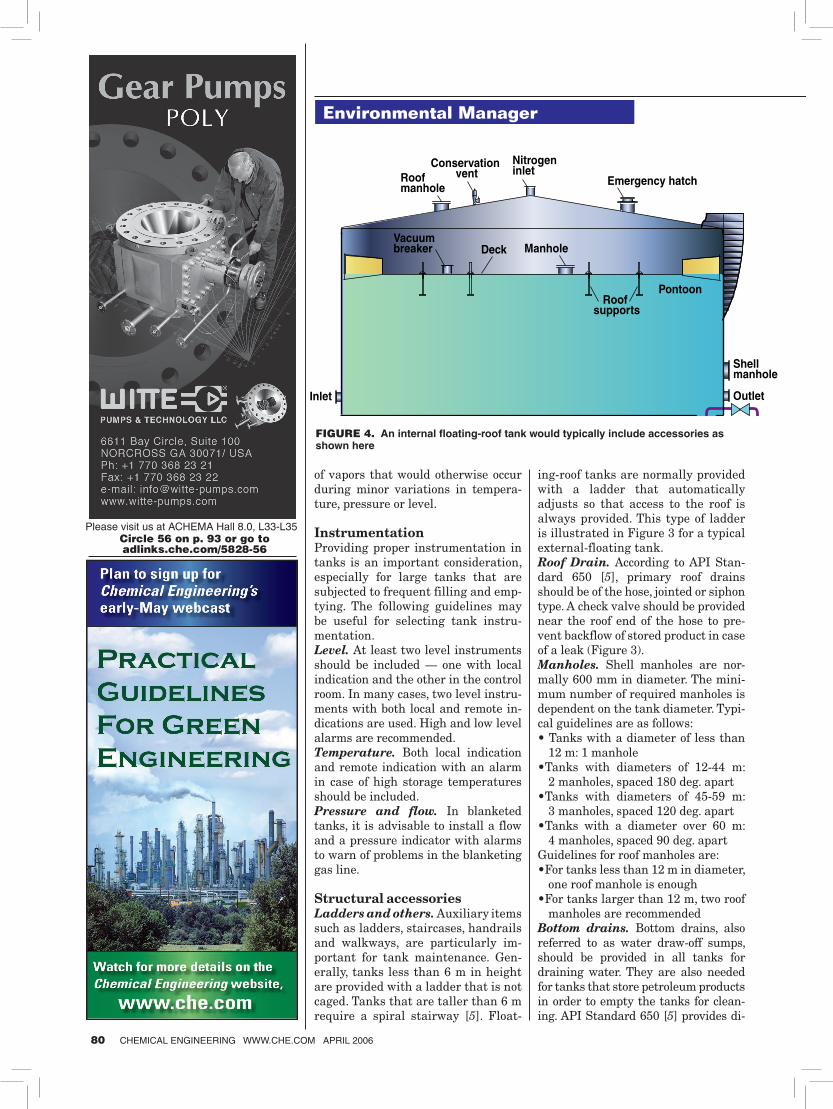
Structural accessoriesLadders and others. Auxiliary items such as ladders, staircases, handrails and walkways, are particularly im-portant for tank maintenance. Gen-erally, tanks less than 6 m in height are provided with a ladder that is not caged. Tanks that are taller than 6 m require a spiral stairway [5]. Float-
ing-roof tanks are normally provided with a ladder that automatically adjusts so that access to the roof is always provided. This type of ladder is illustrated in Figure 3 for a typical external-floating tank.Roof Drain. According to API Stan-dard 650 [5], primary roof drains should be of the hose, jointed or siphon type. A check valve should be provided near the roof end of the hose to pre-vent backflow of stored product in case of a leak (Figure 3). Manholes. Shell manholes are nor-mally 600 mm in diameter. The mini-mum number of required manholes is dependent on the tank diameter. Typi-cal guidelines are as follows:• Tanks with a diameter of less than
12 m: 1 manhole• Tanks with diameters of 12-44 m:
2 manholes, spaced 180 deg. apart• Tanks with diameters of 45-59 m:
3 manholes, spaced 120 deg. apart• Tanks with a diameter over 60 m:
4 manholes, spaced 90 deg. apartGuidelines for roof manholes are: •For tanks less than 12 m in diameter,
one roof manhole is enough•For tanks larger than 12 m, two roof
manholes are recommendedBottom drains. Bottom drains, also referred to as water draw-off sumps, should be provided in all tanks for draining water. They are also needed for tanks that store petroleum products in order to empty the tanks for clean-ing. API Standard 650 [5] provides di-
����������
������
������������
�����������
�����
�������������
������������
��������
��������������
���������������������������
�����������������
Environmental Manager
FIGURE 4. An internal floating-roof tank would typically include accessories as shown here
80 CHEMICAL ENGINEERING WWW.CHE.COM APRIL 2006
Circle 56 on p. 93 or go to adlinks.che.com/5828-56
Please visit us at ACHEMA Hall 8.0, L33-L35

mensional details of such drains. Figures 3 and 4 show typical struc-
tural accessories for both external and internal floating-roof tanks.
Spill control Facilities should be provided in the tankage area to prevent accidental
discharge of any Class I, II or IIIA liquid from endangering adjoining property. National Fire Codes [6] describe the requirements in detail. There are two types of facilities that can be provided.Remote impounding. In this case, the adjoining property is protected by
drainage of the discharge to a remote impounding area. The following guide-lines should be followed:• A slope of not less than 1% should be
provided for at least 15 m towards the impounding area
• The impounding area should have a capacity that can, at minimum, hold the contents of the largest tank that may drain into it
• Where it is not practical to have a 100% capacity remote impounding, partial remote impounding should be provided. The remainder of the impounding volume should be pro-vided by diking as discussed below
Impounding by diking. In cases where the adjoining property is protected by providing diked enclosures with roads all around the enclosure, the following guidelines should be followed:• The diked enclosure should be able
to contain the complete contents of the largest tank in the tank farm in case of any emergency. The capac-
������������������������������������������������������������������������������������������������������������
��������������
�� � � � � � � � � � � � � � � � � � � � � � � � � � � � � �
�������������������������������������
�����������������
����������
Circle 103 on p. 93 or go to adlinks.che.com/5828-103
Represented by:
Americas • Europe • India
Samhwa’s high quality helical and high shearstatic mixers are used worldwide for a varietyof applications, including food/pharmaceutical,polymerizaton, gases, liquid/gas, and powders,as well as general chemical applications.Housings can be built to ANSI/ASME, JIS, DIN,KS, or CE standards. Sizes range from 2 mm tomore than 2 meters in diameter. Special pilotplant units are also available with glass, hose,and acrylic housings.
Visit us in the JLS International booth(hall 4.1, stand L16) at Achema.
international Contact informationat www. jlsintl.com
Static Mixers @Competitive Prices
SAMHWAMixing Technology Co., Ltd.www.samhwamix.com
Circle 67 on p. 93 or go to adlinks.che.com/5828-67
CHEMICAL ENGINEERING WWW.CHE.COM APRIL 2006 81
TABLE 3. MINIMUM TANK SPACING1 Floating-roof tanks
Fixed or horizontal tanksClass I or II liquids
Class IIIA liquids
All Tanks not over 45 m in diameter:1/6 sum of adja-cent tank diam-eters but not less than 0.9 m
1/6 sum of adja-cent tank diam-eters but not less than 0.9 m
1/6 sum of adja-cent tank diam-eters but not less than 0.9 m
Tanks larger than 45 m in diameter:If remote im-pounding is pro-vided
1/6 sum of adja-cent tank diam-eters
1/4 sum of adja-cent tank diam-eters
1/6 sum of adja-cent tank diam-eters
If diking is pro-vided
1/4 sum of adja-cent tank diam-eters
1/3 sum of adja-cent tank diam-eters
1/4 sum of adja-cent tank diam-eters
1. Reprinted with permission from NFPA 30, Flammable and Combustible Liquids Code, Copy-right ©2003, National Fire Protection Association, Quincy, MA 02169. This reprinted material is not the complete and official position of the National Fire Protection Association on the referenced subject which is represented only by the standard in its entirety.
Circle 51 on p. 93 or go to adlinks.che.com/5828-51 CHEMICAL ENGINEERING WWW.CHE.COM APRIL 2006 83
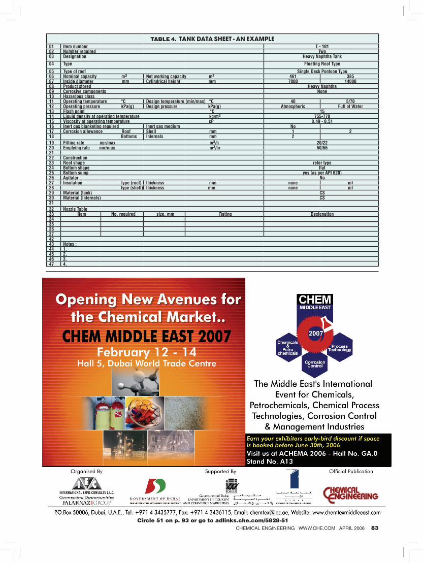
TABLE 4. TANK DATA SHEET - AN EXAMPLE01 Item number T - 10102 Number required Two03 Designation Heavy Naphtha Tank
04 Type Floating Roof Type
05 Type of roof Single Deck Pontoon Type06 Nominal capacity m3 Net working capacity m3 461 38507 Inside diameter mm Cylindrical height mm 7000 1400008 Product stored Heavy Naphtha09 Corrosive components None10 Hazardous class11 Operating temperature °C Design temperature (min/max) °C 40 5/7012 Operating pressure kPa(g) Design pressure kPa(g) Atmospheric Full of Water13 Flash point °C 1514 Liquid density at operating temperature kg/m3 755-77015 Viscosity at operating temperature cP 0.49 - 0.5116 Inert gas blanketing required Inert gas medium No17 Corrosion allowance Roof Shell mm 1 218 Bottoms Internals mm 219 Filling rate nor/max m3/h 20/2220 Emptying rate nor/max m3/hr 50/552122 Construction23 Roof shape refer type24 Bottom shape flat25 Bottom sump yes (as per API 620)26 Agitator No27 Insulation type (roof) thickness mm none nil28 type (shell) thickness mm none nil29 Material (tank) CS30 Material (internals) CS3132 Nozzle Table33 Item No. required size, mm Rating Designation343536 374243 Notes :44 1.45 2.46 3.47 4.
ity of the diked area should be cal-culated after deducting the volume of the tanks (other than the largest tank) below the height of the dike
• The height of the dike wall should be a minimum of 1 m and not more than 1.8 m from that of the internal grade
• The minimum distance between the tank shell and the base of the inte-
rior dike wall should be 1.5 m Layout and designNFPA provides detailed guidelines for layout and installation of above-ground storage tanks. Tanks storing Class I, II or IIIA stable liquids should be separated in accordance with Table 3 [6]. An exception to this is the case of crude-petroleum storage tanks
with individual capacities that do not exceed 476 m3 and are in production facilities in isolated locations. In such cases, the tanks need not be separated by more than 0.9 m.
After the process engineer has con-sidered the basic tank requirements, a tank data sheet can be generated. A typical tank data sheet, such as that shown in Table 4 (p. 83), illustrates all process features of a tank including the dimensions, type, capacity, oper-ating and design conditions, physical properties of the liquid stored, mate-rials of construction, corrosion allow-ances and insulation. In addition, it contains the details of all nozzles in the tank, their designations, sizes and ratings. A process sketch should also be included as part of the data sheet. The process engineer should also specify instrumentation needs, such as pressure, level and temperature sensors. ■
Edited by Dorothy Lozowski
things change...
the complete world of processingwww.powdershow.com/che
Conference: May 8 - 11 • 2006Expo: May 9 - 11 • 2006Donald E. Stephens Convention Center,Rosemont, IL
Sponsored by:
Co-locatedwith:
American Filtration & Separations Society Annual Conference
Bronze Sponsor: Web Sponsor:Produced by: Endorsed by:
Your success in life isn’t based on your ability to simply change. It isbased on your ability to change faster than your competition, customersand business. — Mark Sanborn
International Powder & Bulk Solids hasmade changes that will help you staycreative, innovative and competitive.
• Over 60% of the Conference Content is NEW.
• 20 NEW Conference faculty members.
• MyPowderShow, a NEW online eventplanning tool that will connect you withthe knowledge, people and productsyou want to see.
• Free Keynote address, The UltimateTurnaround: From Worst to First byGordon Bethune, former Chairman of the Board and CEO of ContinentalAirlines.
PBS_Ad_v2-half-che 2/8/06 9:01 AM Page 1
Circle 53 on p. 93 or go to adlinks.che.com/5828-53
References1. National Fire Protection Association, “Flam-
mable and Combustible Liquids Code,” Vol. 2, p. 30-10, Quincy, Mass., 1996
2. National Fire Protection Association, “Flam-mable and Combustible Liquids Code,” Vol. 2, p. 30-8, Quincy, Mass., 1996
3. Amrouche, Y., et.al., “General Rules for Aboveg-round Storage Tank Design and Operation,” Chem. Eng. Prog., pp. 54-58, December 2002.
4. American Petroleum Institute, “Venting Atmo-spheric and Low-Pressure Storage Tanks,” API Standard 2000, October 1992.
5. American Petroleum Institute. “Welded Steel Tanks for Oil Storage,” API Standard 650, 10th Edition, November 1998.
6. National Fire Protection Association, “Flam-mable and Combustible Liquids Code,” Vol. 2, p. 30-15, Quincy, Mass., 1996
AuthorSiddhartha Mukherjee is deputy general manager-pro-cess at Lurgi India Company Ltd. (A-30 Mohan Cooperative Industrial Estate, Mathura Road, New Delhi 110 044, India. Phone: +91-11-4259-5050; Fax: +91-11-4259-5051; Email: siddhartha_mukherjee@lurgi .de). For the past six years, he has been involved as a lead en-gineer in the design, precom-
missioning and commissioning of chemical and petrochemical plants in India and elsewhere. He has also been involved in inorganic and oleochem-istry while at Lurgi. Prior to this, Mukherjee worked as an environmental engineer with the Development Consultants Ltd. (Calcutta), doing various environmental assessment projects in-volving thermal power plants. Mukherjee earned his B.Tech. and Ph.D. chemical engineering de-grees from the Indian Institute of Technology, Kharagpur. He holds lifetime memberships in India’s Institution of Engineers and the Indian Institute of Chemical Engineers.
Environmental Manager
84 CHEMICAL ENGINEERING WWW.CHE.COM APRIL 2006