Embed Size (px)
Citation preview
Sign in (or register)English
Technical topics Evaluation software Community Events
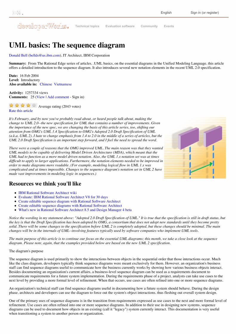
UML basics: The sequence diagramDonald Bell ([email protected]), IT Architect, IBM Corporation
Summary: From The Rational Edge series of articles, .UML basics, on the essential diagrams in the Unified Modeling Language, this articleoffers a detailed introduction to the sequence diagram. It also introduces several new notation elements in the recent UML 2.0 specification.
Date: 16 Feb 2004 Level: Introductory Also available in: Chinese Vietnamese
Activity: 1257334 views Comments: 25 (View | Add comment - Sign in)
Average rating (2043 votes)Rate this article
It's February, and by now you've probably read about, or heard people talk about, making thechange to UML 2.0--the new specification for UML that contains a number of improvements. Giventhe importance of the new spec, we are changing the basis of this article series, too, shifting ourattention from OMG's UML 1.4 Specification to OMG's Adopted 2.0 Draft Specification of UML(a.k.a. UML 2). I hate to change emphasis from 1.4 to 2.0 in the middle of a series of articles, but theUML 2.0 Draft Specification is an important step forward, and I feel the need to spread the word.
There were a couple of reasons that the OMG improved UML. The main reason was that they wantedUML models to be capable of delivering Model Driven Architecture (MDA), which meant that theUML had to function as a more model driven notation. Also, the UML 1.x notation set was at timesdifficult to apply to larger applications. Furthermore, the notation elements needed to be improved inorder to make diagrams more readable. (For example, modeling logical flow in UML 1.x wascomplicated and at times impossible. Changes to the sequence diagram's notation set in UML 2 havemade vast improvements in modeling logic in sequences.)
Resources we think you'll likeIBM Rational Software Architect wikiEvaluate: IBM Rational Software Architect V8 for 30 daysCreate editable sequence diagram with Rational Software ArchitectCreate editable sequence diagrams with Rational Software ArchitectWhat's new in Rational Software Architect 8.5 and Design Manager 4 beta
Notice the wording in my statement above: "Adopted 2.0 Draft Specification of UML." It is true that the specification is still in draft status, butthe key is that the Draft Specification has been adopted by OMG, a consortium that does not adopt new standards until they become prettysolid. There will be some changes to the specification before UML 2 is completely adopted, but these changes should be minimal. The mainchanges will be in the internals of UML--involving features typically used by software companies who implement UML tools.
The main purpose of this article is to continue our focus on the essential UML diagrams; this month, we take a close look at the sequencediagram. Please note, again, that the examples provided below are based on the new UML 2 specification.
The diagram's purpose
The sequence diagram is used primarily to show the interactions between objects in the sequential order that those interactions occur. Muchlike the class diagram, developers typically think sequence diagrams were meant exclusively for them. However, an organization's businessstaff can find sequence diagrams useful to communicate how the business currently works by showing how various business objects interact.Besides documenting an organization's current affairs, a business-level sequence diagram can be used as a requirements document tocommunicate requirements for a future system implementation. During the requirements phase of a project, analysts can take use cases to thenext level by providing a more formal level of refinement. When that occurs, use cases are often refined into one or more sequence diagrams.
An organization's technical staff can find sequence diagrams useful in documenting how a future system should behave. During the designphase, architects and developers can use the diagram to force out the system's object interactions, thus fleshing out overall system design.
One of the primary uses of sequence diagrams is in the transition from requirements expressed as use cases to the next and more formal level ofrefinement. Use cases are often refined into one or more sequence diagrams. In addition to their use in designing new systems, sequencediagrams can be used to document how objects in an existing (call it "legacy") system currently interact. This documentation is very usefulwhen transitioning a system to another person or organization.
The notation
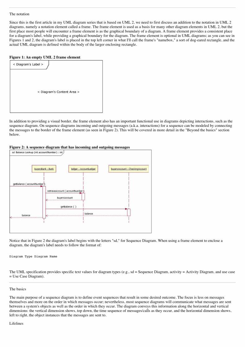
Since this is the first article in my UML diagram series that is based on UML 2, we need to first discuss an addition to the notation in UML 2diagrams, namely a notation element called a frame. The frame element is used as a basis for many other diagram elements in UML 2, but thefirst place most people will encounter a frame element is as the graphical boundary of a diagram. A frame element provides a consistent placefor a diagram's label, while providing a graphical boundary for the diagram. The frame element is optional in UML diagrams; as you can see inFigures 1 and 2, the diagram's label is placed in the top left corner in what I'll call the frame's "namebox," a sort of dog-eared rectangle, and theactual UML diagram is defined within the body of the larger enclosing rectangle.
Figure 1: An empty UML 2 frame element
In addition to providing a visual border, the frame element also has an important functional use in diagrams depicting interactions, such as thesequence diagram. On sequence diagrams incoming and outgoing messages (a.k.a. interactions) for a sequence can be modeled by connectingthe messages to the border of the frame element (as seen in Figure 2). This will be covered in more detail in the "Beyond the basics" sectionbelow.
Figure 2: A sequence diagram that has incoming and outgoing messages
Notice that in Figure 2 the diagram's label begins with the letters "sd," for Sequence Diagram. When using a frame element to enclose adiagram, the diagram's label needs to follow the format of:
Diagram Type Diagram Name
The UML specification provides specific text values for diagram types (e.g., sd = Sequence Diagram, activity = Activity Diagram, and use case= Use Case Diagram).
The basics
The main purpose of a sequence diagram is to define event sequences that result in some desired outcome. The focus is less on messagesthemselves and more on the order in which messages occur; nevertheless, most sequence diagrams will communicate what messages are sentbetween a system's objects as well as the order in which they occur. The diagram conveys this information along the horizontal and verticaldimensions: the vertical dimension shows, top down, the time sequence of messages/calls as they occur, and the horizontal dimension shows,left to right, the object instances that the messages are sent to.
Lifelines
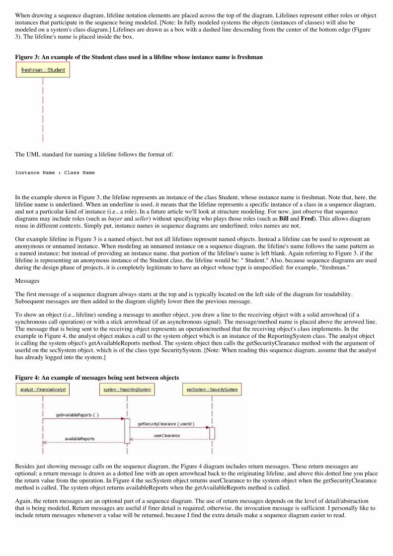
When drawing a sequence diagram, lifeline notation elements are placed across the top of the diagram. Lifelines represent either roles or objectinstances that participate in the sequence being modeled. [Note: In fully modeled systems the objects (instances of classes) will also bemodeled on a system's class diagram.] Lifelines are drawn as a box with a dashed line descending from the center of the bottom edge (Figure3). The lifeline's name is placed inside the box.
Figure 3: An example of the Student class used in a lifeline whose instance name is freshman
The UML standard for naming a lifeline follows the format of:
Instance Name : Class Name
In the example shown in Figure 3, the lifeline represents an instance of the class Student, whose instance name is freshman. Note that, here, thelifeline name is underlined. When an underline is used, it means that the lifeline represents a specific instance of a class in a sequence diagram,and not a particular kind of instance (i.e., a role). In a future article we'll look at structure modeling. For now, just observe that sequencediagrams may include roles (such as buyer and seller) without specifying who plays those roles (such as Bill and Fred). This allows diagramreuse in different contexts. Simply put, instance names in sequence diagrams are underlined; roles names are not.
Our example lifeline in Figure 3 is a named object, but not all lifelines represent named objects. Instead a lifeline can be used to represent ananonymous or unnamed instance. When modeling an unnamed instance on a sequence diagram, the lifeline's name follows the same pattern asa named instance; but instead of providing an instance name, that portion of the lifeline's name is left blank. Again referring to Figure 3, if thelifeline is representing an anonymous instance of the Student class, the lifeline would be: " Student." Also, because sequence diagrams are usedduring the design phase of projects, it is completely legitimate to have an object whose type is unspecified: for example, "freshman."
Messages
The first message of a sequence diagram always starts at the top and is typically located on the left side of the diagram for readability.Subsequent messages are then added to the diagram slightly lower then the previous message.
To show an object (i.e., lifeline) sending a message to another object, you draw a line to the receiving object with a solid arrowhead (if asynchronous call operation) or with a stick arrowhead (if an asynchronous signal). The message/method name is placed above the arrowed line.The message that is being sent to the receiving object represents an operation/method that the receiving object's class implements. In theexample in Figure 4, the analyst object makes a call to the system object which is an instance of the ReportingSystem class. The analyst objectis calling the system object's getAvailableReports method. The system object then calls the getSecurityClearance method with the argument ofuserId on the secSystem object, which is of the class type SecuritySystem. [Note: When reading this sequence diagram, assume that the analysthas already logged into the system.]
Figure 4: An example of messages being sent between objects
Besides just showing message calls on the sequence diagram, the Figure 4 diagram includes return messages. These return messages areoptional; a return message is drawn as a dotted line with an open arrowhead back to the originating lifeline, and above this dotted line you placethe return value from the operation. In Figure 4 the secSystem object returns userClearance to the system object when the getSecurityClearancemethod is called. The system object returns availableReports when the getAvailableReports method is called.
Again, the return messages are an optional part of a sequence diagram. The use of return messages depends on the level of detail/abstractionthat is being modeled. Return messages are useful if finer detail is required; otherwise, the invocation message is sufficient. I personally like toinclude return messages whenever a value will be returned, because I find the extra details make a sequence diagram easier to read.
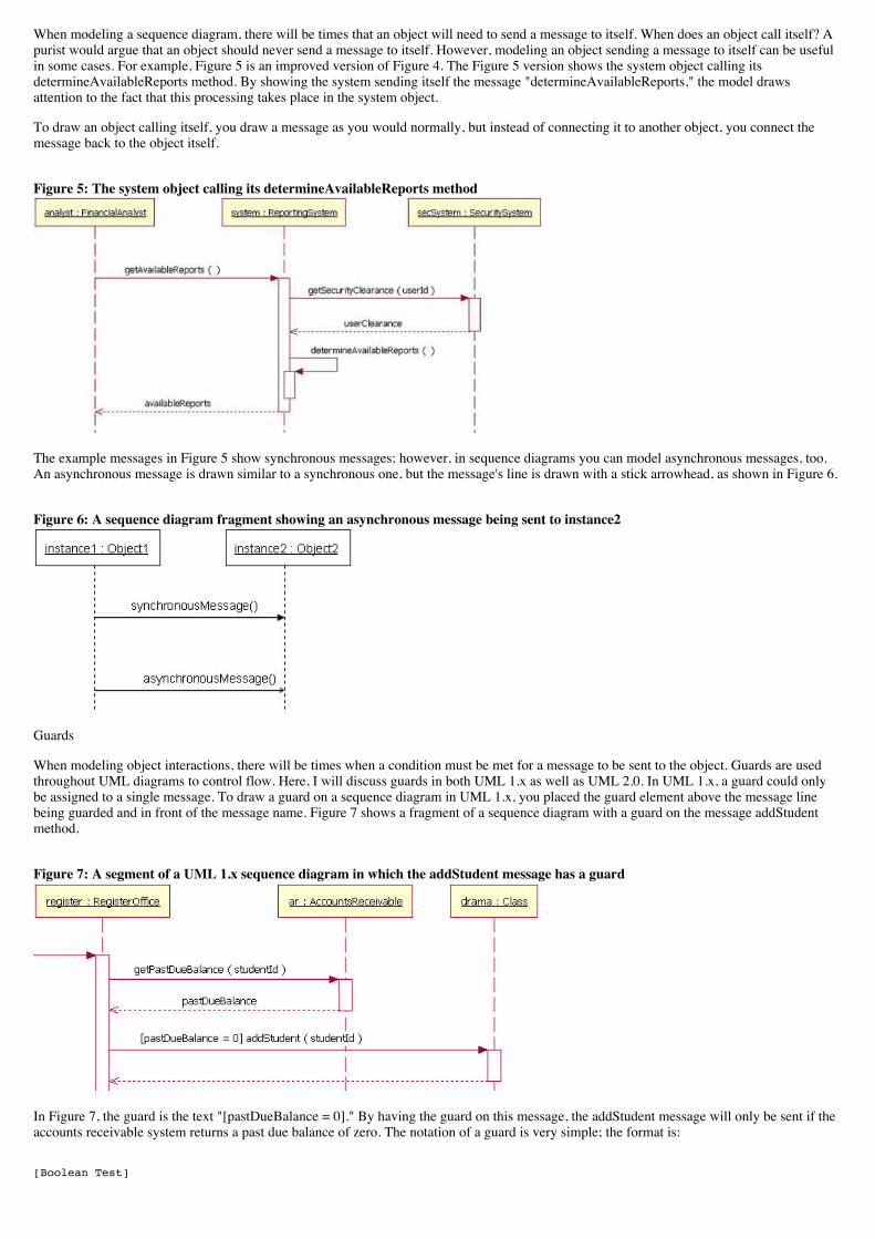
When modeling a sequence diagram, there will be times that an object will need to send a message to itself. When does an object call itself? Apurist would argue that an object should never send a message to itself. However, modeling an object sending a message to itself can be usefulin some cases. For example, Figure 5 is an improved version of Figure 4. The Figure 5 version shows the system object calling itsdetermineAvailableReports method. By showing the system sending itself the message "determineAvailableReports," the model drawsattention to the fact that this processing takes place in the system object.
To draw an object calling itself, you draw a message as you would normally, but instead of connecting it to another object, you connect themessage back to the object itself.
Figure 5: The system object calling its determineAvailableReports method
The example messages in Figure 5 show synchronous messages; however, in sequence diagrams you can model asynchronous messages, too.An asynchronous message is drawn similar to a synchronous one, but the message's line is drawn with a stick arrowhead, as shown in Figure 6.
Figure 6: A sequence diagram fragment showing an asynchronous message being sent to instance2
Guards
When modeling object interactions, there will be times when a condition must be met for a message to be sent to the object. Guards are usedthroughout UML diagrams to control flow. Here, I will discuss guards in both UML 1.x as well as UML 2.0. In UML 1.x, a guard could onlybe assigned to a single message. To draw a guard on a sequence diagram in UML 1.x, you placed the guard element above the message linebeing guarded and in front of the message name. Figure 7 shows a fragment of a sequence diagram with a guard on the message addStudentmethod.
Figure 7: A segment of a UML 1.x sequence diagram in which the addStudent message has a guard
In Figure 7, the guard is the text "[pastDueBalance = 0]." By having the guard on this message, the addStudent message will only be sent if theaccounts receivable system returns a past due balance of zero. The notation of a guard is very simple; the format is:
[Boolean Test]
For example,
[pastDueBalance = 0]
Combined fragments (alternatives, options, and loops)
In most sequence diagrams, however, the UML 1.x "in-line" guard is not sufficient to handle the logic required for a sequence being modeled.This lack of functionality was a problem in UML 1.x. UML 2 has addressed this problem by removing the "in-line" guard and adding anotation element called a Combined Fragment. A combined fragment is used to group sets of messages together to show conditional flow in asequence diagram. The UML 2 specification identifies 11 interaction types for combined fragments. Three of the eleven will be covered here in"The Basics" section, two more types will be covered in the "Beyond The Basics" section, and the remaining six I will leave to be covered inanother article. (Hey, this is an article, not a book. I want you to finish this piece in one day!)
Alternatives
Alternatives are used to designate a mutually exclusive choice between two or more message sequences. [Note: It is indeed possible for two ormore guard conditions attached to different alternative operands to be true at the same time, but at most only one operand will actually occur atrun time (which alternative "wins" in such cases is not defined by the UML standard).] Alternatives allow the modeling of the classic "if thenelse" logic (e.g., if I buy three items, then I get 20% off my purchase; else I get 10% off my purchase).
As you will notice in Figure 8, an alternative combination fragment element is drawn using a frame. The word "alt" is placed inside the frame'snamebox. The larger rectangle is then divided into what UML 2 calls operands. [Note: Although operands look a lot like lanes on a highway, Ispecifically did not call them lanes. Swim lanes are a UML notation used on activity diagrams. Please refer to The Rational Edge's earlierarticle about Activity Diagrams.] Operands are separated by a dashed line. Each operand is given a guard to test against, and this guard isplaced towards the top left section of the operand on top of a lifeline. [Note: Usually, the lifeline to which the guard is attached is the lifelinethat owns the variable that is included in the guard expression.] If an operand's guard equates to "true," then that operand is the operand tofollow.
Figure 8: A sequence diagram fragment that contains an alternative combination fragment
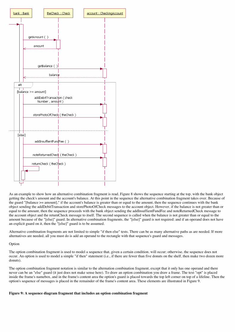
As an example to show how an alternative combination fragment is read, Figure 8 shows the sequence starting at the top, with the bank objectgetting the check's amount and the account's balance. At this point in the sequence the alternative combination fragment takes over. Because ofthe guard "[balance >= amount]," if the account's balance is greater than or equal to the amount, then the sequence continues with the bankobject sending the addDebitTransaction and storePhotoOfCheck messages to the account object. However, if the balance is not greater than orequal to the amount, then the sequence proceeds with the bank object sending the addInsuffientFundFee and noteReturnedCheck message tothe account object and the returnCheck message to itself. The second sequence is called when the balance is not greater than or equal to theamount because of the "[else]" guard. In alternative combination fragments, the "[else]" guard is not required; and if an operand does not havean explicit guard on it, then the "[else]" guard is to be assumed.
Alternative combination fragments are not limited to simple "if then else" tests. There can be as many alternative paths as are needed. If morealternatives are needed, all you must do is add an operand to the rectangle with that sequence's guard and messages.
Option
The option combination fragment is used to model a sequence that, given a certain condition, will occur; otherwise, the sequence does notoccur. An option is used to model a simple "if then" statement (i.e., if there are fewer than five donuts on the shelf, then make two dozen moredonuts).
The option combination fragment notation is similar to the alternation combination fragment, except that it only has one operand and therenever can be an "else" guard (it just does not make sense here). To draw an option combination you draw a frame. The text "opt" is placedinside the frame's namebox, and in the frame's content area the option's guard is placed towards the top left corner on top of a lifeline. Then theoption's sequence of messages is placed in the remainder of the frame's content area. These elements are illustrated in Figure 9.
Figure 9: A sequence diagram fragment that includes an option combination fragment
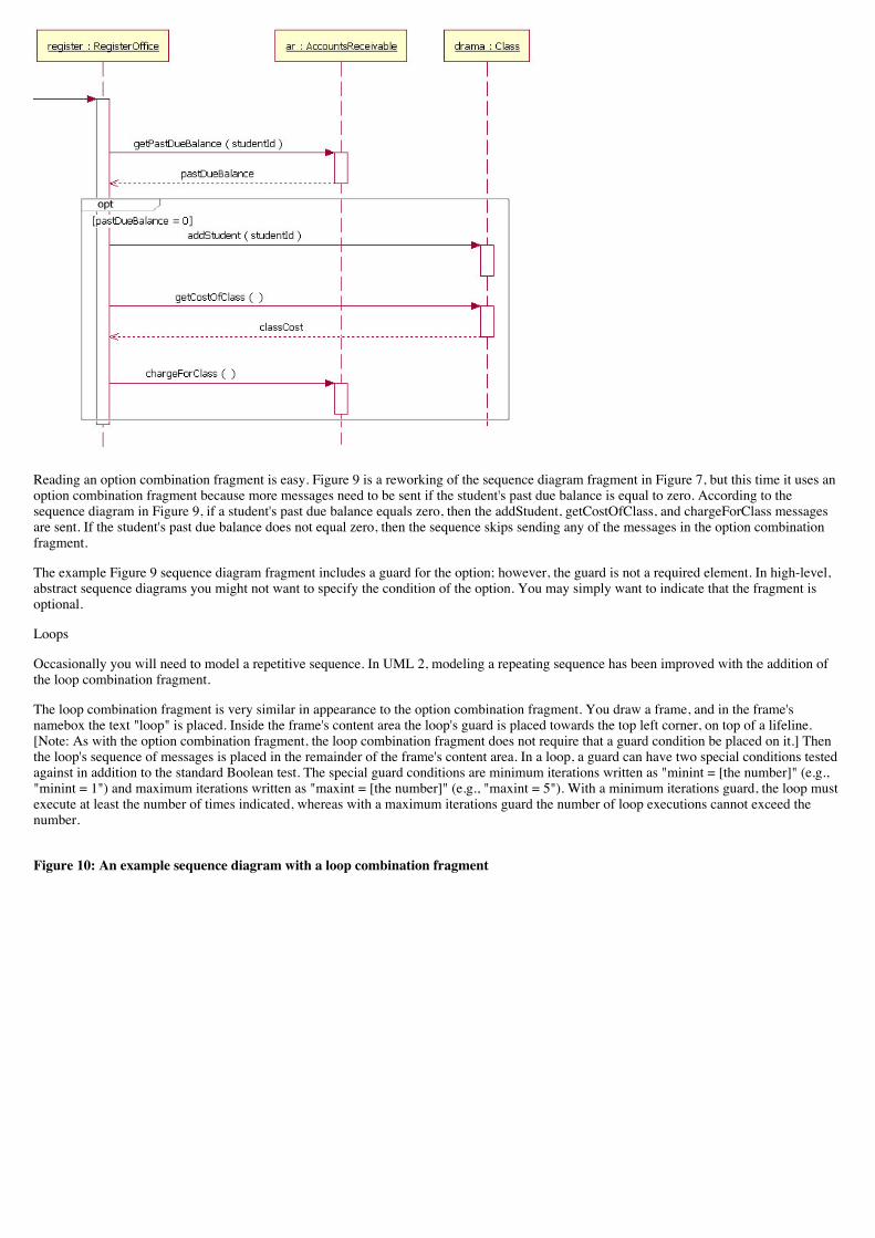
Reading an option combination fragment is easy. Figure 9 is a reworking of the sequence diagram fragment in Figure 7, but this time it uses anoption combination fragment because more messages need to be sent if the student's past due balance is equal to zero. According to thesequence diagram in Figure 9, if a student's past due balance equals zero, then the addStudent, getCostOfClass, and chargeForClass messagesare sent. If the student's past due balance does not equal zero, then the sequence skips sending any of the messages in the option combinationfragment.
The example Figure 9 sequence diagram fragment includes a guard for the option; however, the guard is not a required element. In high-level,abstract sequence diagrams you might not want to specify the condition of the option. You may simply want to indicate that the fragment isoptional.
Loops
Occasionally you will need to model a repetitive sequence. In UML 2, modeling a repeating sequence has been improved with the addition ofthe loop combination fragment.
The loop combination fragment is very similar in appearance to the option combination fragment. You draw a frame, and in the frame'snamebox the text "loop" is placed. Inside the frame's content area the loop's guard is placed towards the top left corner, on top of a lifeline.[Note: As with the option combination fragment, the loop combination fragment does not require that a guard condition be placed on it.] Thenthe loop's sequence of messages is placed in the remainder of the frame's content area. In a loop, a guard can have two special conditions testedagainst in addition to the standard Boolean test. The special guard conditions are minimum iterations written as "minint = [the number]" (e.g.,"minint = 1") and maximum iterations written as "maxint = [the number]" (e.g., "maxint = 5"). With a minimum iterations guard, the loop mustexecute at least the number of times indicated, whereas with a maximum iterations guard the number of loop executions cannot exceed thenumber.
Figure 10: An example sequence diagram with a loop combination fragment
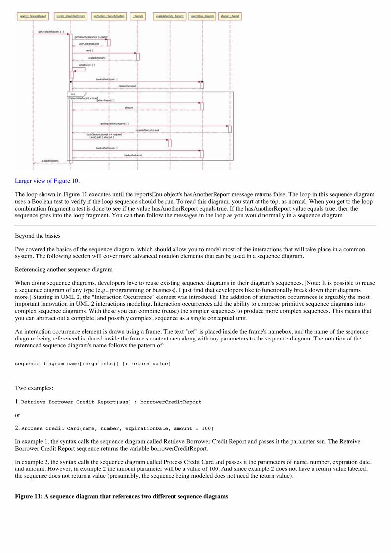
Larger view of Figure 10.
The loop shown in Figure 10 executes until the reportsEnu object's hasAnotherReport message returns false. The loop in this sequence diagramuses a Boolean test to verify if the loop sequence should be run. To read this diagram, you start at the top, as normal. When you get to the loopcombination fragment a test is done to see if the value hasAnotherReport equals true. If the hasAnotherReport value equals true, then thesequence goes into the loop fragment. You can then follow the messages in the loop as you would normally in a sequence diagram
Beyond the basics
I've covered the basics of the sequence diagram, which should allow you to model most of the interactions that will take place in a commonsystem. The following section will cover more advanced notation elements that can be used in a sequence diagram.
Referencing another sequence diagram
When doing sequence diagrams, developers love to reuse existing sequence diagrams in their diagram's sequences. [Note: It is possible to reusea sequence diagram of any type (e.g., programming or business). I just find that developers like to functionally break down their diagramsmore.] Starting in UML 2, the "Interaction Occurrence" element was introduced. The addition of interaction occurrences is arguably the mostimportant innovation in UML 2 interactions modeling. Interaction occurrences add the ability to compose primitive sequence diagrams intocomplex sequence diagrams. With these you can combine (reuse) the simpler sequences to produce more complex sequences. This means thatyou can abstract out a complete, and possibly complex, sequence as a single conceptual unit.
An interaction occurrence element is drawn using a frame. The text "ref" is placed inside the frame's namebox, and the name of the sequencediagram being referenced is placed inside the frame's content area along with any parameters to the sequence diagram. The notation of thereferenced sequence diagram's name follows the pattern of:
sequence diagram name[(arguments)] [: return value]
Two examples:
1. Retrieve Borrower Credit Report(ssn) : borrowerCreditReport
or
2. Process Credit Card(name, number, expirationDate, amount : 100)
In example 1, the syntax calls the sequence diagram called Retrieve Borrower Credit Report and passes it the parameter ssn. The RetreiveBorrower Credit Report sequence returns the variable borrowerCreditReport.
In example 2, the syntax calls the sequence diagram called Process Credit Card and passes it the parameters of name, number, expiration date,and amount. However, in example 2 the amount parameter will be a value of 100. And since example 2 does not have a return value labeled,the sequence does not return a value (presumably, the sequence being modeled does not need the return value).
Figure 11: A sequence diagram that references two different sequence diagrams
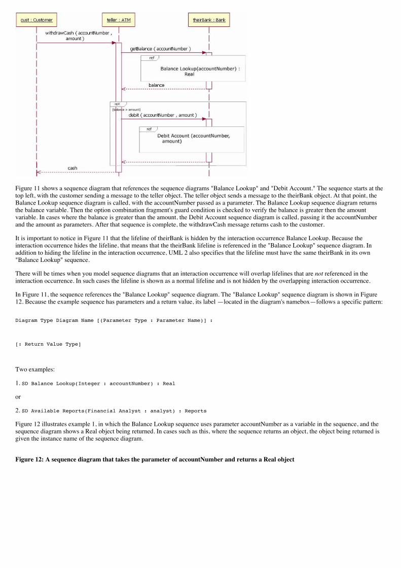
Figure 11 shows a sequence diagram that references the sequence diagrams "Balance Lookup" and "Debit Account." The sequence starts at thetop left, with the customer sending a message to the teller object. The teller object sends a message to the theirBank object. At that point, theBalance Lookup sequence diagram is called, with the accountNumber passed as a parameter. The Balance Lookup sequence diagram returnsthe balance variable. Then the option combination fragment's guard condition is checked to verify the balance is greater then the amountvariable. In cases where the balance is greater than the amount, the Debit Account sequence diagram is called, passing it the accountNumberand the amount as parameters. After that sequence is complete, the withdrawCash message returns cash to the customer.
It is important to notice in Figure 11 that the lifeline of theirBank is hidden by the interaction occurrence Balance Lookup. Because theinteraction occurrence hides the lifeline, that means that the theirBank lifeline is referenced in the "Balance Lookup" sequence diagram. Inaddition to hiding the lifeline in the interaction occurrence, UML 2 also specifies that the lifeline must have the same theirBank in its own"Balance Lookup" sequence.
There will be times when you model sequence diagrams that an interaction occurrence will overlap lifelines that are not referenced in theinteraction occurrence. In such cases the lifeline is shown as a normal lifeline and is not hidden by the overlapping interaction occurrence.
In Figure 11, the sequence references the "Balance Lookup" sequence diagram. The "Balance Lookup" sequence diagram is shown in Figure12. Because the example sequence has parameters and a return value, its label —located in the diagram's namebox—follows a specific pattern:
Diagram Type Diagram Name [(Parameter Type : Parameter Name)] :
[: Return Value Type]
Two examples:
1. SD Balance Lookup(Integer : accountNumber) : Real
or
2. SD Available Reports(Financial Analyst : analyst) : Reports
Figure 12 illustrates example 1, in which the Balance Lookup sequence uses parameter accountNumber as a variable in the sequence, and thesequence diagram shows a Real object being returned. In cases such as this, where the sequence returns an object, the object being returned isgiven the instance name of the sequence diagram.
Figure 12: A sequence diagram that takes the parameter of accountNumber and returns a Real object
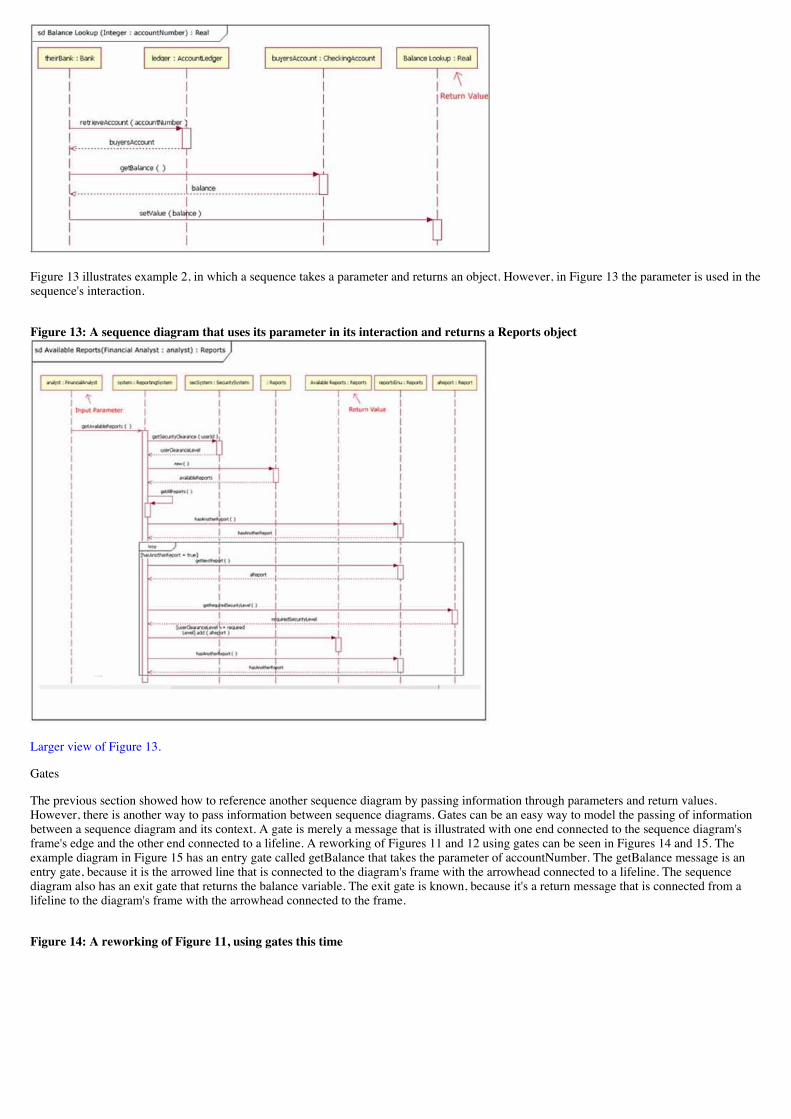
Figure 13 illustrates example 2, in which a sequence takes a parameter and returns an object. However, in Figure 13 the parameter is used in thesequence's interaction.
Figure 13: A sequence diagram that uses its parameter in its interaction and returns a Reports object
Larger view of Figure 13.
Gates
The previous section showed how to reference another sequence diagram by passing information through parameters and return values.However, there is another way to pass information between sequence diagrams. Gates can be an easy way to model the passing of informationbetween a sequence diagram and its context. A gate is merely a message that is illustrated with one end connected to the sequence diagram'sframe's edge and the other end connected to a lifeline. A reworking of Figures 11 and 12 using gates can be seen in Figures 14 and 15. Theexample diagram in Figure 15 has an entry gate called getBalance that takes the parameter of accountNumber. The getBalance message is anentry gate, because it is the arrowed line that is connected to the diagram's frame with the arrowhead connected to a lifeline. The sequencediagram also has an exit gate that returns the balance variable. The exit gate is known, because it's a return message that is connected from alifeline to the diagram's frame with the arrowhead connected to the frame.
Figure 14: A reworking of Figure 11, using gates this time
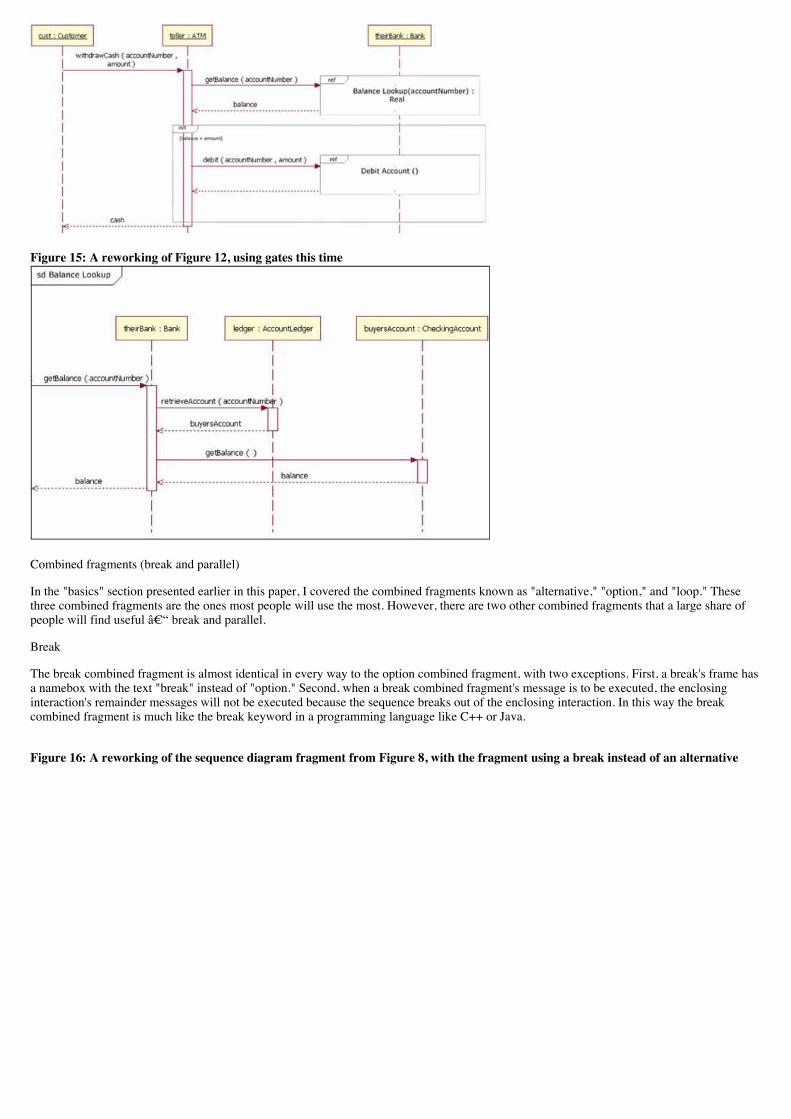
Figure 15: A reworking of Figure 12, using gates this time
Combined fragments (break and parallel)
In the "basics" section presented earlier in this paper, I covered the combined fragments known as "alternative," "option," and "loop." Thesethree combined fragments are the ones most people will use the most. However, there are two other combined fragments that a large share ofpeople will find useful – break and parallel.
Break
The break combined fragment is almost identical in every way to the option combined fragment, with two exceptions. First, a break's frame hasa namebox with the text "break" instead of "option." Second, when a break combined fragment's message is to be executed, the enclosinginteraction's remainder messages will not be executed because the sequence breaks out of the enclosing interaction. In this way the breakcombined fragment is much like the break keyword in a programming language like C++ or Java.
Figure 16: A reworking of the sequence diagram fragment from Figure 8, with the fragment using a break instead of an alternative
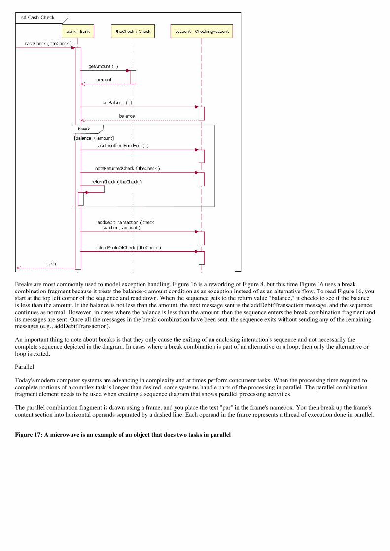
Breaks are most commonly used to model exception handling. Figure 16 is a reworking of Figure 8, but this time Figure 16 uses a breakcombination fragment because it treats the balance < amount condition as an exception instead of as an alternative flow. To read Figure 16, youstart at the top left corner of the sequence and read down. When the sequence gets to the return value "balance," it checks to see if the balanceis less than the amount. If the balance is not less than the amount, the next message sent is the addDebitTransaction message, and the sequencecontinues as normal. However, in cases where the balance is less than the amount, then the sequence enters the break combination fragment andits messages are sent. Once all the messages in the break combination have been sent, the sequence exits without sending any of the remainingmessages (e.g., addDebitTransaction).
An important thing to note about breaks is that they only cause the exiting of an enclosing interaction's sequence and not necessarily thecomplete sequence depicted in the diagram. In cases where a break combination is part of an alternative or a loop, then only the alternative orloop is exited.
Parallel
Today's modern computer systems are advancing in complexity and at times perform concurrent tasks. When the processing time required tocomplete portions of a complex task is longer than desired, some systems handle parts of the processing in parallel. The parallel combinationfragment element needs to be used when creating a sequence diagram that shows parallel processing activities.
The parallel combination fragment is drawn using a frame, and you place the text "par" in the frame's namebox. You then break up the frame'scontent section into horizontal operands separated by a dashed line. Each operand in the frame represents a thread of execution done in parallel.
Figure 17: A microwave is an example of an object that does two tasks in parallel
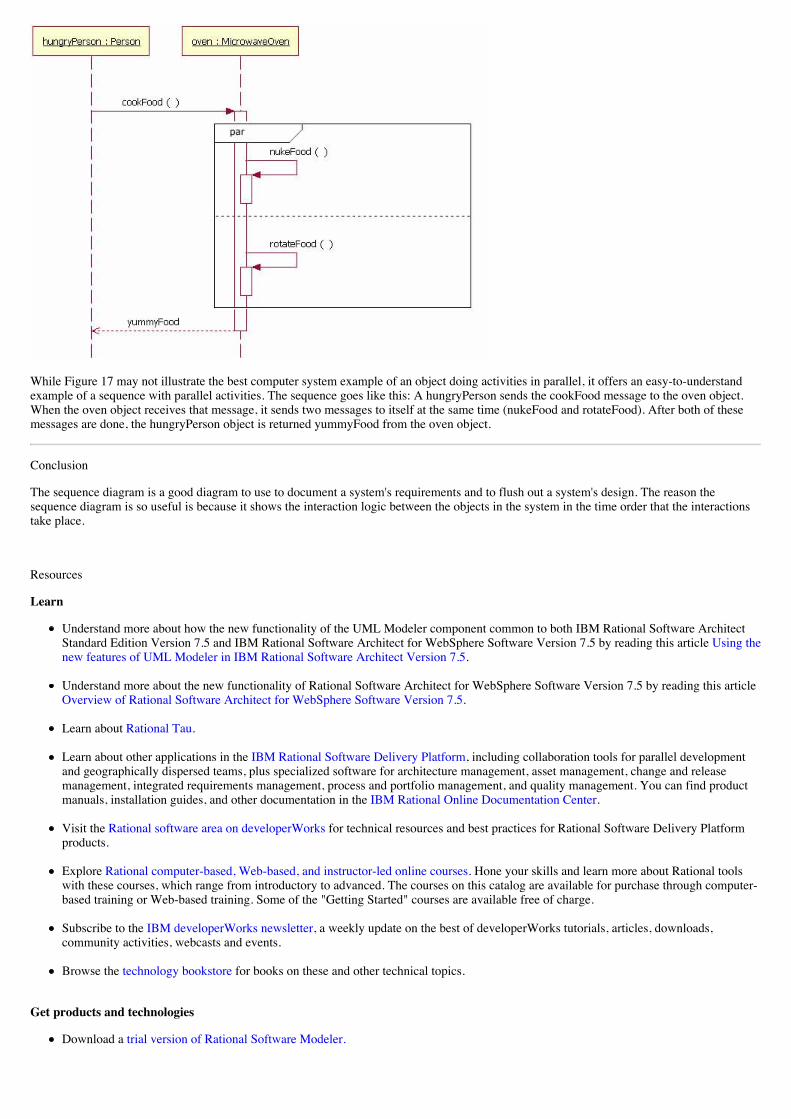
While Figure 17 may not illustrate the best computer system example of an object doing activities in parallel, it offers an easy-to-understandexample of a sequence with parallel activities. The sequence goes like this: A hungryPerson sends the cookFood message to the oven object.When the oven object receives that message, it sends two messages to itself at the same time (nukeFood and rotateFood). After both of thesemessages are done, the hungryPerson object is returned yummyFood from the oven object.
Conclusion
The sequence diagram is a good diagram to use to document a system's requirements and to flush out a system's design. The reason thesequence diagram is so useful is because it shows the interaction logic between the objects in the system in the time order that the interactionstake place.
Resources
Learn
Understand more about how the new functionality of the UML Modeler component common to both IBM Rational Software ArchitectStandard Edition Version 7.5 and IBM Rational Software Architect for WebSphere Software Version 7.5 by reading this article Using thenew features of UML Modeler in IBM Rational Software Architect Version 7.5.
Understand more about the new functionality of Rational Software Architect for WebSphere Software Version 7.5 by reading this articleOverview of Rational Software Architect for WebSphere Software Version 7.5.
Learn about Rational Tau.
Learn about other applications in the IBM Rational Software Delivery Platform, including collaboration tools for parallel developmentand geographically dispersed teams, plus specialized software for architecture management, asset management, change and releasemanagement, integrated requirements management, process and portfolio management, and quality management. You can find productmanuals, installation guides, and other documentation in the IBM Rational Online Documentation Center.
Visit the Rational software area on developerWorks for technical resources and best practices for Rational Software Delivery Platformproducts.
Explore Rational computer-based, Web-based, and instructor-led online courses. Hone your skills and learn more about Rational toolswith these courses, which range from introductory to advanced. The courses on this catalog are available for purchase through computer-based training or Web-based training. Some of the "Getting Started" courses are available free of charge.
Subscribe to the IBM developerWorks newsletter, a weekly update on the best of developerWorks tutorials, articles, downloads,community activities, webcasts and events.
Browse the technology bookstore for books on these and other technical topics.
Get products and technologies
Download a trial version of Rational Software Modeler.
Download a trial version of Rational Software Architect standard edition.
Download Rational Software Architect for Websphere Software.
Download Other IBM product evaluation versions and get your hands on application development tools and middleware products fromDB2®, Lotus®, Rational®, Tivoli®, and WebSphere®.
Discuss
Check out developerWorks blogs and get involved in the developerWorks community.
Join the Development Tools forum on developerWorks to discuss Rational Application Developer, Rational Software Architect, andRational Software Modeler.
Join the Rational Tau forum on developerWorks.
About the author
Donald Bell is an IT architect for IBM Rational software, where he works with clients to define and adopt effective software delivery practicesand tools.
Close [x]
developerWorks: Sign inIBM ID:Need an IBM ID?Forgot your IBM ID?
Password:Forgot your password?Change your password
Keep me signed in.
By clicking Submit, you agree to the developerWorks terms of use.
Submit Cancel
The first time you sign into developerWorks, a profile is created for you. Select information in your developerWorks profile is displayed tothe public, but you may edit the information at any time. Your first name, last name (unless you choose to hide them), and display namewill accompany the content that you post.
All information submitted is secure.
Close [x]
Choose your display nameThe first time you sign in to developerWorks, a profile is created for you, so you need to choose a display name. Your display nameaccompanies the content you post on developerWorks.
Please choose a display name between 3-31 characters. Your display name must be unique in the developerWorks community and shouldnot be your email address for privacy reasons.
Display name: (Must be between 3 – 31 characters.)
By clicking Submit, you agree to the developerWorks terms of use.
Submit Cancel
All information submitted is secure.
Average rating (2043 votes)
1 star 1 star2 stars 2 stars3 stars 3 stars4 stars 4 stars5 stars 5 stars
Submit
Add comment:
Sign in or register to leave a comment.
Note: HTML elements are not supported within comments.
Notify me when a comment is added1000 characters left
Post
Total comments (25) Show: Most recent comments
Very comprehensive material. Thanks you.
Posted by AlexanderMan on 09 July 2012
Report abuse
awesome article, with great fundamentalsvery helpful.thank you so much for such a beautiful article
Posted by mailforvicky on 16 April 2012
Report abuse
Excellent article. Thanks a lot!
Posted by Avik1982 on 17 January 2012
Report abuse
Very interesting to read, I am now a master of UML Sequence Diagram modeller. :o)
Posted by huahsin68 on 01 January 2012
Report abuse
Good article; nicely articulated! I've one doubt (though) on following statement. (Description on Lifeline)
"When an underline is used, it means that the lifeline represents a specific instance of a class in a sequence diagram, and not a particular kind ofinstance (i.e., a role). In a future article we'll look at structure modeling. For now, just observe that sequence diagrams may include roles (suchas buyer and seller) without specifying who plays those roles (such as Bill and Fred). This allows diagram reuse in different contexts. Simplyput, instance names in sequence diagrams are underlined; roles names are not."
Refer to Figure12, Figure13 and even Figure15. I wondered why these lifelines were NOT underlined. I assume above theory doesn't applyhere. Was it a typo or intentional? If intentional, can you clarify? This question is open to community as well. Any one who knows the answerplease respond.
CheersAbhilesh

Print this page Share this page Follow developerWorks
About
Help
Contact us
Submit content
Feeds and apps
Newsletters
Report abuse
Terms of use
IBM privacy
IBM accessibility
Faculty
Students
Business Partners
Posted by Abhilesh on 18 December 2011
Report abuse