Embed Size (px)
Citation preview

For more information: http://www.packtpub.com/UML/book
UML 2.0 in Action A Project-Based Tutorial
Patrick Grässle Henriette Baumann Philippe Baumann
Chapter 2 "Basic Principles and Background"
In this package, you will find: • A biography of the authors of the book
• A preview chapter from the book, Chapter 2 "Basic Principles and Background"
• A synopsis of the book’s content
• Information on where to buy this book
About the Authors
Patrick Grässle is the co-founder and board member of KnowGravity Inc. (www.knowgravity.com) in Zürich, a leading supplier of MDA and Business Rules know-how. Patrick studied Informatics and Economics at the University of Zürich. In 1986, he built his first model of an IT system using structured analysis and has not stopped modelling since then. He has applied UML in many projects. He used and consulted structured and object-oriented methods for system specification. In the nineties, he helped develop the first localized UML trainings in Switzerland.
The UML-based 'Model Driven Architecture' and the 'Business Rules Approach' absorb his main interest nowadays, but he is still doing UML training and consulting. Patrick can be reached at [email protected].
Henriette Baumann is the co-founder and board member of integratio GmbH (www.integratio.com), based in Zurich. Henriette studied Informatics and Economics and was involved in software development and engineering since the mid-eighties, particularly with the transformation of business requirements in software systems. In 1998, she started with UML business modeling and has used UML in several projects. Today her main focus is on project management and consulting for business analysis, business requirements engineering, and business specifications based on UML, especially for financial service companies.
Henriette can be reached at [email protected].
Philippe Baumann is co-founder and member of the board of integratio GmbH (www.integratio.com), based in Zurich.

Philippe studied Informatics at the University of Hagen (D) and was involved in software development and application integration since the mid-eighties. In 1998, he started with UML, and its usage in system integration and electronic data interchange between companies.
Today he is the project manager and consultant for technical aspects and implementation of software integration using UML. He is also active in the field of implementation and integration of Open Source business software such as ERP and CRM.
Philippe can be reached at [email protected].
UML 2.0 in Action: A Project-Based Tutorial, by Packt Publishing 5
2 Basic Principles and
Background
Much of what will be explained in the next few chapters is based on a few fundamental concepts. These have been summarized in this chapter.
2.1 Introduction to the Case Study For our case study we have chosen an airport—the UML Airport. Anyone who has ever been on a flight will have no problems understanding our example.
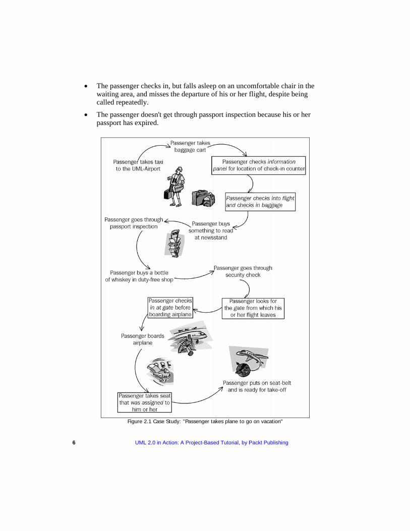
We will restrict our example to those areas of the airport that passengers are in contact with during departure, meaning we will take a closer look at passenger check-in and boarding. Figure 2.1 illustrates how passenger services can be distinguished from other areas of the airport. It shows the various stages that passengers go through until they are seated in the airplane, buckled up, and the plane is ready to take off. Not all stages passengers go through are related to passenger services. The stages that belong to passenger services are framed and printed in italic font.
A sequence of steps like this is called a scenario. However, the depicted scenario is only one of many possible scenarios. The following exceptions are possible for passenger check-in and boarding:
• The passenger only has carry-on luggage.
• The passenger doesn't buy anything at the newsstand.
• The passenger is running late and now has to check in as quickly as possible.
• The passenger loses his or her boarding pass.
• The passenger arrived by plane and merely has to change planes, meaning that he or she doesn't leave the transit area.
• The passenger checks in, but falls asleep on an uncomfortable chair in the waiting area, and misses the departure of his or her flight, despite being called repeatedly.
• The passenger doesn't get through passport inspection because his or her passport has expired.
Figure 2.1 Case Study: "Passenger takes plane to go on vacation"
6 UML 2.0 in Action: A Project-Based Tutorial, by Packt Publishing
UML 2.0 in Action: A Project-Based Tutorial, by Packt Publishing 7
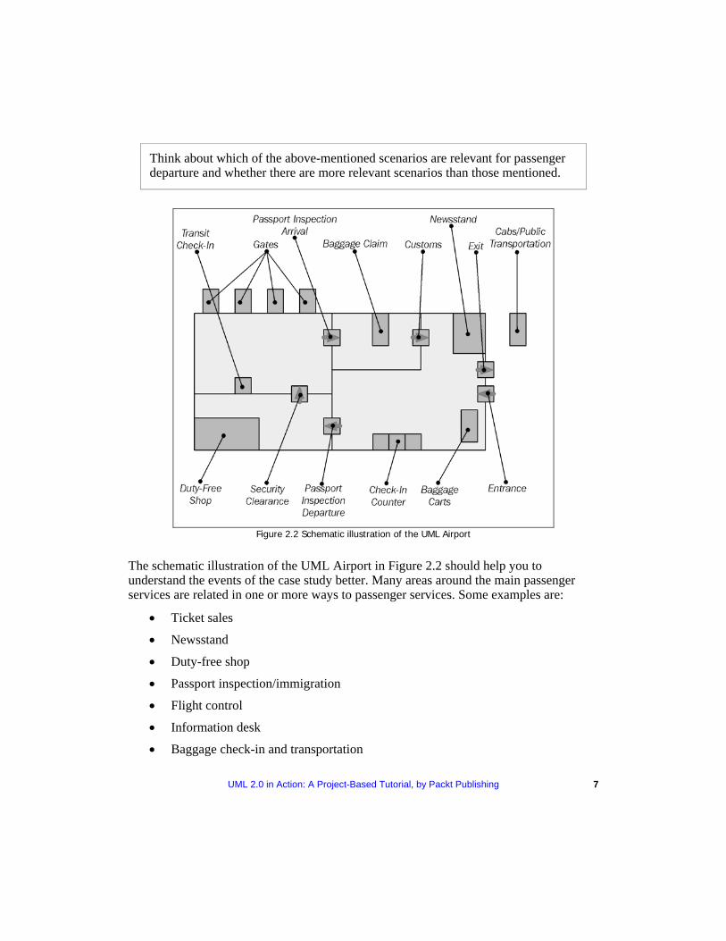
Think about which of the above-mentioned scenarios are relevant for passenger departure and whether there are more relevant scenarios than those mentioned.
Figure 2.2 Schematic illustration of the UML Airport
The schematic illustration of the UML Airport in Figure 2.2 should help you to understand the events of the case study better. Many areas around the main passenger services are related in one or more ways to passenger services. Some examples are:
• Ticket sales
• Newsstand
• Duty-free shop
• Passport inspection/immigration
• Flight control
• Information desk
• Baggage check-in and transportation
8 UML 2.0 in Action: A Project-Based Tutorial, by Packt Publishing
Passenger services have to exchange data with some of these areas. They also have to communicate with other areas of the airport. We will introduce those areas when we discuss business models and models of system integration. Therefore, the case study will be expanded further in the following chapters.
UML Airport is a small airport and the case study has been purposely kept simple. Anyone who has ever been on a flight should be able to understand the examples.
The purpose of the case study is to provide a coherent example throughout the chapters of this book. A few details of the case study require further explanation:
• The plane ticket consists of the actual ticket and up to four additional sections. The ticket is the little booklet that has a separate coupon for every part of the trip. For example, a ticket could contain a coupon for the flight from Zurich to Frankfurt, one for the flight from Frankfurt to London, and one for the return flight from London to Zurich. Each time at check-in the appropriate coupon will be exchanged for a boarding pass. The ticket always stays with the passenger.
• We distinguish between a flight and a flight number. For instance, a flight number could be LH435 or LX016. It stands for a regular flight that occurs at a certain time from the departure airport to the destination airport. A flight, on the other hand, would be, for example, LH435 on 26th August, 2000. It is, so to speak, an execution of a flight number. A flight could be canceled due to bad weather. A flight number is used as long as the airline offers a certain flight regularly.
• We differentiate between three options for check-in: o Normal check-in with luggage at a normal check-in counter o Express check-in without luggage at a special check-in counter
Automated check-in without luggage at a machine
2.2 Models, Views, and Diagrams
2.2.1 What is a Model? Models are often built in the context of business and IT systems in order to better understand existing or future systems. However, a model never fully corresponds to reality. Modeling always means emphasizing and omitting: emphasizing essential details and omitting irrelevant ones. But what is essential and what is irrelevant? There is no universal answer to this question. Rather, the answer depends on what the goals of the model are and who is viewing or reading it.
UML 2.0 in Action: A Project-Based Tutorial, by Packt Publishing 9
Think about what is emphasized or omitted in the following models:
• A wind tunnel model of a car
• A model of a building scaled at 1:50
• A route plan of the subway
• A map
• An organization chart
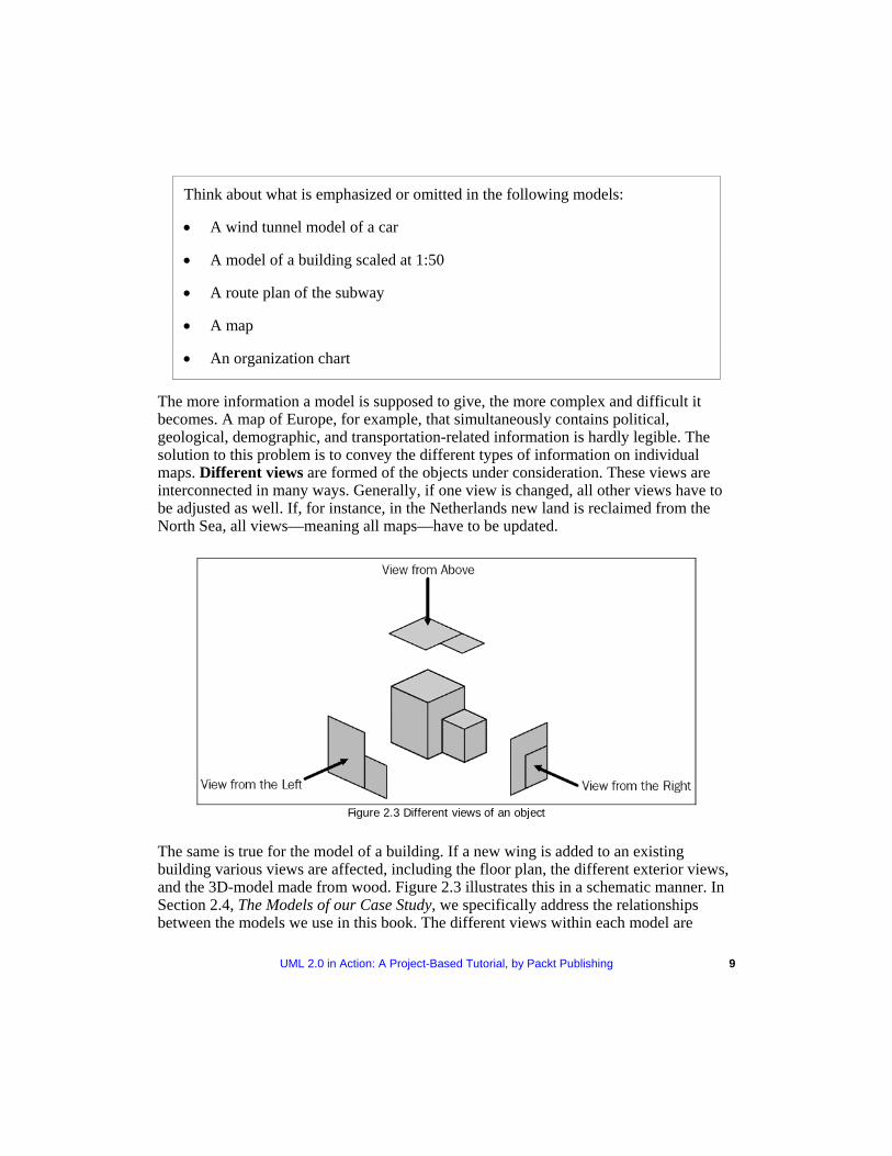
The more information a model is supposed to give, the more complex and difficult it becomes. A map of Europe, for example, that simultaneously contains political, geological, demographic, and transportation-related information is hardly legible. The solution to this problem is to convey the different types of information on individual maps. Different views are formed of the objects under consideration. These views are interconnected in many ways. Generally, if one view is changed, all other views have to be adjusted as well. If, for instance, in the Netherlands new land is reclaimed from the North Sea, all views—meaning all maps—have to be updated.
Figure 2.3 Different views of an object
The same is true for the model of a building. If a new wing is added to an existing building various views are affected, including the floor plan, the different exterior views, and the 3D-model made from wood. Figure 2.3 illustrates this in a schematic manner. In Section 2.4, The Models of our Case Study, we specifically address the relationships between the models we use in this book. The different views within each model are
10 UML 2.0 in Action: A Project-Based Tutorial, by Packt Publishing
described in more detail in Chapter 3, Modeling Business Systems; Chapter 4, Modeling IT Systems; and Chapter 5, Modeling for System Integration.
2.2.2 Why do we Need Models? As a general rule, a model of a system has to perform the following tasks:
• Communication between all involved parties: In order to build the right system, it is essential that all involved parties think along the same lines. It is particularly important that everyone understands the terminology used, that customers agree upon the same requirements, that developers understand these requirements, and that the decisions made can still be understood months later.
• Visualization of all facts for customers, experts, and users: All accumulated facts relevant to the system need to be presented in such a way that everyone concerned can understand them. However, according to our real-life experience, we often hit a wall of resistance when we want to communicate with diagrams instead of text. It is necessary to overcome this resistance. Behind it is often a fear of the unknown; and the diagrams might look a bit complicated at first. Therefore, this book contains directions on how to read each diagram.
• Verification of facts in terms of completeness, consistency, and correctness: A (more or less) formal model makes it possible to verify the facts obtained for completeness, consistency, and correctness. In particular, the clear depiction of interrelationships makes it possible to ask specific questions, and to answer them. We will list these questions with each diagram.
Answer the following questions for yourself:
• When was the last time you felt that you were at cross-purposes when you discussed a system?
• When was the last time you felt that you were discussing the same issue over and over again?
• When was the last time you wished that the consensus you reached during a discussion had been recorded?
UML 2.0 in Action: A Project-Based Tutorial, by Packt Publishing 11
2.2.3 Purpose and Target Group of a Model In real life we often observe that the results of cumbersome, tedious, and expensive modeling simply disappear in a stack of paper on someone's desk. We might ask why this is so. Two factors greatly influence the result of modeling: for whom do we create the model and for what purpose is it supposed to be used. If we don't discuss and define these aspects sufficiently, we run the risk of creating models that don't contain what is important to the user. In other words, if details are not emphasized and omitted appropriately, the model is rendered worthless.
To define the purpose and target group the following questions should be answered:
• How much business expertise can we expect? Can we assume basic knowledge of the subject, or do we have to explain the fundamentals of the model's events and processes?
• What amount of detail does the target group need? What level of complexity does the model permit? If processes and systems are subject to constant changes, a highly detailed model might be unrealistic. This is because, most of the time, it is not possible to maintain those models in a satisfactory manner. A less detailed model requires less effort to develop and update, but it is also less precise.
• How much time does the target group have to read and interpret the model? Prevent your model from disappearing in a stack of paper on someone's desk by choosing the appropriate level of detail and complexity; otherwise, nobody might have enough time to read it.
• What language can be used in the model? Does the target group understand technical business terms? Do they understand IT terminology? Let's clarify with an easy example: If a bottle filled with water is labeled 'water', virtually anyone who can read will understand the bottle's content. However, if the bottle is labeled 'H2O'—even though this is correct—we reach a much smaller group of people, for example, the workers of a chemistry lab. Yet, the additional benefit is that it shows the composition of the content: hydrogen and oxygen. In either case, you will have to decide what 'label' is most appropriate for your target group.
• What level of abstraction should you choose? The less abstract a model, the more comprehensible, and clear it is for the user. This is because a less abstract model is closer to the user's actual use and language. On the other hand, models with a high level of abstraction are more reusable and they are more easily converted into IT systems. We can also prove more accurately that they are correct. IT specialists probably manage highly abstract models best. Users, on the other hand, might pull their hair out if asked to deal with a model like that.
Practical Tips Compromises have to be made between the level of abstraction, clarity, and the amount of detail used for a model. It is possible to develop several model components, differing in degree of formality and detail, in order to satisfy different target groups. In this way communication between model builders, customers, users, and developers can be facilitated much more easily. It is important not to 'overdo' it, but to adjust the model to its target groups and their uses.
Analysis or design patterns are example models that describe common design and modeling methods. You should, whenever possible, look for these example models: on the Internet, in books (for example, Martin Fowler: Analysis Patterns: Reusable Object Models, Addison-Wesley, 1999), in magazines, or ask your coworkers.
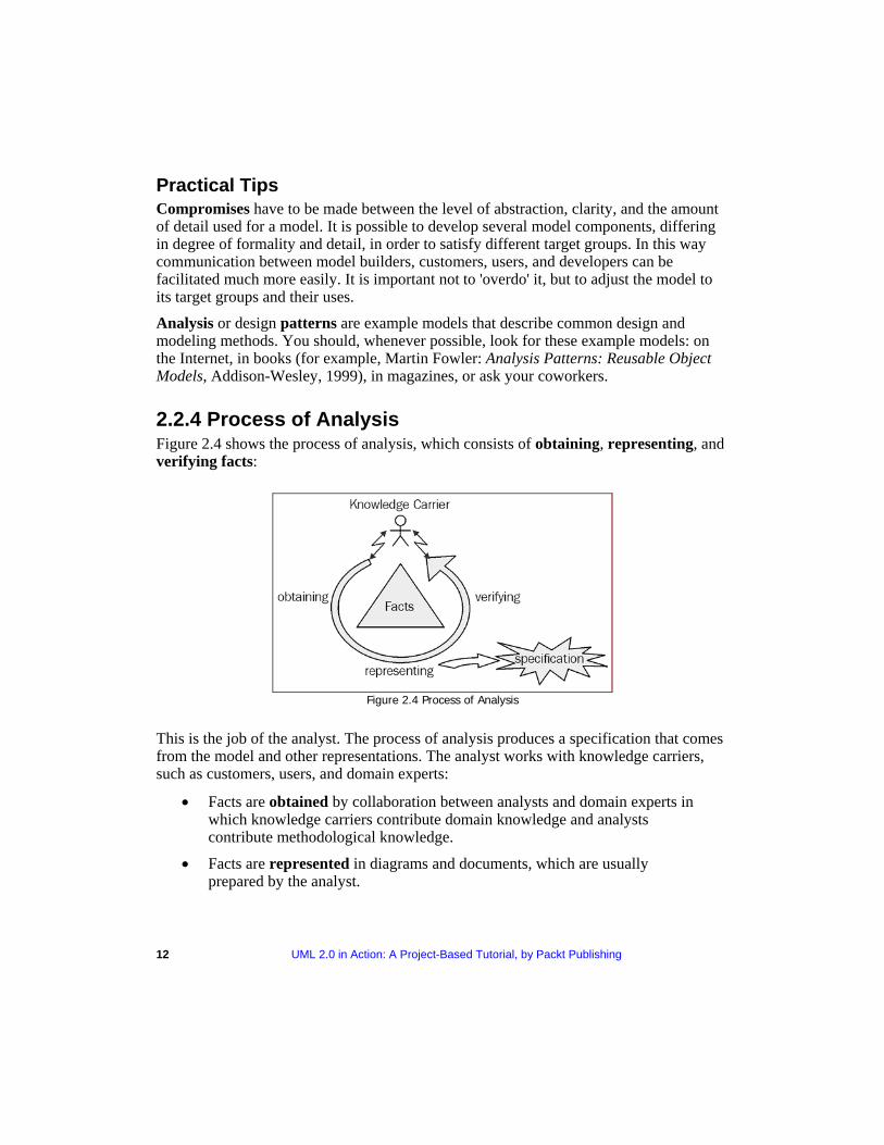
2.2.4 Process of Analysis obtaining
12 UML 2.0 in Action: A Project-Based Tutorial, by Packt Publishing
Figure 2.4 shows the process of analysis, which consists of , representing, and verifying facts:
Figure 2.4 Process of Analysis
This is the job of the analyst. The process of analysis produces a specification that comes from the model and other representations. The analyst works with knowledge carriers, such as customers, users, and domain experts:
• Facts are obtained by collaboration between analysts and domain experts in which knowledge carriers contribute domain knowledge and analysts contribute methodological knowledge.
• Facts are represented in diagrams and documents, which are usually prepared by the analyst.
UML 2.0 in Action: A Project-Based Tutorial, by Packt Publishing 13
• Facts are verified only by knowledge carriers, since they alone can decide if the presented facts are correct. Verification is absolutely essential. Without it we might have pretty diagrams, but the probability is high that the facts represented are faulty. In simple terms: development of a model without verification is absolutely worthless!
Practical Tips It is impossible to develop and verify a usable model without mastering the technical foundations of a topic. Where do we find these knowledge carriers who know something about the systems that we want to model? We have had good experiences with the following groups of people:
• People who are involved in performing, operating, and controlling business processes
• Users of similar or related IT systems
• Customers, who are often critical and creative knowledge carriers
• Business Partners
• Domain Experts
• Management
• External Observers
Several helpful techniques have proven to be useful for the analysis and understanding of business processes:
• Observing employees at work
• Participating in the investigated business processes
• Taking the role of an outsider (e.g. of a customer)
• Carrying out surveys
• Conducting interviews
• Brainstorming with everyone involved
• Discussing with domain experts
• Reviewing existing forms, documentation, specifications, handbooks, and work tools
• Describing the organizational structure and workflow management (organization charts, etc.)
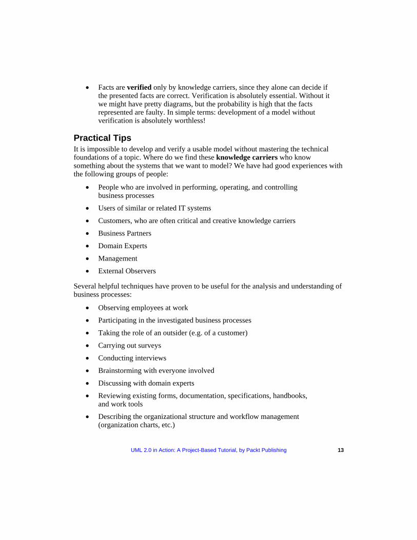
2.2.5 Diagrams as Views Each particular UML diagram corresponds to one view of a model of a system. Depending on the type of diagram used, different aspects are either emphasized or omitted. All the different views combined result in a good model of a system. Most of the UML diagrams are graphs (as shown in Figure 2.5), implying that they consist of elements that are connected through lines:
Figure 2.5 Diagram as graphs
In order to read diagrams, you have to know what types of elements and lines are allowed and what they mean. We will explain this for the diagrams we use throughout the following chapters.
14 UML 2.0 in Action: A Project-Based Tutorial, by Packt Publishing
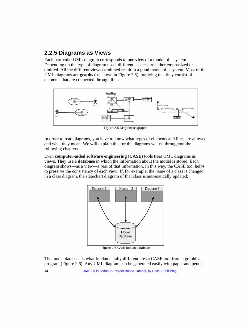
Even computer aided software engineering- (CASE) tools treat UML diagrams as views. They use a database in which the information about the model is stored. Each diagram shows—as a view—a part of that information. In this way, the CASE tool helps to preserve the consistency of each view. If, for example, the name of a class is changed in a class diagram, the statechart diagram of that class is automatically updated:
Figure 2.6 CASE tool as database
The model database is what fundamentally differentiates a CASE tool from a graphical program (Figure 2.6). Any UML diagram can be generated easily with paper and pencil
UML 2.0 in Action: A Project-Based Tutorial, by Packt Publishing 15
or a graphical program. In this case, however, the various diagrams are nothing more than drawings. Only the use of a CASE tool with a database, according to UML specifications, permits consistent collection, management, and modification of model information. UML provides its own database model: the UML meta-model, a component of the UML specifications ("OMG: Unified Modeling Language: Infrastructure, Version 2.0, Final Adopted Specification, September 2003, and OMG: Unified Modeling Language: Superstructure, Version 2.0, Revised Final Adopted Specification, October 2004": http://www.omg.org). All elements found in UML diagrams, as well as the descriptions of these elements, are contained in the UML meta-model. It states, for example, that a class can have attributes and methods. This "data model" of UML as a language, is the foundation of the model databases of all UML CASE tools. Unfortunately, many CASE tools are hungry for resources, expensive, poorly developed, cumbersome, and require extensive training. Despite this, except for very small projects, their use is worthwhile.
2.3 Information Systems and IT Systems In almost all occupations, part of the job is dealing with information. It has been this way for thousands of years and is one of the reasons behind the development of writing. Some of the oldest texts found in Europe include, for instance, stock lists from the palace of Knossos in Crete. If we were able to watch the stock managers work as they did 3,500 years ago, we could probably map the business processes that people followed back then. We could see that these people were dealing with suppliers and buyers, that they were exchanging goods, and that they kept written records of their business activities. The same was true for a Roman olive merchant 1,500 years later, for a Hanseatic merchant's trading office in fifteenth century Northern Germany, or at Lloyd's of London at the beginning of the last century.
In the above examples, more or less complex information systems were used to handle daily tasks. The purpose of these information systems was, and is, to manage the information needed to operate a business. Of course, all of this took place without computers. Information systems were supported by other techniques such as chalkboards, large filing systems, and index cards. Today, computers allow us to implement information systems as IT systems. This creates new possibilities that would probably be unthinkable for the Roman olive merchant. But basically, the point is still to provide and to process data that is needed for dealing with everyday business processes. We will generally be talking about IT systems in this book, since we assume that information systems modeled with UML are implemented by IT technology.
In our case study—passenger services at UML Airport—employees at the check-in deal with passengers, plane tickets, and flights that are real. On the other hand, there is a representation or image of these passengers, plane tickets, and flights in the information system. These images consist of information about the passengers, tickets, and flights stored in the information system, needed for operating processes, as shown in Figure 2.7:
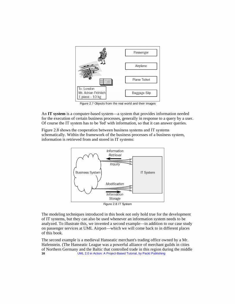
Figure 2.7 Objects from the real world and their images
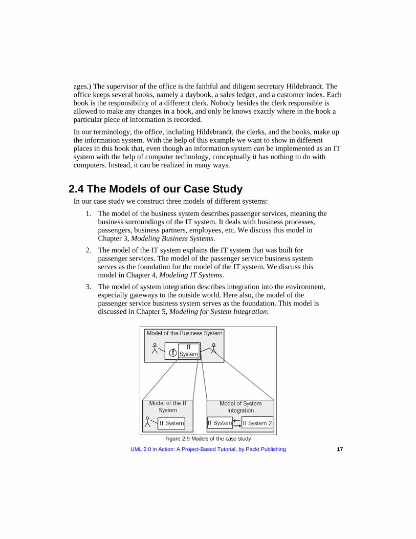
IT systemAn is a computer-based system—a system that provides information needed for the execution of certain business processes, generally in response to a query by a user. Of course the IT system has to be 'fed' with information, so that it can answer queries.
Figure 2.8 shows the cooperation between business systems and IT systems schematically. Within the framework of the business processes of a business system, information is retrieved from and stored in IT systems:
Figure 2.8 IT System
The modeling techniques introduced in this book not only hold true for the development of IT systems, but they can also be used whenever an information system needs to be analyzed. To illustrate this, we invented a second example—in addition to our case study on passenger services at UML Airport—which we will come back to in different places of this book.
16 UML 2.0 in Action: A Project-Based Tutorial, by Packt Publishing
The second example is a medieval Hanseatic merchant's trading office owned by a Mr. Hafenstein. (The Hanseatic League was a powerful alliance of merchant guilds in cities of Northern Germany and the Baltic that controlled trade in this region during the middle
ages.) The supervisor of the office is the faithful and diligent secretary Hildebrandt. The office keeps several books, namely a daybook, a sales ledger, and a customer index. Each book is the responsibility of a different clerk. Nobody besides the clerk responsible is allowed to make any changes in a book, and only he knows exactly where in the book a particular piece of information is recorded.
In our terminology, the office, including Hildebrandt, the clerks, and the books, make up the information system. With the help of this example we want to show in different places in this book that, even though an information system can be implemented as an IT system with the help of computer technology, conceptually it has nothing to do with computers. Instead, it can be realized in many ways.
2.4 The Models of our Case Study In our case study we construct three models of different systems:
1. The model of the business system describes passenger services, meaning the business surroundings of the IT system. It deals with business processes, passengers, business partners, employees, etc. We discuss this model in Chapter 3, Modeling Business Systems.
2. The model of the IT system explains the IT system that was built for passenger services. The model of the passenger service business system serves as the foundation for the model of the IT system. We discuss this model in Chapter 4, Modeling IT Systems.
3. The model of system integration describes integration into the environment, especially gateways to the outside world. Here also, the model of the passenger service business system serves as the foundation. This model is discussed in Chapter 5, Modeling for System Integration:
Figure 2.9 Models of the case study
UML 2.0 in Action: A Project-Based Tutorial, by Packt Publishing 17
18 UML 2.0 in Action: A Project-Based Tutorial, by Packt Publishing
All three models are needed to build and integrate IT systems; the model of the IT system alone is insufficient. This is true not only for our case study, but also for all other cases.
You can see in Figure 2.9 that the model of the business system provides the foundation for all other models. In this way, it constitutes the basis to work from for everyone involved in the project. Because of this, it is of great advantage to use a unified modeling language, which can be understood by people from the different departments as well as from information technology. This enables a smooth exchange of models between the various areas. It also significantly eases verification of the models. We are convinced that UML functions as a link that has the ability to close the existing gap between the technical requirements and the actual performance characteristics of IT systems.
2.5 History of UML: Methods and Notations In its short history, information technology has already produced a plethora of methods and notations. We have methods and notations for design, structure, processing, and storage of information. We also have methods for the planning, modeling, implementation, assembly, testing, documentation, adjustment, etc. of systems. Some of the concepts used are relatively fundamental, and because of that, they can also be found beyond the field of information technology. One example of that is inheritance, which is present in nature, but is also a cornerstone of object-oriented programming.
Until about the 1970s, software developers viewed the development of software as an artistic venture. But because systems became more and more complex, software development and maintenance could no longer be conquered with this creative-individual approach. Eventually, this approach led to the software crisis.
This crisis leads to the engineering approach (software engineering) and structured programming. Methods were developed for the structuring of systems and for the processes of design, development, and maintenance. Process-oriented approaches, for example the Hierarchy Input Processing Output (HIPO) method, emphasized the functionality of systems. With this method the total system is divided into smaller components through functional decomposition.
Figure 2.10 gives a visual overview (hierarchical diagram) of the sub-functions in the invoice example. An input-process-output schema describes every functional element.
At the same time, data-structure oriented approaches were developed, such as the Jackson method, in which the program structure is derived from the graphical display of data structures.
Figure 2.11 shows, in the left-hand column, the structure of an inventory data set. The right-hand column shows the program structure that was derived from the data structure:
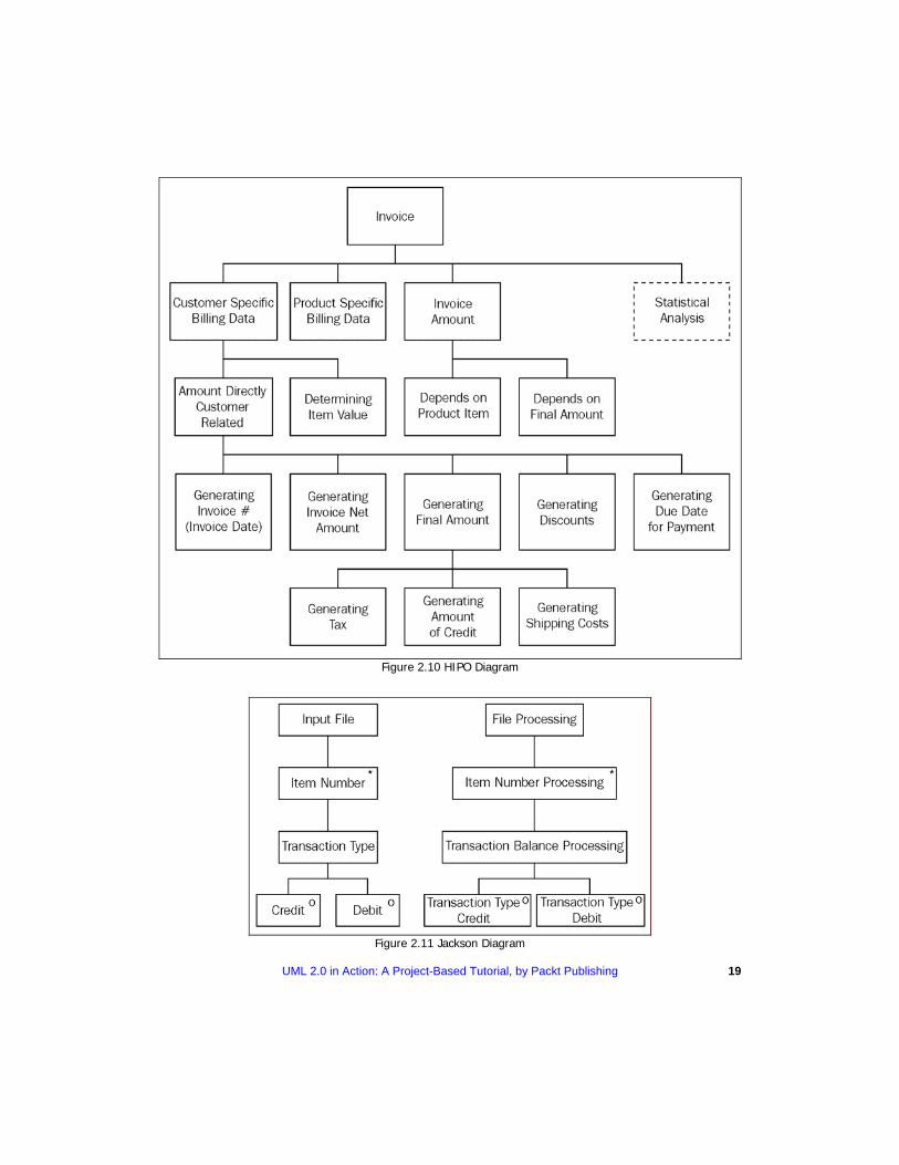
Figure 2.10 HIPO Diagram
Figure 2.11 Jackson Diagram
UML 2.0 in Action: A Project-Based Tutorial, by Packt Publishing 19
20 UML 2.0 in Action: A Project-Based Tutorial, by Packt Publishing
In all these methods and notations, we split the system into two portions—a data section and a procedure section. This is clearly recognizable in older programming languages such as COBOL. Data flow-charts, structure charts, HIPO diagrams, and Jackson diagrams are used to illustrate the range of functions. Naturally, these early methods emphasized the development of new systems.
In the 1980s, classical structural analysis was developed further. Developers generated entity relationship diagrams for data modeling and Petri nets for process modeling.
As systems became more complex, no longer could every system be designed "from scratch". Properties, such as maintainability and re-usability, became more and more important. Object-oriented programming languages were developed, and with them, the first object-oriented modeling languages emerged in the 1970s and 1980s. In the 1990s, the first publications on object-oriented analysis and object-oriented design became available to the public. In the mid-1990s, already more than 50 object-oriented methods existed, as well as just as many design formats. A unified modeling language seemed indispensable.
At the beginning of the 1990s, the object-oriented methods of Grady Booch and James Rumbaugh were widely used. In October 1994, the Rational Software Corporation (part of IBM since February 2003) began the creation of a unified modeling language. First, they agreed upon a standardization of notation (language), since this seemed less elaborate than the standardization of methods. In doing so, they integrated the Booch Method of Grady Booch, the Object Modeling Technique (OMT) by James Rumbaugh, and Object-Oriented Software Engineering (OOSE), by Ivar Jacobsen, with elements of other methods and published this new notation under the name UML, version 0.9. The goal was not to formulate a completely new notation, but to adapt, to expand, and to simplify the existing and accepted types of diagrams of several object-oriented methods, such as class diagrams, Jacobson's Use Case Diagrams, or Harel's Statechart Diagrams. The means of representation that were used in structured methods were applied to UML. Thus, UML's activity diagrams are, for example, influenced by the make-up of data flow charts and Petri nets.
What is outstanding and new in UML is not its content, but its standardization to a single unified language with formally defined meaning.
Well-known companies, such as IBM, Oracle, Microsoft, Digital, Hewlett-Packard, and Unisys were included in the further development of UML. In 1997, UML version 1.1 was submitted to and approved by the OMG. UML version 1.2, with editorial adaptations, was released in 1998, followed by version 1.3 a year later, and UML 1.5 in March, 2003. Developers had already been working on version 2.0 of UML since the year 2000, and it was approved as a Final Adopted Specification by OMG in June, 2003. When this book went to print in June, 2005 the final stage of adoption by OMG as an Available Specification was not yet completed.
UML 2.0 in Action: A Project-Based Tutorial, by Packt Publishing 21
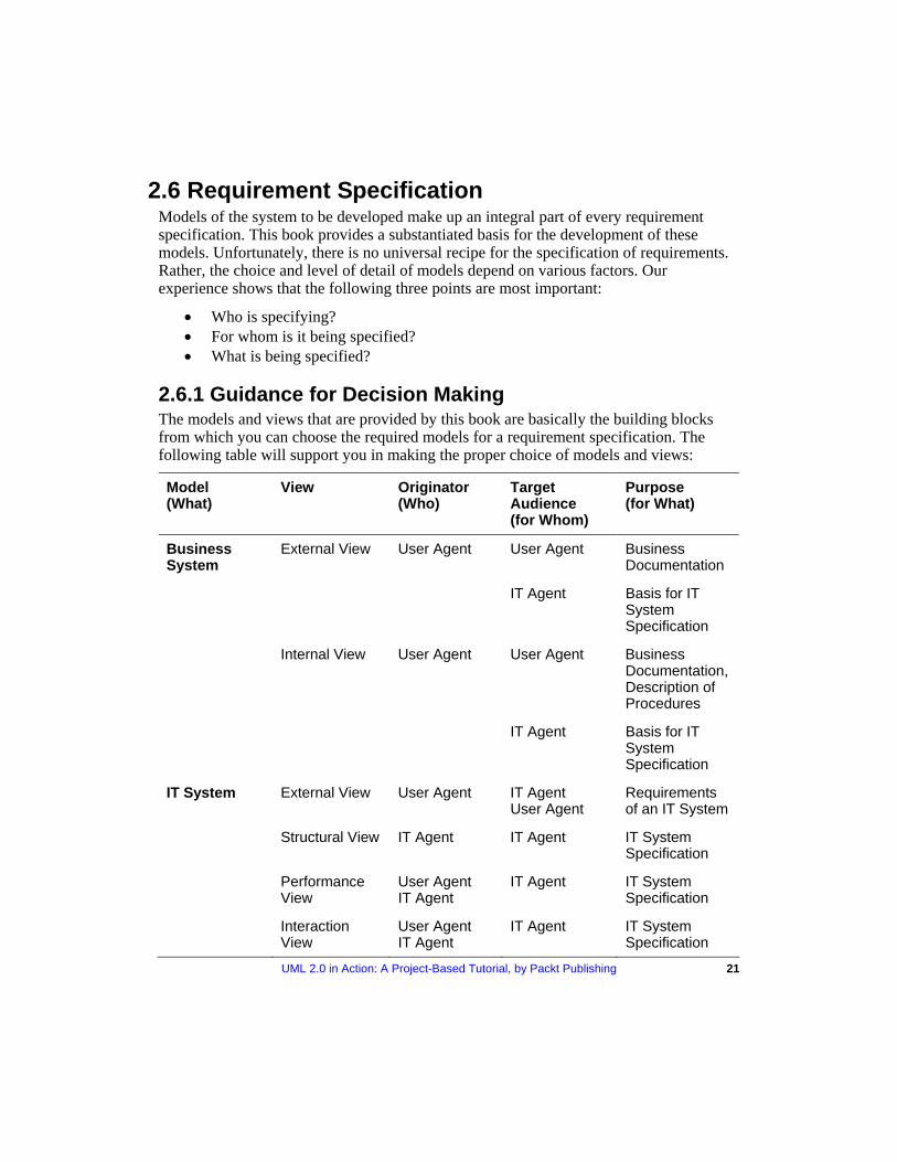
2.6 Requirement Specification Models of the system to be developed make up an integral part of every requirement specification. This book provides a substantiated basis for the development of these models. Unfortunately, there is no universal recipe for the specification of requirements. Rather, the choice and level of detail of models depend on various factors. Our experience shows that the following three points are most important:
• Who is specifying? • For whom is it being specified? • What is being specified?
2.6.1 Guidance for Decision Making The models and views that are provided by this book are basically the building blocks from which you can choose the required models for a requirement specification. The following table will support you in making the proper choice of models and views:
Model (What)
View Originator (Who)
Target Audience (for Whom)
Purpose (for What)
Business System
External View User Agent User Agent Business Documentation
IT Agent Basis for IT System Specification
Internal View User Agent User Agent Business Documentation,Description of Procedures
IT Agent Basis for IT System Specification
IT System External View User Agent IT Agent User Agent
Requirements of an IT System
Structural View IT Agent IT Agent IT System Specification
Performance View
User Agent IT Agent
IT Agent IT System Specification
Interaction View
User Agent IT Agent
IT Agent IT System Specification
22 UML 2.0 in Action: A Project-Based Tutorial, by Packt Publishing
Model (What)
View Originator (Who)
Target Audience (for Whom)
Purpose (for What)
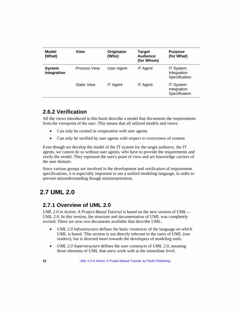
System Integration
Process View User Agent IT Agent IT System Integration Specification
Static View IT Agent IT Agent IT System Integration Specification
2.6.2 Verification All the views introduced in this book describe a model that documents the requirements from the viewpoint of the user. This means that all utilized models and views:
• Can only be created in cooperation with user agents
• Can only be verified by user agents with respect to correctness of content
Even though we develop the model of the IT system for the target audience, the IT agents, we cannot do so without user agents, who have to provide the requirements and verify the model. They represent the user's point of view and are knowledge carriers of the user domain.
Since various groups are involved in the development and verification of requirement specifications, it is especially important to use a unified modeling language, in order to prevent misunderstanding though misinterpretation.
2.7 UML 2.0
2.7.1 Overview of UML 2.0 UML 2.0 in Action: A Project-Based Tutorial is based on the new version of UML—UML 2.0. In this version, the structure and documentation of UML was completely revised. There are now two documents available that describe UML:
• UML 2.0 Infrastructure defines the basic constructs of the language on which UML is based. This section is not directly relevant to the users of UML (our readers), but is directed more towards the developers of modeling tools.
• UML 2.0 Superstructure defines the user constructs of UML 2.0, meaning those elements of UML that users work with at the immediate level.
Among other things, this revision of UML was created to pursue the following goals:
• To restructure and refine UML so that usability, implementation, and adaptation are simplified.
• The UML infrastructure is supposed to: o Provide a reusable meta-language core, with which UML can
define itself Provide mechanisms for the adjustment of language
• The UML superstructure is supposed to: o Feature better support for component-based development o Improve constructs for the specification of architecture
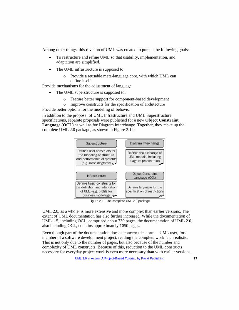
Provide better options for the modeling of behavior In addition to the proposal of UML Infrastructure and UML Superstructure specifications, separate proposals were published for a new Object Constraint Language (OCL) as well as for Diagram Interchange. Together, they make up the complete UML 2.0 package, as shown in Figure 2.12:
Figure 2.12 The complete UML 2.0 package
UML 2.0, as a whole, is more extensive and more complex than earlier versions. The extent of UML documentation has also further increased. While the documentation of UML 1.5, including OCL, comprised about 730 pages, the documentation of UML 2.0, also including OCL, contains approximately 1050 pages.
Even though part of the documentation doesn't concern the 'normal' UML user, for a member of a software development project, reading the complete work is unrealistic. This is not only due to the number of pages, but also because of the number and complexity of UML constructs. Because of this, reduction to the UML constructs necessary for everyday project work is even more necessary than with earlier versions. UML 2.0 in Action: A Project-Based Tutorial, by Packt Publishing 23
24 UML 2.0 in Action: A Project-Based Tutorial, by Packt Publishing
From this follow two conclusions for our book UML 2 0 in Action A Project-Based . : Tutorial.
The concept of this book is to show a very simplified picture of UML. This is becoming even more important with the increasing scope of UML, since the accessibility of UML did not become any greater with version 2.0.
Fortunately, many of the new features of UML 2.0 have little or no influence at the level of detail used in this book. Consequently, there are only a few changes compared to the earlier German editions of UML 2 0 in Action . : A Project-Based Tutorial . The restricted scope of our book ensures stability towards the changes in new UML versions.
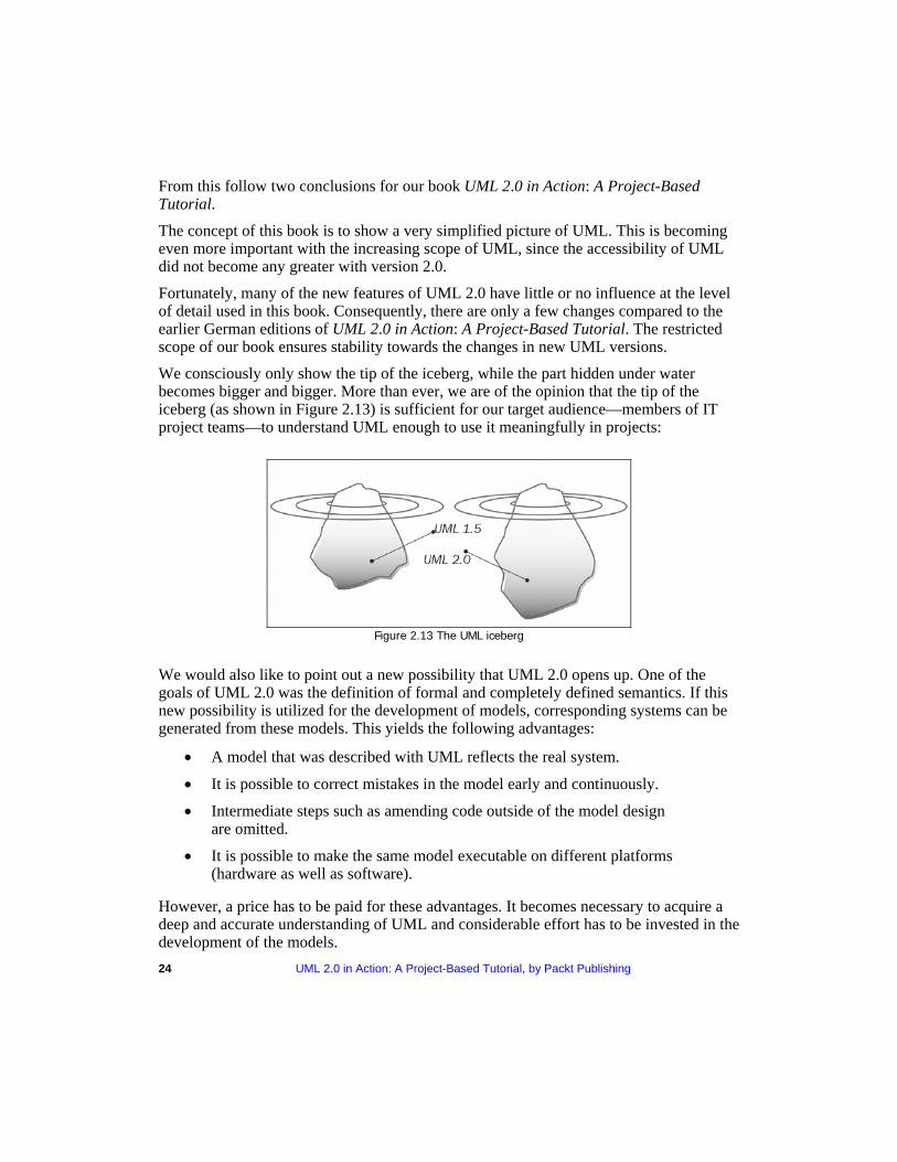
We consciously only show the tip of the iceberg, while the part hidden under water becomes bigger and bigger. More than ever, we are of the opinion that the tip of the iceberg (as shown in Figure 2.13) is sufficient for our target audience—members of IT project teams—to understand UML enough to use it meaningfully in projects:
Figure 2.13 The UML iceberg
We would also like to point out a new possibility that UML 2.0 opens up. One of the goals of UML 2.0 was the definition of formal and completely defined semantics. If this new possibility is utilized for the development of models, corresponding systems can be generated from these models. This yields the following advantages:
• A model that was described with UML reflects the real system.
• It is possible to correct mistakes in the model early and continuously.
• Intermediate steps such as amending code outside of the model design are omitted.
• It is possible to make the same model executable on different platforms (hardware as well as software).
However, a price has to be paid for these advantages. It becomes necessary to acquire a deep and accurate understanding of UML and considerable effort has to be invested in the development of the models.
UML 2.0 in Action: A Project-Based Tutorial, by Packt Publishing 25
2.7.2 Effects on the Business System Model Some changes made in performance modeling enhanced the possibilities for modeling business systems. First, we'll give examples of several of the changes and improvements.
Activity diagrams are no longer special cases of the statechart diagram. Initially, this fact was not relevant for the normal UML user. However, in addition to the new autonomy in the meta-model, several other changes and improvements were made:
Until now, the separate steps in the activity diagram were referred to as activities. Now the entire diagram is called an activity, whereas the steps previously called activities are now referred to as actions. An action can call a primary operation as well as another activity. This enables flexible modulation in the top-down view of models.
A division does not necessarily have to be re-synchronized.
An activity can have more than one initial state. With this, several events can be started at the same time.
Input and output parameters can be added to an activity.
One of the improvements made in the sequence diagram is the addition of so-called operators. These operators make it possible to package several actions/activities within a sequence diagram. For instance, operators can be used to refer to other sequence diagrams or individual sequences. Appropriate operators can also represent iterations. With the newly introduced operators, sequence diagrams now support a top-down view.
OCL is now an inherent part of UML. It can be used to describe agreements, invariants, preconditions, and post conditions within UML models, which enables more precise modeling of business systems and business processes.
2.7.3 Effects on the IT System Model The diagrams that we have used in this book in the different views of the IT system did not undergo any significant changes.
The biggest change occurred in the notation of the sequence diagram. Here, among other things, the interaction reference is available as a construct for modularization. However, nothing changed concerning the meaning and functionality of sequence diagrams at the level of detail used in this book. The same holds true for the class diagram and the case diagram.
Statechart diagrams underwent the most interesting changes for the modeling of IT systems: connection points allow, for example, better modulation of statechart diagrams. However, we decided not to use this language element in our simplified approach to UML.
26 UML 2.0 in Action: A Project-Based Tutorial, by Packt Publishing
2.7.4 Effects on the Systems Integration Model Of course, the improvements in behavioral modeling also had an effect on the process view in the systems integration model. A significant improvement is the ability to add input and output parameters to activities (see Section 2.7.2, Effects on the Business System Model).
Hardly any changes were made in the area of static views, meaning the design of business objects with class diagrams.
In addition to the changes that were made within the framework of UML 2.0, the UML profile for Enterprise Application Integration (EAI) is of increasing importance in the field of system integration. Besides the basic operations needed in the field of system integration, it shows the data meta-models of various programming languages that are not object-oriented. However, this occurs at a more detailed level, which has no influence upon this text.
2.7.5 Conclusion For the normal user, UML 2.0 does not turn the previous versions of UML upside down, but represents an improvement on existing concepts. It is probably wise to use UML 2.0 for future models. On the other hand, it should be possible to continue using existing constructs and models based on earlier UML versions. For ongoing projects the advantages (more exact modeling) have to be weighed against the disadvantages (additional work).
UML 2.0 in Action A Project-Based Tutorial The OMG Specification states:
"The Unified Modeling Language (UML) is a graphical language for visualizing, specifying, constructing, and documenting the artifacts of a software-intensive system."
Modeling is an essential part of large software projects, which also helps in the development of medium and small projects. UML can be used to model a variety of systems: software systems, business systems, or any other system. With its changes and extensions, UML 2.0 now supports the modeling of business processes much better.
What This Book Covers This book shows how, with UML, simple models of business processes and specification models can be created and read with little effort. Most books deal with UML almost in its entirety. However, often lack of time, previous knowledge, or motivation to deal with the topic with the necessary intensity prevents us from understanding the material completely and putting it into action. This book is meant for exactly these cases. It presents UML only partially and in a simplified manner. We put together those parts of UML whose application has proven to be practical.
Chapter 1 introduces us to UML and lists the advantages of using UML as a Modeling Language. Chapter 2 introduces us to the case study. The purpose of choosing a case study is to provide a coherent example through the chapters of this book. The chapter also explains several basic terms and concepts like models, views, diagrams, information systems, methods, and notations. The models and views provided by this book help choose the most suitable model for a requirement specification.
Chapter 3 discusses the construction of business system models. It explains the benefits of the different views in a business system and discusses the elements of each view. It also provides instructions about how to construct use case diagrams.
Chapter 4 illustrates how a conceptual model of an IT system can be developed with the help of UML. Chapter 5 describes the integration of the IT system into its environment.

It discusses how to model the messages that are exchanged between the various IT systems, and the processes that are necessary to exchange these messages.
Where to buy this book You can buy UML 2.0 in Action A Project-Based Tutorial direct from the Packt Publishing website: http://www.packtpub.com/uml/book This book carries at least a 10% discount on the website as well as free shipping to the US, UK, Europe, Australia & New Zealand.
Alternatively, you can buy the book from Amazon, BN.com, Computer Manuals and most internet book retailers.
www.PacktPub.com