Embed Size (px)
Citation preview

Umbrello UML Modeller Handbook

Umbrello UML Modeller Handbook
2

Contents
1 Introduction 7
2 UML Basics 82.1 About UML . . . . . . . . . . . . . . . . . . . . . . . . . . . . . . . . . . . . . . . . . 82.2 UML Elements . . . . . . . . . . . . . . . . . . . . . . . . . . . . . . . . . . . . . . . . 9
2.2.1 Use Case Diagram . . . . . . . . . . . . . . . . . . . . . . . . . . . . . . . . . 9
2.2.1.1 Use Case . . . . . . . . . . . . . . . . . . . . . . . . . . . . . . . . . 92.2.1.2 Actor . . . . . . . . . . . . . . . . . . . . . . . . . . . . . . . . . . . 102.2.1.3 Use Case Description . . . . . . . . . . . . . . . . . . . . . . . . . . 10
2.2.2 Class Diagram . . . . . . . . . . . . . . . . . . . . . . . . . . . . . . . . . . . . 10
2.2.2.1 Class . . . . . . . . . . . . . . . . . . . . . . . . . . . . . . . . . . . . 112.2.2.1.1 Attributes . . . . . . . . . . . . . . . . . . . . . . . . . . . 112.2.2.1.2 Operations . . . . . . . . . . . . . . . . . . . . . . . . . . . 11
2.2.2.1.3 Templates . . . . . . . . . . . . . . . . . . . . . . . . . . . 11
2.2.2.2 Class Associations . . . . . . . . . . . . . . . . . . . . . . . . . . . . 112.2.2.2.1 Generalization . . . . . . . . . . . . . . . . . . . . . . . . . 122.2.2.2.2 Associations . . . . . . . . . . . . . . . . . . . . . . . . . . 122.2.2.2.3 Aggregation . . . . . . . . . . . . . . . . . . . . . . . . . . 12
2.2.2.2.4 Composition . . . . . . . . . . . . . . . . . . . . . . . . . . 13
2.2.2.3 Other Class Diagram Items . . . . . . . . . . . . . . . . . . . . . . . 13
2.2.2.3.1 Interfaces . . . . . . . . . . . . . . . . . . . . . . . . . . . . 132.2.2.3.2 Datatypes . . . . . . . . . . . . . . . . . . . . . . . . . . . . 13
2.2.2.3.3 Enums . . . . . . . . . . . . . . . . . . . . . . . . . . . . . 132.2.2.3.4 Packages . . . . . . . . . . . . . . . . . . . . . . . . . . . . 13
2.2.3 Sequence Diagrams . . . . . . . . . . . . . . . . . . . . . . . . . . . . . . . . . 13
2.2.4 Collaboration Diagrams . . . . . . . . . . . . . . . . . . . . . . . . . . . . . . 14
2.2.5 State Diagram . . . . . . . . . . . . . . . . . . . . . . . . . . . . . . . . . . . . 15
2.2.5.1 State . . . . . . . . . . . . . . . . . . . . . . . . . . . . . . . . . . . . 162.2.6 Activity Diagram . . . . . . . . . . . . . . . . . . . . . . . . . . . . . . . . . . 16
2.2.6.1 Activity . . . . . . . . . . . . . . . . . . . . . . . . . . . . . . . . . . 17
2.2.7 Helper Elements . . . . . . . . . . . . . . . . . . . . . . . . . . . . . . . . . . 17
2.2.8 Component Diagrams . . . . . . . . . . . . . . . . . . . . . . . . . . . . . . . 18

Umbrello UML Modeller Handbook
2.2.9 Deployment Diagrams . . . . . . . . . . . . . . . . . . . . . . . . . . . . . . . 18
2.2.10 Entity Relationship Diagrams . . . . . . . . . . . . . . . . . . . . . . . . . . . 18
2.2.10.1 Entity . . . . . . . . . . . . . . . . . . . . . . . . . . . . . . . . . . . 19
2.2.10.1.1 Entity Attributes . . . . . . . . . . . . . . . . . . . . . . . . 19
2.2.10.1.2 Constraints . . . . . . . . . . . . . . . . . . . . . . . . . . . 192.2.11 Extended Entity Relationship (EER) Diagram Concepts . . . . . . . . . . . . 19
2.2.11.1 Specialization . . . . . . . . . . . . . . . . . . . . . . . . . . . . . . 19
2.2.11.1.1 Disjoint Specialization . . . . . . . . . . . . . . . . . . . . 20
2.2.11.1.2 Overlapping Specialization . . . . . . . . . . . . . . . . . 20
2.2.11.1.3 Category . . . . . . . . . . . . . . . . . . . . . . . . . . . . 21
3 Working with Umbrello UML Modeller 22
3.1 User Interface . . . . . . . . . . . . . . . . . . . . . . . . . . . . . . . . . . . . . . . . 223.1.1 Tree View . . . . . . . . . . . . . . . . . . . . . . . . . . . . . . . . . . . . . . 233.1.2 Documentation and Command History Window . . . . . . . . . . . . . . . . 23
3.1.3 Work Area . . . . . . . . . . . . . . . . . . . . . . . . . . . . . . . . . . . . . . 233.2 Creating, Loading and Saving Models . . . . . . . . . . . . . . . . . . . . . . . . . . 24
3.2.1 New Model . . . . . . . . . . . . . . . . . . . . . . . . . . . . . . . . . . . . . 243.2.2 Save Model . . . . . . . . . . . . . . . . . . . . . . . . . . . . . . . . . . . . . 243.2.3 Load Model . . . . . . . . . . . . . . . . . . . . . . . . . . . . . . . . . . . . . 24
3.3 Editing Models . . . . . . . . . . . . . . . . . . . . . . . . . . . . . . . . . . . . . . . 24
3.4 Adding and Removing Diagrams . . . . . . . . . . . . . . . . . . . . . . . . . . . . . 25
3.4.1 Creating Diagrams . . . . . . . . . . . . . . . . . . . . . . . . . . . . . . . . . 25
3.4.2 Removing Diagrams . . . . . . . . . . . . . . . . . . . . . . . . . . . . . . . . 25
3.4.3 Renaming Diagrams . . . . . . . . . . . . . . . . . . . . . . . . . . . . . . . . 25
3.5 Editing Diagrams . . . . . . . . . . . . . . . . . . . . . . . . . . . . . . . . . . . . . . 25
3.5.1 Insert Elements . . . . . . . . . . . . . . . . . . . . . . . . . . . . . . . . . . . 263.5.2 Deleting Elements . . . . . . . . . . . . . . . . . . . . . . . . . . . . . . . . . 26
3.5.3 Editing Elements . . . . . . . . . . . . . . . . . . . . . . . . . . . . . . . . . . 26
3.5.4 Editing Classes . . . . . . . . . . . . . . . . . . . . . . . . . . . . . . . . . . . 27
3.5.4.1 Class General Settings . . . . . . . . . . . . . . . . . . . . . . . . . . 27
3.5.4.2 Class Attribute Settings . . . . . . . . . . . . . . . . . . . . . . . . . 27
3.5.4.3 Class Operations Settings . . . . . . . . . . . . . . . . . . . . . . . . 27
3.5.4.4 Class Template Settings . . . . . . . . . . . . . . . . . . . . . . . . . 27
3.5.4.5 Class Associations Page . . . . . . . . . . . . . . . . . . . . . . . . . 27
3.5.4.6 Class Display Page . . . . . . . . . . . . . . . . . . . . . . . . . . . 27
3.5.4.7 Class Style Page . . . . . . . . . . . . . . . . . . . . . . . . . . . . . 28
3.5.5 Associations . . . . . . . . . . . . . . . . . . . . . . . . . . . . . . . . . . . . . 283.5.5.1 Anchor Points . . . . . . . . . . . . . . . . . . . . . . . . . . . . . . 28
3.5.6 Notes, Text and Boxes . . . . . . . . . . . . . . . . . . . . . . . . . . . . . . . 28
3.5.6.1 Anchors . . . . . . . . . . . . . . . . . . . . . . . . . . . . . . . . . . 29
4

Umbrello UML Modeller Handbook
4 Code Import and Code Generation 30
4.1 Code Generation . . . . . . . . . . . . . . . . . . . . . . . . . . . . . . . . . . . . . . 304.1.1 Generating Code . . . . . . . . . . . . . . . . . . . . . . . . . . . . . . . . . . 30
4.1.1.1 Generation Options . . . . . . . . . . . . . . . . . . . . . . . . . . . 31
4.1.1.1.1 Comment Verbosity . . . . . . . . . . . . . . . . . . . . . . 31
4.1.1.1.2 Folders . . . . . . . . . . . . . . . . . . . . . . . . . . . . . 314.1.1.1.3 Overwrite Policy . . . . . . . . . . . . . . . . . . . . . . . 32
4.1.1.1.4 Language . . . . . . . . . . . . . . . . . . . . . . . . . . . . 32
4.1.1.2 Generation Wizard Generation . . . . . . . . . . . . . . . . . . . . . 324.2 Code Import . . . . . . . . . . . . . . . . . . . . . . . . . . . . . . . . . . . . . . . . . 32
5 Other Features 345.1 Other Umbrello UML Modeller Features . . . . . . . . . . . . . . . . . . . . . . . . . 34
5.1.1 Copying objects as PNG images . . . . . . . . . . . . . . . . . . . . . . . . . 34
5.1.2 Exporting to an Image . . . . . . . . . . . . . . . . . . . . . . . . . . . . . . . 34
5.1.3 Printing . . . . . . . . . . . . . . . . . . . . . . . . . . . . . . . . . . . . . . . 34
5.1.4 Logical Folders . . . . . . . . . . . . . . . . . . . . . . . . . . . . . . . . . . . 34
6 Authors and History 36
7 Copyright 37
5

Abstract
Umbrello UML Modeller helps the software development process by using the industrystandard Unified Modelling Language (UML) to enable you to create diagrams for designingand documenting your systems.

Umbrello UML Modeller Handbook
Chapter 1
Introduction
Umbrello UML Modeller is a UML diagram tool that can support you in the software develop-ment process. Especially during the analysis and design phases of this process, Umbrello UMLModeller will help you to get a high quality product. UML can also be used to document yoursoftware designs to help you and your fellow developers.
Having a good model of your software is the best way to communicate with other developersworking on the project and with your customers. A good model is extremely important formedium and big-size projects, but it is also very useful for small ones. Even if you are working ona small one man project you will benefit from a good model because it will give you an overviewthat will help you code things right the first time.
UML is the diagramming language used to describing such models. You can represent your ideasin UML using different types of diagrams. Umbrello UML Modeller 2.11 supports the followingtypes:
• Class Diagram
• Sequence Diagram
• Collaboration Diagram
• Use Case Diagram
• State Diagram
• Activity Diagram
• Component Diagram
• Deployment Diagram
• Entity Relationship Diagram
More information about UML can be found at the website of OMG, http://www.omg.org whocreate the UML standard.We hope you enjoy Umbrello UML Modeller and that it helps you create high quality software.Umbrello UML Modeller is Free Software and available at no cost, the only thing we ask fromyou is to report any bugs, problems, or suggestions to the Umbrello UML Modeller developersat [email protected] or http://bugs.kde.org.
7

Umbrello UML Modeller Handbook
Chapter 2
UML Basics
2.1 About UML
This chapter will give you a quick overview of the basics of UML. Keep in mind that this isnot a comprehensive tutorial on UML but rather a brief introduction to UML which can be readas a UML tutorial. If you would like to learn more about the Unified Modelling Language, or ingeneral about software analysis and design, refer to one of the many books available on the topic.There are also a lot of tutorials on the Internet which you can take as a starting point.
The Unified Modelling Language (UML) is a diagramming language or notation to specify, vi-sualize and document models of Object Oriented software systems. UML is not a developmentmethod, that means it does not tell you what to do first and what to do next or how to designyour system, but it helps you to visualize your design and communicate with others. UML iscontrolled by the Object Management Group (OMG) and is the industry standard for graphicallydescribing software.
UML is designed for Object Oriented software design and has limited use for other programmingparadigms.
UML is composed of many model elements that represent the different parts of a software system.The UML elements are used to create diagrams, which represent a certain part, or a point of viewof the system. The following types of diagrams are supported by Umbrello UML Modeller:
• Use Case Diagrams show actors (people or other users of the system), use cases (the scenarioswhen they use the system), and their relationships
• Class Diagrams show classes and the relationships between them
• Sequence Diagrams show objects and a sequence of method calls they make to other objects.
• Collaboration Diagrams show objects and their relationship, putting emphasis on the objects thatparticipate in the message exchange
• State Diagrams show states, state changes and events in an object or a part of the system
• Activity Diagrams show activities and the changes from one activity to another with the eventsoccurring in some part of the system
• Component Diagrams show the high level programming components (such as KParts or JavaBeans).
• Deployment Diagrams show the instances of the components and their relationships.
• Entity Relationship Diagrams show data and the relationships and constraints between the data.
8

Umbrello UML Modeller Handbook
2.2 UML Elements
2.2.1 Use Case Diagram
Use Case Diagrams describe the relationships and dependencies between a group of Use Casesand the Actors participating in the process.
It is important to notice that Use Case Diagrams are not suited to represent the design, and cannotdescribe the internals of a system. Use Case Diagrams are meant to facilitate the communicationwith the future users of the system, and with the customer, and are specially helpful to determinethe required features the system is to have. Use Case Diagrams tell, what the system should dobut do not — and cannot — specify how this is to be achieved.
Umbrello UML Modeller showing a Use Case Diagram
2.2.1.1 Use Case
A Use Case describes — from the point of view of the actors — a group of activities in a systemthat produces a concrete, tangible result.
Use Cases are descriptions of the typical interactions between the users of a system and the sys-tem itself. They represent the external interface of the system and specify a form of requirementsof what the system has to do (remember, only what, not how).
When working with Use Cases, it is important to remember some simple rules:
• Each Use Case is related to at least one actor
• Each Use Case has an initiator (i.e. an actor)
• Each Use Case leads to a relevant result (a result with ‘business value’)
Use Cases can also have relationships with other Use Cases. The three most typical types ofrelationships between Use Cases are:
9

Umbrello UML Modeller Handbook
• «include» which specifies that a Use Case takes place inside another Use Case
• «extends» which specifies that in certain situations, or at some point (called an extension point)a Use Case will be extended by another.
• Generalization specifies that a Use Case inherits the characteristics of the ‘Super’-Use Case, andcan override some of them or add new ones in a similar way as the inheritance between classes.
2.2.1.2 Actor
An actor is an external entity (outside of the system) that interacts with the system by participat-ing (and often initiating) a Use Case. Actors can be in real life people (for example users of thesystem), other computer systems or external events.
Actors do not represent the physical people or systems, but their role. This means that when a per-son interacts with the system in different ways (assuming different roles) he will be representedby several actors. For example a person that gives customer support by the telephone and takesorders from the customer into the system would be represented by an actor ‘Support Staff’ andan actor ‘Sales Representative’
2.2.1.3 Use Case Description
Use Case Descriptions are textual narratives of the Use Case. They usually take the form of a noteor a document that is somehow linked to the Use Case, and explains the processes or activitiesthat take place in the Use Case.
2.2.2 Class Diagram
Class Diagrams show the different classes that make up a system and how they relate to eachother. Class Diagrams are said to be ‘static’ diagrams because they show the classes, along withtheir methods and attributes as well as the static relationships between them: which classes‘know’ about which classes or which classes ‘are part’ of another class, but do not show themethod calls between them.
Umbrello UML Modeller showing a Class Diagram
10

Umbrello UML Modeller Handbook
2.2.2.1 Class
A Class defines the attributes and the methods of a set of objects. All objects of this class (instancesof this class) share the same behavior, and have the same set of attributes (each object has its ownset). The term ‘Type’ is sometimes used instead of Class, but it is important to mention that thesetwo are not the same, and Type is a more general term.
In UML, Classes are represented by rectangles, with the name of the class, and can also show theattributes and operations of the class in two other ‘compartments’ inside the rectangle.
Visual representation of a Class in UML
2.2.2.1.1 Attributes
In UML, Attributes are shown with at least their name, and can also show their type, initial valueand other properties. Attributes can also be displayed with their visibility:
• + Stands for public attributes
• # Stands for protected attributes
• - Stands for private attributes
2.2.2.1.2 Operations
Operations (methods) are also displayed with at least their name, and can also show their pa-rameters and return types. Operations can, just as Attributes, display their visibility:
• + Stands for public operations
• # Stands for protected operations
• - Stands for private operations
2.2.2.1.3 Templates
Classes can have templates, a value which is used for an unspecified class or type. The templatetype is specified when a class is initiated (i.e. an object is created). Templates exist in modernC++ and will be introduced in Java 1.5 where they will be called Generics.
2.2.2.2 Class Associations
Classes can relate (be associated with) to each other in different ways:
11

Umbrello UML Modeller Handbook
2.2.2.2.1 Generalization
Inheritance is one of the fundamental concepts of Object Oriented programming, in which a class‘gains’ all of the attributes and operations of the class it inherits from, and can override/modifysome of them, as well as add more attributes and operations of its own.
In UML, a Generalization association between two classes puts them in a hierarchy representingthe concept of inheritance of a derived class from a base class. In UML, Generalizations arerepresented by a line connecting the two classes, with an arrow on the side of the base class.
Visual representation of a generalization in UML
2.2.2.2.2 Associations
An association represents a relationship between classes, and gives the common semantics andstructure for many types of ‘connections’ between objects.
Associations are the mechanism that allows objects to communicate to each other. It describes theconnection between different classes (the connection between the actual objects is called objectconnection, or link.
Associations can have a role that specifies the purpose of the association and can be uni- orbidirectional (indicates if the two objects participating in the relationship can send messages tothe other, of if only one of them knows about the other). Each end of the association also has amultiplicity value, which dictates how many objects on this side of the association can relate toone object on the other side.
In UML, associations are represented as lines connecting the classes participating in the relation-ship, and can also show the role and the multiplicity of each of the participants. Multiplicity isdisplayed as a range [min..max] of non-negative values, with a star (*) on the maximum siderepresenting infinite.
Visual representation of an Association in UML
2.2.2.2.3 Aggregation
Aggregations are a special type of associations in which the two participating classes don’t havean equal status, but make a ‘whole-part’ relationship. An Aggregation describes how the classthat takes the role of the whole, is composed (has) of other classes, which take the role of theparts. For Aggregations, the class acting as the whole always has a multiplicity of one.
In UML, Aggregations are represented by an association that shows a rhomb on the side of thewhole.
12

Umbrello UML Modeller Handbook
Visual representation of an Aggregation relationship in UML
2.2.2.2.4 Composition
Compositions are associations that represent very strong aggregations. This means, Compositionsform whole-part relationships as well, but the relationship is so strong that the parts cannot existon its own. They exist only inside the whole, and if the whole is destroyed the parts die too.
In UML, Compositions are represented by a solid rhomb on the side of the whole.
2.2.2.3 Other Class Diagram Items
Class diagrams can contain several other items besides classes.
2.2.2.3.1 Interfaces
Interfaces are abstract classes which means instances cannot be directly created of them. Theycan contain operations but no attributes. Classes can inherit from interfaces (through a realisationassociation) and instances can then be made of these diagrams.
2.2.2.3.2 Datatypes
Datatypes are primitives which are typically built into a programming language. Common ex-amples include integers and booleans. They cannot have relationships to classes but classes canhave relationships to them.
2.2.2.3.3 Enums
Enums are a simple list of values. A typical example is an enum for days of the week. The optionsof an enum are called Enum Literals. Like datatypes they cannot have relationships to classes butclasses can have relationships to them.
2.2.2.3.4 Packages
Packages represent a namespace in a programming language. In a diagram they are used torepresent parts of a system which contain more than one class, maybe hundereds of classes.
2.2.3 Sequence Diagrams
Sequence Diagrams show the message exchange (i.e. method call) between several Objects in aspecific time-delimited situation. Objects are instances of classes. Sequence Diagrams put specialemphasis in the order and the times in which the messages to the objects are sent.
In Sequence Diagrams objects are represented through vertical dashed lines, with the name ofthe Object on the top. The time axis is also vertical, increasing downwards, so that messages aresent from one Object to another in the form of arrows with the operation and parameters name.
13

Umbrello UML Modeller Handbook
Umbrello UML Modeller showing a Sequence Diagram
Messages can be either synchronous, the normal type of message call where control is passed tothe called object until that method has finished running, or asynchronous where control is passedback directly to the calling object. Synchronous messages have a vertical box on the side of thecalled object to show the flow of program control.
2.2.4 Collaboration Diagrams
Collaboration Diagrams show the interactions occurring between the objects participating in aspecific situation. This is more or less the same information shown by Sequence Diagrams butthere the emphasis is put on how the interactions occur in time while the Collaboration Diagramsput the relationships between the objects and their topology in the foreground.
In Collaboration Diagrams messages sent from one object to another are represented by arrows,showing the message name, parameters, and the sequence of the message. Collaboration Dia-grams are specially well suited to showing a specific program flow or situation and are one of thebest diagram types to quickly demonstrate or explain one process in the program logic.
14

Umbrello UML Modeller Handbook
Umbrello UML Modeller showing a Collaboration Diagram
2.2.5 State Diagram
State Diagrams show the different states of an Object during its life and the stimuli that cause theObject to change its state.
State Diagrams view Objects as state machines or finite automates that can be in one of a set offinite states and that can change its state via one of a finite set of stimuli. For example an Objectof type NetServer can be in one of following states during its life:
• Ready
• Listening
• Working
• Stopped
and the events that can cause the Object to change states are
• Object is created
• Object receives message listen
• A Client requests a connection over the network
• A Client terminates a request
• The request is executed and terminated
• Object receives message stop
• etc
15

Umbrello UML Modeller Handbook
Umbrello UML Modeller showing a State Diagram
2.2.5.1 State
States are the building block of State Diagrams. A State belongs to exactly one class and rep-resents a summary of the values the attributes of a class can take. A UML State describes theinternal state of an object of one particular class
Note that not every change in one of the attributes of an object should be represented by a Statebut only those changes that can significantly affect the workings of the object
There are two special types of States: Start and End. They are special in that there is no eventthat can cause an Object to return to its Start state, in the same way as there is no event that canpossible take an Object out of its End state once it has reached it.
2.2.6 Activity Diagram
Activity Diagrams describe the sequence of activities in a system with the help of Activities.Activity Diagrams are a special form of State Diagrams, that only (or mostly) contains Activities.
16

Umbrello UML Modeller Handbook
Umbrello UML Modeller showing an Activity Diagram
Activity Diagrams are similar to procedural Flux Diagrams, with the difference that all Activitiesare clearly attached to Objects.
Activity Diagrams are always associated to a Class, an Operation or a Use Case.
Activity Diagrams support sequential as well as parallel Activities. Parallel execution is repre-sented via Fork/Wait icons, and for the Activities running in parallel, it is not important the orderin which they are carried out (they can be executed at the same time or one after the other)
2.2.6.1 Activity
An Activity is a single step in a process. One Activity is one state in the system with internalactivity and, at least, one outgoing transition. Activities can also have more than one outgoingtransition if they have different conditions.
Activities can form hierarchies, this means that an Activity can be composed of several ‘detail’Activities, in which case the incoming and outgoing transitions should match the incoming andoutgoing transitions of the detail diagram.
2.2.7 Helper Elements
There are a few elements in UML that have no real semantic value for the model, but help toclarify parts of the diagram. These elements are
• Text lines
• Text Notes and anchors
• Boxes
Text lines are useful to add short text information to a diagram. It is free-standing text and hasno meaning to the Model itself.
17

Umbrello UML Modeller Handbook
Notes are useful to add more detailed information about an object or a specific situation. Theyhave the great advantage that notes can be anchored to UML Elements to show that the note‘belongs’ to a specific object or situation.
Boxes are free-standing rectangles which can be used to group items together to make diagramsmore readable. They have no logical meaning in the model.
2.2.8 Component Diagrams
Component Diagrams show the software components (either component technologies such asKParts, CORBA components or Java Beans or just sections of the system which are clearly distin-guishable) and the artifacts they are made out of such as source code files, programming librariesor relational database tables.Components can have interfaces (i.e. abstract classes with operations) that allow associationsbetween components.
2.2.9 Deployment Diagrams
Deployment diagrams show the runtime component instances and their associations. They in-clude Nodes which are physical resources, typically a single computer. They also show interfacesand objects (class instances).
2.2.10 Entity Relationship Diagrams
Entity Relationship Diagrams (ER Diagrams) show the conceptual design of database applica-tions. They depict the various entities (concepts) in the information system and the existing re-lationships and constraints between them. An extension of Entity Relationship Diagrams named’Extended Entity Relationship Diagrams’ or ’Enhanced Entity Relationship Diagrams’ (EER), areused to incorporate Object Oriented design techniques in ER Diagrams.
Umbrello showing an Entity Relationship Diagram
18

Umbrello UML Modeller Handbook
2.2.10.1 Entity
An Entity is any concept in the real world with an independent existence. It may be an objectwith a physical existence ( example, Computer, Robot) or it may be an object with a conceptualexistence ( eq: University Course). Each entity has a set of attributes which describe the propertiesof the Entity.
Note: No standard notations exist for depicting ER Diagrams. Different texts on this subject usedifferent notations. The concepts and notations for EER diagrams used in Umbrello are fromthe following book : Elmasri R. and Navathe S. (2004). Fundamentals of Database Systems 4th edn.Addison WesleyIn an ER Diagram, Entities are represented by rectangles, with the name of the entity at the top,and can also show the attributes of the entity in another ‘compartment’ inside the rectangle.
Visual representation of an entity in an ER Diagram
2.2.10.1.1 Entity Attributes
In ER Diagrams , Entity Attributes are shown with their name in a different compartment of theEntity to which they belong.
2.2.10.1.2 Constraints
Constraints in ER Diagrams specify the restrictions on data in the information schema.
There are four types of constraints supported in Umbrello :
• Primary Key: The set of attributes declared as primary key are unique to the entity. There can beonly one primary key in an Entity and none of its constituent attributes can be NULL.
• Unique Key: The set of attributes declared as unique are unique to the entity. There can bemany unique constraints on an Entity. Its constituent attributes can be NULL. Unique Keysand Primary Keys uniquely identify a row in a table ( entity )
• Foreign Key: A Foreign Key is a referential constraint between two tables. The foreign keyidentifies a column or a set of columns in one (referencing) table that refers to a column orset of columns in another (referenced) table. The columns in the referenced table must form aprimary key or unique key.
• Check Constraint: A check constraint (also known as table check constraint) is a condition thatdefines valid data when adding or updating an entry in a table of a relational database. Acheck constraint is applied to each row in the table. The constraint must be a predicate. It canrefer to a single or multiple columns of the table.Example: price >= 0
2.2.11 Extended Entity Relationship (EER) Diagram Concepts
2.2.11.1 Specialization
Specialization is a way to form new entities using entities that have already been defined. Thenew entities, known as derived entities, take over (or inherit) attributes of the pre-existing enti-ties, which are referred to as base entities . It is intended to help reuse existing data with little orno modification.
19
Umbrello UML Modeller Handbook
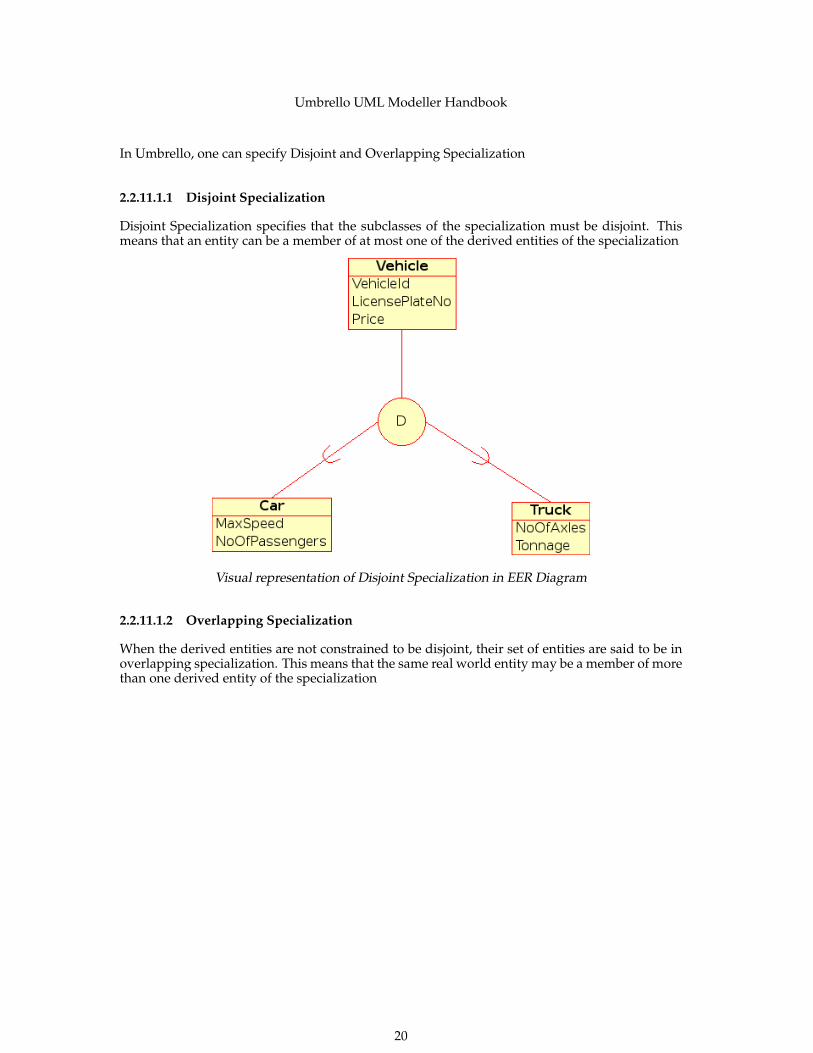
In Umbrello, one can specify Disjoint and Overlapping Specialization
2.2.11.1.1 Disjoint Specialization
Disjoint Specialization specifies that the subclasses of the specialization must be disjoint. Thismeans that an entity can be a member of at most one of the derived entities of the specialization
Visual representation of Disjoint Specialization in EER Diagram
2.2.11.1.2 Overlapping Specialization
When the derived entities are not constrained to be disjoint, their set of entities are said to be inoverlapping specialization. This means that the same real world entity may be a member of morethan one derived entity of the specialization
20

Umbrello UML Modeller Handbook
Visual representation of Overlapping Specialization in EER Diagram
2.2.11.1.3 Category
A derived Entity is said to be a Category when it represents a collection of objects that is a subsetof Union of the distinct entity types. A Category is modelled when the need arises for a single su-perclass/subclass relationship with more than one superclass, where the superclasses representdifferent entity types. ( Much like multiple inheritance in Object Oriented Programming ).
Visual representation of a Category in EER Diagram
21

Umbrello UML Modeller Handbook
Chapter 3
Working with Umbrello UMLModeller
This chapter will introduce you to Umbrello UML Modeller’s user interface and will tell you allyou need to know to start modelling. All actions in Umbrello UML Modeller are accessible viathe menu and the toolbars, but Umbrello UML Modeller also makes extensive use of right mousebutton context menus. You can right mouse button click on almost any element in UmbrelloUML Modeller’s work area or tree view to get a menu with the most useful functions that can beapplied to the particular element you are working on. Some users find this a little confusing atthe beginning because they are more used to working with the menu or tool bars, but once youget used to right clicking it will greatly speed up your work.
3.1 User Interface
Umbrello UML Modeller’s main window is divided in three areas that will help you keep anoverview of your entire system and access the different diagrams quickly while working on yourmodel.These areas are called:
• Tree View
• Work Area
• Documentation and Command history Window
22

Umbrello UML Modeller Handbook
Umbrello UML Modeller’s User Interface
3.1.1 Tree View
The Tree View is usually located on the top left hand side of the window and shows the all thediagrams, classes, actors and use cases that build up your model. The Tree View allows you tohave a quick overview of the elements composing your model. The Tree View also gives you aquick way to switch between the different diagrams in your model and inserting elements fromyour model into the current diagram.
If you are working on a model with more than just a few classes and diagrams, the Tree Viewmay help you stay on top of things by organizing your model elements in folders. You can createfolders by selecting the appropriate option from the context menu (right mouse button click onone of the folders in the tree view) and you can organize your elements by moving them to theappropriate folder (drag and drop)
3.1.2 Documentation and Command History Window
The Documentation and Command history Window is the small window located on the left bot-tom of Umbrello UML Modeller, and it gives you a quick preview of the documentation for thecurrently selected item and the command history of your work session. The DocumentationWindow is rather small because it is intended to allow you just a quick pick into the element’sdocumentation and the overview of the command history while taking as little screen space aspossible. If you need to view the documentation in more detail you can always open the item’sproperties.
3.1.3 Work Area
The Work Area is the main window in Umbrello UML Modeller and is where the real actiontakes place. You use the Work Area to edit and view the diagrams in your model. The Work Areashows the currently active diagram. Currently only one diagram can be shown on the Work Areaat any time.
23

Umbrello UML Modeller Handbook
3.2 Creating, Loading and Saving Models
The first thing you need to start doing something useful with Umbrello UML Modeller is to createa model to work on. When you start Umbrello UML Modeller it always loads the last used modelor creates a new, empty model (depending on your preferences set in the configuration dialog).This will allow you to start working right away.
3.2.1 New Model
If at any time you need to create a new model you can do this by selecting the New entry fromthe File menu, or by clicking on the New icon from the application toolbar. If you are currentlyworking on a model which has been modified Umbrello UML Modeller will ask you if it shouldsave your changes before loading the new model.
3.2.2 Save Model
You can save your model at any time by selecting the option Save from the File Menu or byclicking on the Save button from the application toolbar. If you need to save your model under adifferent name you can use the option Save As from the File Menu.
For your convenience Umbrello UML Modeller also offers you the option to automatically saveyour work each certain time period. You can configure if you want this option as well as the timeintervals in the Settings from Umbrello UML Modeller
3.2.3 Load Model
For loading an already existing model you may select the option Open from the File Menu orclick on the Open icon from the application toolbar. The most recently used models are alsoavailable under the submenu Open Recent in the File Menu to speed up access to your mostfrequently used models.
Umbrello UML Modeller can only work on one model at a time, so if you ask the program toload a model for you and your current model has been modified since the last time you save it,Umbrello UML Modeller will ask you whether your changes should be saved to prevent any lossof work. You can start two or more instances of Umbrello UML Modeller at any one time, youcan also copy and paste between instances.
3.3 Editing Models
In Umbrello UML Modeller, there are basically two ways for editing the elements in your model.
• Edit model elements directly through the Tree View
• Edit model elements through a Diagram
Using the context menu of the different items in the Tree View you are able to add, remove, andmodify almost all the elements in your model. Right clicking on the folders in the Tree View willgive you options for creating the different types of diagrams as well as, depending on whetherthe folder is a Use Case View or a Logical View, Actors, Use Cases, Classes, etc.
Once you have added elements to your model you can also edit an element by accessing itsproperties dialog, which you find by selecting the option Properties from the context menu shownwhen right clicking on the items in the Tree View.
You can also edit your model by creating or modifying elements through diagrams. More detailson how to do this are given in the following sections.
24

Umbrello UML Modeller Handbook
3.4 Adding and Removing Diagrams
Your UML model consists of a set of UML elements and associations between them. Howeveryou cannot see the model directly, you use Diagrams to look at it.
3.4.1 Creating Diagrams
To create a new diagram in your model simply select the diagram type you need from the Newsubmenu in the Diagram menu and give a name to it. The diagram will be created and madeactive, and you will immediately see it in the tree view.
Remember that Umbrello UML Modeller makes extensive use of context menus: you can alsoright mouse button click on a folder in the Tree View and select the appropriate diagram typefrom the New submenu in the context menu. Note that you can create Use Case Diagrams onlyin Use Case View folders, and the other types of diagram can only be created in the Logical Viewfolders.
3.4.2 Removing Diagrams
Should you need to remove a diagram from your model, you can do this by making it active andselecting Delete from the Diagram Menu. You can also achieve this by selecting Delete from thediagrams context menu in the Tree View
Since deleting a diagram is something serious that could cause loss of work if done by accident,Umbrello UML Modeller will ask you to confirm the delete operation before actually removingthe Diagram. Once a diagram has been deleted and the file has been saved there is no way toundo this action.
3.4.3 Renaming Diagrams
If you want to change the name of an existing diagram you can easily do this by selecting theRename option from its right mouse button menu in the Tree View.
Another way to rename a diagram is to do this via its properties dialog, which you obtain byselecting Properties from its Context Menu or by double clicking on it in the Tree View.
3.5 Editing Diagrams
When working on a diagram, Umbrello UML Modeller will try to guide you by applying somesimple rules as to which elements are valid in the different types of diagrams, as well as therelationships that can exist between them. If you are an UML expert you will probably not evennotice it, but this will help UML novices create standard-conformant diagrams.
Once you have created your diagrams it is time to start editing them. Here you should notice the(for beginners subtle) difference between editing your diagram, and editing the model. As youalready know, Diagrams are views of your model. For example, if you create a class by editinga Class Diagram, you are really editing both, your Diagram and your model. If you change thecolor or other display options of a Class in your Class Diagram, you are only editing the Diagram,but nothing is changed in your model.
25
Umbrello UML Modeller Handbook
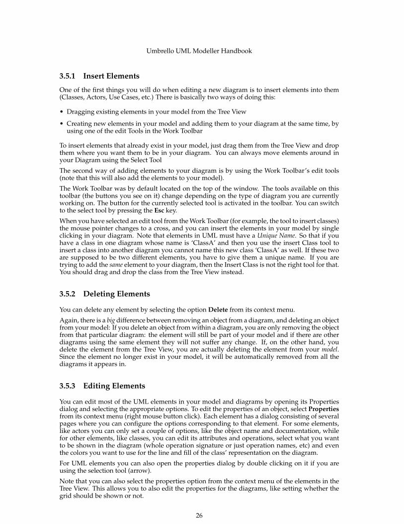
3.5.1 Insert Elements
One of the first things you will do when editing a new diagram is to insert elements into them(Classes, Actors, Use Cases, etc.) There is basically two ways of doing this:
• Dragging existing elements in your model from the Tree View
• Creating new elements in your model and adding them to your diagram at the same time, byusing one of the edit Tools in the Work Toolbar
To insert elements that already exist in your model, just drag them from the Tree View and dropthem where you want them to be in your diagram. You can always move elements around inyour Diagram using the Select Tool
The second way of adding elements to your diagram is by using the Work Toolbar’s edit tools(note that this will also add the elements to your model).
The Work Toolbar was by default located on the top of the window. The tools available on thistoolbar (the buttons you see on it) change depending on the type of diagram you are currentlyworking on. The button for the currently selected tool is activated in the toolbar. You can switchto the select tool by pressing the Esc key.
When you have selected an edit tool from the Work Toolbar (for example, the tool to insert classes)the mouse pointer changes to a cross, and you can insert the elements in your model by singleclicking in your diagram. Note that elements in UML must have a Unique Name. So that if youhave a class in one diagram whose name is ‘ClassA’ and then you use the insert Class tool toinsert a class into another diagram you cannot name this new class ‘ClassA’ as well. If these twoare supposed to be two different elements, you have to give them a unique name. If you aretrying to add the same element to your diagram, then the Insert Class is not the right tool for that.You should drag and drop the class from the Tree View instead.
3.5.2 Deleting Elements
You can delete any element by selecting the option Delete from its context menu.
Again, there is a big difference between removing an object from a diagram, and deleting an objectfrom your model: If you delete an object from within a diagram, you are only removing the objectfrom that particular diagram: the element will still be part of your model and if there are otherdiagrams using the same element they will not suffer any change. If, on the other hand, youdelete the element from the Tree View, you are actually deleting the element from your model.Since the element no longer exist in your model, it will be automatically removed from all thediagrams it appears in.
3.5.3 Editing Elements
You can edit most of the UML elements in your model and diagrams by opening its Propertiesdialog and selecting the appropriate options. To edit the properties of an object, select Propertiesfrom its context menu (right mouse button click). Each element has a dialog consisting of severalpages where you can configure the options corresponding to that element. For some elements,like actors you can only set a couple of options, like the object name and documentation, whilefor other elements, like classes, you can edit its attributes and operations, select what you wantto be shown in the diagram (whole operation signature or just operation names, etc) and eventhe colors you want to use for the line and fill of the class’ representation on the diagram.
For UML elements you can also open the properties dialog by double clicking on it if you areusing the selection tool (arrow).
Note that you can also select the properties option from the context menu of the elements in theTree View. This allows you to also edit the properties for the diagrams, like setting whether thegrid should be shown or not.
26

Umbrello UML Modeller Handbook
3.5.4 Editing Classes
Even though editing the properties of all objects was already covered in the previous section,classes deserve a special section because they are a bit more complicated and have more optionsthan most of the other UML elements.In the properties dialog for a class you can set everything, from the color it uses to the operationsand attributes it has.
3.5.4.1 Class General Settings
The General Settings page of the properties dialog is self-explanatory. Here you can change theclass’ name, visibility, documentation, etc. This page is always available.
3.5.4.2 Class Attribute Settings
In the Attributes Settings page you can add, edit, or delete attributes (variables) of the class. Youcan move attributes up and down the list by pressing the arrow button on the side. This page isalways available.
3.5.4.3 Class Operations Settings
Similar to the Attribute Settings Page, in the Operation Settings Page you can add, edit, or removeoperations for your class. When adding or editing an operation, you enter the basic data in theOperation Properties dialog. If you want to add parameters to your operation you need to clickthe New Parameter button, which will show the Parameter Properties dialog. This page is alwaysavailable
3.5.4.4 Class Template Settings
This page allows you to add class templates which are unspecified classes or datatypes. In Java1.5 these will be called Generics.
3.5.4.5 Class Associations Page
The Class Associations page shows all the associations of this class in the current diagram. Dou-ble clicking on an association shows its properties, and depending on the type of association youmay modify some parameters here such as setting multiplicity and Role name. If the associationdoes not allow such options to be modified, the Association Properties dialog is read-only andyou can only modify the documentation associated with this association.
This page is only available if you open the Class Properties from within a diagram. If you selectthe class properties from the context menu in the Tree View this page is not available.
3.5.4.6 Class Display Page
In the Display Options page, you can set what is to be shown in the diagram. A class can beshown as only one rectangle with the class name in it (useful if you have many classes in yourdiagram, or are for the moment not interested in the details of each class) or as complete asshowing packages, stereotypes, and attributes and operations with full signature and visibility
Depending on the amount of information you want to see you can select the corresponding op-tions in this page. The changes you make here are only display options for the diagram. This
27

Umbrello UML Modeller Handbook
means that ‘hiding’ a class’ operations only makes them not to be shown in the diagram, but theoperation are still there as part of your model. This option is only available if you select the classproperties from within a Diagram. If you open the class properties from the Tree View this pageis missing since such Display Options do not make sense in that case
3.5.4.7 Class Style Page
In the Widget Style page you can configure the colors you want for the line and the fill of thewidget. This option obviously makes sense only for classes displayed in diagrams, and is missingif you open the class’ properties dialog from the Tree View.
3.5.5 Associations
Associations relate two UML objects to each other. Normally associations are defined betweentwo classes, but some types of associations can also exists between use cases and actors.
To create an association select the appropriate tool from the Work Toolbar (generic Association,Generalization, Aggregation, etc.) and single click on the first element participating in the asso-ciation and then single click on the second item participating. Note that those are two clicks, oneon each on the objects participating in the association, it is not a drag from one object to the other.
If you try to use an association in a way against the UML specification Umbrello UML Modellerwill refuse to create the association and you will get an error message. This would be the caseif, for example, a Generalization exists from class A to class B and then you try to create anotherGeneralization from Class B to class ARight clicking on an association will show a context menu with the actions you can apply on it.If you need to delete an association simply select the Delete option from this context menu. Youcan also select the Properties option and, depending on the association type edit attributes suchas roles and multiplicity.
3.5.5.1 Anchor Points
Associations are drawn, by default, as a straight line connecting the two objects in the diagram.
You can add anchor points to bend an association by double clicking some where along the asso-ciation line. This will insert an anchor point (displayed as a blue point when the association lineis selected) which you can move around to give shape to the association
If you need to remove an anchor point, double click on it again to remove it
Note that the only way to edit the properties of an association is through the context menu. Ifyou try to double click on it as with other UML objects, this will only insert an anchor point.
3.5.6 Notes, Text and Boxes
Notes, Lines Of Text and Boxes are elements that can be present in any type of diagram and haveno real semantic value, but are very helpful to add extra comments or explanations that can makeyour diagram easier to understand.
To add a Note or a Line Of Text, select the corresponding tool from the Work Toolbar and singleclick on the diagram where you want to put your comment. You can edit the text by opening theelement through its context menu or in the case of notes by double clicking on them as well.
28

Umbrello UML Modeller Handbook
3.5.6.1 Anchors
Anchors are used to link a text note and another UML Element together. For example, you nor-mally use a text note to explain or make some comment about a class or a particular association,in which case you can use the anchor to make it clear that the note ‘belongs’ to that particularelement.To add an anchor between a note and another UML element, use the anchor tool from the worktoolbar. You first need to click on the note and then click on the UML element you want the noteto be linked to.
29

Umbrello UML Modeller Handbook
Chapter 4
Code Import and Code Generation
Umbrello UML Modeller is a UML modelling tool, and as such its main purpose is to help youin the analysis and design of your systems. However, to make the transition between your designand your implementation, Umbrello UML Modeller allows you to generate source code in differentprogramming languages to get you started. Also, if you want to start using UML in an alreadystarted C++ project, Umbrello UML Modeller can help you create a model of your system fromthe source code by analysing your source code and importing the classes found in it.
4.1 Code Generation
Umbrello UML Modeller can generate source code for various programming languages basedon your UML Model to help you get started with the implementation of your project. The codegenerated consists of the class declarations, with their methods and attributes so you can ‘fill inthe blanks’ by providing the functionality of your classes’ operations.
Umbrello UML Modeller 2 comes with code generation support for ActionScript, Ada, C++, C#,D, IDL, Java™, JavaScript, MySQL and Pascal.
4.1.1 Generating Code
In order to generate code with Umbrello UML Modeller, you first need to create or load a Modelcontaining at least one class. When you are ready to start writing some code, select the CodeGeneration Wizard entry from the Code menu to start a wizard which will guide you trough thecode generation process.
The first step is to select the classes for which you want to generate source code. By default allthe classes of your model are selected, and you can remove the ones for which you do not wantto generate code by moving them to the left-hand side list.
The next step of the wizard allows you to modify the parameters the Code Generator uses whilewriting your code. The following options are available:
30

Umbrello UML Modeller Handbook
Options for the Code Generation in Umbrello UML Modeller
4.1.1.1 Generation Options
4.1.1.1.1 Comment Verbosity
The option Write documentation comments even if empty instructs the Code Generator to writecomments of the /** blah */ style even if the comment blocks are empty. If you added documen-tation to your classes, methods or attributes in your Model, the Code Generator will write thesecomments as Doxygen documentation regardless of what you set here, but if you select this op-tion Umbrello UML Modeller will write comment blocks for all classes, methods and attributeseven if there is no documentation in the Model, in which case you should document your classeslater directly in the source code.
Write comments for sections even if section is empty causes Umbrello UML Modeller to writecomments in the source code to delimit the different sections of a class. For example ‘publicmethods’ or ‘Attributes’ before the corresponding sections. If you select this option UmbrelloUML Modeller will write comments for all sections of the class even if the section is empty. Forexample, it would write a comment saying ‘protected methods’ even if there are no protectedmethods in your class.
4.1.1.1.2 Folders
Write all generated files to folder. Here you should select the folder where you want UmbrelloUML Modeller to put the generated sources.
The Include heading files from folder option allows you to insert a heading at the beginningof each generated file. Heading files can contain copyright or licensing information and containvariables that are evaluated at generation time. You can take a look at the template heading filesshipped with Umbrello UML Modeller to see how to use these variables for replacing your nameor the current date at generation time.
31

Umbrello UML Modeller Handbook
4.1.1.1.3 Overwrite Policy
This option tells Umbrello UML Modeller what to do if the file it wants to create already existsin the destination folder. Umbrello UML Modeller cannot modify existing source files, so you haveto choose between overwriting the existing file, skipping the generation of that particular file orletting Umbrello UML Modeller choose a different file name. If you choose the option to use adifferent name, Umbrello UML Modeller will add a suffix to the file name.
4.1.1.1.4 Language
Umbrello UML Modeller will by default generate code in the language you have selected asActive Language, but with the Code Generation Wizard you have the option to change this toanother language.
4.1.1.2 Generation Wizard Generation
The third and last step of the wizard shows the status of the Code Generation process. You needonly to click on the Generate button to get your classes written for you.
Note that the Options you select during the Code Generation Wizard are only valid for the currentgeneration. The next time you run the wizard you will need to re-select all the options (yourheadings folder, overwrite policy, and so on). You can set the defaults used by Umbrello UMLModeller in the Code Generation section of the Umbrello UML Modeller settings, available atSettings → Configure Umbrello UML Modeller...
If you have set your Code Generation options to the right settings and want to generate somecode right away without going through the wizard, you can select the entire Generate All Codefrom the Code menu. This will generate code for all the classes in your Model using the currentsettings (including Output Folder and Overwrite Policy, so use with care).
4.2 Code Import
Umbrello UML Modeller can import source code from your existing projects to help you buildModel of your systems. Umbrello UML Modeller 2 supports ActionScript, Ada, C++, C#, D, IDL,Java™, Javascript, MySQL, and Pascal source code.
To import classes into your Model, select the entry Code Importing Wizard... from the Codemenu. In the file dialog select the files containing class declarations and press Next > then Startimport and Finish. The classes will be imported and you will find them as part of your Modelin the Tree View. Note that Umbrello UML Modeller will not create any kind of Diagram forshowing your classes, they will only be imported into your Model so that you can use them laterin any diagram you want.
32

Umbrello UML Modeller Handbook
Menu for importing source code in Umbrello UML Modeller
33

Umbrello UML Modeller Handbook
Chapter 5
Other Features
5.1 Other Umbrello UML Modeller Features
This chapter will briefly explain some other features Umbrello UML Modeller offers you.
5.1.1 Copying objects as PNG images
Apart from offering you the normal copy, cut and paste functionality that you would expect tocopy objects between different diagrams, Umbrello UML Modeller can copy the objects as PNGpictures so that you can insert them into any other type of document. You do not need to doanything special to use this feature, just select an object from a diagram (Class, Actor, etc.) andcopy it (Ctrl-C, or using the menu), then open a Calligra Words document (or any program intowhich you can paste images) and select Paste. This is a great feature to export parts of yourdiagram as simple pictures.
5.1.2 Exporting to an Image
You can also export a complete diagram as an image. The only thing you need to do is select thediagram you want to export, and then the option Export as Picture... from the Diagram menu.
5.1.3 Printing
Umbrello UML Modeller allows you to print individual diagrams. Press the Print button on theapplication toolbar or selecting the Print option from the File menu will give you a standard KDEPrint dialog from where you can print your diagrams.
5.1.4 Logical Folders
To better organize your model, especially for larger projects, you can create logical folders in theTree View. Just select the option New → Folder from the context menu of the default foldersin the Tree View to create them. Folders can be nested, and you can move objects around bydragging them from one folder and dropping them into another.
34

Umbrello UML Modeller Handbook
Organizing a Model with Logical Folders in Umbrello UML Modeller
35

Umbrello UML Modeller Handbook
Chapter 6
Authors and History
This project was started by Paul Hensgen as one of his University projects. The original name ofthe application was UML Modeller. Paul did all the development until the end of 2001 when theprogram reached version 1.0.
Version 1.0 already offered a lot of functionality, but after the project had been reviewed at Paul’sUniversity, other developers could join and they started making valuable contributions to UMLModeller, like switching from a binary file format to an XML file, support for more types of UMLDiagrams, Code Generation and Code Import just to name a few.
Paul had to retire from the development team in Summer 2002 but, as Free and Open SourceSoftware, the program continues to improve and evolve and is being maintained by a group ofdevelopers from different parts of the world. In September 2002 the project changed its namefrom UML Modeller, to Umbrello UML Modeller. There are several reasons for the change ofnames, the most important ones being that just ‘uml’ — as it was commonly known — wasa much too generic name and caused problems with some distributions. The other importantreason is that the developers think Umbrello is a much cooler name.
The development of Umbrello UML Modeller as well as discussions as to where the programshould head for future versions is open and takes place over the Internet. If you would like tocontribute to the project, please do not hesitate to contact the developers. There are many waysin which you can help Umbrello UML Modeller:
• Reporting bugs or improvements suggestions
• Fixing bugs or adding features
• Writing good documentation or translating it to other languages
• And of course...coding with us!
As you see, there are many ways in which you can contribute. All of them are very importantand everyone is welcome to participate.
The Umbrello UML Modeller developers can be reached at [email protected].
36

Umbrello UML Modeller Handbook
Chapter 7
Copyright
Copyright 2001, Paul Hensgen
Copyright 2002-2014 The Umbrello UML Modeller Authors.
This documentation is licensed under the terms of the GNU Free Documentation License.This program is licensed under the terms of the GNU General Public License.
37