Embed Size (px)
Citation preview
www.contrinex.com 221
InductiveCapacitive
UltrasonicIndex
Glossary
AccessoriesCables &
connectorsO
ptical fibersPhotoelectric
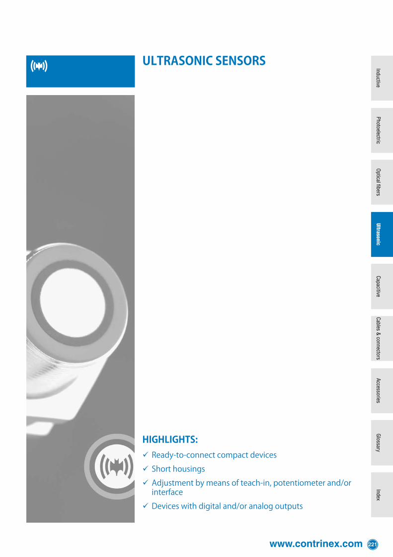
ultrasonic sensors
HigHligHts:ü Ready-to-connectcompactdevices
ü Shorthousings
ü Adjustmentbymeansofteach-in,potentiometerand/orinterface
ü Deviceswithdigitaland/oranalogoutputs
222 Detailed data sheets for these products can be found on the Contrinex website:
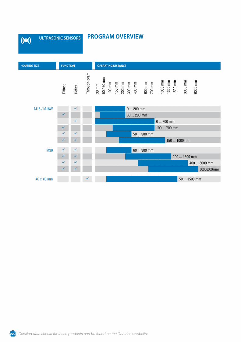
program overview
housing size FunCtion operating distanCeD
iffus
e
Ref
lex
Thro
ugh-
beam
30 m
m
50 /
60 m
m
100
mm
150
mm
200
mm
300
mm
400
mm
600
mm
700
mm
1000
mm
1300
mm
1500
mm
3000
mm
6000
mm
M18 / M18W ü 0 ... 200 mm
ü 30 ... 200 mm
ü 0 ... 700 mm
ü 100 ... 700 mm
ü ü 50 ... 300 mm
ü ü 150 ... 1000 mm
M30 ü ü 60 ... 300 mm
ü ü 200 ... 1300 mm
ü ü 400 ... 3000 mm
ü ü 600...6000 mm
40 x 40 mm ü 50 ... 1500 mm
ultrasonic sensors
www.contrinex.com 223
InductiveCapacitive
UltrasonicIndex
Glossary
AccessoriesCables &
connectorsO
ptical fibersPhotoelectric
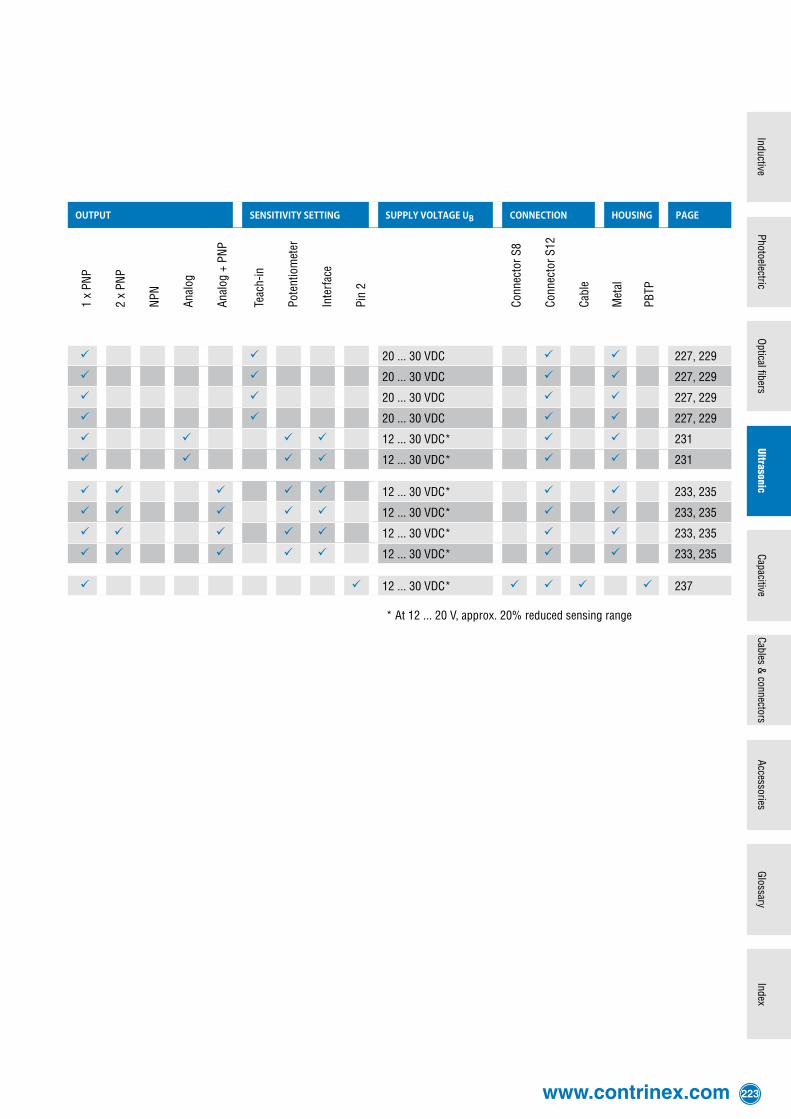
output sensitivity setting supply voltage uB ConneCtion housing page
1 x
PNP
2 x
PNP
NPN
Anal
og
Anal
og +
PN
P
Teac
h-in
Pote
ntio
met
er
Inte
rfac
e
Pin
2
Conn
ecto
r S8
Conn
ecto
r S12
Cabl
e
Met
al
PBTP
ü ü 20 ... 30 VDC ü ü 227, 229
ü ü 20 ... 30 VDC ü ü 227, 229
ü ü 20 ... 30 VDC ü ü 227, 229
ü ü 20 ... 30 VDC ü ü 227, 229
ü ü ü ü 12 ... 30 VDC* ü ü 231
ü ü ü ü 12 ... 30 VDC* ü ü 231
ü ü ü ü ü 12 ... 30 VDC* ü ü 233, 235
ü ü ü ü ü 12 ... 30 VDC* ü ü 233, 235
ü ü ü ü ü 12 ... 30 VDC* ü ü 233, 235
ü ü ü ü ü 12 ... 30 VDC* ü ü 233, 235
ü ü 12 ... 30 VDC* ü ü ü ü 237
* At 12 ... 20 V, approx. 20% reduced sensing range
224 Detailed data sheets for these products can be found on the Contrinex website:
ultrasonic sensors operating principle
Ultrasonic sensors can be used as contact-free devices in many areas of auto-mation. They are employed wherever distances have to be measured in air, since they not only detect objects, but they can also indicate and evaluate the absolute distance between themselves and the target. Changing atmospheric conditions, (e.g. temperature variations) are compensated during evaluation of the measure-ment.Ultrasonic devices working as diffuse or reflex sensors send out ultrasonic im-pulses in cyclical intervals. If these are reflected by an object, the resulting echo is received and converted into an electrical signal. Detection of the received echo is dependent on its intensity, itself dependent on the distance of the object from the sensor. The devices function according to the echo-delay principle, i.e. the time delay between the emitter and echo impulses is evaluated.With ultrasonic devices working as through-beam sensors, on the other hand, the emitter sends out a narrowly focused permanent sound towards the receiver. The latter evaluates the ultrasonic signal and switches the output as soon as the sound is interrupted by an object.
sensing rangeDue to the sensor's construction, the ultrasound is radiated in a lobar shape. Only reflecting objects within this sound beam are detected. Echoes in the blind zone between the sensing face and the sensing range cannot be evaluated.
targetsThe targets to be detected can be in the solid, liquid, granular or powder state. The material may be transparent or colored, of any shape, and with a polished or matt surface. All even or flat surfaces up to an angular deviation of approximately 3° from perpendicular to the sound beam can be detected with certainty, even at the maximum operating distance. Depending on surface roughness, the angular deviation may even be greater. In principle, targets can enter the sound beam from any direction.
temperature compensationThe ultrasonic sensors are equipped with temperature sensors and a compensa-tion circuit, in order to be able to compensate for changes in operating distance caused by temperature fluctuations.
environmental conditionsNormal atmospheric variations at any given location have a negligible influence on the speed of sound. The propagation of ultrasonic waves in a vacuum is not possible.Hot objects (e.g. red-hot metals) cause air turbulence, dispersing or diverting the ultrasound. In such surroundings, no analyzable echo is produced.Ultrasonic sensors are designed for use under normal atmospheric conditions, i.e. in air. Operation in other gases (e.g. carbon dioxide) can give rise to serious error measurements or even functional failure, due to differing sound speed and damp-ing values.Normal rain or snowfall does not impair the functioning of ultrasonic sensors. The transducer surface should, however, not become moistened, although dew is per-missible.Ambient noise is distinguished from the system’s own sound echoes and, as a rule, does not lead to functional errors.
safetyThe use of ultrasonic sensors in applications where the safety of people is depend-ent on their functioning is not permitted.
www.contrinex.com 225
InductiveCapacitive
UltrasonicIndex
Glossary
AccessoriesCables &
connectorsO
ptical fibersPhotoelectric
available models
synchronization
programming
mounting
Ultrasonic sensors from Contrinex are available as diffuse, reflex and through-beam types.
diffuse sensorsWith diffuse sensors, the target func-tions as a reflector. As soon as an object enters the preset sensing area, its echo causes the device to switch.
reflex sensorsIn the case of reflex sensors, a fixed reflector (e.g. a small metal plate) is mounted facing the device. The switch-ing range is set to this reflector. If an object comes between the ultrasonic sensor and the reflector, the sensor no longer recognizes the latter, which caus-es the output to switch.
tHrougH-beam sensorsThrough-beam sensors consist of an emitter and a receiver placed opposite each other. If an object comes between them, the sound is interrupted, causing the output to switch.
Devices of ser ies 1180/1181 and 1300...1303 can be synchronized with each other by simply connecting their synchronization outputs (pin 2 for N.O., pin 4 for N.C.). In this way, up to 10 sensors can be synchronized. In many cases, it is thus possible to mount the sensors very close to one another with-out mutual interference.The fourth connection can be used as an external release input. Thus, ultra-sonic sensors can be activated or de-activated with an external control, with-out switching the supply voltage on and off. An external multiplex operation can be achieved by switching the ultrasonic sensors on and off one after the other via the release input. In this case, assur-ance is always given that the ultrasonic sensors do not influence one another. As opposed to internal synchronization, where more than 10 switches can be operated.
For optimum adaptation to the application conditions, devices of series 1180/1181 and 1300 ... 1303 can be programmed with the PC interface device APE-0000-001 (see Ultrasonic accessories, page 238).The series 1180/1181C and 1180/1181W devices are adjustable by teach-in via the device connection.The sensitivity of series 4040 devices can be adjusted via pin 2 or the white cable wire of the receiver.
Ultrasonic sensors can be operated in any installation position. However, posi-tions in which materials can be deposited on the transducer surface should be avoided.In order to obtain the best reflection results, the ultrasonic sensor should be ori-ented in such a way that the sound waves strike the target at as close to 90° as possible. If this is not possible (e.g. with bulk materials), the maximum possible range has to be determined experimentally, and is dependent on the material, surface and orientation of the objects.
226 Detailed data sheets for these products can be found on the Contrinex website:
main features− Ready-to-connect compact devices− Short cylindrical housings of 63.5 mm− High excess gain, therefore insensitive to dirt and ambient noise− Detection independent of target's color, shape, material and surface structure− Reduced blind zone− Low current drain− Adjustment by means of external teach-in− Diffuse sensors feature background suppression
ledThe yellow LED lights up when the output is switched. In teach mode, the LED flashes.
connectionDevices with 4-pole S12 connector are standard.
technical data
(according to IEC 60947-5-2)
Housing material Nickel-plated brass
Supply voltage range UB 20 ... 30 VDC
Max. ripple content ≤10 %
Output current ≤ 150 mA
Output voltage drop ≤ 2.0 V at 150 mA
Ambient temperature range -25 ... +70 °C
Degree of protection IP 67
EMC protection:
IEC 61000-4-2 4 kV
IEC 61000-4-3 10 V/m
IEC 61000-4-4 2 kV
IEC 61000-4-6 10 V
EN 55011 Class B
Short-circuit protection Built-in
Polarity reversal protection Built-in
Power-on reset Built-in
ultrasonic sensors
www.contrinex.com 227
InductiveCapacitive
UltrasonicIndex
Glossary
AccessoriesCables &
connectorsO
ptical fibersPhotoelectric
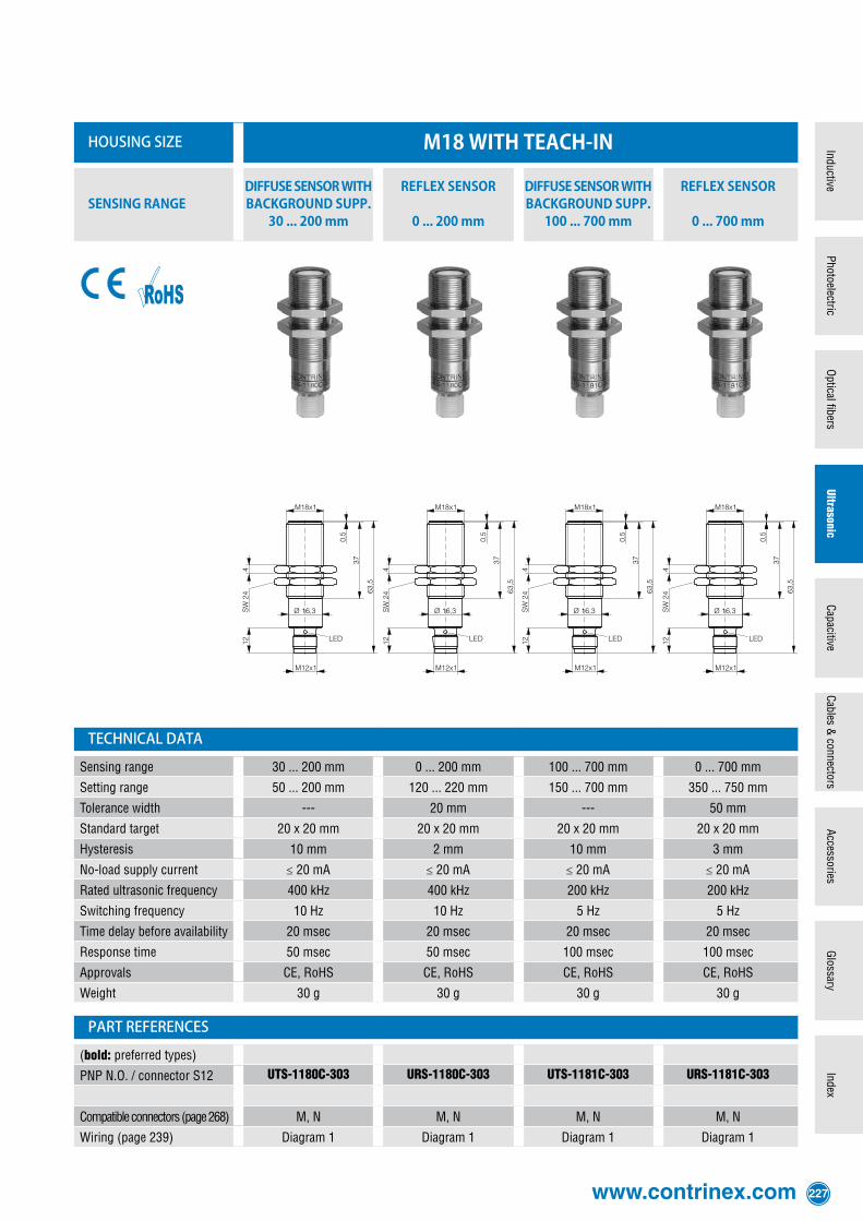
housing size m18 with teaCh-in
sensing range diffuse sensor witH background supp.
30 ... 200 mm
reflex sensor
0 ... 200 mm
diffuse sensor witH background supp.
100 ... 700 mm
reflex sensor
0 ... 700 mm
technical data
Sensing range 30 ... 200 mm 0 ... 200 mm 100 ... 700 mm 0 ... 700 mm
Setting range 50 ... 200 mm 120 ... 220 mm 150 ... 700 mm 350 ... 750 mm
Tolerance width --- 20 mm --- 50 mm
Standard target 20 x 20 mm 20 x 20 mm 20 x 20 mm 20 x 20 mm
Hysteresis 10 mm 2 mm 10 mm 3 mm
No-load supply current ≤ 20 mA ≤ 20 mA ≤ 20 mA ≤ 20 mA
Rated ultrasonic frequency 400 kHz 400 kHz 200 kHz 200 kHz
Switching frequency 10 Hz 10 Hz 5 Hz 5 Hz
Time delay before availability 20 msec 20 msec 20 msec 20 msec
Response time 50 msec 50 msec 100 msec 100 msec
Approvals CE, RoHS CE, RoHS CE, RoHS CE, RoHS
Weight 30 g 30 g 30 g 30 g
part references
(bold: preferred types)
PNP N.O. / connector S12 UTS-1180C-303 URS-1180C-303 UTS-1181C-303 URS-1181C-303
Compatible connectors (page 268) M, N M, N M, N M, N
Wiring (page 239) Diagram 1 Diagram 1 Diagram 1 Diagram 1
228 Detailed data sheets for these products can be found on the Contrinex website:
main features− Ready-to-connect compact devices− Lateral sensing− Robust and fully integrated sensing head− High excess gain, therefore insensitive to dirt and ambient noise− Detection independent of target's color, shape, material and surface structure− Reduced blind zone− Low current drain− Adjustment by means of external teach-in− Diffuse sensors feature background suppression
ledThe yellow LED lights up when the output is switched. In teach mode, the LED flashes.
connectionDevices with 4-pole S12 connector are standard.
technical data
(according to IEC 60947-5-2)
Housing material Nickel-plated brass
Supply voltage range UB 20 ... 30 VDC
Max. ripple content ≤10 %
Output current ≤ 150 mA
Output voltage drop ≤ 2.0 V at 150 mA
Ambient temperature range -25 ... +70 °C
Degree of protection IP 67
EMC protection:
IEC 61000-4-2 4 kV
IEC 61000-4-3 10 V/m
IEC 61000-4-4 2 kV
IEC 61000-4-6 10 V
EN 55011 Class B
Short-circuit protection Built-in
Polarity reversal protection Built-in
Power-on reset Built-in
ultrasonic sensors
www.contrinex.com 229
InductiveCapacitive
UltrasonicIndex
Glossary
AccessoriesCables &
connectorsO
ptical fibersPhotoelectric
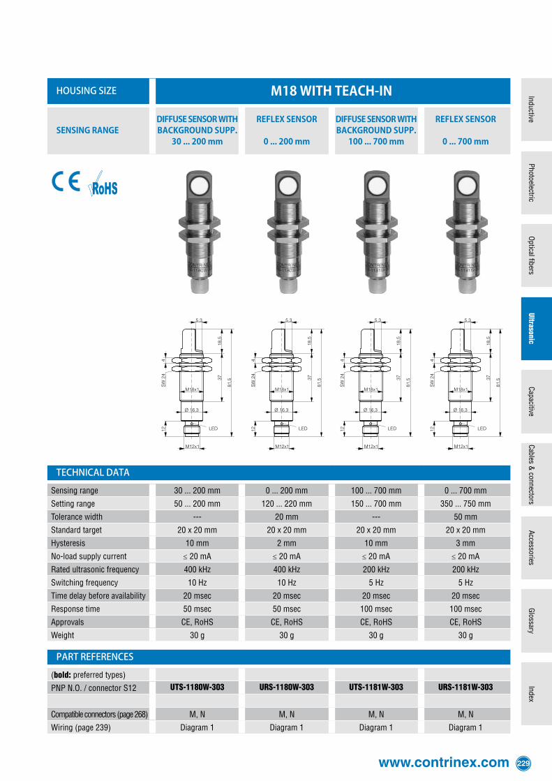
housing size m18 with teaCh-in
sensing range diffuse sensor witH background supp.
30 ... 200 mm
reflex sensor
0 ... 200 mm
diffuse sensor witH background supp.
100 ... 700 mm
reflex sensor
0 ... 700 mm
technical data
Sensing range 30 ... 200 mm 0 ... 200 mm 100 ... 700 mm 0 ... 700 mm
Setting range 50 ... 200 mm 120 ... 220 mm 150 ... 700 mm 350 ... 750 mm
Tolerance width --- 20 mm --- 50 mm
Standard target 20 x 20 mm 20 x 20 mm 20 x 20 mm 20 x 20 mm
Hysteresis 10 mm 2 mm 10 mm 3 mm
No-load supply current ≤ 20 mA ≤ 20 mA ≤ 20 mA ≤ 20 mA
Rated ultrasonic frequency 400 kHz 400 kHz 200 kHz 200 kHz
Switching frequency 10 Hz 10 Hz 5 Hz 5 Hz
Time delay before availability 20 msec 20 msec 20 msec 20 msec
Response time 50 msec 50 msec 100 msec 100 msec
Approvals CE, RoHS CE, RoHS CE, RoHS CE, RoHS
Weight 30 g 30 g 30 g 30 g
part references
(bold: preferred types)
PNP N.O. / connector S12 UTS-1180W-303 URS-1180W-303 UTS-1181W-303 URS-1181W-303
Compatible connectors (page 268) M, N M, N M, N M, N
Wiring (page 239) Diagram 1 Diagram 1 Diagram 1 Diagram 1

230 Detailed data sheets for these products can be found on the Contrinex website:
main features− Ready-to-connect compact devices− Can be operated as diffuse or reflex sensors (with interface)− High excess gain, therefore insensitive to dirt and ambient noise− Detection independent of target's color, shape, material and surface structure− Reduced blind zone− Low current drain− Adjustment by means of potentiometer (only devices with switching output) and
interface device APE-0000-001− Switching or analog output− Fore- and background suppression− Diffuse sensors with window function
ledThe yellow LED lights up when the output is switched. Flashing LED indicates misadjustment.
connectionDevices with 4-pole S12 connector are standard.
technical data
(according to IEC 60947-5-2)
Housing material Nickel-plated brass
Supply voltage range UB 12 ... 30 VDC*
Max. ripple content ≤10 %
Output current ≤ 150 mA (devices with switchig output)
Output voltage drop ≤ 3.0 V at 150 mA
Ambient temperature range -25 ... +70 °C
Degree of protection IP 67
EMC protection:
IEC 61000-4-2 4 kV
IEC 61000-4-3 10 V/m
IEC 61000-4-4 2 kV
IEC 61000-4-6 10 V
EN 55011 Class B
Short-circuit protection Built-in
Polarity reversal protection Built-in
Power-on reset Built-in
** At 12 ... 20 V, approx. 20% reduced sensing range.
ultrasonic sensors
www.contrinex.com 231
InductiveCapacitive
UltrasonicIndex
Glossary
AccessoriesCables &
connectorsO
ptical fibersPhotoelectric
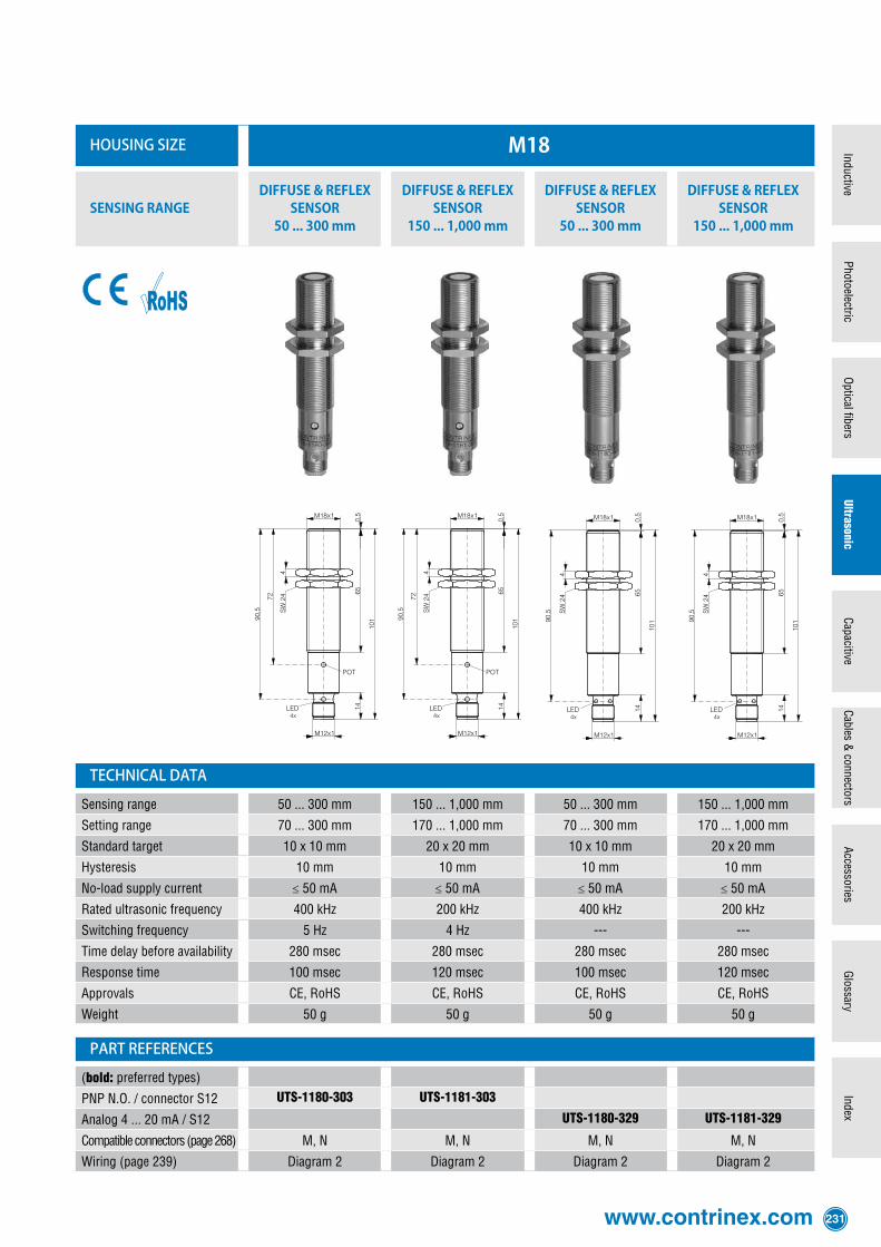
housing size m18
sensing rangediffuse & reflex
sensor50 ... 300 mm
diffuse & reflex sensor
150 ... 1,000 mm
diffuse & reflex sensor
50 ... 300 mm
diffuse & reflex sensor
150 ... 1,000 mm
technical data
Sensing range 50 ... 300 mm 150 ... 1,000 mm 50 ... 300 mm 150 ... 1,000 mm
Setting range 70 ... 300 mm 170 ... 1,000 mm 70 ... 300 mm 170 ... 1,000 mm
Standard target 10 x 10 mm 20 x 20 mm 10 x 10 mm 20 x 20 mm
Hysteresis 10 mm 10 mm 10 mm 10 mm
No-load supply current ≤ 50 mA ≤ 50 mA ≤ 50 mA ≤ 50 mA
Rated ultrasonic frequency 400 kHz 200 kHz 400 kHz 200 kHz
Switching frequency 5 Hz 4 Hz --- ---
Time delay before availability 280 msec 280 msec 280 msec 280 msec
Response time 100 msec 120 msec 100 msec 120 msec
Approvals CE, RoHS CE, RoHS CE, RoHS CE, RoHS
Weight 50 g 50 g 50 g 50 g
part references
(bold: preferred types)
PNP N.O. / connector S12 UTS-1180-303 UTS-1181-303
Analog 4 ... 20 mA / S12 UTS-1180-329 UTS-1181-329
Compatible connectors (page 268) M, N M, N M, N M, N
Wiring (page 239) Diagram 2 Diagram 2 Diagram 2 Diagram 2
232 Detailed data sheets for these products can be found on the Contrinex website:
main features− Ready-to-connect compact devices− Can be operated as diffuse or reflex sensors− High excess gain, therefore insensitive to dirt and ambient noise− Detection independent of target's color, shape, material and surface structure− Reduced blind zone− Low current drain− Adjustment by means of potentiometer and interface device APE-0000-001− 1 or 2 switching outputs− Fore- and background suppression− Diffuse sensors with window function
ledThe yellow LED lights up when the output is switched. Flashing LED indicates misadjustment.
connectionDevices with 4-pole (UTS-130#-303) or 5-pole (UTS-130#-107) S12 connector are standard.
technical data
(according to IEC 60947-5-2)
Housing material Nickel-plated brass
Supply voltage range UB 12 ... 30 VDC*
Max. ripple content ≤10 %
Output current ≤ 300 mA
Output voltage drop ≤ 3.0 V at 300 mA
Ambient temperature range -25 ... +70 °C
Degree of protection IP 65
EMC protection:
IEC 61000-4-2 4 kV
IEC 61000-4-3 10 V/m
IEC 61000-4-4 2 kV
IEC 61000-4-6 10 V
EN 55011 Class B
Short-circuit protection Built-in
Polarity reversal protection Built-in
Power-on reset Built-in
* At 12 ... 20 V, approx. 20% reduced sensing range.
ultrasonic sensors
www.contrinex.com 233
InductiveCapacitive
UltrasonicIndex
Glossary
AccessoriesCables &
connectorsO
ptical fibersPhotoelectric
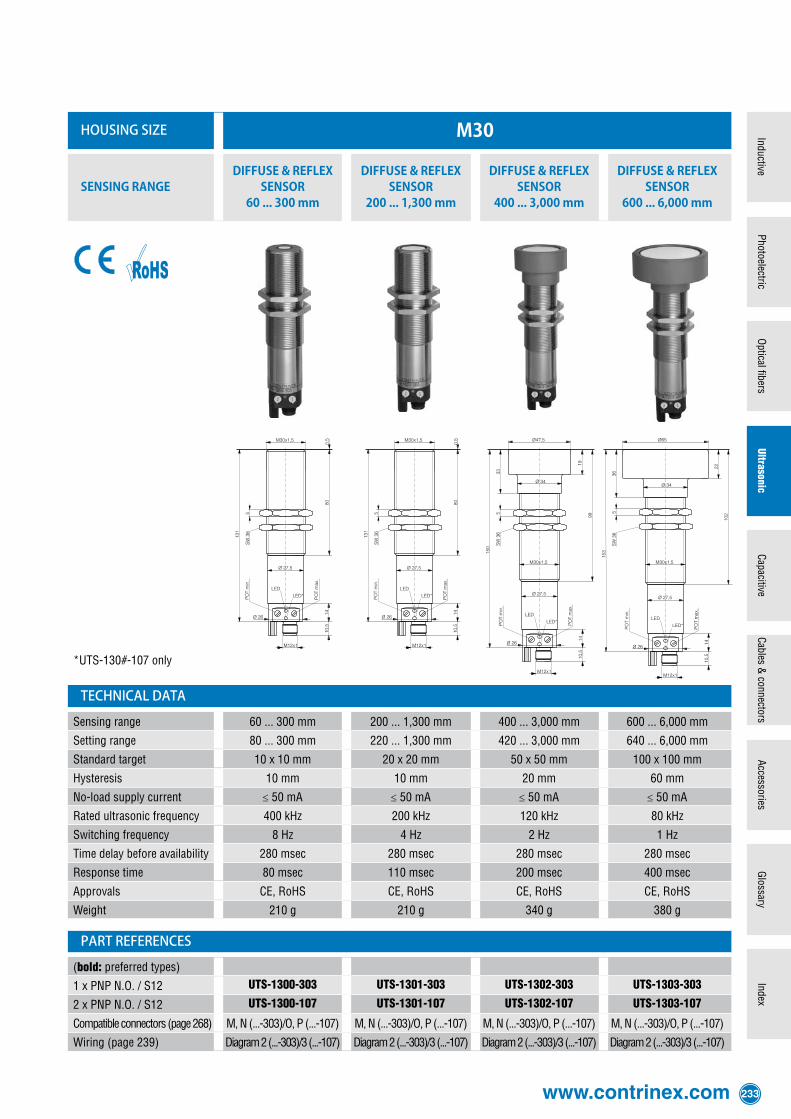
housing size m30
sensing rangediffuse & reflex
sensor60 ... 300 mm
diffuse & reflex sensor
200 ... 1,300 mm
diffuse & reflex sensor
400 ... 3,000 mm
diffuse & reflex sensor
600 ... 6,000 mm
*UTS-130#-107 only
technical data
Sensing range 60 ... 300 mm 200 ... 1,300 mm 400 ... 3,000 mm 600 ... 6,000 mm
Setting range 80 ... 300 mm 220 ... 1,300 mm 420 ... 3,000 mm 640 ... 6,000 mm
Standard target 10 x 10 mm 20 x 20 mm 50 x 50 mm 100 x 100 mm
Hysteresis 10 mm 10 mm 20 mm 60 mm
No-load supply current ≤ 50 mA ≤ 50 mA ≤ 50 mA ≤ 50 mA
Rated ultrasonic frequency 400 kHz 200 kHz 120 kHz 80 kHz
Switching frequency 8 Hz 4 Hz 2 Hz 1 Hz
Time delay before availability 280 msec 280 msec 280 msec 280 msec
Response time 80 msec 110 msec 200 msec 400 msec
Approvals CE, RoHS CE, RoHS CE, RoHS CE, RoHS
Weight 210 g 210 g 340 g 380 g
part references
(bold: preferred types)
1 x PNP N.O. / S12 UTS-1300-303 UTS-1301-303 UTS-1302-303 UTS-1303-303
2 x PNP N.O. / S12 UTS-1300-107 UTS-1301-107 UTS-1302-107 UTS-1303-107
Compatible connectors (page 268) M, N (...-303)/O, P (...-107) M, N (...-303)/O, P (...-107) M, N (...-303)/O, P (...-107) M, N (...-303)/O, P (...-107)
Wiring (page 239) Diagram 2 (...-303)/3 (...-107) Diagram 2 (...-303)/3 (...-107) Diagram 2 (...-303)/3 (...-107) Diagram 2 (...-303)/3 (...-107)
234 Detailed data sheets for these products can be found on the Contrinex website:
main features− Ready-to-connect compact devices− Can be operated as diffuse or reflex sensors− High excess gain, therefore insensitive to dirt and ambient noise− Detection independent of target's color, shape, material and surface structure− Reduced blind zone− Low current drain− Adjustment by means of potentiometer and interface device APE-0000-001− Switching and analog outputs− Fore- and background suppression− Diffuse sensors with window function
ledThe yellow LED lights up when the output is switched. Flashing LED indicates misadjustment.
connectionDevices with 5-pole S12 connector are standard.
technical data
(according to IEC 60947-5-2)
Housing material Nickel-plated brass
Supply voltage range UB 12 ... 30 VDC*
Max. ripple content ≤10 %
Output current ≤ 300 mA
Output voltage drop ≤ 3.0 V at 300 mA
Ambient temperature range -25 ... +70 °C
Degree of protection IP 65
EMC protection:
IEC 61000-4-2 4 kV
IEC 61000-4-3 10 V/m
IEC 61000-4-4 2 kV
IEC 61000-4-6 10 V
EN 55011 Class B
Short-circuit protection Built-in
Polarity reversal protection Built-in
Power-on reset Built-in
* At 12 ... 20 V, approx. 20% reduced sensing range.
ultrasonic sensors

www.contrinex.com 235
InductiveCapacitive
UltrasonicIndex
Glossary
AccessoriesCables &
connectorsO
ptical fibersPhotoelectric
housing size m30 with analog output
sensing rangediffuse & reflex
sensor60 ... 300 mm
diffuse & reflex sensor
200 ... 1,300 mm
diffuse & reflex sensor
400 ... 3,000 mm
diffuse & reflex sensor
600 ... 6,000 mm
technical data
Sensing range 60 ... 300 mm 200 ... 1,300 mm 400 ... 3,000 mm 600 ... 6,000 mm
Setting range 80 ... 300 mm 220 ... 1,300 mm 420 ... 3,000 mm 640 ... 6,000 mm
Standard target 10 x 10 mm 20 x 20 mm 50 x 50 mm 100 x 100 mm
Hysteresis 10 mm 10 mm 20 mm 60 mm
No-load supply current ≤ 60 mA ≤ 60 mA ≤ 60 mA ≤ 60 mA
Rated ultrasonic frequency 400 kHz 200 kHz 120 kHz 80 kHz
Switching frequency 5 Hz 4 Hz 2 Hz 1 Hz
Time delay before availability 280 msec 280 msec 280 msec 280 msec
Response time 100 msec 120 msec 200 msec 400 msec
Approvals CE, RoHS CE, RoHS CE, RoHS CE, RoHS
Weight 210 g 210 g 340 g 380 g
part references
(bold: preferred types)
Analog 4...20 mA+PNP N.O./S12 UTS-1300-123 UTS-1301-123 UTS-1302-123 UTS-1303-123
Analog 0...10 V+PNP N.O./S12 UTS-1300-113 UTS-1301-113 UTS-1302-113 UTS-1303-113
Compatible connectors (page 268) O, P O, P O, P O, P
Wiring (page 239) Diagram 4 (...-123)/5 (...-113) Diagram 4 (...-123)/5 (...-113) Diagram 4 (...-123)/5 (...-113) Diagram 4 (...-123)/5 (...-113)

236 Detailed data sheets for these products can be found on the Contrinex website:
main features− Ready-to-connect compact devices− High excess gain, therefore insensitive to dirt and ambient noise− Detection independent of target's color, shape, material and surface structure− High switching frequency− Narrowly focused permanent sound emission− No blind zone− Low current drain− Sensitivity adjustment via pin 2 or white cable wire of receiver
ledThe yellow LED lights up when the output is switched, the green LED lights up as soon as the sensor is connected.
connectionDevices with 4-pole S12 or S8 connector, or 3 m PUR cable are standard.
technical data
(according to IEC 60947-5-2)
Housing material Glass-fiber reinforced PBTP (Crastin)
Supply voltage range UB 12 ... 30 VDC*
Max. ripple content ≤10 %
Output current ≤ 100 mA
Output voltage drop ≤ 2.0 V at 100 mA
Ambient temperature range 0 ... +70 °C
Degree of protection IP 67
EMC protection:
IEC 60947-5-2 (7.2.3.1) 1 kV
IEC 61000-4-2 4 kV / 8 kV
IEC 61000-4-3 10 V/m
IEC 61000-4-4 2 kV
IEC 61000-4-6 7 V
Short-circuit protection Built-in
Polarity reversal protection Built-in
* At 12 ... 20 V, approx. 20% reduced sensitivity.
ultrasonic sensors
www.contrinex.com 237
InductiveCapacitive
UltrasonicIndex
Glossary
AccessoriesCables &
connectorsO
ptical fibersPhotoelectric
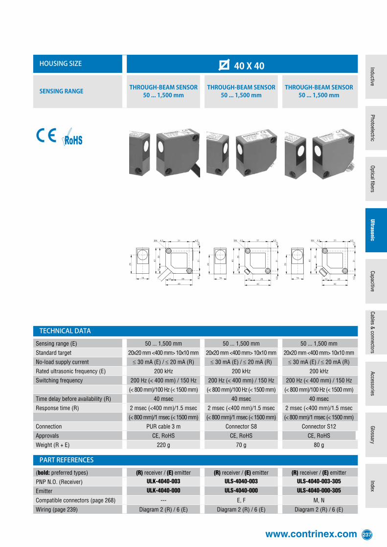
housing size 40 x 40
sensing range tHrougH-beam sensor50 ... 1,500 mm
tHrougH-beam sensor50 ... 1,500 mm
tHrougH-beam sensor50 ... 1,500 mm
technical data
Sensing range (E) 50 ... 1,500 mm 50 ... 1,500 mm 50 ... 1,500 mm
Standard target 20x20 mm <400 mm> 10x10 mm 20x20 mm <400 mm> 10x10 mm 20x20 mm <400 mm> 10x10 mm
No-load supply current ≤30 mA (E) / ≤20 mA (R) ≤30 mA (E) / ≤20 mA (R) ≤30 mA (E) / ≤20 mA (R)
Rated ultrasonic frequency (E) 200 kHz 200 kHz 200 kHz
Switching frequency 200 Hz (< 400 mm) / 150 Hz 200 Hz (< 400 mm) / 150 Hz 200 Hz (< 400 mm) / 150 Hz
(< 800 mm)/100 Hz (< 1500 mm) (< 800 mm)/100 Hz (< 1500 mm) (< 800 mm)/100 Hz (< 1500 mm)
Time delay before availability (R) 40 msec 40 msec 40 msec
Response time (R) 2 msec (<400 mm)/1.5 msec 2 msec (<400 mm)/1.5 msec 2 msec (<400 mm)/1.5 msec
(< 800 mm)/1 msec (< 1500 mm) (< 800 mm)/1 msec (< 1500 mm) (< 800 mm)/1 msec (< 1500 mm)
Connection PUR cable 3 m Connector S8 Connector S12
Approvals CE, RoHS CE, RoHS CE, RoHS
Weight (R + E) 220 g 70 g 80 g
part references
(bold: preferred types) (R) receiver / (E) emitter (R) receiver / (E) emitter (R) receiver / (E) emitter
PNP N.O. (Receiver) ULK-4040-003 ULS-4040-003 ULS-4040-003-305
Emitter ULK-4040-000 ULS-4040-000 ULS-4040-000-305
Compatible connectors (page 268) --- E, F M, N
Wiring (page 239) Diagram 2 (R) / 6 (E) Diagram 2 (R) / 6 (E) Diagram 2 (R) / 6 (E)
238 Detailed data sheets for these products can be found on the Contrinex website:
ultrasonic accessories
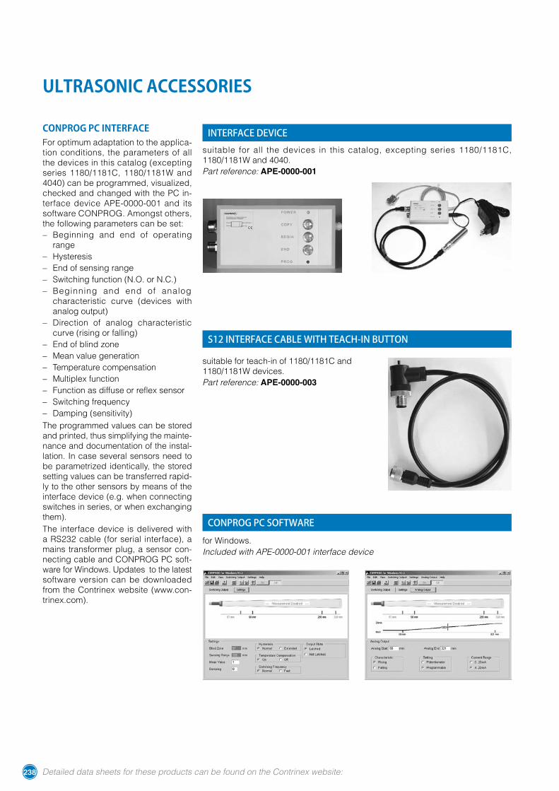
conprog pc interfaceFor optimum adaptation to the applica-tion conditions, the parameters of all the devices in this catalog (excepting series 1180/1181C, 1180/1181W and 4040) can be programmed, visualized, checked and changed with the PC in-terface device APE-0000-001 and its software CONPROG. Amongst others, the following parameters can be set:− Beginning and end of operating
range− Hysteresis− End of sensing range− Switching function (N.O. or N.C.)− Beginning and end of analog
characteristic curve (devices with analog output)
− Direction of analog characteristic curve (rising or falling)
− End of blind zone− Mean value generation− Temperature compensation− Multiplex function− Function as diffuse or reflex sensor− Switching frequency− Damping (sensitivity)The programmed values can be stored and printed, thus simplifying the mainte-nance and documentation of the instal-lation. In case several sensors need to be parametrized identically, the stored setting values can be transferred rapid-ly to the other sensors by means of the interface device (e.g. when connecting switches in series, or when exchanging them).The interface device is delivered with a RS232 cable (for serial interface), a mains transformer plug, a sensor con-necting cable and CONPROG PC soft-ware for Windows. Updates to the latest software version can be downloaded from the Contrinex website (www.con-trinex.com).
suitable for all the devices in this catalog, excepting series 1180/1181C, 1180/1181W and 4040.Part reference: APE-0000-001
suitable for teach-in of 1180/1181C and 1180/1181W devices.Part reference: APE-0000-003
for Windows.Included with APE-0000-001 interface device
interface device
s12 interface cable with teach-in button
conprog pc software
www.contrinex.com 239
InductiveCapacitive
UltrasonicIndex
Glossary
AccessoriesCables &
connectorsO
ptical fibersPhotoelectric
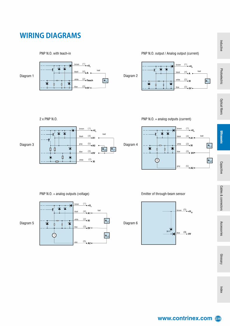
wiring diagrams
Diagram 1
PNP N.O. + analog outputs (voltage)
PNP N.O. with teach-in
PNP N.O. + analog outputs (current)
PNP N.O. output / Analog output (current)
2 x PNP N.O.
Diagram 2
Diagram 3 Diagram 4
Diagram 5
XI
(1)
(4)
(5)
(3)
(2)
Teach
(1)
(4)
(2)
(3)
+U
A
B
R L
0V
(1)
(4)
(2)
(3)
+U
A
XI
B
R L
0V
(1)
(4)
(2)
(3)
+U
XI
B
R
R
A1
A2(5)
0V
(1)
(4)
(2)
(3)
+U
XI
0V
B
R
R
A1
A2(5)
Diagram 6
Emitter of through-beam sensor
brown
black
blue
load
white
brown
black
blue
gray
load
white
brown
black
blue
white
load
gray
brown
black
blue
load
white
brown
black
blue
white
gray
load
brown
blue