Embed Size (px)
Citation preview

UFC 3-600-01 8 August 2016
Change 1, 28 November 2016
UNIFIED FACILITIES CRITERIA (UFC)
APPROVED FOR PUBLIC RELEASE; DISTRIBUTION UNLIMITED
FIRE PROTECTION ENGINEERING
FOR FACILITIES
UFC 3-600-01 8 August 2016
Change 1, 28 November 2016
UNIFIED FACILITIES CRITERIA (UFC)
FIRE PROTECTION ENGINEERING FOR FACILITIES
Any copyrighted material included in this UFC is identified at its point of use. Use of the copyrighted material apart from this UFC must have the permission of the copyright holder. U.S. ARMY CORPS OF ENGINEERS NAVAL FACILITIES ENGINEERING COMMAND (Preparing Activity) AIR FORCE CIVIL ENGINEER CENTER Record of Changes (changes are indicated by \1\ ... /1/) Change No. Date Location 1 28 Nov 2016 Change to definition of ‘AHJ’ (paragraph 2-1.3) required
modifications to paragraphs 1-7.2.2, 1-9, 9-16.1, and 9-18.5.1. Change to paragraph 9-13.1.3 was a technical change.
This UFC supersedes UFC 3-600-01, dated 26 September 2006, Change 3 and all preceding changes.

UFC 3-600-01 8 August 2016
Change 1, 28 November 2016
FOREWORD The Unified Facilities Criteria (UFC) system is prescribed by MIL-STD 3007 and provides planning, design, construction, sustainment, restoration, and modernization criteria, and applies to the Military Departments, the Defense Agencies, and the DoD Field Activities in accordance with USD (AT&L) Memorandum dated 29 May 2002. UFC will be used for all DoD projects and work for other customers where appropriate. All construction outside of the United States is also governed by Status of Forces Agreements (SOFA), Host Nation Funded Construction Agreements (HNFA), and in some instances, Bilateral Infrastructure Agreements (BIA.) Therefore, the acquisition team must ensure compliance with the most stringent of the UFC, the SOFA, the HNFA, and the BIA, as applicable. UFC are living documents and will be periodically reviewed, updated, and made available to users as part of the Services’ responsibility for providing technical criteria for military construction. Headquarters, U.S. Army Corps of Engineers (HQUSACE), Naval Facilities Engineering Command (NAVFAC), and Air Force \2\ Civil Engineer Center (AFCEC) /2/ are responsible for administration of the UFC system. Defense agencies should contact the preparing service for document interpretation and improvements. Technical content of UFC is the responsibility of the cognizant DoD working group. Recommended changes with supporting rationale should be sent to the respective service proponent office by the following electronic form: Criteria Change Request. The form is also accessible from the Internet sites listed below. UFC are effective upon issuance and are distributed only in electronic media from the following source:
• Whole Building Design Guide web site http://dod.wbdg.org/. Hard copies of UFC printed from electronic media should be checked against the current electronic version prior to use to ensure that they are current. AUTHORIZED BY:
JAMES C. DALTON, P.E.
JOSEPH E. GOTT, P.E.
Chief, Engineering and Construction Chief Engineer U.S. Army Corps of Engineers Naval Facilities Engineering Command
EDWIN H. OSHIBA, SES, DAF MICHAEL McANDREW Deputy Director of Civil Engineers DASD (Facilities Investment and Management) DCS/Logistics, Engineering & Force Protection
Office of the Assistant Secretary of Defense (Energy, Installations, and Environment)

UFC 3-600-01 8 August 2016
Change 1, 28 November 2016
UNIFIED FACILITIES CRITERIA (UFC)
REVISION SUMMARY SHEET
Document: UFC 3-600-01, Fire Protection Engineering for Facilities
Superseding: This UFC supersedes UFC 3-600-01, dated 26 September 2006, Change 3 and all preceding changes.
Description of Changes: This update to UFC 3-600-01 clarifies many of the requirements in the 26 September 2006, Change 3, 1 March 2013 version, as well as updates references, and further coordinates the Services’ requirements. This update also coordinated requirements with consensus standards and reorganized the document to match the organization of the IBC to make it easier to use for the Architectural-Engineering Firms. New criteria for the following were added:
• Planning Section • Definitions • Facilities Housing Unmanned Aerial Vehicles (UAV) or Remotely Piloted
Aircraft (RPA) • Military Operations on Urban Terrain (MOUT) Trainers • Sensitive Compartmented Information Facility (SCIF)
Reasons for Changes: • Planning Section is to help scope projects properly and assist in ensuring
the proper funding is requested • Definitions are to help clarify requirements • Requirements were added for UAVs to ensure the UAVs and the facility
are properly protected • Information was added for MOUTs to ensure they have the proper
protection and are not provided with unnecessary requirements. • Requirements were added for SCIFs to ensure coordination with the
security requirements. Unification Issues:
Some criteria are Service specific as it will reference a Service UFC, FC, Instruction, or Manual.

UFC 3-600-01 8 August 2016
Change 1, 28 November 2016
Navy Unification Issues:
• Paragraph 7-2 – The spacing allowed by the IBC for the identification of the rated wall is too large and will not be easily seen by trade personnel performing work.
• Paragraph 9-7.6.3.2 – There are too many issues with CPVC piping to allow it to be used in all occupancies and will be prone to failure causing unnecessary water damage.
Air Force Unification Issues:
• Paragraph 9-5.4.3 – This paragraph is an option allowed by code. This choice only adds a single engine driven generator and associated maintenance burden, rather than add multiple engine driven drivers and the associated maintenance burden.
• Paragraph 34-10.1.1 – There are many existing Air Force Lodging and Billeting Facilities without sprinkler protection. Requirements are different and exceed those found in minimum criteria, including NFPA 101. The requirements are unique to the Air Force and this section is needed to prevent change to Air Force facilities simply because it is different.
Army Unification Issues:
• Paragraph 2-1.15.2.3 – This requires that the fire protection engineer is a registered professional engineer with project related experience, but does not require passing the NCEES test in the discipline of fire protection engineering.
• Paragraph 4-3.4.7 – This requires that facilities supporting UAV of the Gray Eagle size are protected as aircraft hangars.
• Paragraphs 4-16.2.2.1, 4-41.2.1, and 9-9.1.2 – AFFF fire suppression is not permitted due to environmental concerns on Army projects.
• Paragraph 9-4.1.2 – Two on-site fire water storage tanks ensures that at least half the water supply is available during tank maintenance.
• Paragraphs 9-6.3.2 and 9-18.2 – Requires fire protection shop drawings prepared under the immediate supervision of and sealed by a professional engineer, who shall certify in writing that the system was installed as designed.
• Paragraph 9-19.2.2 – Decreases the number of carbon monoxide detectors to reduce installation and maintenance costs.

UFC 3-600-01 8 August 2016
Change 1, 28 November 2016
This Page Intentionally Left Blank

UFC 3-600-01 8 August 2016
Change 1, 28 November 2016
i
TABLE OF CONTENTS
CHAPTER 1 INTRODUCTION ....................................................................................... 1
1-1 SCOPE AND ADMINISTRATION. ............................................................ 1
1-2 APPLICABILITY. ....................................................................................... 1
1-2.1 General. ................................................................................................. 1
1-2.2 Acronyms, Abbreviations, Defined Terms, and Referenced Criteria. ..... 1
1-2.3 Fire Department Operations. ................................................................. 1
1-3 PURPOSE. ................................................................................................ 2
1-4 CRITERIA. ................................................................................................. 2
1-4.1 Federal Laws. ........................................................................................ 2
1-4.2 DoD Criteria. .......................................................................................... 2
1-4.3 Standards, Codes and Guides. .............................................................. 3
1-4.4 Antiterrorism and Security Standards. ................................................... 3
1-5 GENERAL BUILDING REQUIREMENT. ................................................... 3
1-6 REFERENCES AND DATES OF PUBLICATION. .................................... 4
1-6.1 General. ................................................................................................. 4
1-6.2 Project Delays. ....................................................................................... 4
1-7 FIRE PROTECTION ENGINEERING SERVICES. .................................... 4
1-7.1 General. ................................................................................................. 4
1-7.2 Fire Protection Design Analysis and Life Safety Plans. ......................... 4
1-7.3 Final Design Submission. ...................................................................... 8
1-7.4 Host Nation. ........................................................................................... 8
1-8 EQUIVALENCIES. .................................................................................... 8
1-9 EXEMPTIONS. .......................................................................................... 9
1-10 PERFORMANCE-BASED FIRE SAFETY DESIGN. ................................. 9
1-10.1 General. ................................................................................................. 9
1-10.2 Application. ............................................................................................ 9
1-11 FIRE PROTECTION DURING CONSTRUCTION. .................................... 9
1-12 PLANNING. ............................................................................................. 10
1-12.1 General. ............................................................................................... 10
1-12.2 Installation Water Supply. .................................................................... 10
1-12.3 Installation Water Distribution. ............................................................. 10

UFC 3-600-01 8 August 2016
Change 1, 28 November 2016
ii
1-12.4 Installation On-Site Storage. ................................................................ 11
1-12.5 Waterflow Testing. ............................................................................... 11
1-12.6 Fire Flow. ............................................................................................. 12
1-12.7 Fire Pumps. ......................................................................................... 12
1-12.8 Automatic Sprinkler Systems. .............................................................. 12
1-12.9 Clean Agent Fire Extinguishing Systems. ............................................ 12
1-12.10 Rural, Remote, Range, and Wildland Locations. ................................. 13
1-12.11 Military Operations on Urban Terrain (MOUT) Trainers. ...................... 13
1-12.12 Warehouses and Storage Facilities. .................................................... 13
1-12.13 Existing Facilities. ................................................................................ 13
1-13 CYBERSECURITY. ................................................................................. 13
CHAPTER 2 DEFINITIONS .......................................................................................... 15
2-1 GENERAL. .............................................................................................. 15
2-1.1 Addition. ............................................................................................... 15
2-1.2 Alteration. ............................................................................................. 15
2-1.3 Authority Having Jurisdiction (AHJ). .................................................... 15
2-1.4 Bin Storage. ......................................................................................... 16
2-1.5 Distribution Main. ................................................................................. 16
2-1.6 DoD Component. ................................................................................. 16
2-1.7 Dwelling Unit. ....................................................................................... 16
2-1.8 Electronic Equipment Area. ................................................................. 16
2-1.9 Exemption. ........................................................................................... 16
2-1.10 Facility.................................................................................................. 17
2-1.11 Fire Alarm Reporting System. .............................................................. 17
2-1.12 Fire Area. ............................................................................................. 17
2-1.13 Fire Flow. ............................................................................................. 17
2-1.14 Fire Water Demand. ............................................................................ 17
2-1.15 Fire Protection Engineer. ..................................................................... 17
2-1.16 Incidental Electronic Equipment. .......................................................... 18
2-1.17 Inhabited. ............................................................................................. 18
2-1.18 Installation. ........................................................................................... 18
2-1.19 Life Safety System. .............................................................................. 18

UFC 3-600-01 8 August 2016
Change 1, 28 November 2016
iii
2-1.20 Major Project. ....................................................................................... 18
2-1.21 Mass Notification System..................................................................... 19
2-1.22 Military Medical Facilities. .................................................................... 19
2-1.23 Missile Alert Facilities (MAF). ............................................................... 19
2-1.24 Missile Assemblies. ............................................................................. 19
2-1.25 Modification. ......................................................................................... 19
2-1.26 Multi-Family Housing. .......................................................................... 19
2-1.27 Noncombustible Material. .................................................................... 20
2-1.28 Ordnance Facility. ................................................................................ 20
2-1.29 Primary Gathering Building. ................................................................. 20
2-1.30 Reconstruction. .................................................................................... 20
2-1.31 Reliable Power Source. ....................................................................... 20
2-1.32 Renovation. .......................................................................................... 20
2-1.33 Repair. ................................................................................................. 20
2-1.34 Review Stamp. ..................................................................................... 21
2-1.35 Sensitive Compartmented Information Facility (SCIF). ........................ 21
2-1.36 Service Lateral. .................................................................................... 21
2-1.37 Service Main. ....................................................................................... 21
2-1.38 Stakeholders. ....................................................................................... 21
2-1.39 Telecommunications Equipment Areas. .............................................. 21
2-1.40 Tension Membrane Structure. ............................................................. 21
2-1.41 Very Early Warning Smoke Detection. ................................................. 22
CHAPTER 3 USE AND OCCUPANCY CLASSIFICATION .......................................... 24
3-1 GENERAL ............................................................................................... 24
3-2 INTERNATIONAL BUILDING CODE (IBC). ........................................... 24
3-2.1 General. ............................................................................................... 24
3-3 NFPA 101. ............................................................................................... 24
3-3.1 General. ............................................................................................... 24
3-4 HAZARDOUS MATERIALS. ................................................................... 24
CHAPTER 4 SPECIAL DETAILED REQUIREMENTS BASED ON USE ..................... 26
4-1 GENERAL. .............................................................................................. 26
4-2 AIRCRAFT ACOUSTICAL ENCLOSURES. ........................................... 26
UFC 3-600-01 8 August 2016
Change 1, 28 November 2016
iv
4-2.1 Complete Enclosures (Hush House). ................................................... 26
4-2.2 Out of Airframe Acoustical Enclosures (Test Cells). ............................ 26
4-3 AIRCRAFT FACILITIES. ......................................................................... 26
4-3.1 Aircraft Hangars. .................................................................................. 26
4-3.2 Tensioned-Membrane Hangars. .......................................................... 27
4-3.3 Aircraft Weather Covering. ................................................................... 27
4-3.4 Facilities Housing Unmanned Aerial Vehicles (UAV) or Remotely Piloted Aircraft (RPA). .......................................................................... 27
4-4 ANECHOIC CHAMBERS. ....................................................................... 29
4-5 CHILD DEVELOPMENT PROGRAMS. ................................................... 29
4-5.1 Child Development Centers (CDC). ..................................................... 29
4-5.2 Continuous Child Care Facilities (24/7). .............................................. 29
4-5.3 Other Child Development Programs. ................................................... 29
4-5.4 Youth Centers. ..................................................................................... 29
4-6 COAL. ...................................................................................................... 29
4-6.1 General. ............................................................................................... 29
4-6.2 Pulverizing Equipment. ........................................................................ 30
4-7 COMMISSARIES AND EXCHANGES. ................................................... 30
4-7.1 Mixed Occupancy. ............................................................................... 30
4-7.2 Standalone. .......................................................................................... 30
4-8 COMPACT MOBILE SHELVING. ........................................................... 30
4-8.1 Reserved. ............................................................................................ 30
4-9 DEPARTMENT OF DEFENSE EDUCATION ACTIVITY (DODEA). ....... 30
4-10 DETENTION AND CORRECTIONAL FACILITIES. ................................ 30
4-10.1 Requirements. ..................................................................................... 30
4-11 ELECTRONIC EQUIPMENT AREAS. ..................................................... 31
4-11.1 General. ............................................................................................... 31
4-11.2 Telecommunication Equipment Areas. ................................................ 31
4-11.3 Smoke Detection. ................................................................................ 32
4-11.4 Sprinkler Systems. ............................................................................... 32
4-11.5 Clean Agent Fire Extinguishing System. .............................................. 33
4-11.6 Electronic Equipment Power Disconnect. ............................................ 33

UFC 3-600-01 8 August 2016
Change 1, 28 November 2016
v
4-11.7 Power and Communication Cabling. .................................................... 34
4-12 ELEVATORS. .......................................................................................... 34
4-12.1 General. ............................................................................................... 34
4-12.2 Fire-Resistant Construction. ................................................................ 34
4-12.3 Detection. ............................................................................................. 34
4-12.4 Sprinkler Protection. ............................................................................ 35
4-12.5 Host Nation. ......................................................................................... 36
4-13 EMERGENCY SERVICES COMMUNICATIONS CENTERS. ................. 41
4-14 FAMILY HOUSING. ................................................................................. 41
4-14.1 General. ............................................................................................... 41
4-14.2 Off-Installation Family Housing within the United States and its Territories. ............................................................................................ 41
4-14.3 Family Housing Outside the Unites States and its Territories and Possessions. ........................................................................................ 41
4-14.4 Leased Family Housing. ...................................................................... 41
4-14.5 Multi-Family Housing. .......................................................................... 41
4-14.6 One- and Two-Family Housing. ........................................................... 42
4-14.7 Renovation and Improvement Projects. ............................................... 42
4-14.8 Cooking Areas. .................................................................................... 42
4-15 FOOD PREPARATION IN FACILITIES. ................................................. 42
4-15.1 Commercial Cooking Equipment. ........................................................ 42
4-15.2 Residential Cooking Equipment. .......................................................... 42
4-16 HAZARDOUS MATERIALS AND HAZARDOUS WASTE. ..................... 43
4-16.1 General. ............................................................................................... 43
4-16.2 Hazardous Materials Storage Areas. ................................................... 43
4-16.3 Hazardous Waste Storage Facilities. ................................................... 44
4-16.4 Spill Control and Containment. ............................................................ 45
4-16.5 Electric Wiring and Equipment. ............................................................ 45
4-16.6 Ventilation. ........................................................................................... 45
4-16.7 Prefabricated Structures. ..................................................................... 45
4-16.8 Outdoor Storage Limitations and Separation. ...................................... 45
4-17 HIGH-RISE BUILDINGS. ......................................................................... 45
4-17.1 General. ............................................................................................... 45

UFC 3-600-01 8 August 2016
Change 1, 28 November 2016
vi
4-17.2 Emergency Command Center. ............................................................ 46
4-17.3 Fire Service Access Elevators. ............................................................ 46
4-17.4 Buildings Greater than 420 feet (128 m). ............................................. 46
4-18 HISTORICAL LISTED FACILITIES. ........................................................ 46
4-18.1 General. ............................................................................................... 46
4-19 HYDRAULIC SYSTEMS. ......................................................................... 47
4-19.1 General. ............................................................................................... 47
4-19.2 Petroleum-Based Hydraulic Fluids. ...................................................... 47
4-19.3 Hydraulic Test Systems. ...................................................................... 47
4-20 HYDROGEN FACILITIES. ....................................................................... 48
4-20.1 Liquid Hydrogen (LH2). ........................................................................ 48
4-20.2 Gaseous Hydrogen (GH2). ................................................................... 48
4-20.3 Indoor Fueling or Dispensing. .............................................................. 48
4-21 HYPERBARIC AND HYPOBARIC CHAMBERS. ................................... 48
4-21.1 Hyperbaric Chambers. ......................................................................... 48
4-21.2 Hypobaric Chambers. .......................................................................... 48
4-22 LABORATORIES. ................................................................................... 48
4-22.1 General. ............................................................................................... 48
4-23 HISTORIC RESOURCE LIBRARIES, ARCHIVES, AND FACILITIES.... 48
4-23.1 General. ............................................................................................... 48
4-24 LIMITED ACCESS AND UNDERGROUND STRUCTURES. .................. 49
4-24.1 General. ............................................................................................... 49
4-24.2 Limited Access Structures. .................................................................. 49
4-24.3 Underground Structures....................................................................... 49
4-25 MEDICAL FACILITIES. ........................................................................... 49
4-26 MILITARY OPERATIONS ON URBAN TERRAIN (MOUT) TRAINERS. 50
4-27 MISSILE ALERT FACILITIES (MAF). ..................................................... 50
4-27.1 Sprinkler Protection. ............................................................................ 50
4-27.2 Heat Detectors. .................................................................................... 50
4-27.3 Fire Hydrants. ...................................................................................... 50
4-28 MORALE WELFARE AND RECREATION FACILITIES (MWR). ........... 50
4-29 NATURAL GAS SERVICE. ..................................................................... 50

UFC 3-600-01 8 August 2016
Change 1, 28 November 2016
vii
4-29.1 General. ............................................................................................... 50
4-30 ORDNANCE. ........................................................................................... 51
4-30.1 Installation Ordnance Facilities. ........................................................... 51
4-30.2 Ammunition/Explosives (A/E) Storage Facilities. ................................. 51
4-30.3 Stored Missile Assemblies. .................................................................. 51
4-30.4 Other Ordnance Facilities. ................................................................... 52
4-30.5 Ordnance Production Facilities. ........................................................... 52
4-31 OXYGEN. ................................................................................................ 56
4-31.1 General. ............................................................................................... 56
4-31.2 Gaseous oxygen (GOX)....................................................................... 56
4-31.3 Liquid Oxygen (LOX). .......................................................................... 57
4-31.4 Combined LOX and GOX Facilities. .................................................... 57
4-32 PERSONNEL HOUSING AND SIMILAR LODGING FACILITIES. ......... 58
4-32.1 General. ............................................................................................... 58
4-32.2 Automatic Sprinkler Protection. ............................................................ 58
4-32.3 Smoke Detection. ................................................................................ 58
4-32.4 Cooking Areas. .................................................................................... 59
4-33 PESTICIDE STORAGE AND HANDLING FACILITIES. ......................... 59
4-33.1 General. ............................................................................................... 59
4-34 PETROLEUM, OILS & LUBRICANTS (POL) FACILITIES. .................... 59
4-34.1 General. ............................................................................................... 59
4-34.2 Fuel Testing Laboratories. ................................................................... 60
4-34.3 Fuel Piers. ............................................................................................ 60
4-35 POWER GENERATING AND UTILIZATION EQUIPMENT. ................... 60
4-35.1 Power Generating Plants. .................................................................... 60
4-35.2 Substations. ......................................................................................... 60
4-35.3 Stationary Combustion Engines, Gas Turbines, and Generators. ....... 60
4-35.4 Indoor Transformers. ........................................................................... 60
4-35.5 Outdoor Transformers. ........................................................................ 60
4-36 RANGES AND REMOTE LOCATIONS. ................................................. 63
4-37 RELOCATABLES. .................................................................................. 63
4-37.1 General. ............................................................................................... 63
UFC 3-600-01 8 August 2016
Change 1, 28 November 2016
viii
4-37.2 Location. .............................................................................................. 63
4-38 SENSITIVE COMPARTMENTED INFORMATION FACILITY (SCIF). .... 63
4-38.1 General. ............................................................................................... 63
4-38.2 Physical Security Door Hardware. ....................................................... 64
4-38.3 Fire Alarm and Mass Notification System (MNS). ................................ 64
4-38.4 Fire Sprinkler Systems. ........................................................................ 64
4-39 TENSIONED-MEMBRANE STRUCTURES. ........................................... 65
4-39.1 General. ............................................................................................... 65
4-39.2 Allowable Area and Separation Distance. ............................................ 65
4-39.3 Tensioned-Membrane (Fabric) Hangars. ............................................. 66
4-40 TRASH/RECYCLING COLLECTION AND DISPOSAL AREAS. ............ 66
4-40.1 Central Trash/Recycling Collection and Dumpsters. ............................ 66
4-40.2 Collection, Baling, Processing and Storage Rooms. ............................ 66
4-40.3 Trash/Recycling Chutes. ...................................................................... 66
4-41 VEHICLE PARKING, STORAGE, MAINTENANCE, AND REPAIR FACILITIES. .......................................................................................... 66
4-41.1 General. ............................................................................................... 66
4-41.2 Refueler Vehicle Facilities.................................................................... 66
4-42 WAREHOUSE AND STORAGE FACILITIES. ........................................ 67
4-42.1 General. ............................................................................................... 67
4-42.2 Sprinkler Protection. ............................................................................ 67
4-42.3 Bin Storage. ......................................................................................... 68
4-42.4 Column Protection. .............................................................................. 68
4-42.5 Fire Areas. ........................................................................................... 68
4-42.6 Conveyor and Mechanical Handling System Penetrations. ................. 69
4-43 WATERFRONT FACILITIES. .................................................................. 69
CHAPTER 5 GENERAL BUILDING HEIGHTS AND AREAS ...................................... 70
5-1 GENERAL. .............................................................................................. 70
5-2 BUILDING HEIGHT LIMITATIONS. ........................................................ 70
5-3 BUILDING AREA LIMITATIONS. ........................................................... 70
5-4 OCCUPANCY SEPARATION. ................................................................ 70
5-4.1 General. ............................................................................................... 70

UFC 3-600-01 8 August 2016
Change 1, 28 November 2016
ix
5-5 INCIDENTAL USE. .................................................................................. 70
CHAPTER 6 TYPES OF CONSTRUCTION ................................................................. 72
6-1 GENERAL. .............................................................................................. 72
6-2 SEPARATION BETWEEN BUILDINGS. ................................................. 72
CHAPTER 7 FIRE AND SMOKE PROTECTION FEATURES ..................................... 74
7-1 GENERAL. .............................................................................................. 74
7-2 MARKING AND IDENTIFICATION. ........................................................ 74
7-3 NON-LOAD BEARING PARTITIONS AND BARRIERS. ........................ 74
7-4 PROTECTION OF STRUCTURAL MEMBERS. ...................................... 74
7-4.1 General. ............................................................................................... 74
7-4.2 Sprayed Fire-Resistant Materials. ........................................................ 74
7-4.3 Ceilings. ............................................................................................... 75
7-5 SMOKE AND HEAT VENTS. .................................................................. 75
7-5.1 General. ............................................................................................... 75
7-6 HIGH VOLUME LOW SPEED (HVLS) FANS. ........................................ 75
7-7 PLASTIC PIPE AND CONDUIT. ............................................................. 75
7-7.1 Penetrations. ........................................................................................ 75
7-7.2 Prohibited Locations. ........................................................................... 75
CHAPTER 8 INTERIOR FINISHES .............................................................................. 76
8-1 GENERAL. .............................................................................................. 76
8-2 DROP-OUT PANELS. ............................................................................. 76
8-3 INSULATION. .......................................................................................... 76
8-3.1 Requirements. ..................................................................................... 76
8-3.2 Exceptions to Insulation Criteria. ......................................................... 76
CHAPTER 9 FIRE PROTECTION SYSTEMS .............................................................. 78
9-1 FIRE DEPARTMENT (EMERGENCY) VEHICLE ACCESS. ................... 78
9-1.1 All-Weather Ground Access. ................................................................ 78
9-1.2 Aerial Apparatus Access. ..................................................................... 78
9-1.3 Vehicle Access. ................................................................................... 78
9-1.4 Fire Department Connection. ............................................................... 78
9-2 FIRE FLOW FOR FACILITIES. ............................................................... 79
9-2.1 Sprinklered Facilities. ........................................................................... 79

UFC 3-600-01 8 August 2016
Change 1, 28 November 2016
x
9-2.2 Non-sprinklered Facilities. .................................................................... 79
9-3 SERVICE MAINS AND LATERALS. ....................................................... 80
9-3.1 General. ............................................................................................... 80
9-3.2 Service Mains. ..................................................................................... 80
9-3.3 Service Laterals. .................................................................................. 80
9-3.4 Valves. ................................................................................................. 81
9-3.5 Hydrants. ............................................................................................. 81
9-3.6 Pressure-Regulating Valves (PRVs). ................................................... 83
9-4 FACILITY ON-SITE WATER STORAGE. ............................................... 84
9-4.1 General. ............................................................................................... 84
9-4.2 Quantity. .............................................................................................. 84
9-4.3 Replenishment of Storage. .................................................................. 84
9-4.4 Monitoring. ........................................................................................... 84
9-5 FIRE PUMPS. .......................................................................................... 84
9-5.1 General. ............................................................................................... 84
9-5.2 Pump Type. ......................................................................................... 86
9-5.3 Pump Start and Shutdown. .................................................................. 86
9-5.4 Pump Drive. ......................................................................................... 86
9-5.5 Controllers. .......................................................................................... 87
9-5.6 Pump Bypass. ...................................................................................... 87
9-5.7 Electric Circuits for Diesel Engine Driven Pumps. ............................... 87
9-5.8 Test Connections. ................................................................................ 87
9-6 FIRE SUPPRESSION SYSTEMS. ........................................................... 87
9-6.1 General. ............................................................................................... 87
9-6.2 Connections to Fire Alarm Reporting Systems. ................................... 88
9-6.3 Plans and Calculations. ....................................................................... 88
9-6.4 Waterflow Testing. ............................................................................... 89
9-6.5 Fire Water Demand. ............................................................................ 89
9-6.6 Backflow Prevention and Cross Connection Control. .......................... 89
9-6.7 Meters. ................................................................................................. 90
9-6.8 Painting and Labeling. ......................................................................... 90
9-7 AUTOMATIC SPRINKLER SYSTEMS.................................................... 91

UFC 3-600-01 8 August 2016
Change 1, 28 November 2016
xi
9-7.1 General. ............................................................................................... 91
9-7.2 Application Requirements. ................................................................... 91
9-7.3 Design Requirements. ......................................................................... 91
9-7.4 Sprinkler Coverage. ............................................................................. 93
9-7.5 Hydraulic Calculations. ........................................................................ 93
9-7.6 Piping. .................................................................................................. 94
9-7.7 Nitrogen Generation Systems. ............................................................. 95
9-7.8 Preaction Systems. .............................................................................. 95
9-7.9 Dry Pipe Systems. ............................................................................... 95
9-7.10 System Requirements. ........................................................................ 95
9-7.11 Family Housing. ................................................................................... 97
9-8 WATER SPRAY SYSTEMS. ................................................................... 97
9-9 FOAM SYSTEMS. ................................................................................... 97
9-9.1 General. ............................................................................................... 97
9-9.2 Piping. .................................................................................................. 98
9-9.3 Aqueous Film-Forming Foam (AFFF) Concentrate. ............................. 98
9-9.4 Foam Concentrate Pumps. .................................................................. 98
9-9.5 Foam Concentrate Storage Tanks. ...................................................... 98
9-9.6 Foam Concentrate Control Valves. ...................................................... 98
9-9.7 Foam Concentrate Spill Control. .......................................................... 99
9-9.8 Test Liquid. .......................................................................................... 99
9-9.9 Foam Discharge. ................................................................................. 99
9-10 STANDPIPE SYSTEMS. ......................................................................... 99
9-10.1 General. ............................................................................................... 99
9-10.2 Class I Standpipe Systems. ................................................................. 99
9-10.3 Class II and III Standpipes. ................................................................ 100
9-11 DRY CHEMICAL EXTINGUISHING SYSTEMS. ................................... 100
9-11.1 General. ............................................................................................. 100
9-11.2 Limitations. ......................................................................................... 100
9-12 WET CHEMICAL EXTINGUISHING SYSTEMS. ................................... 100
9-12.1 General. ............................................................................................. 100
9-12.2 Testing. .............................................................................................. 100

UFC 3-600-01 8 August 2016
Change 1, 28 November 2016
xii
9-13 CLEAN AGENT FIRE EXTINGUISHING SYSTEMS. ........................... 101
9-13.1 General. ............................................................................................. 101
9-13.2 Requirements. ................................................................................... 101
9-14 WATER MIST FIRE PROTECTION SYSTEMS. ................................... 101
9-14.1 General. ............................................................................................. 101
9-15 CARBON DIOXIDE SYSTEMS. ............................................................ 102
9-15.1 General. ............................................................................................. 102
9-16 HALON 1301 SYSTEMS. ...................................................................... 102
9-16.1 General. ............................................................................................. 102
9-16.2 Halon Turn-In Procedures.................................................................. 102
9-17 PORTABLE FIRE EXTINGUISHERS. ................................................... 103
9-17.1 General. ............................................................................................. 103
9-17.2 Location. ............................................................................................ 103
9-17.3 Mounting. ........................................................................................... 103
9-18 FIRE ALARM SYSTEMS. ...................................................................... 103
9-18.1 General. ............................................................................................. 103
9-18.2 Plans and Calculations. ..................................................................... 104
9-18.3 Fire Alarm Reporting System. ............................................................ 104
9-18.4 Control Panels. .................................................................................. 105
9-18.5 Detection. ........................................................................................... 106
9-18.6 Notification. ........................................................................................ 106
9-18.7 Initiating Devices. ............................................................................... 108
9-18.8 Power Disconnect. ............................................................................. 109
9-18.9 Wiring, Circuits and Conduit. ............................................................. 109
9-18.10 Surge Suppression. ........................................................................... 110
9-18.11 Power................................................................................................. 111
9-18.12 Releasing Control Panels. ................................................................. 111
9-19 CARBON MONOXIDE (CO) DETECTION. ........................................... 112
9-19.1 General. ............................................................................................. 112
9-19.2 Installation. ......................................................................................... 112
9-19.3 Notification. ........................................................................................ 112
9-20 SMOKE CONTROL SYSTEM ............................................................... 113

UFC 3-600-01 8 August 2016
Change 1, 28 November 2016
xiii
9-20.1 General. ............................................................................................. 113
9-20.2 Installation. ......................................................................................... 113
9-20.3 Testing. .............................................................................................. 114
CHAPTER 10 MEANS OF EGRESS .......................................................................... 115
10-1 GENERAL. ............................................................................................ 115
10-1.1 Requirements. ................................................................................... 115
10-1.2 Accessible Means of Egress. ............................................................. 115
10-2 MEANS OF EGRESS MARKING. ......................................................... 115
10-2.1 Requirements. ................................................................................... 115
10-2.2 Radioluminous Exit Signs. ................................................................. 115
10-2.3 Photoluminescent Exit Signs and Markings. ...................................... 115
10-3 OCCUPANT LOAD. .............................................................................. 116
10-3.1 Occupant load factors. ....................................................................... 116
10-3.2 Maximum occupant load. ................................................................... 117
10-4 STAIR TO ROOF ACCESS. .................................................................. 117
CHAPTER 11 ACCESSIBILITY .................................................................................. 119
11-1 GENERAL. ............................................................................................ 119
CHAPTER 12 INTERIOR ENVIRONMENT ................................................................ 119
12-1 GENERAL. ............................................................................................ 119
CHAPTER 13 ENERGY EFFICIENCY ........................................................................ 119
13-1 GENERAL. ............................................................................................ 119
CHAPTER 14 EXTERIOR WALLS ............................................................................. 119
14-1 GENERAL. ............................................................................................ 119
CHAPTER 15 ROOF ASSEMBLIES AND ROOFTOP STRUCTURES ...................... 119
15-1 ROOF COVERINGS. ............................................................................. 119
15-2 ROOF DECK ASSEMBLIES. ................................................................ 119
15-2.1 General. ............................................................................................. 119
CHAPTER 16 STRUCTURAL DESIGN ...................................................................... 120
16-1 GENERAL. ............................................................................................ 120
CHAPTER 17 SPECIAL INSPECTIONS AND TESTS ............................................... 120
17-1 GENERAL. ............................................................................................ 120
CHAPTER 18 SOILS AND FOUNDATIONS .............................................................. 120

UFC 3-600-01 8 August 2016
Change 1, 28 November 2016
xiv
18-1 GENERAL. ............................................................................................ 120
CHAPTER 19 CONCRETE ......................................................................................... 121
19-1 GENERAL. ............................................................................................ 121
CHAPTER 20 ALUMINUM ......................................................................................... 121
20-1 GENERAL. ............................................................................................ 121
CHAPTER 21 MASONRY ........................................................................................... 121
21-1 GENERAL. ............................................................................................ 121
CHAPTER 22 STEEL ................................................................................................. 121
22-1 GENERAL. ............................................................................................ 121
CHAPTER 23 WOOD ................................................................................................. 121
23-1 FIRE RETARDANT TREATED (FRT) WOOD. ...................................... 121
CHAPTER 24 GLASS AND GLAZING ....................................................................... 121
24-1 GENERAL. ............................................................................................ 121
CHAPTER 25 GYPSUM BOARD, GYPSUM PANEL PRODUCTS AND PLASTER . 122
25-1 GENERAL. ............................................................................................ 122
CHAPTER 26 PLASTIC .............................................................................................. 122
26-1 GENERAL. ............................................................................................ 122
CHAPTER 27 ELECTRICAL ...................................................................................... 122
27-1 GENERAL. ............................................................................................ 122
CHAPTER 28 MECHANICAL SYSTEMS ................................................................... 122
28-1 AIR HANDLING. .................................................................................... 122
28-1.1 General. ............................................................................................. 122
28-1.2 Plenums. ............................................................................................ 122
28-1.3 Computer Room Air Conditioning (CRAC). ........................................ 123
CHAPTER 29 PLUMBING SYSTEMS ........................................................................ 123
29-1 GENERAL. ............................................................................................ 123
CHAPTER 30 ELEVATORS AND CONVEYING SYSTEMS ...................................... 123
30-1 GENERAL. ............................................................................................ 123
CHAPTER 31 SPECIAL CONSTRUCTION ................................................................ 123
31-1 GENERAL. ............................................................................................ 123
CHAPTER 32 ENCROACHMENTS INTO THE PUBLIC RIGHT-OF-WAY ................ 123
32-1 GENERAL. ............................................................................................ 123

UFC 3-600-01 8 August 2016
Change 1, 28 November 2016
xv
CHAPTER 33 SAFEGUARDS DURING CONSTRUCTION ....................................... 123
33-1 GENERAL. ............................................................................................ 123
CHAPTER 34 EXISTING FACILITIES ........................................................................ 125
34-1 GENERAL. ............................................................................................ 125
34-1.1 Minimum Requirements. .................................................................... 125
34-1.2 Work in Existing Facilities. ................................................................. 125
34-1.3 Repair. ............................................................................................... 126
34-1.4 Renovation. ........................................................................................ 126
34-1.5 Modification. ....................................................................................... 126
34-1.6 Reconstruction. .................................................................................. 127
34-1.7 Addition. ............................................................................................. 127
34-1.8 Change in Use. .................................................................................. 127
34-1.9 Vacant Buildings. ............................................................................... 128
34-2 PHASED PROJECTS. ........................................................................... 128
34-2.1 General. ............................................................................................. 128
34-3 COOKING AREAS. ............................................................................... 128
34-4 DETENTION AND CORRECTIONAL FACILITIES. .............................. 129
34-5 ELECTRONIC EQUIPMENT AREAS. ................................................... 129
34-6 FAMILY HOUSING. ............................................................................... 129
34-6.1 Projects that exceed 50 percent of the Replacement Cost. ............... 129
34-6.2 Projects that are less than 50 percent of the Replacement Cost. ...... 129
34-7 FIRE PROTECTION SYSTEMS. ........................................................... 129
34-7.1 General. ............................................................................................. 129
34-8 FIRE ALARM SYSTEMS. ...................................................................... 130
34-8.1 General. ............................................................................................. 130
34-9 HAZARDOUS MATERIALS .................................................................. 130
34-10 PERSONNEL HOUSING. ...................................................................... 130
34-10.1 General. ............................................................................................. 130
34-10.2 Common Areas. ................................................................................. 130
34-11 ROOF COVERINGS. ............................................................................. 131
APPENDIX A REFERENCES ..................................................................................... 133

UFC 3-600-01 8 August 2016
Change 1, 28 November 2016
xvi
APPENDIX B OCCUPANCY HAZARD CLASSIFICATION FOR DETERMINING AUTOMATIC SPRINKLER DENSITIES AND HOSE STREAM DEMANDS .............. 143
B-1 CLASSIFICATION OF OCCUPANCIES. .............................................. 143
B-1.1 Light Hazard Occupancies. ................................................................ 143
B-1.2 Ordinary Hazard Occupancies. .......................................................... 143
B-1.3 Extra Hazard Occupancies. ............................................................... 144
B-1.4 Special Occupancies. ........................................................................ 145
APPENDIX C PROCEDURE FOR PERFORMANCE-BASED FIRE SAFETY DESIGN .................................................................................................................................... 146
C-1 EQUIVALENT LEVEL OF SAFETY AND PROTECTION. .................... 146
C-2 FIRE SAFETY DESIGN DOCUMENTATION. ....................................... 146
C-2.1 Fire Protection Engineering Design Brief. .......................................... 146
C-2.2 Performance-Based Fire Safety Design Report. ................................ 149
C-2.3 Building O&M Documentation. ........................................................... 149
C-2.4 Warrant of Fitness. ............................................................................ 149
C-3 REVIEW OF TRIAL DESIGNS. ............................................................. 149
C-3.1 Review Brief. ...................................................................................... 150
C-3.2 Third Party Review. ........................................................................... 150
C-3.3 Compliant Fire Safety Design. ........................................................... 150
APPENDIX D INTERNATIONAL BUILDING CODE AND NFPA 220 EQUIVALENTS .................................................................................................................................... 152
APPENDIX E RECOMMENDED FIRE ALARM AND EMERGENCY NOTIFICATION MESSAGES ................................................................................................................ 153
APPENDIX F ABBREVIATIONS AND ACRONYMS.................................................. 163
FIGURES
Figure 4-1 Examples of Weather Covering ................................................................... 27
Figure 4-2 Electric Traction Elevator ............................................................................. 38
Figure 4-3 Direct Plunger Hydraulic Elevator ............................................................... 39
Figure 4-4 Holeless and Roped Hydraulic Elevator ....................................................... 40
TABLES

UFC 3-600-01 8 August 2016
Change 1, 28 November 2016
xvii
Table 3-1 Hazardous Materials Classification ............................................................... 25
Table 4-1 Electric Traction Elevator .............................................................................. 36
Table 4-2 Direct Plunger Hydraulic Elevator ................................................................. 36
Table 4-3 Holeless Hydraulic and Roped Hydraulic Elevator ........................................ 37
Table 4-4 Separation Distance Between Outdoor Insulated Transformers and Buildings ............................................................................................................................... 62
Table 4-5 Separation Distance Between Outdoor Fluid Insulated Transformers and Equipment (Including Other Transformers) ............................................................ 63
Table 4-6 Basic Allowable Area for Tensioned-Membrane/Fabric Structures ............... 65
Table 9-3 Sprinkler Design Demand and Minimum K-Factor ........................................ 92
Table 9-4 Hose Stream Demand and Duration ............................................................. 93
Table 10-1 Supplemental Occupant Load Factors ...................................................... 116

UFC 3-600-01 8 August 2016
Change 1, 28 November 2016
1
INTRODUCTION CHAPTER 1
1-1 SCOPE AND ADMINISTRATION.
This UFC establishes fire protection engineering policy and criteria for Department of Defense Components (DoD Components). This criteria is based on commercial requirements set forth by national insurance underwriters and may exceed minimum national code requirements. The requirements in this UFC reflect the need for the protection of life, mission continuity, and property (building or contents) while taking into account the costs of implementing the criterion and risks associated with the Facility. These criteria have been established in the best interest of DoD.
1-2 APPLICABILITY.
General. 1-2.1
The provisions of this UFC are applicable to all new and existing DoD 1-2.1.1Facilities located on or outside of DoD Installations, within the Unites States and its territories and possessions or outside the Unites States and its territories and possessions, whether owned or leased, by appropriated or non-appropriated funds, or third party financed and constructed.
The provisions of this UFC are applicable to all types of Facilities and their 1-2.1.2contents, structures, whether considered permanent, semi-permanent or temporary construction, mobile and stationary equipment, civil works or military facilities, hydroelectric plants, waterfront facilities, outside storage, and shore protection for ships and aircraft.
Projects outside the Unites States and its territories and possessions must 1-2.1.3comply with provisions of this UFC and the host nation fire protection requirements. For conflicts between this UFC and the host nation fire protection requirements, the Designated Fire Protection Engineer (DFPE) must be consulted.
Acronyms, Abbreviations, Defined Terms, and Referenced Criteria. 1-2.2
Acronyms and abbreviations used within this UFC are defined in Appendix F. The full name of referenced criteria, codes or standards can be found in Appendix A. Terms defined in Chapter 2 are italicized in this UFC.
Fire Department Operations. 1-2.3
Matters relating to fire department operations, staffing and firefighting equipment are outside the scope of this UFC.

UFC 3-600-01 8 August 2016
Change 1, 28 November 2016
2
1-3 PURPOSE.
This UFC shall be used as the minimum standard for the planning and development of projects and, design, construction and commissioning documentation used for the procurement of Facilities. Examples include, but are not limited to, the development of scopes of work, DD1391 documentation, drawings, specification and request for proposals. It is the primary fire protection criteria reference document for services provided by architectural and engineering (A&E) firms and consultants in the development of both design-bid-build and design-build contracts. It is not intended to be used in lieu of detailed design documents in the procurement of Facility construction.
1-4 CRITERIA.
Federal Laws. 1-4.1
This UFC complies with all applicable Federal laws, including but not limited to:
a. UNITED STATES CODE http://uscode.house.gov/.
b. USC Title 10, Chapter 8, Subchapter II, Military Child Care.
c. USC Title 15, Section 272 Utilization of Consensus Technical Standards by Federal Agencies.
d. USC Title 15, Section 2225 Hotel-Motel Fire Safety.
e. USC Title 15, Section 2227 Fire Administration Authorization Act (also referred to as the Fire Safety Act).
f. USC Title 42, Section 4151 Architectural Barriers Act of 1968.
DoD Criteria. 1-4.2
UFC 3-600-01 supplements the requirements listed in UFC 1-200-01. UFC 1-4.2.13-600-01 supersedes NFPA and other industry standards, except where not specifically addressed by this UFC.
Features in excess of the requirements in this UFC must be approved by 1-4.2.2the Designated Fire Protection Engineer (DFPE).
Where the IBC references the International Fire Code (IFC), the IFC must 1-4.2.3be replaced with NFPA 1, except where superseded by this UFC.
For leased Facilities, the criteria in this UFC must apply, unless it is 1-4.2.4determined by the DFPE it is not in the best interest of DoD. For conflicts between this UFC and the local municipal jurisdiction, the DFPE must be consulted.
UFC 3-600-01 8 August 2016
Change 1, 28 November 2016
3
Individual DoD Components issue specific technical guidance that expands 1-4.2.5the requirements of this UFC. For example, the Air Force issues engineering technical letters (ETLs); and the Army and Navy/Marines issue engineering construction bulletins (ECB).
a. For Army, Air Force, Navy/Marines, see http://dod.wbdg.org/.
b. For Washington Headquarters Service (WHS), see WHS Building Code, http://www.wbdg.org/ccb
Where criteria are not included in this UFC, fire protection criteria must 1-4.2.6conform to the requirements of the latest editions of the National Fire Codes. Where criteria are not available from the National Fire Codes, a fire protection design analysis must be submitted to the DFPE for approval.
Standards, Codes and Guides. 1-4.3
Fire protection criteria must conform to the requirements of standards, codes and guides as modified or referenced in this UFC. The primary references include, but are not limited to, the most recent editions of the following:
a. National Fire Codes, published by the National Fire Protection Association (NFPA).
b. FM Global (http://www.fmglobal.com/) Property Loss Prevention Data Sheets, as referenced by this UFC.
Note: NFPA 5000, state or local building or fire codes must not be used.
Antiterrorism and Security Standards. 1-4.4
Antiterrorism and security requirements noted in UFC 4-010-01, UFC 4-020-01 and other 4 series UFCs must not preclude any fire protection requirements. This UFC will be in coordination with the ATFP sections as noted in the other 4 series UFCs.
1-5 GENERAL BUILDING REQUIREMENT.
Comply with UFC 1-200-01, general building requirements. UFC 1-200-01 provides applicability of model building codes and government unique criteria for typical design disciplines and building systems, as well as for accessibility, antiterrorism, security, high performance and sustainability requirements, and safety. Use this UFC in addition to UFC 1-200-01 and the UFCs and government criteria referenced therein.

UFC 3-600-01 8 August 2016
Change 1, 28 November 2016
4
1-6 REFERENCES AND DATES OF PUBLICATION.
General. 1-6.1
Appendix A contains a list of references used in this document. The publication date of codes or standards are not included in this document. Unless modified by UFC 1-200-01, this document or the applicable contract, the latest available issuance of a reference must be used.
Project Delays. 1-6.2
For projects that have a delay, as defined in UFC 1-200-01, the DFPE has the responsibility to determine if design revisions are required based on an analysis performed by the Qualified Fire Protection Engineer (QFPE).
1-7 FIRE PROTECTION ENGINEERING SERVICES.
General. 1-7.1
Major Projects require the design, review and oversight services of a QFPE. 1-7.1.1A QFPE must be involved in every aspect of the design, construction and testing/commissioning as it relates to fire protection and life safety. This includes, but is not limited to, building code analysis, life safety code analysis, design of automatic fire alarm, detection and suppression systems, water supply analysis, a multi-discipline review of the entire project, construction inspections and witnessing of fire protection acceptance testing/commissioning.
Note: Utilization of multiple QFPEs on the same project is permitted, but not preferred.
This requirement is applicable to engineering services for design-bid-build 1-7.1.2projects as well as all phases of design-build projects including RFP development, design development, and construction.
For the purpose of this UFC, the QFPE shall submit, upon request, a written 1-7.1.3copy of their resume indicating education, professional registration and work experience, along with a letter attesting to their compliance with the requirements of this Section. The letter must include an imprint of their professional engineering stamp with signature.
Fire Protection Design Analysis and Life Safety Plans. 1-7.2
A fire protection design analysis and life safety plans must be provided for 1-7.2.1all Major Projects and must address the fire protection requirements of the project as required by this UFC. The fire protection design analysis and life safety plans must be submitted with the initial design submission, separate from other disciplines. The final design analysis and life safety plans must be signed and sealed by the QFPE.
Note: When directed by the DFPE, projects with little or no fire protection considerations may not require a fire protection design analysis or life safety plans.

UFC 3-600-01 8 August 2016
Change 1, 28 November 2016
5
Fire Protection Design Analysis. 1-7.2.2
Where applicable, discuss the following minimum fire protection provisions (include required vs. provided):
a. Identification of all fire protection and life safety related codes and standards applicable to the project, including the edition. This includes Host Nation requirements.
b. Building code analysis (e.g., type of construction, height and area limitations, building separation, exposure protection, etc.).
c. Classification of occupancy (both IBC and NFPA 101).
d. Requirements for fire walls, fire barriers, fire partitions, smoke barriers and smoke partitions, compartmentation and special hazard protection (both horizontal and vertical). Include the associated fire resistance rating.
e. Requirements for protection of horizontal and vertical penetrations and openings as well as the associated fire resistance rating.
f. Separation from hazards per NFPA 101.
g. Interior finish ratings.
h. Means of egress provisions and components (occupant load, exit capacity, exit width, travel distance, common path of travel, dead-end corridors, use of suites, etc.).
i. Water supplies, water distribution, location of fire hydrants, Fire Flow calculations.
j. Location of fire department connections (FDCs).
k. Location of post indicator valves (PIVs) and other control or isolation valves.
l. Analysis of automatic sprinkler and suppression systems and protected areas. Include supporting calculations used to establish system performance requirements such as hydraulic analysis of water demand or agent concentration and quantity.
m. Standpipe systems.
n. Portable fire extinguishers.
o. Fire detection (the type of detection and type/location of detectors).
p. Fire alarm system (the type of alarm system, location of the fire alarm equipment and mass notification).

UFC 3-600-01 8 August 2016
Change 1, 28 November 2016
6
q. Smoke management or control methods.
r. Connection to and description of base Fire Alarm Reporting System.
s. Coordination with security and antiterrorism requirements, including connection to Installation-wide Mass Notification System.
t. Fire department access.
u. AHJ approved equivalencies \1\/1/ (see the paragraph entitled "Equivalencies" below).
v. For projects not within the United States or its territories, identify code/criteria conflicts and AHJ approved design solutions\1\ or/1/ equivalencies \1\/1/to DoD or Host Nation criteria necessary to resolve. The analysis must also identify the associated impact on project cost.
w. Initial, or draft, integrated performance verification and testing plan(s) where multiple systems across multiple trades rely on an integrated operation to perform the desired result.
Life Safety. 1-7.2.3
Where applicable, the following minimum fire protection provisions must be included on the life safety plans:
a. All minimum fire protection provisions listed above, on a separate code summary sheet.
b. Capacity and number of occupants using each major means of egress component (e.g., stairs, stair doors, exterior doors, assembly exit doors).
c. Maximum travel distance, dead-end corridor, common path of travel, accessible means of egress and exit components for each floor and occupancy classification. When suites are used, indicate type, location, area and arrangement.
d. IBC and NFPA occupancy classification of each room, area or compartment (on the drawings or in tabular form). Include occupant load of each room, area or compartment. Similar occupancies can be grouped together for occupant load calculations.
e. Location and rating of all fire walls, fire barriers, fire partitions, smoke barriers and smoke partitions (both horizontal and vertical). Barriers requiring fire resistance rated supporting construction must be specifically identified for coordination with the structural design.
f. Location of hazardous materials storage, handling and use that exceed the maximum allowable quantities.

UFC 3-600-01 8 August 2016
Change 1, 28 November 2016
7
g. Structural fireproofing locations and associated ratings.
Code Compliance Plans. 1-7.2.4
Code Compliance Summary Sheet. 1-7.2.4.1
Provide the building code and life safety code analyses included in the basis of design. Specifically call out any approved criteria exemptions. For projects outside the United States and its territories and possessions, identify code/criteria conflicts and proposed design solutions to resolve.
Code Compliance Site Plan. 1-7.2.4.2
Where applicable, the following minimum fire protection provisions must be included on the Code Compliance Site Plan:
a. Line of encroachment identifying assumed property lines and minimum separation distances from adjacent buildings.
b. Building perimeter used for frontage increases.
c. Fire department access.
d. Fire lane width, marking and locations, approach roads and turn radius and location.
e. Type and quantity of antiterrorism secure access.
f. Intended fire department main entrance to facility.
g. Location of fire department connections.
h. Fire hydrants, post indicator valve or valves and their connected water distribution mains serving facility.
i. Fire pump room.
j. Water storage tanks.
k. Hazardous material spill containment tanks.
l. Backflow prevention assembly or assemblies serving water-based fire protection systems (if located outside of building).
Preliminary Hydraulic Analysis. 1-7.2.5
Prepare a preliminary hydraulic analysis to demonstrate that the anticipated 1-7.2.5.1water demand(s), including those for fire, domestic, and industrial needs, will be satisfied

UFC 3-600-01 8 August 2016
Change 1, 28 November 2016
8
by the available water supply. This analysis must include an estimate for the minimum required capacity of water, along with minimum volumetric waterflow rate and water pressure, with all assumptions clearly defined and referenced and must demonstrate that the available water supply is capable of meeting the required water demands in any project. Include a graphical analysis of the relationship between the Fire Water Demand and the available water supply.
For design-build projects, prepare the preliminary hydraulic analysis prior to 1-7.2.5.2advertisement of the request for proposal.
Final Design Submission. 1-7.3
The QFPE must review the complete 100 percent design drawings and specification submission (all disciplines) and document in writing that the design is in compliance with this UFC and all applicable fire protection and life safety design criteria. The review must provide verification that all items listed in the design analysis are correctly shown on the drawings and in the specification and list any approved equivalencies or deviations from this UFC. This design compliance document must be submitted with the final design submission as part of the design analysis and must bear the signature and professional seal of the QFPE.
Host Nation. 1-7.4
For projects outside the Unites States and its territories and possessions, a Host Nation Code Compliance certification must be performed by a Host Nation fire protection consultant. For each item of conflict or nonconformance with the Host Nation codes, the certification must include the following:
a. Item of conflict. b. Translation of Host Nation requirement to the English language. c. Recommended resolution. d. Additional costs, both engineering effort to prepare the design modification
and estimated construction costs.
1-8 EQUIVALENCIES.
Alternative design approaches proposed as equivalencies to established criteria must be approved by the AHJ. Requests for approval must include written justification for the deviation from established criteria and demonstrate how the proposed alternative solution provides an equivalent level of fire protection and life safety. Requests must also include hazard analysis, compensatory features, comparative cost analyses (first cost and life cycle cost), criteria used, and other pertinent data. Lack of funds is not considered sufficient justification for an equivalency to established criteria. Approved equivalencies and alternatives apply only to the specific Facility or project involved, and do not constitute blanket approval for similar cases.

UFC 3-600-01 8 August 2016
Change 1, 28 November 2016
9
1-9 EXEMPTIONS.
Exemptions to established criteria must be submitted to the \1\Service Signature Authority/1/ for determination. The exemption must demonstrate that the criteria cannot be technically executed, or execution of the criteria will increase a hazard or create a new hazard and no technical alternatives exist. Written request for exemptions must include justification, hazard analysis, cost comparison, alternatives considered, and other pertinent data. Lack of funds or cost savings are not considered sufficient justification for deviation from established criteria. Exemptions will only apply to the specific Facility or project involved and do not constitute blanket approval for similar cases. Exemptions must follow the process outlined in MIL-STD-3007.
1-10 PERFORMANCE-BASED FIRE SAFETY DESIGN.
General. 1-10.1
The use of performance-based fire safety design methods may only be 1-10.1.1permitted upon authorization by the AHJ.
Performance-based fire safety design must comply with the procedures, 1-10.1.2provisions and applicable requirements of Appendix C.
Note: Appendix C is in accordance with the performance-based option of NFPA 101 and the performance-based fire safety design approach of the Society of Fire Protection Engineers (SFPE), Introduction to Performance-Base Fire Safety.
A QFPE must perform the performance-based fire safety design. 1-10.1.3
Application. 1-10.2
Performance-based fire safety design methods may not be used to 1-10.2.1eliminate required exiting requirements of NFPA 101, nor may it be used to eliminate automatic sprinkler systems required by DoD criteria.
The use of performance-based fire safety design will only be considered for 1-10.2.2the following:
Existing facilities where it is not feasible to meet prescriptive requirements 1-10.2.2.1of this UFC.
New facilities for which established prescriptive criteria does not exist. 1-10.2.2.2
1-11 FIRE PROTECTION DURING CONSTRUCTION.
Contract specifications must reference the USACE Engineering Manual (EM), EM-385-1-1 and NFPA 241 and must contain the requirement that the Installation’s fire regulations be followed.

UFC 3-600-01 8 August 2016
Change 1, 28 November 2016
10
1-12 PLANNING.
General. 1-12.1
The criteria in this UFC must be used in project planning or the 1-12.1.1development of projects. The information in this section must be reviewed during the planning phase to verify that adequate Installation infrastructure exists.
It is DoD’s responsibility to determine whether or not the Installation 1-12.1.1.1infrastructure is adequate to support the project.
Note: Infrastructure includes water supply and fire department access.
The requirement for a QFPE must be included in the statement of work for 1-12.1.2design services as well as design/build services.
Installation Water Supply. 1-12.2
The quantity of water required is equal to the greater of the largest Fire 1-12.2.1Water Demand or Fire Flow for the required duration. This quantity represents fire water supply requirements only, that must be available at all times. Water supply for domestic, industrial, and other demands must be added to these requirements to determine the total amount of water required at an Installation.
The water supply analysis must include an analysis of the domestic water 1-12.2.2quantity using diurnal curves if time of day water curves are not available The analysis must include historical data to address seasonal water supply fluctuations, peak water demand and average daily demand and its effect on fire suppression water availability.
Installation Water Distribution. 1-12.3
Note: The requirements of this section apply to the Installation, as defined in Chapter 2, not the individual Facility.
Except as modified below, water distribution mains, service mains and 1-12.3.1service laterals must be designed in accordance with AWWA M31, NFPA 24 and UFC 3-230-01.
Note: The velocity limits in UFC 3-230-01 apply to transmission mains, not service mains or laterals.
One or more of the following reliable means must provide fire protection 1-12.3.2water to an Installation:
Multiple connections to looped or gridded public Service Main(s) arranged 1-12.3.2.1so that during any single-point failure, at least 50 percent of the maximum required Fire Flow plus 100 percent of domestic demand can still be supplied to the Installation.

UFC 3-600-01 8 August 2016
Change 1, 28 November 2016
11
A single connection to a public Service Main(s), plus on-site storage sized 1-12.3.2.2in accordance with UFC 3-230-01, in the event the connection to the public system is lost.
One or more on-site sources, such as wells or open bodies of water, with 1-12.3.2.3treated water storage capacity sized in accordance with UFC 3-230-01.
For a small Installation, such as a Reserve Training Center, a single 1-12.3.3connection to a looped or gridded public water Service Main, capable of providing concurrent domestic demand and Fire Flow to the Installation, is acceptable.
For service mains served by fire pumps or service laterals serving fire 1-12.3.4pumps, velocities must be calculated using 150 percent of the rated capacity of the fire pump.
Installation On-Site Storage. 1-12.4
Where on-site storage for an Installation is part of a sole-source water supply, or is needed to provide the required Fire Flow, storage tanks must be divided into two or more approximately equal capacity tanks, arranged so that at least one-half of the water supply will always be available during tank maintenance. The discharge or suction line(s) from each individual tank section must be sized to deliver the maximum required Fire Flow.
Existing Installation water storage facilities deemed reliable by the AHJ are permitted to remain.
Water level must be remotely monitored in accordance with NFPA 22 and 1-12.4.1NFPA 72 at a constantly attended location, preferably at the Installation’s remote supervising station.
In geographic locations having a 99.6% dry bulb temperature less than 1-12.4.232°F (0°C) per UFC 3-400-02 Engineering Weather Data, water temperature of aboveground storage tanks must likewise be monitored at a constantly attended location.
Provide an external visual water-level gauge on each non-elevated or below 1-12.4.3ground tank.
Waterflow Testing. 1-12.5
Conduct waterflow tests, in accordance with the procedures contained in 1-12.5.1NFPA 291, to determine available water supply for the water-based fire extinguishing systems. The flow test must be performed under the direction of the DFPE. Advertisement of the project must not occur without obtaining water supply information.

UFC 3-600-01 8 August 2016
Change 1, 28 November 2016
12
Fire Flow. 1-12.6
Fire Flow for any proposed Facility must be calculated to determine if 1-12.6.1upgrades to the Installation water supply is required. Fire Flow must be calculated in accordance with Chapter 9.
Where the Fire Flow cannot be met, the DFPE is permitted to approve a 1-12.6.1.1reduction in Fire Flow.
When the required Fire Flow cannot be provided by the existing 1-12.6.2infrastructure, a cost and benefit analysis must be conducted by the DFPE, or their representative, to determine if additional fire protection systems, features, or design changes that provide more favorable factors, such as type of construction or sprinkler protection, are more cost effective than providing the required Fire Flow.
Fire Pumps. 1-12.7
The DFPE must determine the need for a fire pump in the planning stages 1-12.7.1of a project in order to ensure adequate space is available at the Facility.
The DFPE must determine if a Reliable Power Source is available to the 1-12.7.2Installation or Facility in the planning stages of the project in order to ensure that the cost and space associated with secondary power is considered and included in the project.
Automatic Sprinkler Systems. 1-12.8
The DFPE must determine if an automatic sprinkler or other fire 1-12.8.1suppression system is required for the Facility based on mission, hazard of contents, value of contents or other criteria. This determination must be included in the contract documents for design services or design-build services.
Prior to the installation of backflow preventers in an existing fire 1-12.8.2suppression system, a thorough hydraulic analysis, including hydraulic calculations and flow test, must be performed to ensure that the water supply is still adequate for the system with the backflow preventer. If the backflow preventer causes the demand to exceed the water supply, the backflow preventer must not be installed until the water supply is corrected to support the new demand.
Clean Agent Fire Extinguishing Systems. 1-12.9
The DFPE must determine if a connected reserve supply should be provided.
Note: A reserve supply should only be considered if replacement cannot be delivered to the site within 24 hours. This would typically apply to locations outside the Unites States and its territories and possessions.

UFC 3-600-01 8 August 2016
Change 1, 28 November 2016
13
Rural, Remote, Range, and Wildland Locations. 1-12.10
Fire protection water supplies supporting rural, remote, range, or wildland Facility locations without water distribution systems must be in accordance with NFPA 1141 and NFPA 1142.
Military Operations on Urban Terrain (MOUT) Trainers. 1-12.11
See the paragraph entitled "MOUT" in the “Special Detailed Requirements 1-12.11.1Based on Use” Chapter in this UFC.
Warehouses and Storage Facilities. 1-12.12
The DFPE must determine if sprinkler protection must be provided for 1-12.12.1facilities less than 5,000 square feet containing materials, equipment and supplies that are critical to operations, pose a severe fire hazard, are of high monetary value, pose a safety or environmental health risk, or expose an important structure.
The DFPE must determine the commodity classification and maximum 1-12.12.2storage height and include this information in the contract documents when this information differs from the minimum noted in the section on "Warehouse and Storage Facilities" in this UFC.
See the section on "Warehouse and Storage Facilities" in this UFC for 1-12.12.3additional requirements.
Existing Facilities. 1-12.13
When planning any Additions, Alterations, Modifications, Renovations, 1-12.13.1Reconstruction, or Repairs to existing facilities, determine if the facility has any existing or outstanding fire protection or life safety deficiencies and include them into the work being planned.
If work is being phased, the total floor area of all the phased work must be 1-12.13.2used to determine if the facility needs to be brought into compliance with new criteria in lieu of just the work being performed. See the section for "Phased Projects in this UFC".
See the "Existing Facilities" Chapter in this UFC for additional requirements. 1-12.13.3
1-13 CYBERSECURITY.
All control systems (including systems separate from an energy management control system) must be planned, designed, acquired, executed, and maintained in accordance with DoD Instruction 8500.01, DoD Instruction 8510.01, and as required by individual Service Implementation Policy.

UFC 3-600-01 8 August 2016
Change 1, 28 November 2016
14
This Page Intentionally Left Blank

UFC 3-600-01 8 August 2016
Change 1, 28 November 2016
15
DEFINITIONS CHAPTER 2
2-1 GENERAL.
The definitions contained in this chapter apply to the terms used in this UFC. Where terms are not defined in this chapter or within another chapter, they are defined in the referenced UFC, code or standard applicable to the context in which they are used. Plural terms shall have the same definition as singular terms.
Addition. 2-1.1
An increase in the building area, aggregate floor area, building height, or number of stories of a structure. [NFPA 101]
Alteration. 2-1.2
The reconfiguration of any space; the addition, relocation, or elimination of any door or window; the addition or elimination of load-bearing elements; the reconfiguration or extension of any system; or the installation of any additional equipment.
Authority Having Jurisdiction (AHJ). 2-1.3
The term "AHJ" as used in \1\this UFC and the codes and standards referenced in this UFC means the Fire Protection Engineer assigned to the Military Service or Defense Component office of responsibility listed below. The exercise of AHJ is contingent upon maintaining the qualifications required of the Fire Protection Engineer. For the Defense Components not listed, and where a listed Defense Component is unable to maintain the qualifications of the Fire Protection Engineer, AHJ falls to the Military Service with jurisdiction of the Installation on which the facility is located.
AHJ offices are as follows/1/:
a. U.S. Army - HQ USACE/CECW-CE.
b. U.S. Navy - NAVFACENGCOM HQ Code CHE.
c. U.S. Marine Corps - HQMC Code LF.
d. U.S. Air Force - AFCEC/CO.
e. \1\Defense Logistics Agency (DLA), DS-IE./1/
f. National Geospatial-Intelligence Agency (NGA) - Security and Installations.
g. National Reconnaissance Office (NRO) - MS&O/ESO.
UFC 3-600-01 8 August 2016
Change 1, 28 November 2016
16
h. Washington Headquarters Services (WHS) - Office of the Pentagon Fire Marshal.
i. National Security Agency/Central Security Service - Office of Occupational Health, Environmental and Safety Services (NSA/CSS OHESS).\1\
/1/Bin Storage. 2-1.4
Bin storage consists of five-sided, open from top or side storage containers, stacked in rack structures. They are commonly used in automatic storage and retrieval systems.
Note: Bin storage requires unique considerations for fire protection. Bin storage configurations do not limit oxygen supply. Horizontal flame spread can be rapid. The narrower the aisles and the higher the storage, the less ceiling sprinkler water penetration is delivered to control the fire.
Distribution Main. 2-1.5
Any pipe in a water distribution system other than a Service Main or Service Lateral. A distribution main carries water from the original source (i.e. tank or underground water source) to the Service Main. A distribution main can be connected to the source, Service Main or another distribution main. A distribution main cannot connect to a Service Lateral.
DoD Component. 2-1.6
The specific DoD branch or subunit of a branch or service. For the purpose of this UFC, this includes, but is not limited to, Army, Navy, Marines, Air Force, NRO, WHS, NGA and NSA.
Dwelling Unit. 2-1.7
One or more rooms arranged for complete, independent housekeeping purposes, with space for eating, living, and sleeping; facilities for cooking; and provisions for sanitation. [NFPA 101]
Electronic Equipment Area. 2-1.8
Areas of a Facility that include, but are not limited to data centers, communication centers, and command and control systems. Electronic equipment areas are also areas containing telecommunication equipment that serves more than one Facility, a portion of an Installation or the entire Installation. This section does not apply to the room in a Facility that contains the incoming telecommunications service for that specific Facility or Incidental Electronic Equipment rooms.
Exemption. 2-1.9
The authority to deviate from a UFC requirement indefinitely. See MIL-STD-3007.
UFC 3-600-01 8 August 2016
Change 1, 28 November 2016
17
Facility. 2-1.10
This includes all types of buildings and their contents, structures, mobile and stationary equipment, civil works or military buildings, hydroelectric plants, waterfront structures, outside storage, and shore protection for ships and aircraft. A facility can be either of temporary or permanent construction.
Fire Alarm Reporting System. 2-1.11
Fire alarm reporting systems are the Installation-wide reporting systems that connect the Facility fire alarm control panel(s) to a constantly attended location staffed with qualified operators for the receipt and processing of emergency communications. Consider compatibility of extensions of fire reporting systems with existing equipment.
Fire Area. 2-1.12
The aggregate floor area enclosed and bounded by fire walls, fire barriers, exterior walls or horizontal assemblies of a Facility. Areas of the Facility not provided with surrounding walls shall be included in the Fire Area if such areas are included within the horizontal projection of the roof or floor above. [IBC]
Fire Flow. 2-1.13
The flow rate of a water supply, measured at 20 psi (138 kPa) residual pressure that is available for firefighting. [NFPA 1]
Fire Water Demand. 2-1.14
The fire water demand is the water flow required for the fire suppression system plus domestic, industrial and interior/exterior hose stream demands. Where the facility uses a fire pump, the fire water demand will be calculated based on 150 percent of the pump rating of the expected number of fire pumps in operation plus domestic, industrial, and interior/exterior hose stream demands.
Fire Protection Engineer. 2-1.15
Designated (or Service) Fire Protection Engineer (DFPE). 2-1.15.1
The DoD fire protection engineer that oversees that Area of Responsibility for that project. This is sometimes referred to as the “cognizant” fire protection engineer.
Note 1: For USACE, this is usually the District or Center FPE.
Note 2: For NAVFAC, this is usually the Facilities Engineering Command (FEC) FPE.
Qualified Fire Protection Engineer (QFPE). 2-1.15.2
UFC 3-600-01 8 August 2016
Change 1, 28 November 2016
18
The engineer of record (sometimes referred to as the designer of record) or 2-1.15.2.1the fire protection quality control engineer.
An individual who is a registered professional engineer (P.E.) who has 2-1.15.2.2passed the fire protection engineering written examination administered by the National Council of Examiners for Engineering and Surveying (NCEES) and has relevant fire protection engineering experience.
For Army, an individual who is a registered professional engineer with 2-1.15.2.3experience designing all facets of fire protection and life safety systems for at least three projects with the same type of facility and system(s) as utilized in the project, including responsibility for fire suppression, life safety (including building code analysis) and fire alarm and mass notification systems.
Incidental Electronic Equipment. 2-1.16
Word processing stations, printers, and systems; desk top computers; office automation systems; individual data output stations (i.e. printers, etc.); individual computer work stations; telephones; communication equipment; video conference centers; administrative telephone rooms; reproduction equipment; and similar equipment. Incidental Electronic Equipment includes building only or building-wide communication/telephone/LAN equipment typically found in communication, data or telephone rooms that do not serve an essential mission or purpose for National Defense. This includes the room in a Facility that contains the incoming telecommunications service for that specific Facility.
Inhabited. 2-1.17
See UFC 4-010-01.
Installation. 2-1.18
As used in this document, the Installation is the DoD base, post, camp, fort, station, airfield or other similar complex that shelters military equipment or personnel or facilitates training and operation. An Installation includes one or more DoD Facilities.
Life Safety System. 2-1.19
Those systems that enhance or facilitate evacuation, smoke control, compartmentalization or isolation. [NFPA Glossary of Terms]
Major Project. 2-1.20
A project that includes any one of the following:
a. Addition to an existing Facility.

UFC 3-600-01 8 August 2016
Change 1, 28 November 2016
19
b. Renovation, Reconstruction or Alteration of 50 percent or more of the total floor area of an existing Facility.
c. Design or construction of a new Facility.
d. New installation or Modification of an area of construction greater than 5,000 ft2 of floor area that involves existing or new fire barriers or fire-rated construction; Life Safety Systems; fire alarm or detection systems; fire suppression systems.
Note: Modification of 20 or more existing sprinklers is considered a Major Project.
e. New installation or Modification of existing HVAC systems that remove or install the duct work passing through fire-rated or smoke partitions/barriers or interconnected plenum areas serving an area greater than 5,000 ft2 of floor area.
Mass Notification System. 2-1.21
Refer to UFC 4-021-01.
Military Medical Facilities. 2-1.22
Also referenced as Medical Treatment Facilities (MTFs), includes medical and dental treatment facilities, medical training facilities, medical research facilities, and veterinary facilities in the Military Health System (MHS)
Missile Alert Facilities (MAF). 2-1.23
The aboveground Facilities that support underground ballistic missile launch control centers.
Missile Assemblies. 2-1.24
Missile assemblies are considered to be large rocket type, cruise missiles without their ordnance, intercontinental ballistic missiles, or Poseidon missiles.
Modification. 2-1.25
The reconfiguration of any space; the addition, relocation, or elimination of any door or window; the addition or elimination of load-bearing elements; the reconfiguration or extension of any system; or the installation of any additional equipment. [NFPA 101]
Multi-Family Housing. 2-1.26
More than two Dwelling Units under one roof intended for occupancy by spouses or dependents of DoD personnel.

UFC 3-600-01 8 August 2016
Change 1, 28 November 2016
20
Noncombustible Material. 2-1.27
A material that, in the form in which it is used and under the conditions anticipated will not ignite, burn, support combustion, or release flammable vapors, when subjected to fire or heat. Materials that are reported as passing ASTM E136 must be considered noncombustible materials. [NFPA 102]
Ordnance Facility. 2-1.28
A Facility or area used for the manufacturing, storage, maintenance or demilitarization of ordnance including, but not limited to, munitions, weapons, missile assemblies.
Primary Gathering Building. 2-1.29
See UFC 4-010-01.
Reconstruction. 2-1.30
The reconfiguration of a space that affects an exit or a corridor shared by more than one lockable space; or the reconfiguration of a space such that the rehabilitation work area is not permitted to be occupied because existing means of egress and fire protection systems, or their equivalent, are not in place or continuously maintained. [NFPA 101]
Reliable Power Source. 2-1.31
For a Facility located on an Installation, reliability is determined at the power 2-1.31.1source serving the Installation. For a Facility not located on an Installation, reliability is determined at the power source to the Facility.
Note: For example, if the building in question is located on a Navy Base, Army Post or similar, reliability is determined by when power is lost to the entire Base, Post or similar, not the actual building. If the building is located away from a Base, Post or similar, reliability is determined by when power is lost to the building itself.
Unless otherwise noted, a reliable power source is a power source having 2-1.31.2forced down time, excluding scheduled repairs, that does not exceed 8 consecutive hours for any one incident within the last 3 years, or more than 24 hours cumulatively over the last 3 years.
Renovation. 2-1.32
The replacement in kind, strengthening, or upgrading of building elements, materials, equipment, or fixtures, that does not result in a reconfiguration of the building spaces within. [NFPA 101]
Repair. 2-1.33

UFC 3-600-01 8 August 2016
Change 1, 28 November 2016
21
The patching, restoration, or painting of materials, elements, equipment, or fixtures for the purpose of maintaining such materials, elements, equipment, or fixtures in good or sound condition. [NFPA 101]
Review Stamp. 2-1.34
A stamp certifying that the QFPE has reviewed the document and finds that it meets all contractual requirements. A Review Stamp is not a professional engineer stamp or seal.
Sensitive Compartmented Information Facility (SCIF). 2-1.35
Accredited areas, room(s), or building(s) where Sensitive Compartmented Information (SCI), is stored, used, processed or discussed. SCIF are only required for SCI and not necessarily required for Secret or Top Secret information. [UFC 4-010-05]
Service Lateral. 2-1.36
A pipe that connects to the Service Main and terminates at a fire hydrant or a Facility. A service lateral to a Facility is permitted to have no more than two fire hydrants. A service lateral does not connect from one Service Main to a second Service Main. A service lateral is a private service fire main as used in NFPA 24.
Service Main. 2-1.37
A pipe that transports water from the Distribution Main to the Service Lateral. A service main can be connected to a Distribution Main, Service Lateral or another service main. A main with three or more fire hydrants connected to it is a service main. A main from a fire pump to more than one building is a service main.
Stakeholders. 2-1.38
A group of identified individuals or representatives, typically having authoritative control or input, having a share or interest in the successful completion of a project. A project's identified stakeholders must include the building's design and construction team members, security, the AHJ, accreditation agencies, tenants, supported commands and emergency responders.
Telecommunications Equipment Areas. 2-1.39
See “Electronic Equipment Areas”.
Tension Membrane Structure. 2-1.40
A membrane structure incorporating a membrane and a structural support system such as arches, columns, and cables, or beams wherein the stresses developed in the tension membrane interact with those in the structural support so that the entire assembly acts together to resist the applied loads. [NFPA 102]

UFC 3-600-01 8 August 2016
Change 1, 28 November 2016
22
Very Early Warning Smoke Detection. 2-1.41
Detection that is listed as being capable of providing the level of protection as defined in NFPA 76 for Very Early Warning Fire Detection. Aspirating smoke detection installed in Europe shall comply with Class A requirements as specified in EN54 (Fire Detection and Fire Alarm Systems), Part 20 (Aspirating Smoke Detection) (EN54-20).
The maximum area of coverage per detector, or sampling point, is 200 ft2 (18 m2) for one level of detectors. A minimum of one alert and one alarm level are provided.

UFC 3-600-01 8 August 2016
Change 1, 28 November 2016
23
This Page Intentionally Left Blank

UFC 3-600-01 8 August 2016
Change 1, 28 November 2016
24
USE AND OCCUPANCY CLASSIFICATION CHAPTER 3
3-1 GENERAL
This UFC utilizes criteria from both IBC and NFPA 101. Care must be exercised when using this UFC to ensure proper use of IBC and NFPA 101.
3-2 INTERNATIONAL BUILDING CODE (IBC).
General. 3-2.1
The IBC must be used where dictated by UFC 1-200-01 except where 3-2.1.1noted in this UFC.
The IBC must be utilized to determine the occupancy classification as it 3-2.1.2relates to allowable construction type, building height, building area, building separation distance, occupancy separation and associated requirements.
Medical funded projects, including but not limited to, healthcare, ambulatory 3-2.1.3healthcare and all facilities required to comply with The Joint Commission standards must comply with NFPA 101 in its entirety.
3-3 NFPA 101.
General. 3-3.1
NFPA 101 must be utilized to determine the occupancy classification as it 3-3.1.1relates to fire/smoke resistance rating of interior non-load bearing partitions (other than occupancy separation), means of egress, interior finish, features of fire protection (including vertical openings) and associated requirements.
Where specific criteria is provided in NFPA 101 related to occupancy 3-3.1.2location within a building (i.e. story), conform to the requirements of NFPA 101 based on the equivalent construction type.
Note: Where IBC permits a particular occupancy classification on the third floor of a building of Type IIB construction and NFPA 101 only permits that occupancy classification on the second floor for Type II (000), the occupancy is only permitted on the second floor.
Appendix D provides a cross reference between the construction types 3-3.1.3referenced in NFPA 220 and the IBC.
3-4 HAZARDOUS MATERIALS.
For the purpose of occupancy classification, the maximum allowable quantities (exempt amounts) noted in NFPA 400 must be used. Where the maximum allowable quantities are exceeded in NFPA 400, the H occupancy classification (H-1, H-2, etc.) must be

UFC 3-600-01 8 August 2016
Change 1, 28 November 2016
25
defined in accordance with IBC for High-Hazard Group H occupancies, except as modified by this UFC. IBC Chapter 4 must be utilized to determine the IBC occupancy type. IBC Chapter 4 is not to be utilized for hazardous materials requirements.
Table 3-1 Hazardous Materials Classification
HAZARDS NFPA 400 & NFPA 1 CLASSIFICATION
NFPA 400 & NFPA1 PROTECTION LEVEL
IBC GROUP H CLASSIFICATION
Detonation Hazard High Hazard Level 1 Protection Level 1 H-1
Deflagration Hazard High Hazard Level 2 Protection Level 2 H-2
Physical Hazard High Hazard Level 3 Protection Level 3 H-2 or H-3
Health Hazard High Hazard Level 4 Protection Level 4 H-4
HPM Facility Not Applicable Not Applicable H-5

UFC 3-600-01 8 August 2016
Change 1, 28 November 2016
26
SPECIAL DETAILED REQUIREMENTS BASED ON USE CHAPTER 4
4-1 GENERAL.
This Chapter provides specific criteria for special or unique occupancies and hazards and supersedes IBC Chapter 4 in its entirety. For special or unique occupancies and hazards not addressed in this Chapter, comply with the requirements of NFPA 101. This Chapter either supersedes or is in addition to requirements in other Chapters of this UFC.
4-2 AIRCRAFT ACOUSTICAL ENCLOSURES.
Complete Enclosures (Hush House). 4-2.1
For Air Force, Aircraft Acoustical Enclosures are not classified facilities (real property); they are classified equipment and as such are managed by the Air Force Sustainment Center, Air Force Logistic Complex, Propulsion Support Equipment, Hush Houses/ Noise Suppressors (AFLCMC/WNZEC) Robins AFB, GA. The criterion of the UFCs does not apply to this equipment. These systems are centrally managed and are not constructed nor maintained as facilities under this UFC. The fire protection system controls in such enclosures are provided with connection to the installation fire alarm communication network by the installation.
Conform to the requirements listed in the paragraph entitled “Aircraft 4-2.1.1Facilities”. Provide separate manual controls for actuation of each foam system.
Out of Airframe Acoustical Enclosures (Test Cells). 4-2.2
Fire protection system for Test Cells must consist of the following:
a. Overhead water deluge system having a density of 0.35 gpm/ft.2 (14.3 L/min/m²) over the entire floor area.
b. Water spray system for the engine having a density of 0.50 gpm/ft.2 (20.4 L/min/m²) of engine surface area.
c. Water spray system for the floor area beneath the engine having a density of 0.50 gpm/ft.2 (20.4 L/min/m²) over the entire shadow area.
Note: The overhead deluge system need not extend into the area where the water spray systems for the engine and floor are present.
4-3 AIRCRAFT FACILITIES.
Aircraft Hangars. 4-3.1
For fixed wing and rotary wing aircraft fuel cell maintenance facilities, alert, storage, depot-level and general-purpose maintenance hangars comply with UFC 4-211-01. For corrosion control hangars, comply with UFC 4-211-02.

UFC 3-600-01 8 August 2016
Change 1, 28 November 2016
27
Tensioned-Membrane Hangars. 4-3.2
Construction type must conform to NFPA 409. Tension fabric hangars must 4-3.2.1utilize rigid-steel-frame structures.
The minimum separation between tensioned-membrane hangars and all 4-3.2.2other structures must be 100 feet (30.5 m), with a clear zone of 50 feet (15.3 m) immediately adjacent to the tension fabric structure. The clear zone cannot be used for storage and must be clear of vegetation (maintained lawn is permitted). The clear zone may be used as a street or driveway, but not for vehicle parking. The clear zone must be clearly striped to indicate no storage or parking.
Note: For Navy, see OPNAVINST 11010.33 for regulations and restrictions on the use of relocatable facilities.
Aircraft Weather Covering. 4-3.3
Weather coverings used for aircraft on the flight line (see Figure 4-1), regardless of material, do not require a fire detection or suppression system. Any permanent electrical devices or equipment (receptacles, lighting, or other similar devices) installed on the aircraft weather covering (sunshade) must comply with the requirements for aircraft hangars in NFPA 70 as well as the criteria for fuel servicing safety zone found in the individual DoD Component criteria (i.e. AFTO 00-72-125, NAVAIR 00-80R-14, NAVAIR 00-80T-109 or AR 420-90).
Figure 4-1 Examples of Weather Covering
Facilities Housing Unmanned Aerial Vehicles (UAV) or Remotely Piloted 4-3.4Aircraft (RPA).
Facilities designed to support UAV or RPA that have both of the following 4-3.4.1must be protected in accordance with the section for Aircraft Hangars in this UFC:
a. Combined fuel capacity of all UAV or RPA equal to or greater than 240 gallons (908.4 L) and
b. Access to a runway that supports manned aircraft.

UFC 3-600-01 8 August 2016
Change 1, 28 November 2016
28
Facilities designed to support UAV or RPA that have both of the following 4-3.4.2must be protected in accordance with the section for Aircraft Hangars in this UFC:
a. Has a door opening greater than 20 feet (6.1m) in height and b. Access to a runway that supports manned aircraft. Facilities designed to support UAV or RPA that have both of the following 4-3.4.3
must be protected in accordance with NFPA 30:
a. Combined fuel capacity of all UAV or RPA is equal to or greater than 240 gallons (908.4 L) and
b. No access to a runway that supports manned aircraft. Facilities designed to support UAV or RPA that have both of the following 4-3.4.4
must be protected in accordance with NFPA 30:
a. Has a door opening less than 20 feet (6.1m) in height and b. Access to a runway that supports manned aircraft. Facilities designed to support UAV or RPA that have both of the following 4-3.4.5
must be protected with automatic sprinklers:
a. Combined fuel capacity of all UAV or RPA is greater than or equal to 240 gallons (908.4 L) and
b. No access to a runway that supports manned aircraft. Facilities designed to support UAV or RPA that have all of the following do 4-3.4.6
not require automatic sprinklers:
a. Combined fuel capacity of all UAV or RPA is less than 120 gallons (454.2 L) per control area (as defined by NFPA 30),
b. No access to a runway that supports manned aircraft, c. Sprinkler protection is not required by the "Application Requirements"
paragraph in the section for Automatic Sprinkler Systems in this UFC, d. Supports small, human packable, portable UAV or RPA, and e. The facility is separated from other structures by a minimum of 1,000 feet
(305 m).

UFC 3-600-01 8 August 2016
Change 1, 28 November 2016
29
In addition to the aforementioned paragraphs, Army Facilities designed to 4-3.4.7support UAV or RPA that have all of the following must be protected in accordance with the section for Aircraft Hangars in this UFC:
a. The UAV or UAS contains fuel, regardless of the actual quantity of fuel. b. The Facility has, and the UAV or UAS clearances require, a door opening
greater than 12 feet (3.7 m) in height and c. The facility has, and the UAV or UAS require, access to a runway.
If a conflict existing between this paragraph, and the aforementioned paragraphs, then comply with this paragraph.
4-4 ANECHOIC CHAMBERS.
Fire protection goals must comply with the section titled "Protection of Chamber and its Contents" as specified in FM Global Data Sheet 1-53. The primary method of fire suppression must be a clean-agent gaseous fire suppression system actuated by an air-aspirated very early warning smoke detection system. Secondary means of fire protection must consist of an equally sized, manually activated, connected reserve supply of gaseous suppression agent as specified in the FM data sheet.
4-5 CHILD DEVELOPMENT PROGRAMS.
Child Development Centers (CDC). 4-5.1
Comply with UFC 4-740-14. For Navy/Marines, comply with FC 4-740-14N.
Continuous Child Care Facilities (24/7). 4-5.2
Comply with UFC 4-740-15.
Other Child Development Programs. 4-5.3
Other child development programs include part-day, preschool, kindergarten, before and after school programs, school-age Facilities, etc. Comply with the provisions of educational occupancies in NFPA 101.
Youth Centers. 4-5.4
Youth centers must comply with UFC 4-740-06.
4-6 COAL.
General. 4-6.1
Coal storage and handling must comply with NFPA 850 and FM Loss Prevention Data Sheet 8-10.
UFC 3-600-01 8 August 2016
Change 1, 28 November 2016
30
Pulverizing Equipment. 4-6.2
Use components designed and constructed in accordance with requirements of NFPA 850.
4-7 COMMISSARIES AND EXCHANGES.
Mixed Occupancy. 4-7.1
Commissaries and Exchanges that are part of another facility (i.e., mixed occupancy) and the Commissary or Exchange area is greater than 8,000 ft2 (743.2 m2) gross floor area, the entire facility must meet the requirements of the sprinkler "Application Requirements" section of this UFC.
Standalone. 4-7.2
Commissaries and Exchanges that are a separate facility (i.e. standalone) and greater than 8,000 ft2 (743.2 m2) gross floor area must be provided with automatic sprinkler protection regardless of construction type.
4-8 COMPACT MOBILE SHELVING.
Reserved. 4-8.1
4-9 DEPARTMENT OF DEFENSE EDUCATION ACTIVITY (DODEA).
DoDEA Facilities must comply with the requirements in this UFC.
4-10 DETENTION AND CORRECTIONAL FACILITIES.
Requirements. 4-10.1
Comply with NFPA 101 and the following:
Individual Fire Areas must not exceed 50,000 ft2 (4,647 m2). 4-10.1.1
Construction type must be Type I-A, as defined in the IBC. 4-10.1.2
Provide a minimum separation from other structures and public ways of 20 4-10.1.3feet (6.1 m).
Provide complete automatic sprinkler protection. Design must utilize 4-10.1.4institutional (breakaway) type sprinklers in areas accessible to detainees or inmates. Sprinkler piping in detainee or inmate areas must be concealed.
Provide an automatic smoke control system in cell areas. In addition, 4-10.1.5provide manual system activation controls at a continuously manned position outside of the cell area. Design the smoke control system in accordance with NFPA 92.

UFC 3-600-01 8 August 2016
Change 1, 28 November 2016
31
Provide for constant visual supervision of cell areas. Central supervisory 4-10.1.6control area must be separated from cell areas by not less than one-hour fire-rated construction.
Fire alarm notification in cell areas must be at a constantly attended 4-10.1.7location, with detainees or inmates notified by the staff of fire events. Positive alarm sequence is permitted to be provided in accordance with NFPA 72.
Locking Devices. 4-10.1.8
Provide mechanical or electrical gang release, and individual release devices whenever 10 or more locks must be operated to release prisoners confined in cells. Require gang release devices to open doors necessary to evacuate prisoners to an area of refuge. Require heavy, identically keyed, prison-type locks for exit and corridor doors not requiring gang release devices that must be opened for evacuation in the event of fire.
Dormitory-style confinement facilities are not required to meet the above criteria.
Interior Finish. 4-10.1.9
Interior finish including padded cells must be Class A flame spread (i.e., 25 or less) and must have a smoke development rating not exceeding 50 when tested in accordance with ASTM E84.
Navy Facilities must also comply with the ACA’s Planning and Design 4-10.1.10Guide for Secure Adult and Juvenile Facilities.
4-11 ELECTRONIC EQUIPMENT AREAS.
This section applies to Electronic Equipment Areas and telecommunications areas as defined in this UFC.
General. 4-11.1
Construct and protect Electronic Equipment Areas in accordance with 4-11.1.1NFPA 75, except as modified by this UFC.
For Air Force Facilities, comply with ETL 01-18 for fire protection criteria, in 4-11.1.2lieu of this section.
Telecommunication Equipment Areas. 4-11.2
This section applies to areas containing telecommunication equipment that serves more than one Facility, a portion of an Installation or the entire Installation. This section does not apply to the room in a Facility that contains the incoming telecommunications service for that specific Facility.

UFC 3-600-01 8 August 2016
Change 1, 28 November 2016
32
Telecommunication areas must comply with NFPA 76, in lieu of NFPA 75. 4-11.2.1
Buildings housing telecommunication areas must be of noncombustible construction.
Co-located Facility. 4-11.2.2
For Facilities that house telecommunication areas that have occupancies and uses other than telecommunication, the entire Facility must be provided with sprinkler protection, including the telecommunication area.
Stand-alone Facilities. 4-11.2.3
For stand-alone Facilities greater than 2,500 ft² (232 m²), provide a fire 4-11.2.3.1extinguishing system in accordance with the paragraph entitled "Clean Agent Fire Extinguishing Systems" below.
For stand-alone Facilities greater than 7,500 ft2 (696 m2), provide a 4-11.2.3.2sprinkler system in accordance with the paragraph entitled "Sprinkler Systems" below. A clean agent fire extinguishing system can be provided in addition to, but not in lieu of, the sprinkler system.
Single-story Facilities may be of Type II-B construction. 4-11.2.3.3
Smoke Detection. 4-11.3
Electronic Equipment Areas must be protected by Very Early Warning 4-11.3.1Smoke Detection systems.
Smoke detection must provide not less than two distinct alarm conditions 4-11.3.2(levels) indicating increasing smoke/combustion levels.
Smoke detection must notify equipment operators of all distinct threshold 4-11.3.3conditions/levels. Where operators are not in constant attendance, alarm signals shall notify the constantly attended alarm receiving location.
Sprinkler Systems. 4-11.4
Electronic Equipment Areas must be located in Facilities protected by wet 4-11.4.1pipe automatic sprinklers, except those telecommunication areas identified above.
Provide complete wet pipe sprinkler protection throughout the Electronic 4-11.4.2Equipment Area.
The Electronic Equipment Area must be able to be isolated from other 4-11.4.3areas by a zone control valve assembly. The control valve assembly must include a control valve, waterflow switch and inspector’s test connection.

UFC 3-600-01 8 August 2016
Change 1, 28 November 2016
33
Note: Consult with the DFPE to determine the extent, or boundary, of the Electronic Equipment Area.
For areas with finished ceilings, use concealed pendent or concealed 4-11.4.4sidewall sprinklers. For areas without finished ceilings, use upright sprinklers with listed sprinkler guards or concealed sidewall sprinklers.
Fire sprinklers must not be provided below raised floors. 4-11.4.5
Clean Agent Fire Extinguishing System. 4-11.5
Note: Consideration may be given to the use of a supplementary, non-halocarbon clean agent fire extinguishing system inside the electronic equipment units or a total flooding system for the room and raised floor.
Clean agent fire extinguishing systems must not be utilized as a substitute 4-11.5.1for automatic sprinklers.
Where the requirements of the paragraph entitled “Power and 4-11.5.2Communication Cabling” are not met, the room and the effected space above the ceiling and below the floor in the room must be protected by a non-halocarbon clean agent fire extinguishing system. Where only the below floor area is affected, it is acceptable to provide a non-halocarbon clean agent fire extinguishing system below the floor only.
Very Early Warning Smoke Detection must be used to activate a clean 4-11.5.3agent fire extinguishing system.
Electronic Equipment Power Disconnect. 4-11.6
A means to disconnect power to critical electronic equipment must be 4-11.6.1provided as required by NFPA 70.
The power disconnect method may be by manual means for Electronic 4-11.6.2Equipment Areas with one of the following:
a. Areas that are constantly occupied (24 hours per day, 7 days a week) by personnel familiar with the electronic equipment, or
b. Areas located within a Facility that are constantly staffed by a trained response force having ready access to the Installation and trained in emergency shutdown procedures.
Where multiple rooms are located in one area that utilize power disconnect 4-11.6.3simultaneous to water discharge, coordinate with the customer on the shutdown requirements. If all adjacent areas may be considered as one, with power to all discontinued simultaneously, the entire area may be protected by one sprinkler system. However, if the customer requires each physically separated area to operate independently of the other, provide separate shutdown capabilities for the separated areas.

UFC 3-600-01 8 August 2016
Change 1, 28 November 2016
34
Electrical equipment must be protected by disconnecting the power upon 4-11.6.4activation of the fire sprinkler system in the electronic spaces, unless power disconnect is permitted by manual means indicated above.
The disconnect must be installed downstream of any UPS or similar 4-11.6.4.1equipment such that when the disconnect switch is activated, the UPS cannot supply power to the equipment.
Electrical power disconnect is not required when approved by the DFPE. 4-11.6.4.2
Power and Communication Cabling. 4-11.7
Power and communication (data) cabling installed in spaces above ceilings or below raised floors must be plenum rated or installed in non-combustible conduit in accordance with NFPA 70.
4-12 ELEVATORS.
General. 4-12.1
This section provides criteria for electric traction, machine room-less equipment and hydraulic elevators. Elevators must comply with the requirements of ASME A17.1 except as modified by this section.
For Army, Navy and Marines, also comply with NAVFAC ITG 13-01.
Fire-Resistant Construction. 4-12.2
The machine room shall have the same fire resistance rating of the elevator 4-12.2.1shaft it serves.
This requirement applies to the room containing the elevator controller for 4-12.2.1.1machine room-less elevator systems.
Detection. 4-12.3
Provide smoke detectors at all elevator lobbies not open or exposed to the 4-12.3.1exterior (i.e. open parking structures and similar elevator lobbies) and all elevator machine rooms, including where machine room-less controllers are located.
Provide smoke detectors at the top of elevator hoistway only when 4-12.3.2automatic sprinklers are provided in the hoistway.
Provide listed control relays within 3 feet (915 mm) of the elevator controller 4-12.3.3to provide a supervised interface between the fire alarm system and the elevator controller as required by NFPA 72. The wiring between the control relays and the fire alarm control unit must be monitored for integrity as required by NFPA 72.

UFC 3-600-01 8 August 2016
Change 1, 28 November 2016
35
Activation of any elevator machine room, hoistway, or lobby smoke detector 4-12.3.4must activate the Facility fire alarm system and send the affected elevators to the designated floor.
Sprinkler Protection. 4-12.4
Where sprinklers are provided in the Facility, provide sprinklers for the 4-12.4.1elevator as noted below.
Elevator Machine Room. 4-12.4.2
Provide sprinkler(s) with listed sprinkler guard(s) in the machine room(s). 4-12.4.2.1
Provide a supervised shut-off valve, check valve, waterflow switch, and test 4-12.4.2.2valve in the sprinkler line supplying the machine room(s). These items must be located outside of and adjacent to the machine room(s).
Actuation of the waterflow switch must remove power to the elevator(s) 4-12.4.2.3served by that machine room, by direct connection from the waterflow switch (i.e. DPDT switch) to the shunt trip breaker.
The waterflow switch must have no time delay capability. 4-12.4.2.4
Provide an inspector's test connection for each waterflow switch associated 4-12.4.2.5with the elevator machine room. Locate the test connection outside the machine room. Route test connection piping to a floor drain location that can accept full flow or where water may be discharged without property damage. Discharge to a floor drain may be permitted only if the drain is sized to accommodate full flow (minimum of 40 gpm). Discharge to service sinks or similar plumbing fixtures is not permitted.
Top of Hoistway. 4-12.4.3
Provide sprinklers at the top of the hoistway when elevator machinery is 4-12.4.3.1located within the shaft.
When sprinklers are provided at the top of the hoistway, a supervised shut-4-12.4.3.2off valve, check valve, waterflow switch, and test valve must be provided in the sprinkler line supplying the top of hoistway.
Actuation of the waterflow switch must remove power to the elevator(s) 4-12.4.3.3served by that hoistway, by direct connection from the waterflow switch (i.e. DPDT switch) to the shunt trip breaker.
The waterflow switch must have no time delay capability. 4-12.4.3.4
Provide an inspector's test connection for each waterflow switch. Locate 4-12.4.3.5the test connection outside the hoistway. Route test connection piping to a floor drain location that can accept full flow or where water may be discharged without property

UFC 3-600-01 8 August 2016
Change 1, 28 November 2016
36
damage. Discharge to a floor drain may be permitted only if the drain is sized to accommodate full flow (minimum of 40 gpm). Discharge to service sinks or similar plumbing fixtures is not permitted.
The top of the hoistway and machine room sprinklers may be served by the 4-12.4.3.6same control valve assembly and flow switch.
Hoistway Pit. 4-12.4.4
Provide sprinklers in elevator pits as required by NFPA 13. 4-12.4.4.1
Provide a supervised shut-off valve in the sprinkler line supplying the pit. 4-12.4.4.2Locate the valve outside of and adjacent to the pit. Actuation of the pit sprinkler must not disconnect power to the elevator.
Host Nation. 4-12.5
Comply with the requirements of the Host Nation.
Table 4-1 Electric Traction Elevator
ROOM / AREA
PROVIDE SPRINKLER (Not Applicable for Buildings Without Sprinkler Protection)
PROVIDE SMOKE DETECTOR to INITIATE ELEVATOR FIREFIGHTERS SERVICE and BUILDING FIRE ALARM SYSTEM
PENTHOUSE MACHINE ROOM
YES YES
ELEVATOR LOBBIES YES YES
PIT AREA NO NO
TOP of HOISTWAY NO NO
Table 4-2 Direct Plunger Hydraulic Elevator
ROOM / AREA
PROVIDE SPRINKLER (Not Applicable for Buildings Without Sprinkler Protection)
PROVIDE SMOKE DETECTOR to INITIATE ELEVATOR FIREFIGHTERS SERVICE and BUILDING FIRE ALARM SYSTEM
MACHINE ROOM YES YES
ELEVATOR LOBBIES YES YES
PIT AREA YES NO
TOP of HOISTWAY NO NO

UFC 3-600-01 8 August 2016
Change 1, 28 November 2016
37
Table 4-3 Holeless Hydraulic and Roped Hydraulic Elevator
ROOM / AREA
PROVIDE SPRINKLER (Not Applicable for Buildings Without Sprinkler Protection)
PROVIDE SMOKE DETECTOR to INITIATE ELEVATOR FIREFIGHTERS SERVICE and BUILDING FIRE ALARM SYSTEM
MACHINE ROOM YES YES
ELEVATOR LOBBIES YES YES
PIT AREA YES NO
TOP of HOISTWAY NO NO

UFC 3-600-01 8 August 2016
Change 1, 28 November 2016
38
Elevator Cab
Counter Weight
Machine Room
Figure 4-2 Electric Traction Elevator
Elevator Lobby
Elevator Lobby
Elevator Lobby
SD
SD
SD
Test
SD
FS

UFC 3-600-01 8 August 2016
Change 1, 28 November 2016
39
Machine Room
Elevator Cab
Hydraulic Piping
Figure 4-3 Direct Plunger Hydraulic Elevator
Elevator Lobby
Elevator Lobby
Elevator Lobby
SD
SD
SD
SD
Test
FS
No more than 24 inches above the pit floor

UFC 3-600-01 8 August 2016
Change 1, 28 November 2016
40
Machine Room
Elevator Cab
Elevator Lobby
Elevator Lobby
SD
SD
SD
Test
FS
No more than 24 inches above the pit floor
Figure 4-4 Holeless and Roped Hydraulic Elevator
UFC 3-600-01 8 August 2016
Change 1, 28 November 2016
41
4-13 EMERGENCY SERVICES COMMUNICATIONS CENTERS.
Facilities and equipment that are used for the receipt of alarm signals and telephone calls for assistance, and dispatching of fire, police, or emergency medical services personnel and equipment must comply with this UFC and NFPA 1221.
4-14 FAMILY HOUSING.
General. 4-14.1
This section includes one-family, two-family, and multi-family dwellings.
Off-Installation Family Housing within the United States and its Territories. 4-14.2
Family housing located outside military Installations or bases must comply with provisions of this section and must comply with applicable local fire and building codes when the local fire department has the primary responding responsibility or a local building permit is required.
Family Housing Outside the Unites States and its Territories and 4-14.3Possessions.
Family housing outside the Unites States and its territories and possessions, constructed or leased-constructed, must comply with provisions of this section and the Host Nation fire protection requirements.
Leased Family Housing. 4-14.4
DoD personnel occupying leased housing deserve the same level of 4-14.4.1protection as those in DoD-owned housing. Implementation of these standards is therefore mandatory for all housing leased for DoD use. This requirement applies to public-private ventures (PPV) as well as housing leased by DoD for families. This requirement does not apply to housing leased by individuals.
New Buildings. 4-14.4.2
Buildings that are built to lease to DoD must comply with the standards for new construction.
Existing Buildings. 4-14.4.3
For new leases or renewals of leases of existing Facilities, the Facilities must comply with the requirements for new construction.
Multi-Family Housing. 4-14.5
Multi-Family Housing must comply with the IBC and NFPA 101 as required by other sections of this UFC.

UFC 3-600-01 8 August 2016
Change 1, 28 November 2016
42
One- and Two-Family Housing. 4-14.6
One- and two-family housing must comply with the IRC, except that the secondary means of escape is not required when permitted by NFPA 101.
Renovation and Improvement Projects. 4-14.7
See "Existing Facilities" chapter for requirements associated with Renovations or Improvements.
Cooking Areas. 4-14.8
A range top extinguishing system is not required within family housing for cooking areas provided with residential appliances.
4-15 FOOD PREPARATION IN FACILITIES.
Commercial Cooking Equipment. 4-15.1
Hood and duct systems for commercial cooking equipment that produces 4-15.1.1smoke or grease-laden vapors must comply with NFPA 96.
Range hood fire extinguishing systems must be wet chemical or water 4-15.1.2assisted wet chemical designed and installed in accordance with NFPA 96.
Residential Cooking Equipment. 4-15.2
Non-sprinklered Areas, Other than Housing. 4-15.2.1
Residential type range top cooking surfaces must be equipped with a UL 4-15.2.1.1300A listed residential range top extinguishing system or the cooking surface must be equipped with burners and controls that have their temperature limited to a maximum temperature of 662 degrees F (350 degrees C).
The extinguishing system must be connected to the Facility fire alarm 4-15.2.1.2system, if provided, to sound a general Facility fire alarm and must automatically shut off all sources of fuel and electric power that produce heat to the equipment being protected by that unit.
Sprinklered Areas, Other than Housing. 4-15.2.2
Residential range top extinguishing systems are not required in sprinklered 4-15.2.2.1areas.
If a residential range top extinguishing system is provided, it must be 4-15.2.2.2connected to the Facility fire alarm system to sound a general Facility fire alarm and must automatically shut off all sources of fuel and electric power that produce heat to the equipment being protected by that unit.

UFC 3-600-01 8 August 2016
Change 1, 28 November 2016
43
Housing. 4-15.2.3
See "Personnel and Family Housing" section of this UFC for requirements related to cooking facilities in housing.
4-16 HAZARDOUS MATERIALS AND HAZARDOUS WASTE.
General. 4-16.1
Hazardous materials and hazardous waste (hazardous materials) include flammable and combustible liquids, flammable and combustible gases, flammable solids as well as other materials that are classified as hazardous materials.
Comply with the requirements of NFPA 400, except as noted in this section. 4-16.1.1
The requirements of this section apply to the storage or use of hazardous 4-16.1.1.1materials in excess of the maximum allowable quantities permitted by NFPA 400.
Note: As defined in NFPA 30, hazardous materials storage lockers and premanufactured storage buildings may be used to increase the maximum allowable quantities in accordance with NFPA 400.
Provide protection for facilities storing flammable and combustible liquids 4-16.1.1.2and other petroleum oil lubricant (POL) products in accordance with NFPA 30.
Class IIIB combustible liquids must be protected as required by NFPA 30 4-16.1.1.3for Class IIIA combustible liquids in accordance with UFC 3-460-01 and NFPA 30.
A single building is often used for storage of both flammable and 4-16.1.2combustible liquids and hazardous materials. Requirements for the storage of hazardous waste are separate and distinct from the storage of hazardous materials.
Comply with the requirements of UFC 4-440-01. 4-16.1.3
All other hazardous materials storage and use must comply with NFPA 400. 4-16.1.4
Hazardous Materials Storage Areas. 4-16.2
Maximum Storage Height and Arrangement. 4-16.2.1
The maximum allowable height and arrangement for storage of hazardous materials must be in accordance with NFPA 400.
Fire Protection. 4-16.2.2
Complete automatic sprinkler protection must be provided throughout all 4-16.2.2.1hazardous material areas regardless of area or construction type.
UFC 3-600-01 8 August 2016
Change 1, 28 November 2016
44
Note: Aqueous film-forming foam (AFFF) or high-expansion (hi-ex) foam systems may be used where permitted by the applicable NFPA code or standard. For Army projects, AFFF is not permitted.
Where the rack storage arrangement for hand picking operations provides 4-16.2.2.2multiple levels of storage less than 6 feet (1.8 m) above the walking surface and in-rack sprinklers are required for the storage arrangement, provide one extra row of in-rack sprinklers in the longitudinal flue space at the 3 feet (915 mm) level.
Hazardous material storage areas or rooms must be identified in 4-16.2.3accordance with NFPA 704.
In rooms storing water reactive materials, provide automatic sprinklers that 4-16.2.4can be isolated with an indicating valve. Locate the indicating valve outside the water reactive storage area.
Hazardous Waste Storage Facilities. 4-16.3
For hazardous waste storage Facility requirements, comply with NFPA 400 except as noted below.
For Air Force, Navy and Marines, comply with UFC 4-451-10N.
Fire Protection. 4-16.3.1
The following minimum criteria must be provided:
a. Exterior walls must consist of 4-hour fire-resistive construction when the Facility is attached to a structure or it is located within 10 feet (3 m) of another building or property line.
b. Exterior walls must consist of 2-hour fire-resistive construction when the Facility is located more than 10 feet (3 m) but less than or equal to 50 feet (15.3 m) from a building or property line.
c. Exterior walls must be of noncombustible construction when the Facility is more than 50 feet (15.3 m) from another building or property line.
d. Interior walls/ceilings must be 4-hour fire barriers if the Facility shares at least one wall with a Facility that houses other occupancies.
e. Interior walls/ceilings must be a minimum 2-hour fire barrier when the area of the room is greater than 300 ft2 (28 m2) and the Facility is not located within a structure that houses other occupancies.
f. Interior walls/ceilings must be a minimum 1-hour fire barrier when the area of the room is 300 ft2 (28 m2) or less and the Facility is not located within a structure that houses other occupancies.
Sprinkler Protection. 4-16.3.2

UFC 3-600-01 8 August 2016
Change 1, 28 November 2016
45
Install sprinkler systems suitable for a corrosive environment.
Spill Control and Containment. 4-16.4
Provide spill control and containment complying with NFPA 400 for hazardous materials and hazardous waste storage areas.
Electric Wiring and Equipment. 4-16.5
Electrical wiring and equipment shall be classified in accordance with NFPA 70.
Ventilation. 4-16.6
Ventilation shall be provided for all hazardous materials storage areas. 4-16.6.1Ventilation must meet the requirements of NFPA 400.
Fan motors located outside of the hazardous materials storage area are 4-16.6.2permitted to be classified for ordinary locations in accordance with NFPA 70.
Prefabricated Structures. 4-16.7
Prefabricated structures (portable or permanent) are permitted to store hazardous materials and hazardous waste provided they meet the requirements of NFPA 400.
Outdoor Storage Limitations and Separation. 4-16.8
Note: Flammable and combustible liquid outdoor storage includes any storage that is covered by a roof to provide weather protection for containers. The same area may have one or two (but no more than two) walls. More than two walls must meet the requirements for indoor storage.
The outdoor storage area must not be more than 400 feet (122 m) long or 4-16.8.1wide and each area must be separated by 100 feet (30.5 m).
No containers or portable tanks in a pile are permitted to be more than 200 4-16.8.2feet (61 m) from a 40 feet (12.2 m) wide minimum fire lane.
Fire hydrants must be installed in accordance with NFPA 24, but spaced 4-16.8.3not more than 300 feet (91 m) apart. Provide a minimum of two hydrants located so that protected exposures can be reached through hose runs not exceeding 300 feet (91 m).
4-17 HIGH-RISE BUILDINGS.
General. 4-17.1
High-rise buildings must be provided with smokeproof enclosures. Design and install in accordance with NFPA 101. Design and install stair pressurization in accordance with NFPA 92.

UFC 3-600-01 8 August 2016
Change 1, 28 November 2016
46
Emergency Command Center. 4-17.2
Emergency command centers must comply with the following: 4-17.2.1
a. Provided with exterior and interior access. b. Enclosed by a 1-hour fire-rated barrier. c. Provide a minimum area of 200 ft² (61 m²) with a minimum dimension of
10 feet (3 m). In addition to the requirements of NFPA 101, the emergency command 4-17.2.2
center must also include the following:
a. Air-handling system status indicators and controls. b. Fire department control panel for smoke control systems (includes visible
status indicators and controls). c. Schematic building plans indicating the typical floor plan and detailing the
building core, means of egress, fire protection systems, fire-fighting equipment and fire department access.
Fire Service Access Elevators. 4-17.3
When the occupied floor level exceeds 120 feet (36.5 m) above lowest fire department vehicle access, provide at least two fire service access elevators that comply with Fire Service Access Elevator requirements in the IBC.
Mechanical penthouses and mechanical stories are not considered occupied floor levels.
Buildings Greater than 420 feet (128 m). 4-17.4
The provisions of this UFC are not intended to apply to buildings greater than 420 feet (128 m) in height. For buildings exceeding 420 feet (128 m) in height, the DFPE must be consulted for any additional requirements.
4-18 HISTORICAL LISTED FACILITIES.
General. 4-18.1
Projects in facilities listed on The National Register of Historic Places are expected to bring the Facility into compliance with the life safety and property/asset protecting requirements of this UFC while protecting the historic fabric of the structure or collection. Process guidance can be found in the jointly issued GSA/Advisory Council on Historic Preservation (ACHP) publication Fire Safety Retrofitting of Historic Buildings (http://gsa.gov/graphics/pbs/Fire_Safety_Retrofitting_in_Historic_Buildings.pdf). Approval for Alteration and equivalency necessary under this process must be in accordance with Chapter 1 of this UFC.

UFC 3-600-01 8 August 2016
Change 1, 28 November 2016
47
4-19 HYDRAULIC SYSTEMS.
General. 4-19.1
Any combustible liquids under pressure must be treated as a flammable liquid.
Petroleum-Based Hydraulic Fluids. 4-19.2
Provide automatic sprinklers directly over and at least 20 feet (6.1 m) 4-19.2.1beyond the hydraulic equipment. Complete sprinkler protection is required if the structure is of combustible construction, regardless of floor area. Sprinklers may be omitted near a single small system or multiple adjacent small systems not exceeding 100 gal (380 L) aggregate capacity, and if the construction is noncombustible and ignition sources are not normally present, and provisions exist for automatic or manual shutdown of the system(s).
An automatic switch, activated by sprinkler waterflow alarm, fusible link, or 4-19.2.2other fire detector, must be provided to shut down the hydraulic system if there is 100 gal (380 L) or more aggregate capacity of hydraulic fluid.
Hydraulic Test Systems. 4-19.3
For hydraulic systems that use pressures exceeding 200 psi (1380 kPa), 4-19.3.1SAE 1010 dead-soft, cold-drawn, seamless-steel tubing (or equivalent) must be used. A safety factor of eight over normal working pressure must be used. For systems with working pressures in excess of 2,500 psi (17,240 kPa), a factor of safety of four times the burst pressure is acceptable. Tubing is preferable to pipe. Tubing can be bent to fit in restricted spaces with a minimum number of fittings, reducing the number of possible leakage points. Solderless, steel fittings of the flareless "locking-sleeve" type or flare type must be used.
Use of threaded pipe must be avoided. Where threaded connections are 4-19.3.2used, requirements of ANSI B1.20.1 must be met. A safety factor of eight over normal pressure must be used.
Tubing runs must have as few bends as possible, but must have at least 4-19.3.3one bend to provide for thermal expansion and contraction. The minimum radius of tube bend must be three tube diameters.
Where hose must be used for flexible connections, it must be steel 4-19.3.4reinforced, designed for the hydraulic fluid being used, and capable of withstanding five times the actual operating pressure. Hose couplings and fittings and minimum bending radius must be in accordance with the hose manufacturer’s instructions. Hose must be installed so as not to rub against objects as a result of machine movement, vibration, or pressure surges.

UFC 3-600-01 8 August 2016
Change 1, 28 November 2016
48
Piping and tubing must be anchored or secured to minimize failure due to 4-19.3.5vibration. Pipe supports must not prevent normal thermal expansion.
There must be an accessible, well-marked, emergency shutoff switch for 4-19.3.6each pump.
Provide an automatic shutoff switch to deactivate hydraulic pump upon loss 4-19.3.7of pressure.
4-20 HYDROGEN FACILITIES.
Liquid Hydrogen (LH2). 4-20.1
Install LH2 storage and fueling in accordance with NFPA 52 and FM Global Data Sheet 7-91.
Gaseous Hydrogen (GH2). 4-20.2
Install GH2 compression, gas processing, and storage in accordance with NFPA 52 and FM Global Data Sheet 7-91.
Indoor Fueling or Dispensing. 4-20.3
Indoor fueling or dispensing of LH2 or GH2 is prohibited.
4-21 HYPERBARIC AND HYPOBARIC CHAMBERS.
Hyperbaric Chambers. 4-21.1
Hyperbaric chambers must comply with the applicable sections of NFPA 99. Incorporate criteria contained in UFC 4-159-01N and SS 521-AA-MAN-010 into the design of hyperbaric chambers.
Hypobaric Chambers. 4-21.2
Hypobaric chambers must comply with NFPA 99B.
4-22 LABORATORIES.
General. 4-22.1
Laboratories using chemicals must comply with NFPA 45.
Note: NFPA 45 quantities for flammable and combustible liquids may be proposed to the AHJ in lieu of NFPA 1 MAQ/CA.
4-23 HISTORIC RESOURCE LIBRARIES, ARCHIVES, AND FACILITIES.
General. 4-23.1

UFC 3-600-01 8 August 2016
Change 1, 28 November 2016
49
Comply with NFPA 909 or NFPA 232. 4-23.1.1
For Navy and Marines projects, comply with FC 4-760-10N.
Libraries storing materials that are not culturally significant (e.g., primary or 4-23.1.2secondary school library) are not required to comply with this section.
Facilities for the restoration of culturally significant materials must comply 4-23.1.3with this section.
Use noncombustible wall and ceiling finish materials. 4-23.1.4
Provide complete automatic wet pipe sprinkler protection throughout 4-23.1.5Facilities containing libraries.
Water mist fire protection systems complying with paragraph entitled "Water 4-23.1.6Mist Fire Protection Systems" in this UFC may be used in those areas of the Facility containing rare or unique materials that are particularly susceptible to water damage.
4-24 LIMITED ACCESS AND UNDERGROUND STRUCTURES.
General. 4-24.1
Comply with the requirements of NFPA 101, except as noted below.
Limited Access Structures. 4-24.2
A manually activated smoke exhaust system must be provided for 4-24.2.1structures three stories or more in height. The smoke exhaust system must be designed for a minimum of six air changes/hour throughout the entire building.
Provide complete automatic sprinkler protection for all limited access 4-24.2.2structures regardless of floor area or construction type.
Underground Structures. 4-24.3
A manually activated smoke exhaust system must be provided when there 4-24.3.1are two or more occupied levels or when an occupied level is greater than 30 feet (9.1 m) below grade plane. The smoke exhaust system must be designed for a minimum of six air changes/hour throughout underground occupied levels.
Provide complete automatic sprinkler protection for all occupiable 4-24.3.2underground structures regardless of floor area or construction type.
4-25 MEDICAL FACILITIES.
These facilities must conform to UFC 4-510-01 and NFPA 101.

UFC 3-600-01 8 August 2016
Change 1, 28 November 2016
50
4-26 MILITARY OPERATIONS ON URBAN TERRAIN (MOUT) TRAINERS.
The DFPE must be consulted during the planning phase to determine what specific fire protection and life safety requirements are necessary.
Note: These structures are unique as they can be designed and constructed to mimic conditions in other locations. Guidance can be found in NFPA 101 for Special Amusement buildings.
4-27 MISSILE ALERT FACILITIES (MAF).
Sprinkler Protection. 4-27.1
Protect all missile alert facilities with a sprinkler system designed and installed in accordance with NFPA 13R. Systems must be supplied from the existing domestic water storage tank; a separate water storage tank is not required. Use dry pendent or dry sidewall heads for rooms/spaces exposed to freezing temperatures.
Heat Detectors. 4-27.2
Thermal detection devices must be provided in rooms, areas and spaces that are not protected by automatic sprinkler protection in accordance with NFPA 13R.
Fire Hydrants. 4-27.3
Provide a dry fire hydrant installed on the domestic water tank to allow local fire departments the ability to draft firefighting water during emergencies.
4-28 MORALE WELFARE AND RECREATION FACILITIES (MWR).
Clubs, bowling centers, craft shops (including hobby shops, woodworking, auto centers) and similar recreational facilities with an occupant load of 50 or more must be protected with automatic sprinkler systems regardless of floor area or construction type.
4-29 NATURAL GAS SERVICE.
General. 4-29.1
Gas service mains must be installed in accordance with NFPA 54 and 4-29.1.1NFPA 58.
Gas service mains are not permitted within the perimeter of foundation 4-29.1.2lines.
Provide natural draft cross ventilation for Facility crawl spaces containing 4-29.1.3gas service piping.

UFC 3-600-01 8 August 2016
Change 1, 28 November 2016
51
Raise supply connections from the gas service mains above grade outside 4-29.1.4the foundation wall and pass through a full swing joint or loop of metallic tubing before entering the Facility. This will avoid pipe rupture in the event of differential settlement or earthquake.
Locate pressure regulators outside of the Facility or vent to the outside 4-29.1.5away from air intakes.
4-30 ORDNANCE.
Installation Ordnance Facilities. 4-30.1
Sprinkler protection must be provided for Installation Ordnance Facilities. 4-30.1.1
Munitions storage igloos that are in accordance with DoD explosive safety 4-30.1.2standards and accessory magazines at security and police stations are not required to comply with this section.
Water demand for other Ordnance Facilities must meet or exceed the 4-30.1.3design requirements for extra hazard as described in this UFC.
For Navy and Marine projects, refer to NAVSEA OP-5 for water demand. 4-30.1.3.1
For Air Force projects, refer to AFMAN 91-201. 4-30.1.4
Ammunition/Explosives (A/E) Storage Facilities. 4-30.2
A/E storage Facilities are permitted to be either Earth Covered Magazines 4-30.2.1(ECM) or Above Ground Magazines (AGM) as defined by DoD 6055.09-M. An A/E storage Facility is used for A/E storage only. The storage Facility must not be used for handling, processing, testing, servicing, and inspection of ammunition, explosives, propellants, and oxidizers or joint use of storage and the handling, processing, testing, servicing, and inspection of ammunition, explosives, propellants, and oxidizers.
A/E storage Facilities must be constructed and located ("sited") in 4-30.2.2accordance with DoD 6055.09-M.
Automatic sprinklers and hydrant protection are not required for A/E storage 4-30.2.3Facilities.
Compliance with IBC or NFPA 101 is not required for A/E storage Facilities. 4-30.2.4
Stored Missile Assemblies. 4-30.3
Missile assembles are considered to be large rocket type, Cruise missiles without their ordnance, Intercontinental Ballistic Missiles, or Poseidon missiles.
Provide sprinkler protection for all stored missile assemblies. 4-30.3.1

UFC 3-600-01 8 August 2016
Change 1, 28 November 2016
52
Munitions storage igloos that are in accordance with DoD explosive safety 4-30.3.1.1standards are not required to be provided with sprinkler protection.
Water demand for stored missile assemblies and all other ordnance 4-30.3.2facilities requiring sprinkler protection must meet or exceed the design requirements for Ordinary Hazard in Chapter 9.
For Air Force projects, refer to AFMAN 91-201, Explosives Safety 4-30.3.2.1Standards.
Other Ordnance Facilities. 4-30.4
All other Ordnance Facilities including munitions, weapons, and missile 4-30.4.1maintenance facilities require sprinkler protection.
Water demand for other Ordnance Facilities must meet or exceed the 4-30.4.2design requirements for Ordinary Hazard in Fire and Smoke Protection Features chapter.
For Air Force projects, refer to AFMAN 91-201, Explosives Safety 4-30.4.3Standards.
Ordnance Production Facilities. 4-30.5
Ordnance Facilities used for manufacturing, maintaining, demilitarizing, 4-30.5.1handling, processing, testing, servicing, and inspection of ammunition, explosives, propellants and oxidizers or related devices containing these materials must have complete automatic sprinkler protection and comply with DoD 6055.9-STD.
Note: These facilities are often known as "ammunition plants / depots".
The applicable requirements of the IBC for Group H occupancies must be 4-30.5.2followed in the absence of specific guidance in DoD 6055.9-STD and the individual service regulations based directly on DoD 6055.9-STD. The service regulations include:
• For Navy projects, NAVSEA OP-5.
• For Army projects, Army AR 385-64; U.S. Army National Guard NGR 385-64; and the Army Material Command Regulation 385-100.
• For Air Force projects, Air Force AFMAN 91-201. Risk Assessment. 4-30.5.3
All munitions production, maintenance, renovation, quality assurance and demilitarization operations will receive a risk assessment to identify potential fire and thermal threats and to assess the level of risk. The hazard must be accurately defined. A potential fire or thermal hazard whose level of risk is high or extremely high is unacceptable. The risk assessment will consider factors such as:
UFC 3-600-01 8 August 2016
Change 1, 28 November 2016
53
a. Initiation sensitivity.
b. Quantity of material.
c. Heat output.
d. Burning rate.
e. Potential ignition and initiation sources.
f. Protection capabilities.
g. Personnel exposure.
h. Munitions configuration.
i. Process equipment.
j. Process layout.
k. The building layout.
Sprinkler Protection. 4-30.5.4
Complete automatic sprinkler protection is required for Ordnance Facilities 4-30.5.4.1used for manufacturing, maintaining, demilitarizing, handling, processing, testing, servicing, and inspecting of ammunition, explosives, pyrotechnics, propellants, and oxidizers or related devices containing these materials, unless such a system will aggravate the hazard.
Note: Automatic sprinkler protection is appropriate for the protection of munitions marked "Apply No Water". "Apply No Water" is intended to prevent the manual application by fire extinguisher or fire service hose stream.
Automatic sprinkler systems in Ordnance Facilities must be protected from 4-30.5.4.2movement in accordance with NFPA 13 for protection of piping where subject to earthquakes, regardless of seismic design category.
Where exposed thermally energetic materials are handled that have a high 4-30.5.4.3probability of ignition, a large thermal output and a high probability of causing personnel injury, operations must be protected using ultra-high-speed deluge systems. Ultra-high-speed deluge systems have a response time of 100 milliseconds (ms) or less. Response time is measured from the time that an energy source is presented to the detector to the time of initial water flow from the critical nozzle, which is normally the nozzle closest to the hazard. Ultra-high-speed detectors usually consist of a preprimed water delivery system, optical flame detectors, and electronic controller. The paragraph entitled "Ultra-High-Speed Deluge Systems" provides guidance on ultra-high-speed deluge systems.

UFC 3-600-01 8 August 2016
Change 1, 28 November 2016
54
Note: NFPA 15 and the NFPA Handbook provide additional information on ultra-high-speed deluge systems.
Provide high-speed (operation of 500 ms or less), preprimed deluge 4-30.5.4.4systems wherever exposed explosives, pyrotechnics, or propellants are processed or stored in ordnance production facilities. Complete protection of such locations is essential.
Provide ordinary deluge systems or wet pipe systems in other areas or 4-30.5.4.5auxiliary sections of Facilities where processing of explosives, pyrotechnics, or propellants takes place.
Provide ordinary deluge systems or wet pipe systems in other areas or 4-30.5.4.6auxiliary sections of Facilities where storage of explosives or propellants takes place.
Provide wet pipe sprinkler systems in other areas or auxiliary sections of 4-30.5.4.7Facilities if separated by fire barriers.
Provide wet pipe sprinkler systems where missile assembly inspection or 4-30.5.4.8storage is carried on and where the propellant is confined within the missile, or warheads are present. Similar protection must be provided for torpedo and air underwater weapons shops.
Heat detection equipment of any type is acceptable if equipment meets the 4-30.5.5operating time limitations and is suitable in other respects, such as complying with explosion-proof requirements. When pneumatic-type detection equipment is used, not more than three detectors, and preferably only one, must be on a single circuit in the same heat influence area.
All fire protection systems protecting ordnance operations must have 4-30.5.6complete supervision so that any deficiency that develops that would affect the speed or reliability of operation will give a distinct alarm separate from the waterflow alarm.
Ultra-High-Speed Deluge Systems. 4-30.5.7
Comply with the requirements of NFPA 15, except as noted in this standard.
Response Time. 4-30.5.7.1
a. Response time must be the time for system operation from the presentation of an energy source at the detector to flow of water from the water spray nozzle.
b. Ultra-high-speed deluge systems must be designed to have a response time of not more than 100 ms, unless a risk assessment or other data indicates a need for a faster response time.
Timers. 4-30.5.7.2

UFC 3-600-01 8 August 2016
Change 1, 28 November 2016
55
a. Timers or similar devices to stop waterflow after a predetermined time are permitted if they are fail-safe (i.e., water continues to flow in the event of a timer failure).
b. Timers or similar devices that shut off the waterflow after a predetermined time (typically 1 to 2 minutes) when the optical fire detectors no longer detect a fire are permitted. In case of a failure, it must be fail-safe.
Design. 4-30.5.7.3
Due to the speed of water coming from all the nozzles, ultra-high-speed deluge systems depend on the detection system, piping network, nozzles and water supply characteristics. Only designers, engineers, and installers who are knowledgeable of the system’s limitations and capabilities must provide the design, specification, and installation of the deluge system.
Water Demand. 4-30.5.7.4
Water supplies for ultra-high-speed deluge systems must be adequate to supply the total demand of the largest Fire Area at the specific residual pressure required by the system for a period of at least 15 minutes unless a hazard analysis indicates a longer flow time is needed. Provide a flow rate of at least 0.50 gpm/ft.2 (20.4 L/m/m²) over the entire area protected by the ultra-high-speed deluge system unless a hazard analysis indicates a higher flow rate is needed.
Small Self-Contained Deluge Systems. 4-30.5.8
Note: Currently, two types of small self-contained deluge systems are in use in military Ordnance Facilities. They may be used with the ultra-high-speed deluge systems discussed in this section, or alone if an adequate water supply is not available for the Facility. These small self-contained deluge systems are primarily intended for personnel protection, although they provide some building/equipment protection.
When used, self-contained deluge systems must be connected to the 4-30.5.8.1existing water supply.
Portable, self-contained ultra-high speed deluge system must meet the 4-30.5.8.2following:
a. Multiple nozzles. b. Multiple optical fire detectors. c. Pressurized water tank (typically 100 gal (380 L) of water). d. Response time must not exceed 100 ms (detection to water at the nozzle).
Note: The portable system is intended to protect short-term operations.

UFC 3-600-01 8 August 2016
Change 1, 28 November 2016
56
Pressurized sphere ultra-high-speed deluge system must meet the 4-30.5.8.3following:
a. One or more optical fire detectors. b. At least one pressurized (typically 500 psi (3,447 kPa)) water sphere
(typically 2.6 to 7.9 gal (10 to 30 L)) with a rupture disc and internal squib, and an electronic controller.
c. Response time must be less than 10 ms (detection to water at the nozzle). 4-31 OXYGEN.
General. 4-31.1
Comply with NFPA 55 and NFPA 400, except as modified by this UFC. 4-31.1.1
Gaseous oxygen (GOX). 4-31.2
Bulk GOX Systems. 4-31.2.1
Comply with provisions of NFPA 55 for the installation and location of bulk 4-31.2.1.1GOX.
Bulk GOX shall be located either above ground and outdoors, or shall be 4-31.2.1.2installed in a building of fire-resistant construction that is adequately vented and is used exclusively for storing GOX.
Containers and associated equipment for Bulk GOX should not be located 4-31.2.1.3beneath or be exposed to the failure of electric power lines or piping containing any flammable liquid or gas.
GOX System Design. 4-31.2.2
GOX systems shall be designed to control potential ignition energy 4-31.2.2.1mechanisms.
Automatic safety devices such as system safety valves, flow regulators, and 4-31.2.2.2equipment safety features shall be installed to automatically control hazards.
Alarms and warning systems shall monitor the parameters of the storage, 4-31.2.2.3handling and use of GOX that may endanger personnel and cause property damage.
System flow velocity in GOX shall not exceed 100 feet/second. 4-31.2.2.4
Quick-acting valves shall not be used to start or stop GOX systems. 4-31.2.2.5
Remotely operated shutoff valves shall be operated only using inert gas or 4-31.2.2.6air, and oxygen gas shall never be used to operate valves.

UFC 3-600-01 8 August 2016
Change 1, 28 November 2016
57
Liquid Oxygen (LOX). 4-31.3
Liquid Oxygen Tanks. 4-31.3.1
Comply with the applicable provisions of NFPA 51 and NFPA 99, 4-31.3.1.1regardless of occupancy.
Fixed tanks having combined capacity of 100 gal (380 L) or less or portable 4-31.3.1.2tanks, regardless of size, must comply with applicable provisions NFPA 51 and NFPA 99, regardless of occupancy.
Where tanks have a single or combined capacity of more than 100 gal (380 4-31.3.1.3L), tanks must be fixed except as modified in the paragraph entitled "Oxygen Bulk Tanks".
Oxygen Bulk Tanks. 4-31.3.2
Use fixed bulk tanks having a single or combined capacity of more than 100 gal (380 L) that conform to NFPA 55 and NFPA 99 except as modified in the paragraph entitled "LOX Tank and Cart Storage/Parking".
LOX Tank and Cart Storage/Parking. 4-31.3.3
Separation distances for LOX tanks and carts are as follows:
A minimum of 100 feet (30.5 m) from aircraft parking, fueling, or servicing 4-31.3.3.1areas.
A minimum of 100 feet (30.5 m) from any flammable or combustible liquids 4-31.3.3.2handling, servicing, processing, or storage area.
A minimum of 50 feet (15.3 m) from any building. 4-31.3.3.3
Bulk Tank Vehicle Parking. 4-31.3.4
Parking for bulk tank vehicles that service fixed tanks must be designed in accordance with the separation requirements of NFPA 55 for fixed bulk tanks except as modified in the paragraph entitled "LOX Tank and Cart Storage/Parking".
LOX Storage for Propellant Applications. 4-31.3.5
Use liquid oxygen storage for propellant applications that comply with 29 CFR 1910.109 except as modified in the paragraph entitled "LOX Tank and Cart Storage/Parking".
Combined LOX and GOX Facilities. 4-31.4
LOX and GOX can use the same Facility provided they meet the requirements for each.

UFC 3-600-01 8 August 2016
Change 1, 28 November 2016
58
4-32 PERSONNEL HOUSING AND SIMILAR LODGING FACILITIES.
General. 4-32.1
This section is applicable to all personnel housing and similar lodging facilities where sleeping occurs, regardless of the number of occupants sleeping.
Note: These facilities are commonly referred to as Billeting and include barracks, dormitories including apartment style, lodges, temporary or transient living facilities, and sleeping quarters. For duty, and similar rooms, see "Fire and Smoke Protection Features" chapter.
Automatic Sprinkler Protection. 4-32.2
Complete automatic sprinkler protection must be provided, regardless of floor area or construction type.
Smoke Detection. 4-32.3
Provide smoke detectors in accordance with NFPA 101. 4-32.3.1
A smoke detector must be provided for each sleeping room and the 4-32.3.2shared/common space of a suite regardless of occupancy or the presence of other detection or protection systems in the Facility.
Upon detection of smoke, an audible signal must be activated in all sleeping 4-32.3.2.1rooms and the shared/common space(s) within the Dwelling Unit, send a distinct sleeping room smoke detector signal to the Facility fire alarm control panel and to the Installation fire reporting system, but not activate the Facility notification appliances.
Note: The signal to the FACP and fire reporting system may be an alarm or supervisory signal, as determined by the DFPE.
The audible signal in the dwelling unit shall be low frequency as required by 4-32.3.2.2NFPA 72.
Primary and secondary power for the smoke detectors must be provided 4-32.3.3from the fire alarm control panel. Detectors that are not powered from the fire alarm control panel are not permitted.
Activation of a smoke detector in a room dedicated as an ABA/ABAAG 4-32.3.4accessible room must also activate all visible notification appliances in the room.
Sounder bases must not be provided in open sleeping bays with voice 4-32.3.5evacuation notification. Activation of smoke detector in open sleeping bays must activate building-wide notification appliances.

UFC 3-600-01 8 August 2016
Change 1, 28 November 2016
59
Cooking Areas. 4-32.4
A range top extinguishing system is not required for cooking equipment 4-32.4.1provided with residential appliances in fully sprinklered Facilities. This applies to both the Dwelling Units and in common areas.
In non-sprinklered areas, a range top extinguishing system must be 4-32.4.2provided for cooking equipment, regardless of the location in the building.
4-33 PESTICIDE STORAGE AND HANDLING FACILITIES.
General. 4-33.1
Locate facilities or operations involving the storage, mixing, or handling of 4-33.1.1non-flammable pesticides a minimum of 100 feet (30.5 m) from the nearest Facility or occupied structure.
Facilities of Type I construction as defined by the IBC, may be located less 4-33.1.1.1than 100 feet (30.5 m) from the nearest Facility or occupied structure, but not less than 30 feet (9.1 m) in any case.
Facilities protected by an automatic sprinkler system may be located less 4-33.1.1.2than 100 feet (30.5 m) from the nearest Facility or occupied structure, but not less than 30 feet (9.1 m) in any case.
Existing facilities involving the storage, mixing, or handling of non-4-33.1.2flammable pesticides are permitted in a Facility when all the following are provided:
a. The Facility is completely protected, including the pesticide area, by an automatic sprinkler system.
b. The pesticide area is separated by not less than one-hour fire-rated construction from the remainder of the Facility.
Comply with local environmental regulations related to containment of fire 4-33.1.3sprinkler water discharge.
4-34 PETROLEUM, OILS & LUBRICANTS (POL) FACILITIES.
General. 4-34.1
Petroleum fuel facilities consist of but not limited to facilities that receive, 4-34.1.1store, distribute, or dispense liquid fuels. This includes all storage tanks from bulk storage tanks to individual storage tanks and includes fuel tanks supporting diesel generators, day tanks, and protected aboveground tanks.
POL Facilities must comply with UFC 3-460-01. 4-34.1.2

UFC 3-600-01 8 August 2016
Change 1, 28 November 2016
60
Warehouses that store flammable or combustible liquids, regardless of 4-34.1.3container size or configuration, must comply with the requirements in this UFC.
Fuel Testing Laboratories. 4-34.2
Laboratories must comply with the requirements of UFC 3-460-01 and NFPA 45.
Fuel Piers. 4-34.3
Protection for piers with fixed piping systems used for the transfer of flammable or combustible liquids must be in accordance with the following:
a. UFC 4-152.01. b. UFC 4-150-02. c. NFPA 30. d. NFPA 30A. e. NFPA 307 (if liquids are handled in bulk quantities across general purpose
piers and wharves). f. "Guide on Marine Terminal Fire Protection and Emergency Evacuation",
Oil Companies International Marine Forum.
4-35 POWER GENERATING AND UTILIZATION EQUIPMENT.
Power Generating Plants. 4-35.1
Power generating plants must comply with NFPA 850.
Substations. 4-35.2
Comply with NFPA 70, NFPA 850 and FMDS 5-4. 4-35.2.1
Stationary Combustion Engines, Gas Turbines, and Generators. 4-35.3
Internal combustion engines, gas turbines, and generators must comply with NFPA 37 and NFPA 110.
Indoor Transformers. 4-35.4
Indoor transformers must be installed and located in accordance with NFPA 70.
Outdoor Transformers. 4-35.5
Outdoor Transformers must be installed and located in accordance with 4-35.5.1NFPA 70 and ANSI/IEEE 979, except as modified by this UFC.

UFC 3-600-01 8 August 2016
Change 1, 28 November 2016
61
Where transformers are located on or above noncombustible roofs, suitable 4-35.5.2curbed and drained concrete mats or welded steel plates must be underneath units and located so as not to expose roof structures.
Oil-filled transformers must not be installed on combustible roofs. 4-35.5.3
Buildings or equipment exposed by outdoor liquid-insulated transformers 4-35.5.4must be protected either by separation, a fire barrier, or automatic fire suppression.
When separation is utilized, the separation distance between Facilities and 4-35.5.4.1transformers must be as indicated in Table 4-4. The horizontal distance is measured from the edge of the transformer to the Facility.
The separation distance between other equipment (including adjacent 4-35.5.4.2transformers) must be as indicated in Table 4-5.
When fire barriers are utilized, comply with the following: 4-35.5.4.3
a. Barriers must be of concrete block or reinforced concrete construction adequate for 2-hour fire resistance.
b. The exposed wall must extend the horizontal and vertical distances from the transformer specified in Table 4-4.
c. Roofs exposed to oil-insulated transformers must be Class A rated for the horizontal distance noted in Table 4-4 for non-combustible construction.
d. For equipment, barriers must extend 1-foot (305 mm) vertically and 2 feet (610 mm) horizontally beyond transformer components that could be pressurized as the result of an electrical fault. This will typically include bushings, pressure relief vents, radiators, tap changer enclosures, and other similar devices.
When automatic fire suppression is utilized, it must comply with the 4-35.5.4.4following:
a. A discharge density of 0.30 gpm/ft² (12.2 L/min/m²) must be provided over transformer surfaces, except areas under the transformer.
b. The water supply must be adequate for 2 hours and must include a hose stream demand of 500 gpm (1900 L/min).
c. Components of the water spray system, such as piping, spray nozzles, and other components must be a minimum of 18 in. (0.45 m) from the transformer.
d. Piping must not pass over the top of the transformer or be exposed by tank relief vents.
e. Do not direct water spray nozzles at bushings.
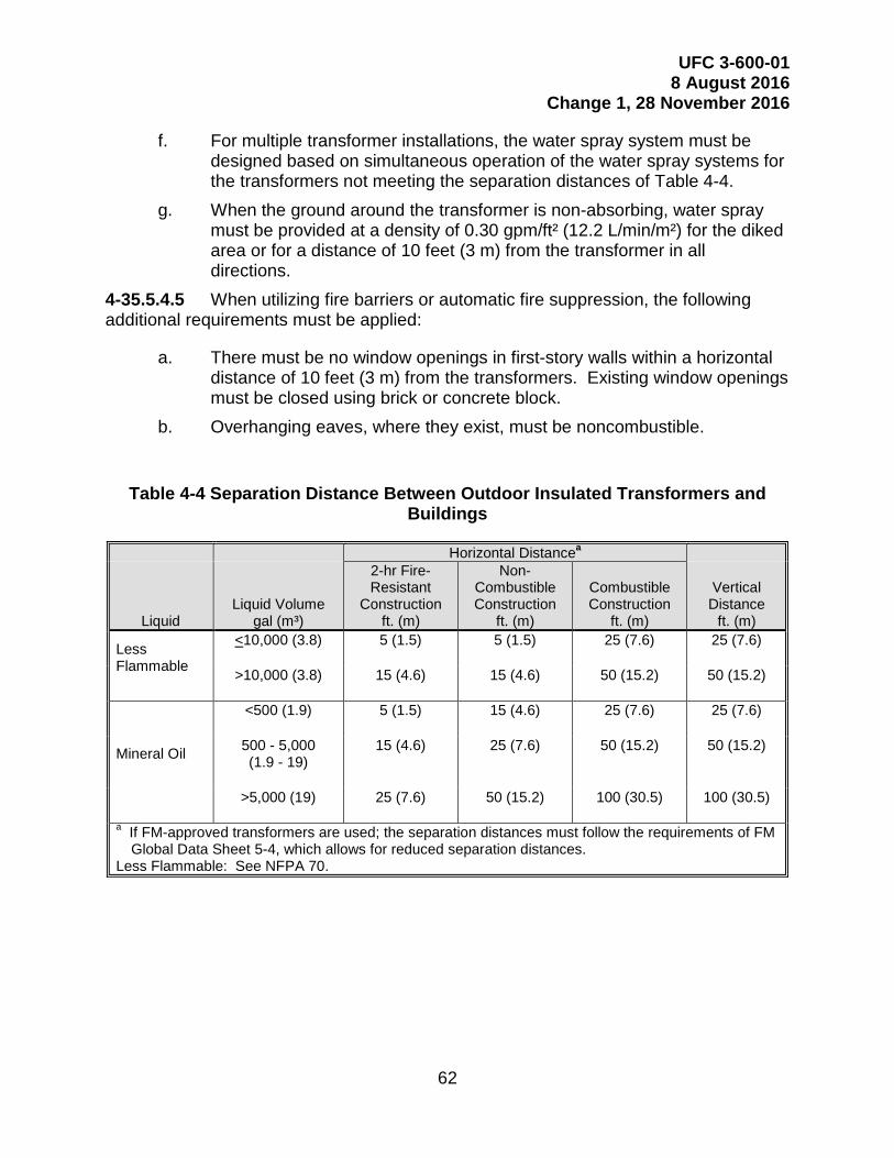
UFC 3-600-01 8 August 2016
Change 1, 28 November 2016
62
f. For multiple transformer installations, the water spray system must be designed based on simultaneous operation of the water spray systems for the transformers not meeting the separation distances of Table 4-4.
g. When the ground around the transformer is non-absorbing, water spray must be provided at a density of 0.30 gpm/ft² (12.2 L/min/m²) for the diked area or for a distance of 10 feet (3 m) from the transformer in all directions.
When utilizing fire barriers or automatic fire suppression, the following 4-35.5.4.5additional requirements must be applied:
a. There must be no window openings in first-story walls within a horizontal distance of 10 feet (3 m) from the transformers. Existing window openings must be closed using brick or concrete block.
b. Overhanging eaves, where they exist, must be noncombustible.
Table 4-4 Separation Distance Between Outdoor Insulated Transformers and Buildings
Horizontal Distancea
Liquid Liquid Volume
gal (m³)
2-hr Fire-Resistant
Construction ft. (m)
Non-Combustible Construction
ft. (m)
Combustible Construction
ft. (m)
Vertical Distance
ft. (m)
Less Flammable
<10,000 (3.8) 5 (1.5) 5 (1.5) 25 (7.6) 25 (7.6)
>10,000 (3.8) 15 (4.6) 15 (4.6) 50 (15.2) 50 (15.2)
Mineral Oil
<500 (1.9) 5 (1.5) 15 (4.6) 25 (7.6) 25 (7.6)
500 - 5,000 (1.9 - 19)
15 (4.6) 25 (7.6) 50 (15.2) 50 (15.2)
>5,000 (19) 25 (7.6) 50 (15.2) 100 (30.5) 100 (30.5)
a If FM-approved transformers are used; the separation distances must follow the requirements of FM Global Data Sheet 5-4, which allows for reduced separation distances.
Less Flammable: See NFPA 70.

UFC 3-600-01 8 August 2016
Change 1, 28 November 2016
63
Table 4-5 Separation Distance Between Outdoor Fluid Insulated Transformers and Equipment (Including Other Transformers)
Liquid Fluid Volume
gal (m³) Distance
ft. (m)
Less Flammable <10,000 (3.8) 5 (1.5) >10,000 (3.8) 25 (7.6)
Mineral Oil <500 (1.9) 5 (1.5)
500 - 5,000 (1.9 - 19) 25 (7.6) >5,000 (19) 50 (15.2)
Less Flammable: See NFPA 70.
4-36 RANGES AND REMOTE LOCATIONS.
Facilities on ranges and other remote locations must comply with NFPA 1141 and NFPA 1144, in addition to (or in lieu of, where appropriate) the requirements of this UFC and the International Wildland Urban Interface Code. The Chapter entitled "Fire Protection" in NFPA 1141 is not applicable.
4-37 RELOCATABLES.
General. 4-37.1
Relocatable facilities must have the same fire protection, construction and 4-37.1.1separation requirements as non-relocatable facilities.
Provide a minimum separation of 50 feet (15.3 m) between groups of high 4-37.1.2hazard occupancies, as defined by NFPA 101 and 15 feet (4.6 m) for all other groups.
Note: For Navy, refer OPNAVINST 11010.33 for regulations and restrictions on the use of relocatable facilities.
Location. 4-37.2
Do not group critical relocatable facilities, such as electronic equipment 4-37.2.1vans, to form areas greater than 6,000 ft2 (557 m2) for non-sprinklered facilities and 12,000 ft2 (1,115 m2) for sprinklered facilities.
Do not group relocatable facilities having high hazard occupancies, as 4-37.2.2defined by NFPA 101, to form areas greater than 4,000 ft2 (372 m2) for non-sprinklered facilities and 8,000 ft2 (743 m2) for sprinklered facilities.
4-38 SENSITIVE COMPARTMENTED INFORMATION FACILITY (SCIF).
General. 4-38.1
Note: SCIF’s should not be confused with radio-frequency shielded enclosures and/or anechoic chambers.

UFC 3-600-01 8 August 2016
Change 1, 28 November 2016
64
See UFC 4-010-05 for additional information. 4-38.1.1
As part of the initial design process for a SCIF, the Certified TEMPEST 4-38.1.2Technical Authority (CTTA) and the security Accrediting Official (AO) must establish both TEMPEST and physical security building element controls prior to designing means and methods of implementing fire protection systems into the SCIF.
Physical Security Door Hardware. 4-38.2
All security door hardware installed on a means of egress door, must 4-38.2.1comply with the provisions of NFPA 101.
Sliding deadbolts are strictly prohibited. 4-38.2.1.1
A spin-dial combination lock, similar to the Lockmaster CDX-10, equipped 4-38.2.1.2with a life safety push-button feature, is acceptable provided the button feature is enabled at all times the SCIF is occupied.
Door personnel “access control systems” shall not restrict free egress at all 4-38.2.1.3times. Badge ID readers may be installed on the interior side of a door for personnel "audit" purposes only, but shall not be connected to any physical security door hardware (i.e. electric door strikes, magnetic locks, etc.) that would restrict single-motion door operation.
Fire Alarm and Mass Notification System (MNS). 4-38.3
See UFC 4-010-05 for requirements pertaining to the installation of fire 4-38.3.1alarm and MNS devices within a SCIF.
Self-amplified fire alarm audio speakers, and associated wiring circuits, can 4-38.3.2be installed within a SCIF with concurrence of the CTTA.
Note: Self-amplified speakers are limited to 0.5 - 24VRMS audio input signal levels. Typically, most fire alarm voice systems are designed for 70.7VRMS audio circuits, and therefore careful economic consideration must be made on how to introduce the fire alarm audio signals into a SCIF.
Fire Sprinkler Systems. 4-38.4
See UFC 4-010-05 for requirements pertaining to the installation of fire 4-38.4.1sprinkler piping penetrations into a SCIF.
Any security mitigation method imposed directly on a sprinkler pipe must 4-38.4.2comply with NFPA 13.
Metallic dielectric unions or grounding clamp(s) and wire(s) are permitted. 4-38.4.3

UFC 3-600-01 8 August 2016
Change 1, 28 November 2016
65
4-39 TENSIONED-MEMBRANE STRUCTURES.
General. 4-39.1
Tensioned-membrane (fabric) structures must meet the requirements of 4-39.1.1NFPA 101 and NFPA 102 as well as all life safety, fire protection, and allowable area requirements for the specific occupancy, in accordance with the other provisions of this UFC.
Tensioned-membrane (fabric) structures must also meet the requirements 4-39.1.2of the applicable use paragraph in this UFC.
Note: The applicable use paragraph may require automatic sprinklers or a fire alarm system which may affect the structural design requirements.
Allowable Area and Separation Distance. 4-39.2
Table 4-6 provides the maximum allowable area and separation 4-39.2.1requirements for all tension fabric structures intended to exceed 12 months of use.
The separation area must be a clear zone adjacent to the tension fabric 4-39.2.2structure.
The clear zone cannot be used for storage and must be clear of vegetation 4-39.2.2.1(maintained lawn is permitted).
The clear zone may be used as a street or driveway, but not for vehicle 4-39.2.2.2parking.
Note: For Navy, see OPNAVINST 11010.33 for regulations and restrictions on the use of relocatable facilities.
Table 4-6 Basic Allowable Area for Tensioned-Membrane/Fabric Structures
SEPARATION
DISTANCE
TYPE of CONSTRUCTION - In Square Feet (Square Meters)
Noncombustible Material Combustible Material
Sprinkler Protection No Sprinkler Protection
Sprinkler Protection No Sprinkler Protection
20 feet (6 m) 36,000 (3,344) 12,000 (1,114) 24,000 (2,229) 8,000 (743)
40 feet (12 m) 72,000 (6,689) 24,000 (2,229) 48,000 (4,459) 16,000 (1,486)
60 feet (18 m) UNLIMITED UNLIMITED UNLIMITED UNLIMITED
UFC 3-600-01 8 August 2016
Change 1, 28 November 2016
66
Tensioned-Membrane (Fabric) Hangars. 4-39.3
Tensioned-membrane (fabric) hangars must comply with the paragraph entitled "Aircraft Facilities".
4-40 TRASH/RECYCLING COLLECTION AND DISPOSAL AREAS.
Central Trash/Recycling Collection and Dumpsters. 4-40.1
Place central trash/recycling collection units and dumpsters 15 feet (4.6 m) or more away from wood frame or metal Facilities or from openings in masonry-walled Facilities.
Collection, Baling, Processing and Storage Rooms. 4-40.2
Rooms for collection, baling and storage must be separated from the remainder of the building by a 1-hour fire barrier and protected with automatic sprinklers.
Where the Facility is not protected with automatic sprinklers, the sprinkler system is permitted to be connected to the domestic water system when permitted by NFPA 13.
Trash/Recycling Chutes. 4-40.3
Provide automatic sprinklers in all trash/recycling chutes installed within a Facility
4-41 VEHICLE PARKING, STORAGE, MAINTENANCE, AND REPAIR FACILITIES.
General. 4-41.1
Facilities used for parking or storage of motor vehicles must comply with 4-41.1.1NFPA 88A.
Facilities used for maintenance and repair of motor vehicles must comply 4-41.1.2with NFPA 30A.
Facilities used for the fueling and dispensing of compressed natural gas 4-41.1.3(CNG) or liquefied natural gas (LNG) for vehicles or vessels must comply with NFPA 52.
Refueler Vehicle Facilities. 4-41.2
Facilities that are covered and enclosed on at least three sides and that are used for the parking, storage, maintenance, and repair of aircraft refueler vehicles must comply NFPA 30A and be provided with the following features:
Automatic sprinkler system or a closed-head foam-water AFFF sprinkler 4-41.2.1system throughout.
For Army, AFFF is not permitted for new systems.

UFC 3-600-01 8 August 2016
Change 1, 28 November 2016
67
Class I Division 1 electrical equipment and wiring throughout the entire pit 4-41.2.2area (below floor level) in accordance with NFPA 70.
Class I Division 2 electrical equipment and wiring throughout the entire 4-41.2.3servicing area and areas not suitably cut-off in accordance with NFPA 70.
Note: This includes the area up to the underside of the roof.
4-42 WAREHOUSE AND STORAGE FACILITIES.
General. 4-42.1
Comply with UFC 4-440-01, except as modified by this UFC. 4-42.1.1
This section applies to Facilities (except ordnance) with a ceiling height 4-42.1.2greater than 12 feet (3.7 m) used for storage, shipping, receiving, packing, and processing of materials.
Storage of hazardous materials, including flammable or combustible liquids, 4-42.1.3must comply with this section and the requirements of the section "Hazardous Materials and Hazardous Waste" in this UFC.
Sprinkler Protection. 4-42.2
Complete automatic sprinkler protection must be provided for warehouses 4-42.2.1and storage Facilities, regardless of floor area or construction type.
Automatic sprinkler systems may be omitted for Facilities with an area less 4-42.2.1.1than 5,000 ft2 (465 m2) with approval of the DFPE.
Note 1: See “Planning” for guidance on determining if sprinkler protection may be omitted for smaller Facilities.
Sprinkler protection must include covered loading docks. 4-42.2.2
Sprinkler protection must follow the design requirements found in NFPA 13. 4-42.2.3The design density, area of application and hose stream requirements of the "Fire and Smoke Protection Features" chapter of this UFC do not apply to high-pile storage as defined by NFPA 13.
Sprinkler protection, at a minimum, must be based on Class IV, non-4-42.2.3.1encapsulated commodities, as defined by NFPA 13, unless a more severe class of storage is anticipated, and must be based on the maximum potential height of storage. The maximum potential height of storage is based on the roof or ceiling height.
If provided, in-rack sprinklers must be supplied from risers that are separate 4-42.2.4from the ceiling sprinklers, except in existing facilities.

UFC 3-600-01 8 August 2016
Change 1, 28 November 2016
68
Racks with solid shelves over 12 feet (3.7 m) in height must be protected 4-42.2.5with in-rack sprinklers at every tier or shelf level.
Sprinkler riser control valves must be readily accessible to the fire 4-42.2.6department from the exterior.
Duration. 4-42.2.7
The water supply must be capable of providing the minimum duration requirements of NFPA 13 for the protection method selected.
Hose Stream Allowance. 4-42.2.8
Provide a hose stream allowance as required by NFPA 13 for the protection method selected.
Roof Slope. 4-42.2.9
Maximum roof slope must be in accordance with NFPA 13.
Bin Storage. 4-42.3
Requirements. 4-42.3.1
Protect in accordance with NFPA 13, except as noted below. 4-42.3.1.1
The ceiling density must be increased by 10 percent or one additional level 4-42.3.1.2of in-rack sprinklers where combustible bins are stored in racks.
Mini-storage and retrieval systems and carousel storage must be protected 4-42.3.1.3in accordance with FM Global Data Sheet 8-33 or FM Global Data Sheet 8-34.
Column Protection. 4-42.4
Steel columns must be protected as required by NFPA 13.
Fire Areas. 4-42.5
Warehouse Fire Areas must not exceed 60,000 ft2 (5,574 m2). Warehouse 4-42.5.1Fire Areas may be increased to 120,000 ft2 (11,148 m2) when all of the following provisions are met:
Ceiling sprinkler design area must be increased by 10 percent. This 4-42.5.1.1requirement does not apply when ESFR sprinklers are utilized.
Dedicated looped service mains must be provided with enough sectional 4-42.5.1.2valves to isolate each Service Lateral around the warehouse.

UFC 3-600-01 8 August 2016
Change 1, 28 November 2016
69
Separation of Fire Areas. 4-42.5.2
Fire Areas shall be separated from other Fire Areas by 4-hour fire walls in 4-42.5.2.1accordance with the IBC Chapter entitled "Fire and Smoke Protection Features".
Other occupancies, such as offices or shops, must be separated from the 4-42.5.2.2warehouse and storage area by a minimum of 1-hour fire-rated construction, unless a higher rating is required by the IBC.
Conveyor and Mechanical Handling System Penetrations. 4-42.6
When mechanical handling systems such as conveyors, penetrate fire 4-42.6.1barriers, the opening must be protected by a fire door or fire shutter.
When a fire door or shutter is not feasible due to the operation of the 4-42.6.2conveyor, the DFPE must be consulted to determine the appropriate protection criteria.
4-43 WATERFRONT FACILITIES.
Waterfront and harbor facilities must comply with all of the following, as applicable:
a. NFPA 303. b. NFPA 307. c. NFPA 312. d. UFC 4-152-01. e. UFC 4-150-02. f. UFC 4-151-10. g. UFC 4-213-10. h. UFC 4-213-12 i. NAVSEA OP-5 (for Navy/Marines only).

UFC 3-600-01 8 August 2016
Change 1, 28 November 2016
70
GENERAL BUILDING HEIGHTS AND AREAS CHAPTER 5
5-1 GENERAL.
Allowances or exceptions that require the Facility to be protected throughout by an approved automatic sprinkler system may only be applied where the system is an approved, electrically supervised automatic sprinkler system as described in NFPA 101. References to IBC Section 903.3.1.1 are replaced with NFPA 13. References to IBC Section 903.3.1.2 are replaced with NFPA 13R.
5-2 BUILDING HEIGHT LIMITATIONS.
Conform to the requirements of IBC Chapter 5.
5-3 BUILDING AREA LIMITATIONS.
Conform to the requirements of IBC Chapter 5.
Note: IBC Chapter 5 does not permit area increases for sprinkler systems if the sprinkler system is designed per NFPA 13R.
5-4 OCCUPANCY SEPARATION.
General. 5-4.1
Occupancy separation must comply with the IBC Chapter 5. Do not use 5-4.1.1NFPA 101 for occupancy separation requirements, except as noted below.
NFPA 101 must be utilized for occupancy separations of medical funded 5-4.1.2projects, healthcare, ambulatory healthcare and all facilities required to comply with The Joint Commission standards.
5-5 INCIDENTAL USE.
NFPA 101 must be utilized for protection from hazards. IBC requirements for separation of incidental uses are not permitted.

UFC 3-600-01 8 August 2016
Change 1, 28 November 2016
71
This Page Intentionally Left Blank

UFC 3-600-01 8 August 2016
Change 1, 28 November 2016
72
TYPES OF CONSTRUCTION CHAPTER 6
6-1 GENERAL.
Conform to the requirements of IBC Chapter 6, except as modified by this UFC.
6-2 SEPARATION BETWEEN BUILDINGS.
Conform to the requirements of the IBC, except as modified by this UFC.

UFC 3-600-01 8 August 2016
Change 1, 28 November 2016
73
This Page Intentionally Left Blank

UFC 3-600-01 8 August 2016
Change 1, 28 November 2016
74
FIRE AND SMOKE PROTECTION FEATURES CHAPTER 7
7-1 GENERAL.
Conform to the requirements of NFPA 101 except as noted below.
Where IBC Chapter 5 or 6 specifically references IBC Chapter 7, utilize the specific IBC Chapter 7 reference.
Note: For example, IBC Section 508.4.4.1 specifically references IBC Sections 707 and 711. When utilizing IBC Section 508.4.4.1, utilize IBC Sections 707 and 711, otherwise IBC Sections 707 and 711 are not to be used unless specifically referenced.
7-2 MARKING AND IDENTIFICATION.
Conform to the requirements of the IBC for marking and identification of fire walls, fire barriers, fire partitions, smoke barriers, smoke partitions or any other wall required to have protected openings.
For Navy, Marines, and NRO, stenciling must be provided and spaced no more than 10 foot, measured edge to edge horizontally along the wall or partition.
7-3 NON-LOAD BEARING PARTITIONS AND BARRIERS.
Comply with NFPA 101 for fire resistance ratings of non-load bearing partitions and barriers, except occupancy separation as indicated in Chapter 5.
7-4 PROTECTION OF STRUCTURAL MEMBERS.
General. 7-4.1
Comply with IBC Chapter 7 for protection of structural members, except as noted below.
Sprayed Fire-Resistant Materials. 7-4.2
Sprayed fire-resistant materials must be medium or high density 7-4.2.1cementitious or an intumescent thin-film coating.
Note: Intumescent thin-film coating is not the same material as intumescent paint.
Mineral fiber or low-density cementitious materials are not permitted. 7-4.2.2
Provide UL-listed floor/ceiling and UL-listed roof/ceiling assemblies that do 7-4.2.3not require the underside of the roof or floor deck to have spray-applied fireproofing. The assembly must be designed so only columns, beams, and trusses receive spray-applied fireproofing to achieve the rating for the assembly.
UFC 3-600-01 8 August 2016
Change 1, 28 November 2016
75
Ceilings. 7-4.3
Listed floor/ceiling or roof/ceiling assemblies that utilize suspended gypsum wallboard or acoustical tile ceilings must not be used to achieve required fire resistance rating of building structural elements.
7-5 SMOKE AND HEAT VENTS.
General. 7-5.1
Smoke and heat vents must not be provided unless specifically required by 7-5.1.1this UFC.
Note: Smoke and heat vents should be considered in Facilities where a high rate of heat release is anticipated during a fire such as indoor firing ranges with rubber impact zones.
Where provided in Facilities without automatic sprinklers, smoke and heat 7-5.1.2vents must be arranged to operate automatically in accordance with NFPA 204.
Where provided in Facilities with automatic sprinkler protection, smoke and 7-5.1.3heat vents must be arranged to operate in the manual mode only.
Note: Skylights can be used as a method of providing manual smoke and heat vents.
7-6 HIGH VOLUME LOW SPEED (HVLS) FANS.
Comply with NFPA 13, except all HVLS fans shall be interlocked to shut down immediately upon any fire alarm activation.
7-7 PLASTIC PIPE AND CONDUIT.
Penetrations. 7-7.1
Penetrations by plastic pipe or conduit through fire-rated walls, partitions, shafts, and floors must be fire stopped by an approved or listed method in accordance with ASTM E814 or UL 1479.
Prohibited Locations. 7-7.2
Plastic pipe and conduit must not be installed in exit stair enclosures, or in air plenum spaces, unless specifically listed for that application.

UFC 3-600-01 8 August 2016
Change 1, 28 November 2016
76
INTERIOR FINISHES CHAPTER 8
8-1 GENERAL.
Conform to the requirements of NFPA 101.
8-2 DROP-OUT PANELS.
Drop-out panels, as defined in NFPA 13, must not be used.
8-3 INSULATION.
Requirements. 8-3.1
Use thermal and acoustical insulation with a flame spread (FS) rating not 8-3.1.1higher than 75, and a smoke developed (SD) rating not higher than 150 when tested in accordance with ASTM E84 (NFPA 255).
Exposed insulation in concealed spaces of sprinkled buildings must be 8-3.1.2specified to have a flame spread of 25 or less and a smoke developed rating of 50 or less (including paper covering).
Note 1: This is to prevent the space from being defined as a combustible concealed space, which would require sprinkler protection in accordance with NFPA 13.
Note 2: Acceptable types of insulation blankets per Federal Spec HH-521F are Type I, Type II (Class A only), and Type III (Class A only).
Exceptions to Insulation Criteria. 8-3.2
For certain types of insulation installation, the exceptions described in paragraphs entitled "Flame Spread – No Smoke Developed Rating Limitation" and "No Flame Spread or Smoke Limitation" below will apply.
Flame Spread - No Smoke Developed Rating Limitation. 8-3.2.1
Compliance with the SD rating limitation is not required, and a FS rating up to 100 is permitted for insulation, including insulating sheathing installed within wall assemblies. In such installations, conform to the requirements for interior finish with a minimum fire resistance rating of 15 minutes when tested in accordance with ASTM E119.
No Flame Spread or Smoke Limitation. 8-3.2.2
Compliance with FS and SD limitations are not required for the following applications:
a. Insulation installed above poured concrete or poured gypsum roof decks, nominal 2-in. (50.8 mm) thick tongue-and-groove wood plank roof decks, or precast roof deck panels or planks that are approved by a Nationally
UFC 3-600-01 8 August 2016
Change 1, 28 November 2016
77
Recognized Testing Laboratory (NRTL), as noncombustible roof deck construction.
b. Insulation installed above roof decks where the entire roof construction assembly, including the insulation, is UL-listed as Fire Classified, or FM-approved for Class I roof deck construction or equal listing or classification by a NRTL.
c. Insulation contained entirely within panels where the entire panel assembly used in the construction application meets the cited FS and SD limitations.
d. Insulation isolated from the interior of the building by masonry walls, masonry cavity walls, insulation encased in masonry cores, or concrete floors.
e. Insulation installed over concrete floor slabs and completely covered by wood tongue-and-groove flooring without creating air spaces within the flooring system.
f. Insulation completely enclosed in hollow metal doors. g. Insulation installed between new exterior siding materials and existing
exterior siding or wood board, plywood, fiberboard, or gypsum exterior wall sheathing.
Note: The exception to SD limitations described in this paragraph is not applicable to correctional facilities.

UFC 3-600-01 8 August 2016
Change 1, 28 November 2016
78
FIRE PROTECTION SYSTEMS CHAPTER 9
9-1 FIRE DEPARTMENT (EMERGENCY) VEHICLE ACCESS.
All-Weather Ground Access. 9-1.1
All Facilities greater than 5,000 ft2 (465 m2), or more than two stories in height, must have at least one means of all-weather ground access to allow emergency vehicles unimpeded access to the Facility. All-weather ground access must be paved, start from the road, and terminate no farther than 33 feet (10 m) from an exterior door accessible for fire department ingress (i.e. a stair door or some other exterior door that provides access to the Facility interior). The route between the access surface and exterior door must be able to be traversed without the use of a ladder.
An engineered all-weather surface that is not paved may be provided if approved by the DFPE.
Aerial Apparatus Access. 9-1.2
New facilities four stories or more in height and all new warehouses must be provided with suitable all-weather ground access for aerial apparatus on a minimum of two sides of the perimeter of the structure. The access must be parallel to at least one entire side of the Facility with windows to allow aerial access to the entire side. The distance between the aerial apparatus access and the Facility must be based on the responding aerial apparatus and Facility height and be approved by the DFPE.
Note: The intent of this paragraph is to provide aerial apparatus access to two sides of the building, with one side having access along the entire side of the building so that the aerial apparatus has multiple locations to set up operations. Aerial apparatus access must be coordinated with fire department ingress noted above.
Vehicle Access. 9-1.3
All force protection equipment, such as bollards or gates, must not require more than one person to remove or open. Access may require fire apparatus to drive over a curb. Any locking device controlling vehicle access must be under control of the fire department or 24-hour security personnel located at the specific Facility. Dimensions of fire lanes and turnarounds must comply with NFPA 1. Vehicle access must be coordinated with the Installation or responding fire department.
Fire Department Connection. 9-1.4
Facilities with fire department connections for fire suppression systems must be provided with suitable all-weather ground access surface for any apparatus within 150 feet (45 m) of such fire department connections.

UFC 3-600-01 8 August 2016
Change 1, 28 November 2016
79
9-2 FIRE FLOW FOR FACILITIES.
Sprinklered Facilities. 9-2.1
Fire Flow for sprinklered Facilities must be a minimum of 1,000 gpm at 20 psi (3,785 L/min at 138 kPa). Where the Fire Flow cannot be met, the DFPE is permitted to approve a reduction in Fire Flow. Fire Flow is calculated independently of the Fire Water Demand.
Non-sprinklered Facilities. 9-2.2
Fire Flow shall be in accordance with NFPA 1, except the following special Facilities.
Ship Berthing and Drydock Facilities. 9-2.2.1
Refer to the paragraph entitled "Waterfront Facilities" for Fire Flow requirements for ship berthing and drydock facilities.
Family Housing. 9-2.2.2
The Fire Flow for non-sprinklered family housing must be as follows:
a. One-story - 500 gpm (1,900 L/min) for 90 minutes. b. Two-story - 750 gpm (2,840 L/min) for 90 minutes. c. Three-story and above - 1,000 gpm (3,785 L/min) for 90 minutes.
Aircraft Parking and Refueling Facilities. 9-2.2.3
A minimum Fire Flow of 1,000 gpm (3,785 L/min) for a 2-hour duration is to be provided for all such Facilities.
Yard and Outdoor Storage. 9-2.2.4
Yard and outdoor storage must comply with the requirements of NFPA 80A, 9-2.2.4.1and FM Global Data Sheet 1-20.
Aisle widths and separation distances must be maintained to limit the 9-2.2.4.2exposure to nearby Facilities and to facilitate manual firefighting operations.
Vehicle Parking Areas. 9-2.2.5
A minimum Fire Flow of 500 gpm (1900 L/m) for a 2-hour duration must be provided for all such areas.
UFC 3-600-01 8 August 2016
Change 1, 28 November 2016
80
9-3 SERVICE MAINS AND LATERALS.
General. 9-3.1
Service Mains and Service Laterals must comply with AWWA M31, NFPA 9-3.1.124 and UFC 3-230-01, except where specifically modified by this UFC.
Note: The velocity limits in UFC 3-230-01 apply to transmission mains, not service mains or laterals.
This section applies to both dedicated (fire only) and combined (domestic 9-3.1.2and fire) water distribution systems.
For Service Mains served by fire pumps or Service Laterals serving fire 9-3.1.3pumps, velocities must be calculated using 150 percent of the rated capacity of the fire pump.
Provide appropriate corrosion protection based on pipe material and 9-3.1.4corrosive properties of the water supply and earth.
Where cathodic protection is indicated based upon present conditions, 9-3.1.5comply with the following: For the Army, comply with UFC 3-570-02A, for the Navy and Marines, comply with UFC 3-570-02N, and for Air Force, comply with AFI 32-10454 and UFC 3-570-06.
Service Mains. 9-3.2
Service Mains must be sized to accommodate Fire Flow plus domestic and 9-3.2.1industrial demands that cannot be restricted during fires.
Service Mains must be looped to provide at least 50 percent of the required 9-3.2.2Fire Flow in case of a single break.
Service Mains must not be dead-end. 9-3.2.3
Service Mains must be sized so that the minimum residual pressure 9-3.2.4available, at 150 percent of a Facility fire pump rating, if provided, is not less than 20 psi.
Service Laterals. 9-3.3
Not more than two fire hydrants can be located on a Service Lateral. 9-3.3.1
Minimum size Service Lateral for fire sprinkler systems must be not less 9-3.3.2than 6-in. (150 mm) in diameter.
For NFPA 13R systems, the Service Lateral is permitted to be 4-in. (100 9-3.3.2.1mm) if supported by hydraulic calculations.

UFC 3-600-01 8 August 2016
Change 1, 28 November 2016
81
For NFPA 13D systems, the minimum Service Lateral size shall be based 9-3.3.2.2on hydraulic calculations.
The minimum residual pressure in a Service Lateral must not be less than 9-3.3.320 psi at the greater of Fire Flow or Fire Water Demand. This residual pressure must be maintained at the inlet of the backflow preventer or suction side of the fire pump, whichever is closer to the Service Main.
A Service Lateral supplying a fire pump must be able to support 150 9-3.3.4percent of the fire pump rated capacity without falling below the required net positive suction head (NPSH) at the suction side of the pump. Where NPSH cannot be met at 150 percent of the fire pump rated capacity, the DFPE is permitted to reduce the required flow at NPSH, but in no case is it permitted to be less than the required fire suppression system demand.
Note: Piping downstream of the fire pump is not a Service Lateral. Piping downstream of the fire pump shall be sized based on the Fire Water Demand of the Facility or the minimum required by NFPA 20, whichever is greater, not 150 percent of the fire pump rated capacity.
Valves. 9-3.4
Control valves must be provided in each source of water supply, such as 9-3.4.1tanks and pumps.
A control valve must be provided on the Service Lateral downstream of the 9-3.4.2connection to the Service Main.
A sufficient number of sectional valves must be provided on the Service 9-3.4.3Main, so that not more than a combined total of five hydrants or the Service Laterals to not more than three separate buildings are out of service due to a single break.
Sectional valves on Service Mains may be key-operated type. New valves 9-3.4.4must open by counter-clockwise rotation of the stem.
Supervision. 9-3.4.5
When provided, PIV’s must be supervised using a lock or tamper seal, at a minimum.
Hydrants. 9-3.5
Fire hydrants must be UL-listed, FM-approved, or listed or classified by an 9-3.5.1NRTL and must have two 2 1/2-in. (65 mm) hose outlets and one 4 1/2-in. (115m) outlet with national standard fire hose threads in accordance with NFPA 1963.
Comply with the Installation fire department or local responding fire department when they require a different arrangement or hose threads.
UFC 3-600-01 8 August 2016
Change 1, 28 November 2016
82
Wet barrel or California-type hydrants are preferable in areas where there is 9-3.5.2no danger of freezing. Dry barrel or traffic-type hydrants must be used in areas where there is a danger of freezing. Hydrants must be aboveground type and match the type used on the Installation.
In DoD Installations serviced by only local fire departments, hydrant hose 9-3.5.3threads must meet local requirements.
See AWWA Manual M 17 and AWWA Manual M 31 for additional 9-3.5.4information.
Note: Overseas Installations with current below grade hydrants in accordance with local national policy are acceptable.
\1\/1/Hydrant caps/barrels must be color coded to prevent cross-connection. 9-3.5.5In the absence of an Installation established color code standard, the following colors must be used; red for non-potable water, yellow for potable water, and purple for reclaimed/reuse water. All hydrants must also be marked based on the Fire Flow capacity, in accordance with NFPA 291 or by the Installation established marking standard
Clearly mark each new hydrant with an identification number assigned by 9-3.5.6the Installation.
Construction Requirements. 9-3.5.7
a. Installation must be in accordance with NFPA 24 except as modified by this UFC.
b. Hydrants must be installed adjacent to paved areas, accessible to fire department apparatus.
c. Service Lateral supplying hydrants must be minimum 6-in. (150 mm) and valved at the connection to the Service Main.
d. Barrels must be long enough to permit at least 18-in. (450 mm) clearance between the center of the 4 1/2-in. (115 mm) outlet and grade.
e. The ground must be graded so that any surface drainage is away from the hydrant.
f. The 4 1/2-in. (115 mm) outlet must be perpendicular to the street to allow straight connection to the pumper.
g. Landscaping, fencing, bollards and similar must be located a minimum of 24-in. (610 mm) from the horizontal centerline of the hydrant and not directly in front of any outlet.
h. For hydrants adjacent to airfield pavement, comply with UFC 3-260-01.
UFC 3-600-01 8 August 2016
Change 1, 28 November 2016
83
Spacing Requirements. 9-3.5.8
A sufficient number of hydrants must be provided so that Fire Flow can be 9-3.5.8.1met without taking more than 1,250 gpm (4,740 L/min) from any single hydrant.
All parts of the Facility exterior must be within 350 feet (106 m) of a hydrant 9-3.5.8.2with consideration given to accessibility and obstructions.
Hydrants must be located with consideration given to emergency vehicle 9-3.5.8.3access.
Hydrants must also be spaced in accordance with the following 9-3.5.8.4requirements:
a. At least one hydrant must be located within 150 feet (45 m) of the fire department connection.
b. Hydrants protecting warehouses must be spaced at 300 feet (91 m) maximum intervals.
c. Exterior storage and military/tactical equipment/vehicle parking must be provided with hydrants spaced at 300 feet (91 m) maximum intervals around the perimeter.
Note: Military/tactical equipment/vehicle parking applies to large parking areas typically found at reserve facilities or similar locations. This does not apply to small parking areas.
d. Hydrant spacing must be spaced at 600 feet (182 m) maximum intervals for non-sprinklered family housing.
e. Hydrant spacing must not exceed 1,000 feet (305 m) in areas where all family housing is provided with sprinkler protection.
Protection. 9-3.5.9
Hydrants located adjacent to parking areas, vehicle traffic areas or other areas subject to mechanical damage, must be protected by bollards. The bollards must be located so they are not directly in front of an outlet. The bollards must allow clearance to attach hoses, allow for the removal of the hydrant caps, and for the hydrant to be opened and closed without obstructions. Refer to UFC 3-260-01 where bollards are required for hydrants located adjacent to aircraft parking and servicing aprons.
Pressure-Regulating Valves (PRVs). 9-3.6
PRVs must not be provided on Distribution Mains, Service Mains or Service Laterals.
UFC 3-600-01 8 August 2016
Change 1, 28 November 2016
84
9-4 FACILITY ON-SITE WATER STORAGE.
General. 9-4.1
On-site fire protection water storage must comply with NFPA 22, except 9-4.1.1where specifically modified by this UFC.
For Army projects where on-site storage is provided via tanks, the storage 9-4.1.2must be divided into two or more approximately equal capacity tanks, arranged so that at least one-half of the water supply will always be available during tank maintenance.
The discharge or suction line(s) from each individual tank or reservoir 9-4.1.3section must be sized to deliver the maximum required flow.
Quantity. 9-4.2
The total supply stored for fire protection purposes must be sufficient to 9-4.2.1meet the Facility’s maximum required Fire Water Demand for the applicable duration specified in this UFC. Provide a usable storage capacity equal to 120 percent of the maximum fire protection system demand.
In calculating the fire protection water storage requirement, a reduction in 9-4.2.2storage capacity is acceptable if an adequate replenishment source is available. Factors that must be evaluated include the reliability of the makeup supply, its sustained flow capacity, its method of operation (automatic or manual), and flow limitations imposed by the capacity of treatment operations.
Replenishment of Storage. 9-4.3
The water storage must be capable of being self-replenished to its required volume within 48 hours, during normal domestic and industrial consumption of the supplying utility.
Monitoring. 9-4.4
The water level must be remotely monitored in accordance with NFPA 22 9-4.4.1and NFPA 72 by the Installation Fire Alarm Reporting System.
In locales subject to freezing, water temperature of aboveground storage 9-4.4.2tanks must likewise be monitored by the Installation Fire Alarm Reporting System.
9-5 FIRE PUMPS.
General. 9-5.1
Fire pumps must comply with NFPA 20, except where specifically modified 9-5.1.1by this UFC.

UFC 3-600-01 8 August 2016
Change 1, 28 November 2016
85
Fire pumps must be located in a detached, noncombustible pump house or 9-5.1.2located in a fire-rated room in accordance with NFPA 20 with direct access from the exterior.
Maintenance access must be provided to the pump and driver so that either 9-5.1.3can be removed from the fire pump room. Access is permitted to be via double doors or overhead door directly to the exterior. This is in addition to the normal means of egress required by NFPA 101.
Provide a minimum of 3 feet (915 mm) of clearance on one side of the fire 9-5.1.4pump assembly for maintenance and in front of the pump controller or the minimum required by NFPA 70. A clear width of 3 feet must be provided from the room entry to the fire pump assembly and controller.
Provide a minimum of 3 feet (915 mm) access to and in front of all 9-5.1.5equipment and 6-in. (150 mm) behind the equipment, (e.g., control valves, check valves, etc.).
Provide labeling on the surfaces of the piping in the pump room to show the 9-5.1.6water flow direction and pipe function (e.g., "Suction", "Discharge", "To Fire Dept. Connection", "To Bypass", "To Test Header", "To Standpipe", "To Sprinkler System"). Provide white painted stenciled letters and arrows, a minimum of 2-in. (50 mm) in height and visible from at least three sides when viewed from the floor.
The maximum Fire Water Demand shall not exceed 140 percent of rated 9-5.1.7pump capacity. The pressure at the inlet of the pump at 150 percent of the rated pump capacity shall not be less than the required net positive suction head in accordance with NFPA 20. Where NPSH cannot be met at 150 percent of the fire pump rated capacity, the DFPE is permitted to reduce the required flow at NPSH, but in no case is it permitted to be less than the required fire suppression system demand.
Terminate all drainage piping and test piping from the fire pump or 9-5.1.8associated appurtenances (e.g., circulation relief valve, bowl drains, etc.), including backflow preventers, to a floor drain or to the exterior of the Facility so it will not cause damage.
Provide concrete pads or splash blocks where discharge location is to other 9-5.1.8.1than a concrete slab. Splash blocks shall be large enough to mitigate erosion and shall not become dislodged during a full flow of the drain. Ensure all discharged water drains away from the Facility and does not cause property damage
Discharge to the exterior must not interfere with exiting from the Facility. 9-5.1.8.2Water discharge must not cross an exit or exit discharge.
Drainage piping of less than 3/4-in. (20 mm) may discharge to a floor drain. 9-5.1.8.3

UFC 3-600-01 8 August 2016
Change 1, 28 November 2016
86
Full flow relief valve piping must discharge safely in accordance with NFPA 9-5.1.920. If an on-site water storage tank or reservoir is provided, the piping must discharge back to the tank or reservoir.
Pump Type. 9-5.2
A fire pump may be either a horizontal or vertical centrifugal pump, or a vertical turbine pump; whichever is most economical and appropriate for the intended use.
Pump Start and Shutdown. 9-5.3
Fire pumps must be arranged to start automatically. 9-5.3.1
Fire pumps must be arranged to automatically shut down after reaching the 9-5.3.2stop pressure and the expiration of a minimum 10-minute run timer. Stop pressure must be at least 5 psi below maximum churn pressure at the lowest available static pressure.
Note: The lowest available static pressure should be utilized in determining churn pressure so that the stop pressure can be achieved with low pressure. The 5 psi differential is used to allow for gauge error.
When fire pumps are supplied directly by a water tank, the fire pumps must 9-5.3.3be arranged to shutdown manually.
Fire pump activation (run) shall transmit an alarm condition to the 9-5.3.4Installation receiving station, or remote receiving station, but not activate the Facility notification appliance circuits (i.e. no audible/visual notification in the protected Facility(s)).
Pump Drive. 9-5.4
Electric power must comply with NFPA 20. Where electric power is 9-5.4.1available from a Reliable Power Source of adequate capacity, electric motor driven fire pumps must be used.
When a Reliable Power Source is not available, electric motor driven fire 9-5.4.2pumps must be provided with a secondary power source (i.e. emergency generator with automatic transfer switch). See Chapter 2 for the definition of Reliable Power Source.
A diesel engine driven fire pump is permitted in lieu of an electric motor 9-5.4.3driven fire pump when a Reliable Power Source is not available.
Note: Air Force preference is to utilize electric motor driven fire pump(s) with a secondary power source when a Reliable Power Source is not available.
Diesel engine driven fire pumps must not be arranged to start automatically 9-5.4.4upon loss of normal power.

UFC 3-600-01 8 August 2016
Change 1, 28 November 2016
87
Controllers. 9-5.5
Soft start, reduced voltage controllers are required for electric motor driven 9-5.5.1fire pumps equal to or greater than 100 hp or when the fire pump is connected to an emergency generator.
Any starting method permitted by NFPA 20 is acceptable for electric motor 9-5.5.2driven fire pumps less than 100 hp, regardless of power source and must comply with UFC 3-520-01.
Limited service controllers are permitted when approved by a NRTL and 9-5.5.3NFPA 20.
Variable speed controllers are permitted when approved by a NRTL. 9-5.5.4
Pump Bypass. 9-5.6
Provide a bypass in accordance with NFPA 20 around all fire pumps that take suction from a Service Lateral.
Electric Circuits for Diesel Engine Driven Pumps. 9-5.7
Provide separate hard-wired electric circuits for the pump controller, engine starting system battery charger and hard-wired electric circuit for the engine block heater.
Test Connections. 9-5.8
Provide a test header manifold on the Facility exterior that permits flow 9-5.8.1testing directly from the header. Coordinate the location of test header with other disciplines to ensure flow from test header does not discharge onto other equipment or cause property damage.
Provide a flow meter installed in accordance with NFPA 20. 9-5.8.2
The flow meter shall be installed in series with the test header unless it is 9-5.8.2.1piped to discharge into a water storage tank or reservoir.
Where a water storage tank or reservoir provides suction to the fire pump, 9-5.8.2.2the flow meter discharge must be piped back to a water storage tank or reservoir.
9-6 FIRE SUPPRESSION SYSTEMS.
General. 9-6.1
This section applies to all fire suppression/extinguishing systems including, 9-6.1.1but not limited to: automatic sprinkler systems; water spray systems; foam systems; standpipe systems; dry chemical extinguishing systems; wet chemical extinguishing

UFC 3-600-01 8 August 2016
Change 1, 28 November 2016
88
systems; clean agent fire extinguishing systems; water mist fire protection systems; carbon dioxide systems; and, halon 1301 systems.
Fire suppression systems must be designed and installed in accordance 9-6.1.2with the applicable NFPA standard, except where specifically modified by this UFC.
Connections to Fire Alarm Reporting Systems. 9-6.2
Where fire suppression systems are installed in or at Facilities on 9-6.2.1Installations with Fire Alarm Reporting Systems, the fire suppression systems must be connected to the Fire Alarm Reporting System for transmission of alarms, supervisory and trouble signals.
Where installed in areas without an Installation Fire Alarm Reporting 9-6.2.2System, the fire suppression system must be connected to a remote supervising station for alarm, supervisory and trouble signals.
Plans and Calculations. 9-6.3
All working (shop) drawings, regardless of the type of fire suppression 9-6.3.1system, must meet the drawing requirements in NFPA 13 for Working Drawings, unless the system specific standard has requirements for working drawings.
For new or modified systems, working (shop) drawings and calculations 9-6.3.2must be prepared by an individual that has obtained National Institute for Certification in Engineering Technologies, Automatic Sprinkler Systems, Level III certification or Special Hazards Suppression Systems, Level IV certification, as applicable to the project. The QFPE must review the shop drawings, hydraulic calculations and material submittals. The shop drawings must bear the Review Stamp of the QFPE prior to submitting the fire extinguishing system shop drawings to the DFPE.
For Army projects, construction (shop) drawings and calculations must be prepared by, or prepared under the immediate supervision, of the QFPE. The QFPE must affix their professional engineering stamp with signature to the shop drawings, calculations and material data sheets, indicating approval prior to submitting the fire extinguishing system shop drawings to the DFPE. The QFPE must monitor the installation of the fire protection systems and certify in writing that the fire protection systems have been constructed and operate as intended in the design plans and specifications.
When twenty or less sprinklers are modified or relocated, shop drawings, 9-6.3.3hydraulic calculations and material submittals are not required to be submitted.
The preparer of the shop drawings must perform calculations (i.e. hydraulic 9-6.3.4calculations, agent flow calculations) in accordance with the applicable NFPA standard, demonstrating that the design will provide an adequate supply for the fire suppression systems. Calculations must be submitted no later than the first shop drawing submission.

UFC 3-600-01 8 August 2016
Change 1, 28 November 2016
89
Hydraulic calculations must include a minimum pressure drop across 9-6.3.5backflow preventers of 12 psi (82.7 kPa).
When nitrogen is utilized in dry or preaction sprinkler systems, a C-factor of 9-6.3.6120 is permitted to be used in hydraulic calculations.
The dimension from the edge of standpipes and fire suppression system 9-6.3.7risers to the nearest adjacent wall(s) must be indicated on the drawings when located in stairs or other portions of the means of egress.
The QFPE must consult with the DFPE or Installation fire safety agency to 9-6.3.8clarify location of fire department connection(s) or type of hose threads.
Note: The Installation fire safety agency will typically be the fire department.
Waterflow Testing. 9-6.4
Conduct waterflow tests, in accordance with the procedures contained in NFPA 291 to determine available water supply for the water-based fire extinguishing systems. The flow test must be performed under the direction of the QFPE.
Note: Hydraulic calculations should be based on a waterflow test that was performed no more than 6 months prior to submission of the calculations.
Fire Water Demand. 9-6.5
Domestic demand and hose stream are not required to be included in the Fire Water Demand when supplied from a utility or source separate from that supplied to the fire suppression system (i.e. tank for fire, water main for hydrant or domestic). Domestic or industrial demands are not included in the Fire Water Demand where means are provided to restrict these demands during a fire incident.
Backflow Prevention and Cross Connection Control. 9-6.6
The installation of backflow prevention and cross connection control must comply with AWWA Manual M 14.
Potable Water Supply. 9-6.6.1
For new fire suppression systems using water only, follow the Installation requirements for proper type of backflow prevention.
Installation. 9-6.6.2
Install a reduced pressure type backflow prevention device where 9-6.6.2.1antifreeze, foam or other chemicals are added into the system.

UFC 3-600-01 8 August 2016
Change 1, 28 November 2016
90
For locations subject to freezing, backflow preventers must be located in 9-6.6.2.2the Facility or within a heated enclosure. Provide a low temperature supervisory alarm connected to the Facility FACP for heated enclosures. Heat trace must not be used unless a heated enclosure cannot be provided.
Install horizontal backflow preventers so that the bottom of the assembly is 9-6.6.2.3no greater than 24-in. (610 mm) above the finished floor/grade. Install vertical backflow preventers so that the upper operating handwheel is no more than 6 feet (1.8 m) above the finished floor/grade.
Prior to the installation of backflow preventers in an existing fire 9-6.6.3suppression system, a thorough hydraulic analysis, including hydraulic calculations and flow test, must be performed to ensure that the water supply is still adequate for the system with the backflow preventer. If the backflow preventer causes the demand to exceed the water supply, the backflow preventer must not be installed until the water supply is corrected to support the new demand.
When installed as part of a fire pump system, piping and fittings suitable for 9-6.6.4potable water shall be used upstream of the backflow preventer in accordance with local environmental requirements. The backflow preventer must be located where required by NFPA 20 unless the local environmental requirements differ.
Test Header. 9-6.6.5
All new water-based fire suppression systems must have test valves 9-6.6.5.1installed downstream of the backflow preventer. These valves must be angle or globe valves with 2.5-inch male National Standard Hose Threads with cap and chain. Provide one valve for each 250 gpm, and fraction thereof, of system design flow (e.g., a volumetric waterflow rate of 450 gpm would require two valves).
Meters. 9-6.7
Where meters are installed on a Service Lateral serving fire suppression systems, hydrants, or standpipe systems, they must be listed by a NRTL as fire service meters.
Painting and Labeling. 9-6.8
Labeling must be in accordance with MIL-STD-101, except as modified by 9-6.8.1this section.
Provide labeling on the surfaces of all feed and cross mains to show the 9-6.8.2pipe function (e.g., "Sprinkler System", "Fire Department Connection", "Standpipe"). Provide white painted stenciled letters and arrows, a minimum of 2-in. (50 mm) in height and visible from at least two sides when viewed from the floor.
All fire suppression system valves must be marked with permanent tags 9-6.8.3indicating normally open or normally closed.

UFC 3-600-01 8 August 2016
Change 1, 28 November 2016
91
9-7 AUTOMATIC SPRINKLER SYSTEMS.
General. 9-7.1
Automatic sprinkler systems must comply with NFPA 13, except where 9-7.1.1specifically modified by this UFC.
When automatic sprinkler protection is required by this UFC, it is meant that 9-7.1.2a wet pipe sprinkler system is to be provided, unless environmental concerns indicate otherwise (e.g., freezing conditions).
Sprinkler systems must use equipment and devices listed by a NRTL. 9-7.1.3
Application Requirements. 9-7.2
Complete automatic sprinkler protection must be provided for the following 9-7.2.1Facilities:
Single-story, Type I or II construction Facilities greater than 15,000 ft2 9-7.2.1.1(1,394 m2) gross floor area
Multi-story Facilities, regardless of floor area or construction type. 9-7.2.1.2
Single-story, Type III, IV and V construction greater than 5,000 ft2 (465 m2) 9-7.2.1.3
As specified by other sections of this UFC. 9-7.2.1.4
As required by the IBC for area, height or construction type modifications. 9-7.2.1.5
The requirement for automatic sprinkler protection for tension fabric 9-7.2.2structures must be determined by the DFPE
New or modified automatic sprinkler protection for existing Facilities must 9-7.2.3comply with the requirements of the "Existing Facilities" chapter of this UFC.
Sprinkler protection must be provided for additions or partial Renovations of 9-7.2.4existing Facilities if the entire gross floor area of the Facility (including the addition, if provided) exceeds the area limitations noted above.
The addition or portion of the Facility being renovated must include sprinkler 9-7.2.4.1protection and be designed to support sprinklers for the remainder of the Facility when it is renovated.
Design Requirements. 9-7.3
Facilities requiring sprinkler protection must be provided with sprinkler 9-7.3.1systems that are designed using the Area/Density Method of NFPA 13, except the

UFC 3-600-01 8 August 2016
Change 1, 28 November 2016
92
discharge requirements for non-storage occupancies must be in accordance with Table 9-3, unless otherwise specified in this UFC.
Note: Common DoD hazard classifications that are not noted in NFPA 13 can be found in Appendix B.
Residential occupancies must comply with the residential design criteria in 9-7.3.1.1NFPA 13, NFPA 13R or NFPA 13D, as applicable.
Note: Allowable area and height (not story) increases noted in Chapter 5 are not permitted when using a sprinkler system designed in accordance with NFPA 13R or NFPA 13D.
Storage occupancies, in mixed use Facilities, must follow the miscellaneous 9-7.3.1.2storage and storage provisions of NFPA 13.
Wet pipe, single-interlock preaction, and non-interlock preaction sprinkler 9-7.3.2systems must use the requirements for “wet” listed in Tables 9-3 and 9-4. Dry pipe, double-interlock preaction and deluge systems must use the requirements for “dry” listed in Tables 9-3 and 9-4.
Where NFPA 13 uses the term ordinary hazard group 1 or ordinary hazard 9-7.3.3group 2, the density, k-factor, hose stream and duration must be in accordance with the ordinary hazard classification listed in Tables 9-3 and 9-4.
Where NFPA 13 uses the term extra hazard group 1 or extra hazard group 9-7.3.42, the density, k-factor, hose stream and duration must be in accordance with the extra hazard classification listed in Tables 9-3 and 9-4.
Table 9-3 Sprinkler Design Demand and Minimum K-Factor
Hazard Classification
(gpm/ft2)/ft2 (mm/min)/m2[minimum K factor] Ceiling Height up to
30 ft (9.1 m)
Ceiling Height >30-45 ft
(9.1 m - 13.7 m)
Ceiling Height >45-60 ft
(13.7 m - 18.3 m)
Ceiling Height
>60 - 100 ft (18.3 m - 30.5 m)
Wet Dry Wet Dry Wet Dry Wet Dry
Light Design 0.1/1500
(4/140) 0.1/1500 (4/140)
0.2/2500 (8/230)
0.2/3500 (8/330)
0.2/2500 (8/230)
0.2/3500 (8/330)
12 @ 7 psi
NA
K-factor
5.6 (80)
5.6 (80)
11.2 (160)
11.2 (160)
11.2 (160)
11.2 (160)
25.2 (360)
NA
Ordinary Design 0.2/2500
(8/230) 0.2/3500 (8/330)
0.2/2500 (8/230)
0.2/3500 (8/330)
0.2/2500 (8/230)
0.2/3500 (8/330)
12 @ 7 psi
NA
K-factor
8.0 (115)
8.0 (115)
11.2 (160)
11.2 (160)
11.2 (160)
11.2 (160)
25.2 (360)
NA
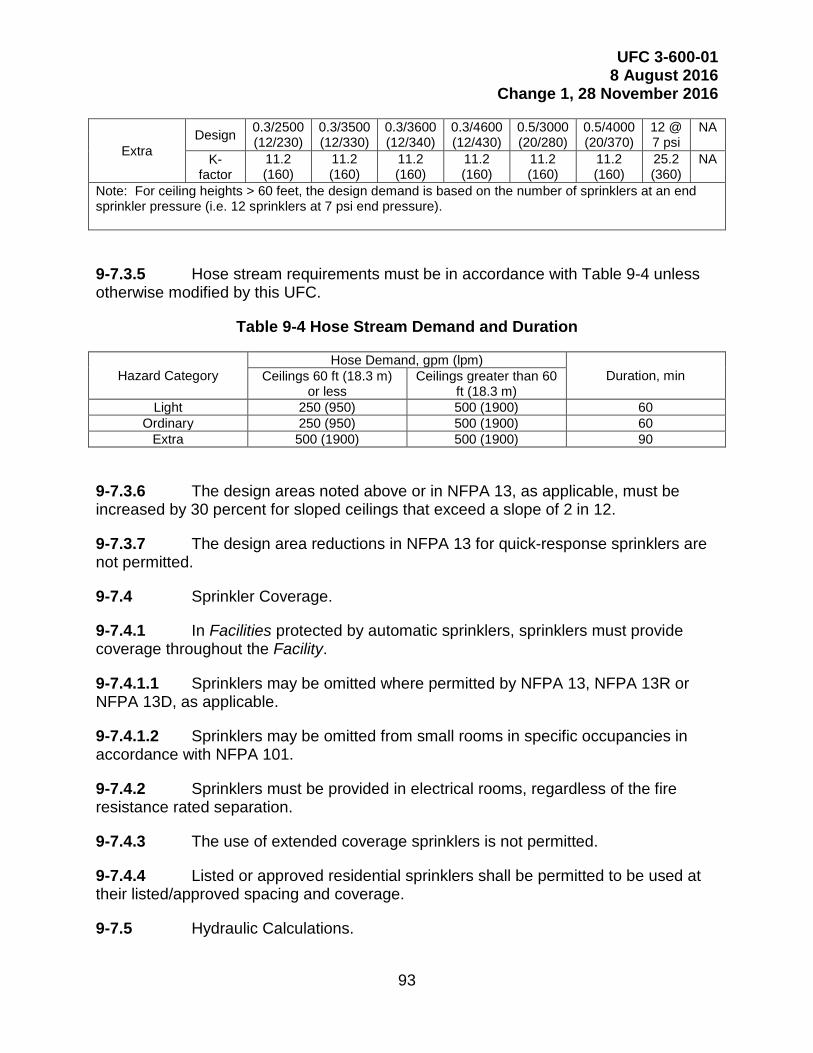
UFC 3-600-01 8 August 2016
Change 1, 28 November 2016
93
Extra Design 0.3/2500
(12/230) 0.3/3500 (12/330)
0.3/3600 (12/340)
0.3/4600 (12/430)
0.5/3000 (20/280)
0.5/4000 (20/370)
12 @ 7 psi
NA
K-factor
11.2 (160)
11.2 (160)
11.2 (160)
11.2 (160)
11.2 (160)
11.2 (160)
25.2 (360)
NA
Note: For ceiling heights > 60 feet, the design demand is based on the number of sprinklers at an end sprinkler pressure (i.e. 12 sprinklers at 7 psi end pressure).
Hose stream requirements must be in accordance with Table 9-4 unless 9-7.3.5otherwise modified by this UFC.
Table 9-4 Hose Stream Demand and Duration
Hazard Category Hose Demand, gpm (lpm)
Duration, min Ceilings 60 ft (18.3 m) or less
Ceilings greater than 60 ft (18.3 m)
Light 250 (950) 500 (1900) 60 Ordinary 250 (950) 500 (1900) 60
Extra 500 (1900) 500 (1900) 90
The design areas noted above or in NFPA 13, as applicable, must be 9-7.3.6increased by 30 percent for sloped ceilings that exceed a slope of 2 in 12.
The design area reductions in NFPA 13 for quick-response sprinklers are 9-7.3.7not permitted.
Sprinkler Coverage. 9-7.4
In Facilities protected by automatic sprinklers, sprinklers must provide 9-7.4.1coverage throughout the Facility.
Sprinklers may be omitted where permitted by NFPA 13, NFPA 13R or 9-7.4.1.1NFPA 13D, as applicable.
Sprinklers may be omitted from small rooms in specific occupancies in 9-7.4.1.2accordance with NFPA 101.
Sprinklers must be provided in electrical rooms, regardless of the fire 9-7.4.2resistance rated separation.
The use of extended coverage sprinklers is not permitted. 9-7.4.3
Listed or approved residential sprinklers shall be permitted to be used at 9-7.4.4their listed/approved spacing and coverage.
Hydraulic Calculations. 9-7.5

UFC 3-600-01 8 August 2016
Change 1, 28 November 2016
94
Sprinkler systems must be designed using hydraulic calculations. 9-7.5.1
Sprinkler systems permitted by this UFC to be supplied from the domestic 9-7.5.1.1plumbing may be designed using the pipe schedule method in NFPA 13.
The addition of no more than twenty sprinklers to an existing system is 9-7.5.1.2permitted to be designed using the pipe schedule based on the layout of the existing system.
Where the sprinkler system is supplied by interconnected risers, the 9-7.5.2sprinkler system must be hydraulically calculated using the hydraulically most demanding single riser. The calculations must not assume the simultaneous use of more than one riser.
Piping. 9-7.6
Galvanized piping is only permitted for deluge sprinkler systems, valve trim 9-7.6.1.1piping and drain piping exposed to the Facility exterior.
Black steel pipe must be used for the addition, repair or relocation of 9-7.6.1.2existing galvanized pipe in wet pipe, dry pipe or preaction systems.
Black steel pipe with furnace butt-welds (ASTM A53, Type F) must be used. 9-7.6.1.3
Electric-resistance-welded steel pipe is not permitted. 9-7.6.1.4
Piping 2-in. (50 mm) and less must be minimum schedule 40. Piping larger 9-7.6.2than 2-in. (50 mm) must be minimum schedule 10.
CPVC is permitted to be used in accordance with its listing. 9-7.6.3
For Navy/Marine projects, CPVC is only permitted for residential 9-7.6.3.1occupancies.
Plain end fittings with mechanical couplings and fittings that use steel 9-7.6.4gripping devices to bite into the pipe are prohibited.
Steel piping with wall thickness less than schedule 40 must not be 9-7.6.5threaded.
Saddle tees using rubber gasket fittings are only permitted when connecting 9-7.6.6to existing piping for additions or modifications. Saddle tees must use a connection method that completely wraps around the pipe.
Fittings, mechanical couplings, and rubber gaskets must be from the same 9-7.6.7manufacturer.

UFC 3-600-01 8 August 2016
Change 1, 28 November 2016
95
The use of flexible sprinkler hose with fittings intended for direct connection 9-7.6.8to sprinklers is not permitted.
Changes in pipe sizes must be made through tapered reducing pipe fittings. 9-7.6.9
Threaded fittings must use Teflon tape or manufacturer's approved joint 9-7.6.10compound.
Nitrogen Generation Systems. 9-7.7
Design the nitrogen generation system so all equipment is installed within 9-7.7.1the confines of the riser room with the exception of a connection for a manual gas analyzer.
Provide a nitrogen generation system that is capable of delivering a 9-7.7.2minimum of 98 percent nitrogen composition throughout all of the system piping within 14 days from the commencement of the inerting process.
The nitrogen generation system must be self-contained with "drop-in" 9-7.7.3operability with a simple one step direct connection of the nitrogen gas supply line to each zone.
The use of stand-alone compressed nitrogen bottle system is not permitted. 9-7.7.4
A process that involves continuous venting of the piping network is not 9-7.7.5permitted.
Any air maintenance device used in conjunction with the nitrogen 9-7.7.6generation system must be listed or approved for use on sprinkler systems.
Preaction Systems. 9-7.8
Preaction systems must utilize nitrogen complying with the "Nitrogen 9-7.8.1Generation Systems" section of this UFC, in lieu of air.
Dry Pipe Systems. 9-7.9
Dry pipe systems must utilize air or nitrogen. If nitrogen is used, the 9-7.9.1nitrogen generation system must comply with the requirements of this UFC.
The delivery of water from the dry pipe valve to the system test connection 9-7.9.2shall be in accordance with NFPA 13. Water delivery times must be measured starting at the normal nitrogen or air pressure on the system.
All rubber gasket grooved-end pipe fittings for dry pipe systems must be 9-7.9.3listed or approved for dry pipe systems.
System Requirements. 9-7.10

UFC 3-600-01 8 August 2016
Change 1, 28 November 2016
96
Provide a minimum clearance of 3 feet (915 mm) access to and in front of 9-7.10.1all equipment and 6-in. (150 mm) behind the equipment (e.g., control valves, backflow preventer, check valves, floor control valve assemblies, waterflow switches, etc.).
Thrust rod all pipe penetrations through the grade floor slab, unless flanged 9-7.10.2or welded joints are used throughout the below slab piping. All pipe penetrations through the grade floor slab shall be sleeved and sealed.
The QFPE shall coordinate with the Structural Engineer to determine the 9-7.10.3proper seismic design category for the project, in accordance with the IBC or ASCE guidelines. Seismic restraint is not required for Seismic design category A or B, except as otherwise required in this UFC.
Note: See UFC 3-310-04 for more information.
Drain and Test Connections. 9-7.10.4
Provide a permanently piped drain/test connection for each waterflow 9-7.10.4.1switch, including the waterflow switch for elevator power shunt.
Terminate all main drains and inspector’s test connections piping to the 9-7.10.4.2exterior of the Facility so it will not cause damage. Discharge to the exterior must not interfere with exiting from the Facility. Water discharge or runoff must not cross an exit or exit discharge path. Do not discharge to the roof.
Termination points interior to the building are permitted to be approved by 9-7.10.4.3the DFPE when exterior termination is not practical.
Provide concrete splash blocks at all drain and inspector’s test connection 9-7.10.4.4discharge locations if not discharging to a concrete surface. Splash blocks shall be large enough to mitigate erosion and shall not become dislodged during a full flow of the main drain. Ensure all discharged water drains away from the Facility and does not cause property damage.
Any drains, test connection pipe, etc., that penetrate the exterior wall must 9-7.10.4.5do so no greater than 2 feet (610 mm) above finished grade, and at no time below grade.
The drain/test connection must be piped to a location that will accept full 9-7.10.4.6flow and will not cause property damage when water is discharging.
Note: Comply with any applicable state or local environmental requirements pertaining to the handling of sprinkler discharge water.
Individual floor control assemblies are to be provided for each respective 9-7.10.5floor when there are three or more floor levels. Floor area meeting the IBC definition of a mezzanine is not considered a floor level when applying this requirement.

UFC 3-600-01 8 August 2016
Change 1, 28 November 2016
97
Provide a dedicated control valve assembly for piping serving rooms that 9-7.10.6require shunt-tripping of equipment power prior to or simultaneously to the application of water. Locate the control valve assembly outside of the area it serves in an easily accessible identified location.
Normally open valves required by NFPA 13, NFPA 13R or NFPA 13D to be 9-7.10.7supervised must be electrically supervised (i.e. tamper switch).
Normally closed valves required by NFPA 13, NFPA 13R or NFPA 13D to 9-7.10.8be supervised must be locked or sealed, unless otherwise required by this UFC.
Provide listed or approved sprinkler guards for sprinklers that are less than 9-7.10.97 feet (2.1 m) above finished floor (in unfinished areas) or subject to mechanical damage or can be grabbed from the floor level.
Sprinklers installed in any detention areas, regardless of the Facility 9-7.10.10occupancy classification, must be listed/approved institutional sprinklers.
Piping up to the backflow preventer, when the fire protection system is 9-7.10.11connected to a domestic water source, must be disinfected. Disinfection of all other aboveground fire protection system piping is not required.
Family Housing. 9-7.11
When sprinkler systems are provided in family housing in geographic locations having a 99.6% dry bulb temperature less than 32°F (0°C) per UFC 3-400-02 Engineering Weather Data, sprinkler piping is prohibited from being located in attic spaces or exterior walls (except for the incoming service). Locate upper story piping only in interior walls and utilize sidewall sprinklers.
9-8 WATER SPRAY SYSTEMS.
Water spray systems must comply with NFPA 15 and the "Fire Suppression Systems" requirements of this UFC.
9-9 FOAM SYSTEMS.
General. 9-9.1
Foam systems must comply with NFPA 11 and NFPA 16, and the "Fire 9-9.1.1Suppression Systems" requirements of this UFC, except as modified below.
For Army, AFFF is not permitted to be used for new systems. 9-9.1.2
New systems must use potable water or a water source that is supplied 9-9.1.3from a potable water system (i.e. a water storage tank that is filled from a potable water system). The use of saltwater, brackish or other untreated water source must be approved by the AHJ.

UFC 3-600-01 8 August 2016
Change 1, 28 November 2016
98
Foam storage tanks shall be labeled indicating vendor, model, type, and 9-9.1.4quantity of foam held within the tank via permanent sign.
Piping. 9-9.2
Foam solution piping must be schedule 40 steel pipe. 9-9.2.1
Foam concentrate piping must be stainless steel pipe with roll grooved 9-9.2.2fittings, welded joints and fittings, or flanged joints and fittings. If using welded joints and fittings, consideration must be given to the maintenance of the system and provide flanged joints at certain locations to allow for the ease of maintenance and equipment removal. Gasket material must be approved by the foam concentrate manufacturer.
Any concealed concentrate piping must use welded or flanged fittings. 9-9.2.3
Trim piping on all deluge valves, flow control valves, and alarm check 9-9.2.4valves must be brass.
Foam concentrate lines must be located above grade. 9-9.2.5
Aqueous Film-Forming Foam (AFFF) Concentrate. 9-9.3
Foam Systems that utilize AFFF must only use AFFF concentrate meeting 9-9.3.1Military Specification MIL-F-24385F.
AFFF concentrate must also be designated by the manufacturer as 9-9.3.2consisting of short chain C-6 fluorochemicals manufactured using a telomere-based process meeting the goals of the U.S. Environmental Protection Agency 2010/15 PFOA Stewardship Program.
Foam Concentrate Pumps. 9-9.4
Foam concentrate pumps must be used where the distance from the tank to the proportioner exceeds 50 feet (15.3 m), or the manufacturer recommended distance based on water supply, whichever is less.
Foam Concentrate Storage Tanks. 9-9.5
Foam concentrate storage tanks can be atmospheric or horizontal bladder. 9-9.5.1
Do not use vertical bladder tanks. 9-9.5.2
Atmospheric tanks must be translucent or opaque, double-walled, 9-9.5.3polyethylene.
Foam Concentrate Control Valves. 9-9.6
UFC 3-600-01 8 August 2016
Change 1, 28 November 2016
99
For automatic control of foam concentrate, provide valves listed or 9-9.6.1approved for use with foam concentrate.
Isolation control valves must be full port ball type with an operating handle 9-9.6.2that indicates the on/off position of the valve. Unit must be socket weld or flanged type. Valve body and ball must be 316 stainless steel complying with ASTM A351.
All foam system valves affecting foam delivery must be electrically 9-9.6.3supervised for correct position.
Foam Concentrate Spill Control. 9-9.7
Spill control must be provided around foam storage tank(s) to help prevent 9-9.7.1spilled/leaked foam concentrate from reaching any drains.
Spill control must consist of a minimum 4-in. (100 mm) high concrete berm 9-9.7.2or similar and sized for the full volume of the tank. Double-walled polyethylene tanks can qualify as acceptable spill control provided there are no taps or outlets in the sides or bottom of the tank.
Test Liquid. 9-9.8
Surrogate test liquid (alternate test liquid) is permitted to be used for initial acceptance testing and routine testing if the liquid and test method is approved by a DoD Component.
Foam Discharge. 9-9.9
Foam solution discharge for maintenance and testing purposes must be in accordance with local Installation environmental requirements.
9-10 STANDPIPE SYSTEMS.
General. 9-10.1
When required, standpipe systems must comply with NFPA 14 and the "Fire Suppression Systems" requirements of this UFC, except as modified below.
Residual pressure requirements for Facilities under 150 feet (45 m) in height may be met by fire department apparatus when hydraulic calculations demonstrate that fire department apparatus can provide the required pressure via the building fire department connection(s) with 150 psi at the FDC.
Class I Standpipe Systems. 9-10.2
Class I standpipe systems must be provided in all required exit stairs of 9-10.2.1Facilities four stories or more in height.
UFC 3-600-01 8 August 2016
Change 1, 28 November 2016
100
For Facilities less than four stories in height, Class I standpipe systems 9-10.2.2must be provided when the distance from any exterior door to any portion of the building (on any floor) exceeds 450 feet (140 m).
When required by this section, standpipes must be installed in all required 9-10.2.2.1exit stairs and on both side of horizontal exits.
Standpipes and hose valves must not encroach into the means of egress 9-10.2.3especially on stair landings.
Class II and III Standpipes. 9-10.3
Class II and III standpipes, as defined in NFPA 14 are not permitted.
9-11 DRY CHEMICAL EXTINGUISHING SYSTEMS.
Note: Fixed dry chemical extinguishing systems are appropriate for the protection of certain types of special occupancies, hazards, and facilities such as dip tanks, and other operations involving flammable liquids.
General. 9-11.1
Dry chemical extinguishing system must comply with NFPA 17 and the "Fire Suppression Systems" requirements of this UFC, except as modified below.
Limitations. 9-11.2
Dry chemical agents must not be used to protect sensitive electronics. Dry chemical extinguishing systems must not be used for the protection of cooking equipment.
9-12 WET CHEMICAL EXTINGUISHING SYSTEMS.
Note: Fixed wet chemical extinguishing systems are suitable for protection of certain types of special occupancies, hazards, and facilities, such as cooking surfaces, cooking exhaust systems, and dip tanks.
General. 9-12.1
Wet chemical extinguishing systems must comply with NFPA 17A and the "Fire Suppression Systems" requirements of this UFC, except as modified below.
Testing. 9-12.2
Testing must be performed by liquid discharge, utilizing the manufacturer’s recommended flushing concentrate, to demonstrate equal distribution of chemical and no leakage at pipe joints.

UFC 3-600-01 8 August 2016
Change 1, 28 November 2016
101
9-13 CLEAN AGENT FIRE EXTINGUISHING SYSTEMS.
Note: Clean agent fire extinguishing systems are suitable for protection of certain types of special occupancies, hazards, and facilities.
General. 9-13.1
Clean agent fire extinguishing systems must comply with NFPA 2001 and 9-13.1.1the "Fire Suppression Systems" requirements of this UFC, except as modified below.
Clean agent fire extinguishing systems are not permitted to substitute for 9-13.1.2required automatic sprinkler systems.
Fire extinguishing agents that have been identified for future manufacturing 9-13.1.3or use limitations must not be used, regardless if current installation is permitted by regulatory authorities in the country of application.\1\/1/
Requirements. 9-13.2
Provide stand-alone (not dependent upon the Facility fire alarm system for 9-13.2.1operation) control panels that are listed for releasing device service and monitored by the Facility fire alarm system.
Careful consideration must be given to compartment under/over-9-13.2.2pressurization during the discharge of total flooding clean agent systems. Pressure relieving vents, located near the finished ceiling, may be necessary to regulate rapid pressure changes during discharge. Comply with the manufacturer’s recommended procedures relative to enclosure venting.
Provide a manually activated exhaust system to facilitate the extraction of 9-13.2.3any remaining clean agent after the required hold time of the total flooding clean agent system.
The exhaust system can be integrated into the HVAC system for the 9-13.2.3.1enclosure, but in no case shall it be designed for less than six air changes per hour.
The manual activation switch must be located outside of the protected area. 9-13.2.3.2
Permanent signage must be provided indicating "Fire Suppression Exhaust 9-13.2.3.3System – Fire Department Use Only".
9-14 WATER MIST FIRE PROTECTION SYSTEMS.
Note: Water mist fire protection systems are suitable for protection of certain types of special occupancies, hazards, and facilities. Water mist fire protection systems are not a substitute for required automatic sprinkler systems.
General. 9-14.1

UFC 3-600-01 8 August 2016
Change 1, 28 November 2016
102
Water mist fire protection systems must comply with NFPA 750 and the 9-14.1.1"Fire Suppression Systems" requirements of this UFC, except as modified below.
Provide stand-alone (not dependent upon the Facility fire alarm system for 9-14.1.2operation) control panels that are listed for releasing device service and monitored by the Facility fire alarm system.
9-15 CARBON DIOXIDE SYSTEMS.
Note: Carbon dioxide (CO2) systems are normally effective against flammable liquid (Class B) and energized electrical (Class C) fires.
General. 9-15.1
Carbon dioxide system must comply with NFPA 12 and the "Fire 9-15.1.1Suppression Systems" requirements of this UFC, except as modified below.
New total flooding systems are not permitted in normally occupied areas. 9-15.1.2
Do not locate CO2 piping in any area where a pipe break or leak could 9-15.1.3make a normally occupied area untenable.
Careful consideration must be given to compartment under/over-9-15.1.4pressurization during the discharge of total flooding CO2 systems. Comply with NFPA 12 and the manufacturer’s recommended procedures relative to enclosure venting.
Provide a manually activated exhaust system to facilitate the extraction of 9-15.1.5any remaining CO2 after the required holding time of the total flooding CO2 system. The exhaust system can be integrated into the HVAC system for the enclosure but in no case shall it be designed for less than six air changes per hour. The manual activation switch must be located outside of the protected area.
9-16 HALON 1301 SYSTEMS.
General. 9-16.1
Installation of a new Halon 1301 system is prohibited except by special approval of \1\Service Signature Authority/1/.
Halon Turn-In Procedures. 9-16.2
For projects involving the demolition of existing Halon 1301 systems, refer to the following for turn-in requirements: http://www.dla.mil/aviation
UFC 3-600-01 8 August 2016
Change 1, 28 November 2016
103
9-17 PORTABLE FIRE EXTINGUISHERS.
General. 9-17.1
General purpose portable fire extinguishers are not required when the Facility is provided with complete automatic sprinkler protection and a fire alarm system in accordance with this UFC.
Portable fire extinguishers must be provided in all Medical Facilities, 9-17.1.1regardless of the DoD Component.
Location. 9-17.2
When provided, portable fire extinguishers must be located in accordance 9-17.2.1with NFPA 10.
If provided in Electronic Equipment Areas, clean agent type portable fire 9-17.2.2extinguishers must be used.
Portable fire extinguishers utilizing carbon dioxide (CO2) are only permitted 9-17.2.3to be used in enclosed rooms if they exceed 1,000 ft2 (92.9 m2).
Mounting. 9-17.3
In finished areas, recessed or semi-recessed enclosed cabinets must be 9-17.3.1provided for extinguishers.
In unfinished areas (such as warehouses and industrial areas), wall 9-17.3.2brackets or enclosed cabinets must be provided for fire extinguishers.
9-18 FIRE ALARM SYSTEMS.
General. 9-18.1
Fire alarm systems (detection and notification) must comply with the 9-18.1.1applicable provisions of NFPA 72 and the ABA, except as modified by this UFC.
Buildings or portions of the building that are not required to comply with 9-18.1.1.1ABA/ABAAG, must still comply with NFPA 72.
Fire alarm systems must be independent, stand-alone systems that are not 9-18.1.2an integral part of a security, energy monitoring and control system (EMCS), or other system.
The fire alarm system must be combined with a Facility mass notification 9-18.1.2.1system or with a combination Facility mass notification and public address system when mass notification is required by UFC 4-010-01. The fire alarm system, or combined

UFC 3-600-01 8 August 2016
Change 1, 28 November 2016
104
Facility mass notification and fire alarm system, may be separate from a public address system.
The fire alarm system is permitted to be connected to the EMCS or similar 9-18.1.2.2system to affect shutdown of HVAC units that require shutdown according to UFC 4-010-01 and UFC 4-021-01, but are otherwise not required to be controlled by the fire alarm system.
Fire alarm systems may be connected to security systems or an EMCS for 9-18.1.2.3monitoring purposes only, but must in no way rely on those other systems for operation or reporting.
Wireless interior fire alarm systems and devices are not permitted. 9-18.1.3
Plans and Calculations. 9-18.2
For new or modified systems, construction (shop) drawings and calculations must be prepared by an individual that has obtained National Institute for Certification in Engineering Technologies, Fire Alarm Systems, Level III certification, at a minimum. The QFPE must review the shop drawings, calculations and material submittals. The shop drawings must bear the Review Stamp of the QFPE prior to submitting the fire alarm system shop drawings to the DFPE.
For Army, construction (shop) drawings and calculations must be prepared by, or prepared under the immediate supervision, of the QFPE. The QFPE must affix their professional engineering stamp with signature to the shop drawings, calculations and material data sheets, indicating approval prior to submitting the fire alarm system shop drawings to the DFPE. The QFPE must monitor the installation of the fire alarm system and certify in writing that the fire alarm system has been constructed and operates as intended in the design plans and specifications.
Fire Alarm Reporting System. 9-18.3
Fire Alarm Reporting Systems must conform to NFPA 72 and NFPA 70. 9-18.3.1
The Facility fire alarm system must be connected to the Fire Alarm 9-18.3.2Reporting System.
The following signals, at a minimum, must be transmitted via the Fire Alarm 9-18.3.3Reporting System:
a. Alarm signal by device type (e.g., waterflow, manual pull station, sleeping room smoke detector).
b. General supervisory signal. c. General trouble signal.

UFC 3-600-01 8 August 2016
Change 1, 28 November 2016
105
New exterior fire alarm boxes are not required at DoD Installations, nor is it 9-18.3.4required to replace existing boxes that are not needed for the transmission of automatic alarms.
Fire Alarm Reporting Systems must provide the following where applicable: 9-18.3.5
a. Transmission of coded signals to fire department headquarters or other central locations;
b. Permanent record of alarm signal, time, and date; c. Automatic supervision of alarm initiating circuits; d. Automatic testing of radio signaling devices; e. A dedicated transmitter that will transmit alarm, supervisory and trouble
signals for each Facility; and
f. Transmitters must be listed or approved for use with the existing Fire Alarm Reporting System.
Control Panels. 9-18.4
The fire alarm control panel must be analog/addressable, site 9-18.4.1programmable panel, and must have, or be capable of, the following:
a. The ability to store at least 400 events in the history log. These events must be stored in a non-volatile memory and remain in the memory until the memory is downloaded or cleared manually.
b. Resetting of the control panel must not clear the memory from being retrieved on the integral LCD display.
c. An integral LCD 80 character (minimum) alphanumeric display. d. Provide all smoke detectors connected to the FACP with an adjustable
alarm verification feature. Initially set the alarm verification at 20 seconds. Existing fire detection systems that are controlled by Facility management, energy or utility management systems are permitted to remain.
A conventional control panel is permitted to be used for systems monitoring 9-18.4.1.1sprinkler system alarm, supervisory and trouble conditions only as permitted by NFPA 101 (e.g. a warehouse).
In new construction or major Renovations, the control panel cabinets and 9-18.4.2remote annunciator cabinet located in finished areas must be recessed or semi-recessed. Associated battery cabinets shall be recessed or installed in a closet, electrical room, or other, similar room.

UFC 3-600-01 8 August 2016
Change 1, 28 November 2016
106
Locate the control panel and supplemental control panels in a year-round 9-18.4.3environmentally conditioned space within the Facility that complies with the environmental conditions required in the panel approval or listing.
Note: Environmental condition values (temperature and humidity) are taken from UFC 3-400-02.
If the fire alarm control panel is not located at the designated primary 9-18.4.4entrance, provide a remote annunciator at the designated primary entrance unless directed otherwise by the contract documents. Provide remote annunciator with control functions the same as the main control panel. Control functions must be accessible only by user code or secured behind a locked panel.
Detection. 9-18.5
Note: Detection systems, especially smoke detection systems, require significant maintenance. It is critical that the required detectors are properly installed and maintained. Providing detectors in locations that are not required increases the already high maintenance costs of alarm systems and strains the maintenance program for critical detection systems. If a Facility warrants protection and criteria does not require detection, protection must be accomplished by a wet pipe sprinkler system. Wet pipe sprinklers provide superior protection with little maintenance.
General. 9-18.5.1
Fire detection systems must be provided in areas required by this UFC or 9-18.5.1.1where required by NFPA standards and must be limited to these applications unless an Exemption is approved\1\/1/.
The area of protection for smoke detection devices permitted by NFPA 72 9-18.5.1.2must be reduced by 50 percent where destratification (ceiling) fans are used (e.g., this may require additional smoke detectors for that area being protected).
The above reduction is in addition to any other reductions in spacing 9-18.5.1.3required by NFPA 72 (e.g., high ceiling, high air-flow).
Requirements. 9-18.5.2
Detection systems must be arranged to alert Facility occupants and to transmit an alarm signal via a Fire Alarm Reporting System.
Notification. 9-18.6
Notification must be provided throughout the entire Facility where required 9-18.6.1by NFPA 101 or when automatic detection or suppression systems are required by this UFC.

UFC 3-600-01 8 August 2016
Change 1, 28 November 2016
107
Where a mass notification system is required, fire alarm notification must be 9-18.6.2via a voice evacuation system and must serve as the method of notification for the mass notification system.
Audible and Visible Notification Appliances. 9-18.6.3
a. Provide a minimum of one notification appliance circuit per floor. Each notification appliance circuit must include 25 percent spare capacity.
b. Sleeping room speakers must produce a 520 Hz signal temporal three (T3) signal for fire in accordance with NFPA 72.
c. Provide a 520 Hz signal temporal four (T4) signal for carbon monoxide in accordance with NFPA 720 when required by the "Carbon Monoxide (CO) Detection" section of this UFC.
d. The provision of a sounder base does not negate the requirement of the Facility’s audible notification appliances for each sleeping room.
e. The performance requirements for audible notification shall be met with all doors, fire shutters, movable partitions, and other similar devices closed.
f. Visible notification must be provided in all normally occupied, public and common use areas (e.g., break rooms, corridors, auditoriums or conference rooms).
g. Visible notification must be provided in all normally unoccupied areas (such as mechanical rooms, electrical rooms, janitor rooms, storage areas, communication closets and other similar spaces) greater than 900 ft2 (84 m2).
h. Visible notification is required in any normally unoccupied area where the ambient noise is loud enough to require hearing protection (e.g., compressor room).
i. Visible notification must be provided in all offices that are designed for, or may contain, more than four persons at any one time. For Air Force, visual notification must be provided in all offices that are designated for, or may contain, two or more persons at any one time.
Note: This shall be determined by the furniture plan. If four or more chairs with work surfaces are assigned to the room, visible notification is required. For Air Force if two or more chairs (with or without work surfaces) are assigned to the room, visual notification is required. j. Visible notification is not required in single person offices, unless the
office is assigned to a person with a hearing impairment that would require a visible notification appliance.

UFC 3-600-01 8 August 2016
Change 1, 28 November 2016
108
k. Visible notification is not required in bathrooms serving single person offices, unless the office is assigned to a person with a hearing impairment that would require a visible notification appliance.
l. Visible notification appliances must be provided with a clear lens marked "Alert". The use of "Fire" is not permitted.
Mass Notification System (MNS). 9-18.6.4
Refer to UFC 4-021-01.
Voice Message. 9-18.6.5
For systems using voice evacuation or combined with the mass notification system, the default fire alarm voice evacuation message must be a female voice and state the following:
(Temporal 3 Alert Tone) "May I have your attention please. May I have your attention please. A fire emergency has been reported in the building. Please leave the building by the nearest exit or exit stairway. Do not use the elevators". <provide a 2 second pause> "May I have your attention please..." (repeat the message).
Installations with formally established and approved/published in accordance with the Service/Agency policy standard signals and messages are permitted to utilize those standard signals and messages. Installations without formally established signals and message standards must follow the default guidance in "Appendix E" of this UFC. The general format must be a specific alert signal tone(s) followed by a voice announcement(s) and then repeats the cycle for a specific number of cycles or continuously as appropriate for the message.
Note: For single-story Facilities, delete "or exit stairway. Do not use the elevators" from the voice message.
Initiating Devices. 9-18.7
Sprinkler Waterflow. 9-18.7.1
Provide a separate address for each sprinkler waterflow switch.
Sprinkler System Supervisory Air or Gas. 9-18.7.2
Monitor high and low air or gas pressure on dry pipe and preaction systems on a per riser room basis as a supervisory function with the Facility fire alarm system.
Valve Tamper. 9-18.7.3

UFC 3-600-01 8 August 2016
Change 1, 28 November 2016
109
No more than five adjacent valve tamper switches within the same room are permitted to be monitored by the same addressable device or supervisory circuit.
Manual Pull Station. 9-18.7.4
Provide addressable double-action type manual pull stations with 9-18.7.4.1mechanical reset features. If the manual pull station requires a key for reset, it must be the same key as required for the fire alarm control panel.
Conventional single-action manual pull stations are permitted in hazardous 9-18.7.4.2areas, wet and damp locations, and other areas where specialty listings are required. Where a conventional manual pull station is used, it shall be provided with a separate address.
Smoke Detection. 9-18.7.5
Provide 24 Vdc photoelectric smoke detectors in all sleeping rooms and 9-18.7.5.1duty rooms located in business or other occupancies. Not applicable to inpatient sleeping rooms of healthcare occupancies.
Upon detection of smoke, an audible signal must be activated in the 9-18.7.5.2respective sleeping room, dwelling unit/suite or duty room, send a distinct signal to the Facility fire alarm control panel, if required by other sections of this UFC, and to the Installation fire reporting system, but not activate the Facility notification appliances.
See Chapter 4 for Open Bay Personnel Housing. 9-18.7.5.3
The audible signal shall be low frequency as required by NFPA 72. 9-18.7.5.4
Under-floor Smoke Detector Identification. 9-18.7.6
When under-floor smoke detectors are provided, provide a framed CAD drawn floor plan showing the location of the devices in the room and their corresponding address. Locate a single framed drawing of the location of the smoke detectors outside of the space and adjacent to the main entrance.
Power Disconnect. 9-18.8
For disconnecting power supplies, provide listed control relays located within 3 feet (915 mm) of the shunt trip breaker. Operation of relay must be controlled by a listed fire alarm control unit. Relay must function within the voltage and current limitations of the fire alarm control unit. Relay contacts must be listed for the connected load.
Wiring, Circuits and Conduit. 9-18.9
Class B pathways for addressable detection, notification, and signaling line 9-18.9.1circuits meet all minimum/necessary DoD performance requirements.

UFC 3-600-01 8 August 2016
Change 1, 28 November 2016
110
All conductors must be installed in conduit (EMT minimum). 9-18.9.2
Conductors. 9-18.9.3
Pull all conductors splice free; conductors shall be continuous from device 9-18.9.3.1to device. The use of wire nuts, crimped connectors, or twisting of conductors is prohibited.
Run all wiring to and within control panels in the vertical or horizontal plane, 9-18.9.3.2make all turns at 90 degree angles, and tightly bundle, wrap, and identify all conductors individually with permanent markings. Conductor markings shall be printed labels, permanently affixed to the conductor via shrink wrap.
Conductor Type. 9-18.9.4
Wiring may be solid copper or stranded as permitted by NFPA 70. 9-18.9.4.1
All signaling line circuits must be minimum 18 AWG. Initiating device and 9-18.9.4.2notification appliance circuits must be minimum 16 AWG.
Initiating device circuits used for optical flame detection devices must use 9-18.9.4.3shielded cable.
Device Termination. 9-18.9.5
All devices must have screw terminals. Where devices are only provided with pigtails from the manufacturer, pigtails must be landed on terminal strips mounted within the junction box.
Conductor Terminations. 9-18.9.6
All terminations must be at a terminal strip or the device screw terminals. Terminal strips are only permitted where direct connection to a device is not possible. (e.g., pigtails off a rate-compensating heat detector).
Identification. 9-18.9.7
All conduit, junction/back boxes, covers and couplings, when provided, 9-18.9.7.1must be factory painted red in unfinished areas (e.g., above ceilings, mechanical rooms, etc.).
All conduit, junction/back boxes, covers and couplings, when provided, are 9-18.9.7.2permitted to be painted to match the room finishing in finished areas. The inside cover of the junction box must be identified as "Fire Alarm" and the conduit must have painted red bands 3/4-in. (20 mm) wide at 20 feet (6 m) intervals and on both sides of all floor, wall, and ceiling penetrations.
Surge Suppression. 9-18.10

UFC 3-600-01 8 August 2016
Change 1, 28 November 2016
111
Provide surge suppression (SPD) for all signaling line circuits, indicating 9-18.10.1device circuits, or notification appliance circuits that leave or enter a Facility’s exterior enclosure.
SPD must be provided at the first location where connections are made that 9-18.10.2is close to where the circuit enters or leaves the Facility, prior to connection to any other devices when feasible.
SPD is not required for devices connected directly to the Facility exterior 9-18.10.3when the Facility itself is provided with lightning protection (i.e. an electric bell or speakers mounted on the exterior wall of the Facility.)
Power. 9-18.11
Provide primary power in accordance with UFC 3-520-01. This includes the 9-18.11.1provision of a lock-on circuit breaker.
Provide SPD on all 120 Vac circuits to control panels, subpanels, 9-18.11.2transmitters, amplifier panels, and booster panels. SPD shall have both a UL 1449 and UL 1283 listing and shall be located in an adjacent hinged terminal box.
Secondary Power. 9-18.11.3
Provide rechargeable batteries per NFPA 72 to operate the fire alarm system under supervisory conditions for 48 hours and all alarm devices for an additional 15 minutes. Where the fire alarm system also serves as a mass notification system, refer to UFC 4-021-01 for additional requirements.
Releasing Control Panels. 9-18.12
In addition to the requirements specified above for fire alarm control panels, 9-18.12.1panels used for control or release of fire suppression systems must be listed by a NRTL for releasing service.
Provide a separate releasing panel independent of the Facility fire alarm 9-18.12.1.1system panel to activate the system.
A combined fire alarm/releasing panel is permitted for small Facilities with 9-18.12.1.2the approval of the DFPE.
Electronic solenoids used for release of the suppression system must be 9-18.12.2listed by a NRTL for use with both the releasing panel and the suppression equipment.
Provide rechargeable batteries per NFPA 72 to operate the releasing panel 9-18.12.3under supervisory conditions for 48 hours and alarm conditions for an additional 15 minutes. Include the full current draw of the solenoid in the battery calculations.

UFC 3-600-01 8 August 2016
Change 1, 28 November 2016
112
When more than one panel is used, each panel must be monitored 9-18.12.4independently by the Facility fire alarm control panel.
Locate the panel adjacent to, but not in, the hazard/area served. The 9-18.12.5releasing panel and supplemental control panels must be located in a year-round environmentally conditioned space that complies with the environmental conditions required in the listing.
When required, pre-discharge and discharge alarms must consist of audible 9-18.12.6and visible notification appliances that are different than the Facility fire alarm system notification appliances.
9-19 CARBON MONOXIDE (CO) DETECTION.
General. 9-19.1
Provide carbon monoxide detection in facilities with combustible fuel 9-19.1.1burning equipment (e.g., air handling units, heaters, stoves, fireplaces).
Carbon monoxide detection must conform to the requirements of NFPA 720 9-19.1.2and the manufacturer’s requirements, except as modified by this UFC.
Carbon monoxide detectors must be powered by the fire alarm control 9-19.1.3panel (i.e. 24 Vdc). Where a fire alarm system is not provided, 120 Vac detectors are permitted.
Installation. 9-19.2
Detectors must be located in each room/space where the fuel burning 9-19.2.1appliances(s) are located.
At least one detector must be located in each HVAC zone served by a 9-19.2.2separate air handler in the Facility.
For Army projects, in lieu of locating a detector in each HVAC zone: for each HVAC system served by a separate air handler, locate one detector in the room with the main system fan and a second detector in the zone with the largest supply air flow.
Notification. 9-19.3
Where a fire alarm voice evacuation system is provided, activation of a 9-19.3.1carbon monoxide detection device must initiate a unique voice notification message.
The alert signal portion of the voice alarm message for carbon monoxide 9-19.3.1.1detection must be a 520 Hz temporal 4 (T-4) signal. The alert signal must repeat twice before the voice announcement.

UFC 3-600-01 8 August 2016
Change 1, 28 November 2016
113
A sample message is as follows: (Temporal 4 Alert Tone) 9-19.3.1.2"Attention….Attention….Carbon monoxide has been detected in the building. Please leave the building by the nearest exit." (Temporal 4 Alert Tone)
Where a voice evacuation system is not provided, activation of a carbon 9-19.3.2monoxide detector must initiate an audible alarm distinctly different from other audible alarm signals in the Facility. Distinct visible notification is not required.
When part of the fire alarm system, activation of a carbon monoxide 9-19.3.3detector shall send a separate "carbon monoxide detector" alarm signal to the Fire Alarm Reporting System.
Sleeping room audible appliances must provide a 520 Hz temporal 4 (T4) 9-19.3.4signal for carbon monoxide in accordance with NFPA 720. The provision of a sounder base does not negate the requirement of the Facility’s audible notification appliances for each sleeping room.”
9-20 SMOKE CONTROL SYSTEM
General. 9-20.1
Design must be in accordance with NFPA 92. 9-20.1.1
Design parameters must be documented and be based on industry 9-20.1.2standards of practice, such as the SFPE Handbook of Smoke Control Engineering. Other source documents, such as peer-reviewed research articles, may be used with approval of the DFPE.
Controls must be designed and listed as required by NFPA 92. 9-20.1.3
Fire alarm control unit must be ANSI/UL 864, category UUKL listed. 9-20.1.4
HVAC controls must be ANSI/UL 864, category UUKL listed where required 9-20.1.5by NFPA 92.
Fire alarm system sequence of operations matrix must include all automatic 9-20.1.6and firefighter's smoke control station functions.
Design must include a preliminary test plan. 9-20.1.7
Installation. 9-20.2
Prior to installation and programming, provide a single submittal that 9-20.2.1includes all smoke control system components.
Submittal must document all aspects of integration between the involved 9-20.2.2systems and trades, such as the interface between the fire alarm and HVAC systems.

UFC 3-600-01 8 August 2016
Change 1, 28 November 2016
114
Documentation must include the physical interface and logic interface. 9-20.2.3Physical interface description must include location of control devices and wiring diagrams for all components. Logic interface description must include the complete sequence of operations, from input to final output.
Submittal must include an updated test plan, tailored to the specific devices 9-20.2.4and arrangements to be installed. Test plan must include all proposed test procedures.
Testing. 9-20.3
Testing must be in accordance with NFPA 92. 9-20.3.1
Individual components must be tested in accordance with the relevant UFC. 9-20.3.2For example, fire alarm system components must be tested in accordance with UFC 3-600-01 and NFPA 72. Fans must be tested in accordance with Air Movement and Control Association (AMCA) Publication 203.
Submit a revised test plan that incorporates any as-built conditions that 9-20.3.3differ from the smoke control submittal, prior to the start of any acceptance testing.

UFC 3-600-01 8 August 2016
Change 1, 28 November 2016
115
MEANS OF EGRESS CHAPTER 10
10-1 GENERAL.
Requirements. 10-1.1
Comply with NFPA 101 for all components and features related to means of egress. IBC must not be used for any means of egress features, except as specifically noted below.
Accessible Means of Egress. 10-1.2
Comply with NFPA 101 for accessible means of egress.
10-2 MEANS OF EGRESS MARKING.
Requirements. 10-2.1
Incandescent or fluorescent fixtures are not permitted for new installation or 10-2.1.1replacement of fixtures.
Use of the graphic emergency exit symbols with and without directional 10-2.1.2arrows (NFPA 170 or Host Nation equivalents) in lieu of the text “EXIT” is permitted.
In locations outside the Unites States and its territories and possessions, 10-2.1.3additional markings may be required to remain consistent with local national standards; colors must be consistent with local national standards, and bilingual signs are recommended.
Radioluminous Exit Signs. 10-2.2
Radioluminous exit signs are not permitted in DoD Facilities.
Photoluminescent Exit Signs and Markings. 10-2.3
Photoluminescent exit signs and egress path markings are permitted and 10-2.3.1must be designed and installed per the requirements of NFPA 101. The charging light source must be continually illuminated at all times with normal power. The charging light source must not be on a switched circuit.
The illumination source must be energized at all times during building 10-2.3.2occupancy. Such lighting must not be controlled by automatic timers, automatic sensors including area occupancy sensors, or accessible manual switches. Controls for such lighting must be accessible only to authorized personnel.

UFC 3-600-01 8 August 2016
Change 1, 28 November 2016
116
10-3 OCCUPANT LOAD.
Occupant load factors. 10-3.1
Occupant load must be calculated in accordance with NFPA 101, except as noted in Table 10-1 below:
Table 10-1 Supplemental Occupant Load Factors
Use Occupant Load Factor (sf/person)
Waiting spaces other than those in theaters and assembly occupancies where persons are admitted to the building at times when seats are not available
15 net
Exhibit galleries, museums 30 net
Courtrooms, hearing rooms – other than fixed seating areas
40 net
Conference rooms with tables and chairs 15 net
Community shelters (e.g., spaces designated for ‘shelter in place’ for tornado, hurricane, disaster recovery, or similar)
20 net
Recreation – indoor tennis courts 50 gross
Recreation – squash, racquetball 4 per court
Locker rooms 50 gross or maximum anticipated number, whichever is
higher
Bowling centers 5 persons per lane plus 7 net for additional areas
Dormitories (bunks) 50 gross
Mechanical, electrical, other building equipment spaces 500 gross
IT equipment rooms including those with small work areas in accordance with NFPA 75 or telecommunications rooms in accordance with NFPA 76
300 gross
Manufacturing areas 200 gross
Parking garages 200 gross
Telecommunications buildings (standalone) 500 gross
Aircraft hangars – aircraft storage and servicing areas 500 gross
Magazines and bunkers Maximum anticipated number of personnel

UFC 3-600-01 8 August 2016
Change 1, 28 November 2016
117
Maximum occupant load. 10-3.2
The maximum occupant load for any space or Facility must not exceed one person per 7 ft2 (0.65 m²) of net floor space or the maximum capacity of the required egress components, whichever is less.
10-4 STAIR TO ROOF ACCESS.
Stair to roof access must be in accordance with the IBC.

UFC 3-600-01 8 August 2016
Change 1, 28 November 2016
118
This Page Intentionally Left Blank
UFC 3-600-01 8 August 2016
Change 1, 28 November 2016
119
ACCESSIBILITY CHAPTER 11
11-1 GENERAL.
For fire protection requirements, no changes to the IBC Chapter 11 provisions.
INTERIOR ENVIRONMENT CHAPTER 12
12-1 GENERAL.
For fire protection requirements, no changes to the IBC Chapter 12 provisions.
ENERGY EFFICIENCY CHAPTER 13
13-1 GENERAL.
For fire protection requirements, no changes to the IBC Chapter 13 provisions.
EXTERIOR WALLS CHAPTER 14
14-1 GENERAL.
For fire protection requirements, no changes to the IBC Chapter 14 provisions.
ROOF ASSEMBLIES AND ROOFTOP STRUCTURES CHAPTER 15
15-1 ROOF COVERINGS.
Use roof coverings approved and listed by a NRTL. Class C roof coverings, as defined in the UL Roofing Materials and Systems Directory are only permitted for single and duplex style housing and Facilities less than or equal to 5,000 ft2 (465 m2).
15-2 ROOF DECK ASSEMBLIES.
General. 15-2.1
For non-sprinklered Facilities or Facilities less than 8,000 ft2 (743 m2), roof 15-2.1.1deck assemblies must be FM Class I approved, or UL-listed as fire classified or equal listing or classification by an NRTL.
UFC 3-600-01 8 August 2016
Change 1, 28 November 2016
120
Where a non-combustible roof is installed over an existing combustible roof, 15-2.1.2the existing combustible roof materials must be removed or the space between the existing and new roof must be protected as a combustible concealed space per NFPA 13.
Note: FM Class I or II ratings and UL "Fire Classified" ratings are measures of the resistance, of the entire roof assembly, to ignition from exposure to a fire within the building, heating the underside of the roof deck. These two ratings cannot be equated and are not interchangeable.
Where the HVAC or similar equipment is located on the existing roof and 15-2.1.3not removed, the space between the existing and new roof must be protected as and considered a combustible concealed space per NFPA 13.
Roof top solar photovoltaic (PV) panels must be mounted to facilitate 15-2.1.4application of water from fire department vehicles to fires on the roof deck surface. Arrangement of PV panels must meet the requirements of UFC 3-440-01.
STRUCTURAL DESIGN CHAPTER 16
16-1 GENERAL.
For fire protection requirements, no changes to the IBC Chapter 16 provisions.
SPECIAL INSPECTIONS AND TESTS CHAPTER 17
17-1 GENERAL.
For fire protection requirements, no changes to the IBC Chapter 17 provisions.
SOILS AND FOUNDATIONS CHAPTER 18
18-1 GENERAL.
For fire protection requirements, no changes to the IBC Chapter 18 provisions.

UFC 3-600-01 8 August 2016
Change 1, 28 November 2016
121
CONCRETE CHAPTER 19
19-1 GENERAL.
For fire protection requirements, no changes to the IBC Chapter 19 provisions.
ALUMINUM CHAPTER 20
20-1 GENERAL.
For fire protection requirements, no changes to the IBC Chapter 20 provisions.
MASONRY CHAPTER 21
21-1 GENERAL.
For fire protection requirements, no changes to the IBC Chapter 21 provisions.
STEEL CHAPTER 22
22-1 GENERAL.
For fire protection requirements, no changes to the IBC chapter 22 provisions.
WOOD CHAPTER 23
23-1 FIRE RETARDANT TREATED (FRT) WOOD.
Conform to the requirements of IBC for permitted use of FRT wood. FRT plywood must not be used in any part of the roof or roofing system.
Note: Do not use fire-retardant-treated wood in lieu of required noncombustible materials. Fire-retardant-treated wood shall not be considered noncombustible.
GLASS AND GLAZING CHAPTER 24
24-1 GENERAL.
For fire protection requirements, no changes to the IBC Chapter 24 provisions.

UFC 3-600-01 8 August 2016
Change 1, 28 November 2016
122
GYPSUM BOARD, GYPSUM PANEL PRODUCTS AND PLASTER CHAPTER 25
25-1 GENERAL.
For fire protection requirements, no changes to the IBC Chapter 25 provisions.
PLASTIC CHAPTER 26
26-1 GENERAL.
For fire protection requirements, no changes to the IBC Chapter 26 provisions.
ELECTRICAL CHAPTER 27
27-1 GENERAL.
For fire protection requirements, no changes to the IBC Chapter 27 provisions.
MECHANICAL SYSTEMS CHAPTER 28
28-1 AIR HANDLING.
General. 28-1.1
Fire protection features for air handling, heating, ventilation, and exhaust systems, such as duct smoke detectors, fire dampers and smoke dampers, must comply with the requirements of NFPA 90A, except as modified by this UFC.
Duct smoke detectors shall not be required where air distribution systems are incapable of spreading smoke beyond the enclosing walls, floors and ceilings of the room or space in which the smoke is generated.
Plenums. 28-1.2
Plenums may be used as an integral part of an air handling system only if they conform to the requirements of NFPA 90A. Under no circumstances may combustible materials be located within the plenum space. Electrical wiring passing through the space, including telephone and communication wiring must be plenum rated or must be in metal conduit.

UFC 3-600-01 8 August 2016
Change 1, 28 November 2016
123
Rooms or areas that form a plenum space or that are used as a plenum must not be occupied for any purpose except during repairs or maintenance operations to the air handling equipment.
Computer Room Air Conditioning (CRAC). 28-1.3
CRAC units must not automatically shut down if electronic equipment 28-1.3.1remains energized and heat generated in the room will be sufficient to activate sprinkler heads.
PLUMBING SYSTEMS CHAPTER 29
29-1 GENERAL.
For fire protection requirements, no changes to the IBC Chapter 29 provisions.
ELEVATORS AND CONVEYING SYSTEMS CHAPTER 30
30-1 GENERAL.
For fire protection requirements, no changes to the IBC Chapter 30 provisions.
Comply with requirements of the "Elevators" section of this UFC.
SPECIAL CONSTRUCTION CHAPTER 31
31-1 GENERAL.
For fire protection requirements, no changes to the IBC Chapter 31 provisions.
ENCROACHMENTS INTO THE PUBLIC RIGHT-OF-WAY CHAPTER 32
32-1 GENERAL.
For fire protection requirements, no changes to the IBC Chapter 32 provisions.
SAFEGUARDS DURING CONSTRUCTION CHAPTER 33
33-1 GENERAL.

UFC 3-600-01 8 August 2016
Change 1, 28 November 2016
124
For fire protection requirements, no changes to the IBC Chapter 33 provisions.

UFC 3-600-01 8 August 2016
Change 1, 28 November 2016
125
EXISTING FACILITIES CHAPTER 34
34-1 GENERAL.
Minimum Requirements. 34-1.1
Facilities, as they exist, must meet the requirements of NFPA 101, for existing occupancies. Facilities that do not meet the requirements of NFPA 101 for existing occupancies must conform to one of the following:
a. Upgrade the deficiency to meet the existing occupancy requirements, or
b. Establish management protocols to provide a level of life safety equivalent to that required by NFPA 101 for existing occupancies, until an upgrade project can be completed. Management protocols must be in writing and approved by the AHJ.
Note: For the Air Force, the Component management protocol approval process is in Air Force Instruction 32-10141 Planning and Programming Fire Safety Deficiency Correction Projects.
Work in Existing Facilities. 34-1.2
Conform to the requirements of the Building Rehabilitation chapter of NFPA 34-1.2.1101 for design and construction projects in existing buildings including the following categories of rehabilitation work; Addition, Repair, Renovation, Modification, Reconstruction and Change of Use or occupancy classification.
Where multiple categories of rehabilitation work are planned as part of a 34-1.2.2single project, identify each category of rehabilitation work to be performed, including what is required and what will be provided, within each one.
Phasing of construction and demolition operations must be planned so that 34-1.2.3the integrity of fire-rated separations, smoke-tight boundaries, means of egress, exit enclosures, and vertical openings are maintained to the highest level possible.
The phasing plan must ensure that obstruction of the means of egress is 34-1.2.3.1avoided or minimized.
If exits are obstructed during construction, provide alternate means of 34-1.2.3.2egress and exit routes during each phase of construction and identify the alternate routes on the construction drawings as part of the phasing plan(s).
Minimize, to the extent possible, any impairments or disruptions to active 34-1.2.4fire protection features. Delineate phasing of construction to ensure that installations of new features (or systems) or modifications to existing ones are expedited.

UFC 3-600-01 8 August 2016
Change 1, 28 November 2016
126
Where possible, maintain existing systems in service until the replacement 34-1.2.4.1work has been deemed operational.
Prior to taking any actions to impair a fire protection feature or disrupt its 34-1.2.4.2performance, ensure alternative procedures have been prepared and incorporated and confirm that official notification of system impairments and schedules have been given to the staff of the Facility.
Repair. 34-1.3
All work must be done using like materials or materials permitted by current 34-1.3.1UFC requirements.
The work must not make the building or occupancy less conforming with 34-1.3.2this UFC and NFPA 101 than before the Repair project was undertaken.
Repairs in historic structures must comply with either the full requirements 34-1.3.3for Repairs or as specifically modified for historic buildings in the Building Rehabilitation chapter of NFPA 101.
Renovation. 34-1.4
All work must conform to the existing occupancy provisions of NFPA 101. 34-1.4.1The work must not make the building or occupancy less conforming with this UFC and NFPA 101 than before the Renovation project was undertaken.
Renovations in historic buildings must comply with either the full 34-1.4.2requirements for Renovations or as specifically modified for historic buildings in the Building Rehabilitation chapter of NFPA 101.
The capacity of means of egress must be sufficient for the occupant load of 34-1.4.3the Facility, unless both of the following occur:
a. The AHJ has established the number of occupants for which the exit capacity is adequate and measures are in place to prevent occupancy by a greater number of persons.
b. Documentation is available that the egress capacity has been previously approved as being adequate.
New interior finish must meet the requirements for new construction. 34-1.4.4
The reconfiguration or extension of any existing systems must meet the 34-1.4.5requirements of a Modification.
Modification. 34-1.5
All work must conform to this UFC and NFPA 101 for new construction. 34-1.5.1

UFC 3-600-01 8 August 2016
Change 1, 28 November 2016
127
Modifications in historic structures must comply with either the full 34-1.5.2requirements for Modifications or as specifically modified for historic buildings in the Building Rehabilitation chapter of NFPA 101.
Modification of an entire building, or an entire occupancy within a building, 34-1.5.3must conform to the requirements of a Reconstruction.
Modifications that exceed 50 percent of the area of a floor must conform to 34-1.5.4the requirements of a Reconstruction.
Modifications that are entirely mechanical, electrical, plumbing or fire 34-1.5.5protection only are not considered a Reconstruction, regardless of the extent of work.
Reconstruction. 34-1.6
The entire building must conform to the requirements for new construction in this UFC and NFPA 101.
Addition. 34-1.7
All work associated with the Addition must conform to the requirements of 34-1.7.1this UFC and NFPA 101 for new buildings or occupancies.
Any work performed outside the boundary of the Addition must conform to 34-1.7.2the Building Rehabilitation chapter of NFPA 101.
The Addition must not create a condition in the existing building that does 34-1.7.3not conform with the existing occupancy provisions of NFPA 101.
The Addition must not increase the building height or number of stories 34-1.7.4greater than that permitted by this UFC and the IBC for new construction.
Change in Use. 34-1.8
When a change in use occurs, the area of the change, and its associated 34-1.8.1means of egress, must comply with the requirements for new construction.
When any uninhabited building, or portion thereof, is modified from its 34-1.8.1.1current use to that of an inhabited building, billeting, or a primary gathering building, as defined by UFC 4-010-01, for one year or more, the building must meet the requirements for new construction.
Note: Examples would include a warehouse (uninhabited) being converted to administrative (inhabited) use; an inhabited administrative building being converted to a primary gathering building or Billeting; or a non-compliant primary gathering building/Billeting being altered, modernized, modified, rehabilitated, or renovated and converted to Billeting/primary gathering building.

UFC 3-600-01 8 August 2016
Change 1, 28 November 2016
128
When any building, or portion thereof, is modified from its current use to 34-1.8.1.2support a mission that will exist for one year or more, the building must meet the requirements for new construction.
Note: An example would include a Facility being used as a hangar that is going to be converted to a warehouse.
Changing groups of occupants within the occupancy classification does not 34-1.8.1.3constitute a change of use; however, any deficiencies must be corrected prior to the new occupants occupying the space.
Note: An example of changing groups of occupants would include an Installation personnel function occupying the office space formerly used by an Installation contracting function.
When a change in use results in a higher occupant load that exceeds the 34-1.8.2existing egress capacity, the Facility must meet the requirements for new construction as specified in this UFC.
Vacant Buildings. 34-1.9
When a vacant building is considered for reuse, the building must be 34-1.9.1evaluated for the occupancy that is planned to be in the building and all deficiencies must be corrected prior to occupancy. This includes a building to be reused for the same occupancy, i.e., last use was a warehouse and the new use will be a warehouse.
The vacant building must be evaluated to the requirements for new 34-1.9.2construction in this UFC and NFPA 101.
34-2 PHASED PROJECTS.
General. 34-2.1
Modification projects that will encompass more than 50 percent of the area 34-2.1.1of a floor or total area of the building, that are planned in a phased approach or have separate projects to improve various parts of the facility must conform to the requirements of Reconstruction.
These requirements are not applicable if approved by the AHJ. 34-2.1.1.1
These requirements are not applicable if the time from the start of design of 34-2.1.1.2the first phase to the start of design of the phase that exceeds 50 percent of the area is greater than five years.
34-3 COOKING AREAS.
Cooking equipment in common areas in existing, non-sprinklered Facilities that are provided with residential type range top cooking surfaces must be equipped with an

UFC 3-600-01 8 August 2016
Change 1, 28 November 2016
129
approved residential range top extinguishing system or the stoves must be equipped with burners and controls that have their temperature limited to a maximum temperature of 662 degrees F (350 degrees C). The range top extinguishing system must be connected to the Facility fire alarm system to sound a general Facility fire alarm and must automatically shut off all sources of fuel and electric power that produce heat to the equipment being protected by that unit.
34-4 DETENTION AND CORRECTIONAL FACILITIES.
For Renovation projects, Navy facilities must also comply with MIL HDBK 1037/4.
34-5 ELECTRONIC EQUIPMENT AREAS.
For existing facilities that contain non-plenum rated cables under the raised floor and do not have an automatic fire extinguishing system under the raised floor must provide a non-halocarbon clean agent fire extinguishing system for the area below the raised floor.
34-6 FAMILY HOUSING.
Projects that exceed 50 percent of the Replacement Cost. 34-6.1
1-hour fire-resistive construction must be provided between Dwelling Units, 34-6.1.1and between the Dwelling Unit and attached parking.
Sprinkler protection must be provided throughout the Facility, designed and 34-6.1.2installed in accordance with NFPA 13R or NFPA 13D.
Multiple-station, interconnected, hard-wired, 120 Vac smoke detectors must 34-6.1.3be provided inside each sleeping room and at least one on each floor, including basements.
Air Force allows interconnected wireless smoke alarms for use in single-34-6.1.4family and duplex housing.
Projects that are less than 50 percent of the Replacement Cost. 34-6.2
Multiple-station, interconnected, hard-wired, 120 Vac smoke detectors must 34-6.2.1be provided inside each sleeping room and at least one on each floor, including basements. Air Force allows interconnected wireless smoke alarms for use in single-family and duplex housing.
Sprinkler protection must be considered for installation in the Facility. 34-6.2.2
34-7 FIRE PROTECTION SYSTEMS.
General. 34-7.1

UFC 3-600-01 8 August 2016
Change 1, 28 November 2016
130
See the paragraph entitled "Fire Suppression Systems" in the "Fire Protection Systems" Chapter in this UFC for requirements related to backflow prevention devices.
34-8 FIRE ALARM SYSTEMS.
General. 34-8.1
When the existing control panel is replaced, it must be replaced with a new 34-8.1.1addressable control panel.
Existing devices are permitted to remain when listed for use with the new 34-8.1.1.1control panel or they are interfaced via listed monitor modules or control modules.
Battery calculations must be submitted to verify the power supply provided 34-8.1.1.2is capable of supporting the electrical load of the new and existing devices.
Where a new control panel is provided as part of a partial Facility 34-8.1.2Renovation, the renovated areas must comply with the requirements of this section. The existing circuits in the non-renovated areas of the Facility are permitted to be connected to the new fire alarm control panel via monitor modules or control modules.
34-9 HAZARDOUS MATERIALS
Existing storage and use of flammable and combustible liquids must comply with NFPA 30.
Existing storage and use of other hazardous materials must comply with NFPA 400.
34-10 PERSONNEL HOUSING.
General. 34-10.1
Existing Air Force non-sprinklered Facilities with the following features are 34-10.1.1considered acceptable until protection is compliant with the "Personnel Housing and Similar Lodging Facilities" section of this UFC is provided: Heat and smoke detection installed in each sleeping room and the shared/common space of a suite. Activation of the heat detector must sound a general building alarm and transmit a signal to the fire department or to a constantly monitored central location. Activation of the smoke detector must sound a local alarm within the room/suite. The smoke detector is permitted to be powered from an unsupervised 120 Vac source. The use of battery backup for secondary power is not required.
Common Areas. 34-10.2
Cooking areas in existing, non-sprinklered Facilities that are provided with residential type range top cooking surfaces must be equipped with an approved residential range top extinguishing system or the stoves must be equipped with burners and controls that have their temperature limited to a maximum temperature of 662 degrees F (350

UFC 3-600-01 8 August 2016
Change 1, 28 November 2016
131
degrees C). The range top extinguishing system must be connected to the Facility fire alarm system, if provided, to sound a general Facility fire alarm and must automatically shut off all sources of fuel and electric power that produce heat to the equipment being protected by that unit.
34-11 ROOF COVERINGS.
For re-roofing existing nonconforming metal roof decks, roofing components (insulation, underlayment, etc.) shall be specified as having a maximum flame spread rating of 75 and a maximum smoke-development rating of 150 in accordance with ASTM E84.

UFC 3-600-01 8 August 2016
Change 1, 28 November 2016
132
This Page Intentionally Left Blank

UFC 3-600-01 8 August 2016
Change 1, 28 November 2016
133
APPENDIX A REFERENCES
AMERICAN CORRECTIONAL ASSOCIATION (ACA)
http://www.aca.org/
Planning and Design Guide for Secure Adult and Juvenile Facilities
AMERICAN NATIONAL STANDARDS INSTITUTE (ANSI)
http://www.ansi.org
ANSI B1.20.1, Pipe Thread
ANSI/IEEE 979, Guide for Substation Fire Protection
AMERICAN WATER WORKS ASSOCIATION (AWWA)
http://www.awwa.org
AWWA Manual M 14, Recommended Practice for Backflow Prevention and Cross Connection Control
AWWA Manual M 17, Installation, Field Testing and Maintenance of Fire Hydrants
AWWA Manual M 31, Distribution System Requirements for Fire Protection
ASME INTERNATIONAL
http://www.asme.org/
ASME A17.1, Safety Code for Elevators and Escalators

UFC 3-600-01 8 August 2016
Change 1, 28 November 2016
134
AMERICAN SOCIETY FOR TESTING AND MATERIALS (ASTM)
http://www.astm.org
ASTM A351, Standard Specification for Casting, Austenitic for Pressure-Containing Parts
ASTM E84, Standard Method of Test of Surface Burning Characteristics of Building Materials
ASTM E119, Standard Test Methods for Fire Tests of Building Construction and Materials
ASTM E136, Standard Test Method for Behavior of Materials in a Vertical Tube Furnace at 750ºC
ASTM E814, Standard Test Method for Fire Tests of Penetration Firestop Systems
DEPARTMENT OF DEFENSE, WASHINGTON HEADQUARTERS SERVICE
http://www.dtic.mil/whs/directives/
DoD 6055.9-STD, DoD Ammunition and Explosives Safety Standards
DEPARTMENT OF THE AIR FORCE
http://www.e-publishing.af.mil/
AFMAN 91-201, Explosives Safety Standard
AFTO 00-25-172, Ground Servicing of Aircraft and Static Grounding/Bonding
ETL 01-18, Fire Protection Engineering Criteria- Electronic Equipment Installations
AFI 32-10454, Corrosion Control
DEPARTMENT OF THE ARMY
385-100, Safety Manual
AR 385-64, Explosives Safety Program
EM-385-1-1, Safety and Health Requirements Manual

UFC 3-600-01 8 August 2016
Change 1, 28 November 2016
135
U.S. Army National Guard NGR 385-64, U.S. Army Ammunition and Explosives Safety Standards
AR 420-90, Facilities Engineering Fire and Emergency Services
DEPARTMENT OF DEFENSE
MIL-STD-3007, Standard Practice for Unified Facilities Criteria and Unified Facilities Guide Specifications
DEPARTMENT OF THE NAVY
MIL-F-24385F, Fire Extinguishing Agent, Aqueous Film-Forming Foam (AFFF) Liquid Concentrate, for Fresh and Seawater
NAVSEA OP-5, Ammunition and Explosives Ashore Safety Regulations for Handling, Storing, Production, Renovation, and Shipping
OPNAVINST 11010.33, Procurement, Lease and Use of Relocatable Buildings
NAVAIR 00-80R-14, NATOPS Aircraft Firefighting and Rescue Manual
NAVAIR 00-80T-109, Aircraft Refueling NATOPS Manual
SS 521-AA-MAN-010, U.S. Navy, Diving and Manned Hyperbaric Systems Safety Certification Manual
FACTORY MUTUAL GLOBAL (FM)
http://www.fmglobal.com/
FM Global Data Sheet 1-20, Protection Against Exterior Fire Exposure
FM Global Data Sheet 1-53, Anechoic Chambers
FM Global Data Sheet 5-4, Transformers
FM Global Data Sheet 7-91, Hydrogen
FM Global Data Sheet 8-33, Carousel Storage and Retrieval Systems
FM Global Data Sheet 8-34, Automatic Storage and Retrieval Systems

UFC 3-600-01 8 August 2016
Change 1, 28 November 2016
136
INTERNATIONAL CODE COUNCIL (ICC)
http://www.iccsafe.org
IBC, International Building Code®
IFC, International Fire Code®
IRC, International Residential Code®
IWUIC, International Wildland Urban Interface Code®
NATIONAL FIRE PROTECTION ASSOCIATION (NFPA)
www.nfpa.org
NFPA 1, Fire Code
NFPA 10, Standard for Portable Fire Extinguishers
NFPA 11, Standard for Low-, Medium-, and High-Expansion Foam
NFPA 12, Standard on Carbon Dioxide Extinguishing Systems
NFPA 13, Standard for the Installation of Sprinkler Systems
NFPA 13R, Standard for the Installation of Sprinkler Systems in Low-Rise Residential Occupancies
NFPA 13D, Standard for the Installation of Sprinkler Systems in One- and Two-Family Dwellings and Manufactured Homes
NFPA 14, Standard for the Installation of Standpipe and Hose Systems
NFPA 15, Standard for Water Spray Fixed Systems for Fire Protection
NFPA 16, Standard for the Installation of Foam-Water Sprinkler and Foam-Water Spray Systems
NFPA 17, Standard for Dry Chemical Extinguishing Systems
NFPA 17A, Standard for Wet Chemical Extinguishing Systems
NFPA 20, Standard for the Installation of Stationary Pumps for Fire Protection

UFC 3-600-01 8 August 2016
Change 1, 28 November 2016
137
NFPA 22, Standard for Water Tanks for Private Fire Protection
NFPA 24, Standard for the Installation of Private Fire Service Mains and Their Appurtenances
NFPA 30, Flammable and Combustible Liquids Code
NFPA 30A, Code for Motor Fuel Dispensing Facilities and Repair Garages
NFPA 37, Standard for the Installation and Use of Stationary Combustion Engines and Gas Turbines
NFPA 45, Standard on Fire Protection for Laboratories Using Chemicals
NFPA 51, Standard for the Design and Installation of Oxygen-Fuel Gas Systems for Welding, Cutting, and Allied Processes
NFPA 52, Vehicular Gaseous Fuel Systems Code
NFPA 54, National Fuel Gas Code
NFPA 55, Compressed Gases and Cryogenic Fluids Code
NFPA 58, Liquefied Petroleum Gas Code
NFPA 70, National Electrical Code®
NFPA 72, National Fire Alarm and Signaling Code®
ANSI/NFPA 75, Standard for the Fire Protection of Information Technology Equipment
NFPA 76, Standard for the Fire Protection of Telecommunications Facilities
NFPA 80A, Recommended Practice for Protection of Buildings From Exterior Fire Exposures
NFPA 88A, Standard for Parking Structures
NFPA 90A, Standard for the Installation of Air-Conditioning and Ventilating Systems
NFPA 92, Standard for Smoke Control Systems
NFPA 96, Standard for Ventilation Control and Fire Protection of Commercial Cooking Operations
NFPA 99, Health Care Facilities Code
NFPA 99B, Standard for Hypobaric Facilities

UFC 3-600-01 8 August 2016
Change 1, 28 November 2016
138
NFPA 101, Life Safety Code®
NFPA 102, Standard for Grandstands, Folding and Telescopic Seating, Tents, and Membrane Structures
NFPA 170, Standard for Fire Safety and Emergency Symbols
NFPA 204, Standard for Smoke and Heat Venting
NFPA 220, Standard on Types of Building Construction
NFPA 241, Standard for Safeguarding Construction, Alteration, and Demolition Operations
NFPA 255, Standard Method of Test of Surface Burning Characteristics of Building Materials
NFPA 291, Recommended Practice for Fire Flow Testing and Marking of Hydrants
NFPA 303, Fire Protection Standard for Marinas and Boatyards
NFPA 307, Standard for the Construction and Fire Protection of Marine Terminals, Piers, and Wharves
NFPA 312, Standard for Fire Protection of Vessels During Construction, Conversion, Repair, and Lay-Up
NFPA 400, Hazardous Materials Code
NFPA 409, Standard on Aircraft Hangars
NFPA 704, Standard System for the Identification of the Hazards of Materials for Emergency Response
NFPA 720, Standard for the Installation of Carbon Monoxide (CO) Detection and Warning Equipment
NFPA 750, Standard on Water Mist Fire Protection Systems
NFPA 850, Recommended Practice for Fire Protection for Electric Generating Plants and High Voltage Direct Current Converter Stations
NFPA 909, Protection of Cultural Resource Properties - Museums, Libraries, and Places of Worship
NFPA 1141, Standard for Fire Protection Infrastructure for Land Development in Wildland, Rural, and Suburban Areas

UFC 3-600-01 8 August 2016
Change 1, 28 November 2016
139
NFPA 1142, Standard on Water Supplies for Suburban and Rural Fire Fighting
NFPA 1144, Standard for Reducing Structural Ignition Hazards from Wildland Fire
NFPA 1221, Standard for the Installation, Maintenance, and Use of Emergency Services Communications Systems
NFPA 1963, Standard for Fire Hose Connections
NFPA 2001, Standard on Clean Agent Fire Extinguishing Systems
NFPA 5000, Building Construction and Safety Code®
SOCIETY OF AUTOMOTIVE ENGINEERS
SAE 1010, Steel Properties
SOCIETY OF FIRE PROTECTION ENGINEERS
http://www.sfpe.org
SFPE Engineering Guide to Performance-Based Fire Protection Analysis and Design of Buildings
UNDERWRITERS LABORATORY (UL)
http://www.ul.com/
UL 864, Standard for Control Units and Accessories for Fire Alarm Systems
UL 1283, Electromagnetic Interference Filters
UL 1449, Surge Protective Devices
UL 1479, Fire Tests of Through-Penetration Firestops.
UNIFIED FACILITIES CRITERIA (UFC) AND FACILITIES CRITERIA (FC)
http://www.wbdg.org/references/pa_dod.php
FC 4-740-14N, Navy and Marine Corps Child Development Centers

UFC 3-600-01 8 August 2016
Change 1, 28 November 2016
140
FC 4-760-10N, Navy Museums and Historic Resource Facilities
UFC 1-200-01, General Building Requirements
UFC 3-230-01, Water Storage, Distribution, and Transmission
UFC 3-400-02, Design: Engineering Weather Data
UFC 3-460-01, Design: Petroleum Fuel Facilities
UFC 3-520-01, Interior Electrical Systems
UFC 3-570-02A, Cathodic Protection
UFC 3-570-02N, Electrical Engineering Cathodic Protection
UFC 3-570-06, O&M: Cathodic Protection Systems
UFC 4-010-01, DoD Minimum Antiterrorism Standards for Buildings
UFC 4-020-01, DoD Security Engineering Facilities Planning Manual
UFC 4-021-01, Design and O&M: Mass Notification Systems
UFC 4-150-02, Dockside Utilities for Ship Service
UFC 4-151-10, General Criteria for Waterfront Construction
UFC 4-152-01, Design: Piers and Wharves
UFC 4-159-01N, Design: Hyperbaric Facilities
UFC 4-211-01N, Aircraft Maintenance Hangars, Type I, Type II, and Type III
UFC 4-211-02, Aircraft Corrosion Control and Paint Facilities
UFC 4-213-10, Design: Graving Drydocks
UFC 4-213-12, Drydocking Facilities Characteristics
UFC 4-451-10N, Design: Hazardous Waste Storage
UFC 4-510-01, Design: Medical Military Facilities
UFC 4-740-06, Youth Centers
UFC 4-740-14, Design: Child Development Centers
UFC 3-600-01 8 August 2016
Change 1, 28 November 2016
141
UNITED STATES ACCESS BOARD
http://www.access-board.gov/
ABA/ABAAG, Architectural Barriers Act and Architectural Barriers Act Accessibility Guidelines
UNITED STATES DEPARTMENT OF LABOR, OCCUPATIONAL SAFETY AND HEALTH ADMINISTRATION (OSHA)
http://www.ecfr.gov/cgi-bin/text-idx?tpl=%2Findex.tpl
29 CFR 1910.109, Explosives and Blasting Agents
UNITED STATES HOUSE OF REPRESENTATIVES, OFFICE OF THE LAW REVISION COUNSEL
http://uscode.house.gov/
USC Title 10, Chapter 8, Subchapter II, Military Child Care
USC Title 15, Section 272, Utilization of Consensus Technical Standards by Federal Agencies
USC Title 15, Section 2225, Hotel-Motel Fire Safety
USC Title 15, Section 2227, Fire Administration Authorization Act ("Fire Safety Act")
USC Title 42, Section 4151 Architectural Barriers Act Of 1968

UFC 3-600-01 8 August 2016
Change 1, 28 November 2016
142
This Page Intentionally Left Blank

UFC 3-600-01 8 August 2016
Change 1, 28 November 2016
143
APPENDIX B OCCUPANCY HAZARD CLASSIFICATION FOR DETERMINING AUTOMATIC SPRINKLER DENSITIES AND HOSE STREAM DEMANDS
B-1 CLASSIFICATION OF OCCUPANCIES.
The principal occupancy classifications are light hazard, ordinary hazard, and extra hazard. Listed below are the classifications with examples of common DoD occupancies listed under each. Where an occupancy is not listed, the applicable NFPA standard must be used, along with engineering judgment, to determine the appropriate occupancy hazard classification.
B-1.1 Light Hazard Occupancies.
Occupancies or portions of occupancies where the quantity and combustibility of the contents are low and fires with relatively low rates of heat release are expected. Small, scattered amounts of flammable liquids in closed containers are allowable in quantities not exceeding 5 gal (20 L) per Fire Area. This classification includes but is not limited to the following occupancies:
• Clinics (dental, outpatient, patient areas only)
• Mess areas
• Dispensaries (patient areas only)
• Drill halls (not used for storage or exhibition)
• Disciplinary barracks
• Child Development Centers
B-1.2 Ordinary Hazard Occupancies.
Occupancies or portion of occupancies where quantity and combustibility of contents is moderate, storage does not exceed 12 feet (3.7 m), and fires with moderate rate of heat release are expected. Moderate, scattered amounts of flammable liquids in closed containers are allowable in quantities not to exceed 50 gal (189 L) per Fire Area. Small amounts of flammable liquids may be exposed as required by normal operations. This classification includes but is not limited to the following occupancies:
• Armories
• Sheet metal shops
• Bowling alleys
• Ship fitting shops
• Clubs (officer, enlisted personnel, etc.)
• Kitchens and bakery

UFC 3-600-01 8 August 2016
Change 1, 28 November 2016
144
• Small stores
• Fitness Centers
• Gymnasiums
• Theaters and auditoriums
• Welding shops
• Forge shops
• Laundries
• Mechanical rooms, with or without boilers or fuel-fired equipment
• Electrical rooms, other than transformer vaults
• Small storage rooms
• Commissaires
• Exchanges
• Aviation depots
• Electrical maintenance shops
• Engine and generator rooms
• Laboratories
• Refrigeration and air compressor rooms
• Machine rooms
• Printing shops (using inks having flash points above 110°F (44°C)
• Libraries
• Piers and wharves
• Vehicle repair garages
• Woodworking shops
B-1.3 Extra Hazard Occupancies.
DoD occupancies that might be classified as extra hazard are often addressed by unique occupancy specific criteria/guidance rather than being addressed generically as extra hazard.

UFC 3-600-01 8 August 2016
Change 1, 28 November 2016
145
B-1.4 Special Occupancies.
Special occupancies are Facilities or areas that DoD does not assigned a specific occupancy hazard classification because of special protection requirements. Refer to Chapter 4 for fire protection requirements for the following occupancies:
• Flammable and combustible liquids
• Aircraft hangars
• Engine test cells
• Missile assembly
• Ordnance plants
• Rubber tire storage
• Warehouses (piled or rack storage)
• Foam rubber or plastic storage

UFC 3-600-01 8 August 2016
Change 1, 28 November 2016
146
APPENDIX C PROCEDURE FOR PERFORMANCE-BASED FIRE SAFETY DESIGN
C-1 EQUIVALENT LEVEL OF SAFETY AND PROTECTION.
Any proposed performance-based fire safety design must demonstrate, to the satisfaction of the AHJ, a level of safety equivalent to the minimum applicable prescriptive requirements of this UFC.
C-2 FIRE SAFETY DESIGN DOCUMENTATION.
Any Facility designed using performance-based fire safety design methods must have supporting documentation, including a Fire Protection Engineering Design Brief, Performance-Based Design Report, Specification, Drawings, Building Operation & Maintenance Manuals, and Warrant of Fitness.
C-2.1 Fire Protection Engineering Design Brief.
This is a separate document from the project Basis of Design, prepared by the QFPE and containing general qualitative project information that has been agreed upon by the Stakeholders. As a minimum, the design brief includes the project scope, Facility and occupant characteristics, project goals and objectives, performance criteria, design fire scenarios, technical references and resources, at least two trial designs, documentation of project design engineers and their qualifications, and a record of agreement on the aforementioned components.
C-2.1.1 Project Scope.
This section describes the boundaries of the performance-based design as agreed upon by all Stakeholders, and includes realistic and sustainable design information regarding Facility use, design purpose and approach, project constraints, and applicable regulations. The project budget must be clearly defined, so that the limitations and available budget for the proposed solutions can be known.
C-2.1.2 Facility and Occupant Characteristics.
Facility characteristics include an accurate and complete description of the Facility construction, operations, systems, physical contents and occupants. Occupant characteristic description includes the number, age, Facility familiarity, gender, occupant loading, and potential for self-preservation of a Facility’s occupants. Accurately identify any necessary occupant response and interaction needed to provide hazard mitigation or securing of specific process or operational equipment. The occupant load is the maximum number of people realistically expected to occupy an area, as agreed upon by the Stakeholders, but not less than the prescriptive occupant load densities of NFPA 101.
C-2.1.3 Goals.
UFC 3-600-01 8 August 2016
Change 1, 28 November 2016
147
Detail and document the goals of life safety, property protection, continuity of operations, and the limitation of the environmental impact of the fire, as defined by NFPA 101, and as additionally defined by the Stakeholders. Adequately address the allied fire safety goals of historic preservation and environmental protection from fire protection measures. Identify each goal - realistically, quantifiably, and remaining constant throughout the design process. Address each goal by each proposed trial design, regardless of the goal’s individual importance.
C-2.1.4 Objectives and Acceptable Levels of Risk.
Clearly identify Stakeholder and design objectives associated with each of the required and user-defined goals.
C-2.1.4.1 Stakeholder objectives are the specific project objectives based upon agreed fire safety goals and must be stated in terms of objectives, functional statements, or performance objectives. Stakeholders’ objectives may be defined in terms of acceptable or sustainable loss or in terms of an acceptable level of risk. Where a design requires the determination of an acceptable level of risk, the AHJ must ensure that the appropriate Stakeholders make the determination. The level of risk may affect an entire base/community/command; therefore it is essential to ensure the persons determining the level of risk are authorized to do so.
C-2.1.4.2 Design objectives are developed by the design engineer based on the Stakeholder objectives, and are stated in engineering terms. Use design objectives as the basis for the development of performance criteria, against which the predicted performance of a trial design will be evaluated.
C-2.1.5 Performance Criteria.
Develop quantitative performance criteria to represent the intent of each design objective and retained prescriptive requirement. Completely describe and document these criteria. The performance criteria reflect the event consequences that need to be avoided to fulfill the design objectives, and include realistic values that are capable of being evaluated or measured using existing engineering tools and methods.
C-2.1.5.1 The performance criteria must be a combination of the life safety and property protection criterion, along with criteria developed from Stakeholder objectives.
Note: NFPA 101 and the SFPE Engineering Guide to Performance-Based Fire Protection Analysis and Design of Buildings provide guidance regarding the development and evaluation of appropriate performance criteria.
C-2.1.6 Design Fire Scenarios.
Document complete descriptions of the reasoning, intent, and details of all required and Stakeholder defined fire scenarios. Use realistic and accurate fire scenarios, with respect to all fire elements, including initial fire location, early rate of growth in fire

UFC 3-600-01 8 August 2016
Change 1, 28 November 2016
148
severity, and smoke generation. Indicate in the description of the fire scenarios all applicable data, characteristics and assumptions, which must remain consistent between all fire scenarios. Ensure the omission of certain details will not reduce the reality of the proposed design fire scenario. The QFPE must justify any design fire scenario data that is omitted or cannot be considered by available evaluation methods, and this justification must be noted and approved by the AHJ.
C-2.1.7 Technical References and Resources.
Thoroughly document all technical references, including methodologies, data and sources. Identify the scientific basis of each engineering calculation method or model. Develop, review and validate these methods using a consensus, peer-review process, or obtain from resource publications. Where the chosen methods do not permit the incorporation of all data or do not accurately address the incorporation of the data, perform a sensitivity analysis for any design, performance criteria, or fire scenario data that cannot be included or used in the chosen methods. Address all degrees of conservatism and factors of safety, and clearly identify the limitations of the calculation methods. Any method whose outcome is significantly altered by the omission of trial design or fire scenario details shall not be approved, and the omission of critical data is prohibited. The use of proprietary and non-peer reviewed data or source is not permitted. The AHJ must approve the assessment methods, data, and sources, and confirm the validity of all technical references and resources prior to the design evaluation. Provide the technical reviewer, upon request, any technical references or resources.
C-2.1.7.1 The performance criteria must be capable of being proved or measured using existing engineering tools and methods.
C-2.1.8 Trial Designs.
Identify and document the general details, including the proposed construction, systems, and protection methods. Include in the documentation the safety factors associated with each trial design, as agreed upon by the Stakeholders. Clearly identify the impact of the safety factors so that a reasonable decision can be made as to whether their level is appropriate and sufficient. State any retained prescriptive requirements. Where the interaction of emergency response personnel is a designed protection method, accurately identify and confirm the impact and responsibility of the emergency personnel.
The performance criteria must be equally considered and addressed by each trial design against each fire scenario.
Evaluate each trial design in each fire scenario using the agreed upon performance criteria.
C-2.1.9 Project Team and Qualifications.
UFC 3-600-01 8 August 2016
Change 1, 28 November 2016
149
Provide the qualifications and contact information for the entire design team, including the QFPE as part of the required documentation. A performance-based, fire safety design must be prepared by a QFPE with experience in performance-based fire safety design and specific experience with the engineering tools and methodologies that are anticipated for a particular project.
C-2.2 Performance-Based Fire Safety Design Report.
This documentation must be prepared by the QFPE, and used for general guidance. The report must indicate that the Facility was designed using a performance-based fire safety design approach, and must convey the expected hazards, risks, and system performance over the entire Facility life-cycle. Include the project scope, design goals and objectives, performance criteria, design fire scenarios, critical design assumptions, critical design features, final design, cost benefit analysis, design engineer’s qualifications and capabilities, and data and evaluation method references.
C-2.2.1 Cost Benefit.
The performance-based fire safety design report must indicate how the performance-based design maximizes the benefits/cost ratio while maintaining a level of safety equivalent to the established prescriptive requirements. A performance-based design must not be undertaken where the prescriptive requirements provide the same level of safety for a lesser cost. Where multiple acceptable proposed design scenarios exist, the cost benefit analysis must aid in the identification and determination of the best solution.
C-2.3 Building O&M Documentation.
The QFPE must produce Building Operation and Maintenance documentation for the facility based on the objectives, performance criteria, limitations, and final design. Include all associated specifications and design drawings, and a description of the required maintenance procedures that need to be performed to ensure continued compliance with performance-based fire safety design.
C-2.4 Warrant of Fitness.
The host-tenant agreement must require that an annual Warrant of Fitness be prepared for any subsystem, system, or Facility that has been designed using performance-based fire safety design methods. Submit this warrant to the AHJ for review and assurance that the current facility characteristics comply with the requirements of the approved performance design. This warrant must reflect any existing or proposed changes in Facility occupancy, operation, features, systems, or emergency personnel response. Where emergency response is a critical element in the accepted fire safety design, reevaluate the design when changes are made to the operational procedures, location, or structure of the emergency response personnel.
C-3 REVIEW OF TRIAL DESIGNS.

UFC 3-600-01 8 August 2016
Change 1, 28 November 2016
150
Provide every performance-based fire safety design with a technical review, and develop a Review Brief. Analyze each trial design to determine the compliance with the required performance criteria. The reviewer must be an individual capable of providing a thorough evaluation of the proposed design, and must have the same minimum qualifications as the QFPE. If the authority responsible for the review of the performance-based fire safety design does not have the required qualifications, they must direct the designer to submit the design to a qualified third party for review.
C-3.1 Review Brief.
The Review Brief details how each proposed design compares with the required fire safety goals, objectives and performance criteria. The Brief provides a brief description of the details of each trial design, the technical resources and references, any concerns about steps in the design process and general concerns about the designer’s performance-based fire safety design approach. The Brief indicates the acceptability of each design, the reasoning for each acceptance or rejection, and which design is recommended for final acceptance. It must also discuss levels of confidence over validation. The Brief must indicate how personnel and property protection are considered, which objectives the design stresses, a statement of what has been checked, the design solution, and the entire design approach and process.
C-3.2 Third Party Review.
When required, an assigned third party must provide an objective review of the project, and must not provide the actual fire safety design. When a third party is reviewing the design, the AHJ remains a Stakeholder and ultimately is responsible for the approval of the final design. When a review is assigned to a third party, provide the AHJ with a Review Brief.
C-3.3 Compliant Fire Safety Design.
A compliant fire safety design must meet the stated performance criteria when subjected to each design fire scenario. A subsystem, system or Facility design that complies with all requirements of the applicable prescriptive criteria is deemed as satisfying the minimum fire safety goals and objectives, and does not need to be evaluated against the design fire scenarios. Completely evaluate a performance-based fire safety design that incorporates only portions of applicable prescriptive criteria, as it is not considered to provide the minimum levels of protection.
Where a design does not meet the performance criteria, it may be revised and reevaluated. The revision must not reduce any agreed upon goals, objectives, performance criteria, or level of performance to ensure a proposed design complies with the stated requirements. Criteria may be changed based on additional analysis and the consideration of additional data.

UFC 3-600-01 8 August 2016
Change 1, 28 November 2016
151
This Page Intentionally Left Blank

UFC 3-600-01 8 August 2016
Change 1, 28 November 2016
152
APPENDIX D INTERNATIONAL BUILDING CODE AND NFPA 220 EQUIVALENTS
This table provides the corresponding types of construction from the various codes. This table is for information only.
IBC NFPA 220
Type I (442)
Type I-A Type I (332)
Type I-B Type II (222)
Type II-A Type II (111)
Type II-B Type II (000)
Type III-A Type III (211)
Type III-B Type III (200)
Type IV (HT) Type IV (2HH)
Type V-A Type V (111)
Type V-B Type V (000)

UFC 3-600-01 8 August 2016
Change 1, 28 November 2016
153
APPENDIX E RECOMMENDED FIRE ALARM AND EMERGENCY NOTIFICATION MESSAGES
GENERAL ANNOUNCEMENTS AND PAGING
AUDIBLE in the following sequence:
Pre-announcement Sound – Ding-Dong – Percussive pairs of 700 and 570 Hz tones each damped to zero (one cycle)
Announcement – spoken message.
VISIBLE none
FIRE EMERGENCY / FIRE ALARM {GENERIC} MESSAGES:
AUDIBLE [Audible must sound for not less than 180 seconds (NFPA 72) ] in the following sequence:
Alert Sound – NFPA Temporal 3 (T-3) - 422-775Hz upward sweep over 850 ms for three-pulses each separated by 1 second followed by a 1.5 second delay (repeat 2 cycles)
Announcement: Voice – Tom (repeat 2 cycles):
Option 1: A FIRE EMERGENCY HAS OCCURRED; PLEASE LEAVE THE BUILDING BY THE NEAREST EXIT.
Option 2: A FIRE EMERGENCY HAS OCCURRED; PLEASE LEAVE THE BUILDING BY THE NEAREST EXIT AND REPORT TO YOUR ASSEMBLY LOCATION
Option 1E: A FIRE EMERGENCY HAS OCCURRED; PLEASE LEAVE THE BUILDING BY THE NEAREST EXIT DO NOT USE THE ELEVATORS.
Option 2E: A FIRE EMERGENCY HAS OCCURRED; PLEASE LEAVE THE BUILDING BY THE NEAREST EXIT; DO NOT USE THE ELEVATORS AND REPORT TO YOUR ASSEMBLY LOCATION
VISIBLE [Visible must flash/operate until system is reset]:
White Strobe or other listed white appliance.

UFC 3-600-01 8 August 2016
Change 1, 28 November 2016
154
Textual message signs (if provided).
CARBON MONOXIDE DETECTION {GENERIC} MESSAGES:
AUDIBLE [Audible must sound for not less than 180 seconds (NFPA 72)] in the following sequence:
Alert Sound – Temporal 4 (T-4) pattern tone - 520Hz over 850 ms for four-pulses each separated by 1 second followed by a 1.5 second delay (repeat 2 cycles)
Announcement: Voice – Tom (repeat 2 cycles):
Option 1: CARBON MONOXIDE HAS BEEN DETECTED IN THE BUILDING; PLEASE LEAVE THE BUILDING BY THE NEAREST EXIT.
Option 2: CARBON MONOXIDE HAS BEEN DETECTED IN THE BUILDING; PLEASE LEAVE THE BUILDING BY THE NEAREST EXIT AND REPORT TO YOUR ASSEMBLY LOCATION
VISIBLE [Visible must flash/operate until system is reset]:
White Strobe or other listed white appliance.
Textual message signs (if provided).
Note: The Security / Force Protection messages are only shown as examples if prerecorded messages are desired. Security / Force Protection situations are a variety of circumstances and having a prerecorded message or a variety of messages that will satisfy all conditions will be very difficult and may provide inaccurate information for the situation at hand. Give careful consideration in determining if Security / Force Protection prerecorded messages are going to be used.
SECURITY / FORCE PROTECTION THREATS {GENERIC} MESSAGES
SHELTER IN PLACE:
AUDIBLE [Audible must sound for not less than 180 seconds] in the following sequence:
Alert Sound – Siren - 600-1250 hz up and down sweep in 4 seconds; 1.5 second delay (repeat 2 cycles)
Announcement: Voice – Tom (repeat 2 cycles):

UFC 3-600-01 8 August 2016
Change 1, 28 November 2016
155
Option 1: A [force protection emergency] [ ] HAS BEEN DECLARED; PLEASE TAKE SHELTER IN A DESIGNATED SAFE AREA IMMEDIATELY.
Option 2: A [force protection emergency] [ ] HAS BEEN DECLARED; PLEASE SEEK A DESIGNATED SAFE LOCATION IMMEDIATELY.
Option 1E: A [force protection emergency] [ ] HAS BEEN DECLARED; PLEASE TAKE SHELTER IN A DESIGNATED SAFE AREA IMMEDIATELY; DO NOT USE THE ELEVATORS.
VISIBLE [Visible must flash/operate until system is reset]:
White Strobe or other listed white appliance.
Textual message signs (if provided).
EVACUATE:
AUDIBLE [Audible must sound for not less than 180 seconds] in the following sequence:
Alert Sound – Hi-Lo - 780 to 600 hz alternately, 0.52 each (repeat 2 cycles)
Announcement: Voice – Tom (repeat 2 cycles):
Option 1: A [force protection emergency] [ ] HAS BEEN DECLARED;; PLEASE LEAVE THE BUILDING BY THE NEAREST EXIT.
Option 2: A [force protection emergency] [ ] HAS BEEN DECLARED; PLEASE LEAVE THE BUILDING BY THE NEAREST EXIT AND REPORT TO YOUR ASSEMBLY LOCATION
Option 1E: A [force protection emergency] [ ] HAS BEEN DECLARED; PLEASE LEAVE THE BUILDING BY THE NEAREST EXIT DO NOT USE THE ELEVATORS.
Option 2E: A [force protection emergency] [ ] HAS BEEN DECLARED; PLEASE LEAVE THE BUILDING BY THE NEAREST EXIT; DO NOT USE THE ELEVATORS AND REPORT TO YOUR ASSEMBLY LOCATION
VISIBLE [Visible must flash/operate until system is reset]:

UFC 3-600-01 8 August 2016
Change 1, 28 November 2016
156
White Strobe or other listed white appliance.
Textual message signs (if provided).
Note: The Weather / Natural Disaster Warnings (Tornado, Tsunami, Hurricane, Earthquake, Volcano, Etc.) messages are only shown as examples if prerecorded messages are desired. Weather / Natural Disaster situations will come in a variety of circumstances and having a prerecorded message or a variety of messages that will satisfy all conditions will be very difficult and may provide inaccurate information for the situation at hand. Give careful consideration in determining if Weather / Natural Disaster Warning prerecorded messages are going to be used.
WEATHER / NATURAL DISASTER WARNING(S) (TORNADO, TSUNAMI, HURRICANE, EARTHQUAKE, VOLCANO, ETC.) {GENERIC} MESSAGES
AUDIBLE - [Audible must continue to sound for not less than 180 seconds] in the following sequence:
Alert Sound – NOAA Standard alert tone - 1050 hz (8 seconds)
Announcement: Voice – Donna (repeat 2 cycles) (Systems may have multiple weather/natural disaster warning messages depending on the individual installation requirements and potential weather threats):
SHELTER IN PLACE:
Option 1: A [weather] [ ] EMERGENCY HAS BEEN DECLARED; PLEASE TAKE SHELTER IN A DESIGNATED SAFE AREA IMMEDIATELY.
Option 2: A [weather] [ ] EMERGENCY HAS BEEN DECLARED; PLEASE SEEK A DESIGNATED SAFE LOCATION IMMEDIATELY.
Option 1E: A [weather] [ ] EMERGENCY HAS BEEN DECLARED; PLEASE TAKE SHELTER IN A DESIGNATED SAFE AREA IMMEDIATELY; DO NOT USE THE ELEVATORS.
Option 2E: A [weather] [ ] EMERGENCY HAS BEEN DECLARED; PLEASE SEEK A DESIGNATED SAFE LOCATION IMMEDIATELY; DO NOT USE THE ELEVATORS.
EVACUATE:
UFC 3-600-01 8 August 2016
Change 1, 28 November 2016
157
Option 1: A [earthquake] [ ] EMERGENCY HAS OCCURRED; PLEASE LEAVE THE BUILDING BY THE NEAREST EXIT.
Option 2: A [earthquake] [ ] EMERGENCY HAS OCCURRED; PLEASE LEAVE THE BUILDING BY THE NEAREST EXIT AND REPORT TO YOUR ASSEMBLY LOCATION.
Option 1E: A [earthquake] [ ] EMERGENCY HAS OCCURRED; PLEASE LEAVE THE BUILDING BY THE NEAREST EXIT; DO NOT USE THE ELEVATORS.
Option 2E: A [earthquake] [ ] EMERGENCY HAS OCCURRED; PLEASE LEAVE THE BUILDING BY THE NEAREST EXIT AND REPORT TO YOUR ASSEMBLY LOCATION; DO NOT USE THE ELEVATORS.
VISIBLE [Visible must flash/operate until system is reset]:
White strobe or other listed appliance.
Textual message signs (if provided).
ALL CLEAR RETURN TO NORMAL OPERATIONS MESSAGES
AUDIBLE in the following sequence:
Pre-announcement Sound – Ding-Dong – Percussive pairs of 700 and 570 Hz tones each damped to zero (one cycle)
Announcement: Voice – Donna (repeat two cycles) – THE EMERGENCY HAS BEEN RESOLVED; RETURN TO NORMAL OPERATIONS
VISIBLE none
AUTOMATED MONTHLY TEST MESSAGES
SCHEDULE the first Wednesday of each month at 1200 hours local.
AUDIBLE in the following sequence:
Pre-TEST Sound – NOAA Standard alert tone - 1050 hz (8 seconds)

UFC 3-600-01 8 August 2016
Change 1, 28 November 2016
158
Announcement: Voice – Tom – TEST, TEST, TEST, THIS IS AN EMERGENCY NOTIFICATION AUDIO SYSTEM TEST; YOU MAY CONTINUE NORMAL OPERATIONS, TEST, TEST, TEST.
VISIBLE [Visible must flash/operate during the pre-test sound and the announcement and then stop]:
White strobe or other listed appliance.
Textual message signs (if provided).
SPECIAL OCCUPANCIES
FIRE EMERGENCY / FIRE ALARM {Child Development Centers and Medical Facilities including Ambulatory} MESSAGES:
AUDIBLE [Audible must sound for not less than 180 seconds] in the following sequence:
Alert Sound – Three Pulse Chime - 575Hz, three-0.5 second pulses separated by 0.5 seconds followed by a 1.5 second delay (repeat 3 cycles)
Announcement: Voice – Donna (repeat 2 cycles):
For outside assembly: A FIRE EMERGENCY HAS OCCURRED; PLEASE LEAVE THE BUILDING BY THE NEAREST EXIT AND REPORT TO THE ASSEMBLY LOCATION
For those Centers with horizontal exiting: A FIRE EMERGENCY HAS OCCURRED IN THIS PART OF THE BUILDING; PLEASE MOVE TO THE [define area} SAFE AREA.
VISIBLE [Visible must flash/operate until system is reset]:
White Strobe or other listed white appliance.
Textual message signs (if provided).
CARBON MONOXIDE DETECTION: {Child Development Centers and Medical Facilities including Ambulatory} MESSAGES:
AUDIBLE [Audible must sound for not less than 180 seconds] in the following sequence:

UFC 3-600-01 8 August 2016
Change 1, 28 November 2016
159
Alert Sound – Four Pulse Chime - 575Hz, four-0.5 second pulses separated by 0.5 seconds followed by a 1.5 second delay (repeat cycles)
Announcement: Voice – Donna (repeat 2 cycles):
For outside assembly: CARBON MONOXIDE HAS BEEN DETECTED IN THE BUILDING; PLEASE LEAVE THE BUILDING BY THE NEAREST EXIT AND REPORT TO THE ASSEMBLY LOCATION
For those Centers with horizontal exiting: CARBON MONOXIDE HAS BEEN DETECTED IN THIS PART OF THE BUILDING; PLEASE MOVE TO THE [define area} SAFE AREA.
VISIBLE [Visible must flash/operate until system is reset]:
White Strobe or other listed white appliance.
Textual message signs (if provided).
SECURITY / FORCE PROTECTION THREATS MESSAGES (Child Development Center and Medical Facilities including Ambulatory)
SHELTER IN PLACE:
AUDIBLE [Audible must sound for not less than 180 seconds] in the following sequence:
Alert Sound – Chime – Percussive 700 Hz chime tone for 10 seconds (one cycle)
Announcement: Voice – Donna (repeat 2 cycles):
Option 1: A [force protection emergency] [ ] HAS BEEN DECLARED; PLEASE TAKE SHELTER IN A DESIGNATED SAFE AREA IMMEDIATELY.
Option 2: A [force protection emergency] [ ] HAS BEEN DECLARED; PLEASE SEEK A DESIGNATED SAFE LOCATION IMMEDIATELY.
Option 1E: A [force protection emergency] [ ] HAS BEEN DECLARED; PLEASE TAKE SHELTER IN A DESIGNATED SAFE AREA IMMEDIATELY; DO NOT USE THE ELEVATORS.
VISIBLE [Visible must flash/operate until system is reset]:

UFC 3-600-01 8 August 2016
Change 1, 28 November 2016
160
White Strobe or other listed white appliance.
Textual message signs (if provided).
EVACUATE:
AUDIBLE [Audible must sound for not less than 180 seconds] in the following sequence:
Alert Sound – Chime – Percussive 700 Hz chime tone for 10 seconds (one cycle)
Announcement: Voice – Donna (repeat 2 cycles):
Option 1: A [force protection emergency] [ ] EMERGENCY HAS OCCURRED; PLEASE LEAVE THE BUILDING BY THE NEAREST EXIT.
Option 2: A [force protection emergency] [ ] HAS BEEN DECLARED; PLEASE LEAVE THE BUILDING BY THE NEAREST EXIT AND REPORT TO YOUR ASSEMBLY LOCATION
Option 1E: A [force protection emergency] [ ] HAS BEEN DECLARED; PLEASE LEAVE THE BUILDING BY THE NEAREST EXIT DO NOT USE THE ELEVATORS.
Option 2E: A [force protection emergency] [ ] HAS BEEN DECLARED; PLEASE LEAVE THE BUILDING BY THE NEAREST EXIT; DO NOT USE THE ELEVATORS AND REPORT TO YOUR ASSEMBLY LOCATION
VISIBLE [Visible must flash/operate until system is reset]:
White Strobe or other listed white appliance.
Textual message signs (if provided).
FIRE EMERGENCY / FIRE ALARM {Aircraft Hangar} MESSAGES:
AUDIBLE [Audible must sound for not less than 180 seconds] in the following sequence:
UFC 3-600-01 8 August 2016
Change 1, 28 November 2016
161
Alert Sound – NFPA Temporal Whoop - 422-775Hz upward sweep over 850 ms for three-pulses separated by 1 second followed by a 1.5 second delay (repeat 2 cycles)
Announcement: Voice – Tom (repeat 2 cycles):
ACTIVATION FROM SUPPRESSION SYSTEM, MANUAL FIRE ALARM STATION, OR DETECTION (if provided) IN THE AIRCRAFT SERVICING AREA
Option 1: A FIRE EMERGENCY HAS OCCURRED IN THE AIRCRAFT SERVICING AREA; PLEASE LEAVE THE BUILDING BY THE NEAREST EXIT. DO NOT EXIT THROUGH THE AIRCRAFT SERVICING AREA.
Option 2: A FIRE EMERGENCY HAS OCCURRED IN THE AIRCRAFT SERVICING AREA; PLEASE LEAVE THE BUILDING BY THE NEAREST EXIT AND REPORT TO YOUR ASSEMBLY LOCATION. DO NOT EXIT THROUGH THE AIRCRAFT SERVICING AREA.
Option 1E: A FIRE EMERGENCY HAS OCCURRED IN THE AIRCRAFT SERVICING AREA; PLEASE LEAVE THE BUILDING BY THE NEAREST EXIT DO NOT USE THE ELEVATORS. DO NOT EXIT THROUGH THE AIRCRAFT SERVICING AREA.
Option 2E: A FIRE EMERGENCY HAS OCCURRED IN THE AIRCRAFT SERVICING AREA; PLEASE LEAVE THE BUILDING BY THE NEAREST EXIT; DO NOT USE THE ELEVATORS AND REPORT TO YOUR ASSEMBLY LOCATION. DO NOT EXIT THROUGH THE AIRCRAFT SERVICING AREA.
ACTIVATION FROM SUPPRESSION SYSTEM, MANUAL FIRE ALARM STATION OR DETECTION (if provided) IN THE ADJACENT SUPPORT AREA
Option 1: A FIRE EMERGENCY HAS OCCURRED; PLEASE LEAVE THE BUILDING BY THE NEAREST EXIT.
Option 2: A FIRE EMERGENCY HAS OCCURRED; PLEASE LEAVE THE BUILDING BY THE NEAREST EXIT AND REPORT TO YOUR ASSEMBLY LOCATION

UFC 3-600-01 8 August 2016
Change 1, 28 November 2016
162
Option 1E: A FIRE EMERGENCY HAS OCCURRED; PLEASE LEAVE THE BUILDING BY THE NEAREST EXIT DO NOT USE THE ELEVATORS.
Option 2E: A FIRE EMERGENCY HAS OCCURRED; PLEASE LEAVE THE BUILDING BY THE NEAREST EXIT; DO NOT USE THE ELEVATORS AND REPORT TO YOUR ASSEMBLY LOCATION
VISIBLE [Visible must flash/operate until system is reset]:
White Strobe or other listed white appliance.
Textual message signs (if provided).
Messages will be generated by the text- to-speech system Speechify, Nuance, 2005 as used by NOAA for weather information and Emergency Alert System (EAS) messaging. The voices used will be “Tom” and “Donna” as identified for each message type. The current Nuance text-to-speech product is Vocalizer 5.0, Nuance, 2013.
NFPA 72 sound pressure levels applies to “public mode” notification devices “Alert Sound – NFPA Temporal Whoop - 422-775Hz upward sweep over 850 ms for three-pulses separated by 1 second followed by a 1.5 second delay”. Sound levels are measured:
a. Maximum level at 10 feet horizontally perpendicular to the notification appliance at 5.5 feet above the finish floor.
b. Minimum levels at no closer than ten feet from walls and other vertical obstructions at 5.5 feet above the finish floor.
NFPA 72 sound pressure levels apply to “private mode” fire alarm notification device as required in NFPA 72.
NFPA 72 sound pressure levels do not apply to other notification devices.
NFPA 72 voice intelligibility applies to all voice messages. Intelligibility measurements are not required in large open areas such as industrial work areas, warehouses, and aircraft servicing areas, garages, and similar facilities.

UFC 3-600-01 8 August 2016
Change 1, 28 November 2016
163
APPENDIX F ABBREVIATIONS AND ACRONYMS
°F degrees Fahrenheit
°C degrees Celsius
A&E Architectural and Engineering Services
ABA Architectural Barriers Act
ABAAG Architectural Barriers Act Accessibility Guidelines
ACA American Correctional Association
ADP Automatic Data Processing
AFCEC Air Force Civil Engineer Center
AFFF Aqueous Film-Forming Foam
AFMAN Air Force Manual
AFTO Air Force Technical Order
AHJ Authority Having Jurisdiction
ANSI American National Standards Institute
AR Army Regulation
ASCE American Society of Civil Engineers
ASME American Society of Mechanical Engineers
ASTM American Society for Testing and Materials
ATFP Anti-Terrorism Force Protection
AWG American Wire Gauge
AWWA American Water Works Association
BIA Bilateral Infrastructure Agreement
CAD Computer Aided Drafting
CDC Child Development Center

UFC 3-600-01 8 August 2016
Change 1, 28 November 2016
164
cm2 square centimeter(s)
CO Carbon Monoxide
CO2 Carbon Dioxide
CRAC Computer Room Air Conditioning
CSS Central Security Service
DFPE Designated Fire Protection Engineer
DLA Defense Logistics Agency
DoD Department of Defense
DoDI Department of Defense Instruction
DPDT Double-Pole, Double-Throw
ECB Engineering Construction Bulletins
EM Engineering Manual
EMCS Energy Monitoring and Control System
ESFR Early Suppression Fast-Response Sprinklers
ETL Engineering Technical Letters
FAAA Fire Administration Authorization Act
FACP Fire Alarm Control Panel
FC Facilities Criteria
FM Factory Mutual Global
FPE Fire Protection Engineer
FRT Fire Retardant Treated Plywood
FS Flame Spread Rating
ft feet; foot
ft2 square feet; square foot
gal gallon(s)

UFC 3-600-01 8 August 2016
Change 1, 28 November 2016
165
GH2 Gaseous hydrogen
GOX Gaseous Oxygen
gpm gallons per minute
HQUSACE Headquarters, U.S. Army Corps of Engineers
HNFA Host Nation Funded Construction Agreements
HP Horsepower
HVAC Heating, Ventilating and Air Conditioning
HVLS High Volume Low Speed
HZ Hertz
IBC International Building Code
ICC International Code Council
IEEE Institute of Electrical and Electronics Engineers
IFC International Fire Code
in inch(es)
in2 square inch(es)
IRC International Residential Code
ITG Interim Technical Guidance
kPa kilopascal
L liter(s)
LCD Liquid Crystal Display
LEC Electroluminescence
LED Light Emitting Diode
LH2 Liquid Hydrogen
LOX Liquid Oxygen
m meter(s)

UFC 3-600-01 8 August 2016
Change 1, 28 November 2016
166
m2 square meter(s)
MAF Missile Alert Facilities
MIL-HDBK Military Handbook
min minute
mm millimeter(s)
ms milliseconds
NARA National Archives and Records Administration
NATOPS Naval Air Training & Operating Procedures Standardization
NAVAIR Naval Air Systems Command
NAVFAC Naval Facilities Engineering Command
NAVSEA Naval Sea Systems Command
NCEES National Council of Examiners for Engineering & Surveying
NFPA National Fire Protection Association
NGA National Geospatial-Intelligence Agency
NGR National Guard Regulation
NPSH Net Positive Suction Head
NRO National Reconnaissance Office
NRTL Nationally Recognized Testing Laboratory (as defined on the OSHA website https://www.osha.gov/dts/otpca/nrtl/nrtllist.html)
NSA National Security Agency
OHESS Office of Occupational Health, Environmental & Safety Services
OPNAVINST Naval Operations Instructions
P.E. Registered Professional Engineer
PIV Post Indicator Valve
POL Petroleum Oil Lubricant
UFC 3-600-01 8 August 2016
Change 1, 28 November 2016
167
PRVs Pressure-Regulating Valves
psi pounds per square inch
PV Photovoltaic
QFPE Qualified Fire Protection Engineer
RPA Remotely Piloted Aircraft
s second(s)
SAE Society of Automotive Engineers
SD Smoke Developed Rating
SFPE Society of Fire Protection Engineers
SOFA Status of Forces Agreements
SPD Surge protection device
UAV Unmanned Aerial Vehicles
UFAS Uniform Federal Accessibility Standard
UFC Unified Facilities Criteria
UL Underwriters Laboratories Inc.
USC United States Code
Vac volts alternating current
Vdc volts direct current
WHS Washington Headquarters Services