Embed Size (px)
Citation preview
GRUNDFOS WASTEWATER
Heavy-duty submersible sewage pumps 1.1 - 11 kW
Grundfos SEV and SE1 ranges
>2
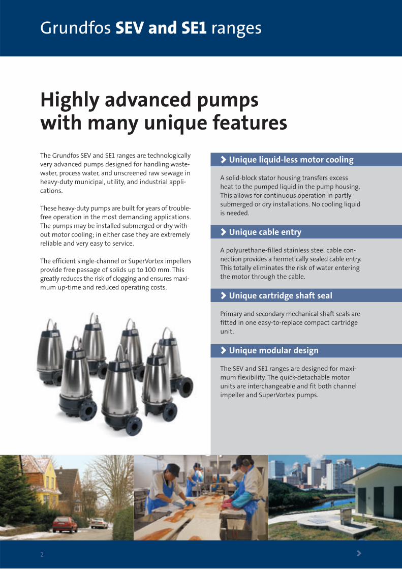
Highly advanced pumps with many unique featuresThe Grundfos SEV and SE1 ranges are technologicallyvery advanced pumps designed for handling waste-water, process water, and unscreened raw sewage inheavy-duty municipal, utility, and industrial appli-cations.
These heavy-duty pumps are built for years of trouble-free operation in the most demanding applications.The pumps may be installed submerged or dry with-out motor cooling; in either case they are extremelyreliable and very easy to service.
The efficient single-channel or SuperVortex impellersprovide free passage of solids up to 100 mm. Thisgreatly reduces the risk of clogging and ensures maxi-mum up-time and reduced operating costs.
> Unique liquid-less motor cooling
A solid-block stator housing transfers excessheat to the pumped liquid in the pump housing.This allows for continuous operation in partlysubmerged or dry installations. No cooling liquidis needed.
> Unique cable entry
A polyurethane-filled stainless steel cable con-nection provides a hermetically sealed cable entry.This totally eliminates the risk of water enteringthe motor through the cable.
> Unique cartridge shaft seal
Primary and secondary mechanical shaft seals arefitted in one easy-to-replace compact cartridgeunit.
> Unique modular design
The SEV and SE1 ranges are designed for maxi-mum flexibility. The quick-detachable motorunits are interchangeable and fit both channelimpeller and SuperVortex pumps.
Installation
>3
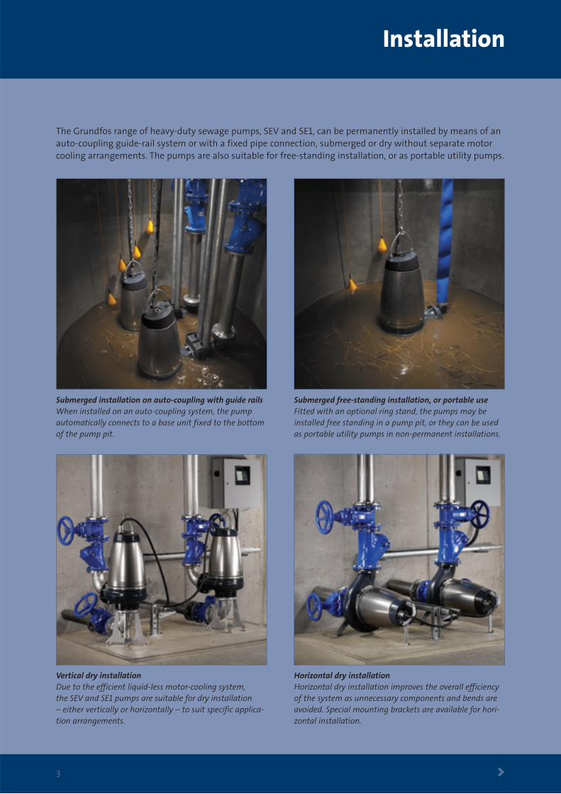
The Grundfos range of heavy-duty sewage pumps, SEV and SE1, can be permanently installed by means of anauto-coupling guide-rail system or with a fixed pipe connection, submerged or dry without separate motorcooling arrangements. The pumps are also suitable for free-standing installation, or as portable utility pumps.
Submerged free-standing installation, or portable useFitted with an optional ring stand, the pumps may beinstalled free standing in a pump pit, or they can be usedas portable utility pumps in non-permanent installations.
Vertical dry installation Due to the efficient liquid-less motor-cooling system, the SEV and SE1 pumps are suitable for dry installation – either vertically or horizontally – to suit specific applica-tion arrangements.
Horizontal dry installation Horizontal dry installation improves the overall efficiencyof the system as unnecessary components and bends areavoided. Special mounting brackets are available for hori-zontal installation.
Submerged installation on auto-coupling with guide railsWhen installed on an auto-coupling system, the pumpautomatically connects to a base unit fixed to the bottomof the pump pit.
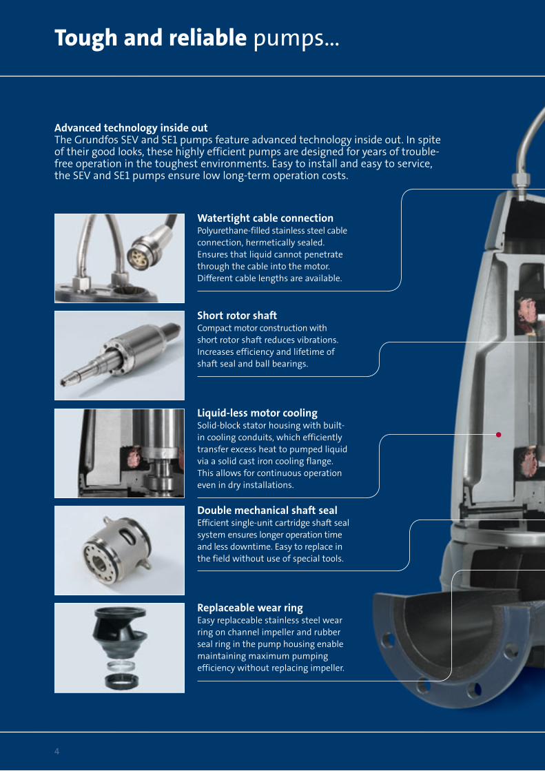
Advanced technology inside outThe Grundfos SEV and SE1 pumps feature advanced technology inside out. In spiteof their good looks, these highly efficient pumps are designed for years of trouble-free operation in the toughest environments. Easy to install and easy to service,the SEV and SE1 pumps ensure low long-term operation costs.
Short rotor shaftCompact motor construction with short rotor shaft reduces vibrations.Increases efficiency and lifetime ofshaft seal and ball bearings.
Watertight cable connectionPolyurethane-filled stainless steel cableconnection, hermetically sealed.Ensures that liquid cannot penetratethrough the cable into the motor.Different cable lengths are available.
Liquid-less motor coolingSolid-block stator housing with built-in cooling conduits, which efficientlytransfer excess heat to pumped liquidvia a solid cast iron cooling flange.This allows for continuous operationeven in dry installations.
Double mechanical shaft sealEfficient single-unit cartridge shaft sealsystem ensures longer operation timeand less downtime. Easy to replace inthe field without use of special tools.
Replaceable wear ringEasy replaceable stainless steel wearring on channel impeller and rubberseal ring in the pump housing enablemaintaining maximum pumpingefficiency without replacing impeller.
Tough and reliable pumps…
4
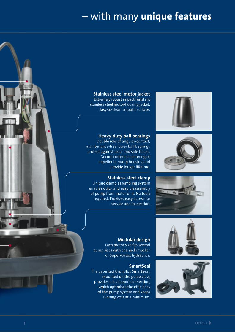
Stainless steel motor jacketExtremely robust impact-resistant
stainless steel motor-housing jacket.Easy-to-clean smooth surface.
Heavy-duty ball bearingsDouble row of angular-contact,
maintenance-free lower ball bearingsprotect against axial and side forces.
Secure correct positioning of impeller in pump housing and
provide longer lifetime.
Stainless steel clampUnique clamp assembling system
enables quick and easy disassemblyof pump from motor unit. No tools
required. Provides easy access forservice and inspection.
– with many unique features
Details >5
Modular designEach motor size fits several
pump sizes with channel-impelleror SuperVortex hydraulics.
SmartSealThe patented Grundfos SmartSeal,
mounted on the guide claw,provides a leak-proof connection,
which optimises the efficiency of the pump system and keeps
running cost at a minimum.
Grundfos SuperVortex-impeller pumps
SuperVortex impeller >6
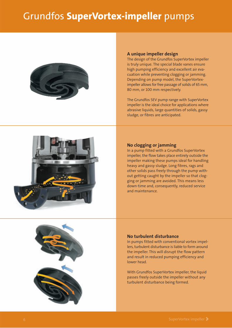
A unique impeller designThe design of the Grundfos SuperVortex impelleris truly unique. The special blade vanes ensurehigh pumping efficiency and excellent air eva-cuation while preventing clogging or jamming.Depending on pump model, the SuperVortex-impeller allows for free passage of solids of 65 mm,80 mm, or 100 mm respectively.
The Grundfos SEV pump range with SuperVorteximpeller is the ideal choice for applications whereabrasive liquids, large quantities of solids, gassysludge, or fibres are anticipated.
No clogging or jammingIn a pump fitted with a Grundfos SuperVorteximpeller, the flow takes place entirely outside theimpeller making these pumps ideal for handlingheavy and gassy sludge. Long fibres, rags andother solids pass freely through the pump with-out getting caught by the impeller so that clog-ging or jamming are avoided. This means lessdown-time and, consequently, reduced serviceand maintenance.
No turbulent disturbanceIn pumps fitted with conventional vortex impel-lers, turbulent disturbance is liable to form aroundthe impeller. This will disrupt the flow patternand result in reduced pumping efficiency andlower head.
With Grundfos SuperVortex impeller, the liquidpasses freely outside the impeller without anyturbulent disturbance being formed.
Grundfos channel-impeller pumps
Channel impellers >7
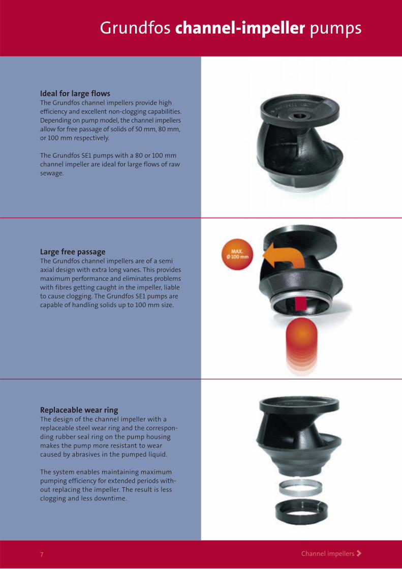
Ideal for large flowsThe Grundfos channel impellers provide highefficiency and excellent non-clogging capabilities.Depending on pump model, the channel impellersallow for free passage of solids of 50 mm, 80 mm,or 100 mm respectively.
The Grundfos SE1 pumps with a 80 or 100 mmchannel impeller are ideal for large flows of rawsewage.
Replaceable wear ringThe design of the channel impeller with areplaceable steel wear ring and the correspon-ding rubber seal ring on the pump housingmakes the pump more resistant to wearcaused by abrasives in the pumped liquid.
The system enables maintaining maximumpumping efficiency for extended periods with-out replacing the impeller. The result is lessclogging and less downtime.
Large free passage The Grundfos channel impellers are of a semiaxial design with extra long vanes. This providesmaximum performance and eliminates problemswith fibres getting caught in the impeller, liableto cause clogging. The Grundfos SE1 pumps arecapable of handling solids up to 100 mm size.
Performance overview and type key
Technical data >8
5 10 15 20 30 40 502
3
4
5
6
8
10
15
20
30
40
20 40 60 80 100 200
SE1.50 SE1.80SEV.65
SEV.80
SEV.100
SE1.100
50 Hz
Q [l/s]
H[m]
Q [m3/h]
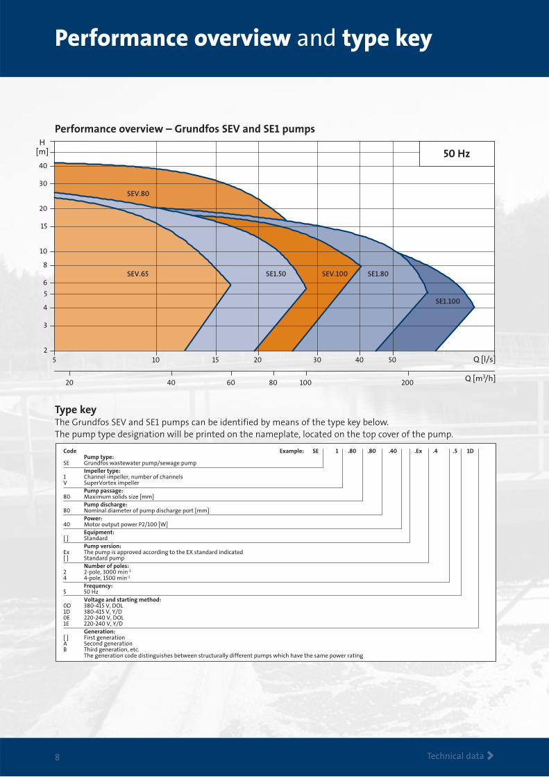
Code Example: SE 1 .80 .80 .40 .Ex .4 .5 1D Pump type:SE Grundfos wastewater pump/sewage pump Impeller type:1 Channel impeller, number of channelsV SuperVortex impeller Pump passage:80 Maximum solids size [mm] Pump discharge:80 Nominal diameter of pump discharge port [mm] Power:40 Motor output power P2/100 [W] Equipment:[ ] Standard Pump version:Ex The pump is approved according to the EX standard indicated[ ] Standard pump Number of poles:2 2-pole, 3000 min-1
4 4-pole, 1500 min-1
Frequency:5 50 Hz Voltage and starting method:0D 380-415 V, DOL1D 380-415 V, Y/D0E 220-240 V, DOL1E 220-240 V, Y/D Generation:[ ] First generationA Second generationB Third generation, etc. The generation code distinguishes between structurally different pumps which have the same power rating
Performance overview – Grundfos SEV and SE1 pumps
Type keyThe Grundfos SEV and SE1 pumps can be identified by means of the type key below. The pump type designation will be printed on the nameplate, located on the top cover of the pump.
0 4 8 12 16 20 24 28 32 36 Q [l/s]0
2
4
6
8
10
12
14
16
18
20
0 20 40 60 80 100 120 Q [m3/h]
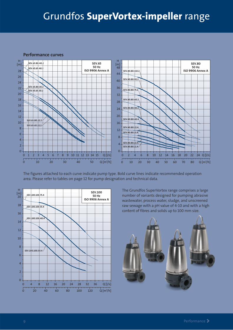
SEV.10050 Hz
ISO 9906 Annex A
H[m]
SEV.100.100.55.4
SEV.100.100.40.4
SEV.100.100.30.4
SEV.100.100.75.4
Grundfos SuperVortex-impeller range
Performance >9
Performance curves
The Grundfos SuperVortex range comprises a largenumber of variants designed for pumping abrasivewastewater, process water, sludge, and unscreenedraw sewage with a pH value of 4-10 and with a highcontent of fibres and solids up to 100 mm size.
0 1 2 3 4 5 6 7 8 9 10 11 12 13 14 15 Q [l/s]0
2
4
6
8
10
12
14
16
18
20
22
24
26
28
H[m]
0 10 20 30 40 50 Q [m3/h]
SEV.6550 Hz
ISO 9906 Annex A
SEV.65.80.40.2
SEV.65.65.40.2
SEV.65.80.30.2
SEV.65.65.30.2
SEV.65.65.22.2
SEV.65.80.22.2
0 2 4 6 8 10 12 14 16 18 20 22 24 Q [l/s]0
4
8
12
16
20
24
28
32
36
40
44
48
0 10 20 30 40 50 60 70 80 Q [m3/h]
SEV.8050 Hz
ISO 9906 Annex A
H[m]
SEV.80.80.110.2
SEV.80.80.92.2
SEV.80.80.75.2
SEV.80.80.60.2
SEV.80.80.40.2
SEV.80.80.40.4
SEV.80.80.22.4
SEV.80.80.15.4
SEV.80.80.13.4
SEV.80.80.11.4
The figures attached to each curve indicate pump type. Bold curve lines indicate recommended operationarea. Please refer to tables on page 12 for pump designation and technical data.
Grundfos single-channel-impeller range
Performance >10
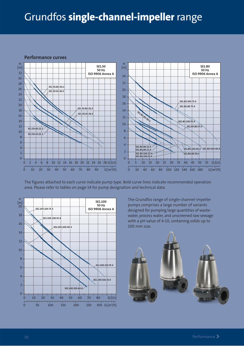
The Grundfos range of single-channel-impellerpumps comprises a large number of variantsdesigned for pumping large quantities of waste-water, process water, and unscreened raw sewagewith a pH value of 4-10, containing solids up to100 mm size.
0 5 10 15 20 25 30 35 40 45 50 550
2
4
6
8
10
12
14
16
18
20
22
24
0 20 40 60 80 100 120 140 160 180
Q [l/s]
H[m]
Q [m3/h]
SE1.8050 Hz
ISO 9906 Annex A
SE1.80.80.75.4
SE1.80.100.75.4
SE1.80.100.40.4SE1.80.100.30.4
SE1.80.80.30.4SE1.80.100.22.4SE1.80.100.15.4
SE1.80.80.15.4SE1.80.80.22.4
SE1.80.80.40.4 SE1.80.100.55.4
SE1.80.80.55.4
0 10 20 30 40 50 60 70 800
2
4
6
8
10
12
14
16
18
20
0 50 100 150 200 250 300
SE1.100.150.75.4
SE1.100.100.75.4
SE1.100.100.55.4
SE1.100.100.40.4
SE1.100.150.55.4
SE1.100.150.40.4
Q [l/s]
Q [m3/h]
H[m] SE1.100
50 HzISO 9906 Annex A
Performance curves
The figures attached to each curve indicate pump type. Bold curve lines indicate recommended operationarea. Please refer to tables on page 14 for pump designation and technical data.
0 2 4 6 8 10 12 14 16 18 20 22 24 26 280
2
4
6
8
10
12
14
16
18
20
22
24
26
28
30
32
0 10 20 30 40 50 60 70 80 90
Q [l/s]
H[m]
Q [m3/h]
SE1.50.80.40.2
SE1.50.65.40.2
SE1.50.80.30.2
SE1.50.65.30.2
SE1.50.80.22.2
SE1.50.65.22.2
SE1.5050 Hz
ISO 9906 Annex A
Technical data
Technical data >11
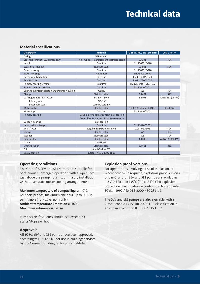
Material specifications
O-rings NBR rubber Seal ring for inlet (SE1 pumps only) NBR rubber (reinforcement stainless steel) 1.4301 304Impeller Cast iron EN-JL1030/GG20 Wear ring impeller Stainless steel 1.4301 304Pump housing Cast iron EN-JL1030/GG20 Stator housing Aluminum EN AB-AISI10mg Cover for oil chamber Cast iron EN-JL 1030/GG20 Bearing cover Cast iron EN-JL 1030/GG20 Primary bearing retainer Cast iron EN-GJS-450-10/GGG45 Support bearing retainer Cast iron EN-JL1040/GG25 Spring pin (intermediate flange/pump housing) Ø8x22 A2 304Clamp Stainless steel 1.4401 316Cartridge shaft seal system Stainless steel 1.4408 ASTM 351 (CF8M) Primary seal SiC/SiC Secondary seal Carbon/Ceramic Motor jacket Stainless steel 1.4301 (Optional 1.4401) 304 (316)Motor top Cast iron EN-JL1040/GG25 Primary bearing Double-row angular contact ball bearing from 3 kW 4-pole and 4 kW 2-pole motor Support bearing Ball bearing Intermediate flange Cast iron EN-JL1040/GG25 Shaft/rotor Regular iron/Stainless steel 1.0533/1.4301 304Screws Stainless steel A2 304Washer Stainless steel A2 304Cable entry Stainless steel 1.4408 ASTM 351 (CF8M)Cable H07RN-F Lifting bracket Stainless steel 1.4401 316Oil Shell Ondina 917 Epoxy coating Colour: NSC S 8005 R80B
Description Material DIN W.-Nr. / EN Standard AISI / ASTM
Explosion proof versionsFor applications involving a risk of explosion, orwhere otherwise required, explosion-proof versionsof the Grundfos SEV and SE1 pumps are available:II 2 GD, EEx d IIB 135°C (T4) c 135°C (T4) explosionprotection classification according to EN standards50 014-1997 / 50 018-2000 / 50 281-1-1.
The SEV and SE1 pumps are also available with aClass 1 Zone 2, Ex nA IIB 200°C (T3) classification inaccordance with the IEC 60079-15:1987.
Operating conditionsThe Grundfos SEV and SE1 pumps are suitable forcontinuous submerged operation with a liquid leveljust above the pump housing, or in a dry installationwithout separate motor cooling arrangements.
Maximum temperature of pumped liquid: 40°C. For short periods, maximum one hour, up to 60°C ispermissible (non-Ex versions only).Ambient temperature limitations: 40°CMaximum submersion: 20 m
Pump starts frequency should not exceed 20starts/stops per hour.
ApprovalsAll 50 Hz SEV and SE1 pumps have been approved,according to DIN 12050-1 for use in buildings servicesby the German Building Technology Institute.
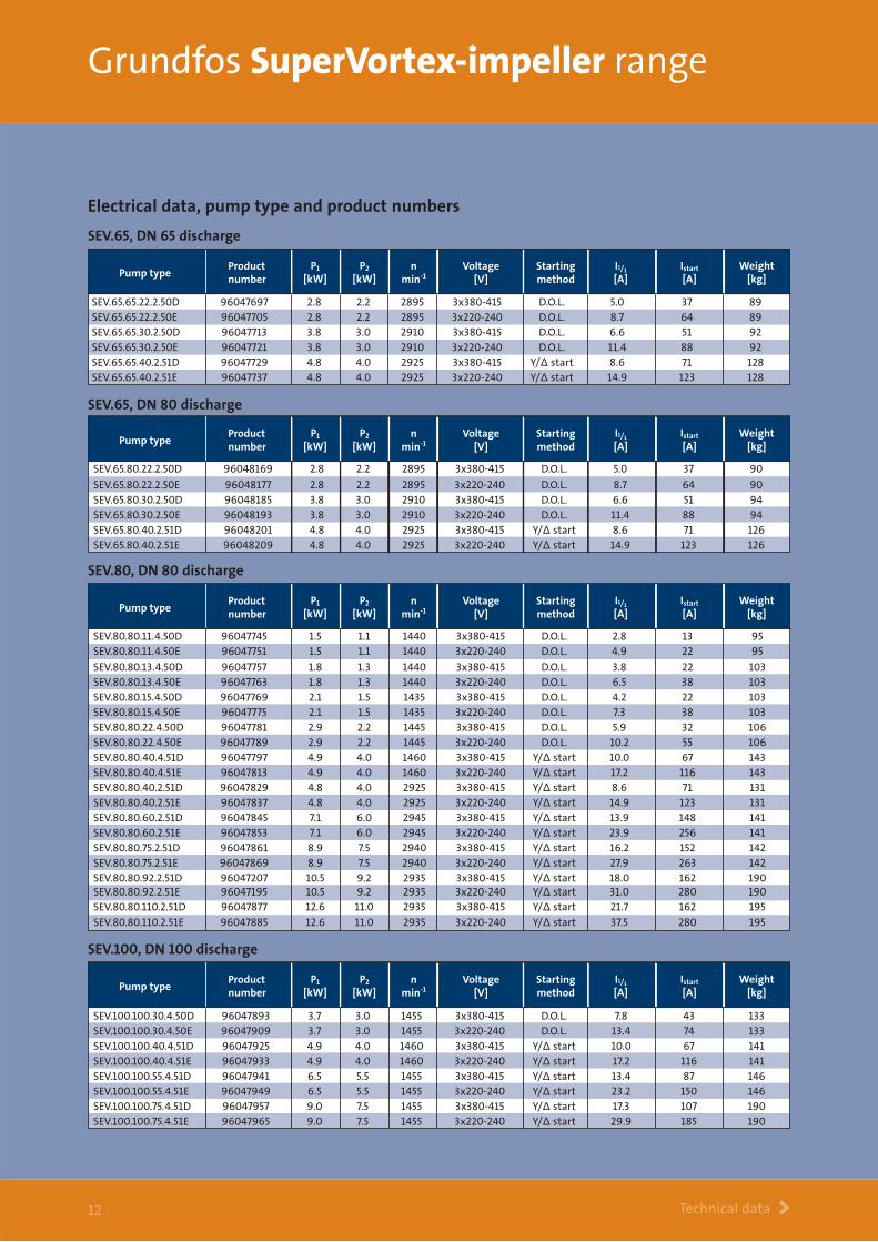
SEV.65, DN 65 discharge
SEV.65, DN 80 discharge
SEV.65.65.22.2.50D 96047697 2.8 2.2 2895 3x380-415 D.O.L. 5.0 37 89SEV.65.65.22.2.50E 96047705 2.8 2.2 2895 3x220-240 D.O.L. 8.7 64 89SEV.65.65.30.2.50D 96047713 3.8 3.0 2910 3x380-415 D.O.L. 6.6 51 92SEV.65.65.30.2.50E 96047721 3.8 3.0 2910 3x220-240 D.O.L. 11.4 88 92SEV.65.65.40.2.51D 96047729 4.8 4.0 2925 3x380-415 Y/∆ start 8.6 71 128SEV.65.65.40.2.51E 96047737 4.8 4.0 2925 3x220-240 Y/∆ start 14.9 123 128
Pump typeVoltage
[V]Starting method
nmin-1
Productnumber
Weight[kg]
P1
[kW]P2
[kW]I1/1
[A]Istart
[A]
SEV.65.80.22.2.50D 96048169 2.8 2.2 2895 3x380-415 D.O.L. 5.0 37 90
SEV.65.80.22.2.50E 96048177 2.8 2.2 2895 3x220-240 D.O.L. 8.7 64 90SEV.65.80.30.2.50D 96048185 3.8 3.0 2910 3x380-415 D.O.L. 6.6 51 94SEV.65.80.30.2.50E 96048193 3.8 3.0 2910 3x220-240 D.O.L. 11.4 88 94SEV.65.80.40.2.51D 96048201 4.8 4.0 2925 3x380-415 Y/∆ start 8.6 71 126SEV.65.80.40.2.51E 96048209 4.8 4.0 2925 3x220-240 Y/∆ start 14.9 123 126
Pump typeVoltage
[V]Starting method
nmin-1
Productnumber
Weight[kg]
P1
[kW]P2
[kW]I1/1
[A]Istart
[A]
Grundfos SuperVortex-impeller range
Technical data >12
SEV.80, DN 80 discharge
Pump typeVoltage
[V]Starting method
nmin-1
Productnumber
Weight[kg]
P1
[kW]P2
[kW]I1/1
[A]Istart
[A]
SEV.80.80.11.4.50D 96047745 1.5 1.1 1440 3x380-415 D.O.L. 2.8 13 95SEV.80.80.11.4.50E 96047751 1.5 1.1 1440 3x220-240 D.O.L. 4.9 22 95
SEV.80.80.13.4.50D 96047757 1.8 1.3 1440 3x380-415 D.O.L. 3.8 22 103SEV.80.80.13.4.50E 96047763 1.8 1.3 1440 3x220-240 D.O.L. 6.5 38 103SEV.80.80.15.4.50D 96047769 2.1 1.5 1435 3x380-415 D.O.L. 4.2 22 103SEV.80.80.15.4.50E 96047775 2.1 1.5 1435 3x220-240 D.O.L. 7.3 38 103SEV.80.80.22.4.50D 96047781 2.9 2.2 1445 3x380-415 D.O.L. 5.9 32 106SEV.80.80.22.4.50E 96047789 2.9 2.2 1445 3x220-240 D.O.L. 10.2 55 106SEV.80.80.40.4.51D 96047797 4.9 4.0 1460 3x380-415 Y/∆ start 10.0 67 143SEV.80.80.40.4.51E 96047813 4.9 4.0 1460 3x220-240 Y/∆ start 17.2 116 143SEV.80.80.40.2.51D 96047829 4.8 4.0 2925 3x380-415 Y/∆ start 8.6 71 131SEV.80.80.40.2.51E 96047837 4.8 4.0 2925 3x220-240 Y/∆ start 14.9 123 131SEV.80.80.60.2.51D 96047845 7.1 6.0 2945 3x380-415 Y/∆ start 13.9 148 141SEV.80.80.60.2.51E 96047853 7.1 6.0 2945 3x220-240 Y/∆ start 23.9 256 141SEV.80.80.75.2.51D 96047861 8.9 7.5 2940 3x380-415 Y/∆ start 16.2 152 142SEV.80.80.75.2.51E 96047869 8.9 7.5 2940 3x220-240 Y/∆ start 27.9 263 142SEV.80.80.92.2.51D 96047207 10.5 9.2 2935 3x380-415 Y/∆ start 18.0 162 190SEV.80.80.92.2.51E 96047195 10.5 9.2 2935 3x220-240 Y/∆ start 31.0 280 190SEV.80.80.110.2.51D 96047877 12.6 11.0 2935 3x380-415 Y/∆ start 21.7 162 195
SEV.80.80.110.2.51E 96047885 12.6 11.0 2935 3x220-240 Y/∆ start 37.5 280 195
SEV.100, DN 100 discharge
Pump typeVoltage
[V]Starting method
nmin-1
Productnumber
Weight[kg]
P1
[kW]P2
[kW]I1/1
[A]Istart
[A]
SEV.100.100.30.4.50D 96047893 3.7 3.0 1455 3x380-415 D.O.L. 7.8 43 133SEV.100.100.30.4.50E 96047909 3.7 3.0 1455 3x220-240 D.O.L. 13.4 74 133SEV.100.100.40.4.51D 96047925 4.9 4.0 1460 3x380-415 Y/∆ start 10.0 67 141SEV.100.100.40.4.51E 96047933 4.9 4.0 1460 3x220-240 Y/∆ start 17.2 116 141SEV.100.100.55.4.51D 96047941 6.5 5.5 1455 3x380-415 Y/∆ start 13.4 87 146SEV.100.100.55.4.51E 96047949 6.5 5.5 1455 3x220-240 Y/∆ start 23.2 150 146SEV.100.100.75.4.51D 96047957 9.0 7.5 1455 3x380-415 Y/∆ start 17.3 107 190SEV.100.100.75.4.51E 96047965 9.0 7.5 1455 3x220-240 Y/∆ start 29.9 185 190
Electrical data, pump type and product numbers
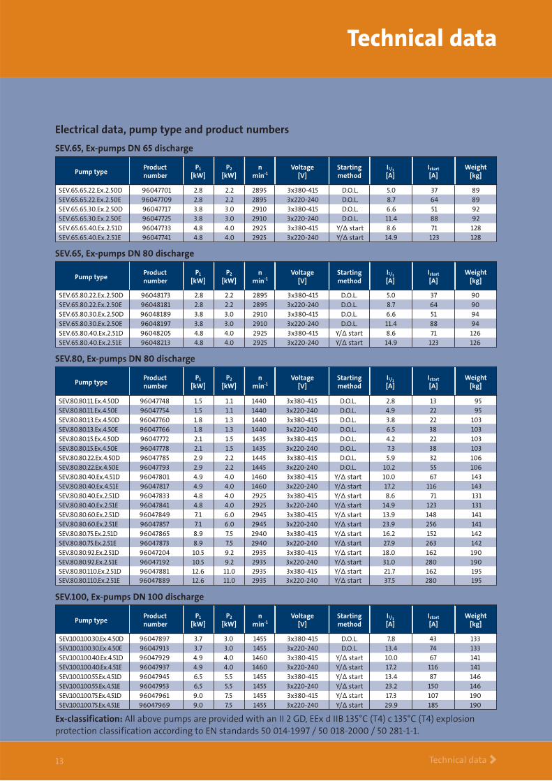
SEV.65, Ex-pumps DN 65 discharge
SEV.65.65.22.Ex.2.50D 96047701 2.8 2.2 2895 3x380-415 D.O.L. 5.0 37 89SEV.65.65.22.Ex.2.50E 96047709 2.8 2.2 2895 3x220-240 D.O.L. 8.7 64 89SEV.65.65.30.Ex.2.50D 96047717 3.8 3.0 2910 3x380-415 D.O.L. 6.6 51 92SEV.65.65.30.Ex.2.50E 96047725 3.8 3.0 2910 3x220-240 D.O.L. 11.4 88 92SEV.65.65.40.Ex.2.51D 96047733 4.8 4.0 2925 3x380-415 Y/∆ start 8.6 71 128SEV.65.65.40.Ex.2.51E 96047741 4.8 4.0 2925 3x220-240 Y/∆ start 14.9 123 128
Pump typeVoltage
[V]Starting method
nmin-1
Productnumber
Weight[kg]
P1
[kW]P2
[kW]I1/1
[A]Istart
[A]
SEV.65, Ex-pumps DN 80 discharge
SEV.65.80.22.Ex.2.50D 96048173 2.8 2.2 2895 3x380-415 D.O.L. 5.0 37 90SEV.65.80.22.Ex.2.50E 96048181 2.8 2.2 2895 3x220-240 D.O.L. 8.7 64 90SEV.65.80.30.Ex.2.50D 96048189 3.8 3.0 2910 3x380-415 D.O.L. 6.6 51 94SEV.65.80.30.Ex.2.50E 96048197 3.8 3.0 2910 3x220-240 D.O.L. 11.4 88 94SEV.65.80.40.Ex.2.51D 96048205 4.8 4.0 2925 3x380-415 Y/∆ start 8.6 71 126SEV.65.80.40.Ex.2.51E 96048213 4.8 4.0 2925 3x220-240 Y/∆ start 14.9 123 126
Pump typeVoltage
[V]Starting method
nmin-1
Productnumber
Weight[kg]
P1
[kW]P2
[kW]I1/1
[A]Istart
[A]
Technical data
Technical data >13
Ex-classification: All above pumps are provided with an II 2 GD, EEx d IIB 135°C (T4) c 135°C (T4) explosionprotection classification according to EN standards 50 014-1997 / 50 018-2000 / 50 281-1-1.
SEV.80, Ex-pumps DN 80 discharge
Pump typeVoltage
[V]Starting method
nmin-1
Productnumber
Weight[kg]
P1
[kW]P2
[kW]I1/1
[A]Istart
[A]
SEV.80.80.11.Ex.4.50D 96047748 1.5 1.1 1440 3x380-415 D.O.L. 2.8 13 95SEV.80.80.11.Ex.4.50E 96047754 1.5 1.1 1440 3x220-240 D.O.L. 4.9 22 95SEV.80.80.13.Ex.4.50D 96047760 1.8 1.3 1440 3x380-415 D.O.L. 3.8 22 103SEV.80.80.13.Ex.4.50E 96047766 1.8 1.3 1440 3x220-240 D.O.L. 6.5 38 103SEV.80.80.15.Ex.4.50D 96047772 2.1 1.5 1435 3x380-415 D.O.L. 4.2 22 103SEV.80.80.15.Ex.4.50E 96047778 2.1 1.5 1435 3x220-240 D.O.L. 7.3 38 103SEV.80.80.22.Ex.4.50D 96047785 2.9 2.2 1445 3x380-415 D.O.L. 5.9 32 106SEV.80.80.22.Ex.4.50E 96047793 2.9 2.2 1445 3x220-240 D.O.L. 10.2 55 106SEV.80.80.40.Ex.4.51D 96047801 4.9 4.0 1460 3x380-415 Y/∆ start 10.0 67 143SEV.80.80.40.Ex.4.51E 96047817 4.9 4.0 1460 3x220-240 Y/∆ start 17.2 116 143SEV.80.80.40.Ex.2.51D 96047833 4.8 4.0 2925 3x380-415 Y/∆ start 8.6 71 131SEV.80.80.40.Ex.2.51E 96047841 4.8 4.0 2925 3x220-240 Y/∆ start 14.9 123 131SEV.80.80.60.Ex.2.51D 96047849 7.1 6.0 2945 3x380-415 Y/∆ start 13.9 148 141SEV.80.80.60.Ex.2.51E 96047857 7.1 6.0 2945 3x220-240 Y/∆ start 23.9 256 141SEV.80.80.75.Ex.2.51D 96047865 8.9 7.5 2940 3x380-415 Y/∆ start 16.2 152 142SEV.80.80.75.Ex.2.51E 96047873 8.9 7.5 2940 3x220-240 Y/∆ start 27.9 263 142SEV.80.80.92.Ex.2.51D 96047204 10.5 9.2 2935 3x380-415 Y/∆ start 18.0 162 190SEV.80.80.92.Ex.2.51E 96047192 10.5 9.2 2935 3x220-240 Y/∆ start 31.0 280 190SEV.80.80.110.Ex.2.51D 96047881 12.6 11.0 2935 3x380-415 Y/∆ start 21.7 162 195SEV.80.80.110.Ex.2.51E 96047889 12.6 11.0 2935 3x220-240 Y/∆ start 37.5 280 195
SEV.100, Ex-pumps DN 100 discharge
SEV.100.100.30.Ex.4.50D 96047897 3.7 3.0 1455 3x380-415 D.O.L. 7.8 43 133SEV.100.100.30.Ex.4.50E 96047913 3.7 3.0 1455 3x220-240 D.O.L. 13.4 74 133SEV.100.100.40.Ex.4.51D 96047929 4.9 4.0 1460 3x380-415 Y/∆ start 10.0 67 141SEV.100.100.40.Ex.4.51E 96047937 4.9 4.0 1460 3x220-240 Y/∆ start 17.2 116 141SEV.100.100.55.Ex.4.51D 96047945 6.5 5.5 1455 3x380-415 Y/∆ start 13.4 87 146SEV.100.100.55.Ex.4.51E 96047953 6.5 5.5 1455 3x220-240 Y/∆ start 23.2 150 146SEV.100.100.75.Ex.4.51D 96047961 9.0 7.5 1455 3x380-415 Y/∆ start 17.3 107 190SEV.100.100.75.Ex.4.51E 96047969 9.0 7.5 1455 3x220-240 Y/∆ start 29.9 185 190
Pump typeVoltage
[V]Starting method
nmin-1
Productnumber
Weight[kg]
P1
[kW]P2
[kW]I1/1
[A]Istart
[A]
Electrical data, pump type and product numbers
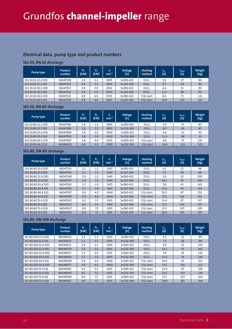
Grundfos channel-impeller range
Technical data >14
SE1.50, DN 65 discharge
SE1.50, DN 80 discharge
SE1.50.65.22.2.50D 96047509 2.8 2.2 2895 3x380-415 D.O.L. 5.0 37 86SE1.50.65.22.2.50E 96047513 2.8 2.2 2895 3x220-240 D.O.L. 8.7 64 86SE1.50.65.30.2.50D 96047517 3.8 3.0 2910 3x380-415 D.O.L. 6.6 51 90SE1.50.65.30.2.50E 96047521 3.8 3.0 2910 3x220-240 D.O.L. 11.4 88 90SE1.50.65.40.2.51D 96047525 4.8 4.0 2925 3x380-415 Y/∆ start 8.6 71 122SE1.50.65.40.2.51E 96047529 4.8 4.0 2925 3x220-240 Y/∆ start 14.9 123 122
Pump typeVoltage
[V]Starting method
nmin-1
Productnumber
Weight[kg]
P1
[kW]P2
[kW]I1/1
[A]Istart
[A]
SE1.50.80.22.2.50D 96047981 2.8 2.2 2895 3x380-415 D.O.L. 5.0 37 87SE1.50.80.22.2.50E 96047985 2.8 2.2 2895 3x220-240 D.O.L. 8.7 64 87SE1.50.80.30.2.50D 96047989 3.8 3.0 2910 3x380-415 D.O.L. 6.6 51 91SE1.50.80.30.2.50E 96047993 3.8 3.0 2910 3x220-240 D.O.L. 11.4 88 91SE1.50.80.40.2.51D 96047997 4.8 4.0 2925 3x380-415 Y/∆ start 8.6 71 123SE1.50.80.40.2.51E 96048001 4.8 4.0 2925 3x220-240 Y/∆ start 14.9 123 123
Pump typeVoltage
[V]Starting method
nmin-1
Productnumber
Weight[kg]
P1
[kW]P2
[kW]I1/1
[A]Istart
[A]
SE1.80, DN 80 discharge
Pump typeVoltage
[V]Starting method
nmin-1
Productnumber
Weight[kg]
P1
[kW]P2
[kW]I1/1
[A]Istart
[A]
SE1.80.80.15.4.50D 96047533 2.1 1.5 1435 3x380-415 D.O.L. 4.2 22 98SE1.80.80.15.4.50E 96047541 2.1 1.5 1435 3x220-240 D.O.L. 7.3 38 98SE1.80.80.22.4.50D 96047549 2.9 2.2 1445 3x380-415 D.O.L. 5.9 32 100SE1.80.80.22.4.50E 96047557 2.9 2.2 1445 3x220-240 D.O.L. 10.2 55 100SE1.80.80.30.4.50D 96047565 3.7 3.0 1455 3x380-415 D.O.L. 7.8 43 143SE1.80.80.30.4.50E 96047581 3.7 3.0 1455 3x220-240 D.O.L. 13.4 74 143SE1.80.80.40.4.51D 96047597 4.9 4.0 1460 3x380-415 Y/∆ start 10.0 67 152SE1.80.80.40.4.51E 96047605 4.9 4.0 1460 3x220-240 Y/∆ start 17.2 116 152SE1.80.80.55.4.51D 96047613 6.5 5.5 1455 3x380-415 Y/∆ start 13.4 87 157SE1.80.80.55.4.51E 96047621 6.5 5.5 1455 3x220-240 Y/∆ start 23.2 150 157SE1.80.80.75.4.51D 96047627 9.0 7.5 1455 3x380-415 Y/∆ start 17.3 107 205SE1.80.80.75.4.51E 96047635 9.0 7.5 1455 3x220-240 Y/∆ start 29.9 185 205
SE1.80, DN 100 discharge
Pump typeVoltage
[V]Starting method
nmin-1
Productnumber
Weight[kg]
P1
[kW]P2
[kW]I1/1
[A]Istart
[A]
SE1.80.100.15.4.50D 96048005 2.1 1.5 1435 3x380-415 D.O.L. 4.2 22 99SE1.80.100.15.4.50E 96048013 2.1 1.5 1435 3x220-240 D.O.L. 7.3 38 99SE1.80.100.22.4.50D 96048021 2.9 2.2 1445 3x380-415 D.O.L. 5.9 32 101SE1.80.100.22.4.50E 96048029 2.9 2.2 1445 3x220-240 D.O.L. 10.2 55 101SE1.80.100.30.4.50D 96048037 3.7 3.0 1455 3x380-415 D.O.L. 7.8 43 143SE1.80.100.30.4.50E 96048061 3.7 3.0 1455 3x220-240 D.O.L. 13.4 74 143SE1.80.100.40.4.51E 96048069 4.9 4.0 1460 3x380-415 Y/∆ start 10.0 67 153SE1.80.100.40.4.51D 96048077 4.9 4.0 1460 3x220-240 Y/∆ start 17.2 116 153SE1.80.100.55.4.51E 96048085 6.5 5.5 1455 3x380-415 Y/∆ start 13.4 87 158SE1.80.100.55.4.51D 96048093 6.5 5.5 1455 3x220-240 Y/∆ start 23.2 150 158SE1.80.100.75.4.51E 96048099 9.0 7.5 1455 3x380-415 Y/∆ start 17.3 107 204SE1.80.100.75.4.51D 96048107 9.0 7.5 1455 3x220-240 Y/∆ start 29.9 185 204
Electrical data, pump type and product numbers
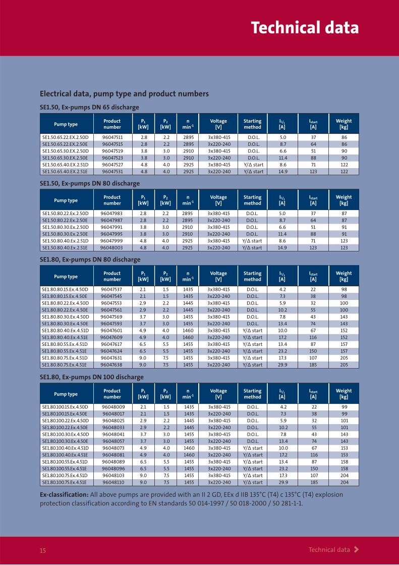
Technical data
Technical data >15
SE1.50, Ex-pumps DN 65 discharge
SE1.50.65.22.EX.2.50D 96047511 2.8 2.2 2895 3x380-415 D.O.L. 5.0 37 86SE1.50.65.22.EX.2.50E 96047515 2.8 2.2 2895 3x220-240 D.O.L. 8.7 64 86SE1.50.65.30.EX.2.50D 96047519 3.8 3.0 2910 3x380-415 D.O.L. 6.6 51 90SE1.50.65.30.EX.2.50E 96047523 3.8 3.0 2910 3x220-240 D.O.L. 11.4 88 90SE1.50.65.40.EX.2.51D 96047527 4.8 4.0 2925 3x380-415 Y/∆ start 8.6 71 122SE1.50.65.40.EX.2.51E 96047531 4.8 4.0 2925 3x220-240 Y/∆ start 14.9 123 122
Pump typeVoltage
[V]Starting method
nmin-1
Productnumber
Weight[kg]
P1
[kW]P2
[kW]I1/1
[A]Istart
[A]
SE1.50, Ex-pumps DN 80 discharge
SE1.50.80.22.Ex.2.50D 96047983 2.8 2.2 2895 3x380-415 D.O.L. 5.0 37 87SE1.50.80.22.Ex.2.50E 96047987 2.8 2.2 2895 3x220-240 D.O.L. 8.7 64 87SE1.50.80.30.Ex.2.50D 96047991 3.8 3.0 2910 3x380-415 D.O.L. 6.6 51 91SE1.50.80.30.Ex.2.50E 96047995 3.8 3.0 2910 3x220-240 D.O.L. 11.4 88 91SE1.50.80.40.Ex.2.51D 96047999 4.8 4.0 2925 3x380-415 Y/∆ start 8.6 71 123SE1.50.80.40.Ex.2.51E 96048003 4.8 4.0 2925 3x220-240 Y/∆ start 14.9 123 123
Pump typeVoltage
[V]Starting method
nmin-1
Productnumber
Weight[kg]
P1
[kW]P2
[kW]I1/1
[A]Istart
[A]
Ex-classification: All above pumps are provided with an II 2 GD, EEx d IIB 135°C (T4) c 135°C (T4) explosionprotection classification according to EN standards 50 014-1997 / 50 018-2000 / 50 281-1-1.
SE1.80, Ex-pumps DN 80 discharge
Pump typeVoltage
[V]Starting method
nmin-1
Productnumber
Weight[kg]
P1
[kW]P2
[kW]I1/1
[A]Istart
[A]
SE1.80.80.15.Ex.4.50D 96047537 2.1 1.5 1435 3x380-415 D.O.L. 4.2 22 98SE1.80.80.15.Ex.4.50E 96047545 2.1 1.5 1435 3x220-240 D.O.L. 7.3 38 98SE1.80.80.22.Ex.4.50D 96047553 2.9 2.2 1445 3x380-415 D.O.L. 5.9 32 100SE1.80.80.22.Ex.4.50E 96047561 2.9 2.2 1445 3x220-240 D.O.L. 10.2 55 100SE1.80.80.30.Ex.4.50D 96047569 3.7 3.0 1455 3x380-415 D.O.L. 7.8 43 143SE1.80.80.30.Ex.4.50E 96047593 3.7 3.0 1455 3x220-240 D.O.L. 13.4 74 143SE1.80.80.40.Ex.4.51D 96047601 4.9 4.0 1460 3x380-415 Y/∆ start 10.0 67 152SE1.80.80.40.Ex.4.51E 96047609 4.9 4.0 1460 3x220-240 Y/∆ start 17.2 116 152SE1.80.80.55.Ex.4.51D 96047617 6.5 5.5 1455 3x380-415 Y/∆ start 13.4 87 157SE1.80.80.55.Ex.4.51E 96047624 6.5 5.5 1455 3x220-240 Y/∆ start 23.2 150 157SE1.80.80.75.Ex.4.51D 96047631 9.0 7.5 1455 3x380-415 Y/∆ start 17.3 107 205SE1.80.80.75.Ex.4.51E 96047638 9.0 7.5 1455 3x220-240 Y/∆ start 29.9 185 205
SE1.80, Ex-pumps DN 100 discharge
Pump typeVoltage
[V]Starting method
nmin-1
Productnumber
Weight[kg]
P1
[kW]P2
[kW]I1/1
[A]Istart
[A]
SE1.80.100.15.Ex.4.50D 96048009 2.1 1.5 1435 3x380-415 D.O.L. 4.2 22 99SE1.80.100.15.Ex.4.50E 96048017 2.1 1.5 1435 3x220-240 D.O.L. 7.3 38 99SE1.80.100.22.Ex.4.50D 96048025 2.9 2.2 1445 3x380-415 D.O.L. 5.9 32 101SE1.80.100.22.Ex.4.50E 96048033 2.9 2.2 1445 3x220-240 D.O.L. 10.2 55 101SE1.80.100.30.Ex.4.50D 96048041 3.7 3.0 1455 3x380-415 D.O.L. 7.8 43 143SE1.80.100.30.Ex.4.50E 96048057 3.7 3.0 1455 3x220-240 D.O.L. 13.4 74 143SE1.80.100.40.Ex.4.51D 96048073 4.9 4.0 1460 3x380-415 Y/∆ start 10.0 67 153SE1.80.100.40.Ex.4.51E 96048081 4.9 4.0 1460 3x220-240 Y/∆ start 17.2 116 153SE1.80.100.55.Ex.4.51D 96048089 6.5 5.5 1455 3x380-415 Y/∆ start 13.4 87 158SE1.80.100.55.Ex.4.51E 96048096 6.5 5.5 1455 3x220-240 Y/∆ start 23.2 150 158SE1.80.100.75.Ex.4.51D 96048103 9.0 7.5 1455 3x380-415 Y/∆ start 17.3 107 204SE1.80.100.75.Ex.4.51E 96048110 9.0 7.5 1455 3x220-240 Y/∆ start 29.9 185 204
Electrical data, pump type and product numbers
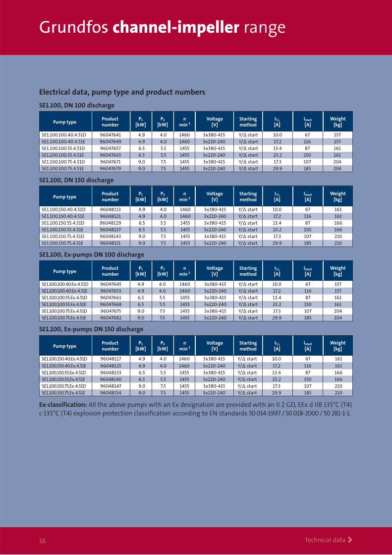
Grundfos channel-impeller range
Technical data >16
Ex-classification: All the above pumps with an Ex designation are provided with an II 2 GD, EEx d IIB 135°C (T4)c 135°C (T4) explosion protection classification according to EN standards 50 014-1997 / 50 018-2000 / 50 281-1-1.
SE1.100, DN 100 discharge
SE1.100, DN 150 discharge
Pump typeVoltage
[V]Starting method
nmin-1
Productnumber
Weight[kg]
P1
[kW]P2
[kW]I1/1
[A]Istart
[A]
SE1.100.150.40.4.51D 96048113 4.9 4.0 1460 3x380-415 Y/∆ start 10.0 67 161SE1.100.150.40.4.51E 96048121 4.9 4.0 1460 3x220-240 Y/∆ start 17.2 116 161SE1.100.150.55.4.51D 96048129 6.5 5.5 1455 3x380-415 Y/∆ start 13.4 87 166SE1.100.150.55.4.51E 96048137 6.5 5.5 1455 3x220-240 Y/∆ start 23.2 150 166SE1.100.150.75.4.51D 96048143 9.0 7.5 1455 3x380-415 Y/∆ start 17.3 107 210SE1.100.150.75.4.51E 96048151 9.0 7.5 1455 3x220-240 Y/∆ start 29.9 185 210
Pump typeVoltage
[V]Starting method
nmin-1
Productnumber
Weight[kg]
P1
[kW]P2
[kW]I1/1
[A]Istart
[A]
SE1.100.100.40.4.51D 96047641 4.9 4.0 1460 3x380-415 Y/∆ start 10.0 67 157SE1.100.100.40.4.51E 96047649 4.9 4.0 1460 3x220-240 Y/∆ start 17.2 116 157SE1.100.100.55.4.51D 96047657 6.5 5.5 1455 3x380-415 Y/∆ start 13.4 87 161SE1.100.100.55.4.51E 96047665 6.5 5.5 1455 3x220-240 Y/∆ start 23.2 150 161SE1.100.100.75.4.51D 96047671 9.0 7.5 1455 3x380-415 Y/∆ start 17.3 107 204SE1.100.100.75.4.51E 96047679 9.0 7.5 1455 3x220-240 Y/∆ start 29.9 185 204
SE1.100, Ex-pumps DN 100 discharge
SE1.100.100.40.Ex.4.51D 96047645 4.9 4.0 1460 3x380-415 Y/∆ start 10.0 67 157SE1.100.100.40.Ex.4.51E 96047653 4.9 4.0 1460 3x220-240 Y/∆ start 17.2 116 157SE1.100.100.55.Ex.4.51D 96047661 6.5 5.5 1455 3x380-415 Y/∆ start 13.4 87 161SE1.100.100.55.Ex.4.51E 96047668 6.5 5.5 1455 3x220-240 Y/∆ start 23.2 150 161SE1.100.100.75.Ex.4.51D 96047675 9.0 7.5 1455 3x380-415 Y/∆ start 17.3 107 204SE1.100.100.75.Ex.4.51E 96047682 9.0 7.5 1455 3x220-240 Y/∆ start 29.9 185 204
Pump typeVoltage
[V]Starting method
nmin-1
Productnumber
Weight[kg]
P1
[kW]P2
[kW]I1/1
[A]Istart
[A]
SE1.100, Ex-pumps DN 150 discharge
Pump typeVoltage
[V]Starting method
nmin-1
Productnumber
Weight[kg]
P1
[kW]P2
[kW]I1/1
[A]Istart
[A]
SE1.100.150.40.Ex.4.51D 96048117 4.9 4.0 1460 3x380-415 Y/∆ start 10.0 67 161
SE1.100.150.40.Ex.4.51E 96048125 4.9 4.0 1460 3x220-240 Y/∆ start 17.2 116 161SE1.100.150.55.Ex.4.51D 96048133 6.5 5.5 1455 3x380-415 Y/∆ start 13.4 87 166SE1.100.150.55.Ex.4.51E 96048140 6.5 5.5 1455 3x220-240 Y/∆ start 23.2 150 166SE1.100.150.75.Ex.4.51D 96048147 9.0 7.5 1455 3x380-415 Y/∆ start 17.3 107 210SE1.100.150.75.Ex.4.51E 96048154 9.0 7.5 1455 3x220-240 Y/∆ start 29.9 185 210
Electrical data, pump type and product numbers
Dimensions
Dimensions >17
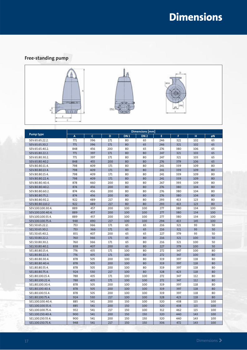
Free-standing pump
A C D DN 1 DN 2 E F H øNSEV.65.65.22.2. 771 396 171 80 65 246 321 102 65SEV.65.65.30.2 771 396 171 80 65 246 321 102 65SEV.65.65.40.2. 848 456 200 80 65 276 380 106 65SEV.65.80.22.2. 771 397 171 80 80 247 321 103 65SEV.65.80.30.2. 771 397 171 80 80 247 321 103 65SEV.65.80.40.2 848 455 200 80 80 276 379 106 65SEV.80.80.11.4. 798 409 171 80 80 241 339 109 80SEV.80.80.13.4. 798 409 171 80 80 241 339 109 80SEV.80.80.15.4. 798 409 171 80 80 241 339 109 80SEV.80.80.22.4. 798 409 171 80 80 241 339 109 80SEV.80.80.40.4. 878 460 200 80 80 267 393 109 80SEV.80.80.40.2. 874 456 200 80 80 276 380 104 80SEV.80.80.60.2. 874 456 200 80 80 276 380 104 80SEV.80.80.75.2. 874 456 200 80 80 276 380 104 80SEV.80.80.92.2. 922 489 217 80 80 293 413 123 80SEV.80.80.110.2 922 489 217 80 80 293 413 123 80SEV.100.100.30.4. 889 457 200 100 100 277 380 134 100SEV.100.100.40.4. 889 457 200 100 100 277 380 134 100SEV.100.100.55.4. 889 457 200 100 100 277 380 134 100SEV.100.100.75.4. 948 490 217 100 100 294 413 145 100
Pump type
SE1.50.65.22.2. 753 366 171 65 65 216 321 93 50SE1.50.65.30.2. 753 366 171 65 65 216 321 93 50SE1.50.65.40.2. 831 407 200 65 65 227 379 93 50SE1.50.80.22.2. 760 366 171 65 80 216 321 100 50SE1.50.80.30.2. 760 366 171 65 80 216 321 100 50SE1.50.80.40.2. 838 407 200 65 80 227 379 100 50SE1.80.80.15.4. 776 435 171 100 80 272 347 100 80SE1.80.80.22.4. 776 435 171 100 80 272 347 100 80SE1.80.80.30.4. 878 505 200 100 80 319 397 118 80SE1.80.80.40.4. 878 505 200 100 80 319 397 118 80SE1.80.80.55.4. 878 505 200 100 80 319 397 118 80SE1.80.80.75.4. 924 530 217 100 80 328 423 118 80SE1.80.100.15.4. 788 435 171 100 100 272 347 112 80SE1.80.100.22.4. 788 435 171 100 100 272 347 112 80SE1.80.100.30.4. 878 505 200 100 100 319 397 118 80SE1.80.100.40.4. 878 505 200 100 100 319 397 118 80SE1.80.100.55.4. 878 505 200 100 100 319 397 118 80SE1.80.100.75.4. 924 530 217 100 100 328 423 118 80SE1.100.100.40.4. 885 541 200 150 100 320 438 115 100SE1.100.100.55.4. 885 541 200 150 100 320 438 115 100SE1.100.100.75.4. 932 541 217 150 100 312 462 115 100SE1.100.150.40.4. 900 541 200 150 150 320 440 143 100SE1.100.150.55.4. 900 541 200 150 150 320 440 143 100SE1.100.150.75.4. 948 541 217 150 150 306 472 143 100
Dimensions [mm]
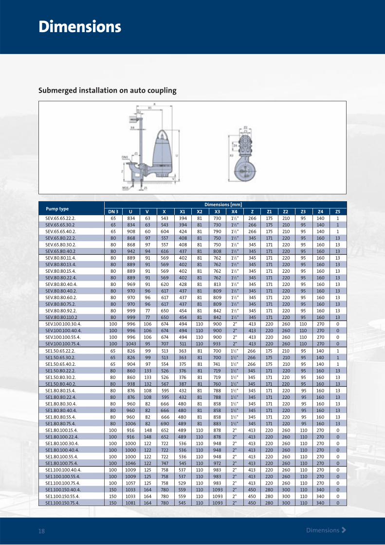
Submerged installation on auto coupling
DN 3 U V X X1 X2 X3 X4 Z Z1 Z2 Z3 Z4 Z5SEV.65.65.22.2. 65 834 63 543 394 81 730 11/2 " 266 175 210 95 140 1SEV.65.65.30.2 65 834 63 543 394 81 730 11/2 " 266 175 210 95 140 1SEV.65.65.40.2. 65 908 60 604 424 81 790 11/2 " 266 175 210 95 140 1SEV.65.80.22.2. 80 868 97 557 408 81 750 11/2 " 345 171 220 95 160 13SEV.65.80.30.2. 80 868 97 557 408 81 750 11/2 " 345 171 220 95 160 13SEV.65.80.40.2 80 942 94 616 437 81 808 11/2 " 345 171 220 95 160 13SEV.80.80.11.4. 80 889 91 569 402 81 762 11/2 " 345 171 220 95 160 13SEV.80.80.13.4. 80 889 91 569 402 81 762 11/2 " 345 171 220 95 160 13SEV.80.80.15.4. 80 889 91 569 402 81 762 11/2 " 345 171 220 95 160 13SEV.80.80.22.4. 80 889 91 569 402 81 762 11/2 " 345 171 220 95 160 13SEV.80.80.40.4. 80 969 91 620 428 81 813 11/2 " 345 171 220 95 160 13SEV.80.80.40.2. 80 970 96 617 437 81 809 11/2 " 345 171 220 95 160 13SEV.80.80.60.2. 80 970 96 617 437 81 809 11/2 " 345 171 220 95 160 13SEV.80.80.75.2. 80 970 96 617 437 81 809 11/2 " 345 171 220 95 160 13SEV.80.80.92.2. 80 999 77 650 454 81 842 11/2 " 345 171 220 95 160 13SEV.80.80.110.2 80 999 77 650 454 81 842 11/2 " 345 171 220 95 160 13SEV.100.100.30.4. 100 996 106 674 494 110 900 2" 413 220 260 110 270 0SEV.100.100.40.4. 100 996 106 674 494 110 900 2" 413 220 260 110 270 0SEV.100.100.55.4. 100 996 106 674 494 110 900 2" 413 220 260 110 270 0SEV.100.100.75.4. 100 1043 95 707 511 110 933 2" 413 220 260 110 270 0
SE1.50.65.22.2. 65 826 99 513 363 81 700 11/2 " 266 175 210 95 140 1SE1.50.65.30.2. 65 826 99 513 363 81 700 11/2 " 266 175 210 95 140 1SE1.50.65.40.2. 65 904 97 554 375 81 741 11/2 " 266 175 210 95 140 1SE1.50.80.22.2. 80 860 133 526 376 81 719 11/2 " 345 171 220 95 160 13SE1.50.80.30.2. 80 860 133 526 376 81 719 11/2 " 345 171 220 95 160 13SE1.50.80.40.2. 80 938 132 567 387 81 760 11/2 " 345 171 220 95 160 13
Dimensions [mm]Pump type
SE1.80.80.15.4. 80 876 108 595 432 81 788 11/2 " 345 171 220 95 160 13SE1.80.80.22.4. 80 876 108 595 432 81 788 11/2 " 345 171 220 95 160 13SE1.80.80.30.4. 80 960 82 666 480 81 858 11/2 " 345 171 220 95 160 13SE1.80.80.40.4. 80 960 82 666 480 81 858 11/2 " 345 171 220 95 160 13SE1.80.80.55.4. 80 960 82 666 480 81 858 11/2 " 345 171 220 95 160 13SE1.80.80.75.4. 80 1006 82 690 489 81 883 11/2 " 345 171 220 95 160 13SE1.80.100.15.4. 100 916 148 652 489 110 878 2" 413 220 260 110 270 0SE1.80.100.22.4. 100 916 148 652 489 110 878 2" 413 220 260 110 270 0SE1.80.100.30.4. 100 1000 122 722 536 110 948 2" 413 220 260 110 270 0SE1.80.100.40.4. 100 1000 122 722 536 110 948 2" 413 220 260 110 270 0SE1.80.100.55.4. 100 1000 122 722 536 110 948 2" 413 220 260 110 270 0SE1.80.100.75.4. 100 1046 122 747 545 110 972 2" 413 220 260 110 270 0SE1.100.100.40.4. 100 1009 125 758 537 110 983 2" 413 220 260 110 270 0SE1.100.100.55.4. 100 1009 125 758 537 110 983 2" 413 220 260 110 270 0SE1.100.100.75.4. 100 1057 125 758 529 110 983 2" 413 220 260 110 270 0SE1.100.150.40.4. 150 1033 164 780 559 110 1093 2" 450 280 300 110 340 0SE1.100.150.55.4. 150 1033 164 780 559 110 1093 2" 450 280 300 110 340 0SE1.100.150.75.4. 150 1081 164 780 545 110 1093 2" 450 280 300 110 340 0
Dimensions
Dimensions >18
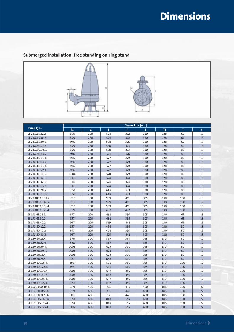
Submerged installation, free standing on ring stand
B1 G J P T T1 Y ø SEV.65.65.22.2. 899 280 524 372 330 128 65 18SEV.65.65.30.2 899 280 524 372 330 128 65 18SEV.65.65.40.2. 976 280 568 376 330 128 65 18SEV.65.80.22.2. 899 280 530 373 330 128 80 18SEV.65.80.30.2. 899 280 530 373 330 128 80 18SEV.65.80.40.2 976 280 573 376 330 128 80 18SEV.80.80.11.4. 926 280 527 379 330 128 80 18SEV.80.80.13.4. 926 280 527 379 330 128 80 18SEV.80.80.15.4. 926 280 527 379 330 128 80 18SEV.80.80.22.4. 926 280 527 379 330 128 80 18SEV.80.80.40.4. 1006 280 578 379 330 128 80 18SEV.80.80.40.2. 1002 280 574 374 330 128 80 18SEV.80.80.60.2. 1002 280 574 374 330 128 80 18SEV.80.80.75.2. 1002 280 574 374 330 128 80 18SEV.80.80.92.2. 1050 280 607 393 330 128 80 18SEV.80.80.110.2 1050 280 607 393 330 128 80 18SEV.100.100.30.4. 1019 300 599 411 355 130 100 19SEV.100.100.40.4. 1019 300 599 411 355 130 100 19SEV.100.100.55.4. 1019 300 599 411 355 130 100 19SEV.100.100.75.4. 1078 300 632 422 355 130 100 19
Pump type
SE1.50.65.22.2. 857 270 491 339 325 130 65 18SE1.50.65.30.2. 857 270 491 339 325 130 65 18SE1.50.65.40.2. 937 270 519 341 325 130 65 18SE1.50.80.22.2. 857 270 496 339 325 130 80 18SE1.50.80.30.2. 857 270 496 339 325 130 80 18SE1.50.80.40.2. 937 270 525 341 325 130 80 18SE1.80.80.15.4. 898 300 567 364 355 130 80 19SE1.80.80.22.4. 898 300 567 364 355 130 80 19SE1.80.80.30.4. 1008 300 623 390 355 130 80 19SE1.80.80.40.4. 1008 300 623 390 355 130 80 19SE1.80.80.55.4. 1008 300 623 390 355 130 80 19SE1.80.80.75.4. 1054 300 648 390 355 130 80 19SE1.80.100.15.4. 898 300 591 369 355 130 100 19SE1.80.100.22.4. 898 300 591 369 355 130 100 19SE1.80.100.30.4. 1008 300 647 395 355 130 100 19SE1.80.100.40.4. 1008 300 647 395 355 130 100 19SE1.80.100.55.4. 1008 300 647 395 355 130 100 19SE1.80.100.75.4. 1054 300 672 395 355 130 100 19SE1.100.100.40.4. 1071 400 711 445 450 186 100 22SE1.100.100.55.4. 1071 400 711 445 450 186 100 22SE1.100.100.75.4. 1118 400 706 445 450 186 100 22SE1.100.150.40.4. 1054 400 807 555 450 186 150 22SE1.100.150.55.4. 1054 400 807 555 450 186 150 22SE1.100.150.75.4. 1102 400 803 555 450 186 150 22
Dimensions [mm]
Dimensions
Dimensions >19
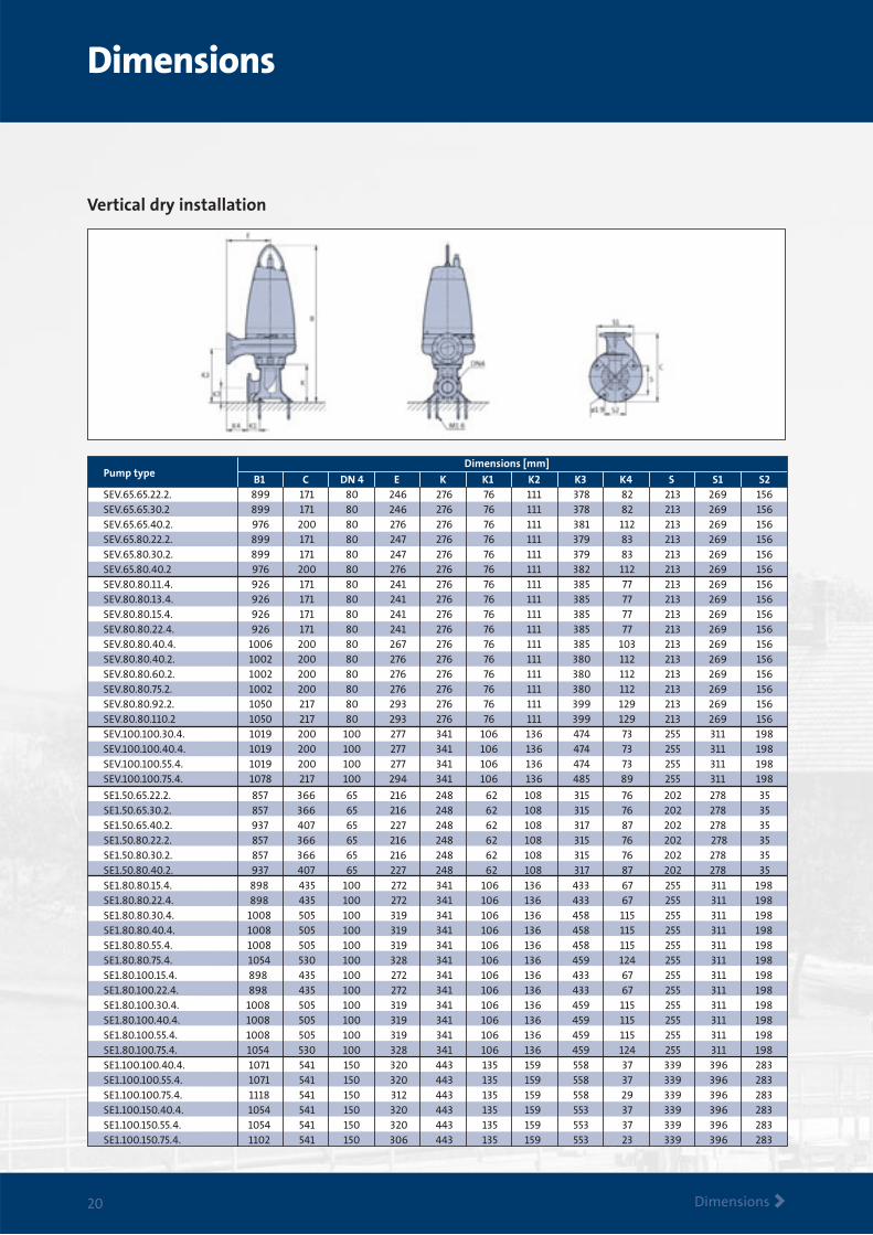
Vertical dry installation
SE1.50.65.22.2. 857 366 65 216 248 62 108 315 76 202 278 35SE1.50.65.30.2. 857 366 65 216 248 62 108 315 76 202 278 35SE1.50.65.40.2. 937 407 65 227 248 62 108 317 87 202 278 35SE1.50.80.22.2. 857 366 65 216 248 62 108 315 76 202 278 35SE1.50.80.30.2. 857 366 65 216 248 62 108 315 76 202 278 35SE1.50.80.40.2. 937 407 65 227 248 62 108 317 87 202 278 35
B1 C DN 4 E K K1 K2 K3 K4 S S1 S2SEV.65.65.22.2. 899 171 80 246 276 76 111 378 82 213 269 156SEV.65.65.30.2 899 171 80 246 276 76 111 378 82 213 269 156SEV.65.65.40.2. 976 200 80 276 276 76 111 381 112 213 269 156SEV.65.80.22.2. 899 171 80 247 276 76 111 379 83 213 269 156SEV.65.80.30.2. 899 171 80 247 276 76 111 379 83 213 269 156SEV.65.80.40.2 976 200 80 276 276 76 111 382 112 213 269 156SEV.80.80.11.4. 926 171 80 241 276 76 111 385 77 213 269 156SEV.80.80.13.4. 926 171 80 241 276 76 111 385 77 213 269 156SEV.80.80.15.4. 926 171 80 241 276 76 111 385 77 213 269 156SEV.80.80.22.4. 926 171 80 241 276 76 111 385 77 213 269 156SEV.80.80.40.4. 1006 200 80 267 276 76 111 385 103 213 269 156SEV.80.80.40.2. 1002 200 80 276 276 76 111 380 112 213 269 156SEV.80.80.60.2. 1002 200 80 276 276 76 111 380 112 213 269 156SEV.80.80.75.2. 1002 200 80 276 276 76 111 380 112 213 269 156SEV.80.80.92.2. 1050 217 80 293 276 76 111 399 129 213 269 156SEV.80.80.110.2 1050 217 80 293 276 76 111 399 129 213 269 156SEV.100.100.30.4. 1019 200 100 277 341 106 136 474 73 255 311 198SEV.100.100.40.4. 1019 200 100 277 341 106 136 474 73 255 311 198SEV.100.100.55.4. 1019 200 100 277 341 106 136 474 73 255 311 198SEV.100.100.75.4. 1078 217 100 294 341 106 136 485 89 255 311 198
SE1.80.80.15.4. 898 435 100 272 341 106 136 433 67 255 311 198SE1.80.80.22.4. 898 435 100 272 341 106 136 433 67 255 311 198SE1.80.80.30.4. 1008 505 100 319 341 106 136 458 115 255 311 198SE1.80.80.40.4. 1008 505 100 319 341 106 136 458 115 255 311 198SE1.80.80.55.4. 1008 505 100 319 341 106 136 458 115 255 311 198SE1.80.80.75.4. 1054 530 100 328 341 106 136 459 124 255 311 198SE1.80.100.15.4. 898 435 100 272 341 106 136 433 67 255 311 198SE1.80.100.22.4. 898 435 100 272 341 106 136 433 67 255 311 198SE1.80.100.30.4. 1008 505 100 319 341 106 136 459 115 255 311 198SE1.80.100.40.4. 1008 505 100 319 341 106 136 459 115 255 311 198SE1.80.100.55.4. 1008 505 100 319 341 106 136 459 115 255 311 198SE1.80.100.75.4. 1054 530 100 328 341 106 136 459 124 255 311 198SE1.100.100.40.4. 1071 541 150 320 443 135 159 558 37 339 396 283SE1.100.100.55.4. 1071 541 150 320 443 135 159 558 37 339 396 283SE1.100.100.75.4. 1118 541 150 312 443 135 159 558 29 339 396 283SE1.100.150.40.4. 1054 541 150 320 443 135 159 553 37 339 396 283SE1.100.150.55.4. 1054 541 150 320 443 135 159 553 37 339 396 283SE1.100.150.75.4. 1102 541 150 306 443 135 159 553 23 339 396 283
Dimensions [mm]Pump type
Dimensions
Dimensions >20
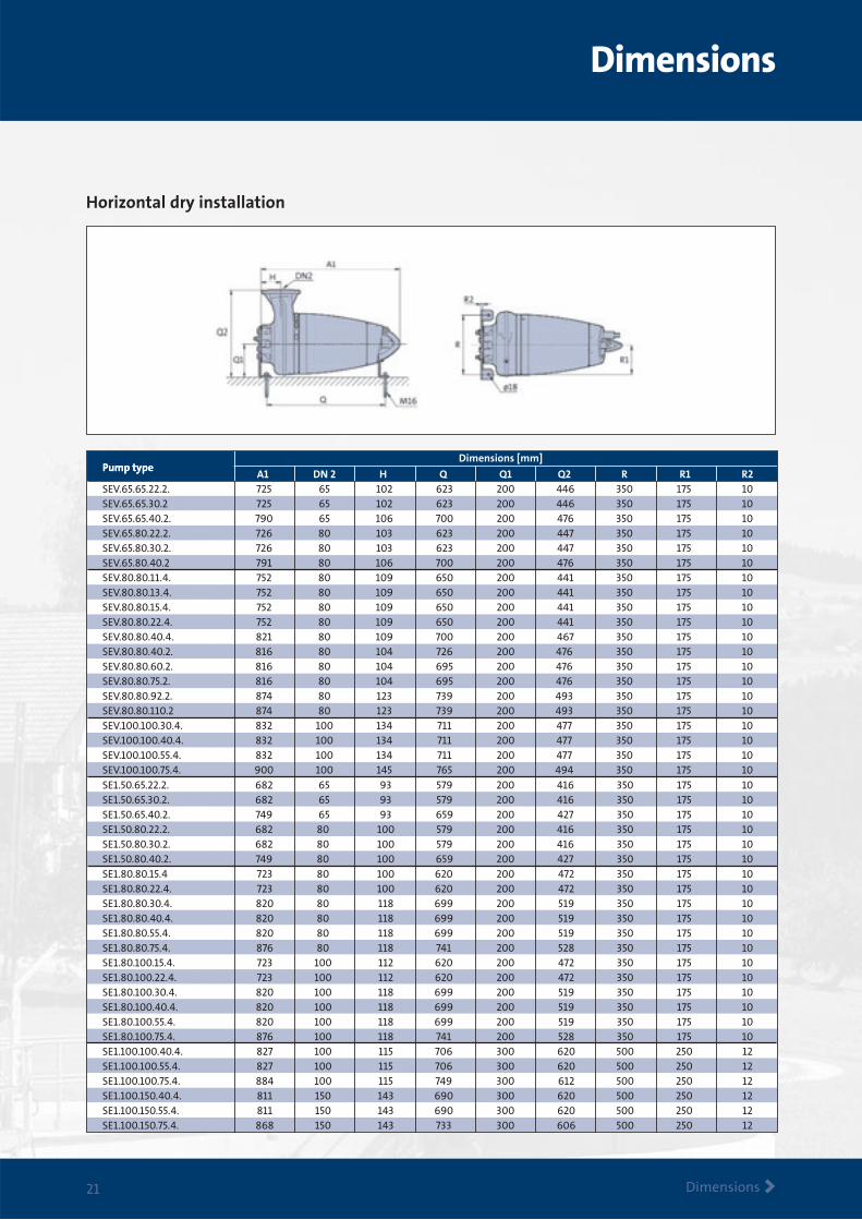
Horizontal dry installation
Pump typeDimensions [mm]
Pump type A1 DN 2 H Q Q1 Q2 R R1 R2SEV.65.65.22.2. 725 65 102 623 200 446 350 175 10SEV.65.65.30.2 725 65 102 623 200 446 350 175 10SEV.65.65.40.2. 790 65 106 700 200 476 350 175 10SEV.65.80.22.2. 726 80 103 623 200 447 350 175 10SEV.65.80.30.2. 726 80 103 623 200 447 350 175 10SEV.65.80.40.2 791 80 106 700 200 476 350 175 10SEV.80.80.11.4. 752 80 109 650 200 441 350 175 10SEV.80.80.13.4. 752 80 109 650 200 441 350 175 10SEV.80.80.15.4. 752 80 109 650 200 441 350 175 10SEV.80.80.22.4. 752 80 109 650 200 441 350 175 10SEV.80.80.40.4. 821 80 109 700 200 467 350 175 10SEV.80.80.40.2. 816 80 104 726 200 476 350 175 10SEV.80.80.60.2. 816 80 104 695 200 476 350 175 10SEV.80.80.75.2. 816 80 104 695 200 476 350 175 10SEV.80.80.92.2. 874 80 123 739 200 493 350 175 10SEV.80.80.110.2 874 80 123 739 200 493 350 175 10SEV.100.100.30.4. 832 100 134 711 200 477 350 175 10SEV.100.100.40.4. 832 100 134 711 200 477 350 175 10SEV.100.100.55.4. 832 100 134 711 200 477 350 175 10SEV.100.100.75.4. 900 100 145 765 200 494 350 175 10SE1.50.65.22.2. 682 65 93 579 200 416 350 175 10SE1.50.65.30.2. 682 65 93 579 200 416 350 175 10SE1.50.65.40.2. 749 65 93 659 200 427 350 175 10SE1.50.80.22.2. 682 80 100 579 200 416 350 175 10SE1.50.80.30.2. 682 80 100 579 200 416 350 175 10SE1.50.80.40.2. 749 80 100 659 200 427 350 175 10SE1.80.80.15.4 723 80 100 620 200 472 350 175 10SE1.80.80.22.4. 723 80 100 620 200 472 350 175 10SE1.80.80.30.4. 820 80 118 699 200 519 350 175 10SE1.80.80.40.4. 820 80 118 699 200 519 350 175 10SE1.80.80.55.4. 820 80 118 699 200 519 350 175 10SE1.80.80.75.4. 876 80 118 741 200 528 350 175 10SE1.80.100.15.4. 723 100 112 620 200 472 350 175 10SE1.80.100.22.4. 723 100 112 620 200 472 350 175 10SE1.80.100.30.4. 820 100 118 699 200 519 350 175 10SE1.80.100.40.4. 820 100 118 699 200 519 350 175 10SE1.80.100.55.4. 820 100 118 699 200 519 350 175 10SE1.80.100.75.4. 876 100 118 741 200 528 350 175 10SE1.100.100.40.4. 827 100 115 706 300 620 500 250 12SE1.100.100.55.4. 827 100 115 706 300 620 500 250 12SE1.100.100.75.4. 884 100 115 749 300 612 500 250 12SE1.100.150.40.4. 811 150 143 690 300 620 500 250 12SE1.100.150.55.4. 811 150 143 690 300 620 500 250 12SE1.100.150.75.4. 868 150 143 733 300 606 500 250 12
Dimensions
Dimensions >21
Accessories
Accessories>22
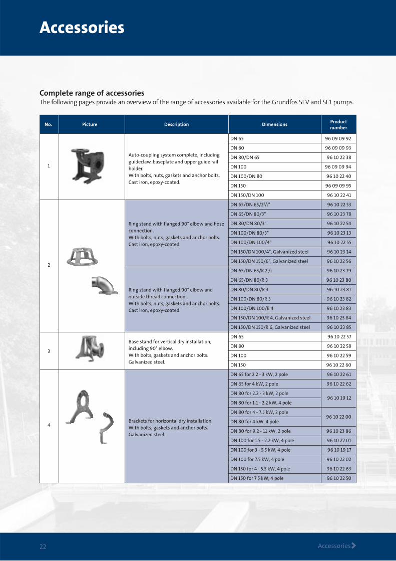
Complete range of accessoriesThe following pages provide an overview of the range of accessories available for the Grundfos SEV and SE1 pumps.
Description Dimensions Productnumber
PictureNo.
Auto-coupling system complete, including guideclaw, baseplate and upper guide rail holder. With bolts, nuts, gaskets and anchor bolts.Cast iron, epoxy-coated.
Ring stand with flanged 90° elbow and hoseconnection.With bolts, nuts, gaskets and anchor bolts.Cast iron, epoxy-coated.
Ring stand with flanged 90° elbow andoutside thread connection.With bolts, nuts, gaskets and anchor bolts.Cast iron, epoxy-coated.
Base stand for vertical dry installation, including 90° elbow.With bolts, gaskets and anchor bolts.Galvanized steel.
Brackets for horizontal dry installation.With bolts, gaskets and anchor bolts.Galvanized steel.
DN 65 96 09 09 92
DN 80 96 09 09 93
DN 80/DN 65 96 10 22 38
DN 100 96 09 09 94
DN 100/DN 80 96 10 22 40
DN 150 96 09 09 95
DN 150/DN 100 96 10 22 41
DN 65/DN 65/2 1/2" 96 10 22 53
DN 65/DN 80/3" 96 10 23 78
DN 80/DN 80/3" 96 10 22 54
DN 100/DN 80/3" 96 10 23 13
DN 100/DN 100/4" 96 10 22 55
DN 150/DN 100/4", Galvanized steel 96 10 23 14
DN 150/DN 150/6", Galvanized steel 96 10 22 56
DN 65/DN 65/R 21/2 96 10 23 79
DN 65/DN 80/R 3 96 10 23 80
DN 80/DN 80/R 3 96 10 23 81
DN 100/DN 80/R 3 96 10 23 82
DN 100/DN 100/R 4 96 10 23 83
DN 150/DN 100/R 4, Galvanized steel 96 10 23 84
DN 150/DN 150/R 6, Galvanized steel 96 10 23 85
DN 65 96 10 22 57
DN 80 96 10 22 58
DN 100 96 10 22 59
DN 150 96 10 22 60
DN 65 for 2.2 - 3 kW, 2 pole 96 10 22 61
DN 65 for 4 kW, 2 pole 96 10 22 62
DN 80 for 2.2 - 3 kW, 2 pole 96 10 19 12
DN 80 for 1.1 - 2.2 kW, 4 pole
DN 80 for 4 - 7.5 kW, 2 pole 96 10 22 00
DN 80 for 4 kW, 4 pole
DN 80 for 9.2 - 11 kW, 2 pole 96 10 23 86
DN 100 for 1.5 - 2.2 kW, 4 pole 96 10 22 01
DN 100 for 3 - 5.5 kW, 4 pole 96 10 19 17
DN 100 for 7.5 kW, 4 pole 96 10 22 02
DN 150 for 4 - 5.5 kW, 4 pole 96 10 22 63
DN 150 for 7.5 kW, 4 pole 96 10 22 50
1
2
3
4
Accessories
Accessories >23
Description Dimensions Productnumber
PictureNo.
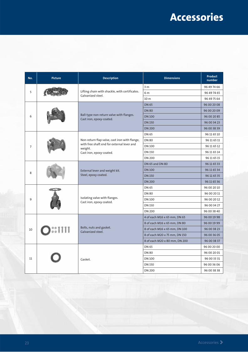
Lifting chain with shackle, with certificates.Galvanized steel.
Ball-type non-return valve with flanges.Cast iron, epoxy-coated.
Non-return flap valve, cast iron with flange,with free shaft end for external lever and weight.Cast iron, epoxy-coated.
External lever and weight kit.Steel, epoxy coated.
Isolating valve with flanges.Cast iron, epoxy coated.
Bolts, nuts and gasket.Galvanized steel.
Gasket.
3 m 96 49 74 66
6 m 96 49 74 65
10 m 96 49 75 64
DN 65 96 00 20 08
DN 80 96 00 20 09
DN 100 96 00 20 85
DN 150 96 00 34 23
DN 200 96 00 38 39
DN 65 96 11 65 10
DN 80 96 11 65 11
DN 100 96 11 65 12
DN 150 96 11 65 14
DN 200 96 11 65 15
DN 65 and DN 80 96 11 65 33
DN 100 96 11 65 34
DN 150 96 11 65 35
DN 200 96 11 65 36
DN 65 96 00 20 10
DN 80 96 00 20 11
DN 100 96 00 20 12
DN 150 96 00 34 27
DN 200 96 00 38 40
4 of each M16 x 65 mm, DN 65 96 00 19 98
8 of each M16 x 65 mm, DN 80 96 00 19 99
8 of each M16 x 65 mm, DN 100 96 00 38 23
8 of each M20 x 75 mm, DN 150 96 00 36 05
8 of each M20 x 80 mm, DN 200 96 00 38 37
DN 65 96 00 20 00
DN 80 96 00 20 01
DN 100 96 00 33 31
DN 150 96 00 36 06
DN 200 96 00 38 38
5
6
7
8
9
10
11
Accessories
Accessories >24
Description Dimensions Productnumber
PictureNo.
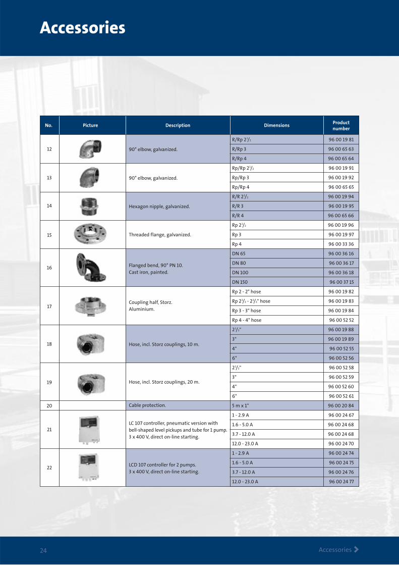
90° elbow, galvanized.
90° elbow, galvanized.
Hexagon nipple, galvanized.
Threaded flange, galvanized.
Flanged bend, 90° PN 10.Cast iron, painted.
Coupling half, Storz.Aluminium.
Hose, incl. Storz couplings, 10 m.
Hose, incl. Storz couplings, 20 m.
Cable protection.
LC 107 controller, pneumatic version with bell-shaped level pickups and tube for 1 pump.3 x 400 V, direct on-line starting.
LCD 107 controller for 2 pumps. 3 x 400 V, direct on-line starting.
R/Rp 2 1/2 96 00 19 81
R/Rp 3 96 00 65 63
R/Rp 4 96 00 65 64
Rp/Rp 2 1/2 96 00 19 91
Rp/Rp 3 96 00 19 92
Rp/Rp 4 96 00 65 65
R/R 2 1/2 96 00 19 94
R/R 3 96 00 19 95
R/R 4 96 00 65 66
Rp 2 1/2 96 00 19 96
Rp 3 96 00 19 97
Rp 4 96 00 33 36
DN 65 96 00 36 16
DN 80 96 00 36 17
DN 100 96 00 36 18
DN 150 96 00 37 15
Rp 2 - 2" hose 96 00 19 82
Rp 2 1/2 - 2 1/2" hose 96 00 19 83
Rp 3 - 3" hose 96 00 19 84
Rp 4 - 4" hose 96 00 52 52
2 1/2" 96 00 19 88
3" 96 00 19 89
4" 96 00 52 55
6" 96 00 52 56
2 1/2" 96 00 52 58
3" 96 00 52 59
4" 96 00 52 60
6" 96 00 52 61
5 m x 1" 96 00 20 84
1 - 2.9 A 96 00 24 67
1.6 - 5.0 A 96 00 24 68
3.7 - 12.0 A 96 00 24 68
12.0 - 23.0 A 96 00 24 70
1 - 2.9 A 96 00 24 74
1.6 - 5.0 A 96 00 24 75
3.7 - 12.0 A 96 00 24 76
12.0 - 23.0 A 96 00 24 77
12
13
14
15
16
17
18
19
20
21
22
Accessories
Accessories >25
Description Dimensions Productnumber
PictureNo.
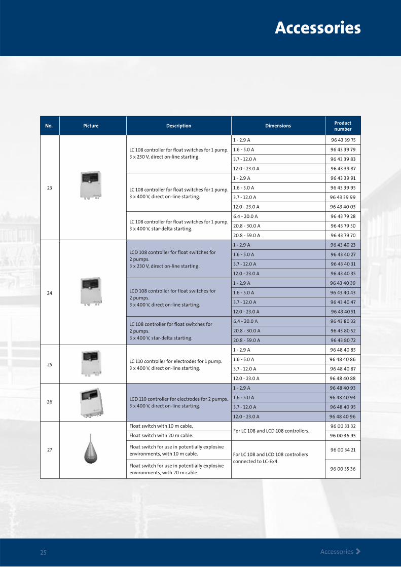
LC 108 controller for float switches for 1 pump. 3 x 230 V, direct on-line starting.
LC 108 controller for float switches for 1 pump. 3 x 400 V, direct on-line starting.
LC 108 controller for float switches for 1 pump. 3 x 400 V, star-delta starting.
LCD 108 controller for float switches for 2 pumps.3 x 230 V, direct on-line starting.
LCD 108 controller for float switches for 2 pumps. 3 x 400 V, direct on-line starting.
LC 108 controller for float switches for 2 pumps.3 x 400 V, star-delta starting.
LC 110 controller for electrodes for 1 pump. 3 x 400 V, direct on-line starting.
LCD 110 controller for electrodes for 2 pumps. 3 x 400 V, direct on-line starting.
Float switch with 10 m cable.
Float switch with 20 m cable.
Float switch for use in potentially explosive environments, with 10 m cable.
Float switch for use in potentially explosive environments, with 20 m cable.
1 - 2.9 A 96 43 39 75
1.6 - 5.0 A 96 43 39 79
3.7 - 12.0 A 96 43 39 83
12.0 - 23.0 A 96 43 39 87
1 - 2.9 A 96 43 39 91
1.6 - 5.0 A 96 43 39 95
3.7 - 12.0 A 96 43 39 99
12.0 - 23.0 A 96 43 40 03
6.4 - 20.0 A 96 43 79 28
20.8 - 30.0 A 96 43 79 50
20.8 - 59.0 A 96 43 79 70
1 - 2.9 A 96 43 40 23
1.6 - 5.0 A 96 43 40 27
3.7 - 12.0 A 96 43 40 31
12.0 - 23.0 A 96 43 40 35
1 - 2.9 A 96 43 40 39
1.6 - 5.0 A 96 43 40 43
3.7 - 12.0 A 96 43 40 47
12.0 - 23.0 A 96 43 40 51
6.4 - 20.0 A 96 43 80 32
20.8 - 30.0 A 96 43 80 52
20.8 - 59.0 A 96 43 80 72
1 - 2.9 A 96 48 40 85
1.6 - 5.0 A 96 48 40 86
3.7 - 12.0 A 96 48 40 87
12.0 - 23.0 A 96 48 40 88
1 - 2.9 A 96 48 40 93
1.6 - 5.0 A 96 48 40 94
3.7 - 12.0 A 96 48 40 95
12.0 - 23.0 A 96 48 40 96
For LC 108 and LCD 108 controllers. 96 00 33 32
96 00 36 95
96 00 34 21
96 00 35 36
For LC 108 and LCD 108 controllersconnected to LC-Ex4.
23
24
25
26
27
Description Dimensions Productnumber
PictureNo.
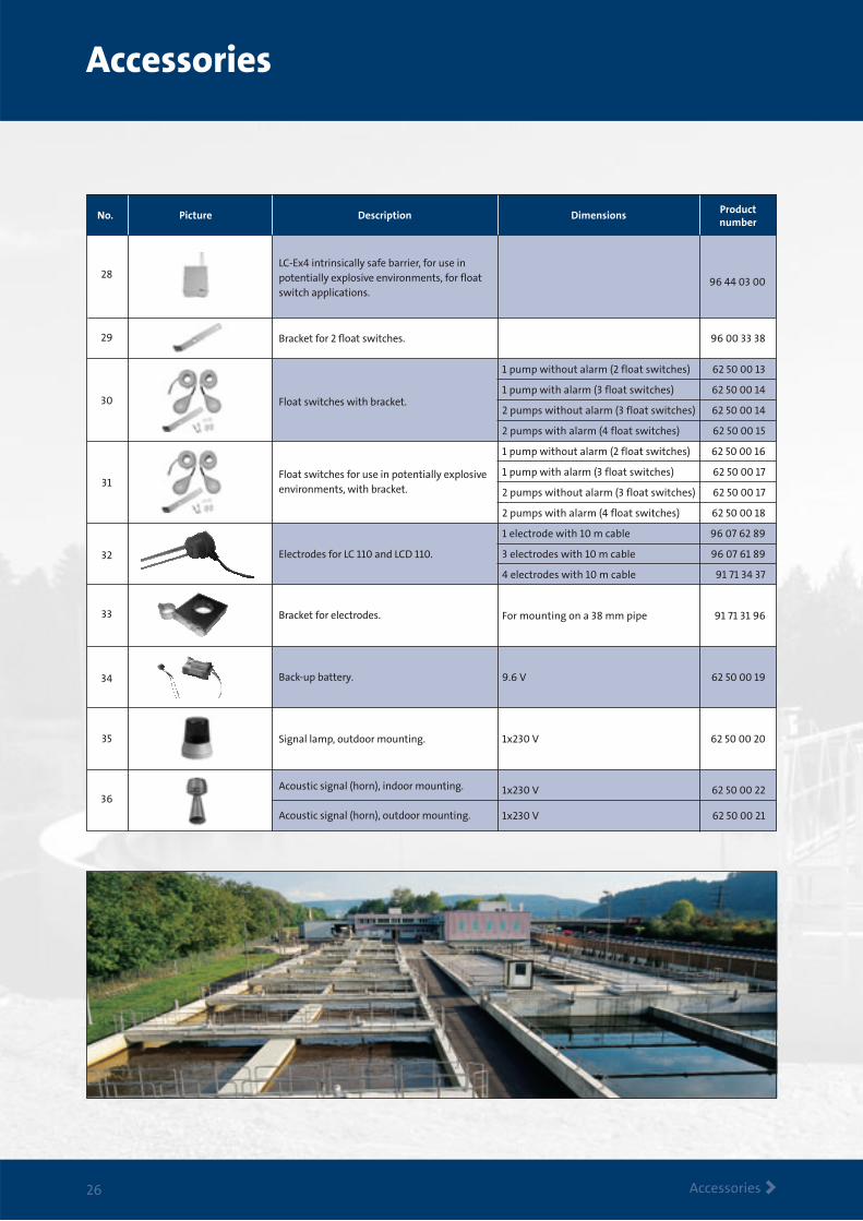
LC-Ex4 intrinsically safe barrier, for use in potentially explosive environments, for float switch applications.
Bracket for 2 float switches.
Float switches with bracket.
Float switches for use in potentially explosive environments, with bracket.
Electrodes for LC 110 and LCD 110.
Bracket for electrodes.
Back-up battery.
Signal lamp, outdoor mounting.
Acoustic signal (horn), indoor mounting.
Acoustic signal (horn), outdoor mounting.
96 44 03 00
96 00 33 38
1 pump without alarm (2 float switches) 62 50 00 13
1 pump with alarm (3 float switches) 62 50 00 14
2 pumps without alarm (3 float switches) 62 50 00 14
2 pumps with alarm (4 float switches) 62 50 00 15
1 pump without alarm (2 float switches) 62 50 00 16
1 pump with alarm (3 float switches) 62 50 00 17
2 pumps without alarm (3 float switches) 62 50 00 17
2 pumps with alarm (4 float switches) 62 50 00 18
1 electrode with 10 m cable 96 07 62 89
3 electrodes with 10 m cable 96 07 61 89
4 electrodes with 10 m cable 91 71 34 37
For mounting on a 38 mm pipe 91 71 31 96
9.6 V 62 50 00 19
1x230 V 62 50 00 20
1x230 V 62 50 00 22
1x230 V 62 50 00 21
28
30
29
31
32
33
34
35
36
Accessories
Accessories >26
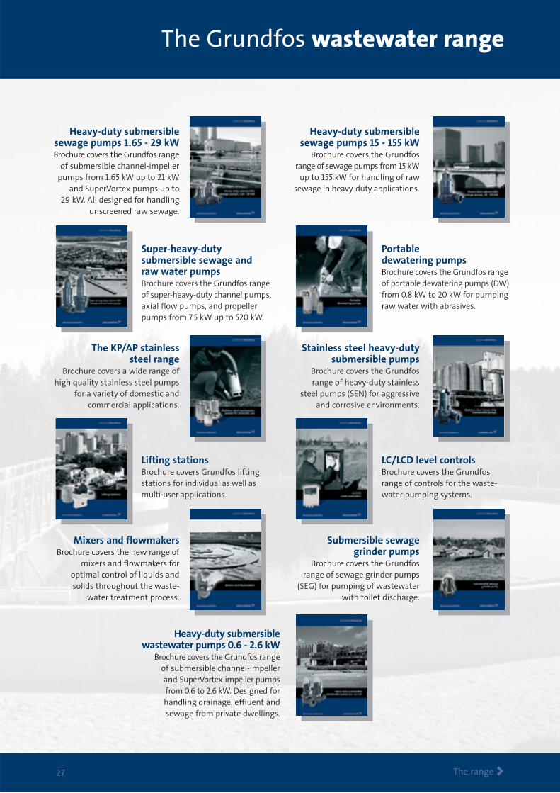
Heavy-duty submersiblesewage pumps 1.65 - 29 kWBrochure covers the Grundfos range
of submersible channel-impellerpumps from 1.65 kW up to 21 kW
and SuperVortex pumps up to 29 kW. All designed for handling
unscreened raw sewage.
Heavy-duty submersiblesewage pumps 15 - 155 kW
Brochure covers the Grundfosrange of sewage pumps from 15 kW
up to 155 kW for handling of rawsewage in heavy-duty applications.
Super-heavy-duty submersible sewage andraw water pumpsBrochure covers the Grundfos rangeof super-heavy-duty channel pumps,axial flow pumps, and propellerpumps from 7.5 kW up to 520 kW.
Portable dewatering pumpsBrochure covers the Grundfos rangeof portable dewatering pumps (DW)from 0.8 kW to 20 kW for pumpingraw water with abrasives.
The KP/AP stainless steel range
Brochure covers a wide range ofhigh quality stainless steel pumps
for a variety of domestic and commercial applications.
Stainless steel heavy-dutysubmersible pumps
Brochure covers the Grundfosrange of heavy-duty stainless
steel pumps (SEN) for aggressiveand corrosive environments.
Lifting stationsBrochure covers Grundfos lifting stations for individual as well as multi-user applications.
LC/LCD level controlsBrochure covers the Grundfosrange of controls for the waste-water pumping systems.
Mixers and flowmakersBrochure covers the new range of
mixers and flowmakers for optimal control of liquids andsolids throughout the waste-
water treatment process.
Submersible sewagegrinder pumps
Brochure covers the Grundfosrange of sewage grinder pumps
(SEG) for pumping of wastewaterwith toilet discharge.
Heavy-duty submersible wastewater pumps 0.6 - 2.6 kW
Brochure covers the Grundfos range of submersible channel-impeller and SuperVortex-impeller pumps from 0.6 to 2.6 kW. Designed forhandling drainage, effluent andsewage from private dwellings.
The Grundfos wastewater range
The range >27

www.grundfos.com
Business with an attitude
Knowledge The sharing of knowledge, experience
and expertise across our global network will always
lead our business forward.
Innovation Combining the best technology with
fresh ways of thinking, we will continue to develop
even better pumps, systems, services and standards.
Solution With a complete product range, capable
of providing every conceivable water solution, we are
the most complete player on the market.
Being responsible is our foundationThinking ahead makes it possible
Innovation is the essence
VEN
TUR
EI/
S9
6 5
3 47
04
02
04