Embed Size (px)
DESCRIPTION
tanks
Citation preview

1
INTRODUCTION TO ABOVE GROUND STEEL TANKS1
1 This chapter was written by Luis A. Godoy and Julio C. Mendez-Degró.
Topics: 1. Introduction 2. Fluids stored in steel tanks 3. Types of tanks 4. The roof of a tank 5. The cylinder 6. The bottom of a tank 7. The foundations 8. Materials 9. Tank farms 10. Codes and design recommendations

2
IIINNNTTTRRROOODDDUUUCCCTTTIIIOOONNN TTTOOO AAABBBOOOVVVEEE GGGRRROOOUUUNNNDDD
SSSTTTEEEEEELLL TTTAAANNNKKKSSS
1. INTRODUCTION This chapter contains information about aboveground tanks, with special
reference to tanks made of carbon steel materials. The information presented here was obtained in part from the literature, and this was supplemented by field trips to different industrial areas of Puerto Rico, where storage aboveground tanks are used to store petrochemical fluids such as oils, gasoline and kerosene. Tanks are rarely found in isolation and are frequently part of “tank farms” or large industrial plants with dozens or even hundreds of tanks.
As mentioned before the principal scope of this report is the study of steel tanks that failed due to natural hazards and ways to mitigate damage in future events. This chapter contains a number of considerations that are important to isolate theme structures that are representative of what would be found in practice. 2. FLUIDS STORED IN STEEL TANKS
Tanks can be full or empty at the moment of failure during events of natural hazards. The content of these tanks is very important because it can avoid extreme failure of the shell depending on the quantity and on the physical properties of the liquid. Density and specific gravity
The density of the liquid is its mass per unit volume. Water has a density of 1 gm/cm3 at 4°C. The density of a liquid plays an important role in the design of a tank, because larger densities require thicker shells.
Specific gravity is another important physical property of the liquid stored. It is a measure of the relative weight of one liquid compared to water. Specifically it is the ratio of the density of the liquid divided by the density of the water at 15.5°C. For example, petroleum oil, kerosene and gasoline have a specific gravity of 0.82, 0.80 and 0.70 respectively.
Care must be exercised if there is a significant increase in the specific gravity of the new liquid because the effective hydrostatic pressure acting on the tank walls will be greater if the design level is not reduced, and could cause damage on the cylindrical shell. Vapor pressure and boiling point

3
The vapor pressure of a pure liquid is the pressure of the vapor space above the liquid in a closed container, and increases with increasing temperature. It is an important consideration in order to select the type of tank and its roof and is crucial for the purpose of characterizing fire hazardousness. The boiling point is also important. It is necessary to know the temperatures at which some liquids should be stored, always below its boiling point. For example, some flammable and combustible liquids are prohibited by the fire codes to be stored at temperatures above their boiling point. A large number of tanks observed around the island of Puerto Rico are owned by oil refineries or petrochemical industries, and store flammable liquids. Pressure
Pressure is defined as force per unit area. In the United States, the engineers working in this field commonly use inches of water column or ounces per square inches to express the value of pressure or vacuum in the vapor space of a tank, because the pressures are usually very low relative to atmospheric pressure. According to this pressure the designer should determine the strength and thus thickness of the tank. For both cylindrical and spherical shells, the most complex part of the tank to design is the junction between the roof and the cylinder because several conditions may occur: (a) When the pressures dominate on the cylinder, the roof deflects to accompany the lower shell; (b) When there is an internal pressure that exceeds the weight of the plates and framing of the roof, this junction tends to separate from the shell. This area is the first to show damage. Both external pressures due to wind loads, and internal negative pressure can cause similar damage to the structure. The difference of pressure between the inside of the tank, its vapor space, and the local barometric pressure (atmospheric pressure) is called the internal pressure. When this pressure is negative, it is called a vacuum. To measure this pressure, it is necessary to read it at the top of the liquid in the tank, because the liquid itself exerts hydrostatic pressure, which increases to a maximum value at the base of the tank. If a tank has an internal pressure exceeding the value of 100 kN/m2 relative to atmospheric pressure, they are classified as pressure vessels and are covered by the code for “Boiler and Pressure Vessels” of ASME (American Society of Mechanical Engineers). Such cases are beyond the scope of this work. An external pressure implies that the pressure on the outside of the tank or vessel is larger than that on its interior, such the wind pressure due to a hurricane. For an atmospheric tank, the development of a vacuum in the interior also results in external pressure. External pressures can be extremely damaging to tanks because their surface areas are large and this generates very high forces. The excessive external pressure results in buckling of the shell walls or total collapse. 3. TYPES OF TANKS Above- and below-ground tanks

4
There are many different forms to classify storage tanks. The most fundamental
classification is based upon whether they are above or belowground. The aboveground tanks have almost all their structure exposed. The bottom part of these tanks is placed directly over soil or on a concrete foundation. The majority of the steel tanks observed during the field trips in Puerto Rico were built on concrete foundations. In some cases they are placed on a grillage, formed by structural members or heavy screens, so that the bottom of the tank can be inspected from the underside. Advantages of this type of tank includes that they are easier to construct, can be built in far larger capacities than underground storage tank, and costs less than those built underground. One can find a large number of these tanks in the industrial areas in the south and east regions of the island of Puerto Rico. A less common class of aboveground tanks supported by columns or frames is called elevated tanks. They are almost exclusively employed by municipal water supply companies. Underground tanks have less capacity than aboveground tanks and are usually limited to between 20,000 and 75,000 liters (5,000 and 20,000 gal) with most being less than 45,000 liters (12,000 gal). They require special considerations for the earth loads to which they are subjected, because of their contents. Underground tanks store fuels as well as a variety of chemicals. Another aspect to consider is buoyancy, because they are anchored into the ground, they should not be able to pop out during periods when ground water surrounds the tank. In addition, because they are underground, they may be subjected to severe corrosion. For the purpose of this work, attention is restricted to aboveground tanks, for which buckling is an important design consideration for wind loads.
The authors do not know the number of large tanks in Puerto Rico. The reason for not being able to estimate the number of existing tanks is because there is no regulation requiring the registration of tanks. The American Petroleum Institute (API) conduced a survey indicating there are about 700,000 petroleum storage tanks in the United States. The EPA has estimated that there are approximately 1.3 million regulated underground storage tanks. The number of underground tanks for home heating oil and farm fuel storage in the USA is unknown. Classification based on the internal pressure
In the case that an internal pressure acts on the tank during storage, it is possible to classify these tanks based on this level of pressure. This pressure effect depends directly of the size of the tank. The larger the tank, the more severe effect of pressure is on the structure. This classification is commonly employed by codes, standards and regulations all over the world.
• Atmospheric tanks: These tanks are the most common. Although they are called
atmospheric, they are usually operated at internal pressure slightly above atmospheric pressure. The fire codes define an atmospheric tank as operating from atmospheric up to 3.5 kN/m2 above atmospheric pressure.

5
• Low-pressure tanks: Within the context of tanks, low pressure means that tanks are designed for a pressure higher than atmospheric tanks. This also means that these tanks are relatively high-pressure tanks. Tanks of this type are designed to operate from atmospheric pressure up to about 100 kN/m2.
• Pressure vessels (high-pressure tanks): Since high-pressure tanks are really pressure vessels, the term high-pressure tank is not frequently used; instead they are called only vessels. Because these kinds of tanks are usually built underground, they are not included in this work and they are not covered in detail in this discussion. However, they are treated separately from other tanks by all codes, standards, and regulations.
Classification of major tank components
There is no simple way to classify tanks based upon a single criterion such as its shape or roof. But this criterion is easier than any other one because tanks are classified only by visual observation. The shape is usually determined by the contents. The vapor pressure of the substance stored or internal design pressure is the broadest and most widely used method adopted by codes, standards and regulations, as explained above. For this reason, the vapor pressure determines the shape and, consequently, the type of tank used. These major tank components include the general shape of the tank and the roof shape itself. 4. THE ROOF OF A TANK
The shape of the roof is useful indicator of the type of a tank because it is self-explanatory to tank designer, fabricator and erector. Fixed-roof tanks
A shallow cone roof deck on a tank approximates a flat surface and is typically built of 4.76 mm thick steel.
Most aboveground tanks have cylindrical shapes on the part that contains fluids. The cylinder is an economical, easily fabricated shape for pressure containment. An important feature of such cylindrical tanks is that the top end must be closed. As discussed before, the relatively flat roof and bottom or closures of tanks do not lend themselves to much internal pressures. As internal pressure increases, the tank designers use domes or spherical caps.
Conical roof. Cone-roof tanks have also cylindrical shells in the lower part. These are the most widely used tanks for storage of relatively large quantities of fluid. The tanks that we will study in the following chapters are of this type. Cone-roof tanks are part of the most common type of tanks that were built in Puerto Rico since the beginning of the 1970’s. For this reasons those tanks were also found with damage caused by hurricane winds during recent events, such as hurricane Georges in 1998. They have a vertical axis

6
of symmetry, the bottom is usually flat, and the top is made in the form of shallow cone as illustrated in Figure 1. They are economical to build and the economy supports a number of contractors capable of building them. Cone-roof tanks typically have roof rafters and support columns except in very small-diameters tanks, see Figure 2. Details of the central part of the roof are shown in Figure 3.
Figure 1. Steel tank with cone-roof (Photograph by L. Godoy in Aruba).
Figure 2. Cone-roof tank with column supports. Umbrella-roof tanks. They are very similar to cone-roof tanks, but the roof looks like an umbrella. They are usually constructed with diameters not much larger than 20 m. Another difference is that the umbrella-roof does not have to be supported by columns to the bottom of the tank, so that they can be a self-supporting structure. Dome-roof tanks. This type has almost the same shape of the umbrella type except that the dome approximates a spherical surface more closely than the segmented sections of an umbrella-roof, see Figure 4. There are several ways to fabricate such tanks. One of them is known as the tank airlift method, “in which the roof and the upper course of shell are fabricated first, then lifted by air that is blown into the tanks as the remaining lower courses of steel shell are welded into place” (Bell and Iwakiri 1980).

7
Figure 3. Details of the roof at the top. (From Temcor 2001)
Figure 4. Dome-roof tank located in Yabucoa, Puerto Rico. Most tanks have a stair tower attached to the shell to allow access to the roof.
Aluminum geodesic dome-roof tanks. Although most tanks are made of steel, some fixed-roof tanks have aluminum geodesic dome-roof. Some advantages include that they have a superior corrosion resistance for a wide range of conditions compared with steel tanks, see Figure 5. Also they are often an economical choice and are clear-span structures that do not require internal supports. They can also be built to virtually any required diameter. Floating-roof tanks

8
These tanks have a cover that floats on the surface of the liquid, as shown in Figure 6. The floating cover or roof is a disk structure that has sufficient buoyancy to ensure that the roof will float under all expected conditions, even if leaks develop in the roof. We observed several tanks of this type during the field trips made to the industrial areas of the south region of Puerto Rico, specifically in Peñuelas and Guayanilla. They are frequently used in large diameter tanks to prevent the evaporation of volatile fluids. The disk is built with approximately 200 mm gap between the roof and the shell, avoiding contact between both elements as the roof moves up and down with the liquid level. A “rim seal” seals the gap between the floating roof and the shell, as shown in Figure 8.
Figure 5. Cylindrical steel tank affected by corrosion located in Gulf Chemical Corporation in Peñuelas, Puerto Rico
The two categories of floating-roof tanks are external floating roof (EFR) and
internal floating roof (IFR). If the tank is open on top, it is called an EFR tank, see Figure 6. If a fixed roof on top of the tank covers the floating roof, it is called an IFR tank. The function of the cover is to reduce air pollution and evaporation losses by reducing the surface area of liquid that is exposed to the atmosphere. A fixed-roof tank can easily be converted to an internal floating-roof tank by simply installing a floating roof inside the fixed-roof tank. That was the case of one of the tank visited in Peñuelas, where an existing fixed-roof was tried to convert into an internal floating-roof tank, but the project was stopped because it was not cost-effective. Similarly an external floating-roof tank can be converted into internal floating-roof tank by covering the tank with a fixed roof or a geodesic dome.

9
Figure 6. Floating roof located in Gulf Chemical Corporation in Peñuelas, Puerto Rico
Figure 7. External floating roof in a tank located at Peerless Oil and Chemical Inc. in Peñuelas, Puerto Rico
EFR tanks have no vapor space pressure associated with them and operate strictly
at atmospheric pressure. IFR tanks, like fixed-roof tanks, can operate at or above atmospheric pressure in the space between the floating roof and the fixed roof.
A flexible seal is provided in floating roof tanks to seal the gap between the cylinder and the roof. A detail of such designs is shown in Figure 8, as presented by Kamyab and Palmer (1994).

10
Figure 8. Details of a flexible seal employed for floating roof, from Kamyab and Palmer (1989). A seal can take a radial deflection of the cylindrical shell not larger than about 150mm, and this is enough to account for construction imperfections, thermal deflections and deflections due to pressure of the liquid stored. However, vertical settlements of the foundation may induce large radial displacements and this would make that the seal becomes ineffective and the roof does not operate well. 5. THE CYLINDER Most tanks have a cylindrical body, which is used as storage volume. Some are formed by a cylinder, such as in Figures 1 and 4. The walls may have a constant thickness or a tapered wall with different values of the thickness at different elevations. The outer surface of the tank is smooth and it is the inner surface where the thickness changes are observed. The maximum thickness is governed by the internal pressures and may be as high as 40 mm; however, in most tanks it is of the order of 10 mm. The cylinder itself is formed by curved plates that are welded. The quality of the welds is very important for the integrity of the shell, and several failures have been reported that initiated at welds in the lower part of the shell. Some tanks without a roof have a wind girder ring welded on the outside; a girder may have a thickness of the order of 7 mm with a width that may range between 100 and 200 mm. Other tanks have a stiffening ring to prevent local buckling of the shell under wind pressures, as shown in Figure 9. Finally, there are tanks with several uniformly spaced rings, such as those shown in Figure 10 from Yabucoa, Puerto Rico.

11
Figure 9. Tanks with ring stiffeners in Yabucoa, Puerto Rico.
Figure 10. Tanks with a number of small ring stiffeners in Yabucoa, Puerto Rico. These tanks did not experience damage after hurricane Georges in 1998, although other tanks near to them buckled.
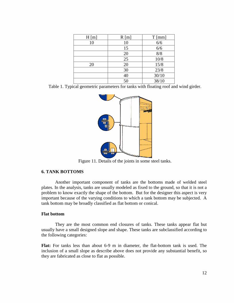
Typical dimensions of tanks with a wind girder and floating roof are listed in Table 1 as a guidance. The values of the thickness t indicate a variation from bottom to top of the shell.
12
H [m] R [m] T [mm] 10 10 6/6 15 6/6 20 8/8 25 10/8
20 20 15/8 30 23/8 40 30/10 50 38/10
Table 1. Typical geometric parameters for tanks with floating roof and wind girder.
Figure 11. Details of the joints in some steel tanks.
6. TANK BOTTOMS
Another important component of tanks are the bottoms made of welded steel
plates. In the analysis, tanks are usually modeled as fixed to the ground, so that it is not a problem to know exactly the shape of the bottom. But for the designer this aspect is very important because of the varying conditions to which a tank bottom may be subjected. A tank bottom may be broadly classified as flat bottom or conical. Flat bottom
They are the most common end closures of tanks. These tanks appear flat but usually have a small designed slope and shape. These tanks are subclassified according to the following categories: Flat: For tanks less than about 6-9 m in diameter, the flat-bottom tank is used. The inclusion of a small slope as describe above does not provide any substantial benefit, so they are fabricated as close to flat as possible.

13
Cone up: These bottoms are built with a high point in the center of the tank. Crowning the foundation and constructing the tank on the crown accomplish this. The slope is limited to about 25 to 50 mm per 3 m run. Cone down: The cone-down design slopes toward the center of the tank. Usually, there is a collection sump at the center. It is very effective for water removal from tanks. This design is inherently more complex because it requires a sump, underground piping, and an external sump outside the tank. Single slope: This design uses a planar bottom but it is tilted slightly to one side. This allows for drainage to be directed to the low point on the perimeter, where it may be effectively collected. Since there is a constant rise across the diameter of the tank, the difference in elevation from one side to the other can be quite large. Therefore, this design is usually limited to about 30 m. Conical bottom
The second type is the conical bottom. The designers often use it to provide a complete drainage or even removal of solids. Since these types of tanks are more costly, they are limited to the smaller sizes and are often found in the chemical industry or in processing plants. 7. FOUNDATIONS OF TANKS
This section applies to the tanks considered in this study, i.e. cylindrical tanks with
uniformly supported flat bottoms. A geotechnical study of the site is required in the design of the foundation; however, in many cases (especially for tanks located in coastal areas) the soils are susceptible to have uniform or differential settlements. The buckling of the shell due to the foundation settlement is considered in detail in one of the chapters of this report.
While it is difficult to classify all possible foundation types for storage tanks, some general types have proved to be most common for specific applications. Foundation types may be broken into several classifications in generally increasing order of costs: Compact soil foundations: These foundations can be used where the soil quality and bearing capacity are good. Generally, the top 7 to 15 cm of soil is removed and replaced with a sand or granular backfill. These are often called sand pad foundations, laid directly on earth. The advantage of this type of foundation is the relatively low cost. Crushed-stone ringwall foundations: This design happens to incorporate a leak detection system. While it costs less than the concrete ringwall, it has many of the advantage of the concrete ringwall. It provides uniform support of the tank bottom by dissipating concentrated loads in a granular pattern. Catastrophic failure of the bottom is possible if a leak starts and washes out the underlying support. Concrete ringwall foundations: The concrete ringwall foundation is so called because of its appearance. It is used in foundations for tanks of a diameter of at least 10 m or more. Some of the tanks with roof studied in this report are made. In the large-diameter

14
tanks this is usually the most cost-effective reinforced concrete foundation, with many advantages such as reducing the probabilities of settlements failures. Slab foundations: The concrete slab foundation has the advantages of the concrete ringwall but is usually limited to tanks with diameters less than 10 m. Often the edge of the slab will be sufficiently thick to provide for anchorage. A slab foundation is very versatile, but its high cost limits it to use in small tanks. The slab provides a level and plane-working surface that facilitates rapid field erection.
Figure 12. New tank constructed in 2000 at Craney Island, VA. Diameter 45.7 m, height 15.9 m, there is a ring stiffener at 10.5 m. (R/L=1.44). This tank stores up to 6.3 million gallons of jet fuel and can have a
weight of 50 million pounds. Pile-supported foundations: The pile-supported foundation is usually found where the soil bearing pressures are very low. Examples might be river deltas and land adjacent to bays. They are also used where high foundation uplift forces are encountered resulting from internal pressure or seismic loading. The tank shown in Figure 12 has a concrete slab and 432 piles supporting it. 8. MATERIALS Tanks are constructed from a number of different materials based upon the availability and cost of the material, ease of fabrication, resistance to corrosion, compatibility with the fluid stored. Sometimes specialized composites and techniques are used in tank construction, but these are the exception. Carbon steel, or mild steel, is by far the most common material for tank construction in Puerto Rico.2 This material is readily available, and because of the ease with which it is fabricated, machined, formed, and welded, it results in low overall costs. The material properties most commonly assumed for modeling are a modulus of elasticity of 2.068 x 10¹¹ N/m2, Poisson’s ratio of 0.3, mass density of 7849.7 kg/m3 , and yield strength of 2.156 x 10⁸ N/m2.
2 We confirmed this information during the field trips made around the industrial areas of Puerto Rico, including the south (Peñuelas, Guayanilla) and east (Yabucoa) regions of the island.
15
Stainless steel, usually the austenitic group of stainless steels, is an important material used for storage of corrosive liquids. Although the material cost is significantly more than that of steel, it has the same ease of availability as carbon steel. Fiberglass reinforced polymers (FRP) tanks are noted for their resistance to chemicals where stainless steel or aluminum tanks are not acceptable. However, the fabrication and construction techniques are somewhat more specialized than those for metals fabrication. Aluminum tanks are suitable for a limited number of materials. It is the less common metal used to build tanks. These tanks remain ductile at temperatures much lower than those of carbon steel. However, nickel steels and stainless steels have largely supplanted the market for aluminum tanks. Concrete tanks have been used in the water and sewage treatment business for a long time. However, they are outside the scope of this work.
Tanks made of metal materials such as carbon steel, stainless steel and aluminum are very prone to failure under natural hazards. Carbon steels used for storage tanks have specified minimum yield strengths of approximately 200 to 400 GPa. The principles of material selection are subdivided in the following engineering considerations, such as experience, code requirements, brittle fracture and corrosion.
Local engineers experience is very important at the time of choosing the material to design the tank. Probably it is the most common way of selecting steel that is appropriate for the tank and its service conditions is to rely on past experience with similar conditions.
Code requirements that govern tank designs often have very specific material selection requirements and limitations. Most modern codes include provisions in the material selection criteria that ensure materials with sufficient toughness under the service conditions to prevent brittle fracture. • The susceptibility of the material to brittle fracture is also one of the most important
material selection considerations. Brittle fracture is the tensile failure of a material showing little deformation or yielding. Brittle fractures typically start at a flaw and can propagate at high speeds, resulting in catastrophic failures.
• Corrosive effects in tanks may be divided into internal and external ones. The most common is the external corrosion that is usually minimized by the used of coatings for carbon steel tanks.
• The selection of a design metal temperature is important in ensuring that materials are selected which are tough enough to prevent brittle fractures under the service conditions.
• Ensuring a material with adequate toughness. One way to ensure that a selected steel has adequate toughness for the design metal temperature of the tank is to proof-test each plate by impact toughness testing samples at or below the design metal temperature (DMT).
9. TANK FARMS
Tanks are usually part of industrial plants or infrastructure facilities and often there are groups of closely spaced tanks. Figure 13 shows a group of tanks at Craney

16
Island, VA (Shehane 2001). This is the largest storage plant of fuel of the US Navy, and includes 60 tanks. Four very large tanks were added in the last five years, one of which is shown in Figure 12. The typical separation between tanks is in the order of 2 to 2.5 times the diameter of the largest tank.
Figure 13. Tank farm in Craney Island, VA, with more than 60 tanks, some aboveground and some belowground.
10. CODES AND DESIGN CONSIDERATIONS Industry standards and codes have been developed primarily on a voluntary basis by national standards-setting bodies by industries affected by them. Because the standards-setting bodies in most cases represent the interests of all parties, they must be consensus standards. The purpose of this standards and codes has been to provide acceptable, practical, and useful standards that ensure quality, safety, and reliability in equipment, practices, operations, or designs.
Most of the organizations produce different levels of standards, which can be generalized into the following basic categories: • Standards: These are considered to be mandatory practices that must be complied
with, so that the equipment manufactured may be considered in compliance or may be marked as complying with the standard. Standards are also often called codes.
• Recommended Practices: These are advisory documents that provide technological background and practices, which may be useful for the specific application at hand. They are not mandatory.

17
• Publications or bulletins: These are primarily for the purpose of informing the user of general aspects of the industry technology or practices.
• Specifications: They are considered interchangeable with standards. Specifications may also be a component of standards or codes. Many organizations have contributed in some way to storage tank technology. The
most important ones are: • The American Petroleum Institute (API). • American Society of Mechanical Engineers (ASME). • The fire protection organizations and codes (application and jurisdiction of U.S.
fire codes): Uniform Fire Code (UFC) and National Fire Protection Association (NFPA).
Tests are performed on tanks following the construction. The tanks are filled with
water according to a specified sequence with increments every ten days. The settlement of the foundation is measured under this initial condition. REFERENCES API Standard 653 (1991). Tank inspection, repair, alteration and reconstruction, First
Edition, American Petroleum Institute, Washington. Bell, R. A. and Iwakiri, J. (1980). Settlement comparison used in tank-failure study,
ASCE Journal of the Geotechnical Division, vol. 106(GT2), pp. 153-169. BS 2654 (1989). Manufacture of vertical steel welded non-refrigerated storage tanks
with butt-welded shells for the petroleum industry, British Standard Institution, London.
Kamyab, H. and Palmer, S. C. (1989). Analysis of displacements and stresses in oil storage tanks caused by differential settlement, Proc. Inst. Mechanical Engineers, UK, vol. 203(C1), pp. 61-70.
Myers, P. E. (1997). Aboveground Storage Tanks, McGraw-Hill, New York. Shehane, W. (2001). Updated containment on Craney Island, Geotechnical Fabrics
Report, vol. 19(6), pp. 36-37. Superior Tank Co. (2000) http://www.superiortank.com/brochure/pdf/brochurePDF.htm Temcor Co. (2002) www.temcor.com