Embed Size (px)
Citation preview
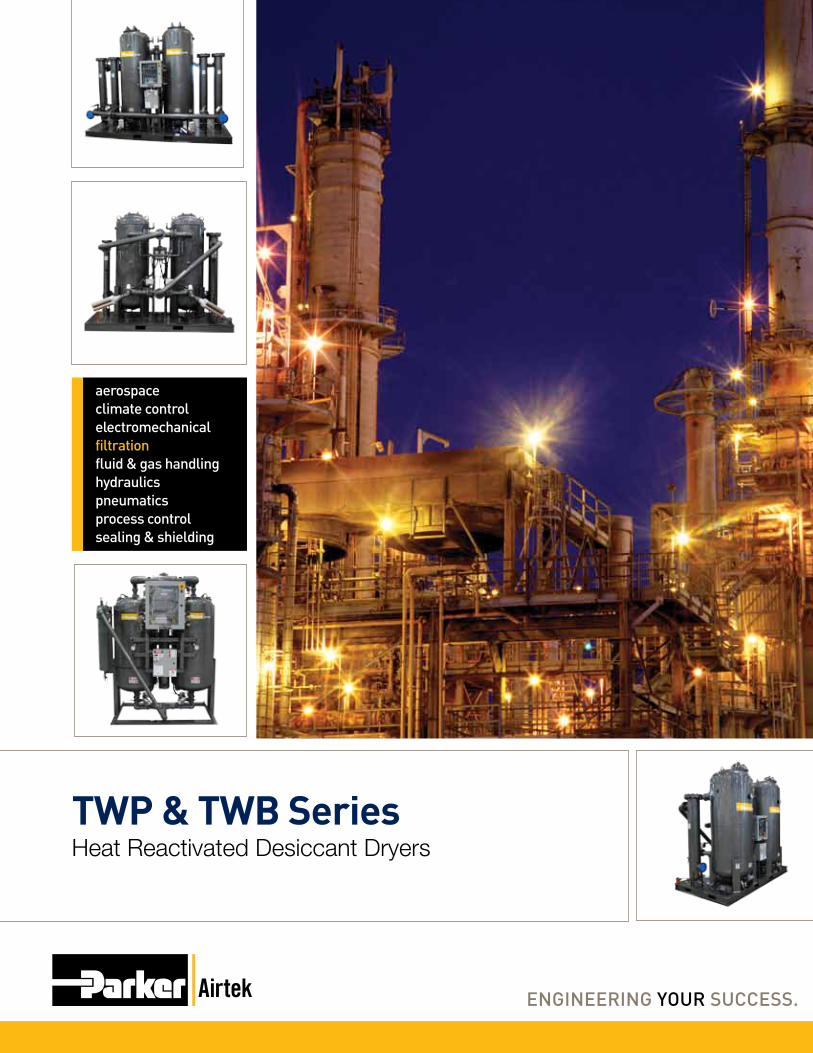
TWP & TWB SeriesHeat Reactivated Desiccant Dryers
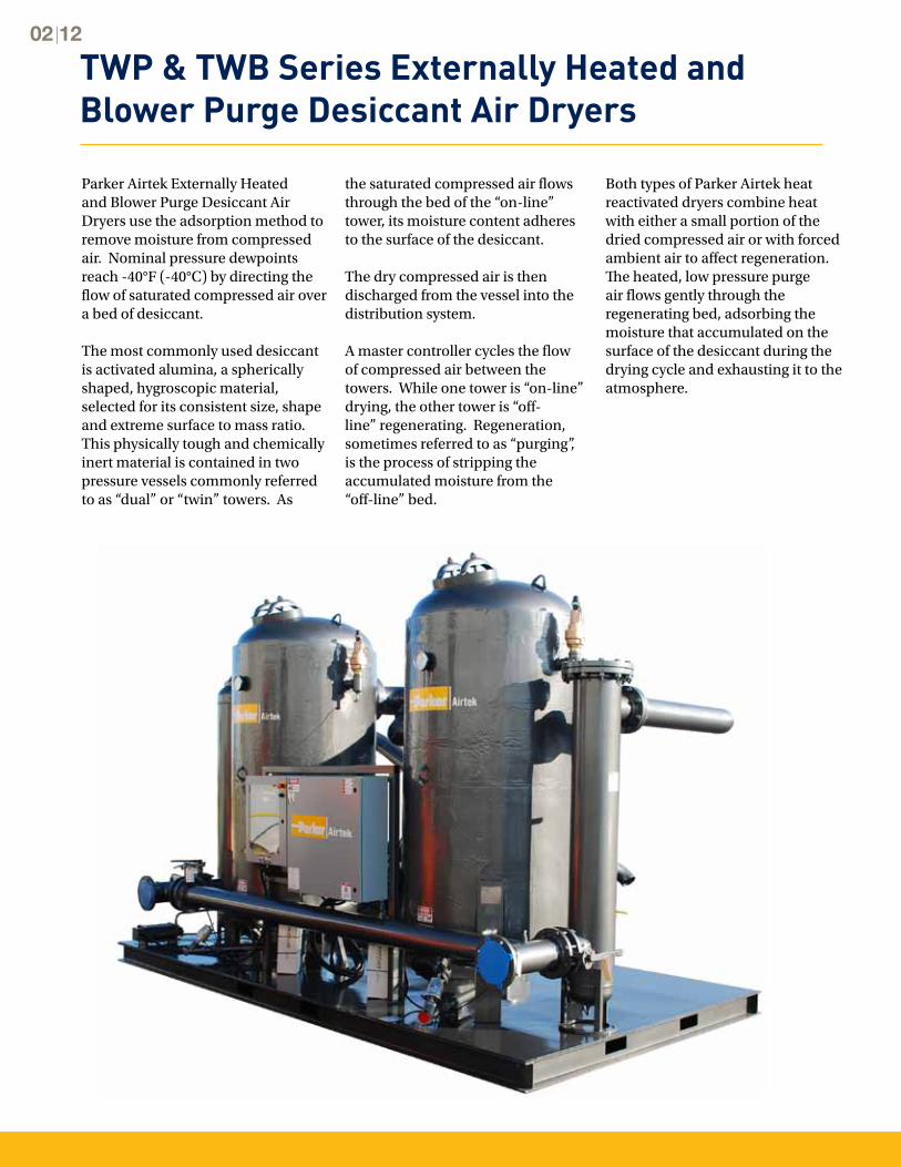
TWP & TWB Series Externally Heated and Blower Purge Desiccant Air Dryers
Parker Airtek Externally Heated and Blower Purge Desiccant Air Dryers use the adsorption method to remove moisture from compressed air. Nominal pressure dewpoints reach -40°F (-40°C) by directing the flow of saturated compressed air over a bed of desiccant.
The most commonly used desiccant is activated alumina, a spherically shaped, hygroscopic material, selected for its consistent size, shape and extreme surface to mass ratio. This physically tough and chemically inert material is contained in two pressure vessels commonly referred to as “dual” or “twin” towers. As
the saturated compressed air flows through the bed of the “on-line” tower, its moisture content adheres to the surface of the desiccant. The dry compressed air is then discharged from the vessel into the distribution system.
A master controller cycles the flow of compressed air between the towers. While one tower is “on-line” drying, the other tower is “off-line” regenerating. Regeneration, sometimes referred to as “purging”, is the process of stripping the accumulated moisture from the “off-line” bed.
Both types of Parker Airtek heat reactivated dryers combine heat with either a small portion of the dried compressed air or with forced ambient air to affect regeneration. The heated, low pressure purge air flows gently through the regenerating bed, adsorbing the moisture that accumulated on the surface of the desiccant during the drying cycle and exhausting it to the atmosphere.
02 12
www.parker.com/faf
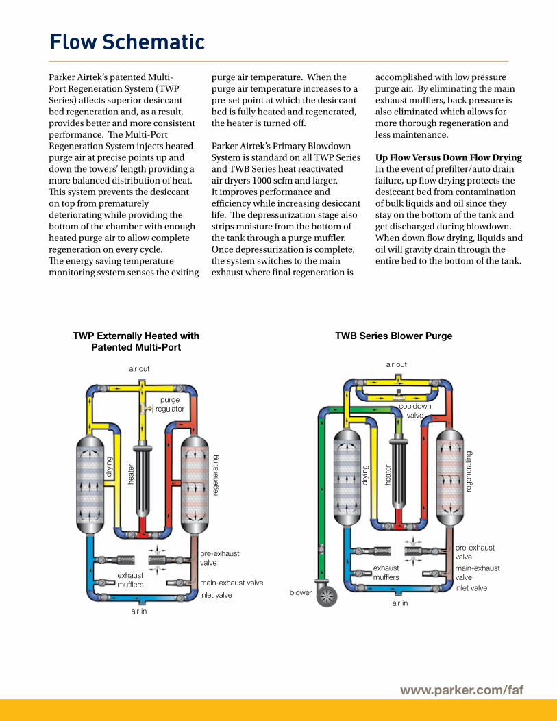
Flow SchematicParker Airtek’s patented Multi-Port Regeneration System (TWP Series) affects superior desiccant bed regeneration and, as a result, provides better and more consistent performance. The Multi-Port Regeneration System injects heated purge air at precise points up and down the towers’ length providing a more balanced distribution of heat. This system prevents the desiccant on top from prematurely deteriorating while providing the bottom of the chamber with enough heated purge air to allow complete regeneration on every cycle. The energy saving temperature monitoring system senses the exiting
TWP Externally Heated with Patented Multi-Port
pre-exhaust valve
main-exhaust valve
air in
exhaustmufflers
dryi
ng
heat
er
purgeregulator
air out
inlet valve
rege
nera
ting
TWB Series Blower Purge
pre-exhaust valve
main-exhaustvalve
air in
exhaustmufflers
blower
dryi
ng
heat
er
rege
nera
ting
cooldownvalve
air out
inlet valve
purge air temperature. When the purge air temperature increases to a pre-set point at which the desiccant bed is fully heated and regenerated, the heater is turned off.
Parker Airtek’s Primary Blowdown System is standard on all TWP Series and TWB Series heat reactivated air dryers 1000 scfm and larger. It improves performance and efficiency while increasing desiccant life. The depressurization stage alsostrips moisture from the bottom of the tank through a purge muffler. Once depressurization is complete, the system switches to the main exhaust where final regeneration is
accomplished with low pressure purge air. By eliminating the main exhaust mufflers, back pressure is also eliminated which allows for more thorough regeneration and less maintenance.
Up Flow Versus Down Flow DryingIn the event of prefilter/auto drain failure, up flow drying protects the desiccant bed from contamination of bulk liquids and oil since they stay on the bottom of the tank and get discharged during blowdown. When down flow drying, liquids and oil will gravity drain through the entire bed to the bottom of the tank.
04 12
Quick Glance Operational Status
all system okREGENERATING RIGHT coolING 11:0728 DEW POINT --40°F
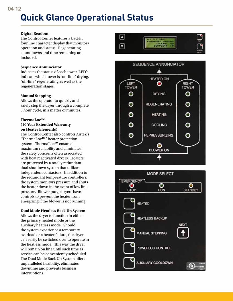
Digital ReadoutThe Control Center features a backlit four line character display that monitors operation and status. Regenerating countdowns and time remaining are included.
Sequence Annunciator Indicates the status of each tower. LED’s indicate which tower is “on-line” drying, “off-line” regenerating as well as the regeneration stages.
Manual Stepping Allows the operator to quickly and safely step the dryer through a complete 8 hour cycle, in a matter of minutes.
ThermaLocTM
(10 Year Extended Warranty on Heater Elements)The Control Center also controls Airtek’s “ThermaLocTM” heater protection system. ThermaLocTM ensures maximum reliability and eliminates the safety concerns often associated with heat reactivated dryers. Heaters are protected by a totally redundant dual shutdown system that utilizes independent contactors. In addition to the redundant temperature controllers, the system monitors pressure and shuts the heater down in the event of low line pressure. Blower purge dryers have controls to prevent the heater from energizing if the blower is not running.
Dual Mode Heatless Back Up System Allows the dryer to function in either the primary heated mode or the auxiliary heatless mode. Should the system experience a temporary overload or a heater failure, the dryer can easily be switched over to operate in the heatless mode. This way the dryer will remain on line until such time as service can be conveniently scheduled. The Dual Mode Back Up System offers unparalleled flexibility, eliminates downtime and prevents business interruptions.
www.parker.com/faf
High Performance Components
Equipment
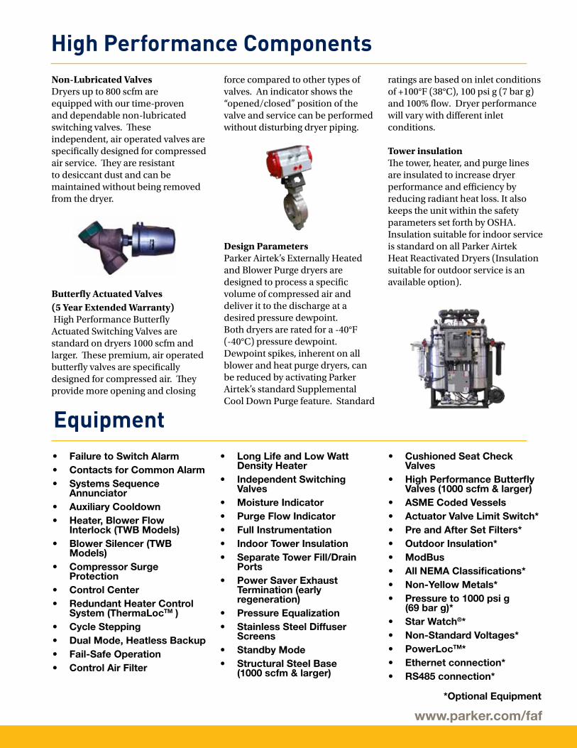
Non-Lubricated Valves Dryers up to 800 scfm are equipped with our time-proven and dependable non-lubricated switching valves. These independent, air operated valves are specifically designed for compressed air service. They are resistant to desiccant dust and can be maintained without being removed from the dryer.
Butterfly Actuated Valves(5 Year Extended Warranty) High Performance Butterfly Actuated Switching Valves are standard on dryers 1000 scfm and larger. These premium, air operated butterfly valves are specifically designed for compressed air. They provide more opening and closing
force compared to other types of valves. An indicator shows the “opened/closed” position of the valve and service can be performed without disturbing dryer piping.
Design ParametersParker Airtek’s Externally Heated and Blower Purge dryers are designed to process a specific volume of compressed air and deliver it to the discharge at a desired pressure dewpoint. Both dryers are rated for a -40°F (-40°C) pressure dewpoint. Dewpoint spikes, inherent on all blower and heat purge dryers, can be reduced by activating Parker Airtek’s standard Supplemental Cool Down Purge feature. Standard
ratings are based on inlet conditions of +100°F (38°C), 100 psi g (7 bar g) and 100% flow. Dryer performance will vary with different inlet conditions. Tower insulationThe tower, heater, and purge lines are insulated to increase dryer performance and efficiency by reducing radiant heat loss. It also keeps the unit within the safety parameters set forth by OSHA. Insulation suitable for indoor service is standard on all Parker Airtek Heat Reactivated Dryers (Insulation suitable for outdoor service is an available option).
• Failure to Switch Alarm• Contacts for Common Alarm• Systems Sequence
Annunciator • Auxiliary Cooldown• Heater, Blower Flow
Interlock (TWB Models)• Blower Silencer (TWB
Models)• Compressor Surge
Protection• Control Center• Redundant Heater Control
System (ThermaLocTM )• Cycle Stepping• Dual Mode, Heatless Backup• Fail-Safe Operation• Control Air Filter
• Long Life and Low Watt Density Heater
• Independent Switching Valves
• Moisture Indicator• Purge Flow Indicator• Full Instrumentation• Indoor Tower Insulation• Separate Tower Fill/Drain
Ports • Power Saver Exhaust
Termination (early regeneration)
• Pressure Equalization• Stainless Steel Diffuser
Screens • Standby Mode• Structural Steel Base
(1000 scfm & larger)
• Cushioned Seat Check Valves
• High Performance Butterfly Valves (1000 scfm & larger)
• ASME Coded Vessels • Actuator Valve Limit Switch*• Pre and After Set Filters*• Outdoor Insulation*• ModBus• All NEMA Classifications*• Non-Yellow Metals*• Pressure to 1000 psi g
(69 bar g)*• Star Watch®*• Non-Standard Voltages*• PowerLocTM*• Ethernet connection*• RS485 connection*
*Optional Equipment
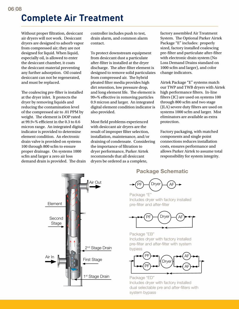
Complete Air TreatmentWithout proper filtration, desiccant air dryers will not work. Desiccant dryers are designed to adsorb vapor from compressed air; they are not designed for liquid. When liquid, especially oil, is allowed to enter the desiccant chamber, it coats the desiccant material preventing any further adsorption. Oil coated desiccant can not be regenerated, and must be replaced.
The coalescing pre-filter is installed at the dryer inlet. It protects the dryer by removing liquids and reducing the contamination level of the compressed air to .01 PPM by weight. The element is DOP rated at 99.9+% efficient in the 0.3 to 0.6 micron range. An integrated digital indicator is provided to determine element condition. An electronic drain valve is provided on systems 100 through 800 scfm to ensure proper drainage. On systems 1000 scfm and larger a zero air loss demand drain is provided. The drain
controller includes push to test, drain alarm, and common alarm contact.
To protect downstream equipment from desiccant dust a particulate after-filter is installed at the dryer discharge. The after-filter element is designed to remove solid particulates from compressed air. The hybrid pleated filter media provides high dirt retention, low pressure drop, and long element life. The element is 99+% effective in removing particles 0.9 micron and larger. An integrated digital element condition indicator is also provided.
Most field problems experienced with desiccant air dryers are the result of improper filter selection, installation, maintenance, and/or draining of condensate. Considering the importance of filtration to dryer performance, Parker Airtek recommends that all desiccant dryers be ordered as a complete,
Package ”EB”Includes dryer with factory installed pre-filter and after-filter with system bypass
Dryer AFPF
Package “E”Includes dryer with factory installed pre-filter and after-filter
Dryer AFPF
Package “ED”Includes dryer with factory installed dual selectable pre and after-filters with system bypass
DryerPF
PF
AF
AF
Air InFirst Stage
1st Stage Drain
2nd Stage Drain
Second Stage
Element
Air Out
06 08
factory assembled Air Treatment System. The Optional Parker Airtek Package “E” includes: properly sized, factory installed coalescing pre-filter and particulate after-filter with electronic drain system (No Loss Demand Drains standard on 1000 scfm and larger), and color change indicators.
Airtek Package “E” systems match our TWP and TWB dryers with Airtek high performance filters. In-line filters (JC) are used on systems 100 through 800 scfm and two stage (JLA) severe duty filters are used on systems 1000 scfm and larger. Mist eliminators are available as extra protection.
Factory packaging, with matched components and single point connections reduces installation costs, ensures performance and allows Parker Airtek to assume total responsibility for system integrity.
Package Schematic
www.parker.com/faf
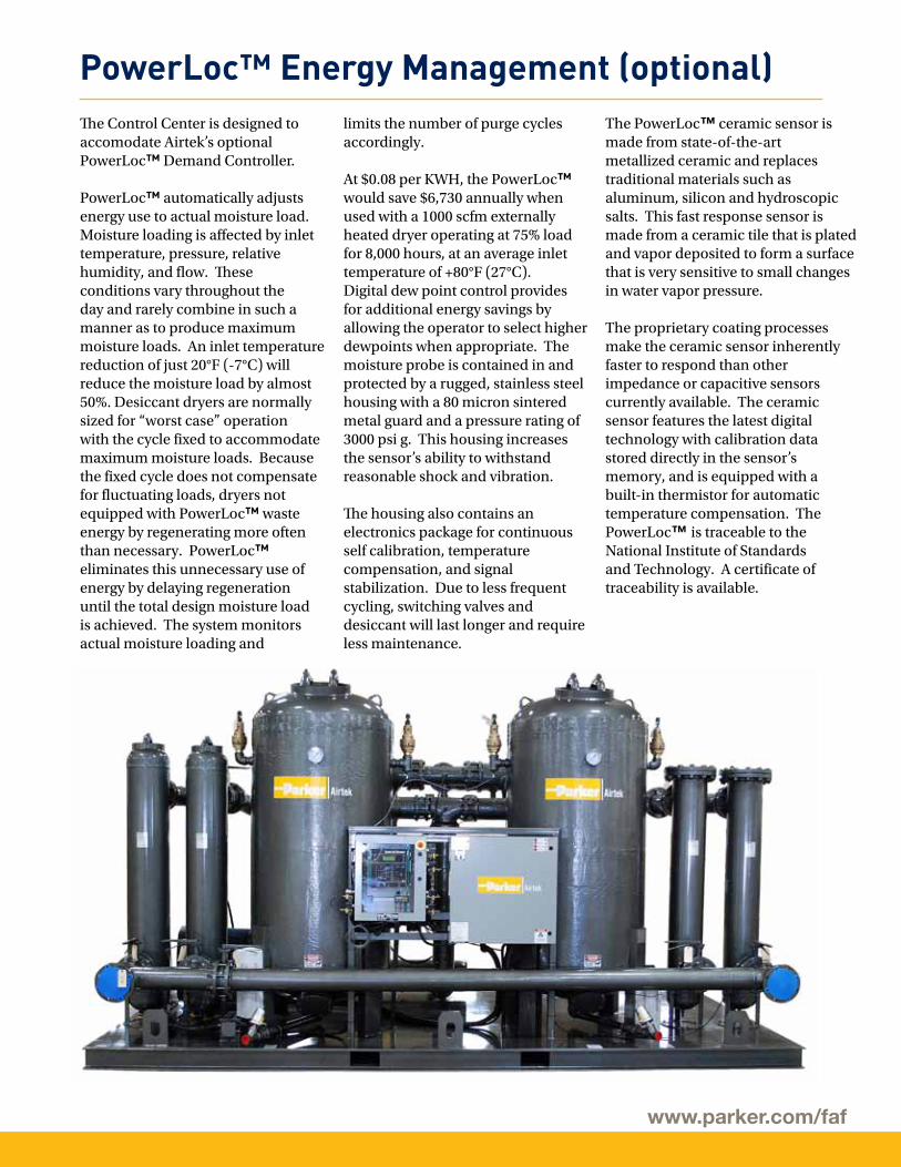
The Control Center is designed to accomodate Airtek’s optional PowerLoc™ Demand Controller.
PowerLoc™ automatically adjusts energy use to actual moisture load. Moisture loading is affected by inlet temperature, pressure, relative humidity, and flow. These conditions vary throughout the day and rarely combine in such a manner as to produce maximum moisture loads. An inlet temperature reduction of just 20°F (-7°C) will reduce the moisture load by almost 50%. Desiccant dryers are normally sized for “worst case” operation with the cycle fixed to accommodate maximum moisture loads. Because the fixed cycle does not compensate for fluctuating loads, dryers not equipped with PowerLoc™ waste energy by regenerating more often than necessary. PowerLoc™ eliminates this unnecessary use of energy by delaying regeneration until the total design moisture load is achieved. The system monitors actual moisture loading and
limits the number of purge cycles accordingly.
At $0.08 per KWH, the PowerLoc™ would save $6,730 annually when used with a 1000 scfm externally heated dryer operating at 75% load for 8,000 hours, at an average inlet temperature of +80°F (27°C). Digital dew point control provides for additional energy savings by allowing the operator to select higher dewpoints when appropriate. The moisture probe is contained in and protected by a rugged, stainless steel housing with a 80 micron sintered metal guard and a pressure rating of 3000 psi g. This housing increases the sensor’s ability to withstand reasonable shock and vibration.
The housing also contains an electronics package for continuous self calibration, temperature compensation, and signal stabilization. Due to less frequent cycling, switching valves and desiccant will last longer and require less maintenance.
PowerLoc™ Energy Management (optional)The PowerLoc™ ceramic sensor is made from state-of-the-art metallized ceramic and replaces traditional materials such as aluminum, silicon and hydroscopic salts. This fast response sensor is made from a ceramic tile that is plated and vapor deposited to form a surface that is very sensitive to small changes in water vapor pressure.
The proprietary coating processes make the ceramic sensor inherently faster to respond than other impedance or capacitive sensors currently available. The ceramic sensor features the latest digital technology with calibration data stored directly in the sensor’s memory, and is equipped with a built-in thermistor for automatic temperature compensation. The PowerLoc™ is traceable to the National Institute of Standards and Technology. A certificate of traceability is available.
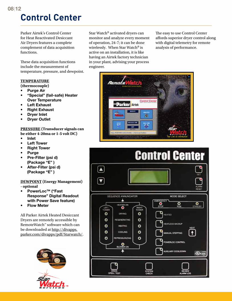
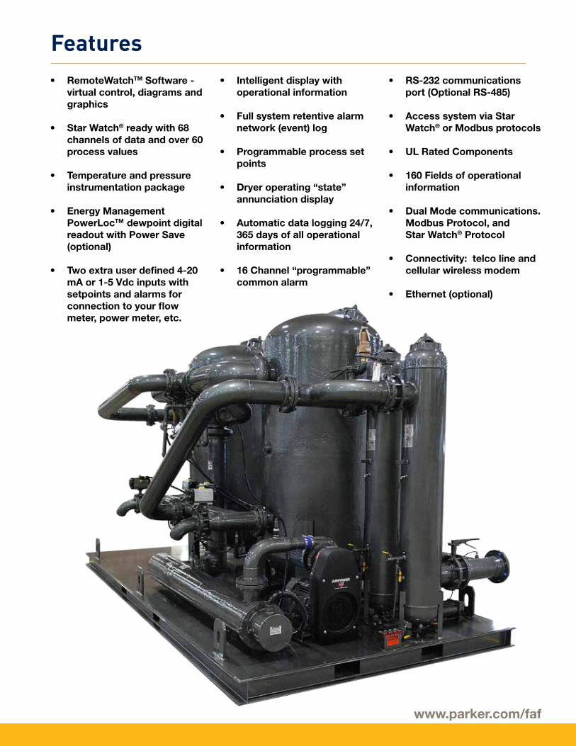
Control CenterParker Airtek’s Control Center for Heat Reactivated Desiccant Air Dryers features a complete complement of data acquisition functions.
These data acquisition functions include the measurement of temperature, pressure, and dewpoint.
TEMPERATURE (thermocouple)• Purge Air• “Special” (fail-safe) Heater
Over Temperature• Left Exhaust• Right Exhaust• Dryer Inlet • Dryer Outlet
PRESSURE (Transducer signals can be either 4-20ma or 1-5 volt DC)• Inlet• Left Tower• Right Tower• Purge• Pre-Filter (psi d) (Package “E” )• After-Filter (psi d) (Package “E” )
DEWPOINT (Energy Management) - optional• PowerLoc™ (“Fast
Response” Digital Readout with Power Save feature)
• Flow Meter
All Parker Airtek Heated Desiccant Dryers are remotely accessible by RemoteWatch™ software which can be downloaded at http://divapps.parker.com/divapps/pdf/Starwatch/.
08 12
Star Watch® activated dryers can monitor and analyze every moment of operation, 24-7; it can be done wirelessly. When Star Watch® is active on an installation, it is like having an Airtek factory technician in your plant, advising your process engineer.
The easy to use Control Center affords superior dryer control along with digital telemetry for remote analysis of performance.
www.parker.com/faf
• RemoteWatchTM Software - virtual control, diagrams and graphics
• Star Watch® ready with 68 channels of data and over 60 process values
• Temperature and pressure instrumentation package
• Energy Management PowerLocTM dewpoint digital readout with Power Save (optional)
• Two extra user defined 4-20 mA or 1-5 Vdc inputs with setpoints and alarms for connection to your flow meter, power meter, etc.
• Intelligent display with operational information
• Full system retentive alarm network (event) log
• Programmable process set points
• Dryer operating “state” annunciation display
• Automatic data logging 24/7, 365 days of all operational information
• 16 Channel “programmable” common alarm
• RS-232 communications port (Optional RS-485)
• Access system via Star Watch® or Modbus protocols
• UL Rated Components
• 160 Fields of operational information
• Dual Mode communications. Modbus Protocol, and Star Watch® Protocol
• Connectivity: telco line and cellular wireless modem
• Ethernet (optional)
Features
Engineering Data Specifications 10 12
MEMBER OF™
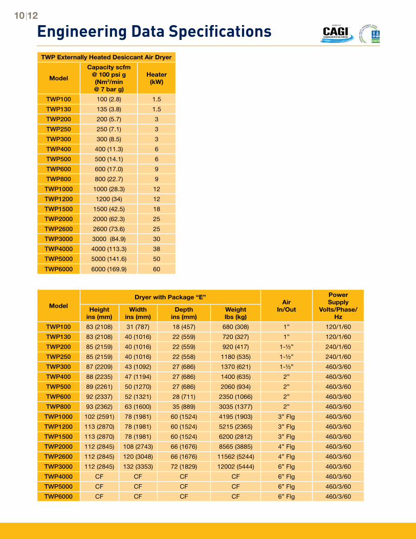
TWP Externally Heated Desiccant Air Dryer
Model
Capacity scfm@ 100 psi g(Nm3/min@ 7 bar g)
Heater(kW)
TWP100 100 (2.8) 1.5
TWP130 135 (3.8) 1.5
TWP200 200 (5.7) 3
TWP250 250 (7.1) 3
TWP300 300 (8.5) 3
TWP400 400 (11.3) 6
TWP500 500 (14.1) 6
TWP600 600 (17.0) 9
TWP800 800 (22.7) 9
TWP1000 1000 (28.3) 12
TWP1200 1200 (34) 12
TWP1500 1500 (42.5) 18
TWP2000 2000 (62.3) 25
TWP2600 2600 (73.6) 25
TWP3000 3000 (84.9) 30
TWP4000 4000 (113.3) 38
TWP5000 5000 (141.6) 50
TWP6000 6000 (169.9) 60
ModelDryer with Package “E”
AirIn/Out
PowerSupply
Volts/Phase/Hz
Heightins (mm)
Widthins (mm)
Depthins (mm)
Weightlbs (kg)
TWP100 83 (2108) 31 (787) 18 (457) 680 (308) 1” 120/1/60
TWP130 83 (2108) 40 (1016) 22 (559) 720 (327) 1” 120/1/60
TWP200 85 (2159) 40 (1016) 22 (559) 920 (417) 1-½” 240/1/60
TWP250 85 (2159) 40 (1016) 22 (558) 1180 (535) 1-½” 240/1/60
TWP300 87 (2209) 43 (1092) 27 (686) 1370 (621) 1-½” 460/3/60
TWP400 88 (2235) 47 (1194) 27 (686) 1400 (635) 2” 460/3/60
TWP500 89 (2261) 50 (1270) 27 (686) 2060 (934) 2” 460/3/60
TWP600 92 (2337) 52 (1321) 28 (711) 2350 (1066) 2” 460/3/60
TWP800 93 (2362) 63 (1600) 35 (889) 3035 (1377) 2” 460/3/60
TWP1000 102 (2591) 78 (1981) 60 (1524) 4195 (1903) 3” Flg 460/3/60
TWP1200 113 (2870) 78 (1981) 60 (1524) 5215 (2365) 3” Flg 460/3/60
TWP1500 113 (2870) 78 (1981) 60 (1524) 6200 (2812) 3” Flg 460/3/60
TWP2000 112 (2845) 108 (2743) 66 (1676) 8565 (3885) 4” Flg 460/3/60
TWP2600 112 (2845) 120 (3048) 66 (1676) 11562 (5244) 4” Flg 460/3/60
TWP3000 112 (2845) 132 (3353) 72 (1829) 12002 (5444) 6” Flg 460/3/60
TWP4000 CF CF CF CF 6” Flg 460/3/60
TWP5000 CF CF CF CF 6” Flg 460/3/60
TWP6000 CF CF CF CF 6” Flg 460/3/60
www.parker.com/faf
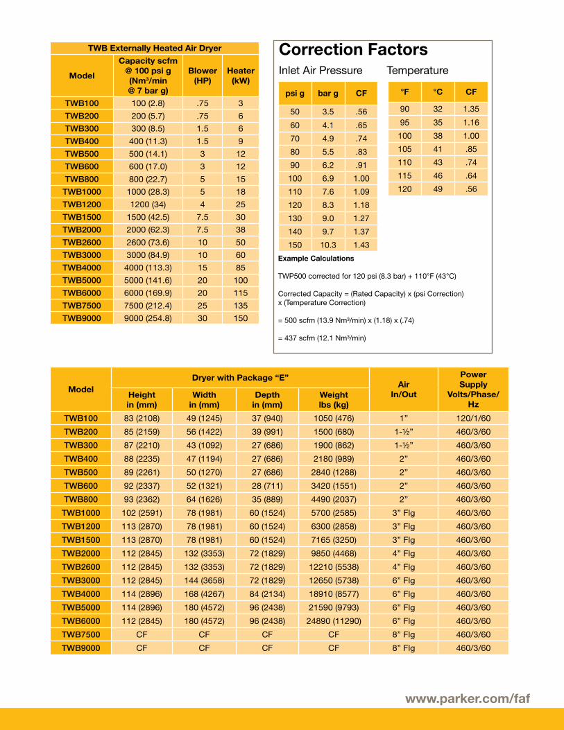
Example Calculations
TWP500 corrected for 120 psi (8.3 bar) + 110°F (43°C)
Corrected Capacity = (Rated Capacity) x (psi Correction) x (Temperature Correction)
= 500 scfm (13.9 Nm³/min) x (1.18) x (.74)
= 437 scfm (12.1 Nm³/min)
psi g bar g CF
50 3.5 .56
60 4.1 .65
70 4.9 .74
80 5.5 .83
90 6.2 .91
100 6.9 1.00
110 7.6 1.09
120 8.3 1.18
130 9.0 1.27
140 9.7 1.37
150 10.3 1.43
°F °C CF
90 32 1.35
95 35 1.16
100 38 1.00
105 41 .85
110 43 .74
115 46 .64
120 49 .56
Correction FactorsInlet Air Pressure Temperature
TWB Externally Heated Air Dryer
Model
Capacity scfm@ 100 psi g(Nm3/min@ 7 bar g)
Blower (HP)
Heater(kW)
TWB100 100 (2.8) .75 3
TWB200 200 (5.7) .75 6
TWB300 300 (8.5) 1.5 6
TWB400 400 (11.3) 1.5 9
TWB500 500 (14.1) 3 12
TWB600 600 (17.0) 3 12
TWB800 800 (22.7) 5 15
TWB1000 1000 (28.3) 5 18
TWB1200 1200 (34) 4 25
TWB1500 1500 (42.5) 7.5 30
TWB2000 2000 (62.3) 7.5 38
TWB2600 2600 (73.6) 10 50
TWB3000 3000 (84.9) 10 60
TWB4000 4000 (113.3) 15 85
TWB5000 5000 (141.6) 20 100
TWB6000 6000 (169.9) 20 115
TWB7500 7500 (212.4) 25 135
TWB9000 9000 (254.8) 30 150
ModelDryer with Package “E”
AirIn/Out
PowerSupply
Volts/Phase/Hz
Heightin (mm)
Widthin (mm)
Depthin (mm)
Weightlbs (kg)
TWB100 83 (2108) 49 (1245) 37 (940) 1050 (476) 1” 120/1/60
TWB200 85 (2159) 56 (1422) 39 (991) 1500 (680) 1-½” 460/3/60
TWB300 87 (2210) 43 (1092) 27 (686) 1900 (862) 1-½” 460/3/60
TWB400 88 (2235) 47 (1194) 27 (686) 2180 (989) 2” 460/3/60
TWB500 89 (2261) 50 (1270) 27 (686) 2840 (1288) 2” 460/3/60
TWB600 92 (2337) 52 (1321) 28 (711) 3420 (1551) 2” 460/3/60
TWB800 93 (2362) 64 (1626) 35 (889) 4490 (2037) 2” 460/3/60
TWB1000 102 (2591) 78 (1981) 60 (1524) 5700 (2585) 3” Flg 460/3/60
TWB1200 113 (2870) 78 (1981) 60 (1524) 6300 (2858) 3” Flg 460/3/60
TWB1500 113 (2870) 78 (1981) 60 (1524) 7165 (3250) 3” Flg 460/3/60
TWB2000 112 (2845) 132 (3353) 72 (1829) 9850 (4468) 4” Flg 460/3/60
TWB2600 112 (2845) 132 (3353) 72 (1829) 12210 (5538) 4” Flg 460/3/60
TWB3000 112 (2845) 144 (3658) 72 (1829) 12650 (5738) 6” Flg 460/3/60
TWB4000 114 (2896) 168 (4267) 84 (2134) 18910 (8577) 6” Flg 460/3/60
TWB5000 114 (2896) 180 (4572) 96 (2438) 21590 (9793) 6” Flg 460/3/60
TWB6000 112 (2845) 180 (4572) 96 (2438) 24890 (11290) 6” Flg 460/3/60
TWB7500 CF CF CF CF 8” Flg 460/3/60
TWB9000 CF CF CF CF 8” Flg 460/3/60
Parker Hannifin CorporationFinite Airtek Filtration Division4087 Walden AvenueLancaster, NY 14086phone 716 686 6400www.parker.com/faf
© 2011 Parker Hannifin Corporation. Product names are trademarks or registered trademarks of their respective companies. Catalog: TWP & TWB Series Rev 003 NA 07/2012
North AmericaCompressed Air TreatmentFiltration & Separation/BalstonHaverhill, MA 978 858 0505 www.parker.com/balston
Finite Airtek FiltrationAirtek/domnick hunter/ZanderLancaster, NY 716 686 6400 www.parker.com/faf
Finite Airtek Filtration/FiniteOxford, MI 248 628 6400 www.parker.com/finitefilter
Engine Filtration & Water PurificationRacor Modesto, CA 209 521 7860 www.parker.com/racor
RacorHolly Springs, MS 662 252 2656 www.parker.com/racor
RacorBeaufort, SC 843 846 3200 www.parker.com/racor
Racor – Village Marine Tec.Gardena, CA 310 516 9911 desalination.parker.com
Hydraulic FiltrationHydraulic FilterMetamora, OH 419 644 4311 www.parker.com/hydraulicfilter
Process Filtration domnick hunter Process FiltrationOxnard, CA 805 604 3400 www.parker.com/processfiltration
Worldwide Filtration Manufacturing LocationsEuropeCompressed Air Treatmentdomnick hunter Filtration & Separation Gateshead, England +44 (0) 191 402 9000 www.parker.com/dhfns
Parker Gas SeparationsEtten-Leur, Netherlands +31 76 508 5300www.parker.com/dhfns
Hiross Zander Padova Business Unit Padova, Italy +39 049 9712 111 www.parker.com/hzd
Hiross ZanderEssen Business Unit Essen, Germany +49 2054 9340 www.parker.com/hzd
Engine Filtration & Water PurificationRacor Dewsbury, England +44 (0) 1924 487 000 www.parker.com/rfde
Racor Research & DevelopmentStuttgart, Germany +49 (0)711 7071 290-10www.parker.com/rfde
Hydraulic FiltrationHydraulic Filter Arnhem, Holland +31 26 3760376 www.parker.com/hfde
Urjala Operation Urjala, Finland +358 20 753 2500 www.parker.com/hfde
Condition Monitoring Center Norfolk, England +44 1842 763 299 www.parker.com/hfde
Process Filtration domnick hunter Process FiltrationBirtley, England +44 (0) 191 410 5121 www.parker.com/processfiltration
Asia PacificAustralia Castle Hill, Australia +61 2 9634 7777 www.parker.com/australia
China Shanghai, China +86 21 5031 2525 www.parker.com/china
IndiaNavi Mumbai, India +91 22 651 370 8185 www.parker.com/india
Japan Tokyo, Japan +81 45 870 1522 www.parker.com/japan
Korea Hwaseon-City +82 31 359 0852 www.parker.com/korea
SingaporeJurong Town, Singapore +65 6887 6300 www.parker.com/singapore
Thailand Bangkok, Thailand +66 2 186 7000 www.parker.com/thailand
Latin AmericaParker Comercio Ltda. Filtration Division Sao Paulo, Brazil +55 12 4009 3500 www.parker.com/br
Pan American Division Miami, FL 305 470 8800 www.parker.com/panam
AfricaAeroport Kempton Park, South Africa +27 11 9610700 www.parker.com/africa