Embed Size (px)
Citation preview
Volume 7, Number 4 (August 2014) p. 572-591 • ISSN 1983-4195
© 2014 IBRACON
The position of pipes and hoses for several installations still deserves special attention from designers mainly when the failure mode can be modi-fied due to changes in behavior. This work compares experimental results of six two-way reinforced concrete ribbed flat slabs with rectangular holes close to the column and without shear reinforcement with the estimates obtained from codes ACI 318 and NBR 6118 equations. All slabs were casted and tested in the Civil Engineering Laboratory of UFPA and had dimensions of 1.800 mm x 1.800 mm x 150 mm and were submitted to central loading applied through 120 mm side square steel plates simulating the columns. EPS was used as inert material and the ribs were spaced 250 mm with 130 mm height and 75 mm average wide. The results showed that the codes’ shear equations estimates agree when the ribs are considered as beam and also for punching shear, but trend to be safer when the slabs present two shafts.
Keywords: flat slab, ribbed slab, shaft, holes, shear, punching.
A passagem de tubulações em elementos estruturais ainda merece atenção especial dos projetistas, principalmente quando o modo de ruptura dos mesmos pode ser alterado devido às mudanças em seus comportamentos. Este trabalho compara os resultados experimentais obtidos para 06 (seis) lajes lisas nervuradas bidirecionais em concreto armado, com furos retangulares adjacentes aos pilares e sem armadura de cisalha-mento, com as estimativas das formulações dadas pelas normas ACI 318 e NBR 6118. As lajes foram moldadas e ensaiadas no Laboratório de Engenharia Civil da UFPA e apresentaram dimensões de 1.800 mm x 1.800 mm x 150 mm, sendo submetidas a carregamento central em placas quadradas que simularam pilares com 120 mm de lado. O material inerte entre as nervuras foi o EPS e o espaçamento entre as mesmas foi de 250 mm, com largura média de 75 mm e altura 130 mm. Os resultados mostraram que as normas convergem em suas estimativas de resistência ao cisalhamento, quando as nervuras são tratadas isoladamente como vigas, e também ao puncionamento, mas neste caso tendem a ser con-servadoras quando as lajes apresentam dois furos.
Palavras-chave: laje lisa, laje nervurada, puncionamento, furo, cisalhamento.
Two-way ribbed flat slabs with shafts
Lajes lisas nervuradas bidirecionais com furos
G. M. MATEUS a
A. J. AGUIAR a
M. P. FERREIRA a
D. R. C. OLIVEIRA a
a Universidade Federal do Pará, Belém, PA, Brasil.
Received: 30 Oct 2013 • Accepted: 25Mar 2014 • Available Online: 05 Aug 2014
Abstract
Resumo
1. Introduction
The implementation of structural systems with ribbed flat slabs is growing and motivates important questions about their structural response and resistance. Cases in which holes are located in the slab adjacent to the column are of special interest, as concentra-tion of shear stresses are likely to occur, what may reduce sig-nificantly the punching resistance of the slab-column connection. According to SOUZA and CUNHA (1998 ) [ 1 ], local failures in the slab-column connection can lead the hole building to ruin through progressive collapse, once punching is a brittle failure mode.In this context, it is important to evaluate the available normative recommendations for the design of this type of slab, since it is known that for specific design situations, as in the case of con-nections with columns with high rectangularity levels, some codes tend to overestimate the strength of the connection. In practice, this may contribute to major structural accidents such as occurred in July 2013 during the construction of the Rio Poty Shopping in Teresina, where approximately 50% of the structure collapsed and punching shear of the slabs, that had holes adjacent to the col-umns, was pointed as a possible cause.This paper presents experimental results of tests in six two-way reinforced concrete ribbed flat slabs. One of the slabs had no holes and served as reference to the other five slabs, which had holes adjacent to the column. Experimental results were compared to normative estimates using recommendations presented by ACI 318 (ACI, 2008) [2] and NBR 6118 (ABNT, 2007) [3]. Slabs were cast without shear reinforcement, thus shear strength is mainly a function of the compressive strength of concrete and of the flexural reinforcement ratio of the slab.
2. Code provisions
The codes used in this research estimate the punching shear re-sistance of slabs with holes adjacent to the column in a similar way, differing only in the shape, length and position of the control perimeter. The criteria used to consider the influence of holes is similar in both ACI 318 and NBR 6118 and involve the reduction of the control perimeter by limiting its length, removing the portion of the perimeter between lines that are drawn from the center of the column to the vertices of the hole. The control perimeter is as-sumed to be 2·d from the column faces in NBR 6118 and 0.5·d in ACI 318, where d is the effective depth of the slab. Figure 1 shows
the control perimeters and the specific recommendations for slabs with holes presented by NBR 6118 and ACI 318. ACI 318 and NBR 6118 recommend that the punching resistance shall be calculated using equations 1 and 2, respectively.
(1)Vp=fc3
·u·d
(2)Vp=0,13· ( 1+ 200
d ) ·(100·ρ·fc)1/3·u·d
where,d is the effective depth of the slab;fc is the compressive strength of concrete;r is the flexural reinforcement ratio;u is the length of the control perimeter.To check the one-way shear resistance of the slabs two verifica-tions shall be made. In the first one, the one-way shear resistance shall be checked assuming that the ribs behave as beams. In the second one, the one-way shear resistance of the ribs shall be checked as slabs. ACI recommends Equation 1 for the first case and 50% of the values obtained using Equation 1 for the second situation. In this procedure, the length of the control perimeter (u) shall be substituted by the average width of the ribs (bw). The Bra-zilian code recommends equations 3 and 4 for these verifications.
(3)V=0,18· fck²3
·bw·d
(4)V= [0,08· fck²3
·(1,6-d
1000)·(1,2+40·ρ)] bw·d
The flexural strength of the slabs was estimated according to the
573IBRACON Structures and Materials Journal • 2014 • vol. 7 • nº 3
G. M. MATEUS | A. J. AGUIAR | M. P. FERREIRA | D. R. C. OLIVEIRA
Figure 1 – Control perimeter according to ACI 318 (left) and NBR 6118 (right)
574 IBRACON Structures and Materials Journal • 2014 • vol. 7 • nº 4
Two-way ribbed flat slabs with shafts
yield line theory developed by Johansen (1943) [4]. The procedure is to determinate the ultimate moment of resistance per unit width with Equation 5 and, assuming a collapse mechanism character-ized by the formation of linear plastic hinges, estimate the ultimate flexural load supported by the slab. The collapse mechanism ad-opted in this research was the same used by Oliveira (2003) [5] and is shown in Figure 2, yielding Equation 6 to estimate flexural strength of slabs. Specifically for slab L4, the collapse mechanism used for the other slabs was not optimal, resulting in high values, besides it did not match the experimental observations. In this case, it was used the same method employed for the calculation of beams, and the static scheme assumed the columns as a con-centrated load in the middle of a fixed beam with length of 240 mm.
(5)
÷÷ø
öççè
æ××-×××=
cf
ysfdysfum rr 5,012
(6)[ ] [ ]xexl
ya
uym
yeyl
xa
uxm
fP ×-××
+×-××
= 22
22
3. Experimental program
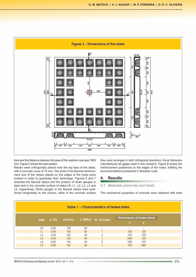
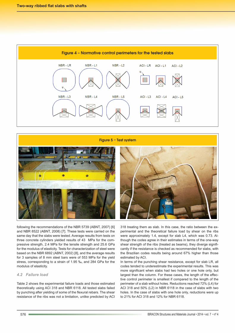
Six reinforced concrete ribbed flat slabs were tested in the labora-tory of civil engineering of Federal University of Pará. The slabs were square with sides of 1,800 mm and were 150 mm thick. The main variables were the position and size of the holes. A slab with-out holes was tested as reference to all others, which had holes adjacent to the column. Figure 3 and Table 1 present the main characteristics of tested slabs. Figure 4 shows the position of the holes in the vicinity of the columns for all slabs and their control pe-rimeter drawn according the recommendations presented by ACI and NBR 6118.The number and spacing of flexural rebars was the same for all slabs. The minor differences in the flexural reinforcement ratio () of the slabs, which varied between 0.42% and 0.46% as shown in Table 1, refers to changes in the effective depth of the slabs () after assembling the reinforcement. The values measured of () before casting the slabs ranged from 128 mm to 134 mm. EPS was used as inert material to replace the concrete volume under the cover and between the ribs of the slabs. The slabs were submitted to concentric loading applied through a square steel plate with sides of 120 mm and with thickness of 50 mm. The steel plates were used to simulate the columns and the loading was applied upwards by a hydraulic jack with a capacity of 1,000 kN. Reaction beams were placed over strips of chartered rub-
Figure 2 – Yield line failure mechanism
575IBRACON Structures and Materials Journal • 2014 • vol. 7 • nº 4
G. M. MATEUS | A. J. AGUIAR | M. P. FERREIRA | D. R. C. OLIVEIRA
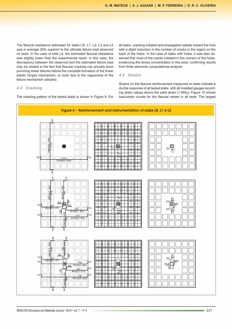
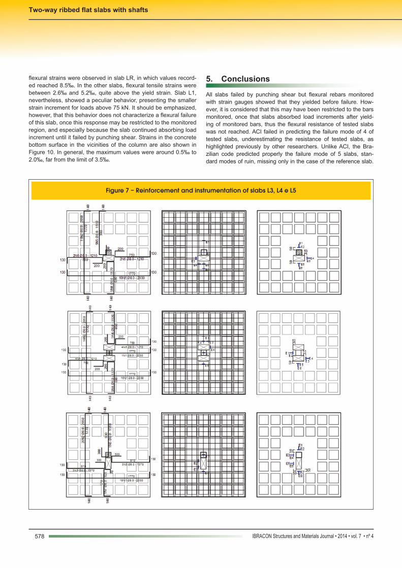
bers and the distance between the axes of the reaction rods was 1600 mm. Figure 5 shows the test system.Rebars were orthogonally placed near the top face of the slabs, with a concrete cover of 10 mm. The ends of the flexural reinforce-ment and of the rebars placed on the edges of the holes were hooked in order to guarantee their anchorage. Figures 6 and 7 sketches the flexural rebars and the position of strain gauges in steel and in the concrete surface of slabs LR, L1, L2, L3, L4 and L5, respectively. Strain gauges in the flexural rebars were posi-tioned tangentially to the column, while in the concrete surface
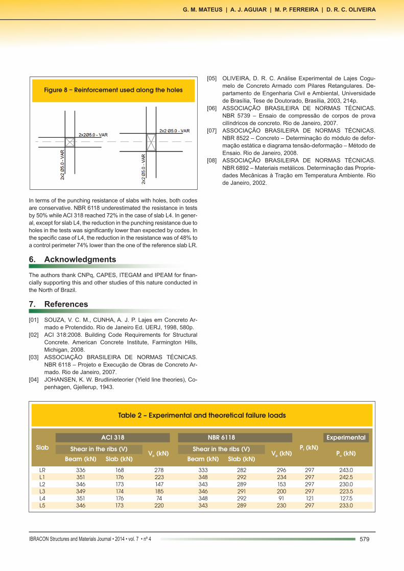
they were arranged in both orthogonal directions. Excel Sensores manufactured all gages used in this research. Figure 8 shows the reinforcement positioned on the edges of the holes, fulfilling the recommendations presented in Brazilian code.
4. Results
4.1 Materials (concrete and steel)
The mechanical properties of concrete were obtained with tests
Figure 3 – Dimensions of the slabs
Table 1 – Characteristics of tested slabs
Slab ρ (%) d (mm) f (MPa)c N° of holesDimensions of holes (mm)
LRL1L2L3L4L5
0.460.430.420.430.430.42
128134132133134132
x y
–120120240240120
–120120120120240
434343434343
–12121
576 IBRACON Structures and Materials Journal • 2014 • vol. 7 • nº 4
Two-way ribbed flat slabs with shafts
following the recommendations of the NBR 5739 (ABNT, 2007) [6] and NBR 8522 (ABNT, 2008) [7]. These tests were carried on the same day that the slabs were tested. Average results from tests on three concrete cylinders yielded results of 43 MPa for the com-pressive strength, 2.4 MPa for the tensile strength and 25.6 GPa for the modulus of elasticity. Tests for characterization of steel were based on the NBR 6892 (ABNT, 2002) [8], and the average results for 3 samples of 8 mm steel bars were of 553 MPa for the yield stress, corresponding to a strain of 1.95 ‰, and 284 GPa for the modulus of elasticity.
4.2 Failure load
Table 2 shows the experimental failure loads and those estimated theoretically using ACI 318 and NBR 6118. All tested slabs failed by punching after yielding of some of the flexural rebars. The shear resistance of the ribs was not a limitation, unlike predicted by ACI
318 treating them as slab. In this case, the ratio between the ex-perimental and the theoretical failure load by shear on the ribs were approximately 1.4, except for slab L4, which was 0.73. Al-though the codes agree in their estimates in terms of the one-way shear strength of the ribs (treated as beams), they diverge signifi-cantly if the resistance is checked as recommended for slabs, with the Brazilian codes results being around 67% higher than those estimated by ACI.In terms of the punching shear resistance, except for slab LR, all codes tended to underestimate the experimental results. This was more significant when slabs had two holes or one hole only, but largest than the column. For these cases, the length of the effec-tive control perimeter is smallest if compared to the length of the perimeter of a slab without holes. Reductions reached 72% (L4) for ACI 318 and 50% (L2) in NBR 6118 in the case of slabs with two holes. In the case of slabs with one hole only, reductions were up to 21% for ACI 318 and 12% for NBR 6118.
Figure 4 – Normative control perimeters for the tested slabs
Figure 5 – Test system
577IBRACON Structures and Materials Journal • 2014 • vol. 7 • nº 4
G. M. MATEUS | A. J. AGUIAR | M. P. FERREIRA | D. R. C. OLIVEIRA
The flexural resistance estimated for slabs LR, L1, L2, L3 and L5 was in average 25% superior to the ultimate failure load observed on tests. In the case of slab L4, the estimated flexural resistance was slightly lower than the experimental result. In this case, the discrepancy between the observed and the estimated failure load may be related to the fact that flexural cracking can actually favor punching shear failures before the complete formation of the linear plastic hinges mechanism, or even due to the vagueness of the failure mechanism adopted.
4.3 Cracking
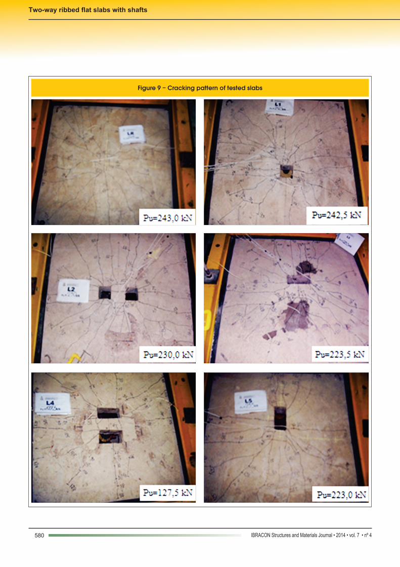
The cracking pattern of the tested slabs is shown in Figure 9. For
all slabs, cracking initiated and propagated radially toward the hole with a slight reduction in the number of cracks in the region on the back of the holes. In the case of slabs with holes, it was also ob-served that most of the cracks initiated in the corners of the holes, evidencing the stress concentration in this area, confirming results from finite elements computational analysis.
4.4 Strains
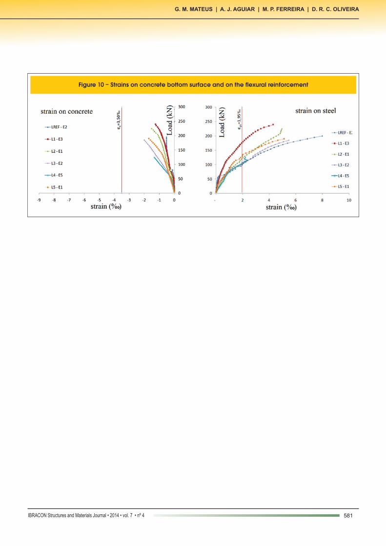
Strains on the flexural reinforcement measured on tests indicate a ductile response of all tested slabs, with all installed gauges record-ing strain values above the yield strain (1.95‰). Figure 10 shows load-strain curves for the flexural rebars in all tests. The largest
Figure 6 – Reinforcement and instrumentation of slabs LR, L1 e L2
578 IBRACON Structures and Materials Journal • 2014 • vol. 7 • nº 4
Two-way ribbed flat slabs with shafts
flexural strains were observed in slab LR, in which values record-ed reached 8.5‰. In the other slabs, flexural tensile strains were between 2.6‰ and 5.2‰, quite above the yield strain. Slab L1, nevertheless, showed a peculiar behavior, presenting the smaller strain increment for loads above 75 kN. It should be emphasized, however, that this behavior does not characterize a flexural failure of this slab, once this response may be restricted to the monitored region, and especially because the slab continued absorbing load increment until it failed by punching shear. Strains in the concrete bottom surface in the vicinities of the column are also shown in Figure 10. In general, the maximum values were around 0.5‰ to 2.0‰, far from the limit of 3.5‰.
5. Conclusions
All slabs failed by punching shear but flexural rebars monitored with strain gauges showed that they yielded before failure. How-ever, it is considered that this may have been restricted to the bars monitored, once that slabs absorbed load increments after yield-ing of monitored bars, thus the flexural resistance of tested slabs was not reached. ACI failed in predicting the failure mode of 4 of tested slabs, underestimating the resistance of tested slabs, as highlighted previously by other researchers. Unlike ACI, the Bra-zilian code predicted properly the failure mode of 5 slabs, stan-dard modes of ruin, missing only in the case of the reference slab.
Figure 7 – Reinforcement and instrumentation of slabs L3, L4 e L5
579IBRACON Structures and Materials Journal • 2014 • vol. 7 • nº 4
G. M. MATEUS | A. J. AGUIAR | M. P. FERREIRA | D. R. C. OLIVEIRA
In terms of the punching resistance of slabs with holes, both codes are conservative. NBR 6118 underestimated the resistance in tests by 50% while ACI 318 reached 72% in the case of slab L4. In gener-al, except for slab L4, the reduction in the punching resistance due to holes in the tests was significantly lower than expected by codes. In the specific case of L4, the reduction in the resistance was of 48% to a control perimeter 74% lower than the one of the reference slab LR.
6. Acknowledgments
The authors thank CNPq, CAPES, ITEGAM and IPEAM for finan-cially supporting this and other studies of this nature conducted in the North of Brazil.
7. References
[01] SOUZA, V. C. M., CUNHA, A. J. P. Lajes em Concreto Ar-mado e Protendido. Rio de Janeiro Ed. UERJ, 1998, 580p.
[02] ACI 318:2008. Building Code Requirements for Structural Concrete. American Concrete Institute, Farmington Hills, Michigan, 2008.
[03] ASSOCIAÇÃO BRASILEIRA DE NORMAS TÉCNICAS. NBR 6118 – Projeto e Execução de Obras de Concreto Ar-mado. Rio de Janeiro, 2007.
[04] JOHANSEN, K. W. Brudlinieteorier (Yield line theories), Co-penhagen, Gjellerup, 1943.
[05] OLIVEIRA, D. R. C. Análise Experimental de Lajes Cogu-melo de Concreto Armado com Pilares Retangulares. De-partamento de Engenharia Civil e Ambiental, Universidade de Brasília, Tese de Doutorado, Brasília, 2003, 214p.
[06] ASSOCIAÇÃO BRASILEIRA DE NORMAS TÉCNICAS. NBR 5739 – Ensaio de compressão de corpos de prova cilíndricos de concreto. Rio de Janeiro, 2007.
[07] ASSOCIAÇÃO BRASILEIRA DE NORMAS TÉCNICAS. NBR 8522 – Concreto – Determinação do módulo de defor-mação estática e diagrama tensão-deformação – Método de Ensaio. Rio de Janeiro, 2008.
[08] ASSOCIAÇÃO BRASILEIRA DE NORMAS TÉCNICAS. NBR 6892 – Materiais metálicos. Determinação das Proprie-dades Mecânicas à Tração em Temperatura Ambiente. Rio de Janeiro, 2002.
Figure 8 – Reinforcement used along the holes
Table 2 – Experimental and theoretical failure loads
SlabV (kN)p V (kN)p
P (kN)fP (kN)u
ACI 318 NBR 6118 Experimental
LRL1L2L3L4L5
27822314718574220
29623415320091230
297297297297121297
243.0242.5230.0223.5127.5233.0
Shear in the ribs (V) Shear in the ribs (V)
Beam (kN) Beam (kN)Slab (kN) Slab (kN)
336351346349351346
333348343346348343
168176173174176173
282292289291292289
580 IBRACON Structures and Materials Journal • 2014 • vol. 7 • nº 4
Two-way ribbed flat slabs with shafts
Figure 9 – Cracking pattern of tested slabs
581IBRACON Structures and Materials Journal • 2014 • vol. 7 • nº 4
G. M. MATEUS | A. J. AGUIAR | M. P. FERREIRA | D. R. C. OLIVEIRA
Figure 10 – Strains on concrete bottom surface and on the flexural reinforcement


![Two-way ribbed flat slabs with shafts - UFPArepositorio.ufpa.br/jspui/bitstream/2011/8158/2/Artigo... · 2018. 4. 13. · 318 (ACI, 2008) [2] and NBR 6118 (ABNT, 2007) [3]. Slabs](https://img.dokumen.tips/doc/110x75/60d42ea42ee9c464ad74d0de/two-way-ribbed-flat-slabs-with-shafts-2018-4-13-318-aci-2008-2-and-nbr.jpg)


![Shallow Flat Soffit Precast Concrete Floor SystemSimanjuntak [“System for joining precast concrete columns and slabs,” U.S. Patent No. 5,809,712 (1998)] developed a shallow- ribbed](https://img.dokumen.tips/doc/110x75/5f88d9d0c90a4847822d20d8/shallow-flat-sofit-precast-concrete-floor-system-simanjuntak-aoesystem-for-joining.jpg)