Embed Size (px)
Citation preview
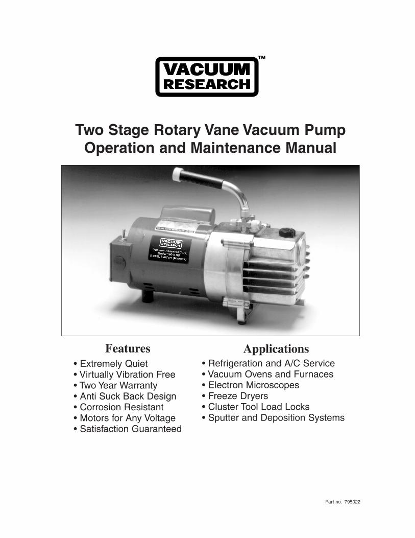
Two Stage Rotary Vane Vacuum PumpOperation and Maintenance Manual
Part no. 795022
™
Features• Extremely Quiet• Virtually Vibration Free• Two Year Warranty• Anti Suck Back Design• Corrosion Resistant• Motors for Any Voltage• Satisfaction Guaranteed
• Refrigeration and A/C Service• Vacuum Ovens and Furnaces• Electron Microscopes• Freeze Dryers• Cluster Tool Load Locks• Sputter and Deposition Systems
Applications
ContentsFORWARD....................................................................................................................................................1
WARNINGS..................................................................................................................................................2
PUMP SPECIFICATIONS AND PUMP SPEED CURVES.....................................................................3
DIMENSIONS..............................................................................................................................................3
PARTS LIST................................................................................................................................PAGES 4-5
EXPLODED VIEW DRAWING.................................................................................................................6
PREPARING AND INSTALLING THE PUMP........................................................................................8
RECEIVING....................................................................................................................................8
REPORTING SHIPPING SHORTAGE........................................................................................8
REPORTING INCORRECT SHIPMENT...................................................................................8
STARTING AND OPERATING THE PUMP............................................................................................9
START UP.........................................................................................................................................9
OPERATION....................................................................................................................................9
ANTISUCKBACK........................................................................................................................10
GAS BALLAST.............................................................................................................................10
MAINTAINING THE PUMP....................................................................................................................11
PREVENTATIVE MAINTENANCE..........................................................................................11
TROUBLESHOOTING...........................................................................................................12-13
May 2008

Forward
This manual contains installation, operation, maintenance, and troubleshooting information for the Model140-5 RS Rotary Vane Vacuum Pump.Please read it in its entirety before operating the pump.
Our Rotary Vane Vacuum Pumps are designed to ensure safety when used properly. It is the responsibilityof the user to follow safety-related warnings, cautions, notes, and other requirements described in thismanual.
Returned equipment will not be accepted by our company without prior authorization. Prior to shippingplease call for a returned goods authorization number (RGA).
Our company reserves the right to cancel the warranty if the pump is disassembled without authorization,if pump fluids are used that are not compatible with the design and materials used in the manufacture ofthe pump, and if unauthorized spare parts are used.
1
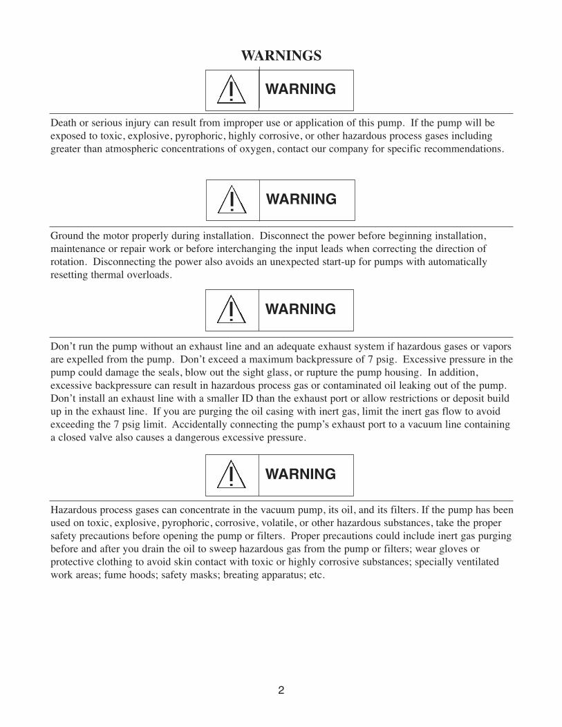
Death or serious injury can result from improper use or application of this pump. If the pump will beexposed to toxic, explosive, pyrophoric, highly corrosive, or other hazardous process gases includinggreater than atmospheric concentrations of oxygen, contact our company for specific recommendations.
WARNINGS
Ground the motor properly during installation. Disconnect the power before beginning installation,maintenance or repair work or before interchanging the input leads when correcting the direction ofrotation. Disconnecting the power also avoids an unexpected start-up for pumps with automaticallyresetting thermal overloads.
WARNING
Don’t run the pump without an exhaust line and an adequate exhaust system if hazardous gases or vaporsare expelled from the pump. Don’t exceed a maximum backpressure of 7 psig. Excessive pressure in thepump could damage the seals, blow out the sight glass, or rupture the pump housing. In addition,excessive backpressure can result in hazardous process gas or contaminated oil leaking out of the pump.Don’t install an exhaust line with a smaller ID than the exhaust port or allow restrictions or deposit buildup in the exhaust line. If you are purging the oil casing with inert gas, limit the inert gas flow to avoidexceeding the 7 psig limit. Accidentally connecting the pump’s exhaust port to a vacuum line containinga closed valve also causes a dangerous excessive pressure.
Hazardous process gases can concentrate in the vacuum pump, its oil, and its filters. If the pump has beenused on toxic, explosive, pyrophoric, corrosive, volatile, or other hazardous substances, take the propersafety precautions before opening the pump or filters. Proper precautions could include inert gas purgingbefore and after you drain the oil to sweep hazardous gas from the pump or filters; wear gloves or protective clothing to avoid skin contact with toxic or highly corrosive substances; specially ventilatedwork areas; fume hoods; safety masks; breating apparatus; etc.
2
WARNING
WARNING
WARNING
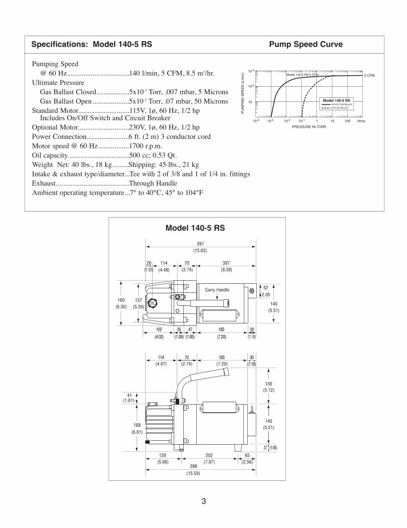
PRESSURE IN TORR
PU
MP
ING
SP
EE
D (
L/m
in)
10-4
10-3
10-2
10
10-3 10-2 10-1 1 10
5 CFM
100 Atmos.
Model 140-5 RSWITHOUT GAS BALLAST
WITH GAS BALLAST
Model 140-5 RS 5 CFM
Specifications: Model 140-5 RS Pump Speed Curve
(5.12)
(5.51)
(1.06)
130
140
27
(6.61)
168
41(1.61)
(6.30)
160
(5.39)
137
(5.51)
140
2.05
52
(4.48)(1.02) (2.74) (8.39)
(15.63)
397
397
Carry Handle
7026 114
(5.06) (7.97)
(15.59)
396(2.56)
129 202 65
(4.47) (2.74) (7.20) (1.18)
(1.18)(7.20)(1.85)(1.38)(4.02)
102
114 70 183 30
35 47 183 30
OIL
Pumping Speed @ 60 Hz..................................140 l/min, 5 CFM, 8.5 m3/hr.
Ultimate Pressure Gas Ballast Closed..................5x10-3 Torr, .007 mbar, 5 MicronsGas Ballast Open....................5x10-2 Torr, .07 mbar, 50 Microns
Standard Motor............................115V, 1ø, 60 Hz, 1/2 hp Includes On/Off Switch and Circuit Breaker
Optional Motor............................230V, 1ø, 60 Hz, 1/2 hpPower Connection.......................6 ft. (2 m) 3 conductor cordMotor speed @ 60 Hz.................1700 r.p.m.Oil capacity.................................. 500 cc; 0.53 Qt.Weight Net: 40 lbs., 18 kg.........Shipping: 45 lbs., 21 kg Intake & exhaust type/diameter...Tee with 2 of 3/8 and 1 of 1/4 in. fittingsExhaust........................................Through HandleAmbient operating temperature...7° to 40°C, 45° to 104°F
Model 140-5 RS
3
4
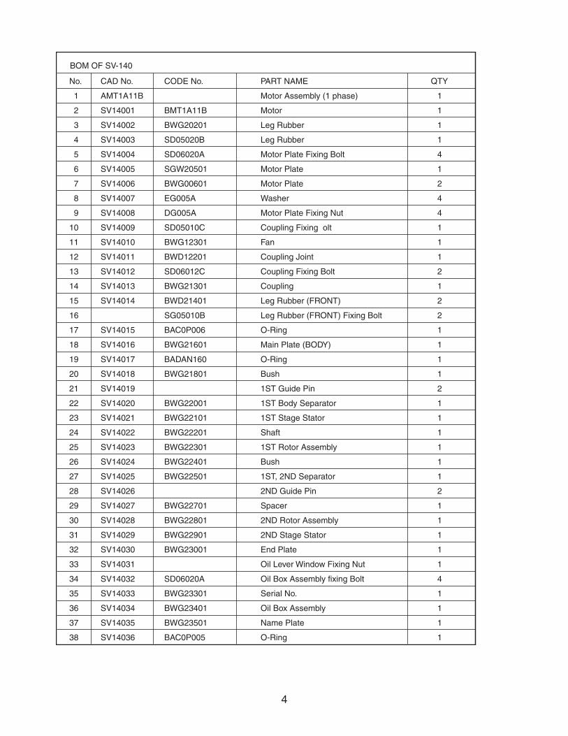
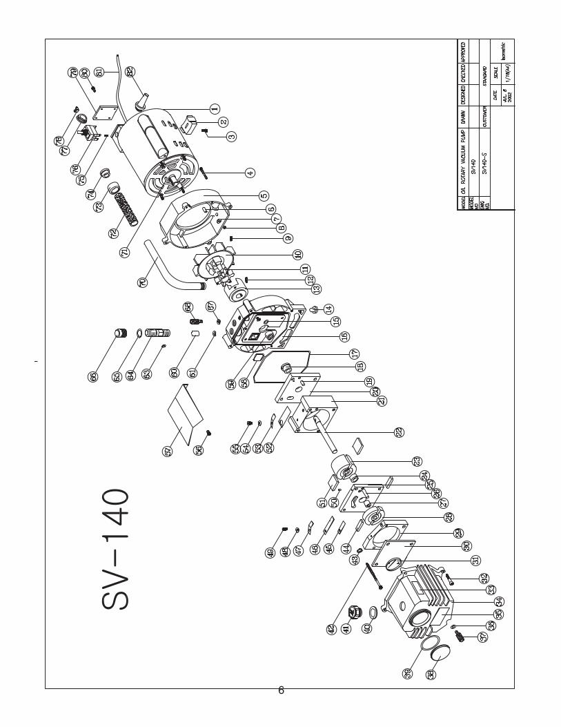
BOM OF SV-140
CAD No. CODE No. PART NAMENo.
AMT1A11B Motor Assembly (1 phase)1
SV14001 BMT1A11B Motor2
SV14002 BWG20201 Leg Rubber3
SV14003 SD05020B Leg Rubber4
SV14004 SD06020A Motor Plate Fixing Bolt5
SV14005 SGW20501 Motor Plate6
SV14006 BWG00601 Motor Plate7
SV14007 EG005A Washer8
SV14008 DG005A Motor Plate Fixing Nut9
SV14009 SD05010C Coupling Fixing olt10
SV14010 BWG12301 Fan11
SV14011 BWD12201 Coupling Joint12
SV14012 SD06012C Coupling Fixing Bolt13
SV14013 BWG21301 Coupling14
SV14014 BWD21401 Leg Rubber (FRONT)15
SG05010B Leg Rubber (FRONT) Fixing Bolt16
SV14015 BAC0P006 O-Ring17
SV14016 BWG21601 Main Plate (BODY)18
SV14017 BADAN160 O-Ring19
SV14018 BWG21801 Bush20
SV14019 1ST Guide Pin21
SV14020 BWG22001 1ST Body Separator22
SV14021 BWG22101 1ST Stage Stator23
SV14022 BWG22201 Shaft24
SV14023 BWG22301 1ST Rotor Assembly25
SV14024 BWG22401 Bush26
SV14025 BWG22501 1ST, 2ND Separator27
SV14026 2ND Guide Pin28
SV14027 BWG22701 Spacer29
SV14028 BWG22801 2ND Rotor Assembly30
SV14029 BWG22901 2ND Stage Stator31
SV14030 BWG23001 End Plate32
SV14031 Oil Lever Window Fixing Nut33
SV14032 SD06020A Oil Box Assembly fixing Bolt34
SV14033 BWG23301 Serial No.35
SV14034 BWG23401 Oil Box Assembly36
SV14035 BWG23501 Name Plate37
SV14036 BAC0P005 O-Ring
QTY
1
1
1
1
4
1
2
4
4
1
1
1
2
1
2
2
1
1
1
1
2
1
1
1
1
1
1
2
1
1
1
1
1
4
1
1
1
138
5
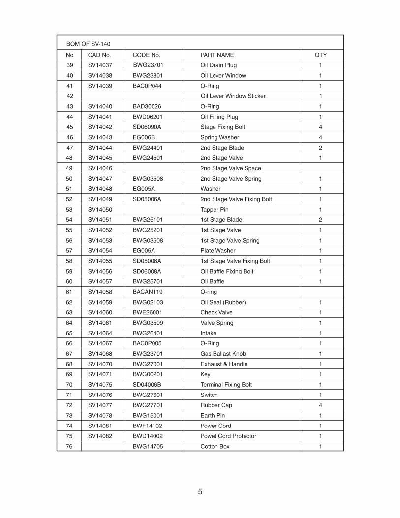
BOM OF SV-140
CAD No. CODE No. PART NAME QTYNo.
SV14037 Oil Drain Plug 139
SV14038 BWG23801 Oil Lever Window 140
SV14039 BAC0P044 O-Ring 141
Oil Lever Window Sticker 142
SV14040 BAD30026 O-Ring 143
SV14041 BWD06201 Oil Filling Plug 144
SV14042 SD06090A Stage Fixing Bolt 445
SV14043 EG006B Spring Washer 446
SV14044 BWG24401 2nd Stage Blade 247
SV14045 BWG24501 2nd Stage Valve 148
SV14046 2nd Stage Valve Space49
SV14047 BWG03508 2nd Stage Valve Spring 150
SV14048 EG005A Washer 151
SV14049 SD05006A 2nd Stage Valve Fixing Bolt 152
SV14050 Tapper Pin 153
SV14051 BWG25101 1st Stage Blade 254
SV14052 BWG25201 1st Stage Valve 155
SV14053 BWG03508 1st Stage Valve Spring 156
SV14054 EG005A Plate Washer 157
SV14055 SD05006A 1st Stage Valve Fixing Bolt 158
SV14056 SD06008A Oil Baffle Fixing Bolt 159
SV14057 BWG25701 Oil Baffle 160
SV14058 BACAN119 O-ring61
SV14059 BWG02103 Oil Seal (Rubber) 162
SV14060 BWE26001 Check Valve 163
SV14061 BWG03509 Valve Spring 164
SV14064 BWG26401 Intake 165
SV14067 BAC0P005 O-Ring 166
SV14068 BWG23701 Gas Ballast Knob 167
SV14070 BWG27001 Exhaust & Handle 168
SV14071 BWG00201 Key 169
SV14075 SD04006B Terminal Fixing Bolt 170
SV14076 BWG27601 Switch 171
SV14077 BWG27701 Rubber Cap 472
SV14078 BWG15001 Earth Pin 173
SV14081 BWF14102 Power Cord 174
SV14082 BWD14002 Powet Cord Protector 175
BWG14705 Cotton Box 176
BWG23701
6

PREPARING AND INSTALLING THE PUMP
RECEIVING
Each Rotary Vane Vacuum Pump is inspected and carefully packed prior to shipment. Inspect itafter carefully unpacking it. In case of external damage, retain the shipping container and notifythe shipping agency and our company immediately. Because the packing materials are designedspecifically for this pump, they should always be used when transporting the pump.
Unpack the pump and check for shipping damage as follows:
1. Inspect the outside of the shipping container for shipping damage. If you will be making a damage claim, save the shipping container and packing materials.
2. Unpack the pump.
3. Carefully inspect the pump for damage.
4. If you find any damage, proceed as follows:a. Save the shipping container, packing material, and parts for inspection.
b. Notify the carrier that made the delivery within 7 days of delivery.
c. File a claim with the carrier.
d. Contact our company to make arrangements for replacing the damaged part(s).
REPORTING SHIPPING SHORTAGE
If you did not receive all the goods that you ordered, do the following:1. Check the number of items listed on the packing slip. If the number of pieces listed is greaterthan the number of shipping containers received, contact the carrier concerning the missing piece.
2. Check the packing list to see if the missing item is on back order.
3. Carefully check the packing material and container to ensure that you did not overlookthe missing item.
4. If you cannot find the item, please notify our company immediately.
REPORTING INCORRECT SHIPMENT
If the item received is not the item ordered, contact our company immediately.
8
9
STARTING AND OPERATING THE PUMP
START UP
Before starting the pump, please complete the following checklist:
1. Be sure that the pump is filled with the appropriate amount of vacuum fluid.
2. Be sure that all electrical connections have been properly wired and that there are no bare wires that could cause an electrical shock or fire.
3. Be sure that all system connections have been secured with the appropriate seal rings and clamps.
4. Charge the pump with fluid as follows:
a. Reinstall the fluid-drain plug with flat gasket into the fluid-drain port.
b. Remove the fluid-fill cap and fill the pump to capacity with VPO-3000 vacuum pumpfluid. Using other than VPO-3000 vacuum pump fluid may result in damage to thepump or compromise the pump performance and lifetime.
c. Reinstall the fluid-fill cap with flat gasket.
Long Term Storage (2 weeks or longer)
Before placing a pump in long term storage, follow the procedure below:
1. Drain all fluids from the pump as described in the previous section.
2. Refill the pump with clean VPO-3000 vacuum fluid as described in section for changing the pump fluid.
3. Be sure that the pump is stored in a horizontal position with the intake and exhaust ports facing up.
5. When putting a pump into storage, put a pin hole in both the intake and exhaust port caps.
Avoiding Oil Leaks During Shipping and Storage
Always drain your vacuum pump of all fluids before shipping. Failure to do so can result indamaged shipping containers and delays by freight carriers due to possibility of the presenceof hazardous materials in the event of a spill.
10
OPERATION
1. Periodically check the vacuum fluid level in the sight glass to be sure it is between the low and high levels. If you are operating the pump with the gas ballast open, it will be necessary to check the oil level more frequently.
2. If the vacuum fluid within the pump becomes discolored or contaminated, change the fluid as soon as possible. Operating the pump with contaminated or dirty oil will greatly reduce the life expectancy of the pump and may lead to the cancellation of the warranty.
ANTI SUCK BACK
If the pump stops with the inlet under vacuum the anti suck back system will stop air or oilleakage inside the module or into the vacuum chamber. The vacuum integrity is guaranteed by:
• Quality of machining from surfaces between the functional elements (stator, plates, housing,etc.)
• The exhaust valves on the exhaust orifice.
• A spring valve automatically closes the oil injection canal in the pump. When the pump stops, the oil pump exhaust pressure is decreased and a spring activated valve closes the oil injection canal.
GAS BALLAST
When condensable vapors (such as water vapor) are being pumped the gas is compressedbeyond its saturated pressure and can condense, impairing pump performance. The vapor pres-sure of water at typical pump temperatures is over 100 Torr. Even small amounts of water inthe pump fluid will have a big effect on pump performance. The gas ballast control buttonallows a quantity of air to be injected into the second stage of the pump during “compression”to reduce the partial pressure of the pumped gas below its saturated vapor pressure and thusprevent condensation.At the end of “compression” the pressure in the discharge chamber is greater than atmospheric.The antisuckback feature described above prevents gas and oil from being discharged into theenvironment.The saturated vapor pressure of pump fluid and the condensed vapors such as water is higherwhen it is hot than when it is cold; therefore it is necessary to wait until the pump reaches itsoperating temperature before pumping condensable vapor. Using the gas ballast increases theultimate pressure of the pump as well as its operating temperature.
11
MAINTAINING THE PUMP
PREVENTIVE MAINTENANCE
Pump Fluid
Every vacuum pump is designed to work best with a specific pump fluid and the fluid is anactive part of the pumping mechanism. For best performance from your pump, care must beused to select fluid with the physical and chemical properties engineered for your pump. Forour pumps the ideal fluid for general purpose pumping is VPO-3000. This is a moderatelypriced fluid that is engineered to give best vacuum and longest life in our pumps. Other fluidsmay give performance that is good enough for your needs but our specifications are based onregular use of VPO-3000.
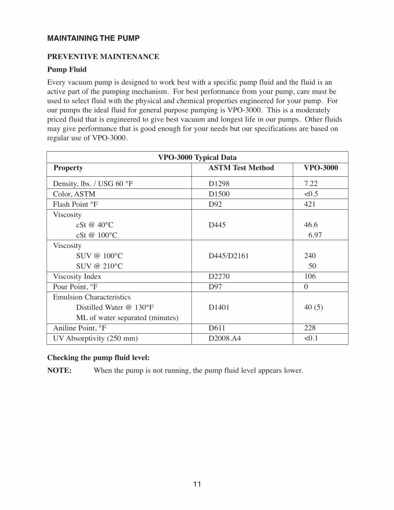
VPO-3000 Typical DataProperty ASTM Test Method VPO-3000
Density, lbs. / USG 60 °FColor, ASTMFlash Point °FViscosity
cSt @ 40°CcSt @ 100°C
ViscositySUV @ 100°CSUV @ 210°C
Viscosity IndexPour Point, °FEmulsion Characteristics
Distilled Water @ 130°FML of water separated (minutes)
Aniline Point, °FUV Absorptivity (250 mm)
D1298D1500D92
D445
D445/D2161
D2270D97
D1401
D611D2008.A4
7.22<0.5421
46.66.97
24050
1060
40 (5)
228<0.1
Checking the pump fluid level:
NOTE: When the pump is not running, the pump fluid level appears lower.
12
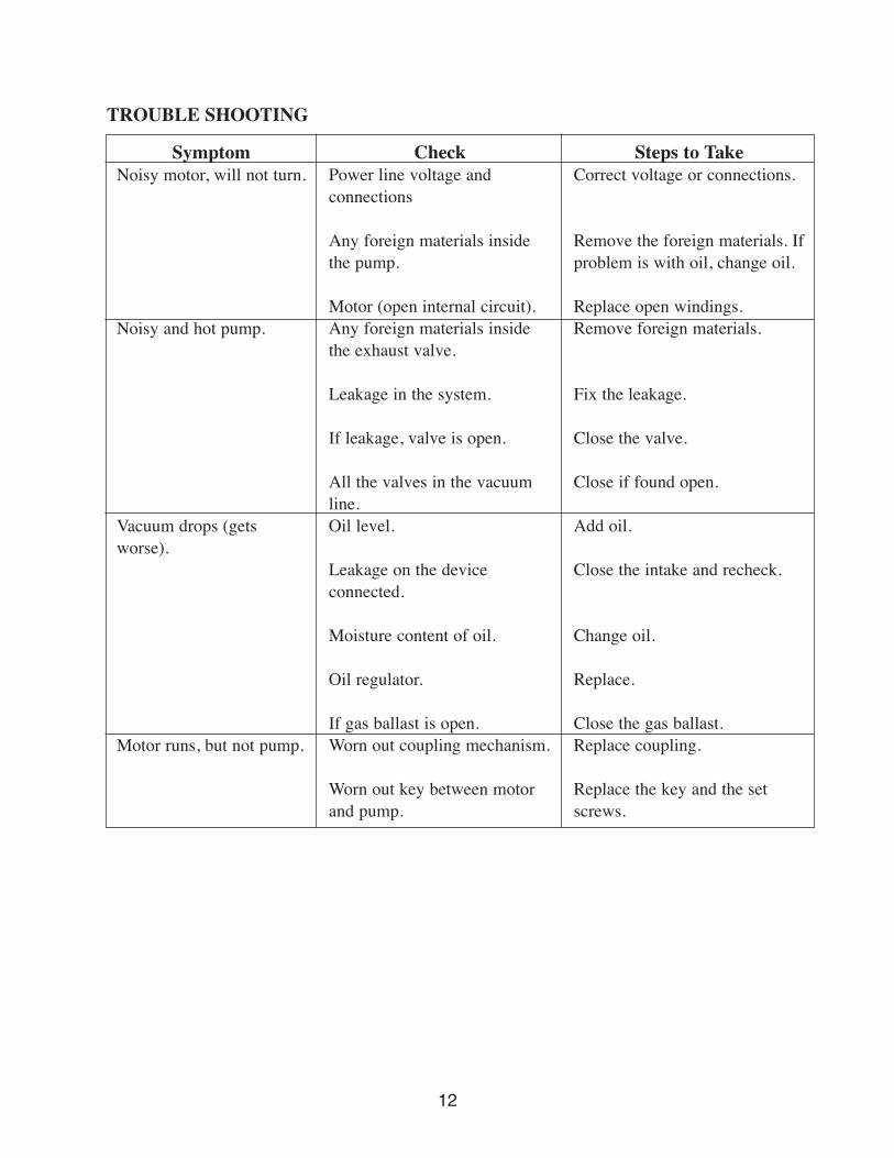
CheckPower line voltage andconnections
Any foreign materials inside the pump.
Motor (open internal circuit).Any foreign materials insidethe exhaust valve.
Leakage in the system.
If leakage, valve is open.
All the valves in the vacuumline.Oil level.
Leakage on the device connected.
Moisture content of oil.
Oil regulator.
If gas ballast is open.Worn out coupling mechanism.
Worn out key between motorand pump.
TROUBLE SHOOTING
SymptomNoisy motor, will not turn.
Noisy and hot pump.
Vacuum drops (getsworse).
Motor runs, but not pump.
Steps to TakeCorrect voltage or connections.
Remove the foreign materials. Ifproblem is with oil, change oil.
Replace open windings.Remove foreign materials.
Fix the leakage.
Close the valve.
Close if found open.
Add oil.
Close the intake and recheck.
Change oil.
Replace.
Close the gas ballast.Replace coupling.
Replace the key and the setscrews.
CAUTION: Hydrocarbon pump fluid should be changed at the following times:
1. After a 100 hour break-in period of pump operation.
2. When the pump fluid becomes contaminated.
3. When condensation in the pump fluid is present.
4. Before and after the pump has been stored for a long period of time.
NOTE: Always change the pump fluid while the pump is warm to prevent condensables,such as water, from remaining in the pump.
Turn the pump off and change the fluid as follows:
1. Drain the fluid from the pump. Use your fingers to remove the oil fill cap and the oildrain plug from the pump; allow the fluid to drain into a suitable container. If the fluidfill cap or fluid drain cap cannot be loosened with your fingers, cover them with a clothand use pliers.
2. After the oil flow dimininshes, switch ON the pump, allow it to run for about 10 secondsand then switch it OFF.
3. If the fluid drained from the pump is discolored, contains particulate, has a foul odor oris very dirty, flush out the pump using the procedure below until the drained fluid isclean. If your pump requires more than 2 flushes, a foreline trap or oil filtration unitshould be installed on the pump. Contact our company for more information on foreline traps and oil filtration units.
a. Reinstall the fluid-drain plug with flat gasket into the fluid-drain port.
b. Refill the pump with VPO-3000 vacuum pump fluid until the fluid level is visible in the lower rim of the fluid sight glass.
c. Reinstall the fluid-fill plug with gasket in the fluid fill port.
d. Turn ON the pump and allow it to run for about 10 minutes.
e. Turn the pump OFF and refer to step 1 to drain the vacuum fluid.
13

Vacuum Research Corp. • 2419 Smallman Street • Pittsburgh, PA 15222 USA • www.vacuumresearch.comPhone: 800-426-9340 • 412-261-7630 • FAX: 412-261-7220 • e-mail: [email protected]