Embed Size (px)
Citation preview
TS0040UK00
RLS SERIES RLS 28 100/163 ÷ 325 kWRLS 38 116/232 ÷ 442 kWRLS 50 145/290 ÷ 581 kWRLS 70 232/465 ÷ 814 kWRLS 100 349/698 ÷ 1163 kWRLS 130 465/930 ÷ 1395 kW
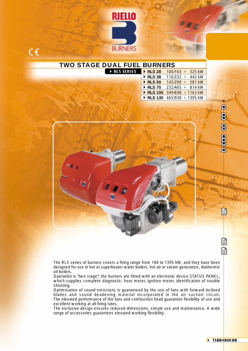
TWO STAGE DUAL FUEL BURNERS
The RLS series of burners covers a firing range from 100 to 1395 kW, and they have beendesigned for use in hot or superheater water boilers, hot air or steam generators, diathermicoil boilers.Operation is "two stage"; the burners are fitted with an electronic device STATUS PANEL,which supplies complete diagnostic: hour meter, ignition meter, identification of troubleshooting.Optimisation of sound emissions is guaranteed by the use of fans with forward inclinedblades and sound deadening material incorporated in the air suction circuit.The elevated performance of the fans and combustion head guarantee flexibility of use andexcellent working at all firing rates.The exclusive design ensures reduced dimensions, simple use and maintenance. A widerange of accessories guarantees elevated working flexibility.
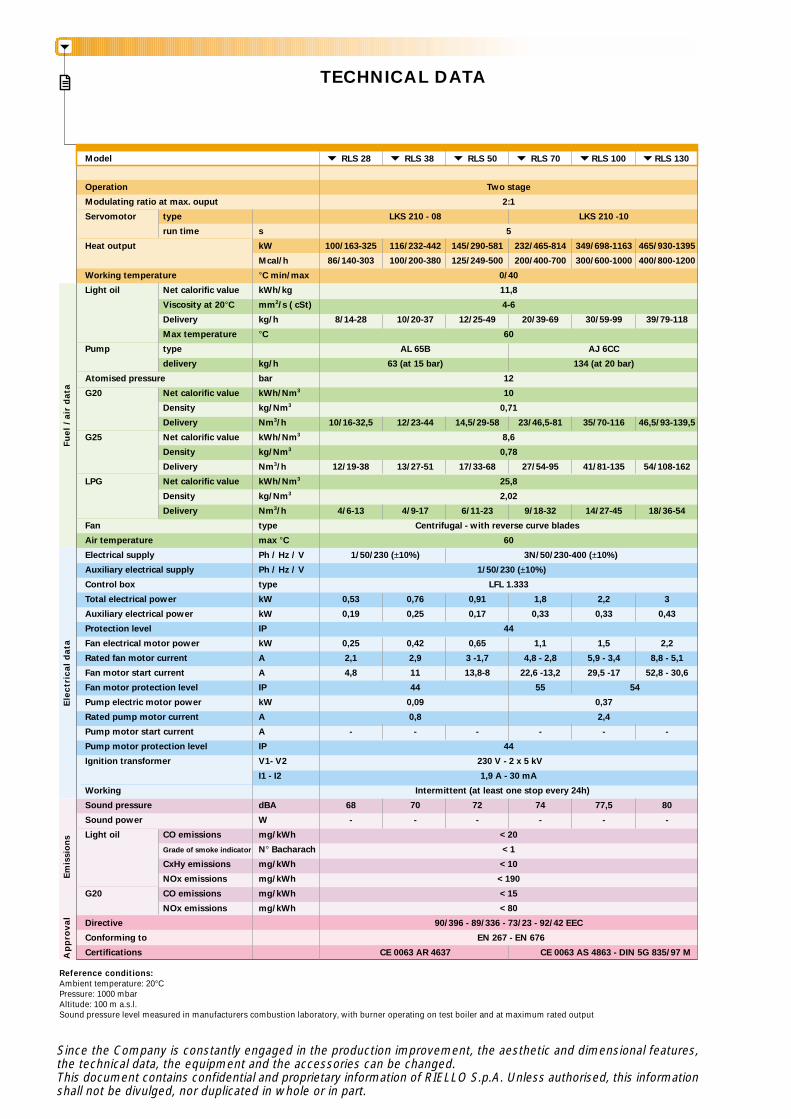
TECHNICAL DATA
Model RLS 28 RLS 70
Ap
pro
val
Fuel
/ ai
r d
ata
Ele
ctri
cal d
ata
Em
issi
ons
RLS 38 RLS 50 RLS 130RLS 100
Since the Company is constantly engaged in the production improvement, the aesthetic and dimensional features,the technical data, the equipment and the accessories can be changed.This document contains confidential and proprietary information of RIELLO S.p.A. Unless authorised, this informationshall not be divulged, nor duplicated in whole or in part.
Reference conditions:Ambient temperature: 20°CPressure: 1000 mbarAltitude: 100 m a.s.l.Sound pressure level measured in manufacturers combustion laboratory, with burner operating on test boiler and at maximum rated output
Operation Two stage
Modulating ratio at max. ouput 2:1
Servomotor type LKS 210 - 08 LKS 210 -10
run time s 5
Heat output kW 100/163-325 116/232-442 145/290-581 232/465-814 349/698-1163 465/930-1395
Mcal/h 86/140-303 100/200-380 125/249-500 200/400-700 300/600-1000 400/800-1200
Working temperature °C min/max 0/40
Light oil Net calorific value kWh/kg 11,8
Viscosity at 20°C mm2/s ( cSt) 4-6
Delivery kg/h 8/14-28 10/20-37 12/25-49 20/39-69 30/59-99 39/79-118
Max temperature °C 60
Pump type AL 65B AJ 6CC
delivery kg/h 63 (at 15 bar) 134 (at 20 bar)
Atomised pressure bar 12
G20 Net calorific value kWh/Nm3 10
Density kg/Nm3 0,71
Delivery Nm3/h 10/16-32,5 12/23-44 14,5/29-58 23/46,5-81 35/70-116 46,5/93-139,5
G25 Net calorific value kWh/Nm3 8,6
Density kg/Nm3 0,78
Delivery Nm3/h 12/19-38 13/27-51 17/33-68 27/54-95 41/81-135 54/108-162
LPG Net calorific value kWh/Nm3 25,8
Density kg/Nm3 2,02
Delivery Nm3/h 4/6-13 4/9-17 6/11-23 9/18-32 14/27-45 18/36-54
Fan type Centrifugal - with reverse curve blades
Air temperature max °C 60
Electrical supply Ph / Hz / V 1/50/230 (±10%) 3N/50/230-400 (±10%)
Auxiliary electrical supply Ph / Hz / V 1/50/230 (±10%)
Control box type LFL 1.333
Total electrical power kW 0,53 0,76 0,91 1,8 2,2 3
Auxiliary electrical power kW 0,19 0,25 0,17 0,33 0,33 0,43
Protection level IP 44
Fan electrical motor power kW 0,25 0,42 0,65 1,1 1,5 2,2
Rated fan motor current A 2,1 2,9 3 -1,7 4,8 - 2,8 5,9 - 3,4 8,8 - 5,1
Fan motor start current A 4,8 11 13,8-8 22,6 -13,2 29,5 -17 52,8 - 30,6
Fan motor protection level IP 44 55 54
Pump electric motor power kW 0,09 0,37
Rated pump motor current A 0,8 2,4
Pump motor start current A - - - - - -
Pump motor protection level IP 44
Ignition transformer V1- V2 230 V - 2 x 5 kV
I1 - I2 1,9 A - 30 mA
Working Intermittent (at least one stop every 24h)
Sound pressure dBA 68 70 72 74 77,5 80
Sound power W - - - - - -
Light oil CO emissions mg/kWh < 20
Grade of smoke indicator N° Bacharach < 1
CxHy emissions mg/kWh < 10
NOx emissions mg/kWh < 190
G20 CO emissions mg/kWh < 15
NOx emissions mg/kWh < 80
Directive 90/396 - 89/336 - 73/23 - 92/42 EEC
Conforming to EN 267 - EN 676
Certifications CE 0063 AR 4637 CE 0063 AS 4863 - DIN 5G 835/97 M
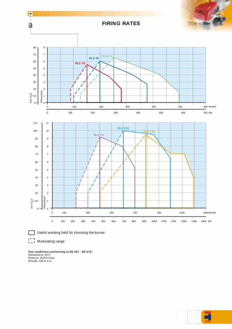
FIRING RATES
Test conditions conforming to EN 267 - EN 676:Temperature: 20°CPressure: 1013.5 mbarAltitude: 100 m a.s.l.
Useful working field for choosing the burner
Modulating range
0
2
4
6
5
3
1
7
8
100 kW200 300 400 500 600 700
0
0
0
20
40
60
50
30
10
70
80
RLS 28
RLS 38RLS 50
hP
a (m
bar
)
mm
H2O
Mcal/h500300100 600400200
0
2
4
6
5
3
1
7
9
8
10
11
100 kW200 300 400 500 600 700 800 900 1000 1100 1200 1300 1400 1500
0
0
0
20
40
60
50
30
10
70
90
80
100
110
RLS 130RLS 100
RLS 70
hP
a (m
bar
)
mm
H2O
500300100 700 900 1100 1300 Mcal/h
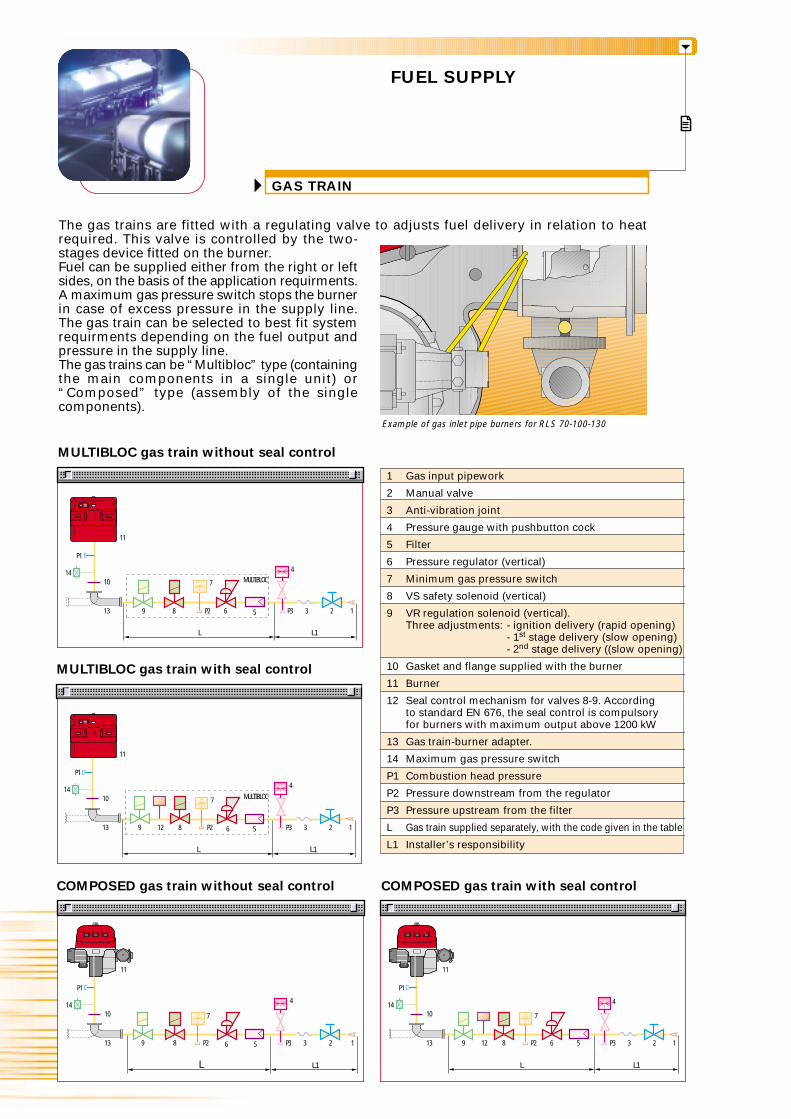
GAS TRAIN
FUEL SUPPLY
The gas trains are fitted with a regulating valve to adjusts fuel delivery in relation to heatrequired. This valve is controlled by the two-stages device fitted on the burner.Fuel can be supplied either from the right or leftsides, on the basis of the application requirments.A maximum gas pressure switch stops the burnerin case of excess pressure in the supply line.The gas train can be selected to best fit systemrequirments depending on the fuel output andpressure in the supply line.The gas trains can be “Multibloc” type (containingthe main components in a single unit) or“Composed” type (assembly of the singlecomponents).
Example of gas inlet pipe burners for RLS 70-100-130
COMPOSED gas train without seal control
9 8 3
COMPOSED gas train with seal control
9 8
MULTIBLOC gas train without seal control
L L1
MULTIBLOC
MULTIBLOC gas train with seal control
9 8
L L1
MULTIBLOC
L L1
P1
1014
13 2 1
11
P2
7
6 5 P3
4
L L1
P1
1014
13 P3
4
3 2 112
11
56P2
7
11
P1
1014
13 9 8 P2 6 P3
4
3 2 15
P1
1014
13 P3
4
3 2 112
11
56P2
7
7
Gas input pipework
Manual valve
Anti-vibration joint
Pressure gauge with pushbutton cock
Filter
Pressure regulator (vertical)
Minimum gas pressure switch
VS safety solenoid (vertical)
VR regulation solenoid (vertical).Three adjustments: - ignition delivery (rapid opening)
- 1st stage delivery (slow opening)- 2nd stage delivery ((slow opening)
Gasket and flange supplied with the burner
Burner
Seal control mechanism for valves 8-9. Accordingto standard EN 676, the seal control is compulsoryfor burners with maximum output above 1200 kW
Gas train-burner adapter.
Maximum gas pressure switch
Combustion head pressure
Pressure downstream from the regulator
Pressure upstream from the filter
Gas train supplied separately, with the code given in the table
Installer’s responsibility
1
2
3
4
5
6
7
8
9
10
11
12
13
14
P1
P2
P3
L
L1
MU
LTIB
LOC
GA
S T
RA
INS
CO
MP
OS
ED
GA
S T
RA
INS
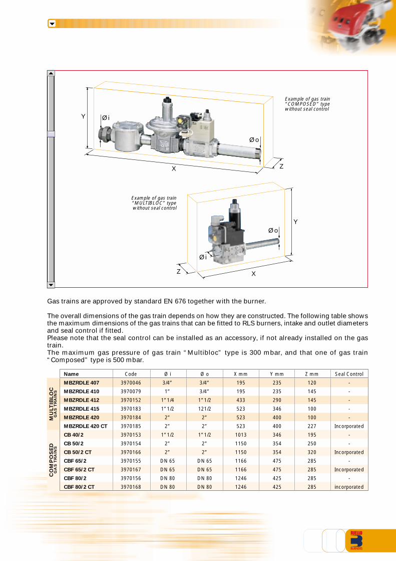
Gas trains are approved by standard EN 676 together with the burner.
The overall dimensions of the gas train depends on how they are constructed. The following table showsthe maximum dimensions of the gas trains that can be fitted to RLS burners, intake and outlet diametersand seal control if fitted.Please note that the seal control can be installed as an accessory, if not already installed on the gastrain.The maximum gas pressure of gas train “Multibloc” type is 300 mbar, and that one of gas train“Composed” type is 500 mbar.
Y
ZX
Øi
Øo
Example of gas train“COMPOSED” typewithout seal control
Y
Z X
Øi
Øo
Example of gas train“MULTIBLOC” typewithout seal control
Name Code Ø i Ø o X mm Y mm Z mm Seal Control
MBZRDLE 407 3970046 3/4” 3/4” 195 235 120 -
MBZRDLE 410 3970079 1” 3/4” 195 235 145 -
MBZRDLE 412 3970152 1”1/4 1”1/2 433 290 145 -
MBZRDLE 415 3970183 1”1/2 121/2 523 346 100 -
MBZRDLE 420 3970184 2” 2” 523 400 100 -
MBZRDLE 420 CT 3970185 2” 2” 523 400 227 Incorporated
CB 40/2 3970153 1”1/2 1”1/2 1013 346 195 -
CB 50/2 3970154 2” 2” 1150 354 250 -
CB 50/2 CT 3970166 2” 2” 1150 354 320 Incorporated
CBF 65/2 3970155 DN 65 DN 65 1166 475 285 -
CBF 65/2 CT 3970167 DN 65 DN 65 1166 475 285 Incorporated
CBF 80/2 3970156 DN 80 DN 80 1246 425 285 -
CBF 80/2 CT 3970168 DN 80 DN 80 1246 425 285 incorporated
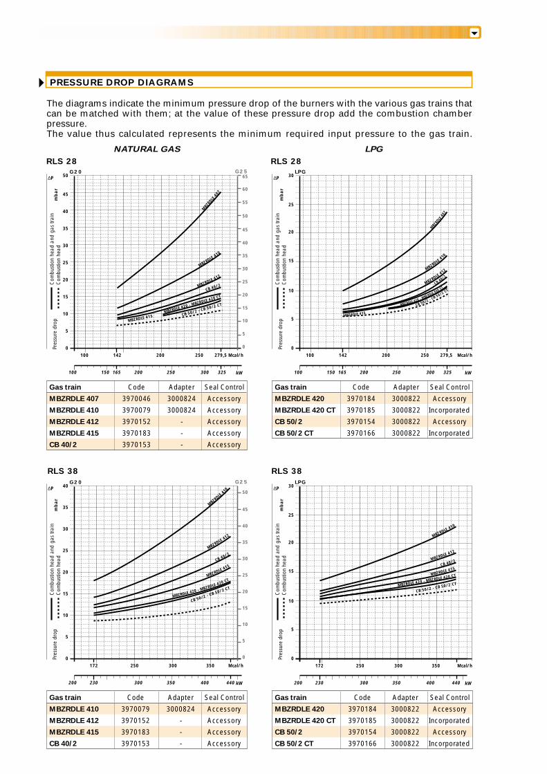
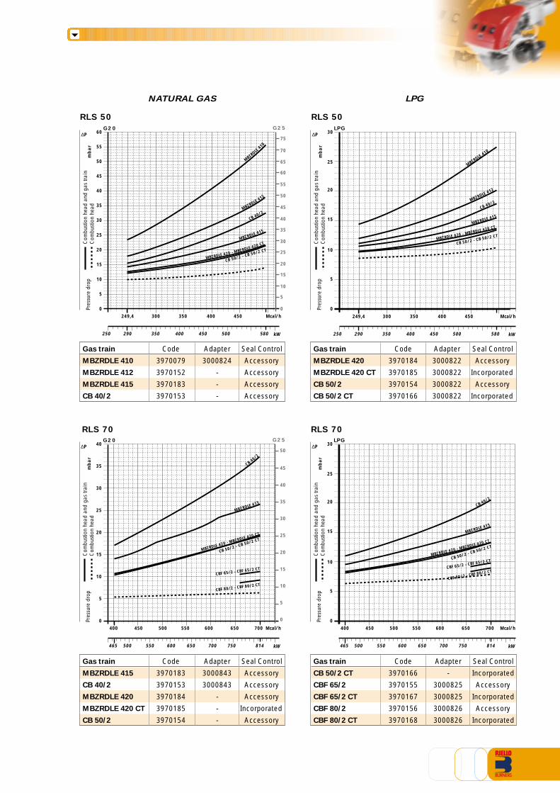
The diagrams indicate the minimum pressure drop of the burners with the various gas trains thatcan be matched with them; at the value of these pressure drop add the combustion chamberpressure.The value thus calculated represents the minimum required input pressure to the gas train.
NATURAL GAS LPG
RLS 28 RLS 28
RLS 38 RLS 38
PRESSURE DROP DIAGRAMS
MBZRDLE 415 CB 50/2 - CB 50/2 CT
CB 50/2 - CB 50/2 CTCB 50/2 - CB 50/2 CT
Mcal/h
5
10
15
0100 142 250
mb
ar
G25G20
0
15
10
5
20
20 25
kW200100 150 250 300
200
25
30
35
40
35
30
45
4050
45
50 65
60
55MBZ
RDLE
407
LPG
MBZRDLE410
MBZRDLE 412
MBZRDLE 420 - MBZRDLE 420 CT
CB 40/2
325165
279,5 Mcal/h
5
10
15
0100 142 250
mb
ar
20
kW200100 150 250 300
200
25
30
MBZRD
LE40
7
MBZRDLE410
MBZRDLE412
MBZRDLE 415
MBZRDLE 420 - MBZRDLE 420 CTCB 40/2
325165
279,5
Mcal/h
5
10
15
0172 350
mb
ar
G25G20
0
15
10
5
20
20 25
kW300200 350 400
300
25
30
35
40
35
30
45
5040
LPG
MBZRD
LE41
0
MBZRDLE412
MBZRDLE 415
440230
5
10
15
0
mb
ar
20
25
30∆P
Com
busti
on h
ead
and
gas
train
Com
busti
on h
ead
Pres
sure
dro
p
250
MBZRDLE 420 - MBZRDLE 420 CT
CB 40/2
kW300200 350 400 440230
Mcal/h172 350300250
MBZRDLE 410
MBZRDLE 412
MBZRDLE 415
MBZRDLE 420 - MBZRDLE 420 CT
CB 40/2
CB 50/2 - CB 50/2 CT
∆P
Com
busti
on h
ead
and
gas
train
Com
busti
on h
ead
Pres
sure
dro
p
∆P
Com
busti
on h
ead
and
gas
train
Com
busti
on h
ead
Pres
sure
dro
p
∆P
Com
busti
on h
ead
and
gas
train
Com
busti
on h
ead
Pres
sure
dro
p
Gas train Code Adapter Seal Control
MBZRDLE 407 3970046 3000824 Accessory
MBZRDLE 410 3970079 3000824 Accessory
MBZRDLE 412 3970152 - Accessory
MBZRDLE 415 3970183 - Accessory
CB 40/2 3970153 - Accessory
Gas train Code Adapter Seal Control
MBZRDLE 420 3970184 3000822 Accessory
MBZRDLE 420 CT 3970185 3000822 Incorporated
CB 50/2 3970154 3000822 Accessory
CB 50/2 CT 3970166 3000822 Incorporated
Gas train Code Adapter Seal Control
MBZRDLE 410 3970079 3000824 Accessory
MBZRDLE 412 3970152 - Accessory
MBZRDLE 415 3970183 - Accessory
CB 40/2 3970153 - Accessory
Gas train Code Adapter Seal Control
MBZRDLE 420 3970184 3000822 Accessory
MBZRDLE 420 CT 3970185 3000822 Incorporated
CB 50/2 3970154 3000822 Accessory
CB 50/2 CT 3970166 3000822 Incorporated
NATURAL GAS LPG
RLS 50 RLS 50
RLS 70 RLS 70
CB 50/2 - CB 50/2 CT
CB 50/2 - CB 50/2 CT
kW290250 350 400 450 500 580
CB 50/2 - CB 50/2 CT
CB 50/2 - CB 50/2 CT
Mcal/h
5
10
15
0350
mb
ar
G25G20
0
15
10
5
20
20 25
400
25
30
35
40
35
30
45
7560
LPG
MBZRD
LE41
0
MBZRDLE 412
MBZRDLE 415
5
10
15
0
mb
ar
20
25
30∆P
Com
busti
on h
ead
and
gas
train
Com
busti
on h
ead
Pres
sure
dro
p
300
MBZRDLE 420 - MBZRDLE 420 CT
CB 40/2
MBZRDLE410
MBZRDLE 412
MBZRDLE 415
MBZRDLE 420 - MBZRDLE 420 CT
CB 40/2
249,4 450
40
55
45
50
70
65
60
55
50
Mcal/h350 400300249,4 450
kW290250 350 400 450 500 580
Mcal/h
5
10
15
0400 700
mb
ar
G25G20
0
15
10
5
20
20 25
600
25
30
35
40
35
30
45
5040
LPG
MBZRDLE 415
5
10
15
0
mb
ar
20
25
30∆P
Com
busti
on h
ead
and
gas
train
Com
busti
on h
ead
Pres
sure
dro
p
450
MBZRDLE 420 - MBZRDLE 420 CT
CB 40/2
500 650550
CBF 65/2 - CBF 65/2 CT
CBF 80/2 - CBF 80/2 CT
Mcal/h400 700600450 500 650550
kW650465 700 814500 550 600 750
MBZRDLE 415
MBZRDLE 420 - MBZRDLE 420 CT
CB 40/2
CBF 65/2 - CBF 65/2 CT
CBF 80/2 - CBF 80/2 CT
∆P
Com
busti
on h
ead
and
gas
train
Com
busti
on h
ead
Pres
sure
dro
p
∆P
Com
busti
on h
ead
and
gas
train
Com
busti
on h
ead
Pres
sure
dro
p
Gas train Code Adapter Seal Control
MBZRDLE 410 3970079 3000824 Accessory
MBZRDLE 412 3970152 - Accessory
MBZRDLE 415 3970183 - Accessory
CB 40/2 3970153 - Accessory
Gas train Code Adapter Seal Control
MBZRDLE 420 3970184 3000822 Accessory
MBZRDLE 420 CT 3970185 3000822 Incorporated
CB 50/2 3970154 3000822 Accessory
CB 50/2 CT 3970166 3000822 Incorporated
Gas train Code Adapter Seal Control
MBZRDLE 415 3970183 3000843 Accessory
CB 40/2 3970153 3000843 Accessory
MBZRDLE 420 3970184 - Accessory
MBZRDLE 420 CT 3970185 - Incorporated
CB 50/2 3970154 - Accessory
Gas train Code Adapter Seal Control
CB 50/2 CT 3970166 - Incorporated
CBF 65/2 3970155 3000825 Accessory
CBF 65/2 CT 3970167 3000825 Incorporated
CBF 80/2 3970156 3000826 Accessory
CBF 80/2 CT 3970168 3000826 Incorporated
kW650465 700 814500 550 600 750
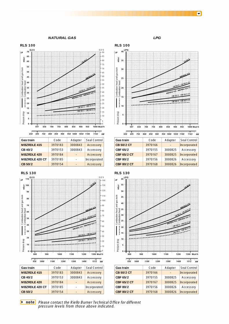
NATURAL GAS LPG
RLS 100 RLS 100
RLS 130 RLS 130
CB 50/2 - CB 50/2 CT
CB 50/2 - CB 50/2 CT
CB 50/2 - CB 50/2 CT
CB 50/2 - CB 50/2 CT
Mcal/h
5
10
15
0750
mb
ar
G25G20
0
15
10
5
20
20 25
850
25
30
35
40
35
30
45
75
60
LPG
MBZRDLE 415
5
10
15
0
mb
ar
20
25
40∆P
Com
busti
on h
ead
and
gas
train
Com
busti
on h
ead
Pres
sure
dro
p
1000
MBZRDLE 420 - MBZRDLE 420 CT
CB 40/2
900
40
55
45
50
70
65
60
55
50
Mcal/h
10
0800 1300
mb
ar
G25G20
0
60
50
40
70
20
80
1100
40
30
90
110
100
90
120
130
110LPG
MBZRDLE 415
10
20
30
0
mb
ar
35
50
60∆P
Com
busti
on h
ead
and
gas
train
Com
busti
on h
ead
Pres
sure
dro
p
900
MBZRDLE 420 - MBZRDLE 420 CT
CB 40/2
12001000
CBF 65/2 - CBF 65/2 CT
CBF 80/2 - CBF 80/2 CT
65
70
80
85
90
30
35
950800700650597
CBF 65/2 - CBF 65/2 CT
CBF 80/2 - CBF 80/2 CT
Mcal/h750 850
MBZRDLE 415
MBZRDLE 420 - MBZRDLE 420 CT
CB 40/2
900 950800700650597
CBF 65/2 - CBF 65/2 CT
CBF 80/2 - CBF 80/2 CT
1000
50
60
70
80
100
30
10
20
140
5
15
25
40
45
55
Mcal/h800 13001100900 12001000
kW930 1000 1100 1200 1300 1400 1512
MBZRDLE 415
MBZRDLE 420 - MBZRDLE 420 CT
CB 40/2
CBF 65/2 - CBF 65/2 CT
CBF 80/2 - CBF 80/2 CT
∆P
Com
busti
on h
ead
and
gas
train
Com
busti
on h
ead
Pres
sure
dro
p
∆P
Com
busti
on h
ead
and
gas
train
Com
busti
on h
ead
Pres
sure
dro
p
Gas train Code Adapter Seal Control
MBZRDLE 415 3970183 3000843 Accessory
CB 40/2 3970153 3000843 Accessory
MBZRDLE 420 3970184 - Accessory
MBZRDLE 420 CT 3970185 - Incorporated
CB 50/2 3970154 - Accessory
Gas train Code Adapter Seal Control
CB 50/2 CT 3970166 - Incorporated
CBF 65/2 3970155 3000825 Accessory
CBF 65/2 CT 3970167 3000825 Incorporated
CBF 80/2 3970156 3000826 Accessory
CBF 80/2 CT 3970168 3000826 Incorporated
Gas train Code Adapter Seal Control
MBZRDLE 415 3970183 3000843 Accessory
CB 40/2 3970153 3000843 Accessory
MBZRDLE 420 3970184 - Accessory
MBZRDLE 420 CT 3970185 - Incorporated
CB 50/2 3970154 - Accessory
Gas train Code Adapter Seal Control
CB 50/2 CT 3970166 - Incorporated
CBF 65/2 3970155 3000825 Accessory
CBF 65/2 CT 3970167 3000825 Incorporated
CBF 80/2 3970156 3000826 Accessory
CBF 80/2 CT 3970168 3000826 Incorporated
Please contact the Riello Burner Technical Office for differentpressure levels from those above indicated.
note
kW695650 800 900 950 1000 1163750 850 1050 1100 kW695650 800 900 950 1000 1163750 850 1050 1100
kW930 1000 1100 1200 1300 1400 1512
SELECTING THE FUEL SUPPLY LINES
0,1 0,2 0,3 0,4 0,5 0,6 0,7 0,8 1 2 3 4 5 106 20
50 60 10080 200 400 800 1000600
3
69
12152230
45 61 76 95 122 152 V
PRESSURE DROP (mbar)
1 2 3 4 5 6 7 8 10 20 30 40
PIPE DIAMETER
1,4
PIPE LENGTH (m)
1/2
3/4
1"
1" 1/2
6"
1" 1/4
4"
3"2" 1/22"
= Gas output Nmc/h
f1 - G20
= 0,62 - G251,18 - G31{
fV
15,34
Figure A
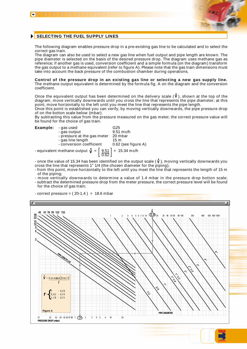
The following diagram enables pressure drop in a pre-existing gas line to be calculated and to select thecorrect gas train.The diagram can also be used to select a new gas line when fuel output and pipe length are known. Thepipe diameter is selected on the basis of the desired pressure drop. The diagram uses methane gas asreference; if another gas is used, conversion coefficient and a simple formula (on the diagram) transformthe gas output to a methane equivalent (refer to figure A). Please note that the gas train dimensions musttake into account the back pressure of the combustion chamber during operations.
Control of the pressure drop in an existing gas line or selecting a new gas supply line.The methane output equivalent is determined by the formula fig. A on the diagram and the conversioncoefficient.
Once the equivalent output has been determined on the delivery scale ( ), shown at the top of thediagram, move vertically downwards until you cross the line that represents the pipe diameter; at thispoint, move horizontally to the left until you meet the line that represents the pipe length.Once this point is established you can verify, by moving vertically downwards, the pipe pressure dropof on the botton scale below (mbar).By subtracting this value from the pressure measured on the gas meter, the correct pressure value willbe found for the choice of gas train.
Example: - gas used G25- gas output 9.51 mc/h- pressure at the gas meter 20 mbar- gas line length 15 m- conversion coefficient 0.62 (see figure A)
- equivalent methane output = 9.51 = 15.34 mc/h0.62
- once the value of 15.34 has been identified on the output scale ( ), moving vertically downwards youcross the line that represents 1" 1/4 (the chosen diameter for the piping);- from this point, move horizontally to the left until you meet the line that represents the length of 15 m
of the piping;- move vertically downwards to determine a value of 1.4 mbar in the pressure drop botton scale;- subtract the determined pressure drop from the meter pressure, the correct pressure level will be found
for the choice of gas train;
- correct pressure = ( 20-1.4 ) = 18.6 mbar
V
V
V
HYDRAULIC CIRCUIT
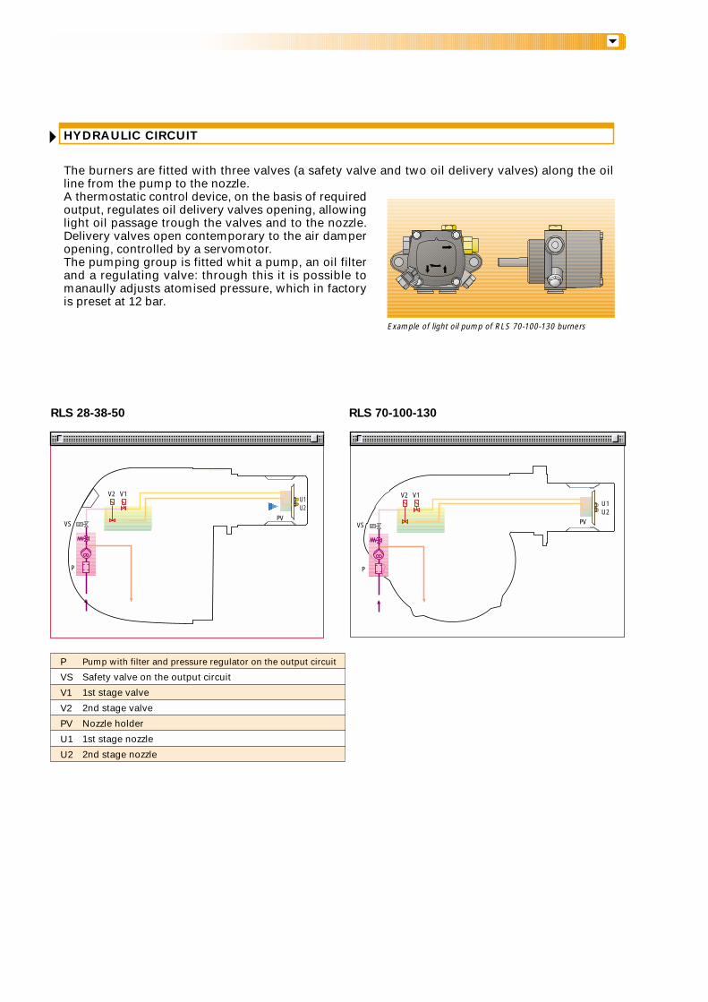
The burners are fitted with three valves (a safety valve and two oil delivery valves) along the oilline from the pump to the nozzle.A thermostatic control device, on the basis of requiredoutput, regulates oil delivery valves opening, allowinglight oil passage trough the valves and to the nozzle.Delivery valves open contemporary to the air damperopening, controlled by a servomotor.The pumping group is fitted whit a pump, an oil filterand a regulating valve: through this it is possible tomanaully adjusts atomised pressure, which in factoryis preset at 12 bar.
Example of light oil pump of RLS 70-100-130 burners
RLS 28-38-50 RLS 70-100-130
P
VS
V2 V1
PV
U1U2
P
VS
V2 V1U1U2
PV
P
VS
V1
V2
PV
U1
U2
Pump with filter and pressure regulator on the output circuit
Safety valve on the output circuit
1st stage valve
2nd stage valve
Nozzle holder
1st stage nozzle
2nd stage nozzle
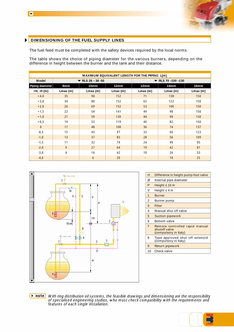
The fuel feed must be completed with the safety devices required by the local norms.
The table shows the choice of piping diameter for the various burners, depending on thedifference in height between the burner and the tank and their distance.
With ring distribution oil systems, the feasible drawings and dimensioning are the responsibilityof specialised engineering studios, who must check compatibility with the requirements andfeatures of each single installation.
Model RLS 28 – 38 -50 RLS 70 –100 –130
Piping diameter 8mm 10mm 12mm 12mm 14mm 16mm
+H, -H (m) Lmax (m) Lmax (m) Lmax (m) Lmax (m) Lmax (m) Lmax (m)
+4,0 35 90 152 71 138 150
+3,0 30 80 152 62 122 150
+2,0 26 69 152 53 106 150
+1,5 22 54 141 49 98 150
+1,0 21 59 130 44 90 150
+0,5 19 53 119 40 82 150
0 17 48 108 36 74 137
-0,5 15 43 97 32 66 123
-1,0 13 37 83 28 56 109
-1,5 11 32 74 24 49 95
-2,0 9 27 64 19 42 81
-3,0 4 16 42 10 26 53
-4,0 - 6 20 - 10 25
MAXIMUM EQUIVALENT LENGTH FOR THE PIPING L[m]
Difference in height pump-foot valve
Internal pipe diameter
Height ≤ 10 m
Height ≤ 4 m
Burner
Burner pump
Filter
Manual shut off valve
Suction pipework
Bottom valve
Remote controlled rapid manualshutoff valve(compulsory in Italy)
Type approved shut off solenoid(compulsory in Italy)
Return pipework
Check valve
H
Ø
P
V
1
2
3
4
5
6
7
8
9
10
note
7
10
9 5 V
P
+H
-H
8
1
4
10 cm2
57 3
9
6
6
DIMENSIONING OF THE FUEL SUPPLY LINES
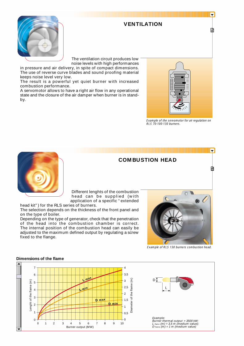
The ventilation circuit produces lownoise levels with high performances
in pressure and air delivery, in spite of compact dimensions.The use of reverse curve blades and sound proofing materialkeeps noise level very low.The result is a powerful yet quiet burner with increasedcombustion performance.A servomotor allows to have a right air flow in any operationalstate and the closure of the air damper when burner is in stand-by.
Different lenghts of the combustionhead can be supplied (with
application of a specific “extendedhead kit”) for the RLS series of burners.The selection depends on the thickness of the front panel andon the type of boiler.Depending on the type of generator, check that the penetrationof the head into the combustion chamber is correct.The internal position of the combustion head can easily beadjusted to the maximum defined output by regulating a screwfixed to the flange.
VENTILATION
COMBUSTION HEAD
Example of RLS 130 burners combustion head.
Dimensions of the flame
Example of the servomotor for air regulation onRLS 70-100-130 burners.
Example:Burner thermal output = 3500 kW;L flame (m) = 3,5 m (medium value);D flame (m) = 1 m (medium value)Burner output (MW)
0 2
3
5
1
1 3
2
4
6
7
4 5 6 7 8 9 10
Len
gh
t o
f th
e fl
ame
(m)
Dia
met
er o
f th
e fl
ame
(m)
0
4
0
0,5
1
1,5
2
2,5
3
3,5
D
L
L max
L min
D max
D min
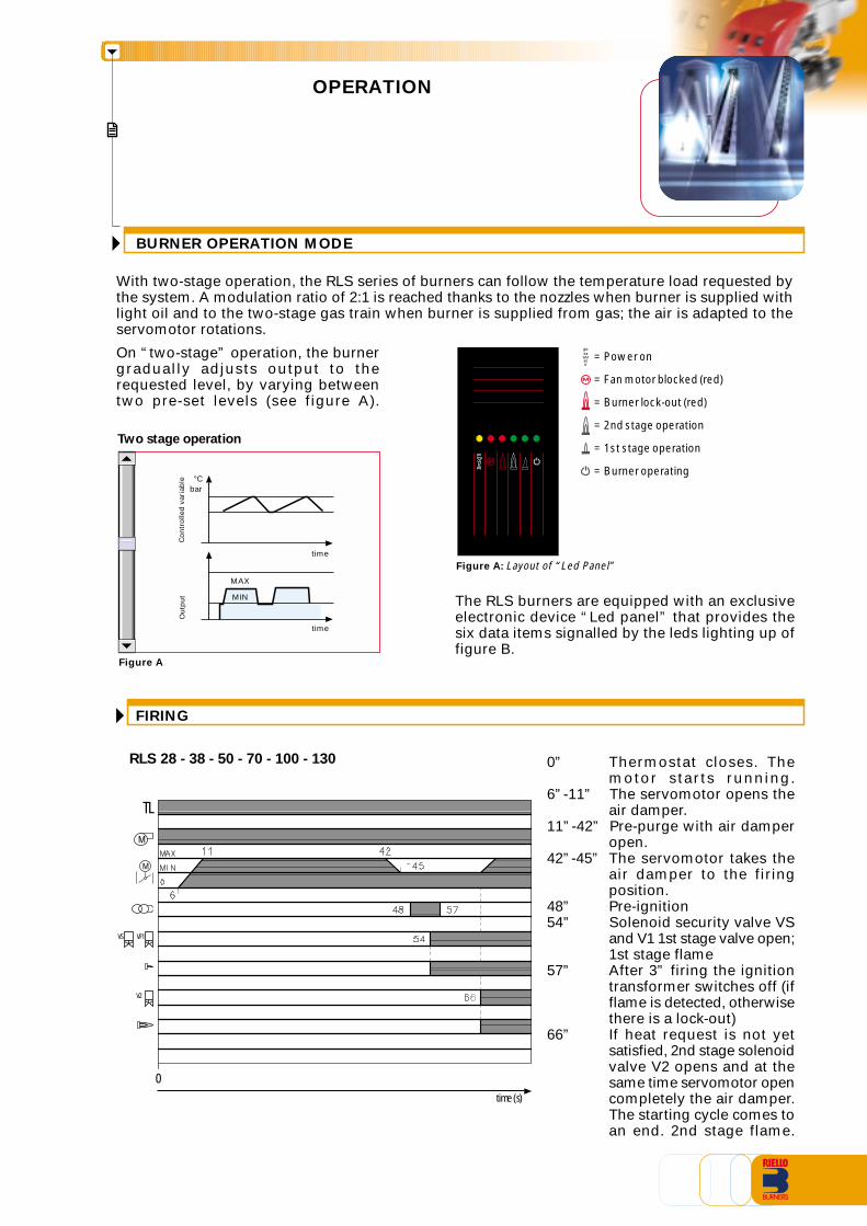
BURNER OPERATION MODE
With two-stage operation, the RLS series of burners can follow the temperature load requested bythe system. A modulation ratio of 2:1 is reached thanks to the nozzles when burner is supplied withlight oil and to the two-stage gas train when burner is supplied from gas; the air is adapted to theservomotor rotations.
FIRING
RLS 28 - 38 - 50 - 70 - 100 - 130
On “two-stage” operation, the burnergradually adjusts output to therequested level, by varying betweentwo pre-set levels (see figure A).
Figure A
Figure A: Layout of “Led Panel”
OPERATION
0” Thermostat closes. Themotor starts running.
6”-11” The servomotor opens theair damper.
11”-42” Pre-purge with air damperopen.
42”-45” The servomotor takes theair damper to the firingposition.
48” Pre-ignition54” Solenoid security valve VS
and V1 1st stage valve open;1st stage flame
57” After 3” firing the ignitiontransformer switches off (ifflame is detected, otherwisethere is a lock-out)
66” If heat request is not yetsatisfied, 2nd stage solenoidvalve V2 opens and at thesame time servomotor opencompletely the air damper.The starting cycle comes toan end. 2nd stage flame.
Two stage operation
Ou
tpu
tC
on
tro
lled
var
iab
le
bar°C
MAX
MIN
time
time
The RLS burners are equipped with an exclusiveelectronic device “Led panel” that provides thesix data items signalled by the leds lighting up offigure B.
0
TL
M
time (s)
VS VF1
V2
M
Power
M
= Power on
= Fan motor blocked (red)
= Burner lock-out (red)
= 2nd stage operation
= 1st stage operation
= Burner operating
TWO STAGE OPERATION
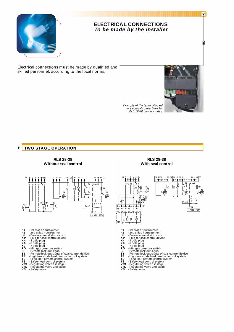
ELECTRICAL CONNECTIONSTo be made by the installer
Electrical connections must be made by qualified andskilled personnel, according to the local norms.
RLS 28-38Without seal control
RLS 28-38With seal control
h1 - 1st stage hourcounterh2 - 2nd stage hourcounterIN - Burner manual stop switchXP - Plug for seal control deviceX4 - 4 pole plugX6 - 6 pole plugX7 - 7 pole plugPG - Min gas pressure switchS - Remote lock-out signalS1 - Remote lock-out signal of seal control deviceTR - High-low mode load remote control systemTL - Load limit remote control systemTS - Safety load control systemVR1 - Regulating valve 1st stageVR2 - Regulating valve 2nd stageVS - Safety valve
h1 - 1st stage hourcounterh2 - 2nd stage hourcounterIN - Burner manual stop switchXP - Plug for seal control deviceX4 - 4 pole plugX6 - 6 pole plugX7 - 7 pole plugPG - Min gas pressure switchS - Remote lock-out signalS1 - Remote lock-out signal of seal control deviceTR - High-low mode load remote control systemTL - Load limit remote control systemTS - Safety load control systemVR1 - Regulating valve 1st stageVR2 - Regulating valve 2nd stageVS - Safety valve
V2
3 2 1 N Ph
P P N V
V2 VSVR1
PPG
PTR
h2 h1
P P
TL TS
T6A
X7L1NT1T2S3B4B5 X4T6T7T8
IN
S
PE N L
1,5 mm2
~50Hz 230V
Example of the terminal boardfor electrical connections for
RLS 28-38 burner models
3 2 1 N PhX6
T6 V2 T8 N V
VR2 VR1 VS
PGP
XPL1NB5T6T7T8
VPS
S1
B5T6T7T8 X4 B4 S3 T2 T1 N L1 X7
T6A
TRh2 h1
IN
TSTL
S
P P P
1,5 mm2
PE N L
~50Hz 230V
X6
L3PE L2L1
TL
IN
T6AP
PG
P
P P
1 2 3 4 5 6 7
VS VR1 VR2
L3L2L1 N LMB
TS STR
F
L
NV1 V2
N NN V2 8 9 10 11V1
S1
XP
LN
T8 T6
VPS
T8 T7 T6 B5 N L1
~M3~50Hz 230V33N 50Hz 400/230V
~50Hz 230V
TS
L3PE L2L1
TL
IN
T6AS
PPG
P
MB L1 L2 L3 N L 1 2 3
P
P
P P
4 5 6 7
N L
F
L
N NNV1 V2 8 9 10 11NV1 V2
VS VR1 VR2
TR
~M3~50Hz 230V33N 50Hz 400/230V
~50Hz 230V
~M3~50Hz 230V33N 50Hz 400/230V
N3 2 1 Ph X7L1NT1T2S3B4B5 X4T6T7T8
h2 h1TR TL
PPP
INT6A
TS
S
1,5 mm2
1,5 mm2
PPG
VR2 VR1 VS
L3 PE L2 L1
6A
X6 X5 L3 N L2 L1
V2P P N V
PE N L
~50Hz 230VT8 T7 T6 B5 N L1
h2 h1
1,5 mm2
1,5 mm2
N3 2 1 PhX6 X5 B5T6T7T8 X4 B4 S3 T2 T1 N L1 X7
TS
L3 PE L2 L1
TL
INT6A
PPG
VPS
S1
NV2 T8T6 V
VR2 VR1 VS
L3 N L2 L1
XP
6A
TR S
P P P
PE N L
~M3~50Hz 230V33N 50Hz 400/230V
~50Hz 230V
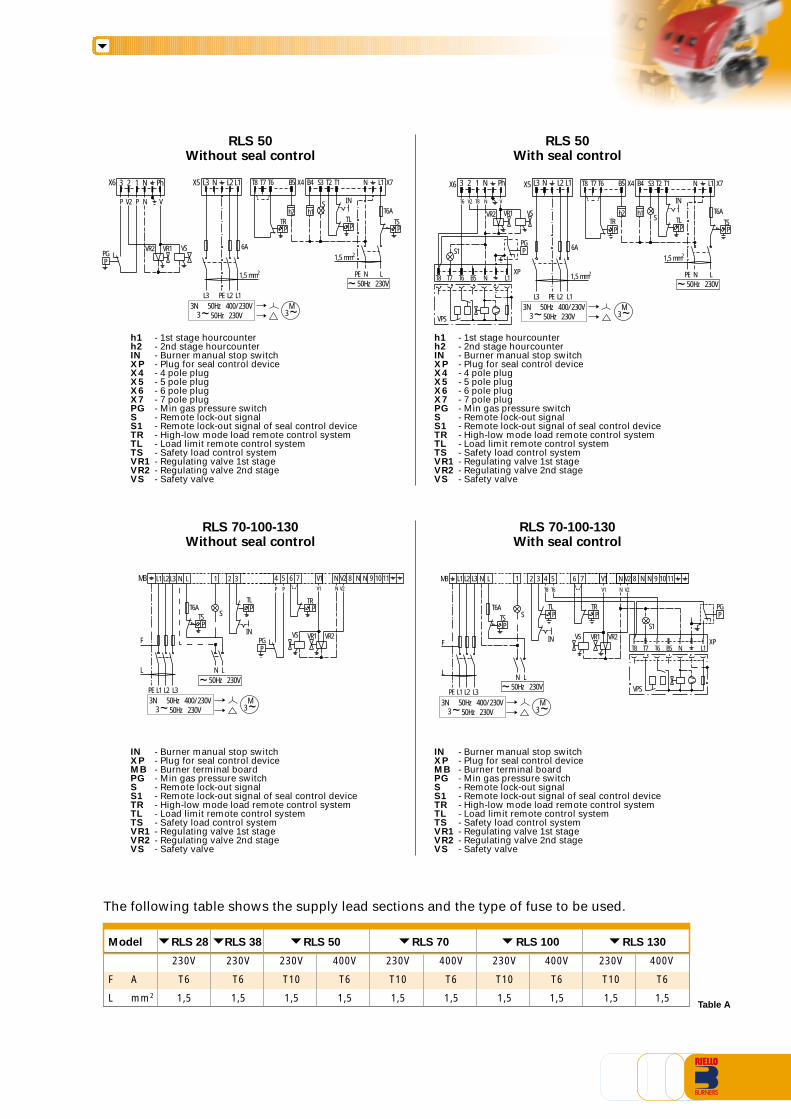
RLS 50Without seal control
RLS 50With seal control
h1 - 1st stage hourcounterh2 - 2nd stage hourcounterIN - Burner manual stop switchXP - Plug for seal control deviceX4 - 4 pole plugX5 - 5 pole plugX6 - 6 pole plugX7 - 7 pole plugPG - Min gas pressure switchS - Remote lock-out signalS1 - Remote lock-out signal of seal control deviceTR - High-low mode load remote control systemTL - Load limit remote control systemTS - Safety load control systemVR1 - Regulating valve 1st stageVR2 - Regulating valve 2nd stageVS - Safety valve
IN - Burner manual stop switchXP - Plug for seal control deviceMB - Burner terminal boardPG - Min gas pressure switchS - Remote lock-out signalS1 - Remote lock-out signal of seal control deviceTR - High-low mode load remote control systemTL - Load limit remote control systemTS - Safety load control systemVR1 - Regulating valve 1st stageVR2 - Regulating valve 2nd stageVS - Safety valve
RLS 70-100-130Without seal control
RLS 70-100-130With seal control
IN - Burner manual stop switchXP - Plug for seal control deviceMB - Burner terminal boardPG - Min gas pressure switchS - Remote lock-out signalS1 - Remote lock-out signal of seal control deviceTR - High-low mode load remote control systemTL - Load limit remote control systemTS - Safety load control systemVR1 - Regulating valve 1st stageVR2 - Regulating valve 2nd stageVS - Safety valve
h1 - 1st stage hourcounterh2 - 2nd stage hourcounterIN - Burner manual stop switchXP - Plug for seal control deviceX4 - 4 pole plugX5 - 5 pole plugX6 - 6 pole plugX7 - 7 pole plugPG - Min gas pressure switchS - Remote lock-out signalS1 - Remote lock-out signal of seal control deviceTR - High-low mode load remote control systemTL - Load limit remote control systemTS - Safety load control systemVR1 - Regulating valve 1st stageVR2 - Regulating valve 2nd stageVS - Safety valve
The following table shows the supply lead sections and the type of fuse to be used.
Table A
Model RLS 28 RLS 38 RLS 50 RLS 70 RLS 100 RLS 130
230V 230V 230V 400V 230V 400V 230V 400V 230V 400V
F A T6 T6 T10 T6 T10 T6 T10 T6 T10 T6
L mm2 1,5 1,5 1,5 1,5 1,5 1,5 1,5 1,5 1,5 1,5
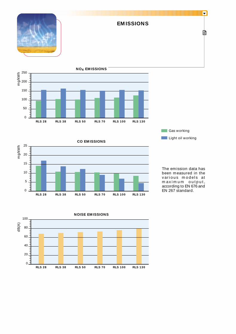
EMISSIONS
The emission data hasbeen measured in thevarious models atmax imum output ,according to EN 676 andEN 267 standard.
NOISE EMISSIONS
dB
(A)
0
20
40
60
80
100
CO EMISSIONS
mg
/kW
h
0
5
10
15
20
25
RLS 28 RLS 130RLS 100
NOx EMISSIONS
mg
/kW
h
0
50
100
150
200
250
RLS 130RLS 100
Gas working
Light oil working
RLS 70RLS 50RLS 38
RLS 28 RLS 70RLS 50RLS 38
RLS 28 RLS 130RLS 100RLS 70RLS 50RLS 38
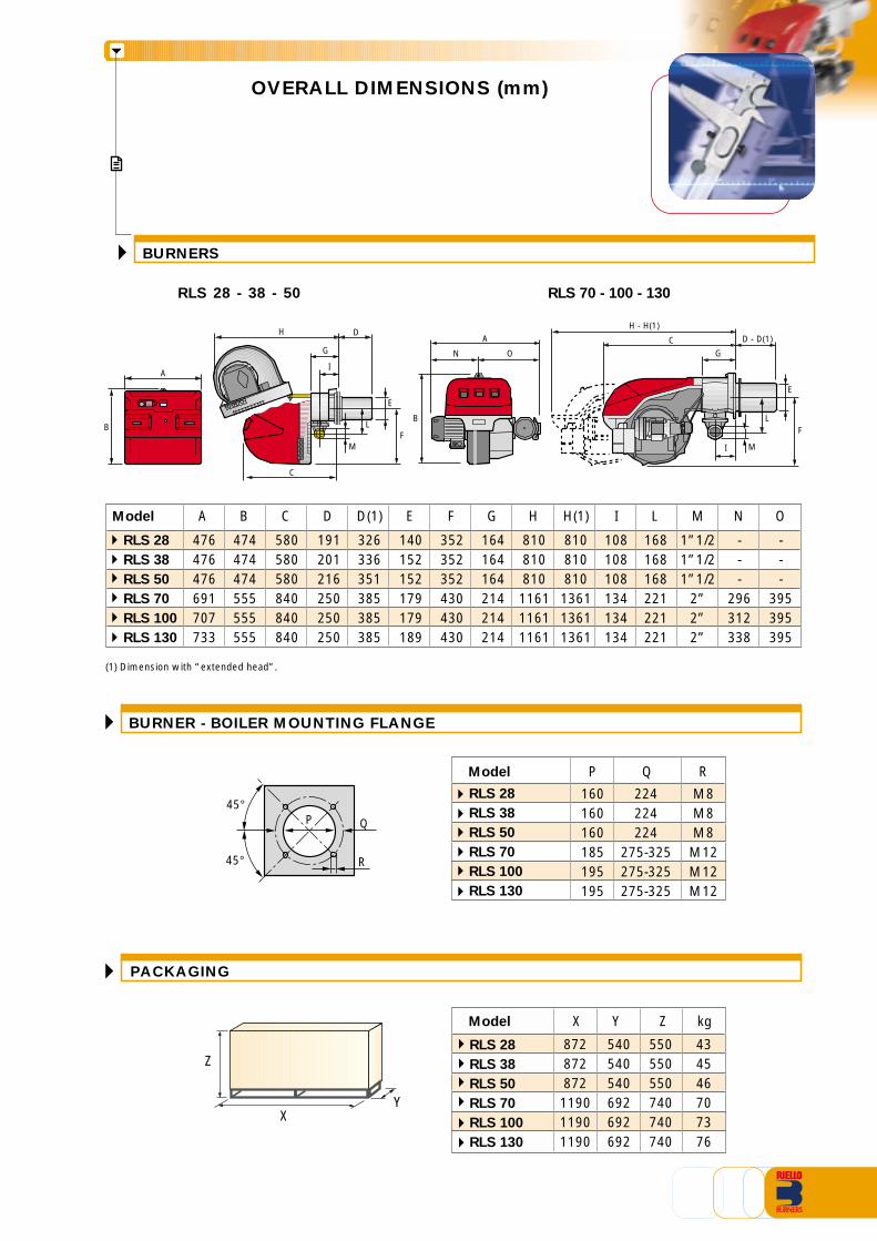
OVERALL DIMENSIONS (mm)
BURNERS
RLS 28 - 38 - 50 RLS 70 - 100 - 130
PACKAGING
X
Z
Y
394142
RLS 28
RLS 38
RLS 50
RLS 70
RLS 100
RLS 130
434546707376
Model X Y kg
872872872119011901190
540540540692692692
Z
550550550740740740
BURNER - BOILER MOUNTING FLANGE
R
Q
45°
45°
P
RQ
160160160185195195
M8M8M8M12M12M12
224224224
275-325275-325275-325
P
RLS 28
RLS 38
RLS 50
RLS 70
RLS 100
RLS 130
Model
D
C
E
HD - D(1)C
H - H(1)A
BL
M
I
G
F
G
I
L
M
F
E
N O
A
B
Model
RLS 28
RLS 38
RLS 50
RLS 70
RLS 100
RLS 130
(1) Dimension with “extended head”.
H(1)
810810810136113611361
A
476476476691707733
B
474474474555555555
C
580580580840840840
D
191201216250250250
D(1)
326336351385385385
E
140152152179179189
F
352352352430430430
G
164164164214214214
H
810810810116111611161
O
---
395395395
I
108108108134134134
L
168168168221221221
M
1”1/21”1/21”1/2
2”2”2”
N
---
296312338
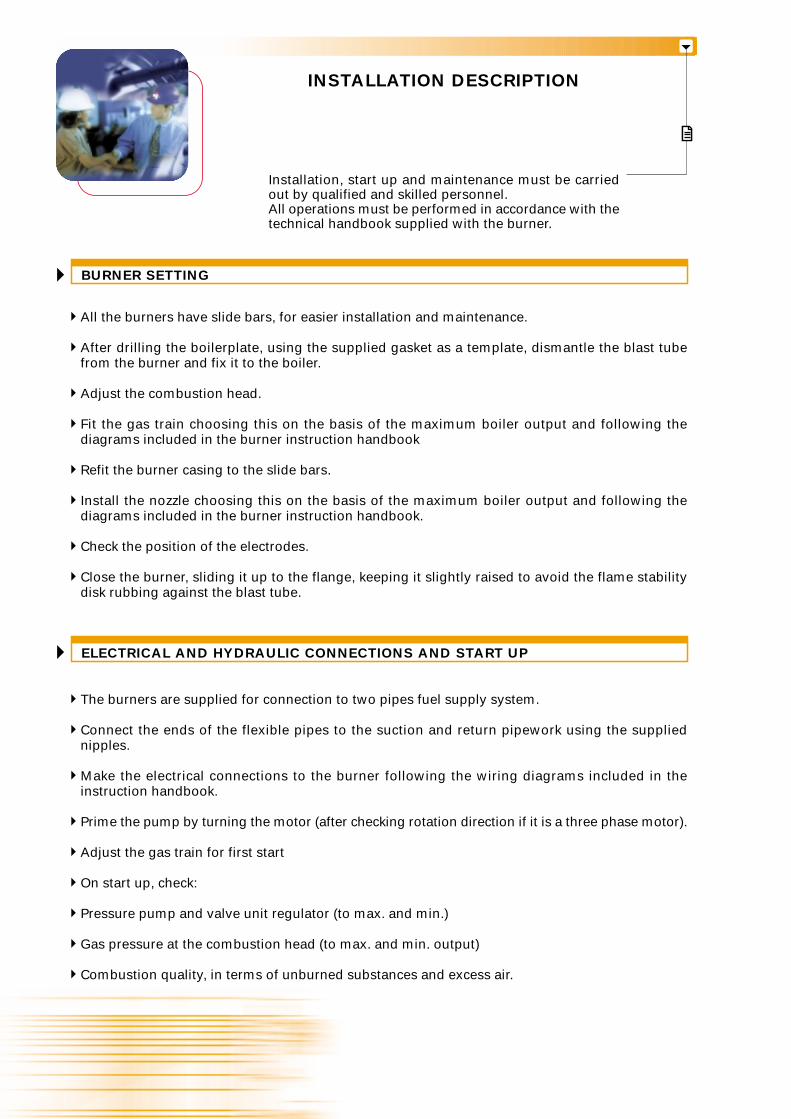
INSTALLATION DESCRIPTION
BURNER SETTING
Installation, start up and maintenance must be carriedout by qualified and skilled personnel.All operations must be performed in accordance with thetechnical handbook supplied with the burner.
ELECTRICAL AND HYDRAULIC CONNECTIONS AND START UP
All the burners have slide bars, for easier installation and maintenance.
After drilling the boilerplate, using the supplied gasket as a template, dismantle the blast tubefrom the burner and fix it to the boiler.
Adjust the combustion head.
Fit the gas train choosing this on the basis of the maximum boiler output and following thediagrams included in the burner instruction handbook
Refit the burner casing to the slide bars.
Install the nozzle choosing this on the basis of the maximum boiler output and following thediagrams included in the burner instruction handbook.
Check the position of the electrodes.
Close the burner, sliding it up to the flange, keeping it slightly raised to avoid the flame stabilitydisk rubbing against the blast tube.
The burners are supplied for connection to two pipes fuel supply system.
Connect the ends of the flexible pipes to the suction and return pipework using the suppliednipples.
Make the electrical connections to the burner following the wiring diagrams included in theinstruction handbook.
Prime the pump by turning the motor (after checking rotation direction if it is a three phase motor).
Adjust the gas train for first start
On start up, check:
Pressure pump and valve unit regulator (to max. and min.)
Gas pressure at the combustion head (to max. and min. output)
Combustion quality, in terms of unburned substances and excess air.
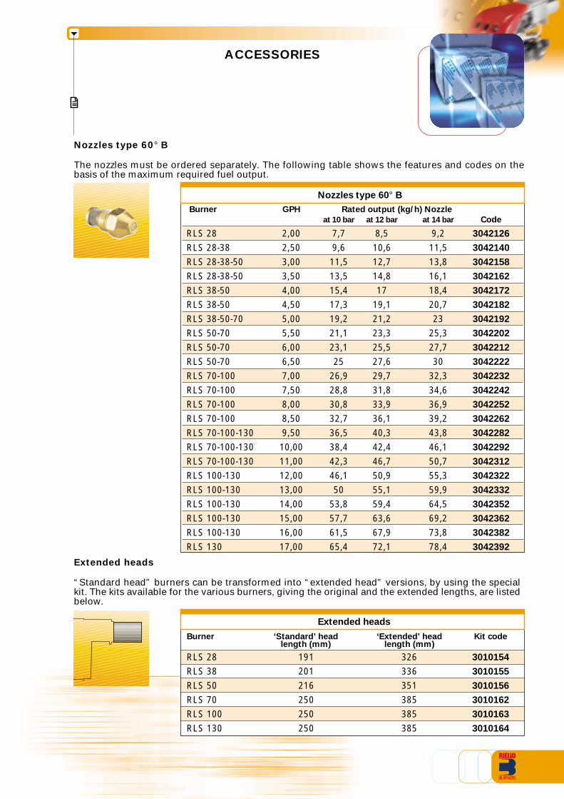
ACCESSORIES
Burner GPH Rated output (kg/h) Nozzle
at 10 bar at 12 bar at 14 bar Code
RLS 28 2,00 7,7 8,5 9,2 3042126
RLS 28-38 2,50 9,6 10,6 11,5 3042140
RLS 28-38-50 3,00 11,5 12,7 13,8 3042158
RLS 28-38-50 3,50 13,5 14,8 16,1 3042162
RLS 38-50 4,00 15,4 17 18,4 3042172
RLS 38-50 4,50 17,3 19,1 20,7 3042182
RLS 38-50-70 5,00 19,2 21,2 23 3042192
RLS 50-70 5,50 21,1 23,3 25,3 3042202
RLS 50-70 6,00 23,1 25,5 27,7 3042212
RLS 50-70 6,50 25 27,6 30 3042222
RLS 70-100 7,00 26,9 29,7 32,3 3042232
RLS 70-100 7,50 28,8 31,8 34,6 3042242
RLS 70-100 8,00 30,8 33,9 36,9 3042252
RLS 70-100 8,50 32,7 36,1 39,2 3042262
RLS 70-100-130 9,50 36,5 40,3 43,8 3042282
RLS 70-100-130 10,00 38,4 42,4 46,1 3042292
RLS 70-100-130 11,00 42,3 46,7 50,7 3042312
RLS 100-130 12,00 46,1 50,9 55,3 3042322
RLS 100-130 13,00 50 55,1 59,9 3042332
RLS 100-130 14,00 53,8 59,4 64,5 3042352
RLS 100-130 15,00 57,7 63,6 69,2 3042362
RLS 100-130 16,00 61,5 67,9 73,8 3042382
RLS 130 17,00 65,4 72,1 78,4 3042392
Nozzles type 60° B
The nozzles must be ordered separately. The following table shows the features and codes on thebasis of the maximum required fuel output.
Nozzles type 60° B
Extended heads
Extended heads
“Standard head” burners can be transformed into “extended head” versions, by using the specialkit. The kits available for the various burners, giving the original and the extended lengths, are listedbelow.
RLS 28RLS 38RLS 50RLS 70RLS 100RLS 130
Burner ‘Extended’ headlength (mm)
326336351385385385
191201216250250250
‘Standard’ headlength (mm)
Kit code
3010154
3010155
3010156
3010162
3010163
3010164
Degasing unit with filterCode
3010055
Degasing unit without filterCode
3010054
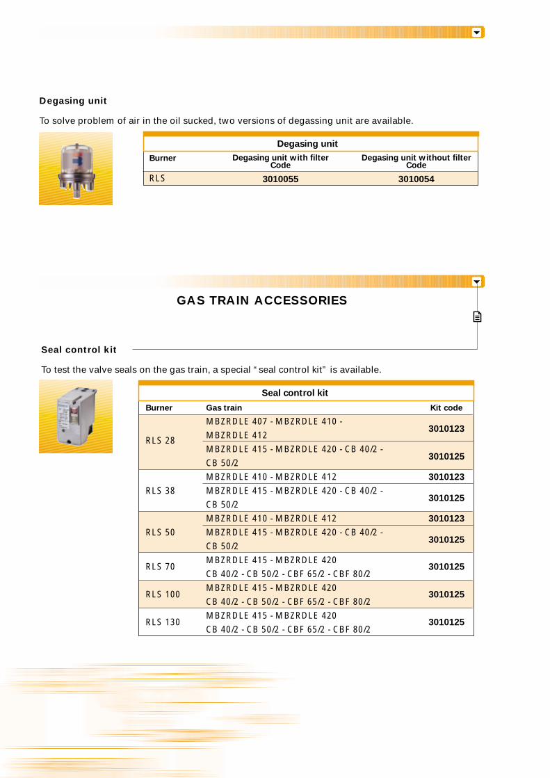
Degasing unit
Degasing unit
To solve problem of air in the oil sucked, two versions of degassing unit are available.
RLS
Burner
GAS TRAIN ACCESSORIES
Seal control kit
To test the valve seals on the gas train, a special “seal control kit” is available.
Burner Gas train Kit code
MBZRDLE 407 - MBZRDLE 410 -
RLS 28 MBZRDLE 4123010123
MBZRDLE 415 - MBZRDLE 420 - CB 40/2 -CB 50/2
3010125
MBZRDLE 410 - MBZRDLE 412 3010123
RLS 38 MBZRDLE 415 - MBZRDLE 420 - CB 40/2 -CB 50/2
3010125
MBZRDLE 410 - MBZRDLE 412 3010123
RLS 50 MBZRDLE 415 - MBZRDLE 420 - CB 40/2 -CB 50/2
3010125
RLS 70MBZRDLE 415 - MBZRDLE 420
3010125CB 40/2 - CB 50/2 - CBF 65/2 - CBF 80/2
RLS 100MBZRDLE 415 - MBZRDLE 420
3010125CB 40/2 - CB 50/2 - CBF 65/2 - CBF 80/2
RLS 130MBZRDLE 415 - MBZRDLE 420
3010125CB 40/2 - CB 50/2 - CBF 65/2 - CBF 80/2
Seal control kit
CBF 65/1 - CBF 80/1CBF 65/1 - CBF 80/1CBF 65/1 - CBF 80/1
Gas train CodeSpring
3010133
3010135
3090456
Red from 25 to 55 mbarBlack from 60 to 110 mbarPink from 90 to 150 mbar
Burner Gas train Dimensions Adaptercode
MBZRDLE 4073000824
MBZRDLE 410RLS 28 CB 50/2 - CB 50/2 CT
MBZRDLE 420 3000822
MBZRDLE 420 CT
MBZRDLE 410 3000824
RLS 38 MBZRDLE 420MBZRDLE 420 CT 3000822
CB 50/2 - CB 50/2 CT
MBZRDLE 410 3000824
RLS 50 MBZRDLE 420MBZRDLE 420 CT 3000822
CB 50/2 - CB 50/2 CT
MBZRDLE 415 - CB 40/2 3000843
RLS 70 CBF 65/2 - CBF 65/2 CT 3000825
CBF 80/2 - CBF 80/2 CT 3000826
MBZRDLE 415 - CB 40/2 3000843
RLS 100 CBF 65/2 - CBF 65/2 CT 3000825
CBF 80/2 - CBF 80/2 CT 3000826
MBZRDLE 415 - CB 40/2 3000843
RLS 130 CBF 65/2 - CBF 65/2 CT 3000825
CBF 80/2 - CBF 80/2 CT 3000826
1" 1/23/4"
2" 1" 1/2
1" 1/23/4"
2" 1" 1/2
1" 1/23/4"
1" 1/2 2"
2" 1" 1/2
1" 1/2 2"
1" 1/2 2"
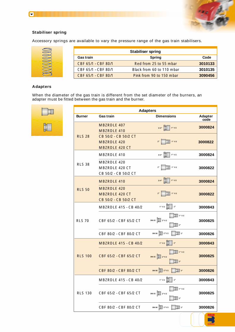
Stabiliser spring
Accessory springs are available to vary the pressure range of the gas train stabilisers.
Adapters
When the diameter of the gas train is different from the set diameter of the burners, anadapter must be fitted between the gas train and the burner.
1" 1/2
2"
DN 65 2"1/2
DN 80 2"1/2 2"
1" 1/2
2"
DN 65 2"1/2
DN 80 2"1/2 2"
1" 1/2
2"
DN 65 2"1/2
DN 80 2"1/2 2"
Stabiliser spring
Adapters
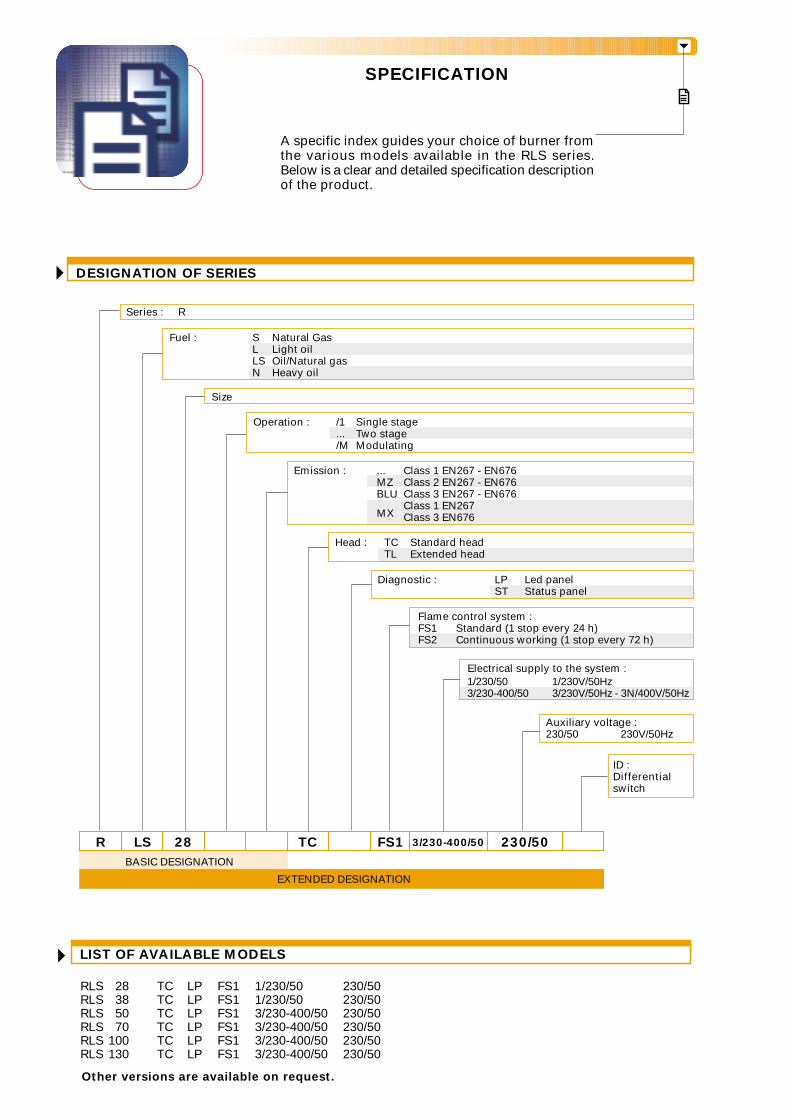
SPECIFICATION
A specific index guides your choice of burner fromthe various models available in the RLS series.Below is a clear and detailed specification descriptionof the product.
LIST OF AVAILABLE MODELS
RLS 28 TC LP FS1 1/230/50 230/50RLS 38 TC LP FS1 1/230/50 230/50RLS 50 TC LP FS1 3/230-400/50 230/50RLS 70 TC LP FS1 3/230-400/50 230/50RLS 100 TC LP FS1 3/230-400/50 230/50RLS 130 TC LP FS1 3/230-400/50 230/50
Other versions are available on request.
Electrical supply to the system :1/230/50 1/230V/50Hz3/230-400/50 3/230V/50Hz - 3N/400V/50Hz
DESIGNATION OF SERIES
R LS 28 TC FS1 3/230-400/50 230/50
Size
Fuel : S Natural GasL Light oilLS Oil/Natural gasN Heavy oil
Series : R
ID :Differentialswitch
BASIC DESIGNATION
EXTENDED DESIGNATION
Operation : /1 Single stage... Two stage/M Modulating
Emission : ... Class 1 EN267 - EN676MZ Class 2 EN267 - EN676BLU Class 3 EN267 - EN676
MXClass 1 EN267Class 3 EN676
Head : TC Standard headTL Extended head
Diagnostic : LP Led panelST Status panel
Auxiliary voltage :230/50 230V/50Hz
Flame control system : FS1 Standard (1 stop every 24 h)FS2 Continuous working (1 stop every 72 h)
Burner:Monobloc forced draught dual fuel burner, two stage operation, made up of:- Air suction circuit lined with sound-proofing material- Fan with reverse curve blades- Fan starting motor- Air damper for air setting controlled by a servomotor- Minimum air pressure switch- Combustion head, that can be set on the basis of required output- Gears pump for high pressure fuel supply- Pump starting motor- Oil safety valves- Two oil valves (1st and 2nd stage)- Flame control panel- Electronic device to check all burners operational modes (Led Panel)- UV photocell for flame detection- Burner on/off switch- Oil/Gas selector- Manual 1st and 2nd stage switch- Plugs for electrical connections (RLS 28-38-50)- Flame inspection window- Slide bars for easier installation and maintenance- Protection filter against radio interference- IP 44 electric protection level.
Conforming to:- 89/336/EEC directive (electromagnetic compatibility)- 73/23/EEC directive (low voltage)- 92/42/EEC directive (performance)- 98/37/EEC directive (machinery)- EN 267 (liquid fuel burners)- EN 676 (gas fuel burners).
Standard equipment:- 1 gas train gasket- 1 flange gasket- 4 screws for fixing the flange- 1 thermal screen- 4 screws for fixing the burner flange to the boiler- 2 flexible pipes for connection to the oil supply network- 2 nipples for connection to the pump with gaskets- Kit for transformation to LPG- Fairleads for electrical connections (for RLS 28-38-50 model)- Instruction handbook for installation, use and maintenance- Spare parts catalogue.
Available accessories to be ordered separately:- Nozzles- Head extension kit- Degasing unit- Adapters- Stabiliser spring- Seal control kit.
PRODUCT SPECIFICATION

RIELLO S.p.A. - Via degli Alpini, 1 - 37045 LEGNAGO (VR) ItalyTel. ++39.0442630111 - Fax ++39.044221980
Internet: http://www.rielloburners.com - E-mail: [email protected] 9001 Cert. n. 0061
Since the Company is constantly engaged in the production improvement, the aesthetic anddimensional features, the technical data, the equipment and the accessories can be changed.
This document contains confidential and proprietary information of RIELLO S.p.A.Unless authorised, this information shall not be divulged, nor duplicated in whole or in part.
Line
agra
fica