Embed Size (px)
Citation preview
www.maag.com
MS-SeriesTwin Screw Pumps
W h e r e I n n o v a t i o n F l o w s
www.maag.com
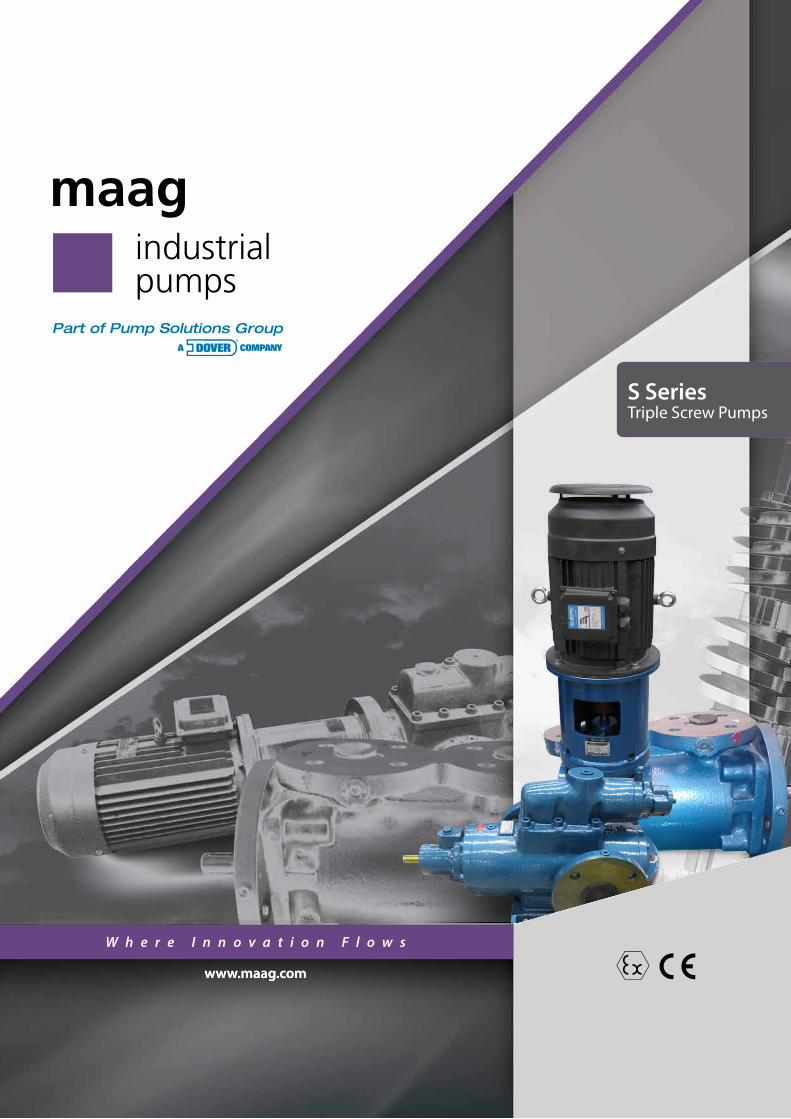
S SeriesTriple Screw Pumps

2
TripleScrew Pump
S E R I E S
• Chemicals• Adhesives• Food and beverage• Soap• Petrochemicals• Polymers
• Crude oil• Asphalt• Diesel• Lube oil• Kerosene• Oilfields
• Residuals• Bulk transfer• Loading/unloading• Terminals• Shipping
S SeriesPumps are Ideally Suited For…
Maag, part of Dover Corporation’s Pump Solutions Group (PSG®), is a leading global provider of innovative, high-quality industrial twin-screw, triple-screw and multi-phase pumps for the safe and efficient transfer of liquids.
Maag is proud to offer the S Series. This durable screw pump line is perfectly suited to applications with the Process, Energy, Transport and Marine markets. Maag S Series pumps offer a wide range of highly customizable pumps and systems for the world’s most demanding applications.
Our world-class distributor network ensures that you will have access to the pump you need when you need it. We are devoted to your business’s success servicing your needs with world-class products, delivery and best of class expertise. Put us to the test today and contact your local distributor at www.maag.com
More Cost-Effective Pumping SolutionA Safer, Greener,
3
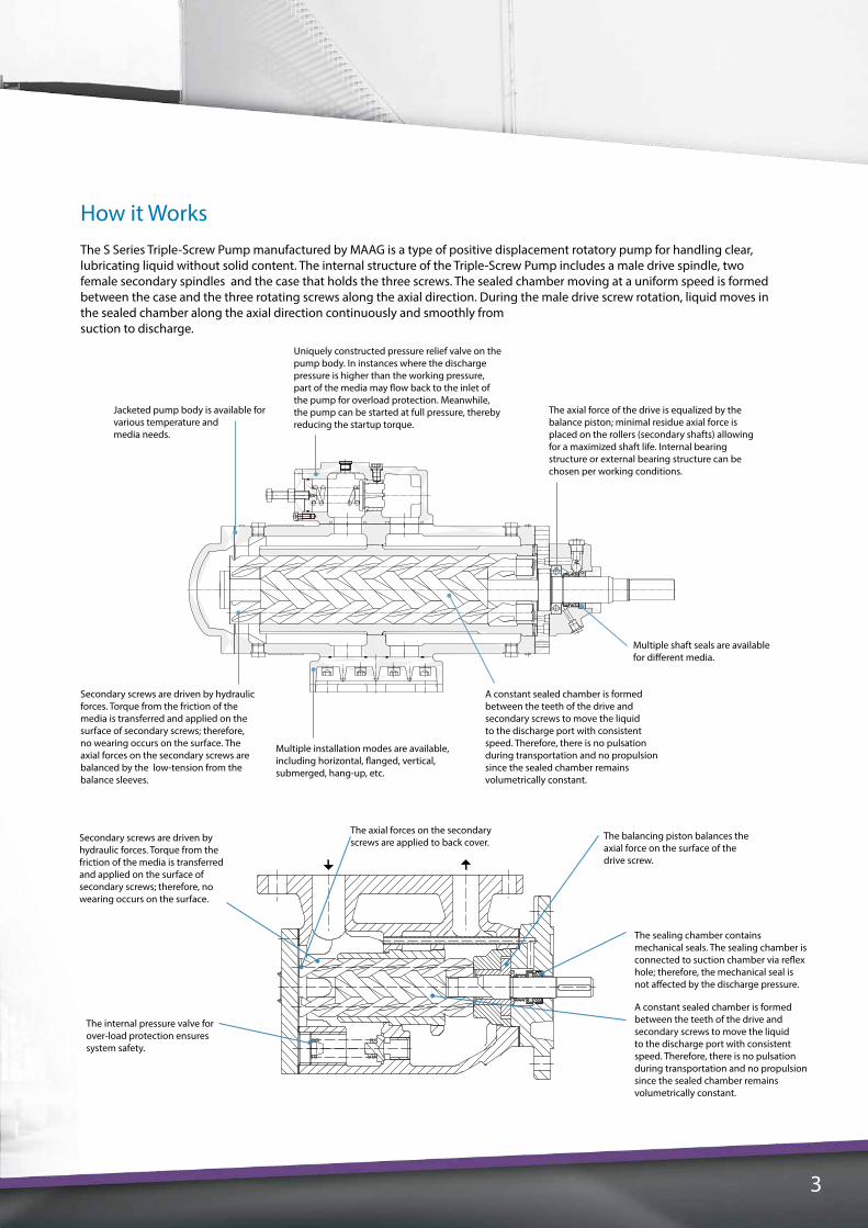
How it WorksThe S Series Triple-Screw Pump manufactured by MAAG is a type of positive displacement rotatory pump for handling clear, lubricating liquid without solid content. The internal structure of the Triple-Screw Pump includes a male drive spindle, two female secondary spindles and the case that holds the three screws. The sealed chamber moving at a uniform speed is formed between the case and the three rotating screws along the axial direction. During the male drive screw rotation, liquid moves in the sealed chamber along the axial direction continuously and smoothly from suction to discharge.
The axial force of the drive is equalized by the balance piston; minimal residue axial force is placed on the rollers (secondary shafts) allowing for a maximized shaft life. Internal bearing structure or external bearing structure can be chosen per working conditions.
Secondary screws are driven by hydraulic forces. Torque from the friction of the media is transferred and applied on the surface of secondary screws; therefore, no wearing occurs on the surface. The axial forces on the secondary screws are balanced by the low-tension from the balance sleeves.
Multiple installation modes are available, including horizontal, flanged, vertical, submerged, hang-up, etc.
A constant sealed chamber is formed between the teeth of the drive and secondary screws to move the liquid to the discharge port with consistent speed. Therefore, there is no pulsation during transportation and no propulsion since the sealed chamber remains volumetrically constant.
Multiple shaft seals are available for different media.
Uniquely constructed pressure relief valve on the pump body. In instances where the discharge pressure is higher than the working pressure, part of the media may flow back to the inlet of the pump for overload protection. Meanwhile, the pump can be started at full pressure, thereby reducing the startup torque.
Jacketed pump body is available for various temperature and media needs.
Secondary screws are driven by hydraulic forces. Torque from the friction of the media is transferred and applied on the surface of secondary screws; therefore, no wearing occurs on the surface.
The axial forces on the secondary screws are applied to back cover.
The balancing piston balances the axial force on the surface of the drive screw.
The internal pressure valve for over-load protection ensures system safety.
The sealing chamber contains mechanical seals. The sealing chamber is connected to suction chamber via reflex hole; therefore, the mechanical seal is not affected by the discharge pressure.
A constant sealed chamber is formed between the teeth of the drive and secondary screws to move the liquid to the discharge port with consistent speed. Therefore, there is no pulsation during transportation and no propulsion since the sealed chamber remains volumetrically constant.
(此图为“三. 结构特点”下的图纸)
4
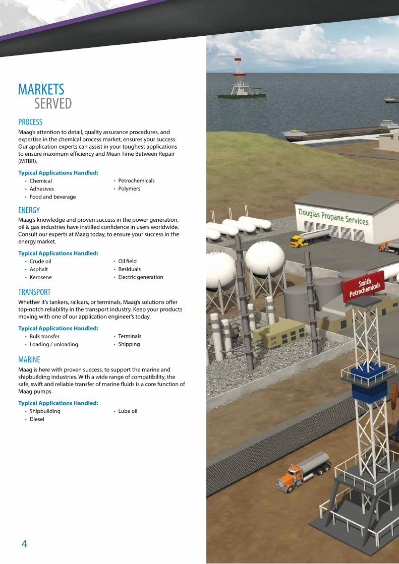
PROCESS Maag’s attention to detail, quality assurance procedures, and expertise in the chemical process market, ensures your success. Our application experts can assist in your toughest applications to ensure maximum efficiency and Mean Time Between Repair (MTBR).
Typical Applications Handled:• Chemical• Adhesives• Food and beverage
• Petrochemicals• Polymers
ENERGY Maag’s knowledge and proven success in the power generation, oil & gas industries have instilled confidence in users worldwide. Consult our experts at Maag today, to ensure your success in the energy market.
Typical Applications Handled:• Crude oil• Asphalt• Kerosene
• Oil field• Residuals• Electric generation
TRANSPORT Whether it’s tankers, railcars, or terminals, Maag’s solutions offer top-notch reliability in the transport industry. Keep your products moving with one of our application engineer’s today.
Typical Applications Handled:• Bulk transfer• Loading / unloading
• Terminals• Shipping
MARINE Maag is here with proven success, to support the marine and shipbuilding industries. With a wide range of compatibility, the safe, swift and reliable transfer of marine fluids is a core function of Maag pumps.
Typical Applications Handled:• Shipbuilding• Diesel
• Lube oil
MARKETS SERVED

5

6
MODEL SELECTION A. User-Provided Parameters
• Working temperature of the media, T• Viscosity at working temperature, v• Suction pressure (or vacuum), P1• Discharge pressure, P2• Working flow, Q• Installation mode• Any other supporting requirements
B. Notes for Model Selection• Select proper structure based on the features of the media
being pumped.• Select proper speed based on the viscosity of the media. If
media viscosity is > 760 mm2/s, please contact company for assistance.
• Select the model based on the flow and pressure from the Series Triple-Screw Pump performance data sheet.
• Check and identify the NPSHr value from the cavitation redundancy sheet based on the pump specification, speed and viscosity. It should be ensured that the NPSHr < NPSHa (cavitation redundancy of the inlet piping). Otherwise, a pump with one size larger or lower speed should be selected.
• After selecting the pump specification, identify the shaft power (N∙m) from the performance chart. When selecting mating motors, N∙m >= K x N.
• Please refer to the table below for the value of K.
N (kW) N <= 5 5 < N <= 10 10 < N <= 50 N > 50K 1.25 1.2 1.15 1.1
NOTE: The data in the table are subject to revision without prior notice.
Triple Screw Pumps
Series L/min gpm bar psi mm2/s (cSt) °C °F3N 10-5,300 2.6-1,400 up to 40 up to 580 3-5,000 280 5363M 10-2,200 2.6-581 up to 100 up to 1450 3-5,000 280 5363PF 2-130 0.5-34 up to 40 up to 580 3-750 150 302
Capacity Diff. Pressure Viscosity Max. Temp.

7
3X H 210 R 46 E 6.7 Y – W23
Materials code
Pump casing heating type
Seal type
Structural feature
Helix angle of the drive spindle
Thread orientation of the drive spindle
Size code
Installation code
Series code
Series Key Features Flow RateL/min (gpm)
Max. Discharge Pressure Bar (psig)
Viscosity(mm2/s)
Operating Temperature °C (°F)
3MHigh pressure,
single suction, axial hydraulic balance
10 – 2,200 (2.6 – 581) 100 (1450) 3-5,000 ≤ 280 (536)
3NLow pressure,
single suction, axial hydraulic balance
10 – 5,300 (2.6 – 1,400) 40 (580) 3-5,000 ≤ 280 (536)
Performance Data
Installation mode H F S G E
Description Foot installation Flange installation Vertical installation Horizontal U installation Barrel-type pump unit
Illustration
*Flanged connections can be provided upon request; applicable for small pumps only.
Installation Mode
Specification and Helix Angle
Specification Code 40 80 120 210 280 440 660 940 1300 1700 2200 2900 3600 5300
Helix Angle(degrees)
38 36 42 40 43 40 40 42 38 42 42 40 46 46
46 42 46 46 46 46 44 46 42 46 46 46
54 46 54 54 54 52 46 50 46
54 54 51 54 54
54Maag reserves the right to change the data in the table without prior notice.
The pump specification code is determined based on a pump running at 1,450 r/min, with helix angle of 46 degrees. There are 14 specification codes for 3N pumps in total.
8
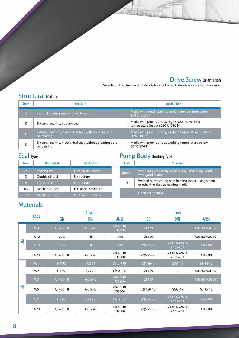
Code Structure Applications
U Internal bearing, multiple seal types Media with good lubricity, working temperature below 150°C (302°F)
K External bearing, packing seal Media with poor lubricity, high viscosity, working temperature below ≤280°C (536°F)
E External bearing, mechanical seal, with greasing port on bearing
Media with poor lubricity, working temperature 80-150°C (176 - 302°F)
D External bearing, mechanical seal, without greasing port on bearing
Media with poor lubricity, working temperature below 80 °C (176°F)
Code Structure
[blank] Standard pump body for handling lubricating liquid with good fluidity
Y Welded pump casing with heating jacket, using steam or other hot fluid as heating media
E Electrical heating
Code Description Application
2 Packing seal U and K structures
3 Double oil seal U structure
4 Triple oil seal U structure
6.7 Mechanical seal E, D and U structure
12.1 Mechanical seal U, D and E structure
View from the drive end: R stands for clockwise; L stands for counter clockwise.Drive Screw Orientation
Structural Feature
Seal Type Pump Body Heating Type
Materials
CodeCasing Liner
GB DIN ANSI GB DIN ANSI
3M
W3 QT400-18 GGG-40 60-40-18 F32800 ZL109 - A03360/A03361
W12 20G HII 1018 ZL109 - A03360/A03361
W13 20G HII 1018 ZQSn5-5-5 G-CUSN5ZNPB2.1096.01 C83600
W23 QT400-18 GGG-40 60-40-18 F32800 ZQSn5-5-5 G-CUSN5ZNPB
2.1096.01 C83600
3N
W1 HT250 GG 25 Class 35B QT450-10 GGG-45 65-45-12
W2 HT250 GG 25 Class 35B ZL109 - A03360/A03361
W3 QT400-18 GGG-40 60-40-18 F32800 ZL109 - A03360/A03361
W5 QT400-18 GGG-40 60-40-18 F32800 QT450-10 GGG-45 65-45-12
W21 HT250 GG 25 Class 35B ZQSn5-5-5 G-CUSN5ZNPB2.1096.01 C83600
W23 QT400-18 GGG-40 60-40-18 F32800 ZQSn5-5-5 G-CUSN5ZNPB
2.1096.01 C83600
9
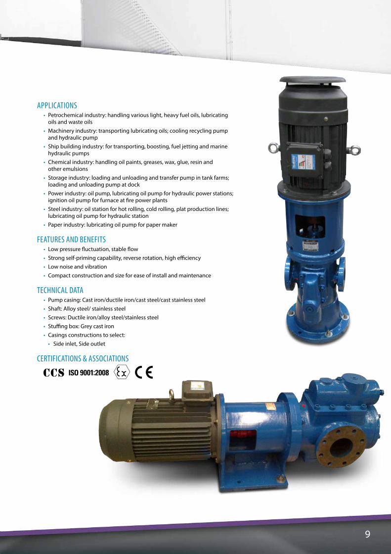
APPLICATIONS • Petrochemical industry: handling various light, heavy fuel oils, lubricating
oils and waste oils• Machinery industry: transporting lubricating oils; cooling recycling pump
and hydraulic pump• Ship building industry: for transporting, boosting, fuel jetting and marine
hydraulic pumps• Chemical industry: handling oil paints, greases, wax, glue, resin and
other emulsions• Storage industry: loading and unloading and transfer pump in tank farms;
loading and unloading pump at dock• Power industry: oil pump, lubricating oil pump for hydraulic power stations;
ignition oil pump for furnace at fire power plants• Steel industry: oil station for hot rolling, cold rolling, plat production lines;
lubricating oil pump for hydraulic station• Paper industry: lubricating oil pump for paper maker
FEATURES AND BENEFITS • Low pressure fluctuation, stable flow• Strong self-priming capability, reverse rotation, high efficiency• Low noise and vibration• Compact construction and size for ease of install and maintenance
TECHNICAL DATA • Pump casing: Cast iron/ductile iron/cast steel/cast stainless steel• Shaft: Alloy steel/ stainless steel• Screws: Ductile iron/alloy steel/stainless steel• Stuffing box: Grey cast iron• Casings constructions to select: • Side inlet, Side outlet
CERTIFICATIONS & ASSOCIATIONS

10
3PF 20 R 38 G 10 F -W2
Material code
With filter
Seal type
Code for bearings G = sliding bearingU = antifriction bearing
Helix angle of the drive spindleThread orientation of the drive spindle
R = right-handL = left-hand
Size codeThe theoretical flow rate at 1450 rpm with rising angle of 46 degree
Series code
Materials
CodeCasing Liner
GB DIN ANSI GB DIN ANSI
3PF
W1 HT250 GG 25 Class 35B QT450-10 GGG-45 0.7045 65-45-12
W2 HT250 GG 25 Class 35B ZL109 - A03360/A03361
W3 QT400-18 GGG-40 60-40-18 F32800 ZL109 - A03360/A03361
W5 QT400-18 GGG-40 60-40-18 F32800 QT450-10 GGG-45
0.7045 65-45-12
W21 HT250 GG 25 Class 35B ZQSn5-5-5 G-CUSN5ZNPB2.1096.01 C83600
W23 QT400-18 GGG-40 60-40-18 F32800 ZQSn5-5-5 G-CuSn5ZnPb
2.1096.01 C83600

11
APPLICATIONS • Transportation and boost pump in fuel system, fuel pump for fuel furnace• Transportation and dispensing pump in oil delivery system• Lubricating oil pump in industrial applications• Hydraulic pump in hydraulic transmitting system
FEATURES AND BENEFITS • Low pressure fluctuation, stable flow• Strong self-priming capability, reverse rotation, high efficiency• Low noise and vibration• Compact construction and size for ease of install and maintenance
TECHNICAL DATA • Pump casing: Cast iron/ductile iron/cast steel/cast stainless steel• Shaft: Alloy steel/ stainless steel• Screws: Ductile iron/alloy steel/stainless steel• Casings constructions to select: • Top inlet • Top outlet
CERTIFICATIONS & ASSOCIATIONS

A u t h o r i z e d P S G ® P a r t n e r :
PSG reserves the right to modify the information and illustrations contained in this document without prior notice. This is a non-contractual document. 08-2014
www.maag.com
Aspstrasse 128154 Oberglatt Switzerland
O: +41 44 278 82 00F: +41 44 278 82 01
Where Innovation Flows
Printed in the U.S.A. Copyright ©2014 Pump Solutions Group (PSG), A Dover Company MAAG-14100-C-01EMEA