Embed Size (px)
Citation preview
EGC- 208 Digital Logic Lab
Tutorial on Verilog HDL
Dr. Baback Izadi Department of Electrical and Computer Engineering and
State University of New York – New Paltz [email protected]
SUNY – New Paltz Elect. & Comp. Eng. SUNY – New Paltz Elect. & Comp. Eng.
HDL
Hardware Description Languages Widely used in logic design Verilog and VHDL
Describe hardware using code Document logic functions Simulate logic before building Synthesize code into gates and layout Requires a library of standard cells
SUNY – New Paltz Elect. & Comp. Eng. SUNY – New Paltz Elect. & Comp. Eng.
Verilog
Verilog is one of the two major Hardware Description Languages(HDL) used by hardware
designers in industry and academia. VHDL is another one Verilog is easier to learn and use than VHDL Verilog HDL allows a hardware designer to describer
designs at a high level of abstraction such as at the architectural or behavioral level as well as the lower implementation levels (i.e., gate and switch levels).
SUNY – New Paltz Elect. & Comp. Eng. SUNY – New Paltz Elect. & Comp. Eng.
Why use Verilog HDL?
Digital system are highly complex. Verilog language provides the digital designer a
software platform. Verilog allows user to express their design with
behavioral constructs. A program tool can convert the Verilog
program to a description that was used to make chip, like VLSI.
SUNY – New Paltz Elect. & Comp. Eng. SUNY – New Paltz Elect. & Comp. Eng.
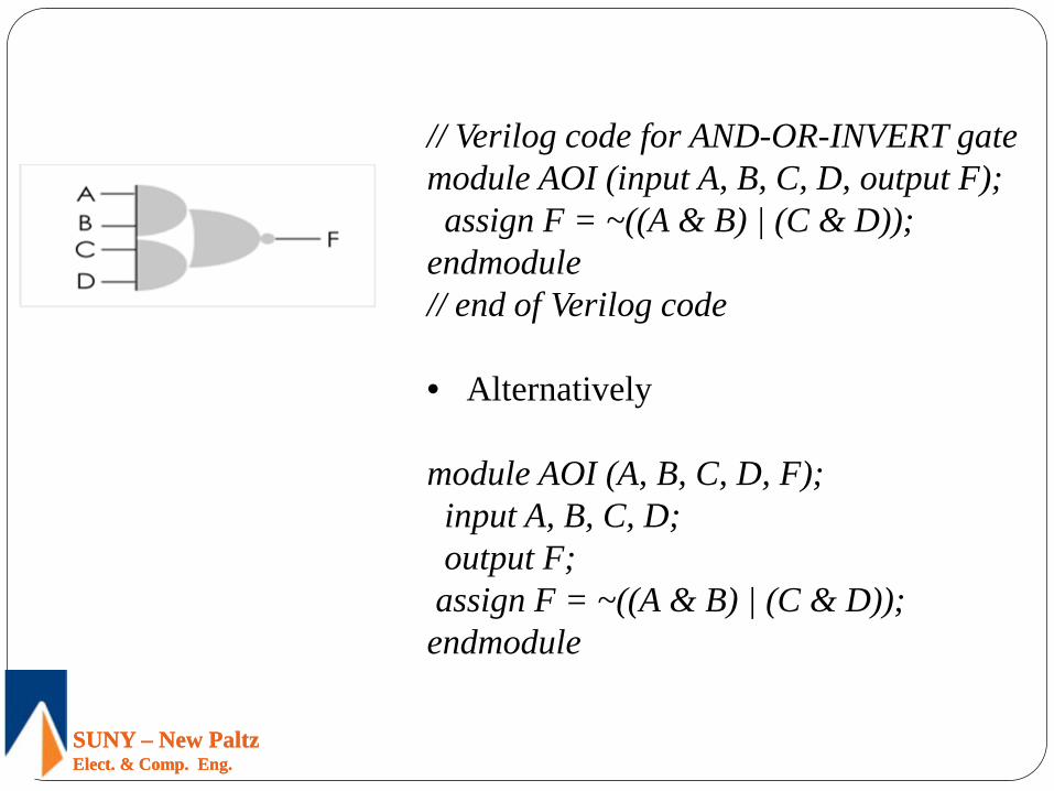
// Verilog code for AND-OR-INVERT gate module AOI (input A, B, C, D, output F); assign F = ~((A & B) | (C & D)); endmodule // end of Verilog code • Alternatively module AOI (A, B, C, D, F); input A, B, C, D; output F; assign F = ~((A & B) | (C & D)); endmodule
SUNY – New Paltz Elect. & Comp. Eng. SUNY – New Paltz Elect. & Comp. Eng.
Lexical Convention Comment // to the end of the line. /* to */ across several lines Keywords are lower case letter. the language is case sensitive Numbers are specified in the traditional form or below . <size><base format><number>
Size: contains decimal digitals that specify the size of the constant in the number of bits.
Base format: is the single character ‘ followed by one of the following characters b(binary),d(decimal),o(octal),h(hex).
Number: legal digital.
SUNY – New Paltz Elect. & Comp. Eng. SUNY – New Paltz Elect. & Comp. Eng.
Example & Lexical Convention
347 // decimal number 347 3’d347 // 3-digit decimal number 347 4’b101 // 4- bit binary number 0101 2’o12 // 2-digit octal number 5’h87f7 // 5-digit hex number 087f7 String in double quotes: “ this is a introduction” Operator are one, two, or three characters and are used in the
expressions. just like C++. Identifier: specified by a letter or underscore followed by more
letter or digits, or signs.
SUNY – New Paltz Elect. & Comp. Eng. SUNY – New Paltz Elect. & Comp. Eng.
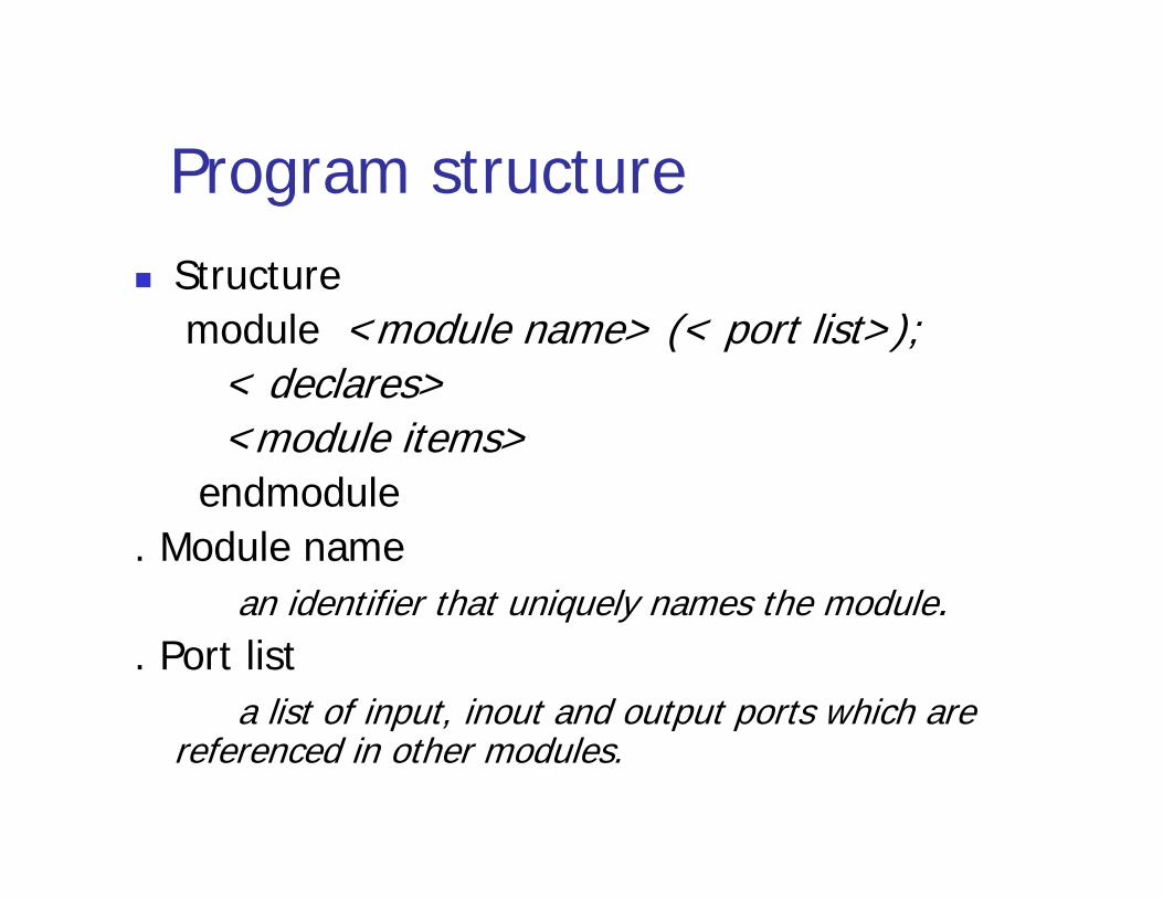
Program Structure Structure module <module name> (< port list>); < declares> <module items> endmodule Module name an identifier that uniquely names the module. Port list a list of input, inout and output ports which are referenced
in other modules.
SUNY – New Paltz Elect. & Comp. Eng. SUNY – New Paltz Elect. & Comp. Eng.
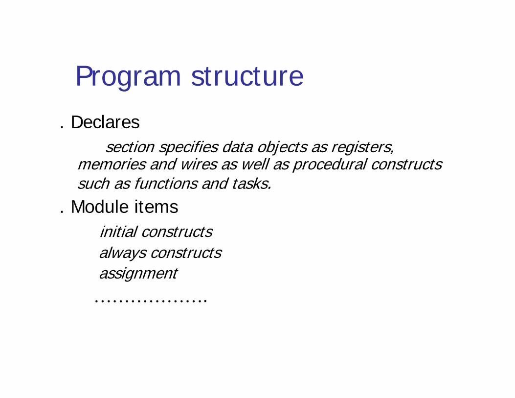
Declares section specifies data objects as registers, memories and wires
as well as procedural constructs such as functions and tasks. Module items initial constructs always constructs assignment ……………….

SUNY – New Paltz Elect. & Comp. Eng. SUNY – New Paltz Elect. & Comp. Eng.
Verilog wire //A Verilog wire represents an electrical connection. //Verilog: Internal signals of an AOI gate module // Verilog code for AND-OR-INVERT gate module AOI (input A, B, C, D, output F); wire F; // the default wire AB, CD, O; // necessary assign AB = A & B; assign CD = C & D; assign O = AB | CD; assign F = ~O; endmodule // end of Verilog code
SUNY – New Paltz Elect. & Comp. Eng. SUNY – New Paltz Elect. & Comp. Eng.
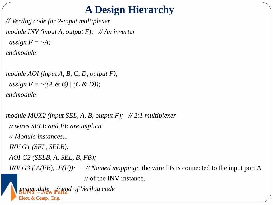
A Design Hierarchy // Verilog code for 2-input multiplexer module INV (input A, output F); // An inverter assign F = ~A; endmodule module AOI (input A, B, C, D, output F); assign F = ~((A & B) | (C & D)); endmodule module MUX2 (input SEL, A, B, output F); // 2:1 multiplexer // wires SELB and FB are implicit // Module instances... INV G1 (SEL, SELB); AOI G2 (SELB, A, SEL, B, FB); INV G3 (.A(FB), .F(F)); // Named mapping; the wire FB is connected to the input port A // of the INV instance. endmodule // end of Verilog code
SUNY – New Paltz Elect. & Comp. Eng. SUNY – New Paltz Elect. & Comp. Eng.
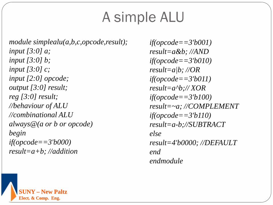
A simple ALU module simplealu(a,b,c,opcode,result); input [3:0] a; input [3:0] b; input [3:0] c; input [2:0] opcode; output [3:0] result; reg [3:0] result; //behaviour of ALU //combinational ALU always@(a or b or opcode) begin if(opcode==3'b000) result=a+b; //addition
if(opcode==3'b001) result=a&b; //AND if(opcode==3'b010) result=a|b; //OR if(opcode==3'b011) result=a^b;// XOR if(opcode==3'b100) result=~a; //COMPLEMENT if(opcode==3'b110) result=a-b;//SUBTRACT else result=4'b0000; //DEFAULT end endmodule
SUNY – New Paltz Elect. & Comp. Eng. SUNY – New Paltz Elect. & Comp. Eng.
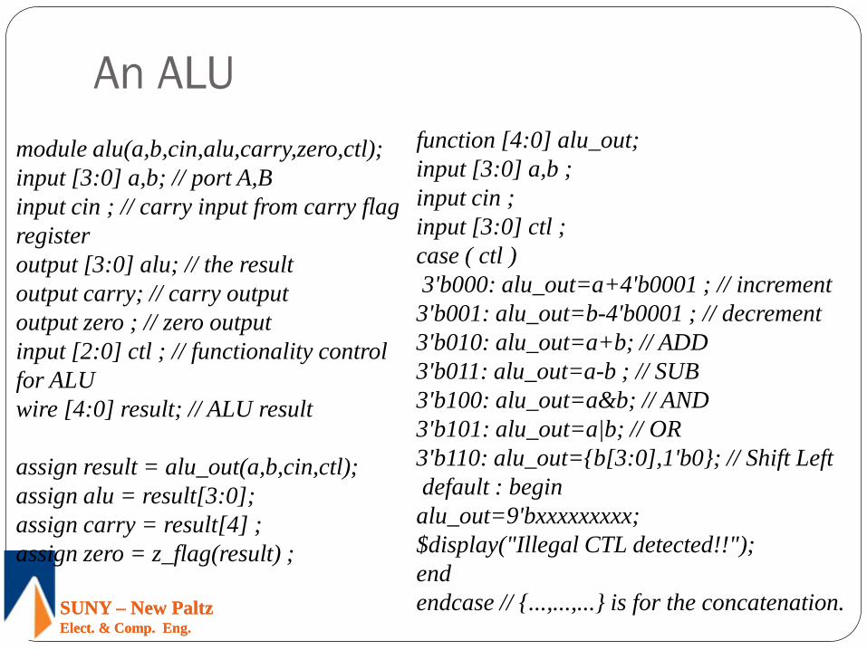
An ALU module alu(a,b,cin,alu,carry,zero,ctl); input [3:0] a,b; // port A,B input cin ; // carry input from carry flag register output [3:0] alu; // the result output carry; // carry output output zero ; // zero output input [2:0] ctl ; // functionality control for ALU wire [4:0] result; // ALU result assign result = alu_out(a,b,cin,ctl); assign alu = result[3:0]; assign carry = result[4] ; assign zero = z_flag(result) ;
function [4:0] alu_out; input [3:0] a,b ; input cin ; input [3:0] ctl ; case ( ctl ) 3'b000: alu_out=a+4'b0001 ; // increment 3'b001: alu_out=b-4'b0001 ; // decrement 3'b010: alu_out=a+b; // ADD 3'b011: alu_out=a-b ; // SUB 3'b100: alu_out=a&b; // AND 3'b101: alu_out=a|b; // OR 3'b110: alu_out={b[3:0],1'b0}; // Shift Left default : begin alu_out=9'bxxxxxxxxx; $display("Illegal CTL detected!!"); end endcase // {...,...,...} is for the concatenation.
SUNY – New Paltz Elect. & Comp. Eng. SUNY – New Paltz Elect. & Comp. Eng.
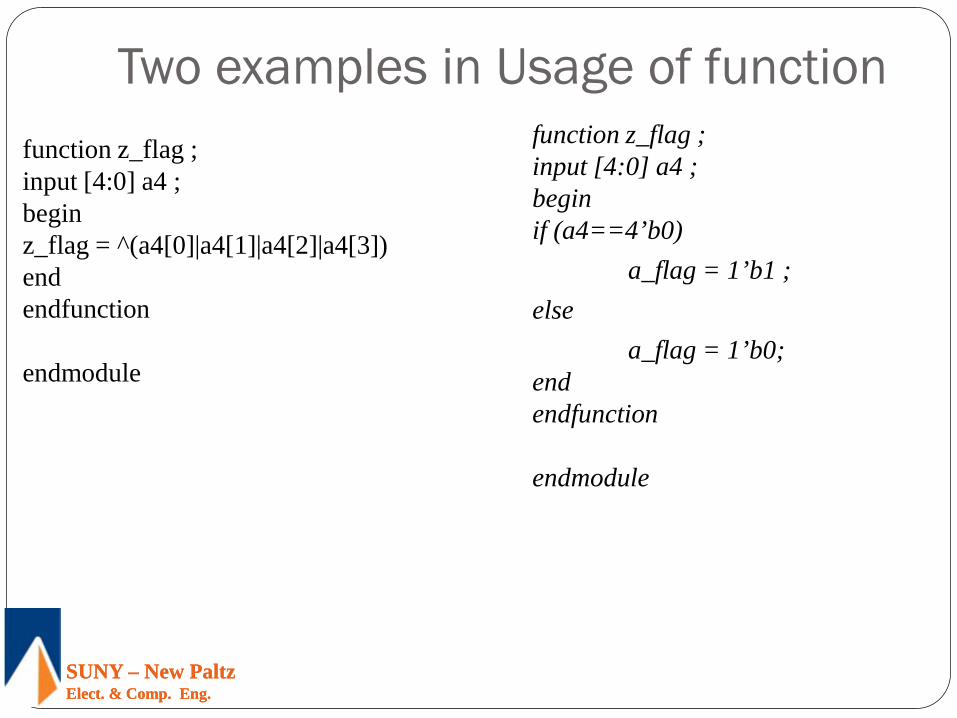
Two examples in Usage of function function z_flag ; input [4:0] a4 ; begin z_flag = ^(a4[0]|a4[1]|a4[2]|a4[3]) end endfunction endmodule
function z_flag ; input [4:0] a4 ; begin if (a4==4’b0) a_flag = 1’b1 ; else a_flag = 1’b0; end endfunction endmodule
Tutorial on Verilog HDL
HDLHardware Description Languages
Widely used in logic designVerilog and VHDL
Describe hardware using codeDocument logic functionsSimulate logic before buildingSynthesize code into gates and layout
Requires a library of standard cells
VerilogVerilog is one of the two major Hardware Description Languages(HDL) used by hardware designers in industry and academia.VHDL is another oneVerilog is easier to learn and use than VHDLVerilog HDL allows a hardware designer to describer designs at a high level of abstraction such as at the architectural or behavioral level as well as the lower implementation levels (i.e., gate and switch levels).
Why use Verilog HDLDigital system are highly complex.Verilog language provides the digital designer a software platform.Verilog allows user to express their design with behavioral constructs.A program tool can convert the Verilogprogram to a description that was used to make chip, like VLSI.
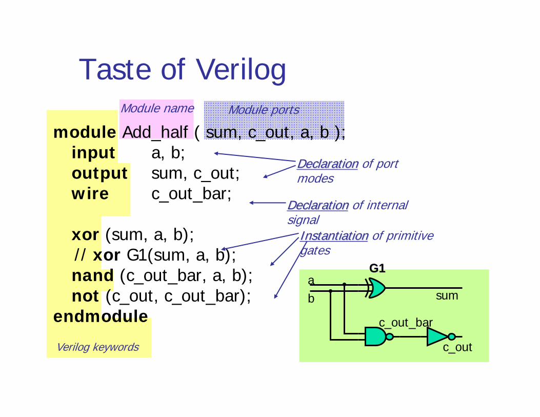
Module portsModule name
Verilog keywords
Taste of Verilog
module Add_half ( sum, c_out, a, b );input a, b;output sum, c_out;wire c_out_bar;
xor (sum, a, b);// xor G1(sum, a, b);nand (c_out_bar, a, b);not (c_out, c_out_bar);
endmodule
DeclarationDeclaration of port modes
DeclarationDeclaration of internal signal
InstantiationInstantiation of primitive gates
c_out
ab sum
c_out_bar
G1G1
Lexical Convention
Lexical convention are close to C++.Comment// to the end of the line./* to */ across several lines
. Keywords are lower case letter.the language is case sensitive
Lexical ConventionNumbers are specified in the traditional form or below .<size><base format><number>
Size: contains decimal digitals that specify the size of the constant in the number of bits.Base format: is the single character ‘ followed by one of the following characters b(binary),d(decimal),o(octal),h(hex).Number: legal digital.
Lexical ConventionExample :
347 // decimal number4’b101 // 4- bit binary number 01012’o12 // 2-bit octal number5’h87f7 // 5-bit hex number h87f72’d83 // 2-bit decimal number
String in double quotes“ this is a introduction”

Lexical ConventionOperator are one, two, or three characters and are used in the expressions.
just like C++.Identifier: specified by a letter or underscore followed by more letter or digits, or signs.
Program structureStructuremodule <module name> (< port list>);
< declares><module items>
endmodule. Module name
an identifier that uniquely names the module.. Port list
a list of input, inout and output ports which are referenced in other modules.
Program structure. Declares
section specifies data objects as registers, memories and wires as well as procedural constructs such as functions and tasks.
. Module items initial constructsalways constructsassignment……………….

Test Module structure
module <test module name> ;// Data type declaration. // Data type declaration. Inputs declared as Inputs declared as regreg and and outputs declared as outputs declared as wirewire// Instantiate module ( call the module that is// Instantiate module ( call the module that is going going to be tested)to be tested)// Apply the stimulus// Apply the stimulus// Display results// Display results
endmodule
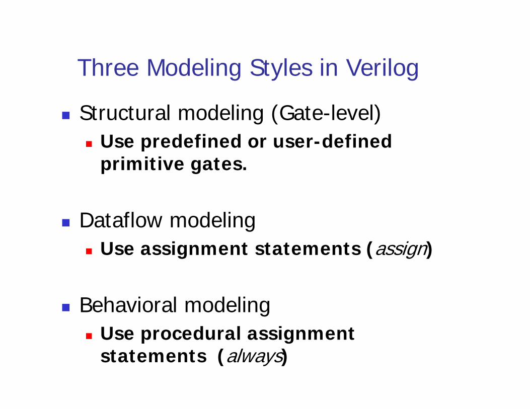
Three Modeling Styles in Verilog
Structural modeling (Gate-level) Use predefined or user-defined primitive gates.
Dataflow modelingUse assignment statements (assign)
Behavioral modelingUse procedural assignment statements (always)
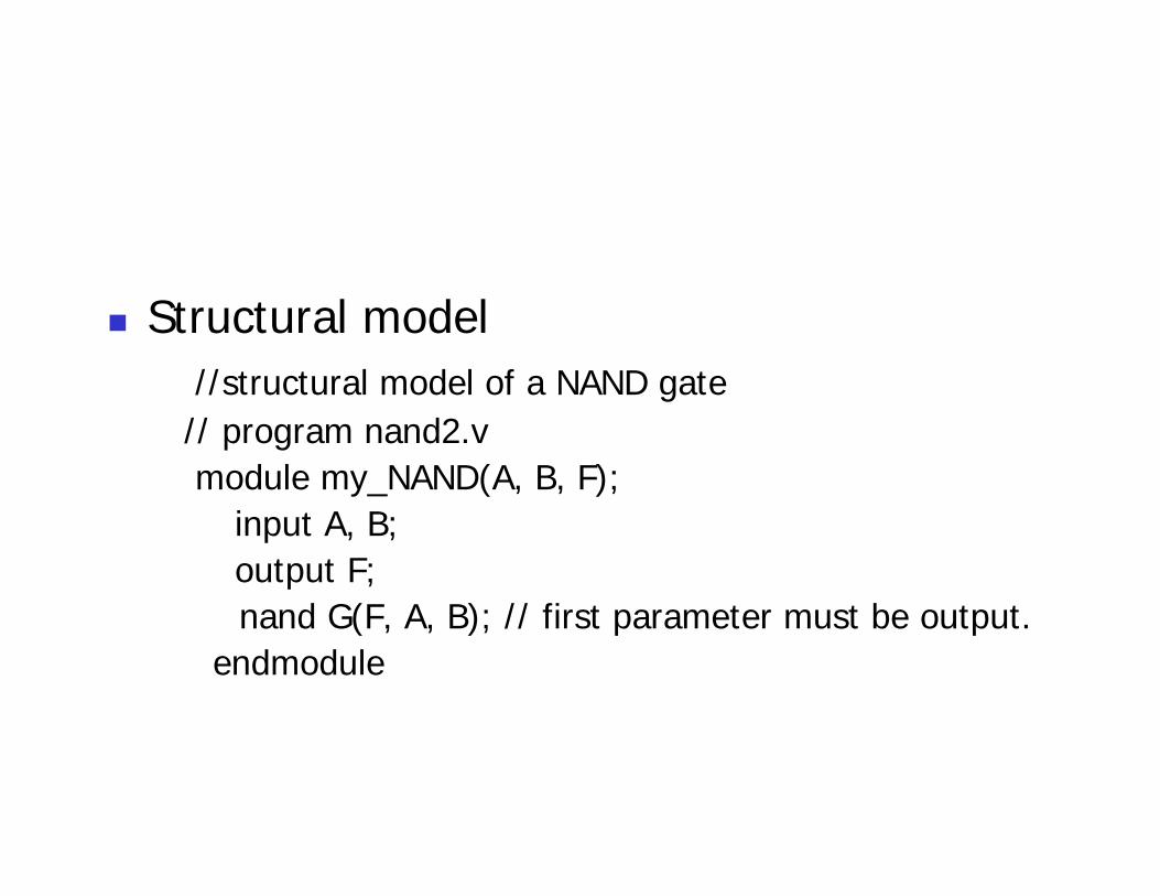
Structural model//structural model of a NAND gate// program nand2.vmodule my_NAND(A, B, F);
input A, B;output F;nand G(F, A, B); // first parameter must be output.
endmodule

Example of gate NAND
module test_my_nand;// Test bench to test nandreg A, B; wire F; my_NAND test_my_nand(A, B, F); // instantiate my_NAND.initial begin // apply the stimulus, test data
A = 1'b0; B = 1'b0;#100 A = 1'b1; // delay one simulation cycle, then change A=>1.
#100 B = 1'b1;#100 A = 1'b0;
endinitial #500 $finish;begin // setup monitoring
//$monitor("Time=%0d a=%b b=%b out1=%b", $time, A, B, F);//#500 $finish;
endendmodule
Test bench module test_nand for the nand1.v
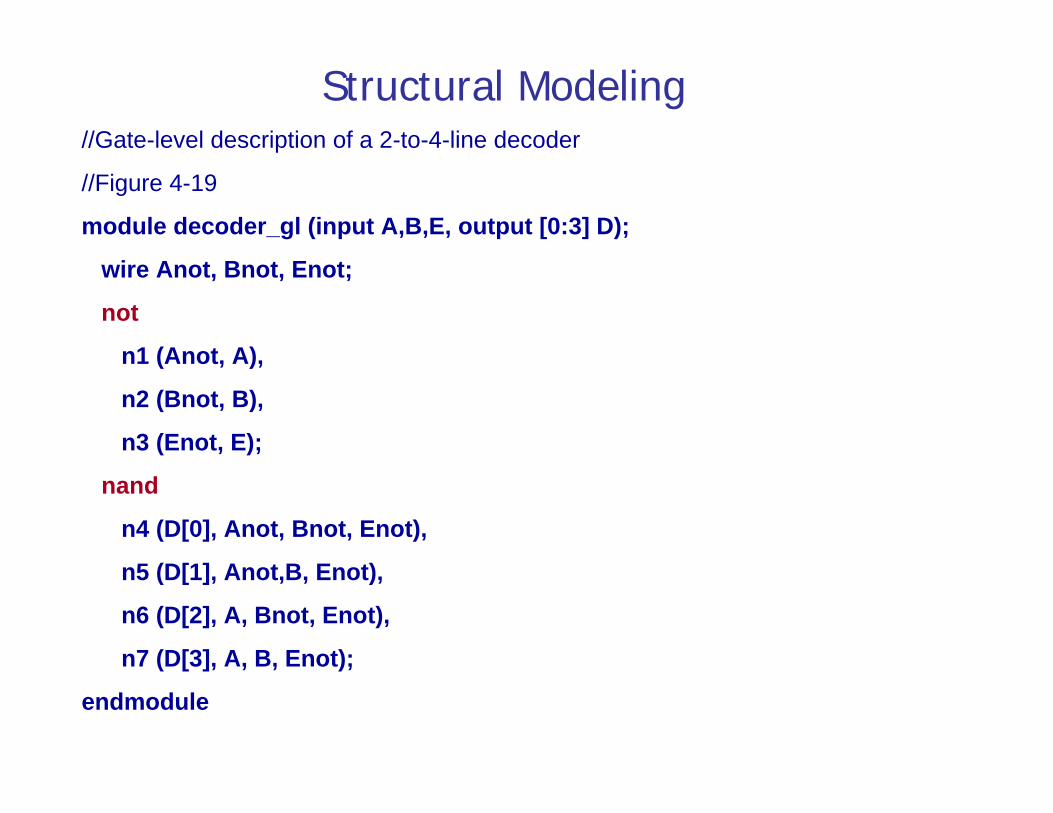
//Gate-level description of a 2-to-4-line decoder
//Figure 4-19
module decoder_gl (input A,B,E, output [0:3] D);
wire Anot, Bnot, Enot;
not
n1 (Anot, A),
n2 (Bnot, B),
n3 (Enot, E);
nand
n4 (D[0], Anot, Bnot, Enot),
n5 (D[1], Anot,B, Enot),
n6 (D[2], A, Bnot, Enot),
n7 (D[3], A, B, Enot);
endmodule
Structural Modeling
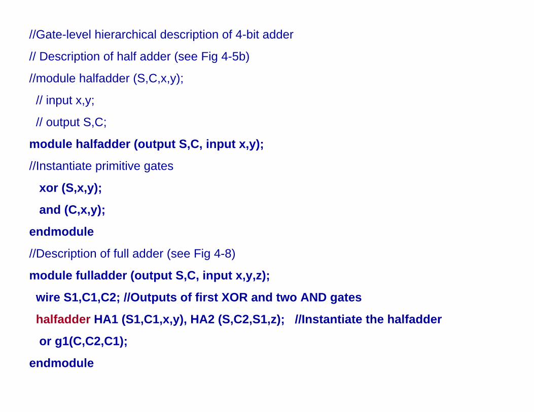
//Gate-level hierarchical description of 4-bit adder
// Description of half adder (see Fig 4-5b)
//module halfadder (S,C,x,y);
// input x,y;
// output S,C;
module halfadder (output S,C, input x,y);
//Instantiate primitive gates
xor (S,x,y);
and (C,x,y);
endmodule
//Description of full adder (see Fig 4-8)
module fulladder (output S,C, input x,y,z);
wire S1,C1,C2; //Outputs of first XOR and two AND gates
halfadder HA1 (S1,C1,x,y), HA2 (S,C2,S1,z); //Instantiate the halfadder
or g1(C,C2,C1);
endmodule
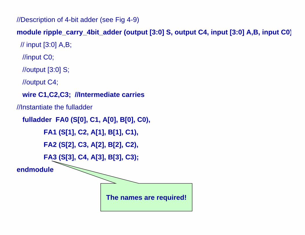
//Description of 4-bit adder (see Fig 4-9)
module ripple_carry_4bit_adder (output [3:0] S, output C4, input [3:0] A,B, input C0)
// input [3:0] A,B;
//input C0;
//output [3:0] S;
//output C4;
wire C1,C2,C3; //Intermediate carries
//Instantiate the fulladder
fulladder FA0 (S[0], C1, A[0], B[0], C0),
FA1 (S[1], C2, A[1], B[1], C1),
FA2 (S[2], C3, A[2], B[2], C2),
FA3 (S[3], C4, A[3], B[3], C3);
endmodule
The names are required!
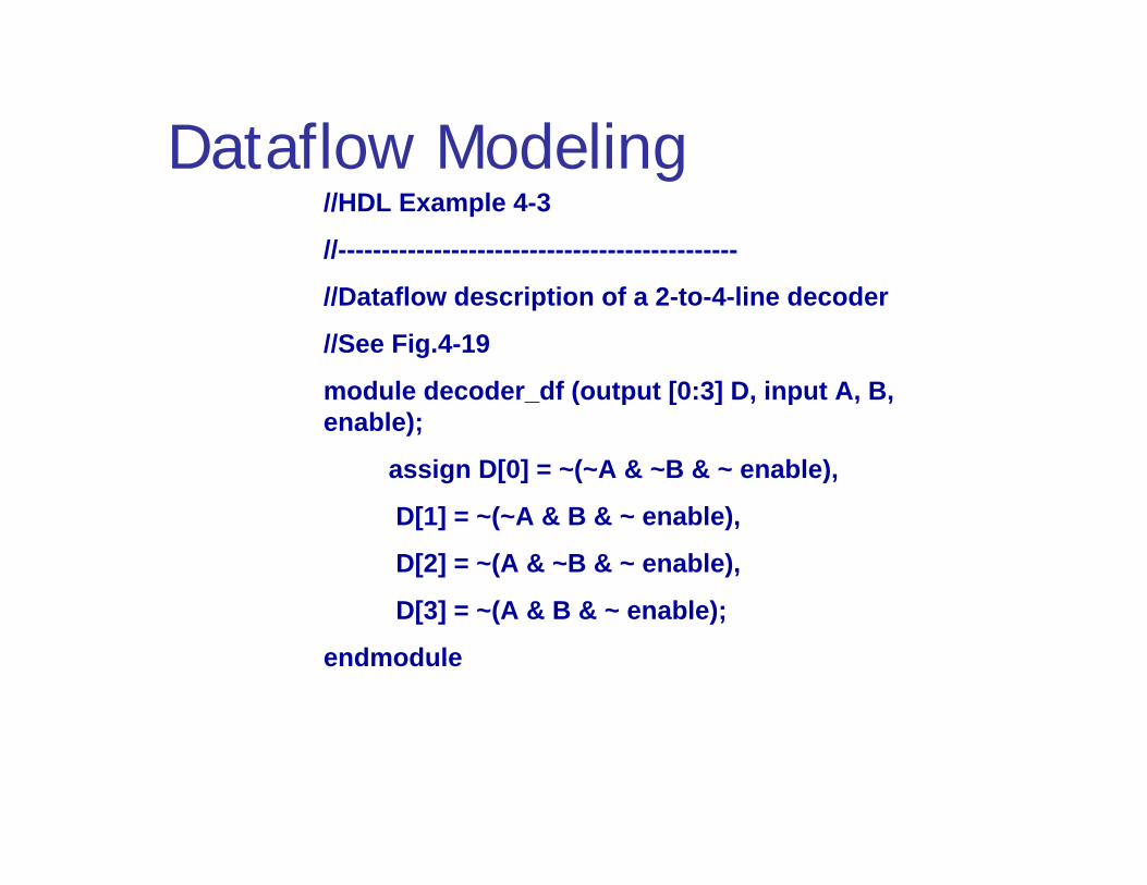
Dataflow Modeling//HDL Example 4-3
//----------------------------------------------
//Dataflow description of a 2-to-4-line decoder
//See Fig.4-19
module decoder_df (output [0:3] D, input A, B, enable);
assign D[0] = ~(~A & ~B & ~ enable),
D[1] = ~(~A & B & ~ enable),
D[2] = ~(A & ~B & ~ enable),
D[3] = ~(A & B & ~ enable);
endmodule
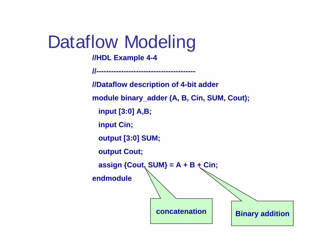
Dataflow Modeling//HDL Example 4-4
//----------------------------------------
//Dataflow description of 4-bit adder
module binary_adder (A, B, Cin, SUM, Cout);
input [3:0] A,B;
input Cin;
output [3:0] SUM;
output Cout;
assign {Cout, SUM} = A + B + Cin;
endmodule
concatenation Binary addition
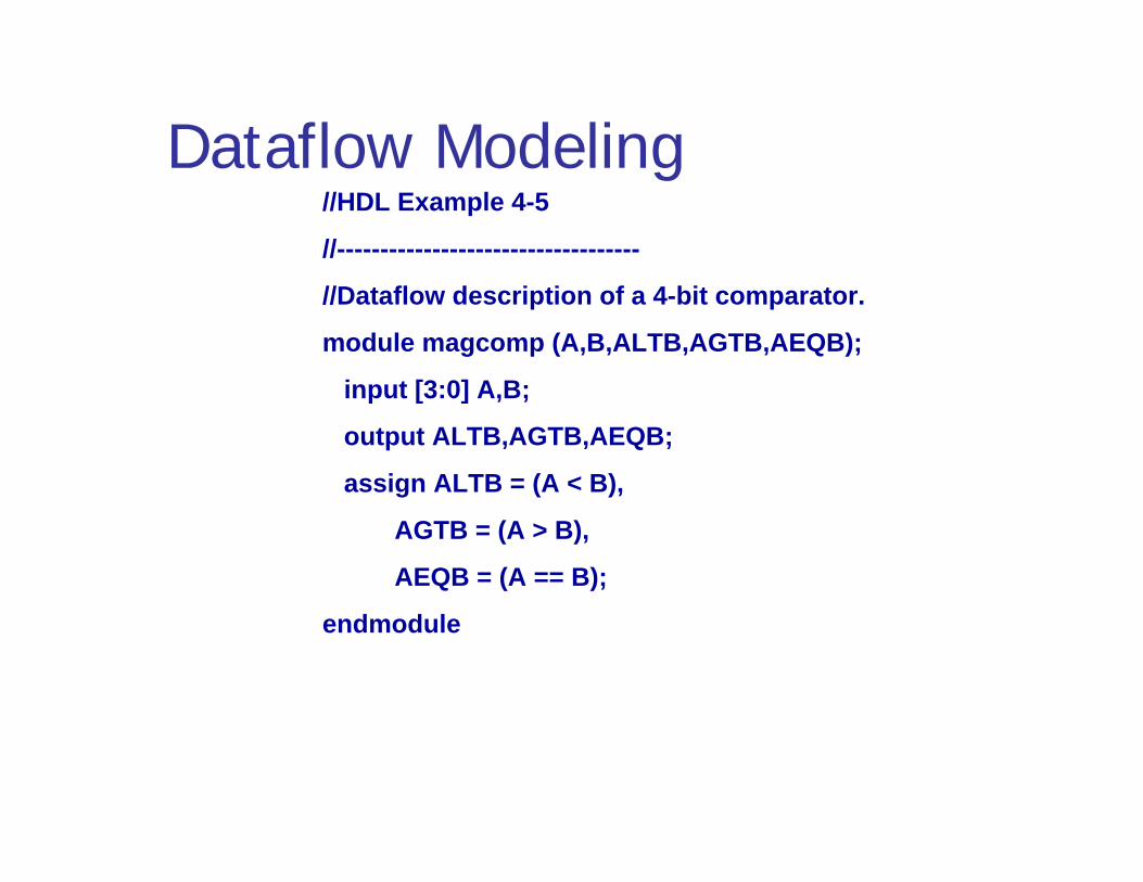
Dataflow Modeling//HDL Example 4-5
//-----------------------------------
//Dataflow description of a 4-bit comparator.
module magcomp (A,B,ALTB,AGTB,AEQB);
input [3:0] A,B;
output ALTB,AGTB,AEQB;
assign ALTB = (A < B),
AGTB = (A > B),
AEQB = (A == B);
endmodule
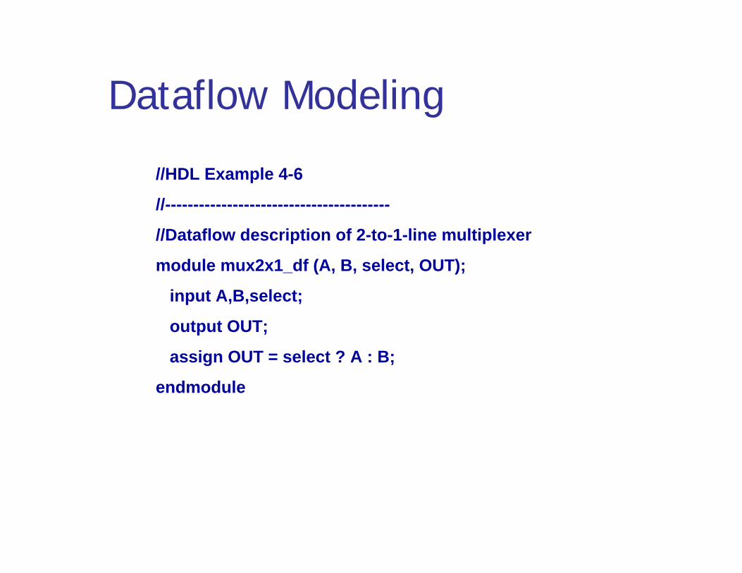
Dataflow Modeling
//HDL Example 4-6
//----------------------------------------
//Dataflow description of 2-to-1-line multiplexer
module mux2x1_df (A, B, select, OUT);
input A,B,select;
output OUT;
assign OUT = select ? A : B;
endmodule
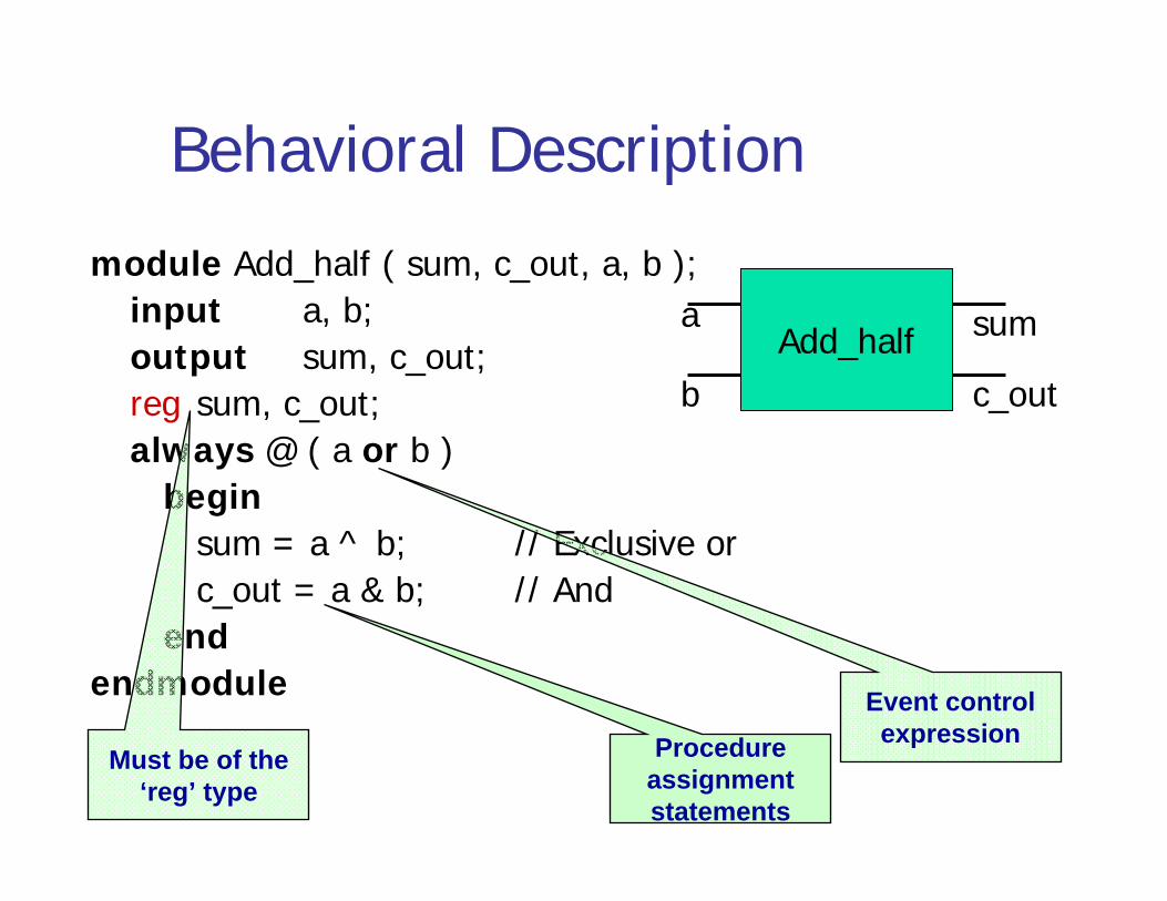
Behavioral Description
module Add_half ( sum, c_out, a, b );input a, b;output sum, c_out;reg sum, c_out;always @ ( a or b )
beginsum = a ^ b; // Exclusive orc_out = a & b; // And
endendmodule
a
bAdd_half sum
c_out
Event control expressionProcedure
assignment statements
Must be of the ‘reg’ type
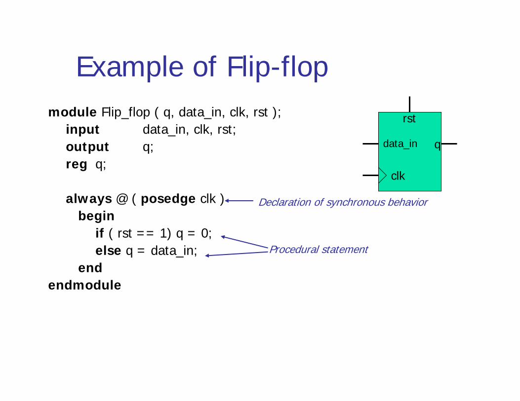
Example of Flip-flopmodule Flip_flop ( q, data_in, clk, rst );
input data_in, clk, rst;output q;reg q;
always @ ( posedge clk )begin
if ( rst == 1) q = 0;else q = data_in;
endendmodule
data_in q
rst
clk
Declaration of synchronous behavior
Procedural statement