Embed Size (px)
Citation preview

754 IEEE TRANSACTIONS ON COMMUNICATIONS, VOL. 50, NO. 5, MAY 2002
Turbo Equalization: Principles and New ResultsMichael Tüchler, Ralf Koetter, and Andrew C. Singer
Abstract—We study the turbo equalization approach to codeddata transmission over channels with intersymbol interference.In the original system invented by Douillard et al., the data areprotected by a convolutional code and the receiver consists of twotrellis-based detectors, one for the channel (the equalizer) and onefor the code (the decoder). It has been shown that iterating equal-ization and decoding tasks can yield tremendous improvementsin bit error rate. We introduce new approaches to combiningequalization based on linear filtering with decoding. Throughsimulation and analytical results, we show that the performanceof the new approaches is similar to the trellis-based receiver, whileproviding large savings in computational complexity. Moreover,this paper provides an overview of the design alternatives forturbo equalization with given system parameters, such as thechannel response or the signal-to-noise ratio.
Index Terms—Decoding, equalization, intersymbol interference,iterative methods, turbo equalization.
I. INTRODUCTION
M ANY practical communication systems encounter theproblem of data transmission over a channel with inter-
symbol interference (ISI). To protect the integrity of the datato be transmitted, a controlled amount of redundancy is added(encoding) using an error correction code (ECC). In this paper,we assume a coherent, symbol-spaced receiver front-end andprecise knowledge of the signal phase and symbol timing, suchthat the channel can be approximated by an equivalent, discrete-time, baseband model, as shown in Fig. 1, where the transmitfilter, the channel, and the receive filter are represented by a dis-crete-timelinear filter, with the finite-length impulse response(FIR)
(1)
of length . The coefficients are assumed to be time-in-variant and known to the receiver.
In a typical implementation of the system of Fig. 1, thereceived symbols are processed with an equalizer or detector tocombat the effects of ISI. The equalizer produces estimates ofthe data and, for complexity reasons, typically consists of linear
Paper approved by W. E. Ryan, the Editor for Modulation, Coding, and Equal-ization of the IEEE Communications Society. Manuscript received September14, 2000; revised June 27, 2001, and October 22, 2001. This work was sup-ported in part by the National Science Foundation under Grant CCR-0092598(CAREER) and Grant CCR-9984515 (CAREER) and the Office Of Naval Re-search under Award N000140110117.
M. Tüchler is with the Institute for Communications Engineering,Technical University of Munich, D-80290 Munich, Germany (e-mail:[email protected]).
R. Koetter and A. C. Singer are with the Department of Electrical andComputer Engineering, University of Illinois at Urbana Champaign, Urbana,IL 61801 USA (e-mail: [email protected]; [email protected]).
Publisher Item Identifier S 0090-6778(02)05108-5.
Fig. 1. Representation of a data transmission system.
processing of the received signal [linear equalizer (LE)] andpossibly past symbol estimates [decision feedback equalizer(DFE)] [1], [2]. The parameters of these filters can be selectedusing a variety of optimization criteria, such as zero forcing(ZF) or minimum mean squared error (MMSE) criteria [1],[2]. Optimal equalization methods for minimizing the bit errorrate (BER) and the sequence error rate are nonlinear and arebased on maximum-likelihood (ML) estimation, which turnsinto maximuma posteriori probability (MAP) estimation inthe presence ofa priori information about the transmitted data.Efficient algorithms exist for MAP/ML sequence estimation,e.g., the Viterbi algorithm (VA) [1], [3], [4], and MAP/MLsymbol estimation, e.g., the BCJR algorithm [5]. We will referto these estimation methods as MAP/ML equalization.
Significant improvements in BER performance are possiblewith coded data transmission using an ECC. Communicatingsoft information between the equalizer and the decoder, insteadof hard information (symbol estimates only), improves the BERperformance but usually requires more complex decoding al-gorithms. State-of-the-art systems for a variety of communica-tion channels employ convolutional codes and ML equalizerstogether with an interleaver after the encoder and a deinterleaverbefore the decoder [6], [7]. Interleaving shuffles symbols withina given time frame or block of data and thus decorrelates errorevents introduced by the equalizer between neighboring sym-bols. These error “bursts” are hard to deal with using a con-volutional decoder alone. Some applications exploit coding toovercome deficiencies of the chosen equalizer, e.g., the use of aDFE and a high-rate code to deal with the effects of error prop-agation [8].
In the receiver, an optimal joint processing of the equaliza-tion and decoding steps is usually impossible due to complexityconsiderations. A number of iterative receiver algorithms repeatthe equalization and decoding tasks on the same set of receiveddata, where feedback information from the decoder is incorpo-rated into the equalization process. This method, called turboequalization, was originally developed for concatenated convo-lutional codes (turbo coding, [9]) and is now adapted to var-ious communication problems, such as trellis coded modulation(TCM) [10], [11] and code division multiple access (CDMA)[12]. We refer to standard references [13]–[15] for an overviewof turbo coding. Turbo equalization systems were first proposedin [16] and further developed in several articles [17], [18]. In
0090-6778/02$17.00 © 2002 IEEE

TÜCHLER et al.: TURBO EQUALIZATION: PRINCIPLES AND NEW RESULTS 755
all these systems, MAP-based techniques, most often a VA pro-ducing soft output information [19], are used exclusively forboth equalization and decoding [16], [17]. The more complexBCJR algorithm [5] was implemented in [17]. Combined turbocoding and equalization [20], [21] includes three or more layers:two or more coding layers as in conventional turbo coding ap-plications and the channel equalizer.
The MAP/ML-based solutions often suffer from highcomputational load for channels with long memory or largeconstellation sizes (expensive equalizer) or convolutionalcodes with long memory (expensive decoder). This situation isexacerbated by the need to perform equalization and decodingseveral times for each block of data. A major research issueis thus the complexity reduction of such iterative algorithms.Ariyavisitakul and Li [22] proposed a joint coding-equalizationapproach, distinct from turbo equalization, working withconvolutional coding and a DFE. Here, within the DFE, softinformation from the DFE forward filter and tentative (hard)decisions from the decoder using the VA are fed back. Wangand Poor [12] proposed a turbo equalization-like system aspart of a multiuser detector for CDMA. This iterative schemeis based on turbo equalization using an LE to reduce ISIand MAP decoding. The MAP equalizer is thus replacedwith an LE, whose filter parameters are updated for everyoutput symbol of the equalizer. In [23], the MAP equalizerin the turbo equalization framework is exchanged with a softinterference canceler based on linear filters with very lowcomputational complexity, whose coefficients are obtainedusing a least-mean-square (LMS)-based update algorithm.This idea is enhanced in [24], where the filter coefficients areobtained using the LMS algorithm to match the output of aMAP equalizer. For varying signal-to-noise ratios (SNRs) andfeedback information constellations, a linear estimate of theMAP equalizer is stored in a table and used for equalizationin the receiver. The approach in [25] is similar to that of [23],but assumes a (known) impulse response of a partial responsechannel occurring in magnetic recording applications. Theequalizer filter output is assigned a reliability measure enablingthe receiver to decide whether the linear algorithm should beused instead of MAP equalization. Another common techniqueto decrease the complexity of the MAP equalizer is to reducethe number of states in the underlying trellis, which was appliedto turbo equalization in [26]. The approaches in [23]–[25] andthose proposed in this paper address a major shortcoming ofthe classical turbo equalization scheme [16]–[18], which isthe exponentially increasing complexity of the equalizer forchannels with a long impulse response or large signal alphabets.We replace the MAP equalizer with an LE and a DFE, wherethe filter parameters are updated using the MMSE criterion.
The paper is organized as follows. A brief definition of acoded data transmission system applying turbo equalization inthe receiver is given in Sections II and III. In Section IV, we de-scribe the general structure of a soft-in soft-out (SISO) equalizerbased on MMSE equalization and derive four different imple-mentations of this general approach using an LE or a DFE. Com-plexity considerations are explored in Section V. In Section VI,the two receiver components and the overall system are ana-
Fig. 2. Transmitter section of the data transmission system.
lyzed yielding estimates of the BER performance of the systemand suggestions on how to select appropriate codes and SISOequalizers. These results are verified and compared to existingsolutions [12], [16]–[18], [23]–[25] in Section VII and summa-rized in Section VIII.
II. NOTATION AND SYSTEM DEFINITION
To simplify the derivations, all systems to be investigated con-tain the same transmitter depicted together with the ISI channelin Fig. 2. The (binary) data is encoded with a (binary) convolu-tional encoder yielding the code symbols, which are mappedto the alphabet of the signal constellation. In this paper, forsimplicity we assume binary phase shift keying (BPSK), i.e.,
, and that the channel impulse response coeffi-cients and the noise samples are real valued. A frame-work to develop algorithms for higher order constellations andcomplex-valued and is presented in [27].
The transmission and receiving tasks are applied to blocksof data bits of length . They are encoded to
code symbols , ,, where is the code rate and is
any overhead introduced by the encoder, e.g., a termination se-quence. The interleaver permutes theand outputs sym-bols , , , to be transmitted over the ISIchannel. This operation is denoted , where is afixed random permutation on elements. For more informa-tion on (see, for example, [15]). The permutation ,the deinterleaver, reverses the operation. The noise is mod-eled as additive white Gaussian noise (AWGN), i.e., the noisesamples are independent and identically distributed (i.i.d.)with normal probability density function (pdf)
(2)
and independent of the data, where . Given(1), the receiver input is given by
Before proceeding with a description of the different methodsfor turbo equalization, some frequently used notation is intro-duced. Vectors are written in bold letters and are considered tobe column vectors. Matrices are specified by bold capital let-ters. Time-varying quantities are augmented with a time index
as the subscript. The matrix contains all zeros,and contains all ones. is the identity matrix. Theoperator is the expectation with respect to the joint pdfof and . The covariance operator is given by
, where is the Hermitian oper-

756 IEEE TRANSACTIONS ON COMMUNICATIONS, VOL. 50, NO. 5, MAY 2002
Fig. 3. A receiver performing turbo equalization.
ator. The -value operator is applied to quantitiesand is given by
i.e., the log likelihood ratio (LLR). The operator to beapplied to a length vector returns an square matrix withthe vector elements along the main diagonal.
III. B ASIC PRINCIPLE OFTURBO EQUALIZATION
Fig. 3 depicts the receiver structure for turbo equalization pio-neered in [16]. All other approaches presented here use the samestructure and vary only in the type of equalizer. For decoding,we consider only the BER-optimal MAP approach. The MAPequalizer suitable for turbo equalization, which was shown toperform best in simulations among the trellis-based detectionschemes [17], computes thea posterioriprobabilities (APP’s),
, , given received symbols, , and outputs thea posterioriLLR minus
thea priori LLR
(3)
Thea priori LLR, which is , represents prior informationon the occurrence probability of and is provided by the de-coder. For the initial equalization step, noa priori informationis available and hence we have , . We empha-size that is independent of . This and the conceptof treating feedback asa priori information are the two essen-tial features of any system applying the turbo principle [13] andturbo equalization in particular [16], [17]. The MAP decodercomputes the APPs , ,given code bit LLRs , , and outputsthe difference
where the equalizer output is considered to bea prioriLLR for the decoder. The interleaver and the deinter-leaver provide the correct ordering of the LLRs
and , which are input tothe equalizer and decoder, respectively. The MAP decoder alsocomputes the data bit estimates
(4)
Fig. 4. A SISO equalizer based on MMSE equalization.
Applying the turbo principle, after an initial detection of a blockof received symbols, blockwise decoding and equalization oper-ations are performed on the same set of received data. A suitablychosen termination criterion stops the iterative process.
IV. TURBO EQUALIZATION USING MMSE EQUALIZATION
The MAP equalizer in Fig. 3 can be replaced with the SISOequalizer shown in Fig. 4. The depicted structure leads to arather general class of SISO equalizers consisting of an MMSEequalizer, which computes estimatesof the transmitted sym-bols from the received symbols by minimizing the costfunction . We will apply linear and nonlinear (in-cluding decision feedback) MMSE equalizers. We furthermoreshow that some instances of the SISO equalizer algorithms re-cover algorithms by Glavieuxet al.[23] and Wu and Cioffi [25].The SISO equalizer output is obtained using the esti-mate
(5)
instead of , , which requires the knowledge ofthe distribution of conditioned on ,
.To perform MMSE estimation, the statistics and
of the symbols are required. Usually, theare assumed to be equiprobable and i.i.d., which corresponds
to , , and yields and . For general(the are not equiprobable), and are ob-
tained as
After MMSE equalization, we assume that the pdfs
, , are Gaussian with the parameters
and [12]
(6)
This assumption tremendously simplifies the computation ofthe SISO equalizer output LLR . We emphasize that
should not depend on the particulara priori LLR. Therefore, we require that does not depend on, which affects the derivation of the MMSE equalization
algorithms.
TÜCHLER et al.: TURBO EQUALIZATION: PRINCIPLES AND NEW RESULTS 757
A. Turbo Equalization Using Linear MMSE Equalization
1) Exact Implementation:The MMSE equalizer for thisnovel approach is an LE consisting of a lengthfilter withtime-varyingcoefficients , ,where , which are defined by thelinear MMSE estimate [28] of given the observation
:
(7)
For data transmission over an ISI channel, this becomes
where is the channel convolution matrix
...
and
However, depends on via and . In order thatbe independent of , we set to 0 while computing
, yielding and . This changes (7) to
Writing the MMSE LE output as
where , the vector of the coefficients
is consequently set to
This yields the final expression ,from which the statistics and of are computed
The output LLR follows as
(8)
When , , e.g., for the initial equalization step,we have and , , yielding a time-invariantcoefficient vector (NA stands for noa priori infor-mation), the usual MMSE LE solution [1]
The corresponding output LLR is given by
(9)
2) Approximate Implementation I:Computing for eachtime step causes a high computational load for computing
, since an matrix has to be inverted for each. Arecursive algorithm to compute from devised in [27] re-duces this load tremendously. A further reduction is possible byusing time-invariant coefficients. We propose a low-complexityalternative, motivated as an approximation to the exact MMSEsolution, which uses the time-invariant coefficient vectorto compute given a general
The use of this approximation will be justified by the excellentcomplexity/performance tradeoff shown in Sections V and VI.Given a set of general, nonzero, , while the MMSE-op-timal coefficients must vary with , if we restrict complexitysuch that the filter coefficients are time-invariant, then after sub-tracting the nonzero means, this set of coefficients can be viewedas MMSE optimal by simply ignoring (i.e., setting to zero) the
. From the statistics
for this approach, the output LLR is given by
Computing for each is computationally expensive. Apossible simplification is to approximate with the time
average
which can be further simplified to
(10)
using the approximation. Simulation results not shown in this paper
reveal that using instead of does not sacrificemuch performance.

758 IEEE TRANSACTIONS ON COMMUNICATIONS, VOL. 50, NO. 5, MAY 2002
When , , the exact (Section IB-A-1) and theapproximate implementation I of the MMSE LE are identical,yielding the same output LLR .
3) Approximate Implementation II:Another way to yield atime-invariant coefficient vector is to let , , i.e.,for perfecta priori information, yielding and
which is the matched filter response to the channel impulse re-sponse normalized by , where is the
energy of the channel. The estimatesare computed using given general as follows:
(11)
yielding the statistics
and the output LLR
It turns out that is identical to that for the linear SISO equal-izer in [23] (in case the assumption , , actuallyholds) and [25]. Thus, the algorithms in [23] and [25] are in-stances of the MMSE LE derived in Section IV-A1 under theconstraint that , . As in Section IV-A3, thevariance can be approximated using the time average
(12)
When , , for which this approach, as shown later,is certainly not suited, the output LLR becomes
B. Turbo Equalization Using MMSE Decision FeedbackEqualization
The MMSE equalizer for the second novel approach intro-duced in this paper is a DFE consisting of a lengthfeedfor-ward filter with time-varyingcoefficients ,
, , and a strictly causal lengthfeedback filter withtime-varyingcoefficients ,
. It is natural to address the postcursor ISI with the
feedback filter and the precursor ISI with the feedforward filteryielding the choice
for the filter length parameters [1]. A general expression for theMMSE DFE output is therefore
(13)
where the are past decided estimates obtained using anappropriate decision function, e.g.,
for BPSK. We assume that the DFE is error-free, i.e.,, . Using the relation ,
, between the feedback coefficients and thefeedforward coefficients [1], which also holds in the pres-ence ofa priori information [29], the output equation(13) becomes
where is the channel con-
volution matrix, ,
. Applying (7), i.e.,, we find
where the zero row in follows because the transmitted sym-bols , , are assumed to be knowndue to the available decided estimates yielding .The derivation of the MMSE DFE is similar to MMSE estima-tion using (7) given the observation [29]
As in Section IV-A1, to ensure that is independent from, we replace and with 0 and 1, respectively, while
computing :
With the final expressions for the feedforward filter coefficients,, and the MMSE
estimate, , the statistics

TÜCHLER et al.: TURBO EQUALIZATION: PRINCIPLES AND NEW RESULTS 759
TABLE INUMBER OF REQUIRED OPERATIONSPER RECEIVED SYMBOL PER ITERATION USING VARYING SISO EQUALIZATION ALGORITHMS.M : CHANNEL IMPULSE
RESPONSELENGTH; N : EQUALIZER FILTER LENGTH; 2 : ALPHABET SIZE OF THE SIGNAL CONSTELLATION
and the output LLR
(14)
can be computed as in Section IV-A1.When , , is time invariant and equal to the
usual MMSE DFE solution [1]
The corresponding output LLR is given by
A recursive algorithm to efficiently compute fromis given in [29]. It is also possible to derive approximate im-plementations similar to the approaches in Sections IV-A2 andIV-Q3. However, the resulting suboptimal algorithms exhibit in-ferior performance to the exact implementation [29], which inturn is inferior to the LE-based methods (see Section VII). Wetherefore omit the corresponding derivations here.
V. COMPLEXITY COMPARISON
An important aspect of these SISO equalizer algorithms istheir computational complexity. We consider the MAP equal-izer, the exact MMSE LE (Section IV-A1), the approximateMMSE LE (I) (Section IV-A2) and (II) (Section IV-A3), andthe MMSE DFE (Section IV-B) for comparison.
We assume that the statistics and of are availablefor all and do not consider the computation of [bothmappings and strongly dependon ]. Any overhead due to initialization (one-time operationsfor all iterations), e.g., to compute , is neglected. All quan-tities are assumed to be complex for this comparison. Table Ishows the required number of real multiplications and additionsper received symbol per iteration, given generala priori in-formation . The numbers for the MMSE-based ap-proaches follow from the detailed algorithm derivations in [29].The MAP equalizer uses the BCJR algorithm [5], where we con-sidered only the computation of the path metrics (thequantity)for all trellis sections and the-, -recursions. Efficient imple-mentations of the BCJR algorithm in the context of the turboprinciple are presented, for example, in [13] and [17]. The al-gorithms for the approximate MMSE LE’s (I) and (II) can beimplemented in the frequency domain [30], which further de-creases the computational load for specific systems.
Fig. 5. The two basic receiver components.
VI. A NALYSIS
A. The EXIT Chart
We describe in this paper an analysis tool called an EXITchart to compare the performance of the approaches describedin Section IV and to ease the selection of system parameters,such as the generator of the convolutional code or the equalizerfilter lengths.
A large body of research has been undertaken to provide toolsfor choosing design options for turbo codes, e.g., by analyzingthe effects of the interleaver and bounds on the BER [31], [32].Another analysis approach is to consider the turbo decoder asa high-dimensional nonlinear dynamic system [33], [34] whoseconvergence behavior can be characterized by its fixed points.These results have proven useful for determining the SNR re-gions, where the iterative algorithm provides improvement. Weuse the approach of ten Brink for analysis of TCM [35] and par-allel concatenated convolutional codes (PCCCs) [36] using ex-trinsic information transfer (EXIT) charts for turbo equalization.For the EXIT analysis, the receiver components are modeled asdevices mapping a sequence of observations(equalizer only)and LLRs , the a priori information, to a new sequence ofLLRs as shown in Fig. 5.
The sequence of random variables (r.v.s)is assumed to bei.i.d. according to a single parameter conditional pdf
for a suitably chosen parameter
(15)
We denote briefly as . This pdf is moti-vated by the fact that an LLR computed from the output
of an AWGN channel with noise powerand input has a distribution according to (15), where
The crucial observation in ten Brink’s analysis is that the se-quence of the output LLRs is reasonably well approximatedby a single parameter normal distribution of type (15) for asecond parameter . A MAP equalizer and a MAP decoder are

760 IEEE TRANSACTIONS ON COMMUNICATIONS, VOL. 50, NO. 5, MAY 2002
Fig. 6. Model for analysis of the iterative receiver algorithm.
assumed to match this assumption, which was shown to be accu-rate in [37] for sum-product decoding algorithms in the generalsetup of decoding of graph-based codes.
The SISO equalizer algorithms derived in this paper use theGaussian model (6) to compute the output LLR
using (5). Describing the (after dein-terleaving) with the r.v. reveals that
(16)
The distribution of exhibits the property that the vari-ance is twice the magnitude of the mean similar to LLRs dis-tributed with . However, using (15) to analyze the SISOequalizer output is still an approximation, since (6) is an as-sumption and the statistics and are not constantin , as is assumed in (15).
Using the definitions above, it is possible to define a singleparameter transfer function of the equalizerand of the decoder. Fig. 6 illustrates how thesetransfer functions appear in the iterative decoding process.
Besides the constraint on the pdf of the output LLRsand of the receiver components, another assumptionwithin the EXIT analysis is that the input LLRs and
conditioned on and , respectively, are i.i.d. samplesof the r.v. . This is also taken into account in the derivationof the equalizer algorithms, where , ,is assumed. In the receiver, where is provided by the de-coder, this assumption is plausible for large interleaver blocklengths, at least for several iterations. Also the decoding algo-rithm assumes the input code symbol LLR’s to be in-dependent given , which is again plausible only in presenceof the deinterleaver, since the given are dependentdue to the colored noise disturbing the MMSE equalizer output
. The interleaving and deinterleaving process is thus the cru-cial step to approximately provide independence requirementsat least locally between neighboring samples, and for several it-erations.
For the EXIT charts,a priori information or , re-spectively, is generated from perfectly matching the two re-quirements [i.i.d. according to ] and presented to each
receiver component (equalizer, decoder) separately. This anal-ysis is thus asymptotic in that the independence assumptions areassumed to hold over an infinite number of iterations, which ispossible only for an infinite length block length ( ) andan ideal interleaver . For a finite block length , the EXITchart analysis is still useful over several iterations. While theindependence assumption can be satisfied to arbitrary accuracy,we emphasize that the assumed distribution (15) is only approx-imately satisfied even for large interleaving. The main justifica-tion for the proposed analysis is the apparent usefulness of themethod demonstrated in the sequel.
Similar analysis tools for turbo equalization [38], turbo codes[39], low-density-parity-check codes [40], or TCM [41] areavailable, which are all based on (15) but differ in the observedparameter. For example, the approach in [41] considers theSNR of the LLRs for the analysis, which is to observe transferfunctions of type
obtained by passinga priori LLRs at some input SNRthrough the equalizer and decoder yielding an output SNRof the LLRs . Ten Brink’s approach computes the mutualinformation
(17)
where , between the r.v.s and . Afterpassing samples of through the equalizer or the decoder, atthe output the mutual information between the r.v.s
and is obtained by applying (17) using the distribution of. This is done in [35] and [36] by observing the histogram of
the outputted LLRs to estimate the pdf ofand then computingnumerically using (17). Thus, even though the pdf of
is assumed to be of type (15), which is crucial to model theinput LLRs of the following receiver component, isobtained without this assumption.
We denote briefly as and briefly as .From the definition of , we see that is only a functionof with the two extremal values and
for no and perfecta priori information. The EXITchart is the transfer function of the equalizeror of the decoder mapping the input variable
to the output variable . The rangeof compactly describes the quality of the output LLRs of areceiver component and is more convenient than for theapproaches based on or the SNR.
B. EXIT Chart of a MAP Decoder
Fig. 8 depicts EXIT charts of a MAP decoder using severaloptimal (with respect to (w.r.t.) the distance spectrum) rate
codes including rate punctured versions. The octalnotation of the code generators is taken from [3]. Toobtain the EXIT charts, code symbols generatedfrom randomly chosen equiprobable information bitsand

TÜCHLER et al.: TURBO EQUALIZATION: PRINCIPLES AND NEW RESULTS 761
Fig. 7. Mapping between the parameters� andI .
Fig. 8. EXIT charts of a map decoder.
correspondinga priori LLRs distributed withgiven a preset are used. This is done by randomly generating
LLRs with the pdf and flipping the sign ofall where yielding the pdf for thoseLLRs. For the chosen , the mutual information is computednumerically using (17), which is the fixed function depicted inFig. 7. To obtain , in [35] and [36] the pdfs of the output LLRs
are estimated by splitting the LLRs intotwo groups, where and , respectively. Ahistogram of the samples in each group approximates ,
, which is therefore used in (17) to obtain. The EXITchart is constructed by repeating the procedure above for severalvalues of yielding pairs .
C. EXIT Chart of a SISO Equalizer
Fig. 9 depicts EXIT charts of the equalizer using MAP equal-ization and MMSE equalization. We selected the length-5 ISIchannel
(18)
from [1] for the EXIT chart analysis and the simulations. Thischannel causes severe ISI, enabling turbo equalization to yield
Fig. 9. EXIT charts of the equalizer at 4-dB SNR.
large performance gains. However, the performance enhance-ments observed for this channel are representative and qualita-tively similar to those obtained for a wide variety of fixed andfading channels [29]. The noise variance is determined ac-cording to the SNR defined as
(19)
which we set to 4 dB for the chart in Fig. 9. The filter parametersfor the exact MMSE LE and the approximate MMSE LE (I)were set to and for the MMSEDFE to .
For the EXIT charts, 10 randomly chosen equiprobablesymbols were generated and transmitted over the ISIchannel. The correspondinga priori LLRs given a preset
were generated as in Section VI-B. The equalizer processedthe received symbols together with . The quantityis computed from and is computed from the output LLRs
as in Section VI-B.
D. BER Estimation
In [36], the EXIT analysis is also used to estimate the infor-mation BER , where is given by (4), of the MAPdecoders as part of a PCCC system considered there. This es-timation is based on the Gaussian assumption (15) yielding aunique corresponding to a parameter or , re-spectively, of the decoder output LLRs . For more in-formation on how to estimate this error probability, we refer to[36].
We use simulation to assign a BER to eachobtained for the decoder EXIT chart, since the chart
itself is based on simulation yielding the BER as a side product.Fig. 10 displays the BER as a function of the expressionon logarithmic scales for the rate codes from Sec-tion VI-B using the same simulation parameters. The curves forseveral code memories and that for the punctured ratecodes (not shown here) were almost identical, which verifies the

762 IEEE TRANSACTIONS ON COMMUNICATIONS, VOL. 50, NO. 5, MAY 2002
Fig. 10. Information BER of MAP decoding as a function ofI .
Fig. 11. Receiver EXIT chart at 4 dBE =N .
result in [36] that alone can be used to estimateindependently of the chosen code.
E. Application to the Iterative Receiver Algorithm
In the turbo equalization-based receiver, equalization anddecoding steps are iterated by passing the LLRs and
between the receiver components. Using our analysis,we can describe this mechanism just by the evolution of thedistribution of the r.v.s and describing the LLRsand . Using (15), this density evolution is completelydescribed by the change of to or to , respectively.To distinguish between equalizer and decoder, the quantitiesand are augmented with the superscripts(equalizer) and
(decoder).The iterative process starts with an initial equalization, where
, , and therefore . Next, the output LLRsdescribed by are fed into the decoder yielding
LLRs described by which are fed back tothe equalizer and so forth. This procedure is described with asinglereceiverEXIT chart combining Figs. 8 and 9 as shown inFig. 11, where the decoder chart is flipped along theline. The iteration process is a trace between the transfer curvesof the two receiver components.
Fig. 11 shows such a receiver EXIT chart at 4 dB ,where the receiver uses a MAP equalizer or one of theMMSE-based equalizers and a MAP decoder for the code
. In the example trace, a turbo equalization systemusing a MAP equalizer needs only two iterations (equaliza-tion/decoding tasks after one initial equalization/decodingtask) to nearly reach at the decoder output, whichcorresponds to a zero BER. Surprisingly, with the exact MMSELE the same performance is achieved, only after four iterations(for clarity, the trace is not shown here). The approximateMMSE LE (II) is also capable of achieving the MAP equalizerperformance for large values of , but it has a very poorgain in for small values of . The severe ISI caused bythe channel (18), which acts as noise disrupting the outputestimates of the equalizer, is not reduced at all fora prioriLLRs close to 0, yielding the poor values of . Thesystem thus cannot find a trajectory leading to a largeusingthe code and stops improving the performanceafter around three iterations and remains in the fixed point
. The approximate MMSE LE (I) starts withthe same performance as the MMSE LE [both algorithms areidentical for , ], but shows poor performancefor large values of . The fixed point of the receiver is here
. The MMSE DFE shows a poorer performancethan the linear counterpart (exact MMSE LE) for small valuesof and becomes better for . The performance iseven better than that of a MAP equalizer for , whichlikely stems from the hard decision element in this algorithm.
Fig. 11 also reveals that a MAP equalizer, the exact MMSELE, and the approximate MMSE LE (II) yield the same value
for perfecta priori information , which corre-sponds to . This is due to (3) and (5) to compute theoutput LLRs , which prohibit that itself is usedto compute . It follows that for the ISIdisturbing a received symbol can be removed completely,since all , , are known. According to (11), the equal-ized estimate
remains, yielding the output LLR
The variance of ther.v. describing and hence derived from are afunction of and , only. Using Fig. 7, the upper bound on
attained for at 4 dB is . Thus, theMAP decoder receives LLRs with at most ,which is the matched filter bound for the turbo equalizationsystem considered here, i.e., the asymptotic performance of thereceiver is at best the performance of the MAP decoder alonefor transmission over an AWGN channel. This bound is over-come by adding a rate-1 recursive precoder to the transmitter[42], which can improve the system performance tremendously[38], [43].
TÜCHLER et al.: TURBO EQUALIZATION: PRINCIPLES AND NEW RESULTS 763
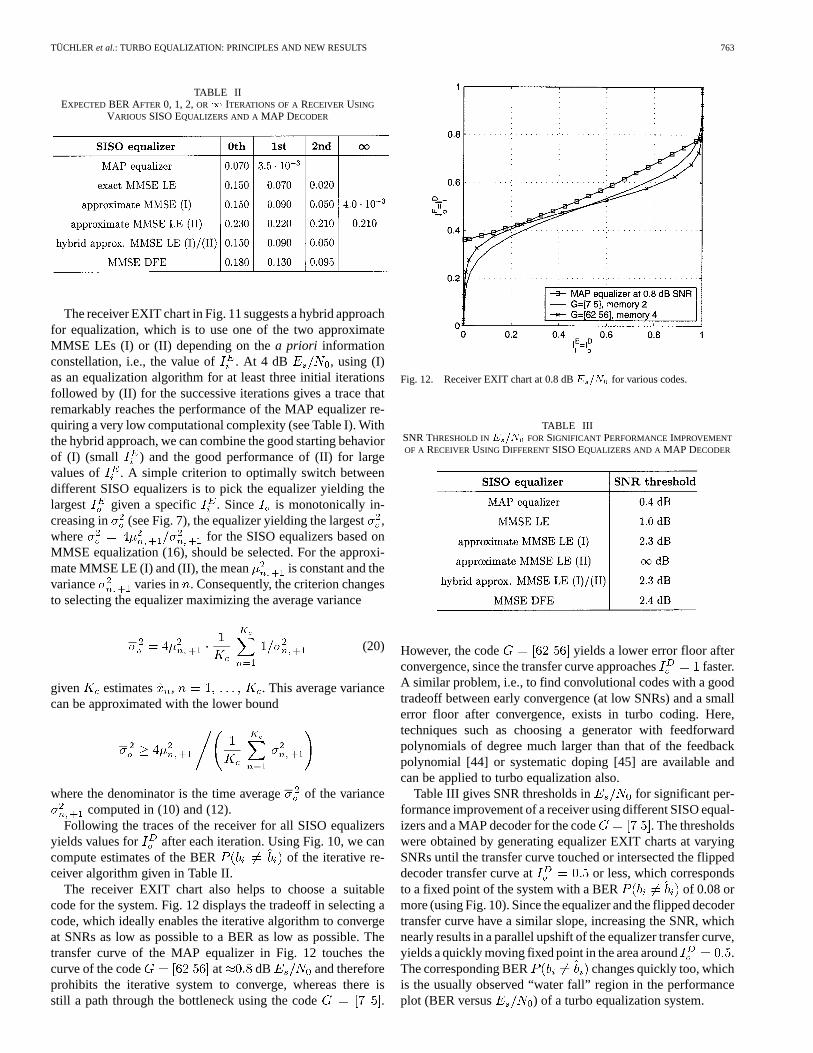
TABLE IIEXPECTEDBER AFTER 0, 1, 2,OR1 ITERATIONS OF ARECEIVER USING
VARIOUS SISO EQUALIZERS AND A MAP DECODER
The receiver EXIT chart in Fig. 11 suggests a hybrid approachfor equalization, which is to use one of the two approximateMMSE LEs (I) or (II) depending on thea priori informationconstellation, i.e., the value of . At 4 dB , using (I)as an equalization algorithm for at least three initial iterationsfollowed by (II) for the successive iterations gives a trace thatremarkably reaches the performance of the MAP equalizer re-quiring a very low computational complexity (see Table I). Withthe hybrid approach, we can combine the good starting behaviorof (I) (small ) and the good performance of (II) for largevalues of . A simple criterion to optimally switch betweendifferent SISO equalizers is to pick the equalizer yielding thelargest given a specific . Since is monotonically in-creasing in (see Fig. 7), the equalizer yielding the largest,where for the SISO equalizers based onMMSE equalization (16), should be selected. For the approxi-mate MMSE LE (I) and (II), the mean is constant and thevariance varies in . Consequently, the criterion changesto selecting the equalizer maximizing the average variance
(20)
given estimates , . This average variancecan be approximated with the lower bound
where the denominator is the time averageof the variancecomputed in (10) and (12).
Following the traces of the receiver for all SISO equalizersyields values for after each iteration. Using Fig. 10, we cancompute estimates of the BER of the iterative re-ceiver algorithm given in Table II.
The receiver EXIT chart also helps to choose a suitablecode for the system. Fig. 12 displays the tradeoff in selecting acode, which ideally enables the iterative algorithm to convergeat SNRs as low as possible to a BER as low as possible. Thetransfer curve of the MAP equalizer in Fig. 12 touches thecurve of the code at dB and thereforeprohibits the iterative system to converge, whereas there isstill a path through the bottleneck using the code .
Fig. 12. Receiver EXIT chart at 0.8 dBE =N for various codes.
TABLE IIISNR THRESHOLD INE =N FOR SIGNIFICANT PERFORMANCEIMPROVEMENT
OF A RECEIVERUSING DIFFERENTSISO EQUALIZERS AND A MAP DECODER
However, the code yields a lower error floor afterconvergence, since the transfer curve approaches faster.A similar problem, i.e., to find convolutional codes with a goodtradeoff between early convergence (at low SNRs) and a smallerror floor after convergence, exists in turbo coding. Here,techniques such as choosing a generator with feedforwardpolynomials of degree much larger than that of the feedbackpolynomial [44] or systematic doping [45] are available andcan be applied to turbo equalization also.
Table III gives SNR thresholds in for significant per-formance improvement of a receiver using different SISO equal-izers and a MAP decoder for the code . The thresholdswere obtained by generating equalizer EXIT charts at varyingSNRs until the transfer curve touched or intersected the flippeddecoder transfer curve at or less, which correspondsto a fixed point of the system with a BER of 0.08 ormore (using Fig. 10). Since the equalizer and the flipped decodertransfer curve have a similar slope, increasing the SNR, whichnearly results in a parallel upshift of the equalizer transfer curve,yields a quickly moving fixed point in the area around .The corresponding BER changes quickly too, whichis the usually observed “water fall” region in the performanceplot (BER versus ) of a turbo equalization system.
764 IEEE TRANSACTIONS ON COMMUNICATIONS, VOL. 50, NO. 5, MAY 2002
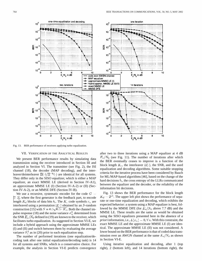
Fig. 13. BER performance of receivers applying turbo equalization.
VII. V ERIFICATION OF THEANALYTICAL RESULTS
We present BER performance results by simulating datatransmission using the receiver introduced in Section III andanalyzed in Section VI. The transmitter (see Fig. 2), the ISIchannel (18), the decoder (MAP decoding), and the inter-leaver/deinterleaver are identical for all systems.They differ only in the SISO equalizer, which is either a MAPequalizer, an exact MMSE LE (derived in Section IV-A1),an approximate MMSE LE (I) (Section IV-A-2) or (II) (Sec-tion IV-A-2), or an MMSE DFE (Section IV-B).
We use a recursive, systematic encoder for the code, where the first generator is the feedback part, to encode
length blocks of data bits . The code symbols areinterleaved using a permutation obtained by an -randomconstruction [15] with . Both the channel im-pulse response (18) and the noise variancedetermined fromthe SNR defined in (19) are known to the receiver, whichfacilitates turbo equalization. As suggested in Section VI-E, weinclude a hybrid approach using the approximate MMSE LEs(I) and (II) and switch between them by evaluating the averagevariance as in (20) prior to each equalization step.
The number of performed iterations (one equalization/de-coding task after one initial equalization/decoding task) is 14for all systems and SNRs, which is a conservative choice. Forexample, the analysis in Section VI-E predicts convergence
after two to three iterations using a MAP equalizer at 4 dB(see Fig. 11). The number of iterations after which
the BER eventually ceases to improve is a function of theblock length , the interleaver , the SNR, and the usedequalization and decoding algorithms. Some suitable stoppingcriteria for the iterative process have been considered by Bauchfor ML/MAP-based algorithms [46], based on the change of thehard decisions , the cross entropy of the LLRs communicatedbetween the equalizer and the decoder, or the reliability of theinformation bit decisions.
Fig. 13 shows the BER performance for the block length. The upper left plot shows the performance of sepa-
rate or one-time equalization and decoding, which exhibits theexpected behavior: a system using a MAP equalizer is best, fol-lowed by the MMSE DFE (for above 7.7 dB) and theMMSE LE. These results are the same as would be obtainedusing the SISO equalizers presented here in the absence ofapriori information, i.e., , . With this constraint, theexact MMSE LE and the approximate MMSE LE (I) are iden-tical. The approximate MMSE LE (II) was not considered. Alower bound on the BER performance is that of coded data trans-mission over an AWGN channel at the same as shownin Section VI-E.
Using iterative equalization and decoding, after 1 (topright), 2 (bottom left), and 14 iterations (bottom right), the

TÜCHLER et al.: TURBO EQUALIZATION: PRINCIPLES AND NEW RESULTS 765
TABLE IVBER AFTER 0, 1, 2,OR 14 ITERATIONS OF ARECEIVER USING DIFFERENTSISO EQUALIZERS AND A MAP DECODER
Fig. 14. Receiver EXIT charts with traces of iterative algorithms.
performance order changes drastically. A system using a MAPequalizer is still best, followed by the exact MMSE LE and thehybrid approximate MMSE LE (I)/(II). The receiver using theMMSE DFE provides only a minor performance improvement.The approximate MMSE LE (II) alone was not considered dueto its poor starting behavior. Using the approximate MMSE LE(I) alone provides good performance, however, with the hybridapproach, which does not alter the computational complexity,the performance is rather remarkable, approaching the AWGNbound.
Since the receiver performed only 14 iterations and the blocklength is finite, the SNR thresholds from Table III are some-what too optimistic. However, for the MAP equalizer, the exactMMSE LE, the approximate MMSE LE (I), and the hybrid ap-proach the derived SNR thresholds and match exactly (within0.1 dB) the actual threshold for which holds afterperforming all 14 iterations. The analysis fails for the MMSEDFE.
The BERs over successive iterations for each receiver algo-rithm at 4 dB are shown in Table IV and indicate the de-gree to which the BER analysis matches the actual performance.The predicted BER values in Table II closely match the simu-lated results for all SISO equalizers except for the MMSE DFE.This discrepancy becomes most obvious by looking at receiver
Fig. 15. Receiver EXIT charts with traces of a receiver using hybrid linearMMSE equalization.
EXIT charts at 4 dB SNR including the trace of the iterationprocess. The traces were obtained by computingor from10 equalizer/decoder output LLRs or , respec-tively, over several blocks as inSection IV-B. Figs. 14 and 15 de-pict receiver EXIT charts together with the simulated traces ofthe corresponding iterative algorithm at 4 dB . The traceof the system using an MMSE DFE does not follow the transfercurves of equalizer and decoder alone. Therefore, the EXITchart analysis cannot be applied to this algorithm. Moreover,the performance is worse than that of the linear counterpart, theexact MMSE LE, at the same computational complexity, a re-sult which was obtained for a number of different channels. Theonly difference between the equations used to obtain the outputLLRs with the exact MMSE LE (8) or the MMSE DFE(14) is to replace the means , , with the pastdecided estimates while computing and (whenand are set appropriately for the MMSE LE). While this stepoften provides performance gains forseparateequalization anddecoding, the early use of hard decisions appears to be detri-mental in an iterative algorithm.
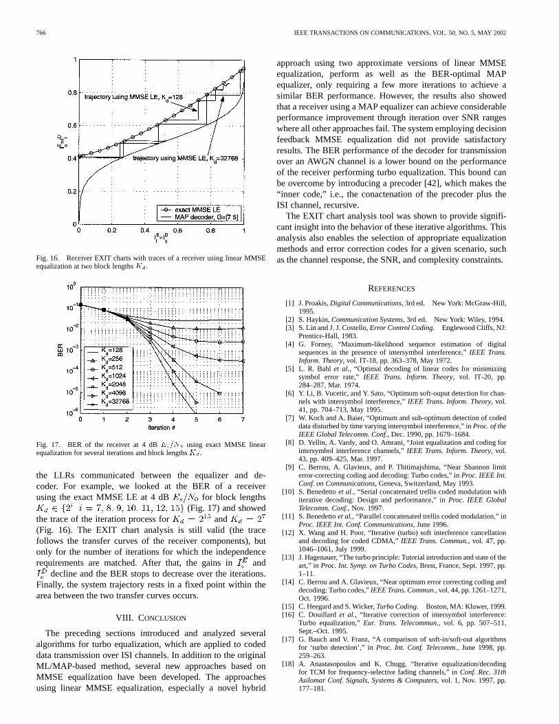
Figs. 16 and 17 depict the performance of the receiverfor varying block lengths . For short , repeated inter-leaving causes short cycles leading to dependencies within
766 IEEE TRANSACTIONS ON COMMUNICATIONS, VOL. 50, NO. 5, MAY 2002
Fig. 16. Receiver EXIT charts with traces of a receiver using linear MMSEequalization at two block lengthsK .
Fig. 17. BER of the receiver at 4 dBE =N using exact MMSE linearequalization for several iterations and block lengthsK .
the LLRs communicated between the equalizer and de-coder. For example, we looked at the BER of a receiverusing the exact MMSE LE at 4 dB for block lengths
(Fig. 17) and showedthe trace of the iteration process for and(Fig. 16). The EXIT chart analysis is still valid (the tracefollows the transfer curves of the receiver components), butonly for the number of iterations for which the independencerequirements are matched. After that, the gains in and
decline and the BER stops to decrease over the iterations.Finally, the system trajectory rests in a fixed point within thearea between the two transfer curves occurs.
VIII. C ONCLUSION
The preceding sections introduced and analyzed severalalgorithms for turbo equalization, which are applied to codeddata transmission over ISI channels. In addition to the originalML/MAP-based method, several new approaches based onMMSE equalization have been developed. The approachesusing linear MMSE equalization, especially a novel hybrid
approach using two approximate versions of linear MMSEequalization, perform as well as the BER-optimal MAPequalizer, only requiring a few more iterations to achieve asimilar BER performance. However, the results also showedthat a receiver using a MAP equalizer can achieve considerableperformance improvement through iteration over SNR rangeswhere all other approaches fail. The system employing decisionfeedback MMSE equalization did not provide satisfactoryresults. The BER performance of the decoder for transmissionover an AWGN channel is a lower bound on the performanceof the receiver performing turbo equalization. This bound canbe overcome by introducing a precoder [42], which makes the“inner code,” i.e., the conactenation of the precoder plus theISI channel, recursive.
The EXIT chart analysis tool was shown to provide signifi-cant insight into the behavior of these iterative algorithms. Thisanalysis also enables the selection of appropriate equalizationmethods and error correction codes for a given scenario, suchas the channel response, the SNR, and complexity constraints.
REFERENCES
[1] J. Proakis,Digital Communications, 3rd ed. New York: McGraw-Hill,1995.
[2] S. Haykin,Communication Systems, 3rd ed. New York: Wiley, 1994.[3] S. Lin and J. J. Costello,Error Control Coding. Englewood Cliffs, NJ:
Prentice-Hall, 1983.[4] G. Forney, “Maximum-likelihood sequence estimation of digital
sequences in the presence of intersymbol interference,”IEEE Trans.Inform. Theory, vol. IT-18, pp. 363–378, May 1972.
[5] L. R. Bahl et al., “Optimal decoding of linear codes for minimizingsymbol error rate,”IEEE Trans. Inform. Theory, vol. IT-20, pp.284–287, Mar. 1974.
[6] Y. Li, B. Vucetic, and Y. Sato, “Optimum soft-ouput detection for chan-nels with intersymbol interference,”IEEE Trans. Inform. Theory, vol.41, pp. 704–713, May 1995.
[7] W. Koch and A. Baier, “Optimum and sub-optimum detection of codeddata disturbed by time varying intersymbol interference,” inProc. of theIEEE Global Telecomm. Conf., Dec. 1990, pp. 1679–1684.
[8] D. Yellin, A. Vardy, and O. Amrani, “Joint equalization and coding forintersymbol interference channels,”IEEE Trans. Inform. Theory, vol.43, pp. 409–425, Mar. 1997.
[9] C. Berrou, A. Glavieux, and P. Thitimajshima, “Near Shannon limiterror-correcting coding and decoding: Turbo codes,” inProc. IEEE Int.Conf. on Communications, Geneva, Switzerland, May 1993.
[10] S. Benedettoet al., “Serial concatenated trellis coded modulation withiterative decoding: Design and performance,” inProc. IEEE GlobalTelecomm. Conf., Nov. 1997.
[11] S. Benedettoet al., “Parallel concatenated trellis coded modulation,” inProc. IEEE Int. Conf. Communications, June 1996.
[12] X. Wang and H. Poor, “Iterative (turbo) soft interference cancellationand decoding for coded CDMA,”IEEE Trans. Commun., vol. 47, pp.1046–1061, July 1999.
[13] J. Hagenauer, “The turbo principle: Tutorial introduction and state of theart,” in Proc. Int. Symp. on Turbo Codes, Brest, France, Sept. 1997, pp.1–11.
[14] C. Berrou and A. Glavieux, “Near optimum error correcting coding anddecoding: Turbo codes,”IEEE Trans. Commun., vol. 44, pp. 1261–1271,Oct. 1996.
[15] C. Heegard and S. Wicker,Turbo Coding. Boston, MA: Kluwer, 1999.[16] C. Douillard et al., “Iterative correction of intersymbol interference:
Turbo equalization,”Eur. Trans. Telecommun., vol. 6, pp. 507–511,Sept.–Oct. 1995.
[17] G. Bauch and V. Franz, “A comparison of soft-in/soft-out algorithmsfor ‘turbo detection’,” inProc. Int. Conf. Telecomm., June 1998, pp.259–263.
[18] A. Anastasopoulos and K. Chugg, “Iterative equalization/decodingfor TCM for frequency-selective fading channels,” inConf. Rec. 31thAsilomar Conf. Signals, Systems & Computers, vol. 1, Nov. 1997, pp.177–181.
TÜCHLER et al.: TURBO EQUALIZATION: PRINCIPLES AND NEW RESULTS 767
[19] J. Hagenauer and P. Hoeher, “A Viterbi algorithm with soft-decision out-puts and its applications,” inProc. IEEE Global Telecomm. Conf., 1989,pp. 1680–1686.
[20] D. Raphaeli and Y. Zarai, “Combined turbo equalization and turbo de-coding,” inProc. IEEE Global Telecomm. Conf., vol. 2, Nov. 1997, pp.639–643.
[21] M. Toegel, W. Pusch, and H. Weinrichter, “Combined serially concate-nated codes and turbo-equalization,” inProc. 2nd Int. Symp. on TurboCodes, Brest, France, Sept. 2000, pp. 375–378.
[22] S. Ariyavisitakul and Y. Li, “Joint coding and decision feedbackequalization for broadband wireless channels,”IEEE J. Select. AreasCommun., vol. 16, pp. 1670–1678, Dec. 1998.
[23] A. Glavieux, C. Laot, and J. Labat, “Turbo equalization over a frequencyselective channel,” inProc. Int. Symp. Turbo Codes, Brest, France, Sept.1997, pp. 96–102.
[24] D. Raphaeli and A. Saguy, “Linear equalizers for Turbo equalization: Anew optimization criterion for determining the equalizer taps,” inProc.2nd Int. Symp. Turbo codes, Brest, France, Sept. 2000, pp. 371–374.
[25] Z. Wu and J. Cioffi, “Turbo decision aided equalization for magneticrecording channels,” inProc. Global Telecomm. Conf., Dec. 1999, pp.733–738.
[26] A. Berthet, R. Visoz, and P. Tortelier, “Sub-optimal Turbo-detection forcoded 8-PSK signals over ISI channels with application to EDGE ad-vanced mobile system,” inProc. 11th Int. Symp. Personal, Indoor, andMobile Radio Communications, vol. 1, Sept. 2000, pp. 151–157.
[27] M. Tüchler, A. Singer, and R. Koetter, “Minimum mean squareerror equalization usinga priori information,” IEEE Trans. SignalProcessing, vol. 50, pp. 673–683, Mar. 2002.
[28] H. Poor, An Introduction to Signal Detection and Estimation, 2nded. New York: Springer-Verlag, 1994, pp. 221–229.
[29] M. Tüchler, “Iterative equalization using priors,” Master’s thesis, Uni-versity of Illinois, Urbana-Champaign, IL, 2000.
[30] M. Tüchler and J. Hagenauer, “Turbo equalization using frequency do-main equalizers,” inProc. Allerton Conf., Monticello, IL, Oct. 2000, pp.1234–1243.
[31] S. Benedetto, D. Divsalar, G. Montorsi, and F. Pollard, “Serial con-catenation of interleaved codes: Performance analysis design, and itera-tive decoding,”IEEE Trans. Inform. Theory, vol. 44, pp. 909–926, May1998.
[32] S. Benedetto and G. Mondorsi, “Unveiling Turbo codes: Some resultson parallel concatenated coding schemes,”IEEE Trans. Inform. Theory,vol. 42, pp. 409–428, Mar. 1996.
[33] T. Richardson, “The geometry of Turbo decoding dynamics,”IEEETrans. Inform. Theory, vol. 46, pp. 9–23, Jan. 2000.
[34] D. Agrawal and A. Vardy, “The Turbo decoding algorithm and its phasetrajectories,”IEEE Trans. Inform. Theory, vol. 47, pp. 699–722, Feb.2001.
[35] S. ten Brink, “Convergence of iterative decoding,”Electron. Lett., vol.35, pp. 806–808, May 1999.
[36] , “Convergence behavior of iteratively decoded parallel concate-nated codes,”IEEE Trans. Commun., vol. 40, pp. 1727–1737, Oct. 2001.
[37] T. Richardson and R. Urbanke, “The capacity of low density parity-check codes under message passing decoding,”IEEE Trans. Inform.Theory, vol. 47, pp. 599–618, Feb. 2001.
[38] K. Narayanan, “Effect of precoding on the convergence of Turbo equal-ization for partial response channels,”IEEE J. Select. Areas Commun.,vol. 19, pp. 686–698, Apr. 2001.
[39] H. Gamal and A. Hammons, Jr., “Analyzing the Turbo decoder usingthe Gaussian approximation,”IEEE Trans. Inform. Theory, vol. 47, pp.671–686, Feb. 2001.
[40] S. Chung, T. Richardson, and R. Urbanke, “Analysis of sum-productdecoding of low-density-parity-check codes using a Gaussian approxi-mation,” IEEE Trans. Inform. Theory, vol. 47, pp. 657–670, Feb. 2001.
[41] D. Divsalar, S. Dolinar, and F. Pollara, “Serial Turbo trellis coded mod-ulation with rate-1 inner code,” inProc. Int. Symp. Information Theory,2000, p. 194.
[42] I. Lee, “The effect of a precoder on serially concatenated coding systemswith an ISI channel,”IEEE Trans. Commun., vol. 49, pp. 1168–1175,July 2001.
[43] R. Ramamruthy and W. Ryan, “Convolutional double accumulate codes(or double Turbo DPSK),”IEEE Commun. Lett., vol. 5, pp. 157–159,Apr. 2001.
[44] P. Massey, O. Takeshita, and D. Costello, “Contradicting a myth: GoodTurbo codes with large memory order,” inProc. Int. Symp. InformationTheory, 2000, p. 122.
[45] S. ten Brink, “Iterative decoding trajectories of parallel concatenatedcodes,” inProc. 3rd IEEE/ITG Conf. Source and Channel Coding, Mu-nich, Germany, Jan. 2000, pp. 75–80.
[46] G. Bauch, H. Khorram, and J. Hagenauer, “Iterative equalization and de-coding in mobile communications systems,” inProc. 2nd Eur. PersonalMobile Comm. Conf., Sept./Oct. 1997, pp. 307–312.
Michael Tüchler was born on October 6, 1975, inHildburghausen, Germany. He studied electrical en-gineering from 1995 to 1997 at the Technical Univer-sity Ilmenau, Germany, and from 1997 to 1998 at theTechnical University Munich, Germany. He receivedthe M.S. degree from the University of Illinois at Ur-bana-Champaign, in 2000. He is currently workingtoward the Ph.D. degree at the Institute for Communi-cations Engineering at the Technical University Mu-nich.
In 2001, he was a Visiting Scientist at the IBMZurich Research Laboratory, Switzerland. His research interests include codingtheory and equalization with application to wireless and data storage communi-cation systems.
Ralf Koetter was born on October 10, 1963, inKönigstein, Germany. He received the Diploma inelectrical engineering from the Technical UniversityDarmstadt, Germany in 1990 and the Ph.D. degreefrom the Department of Electrical Engineering atLinköping University, Sweden.
From 1996 to 1997, he was a Visiting Scientistat the IBM Almaden Research Laboratory, SanJose, CA. He was a Visiting Assistant Professorat the University of Illinois at Urbana/Champaignand Visiting Scientist at CNRS in Sophia Antipolis,
France, during the years 1997 to 1998. He joined the faculty of the Universityof Illinois at Urbana/Champaign in 1999 and is currently an Assistant Professorat the Coordinated Science Laboratory at the University. His research interestsinclude coding and information theory and their application to communicationsystems.
Dr. Koetter served as Associate Editor for Coding Theory and Techniquesfrom 1999 to 2001 for the IEEE TRANSACTIONS ON COMMUNICATIONS. In2000, he started a term as Associate Editor for Coding Theory of the IEEETRANSACTIONS ON INFORMATION THEORY. He received an IBM InventionAchievement Award in 1997 and an NSF CAREER Award in 2000, and anIBM Partnership Award in 2001.
Andrew C. Singer was born in Akron, OH, in 1967.He received the S.B., S.M., and Ph.D. degrees, all inelectrical engineering and computer science, from theMassachusetts Institute of Technology, Cambridge,in 1990, 1992, and 1996, respectively.
Since 1998, he has been on the faculty of theDepartment of Electrical and Computer Engineeringat the University of Illinois at Urbana-Champaign,where he is currently an Assistant Professor inthe Electrical and Computer Engineering Depart-ment, and a Research Assistant Professor in the
Coordinated Science Laboratory. During the academic year 1996, he was aPost-Doctoral Research Affiliate in the Research Laboratory of Electronicsat MIT. From 1996 to 1998, he was a Research Scientist at Sanders, ALockheed Martin Company, Manchester, NH. His research interests includestatistical signal processing and communication, universal prediction and datacompression, and machine learning.
Prof. Singer was a Hughes Aircraft Masters Fellow and was the recipientof the Harold L. Hazen Memorial Award for excellence in teaching in 1991.In 2000, he received the National Science Foundation CAREER Award and in2001 he received the Xerox Faculty Research Award. He is currently a memberof the MIT Educational Council, Eta Kappa Nu, and Tau Beta Pi.

![Multilevel-Coded QAM With MIMO Turbo-Equalization in ... · systems have to be more optimized toward packet-based transmission. The original suboptimal algorithms [2]–[4] for turbo-equalization](https://img.dokumen.tips/doc/110x75/5ecace6f261e3667c0215f45/multilevel-coded-qam-with-mimo-turbo-equalization-in-systems-have-to-be-more.jpg)


![Turbo equalization: principles and new results ...singer/pub_files/Turbo...Combined turbo codingand equalization [20],[21]includes threeor morelayers: two or more coding layers as](https://img.dokumen.tips/doc/110x75/600724985f3e7f70086519b2/turbo-equalization-principles-and-new-results-singerpubfilesturbo-combined.jpg)


![LMMSE turbo equalization based on factor graphsliping/Research/Journal/53... · factor graphs, Gaussian message passing, linear MMSE. I. INTRODUCTION T URBO equalization [1]-[8] is](https://img.dokumen.tips/doc/110x75/6007243dfe2d385f6d5d46ad/lmmse-turbo-equalization-based-on-factor-lipingresearchjournal53-factor.jpg)