Embed Size (px)
Citation preview

TUBULARSKYLIGHT
(800) 388-0293
ImportantBe sure to first read and then follow all step-by-step instructions completely. This will help to insure proper installation and functionality. Expect installation to take from 1 to 3 hours.
Installation Instructions

2 3
For cathedral ceiling, see Section 10.
For long tube shaft installation, see Section 11.
For 14” skylight with 16” on-center rafter spacing see Section 5.
REVIEW THIS INFORMATION PRIOR TO BEGINNING INSTALLATION
CautionThe Skytube is not designed to hold your weight or the weight of tools or other objects.Walking/placing objects on the SkyTube could cause personal injury and property damage. A damaged SkyTube should be repaired immediately.
For safe installation and use, do not deviate from these installation instructions.
Warning:Working on a roof is potentially dangerous butyou can significantly reduce the risk by followingthese precautions:• Never work in wet, windy or cold conditions.Roofing materials can be slippery when wet;asphalt shingles are brittle when cold and maycrumble underfoot. Plan your installation fora calm, dry day.• Wear shoes with slip-resistant soles.
Safety information:• Wear safety glasses and work gloves whenusing power tools.• Use protective work gloves while handling tubesections to protect hands from sharp edges.
Pre-Installation Items to Review:Tube Installation/Location• Your Skytube kit comes with enoughtubing for a 30" installation (50" for a Pro 3 Kit) – if you require more tubing, you can purchase additional extension tubes through your retailer.• For best results always attempt to install the tubeas straight as possible (this would locate thedome/flashing directly above the ceiling diffuser).• Make sure that the location you pick on your rooffor your dome/flashing is exposed to direct sunlightthroughout the day. You will not want any trees,chimneys, etc. to cast a shadow on your tube.• Before installation, carefully survey the attic areaof your desired location. Make sure your tube canavoid any wiring, plumbing, roof valleys, ceilingmounted registers/fans, etc.
Building Codes:• Consult your local building official about localconstruction ordinances before starting yourinstallation.• Consult your community covenants. Some subdivisions may not allow Skytube installed on the street side of home.Determining roof pitch:• “Roof Pitch” is how far the roof drops verticallyfor every 12” of horizontal run.• Spun metal flashings can be used on flat roof to 12:12 roof pitch.• Sloped composite flashings require a minimum pitch of 3:12 and a maximum of 12:12.
These instructions have been designed to help install your Wasco Skytube easily and safely. We’ve included a parts list, list of tools required, installation instructions for a variety of ceiling types, handy tips, and safety precautions. Please read these instructions thoroughly before installing your Wasco Skytube. Pay particular attention to the assembly diagrams, assembly order, and part names. Identify and organize all parts before assembly. Make a list of the tools and components you will need for each installation location. Following these instructions carefully will greatly enhance your ability to install your Skytube and enjoy flawless performance for many years.
Section iWhat You Need To Know
POTENTIAL FIRE HAZARD. After removing the film lining from the interior of tube shaft, a reflective inner surface is created. DO NOT leave tube shaft components unattended or
exposed to direct sunlight prior to full installation. Exposed surfaces may catch fire or incur heat
damage as a result of focused sunlight until the tube shaft is fully installed with diffuser in place.
WARNING

2 3
Limited Warranty for Wasco SkytubeEffective 12/11
Warranty Coverage
Subject to the conditions, exclusions and limitations herein, Wasco Products, Inc. (“Wasco”) warrants that its Skytube Product (“Product”) is free from defects in material and workmanship that would render the Product unfit for its normal and recommended use.
THIS LIMITED LIFETIME WARRANTY APPLIES AND EXTENDS ONLY TO THE ORIGINAL CONSUMER PURCHASING THIS PRODUCT. THE DURATION OF THIS WARRANTY BEGINS ON THE DATE OF PURCHASE BY THE CONSUMER.
Exclusions from Coverage
This warranty does not cover:• Defects or damages arising out of shipment by common carriers, private transportation or other means of transportation.• Defects or damages arising out of improper handling or cleaning, defective or improper installation (including installation not in accordance with Wasco’s installation instructions), accident, act of God, intentional human act, misuse or abuse, or any other circumstances beyond the control of Wasco.• Products installed in or submitted to high heat, high moisture, high vibration, or extreme temperature changes.• Products subjected to stress resulting from (i) localized application of heat, (ii) movement of building and /or building components, or (iii) expansion or contraction of framing members.• Replacement products beyond the balance of the remaining warranty period applicable to the original Product or accessory which is replaced. • Labor, shipping or other charges incurred or claimed by the Customer.• Accessories, flashing or other installation materials manufactured or sold by persons other than Wasco.
Warranty Claim Procedures
If within the applicable warranty period the Customer discovers a defect in the Product or an accessory which is covered by this warranty, the Customer must follow this procedure:
1. The Customer must promptly present a written claim to the Customer Service Manager, Wasco Products, Inc., 85 Spencer Drive, Unit A, Wells, ME 04090.
2. The Customer must use reasonable diligence to include in the written claim all of the following:
a. An adequate description of the claimed defect(s); b. Identification of Product (size, design, type and model number).; c. Date of the Customer’s purchase, place of purchase, and the date of delivery to the Customer.
3. The Consumer must, if requested by Wasco, permit Wasco or its representative to inspect the Product either in person or via appropriate photographs of said Product.
Remedies
After receiving a valid claim, Wasco will, at its option, provide a replacement Product (or part, as appropriate) of like kind and design.
If Wasco elects to provide a replacement Product, the limited warranty on the replacement will last only for the balance of the original Product warranty period. If the Customer fails to provide satisfactory proof of the date of purchase, the date of manufacture shall be used instead.
WASCO’S LIABILITY UNDER THIS WARRANTY IS LIMITED TO THE ABOVE, AND Wasco WILL IN NO EVENT BE RESPONSIBLE FOR SHIPPING, LABOR, REMOVAL OF ORIGINAL PRODUCT, INSTALLATION OF REPLACEMENT PRODUCT, FINISHING EXPENSES, OR OTHER CHARGES, COSTS OR CLAIMS INCURRED BY THE CONSUMER.
Disclaimer of Warranty
NO IMPLIED WARRANTY, INCLUDING WARRANTY OF MERCHANTABILITY OR OF FITNESS FOR A PARTICULAR PURPOSE, SHALL APPLY TO THE PRODUCT (OR ANY REPLACEMENT) BEYOND THE DURATION OF THIS WRITTEN WARRANTY. (Some states/provinces do not allow limitations on how long an implied warranty lasts, so the above limitation may not apply to you.)
Limitation of Remedies
THE REMEDIES SET FORTH ABOVE ARE THE CONSUMER’S EXCLUSIVE REMEDIES FOR BREACH OF WARRANTY OR NEGLIGENCE. IN NO CASE SHALL Wasco BE LIABLE TO THE CONSUMER OR ANY OTHER PERSON FOR ANY GENERAL, SPECIAL, INCIDENTAL OR CONSEQUENTIAL DAMAGES. (Some states/provinces do not allow the exclusion or limitation of incidental or consequential damages, so the above limitations or exclusions may not apply to you.)
Unless modified in a later writing signed by both Wasco and Consumer, this warranty is the complete and exclusive warranty related to the Product, and it supersedes all earlier agreements and other communications relating to the Product. No employee of Wasco or any other party is authorized to make any warranty in addition to this warranty. Invalidation of any one or more of the other provisions of this warranty shall not invalidate or affect one of the other provisions. This warranty is not transferable.
This warranty gives the Consumer specific legal rights, and the Consumer may also have other legal rights which may vary from state to state, or province to province.
Wasco Skylights • 85 Spencer Drive, Unit A • Wells, ME 04090 • www.wascoskylights.com
Section ii

4 5
(4) dome washers
(4) 3/4” dome screws
(9) 2” flashing screws
(9) flashing washers
(1) roll of foil tape
(2) hole cutting templates
Solar Lens® Dome(10” Dome shown)
Adjustable Tubes
Roof Flashing
Ceiling Ring with Flip Tabs
PARTS INCLUDED
Low-Profile InsulatedDiffuser Lens Assembly
Carpenter Pencil
Claw Hammer
Coat Hanger Wire
Flat Pry Bar
Ladder
Metal Shears
Phillips Screwdriver
Plumb Line
Power Drill
Power Saw
Safety Equipment
Measuring Tape
Roof Sealant(Not provided in kit)
Exterior Clear Pure Silicone(Not provided in kit)
Shim or Ruler
TOOLS NEEDED
Read through the section specific to your roof for additional parts and tools.
NOTE
Section iiiTools & Parts Identification

4 5
In the attic, locate the coat hanger wire. Adjust its location, centering the opening for the tube between the framing members. Check wire visibility in the ceiling below as well as from the hole that will be cut in the roof.
2
Using a stud finder or hammer, find a location between the ceiling joists. Push a screwdriver or nail through the desired position.
Cut and insert a section of coat hanger wire through the hole. This will make it easier to identify the hole location in the attic.
1
These instructions outline the step-by-step process to install an Wasco Skytube. Before starting, review all instructions and become familiar with the parts shown on the previous page.
SPECIAL NOTES• Always use safe procedures.• Wear safety glasses when working with tools. • Check all measurements before cutting or drilling. • It is helpful to have a second person assist during installation.
Refer to Pre-installation Checklist for tube location tips in section i.
NOTE
Section 1Determine The Desired PositionOf The Skytube In The Ceiling
1
2
Carpenter Pencil
Claw Hammer
Coat Hanger Wire
Measuring Tape
Phillips Screwdriver
TOOLS & PARTS

6 7
Angled Tube InstallationIn the attic, if there are obstructions at the roof location (valleys, wires, pipes, ducts, framing, etc.), adjust tubes up to a combined 45° angle to find a path that avoids interference. Center the opening for the tube between the framing members. Drive a nail up into the roof deck and through the shingles.
2
Straight Tube InstallationIn the attic, use a plumb line to find a straight location from the ceiling hole to the roof location. Center the opening for the tube between the framing members. Drive a nail up into the roof deck and through the shingles.
1
1
Carpenter Pencil
Claw Hammer
Ladder
Measuring Tape
Phillips Screwdriver
Plumb Line
Safety Equipment
TOOLS & PARTS
2
Straight Tube Installation Angled Tube Installation
Trial-fitting your tubing will help in determining adjustablilty and need for additional extensions.
NOTE
Section 2Locating The Roof Position

6 7
1
Adjustable Tubes
Hole Cutting Template
TOOLS & PARTS Remove protective film from inside all tubes.1
11
It is recommended that you put all of your tools and rooftop components in a box or bag for easy transferto the roof. See Section 4.
TIP
From the hardware pack, be sure to use the correct hole cutting template for the selected tube size.
CAUTION
10” Template
14” Template
Section 3Prepare The Components
POTENTIAL FIRE HAZARD. After removing the film lining from the interior of tube shaft, a reflective inner surface is created. DO NOT leave tube shaft components unattended or
exposed to direct sunlight prior to full installation. Exposed surfaces may catch fire or incur heat
damage as a result of focused sunlight until the tube shaft is fully installed with diffuser in place.
WARNING
8 9
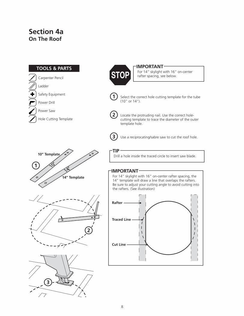
Select the correct hole cutting template for the tube (10” or 14”).
1
Locate the protruding nail. Use the correct hole-cutting template to trace the diameter of the outer template hole.
2
Use a reciprocating/sabre saw to cut the roof hole.3
Drill a hole inside the traced circle to insert saw blade.TIP
3
2
1
Carpenter Pencil
Ladder
Safety Equipment
Power Drill
Power Saw
Hole Cutting Template
TOOLS & PARTS
10” Template
14” Template
Rafter
Traced Line
Cut Line
For 14” skylight with 16” on-center rafter spacing, the 14” template will draw a line that overlaps the rafters.Be sure to adjust your cutting angle to avoid cutting into the rafters. (See illustration)
IMPORTANT
For 14” skylight with 16” on-center rafter spacing, see below.
IMPORTANT
Section 4aOn The Roof

8 9
The vertical seam of the reflective tube should point to the East or West to avoid irregular light patterns in your room.
TIP
Use a flat pry bar to carefully break the seals on the shingles' upslope above the cuthole. Use a claw hammer to remove nails on the shingles above the cut hole.
1
Secure flashing to roof with 2” Flashing Screws and Washers. Use 9 screws & washers in an evenly spaced, circular pattern around the 10” or 14” hole. The circular pattern should be a 21” diameter for the 10” unit and a 24” diameter pattern on the 14” unit.
4
Caulk Gun
Claw Hammer
Flat Pry Bar
Ladder
Phillips Screwdriver
2” Screws
3/4” Washers
Roofing Sealant (not provided in kit)
Safety Equipment
Roof Flashing
Top Adjustable Tube
TOOLS & PARTS
Generously apply roof sealant around bottom of flashing. Slide top and sides of roof flashing under top shingles.
2
Slide Top Adjustable Tube into the flashing to check for proper alignment.
3
For short shaft cathedral style installation see Section 10. Do not install dome yet.
IMPORTANT
2Sealant
Section 4bOn The Roof
4
3
1
1
2
2
4

10
Ladder
Phillips Screwdriver
Safety Equipment
3/4” Dome Screws
Dome Washers
Top Adjustable Tube
Solar Dome
Exterior Clear Pure Silicone(not provided in kit)
TOOLS & PARTS For angled tube installation, reach and adjust the Adjustable Tube so it points to the wire in the ceiling, or adjust the angle of the tube and then insert tube into flashing.
1
Cover dome screw heads and washers with an exterior clear pure silicone .
3
Using the 3/4”dome screws and dome washers (dome washers have the rubber backing – rubber backing should face the dome), mount the dome on the flashing aligning the “N” (molded into outer edge of the dome) towards the North.
2
Dome screws should be snug but do not over-tighten. Over-tightening can create too much pressure against the dome.
TIP
1
It is easier if 2 people work/turn the tube in opposite directions to angle the tube as needed.
NOTE
2
Align Toward North
Mount Dome
Section 4cOn The Roof

10 11
Pencil
Phillips Screwdriver
Power Saw
Hole Cutting Template
Ceiling Trim Ring
TOOLS & PARTS
Use a keyhole/drywall saw to cut the hole.2
Using the correct Hole Cutting Guide for your size tube and a pencil, locate protruding wire in the ceiling and trace the diameter of the ceiling inner hole using the template marked “A”.
1
Slide the Trim Ring up into your ceiling hole. Make sure the flip tabs are turned in. Reach through hole and turn flip tabs out to hold ring in place.
3
2
3
1
You may have to drill a hole inside the traced diametercircle to insert saw blade.
TIP
For 14” skylight with 16” on-center rafter spacing, see box below.
IMPORTANT
Secure the ceiling trim ring by tightening the screws.4
4
Rafter
Traced Line
For 14” skylight with 16” on-center rafter spacing, the 14” template will draw a line that overlaps the rafters.Be sure to adjust your cutting angle to avoid cutting into the rafters. (See illustration)
IMPORTANT
Cut Line
Flip TabTrim Ring
Section 5Inside The Room

12
Measuring Tape
Bottom Adjustable Tube
Foil Tape
TOOLS & PARTS
1
If you have an angled installation you will need to twist your Bottom Adjustable Tube so it lines up with the Top Adjustable Tube above. (Be sure you have removed the protective film.)
2
Measure distance from the top of Roof Flashing to ceiling (See illustration) to determine proper trimming of length of tubes. Refer to “Tube Length Chart” in Section 8 for cutting recommendations if you need to shorten the tubes.
3
Slide Bottom Adjustable Tube over the outside of Top Adjustable Tube.4
5
Tape ALL seams securely with Foil Tape to keep dust, moisture, and insects out of the tube.6
1
Distance from top of flashing to face of ceiling (take longest measurement)
3
6
At this point, if you purchased a dimmer or combo kit, this is where you reference the dimmer instructions packaged with the dimmer unit.
IMPORTANT
Gently set the Bottom Adjustable Tube flange down on the trim ring. Do not snap in place at this time.
Now you can push down to lock the Bottom Adjustable Tube securely into the lock tabs of the ceiling trim ring.
It is easier if 2 people work/turn the tube in opposite directions to angle the tube as needed.
NOTE
Section 6In The Attic
Flip Tab Lock Tab
The vertical seam of the reflective tube should point to the East or West to avoid irregular light patterns in your room.
TIP

13
1
Carpenter Pencil
Metal Shears
Safety Equipment
Safety Glasses
Extension Tubes
Gloves
TOOLS & PARTS
Be sure to measure and cut if necessary, before removing adhesive strip and assembling the Extension Tube. Wear gloves when working with sharp edges.
1
When trimming Extension Tubes, always measure and start from the wide end where tube end diameter = 10” or 14”.
TIP
1 After referring to “Tube Length Chart” in Section 8, use metal shears to shorten the Extension Tube. Allow for a 1” overlap at each end where you will connect each tube to another.
2
1 Once Extension Tubes are sized to the proper length, remove tan backing paper from adhesive strip on edge of Extension Tube. Beginning at one end of the Extension Tube, over-lap the edges of the tube/s, aligning the edge of the tube along the crimp on the other side.
3
Once contact is made with adhesive strip on an Extension Tube, parts cannot be repositioned.
IMPORTANT
Adhesive Strip
Trimmed Extension Tube
Section 7When Cutting Your Tube...

14
Section 8Tube Length Chart
More Than 29”16” Through 29”Less Than 15”
(Must use bottom adjustable tube only )
Tube Extension (Sold separately )

14 15
TOOLS & PARTS
Installation Complete!
Install the Diffuser Assembly by aligning the Diffuser with the three tabs on the Trim Ring. Turn clockwise until snug in place on the ceiling.
1
Diffuser should be rotated at least through two“clicks”. (Full rotation is four “clicks”) to attachto Trim Ring.
TIP
Ceiling Trim Ring
1
Ring & Lens Diffuser
Diffuser Lens Assembly
Section 9Inside The Room

16
Ladder
Pencil/Marker
Safety Equipment
Shim or Ruler
Bottom Adjustable Tube
TOOLS & PARTS
Place bottom adjustable tube (with the flanged end down) through the rough-cut hole in the ceiling.
1
Guide the top portion of the tube up through the roof flashing so it protrudes upward through the flashing collar on the roof.
2
Place a temporary shim or ruler across the ceiling opening.(Approx 1/8” thick)
3
Center the tube over the ceiling cut-out, resting the tube down onto the shim. (The shim will keep the tube from falling through the ceiling.)
4
Start with regular installation instructions beginning in Section 1.
On the roof, mark the protruding tube at the top of the flashing collar with a felt pen. This will indicate where the extra length of tubing must be trimmed off for a short shaft install.
5
1
3
5
2
4
The solar powered dimmer will not work with a cathedral ceiling or some short installations due to space restrictions.
NOTE
Section 10aCathedral Ceiling/Short Shaft Installation

17
Gloves
ladder
Metal Shears
Safety Equipment
Bottom Adjustable Tube
Ceiling Ring
TOOLS & PARTS At the ceiling, slide the temporary shim out of your way and pull tube section back out of the ceiling
6
Wearing protective gloves, carefully trim away the excess aluminum tubing, using your felt pen marks as a guide.
7
Remove the protective film from the inside of the tubing.
8
Place the tube section back into the ceiling making sure to align and center it inside the roof flashing collar. Place shim back across the cut-out.
9
Open the diffuser assembly box and separate the ceiling ring from the diffuser. Install only the Ceiling Ring into the cut-out.
10
You can now remove the shim from the ceiling and allow the tube to rest centered over the ceiling ring.
11
18
6
67
9
10
11
Section 10bCathedral Ceiling/Short Shaft Installation

18
Ladder
Phillips Screwdriver
Safety Equipment
3/4 Dome Screws
Dome Washers
Bottom Adjustable Tube
Diffuser
Solar Lens Dome
TOOLS & PARTS
Installation Complete!
While wearing gloves, carefully press downward on the trimmed end of the tube. It will lock down into the 3 plastic locking tabs located in the Ceiling Trim Ring, securing the tube into the rubber gasket in the ceiling trim ring.
12
Install the Solar Lens Dome onto the flashing collar. See dome install instructions Section 4c, then return to this page for further instructions.
13
Rotate the Insulated Ceiling Diffuser onto the Ceiling Trim Ring. See Section 9.
14
13
14
12
Section 10cCathedral Ceiling/Short Shaft Installation – On The Roof
Use protective work gloves — The trimmed edge of the tube will be sharp!
IMPORTANT

19
On roof, locate and install Top Adjustable Tube into roof flashing. Install Ceiling Ring at ceiling. Install Bottom Adjustable Tube in attic as seen in diagram.
1
Frame 2 x 4 support between joists. Span from roof to ceiling with a length of 2 x 4 flat to outside of each Adjustable Tube, creating a “spine”.
2
Put a (2) 2-1/2” pan-head, sheet metal screw (not included) in each connecting extension.
3
Slide next tube section in and attach with screw/s. Continue until all but one extension is connected. Cut and install last section of extension tube.
4
Tape ALL joints. Go to Section 9 to continue standard install.5
Long Shaft InstallationFor long shaft installation, use steps listed below, referring to those listed on previous pages for more specific install details.
Section 11Long Shaft Installation
(2) 2-1/2” Pan Head Sheet Metal Screws (Not Included)
3/32” Bit
Drill
Phillips Drill Bit
Measuring Tape
TOOLS & PARTS
Extension Tube(s)
Top AdjustableTube
BottomAdjustable Tube
2 x 4 Support
(2) 2-1/2” Sheet MetalScrews
3
2
1
5
5
1
20 21
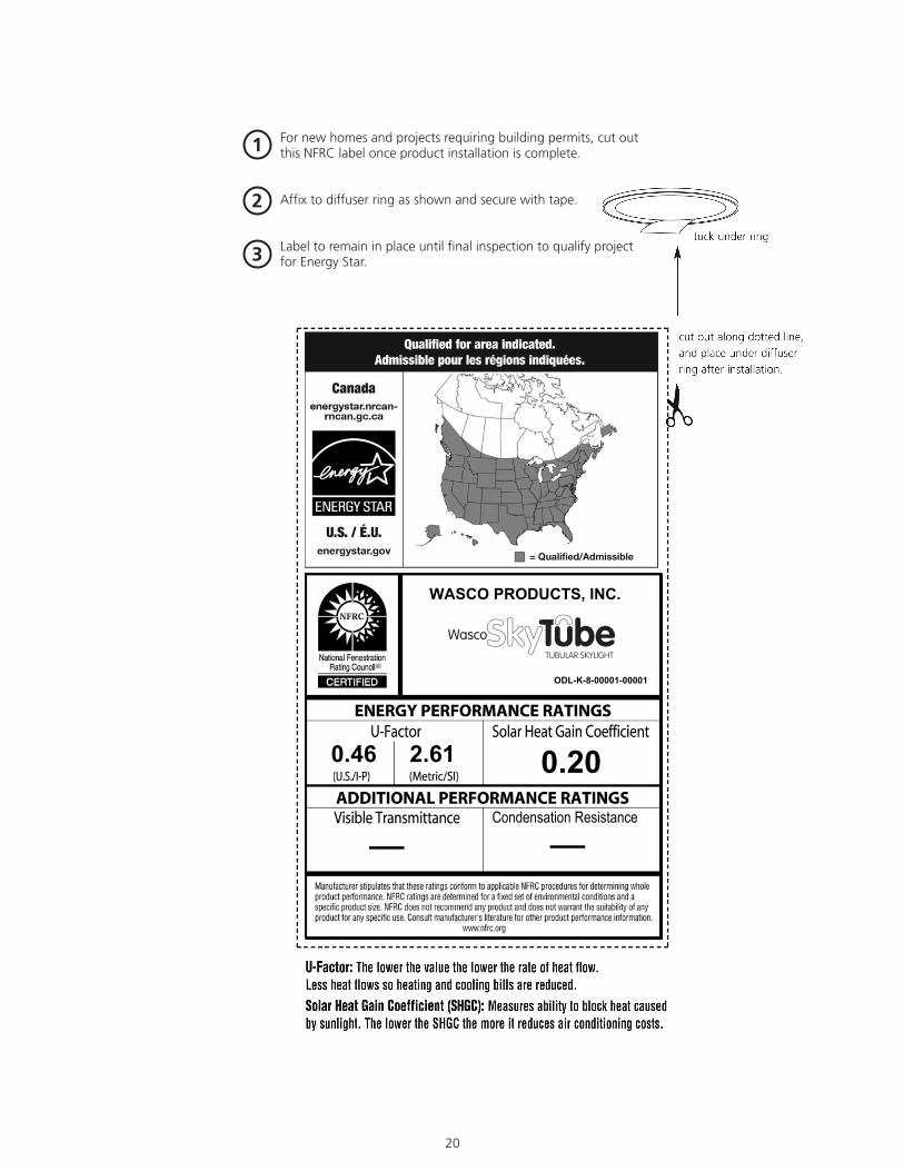
WASCO PRODUCTS, INC.SkyTube Tubular Skylight
ODL-K-8-00001-00001
0.46 2.61 0.20
__ Condensation Resistance__
1
2
3
For new homes and projects requiring building permits, cut out this NFRC label once product installation is complete.
Affix to diffuser ring as shown and secure with tape.
Label to remain in place until final inspection to qualify project for Energy Star.

20 21
Attn: Customer Service
WASCO PRODUCTS, INC.85 SPENCER DRIVE, UNIT AWELLS, ME 04090
If you would like additional
information on Wasco products, visit
our website at www.wascoskylights.com or
call our toll free number: 1-800-388-0293.
Wasco Products, Inc.85 Spencer Drive, Unit A Wells, ME 04090www.wascoskylights.com
Thank you for your purchase of this Wasco product.
FOLD HERE
TAPE HERE • DO NOT STAPLE
FIRST-CLASSPOSTAGEREQUIRED
22
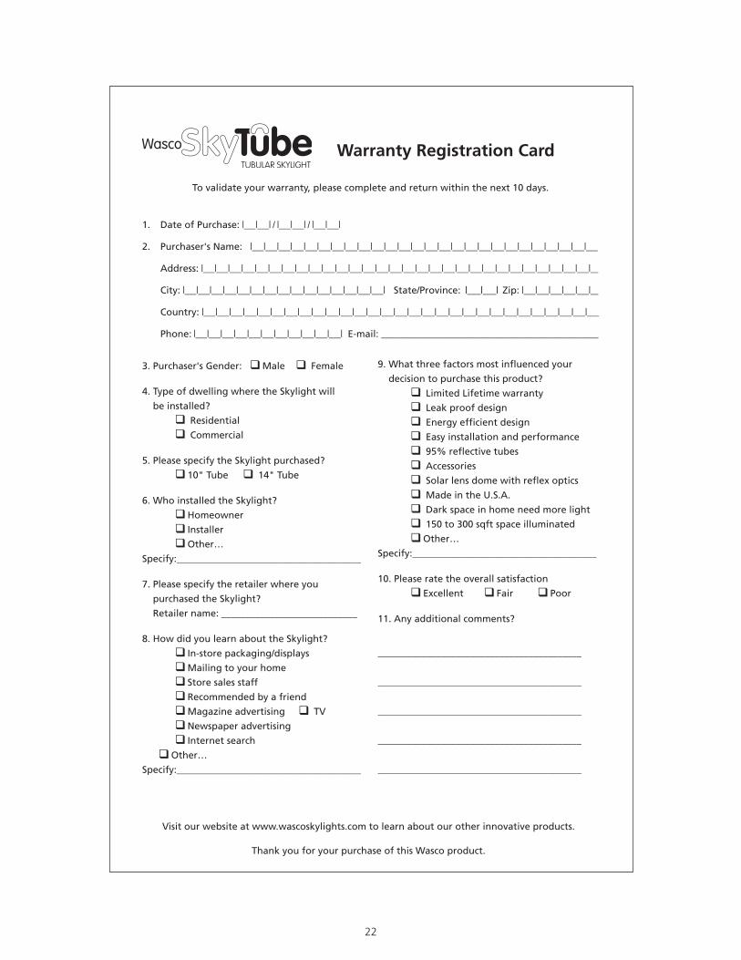
1. Date of Purchase: |___|___| / |___|___| / |___|___|
2. Purchaser's Name: |___|___|___|___|___|___|___|___|___|___|___|___|___|___|___|___|___|___|___|___|___|___|___|___|___|___
Address: |___|___|___|___|___|___|___|___|___|___|___|___|___|___|___|___|___|___|___|___|___|___|___|___|___|___|___|___|___|__
City: |___|___|___|___|___|___|___|___|___|___|___|___|___|___|___| State/Province: |___|___| Zip: |___|___|___|___|___|__
Country: |___|___|___|___|___|___|___|___|___|___|___|___|___|___|___|___|___|___|___|___|___|___|___|___|___|___|___|___|___
Phone: |___|___|___|___|___|___|___|___|___|___|___| E-mail: ________________________________________________________
To validate your warranty, please complete and return within the next 10 days.
Warranty Registration Card
3. Purchaser's Gender: qMale q Female
4. Type of dwelling where the Skylight will
be installed?
q Residential
q Commercial
5. Please specify the Skylight purchased?
q 10" Tube q 14" Tube
6. Who installed the Skylight?
qHomeowner
q Installer
qOther…
Specify:______________________________________
7. Please specify the retailer where you
purchased the Skylight?
Retailer name: ____________________________
8. How did you learn about the Skylight?
q In-store packaging/displays
qMailing to your home
q Store sales staff
q Recommended by a friend
qMagazine advertising q TV
qNewspaper advertising
q Internet search
qOther…
Specify:______________________________________
9. What three factors most influenced your
decision to purchase this product?
q Limited Lifetime warranty
q Leak proof design
q Energy efficient design
q Easy installation and performance
q 95% reflective tubes
q Accessories
q Solar lens dome with reflex optics
q Made in the U.S.A.
q Dark space in home need more light
q 150 to 300 sqft space illuminated
qOther…
Specify:______________________________________
10. Please rate the overall satisfaction
q Excellent q Fair q Poor
11. Any additional comments?
__________________________________________
__________________________________________
__________________________________________
__________________________________________
__________________________________________
Visit our website at www.wascoskylights.com to learn about our other innovative products.
Thank you for your purchase of this Wasco product.

22

(16593-879) W1126 (4/12)
85 Spencer Drive, Unit A Wells, ME 04090www.wascoskylights.com