Embed Size (px)
Citation preview

Catalogue SA-2007 p. 33Ed. 05-07
TUBI DI PITOT - FLOW METER BARPITOT TUBE - FLOW METER BAR
SezioneSection 1.2
SezioneSection
1
TUBI DI PITOT - FLOW METER BAR - SEZIONE 1.2PITOT TUBE - FLOW METER BAR - SECTION 1.2
TUBI DI PITOT - FLOW METER BARPITOT TUBE - FLOW METER BAR
SezioneSection 1.2
Catalogue SA-2007p. 34 Ed. 05-07
TUBI DI PITOTPITOT TUBE
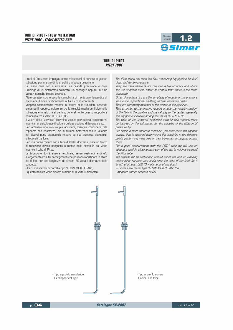
The Pitot tubes are used like flow measuring big pipeline for fluid clean and for low pressure. They are used where is not required a big accuracy and where the use of orifice plate, nozzle or Venturi tube would is too much expensive. Other characteristics are the simplicity of mounting, the pressure loss in line is practically anything and the contained costs. They are commonly mounted in the center of the pipelines. Take attention to the existing rapport among the velocity medium of the fluid in the pipeline and the velocity to the center; generally this rapport is inclusive among the values 0,83 to 0,85. The value of the “traverse” (technical term for this rapport) must be inserted in the calculation for the calculus of the differential pressure Δp. For obtain a more accurate measure, you need know this rapport exactly, that is obtained determining the velocities in the different points performing measures on two traverses orthogonal among them. For a good measurement with the PITOT tube we will use an adequate straight pipeline upstream of the tap in which is inserted the Pitot tube. The pipeline will be rectilinear, without strictures andl or widening andlor other obstacle that could alter the state of the fluid, for a length of at least 50D (D = diameter of the duct). - For the Flow meter type “FLOW METER BAR” this measure comes reduced at 8D.
I tubi di Pitot sono impiegati come misuratori di portata in grosse tubazione per misure di fluidi puliti e a bassa pressione. Si usano dove non è richiesta una grande precisione e dove l’impiego di un diaframma calibrato, un boccaglio oppure un tubo Venturi sarebbe troppo oneroso. Altre caratteristiche sono la semplicità di montaggio, la perdita di pressione di linea praticamente nulla e i costi contenuti. Vengono normalmente montati al centro delle tubazioni, tenendo presente il rapporto esistente tra la velocità media del fluido nella tubazione e la velocità al centro; generalmente questo rapporto e compreso tra i valori 0,83 a 0,85. Il valore della “traversa” (termine tecnico per questo rapporto) va inserita nel calcolo per il calcolo della pressione differenziale Δp. Per ottenere una misura più accurata, bisogna conoscere tale rapporto con esattezza, ciò si ottiene determinando le velocità nei diversi punti eseguendo misure su due traverse diametrali ortogonali tra loro. Per una buona misura con il tubo di PITOT dovremo usare un tratto di tubazione diritto adeguato a monte della presa in cui viene inserito il tubo di Pitot. La tubazione dovrà essere rettilinea, senza restringimenti e/o allargamenti e/o altri accorgimenti che possono modificare lo stato del fluido, per una lunghezza di almeno 50 volte il diametro della condotta. - Per i misuratori di portata tipo “FLOW METER BAR”, questa misura viene ridotta a meno di 8 volte il diametro.
- Tipo a profilo emisferico - Hemispherical type
- Tipo a profilo conico - Conical end type

Catalogue SA-2007 p. 35Ed. 05-07
TUBI DI PITOT - FLOW METER BARPITOT TUBE - FLOW METER BAR
SezioneSection 1.2
SezioneSection
1
SIMERSIMER
1/2”1/2”
V04CD-FFV04CD-FF F316F316
SIMERSIMER
F316F316
SIMERSIMER
1/2”1/2”
V04CD-FFV04CD-FF F316F316
SIMERSIMER
1/2”1/2”
V04CD-FFV04CD-FF F316F316
SIMERSIMER
SIMERSIMER
1/2”1/2”
V04CD-FFV04CD-FF F316F316
FLOW METER BAR TIPO ANNUBARFLOW METER BAR TYPE ANNUBAR
Flow meter bar
The primary device of measurement more advanced for liquid, gas and steam. The Flow meter bar is a primary instrument of measure, designed for produce a differential pressure, proportional to the flow.Based on the theorem of Bernoulli, the four upstream holes take the velocity of the flow in four different points of the pipe, the downstream hole measures the static pressure. The differential pressure that follows is proportional to the flow. The Flow meter bar measure liquids gas and steam in pipes or rectangular ducts accurately. Available for lines from DN 1” until above of the 10 feet (from 25 mm to above the 3 m). Available in many different models, each specifically designed for various applications in the measurement of the flow. Special models designed for hard conditions (contaminated fluid, high temperature, high pressure). Any it is the application or the installation, he preserve, precision in the measure for a long time, low permanente reduction of pressure, low cost of installation and maintenance, considerable energetic savings.
Flow meter bar
E’ il sensore primario di portata più avanzato per liquidi, gas e vapori. Il Flow meter bar e uno strumento di misura primario, progettato per produrre una pressione differenziale proporzionale alla portata. Basato sul teorema di Bernoulli, i fori, a monte, rilevano la velocità della portata in quattro punti differenti della tubazione, il foro a valle misura la pressione statica. La pressione differenziale che ne deriva è proporzionale alla portata.Il Flow meter bar misura accuratamente liquidi, gas e vapore in tubi o condotte rettangolari. Sono disponibili per linee da DN 1” fino sopra dei 30 piedi (da 25 mm a sopra i 3 m). E’ disponibile in molti modelli diversi, progettato per una gran varietà di applicazioni nelle misure di portata. Modelli speciali sono studiati per condizioni difficili (fluido contaminato, alte temperature, alte pressioni). Qualunque sia l’applicazione o l’installazione, esso mantiene, precisione nella misura per lungo tempo, minima perdita di pressione permanente, basso costo di installazione e manutenzione, notevoli risparmi energetici.
- Tipo estraibile con attacco al processo flangiato.
- Extraction type with shut-down device and flanged process connection
- Tipo fisso non estraibile dalla tubazione Attacco processo filettato
- Fixed tipe not extractable from pipe Threaded process connection
- Tipo fisso non estraibile dalla tubazione Attacco processo flangiato
- Fixed tipe not extractable from pipe Flanged process connection
- Tipo fisso non estraibile dalla tubazione adatto per tubazioni di piccole dimensioni.
- Fixed tipe in piping suitable for monting on small piping
ModelloModel:
075
Modello - Model: 073ModelloModel:074

TUBI DI PITOT - FLOW METER BARPITOT TUBE - FLOW METER BAR
SezioneSection 1.2
Catalogue SA-2007p. 36 Ed. 05-07
FLOW METER BAR TIPO ANNUBARFLOW METER BAR TYPE ANNUBAR
Precision in the measure
- Accuracy: ± 1.0% of the actual value of flow.- Repeatability: ± 0.1% of the actual value of flow.
The fluid when it finds an obstacle it divides in current fluid nearly uniforma.The sensor with round section produces a flow nearly uniform around to the sensor allowing a good precision in the measure of the differential pressure. The sensor with diamond section has been designed for have again high accuracy of the measure. Thanks to his form, around to the sensor, many uniform flows are produced, that allow a more precise measure of the differential pressure. The flow passing around the diamond section, creates a high pressure zone in front of the sensor of the velocity. This high pressure produces of the current fluid that been reflected from the particular conformation of the sensor.This type of sensor has been used with success with hard fluid, like those that transport sediments.
Long temi accuracy
The flow coefflcient of the Flow meter bar remams stable for a long term.The Flow meter bar is more precise than an orifice plate the long term. To each variation of the flow coefficient “K” than results a reduced accuracy. In the same break of time, to a constant coefficient of flow taken in our sensor it was found a change of the 10% of the factor ‘K” in a diaphragm orifice meter, that gives like result, a 10% of error in the reading of the flow. The accuracy of the diaphragm orifice meter, in the long term, it is subject to damages due to solid in suspension and/or formations of dirt or fat. These factors give as result an increase of the coefficient of flow “K”, that it takes the initial uncertainty from the 1% to the 10%- 20%.
Precisione nella misura
- Precisione ± 1.0% del valore attuale della portata.- Ripetersi ± 0.1% del valore attuale della portata.
Il fluido quando trova un ostacolo si divide in correnti fluide quasi uniformi. Il sensore con profilo rotondo produce un flusso quasi uniforme attorno al sensore permettendo una buona precisione nella misura della pressione differenziale.Il sensore con profilo a diamante e stato studiato per avere un’ancora più alta precisione della misura. Grazie alla sua forma, attorno al sensore, si producono dei flussi molto uniformi, che permettono una misura più precisa della pressione differenziale. Il flusso passando intorno al profilo a diamante crea una zona di alta pressione di fronte del sensore della velocità.Questa alta pressione produce delle correnti fluide che sono riflesse dalla particolare conformazione del sensore.Questo tipo di sensore e stato usato con successo con fluidi difficili, come quelli che trasportano sedimenti.
Precisione nel lungo termine
Il coefficiente di portata del Flow meter bar rimane stabile per un lungo termine.Il Flow meter bar e più preciso di un diaframma calibrato nel lungo termine.Ad ogni variazione del coefficiente di portata “K” ne consegue una riduzione di precisione. In un medesimo intervallo, ad un costante coefficiente di portata rilevato nel nostro sensore, si e stato riscontrato una variazione del 10% del fattore “K” in un diaframma calibrato, il quale dà come risultato, un 10% di errore nella lettura della portata. La precisione, di un diaframma nel lungo termine, è soggetta a danneggiamenti da parte di solidi in sospensione od a formazioni di sporcizia o di grasso.Questi fattori danno come risultato un incremento del coefficiente di portata “K” che porta l’incertezza iniziale dal 1% al 10% - 20%.
Flusso
Flow
Flusso
Flow
Sezione a diamante - Diamond section = D
1 - 2 = Attacco al processo filettato 1” NPT-M ANSI B1.20.1
completo di manicotto a saldare. Process connection threaded
1” NPT-M ANSI B1.20.1 complete of welding coupling.
Sezione a profilo rotondo - Round section = T
1F - 2F = Attacco al processo flangiato Dimensione flangia a richiesta.
Process connection flanged Size flange to client request

Catalogue SA-2007 p. 37Ed. 05-07
TUBI DI PITOT - FLOW METER BARPITOT TUBE - FLOW METER BAR
SezioneSection 1.2
SezioneSection
1
FLOW METER BAR TIPO ANNUBARFLOW METER BAR TYPE ANNUBAR
Applications The Flow meter bar thanks to the design and to the versatility of his models and materials, find employ in many applications: to water to air, to hard applications as contaminated and/or corrosive fluids, to lines of big sizes, to high temperatures and/or high pressure flows. Electric industries, Refinerles, Duct of gas, Chemical industries, Petrochemical, Aqueducts, use the flow-meter-bars. They are used besides in the energetic studies, in boiler control, pumps for water control, in air compressor control in control of consumption of conibustible, in process controls, in cooling, in steam heating, in the control of issues/contamination and in the airing of places and plants. The flow-meter-bar with extraction device is the best select in the complete line of primary devices. t is the only primary device of measurement of flow that could be installed, removed and reinstalled without the suspension of the productive activity of the system. It’s possible use the flow-meter-bar with ex- traction device on lines underground, without the need of permanente inspection well.
Technical specification- Standard material: AISI 316. - Available for pipelines from ND 2’’ to ND 60’’.
Flow meter bar is composed of four parts:1) The sensor of velocity with four pressure taps on the up-stream face.2) The interpolating tube inserted in the sensor of velocity, take the continuai average of the velocity of flow collected from the four pressure taps. This velocity of mean flow represents the more upstream velocity the static pressure line. 3) The back tap, downstream of the sense of the flow, take the low static pressure. 4) The two signals meet to the head of our sensor, complete of valves of intercept and from there sent to differential pressure primary instrument. The difference between high pressure from interpolating tube and the low pressure from the static tap is the differential pressure, that is proportional to the flow.
ApplicazioniIl Flow meter bar grazie agli studi fatti ed alla versatilità dei suoi modelli e materiali, trova impiego in moltissime applicazioni: dall’acqua all’aria, a difficili applicazioni, come fluidi contaminati e/o corrosivi, linee di grandi dimensioni, alte temperature e/o fluidi ad alta pressione. Industrie elettriche, Raffinerie, Gasdotti, in- dustrie Chimiche, Petrolchimiche, Acquedotti, usano i Flow meter bar. Sono usati inoltre negli studi energetici nel controllo di caldaie, di pompe per acqua, di compressori, nel controllo dei consumi di combustibile, nei controlli di processo, nel raffreddamento, nel riscaldamento del vapore, nel controllo di emissioni/inquinamento e nell’aerazione di luoghi ed impianti. Il Flow meter bar estraibile è la miglior scelta nella linea completa di dispositivi primari di portata. E’ il solo dispositivo primario di misura portata che può essere installato, rimosso e reinserito senza la sospensione dell’attività produttiva del sistema. E’ possibile usare il Flow meter bar estraibile su linee nel sottosuolo, senza il bisogno di pozzetti di accesso permanente.
Specifica tecnica- Materiale standard: AISI 316.- Disponibile per tubazioni da DN 2” a DN 60”.
Flow meter bar è composto di quattro parti base:1) Il sensore di velocità con quattro fori di presa di pressione sulla faccia a monte del senso del flusso. 2) Il tubo di interpolazione inserito nel sensore della velocità, rileva la media continua della velocità della portata raccolta dalle quattro prese. Questa velocità di portata media rappresenta la velocità a monte più la pressione statica in linea. 3) Il foro di presa posteriore, posta a valle del senso del flusso, rileva la bassa pressione statica. 4) I due segnali confluiscono alla testa del nostro sensore, completa di valvole di intercettazione e da qui vengono inviati allo strumento primario a pressione differenziale. La differenza tra la pressione alta dal tubo di interpolazione e la pressione bassa dalla presa statica e la pressione differenziale, che è proporzionale alla portata.
Velocità mediaVelocity average
SIMERSIMER
1/2”1/2”
V04CD-FFV04CD-FF F316F316
SIMERSIMER
1/2”1/2”
V04CD-FFV04CD-FF F316F316
SIMERSIMER
F316F316
Velocità mediaVelocity average
4
3
1
2
Valvole a spillo - Needle valves = N
Valvole a sfera - ball valves = B
D
2 x D

TUBI DI PITOT - FLOW METER BARPITOT TUBE - FLOW METER BAR
SezioneSection 1.2
Catalogue SA-2007p. 38 Ed. 05-07
FLOW METER BAR TIPO ANNUBARFLOW METER BAR TYPE ANNUBAR
Low costs of installationThe easy and fast complete installation offers a consideratele saving of times and costs.The reduced weight is a notable help for assemblage.For mounting you need only weld on pipeline a half-coupling or a flanged branch.
Installation in 90° elbow The straight length at least upstream or downstream of pipe that need for a near installation to 90° elbow of a primary element, is often one of the motives of cost for primary devices. The flow-meter-bar could be installed downstream a 90° elbow without affect on the measure. This involves considerable savings in costs of pipeline and new and more flexible criterions of design.
Low cost o clean and maintenanceThe installation is easy and clean respect to the other devices of measure. Of consequence also the times of clean of the pipeline has been reduced notably. The saving is calculated among the 25% and the 70% of the costs in function of the dimension of the flow-meter-bar. The model with extraction device could be removed without the suspension of the activity of the system, allowing an easy inspection and clean of the same.
Advantages - Low reduction of pressure in line.- Small costs of assemblage.- Versatility in the models.- Precision in the measure.- Low costs of design of the pipeline. - Low cost of maintenance.
Basso costo di installazioneLa facile e veloce installazione completa offre un notevole risparmio di tempi e di costi.Il peso ridotto fa risparmiare in tempo di montaggio.Per il montaggio, necessita solamente saldare in tubazione, un mezzo manicotto oppure bocchello flangiato.
Installazione in curva a 90° La lunghezza diritta minima a monte ed a valle, richiesta per un’installazione vicino ad una curva a 90°, di un elemento primario è spesso uno dei motivi di costo per la maggioranza dei dispositivi di misura della portata. Il Flow meter bar può essere installato a valle di una curva a 90° senza pregiudicare la misura. Questo comporta risparmi considerevoli in costi di tubazione ed a nuovi e più flessibili criteri di progettazione.
Basso costo di pulizia e manutenzioneI Flow meter bar eliminano molti dei problemi di start-up dovuti a sporcizia all’interno dei tubi, permettendo una facile pulizia della tubazione dopo l’installazione. Di conseguenza anche i tempi di pulizia si sono ridotti notevolmente. Il risparmio e calcolato tra il 25% ed il 70% dei costi in funzione della dimensione del Flow meter bar. Il modello estraibile può essere rimosso senza la sospensione dell’attività del sistema, permettendo una facile ispezione e pulizia dello stesso.
Vantaggi - Bassa perdita di pressione in linea.- Minori costi di montaggio.- Versatilità nei modelli.- Precisione nella misura.- Minor costi di progettazione della tubazione.- Bassi costi di manutenzione.
Come ordinare: FLOW METER BAR TIPO ANNUBAR - How to order: FLOW METER BAR TYPE ANNUBAR
-- DProfilo Profile
D - Prof. diamanteDiamond section
T - Profilo tondoRound section
1Attacchi processo
Process connection
1 - 1” NPT-M2 - 1”1/2 NPT-M
1F - 1” ANSI 300 RF2F - 1”1/2 ANSI 300 RF
NTipo valvole Valves type
N - Valvole spillo Needle valves
B -Valvole a sfera Ball valves
4Attacchi valvole Valves connection
2 - 1/2” NPT-F4 - 1/4” NPT-F
0Supporto
finale Support end
0 - Assente No support
1 - Filettato Threaded
2 - Flangiato Flanged
16MaterialiMaterial
16 - AISI 31600 - Altri-Other
075Tipo / Modello Type / Model
073 - 1”1/2 to 4”Fisso - Fixed
074 - Over 6”Fisso - Fixed
075 - Over 6”Estraibile -Extraction device
- - - - -