Embed Size (px)
Citation preview
AAPM 2011 Summit on CT Dose
Tube Current Modulation Approaches:
Overview, Practical Issues and Potential Pitfalls
Michael McNitt-Gray, PhD, DABR, FAAPM
Professor, Department of Radiology
Director, UCLA Biomedical Physics Graduate Program
David Geffen School of Medicine at UCLA
(with help from Dianna Cody, PhD and Jim Kofler, PhD)
AAPM 2011 Summit on CT Dose
Tube Current Modulation - Overview
• Basic Idea:
– Adapt Tube Current to Attenuation of Body Region
– Increase Tube Current for more attenuating area
– Decrease Tube Current for less attenuating area
• Overall Goal: Reduce dose yet maintain image quality
AAPM 2011 Summit on CT Dose
Tube Current Modulation - Implementations
• (Adapted from McCollough et al Radiographics, 2006)
• How is the tube current modulated:
– Based on measured attenuation or a sinusoidal-type function.
– Preprogrammed, implemented in near-real time by using a
feedback mechanism, or a combination of these two
– Only angularly around the patient, along the long axis of the
patient, or both.
– To allow use of one of several algorithms to automatically
adjust the current to achieve the desired image quality..
AAPM 2011 Summit on CT Dose
Tube Current Modulation Methods
• Several Flavors
–Angular modulation (in plane (x-y) )
– Longitudinal modulation (along patient length, z-axis)
–Combination (x, y and z) modulation
–Temporal (ECG-gated) modulation
AAPM 2011 Summit on CT Dose
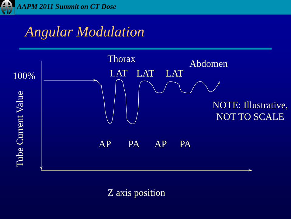
Angular Modulation
Z axis position
Tube
Curr
ent
Val
ue
Thorax Abdomen
100%
AP PA
LAT LAT
AP PA
LAT
NOTE: Illustrative,
NOT TO SCALE
AAPM 2011 Summit on CT Dose
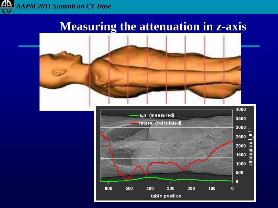
Measuring the attenuation in z-axis
AAPM 2011 Summit on CT Dose
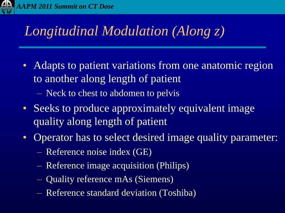
Longitudinal Modulation (Along z)
• Adapts to patient variations from one anatomic region
to another along length of patient
– Neck to chest to abdomen to pelvis
• Seeks to produce approximately equivalent image
quality along length of patient
• Operator has to select desired image quality parameter:
– Reference noise index (GE)
– Reference image acquisition (Philips)
– Quality reference mAs (Siemens)
– Reference standard deviation (Toshiba)
AAPM 2011 Summit on CT Dose
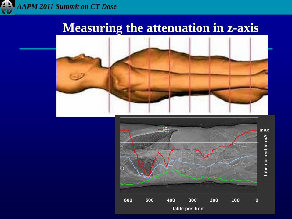
Measuring the attenuation in z-axis
0100200300400500600
table position
tub
e c
urr
en
t in
mA
a.p.lateralmean max
AAPM 2011 Summit on CT Dose
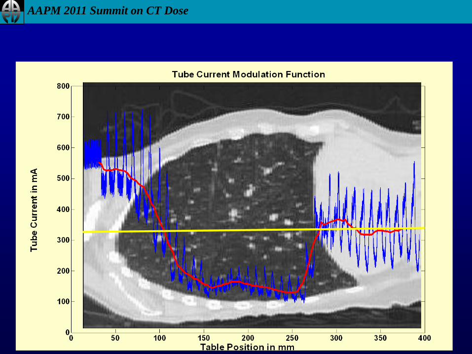
Combination (x,y and z)
• Adapts to patient size
• Adapts to variation from one anatomic region to
another along length of patient and in plane
• Low frequency changes across anatomic regions (z)
• High frequency changes across angular variations (x,y)
AAPM 2011 Summit on CT Dose
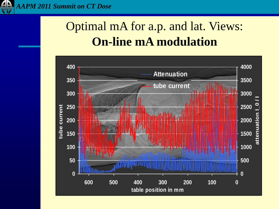
0
500
1000
1500
2000
2500
3000
3500
4000
0100200300400500600
table position in mm
att
en
uati
on
I_0 / I
0
50
100
150
200
250
300
350
400tu
be c
urr
en
t
Attenuation
tube current
Optimal mA for a.p. and lat. Views:
On-line mA modulation
AAPM 2011 Summit on CT Dose
AAPM 2011 Summit on CT Dose
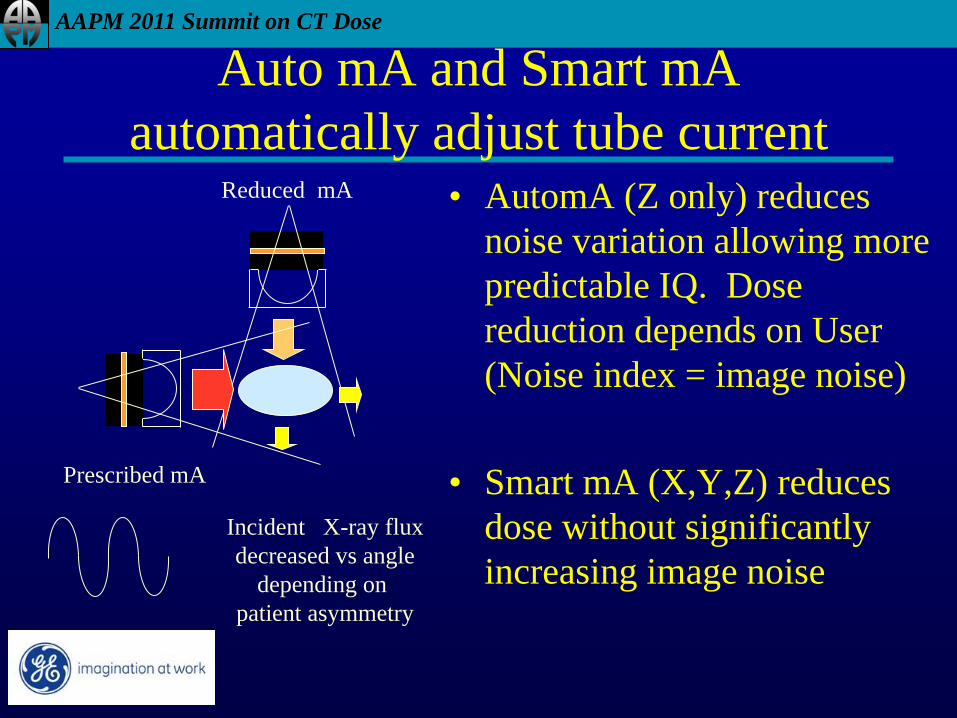
Auto mA and Smart mA
automatically adjust tube current • AutomA (Z only) reduces
noise variation allowing more
predictable IQ. Dose
reduction depends on User
(Noise index = image noise)
• Smart mA (X,Y,Z) reduces
dose without significantly
increasing image noise
Incident X-ray flux
decreased vs angle
depending on
patient asymmetry
Prescribed mA
Reduced mA
AAPM 2011 Summit on CT Dose
Implementation Issues
• How to measure patient attenuation?
• Primarily from Scout/Topogram/Surview/Scanogram
– (aka CT radiograph or planning view)
• How is tube current modulated?
– Siemens and Philips adjust tube current based on online
feedback (measurements from previous 180 degree views)
– Others do predictive calculation or sinusoidal interpolation
between AP and Lateral views

AAPM 2011 Summit on CT Dose
Att’n
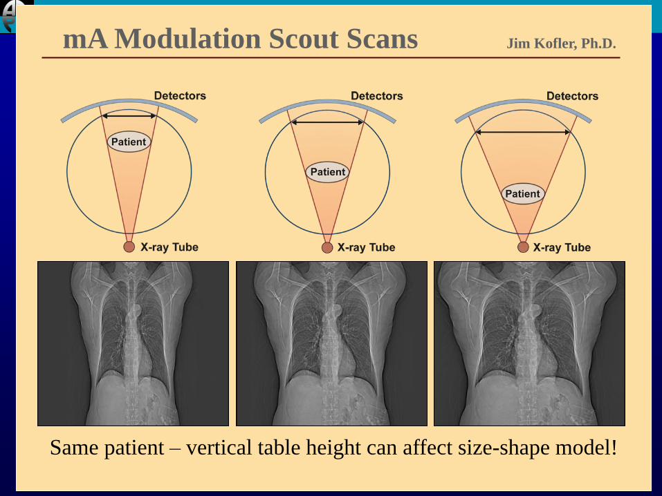
Use of Scout Image for Modulation
Patient size & shape Patient size & shape
AAPM 2011 Summit on CT Dose
mA Modulation Scout Scans Jim Kofler, Ph.D.
Same patient – vertical table height can affect size-shape model!
AAPM 2011 Summit on CT Dose
Bottom Line
• Tube current modulation REQUIRES CAREFUL
CENTERING OF THE PATIENT IN THE
GANTRY
AAPM 2011 Summit on CT Dose
How do scouts affect the resulting helical dose
when TCM is used?
• kVp mismatch between scout and helical?
• A/P vs P/A scout?
• P/A vs lateral scout?
AAPM 2011 Summit on CT Dose
Methods
• GE VCT
• Adult Chest Phantom
• Adult acrylic abdomen/pelvis phantom
• Ran various scout options
• Planned helical scans according to our protocol
• Used predicted CTDIvol values to compare dose for
each scout option
AAPM 2011 Summit on CT Dose
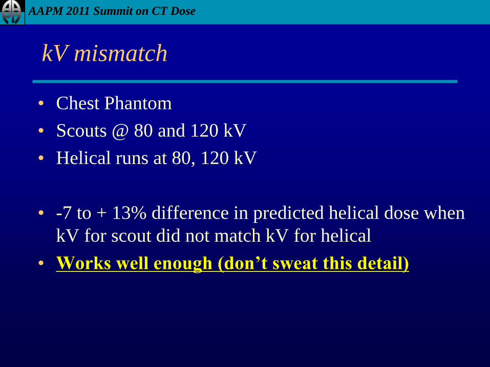
kV mismatch
• Chest Phantom
• Scouts @ 80 and 120 kV
• Helical runs at 80, 120 kV
• -7 to + 13% difference in predicted helical dose when
kV for scout did not match kV for helical
• Works well enough (don’t sweat this detail)
AAPM 2011 Summit on CT Dose
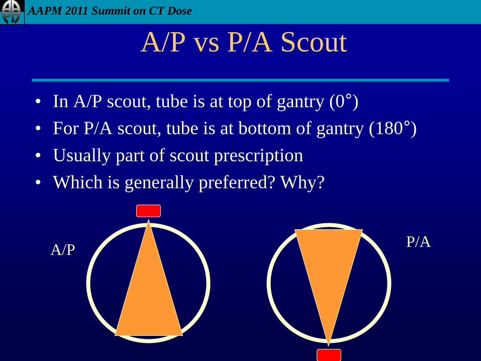
A/P vs P/A Scout
• In A/P scout, tube is at top of gantry (0°)
• For P/A scout, tube is at bottom of gantry (180°)
• Usually part of scout prescription
• Which is generally preferred? Why?
A/P P/A
AAPM 2011 Summit on CT Dose
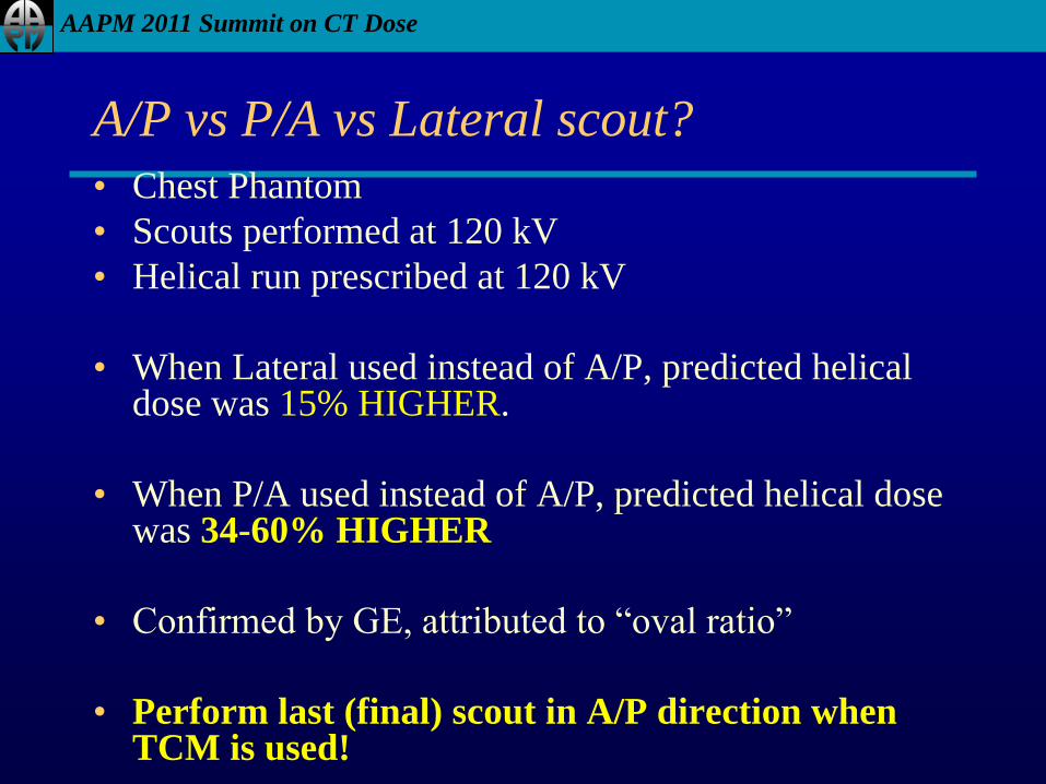
A/P vs P/A vs Lateral scout?
• Chest Phantom
• Scouts performed at 120 kV
• Helical run prescribed at 120 kV
• When Lateral used instead of A/P, predicted helical dose was 15% HIGHER.
• When P/A used instead of A/P, predicted helical dose was 34-60% HIGHER
• Confirmed by GE, attributed to “oval ratio”
• Perform last (final) scout in A/P direction when TCM is used!
AAPM 2011 Summit on CT Dose
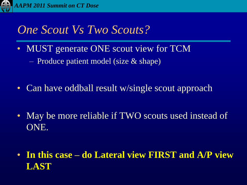
One Scout Vs Two Scouts?
• MUST generate ONE scout view for TCM
– Produce patient model (size & shape)
• Can have oddball result w/single scout approach
• May be more reliable if TWO scouts used instead of
ONE.
• In this case – do Lateral view FIRST and A/P view
LAST
AAPM 2011 Summit on CT Dose
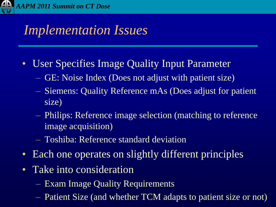
Implementation Issues
• User Specifies Image Quality Input Parameter
– GE: Noise Index (Does not adjust with patient size)
– Siemens: Quality Reference mAs (Does adjust for patient
size)
– Philips: Reference image selection (matching to reference
image acquisition)
– Toshiba: Reference standard deviation
• Each one operates on slightly different principles
• Take into consideration
– Exam Image Quality Requirements
– Patient Size (and whether TCM adapts to patient size or not)
AAPM 2011 Summit on CT Dose
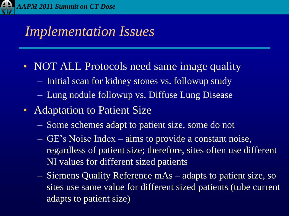
Implementation Issues
• NOT ALL Protocols need same image quality
– Initial scan for kidney stones vs. followup study
– Lung nodule followup vs. Diffuse Lung Disease
• Adaptation to Patient Size
– Some schemes adapt to patient size, some do not
– GE’s Noise Index – aims to provide a constant noise,
regardless of patient size; therefore, sites often use different
NI values for different sized patients
– Siemens Quality Reference mAs – adapts to patient size, so
sites use same value for different sized patients (tube current
adapts to patient size)
AAPM 2011 Summit on CT Dose
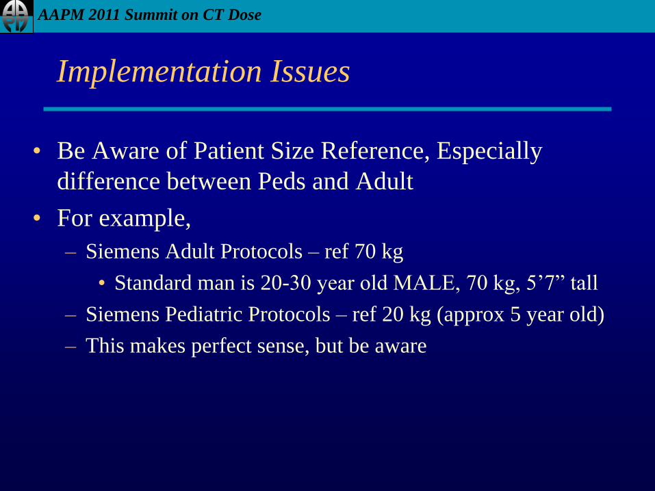
Implementation Issues
• Be Aware of Patient Size Reference, Especially
difference between Peds and Adult
• For example,
– Siemens Adult Protocols – ref 70 kg
• Standard man is 20-30 year old MALE, 70 kg, 5’7” tall
– Siemens Pediatric Protocols – ref 20 kg (approx 5 year old)
– This makes perfect sense, but be aware
AAPM 2011 Summit on CT Dose
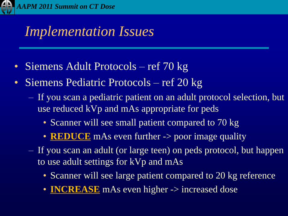
Implementation Issues
• Siemens Adult Protocols – ref 70 kg
• Siemens Pediatric Protocols – ref 20 kg
– If you scan a pediatric patient on an adult protocol selection, but
use reduced kVp and mAs appropriate for peds
• Scanner will see small patient compared to 70 kg
• REDUCE mAs even further -> poor image quality
– If you scan an adult (or large teen) on peds protocol, but happen
to use adult settings for kVp and mAs
• Scanner will see large patient compared to 20 kg reference
• INCREASE mAs even higher -> increased dose
AAPM 2011 Summit on CT Dose
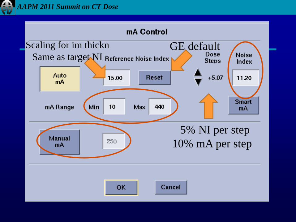
5% NI per step
10% mA per step
GE default Scaling for im thickn
Same as target NI
AAPM 2011 Summit on CT Dose
Other parameters
• Reference Noise Index
– Scales NI for image thickness change
– Difficult to understand
– Backup – set equal to Noise Index value
• mA window
– Set min mA carefully (100 mA min for adults?)
– Set max mA carefully (500 mA max for adults?)
• Manual mA
– Set this value for typical patient size!!!
AAPM 2011 Summit on CT Dose
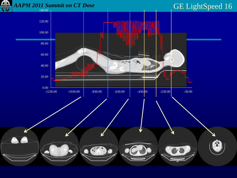
0.00
20.00
40.00
60.00
80.00
100.00
120.00
140.00
-1230.00 -1030.00 -830.00 -630.00 -430.00 -230.00 -30.00
GE LightSpeed 16
AAPM 2011 Summit on CT Dose
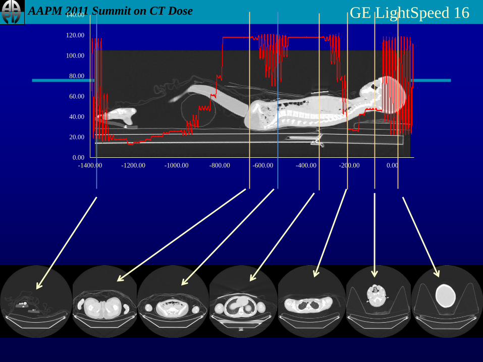
0.00
20.00
40.00
60.00
80.00
100.00
120.00
140.00
-1400.00 -1200.00 -1000.00 -800.00 -600.00 -400.00 -200.00 0.00
GE LightSpeed 16
AAPM 2011 Summit on CT Dose
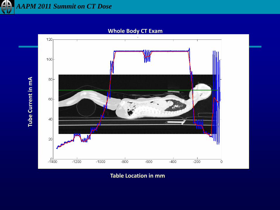
Whole Body CT Exam
Table Location in mm
Tub
e C
urr
en
t in
mA
Table Location in mm
AAPM 2011 Summit on CT Dose
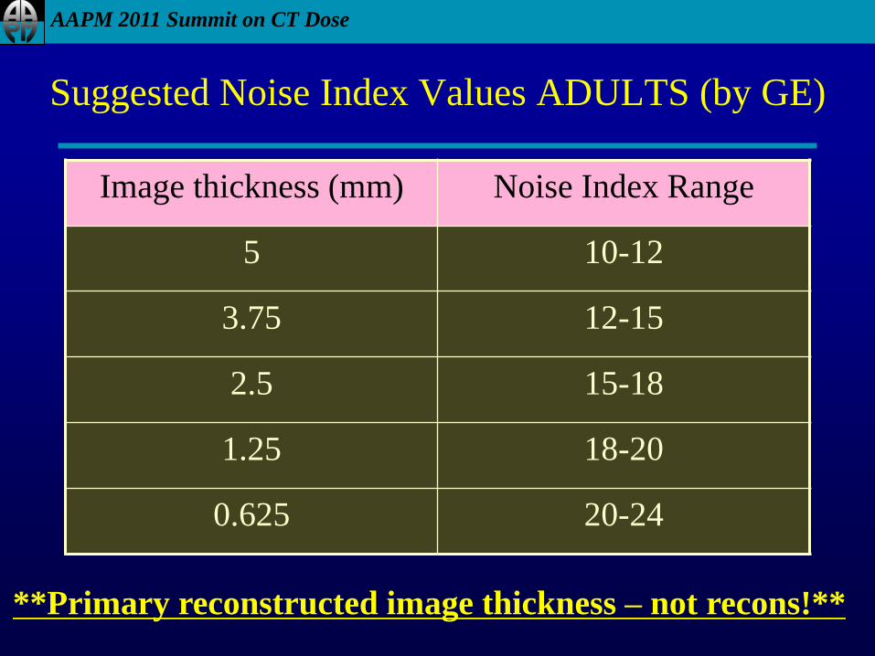
Suggested Noise Index Values ADULTS (by GE)
Image thickness (mm) Noise Index Range
5 10-12
3.75 12-15
2.5 15-18
1.25 18-20
0.625 20-24
**Primary reconstructed image thickness – not recons!**
AAPM 2011 Summit on CT Dose
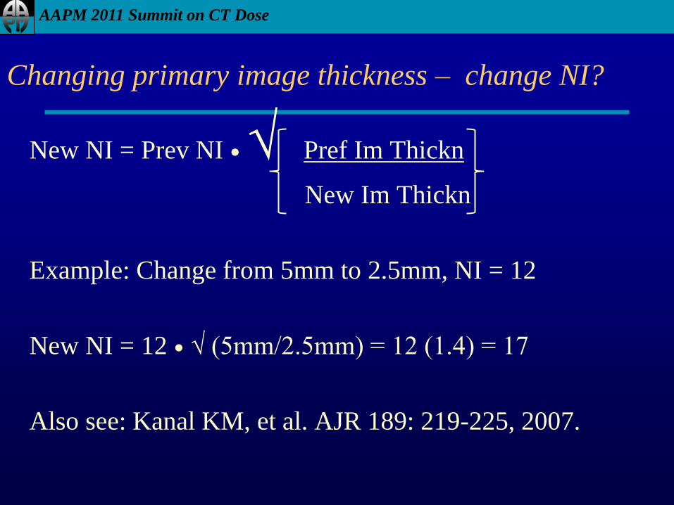
Changing primary image thickness – change NI?
New NI = Prev NI ● √ Pref Im Thickn
New Im Thickn
Example: Change from 5mm to 2.5mm, NI = 12
New NI = 12 ● √ (5mm/2.5mm) = 12 (1.4) = 17
Also see: Kanal KM, et al. AJR 189: 219-225, 2007.
AAPM 2011 Summit on CT Dose
So what is TCM good for?
• Right sizing for patient habitus
– Automatically sets technique for variable size patients
– Body: Pediatrics, Adults of all sizes
– PET/CT
• Adjusting mA for cross section size & shape
– Head – to neck – to shoulders
– Shoulders!
– Chest – Abdomen – Pelvis (attenuation changes)
– Attenuation correction scans (Hybrid scanners)
AAPM 2011 Summit on CT Dose
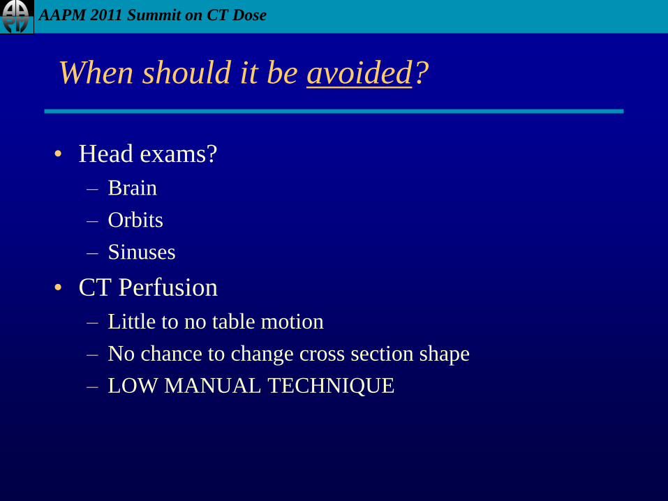
When should it be avoided?
• Head exams?
– Brain
– Orbits
– Sinuses
• CT Perfusion
– Little to no table motion
– No chance to change cross section shape
– LOW MANUAL TECHNIQUE
AAPM 2011 Summit on CT Dose
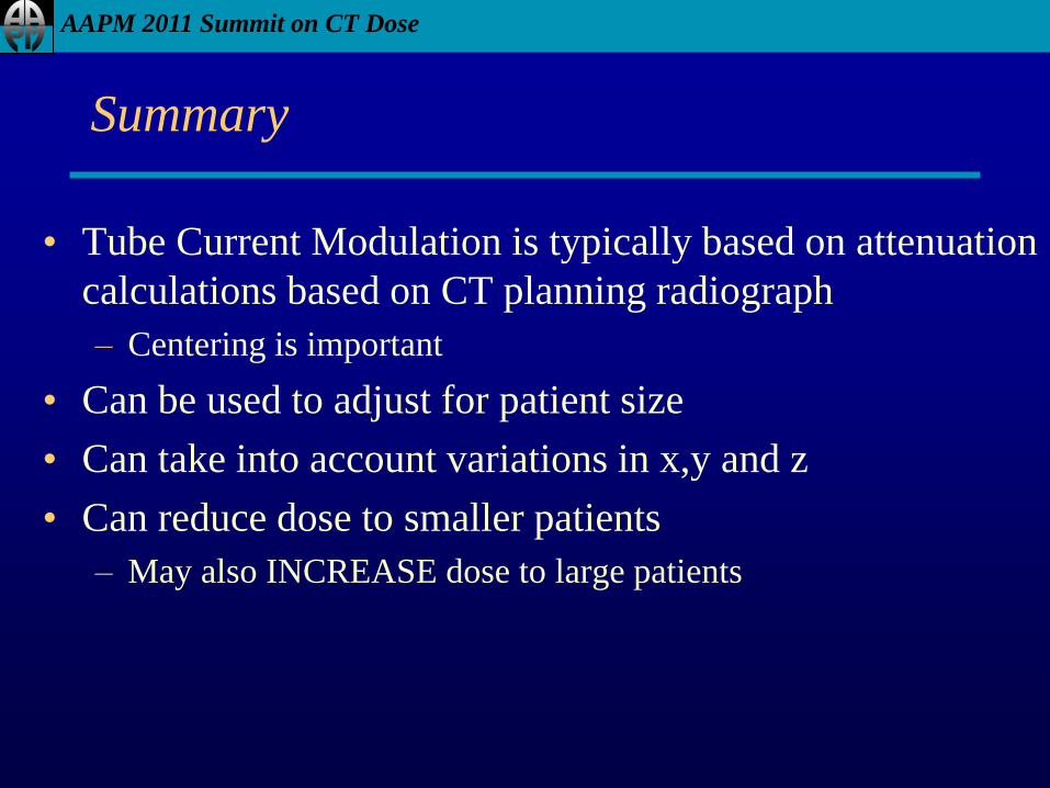
Summary
• Tube Current Modulation is typically based on attenuation
calculations based on CT planning radiograph
– Centering is important
• Can be used to adjust for patient size
• Can take into account variations in x,y and z
• Can reduce dose to smaller patients
– May also INCREASE dose to large patients
AAPM 2011 Summit on CT Dose
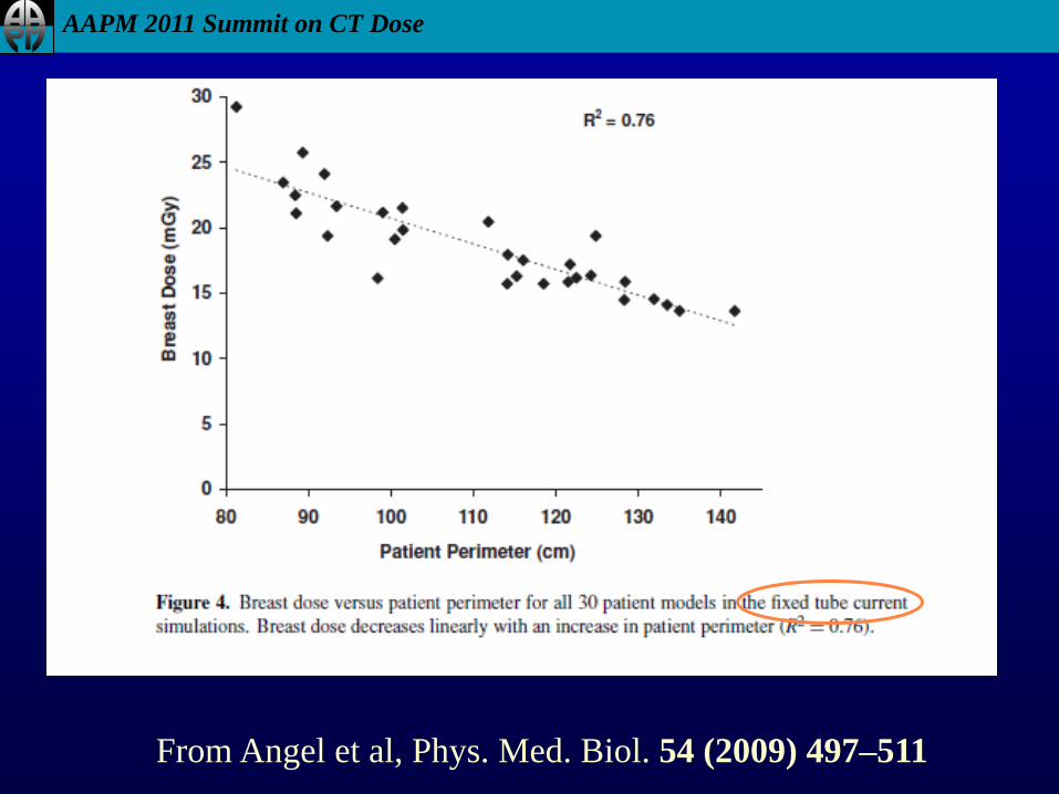
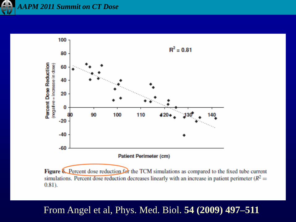
From Angel et al, Phys. Med. Biol. 54 (2009) 497–511
AAPM 2011 Summit on CT Dose
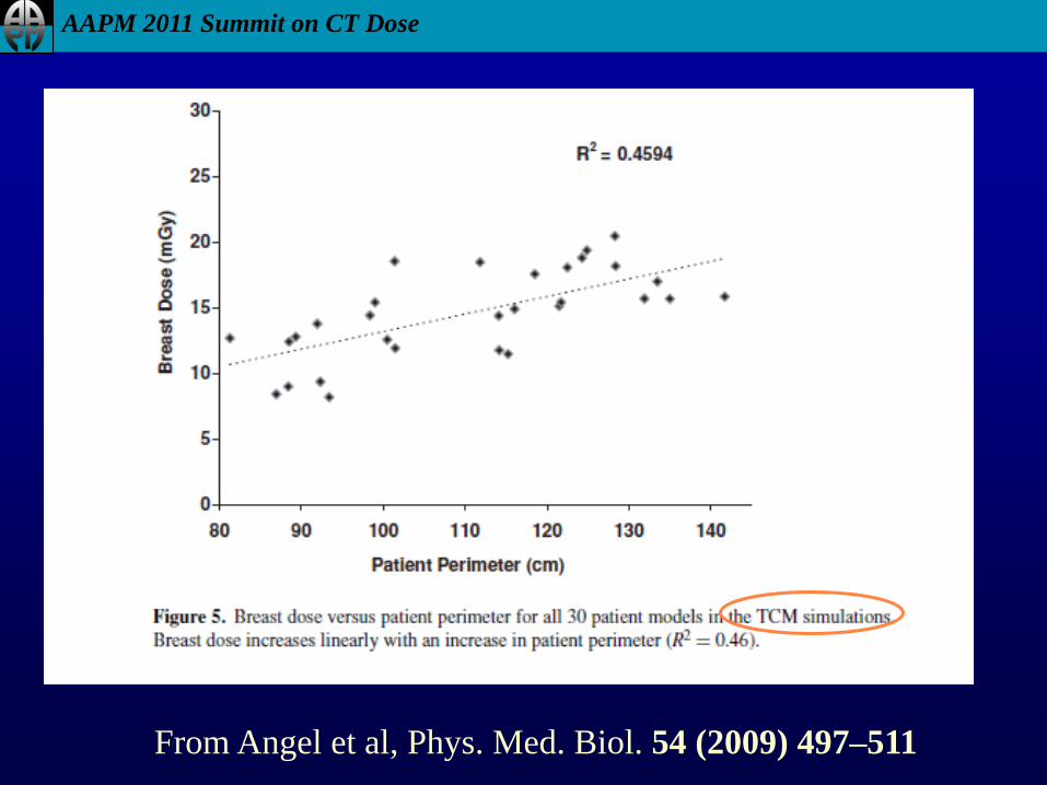
From Angel et al, Phys. Med. Biol. 54 (2009) 497–511
AAPM 2011 Summit on CT Dose
From Angel et al, Phys. Med. Biol. 54 (2009) 497–511
AAPM 2011 Summit on CT Dose
Summary
• User Inputs Image Quality Parameter
• This has SIGNIFICANT effect on TCM
• Should be chosen based on:
– Image Quality Requirements
– Patient Size adjustments – and knowledge of how
manufacturer’s TCM does or does not adjust for size
• i.e. whether TCM adjusts for size
• or user has to adjust input value based on patient size