Embed Size (px)
Citation preview

1
Tuaspring Sea Water Desalination with CCPP in Singapore: An
Example for Sustainable Power Generation
Authors:
Camille Hurn
Hyflux Ltd., Senior Vice President, Energy & Infrastructure Development
Thomas Hagedorn
Siemens Energy, Vice President Sales, GT Power Plant Solutions Asia, Pacific
PowerGen Asia
Bangkok, October 3 – 5, 2012

2
Abstract
The Asian countries have some of the fastest growing populations, leading to massive
challenges in urban areas. Huge long-term investments in infrastructure are needed,
especially in power generation, potable water, buildings, and mobility.
Sustainability for the Asia region requires the creation of a fully integrated and electricity-
based energy system. The first steps towards lasting economic growth and social welfare
have already been taken. A good example is the Tuaspring seawater desalination and
combined-cycle power plant (CCPP) project in Singapore, which Hyflux is developing on
a Design, Build, Own & Operate basis. When completed in 2013, the seawater reverse
osmosis (SWRO) desalination plant will add 318,500 cubic metres of desalinated water to
Singapore’s water supply. Incorporated into the project is a high-efficiency 411MW
nameplate-capacity CCPP supplied by Siemens, which will supply power to the SWRO
desalination plant, with excess electricity being sold into Singapore’s competitive
electricity market.
This paper will describe the challenges and special needs of cities using the example of
Singapore and will present the enormous challenge posed by the growth of urban
infrastructure approaching its limits. The consumption of natural resources is also
particularly high in cities; they account for two thirds of our global energy demand and
for up to 70 percent of the greenhouse gases. An energy-efficient and sustainable
infrastructure is urgently required. This is the only way to maintain quality of life in cities,
ensure competitiveness, and at the same time protect natural resources and the
environment. In this paper the solutions worked out by the Hyflux and Siemens teams
to build the first Integrated Water and Power Plant in South East Asia are described in
detail.
Tuaspring is Singapore’s largest municipal desalination plant. The plant will use Hyflux’s
proprietary Kristal® ultrafiltration (UF) membrane technology for the pre-treatment
process followed by a double pass reverse osmosis (RO) system to produce water for
domestic and industrial use. Tuaspring features the second largest UF membrane
installation after the 500,000 m3/day Magtaa Desalination Plant in Algeria, the world’s
largest membrane-based desalination plant, also built by Hyflux. Kristal® UF
3
membranes are designed and developed to effectively remove suspended solids, micro-
organisms and bacteria from raw water. It is the first UF membrane to achieve NSF
certification for removal of cryptosporidium. As well as its use in providing safe drinking
water, the Kristal® UF membrane provides a high quality SWRO pre-treatment solution,
enhancing the performance and extending the lifespan of the downstream RO
membranes, thereby consuming less chemicals and energy.
To further improve the operational cost efficiency and provide a better return on
investment, the high efficiency Siemens F Class CCPP was selected to provide electricity
for the SWRO plant as well as to the Singapore electricity market. By combining the two
plants, significant capital and operating cost synergies have been obtained.
The Singapore Water Story is a compelling one, on how a small island, with no natural
aquifers and covering only 714 square kilometres has been able to overcome various
challenges such as a lack of natural water bodies, drought, floods and water pollution to
build a robust and diversified supply of water to serve its population and industries.
Currently Singapore relies on four sources of water, namely, local catchment water,
imported water, highly purified reclaimed water known as NEWater and desalinated
water.
Today, Singapore’s water demand is about 1,730,000 cubic metres a day. This amount is
expected to double in the next 50 years, with about 70% of the demand coming from the
non-domestic sector and domestic consumption making up the other 30%. To meet the
long-term water needs of Singapore, the total water catchment area in Singapore will be
increased to 90% of total land area from the current two-thirds. Concurrently other
sources of water will grow as well. By 2060, the current NEWater capacity will be tripled
so that NEWater can meet 50% of future water demand. There is also the intention to
ramp up desalination capacity by almost 10 times so that desalinated water will meet at
least 30% of water demand1.
As well as the challenges Singapore faces in meeting its water needs, the island also lacks
natural energy sources and must import its raw energy needs. Historically, the power
industry in Singapore was thermal-based, fired with high sulphur fuel oil (HSFO). In
recent years though the industry has been migrating towards more environmentally-
4
friendly natural gas as its fuel source. Piped natural gas is currently imported from
Malaysia and Indonesia. However, with increased regional needs for energy resulting
from economic growth, Singapore needs to both widen its sourcing of energy and ensure
that energy is used efficiently. To this end, the Singapore Government announced in
2006 that it would build an LNG (Liquefied Natural Gas) terminal to import LNG. The
LNG import terminal is due to commence operations in 2013. The Siemens CCPP
incorporated into the Tuaspring project will use regasified LNG as its primary fuel.
Using a single-shaft configuration, it will be one of the most efficient electricity
generators in the country when completed in 2014, thus making an important
contribution to Singapore’s energy sustainability.
.

5
Table of contents
1. The challenge – Combining Water with Efficient Power Production ........................................................................................6
2. The solution......................................................................................8
2.1. Overview of the desalination plant.......................................................................................8
2.2. Overview of the power plant ................................................................................................9
2.3. Water Integration ..................................................................................................................18
2.4. Layout .....................................................................................................................................18
2.5. Electrical Integration ............................................................................................................21
3. Flexibility........................................................................................23
4. Project Execution ...........................................................................27
4.1. Project Management .............................................................................................................27
4.2. Project Control ......................................................................................................................28
4.3. Environment, Health and Safety ........................................................................................29
5. Conclusion......................................................................................30
6. References ...................................................................................... 31
7. Copyright ........................................................................................32
8. Disclaimer ......................................................................................32
6
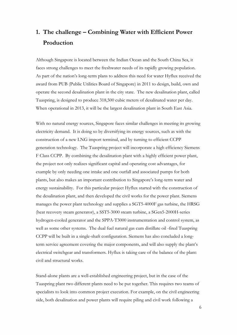
1. The challenge – Combining Water with Efficient Power
Production
Although Singapore is located between the Indian Ocean and the South China Sea, it
faces strong challenges to meet the freshwater needs of its rapidly growing population.
As part of the nation’s long-term plans to address this need for water Hyflux received the
award from PUB (Public Utilities Board of Singapore) in 2011 to design, build, own and
operate the second desalination plant in the city state. The new desalination plant, called
Tuaspring, is designed to produce 318,500 cubic meters of desalinated water per day.
When operational in 2013, it will be the largest desalination plant in South East Asia.
With no natural energy sources, Singapore faces similar challenges in meeting its growing
electricity demand. It is doing so by diversifying its energy sources, such as with the
construction of a new LNG import terminal, and by turning to efficient CCPP
generation technology. The Tuaspring project will incorporate a high efficiency Siemens
F Class CCPP. By combining the desalination plant with a highly efficient power plant,
the project not only realizes significant capital and operating cost advantages, for
example by only needing one intake and one outfall and associated pumps for both
plants, but also makes an important contribution to Singapore’s long-term water and
energy sustainability. For this particular project Hyflux started with the construction of
the desalination plant, and then developed the civil works for the power plant. Siemens
manages the power plant technology and supplies a SGT5-4000F gas turbine, the HRSG
(heat recovery steam generator), a SST5-3000 steam turbine, a SGen5-2000H-series
hydrogen-cooled generator and the SPPA-T3000 instrumentation and control system, as
well as some other systems. The dual fuel natural gas cum distillate oil -fired Tuaspring
CCPP will be built in a single-shaft configuration. Siemens has also concluded a long-
term service agreement covering the major components, and will also supply the plant’s
electrical switchgear and transformers. Hyflux is taking care of the balance of the plant:
civil and structural works.
Stand-alone plants are a well-established engineering project, but in the case of the
Tuaspring plant two different plants need to be put together. This requires two teams of
specialists to look into common project execution. For example, on the civil engineering
side, both desalination and power plants will require piling and civil work following a

7
comprehensive regulatory approval procedure. Thereafter building works, mechanical,
piping work and electrical works follows. The key difference between the two plants is
that one requires the use of membranes and the other requires the use of natural gas. The
mechanical parts are different, but the execution in terms of project management and
project execution is quite similar.
8
2. The solution
2.1. Overview of the desalination plant
Tuaspring is Singapore’s largest municipal desalination plant. The key technology that
will be employed in the desalination process is reverse osmosis (RO), whereby seawater is
forced against semi-permeable RO membranes under pressure in a continuous flow
condition to separate salts from water. When completed in 2013, the plant will add
318,500 cubic metres of desalinated water to Singapore’s water supply. The water
produced will be for domestic and industrial use.
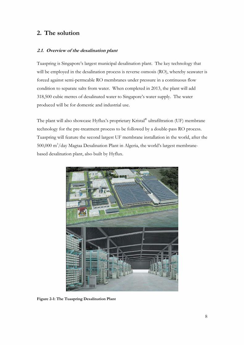
The plant will also showcase Hyflux’s proprietary Kristal® ultrafiltration (UF) membrane
technology for the pre-treatment process to be followed by a double-pass RO process.
Tuaspring will feature the second largest UF membrane installation in the world, after the
500,000 m3/day Magtaa Desalination Plant in Algeria, the world’s largest membrane-
based desalination plant, also built by Hyflux.
Figure 2-1: The Tuaspring Desalination Plant
9
Hyflux’s Kristal® UF membranes, the first to achieve NSF certification for removal of
cryptosporidium, are well suited for SWRO pre-treatment. Kristal® UF membranes act as
an effective barrier to suspended solids and micro-organisms, ensuring stable, high
quality, feed water to be delivered to the RO membranes, thereby enhancing the
performance and extending the lifespan of the RO system.
The Tuaspring desalination plant has the following main features:
- 25 Years’ Water Purchase Agreement with PUB (Public Utilities Board of Singapore)
- Capacity: 318,500 m³/d
- Expected completion 2013
2.2. Overview of the power plant
For the Tuaspring CCPP the Siemens proven single shaft concept has been applied
which has at site ambient conditions a power output of > 390 MW and a net efficiency
of 58.5 %. The following main features apply:
- Single shaft configuration
- Gas turbine SGT5-4000F fired with natural gas (re-gasified LNG) and distillate oil as emergency back-up fuel
- Steam turbine SST5-3000 with axially installed condenser, coupled to the generator by Syncro-Self-Shifting clutch (SSS)
- Common hydrogen cooled generator SGen5-2000H for the steam & gas turbine
- Triple pressure reheat heat recovery steam generator
- Plant control systems (SPPA-T3000)
- Power Control Centers and electrical equipment like Isolated Phase Bus Duct, generator circuit breaker, DC-components and switchgears
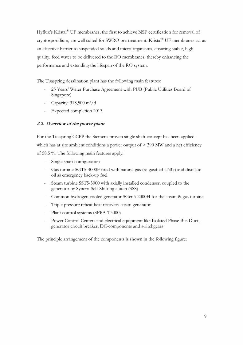
The principle arrangement of the components is shown in the following figure:
10
Figure 2-2 The Siemens Single Shaft – Schematic Drawing
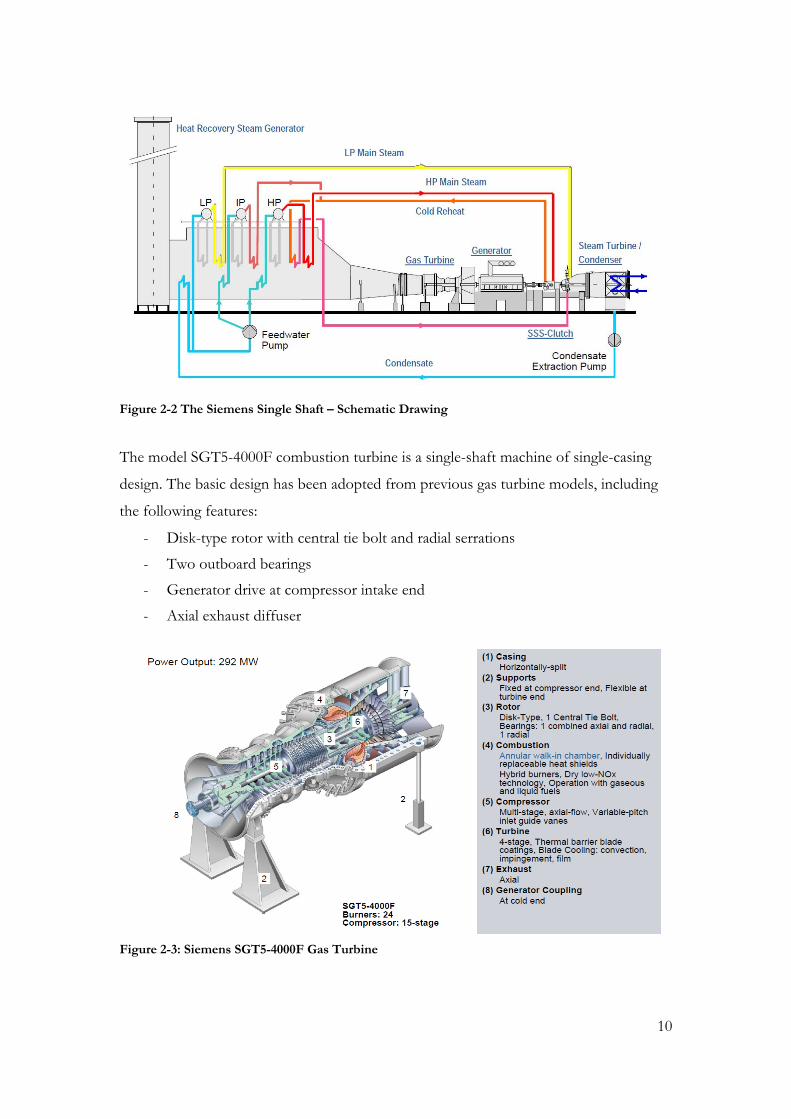
The model SGT5-4000F combustion turbine is a single-shaft machine of single-casing
design. The basic design has been adopted from previous gas turbine models, including
the following features:
- Disk-type rotor with central tie bolt and radial serrations
- Two outboard bearings
- Generator drive at compressor intake end
- Axial exhaust diffuser
Figure 2-3: Siemens SGT5-4000F Gas Turbine

11
The rotor is supported by two bearings. A combined journal and thrust bearing is located
at the inlet side of the compressor, and a journal bearing at the exhaust side of the
turbine.
The rotor is an assembly of disks, each carrying one row of blades, and hollow shaft
sections, all held together by a pre-stressed central-tie bolt. Hirth serration provides the
alignment of disks and hollow shaft sections to allow free radial expansion and
contraction, and transmit the generated torque. The turbine rotor is internally air-cooled.
The ring-type combustion chamber is connected to the turbines common outer casing.
The gas turbine has a remarkable uniformity of the exhaust-gas temperature field over
the full cross-sectional area of the diffuser. This is attributable to the fact that the 24
hybrid burners in the SIEMENS Hybrid Burner Ring (HBR®) form a continuous ring
flame, thus eliminating hot and cold spots. The combustion chamber's hybrid burners
suppress thermal NOx formation without injection of either steam or water. The design
is based on extensive operating experience with hybrid burners since 1986. This
combustion system combines all the advantages of optimal combustion, including:
- Low NOx and CO emissions
- Low pressure drop
- High operating flexibility
- Fully symmetrical design utilizing a small number of different shapes of heat shields
- Optimal size and number of burners
- Compact design with good accessibility
- Extended maintenance intervals for maximum availability
The gas turbine is factory assembled and shipped in modules for convenient field
erection.
Since its market introduction in the 1990-ties more than 310 units of the SGT5-4000F
have been contracted and more than 230 are in commercial operation right now.
The two-pole SGen5-2000H generator has direct radial hydrogen cooling for the rotor
winding and indirect hydrogen cooling for the stator winding. The hydrogen filled
generator casing is a pressure-resistant and gas-tight construction and is equipped with

12
end shields at each end. The hydrogen cooler is divided into four sections, two arranged
at each generator end. The three-phase winding inserted in the stator core slots is a two-
layer transposed-bar design. The winding is vacuum pressure impregnated together with
the stator core. The high-voltage insulation is provided according to the proven
proprietary epoxy-mica insulation system. The generator rotor shaft is a vacuum-cast
forging and has two end-shield sleeve bearings. The hydrogen is circulated in the
generator interior in a closed circuit by axial flow fans arranged on the rotor shaft
journals. A gas system contains all necessary equipment for filling, removal and operation
of the generator with purging gas, hydrogen or air.
An excitation transformer is used to take the excitation current from the auxiliary power
system. A start-up frequency converter is provided for start-up of the turbine generator
unit. The generator acts as a motor in the converter mode to start the gas turbine set
without additional rotating prime mover.
Figure 2-4: 3D- Longitudinal Section of the Generator (SGen5-2000H)
The provided steam turbine SST5-3000 consists of one HP casing and one combined
IP/LP casing. All components are standardized modules. The individual shafts of the
steam turbine cylinders are coupled rigidly together.
13
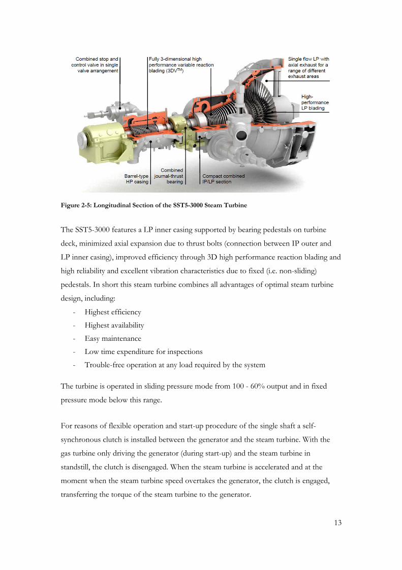
Figure 2-5: Longitudinal Section of the SST5-3000 Steam Turbine
The SST5-3000 features a LP inner casing supported by bearing pedestals on turbine
deck, minimized axial expansion due to thrust bolts (connection between IP outer and
LP inner casing), improved efficiency through 3D high performance reaction blading and
high reliability and excellent vibration characteristics due to fixed (i.e. non-sliding)
pedestals. In short this steam turbine combines all advantages of optimal steam turbine
design, including:
- Highest efficiency
- Highest availability
- Easy maintenance
- Low time expenditure for inspections
- Trouble-free operation at any load required by the system
The turbine is operated in sliding pressure mode from 100 - 60% output and in fixed
pressure mode below this range.
For reasons of flexible operation and start-up procedure of the single shaft a self-
synchronous clutch is installed between the generator and the steam turbine. With the
gas turbine only driving the generator (during start-up) and the steam turbine in
standstill, the clutch is disengaged. When the steam turbine is accelerated and at the
moment when the steam turbine speed overtakes the generator, the clutch is engaged,
transferring the torque of the steam turbine to the generator.

14
The condenser is a box type surface condenser. The condenser is installed lateral to the
LP turbine and forms an integral part of it. The steam dome, shell, hot well, and the
water boxes are steel fabrications. The condenser is fixed to the foundation beneath.
Thermal expansion will be accommodated by means of Teflon pads. The single flow LP
turbine outer casing is connected to the condenser via the steam dome. The steam dome
is welded to the exhaust casing of the turbine with the result that the LP turbine cylinder
and the condenser form one unit.
The water-steam cycle consists of the following systems:
- Condensate System including Condensate Supply, Condensate Preheating, Condensate Polishing
- Feed water System
- Heat Recovery Steam Generator
- Main Steam System (HP-, IP,-, LP-Main Steam) and Reheating System
The heat recovery steam generator (HRSG) is located downstream of the gas turbine
diffuser. The HRSG recovers GT-exhaust heat by generating steam which is used in the
water/steam-cycle to power the steam turbine. The steam generator produces steam in
three pressure stages: a high-pressure-, an intermediate-pressure- and a low-pressure
stage. All three stages are natural circulation with drum-type. A condensate pre-heater is
integrated in the HRSG. This arrangement enables high efficiency of the combined cycle
power plant by using the exhaust gas energy to preheat the condensate before it passes
towards the feed water pump and into the LP system.
The boiler casing is made of steel plate as required for the prevailing exhaust gas
temperatures. The HRSG is of the “cold casing” design with inside insulation. The gas
flow through the HRSG is horizontal. The HRSG is equipped with an outlet duct and
steel stack at the end. The stack is equipped with a damper and a silencer.
The heating surfaces consist of finned tubes which are suspended from a support
structure from the top. Each steam stage consists of an economizer (HP and IP),
evaporator and superheater. The feed water is heated in the economizer and fed into the
drum from where it flows into the evaporator, where a portion is evaporated. The thus
created water steam mixture flows back to the drum where it is separated. The saturated
15
steam is fed to the superheater where it is superheated up to main steam outlet
temperature.
The turbine exhaust steam is condensed by the sea water cooled condenser. The
condensate accumulated in the condenser hot well is discharged by one of the 2x100%
condensate extraction pumps (CEP) to the condensate preheating system. One
condensate extraction pump operates during full load operation and a stand by pump is
ready to cut in automatically in case of failure of the operating pump. The deaeration of
the condensate is mainly performed in the condenser under vacuum.
The condensate extraction pump delivers the condensate from the condenser hot well to
the LP drum and to the suction side of the feed water pumps via the condensate pre-
heater (CPH) of the HRSG.
A connection from the demineralized water distribution system is installed for filling of
the pump discharge side and pressurizing the condensate system during standstill.
Downstream a line for the injection cooling of the intermediate pressure (IP) and low
pressure (LP) bypass stations branches off.
The feed water is routed downstream of the HRSG condensate pre-heater in separate
suction lines to the feed water pumps via a strainer located upstream of each pump. An
automatic recirculation check valve for the pump minimum flow requirement is located
downstream of each feed water pump. The minimum flow is returned to the condensate
preheating system upstream of the condensate pre-heater. The HP pump discharge lines
are connected to a common header, which delivers feed water to the HP part of the
HRSG, IP feed water is tapped from an intermediate pump stage. The tapping lines are
connected to a common header, which delivers the feed water to the IP part of the
HRSG. Another tapping point of the feed water pump is used to recirculate feed water
via a common header to the condensate preheating system.
In order to achieve short start-up times and to control turbine trips a turbine bypass
system is provided. The bypass system consists of the HP-bypass connected to the cold
reheat as well as the IP- and LP- bypass, both dumped to the condenser, and related
attemperation systems. The bypass control valves are equipped with hydraulic drives.
16
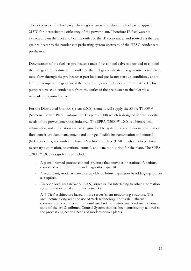
The objective of the fuel gas preheating system is to preheat the fuel gas to approx.
215°C for increasing the efficiency of the power plant. Therefore IP feed water is
extracted from the inlet and/ or the outlet of the IP economizer and routed via the fuel
gas pre-heater to the condensate preheating system upstream of the HRSG condensate
pre-heater.
Downstream of the fuel gas pre-heater a mass flow control valve is provided to control
the fuel gas temperature at the outlet of the fuel gas pre-heater. To guarantee a sufficient
mass flow through the pre-heater at part load and pre-heater start-up conditions, and to
limit the temperature gradient at the pre-heater, a recirculation pump is installed. This
pump returns cold condensate from the outlet of the pre-heater to the inlet via a
recirculation control valve.
For the Distributed Control System (DCS) Siemens will supply the SPPA-T3000™
(Siemens Power Plant Automation Teleperm 3000) which is designed for the specific
needs of the power generation industry. The SPPA-T3000™ DCS is a hierarchical
information and automation system (Figure 1). The system uses continuous information
flow, consistent data management and storage, flexible instrumentation and control
(I&C) concepts, and uniform Human Machine Interface (HMI) platforms to perform
necessary automation, operational control, and data monitoring for the plant. The SPPA-
T3000™ DCS design features include:
- A plant-oriented process control structure that provides operational functions, combined with monitoring and diagnostic capability
- A redundant, modular structure capable of future expansion by adding equipment as required
- An open local area network (LAN) structure for interfacing to other automation systems and external computer networks
- A ‘3-Tier’ architecture based on the server/client networking structure. This architecture along with the use of Web technology, Industrial Ethernet communications and a component-based software structure combine to form a state-of-the-art Distributed Control System that has been consistently tailored to the process engineering needs of modern power plants.
17
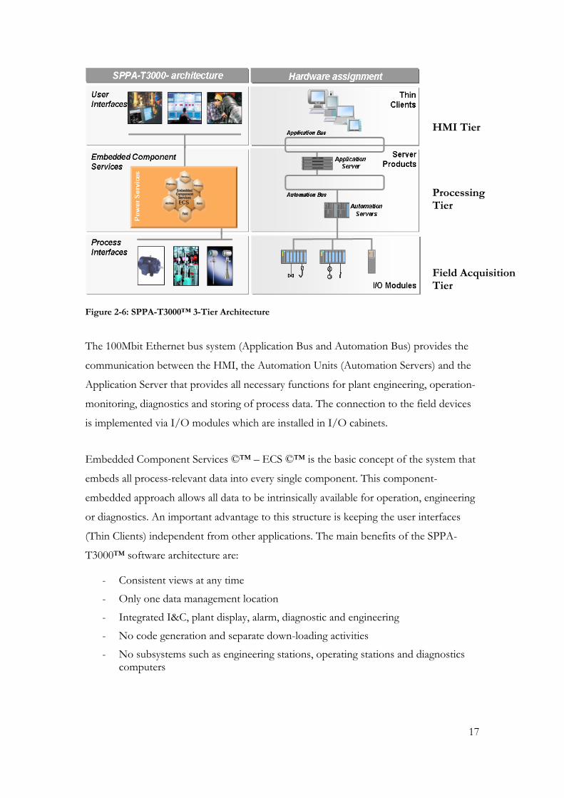
Figure 2-6: SPPA-T3000™ 3-Tier Architecture
The 100Mbit Ethernet bus system (Application Bus and Automation Bus) provides the
communication between the HMI, the Automation Units (Automation Servers) and the
Application Server that provides all necessary functions for plant engineering, operation-
monitoring, diagnostics and storing of process data. The connection to the field devices
is implemented via I/O modules which are installed in I/O cabinets.
Embedded Component Services ©™ – ECS ©™ is the basic concept of the system that
embeds all process-relevant data into every single component. This component-
embedded approach allows all data to be intrinsically available for operation, engineering
or diagnostics. An important advantage to this structure is keeping the user interfaces
(Thin Clients) independent from other applications. The main benefits of the SPPA-
T3000™ software architecture are:
- Consistent views at any time
- Only one data management location
- Integrated I&C, plant display, alarm, diagnostic and engineering
- No code generation and separate down-loading activities
- No subsystems such as engineering stations, operating stations and diagnostics computers
HMI Tier
Processing Tier
Field Acquisition Tier
18
SPPA-T3000™ provides a range of services to achieve power plant functionality. All
functions are provided in a modular and independent manner. A single-user interface
called Workbench provides the central interaction point that allows the operator,
engineer, technician and manager to access all information, operate the plant, and
perform required configuration and engineering tasks and trouble-shooting tasks. All
views are displayed in windows, and several windows can be placed on the workbench.
2.3. Water Integration
For the Tuaspring facility a combined water system has been chosen, which serves the
power plant and the desalination unit. Water will be drawn from the sea and firstly routed
to the power plant where it is used as cooling water to condense the steam in the
condenser and to cool auxiliary services. As a result, the temperature of the cooling
water, which is then fed directly into the desalination plant, rises. Because the seawater is
going through the RO system at a higher temperature, the RO pumps will not have to
work as hard, thereby saving a significant amount of energy.
2.4. Layout
The design for buildings and foundations complies with Siemens’ standard building
concept, which is applied for all its single-shaft units, and also complies with applicable
statutory requirements, as well as with the Tuaspring specific conditions.
Based on the results of the soil investigation and test piling, the foundation slabs are
made out of reinforced concrete. The building superstructure is skeleton steel structure
with metal cladding. In order to remove heat generated by the components, the buildings
are equipped with a ventilation system.

19
Figure 2-7: The Combined Cycle Power Plant within the Tuaspring Facility
The turbine building is a compact structural steel building of rectangular design and
contains gas turbine, generator and steam turbine with their associated components (e.g.
evacuation pumps, condensate cleaning system, main condensate pumps, closed cooling
water pumps and the heat exchangers for the closed cooling water system). The main
machine components are arranged in a single train in the following order: gas turbine,
generator, clutch, steam turbine and the condenser arranged transversally to the turbine
axis. The air intake filter house is located next to the annex at the side of the main bay of
the turbine building. The filtered air is led straight into the gas turbine compressor by
way of an aerodynamically optimized oblique steel fabricated duct, in which a silencer is
installed.
The air intake filter house is located next to the annex at the side of the main bay of the
turbine building. The filtered air is led straight into the gas turbine compressor by way of
an aerodynamically optimized oblique steel fabricated duct, in which a silencer is
installed.
Material access is provided via steel leaf folding doors or roller shutter door to the
entrance bay beside the turbine generator set. Access for inspection and maintenance to
all main and auxiliary equipment is fully ensured.
20
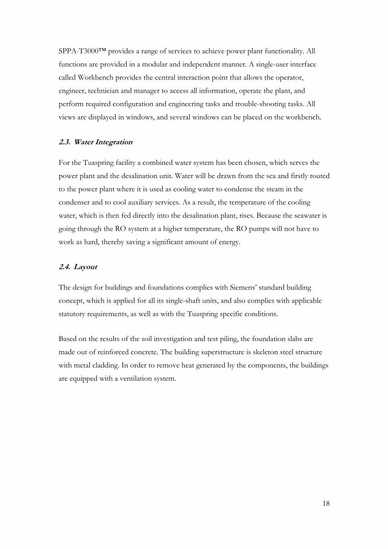
Figure 2-8: Power Island
Special care is taken to ensure the provision of short paths, dismantling and lay down
areas for overhaul operations and good accessibility to buildings and components for
maintenance.
The piped fuel gas is delivered from the site boundary terminal point through gas
filtering, metering and preheating equipment, to the gas turbine fuel gas skid. This
equipment is pre-assembled on skids. The back-up fuel oil (Diesel No 2) is delivered by
truck to site and stored in a day tank.
The prefabricated containers for electrical and I&C equipment are located outdoors close
to the turbine building to ensure short connections. The main transformer is arranged
laterally at the turbine building across the street for integration into the electrical system
of the Tuaspring facility. The 230 kV HV cables will be laid in a cable trench.

21
Figure 2-9: The Tuaspring CCPP
The above figure depicts a CCPP arrangement that follows the Siemens Reference Power
Plant design. The inherent flexibility of this design allows for an optimized arrangement
of auxiliary systems, facilitating short and practical routes for integration between the
CCPP and the desalination plant.
2.5. Electrical Integration
The power plant generator is connected via the generator circuit breaker to the step-up
transformer, which transforms the voltage from 20 kV to the grid voltage of 230 kV.
The desalination plant is connected to the 66 kV grid via transformers, which reduce the
voltage to 22 kV.
To integrate the plants, in addition to the usual auxiliary power transformer which taps
off the insulated phase bus duct (IPB) at the power plant and provides power to the 6.6
kV middle voltage system, 1 additional transformer is connected to the IPB, which
transforms the 20 kV generator voltage to the 22 kV necessary for the desalination plant.
The IPB is routed across a road to the transformer and switchgear structure. By this
connection, the whole desalination plant can be supplied with electricity generated by the
power plant directly.

22
Figure 2-10: Single Line
The 230kV power plant and 66kV desalination plant shall not be operated in parallel,
hence an open-transfer is selected.
A further connection between the power plant and the desalination plant is provided on
the 6.6kV busbar. This connection provides power for the seawater pumps, enabling the
power plant to operate standalone in case the 66kV power source to the desalination
plant is out of operation.
The overall declared fault current contributions to the grid connection point is one of the
key concerns of the power system. Extensive calculations and studies were performed as
required in the Singapore Transmission Code.
In order to achieve the required fault current limit, a rather high impedance for the
generator transformer was selected. Additional grounding options also help to address
these power system concerns.

23
3. Flexibility
Combined-cycle power plants (CCPPs) with their excellent dynamic behavior make it
possible to provide highly flexible solutions with the ability to balance out pronounced
daily load ramps. This is especially important in Asia where - unlike Europe's
interconnected power grid, within which all the various national power grids work
together - most Asian networks have none or only minor backup links to other networks.
Consequently, blackouts usually have to be avoided and grids need to be stabilized by
their own spare capacity. This fact is reflected in Asian grid codes, many of which impose
requirements similar to that of the UK grid code. The stringent demands of the UK grid
code likewise result from Great Britain's insular geography, which has always kept the
country from being fully tied into Europe's interconnected grid.
Figure 3-1: Intra-day power demand in Singapore (May 2010)
The figure above illustrates the kind of demand fluctuations with which the region must
contend. Singapore, for example, is confronted with daily load fluctuations of up to 60%.
Hence, the Singapore grid must maintain power capacities ranging between 4000 MW
and 6500 MW. CCPPs, with their relatively short reaction times, are definitely superior to
other kinds of power plant when it comes to satisfying peak loads. Moreover, they can
24
be systematically demand-optimized by way of today's on-demand start-stop cycling
modes. Moreover, new operational concepts now enable optimization of part-load
efficiency, so the units are able to minimize their fuel consumption under part-load
conditions.
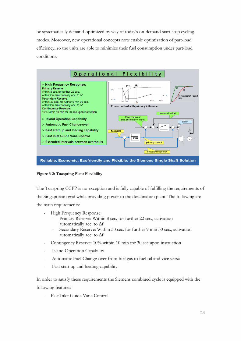
Figure 3-2: Tuaspring Plant Flexibility
The Tuaspring CCPP is no exception and is fully capable of fulfilling the requirements of
the Singaporean grid while providing power to the desalination plant. The following are
the main requirements:
- High Frequency Response: - Primary Reserve: Within 8 sec. for further 22 sec., activation
automatically acc. to Δf - Secondary Reserve: Within 30 sec. for further 9 min 30 sec., activation
automatically acc. to Δf
- Contingency Reserve: 10% within 10 min for 30 sec upon instruction
- Island Operation Capability
- Automatic Fuel Change-over from fuel gas to fuel oil and vice versa
- Fast start up and loading capability
In order to satisfy these requirements the Siemens combined cycle is equipped with the
following features:
- Fast Inlet Guide Vane Control
25
- A variable self-shifting synchronous clutch allows GT operation and start-up independent from ST operation
- Full Duty Bypass stations (100% steam flow including injection water) provide an easy matching of the steam conditions to ST requirements and de-coupling of the HRSG (load rejection) from the ST
- Short and simplified start-up procedure and operation of the units
- A higher environmental acceptability, since less steam is dumped to atmosphere due to shorter start-up procedure
- Operation of HRSG and ST without thermal stressing due to nearly constant steam temperatures in the GT load range above approx. 40% results in prolonged life time. This is achieved by variable inlet guide vanes (IGV) which keep the exhaust gas temperature constant at higher GT loads
- Load changes at GT loads above 40% with constant exhaust gas and steam temperatures are possible during sliding pressure operation with approximately 3 %/min based on typical HRSG loading transients. Above 60% ST load, control valves are completely open and the ST follows according to the change in steam production, without regulation of its output
- Below 60% ST load, control valves are throttled to keep steam pressure constant at the preset minimum pressure required by the HRSG
Primary and Secondary Frequency Control as required by the Singapore Transmission
Code is achieved by the increase or decrease of the gas turbine output in fuel gas mode.
Primary and Secondary Reserve is not additive, but consecutive. The droop setting is
adjustable at the GT speed controller. Typical droop setting values are in the range from
3 % to 8 %. Regulation Reserve and Contingency Reserve is provided by load set point
adjustment, provided that the plant is operated in part load accordingly.
Under islanded conditions (system disconnected from grid while the power plant is still
supplying external consumers), the plant will respond with its current frequency response
capability. Island operation is provided by the GT only – the ST is tripped.
The continuous operational frequency range of the unit is 47.5 Hz to 52 Hz according
the Singapore Transmission Code. The frequency range from 47 to 47.5 Hz is limited to
20 sec per event. Cumulated operation time in this frequency range is limited to 30 min
in total. After 30 min an inspection is recommended. Below 47 Hz and above 52 Hz
plant disconnection is initiated without time delay. The maximum (base load) output of
the gas turbine decreases at lower frequencies, depending on the ambient temperature.
26
The Singaporean regulations furthermore require that the power plant is capable of
switching safely from fuel gas to fuel oil and vice versa. Dedicated control systems and
the design of the burners allow the plant to changeover fuels during operation, without
disconnecting the plant from the grid.

27
4. Project Execution
4.1. Project Management
The scope and complexity of engineering, procuring, constructing, erecting and
commissioning a power plant requires the unrestricted and open co-operation of many
specialists with diverse training and knowledge but with one common goal: the
installation and commissioning of the plant to the satisfaction of all stakeholders.
In this particular project, it is not only a question of client and supplier. The integration
of the power plant into the desalination facility constitutes a special challenge for project
management.
Hyflux has vast experience in the execution of desalination projects as one of the major
global players in this market and Siemens is known as one of the world’s most reputable
power plant EPC companies. In order to leverage the individual capabilities of both
partners to a maximum, a tailored scope split has been developed. For example, the
complete civil works and the majority of the power plant’s balance of plant, including but
not limited to the demineralization plant, which is another Hyflux in-house product, have
been allocated to Hyflux’ scope as significant synergies are provided by the bundled
execution of desalination and power plant.
This scope split represents the technical basis of such a co-operation. Hence it needs to
be elaborated in great detail, considering all aspects of plant construction. Whereas
hardware interfaces can be easily defined, software and engineering interfaces are
challenging to synchronize. However, they play a crucial role in project execution and
therefore special attention has been paid to them. These interfaces involve engineering
tools, engineering standards, engineering sequences, documentation and communication
tools, nomenclature and abbreviations only to name a few.
Experts on both sides need to be capable of understanding the technical specifics of the
other party’s business and need to be flexible enough to modify designs, which may be
proven standalone, but, which, however, are not optimum for the common operation of
the whole plant.

28
It is quite obvious that such a complex and comprehensive interaction needs a different
way of co-operation. The traditional customer – supplier role-model is not suitable to
achieve the ultimate goal. A common, target-oriented mindset is required to make sure
that the diverse challenges can be overcome. It is one of the key tasks of the senior
project management that the attitude of the whole team, as well as the whole
organization, is developed and maintained as a partnership attitude. This sets the
foundation for an integrated project execution as one team.
The strategy to fulfill the tasks of the project management comprises the following key
elements:
- The empowerment of a general project manager with full authority and having the direct support of the top management
- Careful selection of highly qualified project managers and experienced personnel having the flexibility and mindset required
- Commitment to total quality management to consistently deliver a high quality product
- Commitment to rigorous health & safety and environmental management
- The use of effective standardised management procedures that integrate all parties
- The use of effective planning, project management and execution tools developed on the basis of the experience of executed projects
- Thorough and detailed planning, measurement and controlling of activities and of all involved parties
- Team building activities and rewards for good performance
- Siemens project management and liaison office in Singapore for permanent availability
- Frequent team meetings on a regular basis
Personnel of the project management organisations are appointed at an early stage, even
in the bidding and negotiation phase, in order to facilitate a flawless start into the project.
4.2. Project Control
After the effective date of the contract, a kick-off meeting between Hyflux and Siemens
project management was held to discuss and establish planning principles for the
proposed project control process.
29
Within 8 weeks of the effective date of the contract an Integrated Project Schedule (IPS),
which is based on the agreements reached in the executed contract, was established by
both parties.
The Integrated Project Schedule (IPS) contains detailed engineering, site mobilisation,
procurement, manufacturing, shipping, construction and commissioning activities
performed by the parties and their sub-suppliers.
A detailed identification of interfaces with respect to the chronological synchronization is
absolutely mandatory. During joint execution, full transparency and consistent tracking
of activities and milestones are among the core pillars of successful implementation.
Regular internal reviews will be performed to control performance in the engineering
departments as well as on site.
A progress reporting system is implemented based on an agreed standard format. Bar-
charts for both partners are prepared on a summary level. Critical activities are
highlighted.
4.3. Environment, Health and Safety
Special attention is paid by both Hyflux and Siemens to Environment, Health and Safety
(EHS). For Siemens, this attention is underlined by the full commitment of the entire
Siemens management hierarchy and is laid out in the Siemens-wide project management
system for all parties involved. Through this commitment and the stringent
implementation of all measures, the loss time frequency rate (LTFA) of all Siemens
projects worldwide is at a record low level of 0.08, which represents a further important
selection criterion.
30
5. Conclusion
This paper describes how Hyflux and Siemens are joining forces to construct the largest
Integrated Water and Power Plant (IWPP) in South East Asia, thereby making an
important contribution to Singapore’s long-term water and energy sustainability. The
Tuaspring project is a good example of the kind of sustainable infrastructure Asian cities
will need to implement in order to maintain quality of life, ensure competitiveness and
conserve natural resources and the environment.
Hyflux went through very detailed studies of various turbines by different companies,
and has chosen Siemens because of its ability to bring value to Hyflux’s investment in the
project.
Siemens contributes to the success of this project with high-technology turbine products
and sophisticated project management execution and partnering expertise. For the
Tuaspring project, Siemens understands the local rules and regulations and brings in a
high-value product to Singapore. The SGT5-4000F turbines deliver for this IWPP
project highest efficiency combined with utmost reliability.
In the future, Hyflux hopes to provide innovative solutions such as the Tuaspring IWPP
for similar projects around the region. Hyflux also wants to take this know-how to
develop projects overseas, and looks forward to working closely with Siemens on
upcoming projects.

31
6. References
[1] http://www.pub.gov.sg/water/Pages/default.aspx, September 2012
[2] A. Fattah, T. Hagedorn, “Highly flexible and reliable CCPPs to meet future market
demand in Asia”, PowerGen Asia, Singapore, October 2010
[3] A. Pickard, G. Meinecke, “Improved Combined Cycle Operational Flexibility Saves
Fuel”, PowerGen Asia, Kuala Lumpur, September 2011
[4] L. Balling, Dr. U. Tomschi, A. Pickard, G. Meinecke, “Fast Cycling and Grid Support
Capability of Combined Cycle Power Plants to optimize the Integration of
Renewable Generation into the European Grid: Live examples from projects in NL,
F, UK, D”, PowerGen Europe, Amsterdam, June. 2010

32
7. Copyright
The content of this paper is copyrighted by Siemens AG Energy Sector and Hyflux Ltd
and is licensed only to PennWell for publication and distribution. Any inquiries regarding
permission to use the content of this paper, in whole or in part, for any purpose must be
addressed to Siemens AG Energy Sector and Hyflux Ltd directly.
8. Disclaimer
This document contains forward-looking statements and information – that is,
statements related to future, not past, events. These statements may be identified either
orally or in writing by words as “expects”, “anticipates”, “intends”, “plans”, “believes”,
“seeks”, “estimates”, “will” or words of similar meaning. Such statements are based on
our current expectations and certain assumptions, and are, therefore, subject to certain
risks and uncertainties. A variety of factors, many of which are beyond Siemens’ and/or
Hyflux’s control, affect its operations, performance, business strategy and results and
could cause the actual results, performance or achievements of Siemens and/or Hyflux
worldwide to be materially different from any future results, performance or
achievements that may be expressed or implied by such forward-looking statements. For
us, particular uncertainties arise, among others, from changes in general economic and
business conditions, changes in currency exchange rates and interest rates, introduction
of competing products or technologies by other companies, lack of acceptance of new
products or services by customers targeted by Siemens and/or Hyflux worldwide,
changes in business strategy and various other factors. More detailed information about
certain of these factors is contained in Siemens’ filings with the SEC, which are available
on the Siemens website, www.siemens.com and on the SEC’s website, www.sec.gov.
Should one or more of these risks or uncertainties materialize, or should underlying
assumptions prove incorrect, actual results may vary materially from those described in
the relevant forward-looking statement as anticipated, believed, estimated, expected,
intended, planned or projected. Siemens and Hyflux do not intend or assume any
obligation to update or revise these forward-looking statements in light of developments
which differ from those anticipated. Trademarks mentioned in this document are the
property of Siemens AG and Hyflux Ltd, their affiliates or their respective owners.