Embed Size (px)
Citation preview

1
Arc Flash Calculations and Detailed Arc Flash Warning Labels
TSEWG TP-15 May 2012

i
Executive Summary NFPA 70E-2012 requires a detailed arc flash warning label that specifies either the available incident energy in cal/cm2 or the required level of personal protective equipment (PPE) that must be worn at a particular work location. This white paper explains why detailed arc flash warning labels are likely inappropriate for most military installations. In support of this position, this white paper discusses the following: An overview of arc flash calculations and their technical requirements.
The role of electrical system maintenance and testing in determining an arc flash result.
The evolution of arc flash criteria, including changes to the criteria with each industry
standard update.
The impact of the above considerations on the content of an arc flash warning label.
Note: It is not the intent of this paper to discourage the development of arc flash calculations. Instead, the intent is to assure that arc flash calculations are rigorous and address all requirements. Arc Flash Calculations Simply stated, an arc flash result, expressed in either incident energy in cal/cm2 or the required level of personal protective equipment (PPE), assumes that an upstream overcurrent protective device sensed, responded to, and ultimately cleared the arcing fault within its published time-current curve. The arc flash calculation result is based on several factors: The available short circuit current at the intended work location.
The calculated arcing fault current associated with the available short circuit current.
The equipment configuration at the work location.
The intended working distance from the assumed arcing location.
Identification of the upstream overcurrent protective device that is credited for clearing the
short circuit.
Evaluation of the upstream overcurrent protective device’s time-current response to the calculated arcing current.
Confirmation that the upstream overcurrent protective device is capable of performing its safety function of clearing the fault based on past maintenance and testing, as applicable.

ii
Analysis Requirements Before a Detailed Arc Flash Label Can Be Developed A detailed arc flash label depends on the results of an arc flash calculation. The following is required to complete an arc flash calculation: Develop a one-line of the system to be analyzed. An up-to-date one-line drawing is an
NFPA 70E requirement.
Develop a software analysis model for the system to be evaluated. The model has to produce accurate short circuit and coordination analyses before an arc flash study can start. Verify that the equipment of interest is properly rated for the available short circuit current. Note: a software package designed for this analysis, such as EasyPower or SKM’s modules, is necessary except for only the simplest of evaluations.
Determine the arc flash analysis method to be used (NFPA 70E provides different acceptable methods that can produce different results) and document the basis for the selected method.
Determine the arc flash criteria to be applied to the study. This includes 1) establishing the working distance, 2) determining if the main breaker will be credited for work on a panelboard, switchboard, or switchgear that contains that breaker, and 3) defining any limitations of the study.
As part of the calculation, address maintenance and testing for the protective devices credited for arc flash protection. The engineer is certifying that circuit breakers credited for protection by the study are expected to be functional and operate within the manufacturer’s published time-current curves. Otherwise, these protective devices must be excluded from the study.
Necessary Actions Before the Information on a Detailed Arc Flash Label Can Be Used After a detailed arc flash label has been applied, several conditions might change that affect the validity of the information listed on the label. Confirm the following before relying on a detailed arc flash label: Complete an Energized Electrical Work Permit that defines the intended work procedure and
safety practices.
Compare the activities intended as stated on the Energized Electrical Work Permit to the arc flash label to confirm that the arc flash label applies to these activities.
Verify that the information stated on the arc flash label is still valid. This includes the settings of the upstream protective device credited in the arc flash study for providing arc flash protection. Have there been other system changes that might affect the information on the label?

iii
Verify that the condition of maintenance of the upstream protective device is acceptable. Has maintenance and testing validated that the upstream protective device can work as designed?
Determine if the industry standards (and date) that formed the basis for the arc flash calculation are still the most current. Note: arc flash requirements have changed with each issuance of NFPA 70E and the next issuance of IEEE 1584 is expected to modify the calculation method. A change in the industry standards can invalidate the information provided on an arc flash label.
If the label is more than 5 years old, it should not be relied upon for arc flash guidance. Summary of Reasons Why the Unified Facilities Criteria Specify Only a General Arc Flash Label UFC 3-501-01, Electrical Engineering, and UFC 3-560-01, Electrical Safety, O&M, specify only a general label as shown below.
WARNING!
Figure UFC 3-560-01 Arc Flash Warning Label The concern of the tri-service electrical working group is that a detailed arc flash warning label, fully compliant with NFPA 70E at the time is was installed, can yield incorrect and unsafe results. The reasons for only endorsing a general label include: Arc flash analysis methods are still evolving. Each issuance of NFPA 70E between 2004 to
2012 has changed the criteria. The next issuance of IEEE 1584 is expected to modify the equations that form the basis for the calculation. These industry standard changes can invalidate the information on a detailed label. When industry standards are revised, it is important that the label reflect current safety standards and analysis methods. Electrical safety is not something that can be grandfathered to an older standard.

iv
A detailed arc flash warning label will not recognize or acknowledge system configuration changes that affect the analysis results. For example, changing a circuit breaker trip setting can change the arc flash results from Category 0 to Category 4 or higher.
Confirmation of periodic maintenance and testing is a crucial input to an arc flash evaluation. With the commissioning process for new equipment properly completed, routine and periodic maintenance and testing is still required to continue the validation of the detailed arc flash warning label. A detailed arc flash warning label that was produced for a properly maintained system will be invalid in the future if routine and periodic maintenance and testing are not continually performed.
A detailed arc flash warning label does not describe the assumed working conditions and system configuration that formed the basis for the calculated arc flash levels. For example, detailed arc flash labels usually do not specify the breaker settings for the upstream protective device assumed to provide arc flash protection, whether or not the main breaker at the panel was assumed to provide protection, or future maintenance/testing requirements to maintain the integrity of the label.
v
Table of Contents
1 Introduction – Arc Flash Calculation Overview.......................................................................1
1.1 What Does an Arc Flash Calculation Result Mean? .........................................................1
1.2 Example Arc Flash Calculation for Low Voltage Circuit Breakers ..................................2
1.3 Calculation Variability Depending on Analysis Method ..................................................5
1.4 Periodic Maintenance and Testing as an Input to an Arc Flash Analysis .........................6
1.5 NFPA 70E Criteria if an Arc Flash Calculation Is Not Performed .................................11 1.5.1 NFPA 70E-2009.......................................................................................................11 1.5.2 NFPA 70E-2012.......................................................................................................12
2 Arc Flash Warning Labels ......................................................................................................13
2.1 NFPA 70E Requirement for Arc Flash Warning Labels .................................................13
2.2 Unified Facility Criteria Requirement for Arc Flash Warning Labels ............................13 2.2.1 Energized Work Practices and Verification of Arc Flash Study Assumptions .......14 2.2.2 Periodic Maintenance and Testing ...........................................................................15 2.2.3 Continuing Criteria Changes....................................................................................15
2.3 Detailed Label That Addresses All Issues .......................................................................16
2.4 Arc Flash Label For a System That Has Not Had Maintenance or Testing ....................17
3 References ..............................................................................................................................18

1
1 Introduction – Arc Flash Calculation Overview
NFPA 70E-2012 requires a detailed arc flash warning label that specifies either the available incident energy in cal/cm2 or the required level of personal protective equipment (PPE) that must be worn at a particular work location. This white paper explains why detailed arc flash warning labels are likely inappropriate for most military installations. In support of this position, this white paper discusses the following: An overview of arc flash calculations and their technical requirements.
The role of electrical system maintenance and testing in determining an arc flash result.
The evolution of arc flash criteria, including changes to the criteria with each industry
standard update.
The impact of the above considerations on the content of an arc flash warning label.
1.1 What Does an Arc Flash Calculation Result Mean?
Simply stated, an arc flash result, expressed in either incident energy in cal/cm2 or the required level of personal protective equipment (PPE), assumes that an upstream overcurrent protective device sensed, responded to, and ultimately cleared the arcing fault within its published time-current curve. Unless analysis limitations or disclaimers are specifically stated, an engineer signing an arc flash calculation is effectively certifying that the overcurrent protective device credited for providing arc flash protection will function as intended. The arc flash calculation result is based on several factors: The available short circuit current at the intended work location.
The calculated arcing fault current associated with the available short circuit current.
The equipment configuration at the work location.
The intended working distance from the assumed arcing location.
Identification of the upstream overcurrent protective device that is credited for clearing the
short circuit.
Evaluation of the upstream overcurrent protective device’s time-current response to the calculated arcing current.
Confirmation that the upstream overcurrent protective device is capable of performing its safety function of clearing the fault based on past maintenance and testing, as applicable.

2
1.2 Example Arc Flash Calculation for Low Voltage Circuit Breakers
NFPA 70E does not specify a single analysis method for an arc flash calculation, but it does describe various methods in its Annex D, Incident Energy and Flash Protection Boundary Calculation Methods. Arc flash calculations are typically based on one or both of two methods: NFPA 70E-2009, Annex D, sections D.5 and D.6.
IEEE 1584-2002, Guide for Performing Arc Flash Calculations. As an example, Figure 1 shows a simple electrical system with a distribution transformer supplying a simplified service entrance panel. The symmetrical short circuit current is about 29 kA at Bus 4, which represents the service entrance panel. As shown, the arc flash results at Bus 4 are Category 0, with an arc flash boundary of 10.7 inches.
BUS-1
BUS-4
UTILITY6 kA12 (X/R)6 kA15 (X/R)
TX-1500 kVA12.47 - 0.208 kV4%
BUS-1 6.005
BUS-4 29.493
UTILITY
TX-1
29.1
70
5.92
3 6.
000
0.00
5 0.
005
31.6
26
0.32
3
0.32
3
BUS-1
BUS-4
#0 @ 18"0.7 cal / cm² @ 18"10.7" AFB
UTILITY
TX-1
Electrical Model Short Circuit Calculation Arc Flash Calculation Figure 1 Simple Electrical System Model The arc flash result shown in Figure 1 is based on the main circuit breaker providing the electrical overcurrent protection. In this example, the main breaker is a GE TKM molded case

3
circuit breaker (MCCB), rated for 1,200 amperes continuous current. The Category 0 arc flash result is based on an instantaneous trip of this circuit breaker; the trip setting is set to LOW (3,600 amperes) for this example. The bolted fault current is about 29 kA and the calculated arcing fault current is about 8 kA, which is above the instantaneous trip setting. Figure 2 shows this configuration.
.5
.5
.6
.6
.8
.8
1
1
2
2
3
3
4
4
5
5
6
6
7
7
8
8
9
9
10
10
2
2
3
3
4
4
5
5
6
6
7
7
8
8
9
9
100
100
2
2
3
3
4
4
5
5
6
6
7
7
8
8
9
9
1000
1000
2
2
3
3
4
4
5
5
6
6
7
7
8
8
9
9
10000
10000
.01 .01
.02 .02
.03 .03
.04 .04
.05 .05
.07 .07
.1 .1
.2 .2
.3 .3
.4 .4
.5 .5
.7 .7
1 1
2 2
3 3
4 45 5
7 7
10 10
20 20
30 30
40 4050 50
70 70
100 100
200 200
300 300
400 400500 500
700 700
1000 1000
CURRENT IN AMPERES X 100 AT 208 VOLTS
CURRENT IN AMPERES X 100 AT 208 VOLTS
TIM
E I
N S
EC
ON
DS
TIM
E I
N S
EC
ON
DS
MCCB 1GE K1200TKM12Frame = 1200A (1200AT)Trip = 1200Inst = LO (3600A)
MCCB 135430A
MCCB 1100% Arcing Current8659A
BUS-4
#0 @ 18"0.7 cal / cm² @ 18"10.7" AFB
Figure 2 MCCB – Instantaneous Trip at Minimum Figure 3 shows what happens if the instantaneous trip is raised from LOW (3,600 amperes) to HIGH (10,000) amperes. The result of this single action is that the arc flash calculation result is

4
now much higher than Category 4 and is identified as Extreme Danger. The reason for this dramatic change is because the MCCB is now providing a time delay trip rather than an instantaneous trip for the calculated level of arcing current. In this case, the upstream distribution transformer fuses are the recognized fault clearing device with a time delay of almost 8 seconds as shown in Figure 4.
.5
.5
.6
.6
.8
.8
1
1
2
2
3
3
4
4
5
5
6
6
7
7
8
8
9
9
10
10
2
2
3
3
4
4
5
5
6
6
7
7
8
8
9
9
100
100
2
2
3
3
4
4
5
5
6
6
7
7
8
8
9
9
1000
1000
2
2
3
3
4
4
5
5
6
6
7
7
8
8
9
9
10000
10000
.01 .01
.02 .02
.03 .03
.04 .04
.05 .05
.07 .07
.1 .1
.2 .2
.3 .3
.4 .4
.5 .5
.7 .7
1 1
2 2
3 3
4 45 5
7 7
10 10
20 20
30 30
40 4050 50
70 70
100 100
200 200
300 300
400 400500 500
700 700
1000 1000
CURRENT IN AMPERES X 100 AT 208 VOLTS
CURRENT IN AMPERES X 100 AT 208 VOLTS
TIM
E IN
SE
CO
ND
S
TIM
E IN
SE
CO
ND
S
MCCB 1GE K1200TKM12Frame = 1200A (1200AT)Trip = 1200Inst = HI (10000A)
MCCB 135430A
MCCB 185% Arcing Current7360A
BUS-4
Extreme Danger @ 18"176.4 cal / cm² @ 18"532.8" AFB
Figure 3 MCCB – Instantaneous Trip at Maximum

5
.5
.5
.6
.6
.8
.8
1
1
2
2
3
3
4
4
5
5
6
6
7
7
8
8
9
9
10
10
2
2
3
3
4
4
5
5
6
6
7
7
8
8
9
9
100
100
2
2
3
3
4
4
5
5
6
6
7
7
8
8
9
9
1000
1000
2
2
3
3
4
4
5
5
6
6
7
7
8
8
9
9
10000
10000
.01 .01
.02 .02
.03 .03
.04 .04
.05 .05
.07 .07
.1 .1
.2 .2
.3 .3
.4 .4
.5 .5
.7 .7
1 1
2 2
3 3
4 45 5
7 7
10 10
20 20
30 30
40 4050 50
70 70
100 100
200 200
300 300
400 400500 500
700 700
1000 1000
CURRENT IN AMPERES X 100 AT 208 VOLTS
CURRENT IN AMPERES X 100 AT 208 VOLTS
TIM
E I
N S
EC
ON
DS
TIM
E I
N S
EC
ON
DS
MCCB 1GE K1200TKM12Frame = 1200A (1200AT)Trip = 1200Inst = HI (10000A)
MCCB 135430A
TX-1CooperCurrent-LimitELX25
BUS-4
Extreme Danger @ 18"176.4 cal / cm² @ 18"532.8" AFB
Figure 4 MCCB With Instantaneous Trip at Maximum and Upstream Transformer Fusing
1.3 Calculation Variability Depending on Analysis Method
Another arc flash calculation feature to consider is that different analysis methods produce different results. Figure 5 provides an example for this simple system. The IEEE 1584 method is shown on the left and the NFPA 70E Annex D.5 method is shown on the right. Refer to the NFPA 70E Handbook or Reference 9 for additional information regarding the differences between the two methods. In general, the IEEE 1584 method is considered better in that it has more test data behind it, but a conservative approach could be to take the worst case result of

6
both methods. The difference between the two calculation methods is more pronounced at medium voltage.
BUS-1
BUS-4
#0 @ 18"0.7 cal / cm² @ 18"10.7" AFB
UTILITY
TX-1
BUS-1
BUS-4
#1 @ 18"1.4 cal / cm² @ 18"17.3" AFB
UTILITY
TX-1
Figure 5 Example of IEEE 1584 Versus NFPA 70E Calculation The IEEE 1584 Working Group is currently performing additional testing, which will likely create an improved technical basis for the empirical equations that they develop or validate (but they will also likely change the equations, which will result in different calculation results also).
1.4 Periodic Maintenance and Testing as an Input to an Arc Flash Analysis In 2009, the American Society of Civil Engineers graded America’s national infrastructure a ‘D’, the lowest grade ever. Aviation infrastructure was graded ‘D’, dams were a ‘D’, and waste water system were a ‘D-’. With respect to electrical systems, the point here is that, similar to other infrastructure systems, very little maintenance and testing of electrical systems is actually performed, with many low voltage electrical systems never receiving any periodic maintenance or testing. This is the dirty laundry of arc flash calculations – an arc flash calculation based on the actuation of a protective device that has never been maintained or tested verges on

7
engineering negligence1. Electrical personnel have been injured by arcing events when the arc flash prediction was Category 0 because the upstream circuit breakers failed to trip throughout the arcing event. A poorly maintained electrical system is a hazard to anyone who works on it or near it. The following summarizes the requirements with respect to maintenance and testing: The 2012 edition of NFPA 70E states, “The arc flash hazard analysis shall take into
consideration the design of the overcurrent protective device, including its condition of maintenance.” The NFPA 70E-2012 Handbook refers to Section 21.10 of NFPA 70B-2006 for maintenance of protective devices; this section specifies overcurrent time-current testing of the protective devices.”
The Fine Print Note for NFPA 70E Article 200 states, “Refer to NFPA 70B, Recommended Practice for Electrical Equipment Maintenance, and ANSI/NETA MTS-2007, Standard for Maintenance Testing Specifications for Electrical Power Distribution Equipment and Systems, for guidance on maintenance frequency, methods, and tests.”
NFPA 70E Article 205.3, General Maintenance Requirements, states, “Electrical equipment shall be maintained in accordance with manufacturer’s instructions or industry consensus standards to reduce the risk of failure and the subsequent exposure of employees to electrical hazards.”
NFPA 70E Article 205.4, Overcurrent Protective Devices, states, “Overcurrent protective devices shall be maintained in accordance with the manufacturers’ instructions or industry consensus standards. Maintenance, tests, and inspections shall be documented.”
Several industry studies have noted high failure rates of low voltage circuit breakers after only a few years of service. One recent industry survey determined that 23 percent of the circuit breakers tested had an issue affecting the protective device operation. And, over 10 percent of the devices did not function at all when tested. Facility studies performed at the low voltage level must determine if historic maintenance practices have been adequate to rely on circuit breakers as upstream protective devices with respect to electrical safety. It would be inappropriate for an engineer to assume that old MCCBs that have never been maintained in accordance with NETA MTS or NFPA 70B will trip per their overcurrent time-current curves. And, such a critical assumption would likely not be included as a disclaimer on the equipment arc flash warning label. To summarize: The calculated arc flash incident energy depends on how long it takes an upstream protective
device to sense, respond to, and eventually clear the arcing fault. If the upstream protective
1 Wikipedia: Negligence is a type of tort or delict (also known as a civil wrong). “Negligence” is not the same as “carelessness”, because someone might be exercising as much care as they are capable of, yet still fall below the level of competence expected of them. It is the opposite of “diligence”. It can be generally defined as conduct that is culpable because it falls short of what a reasonable person would do to protect another individual from foreseeable risks of harm.

8
device is a set of fuses, they likely can respond as intended. If the upstream protective device is a circuit breaker that has not been checked or maintained for the last 30 years, there is no assurance whatsoever that it will respond in accordance with its published time-current curve.
Even if the trip device is functional, can the circuit breaker actually open? Has it ever been
operated? For medium voltage and low voltage power circuit breakers, has the lubricant hardened or have any required moving parts broken? Once again, it is hard to envision taking credit for an arc flash study on a system that has received little or no periodic maintenance.
Even properly maintained equipment sometimes breaks or fails to operate when needed. If
this happens, an arcing fault would be cleared by a different upstream protective device, likely with a longer time delay. If the energized work is performed at the service entrance panel, the next upstream device is usually upstream of the distribution transformer and will take anywhere from several seconds to hundreds of seconds to respond to a secondary-side overcurrent event.
Before starting or contracting for an arc flash study for an existing facility at the low voltage level, determine whether the electrical equipment maintenance inside the facility has been acceptable. If maintenance has never been performed on the switchboards and panelboards inside the facility, then there is no assurance that the protective devices (circuit breakers) will actually respond in accordance with their published time-current curves or that the circuit breakers are capable of opening properly. It’s one thing to push a button on an electrical analysis software package and get an arc flash number. It’s an entirely different thing to confirm that the circuit breaker really is capable of responding in accordance with the arc flash analysis results. The following figures show examples of equipment that cannot be relied on to respond in accordance with their published time-current curves.
Figure 6 Low Voltage Power Circuit Breaker – 1959 Vintage Last Inspected in 1993

9
Figure 7 Old Panelboard MCCBs – Never Inspected or Tested
Figure 8 Outdoor Service Entrance Equipment – 25-Year Old Circuit Breakers in a Hot Environment

10
Figure 9 Severely Rusted Panelboard – 30 Years Old
Figure 10 Deteriorated Enclosure New facilities might be different with respect to maintenance as an issue. The commissioning process can confirm that everything initially works properly, provided the commissioning process actually does time-current testing on low voltage circuit breakers in accordance with NETA ATS or NFPA 70B. The arc flash evaluation for a new system should determine if the commissioning process did perform and document testing of the installed overcurrent protective devices.

11
1.5 NFPA 70E Criteria if an Arc Flash Calculation Is Not Performed NFPA 70E-2009 has been superseded by NFPA 70E-2012. The 2009 edition allowed certain exemptions and exceptions, which have been modified or removed in the 2012 edition. Despite this elimination, the 2009 criteria are still discussed here because the fine print associated with some of the criteria are important to understand.
1.5.1 NFPA 70E-2009 For voltage levels between 50 volts and 600 volts, NFPA 70E-2009 provides a default arc flash protection boundary of 4 ft; however, this boundary includes specific technical criteria that must be confirmed before it can be used. Article 130.3(A)(1) states:
In those cases where detailed arc flash hazard analysis calculations are not performed for systems that are between 50 volts and 600 volts, the Arc Flash Protection Boundary shall be 4.0 ft, based on the product of clearing time of 2 cycles (0.033 sec) and the available bolted fault current of 50 kA or any combination not exceeding 100 kA cycles (1667 ampere seconds). When the product of clearing times and bolted fault current exceeds 100 kA cycles, the Arc Flash Protection Boundary shall be calculated.
The NFPA 70E-2009 Handbook clarifies the above criteria by adding:
It is important to note that some information about the installation must be known to use the default Arc Flash Protection Boundary. For instance, the worker must know both the clearing time of the overcurrent device and the available fault current. These values vary by location in the facility power system. They need to be known for each location in the facility where work will be performed when PPE is being chosen.
For a circuit breaker, a clearing time of 2 cycles represents an instantaneous trip. For virtually all circuit breakers, a trip in the time delay region will take anywhere from several seconds to a few hundred seconds (refer to Figures 2 and 3). If the available short circuit current is 10 kA rather than 50 kA, then a clearing time of 10 cycles would be allowed, which is still well below a circuit breaker time delay trip region. If the available short circuit current is only 1 kA rather than 50 kA, then a clearing time of 100 cycles would be allowed, which is also still well below most circuit breakers’ time delay trip region. The above criteria effectively assume that the circuit breaker operates within its instantaneous trip region. To summarize, an electrical worker can use the default working distance of 4 ft if the following is confirmed: The available bolted fault short circuit current is known for the intended work location.
The overcurrent protective device that will clear the fault is identified.
The overcurrent protective device is expected to be able to clear a fault in accordance with
the time limits stated above.

12
For a circuit breaker, the past maintenance and testing is considered adequate to ensure that the circuit breaker will clear the fault in accordance with its published time-current curves.
It is probably fair to say that most electrical workers probably do not know the available short circuit current throughout their system; have little or no training in interpreting circuit breaker time-current curves; and have little or no training in assessing the adequacy of maintenance and testing to assure the overcurrent protective device is capable of performing its function in accordance with its published time-current curves. Notice that the above criteria define a default arc flash protection boundary, but the required level of PPE when working within this boundary is not addressed. Table 130.7(C)(9) of NFPA 70E defines the Hazard/Risk Category for various tasks; however, this table is also based on an expectation of a maximum available bolted fault current and a maximum allowed clearing time. The table provides the following notes that are referenced inside the table: 1. Maximum of 25 kA short circuit current available; maximum of 0.03 sec (2 cycle) fault
clearing time.
2. Maximum of 65 kA short circuit current available; maximum of 0.03 sec (2 cycle) fault clearing time.
3. Maximum of 42 kA short circuit current available; maximum of 0.33 sec (20 cycle) fault clearing time.
4. Maximum of 35 kA short circuit current available; maximum of up to 0.5 sec (30 cycle) fault clearing time.
Once again, the Hazard/Risk Category levels provided for specific tasks in NFPA 70E have technical bases that must be considered before allowing their use.
1.5.2 NFPA 70E-2012 NFPA 70E eliminated the article that allowed a default 4-foot arc flash boundary. Companies that provided arc flash training based on this default value will need to revise their training program. The fine print regarding maximum short circuit current and maximum circuit breaker clearing time has been moved into the body of the tables. Before the tables can be used, the electrical worker still has to know : The available bolted fault short circuit current for the intended work location.
The overcurrent protective device that will clear the fault and that it is expected to be able to
clear a fault in accordance with the time limits stated in the tables.
For a circuit breaker, the past maintenance and testing confirmation to ensure that the circuit breaker will clear the fault in accordance with its published time-current curves.

13
2 Arc Flash Warning Labels
2.1 NFPA 70E Requirement for Arc Flash Warning Labels NFPA 70E-2009 Paragraph 130.3.C. requires:
Equipment Labeling. Equipment shall be field marked with a label containing the available incident energy or required level of PPE.
NFPA 70E-2012 Paragraph 130.5.C. completely changed this section and requires:
Electrical equipment such as switchboards, panelboards, industrial control panels, meter socket enclosures, and motor control centers that are in other than dwelling units, and are likely to require examination, adjustment, servicing, or maintenance while energized, shall be field marked with a label containing all the following information: (1) At least one of the following:
a. Available incident energy and the corresponding working distance b. Minimum arc rating of clothing c. Required level of PPE d. Highest Hazard/Risk Category (HRC) for the equipment
(2) Nominal system voltage (3) Arc flash boundary Exception: Labels applied prior to September 30, 2011, are acceptable if they contain the available incident energy or required level of PPE. The method of calculating and data to support the information for the label shall be documented.
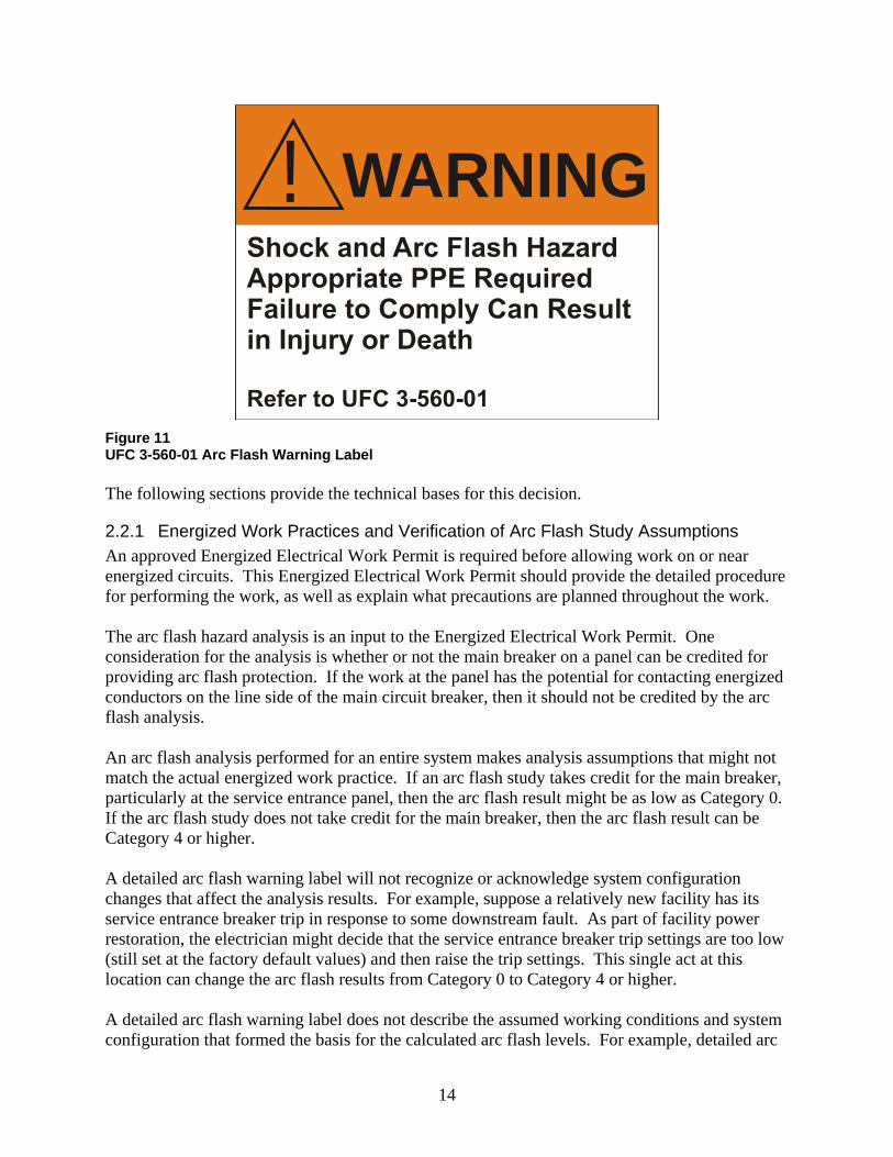
2.2 Unified Facility Criteria Requirement for Arc Flash Warning Labels As part of the development of UFC 3-501-01, Electrical Engineering, and 3-560-01, Electrical Safety, O&M, the Tri-Service Electrical Working Group (TSEWG) has deliberately specified general arc flash warning labels rather than the detailed arc flash warning labels required by NFPA 70E-2012. Figure 11 shows an example of the required label for the Army, Air Force, and Navy.
14
WARNING!
Figure 11 UFC 3-560-01 Arc Flash Warning Label The following sections provide the technical bases for this decision.
2.2.1 Energized Work Practices and Verification of Arc Flash Study Assumptions An approved Energized Electrical Work Permit is required before allowing work on or near energized circuits. This Energized Electrical Work Permit should provide the detailed procedure for performing the work, as well as explain what precautions are planned throughout the work. The arc flash hazard analysis is an input to the Energized Electrical Work Permit. One consideration for the analysis is whether or not the main breaker on a panel can be credited for providing arc flash protection. If the work at the panel has the potential for contacting energized conductors on the line side of the main circuit breaker, then it should not be credited by the arc flash analysis. An arc flash analysis performed for an entire system makes analysis assumptions that might not match the actual energized work practice. If an arc flash study takes credit for the main breaker, particularly at the service entrance panel, then the arc flash result might be as low as Category 0. If the arc flash study does not take credit for the main breaker, then the arc flash result can be Category 4 or higher. A detailed arc flash warning label will not recognize or acknowledge system configuration changes that affect the analysis results. For example, suppose a relatively new facility has its service entrance breaker trip in response to some downstream fault. As part of facility power restoration, the electrician might decide that the service entrance breaker trip settings are too low (still set at the factory default values) and then raise the trip settings. This single act at this location can change the arc flash results from Category 0 to Category 4 or higher. A detailed arc flash warning label does not describe the assumed working conditions and system configuration that formed the basis for the calculated arc flash levels. For example, detailed arc

15
flash labels usually do not specify the breaker settings for the upstream protective device assumed to provide arc flash protection, whether or not the main breaker at the panel was assumed to provide protection, or future maintenance/testing requirements to maintain the integrity of the label. Personnel should not rely on the label for their PPE requirements. Instead, an Energized Electrical Work Permit should establish the PPE levels based on the intended work approach and system configuration.
2.2.2 Periodic Maintenance and Testing Confirmation of periodic maintenance and testing is a crucial input to an arc flash evaluation. Even if the commissioning process for the equipment was properly completed, maintenance and testing is still required in the future. A detailed arc flash warning label that was produced for a properly maintained system can still be inappropriate in the future if maintenance and testing are never again performed.
2.2.3 Continuing Criteria Changes Arc flash analysis and protection methods are a developing science and art. The analysis methods defined by NFPA 70E and IEEE 1584 are expected to be modified over the next several years, which also might result in different calculated arc flash boundary values. Several industry papers have identified shortcomings with the test arrangements upon which the IEEE 1584 empirically-developed equations are based. The IEEE 1584 Working Group is conducting additional testing in support of the analysis methods. If the analysis methods change, the analysis results will likely change. This means that very detailed labels will no longer match the new analysis results – relabeling will be necessary. As an example of the extent to which the criteria can change, consider the default arc flash protection boundary of 4 ft for voltage levels between 50 volts and 600 volts: NFPA 70E-2004: … for systems that are 600 volts or less, the Flash Protection Boundary
shall be 4.0 ft, based on the product of clearing time of 6 cycles (0.1 sec) and the available bolted fault current of 50 kA or any combination not exceeding 300 kA cycles (5000 ampere seconds).
NFPA 70E-2009: … for systems that are between 50 volts and 600 volts, the Arc Flash Protection Boundary shall be 4.0 ft, based on the product of clearing time of 2 cycles (0.033 sec) and the available bolted fault current of 50 kA or any combination not exceeding 100 kA cycles (1667 ampere seconds).
NFPA 70E-2012: Eliminated the 4.0 ft boundary.
Notice that NFPA 70E-2009 significantly modified the technical bases for the 4 ft default arc flash protection boundary. Similarly, NFPA 70E-2009 modified some of the Table 130.7(C)(9) technical bases regarding available short circuit current or assumed fault clearing times. Then, NFPA 70E-2012 completely changed it again; NFPA 70E-2012 makes extensive revisions to the 70E 2009 criteria, further illustrating the point that this is very much an evolving area.

16
The lesson learned here is that each new revision of NFPA 70E or IEEE 1584 will require an evaluation of the impact of any changes. Unlike the grandfathering of existing electrical systems when the National Electrical Code is revised, the criteria of NFPA 70E can affect existing electrical safety programs with each revision.
2.3 Detailed Label That Addresses All Issues
The point of this white paper is that a detailed arc flash warning label, fully compliant with NFPA 70E at the time is was installed, can yield incorrect and unsafe results. It is not enough to simply state some required PPE level for a work location. If a detailed label is used, it must address the following: Assumptions made in the arc flash study regarding the intended energized work practices.
The example arc flash warning label provided below illustrates the need to distinguish whether or not credit can be taken for the main breaker. This is only one of several decisions that might be necessary as part of an Energized Electrical Work Permit.
Future revisions to NFPA 70E and IEEE 1584. As these documents are revised, it is
important that the label reflect current safety standards and analysis methods. Electrical safety is not something that can be grandfathered to an older standard.
Adequate maintenance and testing. It would be negligent to apply a detailed label to an
equipment that has not been maintained or tested in accordance with industry standards. If the equipment has been maintained, what is the expiration date for a detailed label once it is applied? At some point in the future, maintenance and testing is necessary; otherwise, the label should be removed.
The following provides an example of a detailed label that addresses the above considerations.

17
WARNING!
Figure 12 Detailed Arc Flash Warning Label Assume that all of the above items are satisfied in support of a detailed label. NFPA 70E, Article 130.3, also requires the “arc flash analysis shall be updated when a major modification or renovation takes place. It shall be reviewed periodically, not to exceed five years, to account for changes in the electrical distribution system that could affect the results of the arc flash hazard analysis.” Each military base is a small city; this will be difficult to accomplish for all electrical systems operating at 50 volts and above.
2.4 Arc Flash Label For a System That Has Not Had Maintenance or Testing
The general label authorized by the tri-services and shown in Figure 11 does not address systems that have had inadequate maintenance and testing to support an arc flash calculation. For these systems, a label requiring equipment shutdown before allowing any work could be used. Figure 13 shows one example.

18
WARNING!
Figure 13 Arc Flash Warning Label if Maintenance and Testing Is Not Performed
3 References
1. NFPA 70B-2006 and -2010, Recommended Practice for Electrical Equipment Maintenance.
2. NFPA 70E-2012, Standard for Electrical Safety in the Workplace.
3. NFPA 70E-2009, Standard for Electrical Safety in the Workplace
4. NFPA 70E-2004, Standard for Electrical Safety in the Workplace
5. NETA ATS-2009, Acceptance Testing Specifications for Electrical Power Distribution Equipment and Systems.
6. NETA MTS-2007, Maintenance Testing Specifications for Electrical Power Distribution Equipment and Systems.
7. IEEE-1584-2002™, IEEE Guide for Performing Arc-Flash Hazard Calculations.
8. UFC 3-501-01, Electrical Engineering.
9. UFC 3-560-01, Electrical Safety, O&M.
10. John Lane, PE; Arc-Flash Hazard Analysis – “Putting the Pieces of the Puzzle Together”.

19
11. Ron Widup and Jim White; Labels: What Happens with the New NFPA 70E?, NetaWorld Spring 2009.
12. Thomas McCauley; NFPA 70E: A Comparison of Recent Editions, EC&M, August 2010.
13. Michael Callanan, Dennis Neitzel, and Dan Neeser; Preventative Maintenance and Reliability of Low Voltage Overcurrent Protective Devices, http://www.cooperbussmann.com/pdf/2352ccf4-8fe2-4062-98e3-e6336b695f5d.pdf.
14. Jim White; NFPA 70E and NFPA 70B: Sisters in Safety, NEC Digest, June 2007.
15. R. Wilkins, M. Allison, and M. Lang; Effect of Electrode Orientation in Arc Flash Testing, 2005 Industry Applications Conference, October 2005.
16. R. Wilkins, M. Allison, and M. Lang; Effect of Insulating Barriers in Arc Flash Testing, 53rd Annual Technical Conference of the IEEE PCIC, September 2006.
17. Kerry Heid; Survey Says! Maintenance is Critical as Part of Your Electrical Safety Program, NetaWorld Summer 2011.
Note: The EasyPower 9.0 Power System Software was used to prepare this white paper.