Embed Size (px)
Citation preview
ETSI TS 125 214 V7.4.0 (2007-03)
Technical Specification
Universal Mobile Telecommunications System (UMTS);Physical layer procedures (FDD)
(3GPP TS 25.214 version 7.4.0 Release 7)
ETSI
ETSI TS 125 214 V7.4.0 (2007-03) 1 3GPP TS 25.214 version 7.4.0 Release 7
Reference RTS/TSGR-0125214v740
Keywords UMTS
ETSI
650 Route des Lucioles F-06921 Sophia Antipolis Cedex - FRANCE
Tel.: +33 4 92 94 42 00 Fax: +33 4 93 65 47 16
Siret N° 348 623 562 00017 - NAF 742 C
Association à but non lucratif enregistrée à la Sous-Préfecture de Grasse (06) N° 7803/88
Important notice
Individual copies of the present document can be downloaded from: http://www.etsi.org
The present document may be made available in more than one electronic version or in print. In any case of existing or perceived difference in contents between such versions, the reference version is the Portable Document Format (PDF).
In case of dispute, the reference shall be the printing on ETSI printers of the PDF version kept on a specific network drive within ETSI Secretariat.
Users of the present document should be aware that the document may be subject to revision or change of status. Information on the current status of this and other ETSI documents is available at
http://portal.etsi.org/tb/status/status.asp
If you find errors in the present document, please send your comment to one of the following services: http://portal.etsi.org/chaircor/ETSI_support.asp
Copyright Notification
No part may be reproduced except as authorized by written permission. The copyright and the foregoing restriction extend to reproduction in all media.
© European Telecommunications Standards Institute 2007.
All rights reserved.
DECTTM, PLUGTESTSTM and UMTSTM are Trade Marks of ETSI registered for the benefit of its Members. TIPHONTM and the TIPHON logo are Trade Marks currently being registered by ETSI for the benefit of its Members. 3GPPTM is a Trade Mark of ETSI registered for the benefit of its Members and of the 3GPP Organizational Partners.
ETSI
ETSI TS 125 214 V7.4.0 (2007-03) 2 3GPP TS 25.214 version 7.4.0 Release 7
Intellectual Property Rights IPRs essential or potentially essential to the present document may have been declared to ETSI. The information pertaining to these essential IPRs, if any, is publicly available for ETSI members and non-members, and can be found in ETSI SR 000 314: "Intellectual Property Rights (IPRs); Essential, or potentially Essential, IPRs notified to ETSI in respect of ETSI standards", which is available from the ETSI Secretariat. Latest updates are available on the ETSI Web server (http://webapp.etsi.org/IPR/home.asp).
Pursuant to the ETSI IPR Policy, no investigation, including IPR searches, has been carried out by ETSI. No guarantee can be given as to the existence of other IPRs not referenced in ETSI SR 000 314 (or the updates on the ETSI Web server) which are, or may be, or may become, essential to the present document.
Foreword This Technical Specification (TS) has been produced by ETSI 3rd Generation Partnership Project (3GPP).
The present document may refer to technical specifications or reports using their 3GPP identities, UMTS identities or GSM identities. These should be interpreted as being references to the corresponding ETSI deliverables.
The cross reference between GSM, UMTS, 3GPP and ETSI identities can be found under http://webapp.etsi.org/key/queryform.asp.
ETSI
ETSI TS 125 214 V7.4.0 (2007-03) 3 3GPP TS 25.214 version 7.4.0 Release 7
Contents
Intellectual Property Rights ................................................................................................................................2
Foreword.............................................................................................................................................................2
Foreword.............................................................................................................................................................6
1 Scope ........................................................................................................................................................7
2 References ................................................................................................................................................7
3 Definitions and Abbreviations..................................................................................................................7 3.1 Definitions..........................................................................................................................................................7 3.2 Abbreviations .....................................................................................................................................................7
4 Synchronisation procedures .....................................................................................................................8 4.1 Cell search ..........................................................................................................................................................8 4.2 Common physical channel synchronisation .......................................................................................................8 4.2.1 P-CCPCH radio frame timing.......................................................................................................................9 4.2.2 S-CCPCH soft combining timing .................................................................................................................9 4.3 DPCCH/DPDCH/F-DPCH synchronisation.......................................................................................................9 4.3.1 Synchronisation primitives ...........................................................................................................................9 4.3.1.1 General ....................................................................................................................................................9 4.3.1.2 Downlink synchronisation primitives .....................................................................................................9 4.3.1.3 Uplink synchronisation primitives ........................................................................................................10 4.3.2 Radio link establishment and physical layer reconfiguration for dedicated channels.................................10 4.3.2.1 General ..................................................................................................................................................10 4.3.2.2 Node B radio link set state machine......................................................................................................11 4.3.2.3 Synchronisation procedure A................................................................................................................11 4.3.2.4 Synchronisation procedure B ................................................................................................................12 4.3.3 Radio link monitoring.................................................................................................................................13 4.3.3.1 Downlink radio link failure ...................................................................................................................13 4.3.3.2 Uplink radio link failure/restore............................................................................................................13 4.3.4 Transmission timing adjustments ...............................................................................................................13
5 Power control .........................................................................................................................................14 5.1 Uplink power control........................................................................................................................................14 5.1.1 PRACH.......................................................................................................................................................14 5.1.1.1 General ..................................................................................................................................................14 5.1.1.2 Setting of PRACH control and data part power difference ...................................................................14 5.1.2 DPCCH/DPDCH ........................................................................................................................................14 5.1.2.1 General ..................................................................................................................................................14 5.1.2.2 Ordinary transmit power control ...........................................................................................................15 5.1.2.2.1 General ............................................................................................................................................15 5.1.2.2.2 Algorithm 1 for processing TPC commands ...................................................................................16 5.1.2.2.3 Algorithm 2 for processing TPC commands ...................................................................................17 5.1.2.3 Transmit power control in compressed mode .......................................................................................18 5.1.2.4 Transmit power control in the uplink DPCCH power control preamble...............................................20 5.1.2.5 Setting of the uplink DPCCH/DPDCH relative powers........................................................................21 5.1.2.5.1 General ............................................................................................................................................21 5.1.2.5.2 Signalled gain factors ......................................................................................................................21 5.1.2.5.3 Computed gain factors.....................................................................................................................21 5.1.2.5.4 Setting of the uplink DPCCH/DPDCH relative powers in compressed mode.................................22 5.1.2.5A Setting of the uplink HS-DPCCH power relative to DPCCH power ....................................................22 5.1.2.5B Setting of the uplink E-DPCCH and E-DPDCH powers relative to DPCCH power.............................23 5.1.2.5B.1 E-DPCCH/DPCCH..........................................................................................................................23 5.1.2.5B.2 E-DPDCH/DPCCH .........................................................................................................................24 5.1.2.5C Setting of the uplink DPCCH gain factor when no DPDCH is configured...........................................26 5.1.2.6 Maximum and minimum power limits ..................................................................................................26 5.1.3 Void ............................................................................................................................................................27 5.2 Downlink power control...................................................................................................................................27
ETSI
ETSI TS 125 214 V7.4.0 (2007-03) 4 3GPP TS 25.214 version 7.4.0 Release 7
5.2.1 DPCCH/DPDCH/F-DPCH .........................................................................................................................28 5.2.1.1 General ..................................................................................................................................................28 5.2.1.2 Ordinary transmit power control ...........................................................................................................28 5.2.1.2.1 UE behaviour...................................................................................................................................28 5.2.1.2.2 UTRAN behaviour ..........................................................................................................................28 5.2.1.3 Power control in compressed mode ......................................................................................................29 5.2.1.4 Void.......................................................................................................................................................31 5.2.2 Void ............................................................................................................................................................31 5.2.3 Void ............................................................................................................................................................31 5.2.4 AICH ..........................................................................................................................................................31 5.2.5 PICH ...........................................................................................................................................................31 5.2.6 S-CCPCH....................................................................................................................................................31 5.2.7 Void ............................................................................................................................................................31 5.2.8 Void ............................................................................................................................................................31 5.2.9 Void ............................................................................................................................................................31 5.2.10 HS-SCCH ...................................................................................................................................................31 5.2.11 HS-PDSCH.................................................................................................................................................31 5.2.12 E-AGCH .....................................................................................................................................................32 5.2.13 E-HICH.......................................................................................................................................................32 5.2.14 E-RGCH .....................................................................................................................................................32 5.2.15 MICH..........................................................................................................................................................32
6 Random access procedure ......................................................................................................................32 6.1 Physical random access procedure ...................................................................................................................32 6.1.1 RACH sub-channels ...................................................................................................................................33 6.1.2 RACH access slot sets ................................................................................................................................34 6.2 Void..................................................................................................................................................................34
6A HS-DSCH-related procedures ................................................................................................................34 6A.1 General procedure ............................................................................................................................................34 6A.1.1 UE procedure for receiving HS-DSCH and HS-SCCH ..............................................................................35 6A.1.2 UE procedure for reporting channel quality indication (CQI) and precoding control indication (PCI)......37 6A.1.2.1 CQI reporting procedure in case the UE is not configured in MIMO mode .........................................37 6A.1.2.2 Composite PCI/CQI reporting procedure in case the UE is configured in MIMO mode......................37 6A.1.3 Node B procedure for transmitting the HS-DSCH .....................................................................................38 6A.2 Channel quality indicator (CQI) definition.......................................................................................................39 6A.2.1 CQI definition when the UE is not configured in MIMO mode .................................................................39 6A.2.2 CQI definition when the UE is configured in MIMO mode .......................................................................39 6A.2.3 CQI tables ...................................................................................................................................................40 6A.3 Operation during compressed mode on the associated DPCH or F-DPCH......................................................49 6A.4 Precoding control indication (PCI) definition ..................................................................................................49
6B E-DCH related procedures .....................................................................................................................50 6B.1 ACK/NACK detection .....................................................................................................................................50 6B.2 Relative grants detection ..................................................................................................................................50 6B.3 E-DCH control timing ......................................................................................................................................50 6B.3.1 10 ms E-DCH TTI ......................................................................................................................................50 6B.3.2 2 ms E-DCH TTI ........................................................................................................................................51 6B.4 Operation during compressed mode .................................................................................................................51 6B.4.1 Uplink compressed mode............................................................................................................................51 6B.4.2 Downlink compressed mode.......................................................................................................................52
6C Discontinuous transmission and reception procedures...........................................................................52 6C.1 Uplink HS-DPCCH transmission .....................................................................................................................53 6C.2 Discontinuous uplink DPCCH transmission operation ....................................................................................53 6C.2.1 Uplink DPCCH transmission pattern..........................................................................................................53 6C.2.2 Uplink DPCCH preamble and postamble ...................................................................................................55 6C.3 Discontinuous downlink reception ...................................................................................................................55 6C.4 HS-SCCH orders ..............................................................................................................................................57 6C.5 Operation during compressed mode .................................................................................................................57
7 Closed loop mode 1 transmit diversity...................................................................................................58 7.1 General procedure ............................................................................................................................................59 7.2 Determination of feedback information ...........................................................................................................60
ETSI
ETSI TS 125 214 V7.4.0 (2007-03) 5 3GPP TS 25.214 version 7.4.0 Release 7
7.2.1 End of frame adjustment.............................................................................................................................60 7.2.2 Normal initialisation ...................................................................................................................................61 7.2.3 Operation during compressed mode ...........................................................................................................61 7.2.3.1 Downlink in compressed mode and uplink in normal mode .................................................................61 7.2.3.2 Both downlink and uplink in compressed mode ...................................................................................61 7.2.3.3 Uplink in compressed mode and downlink in normal mode .................................................................62 7.2.4 Initialisation during compressed mode .......................................................................................................62 7.2.4.1 Downlink in compressed mode .............................................................................................................62 7.2.4.2 Uplink in compressed mode..................................................................................................................63 7.3 Void..................................................................................................................................................................63
8 Idle periods for IPDL location method...................................................................................................63 8.1 General .............................................................................................................................................................63 8.2 Parameters of IPDL..........................................................................................................................................63 8.3 Calculation of idle period position ...................................................................................................................64
9 MIMO operation of HS-DSCH ..............................................................................................................66 9.1 General procedure ............................................................................................................................................67
Annex A (informative): (no title)...........................................................................................................68 A.1 Antenna verification .........................................................................................................................................68 A.2 Computation of feedback information for closed loop mode 1 transmit diversity ...........................................69
Annex B (Informative): Power control .................................................................................................70
B.1 Downlink power control timing .............................................................................................................70
B.2 Example of implementation in the UE ...................................................................................................71
B.3 UL power control when losing UL synchronisation ..............................................................................71
Annex C (Informative): Cell search procedure....................................................................................72
Annex D (informative): Change history ...............................................................................................73
History ..............................................................................................................................................................77
ETSI
ETSI TS 125 214 V7.4.0 (2007-03) 6 3GPP TS 25.214 version 7.4.0 Release 7
Foreword This Technical Specification (TS) has been produced by the 3rd Generation Partnership Project (3GPP).
The contents of the present document are subject to continuing work within the TSG and may change following formal TSG approval. Should the TSG modify the contents of this present document, it will be re-released by the TSG with an identifying change of release date and an increase in version number as follows:
Version x.y.z
where:
x the first digit:
1 presented to TSG for information;
2 presented to TSG for approval;
3 or greater indicates TSG approved document under change control.
y the second digit is incremented for all changes of substance, i.e. technical enhancements, corrections, updates, etc.
z the third digit is incremented when editorial only changes have been incorporated in the document.
ETSI
ETSI TS 125 214 V7.4.0 (2007-03) 7 3GPP TS 25.214 version 7.4.0 Release 7
1 Scope The present document specifies and establishes the characteristics of the physicals layer procedures in the FDD mode of UTRA.
2 References The following documents contain provisions which, through reference in this text, constitute provisions of the present document.
• References are either specific (identified by date of publication, edition number, version number, etc.) or non-specific.
• For a specific reference, subsequent revisions do not apply.
• For a non-specific reference, the latest version applies. In the case of a reference to a 3GPP document (including a GSM document), a non-specific reference implicitly refers to the latest version of that document in the same Release as the present document.
[1] 3GPP TS 25.211: "Physical channels and mapping of transport channels onto physical channels (FDD)".
[2] 3GPP TS 25.212: "Multiplexing and channel coding (FDD)".
[3] 3GPP TS 25.213: "Spreading and modulation (FDD)".
[4] 3GPP TS 25.215: "Physical layer – Measurements (FDD)".
[5] 3GPP TS 25.331: "RRC Protocol Specification".
[6] 3GPP TS 25.433: "UTRAN Iub Interface NBAP Signalling".
[7] 3GPP TS 25.101: "UE Radio transmission and Reception (FDD)".
[8] 3GPP TS 25.133: "Requirements for Support of Radio Resource Management (FDD)".
[9] 3GPP TS 25.321: "MAC protocol specification".
[10] 3GPP TS 25.306: "UE Radio Access Capabilities".
3 Definitions and Abbreviations
3.1 Definitions For the purposes of the present document, the following terms and definitions apply:
L1 combining period: An interval of contiguous TTIs when S-CCPCHs, each on different RLs, may be soft combined.
3.2 Abbreviations For the purposes of the present document, the following abbreviations apply:
ACK Acknowledgement AICH Acquisition Indicator Channel ASC Access Service Class BCH Broadcast Channel CCPCH Common Control Physical Channel
ETSI
ETSI TS 125 214 V7.4.0 (2007-03) 8 3GPP TS 25.214 version 7.4.0 Release 7
CCTrCH Coded Composite Transport Channel CPICH Common Pilot Channel CQI Channel Quality Indicator CRC Cyclic Redundancy Check DCH Dedicated Channel DL Downlink DPCCH Dedicated Physical Control Channel DPCH Dedicated Physical Channel DPDCH Dedicated Physical Data Channel DTX Discontinuous Transmission E-DCH Enhanced Dedicated Channel E-DPCCH E-DCH Dedicated Physical Control Channel E-DPDCH E-DCH Dedicated Physical Data Channel E-AGCH E-DCH Absolute Grant Channel E-HICH E-DCH HARQ Acknowledgement Indicator Channel E-RGCH E-DCH Relative Grant Channel F-DPCH Fractional Dedicated Physical Channel HSDPA High Speed Downlink Packet Access HS-DSCH High Speed Downlink Shared Channel HS-PDSCH High Speed Physical Downlink Shared Channel HS-SCCH High Speed Physical Downlink Shared Control Channel MICH MBMS Indicator Channel NACK Negative Acknowledgement P-CCPCH Primary Common Control Physical Channel PCA Power Control Algorithm PICH Paging Indicator Channel PRACH Physical Random Access Channel RACH Random Access Channel RL Radio Link RPL Recovery Period Length RSCP Received Signal Code Power S-CCPCH Secondary Common Control Physical Channel SCH Synchronisation Channel SFN System Frame Number SIR Signal-to-Interference Ratio SNIR Signal to Noise Interference Ratio TFC Transport Format Combination TPC Transmit Power Control TrCH Transport Channel TTI Transmission Time Interval UE User Equipment UL Uplink UTRAN UMTS Terrestrial Radio Access Network
4 Synchronisation procedures
4.1 Cell search During the cell search, the UE searches for a cell and determines the downlink scrambling code and common channel frame synchronisation of that cell. How cell search is typically done is described in Annex C.
4.2 Common physical channel synchronisation The radio frame timing of all common physical channels can be determined after cell search.
ETSI
ETSI TS 125 214 V7.4.0 (2007-03) 9 3GPP TS 25.214 version 7.4.0 Release 7
4.2.1 P-CCPCH radio frame timing
The P-CCPCH radio frame timing is found during cell search and the radio frame timing of all common physical channel are related to that timing as described in [1].
4.2.2 S-CCPCH soft combining timing
Higher layers will provide timing information when S-CCPCHs, each on different RLs,can be soft combined. The timing information allows the UE to determine the L1 combining period that applies to each S-CCPCH. The information also identifies the S-CCPCHs and the RLs that can be soft combined. The set of S-CCPCHs that can be combined does not change during an L1 combining period. When S-CCPCHs can be soft combined, all S-CCPCHs shall contain identical bits in their data fields, although the TFCI fields of the S-CCPCHs may be different. (TFC detection when S-CCPCHs may be soft combined is discussed in [2].) The maximum delay between S-CCPCHs that the UE may combine is set by UE performance requirements. The maximum number of S-CCPCHs that UE may simultaneously combine is defined by the UE capability in [10].
4.3 DPCCH/DPDCH/F-DPCH synchronisation
4.3.1 Synchronisation primitives
4.3.1.1 General
For the dedicated channels, synchronisation primitives are used to indicate the synchronisation status of radio links, both in uplink and downlink. The definition of the primitives is given in the following subclauses.
4.3.1.2 Downlink synchronisation primitives
If UL_DTX_mode=0 (see section 6C), layer 1 in the UE shall every radio frame check synchronisation status of either the DPCH or the F-DPCH depending on which is configured. If UL_DTX_mode=1 (see section 6C), the layer 1 in the UE shall check synchronisation status of the F-DPCH for each radio frame in which the F-DPCH transmission is known to be present in at least one slot, and for the other radio frames, the layer 1 will not indicate any synchronisation status to the higher layers. Synchronisation status is indicated to higher layers using the CPHY-Sync-IND and CPHY-Out-of-Sync-IND primitives.
The criteria for reporting synchronisation status are defined in two different phases.
The first phase starts when higher layers initiate physical dedicated channel establishment (as described in [5]) or whenever the UE initiates synchronisation procedure A (as described in section 4.3.2.1) and lasts until 160 ms after the downlink dedicated channel is considered established by higher layers (physical channel establishment is defined in [5]). During this time out-of-sync shall not be reported and in-sync shall be reported using the CPHY-Sync-IND primitive if the following criterion is fulfilled:
- The UE estimates the DPCCH quality or the quality of the TPC fields of the F-DPCH frame received from the serving HS-DSCH cell over the previous 40 ms period to be better than a threshold Qin. This criterion shall be assumed not to be fulfilled before 40 ms of DPCCH quality measurements have been collected. Qin is defined implicitly by the relevant tests in [7].
The second phase starts 160 ms after the downlink dedicated channel is considered established by higher layers. During this phase both out-of-sync and in-sync are reported as follows.
Out-of-sync shall be reported using the CPHY-Out-of-Sync-IND primitive if any of the following criteria is fulfilled:
- UL_DTX_mode=0 (see section 6C) and the UE estimates the DPCCH quality or the quality of the TPC fields of the F-DPCH frame received from the serving HS-DSCH cell over the previous 160 ms period to be worse than a threshold Qout. Qout is defined implicitly by the relevant tests in [7].
- UL_DTX_mode=1 (see section 6C) and the UE estimates the quality of the TPC fields of the F-DPCH from the serving HS-DSCH cell over the previous 240 slots in which the TPC symbols are known to be present to be worse than a threshold Qout. Qout is defined implicitly by the relevant tests in [7].
ETSI
ETSI TS 125 214 V7.4.0 (2007-03) 103GPP TS 25.214 version 7.4.0 Release 7
- The 20 most recently received transport blocks with a non-zero length CRC attached, as observed on all TrCHs using non-zero length CRC mapped to the DPDCH, have been received with incorrect CRC. In addition, over the previous 160 ms, all transport blocks with a non-zero length CRC attached have been received with incorrect CRC. In case no TFCI is used this criterion shall not be considered for the TrCH(s) not using guided detection if they do not use a non-zero length CRC in all transport formats. If no transport blocks with a non-zero length CRC attached are received over the previous 160 ms this criterion shall not be assumed to be fulfilled.
For a DPCH, in-sync shall be reported using the CPHY-Sync-IND primitive if both of the following criteria are fulfilled:
- The UE estimates the DPCCH quality over the previous 160 ms period to be better than a threshold Qin. Qin is defined implicitly by the relevant tests in [7].
- At least one transport block with a non-zero length CRC attached, as observed on all TrCHs using non-zero length CRC mapped to the DPDCH, is received in a TTI ending in the current frame with correct CRC. If no transport blocks are received, or no transport block has a non-zero length CRC attached in a TTI ending in the current frame and in addition over the previous 160 ms at least one transport block with a non-zero length CRC attached has been received with a correct CRC, this criterion shall be assumed to be fulfilled. If no transport blocks with a non-zero length CRC attached are received over the previous 160 ms this criterion shall also be assumed to be fulfilled. In case no TFCI is used this criterion shall not be considered for the TrCH(s) not using guided detection if they do not use a non-zero length CRC in all transport formats.
For a F-DPCH, in-sync shall be reported using the CPHY-Sync-IND primitive if any of the following criteria is fulfilled:
- UL_DTX_mode=0 (see section 6C) and the UE estimates the quality of the TPC fields of the F-DPCH frame received from the serving HS-DSCH cell over the previous 160 ms period to be better than a threshold Qin. Qin is defined implicitly by the relevant tests in [7].
- UL_DTX_mode=1 (see section 6C) and the UE estimates the quality of the TPC fields of the F-DPCH from the serving HS-DSCH cell over the previous 240 slots in which the TPC symbols are known to be present to be better than a threshold Qin. Qin is defined implicitly by the relevant tests in [7].
How the primitives are used by higher layers is described in [5]. The above definitions may lead to radio frames where neither the in-sync nor the out-of-sync primitives are reported.
4.3.1.3 Uplink synchronisation primitives
Layer 1 in the Node B shall every radio frame check synchronisation status of all radio link sets. Synchronisation status is indicated to the RL Failure/Restored triggering function using either the CPHY-Sync-IND or CPHY-Out-of-Sync-IND primitive. Hence, only one synchronisation status indication shall be given per radio link set.
The exact criteria for indicating in-sync/out-of-sync is not subject to specification, but could e.g. be based on received DPCCH quality or CRC checks. One example would be to have the same criteria as for the downlink synchronisation status primitives.
4.3.2 Radio link establishment and physical layer reconfiguration for dedicated channels
4.3.2.1 General
Two synchronisation procedures are defined in order to obtain physical layer synchronisation of dedicated channels between UE and UTRAN:
- Synchronisation procedure A : This procedure shall be used when at least one downlink dedicated physical channel (i.e. a DPCH or F-DPCH) and one uplink dedicated physical channel are to be set up on a frequency and none of the radio links after the establishment/reconfiguration existed prior to the establishment/reconfiguration which also includes the following cases :
- the UE was previously on another RAT i.e. inter-RAT handover
- the UE was previously on another frequency i.e. inter-frequency hard handover
ETSI
ETSI TS 125 214 V7.4.0 (2007-03) 113GPP TS 25.214 version 7.4.0 Release 7
- the UE has all its previous radio links removed and replaced by other radio links i.e. intra-frequency hard-handover
- after it fails to complete an inter-RAT, intra- or inter-frequency hard-handover [8], the UE attempts to re-establish [5] all the dedicated physical channels which were already established immediately before the hard-handover attempt. In this case only steps c) and d) of synchronisation procedure A are applicable.
- Synchronisation procedure B : This procedure shall be used when one or several radio links are added to the active set and at least one of the radio links prior to the establishment/reconfiguration still exists after the establishment/reconfiguration.
- If higher layers indicate that the UE shall not perform any synchronisation procedure for timing maintained intra- and inter-frequency hard handover, the UE shall not perform any of the synchronisation procedures A or B. If higher layers indicate to the Node B timing maintained intra- or inter-frequency hard handover where the UE does not perform any of the synchronisation procedures A or B, the Node B shall perform steps a) and b) of synchronisation procedure B.
For all physical layer reconfigurations not listed above, the UE and UTRAN shall not perform any of the synchronisation procedures listed above.
The two synchronisation procedures are described in subclauses 4.3.2.3 and 4.3.2.4 respectively.
4.3.2.2 Node B radio link set state machine
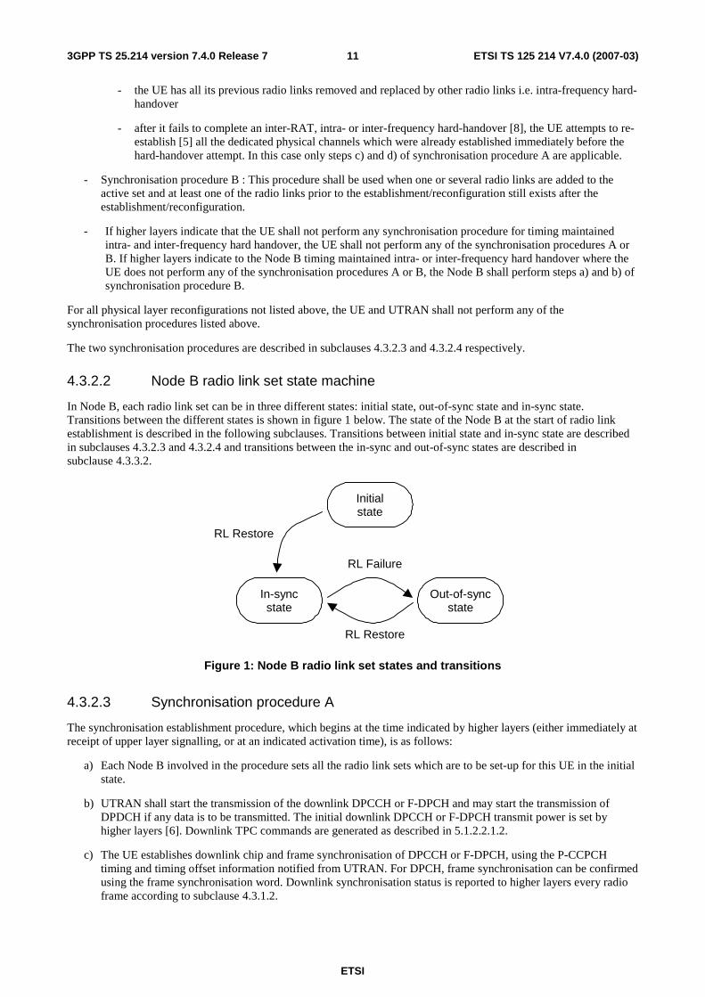
In Node B, each radio link set can be in three different states: initial state, out-of-sync state and in-sync state. Transitions between the different states is shown in figure 1 below. The state of the Node B at the start of radio link establishment is described in the following subclauses. Transitions between initial state and in-sync state are described in subclauses 4.3.2.3 and 4.3.2.4 and transitions between the in-sync and out-of-sync states are described in subclause 4.3.3.2.
Out-of-syncstate
In-syncstate
Initialstate
RL Restore
RL Restore
RL Failure
Figure 1: Node B radio link set states and transitions
4.3.2.3 Synchronisation procedure A
The synchronisation establishment procedure, which begins at the time indicated by higher layers (either immediately at receipt of upper layer signalling, or at an indicated activation time), is as follows:
a) Each Node B involved in the procedure sets all the radio link sets which are to be set-up for this UE in the initial state.
b) UTRAN shall start the transmission of the downlink DPCCH or F-DPCH and may start the transmission of DPDCH if any data is to be transmitted. The initial downlink DPCCH or F-DPCH transmit power is set by higher layers [6]. Downlink TPC commands are generated as described in 5.1.2.2.1.2.
c) The UE establishes downlink chip and frame synchronisation of DPCCH or F-DPCH, using the P-CCPCH timing and timing offset information notified from UTRAN. For DPCH, frame synchronisation can be confirmed using the frame synchronisation word. Downlink synchronisation status is reported to higher layers every radio frame according to subclause 4.3.1.2.
ETSI
ETSI TS 125 214 V7.4.0 (2007-03) 123GPP TS 25.214 version 7.4.0 Release 7
d) If higher layers indicate the usage of a post-verification period the UE shall start transmission on uplink immediately when the physical dedicated channel establishment is initiated by the UE.
If higher layers do not indicate the usage of a post-verification period, or if higher layers do indicate the usage of a post-verification period (as specified in 5.1.2.2.1.1) and the post-verification has failed, the UE shall not transmit on uplink until higher layers consider the downlink physical channel established;
- If no activation time for uplink DPCCH has been signalled to the UE or if the UE attempts to re-establish the DPCH after an inter-RAT, intra- or inter-frequency hard-handover failure [5], uplink DPCCH transmission shall start when higher layers consider the downlink physical channel established;
- If an activation time has been given, uplink DPCCH transmission shall not start before the downlink physical channel has been established and the activation time has been reached. Physical channel establishment and activation time are defined in [5].
The initial uplink DPCCH transmit power is set by higher layers [5]. In case the UE attempts to re-establish the DPCH after an inter-RAT, intra- or inter-frequency hard-handover failure [5] the initial uplink DPCCH power shall be the same as the one used immediately preceding the inter-RAT, intra- or inter-frequency hard-handover attempt. In case of physical layer reconfiguration the uplink DPCCH power is kept unchanged between before and after the reconfiguration except for inner loop power control adjustments.
A power control preamble shall be applied as indicated by higher layers. The transmission of the uplink DPCCH power control preamble shall start Npcp radio frames prior to the radio frame where the uplink DPDCH/E-DPCCH/E-DPDCH transmission starts, where Npcp is a higher layer parameter set by UTRAN [5]; in case the UE attempts to re-establish the DPCH after an inter-RAT, intra- or inter-frequency hard-handover failure [5] the UE shall use the value of Npcp as specified in [5] for this case. Note that the transmission start delay between DPCCH and DPDCH/E-DPCCH/E-DPDCH may be cancelled using a power control preamble of 0 length. If higher layers indicate the usage of a post-verification period, and the start of the uplink DPCCH power control preamble with a length of Npcp radio frames would be in a radio frame later than the first uplink radio frame after physical dedicated channel establishment is initiated by the UE, then the duration of the uplink DPCCH power control preamble shall be equal to or longer than Npcp radio frames such that the uplink DPCCH power control preamble is transmitted from the first uplink radio frame after physical dedicated channel establishment is initiated by the UE.
The starting time for transmission of DPDCHs/E-DPCCH/E-DPDCHs shall also satisfy the constraints on adding transport channels to a CCTrCH, as defined in [2] sub-clause 4.2.14, independently of whether there are any bits mapped to the DPDCHs/E-DPCCH/E-DPDCHs. During the uplink DPCCH power control preamble, independently of the selected TFC, no transmission is done on the DPDCH/E-DPCCH/E-DPDCH.
e) UTRAN establishes uplink chip and frame synchronisation. Frame synchronisation can be confirmed using the frame synchronisation word. Radio link sets remain in the initial state until N_INSYNC_IND successive in-sync indications are received from layer 1, when Node B shall trigger the RL Restore procedure indicating which radio link set has obtained synchronisation. When RL Restore has been triggered the radio link set shall be considered to be in the in-sync state. The parameter value of N_INSYNC_IND is configurable, see [6]. The RL Restore procedure may be triggered several times, indicating when synchronisation is obtained for different radio link sets.
Note: The total signalling response delay for the establishment of a new DPCH shall not exceed the requirements given in [5] sub-clause 13.5.
4.3.2.4 Synchronisation procedure B
The synchronisation procedure B, which begins at the time indicated by higher layers (either immediately at receipt of upper layer signalling, or at an indicated activation time) is as follows:
a) The following applies to each Node B involved in the procedure:
- New radio link sets are set up to be in initial state.
- If one or several radio links are added to an existing radio link set, this radio link set shall be considered to be in the state the radio link set was prior to the addition of the radio link, i.e. if the radio link set was in the in-sync state before the addition of the radio link it shall remain in that state.
ETSI
ETSI TS 125 214 V7.4.0 (2007-03) 133GPP TS 25.214 version 7.4.0 Release 7
b) UTRAN starts the transmission of the downlink DPCCH/DPDCH or F-DPCH for each new radio link at a frame timing such that the frame timing received at the UE will be within T0 ± 148 chips prior to the frame timing of the uplink DPCCH/DPDCH at the UE. Simultaneously, UTRAN establishes uplink chip and frame synchronisation of each new radio link. Frame synchronisation can be confirmed using the frame synchronisation word. Radio link sets considered to be in the initial state shall remain in the initial state until N_INSYNC_IND successive in-sync indications are received from layer 1, when Node B shall trigger the RL Restore procedure indicating which radio link set has obtained synchronisation. When RL Restore is triggered the radio link set shall be considered to be in the in-sync state. The parameter value of N_INSYNC_IND is configurable, see [6]. The RL Restore procedure may be triggered several times, indicating when synchronisation is obtained for different radio link sets.
c) The UE establishes chip and frame synchronisation of each new radio link. Layer 1 in the UE keeps reporting downlink synchronisation status to higher layers every radio frame according to the second phase of sub-clause 4.3.1.2. For DPCH, frame synchronisation can be confirmed using the frame synchronisation word.
4.3.3 Radio link monitoring
4.3.3.1 Downlink radio link failure
The downlink radio links shall be monitored by the UE, to trigger radio link failure procedures. The downlink radio link failure criteria is specified in [5], and is based on the synchronisation status primitives CPHY-Sync-IND and CPHY-Out-of-Sync-IND, indicating in-sync and out-of-sync respectively.
4.3.3.2 Uplink radio link failure/restore
The uplink radio link sets are monitored by the Node B, to trigger radio link failure/restore procedures. Once the radio link sets have been established, they will be in the in-sync or out-of-sync states as shown in figure 1 in subclause 4.3.2.1. Transitions between those two states are described below.
The uplink radio link failure/restore criteria is based on the synchronisation status primitives CPHY-Sync-IND and CPHY-Out-of-Sync-IND, indicating in-sync and out-of-sync respectively. Note that only one synchronisation status indication shall be given per radio link set.
When the radio link set is in the in-sync state, Node B shall start timer T_RLFAILURE after receiving N_OUTSYNC_IND consecutive out-of-sync indications. Node B shall stop and reset timer T_RLFAILURE upon receiving successive N_INSYNC_IND in-sync indications. If T_RLFAILURE expires, Node B shall trigger the RL Failure procedure and indicate which radio link set is out-of-sync. When the RL Failure procedure is triggered, the state of the radio link set change to the out-of-sync state.
When the radio link set is in the out-of-sync state, after receiving N_INSYNC_IND successive in-sync indications Node B shall trigger the RL Restore procedure and indicate which radio link set has re-established synchronisation. When the RL Restore procedure is triggered, the state of the radio link set change to the in-sync state.
The specific parameter settings (values of T_RLFAILURE, N_OUTSYNC_IND, and N_INSYNC_IND) are configurable, see [6].
4.3.4 Transmission timing adjustments
During a connection the UE may adjust its DPDCH/DPCCH transmission time instant.
When the UE autonomously adjusts its DPDCH/DPCCH transmission time instant, it shall simultaneously adjust the HS-DPCCH, E-DPCCH and E-DPDCH transmission time instant by the same amount so that the relative timing between DPCCH/DPDCH and HS-DPCCH is kept constant and that DPCCH/DPDCH and E-DPCCH/E-DPDCH remain time aligned.
ETSI
ETSI TS 125 214 V7.4.0 (2007-03) 143GPP TS 25.214 version 7.4.0 Release 7
If the receive timing for any downlink DPCCH/DPDCH or F-DPCH in the current active set has drifted, so the time between reception of the downlink DPCCH/DPDCH in question and transmission of uplink DPCCH/DPDCH lies outside the valid range, L1 shall inform higher layers of this, so that the network can be informed of this and downlink timing can be adjusted by the network.
The maximum rate of uplink TX time adjustment, and the valid range for the time between downlink DPCCH/DPDCH or F-DPCH reception and uplink DPCCH/DPDCH transmission in the UE are defined by the requirements specified in [8].
5 Power control
5.1 Uplink power control
5.1.1 PRACH
5.1.1.1 General
The power control during the physical random access procedure is described in clause 6. The setting of power of the message control and data parts is described in the next subclause.
5.1.1.2 Setting of PRACH control and data part power difference
The message part of the uplink PRACH channel shall employ gain factors to control the control/data part relative power similar to the uplink dedicated physical channels. Hence, subclause 5.1.2.5 applies also for the RACH message part, with the differences that:
- βc is the gain factor for the control part (similar to DPCCH);
- βd is the gain factor for the data part (similar to DPDCH);
- no inner loop power control is performed.
5.1.2 DPCCH/DPDCH
5.1.2.1 General
The initial uplink DPCCH transmit power is set by higher layers. Subsequently the uplink transmit power control procedure simultaneously controls the power of a DPCCH and its corresponding DPDCHs (if present). The relative transmit power offset between DPCCH and DPDCHs is determined by the network and is computed according to subclause 5.1.2.5 using the gain factors signalled to the UE using higher layer signalling.
The operation of the inner power control loop, described in sub clause 5.1.2.2, adjusts the power of the DPCCH and DPDCHs by the same amount, provided there are no changes in gain factors. Additional adjustments to the power of the DPCCH associated with the use of compressed mode are described in sub clause 5.1.2.3.
Any change in the uplink DPCCH transmit power shall take place immediately before the start of the pilot field on the DPCCH. The change in DPCCH power with respect to its previous value is derived by the UE and is denoted by ∆DPCCH
(in dB). The previous value of DPCCH power shall be that used in the previous slot, except in the event of an interruption in transmission due to the use of compressed mode or discontinuous uplink DPCCH transmission operation, when the previous value shall be that used in the last slot before the transmission gap.
During the operation of the uplink power control procedure the UE transmit power shall not exceed a maximum allowed value which is the lower out of the maximum output power of the terminal power class and a value which may be set by higher layer signalling.
Uplink power control shall be performed while the UE transmit power is below the maximum allowed output power.
ETSI
ETSI TS 125 214 V7.4.0 (2007-03) 153GPP TS 25.214 version 7.4.0 Release 7
The provisions for power control at the maximum allowed value and below the required minimum output power (as defined in [7]) are described in sub-clause 5.1.2.6.
5.1.2.2 Ordinary transmit power control
5.1.2.2.1 General
The uplink inner-loop power control adjusts the UE transmit power in order to keep the received uplink signal-to-interference ratio (SIR) at a given SIR target, SIRtarget.
The serving cells (cells in the active set) should estimate signal-to-interference ratio SIRest of the received uplink DPCH. The serving cells should then generate TPC commands and transmit the commands once per slot according to the following rule: if SIRest > SIRtarget then the TPC command to transmit is "0", while if SIRest < SIRtarget then the TPC command to transmit is "1". When UL_DTX_mode=1 (see section 6C), a TPC command is not required to be transmitted in any downlink slot starting during an uplink DPCCH slot which is in an uplink DPCCH transmission gap as defined in subclause 6C.2.
Upon reception of one or more TPC commands in a slot, the UE shall derive a single TPC command, TPC_cmd, for each slot in which a TPC command is known to be present, combining multiple TPC commands if more than one is received in a slot. The UE shall ignore any TPC commands received in F-DPCH slot starting during an uplink DPCCH slot which is in an uplink DPCCH transmission gap as defined in subclause 6C.2. Two algorithms shall be supported by the UE for deriving a TPC_cmd. Which of these two algorithms is used is determined by a UE-specific higher-layer parameter, "PowerControlAlgorithm", and is under the control of the UTRAN. If "PowerControlAlgorithm" indicates "algorithm1", then the layer 1 parameter PCA shall take the value 1 and if "PowerControlAlgorithm" indicates "algorithm2" then PCA shall take the value 2.
If PCA has the value 1, Algorithm 1, described in subclause 5.1.2.2.2, shall be used for processing TPC commands.
If PCA has the value 2, Algorithm 2, described in subclause 5.1.2.2.3, shall be used for processing TPC commands unless DTX_DRX_mode=1, in which case Algorithm 1 shall be used for processing TPC commands.
The step size ∆TPC is a layer 1 parameter which is derived from the UE-specific higher-layer parameter "TPC-StepSize" which is under the control of the UTRAN. If "TPC-StepSize" has the value "dB1", then the layer 1 parameter ∆TPC shall take the value 1 dB and if "TPC-StepSize" has the value "dB2", then ∆TPC shall take the value 2 dB. The parameter "TPC-StepSize" only applies to Algorithm 1 as stated in [5]. For Algorithm 2 ∆TPC shall always take the value 1 dB.
After deriving of the combined TPC command TPC_cmd using one of the two supported algorithms, the UE shall adjust the transmit power of the uplink DPCCH with a step of ∆DPCCH (in dB) which is given by:
∆DPCCH = ∆TPC × TPC_cmd.
5.1.2.2.1.1 Out of synchronisation handling
After 160 ms after physical channel establishment (defined in [5]), the UE shall control its transmitter according to a downlink DPCCH or F-DPCH quality criterion as follows:
- If UL_DTX_mode=0 (see section 6C), the UE shall shut its transmitter off when the UE estimates the DPCCH or F-DPCH quality over the last 160 ms period to be worse than a threshold Qout. If UL_DTX_mode=1 (see section 6C), the UE shall shut its transmitter off when the UE estimates the quality of the TPC fields of the F-DPCH from the serving HS-DSCH cell over the last 240 slots in which the TPC symbols are known to be present to be worse than a threshold Qout. Qout is defined implicitly by the relevant tests in [7].
- If UL_DTX_mode=0 (see section 6C), the UE can turn its transmitter on again when the UE estimates the DPCCH or F-DPCH quality over the last 160 ms period to be better than a threshold Qin. If UL_DTX_mode=1 (see section 6C), the UE can turn its transmitter on again when the UE estimates the quality of the TPC fields of the F-DPCH from the serving HS-DSCH cell over the last 240 slots in which the TPC symbols are known to be present to be better than a threshold Qin. Qin is defined implicitly by the relevant tests in [7]. When transmission is resumed, the power of the DPCCH shall be the same as when the UE transmitter was shut off.
If higher layers indicate the usage of a post-verification period, the UE shall control its transmitter according to a downlink DPCCH or F-DPCH quality criterion as follows:
ETSI
ETSI TS 125 214 V7.4.0 (2007-03) 163GPP TS 25.214 version 7.4.0 Release 7
- When the UE estimates the DPCCH or F-DPCH quality over the first 40 ms period of the first phase of the downlink synchronisation status evaluation to be worse than a threshold Qin, the UE shall shut its transmitter off and consider post-verification failed. Qin is defined implicitly by the relevant tests in [7]. When the UE transmission is resumed, the transmission of the uplink DPCCH power control preamble shall start Npcp radio frames prior to the start of uplink DPDCH transmission, where Npcp is a higher layer parameter set by UTRAN [5].
In case F-DPCH is configured in the downlink, the F-DPCH quality criterion shall be estimated as explained in subclause 4.3.1.2.
5.1.2.2.1.2 TPC command generation on downlink during RL initialisation
When commanded by higher layers the TPC commands sent on a downlink radio link from Node Bs that have not yet achieved uplink synchronisation shall follow a pattern as follows:
If higher layers indicate by "First RLS indicator" that the radio link is part of the first radio link set sent to the UE and the value 'n' obtained from the parameter "DL TPC pattern 01 count" passed by higher layers is different from 0 then :
- the TPC pattern shall consist of n instances of the pair of TPC commands ("0" ,"1"), followed by one instance of TPC command "1", where ("0","1") indicates the TPC commands to be transmitted in 2 consecutive slots,
- the TPC pattern continuously repeat but shall be forcibly re-started at the beginning of each frame where CFN mod 4 = 0.
else
- The TPC pattern shall consist only of TPC commands "1".
The TPC pattern shall terminate once uplink synchronisation is achieved.
5.1.2.2.2 Algorithm 1 for processing TPC commands
5.1.2.2.2.1 Derivation of TPC_cmd when only one TPC command is received in each slot
When a UE is not in soft handover, only one TPC command will be received in each slot in which a TPC command is known to be present. In this case, the value of TPC_cmd shall be derived as follows:
- If the received TPC command is equal to 0 then TPC_cmd for that slot is –1.
- If the received TPC command is equal to 1, then TPC_cmd for that slot is 1.
5.1.2.2.2.2 Combining of TPC commands from radio links of the same radio link set
When a UE is in soft handover, multiple TPC commands may be received in each slot in which a TPC command is known to be present from different cells in the active set. In some cases, the UE has the knowledge that some of the transmitted TPC commands in a slot are the same. This is the case when the radio links are in the same radio link set. For these cases, the TPC commands from the same radio link set shall be combined into one TPC command, to be further combined with other TPC commands as described in subclause 5.1.2.2.2.3.
5.1.2.2.2.3 Combining of TPC commands from radio links of different radio link sets
This subclause describes the general scheme for combination of the TPC commands from radio links of different radio link sets.
First, the UE shall conduct a soft symbol decision Wi on each of the power control commands TPCi, where i = 1, 2, …, N, where N is greater than 1 and is the number of TPC commands from radio links of different radio link sets, that may be the result of a first phase of combination according to subclause 5.1.2.2.2.2.
Finally, the UE derives a combined TPC command, TPC_cmd, as a function γ of all the N soft symbol decisions Wi:
- TPC_cmd = γ (W1, W2, … WN), where TPC_cmd can take the values 1 or -1.
The function γ shall fulfil the following criteria:
ETSI
ETSI TS 125 214 V7.4.0 (2007-03) 173GPP TS 25.214 version 7.4.0 Release 7
If the N TPCi commands are random and uncorrelated, with equal probability of being transmitted as "0" or "1", the
probability that the output of γ is equal to 1 shall be greater than or equal to 1/(2N), and the probability that the output of
γ is equal to -1 shall be greater than or equal to 0.5. Further, the output of γ shall equal 1 if the TPC commands from all
the radio link sets are reliably "1", and the output of γ shall equal –1 if a TPC command from any of the radio link sets is reliably "0".
5.1.2.2.3 Algorithm 2 for processing TPC commands
NOTE: Algorithm 2 makes it possible to emulate smaller step sizes than the minimum power control step specified in subclause 5.1.2.2.1, or to turn off uplink power control by transmitting an alternating series of TPC commands.
5.1.2.2.3.1 Derivation of TPC_cmd when only one TPC command is received in each slot
When a UE is not in soft handover, only one TPC command will be received in each slot. In this case, the UE shall process received TPC commands on a 5-slot cycle, where the sets of 5 slots shall be aligned to the frame boundaries and there shall be no overlap between each set of 5 slots.
The value of TPC_cmd shall be derived as follows:
- For the first 4 slots of a set, TPC_cmd = 0.
- For the fifth slot of a set, the UE uses hard decisions on each of the 5 received TPC commands as follows:
- If all 5 hard decisions within a set are 1 then TPC_cmd = 1 in the 5th slot.
- If all 5 hard decisions within a set are 0 then TPC_cmd = -1 in the 5th slot.
- Otherwise, TPC_cmd = 0 in the 5th slot.
5.1.2.2.3.2 Combining of TPC commands from radio links of the same radio link set
When a UE is in soft handover, multiple TPC commands may be received in each slot from different cells in the active set. In some cases, the UE has the knowledge that some of the transmitted TPC commands in a slot are the same. This is the case when the radio links are in the same radio link set. For these cases, the TPC commands from radio links of the same radio link set shall be combined into one TPC command, to be processed and further combined with any other TPC commands as described in subclause 5.1.2.2.3.3.
5.1.2.2.3.3 Combining of TPC commands from radio links of different radio link sets
This subclause describes the general scheme for combination of the TPC commands from radio links of different radio link sets.
The UE shall make a hard decision on the value of each TPCi, where i = 1, 2, …, N and N is the number of TPC commands from radio links of different radio link sets, that may be the result of a first phase of combination according to subclause 5.1.2.2.3.2.
The UE shall follow this procedure for 5 consecutive slots, resulting in N hard decisions for each of the 5 slots.
The sets of 5 slots shall be aligned to the frame boundaries and there shall be no overlap between each set of 5 slots.
The value of TPC_cmd is zero for the first 4 slots. After 5 slots have elapsed, the UE shall determine the value of TPC_cmd for the fifth slot in the following way:
The UE first determines one temporary TPC command, TPC_tempi, for each of the N sets of 5 TPC commands as follows:
- If all 5 hard decisions within a set are "1", TPC_tempi = 1.
- If all 5 hard decisions within a set are "0", TPC_tempi = -1.
- Otherwise, TPC_tempi = 0.
ETSI
ETSI TS 125 214 V7.4.0 (2007-03) 183GPP TS 25.214 version 7.4.0 Release 7
Finally, the UE derives a combined TPC command for the fifth slot, TPC_cmd, as a function γ of all the N temporary power control commands TPC_tempi:
TPC_cmd(5th slot) = γ (TPC_temp1, TPC_temp2, …, TPC_tempN), where TPC_cmd(5th slot) can take the values 1, 0 or
–1, and γ is given by the following definition:
- TPC_cmd is set to -1 if any of TPC_temp1 to TPC_tempN are equal to -1.
- Otherwise, TPC_cmd is set to 1 if 5.0_1
1
>∑=
N
iitempTPC
N.
- Otherwise, TPC_cmd is set to 0.
5.1.2.3 Transmit power control in compressed mode
NOTE: 'Transmission gaps' correspond to transmission gaps created as a result of compressed mode. Another type of transmission gap may exist if DPCCH discontinuous transmission is applied (as described in section 6C), however these gaps are named 'uplink DPCCH transmission gaps'.
In compressed mode, one or more transmission gap pattern sequences are active. Therefore some frames are compressed and contain transmission gaps. The uplink power control procedure is as specified in clause 5.1.2.2, using the same UTRAN supplied parameters for Power Control Algorithm and step size (∆TPC), but with additional features which aim to recover as rapidly as possible a signal-to-interference ratio (SIR) close to the target SIR after each transmission gap.
The serving cells (cells in the active set) should estimate signal-to-interference ratio SIRest of the received uplink DPCH. The serving cells should then generate TPC commands and transmit the commands once per slot, except during downlink transmission gaps, according to the following rule: if SIRest > SIRcm_target then the TPC command to transmit is "0", while if SIRest < SIRcm_target then the TPC command to transmit is "1".
SIRcm_target is the target SIR during compressed mode and fulfils
SIRcm_target = SIRtarget + ∆SIRPILOT + ∆SIR1_coding + ∆SIR2_coding,
where ∆SIR1_coding and ∆SIR2_coding are computed from uplink parameters DeltaSIR1, DeltaSIR2, DeltaSIRafter1, DeltaSIRafter2 signalled by higher layers as:
- ∆SIR1_coding = DeltaSIR1 if the start of the first transmission gap in the transmission gap pattern is within the current uplink frame and DTX_DRX_mode=0 for the UE.
- ∆SIR1_coding = DeltaSIRafter1 if the current uplink frame just follows a frame containing the start of the first transmission gap in the transmission gap pattern and DTX_DRX_mode=0 for the UE.
- ∆SIR2_coding = DeltaSIR2 if the start of the second transmission gap in the transmission gap pattern is within the current uplink frame and DTX_DRX_mode=0 for the UE.
- ∆SIR2_coding = DeltaSIRafter2 if the current uplink frame just follows a frame containing the start of the second transmission gap in the transmission gap pattern and DTX_DRX_mode=0 for the UE.
- ∆SIR1_coding = 0 dB and ∆SIR2_coding = 0 dB in all other cases.
∆SIRPILOT is defined as: ∆SIRPILOT = 10Log10 (Npilot,N/Npilot,curr_frame),
where Npilot,curr_frame is the number of pilot bits per slot in the current uplink frame, and Npilot,N is the number of pilot bits per slot in a normal uplink frame without a transmission gap.
In the case of several compressed mode pattern sequences being used simultaneously, ∆SIR1_coding and ∆SIR2_coding offsets are computed for each compressed mode pattern and all ∆SIR1_coding and ∆SIR2_coding offsets are summed together.
ETSI
ETSI TS 125 214 V7.4.0 (2007-03) 193GPP TS 25.214 version 7.4.0 Release 7
In compressed mode, compressed frames may occur in either the uplink or the downlink or both. In uplink compressed frames, the transmission of uplink DPDCH(s) and DPCCH shall both be stopped during transmission gaps.
Due to the transmission gaps in compressed frames, there may be missing TPC commands in the downlink. If no downlink TPC command is transmitted, the corresponding TPC_cmd derived by the UE shall be set to zero.
Compressed and non-compressed frames in the uplink DPCCH may have a different number of pilot bits per slot. A change in the transmit power of the uplink DPCCH would be needed in order to compensate for the change in the total pilot energy. Therefore at the start of each slot the UE shall derive the value of a power offset ∆ PILOT. If the number of pilot bits per slot in the uplink DPCCH is different from its value in the most recently transmitted slot, ∆ PILOT (in dB) shall be given by:
∆ PILOT = 10Log10 (Npilot,prev/Npilot,curr);
where Npilot,prev is the number of pilot bits in the most recently transmitted slot , and Npilot,curr is the number of pilot bits in the current slot. Otherwise, including during transmission gaps in the downlink, ∆ PILOT shall be zero.
Unless otherwise specified, in every slot during compressed mode the UE shall adjust the transmit power of the uplink DPCCH with a step of ∆DPCCH (in dB) which is given by:
∆DPCCH = ∆TPC × TPC_cmd + ∆ PILOT.
At the start of the first slot after an uplink or downlink transmission gap the UE shall apply a change in the transmit power of the uplink DPCCH by an amount ∆DPCCH (in dB), with respect to the uplink DPCCH power in the most recently transmitted uplink slot, where:
∆DPCCH = ∆ RESUME + ∆ PILOT.
The value of ∆ RESUME (in dB) shall be determined by the UE according to the Initial Transmit Power mode (ITP). The ITP is a UE specific parameter, which is signalled by the network with the other compressed mode parameters (see [4]). The different modes are summarised in table 1.
Table 1: Initial Transmit Power modes during compressed mode
Initial Transmit Power mode Description
0 ∆ RESUME = ∆TPC × TPC_cmdgap 1 ∆ RESUME = δ last
If DTX_DRX_mode=1, the UE shall behave as if the ITP mode is 0 and TPC_cmdgap = 0.
In the case of a transmission gap in the uplink, TPC_cmdgap shall be the value of TPC_cmd derived in the first slot of the uplink transmission gap, if a downlink TPC_command is transmitted in that slot. Otherwise TPC_cmdgap shall be zero.
δ last shall be equal to the most recently computed value of δi. δi shall be updated according to the following recursive relations, which shall be executed in all slots in which both the uplink DPCCH and a downlink TPC command are transmitted, and in the first slot of an uplink transmission gap if a downlink TPC command is transmitted in that slot:
ii
scTPCiii kcmdTPC
δδδδ
=∆−=
−
−
1
1 _96875.09375.0
where: TPC_cmdi is the power control command derived by the UE in that slot;
ksc = 0 if additional scaling is applied in the current slot and the previous slot as described in sub-clause 5.1.2.6, and ksc = 1 otherwise.
δi-1 is the value of δi computed for the previous slot. The value of δi-1 shall be initialised to zero when the uplink DPCCH is activated, and also at the end of the first slot after each uplink transmission gap, and also at the end of the first slot after each downlink transmission gap. The value of δi shall be set to zero at the end of the first slot after each uplink transmission gap.
ETSI
ETSI TS 125 214 V7.4.0 (2007-03) 203GPP TS 25.214 version 7.4.0 Release 7
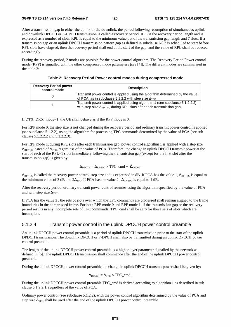
After a transmission gap in either the uplink or the downlink, the period following resumption of simultaneous uplink and downlink DPCCH or F-DPCH transmission is called a recovery period. RPL is the recovery period length and is expressed as a number of slots. RPL is equal to the minimum value out of the transmission gap length and 7 slots. If a transmission gap or an uplink DPCCH transmission pattern gap as defined in subclause 6C.2 is scheduled to start before RPL slots have elapsed, then the recovery period shall end at the start of the gap, and the value of RPL shall be reduced accordingly.
During the recovery period, 2 modes are possible for the power control algorithm. The Recovery Period Power control mode (RPP) is signalled with the other compressed mode parameters (see [4]). The different modes are summarised in the table 2:
Table 2: Recovery Period Power control modes during compressed mode
Recovery Period power control mode Description
0 Transmit power control is applied using the algorithm determined by the value of PCA, as in subclause 5.1.2.2 with step size ∆TPC.
1 Transmit power control is applied using algorithm 1 (see subclause 5.1.2.2.2) with step size ∆RP-TPC during RPL slots after each transmission gap.
If DTX_DRX_mode=1, the UE shall behave as if the RPP mode is 0.
For RPP mode 0, the step size is not changed during the recovery period and ordinary transmit power control is applied (see subclause 5.1.2.2), using the algorithm for processing TPC commands determined by the value of PCA (see sub clauses 5.1.2.2.2 and 5.1.2.2.3).
For RPP mode 1, during RPL slots after each transmission gap, power control algorithm 1 is applied with a step size ∆RP-TPC instead of ∆TPC, regardless of the value of PCA. Therefore, the change in uplink DPCCH transmit power at the start of each of the RPL+1 slots immediately following the transmission gap (except for the first slot after the transmission gap) is given by:
∆DPCCH = ∆RP-TPC × TPC_cmd + ∆ PILOT
∆RP-TPC is called the recovery power control step size and is expressed in dB. If PCA has the value 1, ∆RP-TPC is equal to the minimum value of 3 dB and 2∆TPC. If PCA has the value 2 , ∆RP-TPC is equal to 1 dB.
After the recovery period, ordinary transmit power control resumes using the algorithm specified by the value of PCA and with step size ∆TPC.
If PCA has the value 2 , the sets of slots over which the TPC commands are processed shall remain aligned to the frame boundaries in the compressed frame. For both RPP mode 0 and RPP mode 1, if the transmission gap or the recovery period results in any incomplete sets of TPC commands, TPC_cmd shall be zero for those sets of slots which are incomplete.
5.1.2.4 Transmit power control in the uplink DPCCH power control preamble
An uplink DPCCH power control preamble is a period of uplink DPCCH transmission prior to the start of the uplink DPDCH transmission. The downlink DPCCH or F-DPCH shall also be transmitted during an uplink DPCCH power control preamble.
The length of the uplink DPCCH power control preamble is a higher layer parameter signalled by the network as defined in [5]. The uplink DPDCH transmission shall commence after the end of the uplink DPCCH power control preamble.
During the uplink DPCCH power control preamble the change in uplink DPCCH transmit power shall be given by:
∆DPCCH = ∆TPC × TPC_cmd.
During the uplink DPCCH power control preamble TPC_cmd is derived according to algorithm 1 as described in sub clause 5.1.2.2.1, regardless of the value of PCA.
Ordinary power control (see subclause 5.1.2.2), with the power control algorithm determined by the value of PCA and step size ∆TPC, shall be used after the end of the uplink DPCCH power control preamble.
ETSI
ETSI TS 125 214 V7.4.0 (2007-03) 213GPP TS 25.214 version 7.4.0 Release 7
5.1.2.5 Setting of the uplink DPCCH/DPDCH relative powers
5.1.2.5.1 General
The uplink DPCCH and DPDCH(s) are transmitted on different codes as defined in subclause 4.2.1 of [3]. In the case that at least one DPDCH is configured, the gain factors βc and βd may vary for each TFC. There are two ways of controlling the gain factors of the DPCCH code and the DPDCH codes for different TFCs in normal (non-compressed) frames:
− βc and βd are signalled for the TFC, or
− βc and βd is computed for the TFC, based on the signalled settings for a reference TFC.
Combinations of the two above methods may be used to associate βc and βd values to all TFCs in the TFCS. The two methods are described in subclauses 5.1.2.5.2 and 5.1.2.5.3 respectively. Several reference TFCs may be signalled from higher layers.
The gain factors may vary on radio frame basis depending on the current TFC used. Further, the setting of gain factors is independent of the inner loop power control.
After applying the gain factors, the UE shall scale the total transmit power of the DPCCH and DPDCH(s), such that the DPCCH output power follows the changes required by the power control procedure with power adjustments of ∆DPCCH dB, subject to the provisions of sub-clause 5.1.2.6.
The gain factors during compressed frames are based on the nominal power relation defined in normal frames, as specified in subclause 5.1.2.5.4.
5.1.2.5.2 Signalled gain factors
When the gain factors βc and βd are signalled by higher layers for a certain TFC, the signalled values are used directly for weighting of DPCCH and DPDCH(s). The variable Aj, called the nominal power relation is then computed as:
c
djA
ββ= .
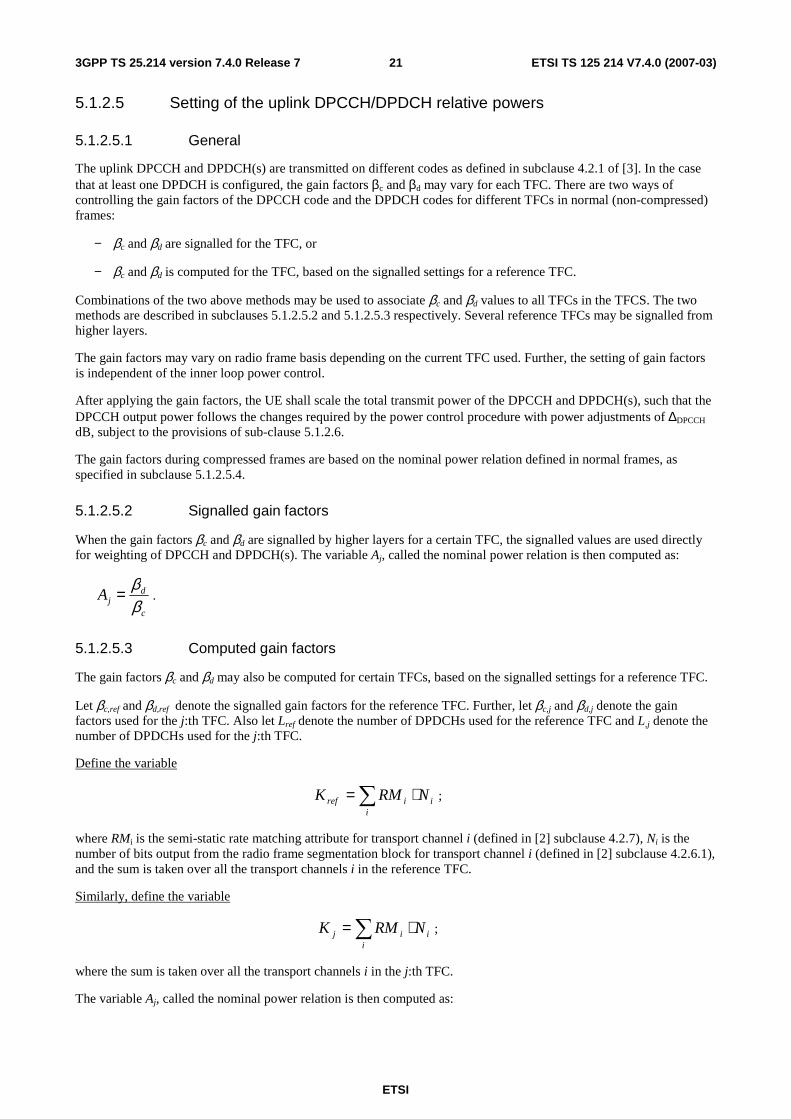
5.1.2.5.3 Computed gain factors
The gain factors βc and βd may also be computed for certain TFCs, based on the signalled settings for a reference TFC.
Let βc,ref and βd,ref denote the signalled gain factors for the reference TFC. Further, let βc,j and βd,j denote the gain factors used for the j:th TFC. Also let Lref denote the number of DPDCHs used for the reference TFC and L,j denote the number of DPDCHs used for the j:th TFC.
Define the variable
∑ ⋅=i
iiref NRMK ;
where RMi is the semi-static rate matching attribute for transport channel i (defined in [2] subclause 4.2.7), Ni is the number of bits output from the radio frame segmentation block for transport channel i (defined in [2] subclause 4.2.6.1), and the sum is taken over all the transport channels i in the reference TFC.
Similarly, define the variable
∑ ⋅=i
iij NRMK ;
where the sum is taken over all the transport channels i in the j:th TFC.
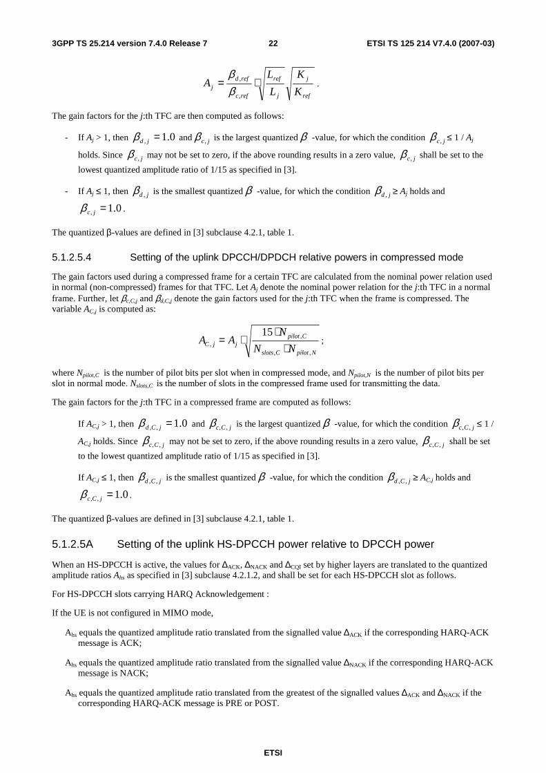
The variable Aj, called the nominal power relation is then computed as:
ETSI
ETSI TS 125 214 V7.4.0 (2007-03) 223GPP TS 25.214 version 7.4.0 Release 7
ref
j
j
ref
refc
refdj K
K
L
LA ⋅=
,
,
ββ
.
The gain factors for the j:th TFC are then computed as follows:
- If Aj > 1, then 0.1, =jdβ and jc,β is the largest quantized β -value, for which the condition jc,β ≤ 1 / Aj
holds. Since jc,β may not be set to zero, if the above rounding results in a zero value, jc,β shall be set to the
lowest quantized amplitude ratio of 1/15 as specified in [3].
- If Aj ≤ 1, then jd ,β is the smallest quantized β -value, for which the condition jd ,β ≥ Aj holds and
0.1, =jcβ .
The quantized β-values are defined in [3] subclause 4.2.1, table 1.
5.1.2.5.4 Setting of the uplink DPCCH/DPDCH relative powers in compressed mode
The gain factors used during a compressed frame for a certain TFC are calculated from the nominal power relation used in normal (non-compressed) frames for that TFC. Let Aj denote the nominal power relation for the j:th TFC in a normal frame. Further, let βc,C,j and βd,C,j denote the gain factors used for the j:th TFC when the frame is compressed. The variable AC,j is computed as:
NpilotCslots
CpilotjjC NN
NAA
,,
,,
15
⋅⋅
⋅= ;
where Npilot,C is the number of pilot bits per slot when in compressed mode, and Npilot,N is the number of pilot bits per slot in normal mode. Nslots,C is the number of slots in the compressed frame used for transmitting the data.
The gain factors for the j:th TFC in a compressed frame are computed as follows:
If AC,j > 1, then 0.1,, =jCdβ and jCc ,,β is the largest quantized β -value, for which the condition jCc ,,β ≤ 1 /
AC,j holds. Since jCc ,,β may not be set to zero, if the above rounding results in a zero value, jCc ,,β shall be set
to the lowest quantized amplitude ratio of 1/15 as specified in [3].
If AC,j ≤ 1, then jCd ,,β is the smallest quantized β -value, for which the condition jCd ,,β ≥ AC,j holds and
0.1,, =jCcβ .
The quantized β-values are defined in [3] subclause 4.2.1, table 1.
5.1.2.5A Setting of the uplink HS-DPCCH power relative to DPCCH power
When an HS-DPCCH is active, the values for ∆ACK, ∆NACK and ∆CQI set by higher layers are translated to the quantized amplitude ratios Ahs as specified in [3] subclause 4.2.1.2, and shall be set for each HS-DPCCH slot as follows.
For HS-DPCCH slots carrying HARQ Acknowledgement :
If the UE is not configured in MIMO mode,
Ahs equals the quantized amplitude ratio translated from the signalled value ∆ACK if the corresponding HARQ-ACK message is ACK;
Ahs equals the quantized amplitude ratio translated from the signalled value ∆NACK if the corresponding HARQ-ACK message is NACK;
Ahs equals the quantized amplitude ratio translated from the greatest of the signalled values ∆ACK and ∆NACK if the corresponding HARQ-ACK message is PRE or POST.
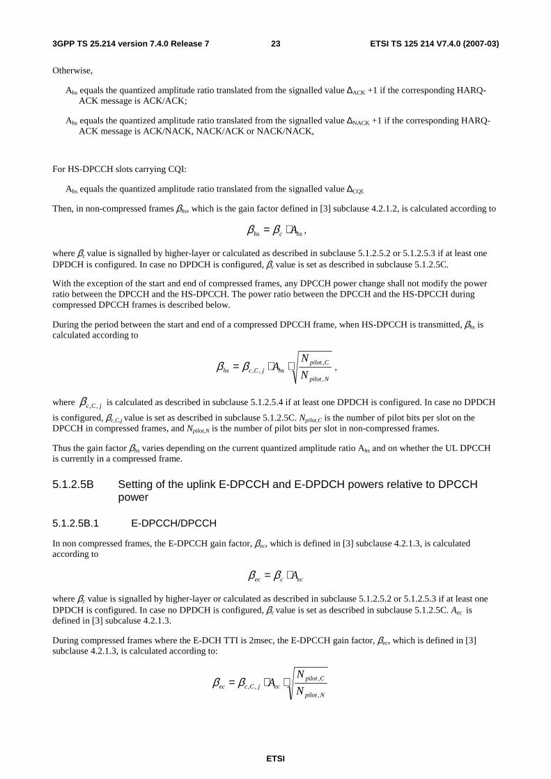
ETSI
ETSI TS 125 214 V7.4.0 (2007-03) 233GPP TS 25.214 version 7.4.0 Release 7
Otherwise,
Ahs equals the quantized amplitude ratio translated from the signalled value ∆ACK +1 if the corresponding HARQ-ACK message is ACK/ACK;
Ahs equals the quantized amplitude ratio translated from the signalled value ∆NACK +1 if the corresponding HARQ-ACK message is ACK/NACK, NACK/ACK or NACK/NACK,
For HS-DPCCH slots carrying CQI:
Ahs equals the quantized amplitude ratio translated from the signalled value ∆CQI.
Then, in non-compressed frames βhs, which is the gain factor defined in [3] subclause 4.2.1.2, is calculated according to
hschs A⋅= ββ ,
where βc value is signalled by higher-layer or calculated as described in subclause 5.1.2.5.2 or 5.1.2.5.3 if at least one DPDCH is configured. In case no DPDCH is configured, βc value is set as described in subclause 5.1.2.5C.
With the exception of the start and end of compressed frames, any DPCCH power change shall not modify the power ratio between the DPCCH and the HS-DPCCH. The power ratio between the DPCCH and the HS-DPCCH during compressed DPCCH frames is described below.
During the period between the start and end of a compressed DPCCH frame, when HS-DPCCH is transmitted, βhs is calculated according to
Npilot
CpilothsjCchs N
NA
,
,,, ⋅⋅= ββ ,
where jCc ,,β is calculated as described in subclause 5.1.2.5.4 if at least one DPDCH is configured. In case no DPDCH
is configured, βc,C,j value is set as described in subclause 5.1.2.5C. Npilot,C is the number of pilot bits per slot on the DPCCH in compressed frames, and Npilot,N is the number of pilot bits per slot in non-compressed frames.
Thus the gain factor βhs varies depending on the current quantized amplitude ratio Ahs and on whether the UL DPCCH is currently in a compressed frame.
5.1.2.5B Setting of the uplink E-DPCCH and E-DPDCH powers relative to DPCCH power
5.1.2.5B.1 E-DPCCH/DPCCH
In non compressed frames, the E-DPCCH gain factor, βec, which is defined in [3] subclause 4.2.1.3, is calculated according to
eccec A⋅= ββ
where βc value is signalled by higher-layer or calculated as described in subclause 5.1.2.5.2 or 5.1.2.5.3 if at least one DPDCH is configured. In case no DPDCH is configured, βc value is set as described in subclause 5.1.2.5C. Aec is defined in [3] subcaluse 4.2.1.3.
During compressed frames where the E-DCH TTI is 2msec, the E-DPCCH gain factor, βec, which is defined in [3] subclause 4.2.1.3, is calculated according to:
Npilot
CpilotecjCcec N
NA
,
,,, ⋅⋅= ββ
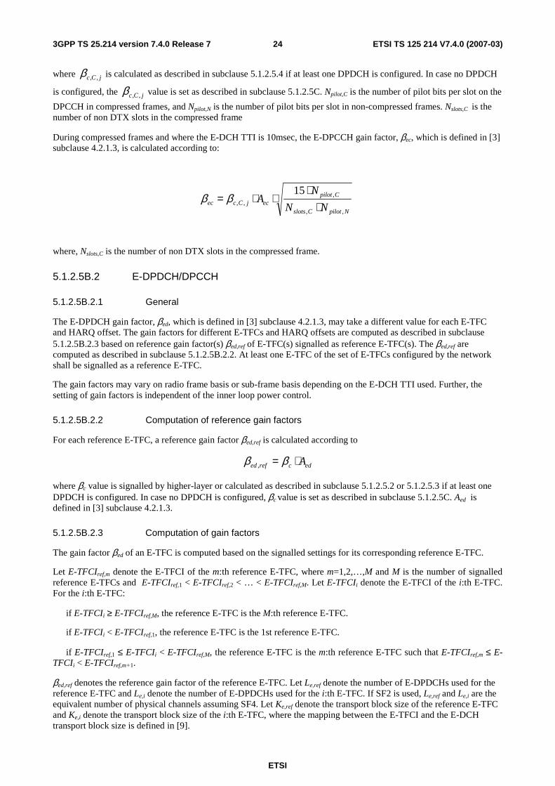
ETSI
ETSI TS 125 214 V7.4.0 (2007-03) 243GPP TS 25.214 version 7.4.0 Release 7
where jCc ,,β is calculated as described in subclause 5.1.2.5.4 if at least one DPDCH is configured. In case no DPDCH
is configured, the jCc ,,β value is set as described in subclause 5.1.2.5C. Npilot,C is the number of pilot bits per slot on the
DPCCH in compressed frames, and Npilot,N is the number of pilot bits per slot in non-compressed frames. Nslots,C is the number of non DTX slots in the compressed frame
During compressed frames and where the E-DCH TTI is 10msec, the E-DPCCH gain factor, βec, which is defined in [3] subclause 4.2.1.3, is calculated according to:
NpilotCslots
CpilotecjCcec NN
NA
,,
,,,
15
⋅⋅
⋅⋅= ββ
where, Nslots,C is the number of non DTX slots in the compressed frame.
5.1.2.5B.2 E-DPDCH/DPCCH
5.1.2.5B.2.1 General
The E-DPDCH gain factor, βed, which is defined in [3] subclause 4.2.1.3, may take a different value for each E-TFC and HARQ offset. The gain factors for different E-TFCs and HARQ offsets are computed as described in subclause 5.1.2.5B.2.3 based on reference gain factor(s) βed,ref of E-TFC(s) signalled as reference E-TFC(s). The βed,ref are computed as described in subclause 5.1.2.5B.2.2. At least one E-TFC of the set of E-TFCs configured by the network shall be signalled as a reference E-TFC.
The gain factors may vary on radio frame basis or sub-frame basis depending on the E-DCH TTI used. Further, the setting of gain factors is independent of the inner loop power control.
5.1.2.5B.2.2 Computation of reference gain factors
For each reference E-TFC, a reference gain factor βed,ref is calculated according to
edcrefed A⋅= ββ ,
where βc value is signalled by higher-layer or calculated as described in subclause 5.1.2.5.2 or 5.1.2.5.3 if at least one DPDCH is configured. In case no DPDCH is configured, βc value is set as described in subclause 5.1.2.5C. Aed is defined in [3] subclause 4.2.1.3.
5.1.2.5B.2.3 Computation of gain factors
The gain factor βed of an E-TFC is computed based on the signalled settings for its corresponding reference E-TFC.
Let E-TFCIref,m denote the E-TFCI of the m:th reference E-TFC, where m=1,2,…,M and M is the number of signalled reference E-TFCs and E-TFCIref,1 < E-TFCIref,2 < … < E-TFCIref,M. Let E-TFCIi denote the E-TFCI of the i:th E-TFC. For the i:th E-TFC:
if E-TFCIi ≥ E-TFCIref,M, the reference E-TFC is the M:th reference E-TFC.
if E-TFCIi < E-TFCIref,1, the reference E-TFC is the 1st reference E-TFC.
if E-TFCIref,1 ≤ E-TFCIi < E-TFCIref,M, the reference E-TFC is the m:th reference E-TFC such that E-TFCIref,m ≤ E-TFCIi < E-TFCIref,m+1.
βed,ref denotes the reference gain factor of the reference E-TFC. Let Le,ref denote the number of E-DPDCHs used for the reference E-TFC and Le,i denote the number of E-DPDCHs used for the i:th E-TFC. If SF2 is used, Le,ref and Le,i are the equivalent number of physical channels assuming SF4. Let Ke,ref denote the transport block size of the reference E-TFC and Ke,i denote the transport block size of the i:th E-TFC, where the mapping between the E-TFCI and the E-DCH transport block size is defined in [9].
ETSI
ETSI TS 125 214 V7.4.0 (2007-03) 253GPP TS 25.214 version 7.4.0 Release 7
For the i:th E-TFC, the temporary variable βed,i,harq is then computed as:
∆
⋅= 20
,
,
,
,
,,,10
harq
refe
ie
ie
refe
refedharqied K
K
L
Lββ
where the HARQ offset ∆harq is defined in [3] subclause 4.2.1.3.
For the i:th E-TFC, the unquantized gain factor βed,k,i,uq for the k:th E-DPDCH (denoted E-DPDCHk in [3] subclause
4.2.1.3) shall be set to harqied ,,2 β× if the spreading factor for E-DPDCHk is 2 and to harqied ,,β otherwise.
If βed,k,i,uq/βc is less than the smallest quantized value of Table 1B.2 in [3] subclause 4.2.1.3, then the gain factor of E-DPDCHk, βed,k is set such that βed,k/βc is the smallest quantized value of Table 1B.2 in [3] subclause 4.2.1.3. Otherwise, βed,k is set such that βed,k/βc is the largest quantized value of Table 1B.2 in [3] subclause 4.2.1.3, for which the condition βed,k ≤ βed,k,i,uq holds.
5.1.2.5B.2.4 E-DPDCH/DPCCH adjustments relating to compressed mode
The gain factor applied to E-DPDCH is adjusted as a result of compressed mode operation in the following cases:
• E-DCH transmissions that overlap a compressed frame
• For 10msec E-DCH TTI case, retransmissions that do not themselves overlap a compressed frame, but for which the corresponding initial transmission overlapped a compressed frame.
The gain factors used during a compressed frame for a certain E-TFC are calculated from the nominal power relation used in normal (non-compressed) frames for that E-TFC. When the frame is compressed, the gain factor used for the i:th E-TFC is derived from βed,C,i as described below.
When the E-DCH TTI is 2msec, βed,C,i shall be calculated as:
Npilot
Cpilot
refe
ie
ie
refe
edjCciCed N
N
K
K
L
LA
harq
,
,20
,
,
,
,
,,,, 10 ⋅⋅⋅⋅⋅=
∆
ββ ,
where jCc ,,β is calculated for the j:th TFC as described in subclause 5.1.2.5.4 if at least one DPDCH is configured. In
case no DPDCH is configured, the jCc ,,β value is set as described in subclause 5.1.2.5C. Aed is as defined in [3]
subcaluse 4.2.1.3, Le,ref, Le,i, Ke,ref and Ke,i are as defined in subclause 5.1.2.5B.2.3, ∆harq is as defined in [3] subclause 4.2.1.3, Npilot,C is the number of pilot bits per slot on the DPCCH in compressed frames, and Npilot,N is the number of pilot bits per slot in non-compressed frames.
When the E-DCH TTI is 10msec and the current frame is compressed, βed,C,i shall be calculated as follows:
NpilotIslots
Cpilot
refe
ie
iIe
refeedjCciCed NN
N
K
K
L
LA
harq
,,
,20
,
,
,,
,,,,,
1510
⋅⋅
⋅⋅⋅⋅⋅=
∆
ββ ,
where Le,I,i denotes the number of E-DPDCHs used for the i:th E-TFC in the first frame used for transmitting the data and Nslots,I is the number of non DTX slots in the first frame used for transmitting the data.
For the i:th E-TFC, the unquantized gain factor βed, k,i,uq for the k:th E-DPDCH (denoted E-DPDCHk in [3] subclause
4.2.1.3) shall be set to iCed ,,2 β× if the spreading factor for E-DPDCHk is 2 and to iCed ,,β otherwise.
ETSI
ETSI TS 125 214 V7.4.0 (2007-03) 263GPP TS 25.214 version 7.4.0 Release 7
Quantization may be applied as follows: If βed, ,k,i,uq/βc,C,j is less than the smallest quantized value of Table 1B.2 in [3] subclause 4.2.1.3, then the gain factor of E-DPDCHk, βed,k is set such that βed,k/βc,C,j is the smallest quantized value of Table 1B.2 in [3] subclause 4.2.1.3. Otherwise, βed,k is set such that βed,k/βc,C,j is the largest quantized value of Table 1B.2 in [3] subclause 4.2.1.3, for which the condition βed,k ≤ βed, k,i,uq holds.
If quantization is not applied, βed,k shall be set to βed, k,i,uq.
When the E-DCH TTI is 10msec and the current frame is not compressed, but is a retransmission for which the corresponding first transmission was compressed, the gain factor used for the k:th E-DPDCH for the i:th E-TFC is derived from βed,R,i as follows:
∆
⋅= 20
,,
,
,,
,,,, 10
15harq
Islotsrefe
ie
iIe
referefediRed NK
K
L
Lββ
where βed,ref is the reference gain factor used for the i:th E-TFC as defined in subclause 5.1.2.5B.2.3; Le,ref, Ke,ref and Ke,i are as defined in subclause 5.1.2.5B.2.3, ∆harq is as defined in [3] subclause 4.2.1.3, and Le,I,i and Nslots,I are as defined above.
For the i:th E-TFC, the unquantized gain factor βed, k,i,uq for the k:th E-DPDCH (denoted E-DPDCHk in [3] subclause
4.2.1.3) shall be set to iRed ,,2 β× if the spreading factor for E-DPDCHk is 2 and to iRed ,,β otherwise.
Quantization may be applied as follows: If βed, k,i,uq/βc is less than the smallest quantized value of Table 1B.2 in [3] subclause 4.2.1.3, then the gain factor of E-DPDCHk, βed,k is set such that βed,k/βc is the smallest quantized value of Table 1B.2 in [3] subclause 4.2.1.3. Otherwise, βed,k is set such that βed,k/βc is the largest quantized value of Table 1B.2 in [3] subclause 4.2.1.3, for which the condition βed,k ≤ βed, k,i,uq holds.
If quantization is not applied, βed,k shall be set to βed, k,i,uq.
5.1.2.5C Setting of the uplink DPCCH gain factor when no DPDCH is configured
In the case that no DPDCH is configured, the gain factor βc is equal to 1. During a compressed frame, the gain factor βc,C,j is also equal to 1.
5.1.2.6 Maximum and minimum power limits
When E-DCH is not configured, in the case that the total UE transmit power (after applying DPCCH power adjustments and gain factors) would exceed the maximum allowed value, the UE shall apply additional scaling to the total transmit power so that it is equal to the maximum allowed power. This additional scaling shall be such that the power ratio between DPCCH and DPDCH and also DPCCH and HS-DPCCH remains as required by sub-clause 5.1.2.5 and 5.1.2.5A.
When E-DCH is configured, if the total UE transmit power (after applying DPCCH power adjustments and gain factors) would exceed the maximum allowed value, the UE shall firstly reduce all the E-DPDCH gain factors βed,k by an equal scaling factor to respective values βed,k,reduced so that the total transmit power would be equal to the maximum allowed power. After calculating the reduced E-DPDCH gain factors, quantization according to table 1B.2 in [3] subclause 4.2.1.3 may be applied, where each βed,k,reduced is quantized such that βed,k/βc is the largest quantised value for which the condition βed,k ≤ βed,k,reduced holds.
In case a DPDCH is configured, if any βed,k,reduced/βc is less than the smallest quantized value of Table 1B.2 in [3] subclause 4.2.1.3, DTX may be used on that E-DPDCH (E-DPCCH is, however still transmitted using βec).
In case no DPDCH is configured, if any βed,k,reduced/βc is less than (8/15)/βc, that βed,k shall be set to βed,k,min such that βed,k,min/βc = min ((8/15)/βc, βed,k,original/βc), where βed,k,original denotes the E-DPDCH gain factor before reduction.
ETSI
ETSI TS 125 214 V7.4.0 (2007-03) 273GPP TS 25.214 version 7.4.0 Release 7
In the following cases, the UE shall then apply additional scaling to the total transmit power so that it is equal to the maximum allowed power:
- if a DPDCH is configured and the total UE transmit power would still exceed the maximum allowed value even though DTX is used on all E-DPDCHs;
- if no DPDCH is configured and the total UE transmit power would still exceed the maximum allowed value even though βed,k is equal to βed,k,min for all k.
Any additional scaling of the total transmit power as described above shall be such that the power ratio between DPCCH and DPDCH, between DPCCH and HS-DPCCH, and between DPCCH and E-DPCCH, remains as required by sub-clauses 5.1.2.5, 5.1.2.5A and 5.1.2.5B.1, and such that the power ratio between each E-DPDCH and DPCCH remains as required by βed,k,min/βc if DTX is not used on E-DPDCH. Any slot-level scaling of βed or DTX of E-DPDCH as described above is applied at layer 1 only and is transparent to higher layers.
Any scaling, and any reduction in the E-DPDCH gain factor as described above, shall only be applied or changed at a DPCCH slot boundary. In order that the total UE transmit power does not exceed the maximum allowed value the scaling or E-DPDCH gain factor reduction shall be computed using the maximum HS-DPCCH power transmitted in the next DPCCH slot. In the case that either an ACK or a NACK transmission will start during the next DPCCH slot, the maximum HS-DPCCH power shall be computed using one of the following:
(a) whichever of ∆ACK and ∆NACK will be used according to whether the transmission will be ACK or NACK, or
(b) whichever of ∆ACK and ∆NACK is the largest.
When transmitting on a DPCH the UE is not required to be capable of reducing its total transmit power below the minimum level required in [7]. However, it may do so, provided that the power ratio between DPCCH and DPDCH and also between DPCCH and HS-DPCCH remains as specified in sub clause 5.1.2.5 and 5.1.2.5A. Some further regulations also apply as follows: In the case that the total UE transmit power (after applying DPCCH power adjustments and gain factors) would be at or below the total transmit power in the previously transmitted slot and also at or below the required minimum power specified in [7], the UE may apply additional scaling to the total transmit power, subject to the following restrictions:
- The total transmit power after applying any additional scaling shall not exceed the required minimum power, nor the total transmit power in the previously transmitted slot;
- The magnitude of any reduction in total transmit power between slots after applying any additional scaling shall not exceed the magnitude of the calculated power reduction before the additional scaling.
In the case that the total UE transmit power in the previously transmitted slot is at or below the required minimum power specfied in [7] and the DPCCH power adjustment and gain factors for the current slot would result in an increase in total power, then no additional scaling shall be used (i.e. power control shall operate as normal).
If the UE applies any additional scaling to the total transmit power as described above, this scaling shall be included in the computation of any DPCCH power adjustments to be applied in the next transmitted slot.
5.1.3 Void
5.2 Downlink power control The transmit power of the downlink channels is determined by the network. In general the ratio of the transmit power between different downlink channels is not specified and may change with time. However, regulations exist as described in the following subclauses.
Higher layer power settings shall be interpreted as setting of the total power, i.e. the sum of the power from the two antennas in case of transmit diversity.
ETSI
ETSI TS 125 214 V7.4.0 (2007-03) 283GPP TS 25.214 version 7.4.0 Release 7
5.2.1 DPCCH/DPDCH/F-DPCH
5.2.1.1 General
The downlink transmit power control procedure controls simultaneously the power of a DPCCH and its corresponding DPDCHs. The power control loop adjusts the power of the DPCCH and DPDCHs with the same amount, i.e. the relative power difference between the DPCCH and DPDCHs is not changed. In case of F-DPCH, the power control loop adjusts the F-DPCH power.
For DPCH, the relative transmit power offset between DPCCH fields and DPDCHs is determined by the network. The TFCI, TPC and pilot fields of the DPCCH are offset relative to the DPDCHs power by PO1, PO2 and PO3 dB respectively. The power offsets may vary in time. The method for controlling the power offsets within UTRAN is specified in [6]. The power offsets PO1, PO2 and PO3 do not apply to F-DPCH.
5.2.1.2 Ordinary transmit power control
5.2.1.2.1 UE behaviour
The UE shall generate TPC commands to control the network transmit power and send them in the TPC field of the uplink DPCCH. An example on how to derive the TPC commands in given in Annex B.2.
The UE shall check the downlink power control mode (DPC_MODE) before generating the TPC command:
- if DPC_MODE = 0 : the UE sends a unique TPC command in each slot and the TPC command generated is transmitted in the first available TPC field in the uplink DPCCH;
- if DPC_MODE = 1 : the UE repeats the same TPC command over 3 slots and the new TPC command is transmitted such that there is a new command at the beginning of the frame, unless DTX_DRX_mode=1, in which case the UE shall behave as for DPC_MODE=0.
The DPC_MODE parameter is a UE specific parameter controlled by the UTRAN.
The UE shall not make any assumptions on how the downlink power is set by UTRAN, in order to not prohibit usage of other UTRAN power control algorithms than what is defined in subclause 5.2.1.2.2.
5.2.1.2.1.1 F-DPCH quality target control
The UTRAN sets a quality target for the F-DPCH. The UE autonomously sets a SIR target value and adjusts it in order to achieve the same quality as the quality target set by UTRAN. The quality target is set as a downlink TPC command error rate target value for the F-DPCH belonging to the radio link from the HS-DSCH serving cell as signalled by the UTRAN. The UE shall set the SIR target when the F-DPCH has been setup or reconfigured. It shall not increase the SIR target value before the power control has converged on the current value. The UE may estimate whether the power control has converged on the current value, by comparing the averaged measured SIR to the SIR target value.
5.2.1.2.2 UTRAN behaviour
Upon receiving the TPC commands UTRAN shall adjust its downlink DPCCH/DPDCH or F-DPCH power accordingly. For DPC_MODE = 0, and for DPC_MODE=1 if DTX_DRX_mode=1,UTRAN shall estimate the transmitted TPC command TPCest to be 0 or 1, and shall update the power every transmitted slot. If DPC_MODE = 1 and DTX_DRX_mode=0, UTRAN shall estimate the transmitted TPC command TPCest over three slots to be 0 or 1, and shall update the power every three slots.
After estimating the k:th TPC command, UTRAN shall adjust the current downlink power P(k-1) [dB] to a new power P(k) [dB] according to the following formula:
P(k) = P(k - 1) + PTPC(k) + Pbal(k),
where PTPC(k) is the k:th power adjustment due to the inner loop power control, and Pbal(k) [dB] is a correction according to the downlink power control procedure for balancing radio link powers towards a common reference power. The power balancing procedure and control of the procedure is described in [6].
PTPC(k) is calculated according to the following.
ETSI
ETSI TS 125 214 V7.4.0 (2007-03) 293GPP TS 25.214 version 7.4.0 Release 7
If the value of Limited Power Increase Used parameter is 'Not used', then
=−=+
=0)(TPCif∆
1)(TPCif∆)(P
estTPC
estTPCTPC k
kk , [dB]. (1)
If the value of Limited Power Increase Used parameter is 'Used', then the k:th inner loop power adjustment shall be calculated as:
=≥∆+∆=<∆+∆=
∆−
∆+=
0)(TPC if
e_LimitPower_Rais)( and 1)(TPC if
e_LimitPower_Rais)( and 1)(TPC if
0)(
est
est
est
k
kk
kk
kP TPCsum
TPCsum
TPC
TPC
TPC , [dB] (2)
where
∑−
−==∆
1
indow_Sizeveraging_WDL_Power_A
)()(k
kiTPCsum iPk
is the temporary sum of the last DL_Power_Averaging_Window_Size inner loop power adjustments (in dB).
For the first (DL_Power_Averaging_Window_Size – 1) adjustments after the activation of the limited power increase method, formula (1) shall be used instead of formula (2). Power_Raise_Limit and DL_Power_Averaging_Window_Size are parameters configured in the UTRAN.
The power control step size ∆TPC can take four values: 0.5, 1, 1.5 or 2 dB. It is mandatory for UTRAN to support ∆TPC of 1 dB, while support of other step sizes is optional.
In addition to the above described formulas on how the downlink power is updated, the restrictions below apply.
In case of congestion (commanded power not available), UTRAN may disregard the TPC commands from the UE.
The average power of transmitted DPDCH symbols over one timeslot shall not exceed Maximum_DL_Power (dB), nor shall it be below Minimum_DL_Power (dB). Transmitted DPDCH symbol means here a complex QPSK symbol before spreading which does not contain DTX. Maximum_DL_Power (dB) and Minimum_DL_Power (dB) are power limits for one channelisation code, relative to the primary CPICH power [6].
In case of F-DPCH, the power of the transmitted symbol over one timeslot for a given UE shall not exceed Maximum_DL_Power (dB), nor shall it be below Minimum_DL_Power (dB). Transmitted symbol means here a complex QPSK symbol before spreading which does not contain DTX.
In the case that UL_DTX_mode=1 (see section 6C), if no uplink TPC command is received due to uplink DPCCH transmission pattern gap as defined in subclause 6C.2.1, PTPC(k) derived by the Node B shall be set to zero.
5.2.1.3 Power control in compressed mode
The aim of downlink power control in uplink or/and downlink compressed mode is to recover as fast as possible a signal-to-interference ratio (SIR) close to the target SIR after each transmission gap.
The UE behaviour is the same in compressed mode as in normal mode, described in subclause 5.2.1.2, except that the target SIR for a DPCH is offset by higher layer signalling. However due to transmission gaps in uplink compressed frames there may be incomplete sets of TPC commands when DPC_MODE=1.
UTRAN behaviour is as stated in section 5.2.1.2.2 except for DPC_MODE = 1 where missing TPC commands in the UL may lead the UTRAN to changing its power more frequently than every 3 slots.
In compressed mode, compressed frames may occur in either the uplink or the downlink or both. In downlink compressed frames, the transmission of downlink DPDCH(s), DPCCH and F-DPCH shall be stopped during transmission gaps.
The power of the DPCCH and DPDCH in the first slot after the transmission gap, or the power of the F-DPCH in the first slot after the transmission gap, should be set to the same value as in the slot just before the transmission gap.
ETSI
ETSI TS 125 214 V7.4.0 (2007-03) 303GPP TS 25.214 version 7.4.0 Release 7
During compressed mode except during downlink transmission gaps, UTRAN shall estimate the k:th TPC command and adjust the current downlink power P(k-1) [dB] to a new power P(k) [dB] according to the following formula:
P(k) = P(k - 1) + PTPC(k) + PSIR(k) + Pbal(k),
where PTPC(k) is the k:th power adjustment due to the inner loop power control, PSIR(k) is the k-th power adjustment due to the downlink target SIR variation, and Pbal(k) [dB] is a correction according to the downlink power control procedure for balancing radio link powers towards a common reference power. The power balancing procedure and control of the procedure is described in [6].
Due to transmission gaps in uplink compressed frames, there may be missing TPC commands in the uplink.
For DPC_MODE = 0, and for DPC_MODE=1 if DTX_DRX_mode=1, if no uplink TPC command is received, PTPC(k) derived by the Node B shall be set to zero. Otherwise, PTPC(k) is calculated the same way as in normal mode (see sub-clause 5.2.1.2.2) but with a step size ∆STEP instead of ∆TPC.
For DPC_MODE = 1 if DTX_DRX_mode=0, the sets of slots over which the TPC commands are processed shall remain aligned to the frame boundaries in the compressed frame. If this results in an incomplete set of TPC commands, the UE shall transmit the same TPC commands in all slots of the incomplete set.
The power control step size ∆STEP = ∆RP-TPC during RPL slots after each transmission gap and ∆STEP = ∆TPC otherwise, where:
- RPL is the recovery period length and is expressed as a number of slots. RPL is equal to the minimum value out of the transmission gap length and 7 slots. If a transmission gap or an uplink DPCCH transmission pattern gap as defined in subclause 6C.2 is scheduled to start before RPL slots have elapsed, then the recovery period shall end at the start of the gap, and the value of RPL shall be reduced accordingly.
- ∆RP-TPC is called the recovery power control step size and is expressed in dB. ∆RP-TPC is equal to the minimum value of 3 dB and 2∆TPC.
For F-DPCH, PSIR(k) = 0.
For DPCH, the power offset PSIR(k) = δPcurr - δPprev, where δPcurr and δPprev are respectively the value of δP in the current slot and the most recently transmitted slot and δP is computed as follows:
δP = max (∆P1_compression, …, ∆Pn_compression) + ∆P1_coding + ∆P2_coding
where n is the number of different TTI lengths amongst TTIs of all TrChs of the CCTrCh, where ∆P1_coding and ∆P2_coding are computed from uplink parameters DeltaSIR1, DeltaSIR2, DeltaSIRafter1, DeltaSIRafter2 signaled by higher layers as:
- ∆P1_coding = DeltaSIR1 if the start of the first transmission gap in the transmission gap pattern is within the current frame and DTX_DRX_mode=0.
- ∆P1_coding = DeltaSIRafter1 if the current frame just follows a frame containing the start of the first transmission gap in the transmission gap pattern and DTX_DRX_mode=0.
- ∆P2_coding = DeltaSIR2 if the start of the second transmission gap in the transmission gap pattern is within the current frame and DTX_DRX_mode=0 .
- ∆P2_coding = DeltaSIRafter2 if the current frame just follows a frame containing the start of the second transmission gap in the transmission gap pattern and DTX_DRX_mode=0.
- ∆P1_coding = 0 dB and ∆P2_coding = 0 dB in all other cases.
and ∆Pi_compression is defined by :
- ∆Pi_compression = 3 dB for downlink frames compressed by reducing the spreading factor by 2.
- ∆Pi_compression = 0 dB in all other cases.
In case several compressed mode patterns are used simultaneously, a δP offset is computed for each compressed mode pattern and the sum of all δP offsets is applied to the frame.
ETSI
ETSI TS 125 214 V7.4.0 (2007-03) 313GPP TS 25.214 version 7.4.0 Release 7
For all time slots except those in transmissions gaps, the average power of transmitted DPDCH symbols over one timeslot shall not exceed Maximum_DL_Power (dB) by more than δPcurr, nor shall it be below Minimum_DL_Power (dB). Transmitted DPDCH symbol means here a complex QPSK symbol before spreading which does not contain DTX. Maximum_DL_Power (dB) and Minimum_DL_Power (dB) are power limits for one channelisation code, relative to the primary CPICH power [6].
For F-DPCH, for all time slots except those in transmissions gaps the power of the transmitted symbol over one timeslot for a given UE shall not exceed Maximum_DL_Power (dB), nor shall it be below Minimum_DL_Power (dB). Transmitted symbol means here a complex QPSK symbol before spreading which does not contain DTX.
5.2.1.4 Void
5.2.2 Void
5.2.3 Void
5.2.4 AICH
The UE is informed about the relative transmit power of the AICH (measured as the power per transmitted acquisition indicator) compared to the primary CPICH transmit power by the higher layers.
5.2.5 PICH
The UE is informed about the relative transmit power of the PICH (measured as the power over the paging indicators) compared to the primary CPICH transmit power by the higher layers.
5.2.6 S-CCPCH
The TFCI and pilot fields may be offset relative to the power of the data field. The power offsets may vary in time.
5.2.7 Void
5.2.8 Void
5.2.9 Void
5.2.10 HS-SCCH
The HS-SCCH power control is under the control of the node B. It may e.g. follow the power control commands sent by the UE to the node B or any other power control procedure applied by the node B.
5.2.11 HS-PDSCH
The HS-PDSCH power control is under the control of the node B. When the HS-PDSCH is transmitted using 16QAM or 64QAM, the UE may assume that the power is kept constant during the corresponding HS-DSCH subframe.
In case of multiple HS-PDSCH transmission to one UE, all the HS-PDSCHs intended for that UE shall be transmitted with equal power.
The sum of the powers used by all HS-PDSCHs, HS-SCCHs, E-AGCHs, E-RGCHs and E-HICHs in a cell shall not exceed the value of HS-PDSCH, HS-SCCH, E-AGCH, E-RGCH and E-HICH Total Power if signaled by higher layers [6].
ETSI
ETSI TS 125 214 V7.4.0 (2007-03) 323GPP TS 25.214 version 7.4.0 Release 7
5.2.12 E-AGCH
The E-AGCH power control is under the control of the node B. It may e.g. follow the power control commands sent by the UE to the node B or any other power control procedure applied by the node B.
5.2.13 E-HICH
The E-HICH power control is under the control of the node B. It may e.g. follow the power control commands sent by the UE to the node B or any other power control procedure applied by the node B.
5.2.14 E-RGCH
The E-RGCH power control is under the control of the node B. It may e.g. follow the power control commands sent by the UE to the node B or any other power control procedure applied by the node B.
5.2.15 MICH
The UE is informed about the relative transmit power of the MICH (measured as the power over the notification indicators) compared to the primary CPICH transmit power by the higher layers.
6 Random access procedure
6.1 Physical random access procedure The physical random access procedure described in this subclause is initiated upon request from the MAC sublayer (cf. [9]).
Before the physical random-access procedure can be initiated, Layer 1 shall receive the following information from the higher layers (RRC):
- The preamble scrambling code.
- The message length in time, either 10 or 20 ms.
- The AICH_Transmission_Timing parameter [0 or 1].
- The set of available signatures and the set of available RACH sub-channels for each Access Service Class (ASC). Sub-channels are defined in subclause 6.1.1.
- The power-ramping factor Power Ramp Step [integer > 0].
- The parameter Preamble Retrans Max [integer > 0].
- The initial preamble power Preamble_Initial_Power.
- The Power offset P p-m = Pmessage-control – Ppreamble, measured in dB, between the power of the last transmitted preamble and the control part of the random-access message.
- The set of Transport Format parameters. This includes the power offset between the data part and the control part of the random-access message for each Transport Format.
Note that the above parameters may be updated from higher layers before each physical random access procedure is initiated.
At each initiation of the physical random access procedure, Layer 1 shall receive the following information from the higher layers (MAC):
- The Transport Format to be used for the PRACH message part.
- The ASC of the PRACH transmission.
ETSI
ETSI TS 125 214 V7.4.0 (2007-03) 333GPP TS 25.214 version 7.4.0 Release 7
- The data to be transmitted (Transport Block Set).
The physical random-access procedure shall be performed as follows:
1 Derive the available uplink access slots, in the next full access slot set, for the set of available RACH sub-channels within the given ASC with the help of subclauses 6.1.1. and 6.1.2. Randomly select one access slot among the ones previously determined. If there is no access slot available in the selected set, randomly select one uplink access slot corresponding to the set of available RACH sub-channels within the given ASC from the next access slot set. The random function shall be such that each of the allowed selections is chosen with equal probability.
2 Randomly select a signature from the set of available signatures within the given ASC. The random function shall be such that each of the allowed selections is chosen with equal probability.
3 Set the Preamble Retransmission Counter to Preamble Retrans Max.
4 If the Preamble_Initial_Power is below the minimum level required in [7], set the Commanded Preamble Power to a value, which shall be at or above the Preamble_Initial_Power and at or below the required minimum power specified in [7]. Otherwise set the parameter Commanded Preamble Power to Preamble_Initial_Power.
5 In the case that the Commanded Preamble Power exceeds the maximum allowed value, set the preamble transmission power to the maximum allowed power. In the case that the Commanded Preamble Power is below the minimum level required in [7], set the preamble transmission power to a value, which shall be at or above the Commanded Preamble Power and at or below the required minimum power specified in [7]. Otherwise set the preamble transmission power to the Commanded Preamble Power. Transmit a preamble using the selected uplink access slot, signature, and preamble transmission power.
6 If no positive or negative acquisition indicator (AI ≠ +1 nor –1) corresponding to the selected signature is detected in the downlink access slot corresponding to the selected uplink access slot:
6.1 Select the next available access slot in the set of available RACH sub-channels within the given ASC.
6.2 Randomly select a new signature from the set of available signatures within the given ASC. The random function shall be such that each of the allowed selections is chosen with equal probability.
6.3 Increase the Commanded Preamble Power by ∆P0 = Power Ramp Step [dB]. If the Commanded Preamble Power exceeds the maximum allowed power by 6dB, the UE may pass L1 status ("No ack on AICH") to the higher layers (MAC) and exit the physical random access procedure.
6.4 Decrease the Preamble Retransmission Counter by one.
6.5 If the Preamble Retransmission Counter > 0 then repeat from step 5. Otherwise pass L1 status ("No ack on AICH") to the higher layers (MAC) and exit the physical random access procedure.
7 If a negative acquisition indicator corresponding to the selected signature is detected in the downlink access slot corresponding to the selected uplink access slot, pass L1 status ("Nack on AICH received") to the higher layers (MAC) and exit the physical random access procedure.
8 Transmit the random access message three or four uplink access slots after the uplink access slot of the last transmitted preamble depending on the AICH transmission timing parameter. Transmission power of the control part of the random access message should be P p-m [dB] higher than the power of the last transmitted preamble. Transmission power of the data part of the random access message is set according to subclause 5.1.1.2.
9 Pass L1 status "RACH message transmitted" to the higher layers and exit the physical random access procedure.
6.1.1 RACH sub-channels
A RACH sub-channel defines a sub-set of the total set of uplink access slots. There are a total of 12 RACH sub-channels. RACH sub-channel #i (i = 0, …, 11) consists of the following uplink access slots:
- Uplink access slot #i leading by τp-a chips the downlink access slot #i contained within the 10 ms interval that is time aligned with P-CCPCH frames for which SFN mod 8 = 0 or SFN mod 8 = 1.
- Every 12th access slot relative to this access slot.
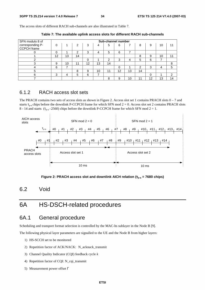
ETSI
ETSI TS 125 214 V7.4.0 (2007-03) 343GPP TS 25.214 version 7.4.0 Release 7
The access slots of different RACH sub-channels are also illustrated in Table 7.
Table 7: The available uplink access slots for different RACH sub-channels
Sub-channel number SFN modulo 8 of corresponding P-CCPCH frame
0 1 2 3 4 5 6 7 8 9 10 11
0 0 1 2 3 4 5 6 7 1 12 13 14 8 9 10 11 2 0 1 2 3 4 5 6 7 3 9 10 11 12 13 14 8 4 6 7 0 1 2 3 4 5 5 8 9 10 11 12 13 14 6 3 4 5 6 7 0 1 2 7 8 9 10 11 12 13 14
6.1.2 RACH access slot sets
The PRACH contains two sets of access slots as shown in Figure 2. Access slot set 1 contains PRACH slots 0 – 7 and starts τp-a chips before the downlink P-CCPCH frame for which SFN mod 2 = 0. Access slot set 2 contains PRACH slots 8 - 14 and starts (τp-a –2560) chips before the downlink P-CCPCH frame for which SFN mod 2 = 1.
AICH accessslots
10 ms
#0 #1 #2 #3 #14#13#12#11#10#9#8#7#6#5#4τp-a
#0 #1 #2 #3 #14#13#12#11#10#9#8#7#6#5#4
PRACHaccess slots
SFN mod 2 = 0 SFN mod 2 = 1
10 ms
Access slot set 1 Access slot set 2
Figure 2: PRACH access slot and downlink AICH relation (ττττp-a = 7680 chips)
6.2 Void
6A HS-DSCH-related procedures
6A.1 General procedure Scheduling and transport format selection is controlled by the MAC-hs sublayer in the Node B [9].
The following physical layer parameters are signalled to the UE and the Node B from higher layers:
1) HS-SCCH set to be monitored
2) Repetition factor of ACK/NACK: N_acknack_transmit
3) Channel Quality Indicator (CQI) feedback cycle k
4) Repetition factor of CQI: N_cqi_transmit
5) Measurement power offset Γ
ETSI
ETSI TS 125 214 V7.4.0 (2007-03) 353GPP TS 25.214 version 7.4.0 Release 7
6) Status of preamble/postamble transmission: HARQ_preamble_mode
7) Status of 64QAM configuration
8) Set of P-CPICH and/or S-CPICH (which shall be transmitted on the same scrambling code) that shall be used for HS-PDSCH demodulation in case the UE is configured in MIMO mode
9) The number N of dynamic single/dual CQI reports out of a sequence of M CQI reports in case the UE is configured in MIMO mode: N_cqi_typeA, M_cqi, respectively
10) Set of transport block sizes configured for HS-SCCH-less operation
11) Set of HS-PDSCHs configured for HS-SCCH-less operation
In addition, the layer 1 receives the status variables HS_SCCH_LESS_STATUS and DTX_DRX_STATUS, and the parameter Enabling_Delay, from higher layers.
If HS_SCCH_LESS_STATUS is TRUE then HS-SCCH_less_mode=1. Otherwise HS-SCCH_less_mode=0.
If DTX_DRX_STATUS is set to TRUE and Enabling_Delay radio frames have passed then DTX_DRX_mode=1. Otherwise DTX_DRX_mode=0.
6A.1.1 UE procedure for receiving HS-DSCH and HS-SCCH
NOTE: The Node B procedure for transmitting the HS-DSCH and the associated HS-SCCH is specified in subclause 6A.1.3.
In this sub-clause, sub-frame n on the HS-SCCHs refers to the sub-frame which is associated with sub-frame n on the HS-PDSCH as defined in [1], and sub-frame n on the HS-DPCCH refers to the sub-frame which is related to sub-frame n on the HS-PDSCH as defined in [1].
If the UE did not detect consistent control information intended for this UE on any of the HS-SCCHs in the HS-SCCH set in the immediately preceding subframe n – 1, the UE shall in sub-frame n monitor all HS-SCCHs in the HS-SCCH set. The maximum size of the HS-SCCH set is 4.
If 64QAM is not configured for the UE, then if the UE did detect consistent control information intended for this UE in the immediately preceding subframe n – 1, it is sufficient in sub-frame n to only monitor the same HS-SCCH used in the immediately preceding subframe n – 1. This rule applies regardless of the value of HS-SCCH_less_mode.
When the UE monitors HS-SCCHs, the UE shall only consider the control information to be consistent if either:
- the decoded 'channelization-code-set information' is lower than or equal to 'maximum number of HS-DSCH codes received' in its UE capability and the decoded 'modulation scheme information' is valid in terms of its UE capability,
or
- the decoded 'channelization-code-set information' and decoded "modulation scheme information" correspond to an indication of an HS-SCCH order as defined in [2].
Control information for one UE shall not be transmitted on more than one HS-SCCH in a single sub-frame.
If a UE detects that one of the monitored HS-SCCHs in sub-frame n carries consistent control information intended for this UE, the UE shall perform the following:
- If the decoded 'channelization-code-set information' and decoded "modulation scheme information" do not correspond to an indication of an HS-SCCH order, start receiving the HS-PDSCHs indicated by this consistent control information
- If the CRC of the HS-SCCH is OK:
o If HS-SCCH_less_mode=1 and the TFRI value corresponds to the retransmissions of HS-SCCH-less operation, the transport block size information shall be derived from the signalled transport block size indicator as defined in [5] and [9].
ETSI
ETSI TS 125 214 V7.4.0 (2007-03) 363GPP TS 25.214 version 7.4.0 Release 7
o Else if DTX_DRX_mode=1 and the "channelization-code-set information" and "modulation scheme information" correspond to an HS-SCCH order, the UE shall:
� if the TFRI value corresponds to an HS-SCCH order
• Transmit ACK information in the slot allocated to the HARQ-ACK in the corresponding HS-DPCCH sub-frame as defined in [1];
• Process the HS-SCCH orders as described in subclause 6C.4.
� else, discard the information received on this HS-SCCH.
o Else, the transport block size information shall be derived from the signalled TFRI value as defined in [9].
� If the 'Hybrid-ARQ process information' is not included in the set configured by upper layers, the UE shall discard the information received on this HS-SCCH and on the HS-PDSCHs.
- Else, discard the information received on this HS-SCCH and HS-PDSCH.
Otherwise, if the UE does not detect consistent control information intended for this UE on any of the HS-SCCH in its HS-SCCH set, the UE shall perform the following:
- the UE shall discard the information received on this HS-SCCH.
- if the HS-SCCH_less_mode=1, the UE shall start receiving the HS-PDSCHs configured for HS-SCCH-less operation and attempt to decode the HS-DSCH bits based on the set of possible HS-DSCH transport block sizes configured for HS-SCCH-less operation.
- otherwise, the UE shall discard the information received on the HS-PDSCHs.
If UL_DTX_mode =1 (see section 6C) and either of the following is true:
- the UE detects consistent control information intended for this UE and the TFRI value does not correspond to an HS-SCCH order, or
- the UE has successfully decoded HS-PDSCHs intended for this UE;
then, the UE shall perform the following:
- set CQI_DTX_Priority to 1.
- reset the CQI nominal reporting timer to CQI_DTX_TIMER.
If HARQ_preamble_mode = 1 and the information received on HS-SCCH is not discarded, the UE shall:
- transmit a HARQ Preamble (PRE) in the slot allocated to HARQ-ACK in HS-DPCCH sub-frame n – 1, unless an ACK or NACK is to be transmitted in sub-frame n – 1 as a result of an HS-DSCH transmission earlier than sub-frame n on the HS-PDSCH, and
- if N_acknack_transmit > 1, the UE shall transmit a HARQ Preamble in the slot allocated to HARQ-ACK in HS-DPCCH sub-frame n – 2, unless an ACK or NACK is to be transmitted in sub-frame n – 2 as a result of an HS-DSCH transmission earlier than sub-frame n on the HS-PDSCH.
The UE shall transmit the ACK/NACK information received from MAC-hs in the slot allocated to the HARQ-ACK in the corresponding HS-DPCCH sub-frame as defined in [1]. When N_ acknack_transmit is greater than one, the UE shall:
- repeat the transmission of the ACK/NACK information over the next (N_ acknack_transmit-1) consecutive HS-DPCCH sub-frames, in the slots allocated to the HARQ-ACK as defined in [1] and
- not attempt to receive any HS-SCCH in HS-SCCH subframes corresponding to HS-DPCCH sub-frames in which the ACK/NACK information transmission is repeated, nor to receive or decode transport blocks from the HS-PDSCH in HS-DSCH sub-frames corresponding to HS-DPCCH sub-frames in which the ACK/NACK information transmission is repeated.
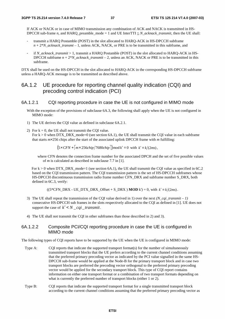
ETSI
ETSI TS 125 214 V7.4.0 (2007-03) 373GPP TS 25.214 version 7.4.0 Release 7
If ACK or NACK or in case of MIMO transmission any combination of ACK and NACK is transmitted in HS-DPCCH sub-frame n, and HARQ_preamble_mode = 1 and UE InterTTI ≤ N_acknack_transmit, then the UE shall:
- transmit a HARQ Postamble (POST) in the slot allocated to HARQ-ACK in HS-DPCCH subframe n + 2*N_acknack_transmt – 1, unless ACK, NACK, or PRE is to be transmitted in this subframe, and
- if N_acknack_transmit > 1, transmit a HARQ Postamble (POST) in the slot allocated to HARQ-ACK in HS-DPCCH subframe n + 2*N_acknack_transmit – 2, unless an ACK, NACK or PRE is to be transmitted in this subframe.
DTX shall be used on the HS-DPCCH in the slot allocated to HARQ-ACK in the corresponding HS-DPCCH subframe unless a HARQ-ACK message is to be transmitted as described above.
6A.1.2 UE procedure for reporting channel quality indication (CQI) and precoding control indication (PCI)
6A.1.2.1 CQI reporting procedure in case the UE is not configured in MIMO mode
With the exception of the provisions of subclause 6A.3, the following shall apply when the UE is not configured in MIMO mode:
1) The UE derives the CQI value as defined in subclause 6A.2.1.
2) For k = 0, the UE shall not transmit the CQI value. For k > 0 when DTX_DRX_mode=0 (see section 6A.1), the UE shall transmit the CQI value in each subframe that starts m×256 chips after the start of the associated uplink DPCCH frame with m fulfilling:
( ) 0mod76802565 =′×+× kchipchipmCFN with )2( mskk =′ ,
where CFN denotes the connection frame number for the associated DPCH and the set of five possible values of m is calculated as described in subclause 7.7 in [1].
For k > 0 when DTX_DRX_mode=1 (see section 6A.1), the UE shall transmit the CQI value as specified in 6C.2 based on the CQI transmission pattern. The CQI transmission pattern is the set of HS-DPCCH subframes whose HS-DPCCH discontinuous transmission radio frame number CFN_DRX and subframe number S_DRX, both defined in 6C.3, verify:
((5*CFN_DRX - UE_DTX_DRX_Offset + S_DRX ) MOD k') = 0, with )2( mskk =′ .
3) The UE shall repeat the transmission of the CQI value derived in 1) over the next (N_cqi_transmit – 1) consecutive HS-DPCCH sub frames in the slots respectively allocated to the CQI as defined in [1]. UE does not support the case of transmitcqiNk __<′ .
4) The UE shall not transmit the CQI in other subframes than those described in 2) and 3).
6A.1.2.2 Composite PCI/CQI reporting procedure in case the UE is configured in MIMO mode
The following types of CQI reports have to be supported by the UE when the UE is configured in MIMO mode:
Type A: CQI reports that indicate the supported transport format(s) for the number of simultaneously transmitted transport blocks that the UE prefers according to the current channel conditions assuming that the preferred primary precoding vector as indicated by the PCI value signalled in the same HS-DPCCH sub-frame would be applied at the Node-B for the primary transport block and in case two transport blocks are preferred the precoding vector orthogonal to the preferred primary precoding vector would be applied for the secondary transport block. This type of CQI report contains information on either one transport format or a combination of two transport formats depending on what is currently the preferred number of transport blocks (either 1 or 2).
Type B: CQI reports that indicate the supported transport format for a single transmitted transport block according to the current channel conditions assuming that the preferred primary precoding vector as
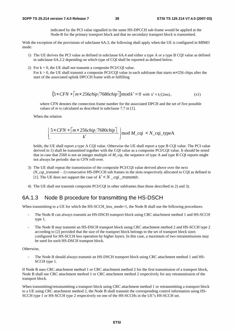
ETSI
ETSI TS 125 214 V7.4.0 (2007-03) 383GPP TS 25.214 version 7.4.0 Release 7
indicated by the PCI value signalled in the same HS-DPCCH sub-frame would be applied at the Node-B for the primary transport block and that no secondary transport block is transmitted.
With the exception of the provisions of subclause 6A.3, the following shall apply when the UE is configured in MIMO mode:
1) The UE derives the PCI value as defined in subclause 6A.4 and either a type A or a type B CQI value as defined in subclause 6A.2.2 depending on which type of CQI shall be reported as defined below.
2) For k = 0, the UE shall not transmit a composite PCI/CQI value. For k > 0, the UE shall transmit a composite PCI/CQI value in each subframe that starts m×256 chips after the start of the associated uplink DPCCH frame with m fulfilling
( ) 0mod76802565 =′×+× kchipchipmCFN with )2( mskk =′ , (x1)
where CFN denotes the connection frame number for the associated DPCH and the set of five possible values of m is calculated as described in subclause 7.7 in [1].
When the relation
_cqi_typeA _cqimod76802565
NMk
chipchipmCFN <
′
×+×
holds, the UE shall report a type A CQI value. Otherwise the UE shall report a type B CQI value. The PCI value derived in 1) shall be transmitted together with the CQI value as a composite PCI/CQI value. It should be noted that in case that 2560 is not an integer multiple of M_cqi, the sequence of type A and type B CQI reports might not always be periodic due to CFN roll-over.
3) The UE shall repeat the transmission of the composite PCI/CQI value derived above over the next (N_cqi_transmit – 1) consecutive HS-DPCCH sub frames in the slots respectively allocated to CQI as defined in [1]. The UE does not support the case of transmitcqiNk __<′ .
4) The UE shall not transmit composite PCI/CQI in other subframes than those described in 2) and 3).
6A.1.3 Node B procedure for transmitting the HS-DSCH
When transmitting to a UE for which the HS-SCCH_less_mode=1, the Node B shall use the following procedures:
- The Node B can always transmit an HS-DSCH transport block using CRC attachment method 1 and HS-SCCH type 1.
- The Node B may transmit an HS-DSCH transport block using CRC attachment method 2 and HS-SCCH type 2 according to [2] provided that the size of the transport block belongs to the set of transport block sizes configured for HS-SCCH less operation by higher layers. In this case, a maximum of two retransmissions may be used for each HS-DSCH transport block.
Otherwise,
- The Node B should always transmit an HS-DSCH transport block using CRC attachment method 1 and HS-SCCH type 1.
If Node B uses CRC attachment method 1 or CRC attachment method 2 for the first transmission of a transport block, Node B shall use CRC attachment method 1 or CRC attachment method 2 respectively for any retransmission of the transport block.
When transmitting/retransmitting a transport block using CRC attachment method 1 or retransmitting a transport block to a UE using CRC attachment method 2, the Node B shall transmit the corresponding control information using HS-SCCH type 1 or HS-SCCH type 2 respectively on one of the HS-SCCHs in the UE"s HS-SCCH set.
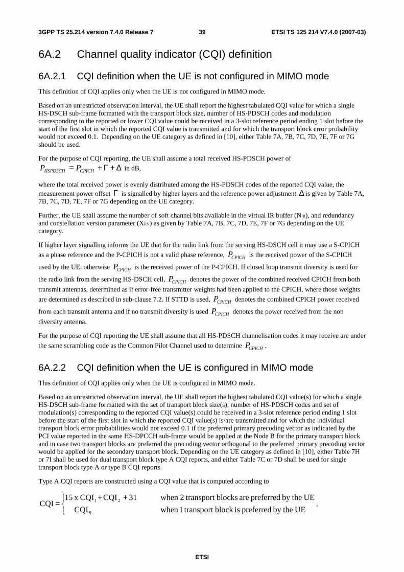
ETSI
ETSI TS 125 214 V7.4.0 (2007-03) 393GPP TS 25.214 version 7.4.0 Release 7
6A.2 Channel quality indicator (CQI) definition
6A.2.1 CQI definition when the UE is not configured in MIMO mode
This definition of CQI applies only when the UE is not configured in MIMO mode.
Based on an unrestricted observation interval, the UE shall report the highest tabulated CQI value for which a single HS-DSCH sub-frame formatted with the transport block size, number of HS-PDSCH codes and modulation corresponding to the reported or lower CQI value could be received in a 3-slot reference period ending 1 slot before the start of the first slot in which the reported CQI value is transmitted and for which the transport block error probability would not exceed 0.1. Depending on the UE category as defined in [10], either Table 7A, 7B, 7C, 7D, 7E, 7F or 7G should be used.
For the purpose of CQI reporting, the UE shall assume a total received HS-PDSCH power of
∆+Γ+= CPICHHSPDSCH PP in dB,
where the total received power is evenly distributed among the HS-PDSCH codes of the reported CQI value, the measurement power offset Γ is signalled by higher layers and the reference power adjustment ∆ is given by Table 7A, 7B, 7C, 7D, 7E, 7F or 7G depending on the UE category.
Further, the UE shall assume the number of soft channel bits available in the virtual IR buffer (NIR), and redundancy and constellation version parameter (XRV) as given by Table 7A, 7B, 7C, 7D, 7E, 7F or 7G depending on the UE category.
If higher layer signalling informs the UE that for the radio link from the serving HS-DSCH cell it may use a S-CPICH
as a phase reference and the P-CPICH is not a valid phase reference, CPICHP is the received power of the S-CPICH
used by the UE, otherwise CPICHP is the received power of the P-CPICH. If closed loop transmit diversity is used for
the radio link from the serving HS-DSCH cell, CPICHP denotes the power of the combined received CPICH from both
transmit antennas, determined as if error-free transmitter weights had been applied to the CPICH, where those weights
are determined as described in sub-clause 7.2. If STTD is used, CPICHP denotes the combined CPICH power received
from each transmit antenna and if no transmit diversity is used CPICHP denotes the power received from the non
diversity antenna.
For the purpose of CQI reporting the UE shall assume that all HS-PDSCH channelisation codes it may receive are under
the same scrambling code as the Common Pilot Channel used to determine CPICHP .
6A.2.2 CQI definition when the UE is configured in MIMO mode
This definition of CQI applies only when the UE is configured in MIMO mode.
Based on an unrestricted observation interval, the UE shall report the highest tabulated CQI value(s) for which a single HS-DSCH sub-frame formatted with the set of transport block size(s), number of HS-PDSCH codes and set of modulation(s) corresponding to the reported CQI value(s) could be received in a 3-slot reference period ending 1 slot before the start of the first slot in which the reported CQI value(s) is/are transmitted and for which the individual transport block error probabilities would not exceed 0.1 if the preferred primary precoding vector as indicated by the PCI value reported in the same HS-DPCCH sub-frame would be applied at the Node B for the primary transport block and in case two transport blocks are preferred the precoding vector orthogonal to the preferred primary precoding vector would be applied for the secondary transport block. Depending on the UE category as defined in [10], either Table 7H or 7I shall be used for dual transport block type A CQI reports, and either Table 7C or 7D shall be used for single transport block type A or type B CQI reports.
Type A CQI reports are constructed using a CQI value that is computed according to
++
= UEby the preferred isblock transport1when CQI
UEby the preferred are blocks transport2when 31CQICQI x 15 CQI
S
21,
ETSI
ETSI TS 125 214 V7.4.0 (2007-03) 403GPP TS 25.214 version 7.4.0 Release 7
where CQI1 indicates the supported transport format according to Table 7H or 7I for the transport block that could be received with the specified block error probability if it was transmitted with the preferred primary precoding vector and CQI2 indicates the supported transport format according to Table 7H or 7I for the transport block that could be received with the specified block error probability if it was transmitted with the precoding vector orthogonal to the preferred primary precoding vector. CQIS indicates the supported transport format according to Table 7C or 7D for the transport block that could be received with the specified block error probability if it was transmitted with the preferred primary precoding vector.
Type B CQI reports are constructed using the CQI value of the supported transport format according to Table 7C or 7D for the transport block that could be received with the specified block error probability if it was transmitted with the preferred primary precoding vector.
For the purpose of CQI reporting, the UE shall assume a total received HS-PDSCH power of
Γ+= CPICHHSPDSCH PP in dB,
where the total received power is assumed to be to be evenly distributed among 15 HS-PDSCH codes, and the measurement power offset Γ is signaled by higher layers.
If a CQI for a single transport block is reported, the parameter ∆ that is given by Table 7C or 7D depending on the UE category indicates a reference power adjustment for the Node B transmit power on the indicated HS-PDSCH(s). If a CQI for two transport blocks is reported, the parameter ∆ that is given by Table 7H or 7I depending on the UE category indicates by how much the equivalent AWGN symbol SINR for a specific transport block would be different from the one required to meet the predicted BLER performance.
When deriving the CQI value, the UE assumes that the Node B would be using a uniform power allocation across 15 OVSF codes. In case the UE reports a CQI for two transport blocks, it is assumed by the UE that the Node B uses an equal power per OVSF code for both of the two transport blocks. If the Node B does not transmit equal power per OVSF code, it should not assume that the reported transport block sizes can be received with the specified block error probabilities.
The measurement power offset Γ that is signalled by higher layers should be adjusted by the Node B such that it reflects the power that would be available for HS-PDSCH transmission relative to the combined transmit power of the set of CPICH(s) that shall be used for HS-PDSCH demodulation in case the Node B would have 15 OVSF codes available for HS-PDSCH transmission such that it results in the same power per OVSF code as the current power and code resources actually available for HS-PDSCH transmission at the Node B would allow.
Further, the UE shall assume the number of soft channel bits available in the virtual IR buffer (NIR), and redundancy and constellation version parameter (Xrv, Xrvpb, or Xrvsb) as given by Table 7C, 7D, 7F or 7G depending on the UE category and on the CQI report type.
If a single transport block is preferred, CPICHP denotes the power of the combined received set of CPICH(s) that shall
be used for HS-PDSCH demodulation when the UE is configured in MIMO mode, determined as if the preferred primary precoding vector had been applied to that set of CPICH(s).
If two transport blocks are preferred, CPICHP denotes the sum of the powers received from the set of CPICH(s) that
shall be used for HS-PDSCH demodulation when the UE is configured in MIMO mode.
For the purpose of CQI reporting the UE shall assume that all HS-PDSCH channelisation codes it may receive are under
the same scrambling code as the set of CPICH(s) used to determine CPICHP .
6A.2.3 CQI tables
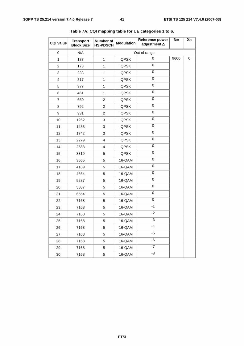
ETSI
ETSI TS 125 214 V7.4.0 (2007-03) 413GPP TS 25.214 version 7.4.0 Release 7
Table 7A: CQI mapping table for UE categories 1 to 6.
CQI value Transport Block Size
Number of HS-PDSCH Modulation
Reference power adjustment ∆∆∆∆
NIR Xrv
0 N/A Out of range
1 137 1 QPSK 0
2 173 1 QPSK 0
3 233 1 QPSK 0
4 317 1 QPSK 0
5 377 1 QPSK 0
6 461 1 QPSK 0
7 650 2 QPSK 0
8 792 2 QPSK 0
9 931 2 QPSK 0
10 1262 3 QPSK 0
11 1483 3 QPSK 0
12 1742 3 QPSK 0
13 2279 4 QPSK 0
14 2583 4 QPSK 0
15 3319 5 QPSK 0
16 3565 5 16-QAM 0
17 4189 5 16-QAM 0
18 4664 5 16-QAM 0
19 5287 5 16-QAM 0
20 5887 5 16-QAM 0
21 6554 5 16-QAM 0
22 7168 5 16-QAM 0
23 7168 5 16-QAM -1
24 7168 5 16-QAM -2
25 7168 5 16-QAM -3
26 7168 5 16-QAM -4
27 7168 5 16-QAM -5
28 7168 5 16-QAM -6
29 7168 5 16-QAM -7
30 7168 5 16-QAM -8
9600 0

ETSI
ETSI TS 125 214 V7.4.0 (2007-03) 423GPP TS 25.214 version 7.4.0 Release 7
Table 7B: CQI mapping table for UE categories 7 and 8.
CQI value Transport Block Size
Number of HS-PDSCH Modulation
Reference power adjustment ∆∆∆∆
NIR Xrv
0 N/A Out of range
1 137 1 QPSK 0
2 173 1 QPSK 0
3 233 1 QPSK 0
4 317 1 QPSK 0
5 377 1 QPSK 0
6 461 1 QPSK 0
7 650 2 QPSK 0
8 792 2 QPSK 0
9 931 2 QPSK 0
10 1262 3 QPSK 0
11 1483 3 QPSK 0
12 1742 3 QPSK 0
13 2279 4 QPSK 0
14 2583 4 QPSK 0
15 3319 5 QPSK 0
16 3565 5 16-QAM 0
17 4189 5 16-QAM 0
18 4664 5 16-QAM 0
19 5287 5 16-QAM 0
20 5887 5 16-QAM 0
21 6554 5 16-QAM 0
22 7168 5 16-QAM 0
23 9719 7 16-QAM 0
24 11418 8 16-QAM 0
25 14411 10 16-QAM 0
26 14411 10 16-QAM -1
27 14411 10 16-QAM -2
28 14411 10 16-QAM -3
29 14411 10 16-QAM -4
30 14411 10 16-QAM -5
19200 0
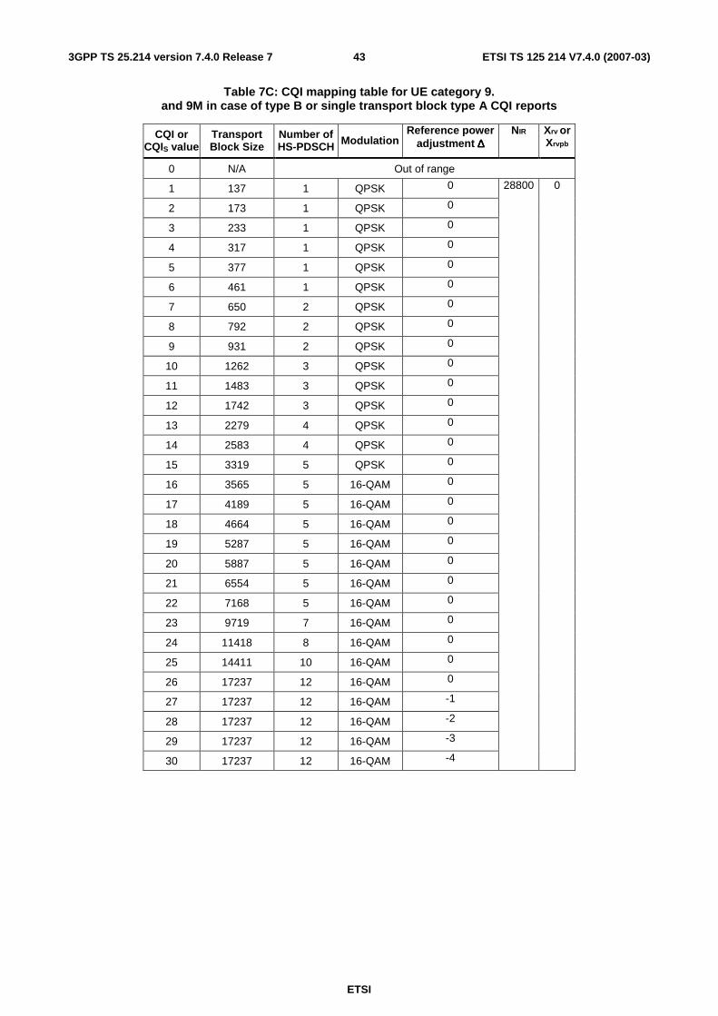
ETSI
ETSI TS 125 214 V7.4.0 (2007-03) 433GPP TS 25.214 version 7.4.0 Release 7
Table 7C: CQI mapping table for UE category 9. and 9M in case of type B or single transport block type A CQI reports
CQI or CQIS value
Transport Block Size
Number of HS-PDSCH Modulation
Reference power adjustment ∆∆∆∆
NIR Xrv or
Xrvpb
0 N/A Out of range
1 137 1 QPSK 0
2 173 1 QPSK 0
3 233 1 QPSK 0
4 317 1 QPSK 0
5 377 1 QPSK 0
6 461 1 QPSK 0
7 650 2 QPSK 0
8 792 2 QPSK 0
9 931 2 QPSK 0
10 1262 3 QPSK 0
11 1483 3 QPSK 0
12 1742 3 QPSK 0
13 2279 4 QPSK 0
14 2583 4 QPSK 0
15 3319 5 QPSK 0
16 3565 5 16-QAM 0
17 4189 5 16-QAM 0
18 4664 5 16-QAM 0
19 5287 5 16-QAM 0
20 5887 5 16-QAM 0
21 6554 5 16-QAM 0
22 7168 5 16-QAM 0
23 9719 7 16-QAM 0
24 11418 8 16-QAM 0
25 14411 10 16-QAM 0
26 17237 12 16-QAM 0
27 17237 12 16-QAM -1
28 17237 12 16-QAM -2
29 17237 12 16-QAM -3
30 17237 12 16-QAM -4
28800 0

ETSI
ETSI TS 125 214 V7.4.0 (2007-03) 443GPP TS 25.214 version 7.4.0 Release 7
Table 7D: CQI mapping table for UE category 10, and 10M in case of type B or single transport block type A CQI reports.
CQI or CQIS value
Transport Block Size
Number of HS-PDSCH Modulation
Reference power adjustment ∆∆∆∆
NIR Xrv or
Xrvpb
0 N/A Out of range
1 137 1 QPSK 0
2 173 1 QPSK 0
3 233 1 QPSK 0
4 317 1 QPSK 0
5 377 1 QPSK 0
6 461 1 QPSK 0
7 650 2 QPSK 0
8 792 2 QPSK 0
9 931 2 QPSK 0
10 1262 3 QPSK 0
11 1483 3 QPSK 0
12 1742 3 QPSK 0
13 2279 4 QPSK 0
14 2583 4 QPSK 0
15 3319 5 QPSK 0
16 3565 5 16-QAM 0
17 4189 5 16-QAM 0
18 4664 5 16-QAM 0
19 5287 5 16-QAM 0
20 5887 5 16-QAM 0
21 6554 5 16-QAM 0
22 7168 5 16-QAM 0
23 9719 7 16-QAM 0
24 11418 8 16-QAM 0
25 14411 10 16-QAM 0
26 17237 12 16-QAM 0
27 21754 15 16-QAM 0
28 23370 15 16-QAM 0
29 24222 15 16-QAM 0
30 25558 15 16-QAM 0
28800 0
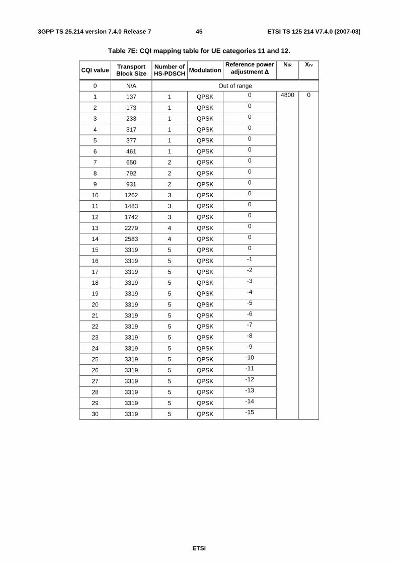
ETSI
ETSI TS 125 214 V7.4.0 (2007-03) 453GPP TS 25.214 version 7.4.0 Release 7
Table 7E: CQI mapping table for UE categories 11 and 12.
CQI value Transport Block Size
Number of HS-PDSCH Modulation
Reference power adjustment ∆∆∆∆
NIR Xrv
0 N/A Out of range
1 137 1 QPSK 0
2 173 1 QPSK 0
3 233 1 QPSK 0
4 317 1 QPSK 0
5 377 1 QPSK 0
6 461 1 QPSK 0
7 650 2 QPSK 0
8 792 2 QPSK 0
9 931 2 QPSK 0
10 1262 3 QPSK 0
11 1483 3 QPSK 0
12 1742 3 QPSK 0
13 2279 4 QPSK 0
14 2583 4 QPSK 0
15 3319 5 QPSK 0
16 3319 5 QPSK -1
17 3319 5 QPSK -2
18 3319 5 QPSK -3
19 3319 5 QPSK -4
20 3319 5 QPSK -5
21 3319 5 QPSK -6
22 3319 5 QPSK -7
23 3319 5 QPSK -8
24 3319 5 QPSK -9
25 3319 5 QPSK -10
26 3319 5 QPSK -11
27 3319 5 QPSK -12
28 3319 5 QPSK -13
29 3319 5 QPSK -14
30 3319 5 QPSK -15
4800 0
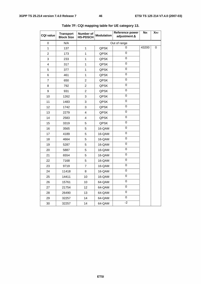
ETSI
ETSI TS 125 214 V7.4.0 (2007-03) 463GPP TS 25.214 version 7.4.0 Release 7
Table 7F: CQI mapping table for UE category 13.
CQI value Transport Block Size
Number of HS-PDSCH Modulation
Reference power adjustment ∆∆∆∆
NIR XRV
0 N/A Out of range
1 137 1 QPSK 0
2 173 1 QPSK 0
3 233 1 QPSK 0
4 317 1 QPSK 0
5 377 1 QPSK 0
6 461 1 QPSK 0
7 650 2 QPSK 0
8 792 2 QPSK 0
9 931 2 QPSK 0
10 1262 3 QPSK 0
11 1483 3 QPSK 0
12 1742 3 QPSK 0
13 2279 4 QPSK 0
14 2583 4 QPSK 0
15 3319 5 QPSK 0
16 3565 5 16-QAM 0
17 4189 5 16-QAM 0
18 4664 5 16-QAM 0
19 5287 5 16-QAM 0
20 5887 5 16-QAM 0
21 6554 5 16-QAM 0
22 7168 5 16-QAM 0
23 9719 7 16-QAM 0
24 11418 8 16-QAM 0
25 14411 10 16-QAM 0
26 15761 10 64-QAM 0
27 21754 12 64-QAM 0
28 26490 13 64-QAM 0
29 32257 14 64-QAM 0
30 32257 14 64-QAM -2
43200 0

ETSI
ETSI TS 125 214 V7.4.0 (2007-03) 473GPP TS 25.214 version 7.4.0 Release 7
Table 7G: CQI mapping table for UE category 14.
CQI value Transport Block Size
Number of HS-PDSCH Modulation
Reference power adjustment ∆∆∆∆
NIR XRV
0 N/A Out of range
1 137 1 QPSK 0
2 173 1 QPSK 0
3 233 1 QPSK 0
4 317 1 QPSK 0
5 377 1 QPSK 0
6 461 1 QPSK 0
7 650 2 QPSK 0
8 792 2 QPSK 0
9 931 2 QPSK 0
10 1262 3 QPSK 0
11 1483 3 QPSK 0
12 1742 3 QPSK 0
13 2279 4 QPSK 0
14 2583 4 QPSK 0
15 3319 5 QPSK 0
16 3565 5 16-QAM 0
17 4189 5 16-QAM 0
18 4664 5 16-QAM 0
19 5287 5 16-QAM 0
20 5887 5 16-QAM 0
21 6554 5 16-QAM 0
22 7168 5 16-QAM 0
23 9719 7 16-QAM 0
24 11418 8 16-QAM 0
25 14411 10 16-QAM 0
26 15761 10 64-QAM 0
27 21754 12 64-QAM 0
28 26490 13 64-QAM 0
29 32257 14 64-QAM 0
30 38582 15 64-QAM 0
43200 0
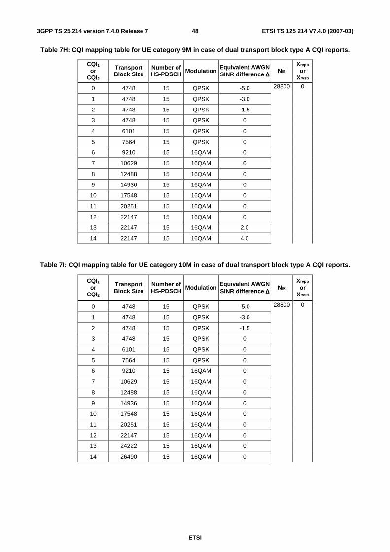
ETSI
ETSI TS 125 214 V7.4.0 (2007-03) 483GPP TS 25.214 version 7.4.0 Release 7
Table 7H: CQI mapping table for UE category 9M in case of dual transport block type A CQI reports.
CQI1 or
CQI2
Transport Block Size
Number of HS-PDSCH Modulation
Equivalent AWGN SINR difference ∆∆∆∆
NIR Xrvpb
or Xrvsb
0 4748 15 QPSK -5.0
1 4748 15 QPSK -3.0
2 4748 15 QPSK -1.5
3 4748 15 QPSK 0
4 6101 15 QPSK 0
5 7564 15 QPSK 0
6 9210 15 16QAM 0
7 10629 15 16QAM 0
8 12488 15 16QAM 0
9 14936 15 16QAM 0
10 17548 15 16QAM 0
11 20251 15 16QAM 0
12 22147 15 16QAM 0
13 22147 15 16QAM 2.0
14 22147 15 16QAM 4.0
28800 0
Table 7I: CQI mapping table for UE category 10M in case of dual transport block type A CQI reports.
CQI1 or
CQI2
Transport Block Size
Number of HS-PDSCH Modulation
Equivalent AWGN SINR difference ∆∆∆∆
NIR Xrvpb
or Xrvsb
0 4748 15 QPSK -5.0
1 4748 15 QPSK -3.0
2 4748 15 QPSK -1.5
3 4748 15 QPSK 0
4 6101 15 QPSK 0
5 7564 15 QPSK 0
6 9210 15 16QAM 0
7 10629 15 16QAM 0
8 12488 15 16QAM 0
9 14936 15 16QAM 0
10 17548 15 16QAM 0
11 20251 15 16QAM 0
12 22147 15 16QAM 0
13 24222 15 16QAM 0
14 26490 15 16QAM 0
28800 0
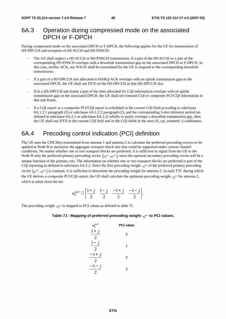
ETSI
ETSI TS 125 214 V7.4.0 (2007-03) 493GPP TS 25.214 version 7.4.0 Release 7
6A.3 Operation during compressed mode on the associated DPCH or F-DPCH
During compressed mode on the associated DPCH or F-DPCH, the following applies for the UE for transmission of HS-DPCCH and reception of HS-SCCH and HS-PDSCH:
- The UE shall neglect a HS-SCCH or HS-PDSCH transmission, if a part of the HS-SCCH or a part of the corresponding HS-PDSCH overlaps with a downlink transmission gap on the associated DPCH or F-DPCH. In this case, neither ACK, nor NACK shall be transmitted by the UE to respond to the corresponding downlink transmission.
- If a part of a HS-DPCCH slot allocated to HARQ-ACK overlaps with an uplink transmission gap on the associated DPCH, the UE shall use DTX on the HS-DPCCH in that HS-DPCCH slot.
- If in a HS-DPCCH sub-frame a part of the slots allocated for CQI information overlaps with an uplink transmission gap on the associated DPCH, the UE shall not transmit CQI or composite PCI/CQI information in that sub-frame.
- If a CQI report or a composite PCI/CQI report is scheduled in the current CQI field according to subclause 6A.1.2.1 paragraph (2) or subclause 6A.1.2.2 paragraph (2), and the corresponding 3-slot reference period (as defined in subclause 6A.2.1 or subclause 6A.2.2) wholly or partly overlaps a downlink transmission gap, then the UE shall use DTX in the current CQI field and in the CQI fields in the next (N_cqi_transmit–1) subframes.
6A.4 Precoding control indication (PCI) definition The UE uses the CPICH(s) transmitted from antenna 1 and antenna 2 to calculate the preferred precoding vectors to be applied at Node B to maximise the aggregate transport block size that could be supported under current channel conditions. No matter whether one or two transport blocks are preferred, it is sufficient to signal from the UE to the Node B only the preferred primary precoding vector ( )pref
2pref1 , ww , since the optional secondary precoding vector will be a
unique function of the primary one. The information on whether one or two transport blocks are preferred is part of the CQI reporting as defined in subclause 6A.2.2. Since the first precoding weight pref
1w of the preferred primary precoding
vector ( )pref2
pref1 , ww is constant, it is sufficient to determine the precoding weight for antenna 2. In each TTI during which
the UE derives a composite PCI/CQI report, the UE shall calculate the optimum precoding weight pref2w for antenna 2 ,
which is taken from the set:
−−+−−+∈
2
1
2
1
2
1
2
1pref2
jjjjw .
The precoding weight pref2w is mapped to PCI values as defined in table 7J.
Table 7J : Mapping of preferred precoding weight pref2w to PCI values.
pref2w PCI value
2
1 j+ 0
2
1 j− 1
2
1 j+− 2
2
1 j−− 3
ETSI
ETSI TS 125 214 V7.4.0 (2007-03) 503GPP TS 25.214 version 7.4.0 Release 7
6B E-DCH related procedures The following physical layer parameters are signalled to the UE from higher layers:
1) E-HICH set to be monitored
2) E-RGCH set to be monitored
6B.1 ACK/NACK detection The physical layer in the UE shall detect ACK or NACK within the E-HICH set that is monitored by the UE in the subframes where ACK/NACK is transmitted by the UTRAN and deliver the ACK/NACK to the higher layers as follows:
- When a UE is not in soft handover, an ACK shall be delivered to the higher layers if a reliable ACK is detected by the physical layer in the UE, else a NACK shall be delivered to the higher layers.
- When a UE is in soft handover, multiple ACK/NACKs may be received in an E-DCH TTI from different cells in the active set. In some cases, the UE has the knowledge that some of the transmitted ACK/NACKs are the same. This is the case when the radio links are in the same radio link set. For these cases, ACK/NACKs from the same radio link set shall be soft combined into one ACK/NACK information and delivered to higher layers. If a radio link set contains only one radio link, the detection shall be done as specified above for the case where the UE is not in soft handover. For each radio link set containing multiple radio links, an ACK shall be delivered to the higher layers if a reliable ACK is detected by the physical layer in the UE after soft combining, else a NACK shall be delivered to the higher layers.
6B.2 Relative grants detection The physical layer in the UE shall detect relative grants within the E-RGCH set that is monitored by the UE and deliver the relative grants to the higher layers as follows:
- When a UE is not in soft handover, an UP shall be delivered to the higher layers if a reliable UP is detected by the physical layer in the UE, else a DOWN shall be delivered to the higher layers if a reliable DOWN is detected by the UE, else a HOLD shall be delivered to the higher layers.
- When a UE is in soft handover, multiple relative grants may be received in an E-DCH TTI from different cells in the E-DCH active set. The UE shall handle the E-RGCH received from these cells as follows:
o If the E-DCH serving radio link set contains only one radio link, the detection shall be done as specified above for the case where the UE is not in soft handover. If the E-DCH serving radio link set contains more than one radio link, the relative grants from the E-DCH serving radio link set are the same and shall be soft combined into one single relative grant information; an UP shall be delivered to the higher layers if a reliable UP is detected by the physical layer in the UE after soft combining, else a DOWN shall be delivered to the higher layers if a reliable DOWN is detected by the UE after soft combining, else a HOLD shall be delivered to the higher layers.
o Furthermore, for each relative grant received from a radio link which does not belong to the E-DCH serving radio link set, a DOWN shall be delivered to the higher layers if a reliable DOWN is detected by the UE, else a HOLD shall be delivered to the higher layers. The UE shall not soft combine relative grants received from radio links which do not belong to the E-DCH serving radio link set.
6B.3 E-DCH control timing In sub-clauses 6B.3.1 and 6B.3.2 the word "first" refers to the earliest point in time.
6B.3.1 10 ms E-DCH TTI
For each cell in the E-DCH active set, the UE shall associate the control data received in the E-HICH frame associated with SFN i to the data transmitted in the E-DPDCH frame associated with SFN i-3.
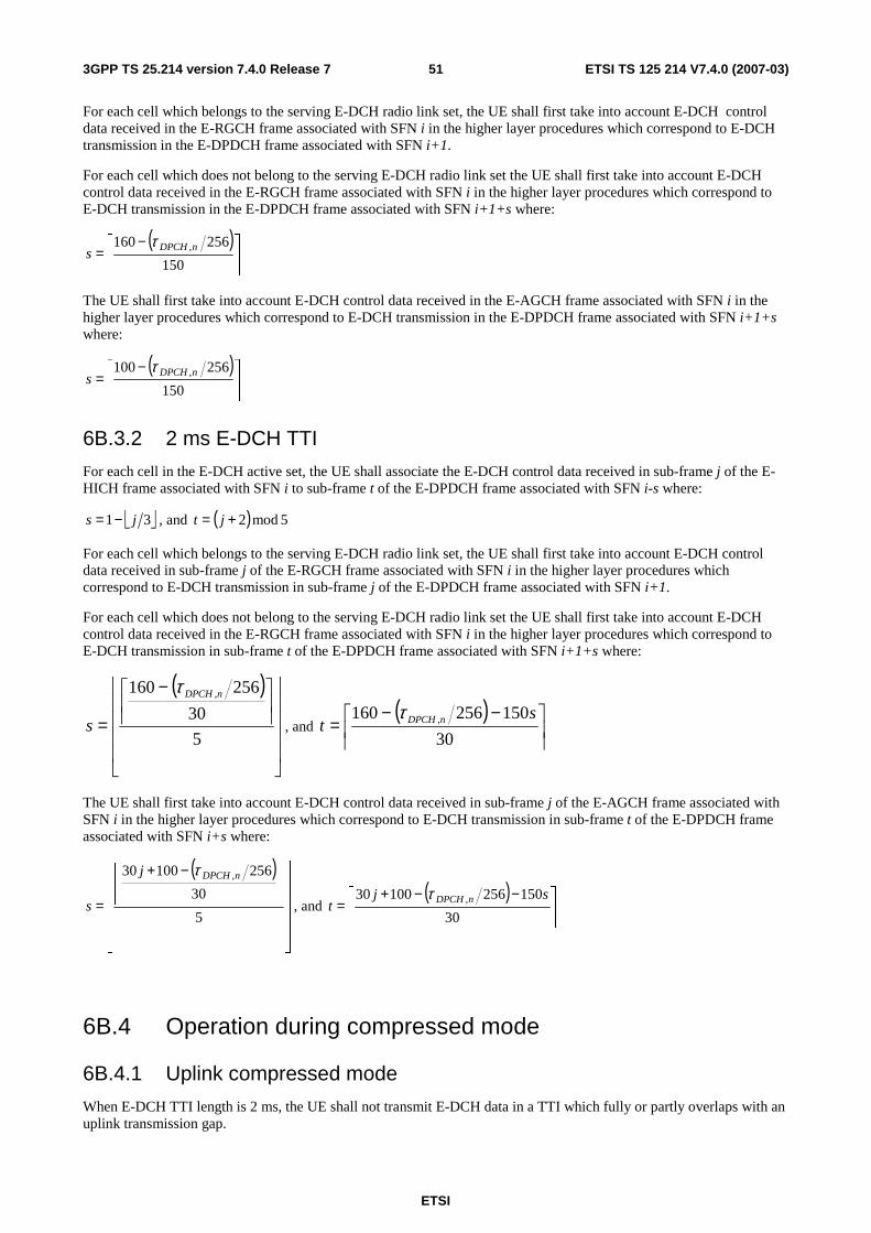
ETSI
ETSI TS 125 214 V7.4.0 (2007-03) 513GPP TS 25.214 version 7.4.0 Release 7
For each cell which belongs to the serving E-DCH radio link set, the UE shall first take into account E-DCH control data received in the E-RGCH frame associated with SFN i in the higher layer procedures which correspond to E-DCH transmission in the E-DPDCH frame associated with SFN i+1.
For each cell which does not belong to the serving E-DCH radio link set the UE shall first take into account E-DCH control data received in the E-RGCH frame associated with SFN i in the higher layer procedures which correspond to E-DCH transmission in the E-DPDCH frame associated with SFN i+1+s where:
( )
−=
150
256160 ,nDPCHs
τ
The UE shall first take into account E-DCH control data received in the E-AGCH frame associated with SFN i in the higher layer procedures which correspond to E-DCH transmission in the E-DPDCH frame associated with SFN i+1+s where:
( )
−=
150
256100 ,nDPCHs
τ
6B.3.2 2 ms E-DCH TTI
For each cell in the E-DCH active set, the UE shall associate the E-DCH control data received in sub-frame j of the E-HICH frame associated with SFN i to sub-frame t of the E-DPDCH frame associated with SFN i-s where:
31 js −= , and ( ) 5mod2+= jt
For each cell which belongs to the serving E-DCH radio link set, the UE shall first take into account E-DCH control data received in sub-frame j of the E-RGCH frame associated with SFN i in the higher layer procedures which correspond to E-DCH transmission in sub-frame j of the E-DPDCH frame associated with SFN i+1.
For each cell which does not belong to the serving E-DCH radio link set the UE shall first take into account E-DCH control data received in the E-RGCH frame associated with SFN i in the higher layer procedures which correspond to E-DCH transmission in sub-frame t of the E-DPDCH frame associated with SFN i+1+s where:
( )
−
=5
30
256160 ,nDPCH
s
τ
, and ( )
−−=
30
150256160 , st nDPCHτ
The UE shall first take into account E-DCH control data received in sub-frame j of the E-AGCH frame associated with SFN i in the higher layer procedures which correspond to E-DCH transmission in sub-frame t of the E-DPDCH frame associated with SFN i+s where:
( )
−+
=5
30
25610030 ,nDPCHj
s
τ
, and ( )
−−+=
30
15025610030 , sjt
nDPCHτ
6B.4 Operation during compressed mode
6B.4.1 Uplink compressed mode
When E-DCH TTI length is 2 ms, the UE shall not transmit E-DCH data in a TTI which fully or partly overlaps with an uplink transmission gap.
ETSI
ETSI TS 125 214 V7.4.0 (2007-03) 523GPP TS 25.214 version 7.4.0 Release 7
Handling of uplink compressed mode when the E-DCH TTI is 10msec is described in [2].
6B.4.2 Downlink compressed mode
The following applies for the UE for reception of E-HICH, E-RGCH and E-AGCH, during compressed mode on the DPCH or F-DPCH:
- A UE shall decode E-HICH, E-RGCH or E-AGCH transmissions to the UE using all the slots which do not overlap a downlink transmission gap.
- The UE may discard E-HICH, E-RGCH or E-AGCH slots which overlap a downlink transmission gap.
6C Discontinuous transmission and reception procedures
Whether discontinuous uplink DPCCH transmission operation or discontinuous downlink reception operation are applied is determined by the settings of UL_DTX_mode and DL_DRX_mode as follows:
UL_DTX_mode shall have the value 1 while DTX_DRX_mode=1 and discontinuous uplink DPCCH transmission is activated. Otherwise, UL_DTX_mode shall have the value 0.
Discontinuous uplink DPCCH transmission shall be activated at the time when DTX_DRX_mode is set equal to 1, and may be further deactivated or activated by layer 1 HS-SCCH orders (see section 6C.4).
DL_DRX_mode shall have the value 1 while DTX_DRX_mode=1 and UL_DTX_mode=1 and discontinuous downlink reception is activated. Otherwise, DL_DRX_mode shall have the value 0.
Discontinuous downlink reception shall be activated at the time when DTX_DRX_mode is set equal to 1, and may be further deactivated or activated by layer 1 HS-SCCH orders (see section 6C.4).
The higher layers define the discontinuous transmission and reception procedures using the following parameters:
For discontinuous UL DPCCH transmission:
CQI_DTX_TIMER: Specifies the number of subframes after an HS-DSCH reception during which the CQI reports have higher priority than the DTX pattern. This is the initial value of CQI nominal reporting timer.
UE_DTX_cycle_1: Uplink DPCCH transmission pattern length in subframes.
UE_DTX_cycle_2: Uplink DPCCH transmission pattern length in subframes.
Inactivity_Threshold_for_UE_DTX_cycle_2: Defines a number of consecutive E-DCH TTIs without an E-DCH transmission, after which the UE shall immediately move from UE_DTX_cycle_1 to using UE_DTX_cycle_2.
UE_DPCCH_burst_1: Determines the Uplink DPCCH burst length in subframes, when UE_DTX_cycle_1 is applied.
UE_DPCCH_burst_2: Determines the Uplink DPCCH burst length in subframes, when UE_DTX_cycle_2 is applied.
UE_DTX_long_preamble_length: Determines in slots the length of the preamble associated with the UE_DTX_cycle_2.
For both discontinuous UL DPCCH transmission and discontinuous downlink reception:
UE_DTX_DRX Offset: Uplink DPCCH transmission pattern and HS-SCCH reception pattern offset in subframes.
Enabling_Delay: defined in [5], ensures that the uplink DPCCH and downlink F-DPCH are transmitted continuously for Enabling_Delay radio frames after DTX_DRX_STATUS is set to 1.
For discontinuous downlink reception:
UE_DRX cycle: HS-SCCH reception pattern length in subframes.
ETSI
ETSI TS 125 214 V7.4.0 (2007-03) 533GPP TS 25.214 version 7.4.0 Release 7
Inactivity_Threshold_for_UE_DRX_cycle: Defines the number of subframes after an HS-SCCH reception or after the first slot of an HS-PDSCH reception (as defined in 6C.3) during which the UE is required to monitor the HS-SCCHs in the UE"s HS-SCCH set continuously with the exceptions of N_acknack_transmit>1 or InterTTI>1.
Inactivity_Threshold_for_UE_Grant_Monitoring: Determines the number of subframes after an E-DCH scheduled transmission during which the UE is required to monitor the full E-AGCH transmissions from the serving radio link and the full E-RGCH(s) from all the cells in the E-DCH active set.
UE_DRX_Grant_Monitoring: A Boolean which determines whether the UE is required to monitor the full E-AGCH transmissions from the serving E-DCH cell and the full E-RGCH from cells in the serving E-DCH radio link set when they overlap with the start of an HS-SCCH reception as defined in the HS-SCCH reception pattern.
6C.1 Uplink HS-DPCCH transmission When UL_DTX_mode=1 (see section 6C), the UE shall perform the following procedures:
The UE shall set the initial value of the variable CQI_DTX_Priority to 0.
Afterwards the UE sets the CQI_DTX_Priority based on the status of a "CQI nominal reporting timer" which is counting down to zero in subframes from the value CQI_DTX_TIMER which is configured by higher layers.
The setting of CQI_DTX_Priority to 1 is described in subclause 6A.1.1.
Upon the expiration of the CQI nominal reporting timer, the UE shall set CQI_DTX_Priority to 0.
CQI_DTX_Priority=0 indicates that CQI reports have lower priority than the uplink DPCCH transmission pattern. If CQI_DTX_Priority is set to 0, the UE shall transmit the Channel-Quality Indication (CQI) only if at least part of the CQI subframe in the CQI transmission pattern as defined in 6A.1.2 does not overlap with a DPCCH transmission gap of the uplink DPCCH transmission pattern as indicated in 6C.2.1.
CQI_DTX_Priority=1 indicates that CQI reports have higher priority than the uplink DPCCH transmission pattern. If CQI_DTX_Priority is set to 1, the UE shall always transmit the Channel-Quality Indication (CQI) in the CQI transmission pattern defined in 6A.1.2.
6C.2 Discontinuous uplink DPCCH transmission operation When UL_DTX_mode=1 (see section 6C) the UE shall not transmit the uplink DPCCH in a slot when all of the following conditions are met:
1. There is no HARQ-ACK transmission on HS-DPCCH as indicated in 6A.1 overlapping with the UL DPCCH slot,
2. There is no CQI transmission on HS-DPCCH as indicated in 6C.1 overlapping with the UL DPCCH slot,
3. There is no E-DCH transmission during the UL DPCCH slot,
4. The slot is in a gap in the UL DPCCH transmission pattern defined in 6C.2.1,
5. The UL DPCCH preamble or postamble defined in 6C.2.2 is not transmitted in the slot.
The procedures for the F-DPCH transmission and reception in case of discontinuous uplink DPCCH operation are defined in sub-clause 5.1.
6C.2.1 Uplink DPCCH transmission pattern
The uplink DPCCH transmission pattern and the uplink DPCCH preamble and postamble (6C.2.2) together define the discontinuous uplink DPCCH operation.
The uplink DPCCH transmission pattern is illustrated in Figure 2A for 2ms E-DCH TTI and Figure 2B for 10ms E-DCH TTI. The uplink DPCCH transmission pattern defines the minimum set of slots where the UE shall transmit the UL-DPCCH.
The uplink DPCCH transmission pattern shall be derived as follows.
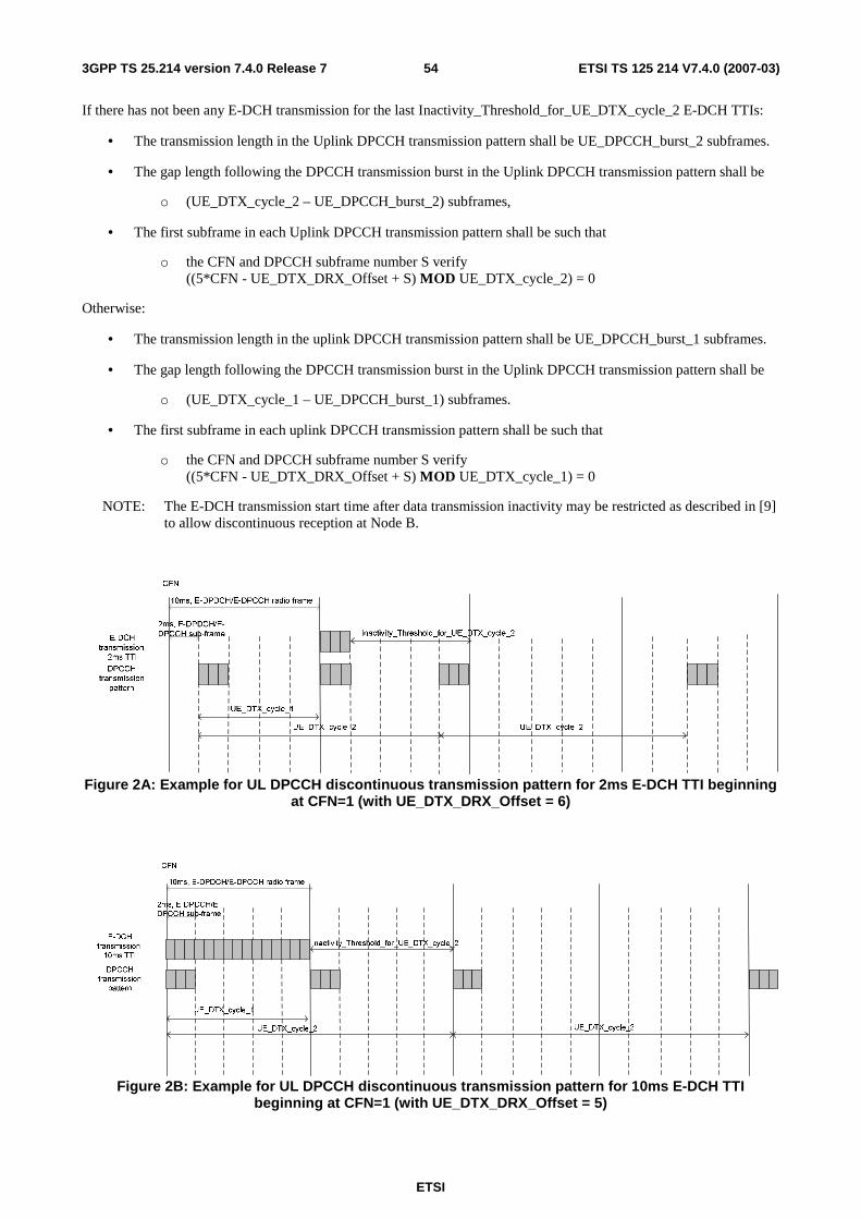
ETSI
ETSI TS 125 214 V7.4.0 (2007-03) 543GPP TS 25.214 version 7.4.0 Release 7
If there has not been any E-DCH transmission for the last Inactivity_Threshold_for_UE_DTX_cycle_2 E-DCH TTIs:
• The transmission length in the Uplink DPCCH transmission pattern shall be UE_DPCCH_burst_2 subframes.
• The gap length following the DPCCH transmission burst in the Uplink DPCCH transmission pattern shall be
o (UE_DTX_cycle_2 – UE_DPCCH_burst_2) subframes,
• The first subframe in each Uplink DPCCH transmission pattern shall be such that
o the CFN and DPCCH subframe number S verify ((5*CFN - UE_DTX_DRX_Offset + S) MOD UE_DTX_cycle_2) = 0
Otherwise:
• The transmission length in the uplink DPCCH transmission pattern shall be UE_DPCCH_burst_1 subframes.
• The gap length following the DPCCH transmission burst in the Uplink DPCCH transmission pattern shall be
o (UE_DTX_cycle_1 – UE_DPCCH_burst_1) subframes.
• The first subframe in each uplink DPCCH transmission pattern shall be such that
o the CFN and DPCCH subframe number S verify ((5*CFN - UE_DTX_DRX_Offset + S) MOD UE_DTX_cycle_1) = 0
NOTE: The E-DCH transmission start time after data transmission inactivity may be restricted as described in [9] to allow discontinuous reception at Node B.
Figure 2A: Example for UL DPCCH discontinuous transmission pattern for 2ms E-DCH TTI beginning at CFN=1 (with UE_DTX_DRX_Offset = 6)
Figure 2B: Example for UL DPCCH discontinuous transmission pattern for 10ms E-DCH TTI beginning at CFN=1 (with UE_DTX_DRX_Offset = 5)
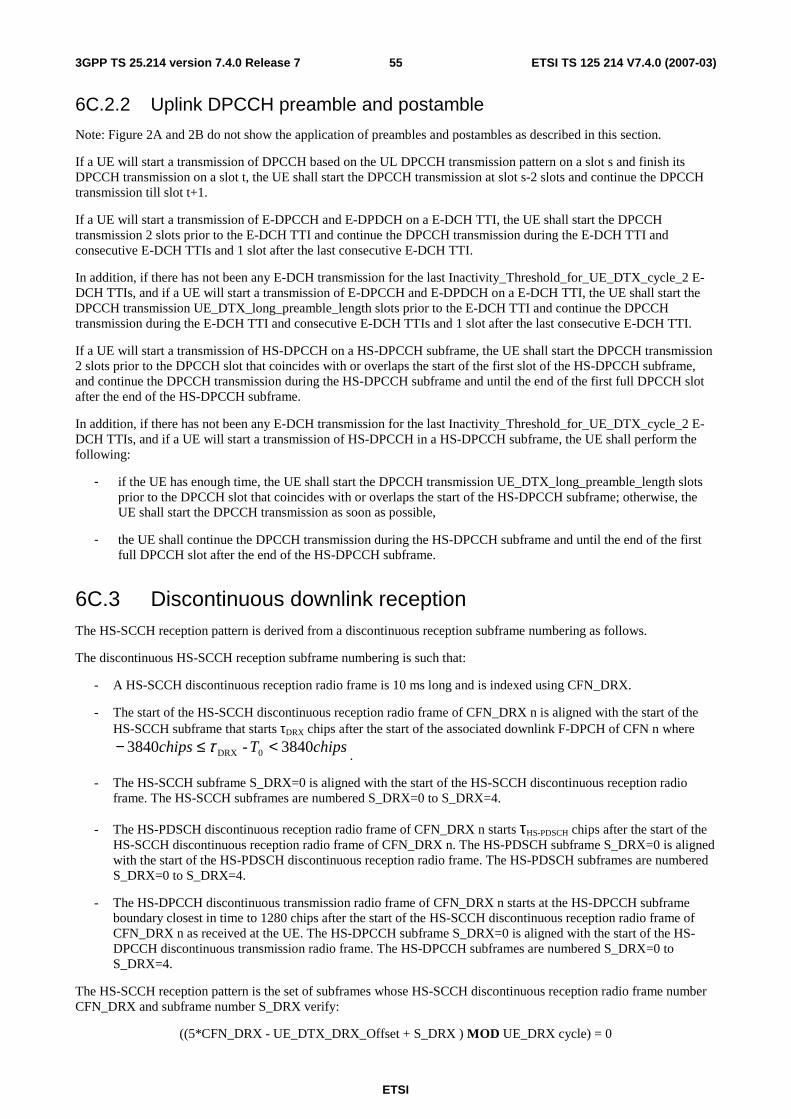
ETSI
ETSI TS 125 214 V7.4.0 (2007-03) 553GPP TS 25.214 version 7.4.0 Release 7
6C.2.2 Uplink DPCCH preamble and postamble
Note: Figure 2A and 2B do not show the application of preambles and postambles as described in this section.
If a UE will start a transmission of DPCCH based on the UL DPCCH transmission pattern on a slot s and finish its DPCCH transmission on a slot t, the UE shall start the DPCCH transmission at slot s-2 slots and continue the DPCCH transmission till slot t+1.
If a UE will start a transmission of E-DPCCH and E-DPDCH on a E-DCH TTI, the UE shall start the DPCCH transmission 2 slots prior to the E-DCH TTI and continue the DPCCH transmission during the E-DCH TTI and consecutive E-DCH TTIs and 1 slot after the last consecutive E-DCH TTI.
In addition, if there has not been any E-DCH transmission for the last Inactivity_Threshold_for_UE_DTX_cycle_2 E-DCH TTIs, and if a UE will start a transmission of E-DPCCH and E-DPDCH on a E-DCH TTI, the UE shall start the DPCCH transmission UE_DTX_long_preamble_length slots prior to the E-DCH TTI and continue the DPCCH transmission during the E-DCH TTI and consecutive E-DCH TTIs and 1 slot after the last consecutive E-DCH TTI.
If a UE will start a transmission of HS-DPCCH on a HS-DPCCH subframe, the UE shall start the DPCCH transmission 2 slots prior to the DPCCH slot that coincides with or overlaps the start of the first slot of the HS-DPCCH subframe, and continue the DPCCH transmission during the HS-DPCCH subframe and until the end of the first full DPCCH slot after the end of the HS-DPCCH subframe.
In addition, if there has not been any E-DCH transmission for the last Inactivity_Threshold_for_UE_DTX_cycle_2 E-DCH TTIs, and if a UE will start a transmission of HS-DPCCH in a HS-DPCCH subframe, the UE shall perform the following:
- if the UE has enough time, the UE shall start the DPCCH transmission UE_DTX_long_preamble_length slots prior to the DPCCH slot that coincides with or overlaps the start of the HS-DPCCH subframe; otherwise, the UE shall start the DPCCH transmission as soon as possible,
- the UE shall continue the DPCCH transmission during the HS-DPCCH subframe and until the end of the first full DPCCH slot after the end of the HS-DPCCH subframe.
6C.3 Discontinuous downlink reception The HS-SCCH reception pattern is derived from a discontinuous reception subframe numbering as follows.
The discontinuous HS-SCCH reception subframe numbering is such that:
- A HS-SCCH discontinuous reception radio frame is 10 ms long and is indexed using CFN_DRX.
- The start of the HS-SCCH discontinuous reception radio frame of CFN_DRX n is aligned with the start of the HS-SCCH subframe that starts τDRX chips after the start of the associated downlink F-DPCH of CFN n where
chipsTchips 3840- 3840 0DRX <≤− τ.
- The HS-SCCH subframe S_DRX=0 is aligned with the start of the HS-SCCH discontinuous reception radio frame. The HS-SCCH subframes are numbered S_DRX=0 to S_DRX=4.
- The HS-PDSCH discontinuous reception radio frame of CFN_DRX n starts τHS-PDSCH chips after the start of the HS-SCCH discontinuous reception radio frame of CFN_DRX n. The HS-PDSCH subframe S_DRX=0 is aligned with the start of the HS-PDSCH discontinuous reception radio frame. The HS-PDSCH subframes are numbered S_DRX=0 to S_DRX=4.
- The HS-DPCCH discontinuous transmission radio frame of CFN_DRX n starts at the HS-DPCCH subframe boundary closest in time to 1280 chips after the start of the HS-SCCH discontinuous reception radio frame of CFN_DRX n as received at the UE. The HS-DPCCH subframe S_DRX=0 is aligned with the start of the HS-DPCCH discontinuous transmission radio frame. The HS-DPCCH subframes are numbered S_DRX=0 to S_DRX=4.
The HS-SCCH reception pattern is the set of subframes whose HS-SCCH discontinuous reception radio frame number CFN_DRX and subframe number S_DRX verify:
((5*CFN_DRX - UE_DTX_DRX_Offset + S_DRX ) MOD UE_DRX cycle) = 0
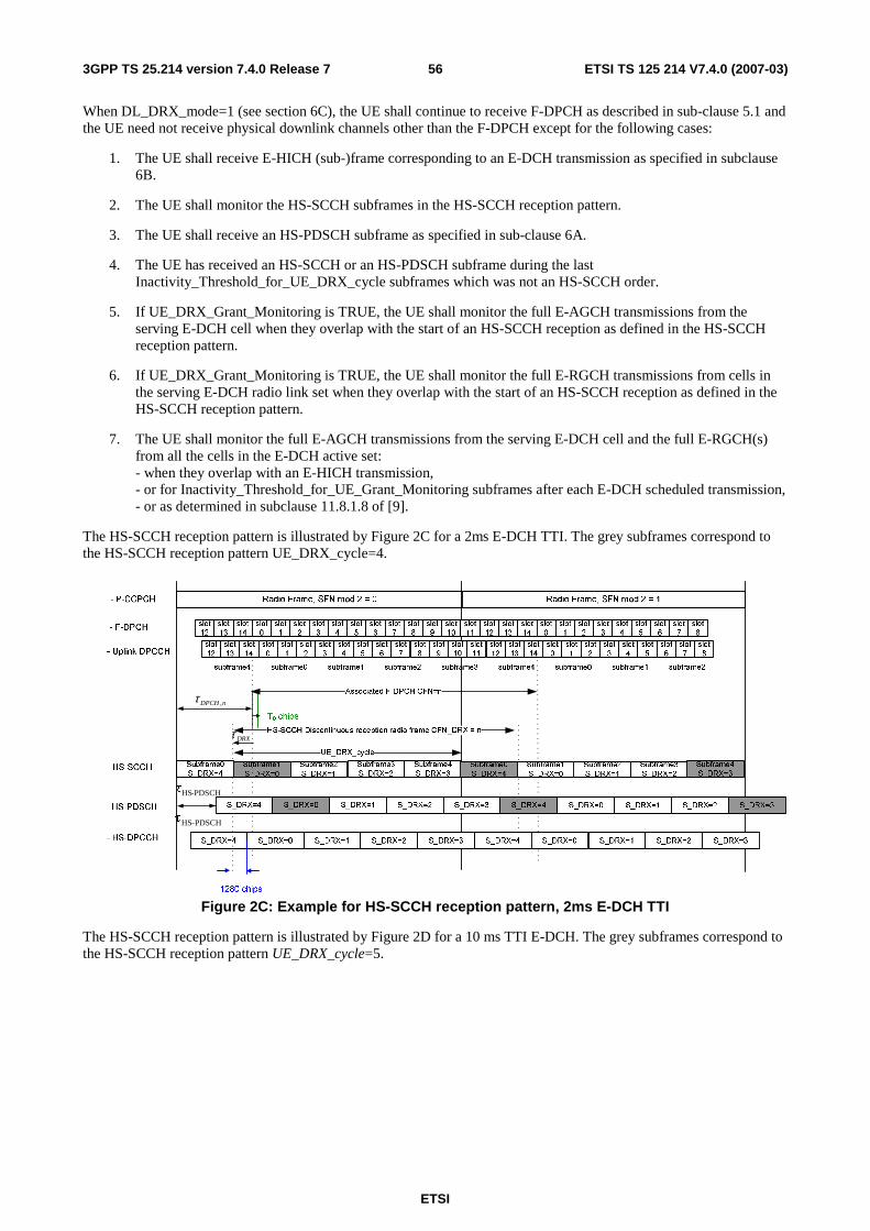
ETSI
ETSI TS 125 214 V7.4.0 (2007-03) 563GPP TS 25.214 version 7.4.0 Release 7
When DL_DRX_mode=1 (see section 6C), the UE shall continue to receive F-DPCH as described in sub-clause 5.1 and the UE need not receive physical downlink channels other than the F-DPCH except for the following cases:
1. The UE shall receive E-HICH (sub-)frame corresponding to an E-DCH transmission as specified in subclause 6B.
2. The UE shall monitor the HS-SCCH subframes in the HS-SCCH reception pattern.
3. The UE shall receive an HS-PDSCH subframe as specified in sub-clause 6A.
4. The UE has received an HS-SCCH or an HS-PDSCH subframe during the last Inactivity_Threshold_for_UE_DRX_cycle subframes which was not an HS-SCCH order.
5. If UE_DRX_Grant_Monitoring is TRUE, the UE shall monitor the full E-AGCH transmissions from the serving E-DCH cell when they overlap with the start of an HS-SCCH reception as defined in the HS-SCCH reception pattern.
6. If UE_DRX_Grant_Monitoring is TRUE, the UE shall monitor the full E-RGCH transmissions from cells in the serving E-DCH radio link set when they overlap with the start of an HS-SCCH reception as defined in the HS-SCCH reception pattern.
7. The UE shall monitor the full E-AGCH transmissions from the serving E-DCH cell and the full E-RGCH(s) from all the cells in the E-DCH active set: - when they overlap with an E-HICH transmission, - or for Inactivity_Threshold_for_UE_Grant_Monitoring subframes after each E-DCH scheduled transmission, - or as determined in subclause 11.8.1.8 of [9].
The HS-SCCH reception pattern is illustrated by Figure 2C for a 2ms E-DCH TTI. The grey subframes correspond to the HS-SCCH reception pattern UE_DRX_cycle=4.
nDPCH ,τ
DRXτ
PDSCH-HSτ
PDSCH-HSτ
Figure 2C: Example for HS-SCCH reception pattern, 2ms E-DCH TTI
The HS-SCCH reception pattern is illustrated by Figure 2D for a 10 ms TTI E-DCH. The grey subframes correspond to the HS-SCCH reception pattern UE_DRX_cycle=5.
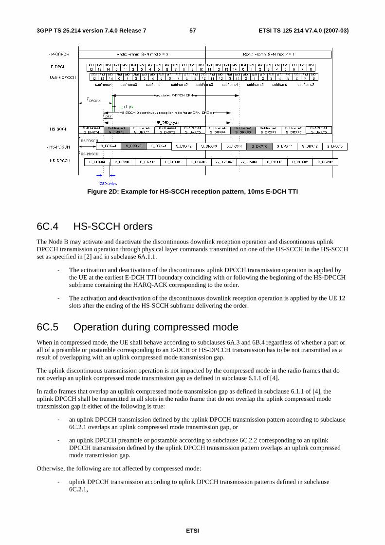
ETSI
ETSI TS 125 214 V7.4.0 (2007-03) 573GPP TS 25.214 version 7.4.0 Release 7
- P-CCPCH Radio Frame, SFN mod 2 = 0 Radio Frame, SFN mod 2 = 1
subframe0 subframe1 subframe2 subframe3 subframe4subframe4 subframe0 subframe1 subframe2
T0 chips
- HS-SCCH Subframe1
S_DRX=0
Subframe2
S_DRX=1
Subframe3
S_DRX=2
Subframe4
S_DRX=3
nDPCH ,τ
DRXτ
Subframe0
S_DRX=4
Subframe2
S_DRX=1
Subframe3
S_DRX=2
- Uplink DPCCHslot
12
slot
13
slot
14
slot
0
slot
1
slot
2
slot
3
slot
4
slot
5
slot
6
slot
7
slot
8
slot
9
slot
10
slot
11
slot
12
slot
13
slot
0
slot
1
slot
2
slot
3
slot
4
slot
5
slot
6
slot
7
slot
8
UE_DRX_cycle
PDSCH-HSτ
Associated F-DPCH CFN=n
- HS-PDSCH
HS-SCCH Discontinuous reception radio frame CFN_DRX = n
- HS-DPCCH
S_DRX=4 S_DRX=0 S_DRX=1 S_DRX=2 S_DRX=3 S_DRX=4
PDSCH-HSτ
S_DRX=0 S_DRX=1 S_DRX=2
S_DRX=0 S_DRX=1 S_DRX=2 S_DRX=3 S_DRX=4 S_DRX=0 S_DRX=1 S_DRX=2
S_DRX=3
S_DRX=4
1280 chips
slot
12
slot
13
slot
14
slot
0
slot
1
slot
2
slot
3
slot
4
slot
5
slot
6
slot
7
slot
8
slot
9
slot
10
slot
11
slot
12
slot
13
slot
14
slot
0
slot
1
slot
2
slot
3
slot
4
slot
5
slot
6
slot
7
slot
8- F-DPCH
Subframe0
S_DRX=4
Subframe4
S_DRX=3
S_DRX=3
slot
14
Subframe1
S_DRX=0
Figure 2D: Example for HS-SCCH reception pattern, 10ms E-DCH TTI
6C.4 HS-SCCH orders The Node B may activate and deactivate the discontinuous downlink reception operation and discontinuous uplink DPCCH transmission operation through physical layer commands transmitted on one of the HS-SCCH in the HS-SCCH set as specified in [2] and in subclause 6A.1.1.
- The activation and deactivation of the discontinuous uplink DPCCH transmission operation is applied by the UE at the earliest E-DCH TTI boundary coinciding with or following the beginning of the HS-DPCCH subframe containing the HARQ-ACK corresponding to the order.
- The activation and deactivation of the discontinuous downlink reception operation is applied by the UE 12 slots after the ending of the HS-SCCH subframe delivering the order.
6C.5 Operation during compressed mode When in compressed mode, the UE shall behave according to subclauses 6A.3 and 6B.4 regardless of whether a part or all of a preamble or postamble corresponding to an E-DCH or HS-DPCCH transmission has to be not transmitted as a result of overlapping with an uplink compressed mode transmission gap.
The uplink discontinuous transmission operation is not impacted by the compressed mode in the radio frames that do not overlap an uplink compressed mode transmission gap as defined in subclause 6.1.1 of [4].
In radio frames that overlap an uplink compressed mode transmission gap as defined in subclause 6.1.1 of [4], the uplink DPCCH shall be transmitted in all slots in the radio frame that do not overlap the uplink compressed mode transmission gap if either of the following is true:
- an uplink DPCCH transmission defined by the uplink DPCCH transmission pattern according to subclause 6C.2.1 overlaps an uplink compressed mode transmission gap, or
- an uplink DPCCH preamble or postamble according to subclause 6C.2.2 corresponding to an uplink DPCCH transmission defined by the uplink DPCCH transmission pattern overlaps an uplink compressed mode transmission gap.
Otherwise, the following are not affected by compressed mode:
- uplink DPCCH transmission according to uplink DPCCH transmission patterns defined in subclause 6C.2.1,
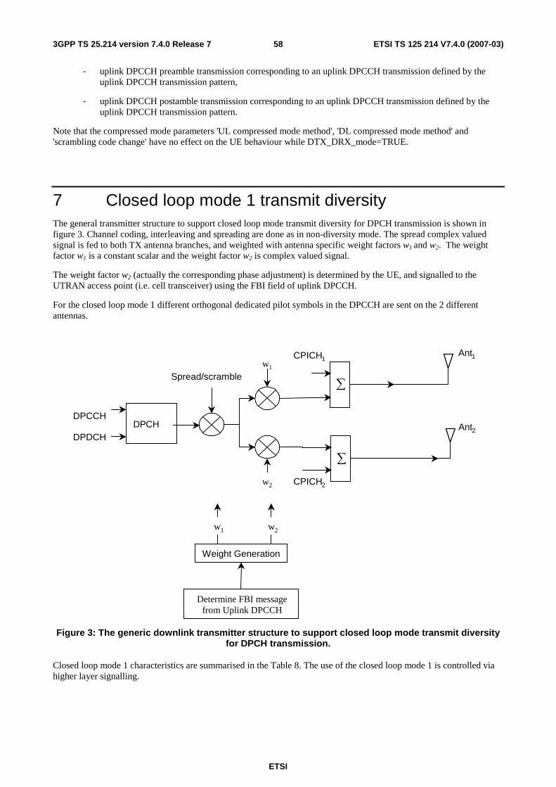
ETSI
ETSI TS 125 214 V7.4.0 (2007-03) 583GPP TS 25.214 version 7.4.0 Release 7
- uplink DPCCH preamble transmission corresponding to an uplink DPCCH transmission defined by the uplink DPCCH transmission pattern,
- uplink DPCCH postamble transmission corresponding to an uplink DPCCH transmission defined by the uplink DPCCH transmission pattern.
Note that the compressed mode parameters 'UL compressed mode method', 'DL compressed mode method' and 'scrambling code change' have no effect on the UE behaviour while DTX_DRX_mode=TRUE.
7 Closed loop mode 1 transmit diversity The general transmitter structure to support closed loop mode transmit diversity for DPCH transmission is shown in figure 3. Channel coding, interleaving and spreading are done as in non-diversity mode. The spread complex valued signal is fed to both TX antenna branches, and weighted with antenna specific weight factors w1 and w2. The weight factor w1 is a constant scalar and the weight factor w2 is complex valued signal.
The weight factor w2 (actually the corresponding phase adjustment) is determined by the UE, and signalled to the UTRAN access point (i.e. cell transceiver) using the FBI field of uplink DPCCH.
For the closed loop mode 1 different orthogonal dedicated pilot symbols in the DPCCH are sent on the 2 different antennas.
Spread/scramblew1
w2
DPCHDPCCH
DPDCH
∑
CPICH1
∑
CPICH2
Ant1
Ant2
Weight Generation
w1 w2
Determine FBI messagefrom Uplink DPCCH
Figure 3: The generic downlink transmitter structure to support closed loop mode transmit diversity for DPCH transmission.
Closed loop mode 1 characteristics are summarised in the Table 8. The use of the closed loop mode 1 is controlled via higher layer signalling.
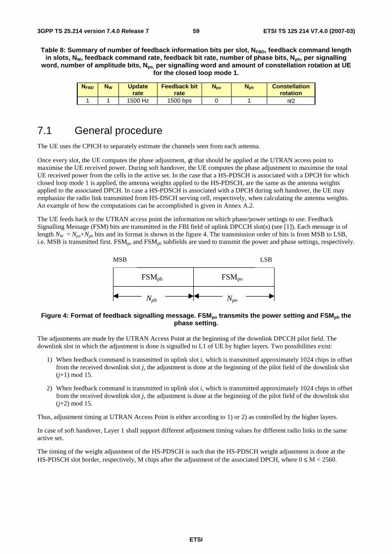
ETSI
ETSI TS 125 214 V7.4.0 (2007-03) 593GPP TS 25.214 version 7.4.0 Release 7
Table 8: Summary of number of feedback information bits per slot, NFBD, feedback command length in slots, NW, feedback command rate, feedback bit rate, number of phase bits, Nph, per signalling
word, number of amplitude bits, Npo, per signalling word and amount of constellation rotation at UE for the closed loop mode 1.
NFBD NW Update rate
Feedback bit rate
Npo Nph Constellation rotation
1 1 1500 Hz 1500 bps 0 1 π/2
7.1 General procedure The UE uses the CPICH to separately estimate the channels seen from each antenna.
Once every slot, the UE computes the phase adjustment, φ, that should be applied at the UTRAN access point to maximise the UE received power. During soft handover, the UE computes the phase adjustment to maximise the total UE received power from the cells in the active set. In the case that a HS-PDSCH is associated with a DPCH for which closed loop mode 1 is applied, the antenna weights applied to the HS-PDSCH, are the same as the antenna weights applied to the associated DPCH. In case a HS-PDSCH is associated with a DPCH during soft handover, the UE may emphasize the radio link transmitted from HS-DSCH serving cell, respectively, when calculating the antenna weights. An example of how the computations can be accomplished is given in Annex A.2.
The UE feeds back to the UTRAN access point the information on which phase/power settings to use. Feedback Signalling Message (FSM) bits are transmitted in the FBI field of uplink DPCCH slot(s) (see [1]). Each message is of length NW = Npo+Nph bits and its format is shown in the figure 4. The transmission order of bits is from MSB to LSB, i.e. MSB is transmitted first. FSMpo and FSMph subfields are used to transmit the power and phase settings, respectively.
FSMph
MSB LSB
FSMpo
Nph Npo
Figure 4: Format of feedback signalling message. FSMpo transmits the power setting and FSMph the phase setting.
The adjustments are made by the UTRAN Access Point at the beginning of the downlink DPCCH pilot field. The downlink slot in which the adjustment is done is signalled to L1 of UE by higher layers. Two possibilities exist:
1) When feedback command is transmitted in uplink slot i, which is transmitted approximately 1024 chips in offset from the received downlink slot j, the adjustment is done at the beginning of the pilot field of the downlink slot (j+1) mod 15.
2) When feedback command is transmitted in uplink slot i, which is transmitted approximately 1024 chips in offset from the received downlink slot j, the adjustment is done at the beginning of the pilot field of the downlink slot (j+2) mod 15.
Thus, adjustment timing at UTRAN Access Point is either according to 1) or 2) as controlled by the higher layers.
In case of soft handover, Layer 1 shall support different adjustment timing values for different radio links in the same active set.
The timing of the weight adjustment of the HS-PDSCH is such that the HS-PDSCH weight adjustment is done at the HS-PDSCH slot border, respectively, M chips after the adjustment of the associated DPCH, where 0 ≤ M < 2560.
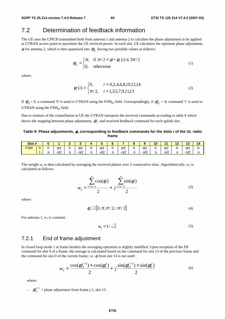
ETSI
ETSI TS 125 214 V7.4.0 (2007-03) 603GPP TS 25.214 version 7.4.0 Release 7
7.2 Determination of feedback information The UE uses the CPICH transmitted both from antenna 1 and antenna 2 to calculate the phase adjustment to be applied at UTRAN access point to maximise the UE received power. In each slot, UE calculates the optimum phase adjustment,
φ, for antenna 2, which is then quantized into Qφ having two possible values as follows:
≤−<
=otherwise,0
2/3)(2/ if, πφφππφ
irQ (1)
where:
==
=13,11,9,7,5,3,1,2/
14,12,10,8,6,4,2,0,0)(
i
iir π
φ (2)
If Qφ = 0, a command '0' is send to UTRAN using the FSMph field. Correspondingly, if Qφ = π, command '1' is send to
UTRAN using the FSMph field.
Due to rotation of the constellation at UE the UTRAN interprets the received commands according to table 9 which
shows the mapping between phase adjustment, iφ , and received feedback command for each uplink slot.
Table 9: Phase adjustments, φφφφi, corresponding to feedback commands for the slots i of the UL radio frame
Slot # 0 1 2 3 4 5 6 7 8 9 10 11 12 13 14 FSM 0 0 π/2 0 π/2 0 π/2 0 π/2 0 π/2 0 π/2 0 π/2 0
1 π -π/2 π -π/2 π -π/2 π -π/2 π -π/2 π -π/2 π -π/2 π
The weight w2 is then calculated by averaging the received phases over 2 consecutive slots. Algorithmically, w2 is calculated as follows:
2
)sin(
2
)cos(11
2
∑∑−=−= +=
n
nii
n
nii
jw
φφ (3)
where:
{ }2/,2/,,0 πππφ −∈i (4)
For antenna 1, w1 is constant:
2/11 =w (5)
7.2.1 End of frame adjustment
In closed loop mode 1 at frame borders the averaging operation is slightly modified. Upon reception of the FB command for slot 0 of a frame, the average is calculated based on the command for slot 13 of the previous frame and the command for slot 0 of the current frame, i.e. φi from slot 14 is not used:
2
)sin()sin(
2
)cos()cos( 01
1301
132
jjjj
jwφφφφ +++=
−− (6)
where:
- 113
−jφ = phase adjustment from frame j-1, slot 13.
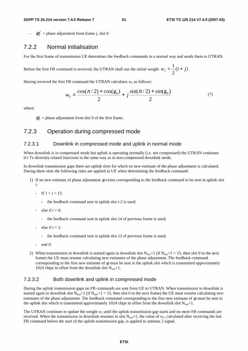
ETSI
ETSI TS 125 214 V7.4.0 (2007-03) 613GPP TS 25.214 version 7.4.0 Release 7
- j0φ = phase adjustment from frame j, slot 0.
7.2.2 Normal initialisation
For the first frame of transmission UE determines the feedback commands in a normal way and sends them to UTRAN.
Before the first FB command is received, the UTRAN shall use the initial weight )1(2
12 jw += .
Having received the first FB command the UTRAN calculates w2 as follows:
2
)sin()2/sin(
2
)cos()2/cos( 002
φπφπ +++= jw (7)
where:
0φ = phase adjustment from slot 0 of the first frame.
7.2.3 Operation during compressed mode
7.2.3.1 Downlink in compressed mode and uplink in normal mode
When downlink is in compressed mode but uplink is operating normally (i.e. not compressed) the UTRAN continues it's Tx diversity related functions in the same way as in non-compressed downlink mode.
In downlink transmission gaps there are uplink slots for which no new estimate of the phase adjustment is calculated. During these slots the following rules are applied in UE when determining the feedback command:
1) If no new estimate of phase adjustment φi exists corresponding to the feedback command to be sent in uplink slot i:
- If 1 < i < 15:
- the feedback command sent in uplink slot i-2 is used;
- else if i = 0:
- the feedback command sent in uplink slot 14 of previous frame is used;
- else if i = 1:
- the feedback command sent in uplink slot 13 of previous frame is used;
- end if.
2) When transmission in downlink is started again in downlink slot Nlast+1 (if Nlast+1 = 15, then slot 0 in the next frame) the UE must resume calculating new estimates of the phase adjustment. The feedback command corresponding to the first new estimate of φi must be sent in the uplink slot which is transmitted approximately 1024 chips in offset from the downlink slot Nlast+1.
7.2.3.2 Both downlink and uplink in compressed mode
During the uplink transmission gaps no FB commands are sent from UE to UTRAN. When transmission in downlink is started again in downlink slot Nlast+1 (if Nlast+1 = 15, then slot 0 in the next frame) the UE must resume calculating new estimates of the phase adjustment. The feedback command corresponding to the first new estimate of φi must be sent in the uplink slot which is transmitted approximately 1024 chips in offset from the downlink slot Nlast+1.
The UTRAN continues to update the weight w2 until the uplink transmission gap starts and no more FB commands are received. When the transmission in downlink resumes in slot Nlast+1, the value of w2, calculated after receiving the last FB command before the start of the uplink transmission gap, is applied to antenna 2 signal.
ETSI
ETSI TS 125 214 V7.4.0 (2007-03) 623GPP TS 25.214 version 7.4.0 Release 7
After the UE resumes transmission in uplink and sends the first FB command, the new value of w2 is calculated as follows:
- S1 = {0, 2, 4, 6, 8, 10, 12 14}.
- S2 = {1, 3, 5, 7, 9, 11, 13}.
- i = number of uplink slot at which the transmission resumes.
- j = number of uplink slot at which the last FB command was sent before the start of the uplink transmission gap.
- Do while ( 11 SjandSi ∈∈ ) or ( 22 SjandSi ∈∈ ):
- j = j-1;
- if j < 0;
- j = 14;
- end if;
- end do;
- calculate w2 based on FB commands received in uplink slots i and j.
Note that for Nlast = 13 the end of frame adjustment procedure shall be based on the FB commands for the last odd slot prior to the uplink transmission gap and slot 0.
7.2.3.3 Uplink in compressed mode and downlink in normal mode
The UTRAN continues to update the value of w2 until the uplink transmission gap starts and no more FB commands are received. Then, the value of w2 calculated after receiving the last FB command before the uplink transmission gap is applied to the antenna 2 signal. When the UE resumes transmission in uplink, it shall send FB commands according to section 7.2 equations 2 and 3 (normal operation) and the UTRAN Access Point shall interpret the FB commands according to Table 9.
The calculation of w2 by the UTRAN following the uplink transmission gap, and before the first two FB commands following the gap are received is not specified.
7.2.4 Initialisation during compressed mode
7.2.4.1 Downlink in compressed mode
When closed loop mode 1 is initialised during the downlink transmission gap of compressed mode there are slots for which no estimate of the phase adjustment is calculated and no previous feedback command is available.
In this case, if the UE is required to send feedback in the uplink, the FB command to the UTRAN shall be "0".
When transmission in downlink is started again in slot Nlast+1 (if Nlast+1 = 15, then slot 0 in the next frame), the
UTRAN shall use the initial weight )1(2
12 jw += . The UE must start calculating estimates of the phase adjustment.
The feedback command corresponding to the first estimate of φi must be sent in the uplink slot which is transmitted approximately 1024 chips in offset from the downlink slot Nlast+1. Having received this feedback command the UTRAN calculates w2 as follows:
2
)sin()sin(
2
)cos()cos(2
jiji jwφφφφ +
++
= (8)
where:
ETSI
ETSI TS 125 214 V7.4.0 (2007-03) 633GPP TS 25.214 version 7.4.0 Release 7
iφ = phase adjustment in uplink slot i , which is transmitted approximately 1024 chips in offset from the downlink
slot Nlast+1.
2
πφ =j , if slot i is even ( }14,12,10,8,6,4,2,0{∈i ) and
0=jφ , if slot i is odd ( }13,11,9,7,5,3,1{∈i )
7.2.4.2 Uplink in compressed mode
Initialisation of closed loop mode 1 operation during uplink compressed mode only is not specified.
7.3 Void
8 Idle periods for IPDL location method
8.1 General To support time difference measurements for location services, idle periods can be created in the downlink (hence the name IPDL) during which time transmission of all channels from a Node B is temporarily seized. During these idle periods the visibility of neighbour cells from the UE is improved.
The idle periods are arranged in a predetermined pseudo random fashion according to higher layer parameters. Idle periods differ from compressed mode in that they are shorter in duration, all channels are silent simultaneously, and no attempt is made to prevent data loss.
In general there are two modes for these idle periods:
- Continuous mode, and
- Burst mode.
In continuous mode the idle periods are active all the time. In burst mode the idle periods are arranged in bursts where each burst contains enough idle periods to allow a UE to make sufficient measurements for its location to be calculated. The bursts are separated by a period where no idle periods occur.
8.2 Parameters of IPDL The following parameters are signalled to the UE via higher layers:
IP_Status: This is a logic value that indicates if the idle periods are arranged in continuous or burst mode.
IP_Spacing: The number of 10 ms radio frames between the start of a radio frame that contains an idle period and the next radio frame that contains an idle period. Note that there is at most one idle period in a radio frame.
IP_Length: The length of the idle periods, expressed in symbols of the CPICH.
IP_Offset: A cell specific offset that can be used to synchronise idle periods from different sectors within a Node B.
Seed: Seed for the pseudo random number generator.
Additionally in the case of burst mode operation the following parameters are also communicated to the UE.
Burst_Start: Specifies the start of the first burst of idle periods. 256×Burst_Start is the SFN where the first burst of idle periods starts.
ETSI
ETSI TS 125 214 V7.4.0 (2007-03) 643GPP TS 25.214 version 7.4.0 Release 7
Burst_Length: The number of idle periods in a burst of idle periods.
Burst_Freq: Specifies the time between the start of a burst and the start of the next burst. 256×Burst_Freq is the number of radio frames of the primary CPICH between the start of a burst and the start of the next burst.
8.3 Calculation of idle period position In burst mode, burst #0 starts in the radio frame with SFN = 256×Burst_Start. Burst #k starts in the radio frame with SFN = 256×Burst_Start + k×256×Burst_Freq( k = 0,1,2, …). The sequence of bursts according to this formula continues up to and including the radio frame with SFN = 4095. At the start of the radio frame with SFN = 0, the burst sequence is terminated (no idle periods are generated) and at SFN = 256×Burst_Start the burst sequence is restarted with burst #0 followed by burst #1 etc., as described above.
Continuous mode is equivalent to burst mode, with only one burst spanning the whole SFN cycle of 4096 radio frames, this burst starting in the radio frame with SFN = 0.
Assume that IP_Position(x) is the position of idle period number x within a burst, where x = 1, 2, …, and IP_Position(x) is measured in number of CPICH symbols from the start of the first radio frame of the burst.
The positions of the idle periods within each burst are then given by the following equation:
IP_Position(x) = (x × IP_Spacing × 150) + (rand(x modulo 64) modulo (150 – IP_Length)) + IP_Offset;
where rand(m) is a pseudo random generator defined as follows:
rand(0) = Seed;
rand(m) = (106×rand(m – 1) + 1283) modulo 6075, m = 1, 2, 3, ….
Note that x is reset to x = 1 for the first idle period in every burst.
Figure 6 below illustrates the idle periods for the burst mode case.
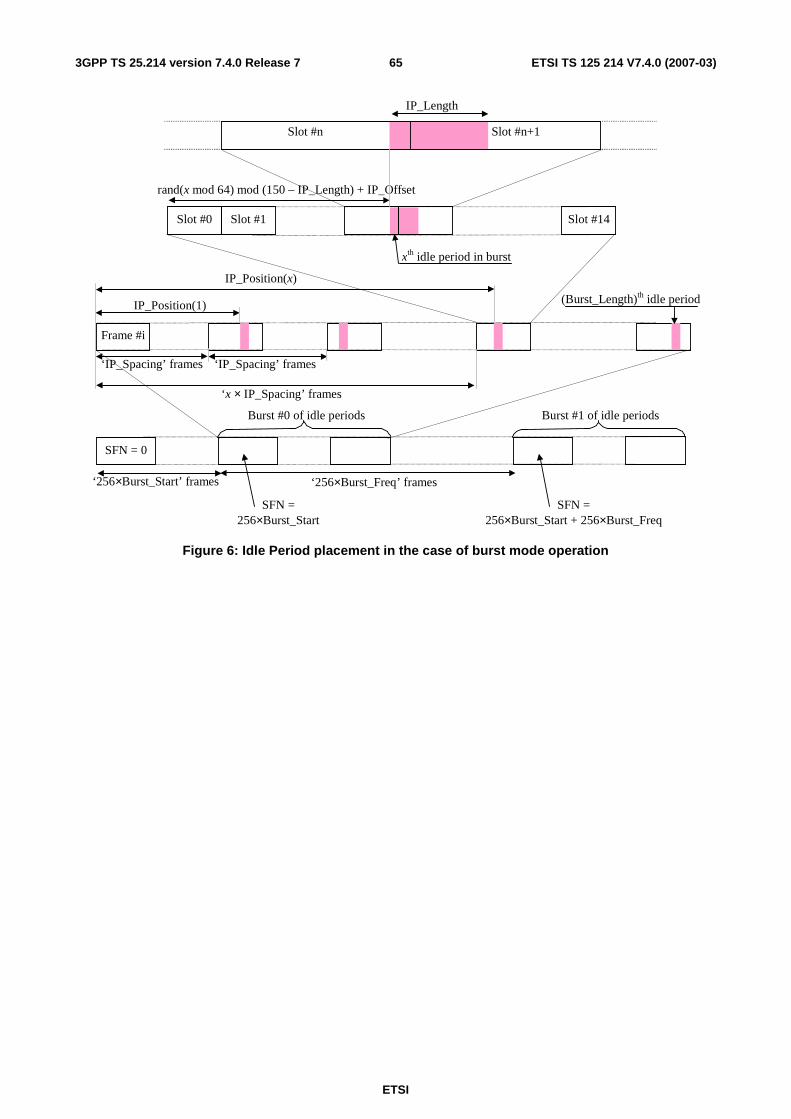
ETSI
ETSI TS 125 214 V7.4.0 (2007-03) 653GPP TS 25.214 version 7.4.0 Release 7
Slot #n+1 Slot #n
(Burst_Length)th idle period
IP_Length
‘x × IP_Spacing’ frames
IP_Position(x)
IP_Position(1)
xth idle period in burst
rand(x mod 64) mod (150 – IP_Length) + IP_Offset
‘256×Burst_Freq’ frames
Burst #0 of idle periods
Frame #i
SFN = 0
‘IP_Spacing’ frames
‘256×Burst_Start’ frames
Burst #1 of idle periods
‘IP_Spacing’ frames
Slot #0 Slot #1 Slot #14
SFN = 256×Burst_Start
SFN = 256×Burst_Start + 256×Burst_Freq
Figure 6: Idle Period placement in the case of burst mode operation
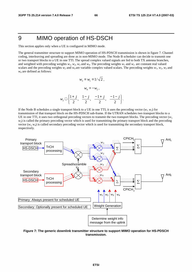
ETSI
ETSI TS 125 214 V7.4.0 (2007-03) 663GPP TS 25.214 version 7.4.0 Release 7
9 MIMO operation of HS-DSCH This section applies only when a UE is configured in MIMO mode.
The general transmitter structure to support MIMO operation of HS-PDSCH transmission is shown in figure 7. Channel coding, interleaving and spreading are done as in non-MIMO mode. The Node B scheduler can decide to transmit one or two transport blocks to a UE in one TTI. The spread complex valued signals are fed to both TX antenna branches, and weighted with precoding weights w1, w2, w3 and w4. The precoding weights w1 and w3 are constant real valued scalars and the precoding weights w2 and w4 are variable complex valued scalars. The precoding weights w1, w2, w3 and w4 are defined as follows:
2/113 == ww ,
24 ww −= ,
−−+−−+∈
21
,2
1,
21
,2
12
jjjjw .
If the Node B schedules a single transport block to a UE in one TTI, it uses the precoding vector (w1, w2) for transmission of that transport block on the HS-PDSCH sub-frame. If the UTRAN schedules two transport blocks to a UE in one TTI, it uses two orthogonal precoding vectors to transmit the two transport blocks. The precoding vector (w1,
w2) is called the primary precoding vector which is used for transmitting the primary transport block and the precoding vector (w3, w4) is called secondary precoding vector which is used for transmitting the secondary transport block, respectively.
Weight Generation
w 1 w 4
Determine weight info message from the uplink
w 2 w 3
TrCH processing
HS-DSCH TrCH processing
HS-DSCH
Spread/scramble
∑
Ant 1
Ant 2
∑
CPICH 1
CPICH 2
w 1
w 2
w 3
w 4
∑
∑
Primary transport block
Primary: Always present for scheduled UE
Secondary: Optionally present for scheduled UE
Secondary transport block
Figure 7: The generic downlink transmitter structure to support MIMO operation for HS-PDSCH transmission.
ETSI
ETSI TS 125 214 V7.4.0 (2007-03) 673GPP TS 25.214 version 7.4.0 Release 7
9.1 General procedure The UE uses the CPICH to separately estimate the channels seen from each antenna. One of the antennas will transmit the Antenna 1 modulation pattern of the P-CPICH as defined in subclause 5.3.3.1 of [1]. The other antenna will transmit either the Antenna 2 modulation pattern of the P-CPICH or the Antenna 1 modulation pattern of a S-CPICH. The Pilot configuration in support of MIMO operation of HS-DSCH in the cell is signalled by higher layers.
The UE determines a preferred primary precoding vector ( )pref2
pref1 , ww and signals it to the Node B. The signalled
information about the preferred primary precoding vector is termed precoding control indication (PCI) and is defined in subclause 6A.4. The PCI is signalled to the Node B together with channel quality indication (CQI) as a composite PCI/CQI report according to the procedure defined in subclause 6A.1.2.2. The UE transmits the composite PCI/CQI report to the Node B using the CQI field on the HS-DPCCH as defined in [1]. Based on the composite PCI/CQI reports, the Node B scheduler decides whether to schedule one or two transport blocks to a UE in one TTI and what tranport block size(s) and modulation scheme(s) to use for each of them.
The Node B signals to the UE the precoding weight w2 applied on the HS-PDSCH sub-frame using the precoding weight indication bits of part 1 of the corresponding HS-SCCH sub-frame. The precoding weight adjustment of each HS-PDSCH is done at the HS-PDSCH sub-frame border.
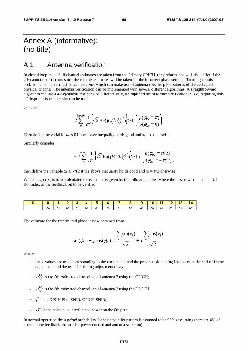
ETSI
ETSI TS 125 214 V7.4.0 (2007-03) 683GPP TS 25.214 version 7.4.0 Release 7
Annex A (informative): (no title)
A.1 Antenna verification In closed loop mode 1, if channel estimates are taken from the Primary CPICH, the performance will also suffer if the UE cannot detect errors since the channel estimates will be taken for the incorrect phase settings. To mitigate this problem, antenna verification can be done, which can make use of antenna specific pilot patterns of the dedicated physical channel. The antenna verification can be implemented with several different algorithms. A straightforward algorithm can use a 4-hypothesis test per slot. Alternatively, a simplified beam former verification (SBV) requiring only a 2-hypothesis test per slot can be used.
Consider
{ }
==>∑
= )0(
)(ln)Re(2
12
*)(,2
)(,2
12
Rx
Rxpi
di
Npath
i i p
phh
φπφγ
σ
Then define the variable x0 as 0 if the above inequality holds good and x0 = π otherwise.
Similarly consider
{ }
−==
>− ∑= )2(
)2(ln)Im(2
12
*)(,2
)(,2
12 πφ
πφγσ Rx
Rxpi
di
Npath
i i p
phh
then define the variable x1 as -π/2 if the above inequality holds good and x1 = π/2 oherwise.
Whether x0 or x1 is to be calculated for each slot is given by the following table , where the first row contains the UL slot index of the feedback bit to be verified.
UL 0 1 2 3 4 5 6 7 8 9 10 11 12 13 14 x0 x1 x0 x1 x0 x1 x0 x1 x0 x1 x0 x1 x0 x1 x0
The estimate for the transmitted phase is now obtained from
2
)cos(
2
)sin(
)cos()sin(
1
0
1
0∑∑== +=+ i
ii
i
TxTx
x
j
x
j φφ
where:
- the xi values are used corresponding to the current slot and the previous slot taking into account the end-of-frame adjustment and the used CL timing adjustment delay
- )(,2pih is the i'th estimated channel tap of antenna 2 using the CPICH;
- )(,2dih is the i'th estimated channel tap of antenna 2 using the DPCCH;
− γ2 is the DPCH Pilot SNIR/ CPICH SNIR;
- 2iσ is the noise plus interference power on the i'th path.
In normal operation the a priori probability for selected pilot pattern is assumed to be 96% (assuming there are 4% of errors in the feedback channel for power control and antenna selection).
ETSI
ETSI TS 125 214 V7.4.0 (2007-03) 693GPP TS 25.214 version 7.4.0 Release 7
A.2 Computation of feedback information for closed loop mode 1 transmit diversity
In non-soft handover case, the computation of feedback information can be accomplished by e.g. solving for weight vector, w, that maximises.
P=wHHHHw (1)
where
H=[h1 h2] and w = [ w1, w2 ]T
and where the column vectors h1 and h2 represent the estimated channel impulse responses for the transmission antennas 1 and 2, of length equal to the length of the channel impulse response. The elements of w correspond to the adjustments computed by the UE.
During soft handover, the antenna weight vector, w can be, for example, determined so as to maximise the criteria function:
P = wH(H1HH1+ H2
HH2+⋅⋅⋅⋅)w (2)
where Hi is an estimated channel impulse response for BS#i. In regular SHO, the set of BS#i corresponds to the active set.
If HS-PDSCH is present, the UE may emphasize the HS-PDSCH serving cell. In this case the antenna weight vector, w can be, for example, determined so as to maximise the criteria function:
P = wH(α(H1HH1)+ (1-α)(H2
HH2+⋅⋅⋅⋅))w
where BS#1 is the HS-PDSCH serving cell and coefficient α is less than or equal to 1. For example α = 0.7 enhances HS-DSCH performance while ensuring that there is only a small degradation on the DPCH.
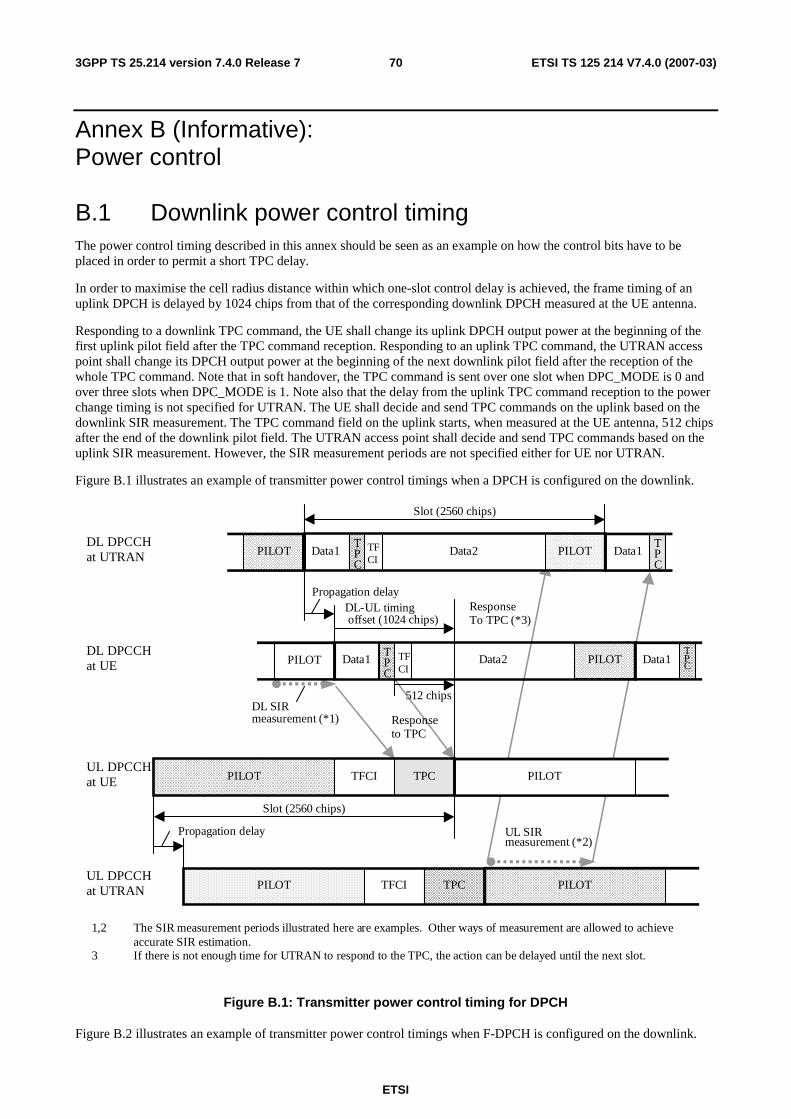
ETSI
ETSI TS 125 214 V7.4.0 (2007-03) 703GPP TS 25.214 version 7.4.0 Release 7
Annex B (Informative): Power control
B.1 Downlink power control timing The power control timing described in this annex should be seen as an example on how the control bits have to be placed in order to permit a short TPC delay.
In order to maximise the cell radius distance within which one-slot control delay is achieved, the frame timing of an uplink DPCH is delayed by 1024 chips from that of the corresponding downlink DPCH measured at the UE antenna.
Responding to a downlink TPC command, the UE shall change its uplink DPCH output power at the beginning of the first uplink pilot field after the TPC command reception. Responding to an uplink TPC command, the UTRAN access point shall change its DPCH output power at the beginning of the next downlink pilot field after the reception of the whole TPC command. Note that in soft handover, the TPC command is sent over one slot when DPC_MODE is 0 and over three slots when DPC_MODE is 1. Note also that the delay from the uplink TPC command reception to the power change timing is not specified for UTRAN. The UE shall decide and send TPC commands on the uplink based on the downlink SIR measurement. The TPC command field on the uplink starts, when measured at the UE antenna, 512 chips after the end of the downlink pilot field. The UTRAN access point shall decide and send TPC commands based on the uplink SIR measurement. However, the SIR measurement periods are not specified either for UE nor UTRAN.
Figure B.1 illustrates an example of transmitter power control timings when a DPCH is configured on the downlink.
Data2Data1
1,2 The SIR measurement periods illustrated here are examples. Other ways of measurement are allowed to achieve accurate SIR estimation.3 If there is not enough time for UTRAN to respond to the TPC, the action can be delayed until the next slot.
Data1TPC
Data1TPC
PILOTPILOT
PILOT
ResponseTo TPC (*3)
TPC
DL SIRmeasurement (*1)
PILOT TFCI TPC
DL-UL timing offset (1024 chips)
Slot (2560 chips)
PILOTPILOT Data2Data1TPC
PILOTPILOT TFCI TPC
Slot (2560 chips)
Propagation delay
UL SIRmeasurement (*2)
Responseto TPC
DL DPCCHat UTRAN
Propagation delay
DL DPCCHat UE
UL DPCCHat UTRAN
UL DPCCHat UE
512 chips
TFCI
TFCI
Figure B.1: Transmitter power control timing for DPCH
Figure B.2 illustrates an example of transmitter power control timings when F-DPCH is configured on the downlink.
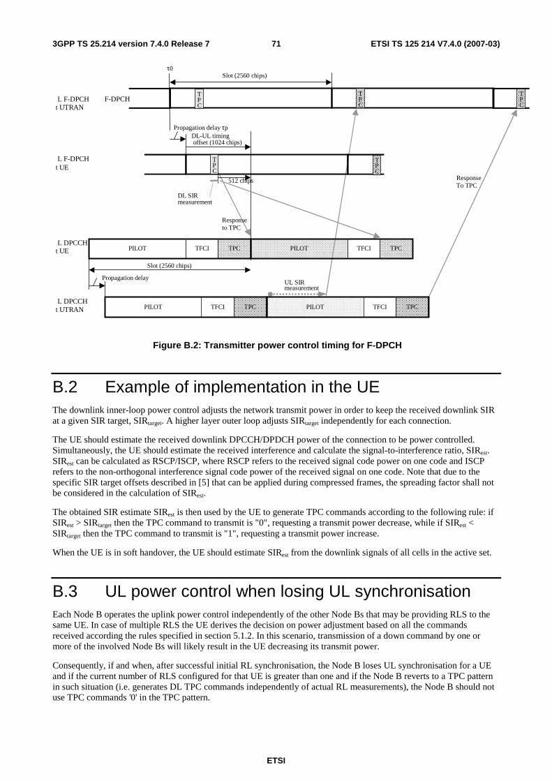
ETSI
ETSI TS 125 214 V7.4.0 (2007-03) 713GPP TS 25.214 version 7.4.0 Release 7
PILOT TFCI TPC PILOT TFCI TPC
PILOT TFCI TPC PILOT TFCI TPC
Response To TPC
DL SIR measurement
DL-UL timing offset (1024 chips)
Slot (2560 chips)
Propagation delay τp
UL SIR measurement
Response to TPC
L F-DPCH t UTRAN
Propagation delay
L F-DPCH t UE
L DPCCH t UTRAN
L DPCCH t UE
512 chips
Slot (2560 chips)
T P C
T PC
τ0
T P C
T P C
F-DPCH T PC
Figure B.2: Transmitter power control timing for F-DPCH
B.2 Example of implementation in the UE The downlink inner-loop power control adjusts the network transmit power in order to keep the received downlink SIR at a given SIR target, SIRtarget. A higher layer outer loop adjusts SIRtarget independently for each connection.
The UE should estimate the received downlink DPCCH/DPDCH power of the connection to be power controlled. Simultaneously, the UE should estimate the received interference and calculate the signal-to-interference ratio, SIRest. SIRest can be calculated as RSCP/ISCP, where RSCP refers to the received signal code power on one code and ISCP refers to the non-orthogonal interference signal code power of the received signal on one code. Note that due to the specific SIR target offsets described in [5] that can be applied during compressed frames, the spreading factor shall not be considered in the calculation of SIRest.
The obtained SIR estimate SIRest is then used by the UE to generate TPC commands according to the following rule: if SIRest > SIRtarget then the TPC command to transmit is "0", requesting a transmit power decrease, while if SIRest < SIRtarget then the TPC command to transmit is "1", requesting a transmit power increase.
When the UE is in soft handover, the UE should estimate SIRest from the downlink signals of all cells in the active set.
B.3 UL power control when losing UL synchronisation Each Node B operates the uplink power control independently of the other Node Bs that may be providing RLS to the same UE. In case of multiple RLS the UE derives the decision on power adjustment based on all the commands received according the rules specified in section 5.1.2. In this scenario, transmission of a down command by one or more of the involved Node Bs will likely result in the UE decreasing its transmit power.
Consequently, if and when, after successful initial RL synchronisation, the Node B loses UL synchronisation for a UE and if the current number of RLS configured for that UE is greater than one and if the Node B reverts to a TPC pattern in such situation (i.e. generates DL TPC commands independently of actual RL measurements), the Node B should not use TPC commands '0' in the TPC pattern.
ETSI
ETSI TS 125 214 V7.4.0 (2007-03) 723GPP TS 25.214 version 7.4.0 Release 7
Annex C (Informative): Cell search procedure During the cell search, the UE searches for a cell and determines the downlink scrambling code and frame synchronisation of that cell. The cell search is typically carried out in three steps:
Step 1: Slot synchronisation
During the first step of the cell search procedure the UE uses the SCH"s primary synchronisation code to acquire slot synchronisation to a cell. This is typically done with a single matched filter (or any similar device) matched to the primary synchronisation code which is common to all cells. The slot timing of the cell can be obtained by detecting peaks in the matched filter output.
Step 2: Frame synchronisation and code-group identification
During the second step of the cell search procedure, the UE uses the SCH"s secondary synchronisation code to find frame synchronisation and identify the code group of the cell found in the first step. This is done by correlating the received signal with all possible secondary synchronisation code sequences, and identifying the maximum correlation value. Since the cyclic shifts of the sequences are unique the code group as well as the frame synchronisation is determined.
Step 3: Scrambling-code identification
During the third and last step of the cell search procedure, the UE determines the exact primary scrambling code used by the found cell. The primary scrambling code is typically identified through symbol-by-symbol correlation over the CPICH with all codes within the code group identified in the second step. After the primary scrambling code has been identified, the Primary CCPCH can be detected. And the system- and cell specific BCH information can be read.
If the UE has received information about which scrambling codes to search for, steps 2 and 3 above can be simplified.
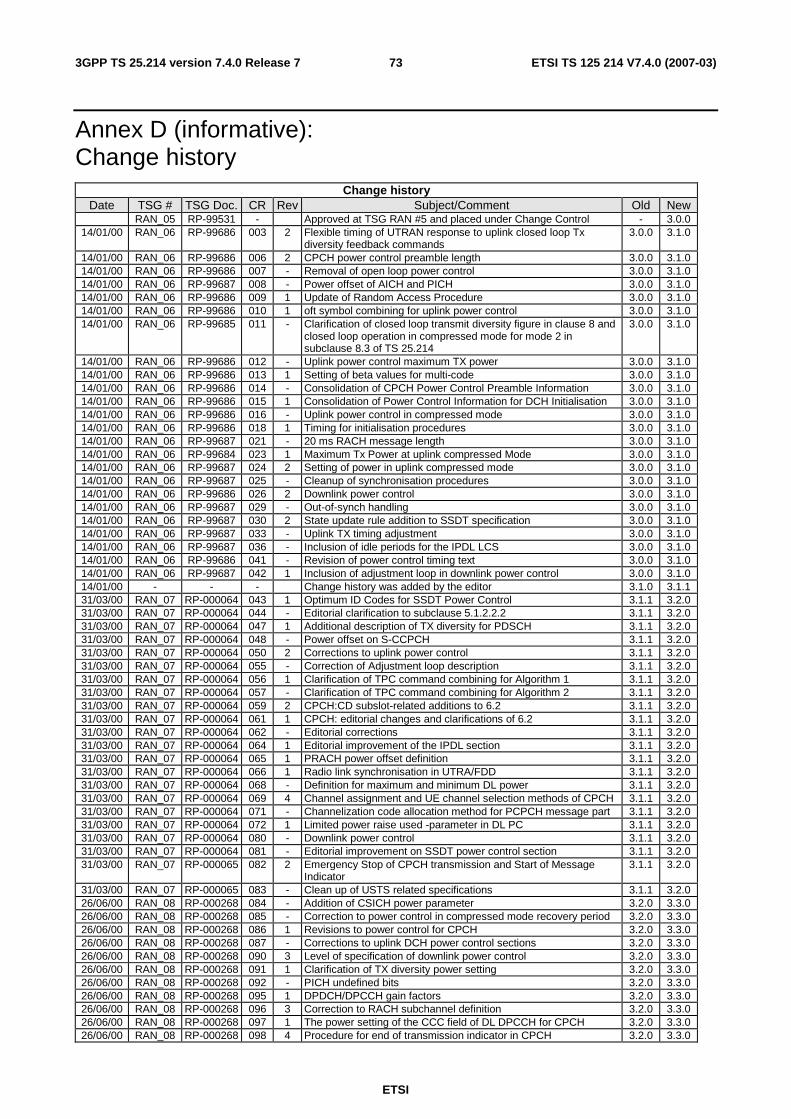
ETSI
ETSI TS 125 214 V7.4.0 (2007-03) 733GPP TS 25.214 version 7.4.0 Release 7
Annex D (informative): Change history
Change history Date TSG # TSG Doc. CR Rev Subject/Comment Old New
RAN_05 RP-99531 - Approved at TSG RAN #5 and placed under Change Control - 3.0.0 14/01/00 RAN_06 RP-99686 003 2 Flexible timing of UTRAN response to uplink closed loop Tx
diversity feedback commands 3.0.0 3.1.0
14/01/00 RAN_06 RP-99686 006 2 CPCH power control preamble length 3.0.0 3.1.0 14/01/00 RAN_06 RP-99686 007 - Removal of open loop power control 3.0.0 3.1.0 14/01/00 RAN_06 RP-99687 008 - Power offset of AICH and PICH 3.0.0 3.1.0 14/01/00 RAN_06 RP-99686 009 1 Update of Random Access Procedure 3.0.0 3.1.0 14/01/00 RAN_06 RP-99686 010 1 oft symbol combining for uplink power control 3.0.0 3.1.0 14/01/00 RAN_06 RP-99685 011 - Clarification of closed loop transmit diversity figure in clause 8 and
closed loop operation in compressed mode for mode 2 in subclause 8.3 of TS 25.214
3.0.0 3.1.0
14/01/00 RAN_06 RP-99686 012 - Uplink power control maximum TX power 3.0.0 3.1.0 14/01/00 RAN_06 RP-99686 013 1 Setting of beta values for multi-code 3.0.0 3.1.0 14/01/00 RAN_06 RP-99686 014 - Consolidation of CPCH Power Control Preamble Information 3.0.0 3.1.0 14/01/00 RAN_06 RP-99686 015 1 Consolidation of Power Control Information for DCH Initialisation 3.0.0 3.1.0 14/01/00 RAN_06 RP-99686 016 - Uplink power control in compressed mode 3.0.0 3.1.0 14/01/00 RAN_06 RP-99686 018 1 Timing for initialisation procedures 3.0.0 3.1.0 14/01/00 RAN_06 RP-99687 021 - 20 ms RACH message length 3.0.0 3.1.0 14/01/00 RAN_06 RP-99684 023 1 Maximum Tx Power at uplink compressed Mode 3.0.0 3.1.0 14/01/00 RAN_06 RP-99687 024 2 Setting of power in uplink compressed mode 3.0.0 3.1.0 14/01/00 RAN_06 RP-99687 025 - Cleanup of synchronisation procedures 3.0.0 3.1.0 14/01/00 RAN_06 RP-99686 026 2 Downlink power control 3.0.0 3.1.0 14/01/00 RAN_06 RP-99687 029 - Out-of-synch handling 3.0.0 3.1.0 14/01/00 RAN_06 RP-99687 030 2 State update rule addition to SSDT specification 3.0.0 3.1.0 14/01/00 RAN_06 RP-99687 033 - Uplink TX timing adjustment 3.0.0 3.1.0 14/01/00 RAN_06 RP-99687 036 - Inclusion of idle periods for the IPDL LCS 3.0.0 3.1.0 14/01/00 RAN_06 RP-99686 041 - Revision of power control timing text 3.0.0 3.1.0 14/01/00 RAN_06 RP-99687 042 1 Inclusion of adjustment loop in downlink power control 3.0.0 3.1.0 14/01/00 - - - Change history was added by the editor 3.1.0 3.1.1 31/03/00 RAN_07 RP-000064 043 1 Optimum ID Codes for SSDT Power Control 3.1.1 3.2.0 31/03/00 RAN_07 RP-000064 044 - Editorial clarification to subclause 5.1.2.2.2 3.1.1 3.2.0 31/03/00 RAN_07 RP-000064 047 1 Additional description of TX diversity for PDSCH 3.1.1 3.2.0 31/03/00 RAN_07 RP-000064 048 - Power offset on S-CCPCH 3.1.1 3.2.0 31/03/00 RAN_07 RP-000064 050 2 Corrections to uplink power control 3.1.1 3.2.0 31/03/00 RAN_07 RP-000064 055 - Correction of Adjustment loop description 3.1.1 3.2.0 31/03/00 RAN_07 RP-000064 056 1 Clarification of TPC command combining for Algorithm 1 3.1.1 3.2.0 31/03/00 RAN_07 RP-000064 057 - Clarification of TPC command combining for Algorithm 2 3.1.1 3.2.0 31/03/00 RAN_07 RP-000064 059 2 CPCH:CD subslot-related additions to 6.2 3.1.1 3.2.0 31/03/00 RAN_07 RP-000064 061 1 CPCH: editorial changes and clarifications of 6.2 3.1.1 3.2.0 31/03/00 RAN_07 RP-000064 062 - Editorial corrections 3.1.1 3.2.0 31/03/00 RAN_07 RP-000064 064 1 Editorial improvement of the IPDL section 3.1.1 3.2.0 31/03/00 RAN_07 RP-000064 065 1 PRACH power offset definition 3.1.1 3.2.0 31/03/00 RAN_07 RP-000064 066 1 Radio link synchronisation in UTRA/FDD 3.1.1 3.2.0 31/03/00 RAN_07 RP-000064 068 - Definition for maximum and minimum DL power 3.1.1 3.2.0 31/03/00 RAN_07 RP-000064 069 4 Channel assignment and UE channel selection methods of CPCH 3.1.1 3.2.0 31/03/00 RAN_07 RP-000064 071 - Channelization code allocation method for PCPCH message part 3.1.1 3.2.0 31/03/00 RAN_07 RP-000064 072 1 Limited power raise used -parameter in DL PC 3.1.1 3.2.0 31/03/00 RAN_07 RP-000064 080 - Downlink power control 3.1.1 3.2.0 31/03/00 RAN_07 RP-000064 081 - Editorial improvement on SSDT power control section 3.1.1 3.2.0 31/03/00 RAN_07 RP-000065 082 2 Emergency Stop of CPCH transmission and Start of Message
Indicator 3.1.1 3.2.0
31/03/00 RAN_07 RP-000065 083 - Clean up of USTS related specifications 3.1.1 3.2.0 26/06/00 RAN_08 RP-000268 084 - Addition of CSICH power parameter 3.2.0 3.3.0 26/06/00 RAN_08 RP-000268 085 - Correction to power control in compressed mode recovery period 3.2.0 3.3.0 26/06/00 RAN_08 RP-000268 086 1 Revisions to power control for CPCH 3.2.0 3.3.0 26/06/00 RAN_08 RP-000268 087 - Corrections to uplink DCH power control sections 3.2.0 3.3.0 26/06/00 RAN_08 RP-000268 090 3 Level of specification of downlink power control 3.2.0 3.3.0 26/06/00 RAN_08 RP-000268 091 1 Clarification of TX diversity power setting 3.2.0 3.3.0 26/06/00 RAN_08 RP-000268 092 - PICH undefined bits 3.2.0 3.3.0 26/06/00 RAN_08 RP-000268 095 1 DPDCH/DPCCH gain factors 3.2.0 3.3.0 26/06/00 RAN_08 RP-000268 096 3 Correction to RACH subchannel definition 3.2.0 3.3.0 26/06/00 RAN_08 RP-000268 097 1 The power setting of the CCC field of DL DPCCH for CPCH 3.2.0 3.3.0 26/06/00 RAN_08 RP-000268 098 4 Procedure for end of transmission indicator in CPCH 3.2.0 3.3.0
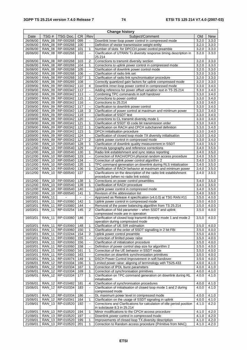
ETSI
ETSI TS 125 214 V7.4.0 (2007-03) 743GPP TS 25.214 version 7.4.0 Release 7
Change history Date TSG # TSG Doc. CR Rev Subject/Comment Old New
26/06/00 RAN_08 RP-000268 099 - Downlink inner-loop power control in compressed mode 3.2.0 3.3.0 26/06/00 RAN_08 RP-000268 100 - Definition of vector transmission weight entity 3.2.0 3.3.0 26/06/00 RAN_08 RP-000268 101 1 Number of slots for DPCCH power control preamble 3.2.0 3.3.0 26/06/00 RAN_08 RP-000268 102 - Clarification of UTRAN Tx diversity response timing description in
25.214 3.2.0 3.3.0
26/06/00 RAN_08 RP-000268 103 2 Corrections to transmit diversity section 3.2.0 3.3.0 26/06/00 RAN_08 RP-000268 104 1 Corrections to uplink power control in compressed mode 3.2.0 3.3.0 26/06/00 RAN_08 RP-000268 105 - Clarification of downlink power control mode 3.2.0 3.3.0 26/06/00 RAN_08 RP-000268 106 - Clarification of radio link set 3.2.0 3.3.0 26/06/00 RAN_08 RP-000268 107 1 Clarification of radio link synchronisation procedure 3.2.0 3.3.0 26/06/00 RAN_08 RP-000269 108 - Correctly quantized gain factors for uplink compressed mode 3.2.0 3.3.0 23/09/00 RAN_09 RP-000342 110 4 Downlink inner-loop power control in compressed mode 3.3.0 3.4.0 23/09/00 RAN_09 RP-000342 112 - Adding reference for power offset variation text in TS 25.214 3.3.0 3.4.0 23/09/00 RAN_09 RP-000342 113 - Combining TPC commands in soft handover 3.3.0 3.4.0 23/09/00 RAN_09 RP-000342 115 1 Corrections to power control 3.3.0 3.4.0 23/09/00 RAN_09 RP-000342 116 - Corrections to 25.214 3.3.0 3.4.0 23/09/00 RAN_09 RP-000342 117 - Clarification to downlink power control 3.3.0 3.4.0 23/09/00 RAN_09 RP-000342 118 3 Clarification of power control at maximum and minimum power 3.3.0 3.4.0 23/09/00 RAN_09 RP-000342 119 - Clarification of SSDT text 3.3.0 3.4.0 23/09/00 RAN_09 RP-000342 120 - Corrections to CL transmit diversity mode 1 3.3.0 3.4.0 23/09/00 RAN_09 RP-000342 121 1 Clarification of SSDT ID code bit transmission order 3.3.0 3.4.0 23/09/00 RAN_09 RP-000342 122 1 Clarification on RACH and CPCH subchannel definition 3.3.0 3.4.0 23/09/00 RAN_09 RP-000342 123 1 DPCH initialisation procedure 3.3.0 3.4.0 23/09/00 RAN_09 RP-000342 124 - Clarification of closed loop mode TX diversity initialisation 3.3.0 3.4.0 23/09/00 RAN_09 RP-000342 127 2 Uplink power control in compressed mode 3.3.0 3.4.0 15/12/00 RAN_10 RP-000540 128 1 Clarification of downlink quality measurement in SSDT 3.4.0 3.5.0 15/12/00 RAN_10 RP-000540 129 - Formula typography and reference corrections 3.4.0 3.5.0 15/12/00 RAN_10 RP-000540 130 1 Radio link establishment and sync status reporting 3.4.0 3.5.0 15/12/00 RAN_10 RP-000540 133 - Correction of RACH/CPCH physical random access procedure 3.4.0 3.5.0 15/12/00 RAN_10 RP-000540 134 - Correction of uplink power control algorithm 2 3.4.0 3.5.0 15/12/00 RAN_10 RP-000540 135 1 TPC command generation on downlink during RLS initialization 3.4.0 3.5.0 15/12/00 RAN_10 RP-000540 136 1 Clarification of RACH behavior at maximum and minimum power 3.4.0 3.5.0 15/12/00 RAN_10 RP-000540 137 - Clarifications on the description of the radio link establishment
procedure (when no radio link exists) 3.4.0 3.5.0
15/12/00 RAN_10 RP-000540 138 1 Corrections on power control preambles 3.4.0 3.5.0 15/12/00 RAN_10 RP-000540 139 1 Clarification of RACH procedure 3.4.0 3.5.0 15/12/00 RAN_10 RP-000540 140 - Uplink power control in compressed mode 3.4.0 3.5.0 15/12/00 RAN_10 RP-000540 141 1 Revision of the abbreviation list 3.4.0 3.5.0 16/03/01 RAN_11 - - - Approved as Release 4 specification (v4.0.0) at TSG RAN #11 3.5.0 4.0.0 16/03/01 RAN_11 RP-010060 142 1 Uplink power control in compressed mode 3.5.0 4.0.0 16/03/01 RAN_11 RP-010060 144 - Removal of the power balancing algorithm from TS 25.214 3.5.0 4.0.0 16/03/01 RAN_11 RP-010254 145 2 Clarification of Nid parameter – when SSDT and uplink
compressed mode are in operation 3.5.0 4.0.0
16/03/01 RAN_11 RP-010060 146 - Clarification of closed loop transmit diversity mode 1 and mode 2 operation during compressed mode
3.5.0 4.0.0
16/03/01 RAN_11 RP-010060 148 1 Clarification of UE SIR estimation 3.5.0 4.0.0 16/03/01 RAN_11 RP-010060 150 1 Clarification of the order of SSDT signalling in 2 bit FBI 3.5.0 4.0.0 16/03/01 RAN_11 RP-010244 154 2 Uplink power control preamble 3.5.0 4.0.0 16/03/01 RAN_11 RP-010060 155 - Correction of limited power raise 3.5.0 4.0.0 16/03/01 RAN_11 RP-010060 156 - Clarification of initialization procedure 3.5.0 4.0.0 16/03/01 RAN_11 RP-010060 158 - Definition of power control step size for algorithm 2 3.5.0 4.0.0 16/03/01 RAN_11 RP-010060 161 1 Correction of the UE behavior in SSDT mode 3.5.0 4.0.0 16/03/01 RAN_11 RP-010060 163 - Correction on downlink synchronization primitives 3.5.0 4.0.0 16/03/01 RAN_11 RP-010074 149 1 DSCH Power Control Improvement in soft handover 3.5.0 4.0.0 15/06/01 RAN_12 RP-010334 166 1 Limited power raise: aligning of terminology with TS25.433 4.0.0 4.1.0 15/06/01 RAN_12 RP-010334 167 1 Correction of IPDL burst parameters 4.0.0 4.1.0 15/06/01 RAN_12 RP-010334 169 1 Correction of synchronisation primitives 4.0.0 4.1.0 15/06/01 RAN_12 RP-010334 177 1 Clarification on TPC command generation on downlink during RL
initialisation 4.0.0 4.1.0
15/06/01 RAN_12 RP-010482 181 4 Clarification of synchronisation procedures 4.0.0 4.1.0 15/06/01 RAN_12 RP-010334 183 - Clarification of initialisation of closed loop mode 1 and 2 during
compressed mode 4.0.0 4.1.0
15/06/01 RAN_12 RP-010334 186 - DL maximum power level in compressed mode 4.0.0 4.1.0 15/06/01 RAN_12 RP-010341 164 1 Clarification on the usage of SSDT signaling in uplink 4.0.0 4.1.0 21/09/01 RAN_13 RP-010520 192 - Corrections and Clarifications for calculation of idle period position
in subclause 8.3 in 25.214 4.1.0 4.2.0
21/09/01 RAN_13 RP-010520 194 1 Minor modifications to the CPCH access procedure 4.1.0 4.2.0 21/09/01 RAN_13 RP-010520 197 - Downlink power control in compressed mode 4.1.0 4.2.0 21/09/01 RAN_13 RP-010520 199 1 Improvements of closed loop TX diversity description 4.1.0 4.2.0 21/09/01 RAN_13 RP-010520 201 1 Correction to Random access procedure (Primitive from MAC) 4.1.0 4.2.0
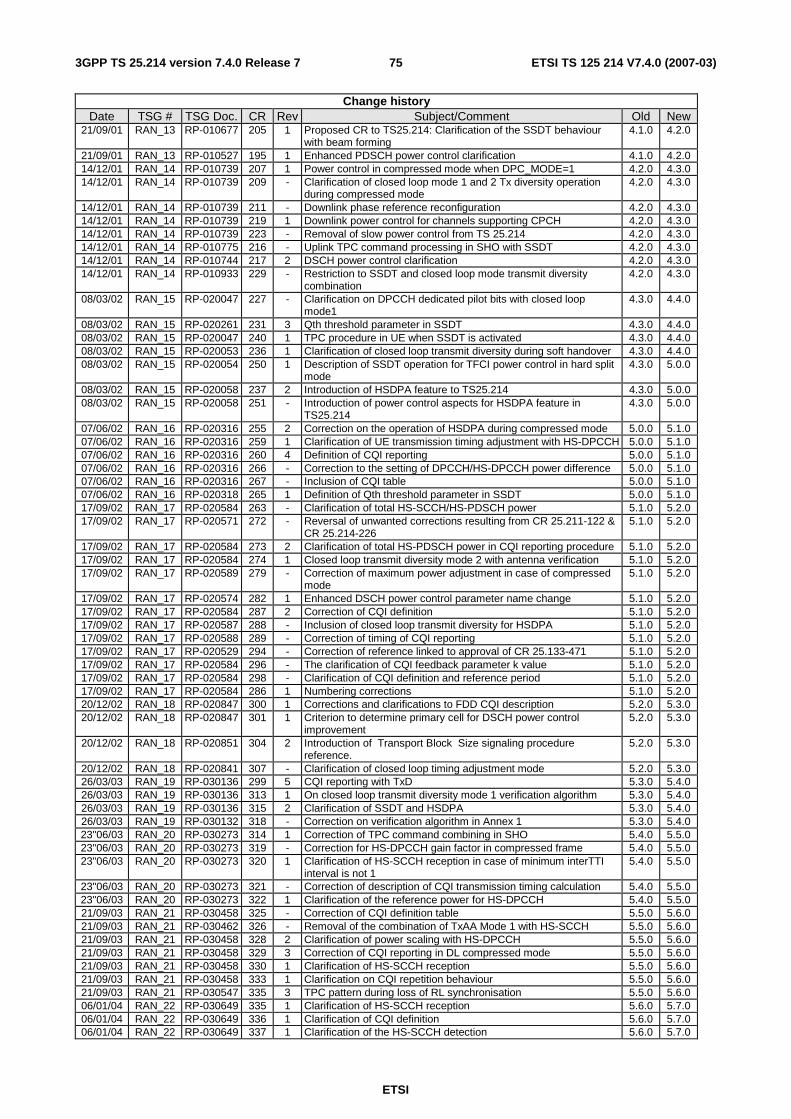
ETSI
ETSI TS 125 214 V7.4.0 (2007-03) 753GPP TS 25.214 version 7.4.0 Release 7
Change history Date TSG # TSG Doc. CR Rev Subject/Comment Old New
21/09/01 RAN_13 RP-010677 205 1 Proposed CR to TS25.214: Clarification of the SSDT behaviour with beam forming
4.1.0 4.2.0
21/09/01 RAN_13 RP-010527 195 1 Enhanced PDSCH power control clarification 4.1.0 4.2.0 14/12/01 RAN_14 RP-010739 207 1 Power control in compressed mode when DPC_MODE=1 4.2.0 4.3.0 14/12/01 RAN_14 RP-010739 209 - Clarification of closed loop mode 1 and 2 Tx diversity operation
during compressed mode 4.2.0 4.3.0
14/12/01 RAN_14 RP-010739 211 - Downlink phase reference reconfiguration 4.2.0 4.3.0 14/12/01 RAN_14 RP-010739 219 1 Downlink power control for channels supporting CPCH 4.2.0 4.3.0 14/12/01 RAN_14 RP-010739 223 - Removal of slow power control from TS 25.214 4.2.0 4.3.0 14/12/01 RAN_14 RP-010775 216 - Uplink TPC command processing in SHO with SSDT 4.2.0 4.3.0 14/12/01 RAN_14 RP-010744 217 2 DSCH power control clarification 4.2.0 4.3.0 14/12/01 RAN_14 RP-010933 229 - Restriction to SSDT and closed loop mode transmit diversity
combination 4.2.0 4.3.0
08/03/02 RAN_15 RP-020047 227 - Clarification on DPCCH dedicated pilot bits with closed loop mode1
4.3.0 4.4.0
08/03/02 RAN_15 RP-020261 231 3 Qth threshold parameter in SSDT 4.3.0 4.4.0 08/03/02 RAN_15 RP-020047 240 1 TPC procedure in UE when SSDT is activated 4.3.0 4.4.0 08/03/02 RAN_15 RP-020053 236 1 Clarification of closed loop transmit diversity during soft handover 4.3.0 4.4.0 08/03/02 RAN_15 RP-020054 250 1 Description of SSDT operation for TFCI power control in hard split
mode 4.3.0 5.0.0
08/03/02 RAN_15 RP-020058 237 2 Introduction of HSDPA feature to TS25.214 4.3.0 5.0.0 08/03/02 RAN_15 RP-020058 251 - Introduction of power control aspects for HSDPA feature in
TS25.214 4.3.0 5.0.0
07/06/02 RAN_16 RP-020316 255 2 Correction on the operation of HSDPA during compressed mode 5.0.0 5.1.0 07/06/02 RAN_16 RP-020316 259 1 Clarification of UE transmission timing adjustment with HS-DPCCH 5.0.0 5.1.0 07/06/02 RAN_16 RP-020316 260 4 Definition of CQI reporting 5.0.0 5.1.0 07/06/02 RAN_16 RP-020316 266 - Correction to the setting of DPCCH/HS-DPCCH power difference 5.0.0 5.1.0 07/06/02 RAN_16 RP-020316 267 - Inclusion of CQI table 5.0.0 5.1.0 07/06/02 RAN_16 RP-020318 265 1 Definition of Qth threshold parameter in SSDT 5.0.0 5.1.0 17/09/02 RAN_17 RP-020584 263 - Clarification of total HS-SCCH/HS-PDSCH power 5.1.0 5.2.0 17/09/02 RAN_17 RP-020571 272 - Reversal of unwanted corrections resulting from CR 25.211-122 &
CR 25.214-226 5.1.0 5.2.0
17/09/02 RAN_17 RP-020584 273 2 Clarification of total HS-PDSCH power in CQI reporting procedure 5.1.0 5.2.0 17/09/02 RAN_17 RP-020584 274 1 Closed loop transmit diversity mode 2 with antenna verification 5.1.0 5.2.0 17/09/02 RAN_17 RP-020589 279 - Correction of maximum power adjustment in case of compressed
mode 5.1.0 5.2.0
17/09/02 RAN_17 RP-020574 282 1 Enhanced DSCH power control parameter name change 5.1.0 5.2.0 17/09/02 RAN_17 RP-020584 287 2 Correction of CQI definition 5.1.0 5.2.0 17/09/02 RAN_17 RP-020587 288 - Inclusion of closed loop transmit diversity for HSDPA 5.1.0 5.2.0 17/09/02 RAN_17 RP-020588 289 - Correction of timing of CQI reporting 5.1.0 5.2.0 17/09/02 RAN_17 RP-020529 294 - Correction of reference linked to approval of CR 25.133-471 5.1.0 5.2.0 17/09/02 RAN_17 RP-020584 296 - The clarification of CQI feedback parameter k value 5.1.0 5.2.0 17/09/02 RAN_17 RP-020584 298 - Clarification of CQI definition and reference period 5.1.0 5.2.0 17/09/02 RAN_17 RP-020584 286 1 Numbering corrections 5.1.0 5.2.0 20/12/02 RAN_18 RP-020847 300 1 Corrections and clarifications to FDD CQI description 5.2.0 5.3.0 20/12/02 RAN_18 RP-020847 301 1 Criterion to determine primary cell for DSCH power control
improvement 5.2.0 5.3.0
20/12/02 RAN_18 RP-020851 304 2 Introduction of Transport Block Size signaling procedure reference.
5.2.0 5.3.0
20/12/02 RAN_18 RP-020841 307 - Clarification of closed loop timing adjustment mode 5.2.0 5.3.0 26/03/03 RAN_19 RP-030136 299 5 CQI reporting with TxD 5.3.0 5.4.0 26/03/03 RAN_19 RP-030136 313 1 On closed loop transmit diversity mode 1 verification algorithm 5.3.0 5.4.0 26/03/03 RAN_19 RP-030136 315 2 Clarification of SSDT and HSDPA 5.3.0 5.4.0 26/03/03 RAN_19 RP-030132 318 - Correction on verification algorithm in Annex 1 5.3.0 5.4.0 23"06/03 RAN_20 RP-030273 314 1 Correction of TPC command combining in SHO 5.4.0 5.5.0 23"06/03 RAN_20 RP-030273 319 - Correction for HS-DPCCH gain factor in compressed frame 5.4.0 5.5.0 23"06/03 RAN_20 RP-030273 320 1 Clarification of HS-SCCH reception in case of minimum interTTI
interval is not 1 5.4.0 5.5.0
23"06/03 RAN_20 RP-030273 321 - Correction of description of CQI transmission timing calculation 5.4.0 5.5.0 23"06/03 RAN_20 RP-030273 322 1 Clarification of the reference power for HS-DPCCH 5.4.0 5.5.0 21/09/03 RAN_21 RP-030458 325 - Correction of CQI definition table 5.5.0 5.6.0 21/09/03 RAN_21 RP-030462 326 - Removal of the combination of TxAA Mode 1 with HS-SCCH 5.5.0 5.6.0 21/09/03 RAN_21 RP-030458 328 2 Clarification of power scaling with HS-DPCCH 5.5.0 5.6.0 21/09/03 RAN_21 RP-030458 329 3 Correction of CQI reporting in DL compressed mode 5.5.0 5.6.0 21/09/03 RAN_21 RP-030458 330 1 Clarification of HS-SCCH reception 5.5.0 5.6.0 21/09/03 RAN_21 RP-030458 333 1 Clarification on CQI repetition behaviour 5.5.0 5.6.0 21/09/03 RAN_21 RP-030547 335 3 TPC pattern during loss of RL synchronisation 5.5.0 5.6.0 06/01/04 RAN_22 RP-030649 335 1 Clarification of HS-SCCH reception 5.6.0 5.7.0 06/01/04 RAN_22 RP-030649 336 1 Clarification of CQI definition 5.6.0 5.7.0 06/01/04 RAN_22 RP-030649 337 1 Clarification of the HS-SCCH detection 5.6.0 5.7.0
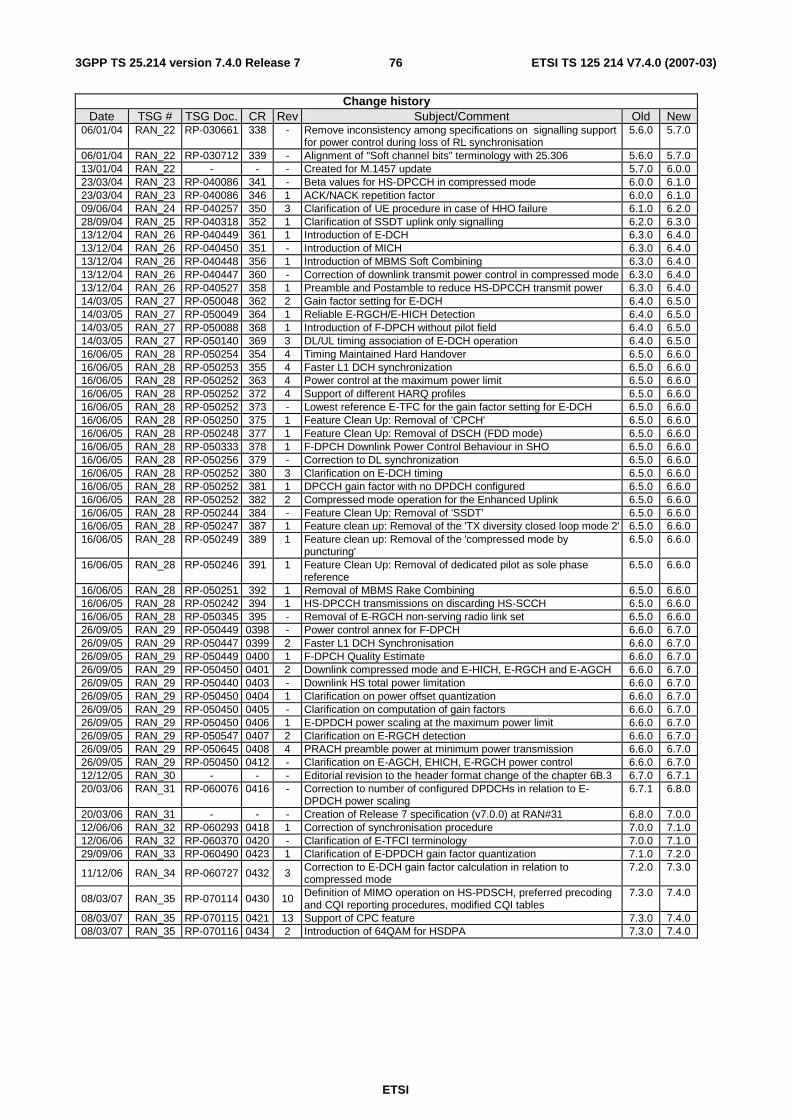
ETSI
ETSI TS 125 214 V7.4.0 (2007-03) 763GPP TS 25.214 version 7.4.0 Release 7
Change history Date TSG # TSG Doc. CR Rev Subject/Comment Old New
06/01/04 RAN_22 RP-030661 338 - Remove inconsistency among specifications on signalling support for power control during loss of RL synchronisation
5.6.0 5.7.0
06/01/04 RAN_22 RP-030712 339 - Alignment of "Soft channel bits" terminology with 25.306 5.6.0 5.7.0 13/01/04 RAN_22 - - - Created for M.1457 update 5.7.0 6.0.0 23/03/04 RAN_23 RP-040086 341 - Beta values for HS-DPCCH in compressed mode 6.0.0 6.1.0 23/03/04 RAN_23 RP-040086 346 1 ACK/NACK repetition factor 6.0.0 6.1.0 09/06/04 RAN_24 RP-040257 350 3 Clarification of UE procedure in case of HHO failure 6.1.0 6.2.0 28/09/04 RAN_25 RP-040318 352 1 Clarification of SSDT uplink only signalling 6.2.0 6.3.0 13/12/04 RAN_26 RP-040449 361 1 Introduction of E-DCH 6.3.0 6.4.0 13/12/04 RAN_26 RP-040450 351 - Introduction of MICH 6.3.0 6.4.0 13/12/04 RAN_26 RP-040448 356 1 Introduction of MBMS Soft Combining 6.3.0 6.4.0 13/12/04 RAN_26 RP-040447 360 - Correction of downlink transmit power control in compressed mode 6.3.0 6.4.0 13/12/04 RAN_26 RP-040527 358 1 Preamble and Postamble to reduce HS-DPCCH transmit power 6.3.0 6.4.0 14/03/05 RAN_27 RP-050048 362 2 Gain factor setting for E-DCH 6.4.0 6.5.0 14/03/05 RAN_27 RP-050049 364 1 Reliable E-RGCH/E-HICH Detection 6.4.0 6.5.0 14/03/05 RAN_27 RP-050088 368 1 Introduction of F-DPCH without pilot field 6.4.0 6.5.0 14/03/05 RAN_27 RP-050140 369 3 DL/UL timing association of E-DCH operation 6.4.0 6.5.0 16/06/05 RAN_28 RP-050254 354 4 Timing Maintained Hard Handover 6.5.0 6.6.0 16/06/05 RAN_28 RP-050253 355 4 Faster L1 DCH synchronization 6.5.0 6.6.0 16/06/05 RAN_28 RP-050252 363 4 Power control at the maximum power limit 6.5.0 6.6.0 16/06/05 RAN_28 RP-050252 372 4 Support of different HARQ profiles 6.5.0 6.6.0 16/06/05 RAN_28 RP-050252 373 - Lowest reference E-TFC for the gain factor setting for E-DCH 6.5.0 6.6.0 16/06/05 RAN_28 RP-050250 375 1 Feature Clean Up: Removal of 'CPCH' 6.5.0 6.6.0 16/06/05 RAN_28 RP-050248 377 1 Feature Clean Up: Removal of DSCH (FDD mode) 6.5.0 6.6.0 16/06/05 RAN_28 RP-050333 378 1 F-DPCH Downlink Power Control Behaviour in SHO 6.5.0 6.6.0 16/06/05 RAN_28 RP-050256 379 - Correction to DL synchronization 6.5.0 6.6.0 16/06/05 RAN_28 RP-050252 380 3 Clarification on E-DCH timing 6.5.0 6.6.0 16/06/05 RAN_28 RP-050252 381 1 DPCCH gain factor with no DPDCH configured 6.5.0 6.6.0 16/06/05 RAN_28 RP-050252 382 2 Compressed mode operation for the Enhanced Uplink 6.5.0 6.6.0 16/06/05 RAN_28 RP-050244 384 - Feature Clean Up: Removal of 'SSDT' 6.5.0 6.6.0 16/06/05 RAN_28 RP-050247 387 1 Feature clean up: Removal of the 'TX diversity closed loop mode 2' 6.5.0 6.6.0 16/06/05 RAN_28 RP-050249 389 1 Feature clean up: Removal of the 'compressed mode by
puncturing' 6.5.0 6.6.0
16/06/05 RAN_28 RP-050246 391 1 Feature Clean Up: Removal of dedicated pilot as sole phase reference
6.5.0 6.6.0
16/06/05 RAN_28 RP-050251 392 1 Removal of MBMS Rake Combining 6.5.0 6.6.0 16/06/05 RAN_28 RP-050242 394 1 HS-DPCCH transmissions on discarding HS-SCCH 6.5.0 6.6.0 16/06/05 RAN_28 RP-050345 395 - Removal of E-RGCH non-serving radio link set 6.5.0 6.6.0 26/09/05 RAN_29 RP-050449 0398 - Power control annex for F-DPCH 6.6.0 6.7.0 26/09/05 RAN_29 RP-050447 0399 2 Faster L1 DCH Synchronisation 6.6.0 6.7.0 26/09/05 RAN_29 RP-050449 0400 1 F-DPCH Quality Estimate 6.6.0 6.7.0 26/09/05 RAN_29 RP-050450 0401 2 Downlink compressed mode and E-HICH, E-RGCH and E-AGCH 6.6.0 6.7.0 26/09/05 RAN_29 RP-050440 0403 - Downlink HS total power limitation 6.6.0 6.7.0 26/09/05 RAN_29 RP-050450 0404 1 Clarification on power offset quantization 6.6.0 6.7.0 26/09/05 RAN_29 RP-050450 0405 - Clarification on computation of gain factors 6.6.0 6.7.0 26/09/05 RAN_29 RP-050450 0406 1 E-DPDCH power scaling at the maximum power limit 6.6.0 6.7.0 26/09/05 RAN_29 RP-050547 0407 2 Clarification on E-RGCH detection 6.6.0 6.7.0 26/09/05 RAN_29 RP-050645 0408 4 PRACH preamble power at minimum power transmission 6.6.0 6.7.0 26/09/05 RAN_29 RP-050450 0412 - Clarification on E-AGCH, EHICH, E-RGCH power control 6.6.0 6.7.0 12/12/05 RAN_30 - - - Editorial revision to the header format change of the chapter 6B.3 6.7.0 6.7.1 20/03/06 RAN_31 RP-060076 0416 - Correction to number of configured DPDCHs in relation to E-
DPDCH power scaling 6.7.1 6.8.0
20/03/06 RAN_31 - - - Creation of Release 7 specification (v7.0.0) at RAN#31 6.8.0 7.0.0 12/06/06 RAN_32 RP-060293 0418 1 Correction of synchronisation procedure 7.0.0 7.1.0 12/06/06 RAN_32 RP-060370 0420 - Clarification of E-TFCI terminology 7.0.0 7.1.0 29/09/06 RAN_33 RP-060490 0423 1 Clarification of E-DPDCH gain factor quantization 7.1.0 7.2.0
11/12/06 RAN_34 RP-060727 0432 3 Correction to E-DCH gain factor calculation in relation to compressed mode
7.2.0 7.3.0
08/03/07 RAN_35 RP-070114 0430 10 Definition of MIMO operation on HS-PDSCH, preferred precoding and CQI reporting procedures, modified CQI tables
7.3.0 7.4.0
08/03/07 RAN_35 RP-070115 0421 13 Support of CPC feature 7.3.0 7.4.0 08/03/07 RAN_35 RP-070116 0434 2 Introduction of 64QAM for HSDPA 7.3.0 7.4.0
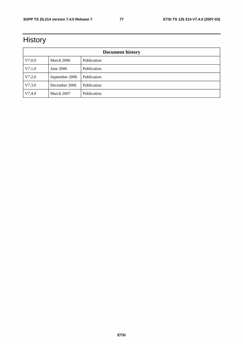
ETSI
ETSI TS 125 214 V7.4.0 (2007-03) 773GPP TS 25.214 version 7.4.0 Release 7
History
Document history
V7.0.0 March 2006 Publication
V7.1.0 June 2006 Publication
V7.2.0 September 2006 Publication
V7.3.0 December 2006 Publication
V7.4.0 March 2007 Publication