Embed Size (px)
Citation preview
ETSI TS 125 211 V8.7.0 (2010-10)
Technical Specification
Universal Mobile Telecommunications System (UMTS);Physical channels and mapping of transport
channels onto physical channels (FDD) (3GPP TS 25.211 version 8.7.0 Release 8)
ETSI
ETSI TS 125 211 V8.7.0 (2010-10)13GPP TS 25.211 version 8.7.0 Release 8
Reference RTS/TSGR-0125211v870
Keywords UMTS
ETSI
650 Route des Lucioles F-06921 Sophia Antipolis Cedex - FRANCE
Tel.: +33 4 92 94 42 00 Fax: +33 4 93 65 47 16
Siret N° 348 623 562 00017 - NAF 742 C
Association à but non lucratif enregistrée à la Sous-Préfecture de Grasse (06) N° 7803/88
Important notice
Individual copies of the present document can be downloaded from: http://www.etsi.org
The present document may be made available in more than one electronic version or in print. In any case of existing or perceived difference in contents between such versions, the reference version is the Portable Document Format (PDF).
In case of dispute, the reference shall be the printing on ETSI printers of the PDF version kept on a specific network drive within ETSI Secretariat.
Users of the present document should be aware that the document may be subject to revision or change of status. Information on the current status of this and other ETSI documents is available at
http://portal.etsi.org/tb/status/status.asp
If you find errors in the present document, please send your comment to one of the following services: http://portal.etsi.org/chaircor/ETSI_support.asp
Copyright Notification
No part may be reproduced except as authorized by written permission. The copyright and the foregoing restriction extend to reproduction in all media.
© European Telecommunications Standards Institute 2010.
All rights reserved.
DECTTM, PLUGTESTSTM, UMTSTM, TIPHONTM, the TIPHON logo and the ETSI logo are Trade Marks of ETSI registered for the benefit of its Members.
3GPPTM is a Trade Mark of ETSI registered for the benefit of its Members and of the 3GPP Organizational Partners. LTE™ is a Trade Mark of ETSI currently being registered
for the benefit of its Members and of the 3GPP Organizational Partners. GSM® and the GSM logo are Trade Marks registered and owned by the GSM Association.
ETSI
ETSI TS 125 211 V8.7.0 (2010-10)23GPP TS 25.211 version 8.7.0 Release 8
Intellectual Property Rights IPRs essential or potentially essential to the present document may have been declared to ETSI. The information pertaining to these essential IPRs, if any, is publicly available for ETSI members and non-members, and can be found in ETSI SR 000 314: "Intellectual Property Rights (IPRs); Essential, or potentially Essential, IPRs notified to ETSI in respect of ETSI standards", which is available from the ETSI Secretariat. Latest updates are available on the ETSI Web server (http://webapp.etsi.org/IPR/home.asp).
Pursuant to the ETSI IPR Policy, no investigation, including IPR searches, has been carried out by ETSI. No guarantee can be given as to the existence of other IPRs not referenced in ETSI SR 000 314 (or the updates on the ETSI Web server) which are, or may be, or may become, essential to the present document.
Foreword This Technical Specification (TS) has been produced by ETSI 3rd Generation Partnership Project (3GPP).
The present document may refer to technical specifications or reports using their 3GPP identities, UMTS identities or GSM identities. These should be interpreted as being references to the corresponding ETSI deliverables.
The cross reference between GSM, UMTS, 3GPP and ETSI identities can be found under http://webapp.etsi.org/key/queryform.asp.
ETSI
ETSI TS 125 211 V8.7.0 (2010-10)33GPP TS 25.211 version 8.7.0 Release 8
Contents
Intellectual Property Rights ................................................................................................................................ 2
Foreword ............................................................................................................................................................. 2
Foreword ............................................................................................................................................................. 5
1 Scope ........................................................................................................................................................ 6
2 References ................................................................................................................................................ 6
3 Symbols and abbreviations ....................................................................................................................... 7
3.1 Symbols .............................................................................................................................................................. 7
3.2 Abbreviations ..................................................................................................................................................... 7
4 Services offered to higher layers .............................................................................................................. 8
4.1 Transport channels ............................................................................................................................................. 8
4.1.1 Dedicated transport channels ........................................................................................................................ 8
4.1.1.1 DCH - Dedicated Channel ...................................................................................................................... 8
4.1.1.2 E-DCH – Enhanced Dedicated Channel ................................................................................................. 8
4.1.2 Common transport channels ......................................................................................................................... 8
4.1.2.1 BCH - Broadcast Channel ....................................................................................................................... 8
4.1.2.2 FACH - Forward Access Channel ........................................................................................................... 8
4.1.2.3 PCH - Paging Channel ............................................................................................................................ 8
4.1.2.4 RACH - Random Access Channel .......................................................................................................... 9
4.1.2.5 Void......................................................................................................................................................... 9
4.1.2.6 Void......................................................................................................................................................... 9
4.1.2.7 HS-DSCH – High Speed Downlink Shared Channel .............................................................................. 9
4.1.2.7A E-DCH - Enhanced Dedicated Channel .................................................................................................. 9
4.2 Indicators ............................................................................................................................................................ 9
5 Physical channels and physical signals .................................................................................................... 9
5.1 Physical signals ................................................................................................................................................ 10
5.2 Uplink physical channels .................................................................................................................................. 10
5.2.1 Dedicated uplink physical channels ............................................................................................................ 10
5.2.1.1 DPCCH and DPDCH ............................................................................................................................ 10
5.2.1.2 HS-DPCCH ........................................................................................................................................... 13
5.2.1.3 E-DPCCH and E-DPDCH ..................................................................................................................... 13
5.2.2 Common uplink physical channels ............................................................................................................. 15
5.2.2.1 Physical Random Access Channel (PRACH) ....................................................................................... 15
5.2.2.1.1 Overall structure of random-access transmission ............................................................................ 15
5.2.2.1.2 RACH preamble part ....................................................................................................................... 15
5.2.2.1.3 RACH message part ........................................................................................................................ 16
5.2.2.2 Void....................................................................................................................................................... 17
5.3 Downlink physical channels ............................................................................................................................. 17
5.3.1 Downlink transmit diversity ....................................................................................................................... 17
5.3.1.1 Open loop transmit diversity ................................................................................................................. 19
5.3.1.1.1 Space time block coding based transmit antenna diversity (STTD) ................................................ 19
5.3.1.1.2 Time Switched Transmit Diversity for SCH (TSTD) ...................................................................... 21
5.3.1.2 Closed loop transmit diversity............................................................................................................... 21
5.3.2 Dedicated downlink physical channels ....................................................................................................... 21
5.3.2.1 STTD for DPCH and F-DPCH.............................................................................................................. 25
5.3.2.2 Dedicated channel pilots with closed loop mode transmit diversity ..................................................... 26
5.3.2.3 Void....................................................................................................................................................... 27
5.3.2.4 E-DCH Relative Grant Channel ............................................................................................................ 27
5.3.2.5 E-DCH Hybrid ARQ Indicator Channel ............................................................................................... 29
5.3.2.6 Fractional Dedicated Physical Channel (F-DPCH) ............................................................................... 29
5.3.3 Common downlink physical channels ........................................................................................................ 30
5.3.3.1 Common Pilot Channel (CPICH) .......................................................................................................... 30
5.3.3.1.1 Primary Common Pilot Channel (P-CPICH) ................................................................................... 31
5.3.3.1.2 Secondary Common Pilot Channel (S-CPICH) ............................................................................... 31
ETSI
ETSI TS 125 211 V8.7.0 (2010-10)43GPP TS 25.211 version 8.7.0 Release 8
5.3.3.2 Downlink phase reference ..................................................................................................................... 32
5.3.3.3 Primary Common Control Physical Channel (P-CCPCH) .................................................................... 33
5.3.3.3.1 Primary CCPCH structure with STTD encoding ............................................................................. 34
5.3.3.4 Secondary Common Control Physical Channel (S-CCPCH) ................................................................ 34
5.3.3.4.1 Secondary CCPCH structure with STTD encoding ......................................................................... 37
5.3.3.5 Synchronisation Channel (SCH) ........................................................................................................... 37
5.3.3.5.1 SCH transmitted by TSTD .............................................................................................................. 38
5.3.3.6 Void....................................................................................................................................................... 38
5.3.3.7 Acquisition Indicator Channel (AICH) ................................................................................................. 38
5.3.3.8 Void....................................................................................................................................................... 42
5.3.3.9 Void....................................................................................................................................................... 42
5.3.3.10 Paging Indicator Channel (PICH) ......................................................................................................... 42
5.3.3.11 Void....................................................................................................................................................... 43
5.3.3.12 Shared Control Channel (HS-SCCH) .................................................................................................... 43
5.3.3.13 High Speed Physical Downlink Shared Channel (HS-PDSCH) ........................................................... 43
5.3.3.14 E–DCH Absolute Grant Channel (E-AGCH) ....................................................................................... 44
5.3.3.15 MBMS Indicator Channel (MICH) ....................................................................................................... 44
6 Mapping and association of physical channels ...................................................................................... 45
6.1 Mapping of transport channels onto physical channels .................................................................................... 45
6.2 Association of physical channels and physical signals ..................................................................................... 46
7 Timing relationship between physical channels ..................................................................................... 47
7.1 General ............................................................................................................................................................. 47
7.2 PICH/S-CCPCH timing relation ....................................................................................................................... 48
7.2A PICH/HS-SCCH timing relation ...................................................................................................................... 48
7.3 PRACH/AICH timing relation ......................................................................................................................... 49
7.3A UL/DL timing relation for Enhanced Uplink in CELL_FACH state and IDLE mode ..................................... 50
7.4 Void .................................................................................................................................................................. 51
7.5 Void .................................................................................................................................................................. 51
7.6 DPCCH/DPDCH timing relations .................................................................................................................... 51
7.6.1 Uplink ......................................................................................................................................................... 51
7.6.2 Downlink .................................................................................................................................................... 51
7.6.3 Uplink/downlink timing at UE.................................................................................................................... 51
7.7 Uplink DPCCH/HS-DPCCH/HS-PDSCH timing at the UE ............................................................................ 51
7.8 HS-SCCH/HS-PDSCH timing ......................................................................................................................... 52
7.9 MICH/S-CCPCH timing relation ..................................................................................................................... 52
7.10 E-HICH/P-CCPCH/DPCH timing relation ...................................................................................................... 53
7.11 E-RGCH/P-CCPCH/DPCH timing relation ..................................................................................................... 53
7.12 E-AGCH/P-CCPCH timing relation ................................................................................................................. 54
7.13 E-DPDCH/E-DPCCH/DPCCH timing relation ................................................................................................ 54
Annex A (informative): Change history ....................................................................................................... 55
History .............................................................................................................................................................. 59
ETSI
ETSI TS 125 211 V8.7.0 (2010-10)53GPP TS 25.211 version 8.7.0 Release 8
Foreword This Technical Specification (TS) has been produced by the 3rd Generation Partnership Project (3GPP).
The contents of the present document are subject to continuing work within the TSG and may change following formal TSG approval. Should the TSG modify the contents of the present document, it will be re-released by the TSG with an identifying change of release date and an increase in version number as follows:
Version x.y.z
where:
x the first digit:
1 presented to TSG for information;
2 presented to TSG for approval;
3 or greater indicates TSG approved document under change control.
y the second digit is incremented for all changes of substance, i.e. technical enhancements, corrections, updates, etc.
z the third digit is incremented when editorial only changes have been incorporated in the document.
ETSI
ETSI TS 125 211 V8.7.0 (2010-10)63GPP TS 25.211 version 8.7.0 Release 8
1 Scope The present document describes the characteristics of the Layer 1 transport channels and physicals channels in the FDD mode of UTRA. The main objectives of the document are to be a part of the full description of the UTRA Layer 1, and to serve as a basis for the drafting of the actual technical specification (TS).
2 References The following documents contain provisions which, through reference in this text, constitute provisions of the present document.
• References are either specific (identified by date of publication, edition number, version number, etc.) or non-specific.
• For a specific reference, subsequent revisions do not apply.
• For a non-specific reference, the latest version applies. In the case of a reference to a 3GPP document (including a GSM document), a non-specific reference implicitly refers to the latest version of that document in the same Release as the present document.
[1] 3GPP TS 25.201: "Physical layer - general description".
[2] 3GPP TS 25.211: "Physical channels and mapping of transport channels onto physical channels (FDD)".
[3] 3GPP TS 25.212: "Multiplexing and channel coding (FDD)".
[4] 3GPP TS 25.213: "Spreading and modulation (FDD)".
[5] 3GPP TS 25.214: "Physical layer procedures (FDD)".
[6] 3GPP TS 25.221: "Transport channels and physical channels (TDD)".
[7] 3GPP TS 25.222: "Multiplexing and channel coding (TDD)".
[8] 3GPP TS 25.223: "Spreading and modulation (TDD)".
[9] 3GPP TS 25.224: "Physical layer procedures (TDD)".
[10] 3GPP TS 25.215: "Physical layer - Measurements (FDD)".
[11] 3GPP TS 25.301: "Radio Interface Protocol Architecture".
[12] 3GPP TS 25.302: "Services Provided by the Physical Layer".
[13] 3GPP TS 25.401: "UTRAN Overall Description".
[14] 3GPP TS 25.133: "Requirements for Support of Radio Resource Management (FDD)".
[15] 3G TS 25.427: "UTRAN Overall Description :UTRA Iub/Iur Interface User Plane Protocol for DCH data streams".
[16] 3GPP TS 25.435: "UTRAN Iub Interface User Plane Protocols for Common Transport Channel Data Streams".
ETSI
ETSI TS 125 211 V8.7.0 (2010-10)73GPP TS 25.211 version 8.7.0 Release 8
3 Symbols and abbreviations
3.1 Symbols Ndata1 The number of data bits per downlink slot in Data1 field. Ndata2 The number of data bits per downlink slot in Data2 field. If the slot format does not contain a
Data2 field, Ndata2 = 0.
3.2 Abbreviations For the purposes of the present document, the following abbreviations apply:
16QAM 16 Quadrature Amplitude Modulation 4PAM 4 Pulse-Amplitude Modulation 64QAM 64 Quadrature Amplitude Modulation AI Acquisition Indicator AICH Acquisition Indicator Channel BCH Broadcast Channel CCPCH Common Control Physical Channel CCTrCH Coded Composite Transport Channel CPICH Common Pilot Channel CQI Channel Quality Indicator DCH Dedicated Channel DPCCH Dedicated Physical Control Channel DPCH Dedicated Physical Channel DPDCH Dedicated Physical Data Channel DTX Discontinuous Transmission E-AGCH E-DCH Absolute Grant Channel E-DCH Enhanced Dedicated Channel E-DPCCH E-DCH Dedicated Physical Control Channel E-DPDCH E-DCH Dedicated Physical Data Channel E-HICH E-DCH Hybrid ARQ Indicator Channel E-RGCH E-DCH Relative Grant Channel FACH Forward Access Channel FBI Feedback Information F-DPCH Fractional Dedicated Physical Channel FSW Frame Synchronization Word HS-DPCCH Dedicated Physical Control Channel (uplink) for HS-DSCH HS-DSCH High Speed Downlink Shared Channel HS-PDSCH High Speed Physical Downlink Shared Channel HS-SCCH Shared Control Channel for HS-DSCH ICH Indicator Channel MBSFN MBMS over a Single Frequency Network MICH MBMS Indicator Channel MIMO Multiple Input Multiple Output MUI Mobile User Identifier NI MBMS Notification Indicator PCH Paging Channel P-CCPCH Primary Common Control Physical Channel PICH Page Indicator Channel PRACH Physical Random Access Channel PSC Primary Synchronisation Code RACH Random Access Channel RNC Radio Network Controller S-CCPCH Secondary Common Control Physical Channel SCH Synchronisation Channel SF Spreading Factor SFN System Frame Number SSC Secondary Synchronisation Code STTD Space Time Transmit Diversity
ETSI
ETSI TS 125 211 V8.7.0 (2010-10)83GPP TS 25.211 version 8.7.0 Release 8
TFCI Transport Format Combination Indicator TSTD Time Switched Transmit Diversity TPC Transmit Power Control UE User Equipment UTRAN UMTS Terrestrial Radio Access Network
4 Services offered to higher layers
4.1 Transport channels Transport channels are services offered by Layer 1 to the higher layers. General concepts about transport channels are described in [12].
A transport channel is defined by how and with what characteristics data is transferred over the air interface. A general classification of transport channels is into two groups:
- Dedicated channels, using inherent addressing of UE;
- Common channels, using explicit addressing of UE if addressing is needed.
4.1.1 Dedicated transport channels
There exists two types of dedicated transport channel, the Dedicated Channel (DCH) and the Enhanced Dedicated Channel (E-DCH).
4.1.1.1 DCH - Dedicated Channel
The Dedicated Channel (DCH) is a downlink or uplink transport channel. The DCH is transmitted over the entire cell or over only a part of the cell using e.g. beam-forming antennas.
4.1.1.2 E-DCH – Enhanced Dedicated Channel
The Enhanced Dedicated Channel (E-DCH) is an uplink transport channel in CELL DCH.
4.1.2 Common transport channels
There are six types of common transport channels: BCH, FACH, PCH, RACH, HS-DSCH and E-DCH.
4.1.2.1 BCH - Broadcast Channel
The Broadcast Channel (BCH) is a downlink transport channel that is used to broadcast system- and cell-specific information. The BCH is always transmitted over the entire cell and has a single transport format.
4.1.2.2 FACH - Forward Access Channel
The Forward Access Channel (FACH) is a downlink transport channel. The FACH is transmitted over the entire cell. The FACH can be transmitted using power setting described in [16].
4.1.2.3 PCH - Paging Channel
The Paging Channel (PCH) is a downlink transport channel. The PCH is always transmitted over the entire cell. The transmission of the PCH is associated with the transmission of physical-layer generated Paging Indicators, to support efficient sleep-mode procedures.
ETSI
ETSI TS 125 211 V8.7.0 (2010-10)93GPP TS 25.211 version 8.7.0 Release 8
4.1.2.4 RACH - Random Access Channel
The Random Access Channel (RACH) is an uplink transport channel. The RACH is always received from the entire cell. The RACH is characterized by a collision risk and by being transmitted using open loop power control.
4.1.2.5 Void
4.1.2.6 Void
4.1.2.7 HS-DSCH – High Speed Downlink Shared Channel
The High Speed Downlink Shared Channel is a downlink transport channel shared by several UEs. The HS-DSCH can be associated with one downlink DPCH or F-DPCH, and one or several Shared Control Channels (HS-SCCH). The HS-DSCH is transmitted over the entire cell or over only part of the cell using e.g. beam-forming antennas.
4.1.2.7A E-DCH - Enhanced Dedicated Channel
The Enhanced Dedicated Channel (E-DCH) is an uplink transport channel in CELL_FACH state and IDLE mode.
4.2 Indicators Indicators are means of fast low-level signalling entities which are transmitted without using information blocks sent over transport channels. The meaning of indicators is specific to the type of indicator.
The indicators defined in the current version of the specifications are: Acquisition Indicator (AI), Page Indicator (PI) and MBMS Notification Indicator (NI).
Indicators may be either boolean (two-valued) or three-valued. Their mapping to indicator channels is channel specific.
Indicators are transmitted on those physical channels that are indicator channels (ICH).
5 Physical channels and physical signals Physical channels are defined by a specific carrier frequency, scrambling code, channelization code (optional), time start & stop (giving a duration) and, on the uplink, relative phase (0 or π/2). The downlink E-HICH and E-RGCH are each further defined by a specific orthogonal signature sequence. Scrambling and channelization codes are specified in [4]. Time durations are defined by start and stop instants, measured in integer multiples of chips. Suitable multiples of chips also used in specification are:
Radio frame: A radio frame is a processing duration which consists of 15 slots. The length of a radio frame corresponds to 38400 chips.
Slot: A slot is a duration which consists of fields containing bits. The length of a slot corresponds to 2560 chips.
Sub-frame: A sub-frame is the basic time interval for E-DCH and HS-DSCH transmission and E-DCH and HS-DSCH-related signalling at the physical layer. The length of a sub-frame corresponds to 3 slots (7680 chips).
The default time duration for a physical channel is continuous from the instant when it is started to the instant when it is stopped. Physical channels that are not continuous will be explicitly described.
Transport channels are described (in more abstract higher layer models of the physical layer) as being capable of being mapped to physical channels. Within the physical layer itself the exact mapping is from a composite coded transport channel (CCTrCH) to the data part of a physical channel. In addition to data parts there also exist channel control parts and physical signals.
ETSI
ETSI TS 125 211 V8.7.0 (2010-10)103GPP TS 25.211 version 8.7.0 Release 8
5.1 Physical signals Physical signals are entities with the same basic on-air attributes as physical channels but do not have transport channels or indicators mapped to them. Physical signals may be associated with physical channels in order to support the function of physical channels.
5.2 Uplink physical channels
5.2.1 Dedicated uplink physical channels
There are five types of uplink dedicated physical channels, the uplink Dedicated Physical Data Channel (uplink DPDCH), the uplink Dedicated Physical Control Channel (uplink DPCCH), the uplink E-DCH Dedicated Physical Data Channel (uplink E-DPDCH), the uplink E-DCH Dedicated Physical Control Channel (uplink E-DPCCH) and the uplink Dedicated Control Channel associated with HS-DSCH transmission (uplink HS-DPCCH).
The DPDCH, the DPCCH, the E-DPDCH, the E-DPCCH and the HS-DPCCH are I/Q code multiplexed (see [4]).
5.2.1.1 DPCCH and DPDCH
The uplink DPDCH is used to carry the DCH transport channel. There may be zero, one, or several uplink DPDCHs on each radio link.
The uplink DPCCH is used to carry control information generated at Layer 1. The Layer 1 control information consists of known pilot bits to support channel estimation for coherent detection, transmit power-control (TPC) commands, feedback information (FBI), and an optional transport-format combination indicator (TFCI). The transport-format combination indicator informs the receiver about the instantaneous transport format combination of the transport channels mapped to the simultaneously transmitted uplink DPDCH radio frame. There is one and only one uplink DPCCH on each radio link.
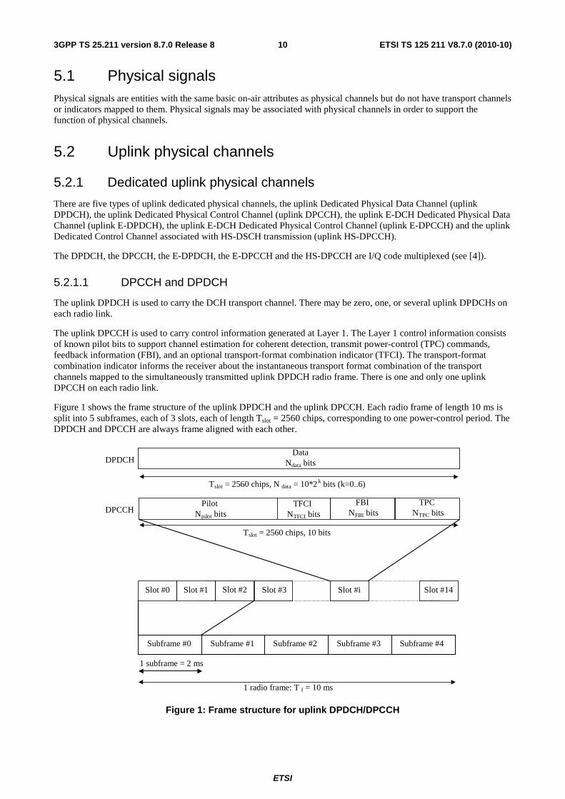
Figure 1 shows the frame structure of the uplink DPDCH and the uplink DPCCH. Each radio frame of length 10 ms is split into 5 subframes, each of 3 slots, each of length Tslot = 2560 chips, corresponding to one power-control period. The DPDCH and DPCCH are always frame aligned with each other.
Pilot N pilot bits
TPC N TPC bits
Data N data bits
Slot #0 Slot #1 Slot #i Slot #14
T slot = 2560 chips, 10 bits
1 radio frame: T f = 10 ms
DPDCH
DPCCH FBI
N FBI bits TFCI
N TFCI bits
T slot = 2560 chips, N data = 10*2 k bits (k=0..6)
Slot #2 Slot #3
Subframe #0 Subframe #1 Subframe #2 Subframe #3 Subframe #4
1 subframe = 2 ms
Figure 1: Frame structure for uplink DPDCH/DPCCH
ETSI
ETSI TS 125 211 V8.7.0 (2010-10)113GPP TS 25.211 version 8.7.0 Release 8
The parameter k in figure 1 determines the number of bits per uplink DPDCH slot. It is related to the spreading factor SF of the DPDCH as SF = 256/2k. The DPDCH spreading factor may range from 256 down to 4. The spreading factor of the uplink DPCCH is always equal to 256, i.e. there are 10 bits per uplink DPCCH slot.
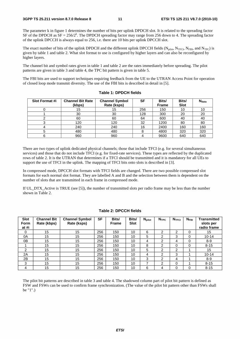
The exact number of bits of the uplink DPDCH and the different uplink DPCCH fields (Npilot, NTFCI, NFBI, and NTPC) is given by table 1 and table 2. What slot format to use is configured by higher layers and can also be reconfigured by higher layers.
The channel bit and symbol rates given in table 1 and table 2 are the rates immediately before spreading. The pilot patterns are given in table 3 and table 4, the TPC bit pattern is given in table 5.
The FBI bits are used to support techniques requiring feedback from the UE to the UTRAN Access Point for operation of closed loop mode transmit diversity. The use of the FBI bits is described in detail in [5].
Table 1: DPDCH fields
Slot Format #i Channel Bit Rate (kbps)
Channel Symbol Rate (ksps)
SF Bits/ Frame
Bits/ Slot
Ndata
0 15 15 256 150 10 10 1 30 30 128 300 20 20 2 60 60 64 600 40 40 3 120 120 32 1200 80 80 4 240 240 16 2400 160 160 5 480 480 8 4800 320 320 6 960 960 4 9600 640 640
There are two types of uplink dedicated physical channels; those that include TFCI (e.g. for several simultaneous services) and those that do not include TFCI (e.g. for fixed-rate services). These types are reflected by the duplicated rows of table 2. It is the UTRAN that determines if a TFCI should be transmitted and it is mandatory for all UEs to support the use of TFCI in the uplink. The mapping of TFCI bits onto slots is described in [3].
In compressed mode, DPCCH slot formats with TFCI fields are changed. There are two possible compressed slot formats for each normal slot format. They are labelled A and B and the selection between them is dependent on the number of slots that are transmitted in each frame in compressed mode.
If UL_DTX_Active is TRUE (see [5]), the number of transmitted slots per radio frame may be less than the number shown in Table 2.
Table 2: DPCCH fields
Slot Format #i
Channel Bit Rate (kbps)
Channel Symbol Rate (ksps)
SF Bits/ Frame
Bits/ Slot
Npilot NTPC NTFCI NFBI Transmitted slots per
radio frame 0 15 15 256 150 10 6 2 2 0 15
0A 15 15 256 150 10 5 2 3 0 10-14 0B 15 15 256 150 10 4 2 4 0 8-9 1 15 15 256 150 10 8 2 0 0 8-15 2 15 15 256 150 10 5 2 2 1 15
2A 15 15 256 150 10 4 2 3 1 10-14 2B 15 15 256 150 10 3 2 4 1 8-9 3 15 15 256 150 10 7 2 0 1 8-15 4 15 15 256 150 10 6 4 0 0 8-15
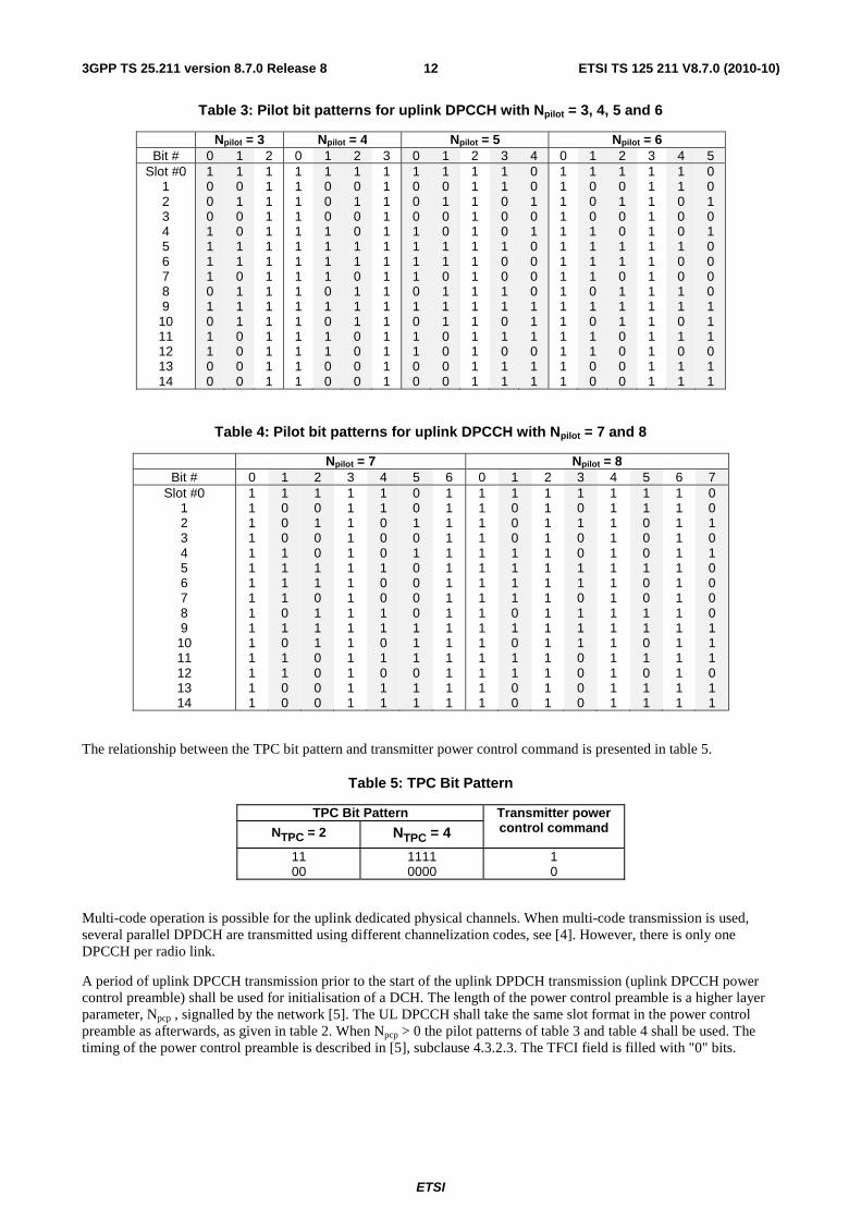
The pilot bit patterns are described in table 3 and table 4. The shadowed column part of pilot bit pattern is defined as FSW and FSWs can be used to confirm frame synchronization. (The value of the pilot bit pattern other than FSWs shall be "1".)
ETSI
ETSI TS 125 211 V8.7.0 (2010-10)123GPP TS 25.211 version 8.7.0 Release 8
Table 3: Pilot bit patterns for uplink DPCCH with Npilot = 3, 4, 5 and 6
Npilot = 3 Npilot = 4 Npilot = 5 Npilot = 6 Bit # 0 1 2 0 1 2 3 0 1 2 3 4 0 1 2 3 4 5
Slot #0 1 2 3 4 5 6 7 8 9
10 11 12 13 14
1 0 0 0 1 1 1 1 0 1 0 1 1 0 0
1 0 1 0 0 1 1 0 1 1 1 0 0 0 0
1 1 1 1 1 1 1 1 1 1 1 1 1 1 1
1 1 1 1 1 1 1 1 1 1 1 1 1 1 1
1 0 0 0 1 1 1 1 0 1 0 1 1 0 0
1 0 1 0 0 1 1 0 1 1 1 0 0 0 0
1 1 1 1 1 1 1 1 1 1 1 1 1 1 1
1 0 0 0 1 1 1 1 0 1 0 1 1 0 0
1 0 1 0 0 1 1 0 1 1 1 0 0 0 0
1 1 1 1 1 1 1 1 1 1 1 1 1 1 1
1 1 0 0 0 1 0 0 1 1 0 1 0 1 1
0 0 1 0 1 0 0 0 0 1 1 1 0 1 1
1 1 1 1 1 1 1 1 1 1 1 1 1 1 1
1 0 0 0 1 1 1 1 0 1 0 1 1 0 0
1 0 1 0 0 1 1 0 1 1 1 0 0 0 0
1 1 1 1 1 1 1 1 1 1 1 1 1 1 1
1 1 0 0 0 1 0 0 1 1 0 1 0 1 1
0 0 1 0 1 0 0 0 0 1 1 1 0 1 1
Table 4: Pilot bit patterns for uplink DPCCH with Npilot = 7 and 8
Npilot = 7 Npilot = 8 Bit # 0 1 2 3 4 5 6 0 1 2 3 4 5 6 7
Slot #0 1 2 3 4 5 6 7 8 9 10 11 12 13 14
1 1 1 1 1 1 1 1 1 1 1 1 1 1 1
1 0 0 0 1 1 1 1 0 1 0 1 1 0 0
1 0 1 0 0 1 1 0 1 1 1 0 0 0 0
1 1 1 1 1 1 1 1 1 1 1 1 1 1 1
1 1 0 0 0 1 0 0 1 1 0 1 0 1 1
0 0 1 0 1 0 0 0 0 1 1 1 0 1 1
1 1 1 1 1 1 1 1 1 1 1 1 1 1 1
1 1 1 1 1 1 1 1 1 1 1 1 1 1 1
1 0 0 0 1 1 1 1 0 1 0 1 1 0 0
1 1 1 1 1 1 1 1 1 1 1 1 1 1 1
1 0 1 0 0 1 1 0 1 1 1 0 0 0 0
1 1 1 1 1 1 1 1 1 1 1 1 1 1 1
1 1 0 0 0 1 0 0 1 1 0 1 0 1 1
1 1 1 1 1 1 1 1 1 1 1 1 1 1 1
0 0 1 0 1 0 0 0 0 1 1 1 0 1 1
The relationship between the TPC bit pattern and transmitter power control command is presented in table 5.
Table 5: TPC Bit Pattern
TPC Bit Pattern Transmitter power control command NTPC = 2 NTPC = 4
11 00
1111 0000
1 0
Multi-code operation is possible for the uplink dedicated physical channels. When multi-code transmission is used, several parallel DPDCH are transmitted using different channelization codes, see [4]. However, there is only one DPCCH per radio link.
A period of uplink DPCCH transmission prior to the start of the uplink DPDCH transmission (uplink DPCCH power control preamble) shall be used for initialisation of a DCH. The length of the power control preamble is a higher layer parameter, Npcp , signalled by the network [5]. The UL DPCCH shall take the same slot format in the power control preamble as afterwards, as given in table 2. When Npcp > 0 the pilot patterns of table 3 and table 4 shall be used. The timing of the power control preamble is described in [5], subclause 4.3.2.3. The TFCI field is filled with "0" bits.

ETSI
ETSI TS 125 211 V8.7.0 (2010-10)133GPP TS 25.211 version 8.7.0 Release 8
5.2.1.2 HS-DPCCH
Figure 2A illustrates the frame structure of the HS-DPCCH. The HS-DPCCH carries uplink feedback signalling related to downlink HS-DSCH transmission and to HS-SCCH orders according to subclause 6A.1.1 in [5]. The feedback signalling consists of Hybrid-ARQ Acknowledgement (HARQ-ACK) and Channel-Quality Indication (CQI) and in case the UE is configured in MIMO mode of Precoding Control Indication (PCI) as well [3]. Each sub frame of length 2 ms (3*2560 chips) consists of 3 slots, each of length 2560 chips. The HARQ-ACK is carried in the first slot of the HS-DPCCH sub-frame. The CQI, and in case the UE is configured in MIMO mode also the PCI, are carried in the second and third slot of a HS-DPCCH sub-frame. There is at most one HS-DPCCH on each radio link. The HS-DPCCH can only exist together with an uplink DPCCH. The timing of the HS-DPCCH relative to the uplink DPCCH is shown in section 7.7.
Subframe #0 Subframe # i Subframe #4
HARQ-ACK CQI/PCI
One radio frame T f = 10 ms
One HS-DPCCH subframe (2 ms)
2 × T slot = 5120 chips T slot = 2560 chips
Figure 2A: Frame structure for uplink HS-DPCCH
The spreading factor of the HS-DPCCH is 256 i.e. there are 10 bits per uplink HS-DPCCH slot. The slot format for uplink HS-DPCCH is defined in Table 5A.
Table 5A: HS-DPCCH fields
Slot Format #i Channel Bit Rate (kbps)
Channel Symbol Rate (ksps)
SF Bits/ Subframe
Bits/ Slot
Transmitted slots per Subframe
0 15 15 256 30 10 3
5.2.1.3 E-DPCCH and E-DPDCH
The E-DPDCH is used to carry the E-DCH transport channel. There may be zero, one, or several E-DPDCH on each radio link.
The E-DPCCH is a physical channel used to transmit control information associated with the E-DCH. There is at most one E-DPCCH on each radio link.
E-DPDCH and E-DPCCH are always transmitted simultaneously, except for the following cases when E-DPCCH is transmitted without E-DPDCH:
- when E-DPDCH but not E-DPCCH is DTXed due to power scaling as described in [5] section 5.1.2.6, or
- during the ndtx E-DPDCH idle slots if nmax>ntx1 as described in [3] section 4.4.5.2.
E-DPCCH shall not be transmitted in a slot unless DPCCH is also transmitted in the same slot.
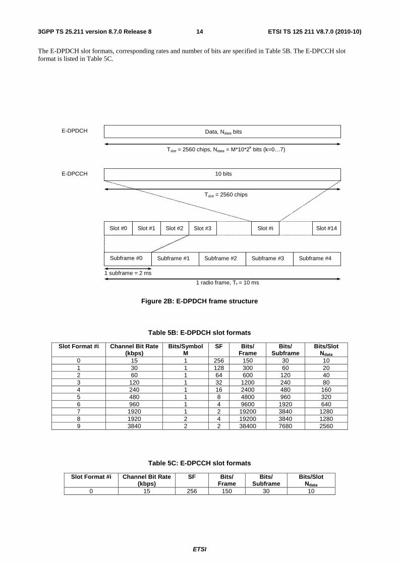
Figure 2B shows the E-DPDCH and E-DPCCH (sub)frame structure. Each radio frame is divided in 5 subframes, each of length 2 ms; the first subframe starts at the start of each radio frame and the 5th subframe ends at the end of each radio frame.
An E-DPDCH may use BPSK or 4PAM modulation symbols. In figure 2B, M is the number of bits per modulation symbol i.e. M=1 for BPSK and M=2 for 4PAM.
ETSI
ETSI TS 125 211 V8.7.0 (2010-10)143GPP TS 25.211 version 8.7.0 Release 8
The E-DPDCH slot formats, corresponding rates and number of bits are specified in Table 5B. The E-DPCCH slot format is listed in Table 5C.
Data, Ndata bits
Slot #1 Slot #14 Slot #2 Slot #i Slot #0
Tslot = 2560 chips, Ndata = M*10*2k bits (k=0…7)
Tslot = 2560 chips
1 subframe = 2 ms
1 radio frame, Tf = 10 ms
E-DPDCH E-DPDCH
E-DPCCH 10 bits
Subframe #0 Subframe #1 Subframe #2 Subframe #3 Subframe #4
Slot #3
Figure 2B: E-DPDCH frame structure
Table 5B: E-DPDCH slot formats
Slot Format #i Channel Bit Rate (kbps)
Bits/Symbol M
SF Bits/ Frame
Bits/ Subframe
Bits/Slot Ndata
0 15 1 256 150 30 10 1 30 1 128 300 60 20 2 60 1 64 600 120 40 3 120 1 32 1200 240 80 4 240 1 16 2400 480 160 5 480 1 8 4800 960 320 6 960 1 4 9600 1920 640 7 1920 1 2 19200 3840 1280 8 1920 2 4 19200 3840 1280 9 3840 2 2 38400 7680 2560
Table 5C: E-DPCCH slot formats
Slot Format #i Channel Bit Rate (kbps)
SF Bits/ Frame
Bits/ Subframe
Bits/Slot Ndata
0 15 256 150 30 10
ETSI
ETSI TS 125 211 V8.7.0 (2010-10)153GPP TS 25.211 version 8.7.0 Release 8
5.2.2 Common uplink physical channels
5.2.2.1 Physical Random Access Channel (PRACH)
The Physical Random Access Channel (PRACH) is used to carry the RACH.
5.2.2.1.1 Overall structure of random-access transmission
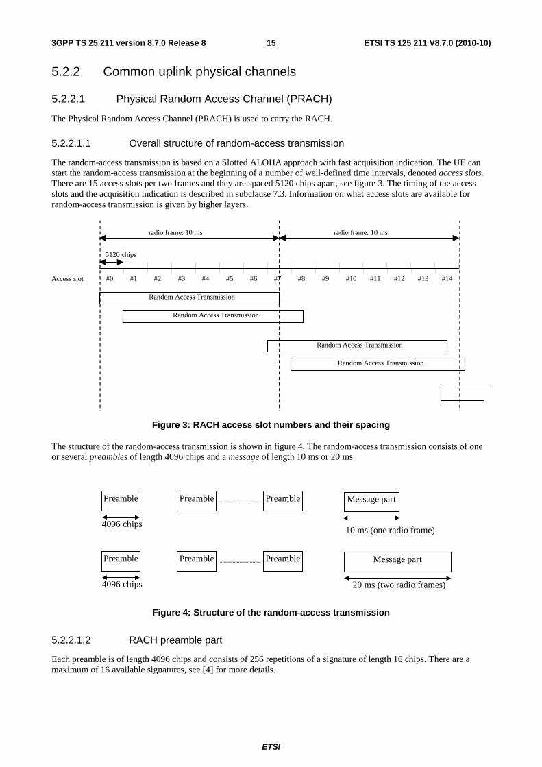
The random-access transmission is based on a Slotted ALOHA approach with fast acquisition indication. The UE can start the random-access transmission at the beginning of a number of well-defined time intervals, denoted access slots. There are 15 access slots per two frames and they are spaced 5120 chips apart, see figure 3. The timing of the access slots and the acquisition indication is described in subclause 7.3. Information on what access slots are available for random-access transmission is given by higher layers.
#0 #1 #2 #3 #4 #5 #6 #7 #8 #9 #10 #11 #12 #13 #14
5120 chips
radio frame: 10 ms radio frame: 10 ms
Access slot
Random Access Transmission
Random Access Transmission
Random Access Transmission
Random Access Transmission
Figure 3: RACH access slot numbers and their spacing
The structure of the random-access transmission is shown in figure 4. The random-access transmission consists of one or several preambles of length 4096 chips and a message of length 10 ms or 20 ms.
Message partPreamble
4096 chips10 ms (one radio frame)
Preamble Preamble
Message partPreamble
4096 chips 20 ms (two radio frames)
Preamble Preamble
Figure 4: Structure of the random-access transmission
5.2.2.1.2 RACH preamble part
Each preamble is of length 4096 chips and consists of 256 repetitions of a signature of length 16 chips. There are a maximum of 16 available signatures, see [4] for more details.
ETSI
ETSI TS 125 211 V8.7.0 (2010-10)163GPP TS 25.211 version 8.7.0 Release 8
5.2.2.1.3 RACH message part
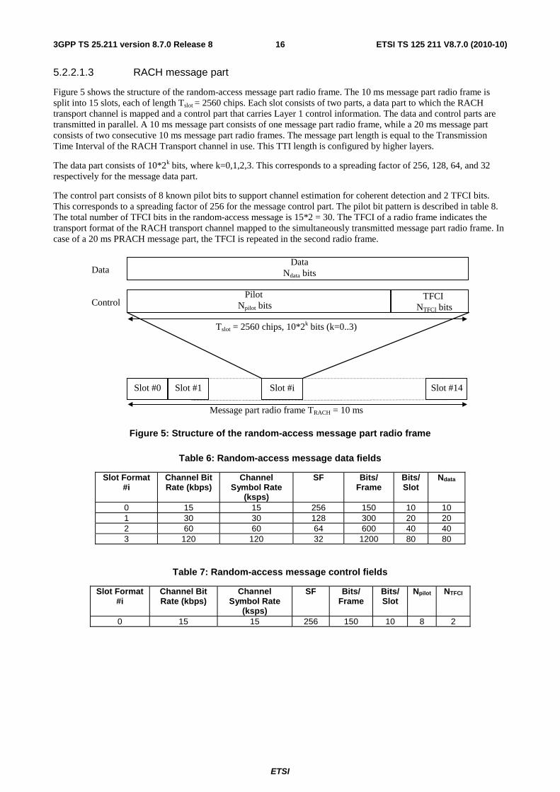
Figure 5 shows the structure of the random-access message part radio frame. The 10 ms message part radio frame is split into 15 slots, each of length Tslot = 2560 chips. Each slot consists of two parts, a data part to which the RACH transport channel is mapped and a control part that carries Layer 1 control information. The data and control parts are transmitted in parallel. A 10 ms message part consists of one message part radio frame, while a 20 ms message part consists of two consecutive 10 ms message part radio frames. The message part length is equal to the Transmission Time Interval of the RACH Transport channel in use. This TTI length is configured by higher layers.
The data part consists of 10*2k bits, where k=0,1,2,3. This corresponds to a spreading factor of 256, 128, 64, and 32 respectively for the message data part.
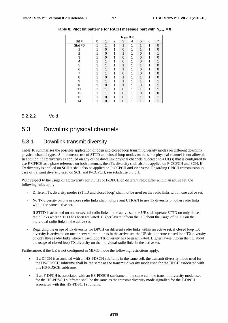
The control part consists of 8 known pilot bits to support channel estimation for coherent detection and 2 TFCI bits. This corresponds to a spreading factor of 256 for the message control part. The pilot bit pattern is described in table 8. The total number of TFCI bits in the random-access message is 15*2 = 30. The TFCI of a radio frame indicates the transport format of the RACH transport channel mapped to the simultaneously transmitted message part radio frame. In case of a 20 ms PRACH message part, the TFCI is repeated in the second radio frame.
Pilot Npilot bits
DataNdata bits
Slot #0 Slot #1 Slot #i Slot #14
Tslot = 2560 chips, 10*2k bits (k=0..3)
Message part radio frame TRACH = 10 ms
Data
ControlTFCI
NTFCI bits
Figure 5: Structure of the random-access message part radio frame
Table 6: Random-access message data fields
Slot Format #i
Channel Bit Rate (kbps)
Channel Symbol Rate
(ksps)
SF Bits/ Frame
Bits/ Slot
Ndata
0 15 15 256 150 10 10 1 30 30 128 300 20 20 2 60 60 64 600 40 40 3 120 120 32 1200 80 80
Table 7: Random-access message control fields
Slot Format #i
Channel Bit Rate (kbps)
Channel Symbol Rate
(ksps)
SF Bits/ Frame
Bits/ Slot
Npilot NTFCI
0 15 15 256 150 10 8 2
ETSI
ETSI TS 125 211 V8.7.0 (2010-10)173GPP TS 25.211 version 8.7.0 Release 8
Table 8: Pilot bit patterns for RACH message part with Npilot = 8
Npilot = 8 Bit # 0 1 2 3 4 5 6 7
Slot #0 1 2 3 4 5 6 7 8 9 10 11 12 13 14
1 1 1 1 1 1 1 1 1 1 1 1 1 1 1
1 0 0 0 1 1 1 1 0 1 0 1 1 0 0
1 1 1 1 1 1 1 1 1 1 1 1 1 1 1
1 0 1 0 0 1 1 0 1 1 1 0 0 0 0
1 1 1 1 1 1 1 1 1 1 1 1 1 1 1
1 1 0 0 0 1 0 0 1 1 0 1 0 1 1
1 1 1 1 1 1 1 1 1 1 1 1 1 1 1
0 0 1 0 1 0 0 0 0 1 1 1 0 1 1
5.2.2.2 Void
5.3 Downlink physical channels
5.3.1 Downlink transmit diversity
Table 10 summarises the possible application of open and closed loop transmit diversity modes on different downlink physical channel types. Simultaneous use of STTD and closed loop modes on the same physical channel is not allowed. In addition, if Tx diversity is applied on any of the downlink physical channels allocated to a UE(s) that is configured to use P-CPICH as a phase reference on both antennas, then Tx diversity shall also be applied on P-CCPCH and SCH. If Tx diversity is applied on SCH it shall also be applied on P-CCPCH and vice versa. Regarding CPICH transmission in case of transmit diversity used on SCH and P-CCPCH, see subclause 5.3.3.1.
With respect to the usage of Tx diversity for DPCH or F-DPCH on different radio links within an active set, the following rules apply:
- Different Tx diversity modes (STTD and closed loop) shall not be used on the radio links within one active set.
- No Tx diversity on one or more radio links shall not prevent UTRAN to use Tx diversity on other radio links within the same active set.
- If STTD is activated on one or several radio links in the active set, the UE shall operate STTD on only those radio links where STTD has been activated. Higher layers inform the UE about the usage of STTD on the individual radio links in the active set.
- Regarding the usage of Tx diversity for DPCH on different radio links within an active set, if closed loop TX diversity is activated on one or several radio links in the active set, the UE shall operate closed loop TX diversity on only those radio links where closed loop TX diversity has been activated. Higher layers inform the UE about the usage of closed loop TX diversity on the individual radio links in the active set.
Furthermore, if the UE is not configured in MIMO mode the following restrictions apply:
• If a DPCH is associated with an HS-PDSCH subframe in the same cell, the transmit diversity mode used for the HS-PDSCH subframe shall be the same as the transmit diversity mode used for the DPCH associated with this HS-PDSCH subframe.
• If an F-DPCH is associated with an HS-PDSCH subframe in the same cell, the transmit diversity mode used for the HS-PDSCH subframe shall be the same as the transmit diversity mode signalled for the F-DPCH associated with this HS-PDSCH subframe.
ETSI
ETSI TS 125 211 V8.7.0 (2010-10)183GPP TS 25.211 version 8.7.0 Release 8
• If neither DPCH nor F-DPCH is associated with an HS-PDSCH subframe the transmit diversity mode used for the HS-PDSCH subframe shall be the STTD if the P-CCPCH in the cell is using transmit diversity. Otherwise, no transmit diversity is used for the HS-PDSCH subframe.
• If the UE is configured with a secondary serving HS-DSCH cell not associated with either DPCH or F-DPCH in the same cell, the diversity mode used for the HS-PDSCH subframe of that cell shall be configured by higher layers and independent from that used in the serving HS-DSCH cell.
If the UE is configured in MIMO mode then a DPCH or F-DPCH associated with an HS-PDSCH subframe can be either in transmit diversity mode or in no transmit diversity mode.
Regardless of whether or not the UE is configured in MIMO mode,
• If the DPCH associated with an HS-SCCH subframe in the same cell is using either open or closed loop transmit diversity on the radio link transmitted from the HS-DSCH serving cell, the HS-SCCH subframe from this cell shall be transmitted using STTD, otherwise no transmit diversity shall be used for this HS-SCCH subframe.
• If an F-DPCH for which STTD is signalled is associated with an HS-SCCH subframe in the same cell, the HS-SCCH subframe shall be transmitted using STTD, otherwise no transmit diversity shall be used for this HS-SCCH subframe.
• If neither DPCH nor F-DPCH is associated with an HS-SCCH subframe the transmit diversity mode used for the HS-SCCH subframe shall be the STTD if the P-CCPCH in the cell is using transmit diversity. Otherwise, no transmit diversity is used for the HS-SCCH subframe.
• If the UE is configured with a secondary serving HS-DSCH cell not associated with either DPCH or F-DPCH in the same cell, the diversity mode used for the HS-SCCH subframe of that cell shall be configured by higher layers and independent from that used in the serving HS-DSCH cell.
The transmit diversity mode on the associated DPCH or F-DPCH may not change during a HS-SCCH and or HS-PDSCH subframe and within the slot prior to the HS-SCCH subframe. This includes any change between no Tx diversity and either open loop or closed loop mode.
If the UE is receiving a DPCH on which transmit diversity is used from a cell, or if the UE is receiving an F-DPCH for which STTD is signalled from a cell, the UE shall assume that the E-AGCH, E-RGCH, and E-HICH from the same cell are transmitted using STTD.
ETSI
ETSI TS 125 211 V8.7.0 (2010-10)193GPP TS 25.211 version 8.7.0 Release 8
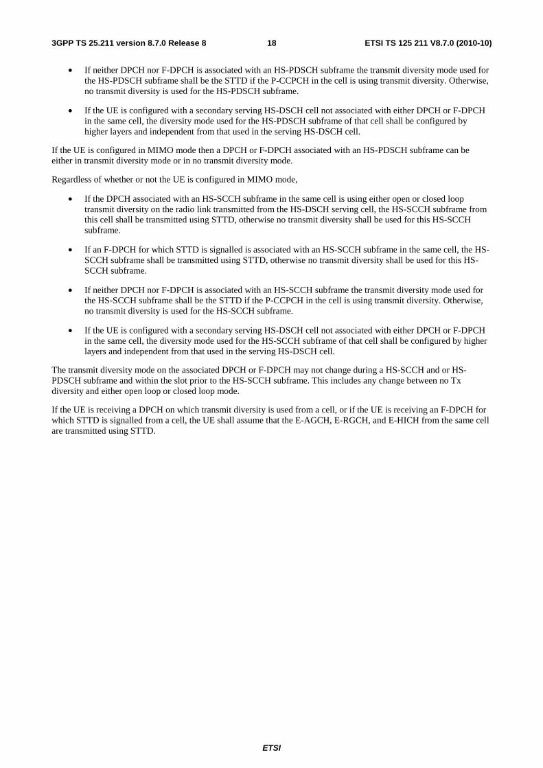
Table 10: Application of Tx diversity modes on downlink physical channel types "X" – can be applied, "–" – not applied
Physical channel type Open loop mode Closed loop mode
TSTD STTD Mode 1 P-CCPCH – X – SCH X – – S-CCPCH – X – DPCH – X X F-DPCH – X – PICH – X – MICH – X – HS-PDSCH (UE not in MIMO mode, UE configured without a secondary serving HS-DSCH cell)
– X X
HS-PDSCH (UE not in MIMO mode, UE configured with a secondary serving HS-DSCH cell) (*1)
– X –
HS-PDSCH (UE in MIMO mode) – – – HS-SCCH (*1) – X – E-AGCH – X – E-RGCH – X – E-HICH – X – AICH – X –
NOTE *1: The Tx diversity mode can be configured independently across cells.
5.3.1.1 Open loop transmit diversity
5.3.1.1.1 Space time block coding based transmit antenna diversity (STTD)
The open loop downlink transmit diversity employs a space time block coding based transmit diversity (STTD).
The STTD encoding is optional in UTRAN. STTD support is mandatory at the UE.
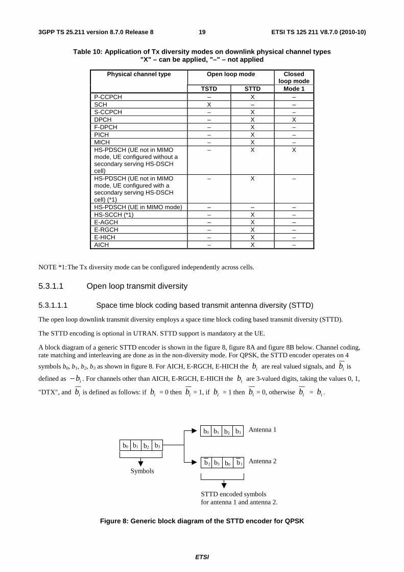
A block diagram of a generic STTD encoder is shown in the figure 8, figure 8A and figure 8B below. Channel coding, rate matching and interleaving are done as in the non-diversity mode. For QPSK, the STTD encoder operates on 4
symbols b0, b1, b2, b3 as shown in figure 8. For AICH, E-RGCH, E-HICH the ib are real valued signals, and ib is
defined as ib− . For channels other than AICH, E-RGCH, E-HICH the ib are 3-valued digits, taking the values 0, 1,
"DTX", and ib is defined as follows: if ib = 0 then ib = 1, if ib = 1 then ib = 0, otherwise ib = ib .
b0 b1 b2 b3
b0 b1 b2 b3
b2 b3 b0 b1
Antenna 1
Antenna 2
Symbols
STTD encoded symbolsfor antenna 1 and antenna 2.
Figure 8: Generic block diagram of the STTD encoder for QPSK
ETSI
ETSI TS 125 211 V8.7.0 (2010-10)203GPP TS 25.211 version 8.7.0 Release 8
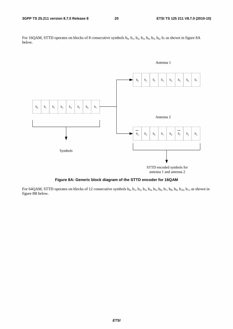
For 16QAM, STTD operates on blocks of 8 consecutive symbols b0, b1, b2, b3, b4, b5, b6, b7 as shown in figure 8A below.
b0 b1 b2 b4b3 b5 b7b6
b0 b1 b2 b4b3 b5 b7b6
b4 b5 b6 b0b7 b1 b3b2
Antenna 1
Antenna 2
Symbols
STTD encoded symbols forantenna 1 and antenna 2
Figure 8A: Generic block diagram of the STTD encoder for 16QAM
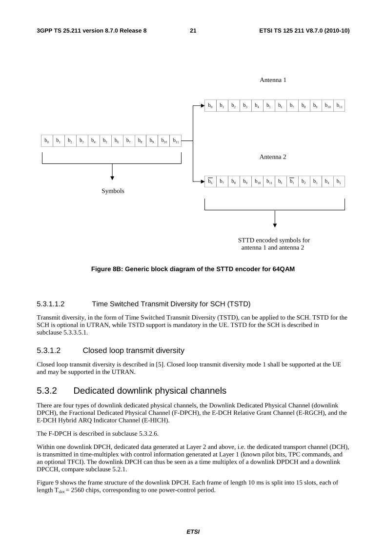
For 64QAM, STTD operates on blocks of 12 consecutive symbols b0, b1, b2, b3, b4, b5, b6, b7, b8, b9, b10, b11 as shown in figure 8B below.
ETSI
ETSI TS 125 211 V8.7.0 (2010-10)213GPP TS 25.211 version 8.7.0 Release 8
Figure 8B: Generic block diagram of the STTD encoder for 64QAM
5.3.1.1.2 Time Switched Transmit Diversity for SCH (TSTD)
Transmit diversity, in the form of Time Switched Transmit Diversity (TSTD), can be applied to the SCH. TSTD for the SCH is optional in UTRAN, while TSTD support is mandatory in the UE. TSTD for the SCH is described in subclause 5.3.3.5.1.
5.3.1.2 Closed loop transmit diversity
Closed loop transmit diversity is described in [5]. Closed loop transmit diversity mode 1 shall be supported at the UE and may be supported in the UTRAN.
5.3.2 Dedicated downlink physical channels
There are four types of downlink dedicated physical channels, the Downlink Dedicated Physical Channel (downlink DPCH), the Fractional Dedicated Physical Channel (F-DPCH), the E-DCH Relative Grant Channel (E-RGCH), and the E-DCH Hybrid ARQ Indicator Channel (E-HICH).
The F-DPCH is described in subclause 5.3.2.6.
Within one downlink DPCH, dedicated data generated at Layer 2 and above, i.e. the dedicated transport channel (DCH), is transmitted in time-multiplex with control information generated at Layer 1 (known pilot bits, TPC commands, and an optional TFCI). The downlink DPCH can thus be seen as a time multiplex of a downlink DPDCH and a downlink DPCCH, compare subclause 5.2.1.
Figure 9 shows the frame structure of the downlink DPCH. Each frame of length 10 ms is split into 15 slots, each of length Tslot = 2560 chips, corresponding to one power-control period.
Antenna 1
Antenna 2
Symbols
STTD encoded symbols forantenna 1 and antenna 2
b0 b1 b2 b3 b4 b5 b6 b7 b8 b9 b10 b11
b0 b1 b2 b3 b4 b5 b6 b7 b8 b9 b10 b11
b6 b7 b8 b9 b4 b5b0 b1 b2 b3b10 b11

ETSI
ETSI TS 125 211 V8.7.0 (2010-10)223GPP TS 25.211 version 8.7.0 Release 8
One radio frame, Tf = 10 ms
TPC NTPC bits
Slot #0 Slot #1 Slot #i Slot #14
Tslot = 2560 chips, 10*2k bits (k=0..7)
Data2Ndata2 bits
DPDCH
TFCI NTFCI bits
Pilot Npilot bits
Data1Ndata1 bits
DPDCH DPCCH DPCCH
Figure 9: Frame structure for downlink DPCH
The parameter k in figure 9 determines the total number of bits per downlink DPCH slot. It is related to the spreading factor SF of the physical channel as SF = 512/2k. The spreading factor may thus range from 512 down to 4.
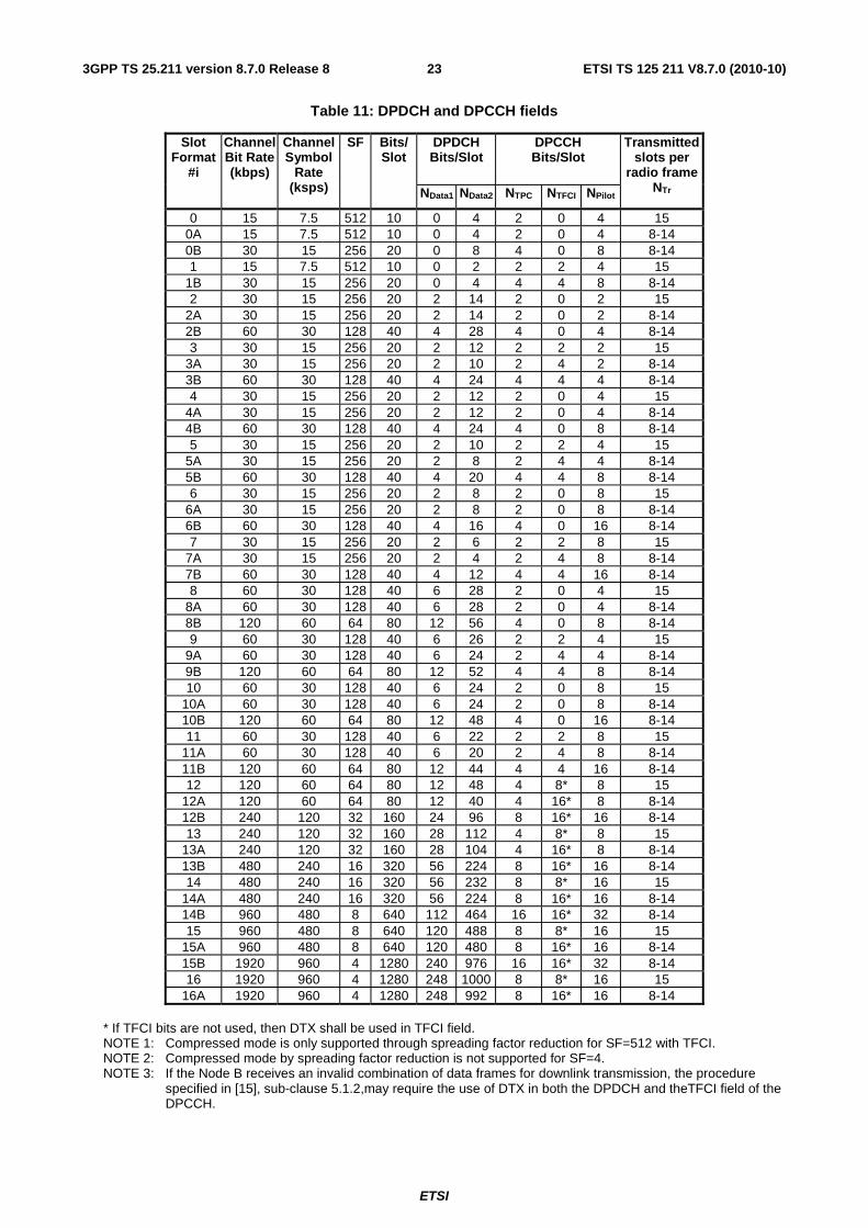
The exact number of bits of the different downlink DPCH fields (Npilot, NTPC, NTFCI, Ndata1 and Ndata2) is given in table 11. What slot format to use is configured by higher layers and can also be reconfigured by higher layers.
There are basically two types of downlink Dedicated Physical Channels; those that include TFCI (e.g. for several simultaneous services) and those that do not include TFCI (e.g. for fixed-rate services). These types are reflected by the duplicated rows of table 11. It is the UTRAN that determines if a TFCI should be transmitted and it is mandatory for all UEs to support the use of TFCI in the downlink. The mapping of TFCI bits onto slots is described in [3].
In compressed frames, a different slot format is used compared to normal mode. There are two possible compressed slot formats that are labelled A and B. Slot format B shall be used in frames compressed by spreading factor reduction and slot format A shall be used in frames compressed by higher layer scheduling. The channel bit and symbol rates given in table 11 are the rates immediately before spreading.
ETSI
ETSI TS 125 211 V8.7.0 (2010-10)233GPP TS 25.211 version 8.7.0 Release 8
Table 11: DPDCH and DPCCH fields
Slot Format
#i
Channel Bit Rate (kbps)
Channel Symbol
Rate (ksps)
SF Bits/ Slot
DPDCH Bits/Slot
DPCCH Bits/Slot
Transmitted slots per
radio frame NTr NData1 NData2 NTPC NTFCI NPilot
0 15 7.5 512 10 0 4 2 0 4 15 0A 15 7.5 512 10 0 4 2 0 4 8-14 0B 30 15 256 20 0 8 4 0 8 8-14 1 15 7.5 512 10 0 2 2 2 4 15
1B 30 15 256 20 0 4 4 4 8 8-14 2 30 15 256 20 2 14 2 0 2 15
2A 30 15 256 20 2 14 2 0 2 8-14 2B 60 30 128 40 4 28 4 0 4 8-14 3 30 15 256 20 2 12 2 2 2 15
3A 30 15 256 20 2 10 2 4 2 8-14 3B 60 30 128 40 4 24 4 4 4 8-14 4 30 15 256 20 2 12 2 0 4 15
4A 30 15 256 20 2 12 2 0 4 8-14 4B 60 30 128 40 4 24 4 0 8 8-14 5 30 15 256 20 2 10 2 2 4 15
5A 30 15 256 20 2 8 2 4 4 8-14 5B 60 30 128 40 4 20 4 4 8 8-14 6 30 15 256 20 2 8 2 0 8 15
6A 30 15 256 20 2 8 2 0 8 8-14 6B 60 30 128 40 4 16 4 0 16 8-14 7 30 15 256 20 2 6 2 2 8 15
7A 30 15 256 20 2 4 2 4 8 8-14 7B 60 30 128 40 4 12 4 4 16 8-14 8 60 30 128 40 6 28 2 0 4 15
8A 60 30 128 40 6 28 2 0 4 8-14 8B 120 60 64 80 12 56 4 0 8 8-14 9 60 30 128 40 6 26 2 2 4 15
9A 60 30 128 40 6 24 2 4 4 8-14 9B 120 60 64 80 12 52 4 4 8 8-14 10 60 30 128 40 6 24 2 0 8 15
10A 60 30 128 40 6 24 2 0 8 8-14 10B 120 60 64 80 12 48 4 0 16 8-14 11 60 30 128 40 6 22 2 2 8 15
11A 60 30 128 40 6 20 2 4 8 8-14 11B 120 60 64 80 12 44 4 4 16 8-14 12 120 60 64 80 12 48 4 8* 8 15
12A 120 60 64 80 12 40 4 16* 8 8-14 12B 240 120 32 160 24 96 8 16* 16 8-14 13 240 120 32 160 28 112 4 8* 8 15
13A 240 120 32 160 28 104 4 16* 8 8-14 13B 480 240 16 320 56 224 8 16* 16 8-14 14 480 240 16 320 56 232 8 8* 16 15
14A 480 240 16 320 56 224 8 16* 16 8-14 14B 960 480 8 640 112 464 16 16* 32 8-14 15 960 480 8 640 120 488 8 8* 16 15
15A 960 480 8 640 120 480 8 16* 16 8-14 15B 1920 960 4 1280 240 976 16 16* 32 8-14 16 1920 960 4 1280 248 1000 8 8* 16 15
16A 1920 960 4 1280 248 992 8 16* 16 8-14 * If TFCI bits are not used, then DTX shall be used in TFCI field. NOTE 1: Compressed mode is only supported through spreading factor reduction for SF=512 with TFCI. NOTE 2: Compressed mode by spreading factor reduction is not supported for SF=4. NOTE 3: If the Node B receives an invalid combination of data frames for downlink transmission, the procedure
specified in [15], sub-clause 5.1.2,may require the use of DTX in both the DPDCH and theTFCI field of the DPCCH.
ETSI
ETSI TS 125 211 V8.7.0 (2010-10)243GPP TS 25.211 version 8.7.0 Release 8
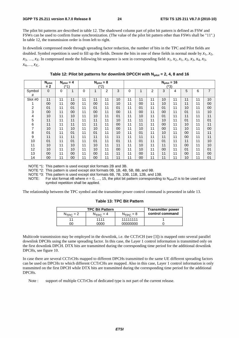
The pilot bit patterns are described in table 12. The shadowed column part of pilot bit pattern is defined as FSW and FSWs can be used to confirm frame synchronization. (The value of the pilot bit pattern other than FSWs shall be "11".) In table 12, the transmission order is from left to right.
In downlink compressed mode through spreading factor reduction, the number of bits in the TPC and Pilot fields are doubled. Symbol repetition is used to fill up the fields. Denote the bits in one of these fields in normal mode by x1, x2, x3, …, xX. In compressed mode the following bit sequence is sent in corresponding field: x1, x2, x1, x2, x3, x4, x3, x4,…, xX,.
Table 12: Pilot bit patterns for downlink DPCCH with Npilot = 2, 4, 8 and 16
Npilot = 2
Npilot = 4 (*1)
Npilot = 8 (*2)
Npilot = 16 (*3)
Symbol #
0 0 1 0 1 2 3 0 1 2 3 4 5 6 7
Slot #0 1 2 3 4 5 6 7 8 9 10 11 12 13 14
11 00 01 00 10 11 11 10 01 11 01 10 10 00 00
11 11 11 11 11 11 11 11 11 11 11 11 11 11 11
11 00 01 00 10 11 11 10 01 11 01 10 10 00 00
11 11 11 11 11 11 11 11 11 11 11 11 11 11 11
11 00 01 00 10 11 11 10 01 11 01 10 10 00 00
11 11 11 11 11 11 11 11 11 11 11 11 11 11 11
10 10 01 00 01 10 00 00 10 11 01 11 00 11 11
11 11 11 11 11 11 11 11 11 11 11 11 11 11 11
11 00 01 00 10 11 11 10 01 11 01 10 10 00 00
11 11 11 11 11 11 11 11 11 11 11 11 11 11 11
10 10 01 00 01 10 00 00 10 11 01 11 00 11 11
11 11 11 11 11 11 11 11 11 11 11 11 11 11 11
11 11 10 01 11 01 10 10 00 00 11 00 01 00 10
11 11 11 11 11 11 11 11 11 11 11 11 11 11 11
10 00 00 10 11 01 11 00 11 11 10 10 01 00 01
NOTE *1: This pattern is used except slot formats 2B and 3B. NOTE *2: This pattern is used except slot formats 0B, 1B, 4B, 5B, 8B, and 9B. NOTE *3: This pattern is used except slot formats 6B, 7B, 10B, 11B, 12B, and 13B. NOTE: For slot format nB where n = 0, …, 15, the pilot bit pattern corresponding to Npilot/2 is to be used and
symbol repetition shall be applied. The relationship between the TPC symbol and the transmitter power control command is presented in table 13.
Table 13: TPC Bit Pattern
TPC Bit Pattern Transmitter power control command NTPC = 2 NTPC = 4 NTPC = 8
11 00
1111 0000
11111111 00000000
1 0
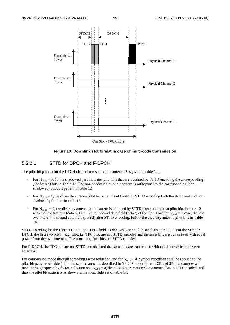
Multicode transmission may be employed in the downlink, i.e. the CCTrCH (see [3]) is mapped onto several parallel downlink DPCHs using the same spreading factor. In this case, the Layer 1 control information is transmitted only on the first downlink DPCH. DTX bits are transmitted during the corresponding time period for the additional downlink DPCHs, see figure 10.
In case there are several CCTrCHs mapped to different DPCHs transmitted to the same UE different spreading factors can be used on DPCHs to which different CCTrCHs are mapped. Also in this case, Layer 1 control information is only transmitted on the first DPCH while DTX bits are transmitted during the corresponding time period for the additional DPCHs.
Note : support of multiple CCTrChs of dedicated type is not part of the current release.
ETSI
ETSI TS 125 211 V8.7.0 (2010-10)253GPP TS 25.211 version 8.7.0 Release 8
TransmissionPower Physical Channel 1
TransmissionPower Physical Channel 2
TransmissionPower Physical Channel L
DPDCH
One Slot (2560 chips)
TFCI PilotTPC
• •
•
DPDCH
Figure 10: Downlink slot format in case of multi-code transmission
5.3.2.1 STTD for DPCH and F-DPCH
The pilot bit pattern for the DPCH channel transmitted on antenna 2 is given in table 14.
- For Npilot = 8, 16 the shadowed part indicates pilot bits that are obtained by STTD encoding the corresponding (shadowed) bits in Table 12. The non-shadowed pilot bit pattern is orthogonal to the corresponding (non-shadowed) pilot bit pattern in table 12.
- For Npilot = 4, the diversity antenna pilot bit pattern is obtained by STTD encoding both the shadowed and non-shadowed pilot bits in table 12.
- For Npilot = 2, the diversity antenna pilot pattern is obtained by STTD encoding the two pilot bits in table 12 with the last two bits (data or DTX) of the second data field (data2) of the slot. Thus for Npilot = 2 case, the last two bits of the second data field (data 2) after STTD encoding, follow the diversity antenna pilot bits in Table 14.
STTD encoding for the DPDCH, TPC, and TFCI fields is done as described in subclause 5.3.1.1.1. For the SF=512 DPCH, the first two bits in each slot, i.e. TPC bits, are not STTD encoded and the same bits are transmitted with equal power from the two antennas. The remaining four bits are STTD encoded.
For F-DPCH, the TPC bits are not STTD encoded and the same bits are transmitted with equal power from the two antennas.
For compressed mode through spreading factor reduction and for Npilot > 4, symbol repetition shall be applied to the pilot bit patterns of table 14, in the same manner as described in 5.3.2. For slot formats 2B and 3B, i.e. compressed mode through spreading factor reduction and Npilot = 4, the pilot bits transmitted on antenna 2 are STTD encoded, and thus the pilot bit pattern is as shown in the most right set of table 14.
ETSI
ETSI TS 125 211 V8.7.0 (2010-10)263GPP TS 25.211 version 8.7.0 Release 8
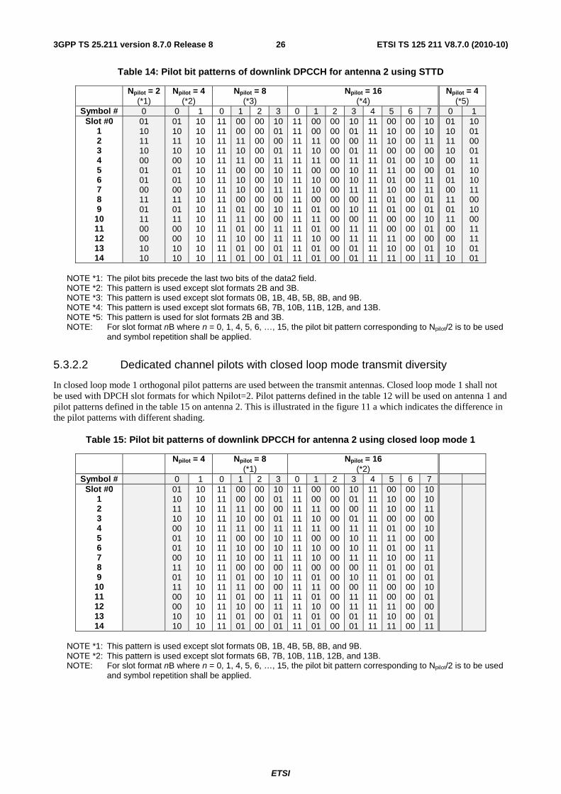
Table 14: Pilot bit patterns of downlink DPCCH for antenna 2 using STTD
Npilot = 2 (*1)
Npilot = 4 (*2)
Npilot = 8 (*3)
Npilot = 16 (*4)
Npilot = 4 (*5)
Symbol # 0 0 1 0 1 2 3 0 1 2 3 4 5 6 7 0 1 Slot #0
1 2 3 4 5 6 7 8 9
10 11 12 13 14
01 10 11 10 00 01 01 00 11 01 11 00 00 10 10
01 10 11 10 00 01 01 00 11 01 11 00 00 10 10
10 10 10 10 10 10 10 10 10 10 10 10 10 10 10
11 11 11 11 11 11 11 11 11 11 11 11 11 11 11
00 00 11 10 11 00 10 10 00 01 11 01 10 01 01
00 00 00 00 00 00 00 00 00 00 00 00 00 00 00
10 01 00 01 11 10 10 11 00 10 00 11 11 01 01
11 11 11 11 11 11 11 11 11 11 11 11 11 11 11
00 00 11 10 11 00 10 10 00 01 11 01 10 01 01
00 00 00 00 00 00 00 00 00 00 00 00 00 00 00
10 01 00 01 11 10 10 11 00 10 00 11 11 01 01
11 11 11 11 11 11 11 11 11 11 11 11 11 11 11
00 10 10 00 01 11 01 10 01 01 00 00 11 10 11
00 00 00 00 00 00 00 00 00 00 00 00 00 00 00
10 10 11 00 10 00 11 11 01 01 10 01 00 01 11
01 10 11 10 00 01 01 00 11 01 11 00 00 10 10
10 01 00 01 11 10 10 11 00 10 00 11 11 01 01
NOTE *1: The pilot bits precede the last two bits of the data2 field. NOTE *2: This pattern is used except slot formats 2B and 3B. NOTE *3: This pattern is used except slot formats 0B, 1B, 4B, 5B, 8B, and 9B. NOTE *4: This pattern is used except slot formats 6B, 7B, 10B, 11B, 12B, and 13B. NOTE *5: This pattern is used for slot formats 2B and 3B. NOTE: For slot format nB where n = 0, 1, 4, 5, 6, …, 15, the pilot bit pattern corresponding to Npilot/2 is to be used
and symbol repetition shall be applied.
5.3.2.2 Dedicated channel pilots with closed loop mode transmit diversity
In closed loop mode 1 orthogonal pilot patterns are used between the transmit antennas. Closed loop mode 1 shall not be used with DPCH slot formats for which Npilot=2. Pilot patterns defined in the table 12 will be used on antenna 1 and pilot patterns defined in the table 15 on antenna 2. This is illustrated in the figure 11 a which indicates the difference in the pilot patterns with different shading.
Table 15: Pilot bit patterns of downlink DPCCH for antenna 2 using closed loop mode 1
Npilot = 4 Npilot = 8 (*1)
Npilot = 16 (*2)
Symbol # 0 1 0 1 2 3 0 1 2 3 4 5 6 7 Slot #0
1 2 3 4 5 6 7 8 9
10 11 12 13 14
01 10 11 10 00 01 01 00 11 01 11 00 00 10 10
10 10 10 10 10 10 10 10 10 10 10 10 10 10 10
11 11 11 11 11 11 11 11 11 11 11 11 11 11 11
00 00 11 10 11 00 10 10 00 01 11 01 10 01 01
00 00 00 00 00 00 00 00 00 00 00 00 00 00 00
10 01 00 01 11 10 10 11 00 10 00 11 11 01 01
11 11 11 11 11 11 11 11 11 11 11 11 11 11 11
00 00 11 10 11 00 10 10 00 01 11 01 10 01 01
00 00 00 00 00 00 00 00 00 00 00 00 00 00 00
10 01 00 01 11 10 10 11 00 10 00 11 11 01 01
11 11 11 11 11 11 11 11 11 11 11 11 11 11 11
00 10 10 00 01 11 01 10 01 01 00 00 11 10 11
00 00 00 00 00 00 00 00 00 00 00 00 00 00 00
10 10 11 00 10 00 11 11 01 01 10 01 00 01 11
NOTE *1: This pattern is used except slot formats 0B, 1B, 4B, 5B, 8B, and 9B. NOTE *2: This pattern is used except slot formats 6B, 7B, 10B, 11B, 12B, and 13B. NOTE: For slot format nB where n = 0, 1, 4, 5, 6, …, 15, the pilot bit pattern corresponding to Npilot/2 is to be used
and symbol repetition shall be applied.
ETSI
ETSI TS 125 211 V8.7.0 (2010-10)273GPP TS 25.211 version 8.7.0 Release 8
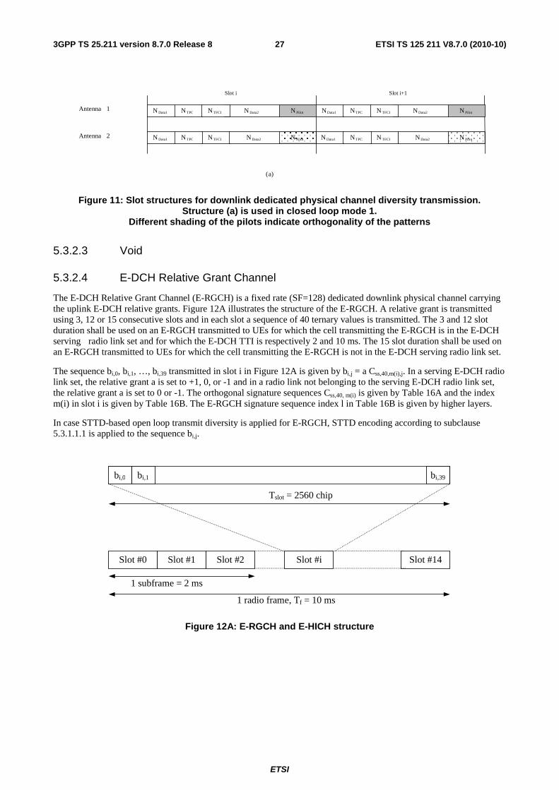
Figure 11: Slot structures for downlink dedicated physical channel diversity transmission. Structure (a) is used in closed loop mode 1.
Different shading of the pilots indicate orthogonality of the patterns
5.3.2.3 Void
5.3.2.4 E-DCH Relative Grant Channel
The E-DCH Relative Grant Channel (E-RGCH) is a fixed rate (SF=128) dedicated downlink physical channel carrying the uplink E-DCH relative grants. Figure 12A illustrates the structure of the E-RGCH. A relative grant is transmitted using 3, 12 or 15 consecutive slots and in each slot a sequence of 40 ternary values is transmitted. The 3 and 12 slot duration shall be used on an E-RGCH transmitted to UEs for which the cell transmitting the E-RGCH is in the E-DCH serving radio link set and for which the E-DCH TTI is respectively 2 and 10 ms. The 15 slot duration shall be used on an E-RGCH transmitted to UEs for which the cell transmitting the E-RGCH is not in the E-DCH serving radio link set.
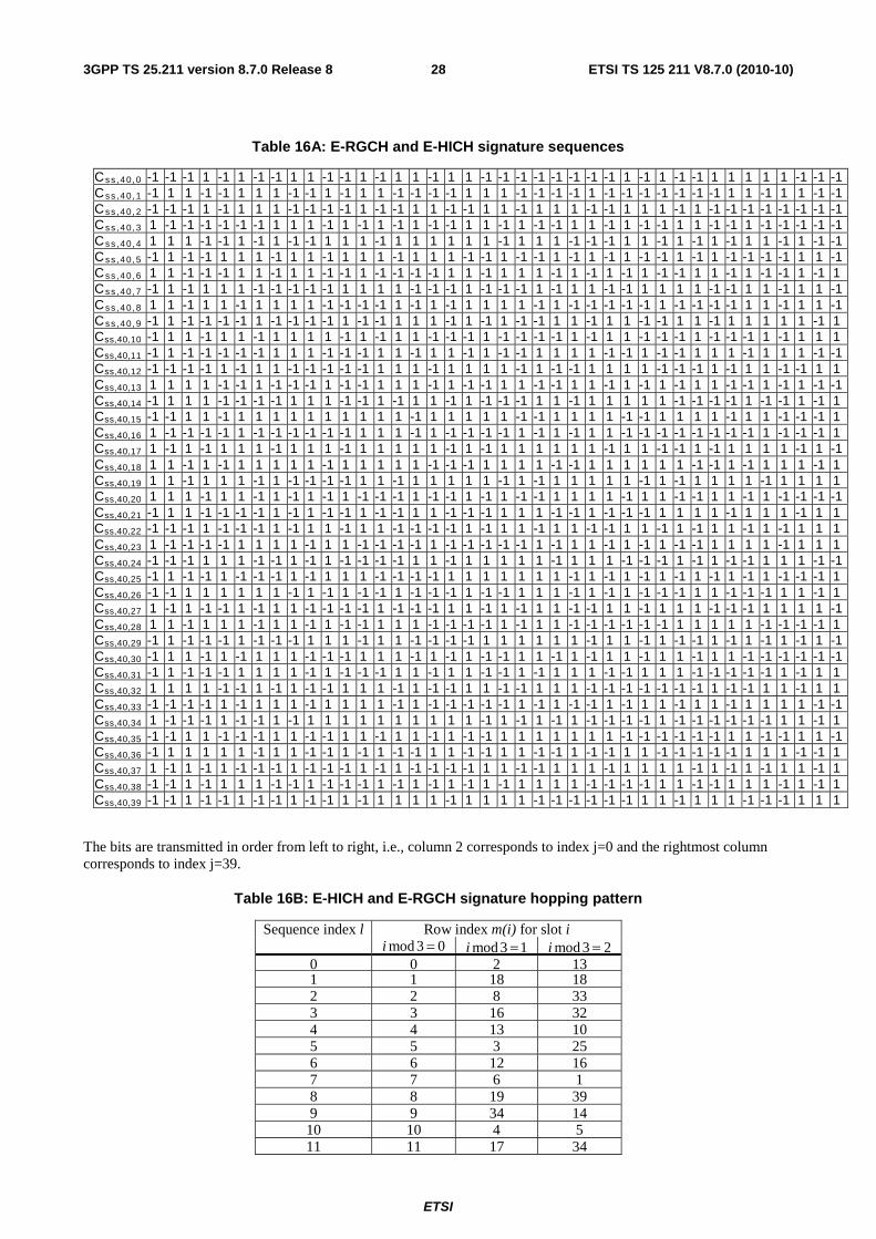
The sequence bi,0, bi,1, …, bi,39 transmitted in slot i in Figure 12A is given by bi,j = a Css,40,m(i),j. In a serving E-DCH radio link set, the relative grant a is set to +1, 0, or -1 and in a radio link not belonging to the serving E-DCH radio link set, the relative grant a is set to 0 or -1. The orthogonal signature sequences Css,40, m(i) is given by Table 16A and the index m(i) in slot i is given by Table 16B. The E-RGCH signature sequence index l in Table 16B is given by higher layers.
In case STTD-based open loop transmit diversity is applied for E-RGCH, STTD encoding according to subclause 5.3.1.1.1 is applied to the sequence bi,j.
Slot #14
Tslot = 2560 chip
bi,39 bi,1 bi,0
Slot #0 Slot #1 Slot #2 Slot #i
1 radio frame, Tf = 10 ms
1 subframe = 2 ms
Figure 12A: E-RGCH and E-HICH structure
N Pilot
N Pilot
Antenna 1
Antenna 2
Slot i Slot i+1
N Data2N Data1
N TFCIN Data1
( a)
N TPC
N TPC N Data2
N TFCI N PilotN Data2N Data1 N TPC N TFCI
N PilotN TFCIN Data1 N TPC N Data2
ETSI
ETSI TS 125 211 V8.7.0 (2010-10)283GPP TS 25.211 version 8.7.0 Release 8
Table 16A: E-RGCH and E-HICH signature sequences
Cs s ,4 0 , 0 -1 -1 -1 1 -1 1 -1 -1 1 1 -1 -1 1 -1 1 1 -1 1 1 -1 -1 -1 -1 -1 -1 -1 -1 1 -1 1 -1 -1 1 1 1 1 1 -1 -1 -1 Cs s ,4 0 , 1 -1 1 1 -1 -1 1 1 1 -1 -1 1 -1 1 1 -1 -1 -1 -1 1 1 1 -1 -1 -1 -1 1 -1 -1 -1 -1 -1 -1 -1 1 1 -1 1 1 -1 -1 Cs s ,4 0 , 2 -1 -1 -1 1 -1 1 1 1 -1 -1 -1 -1 1 -1 -1 1 1 -1 -1 1 1 -1 1 1 1 -1 -1 1 1 1 -1 1 -1 -1 -1 -1 -1 -1 -1 -1 Cs s ,4 0 , 3 1 -1 -1 -1 -1 -1 -1 1 1 1 -1 1 -1 1 -1 1 -1 -1 1 1 -1 1 -1 -1 1 1 -1 1 -1 -1 1 1 -1 -1 1 -1 -1 -1 -1 -1 Cs s ,4 0 , 4 1 1 1 -1 -1 1 -1 1 -1 -1 1 1 1 -1 1 1 1 1 1 1 -1 1 1 1 -1 -1 -1 1 1 -1 1 -1 1 -1 1 1 -1 1 -1 -1 Cs s ,4 0 , 5 -1 1 -1 -1 1 1 1 -1 1 1 -1 1 1 1 -1 1 1 1 -1 -1 1 -1 -1 1 -1 1 -1 1 -1 -1 1 -1 1 -1 -1 -1 -1 1 1 -1 Cs s ,4 0 , 6 1 1 -1 -1 -1 1 1 -1 1 1 -1 -1 1 -1 -1 -1 -1 1 1 -1 1 1 1 -1 1 -1 1 -1 1 -1 -1 1 1 -1 1 -1 -1 1 -1 1 Cs s ,4 0 , 7 -1 1 -1 1 1 1 -1 -1 -1 -1 -1 1 1 1 1 -1 -1 -1 1 -1 -1 -1 1 -1 1 1 -1 -1 1 1 1 1 -1 -1 1 1 -1 1 1 -1 Cs s ,4 0 , 8 1 1 -1 1 1 -1 1 1 1 1 -1 -1 -1 -1 1 -1 1 -1 1 1 1 1 -1 1 -1 -1 -1 -1 -1 1 -1 -1 -1 -1 1 1 -1 1 1 -1 Cs s ,4 0 , 9 -1 1 -1 -1 -1 -1 1 -1 -1 -1 -1 1 -1 -1 1 1 1 -1 1 -1 1 -1 -1 1 1 -1 1 1 -1 -1 1 1 -1 1 1 1 1 1 -1 1 Css,40,10 -1 1 1 -1 1 1 -1 1 1 1 1 -1 1 -1 1 1 -1 -1 -1 1 -1 -1 -1 -1 1 -1 1 1 -1 -1 -1 1 -1 -1 -1 1 -1 1 1 1 Css,40,11 -1 1 -1 -1 -1 -1 -1 1 1 1 -1 -1 -1 1 1 -1 1 1 -1 1 -1 -1 1 1 1 1 -1 -1 1 -1 -1 1 1 1 -1 1 1 1 -1 -1 Css,40,12 -1 -1 -1 -1 1 -1 1 1 -1 -1 -1 -1 -1 1 1 1 -1 1 1 1 1 -1 1 -1 -1 1 1 1 1 -1 -1 -1 1 -1 1 1 -1 -1 1 1 Css,40,13 1 1 1 1 -1 -1 1 -1 -1 -1 1 -1 -1 1 1 1 -1 1 -1 -1 1 1 -1 -1 1 1 -1 1 -1 1 -1 1 1 -1 -1 1 -1 1 -1 -1 Css,40,14 -1 1 1 1 -1 -1 -1 -1 1 1 1 -1 -1 1 -1 1 1 -1 1 -1 -1 -1 1 1 -1 1 1 1 1 1 -1 -1 -1 -1 1 -1 -1 1 -1 1 Css,40,15 -1 -1 1 1 -1 1 1 1 1 1 1 1 1 1 1 -1 1 1 1 1 1 -1 -1 1 1 1 1 -1 -1 1 1 1 1 -1 1 1 -1 -1 -1 1 Css,40,16 1 -1 -1 -1 -1 1 -1 -1 -1 -1 -1 -1 1 1 1 -1 1 -1 -1 -1 -1 1 -1 1 -1 1 1 -1 -1 -1 -1 -1 -1 -1 -1 1 -1 -1 -1 1 Css,40,17 1 -1 1 -1 1 1 1 -1 1 1 1 -1 1 1 1 1 1 -1 1 -1 1 1 1 1 1 1 -1 1 1 -1 -1 1 -1 1 1 1 1 -1 1 -1 Css,40,18 1 1 -1 1 -1 1 1 1 1 1 -1 1 1 1 1 1 -1 -1 -1 1 1 1 1 -1 -1 1 1 1 1 1 1 -1 -1 1 -1 1 1 1 -1 1 Css,40,19 1 1 -1 1 1 1 -1 1 -1 -1 -1 -1 1 1 -1 1 1 1 1 1 -1 1 -1 1 1 1 1 1 -1 1 -1 1 1 1 1 -1 1 1 1 1 Css,40,20 1 1 1 -1 1 1 -1 1 -1 1 -1 1 -1 -1 -1 1 -1 -1 1 -1 1 -1 -1 1 1 1 1 -1 1 1 -1 -1 1 1 -1 1 -1 -1 -1 -1 Css,40,21 -1 1 1 -1 -1 -1 -1 1 -1 1 -1 -1 1 -1 -1 1 1 -1 -1 -1 1 1 1 -1 -1 1 -1 -1 -1 1 1 1 1 -1 1 1 1 -1 1 1 Css,40,22 -1 -1 -1 1 -1 -1 -1 1 -1 1 1 -1 1 1 -1 -1 -1 -1 1 -1 1 1 -1 1 1 -1 -1 1 1 -1 1 -1 1 1 -1 1 -1 1 1 1 Css,40,23 1 -1 -1 -1 -1 1 1 1 1 -1 1 1 -1 -1 -1 -1 1 -1 -1 -1 -1 -1 1 -1 1 1 -1 1 -1 1 -1 -1 1 1 1 1 -1 1 1 1 Css,40,24 -1 -1 -1 1 1 1 -1 -1 1 -1 1 -1 -1 -1 -1 1 1 -1 1 1 1 1 1 -1 1 1 1 -1 -1 -1 1 -1 1 -1 -1 1 1 1 -1 -1 Css,40,25 -1 1 -1 -1 1 -1 -1 -1 1 -1 1 1 1 -1 -1 -1 -1 1 1 1 1 1 1 1 -1 1 -1 1 -1 1 -1 1 -1 1 -1 1 -1 -1 -1 1 Css,40,26 -1 -1 1 1 1 1 1 1 -1 1 -1 1 -1 -1 1 -1 -1 -1 1 -1 -1 1 1 1 -1 1 -1 1 -1 -1 -1 1 1 -1 -1 -1 1 1 -1 1 Css,40,27 1 -1 1 -1 -1 1 -1 1 1 -1 -1 -1 -1 1 -1 -1 -1 1 1 -1 1 -1 1 1 -1 -1 1 1 -1 1 1 1 -1 -1 -1 1 1 1 1 -1 Css,40,28 1 1 -1 1 1 1 -1 1 1 -1 1 -1 -1 1 1 1 -1 -1 -1 -1 1 -1 1 1 -1 -1 -1 -1 -1 -1 1 1 1 1 1 -1 -1 -1 -1 1 Css,40,29 -1 1 -1 -1 -1 1 -1 -1 -1 1 1 1 -1 1 1 -1 -1 -1 -1 1 1 1 1 1 1 -1 1 1 -1 1 -1 -1 1 -1 1 -1 1 -1 1 -1 Css,40,30 -1 1 1 -1 1 -1 1 1 1 -1 -1 -1 1 1 1 -1 1 -1 1 -1 -1 1 1 -1 1 -1 1 1 -1 1 1 -1 1 1 -1 -1 -1 -1 -1 -1 Css,40,31 -1 1 -1 -1 -1 1 1 1 1 -1 1 -1 -1 -1 1 1 -1 1 1 -1 -1 1 -1 1 1 1 -1 -1 1 1 1 -1 -1 -1 -1 -1 1 -1 1 1 Css,40,32 1 1 1 1 -1 -1 1 -1 1 -1 -1 1 1 1 -1 1 -1 -1 1 1 -1 -1 1 1 1 -1 -1 -1 -1 -1 -1 -1 1 -1 -1 1 1 -1 1 1 Css,40,33 -1 -1 -1 -1 1 -1 1 1 1 -1 1 1 1 1 -1 1 -1 -1 -1 -1 -1 1 -1 1 -1 -1 1 -1 1 1 -1 1 1 -1 1 1 1 1 -1 -1 Css,40,34 1 -1 -1 -1 1 -1 -1 1 -1 1 1 1 1 1 1 1 1 1 1 -1 1 -1 1 -1 1 -1 -1 -1 -1 1 -1 -1 -1 -1 -1 -1 1 1 -1 1 Css,40,35 -1 -1 1 1 -1 -1 -1 1 1 -1 -1 1 1 -1 1 1 -1 1 -1 -1 1 1 1 1 1 1 1 -1 -1 -1 -1 -1 -1 1 1 -1 -1 1 1 -1 Css,40,36 -1 1 1 1 1 1 -1 1 1 -1 -1 1 -1 1 -1 -1 1 1 -1 -1 1 1 -1 -1 1 -1 -1 1 1 -1 -1 -1 -1 -1 1 1 1 -1 -1 1 Css,40,37 1 -1 1 -1 1 -1 -1 -1 1 -1 -1 -1 1 -1 1 -1 -1 -1 -1 1 1 -1 -1 1 1 1 -1 1 1 1 1 -1 1 -1 1 -1 1 1 -1 1 Css,40,38 -1 -1 1 -1 1 1 1 -1 -1 1 -1 -1 -1 1 -1 1 -1 1 -1 1 -1 1 1 1 1 -1 -1 -1 -1 1 1 -1 -1 1 1 1 -1 1 -1 1 Css,40,39 -1 -1 1 -1 -1 1 -1 -1 1 -1 -1 1 -1 1 1 1 1 -1 1 1 1 1 -1 -1 -1 -1 -1 -1 1 1 -1 1 1 1 -1 -1 -1 1 1 1
The bits are transmitted in order from left to right, i.e., column 2 corresponds to index j=0 and the rightmost column corresponds to index j=39.
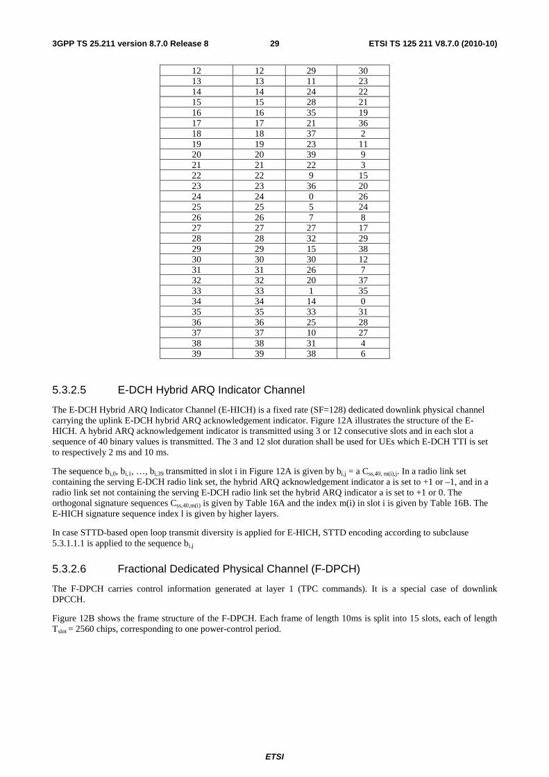
Table 16B: E-HICH and E-RGCH signature hopping pattern
Sequence index l Row index m(i) for slot i 03mod =i 13mod =i 23mod =i
0 0 2 13 1 1 18 18 2 2 8 33 3 3 16 32 4 4 13 10 5 5 3 25 6 6 12 16 7 7 6 1 8 8 19 39 9 9 34 14
10 10 4 5 11 11 17 34
ETSI
ETSI TS 125 211 V8.7.0 (2010-10)293GPP TS 25.211 version 8.7.0 Release 8
12 12 29 30 13 13 11 23 14 14 24 22 15 15 28 21 16 16 35 19 17 17 21 36 18 18 37 2 19 19 23 11 20 20 39 9 21 21 22 3 22 22 9 15 23 23 36 20 24 24 0 26 25 25 5 24 26 26 7 8 27 27 27 17 28 28 32 29 29 29 15 38 30 30 30 12 31 31 26 7 32 32 20 37 33 33 1 35 34 34 14 0 35 35 33 31 36 36 25 28 37 37 10 27 38 38 31 4 39 39 38 6
5.3.2.5 E-DCH Hybrid ARQ Indicator Channel
The E-DCH Hybrid ARQ Indicator Channel (E-HICH) is a fixed rate (SF=128) dedicated downlink physical channel carrying the uplink E-DCH hybrid ARQ acknowledgement indicator. Figure 12A illustrates the structure of the E-HICH. A hybrid ARQ acknowledgement indicator is transmitted using 3 or 12 consecutive slots and in each slot a sequence of 40 binary values is transmitted. The 3 and 12 slot duration shall be used for UEs which E-DCH TTI is set to respectively 2 ms and 10 ms.
The sequence bi,0, bi,1, …, bi,39 transmitted in slot i in Figure 12A is given by bi,j = a Css,40, m(i),j. In a radio link set containing the serving E-DCH radio link set, the hybrid ARQ acknowledgement indicator a is set to +1 or –1, and in a radio link set not containing the serving E-DCH radio link set the hybrid ARQ indicator a is set to +1 or 0. The orthogonal signature sequences Css,40,m(i) is given by Table 16A and the index m(i) in slot i is given by Table 16B. The E-HICH signature sequence index l is given by higher layers.
In case STTD-based open loop transmit diversity is applied for E-HICH, STTD encoding according to subclause 5.3.1.1.1 is applied to the sequence bi,j
5.3.2.6 Fractional Dedicated Physical Channel (F-DPCH)
The F-DPCH carries control information generated at layer 1 (TPC commands). It is a special case of downlink DPCCH.
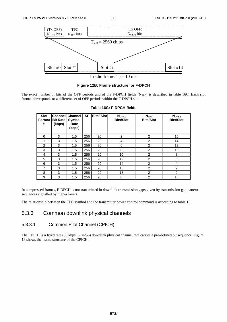
Figure 12B shows the frame structure of the F-DPCH. Each frame of length 10ms is split into 15 slots, each of length Tslot = 2560 chips, corresponding to one power-control period.
ETSI
ETSI TS 125 211 V8.7.0 (2010-10)303GPP TS 25.211 version 8.7.0 Release 8
(Tx OFF) NOFF2 bits
Slot #0 Slot #1 Slot #i Slot #14
Tslot = 2560 chips
1 radio frame: Tf = 10 ms
TPC NTPC bits
(Tx OFF) NOFF1 bits
Figure 12B: Frame structure for F-DPCH
The exact number of bits of the OFF periods and of the F-DPCH fields (NTPC) is described in table 16C. Each slot format corresponds to a different set of OFF periods within the F-DPCH slot.
Table 16C: F-DPCH fields
Slot Format
#i
Channel Bit Rate (kbps)
Channel Symbol
Rate (ksps)
SF Bits/ Slot NOFF1 Bits/Slot
NTPC Bits/Slot
NOFF2 Bits/Slot
0 3 1.5 256 20 2 2 16 1 3 1.5 256 20 4 2 14 2 3 1.5 256 20 6 2 12 3 3 1.5 256 20 8 2 10 4 3 1.5 256 20 10 2 8 5 3 1.5 256 20 12 2 6 6 3 1.5 256 20 14 2 4 7 3 1.5 256 20 16 2 2 8 3 1.5 256 20 18 2 0 9 3 1.5 256 20 0 2 18
In compressed frames, F-DPCH is not transmitted in downlink transmission gaps given by transmission gap pattern sequences signalled by higher layers.
The relationship between the TPC symbol and the transmitter power control command is according to table 13.
5.3.3 Common downlink physical channels
5.3.3.1 Common Pilot Channel (CPICH)
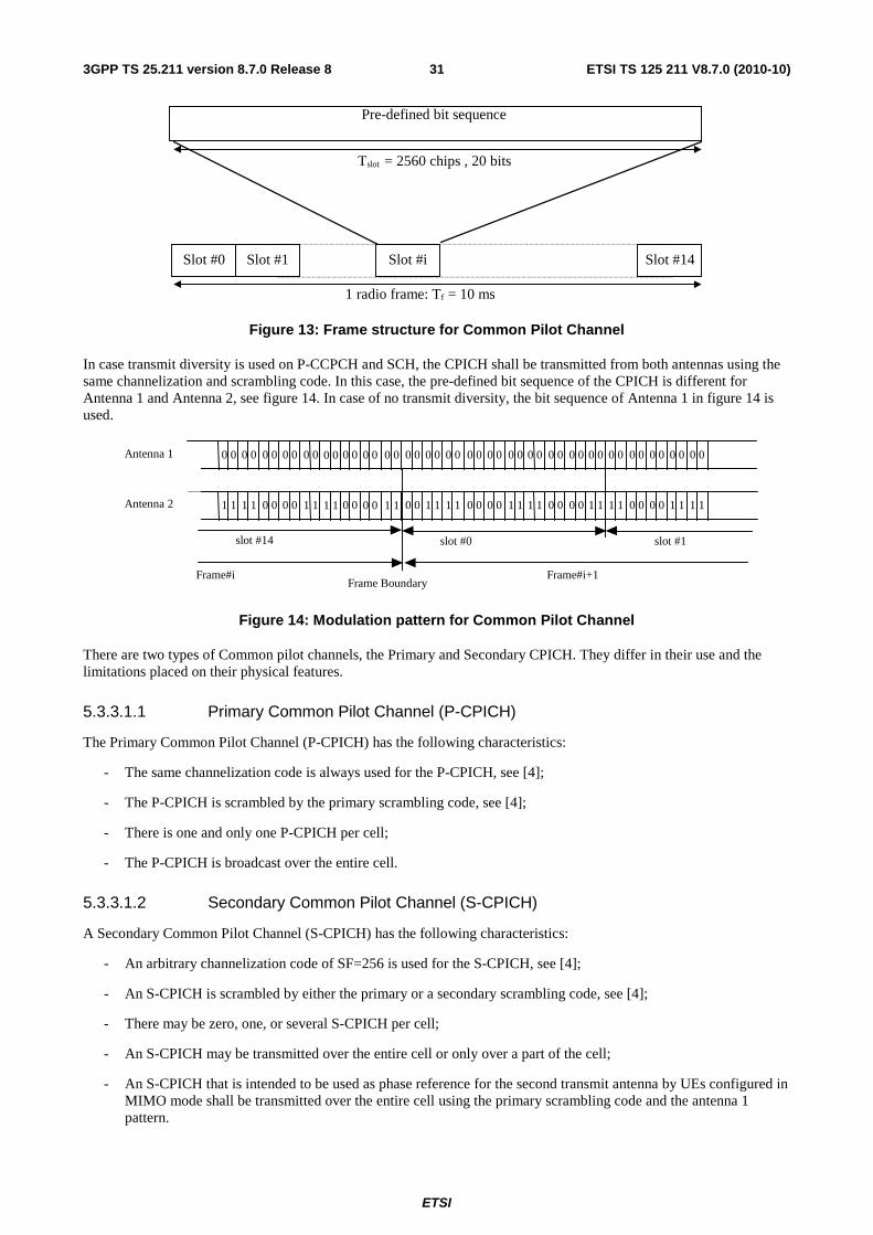
The CPICH is a fixed rate (30 kbps, SF=256) downlink physical channel that carries a pre-defined bit sequence. Figure 13 shows the frame structure of the CPICH.
ETSI
ETSI TS 125 211 V8.7.0 (2010-10)313GPP TS 25.211 version 8.7.0 Release 8
Pre-defined bit sequence
Slot #0 Slot #1 Slot #i Slot #14
Tslot = 2560 chips , 20 bits
1 radio frame: Tf = 10 ms
Figure 13: Frame structure for Common Pilot Channel
In case transmit diversity is used on P-CCPCH and SCH, the CPICH shall be transmitted from both antennas using the same channelization and scrambling code. In this case, the pre-defined bit sequence of the CPICH is different for Antenna 1 and Antenna 2, see figure 14. In case of no transmit diversity, the bit sequence of Antenna 1 in figure 14 is used.
slot #1
Frame#i+1Frame#i
slot #14
Antenna 2
Antenna 1
slot #0
Frame Boundary
0 0 0 0 0 0 0 0 0 0 0 0 0 0 0 0 0 0 0 0 0 0 0 0 0 0 0 0 0 0 0 0 0 0 0 0 0 0 0 0 0 0 0 0 0 0 0 0
1 1 1 1 0 0 0 0 1 1 1 1 0 0 0 0 1 1 0 0 1 1 1 1 0 0 0 0 1 1 1 1 0 0 0 0 1 1 1 1 0 0 0 0 1 1 1 1
Figure 14: Modulation pattern for Common Pilot Channel
There are two types of Common pilot channels, the Primary and Secondary CPICH. They differ in their use and the limitations placed on their physical features.
5.3.3.1.1 Primary Common Pilot Channel (P-CPICH)
The Primary Common Pilot Channel (P-CPICH) has the following characteristics:
- The same channelization code is always used for the P-CPICH, see [4];
- The P-CPICH is scrambled by the primary scrambling code, see [4];
- There is one and only one P-CPICH per cell;
- The P-CPICH is broadcast over the entire cell.
5.3.3.1.2 Secondary Common Pilot Channel (S-CPICH)
A Secondary Common Pilot Channel (S-CPICH) has the following characteristics:
- An arbitrary channelization code of SF=256 is used for the S-CPICH, see [4];
- An S-CPICH is scrambled by either the primary or a secondary scrambling code, see [4];
- There may be zero, one, or several S-CPICH per cell;
- An S-CPICH may be transmitted over the entire cell or only over a part of the cell;
- An S-CPICH that is intended to be used as phase reference for the second transmit antenna by UEs configured in MIMO mode shall be transmitted over the entire cell using the primary scrambling code and the antenna 1 pattern.
ETSI
ETSI TS 125 211 V8.7.0 (2010-10)323GPP TS 25.211 version 8.7.0 Release 8
5.3.3.2 Downlink phase reference
Table 17 specifies the channels which the UE may use as a phase reference for each downlink physical channel type; it also specifies whether the channels which the UE may use as a phase reference for a channel of a particular type shall be assumed to be the same as the ones which the UE may use as a phase reference for the associated DPCH or F-DPCH, if configured.
For the DPCH or F-DPCH and the associated downlink physical channels the following always applies:
• The UE may use the DPCH pilot bits as a phase reference.
• In addition, the UE may use either the primary CPICH or a secondary CPICH as a phase reference.
o By default (i.e. without any indication by higher layers) the UE may use the primary CPICH as a phase reference.
o When a UE is not configured in MIMO mode: The UE is informed by higher layers when it may use a secondary CPICH as a phase reference. In this case the UE shall not use the primary CPICH as a phase reference. Indication that a secondary CPICH may be a phase reference is also applicable when open loop or closed loop TX diversity is enabled for a downlink physical channel in which case Antenna 1 and Antenna 2 secondary CPICH shall be used as phase references.
o When the UE is configured in MIMO mode: The UE is informed by higher layers when it may use a secondary CPICH as a phase reference for a second transmit antenna in addition to the primary CPICH which will be transmitted from the first antenna. In addition, if the UE supports open loop Tx diversity on associated physical channels with the combination of primary CPICH and secondary CPICH , this combination of phase references can also be used as phase references for associated physical channels configured with open loop Tx diversity. If the UE does not support open loop Tx diversity on associated physical channels with the combination of primary CPICH and secondary CPICH and if secondary CPICH is used as a phase reference for second transmit antenna, UE may assume that associated physical channels are not in Tx diversity mode.If no secondary CPICH is signalled as phase reference, the UE may use the Antenna 1 and Antenna 2 primary CPICH as phase references.
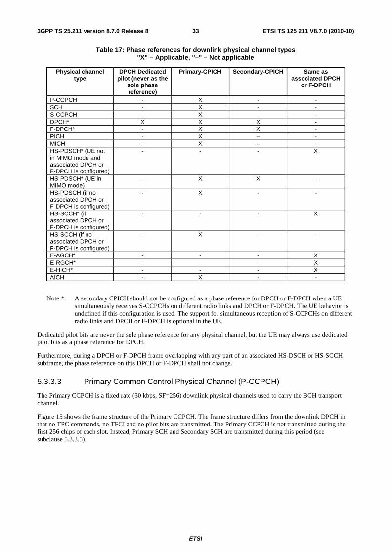
ETSI
ETSI TS 125 211 V8.7.0 (2010-10)333GPP TS 25.211 version 8.7.0 Release 8
Table 17: Phase references for downlink physical channel types "X" – Applicable, "–" – Not applicable
Physical channel type
DPCH Dedicated pilot (never as the
sole phase reference)
Primary-CPICH Secondary-CPICH Same as associated DPCH
or F-DPCH
P-CCPCH - X - - SCH - X - - S-CCPCH - X - - DPCH* X X X - F-DPCH* - X X - PICH - X – - MICH - X – - HS-PDSCH* (UE not in MIMO mode and associated DPCH or F-DPCH is configured)
- - - X
HS-PDSCH* (UE in MIMO mode)
- X X -
HS-PDSCH (if no associated DPCH or F-DPCH is configured)
- X - -
HS-SCCH* (if associated DPCH or F-DPCH is configured)
- - - X
HS-SCCH (if no associated DPCH or F-DPCH is configured)
- X - -
E-AGCH* - - - X E-RGCH* - - - X E-HICH* - - - X AICH - X - -
Note *: A secondary CPICH should not be configured as a phase reference for DPCH or F-DPCH when a UE simultaneously receives S-CCPCHs on different radio links and DPCH or F-DPCH. The UE behavior is undefined if this configuration is used. The support for simultaneous reception of S-CCPCHs on different radio links and DPCH or F-DPCH is optional in the UE.
Dedicated pilot bits are never the sole phase reference for any physical channel, but the UE may always use dedicated pilot bits as a phase reference for DPCH.
Furthermore, during a DPCH or F-DPCH frame overlapping with any part of an associated HS-DSCH or HS-SCCH subframe, the phase reference on this DPCH or F-DPCH shall not change.
5.3.3.3 Primary Common Control Physical Channel (P-CCPCH)
The Primary CCPCH is a fixed rate (30 kbps, SF=256) downlink physical channels used to carry the BCH transport channel.
Figure 15 shows the frame structure of the Primary CCPCH. The frame structure differs from the downlink DPCH in that no TPC commands, no TFCI and no pilot bits are transmitted. The Primary CCPCH is not transmitted during the first 256 chips of each slot. Instead, Primary SCH and Secondary SCH are transmitted during this period (see subclause 5.3.3.5).
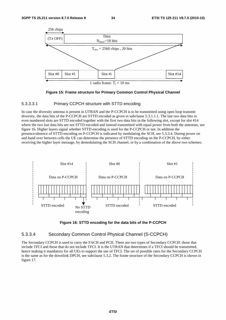
ETSI
ETSI TS 125 211 V8.7.0 (2010-10)343GPP TS 25.211 version 8.7.0 Release 8
Data Ndata1=18 bits
Slot #0 Slot #1 Slot #i Slot #14
Tslot = 2560 chips , 20 bits
1 radio frame: Tf = 10 ms
(Tx OFF)
256 chips
Figure 15: Frame structure for Primary Common Control Physical Channel
5.3.3.3.1 Primary CCPCH structure with STTD encoding
In case the diversity antenna is present in UTRAN and the P-CCPCH is to be transmitted using open loop transmit diversity, the data bits of the P-CCPCH are STTD encoded as given in subclause 5.3.1.1.1. The last two data bits in even numbered slots are STTD encoded together with the first two data bits in the following slot, except for slot #14 where the two last data bits are not STTD encoded and instead transmitted with equal power from both the antennas, see figure 16. Higher layers signal whether STTD encoding is used for the P-CCPCH or not. In addition the presence/absence of STTD encoding on P-CCPCH is indicated by modulating the SCH, see 5.3.3.4. During power on and hand over between cells the UE can determine the presence of STTD encoding on the P-CCPCH, by either receiving the higher layer message, by demodulating the SCH channel, or by a combination of the above two schemes.
STTD encoded STTD encoded
Data on P-CCPCH
Slot #0 Slot #1
Data on P-CCPCH
Slot #14
Data on P-CCPCH
No STTDencoding
STTD encoded
Figure 16: STTD encoding for the data bits of the P-CCPCH
5.3.3.4 Secondary Common Control Physical Channel (S-CCPCH)
The Secondary CCPCH is used to carry the FACH and PCH. There are two types of Secondary CCPCH: those that include TFCI and those that do not include TFCI. It is the UTRAN that determines if a TFCI should be transmitted, hence making it mandatory for all UEs to support the use of TFCI. The set of possible rates for the Secondary CCPCH is the same as for the downlink DPCH, see subclause 5.3.2. The frame structure of the Secondary CCPCH is shown in figure 17.
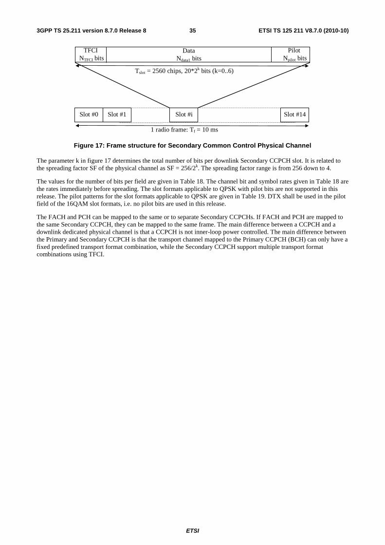
ETSI
ETSI TS 125 211 V8.7.0 (2010-10)353GPP TS 25.211 version 8.7.0 Release 8
Slot #0 Slot #1 Slot #i Slot #14
Tslot = 2560 chips, 20*2k bits (k=0..6)
Pilot Npilot bits
Data Ndata1 bits
1 radio frame: Tf = 10 ms
TFCI NTFCI bits
Figure 17: Frame structure for Secondary Common Control Physical Channel
The parameter k in figure 17 determines the total number of bits per downlink Secondary CCPCH slot. It is related to the spreading factor SF of the physical channel as SF = 256/2k. The spreading factor range is from 256 down to 4.
The values for the number of bits per field are given in Table 18. The channel bit and symbol rates given in Table 18 are the rates immediately before spreading. The slot formats applicable to QPSK with pilot bits are not supported in this release. The pilot patterns for the slot formats applicable to QPSK are given in Table 19. DTX shall be used in the pilot field of the 16QAM slot formats, i.e. no pilot bits are used in this release.
The FACH and PCH can be mapped to the same or to separate Secondary CCPCHs. If FACH and PCH are mapped to the same Secondary CCPCH, they can be mapped to the same frame. The main difference between a CCPCH and a downlink dedicated physical channel is that a CCPCH is not inner-loop power controlled. The main difference between the Primary and Secondary CCPCH is that the transport channel mapped to the Primary CCPCH (BCH) can only have a fixed predefined transport format combination, while the Secondary CCPCH support multiple transport format combinations using TFCI.
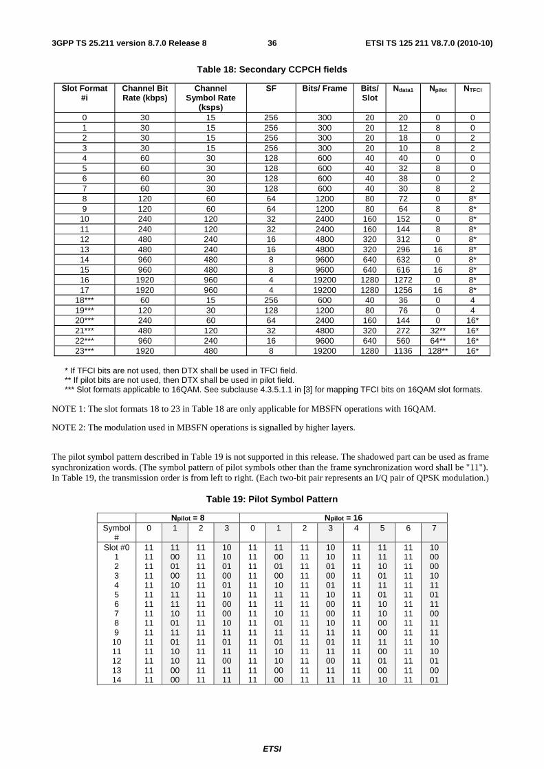
ETSI
ETSI TS 125 211 V8.7.0 (2010-10)363GPP TS 25.211 version 8.7.0 Release 8
Table 18: Secondary CCPCH fields
Slot Format #i
Channel Bit Rate (kbps)
Channel Symbol Rate
(ksps)
SF Bits/ Frame Bits/ Slot
Ndata1 Npilot NTFCI
0 30 15 256 300 20 20 0 0 1 30 15 256 300 20 12 8 0 2 30 15 256 300 20 18 0 2 3 30 15 256 300 20 10 8 2 4 60 30 128 600 40 40 0 0 5 60 30 128 600 40 32 8 0 6 60 30 128 600 40 38 0 2 7 60 30 128 600 40 30 8 2 8 120 60 64 1200 80 72 0 8* 9 120 60 64 1200 80 64 8 8*
10 240 120 32 2400 160 152 0 8* 11 240 120 32 2400 160 144 8 8* 12 480 240 16 4800 320 312 0 8* 13 480 240 16 4800 320 296 16 8* 14 960 480 8 9600 640 632 0 8* 15 960 480 8 9600 640 616 16 8* 16 1920 960 4 19200 1280 1272 0 8* 17 1920 960 4 19200 1280 1256 16 8*
18*** 60 15 256 600 40 36 0 4 19*** 120 30 128 1200 80 76 0 4 20*** 240 60 64 2400 160 144 0 16* 21*** 480 120 32 4800 320 272 32** 16* 22*** 960 240 16 9600 640 560 64** 16* 23*** 1920 480 8 19200 1280 1136 128** 16*
* If TFCI bits are not used, then DTX shall be used in TFCI field. ** If pilot bits are not used, then DTX shall be used in pilot field. *** Slot formats applicable to 16QAM. See subclause 4.3.5.1.1 in [3] for mapping TFCI bits on 16QAM slot formats.
NOTE 1: The slot formats 18 to 23 in Table 18 are only applicable for MBSFN operations with 16QAM.
NOTE 2: The modulation used in MBSFN operations is signalled by higher layers.
The pilot symbol pattern described in Table 19 is not supported in this release. The shadowed part can be used as frame synchronization words. (The symbol pattern of pilot symbols other than the frame synchronization word shall be "11"). In Table 19, the transmission order is from left to right. (Each two-bit pair represents an I/Q pair of QPSK modulation.)
Table 19: Pilot Symbol Pattern
Npilot = 8 Npilot = 16 Symbol
# 0 1 2 3 0 1 2 3 4 5 6 7
Slot #0 1 2 3 4 5 6 7 8 9 10 11 12 13 14
11 11 11 11 11 11 11 11 11 11 11 11 11 11 11
11 00 01 00 10 11 11 10 01 11 01 10 10 00 00
11 11 11 11 11 11 11 11 11 11 11 11 11 11 11
10 10 01 00 01 10 00 00 10 11 01 11 00 11 11
11 11 11 11 11 11 11 11 11 11 11 11 11 11 11
11 00 01 00 10 11 11 10 01 11 01 10 10 00 00
11 11 11 11 11 11 11 11 11 11 11 11 11 11 11
10 10 01 00 01 10 00 00 10 11 01 11 00 11 11
11 11 11 11 11 11 11 11 11 11 11 11 11 11 11
11 11 10 01 11 01 10 10 00 00 11 00 01 00 10
11 11 11 11 11 11 11 11 11 11 11 11 11 11 11
10 00 00 10 11 01 11 00 11 11 10 10 01 00 01
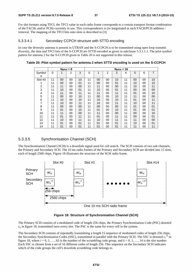
ETSI
ETSI TS 125 211 V8.7.0 (2010-10)373GPP TS 25.211 version 8.7.0 Release 8
For slot formats using TFCI, the TFCI value in each radio frame corresponds to a certain transport format combination of the FACHs and/or PCHs currently in use. This correspondence is (re-)negotiated at each FACH/PCH addition / removal. The mapping of the TFCI bits onto slots is described in [3].
5.3.3.4.1 Secondary CCPCH structure with STTD encoding
In case the diversity antenna is present in UTRAN and the S-CCPCH is to be transmitted using open loop transmit diversity, the data and TFCI bits of the S-CCPCH are STTD encoded as given in subclause 5.3.1.1.1. The pilot symbol pattern for antenna 2 for the S-CCPCH given in Table 20 is not supported in this release.
Table 20: Pilot symbol pattern for antenna 2 when STTD encoding is used on the S-CCPCH
Npilot = 8 Npilot = 16 Symbol
# 0 1 2 3 0 1 2 3 4 5 6 7
Slot #0 1 2 3 4 5 6 7 8 9 10 11 12 13 14
11 11 11 11 11 11 11 11 11 11 11 11 11 11 11
00 00 11 10 11 00 10 10 00 01 11 01 10 01 01
00 00 00 00 00 00 00 00 00 00 00 00 00 00 00
10 01 00 01 11 10 10 11 00 10 00 11 11 01 01
11 11 11 11 11 11 11 11 11 11 11 11 11 11 11
00 00 11 10 11 00 10 10 00 01 11 01 10 01 01
00 00 00 00 00 00 00 00 00 00 00 00 00 00 00
10 01 00 01 11 10 10 11 00 10 00 11 11 01 01
11 11 11 11 11 11 11 11 11 11 11 11 11 11 11
00 10 10 00 01 11 01 10 01 01 00 00 11 10 11
00 00 00 00 00 00 00 00 00 00 00 00 00 00 00
10 10 11 00 10 00 11 11 01 01 10 01 00 01 11
5.3.3.5 Synchronisation Channel (SCH)
The Synchronisation Channel (SCH) is a downlink signal used for cell search. The SCH consists of two sub channels, the Primary and Secondary SCH. The 10 ms radio frames of the Primary and Secondary SCH are divided into 15 slots, each of length 2560 chips. Figure 18 illustrates the structure of the SCH radio frame.
PrimarySCH
SecondarySCH
256 chips
2560 chips
One 10 ms SCH radio frame
acsi,0
acp
acsi,1
acp
acsi,14
acp
Slot #0 Slot #1 Slot #14
Figure 18: Structure of Synchronisation Channel (SCH)
The Primary SCH consists of a modulated code of length 256 chips, the Primary Synchronisation Code (PSC) denoted cp in figure 18, transmitted once every slot. The PSC is the same for every cell in the system.
The Secondary SCH consists of repeatedly transmitting a length 15 sequence of modulated codes of length 256 chips, the Secondary Synchronisation Codes (SSC), transmitted in parallel with the Primary SCH. The SSC is denoted cs
i,k in figure 18, where i = 0, 1, …, 63 is the number of the scrambling code group, and k = 0, 1, …, 14 is the slot number. Each SSC is chosen from a set of 16 different codes of length 256. This sequence on the Secondary SCH indicates which of the code groups the cell's downlink scrambling code belongs to.
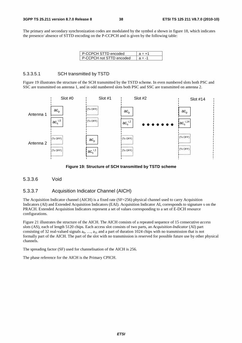
ETSI
ETSI TS 125 211 V8.7.0 (2010-10)383GPP TS 25.211 version 8.7.0 Release 8
The primary and secondary synchronization codes are modulated by the symbol a shown in figure 18, which indicates the presence/ absence of STTD encoding on the P-CCPCH and is given by the following table:
P-CCPCH STTD encoded a = +1 P-CCPCH not STTD encoded a = -1
5.3.3.5.1 SCH transmitted by TSTD
Figure 19 illustrates the structure of the SCH transmitted by the TSTD scheme. In even numbered slots both PSC and SSC are transmitted on antenna 1, and in odd numbered slots both PSC and SSC are transmitted on antenna 2.
Antenna 1
Antenna 2
acsi,0
acp
acsi,1
acp
acsi,14
acp
Slot #0 Slot #1 Slot #14
acsi,2
acp
Slot #2
(Tx OFF)
(Tx OFF)
(Tx OFF)
(Tx OFF)
(Tx OFF)
(Tx OFF)
(Tx OFF)
(Tx OFF)
Figure 19: Structure of SCH transmitted by TSTD scheme
5.3.3.6 Void
5.3.3.7 Acquisition Indicator Channel (AICH)
The Acquisition Indicator channel (AICH) is a fixed rate (SF=256) physical channel used to carry Acquisition Indicators (AI) and Extended Acquisition Indicators (EAI). Acquisition Indicator AIs corresponds to signature s on the PRACH. Extended Acquisition Indicators represent a set of values corresponding to a set of E-DCH resource configurations.
Figure 21 illustrates the structure of the AICH. The AICH consists of a repeated sequence of 15 consecutive access slots (AS), each of length 5120 chips. Each access slot consists of two parts, an Acquisition-Indicator (AI) part consisting of 32 real-valued signals a0, …, a31 and a part of duration 1024 chips with no transmission that is not formally part of the AICH. The part of the slot with no transmission is reserved for possible future use by other physical channels.
The spreading factor (SF) used for channelisation of the AICH is 256.
The phase reference for the AICH is the Primary CPICH.
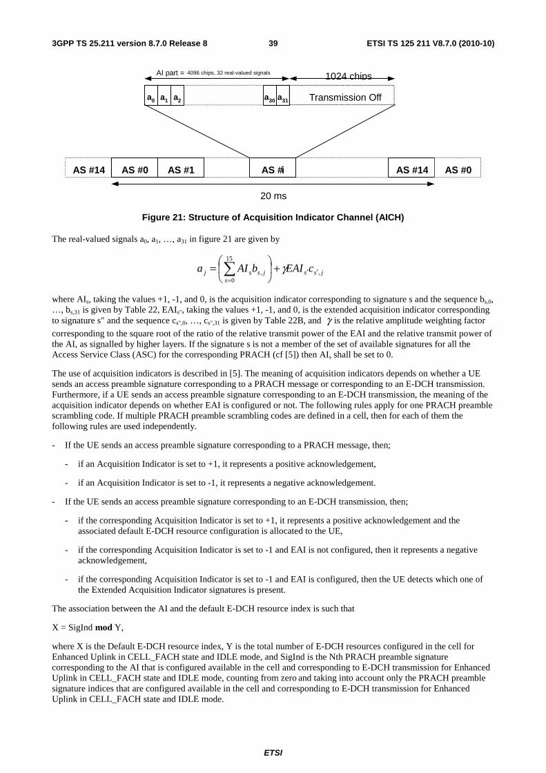
ETSI
ETSI TS 125 211 V8.7.0 (2010-10)393GPP TS 25.211 version 8.7.0 Release 8
1024 chips
Transmission Off
AS #14 AS #0 AS #1 AS # i AS #14 AS #0
a 1 a 2 a 0 a 31 a 30
AI part =
4096 chips, 32 real-valued signals
20 ms
Figure 21: Structure of Acquisition Indicator Channel (AICH)
The real-valued signals a0, a1, …, a31 in figure 21 are given by
jssjs
ssj cEAIbAIa ,,
15
0′′
=
+⎟⎠
⎞⎜⎝
⎛= ∑ γ
where AIs, taking the values +1, -1, and 0, is the acquisition indicator corresponding to signature s and the sequence bs,0, …, bs,31 is given by Table 22, EAIs", taking the values +1, -1, and 0, is the extended acquisition indicator corresponding to signature s" and the sequence cs",0, …, cs",31 is given by Table 22B, and γ is the relative amplitude weighting factor
corresponding to the square root of the ratio of the relative transmit power of the EAI and the relative transmit power of the AI, as signalled by higher layers. If the signature s is not a member of the set of available signatures for all the Access Service Class (ASC) for the corresponding PRACH (cf [5]) then AIs shall be set to 0.
The use of acquisition indicators is described in [5]. The meaning of acquisition indicators depends on whether a UE sends an access preamble signature corresponding to a PRACH message or corresponding to an E-DCH transmission. Furthermore, if a UE sends an access preamble signature corresponding to an E-DCH transmission, the meaning of the acquisition indicator depends on whether EAI is configured or not. The following rules apply for one PRACH preamble scrambling code. If multiple PRACH preamble scrambling codes are defined in a cell, then for each of them the following rules are used independently.
- If the UE sends an access preamble signature corresponding to a PRACH message, then;
- if an Acquisition Indicator is set to +1, it represents a positive acknowledgement,
- if an Acquisition Indicator is set to -1, it represents a negative acknowledgement.
- If the UE sends an access preamble signature corresponding to an E-DCH transmission, then;
- if the corresponding Acquisition Indicator is set to +1, it represents a positive acknowledgement and the associated default E-DCH resource configuration is allocated to the UE,
- if the corresponding Acquisition Indicator is set to -1 and EAI is not configured, then it represents a negative acknowledgement,
- if the corresponding Acquisition Indicator is set to -1 and EAI is configured, then the UE detects which one of the Extended Acquisition Indicator signatures is present.
The association between the AI and the default E-DCH resource index is such that
X = SigInd mod Y,
where X is the Default E-DCH resource index, Y is the total number of E-DCH resources configured in the cell for Enhanced Uplink in CELL_FACH state and IDLE mode, and SigInd is the Nth PRACH preamble signature corresponding to the AI that is configured available in the cell and corresponding to E-DCH transmission for Enhanced Uplink in CELL_FACH state and IDLE mode, counting from zero and taking into account only the PRACH preamble signature indices that are configured available in the cell and corresponding to E-DCH transmission for Enhanced Uplink in CELL_FACH state and IDLE mode.
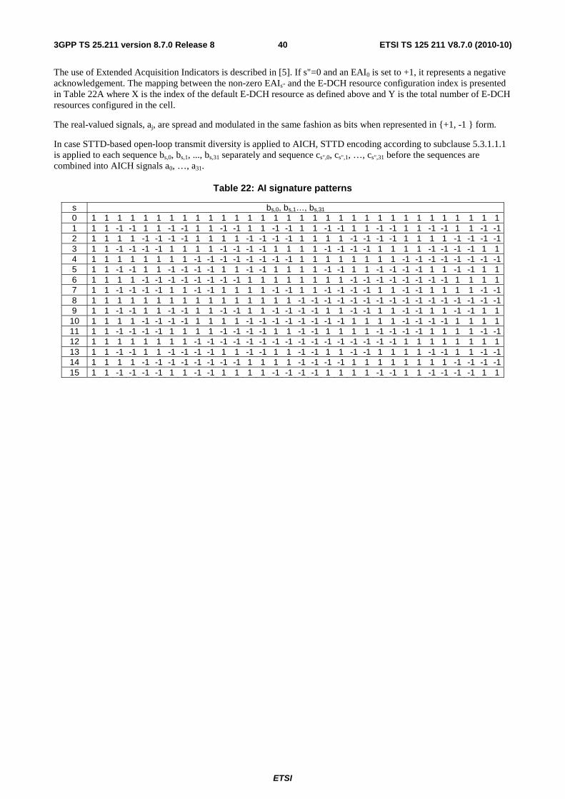
ETSI
ETSI TS 125 211 V8.7.0 (2010-10)403GPP TS 25.211 version 8.7.0 Release 8
The use of Extended Acquisition Indicators is described in [5]. If s"=0 and an EAI0 is set to +1, it represents a negative acknowledgement. The mapping between the non-zero EAIs" and the E-DCH resource configuration index is presented in Table 22A where X is the index of the default E-DCH resource as defined above and Y is the total number of E-DCH resources configured in the cell.
The real-valued signals, aj, are spread and modulated in the same fashion as bits when represented in {+1, -1 } form.
In case STTD-based open-loop transmit diversity is applied to AICH, STTD encoding according to subclause 5.3.1.1.1 is applied to each sequence bs,0, bs,1, ..., bs,31 separately and sequence cs",0, cs",1, …, cs",31 before the sequences are combined into AICH signals a0, …, a31.
Table 22: AI signature patterns
s bs,0, bs,1…, bs,31 0 1 1 1 1 1 1 1 1 1 1 1 1 1 1 1 1 1 1 1 1 1 1 1 1 1 1 1 1 1 1 1 1 1 1 1 -1 -1 1 1 -1 -1 1 1 -1 -1 1 1 -1 -1 1 1 -1 -1 1 1 -1 -1 1 1 -1 -1 1 1 -1 -1 2 1 1 1 1 -1 -1 -1 -1 1 1 1 1 -1 -1 -1 -1 1 1 1 1 -1 -1 -1 -1 1 1 1 1 -1 -1 -1 -1 3 1 1 -1 -1 -1 -1 1 1 1 1 -1 -1 -1 -1 1 1 1 1 -1 -1 -1 -1 1 1 1 1 -1 -1 -1 -1 1 1 4 1 1 1 1 1 1 1 1 -1 -1 -1 -1 -1 -1 -1 -1 1 1 1 1 1 1 1 1 -1 -1 -1 -1 -1 -1 -1 -1 5 1 1 -1 -1 1 1 -1 -1 -1 -1 1 1 -1 -1 1 1 1 1 -1 -1 1 1 -1 -1 -1 -1 1 1 -1 -1 1 1 6 1 1 1 1 -1 -1 -1 -1 -1 -1 -1 -1 1 1 1 1 1 1 1 1 -1 -1 -1 -1 -1 -1 -1 -1 1 1 1 1 7 1 1 -1 -1 -1 -1 1 1 -1 -1 1 1 1 1 -1 -1 1 1 -1 -1 -1 -1 1 1 -1 -1 1 1 1 1 -1 -1 8 1 1 1 1 1 1 1 1 1 1 1 1 1 1 1 1 -1 -1 -1 -1 -1 -1 -1 -1 -1 -1 -1 -1 -1 -1 -1 -1 9 1 1 -1 -1 1 1 -1 -1 1 1 -1 -1 1 1 -1 -1 -1 -1 1 1 -1 -1 1 1 -1 -1 1 1 -1 -1 1 1 10 1 1 1 1 -1 -1 -1 -1 1 1 1 1 -1 -1 -1 -1 -1 -1 -1 -1 1 1 1 1 -1 -1 -1 -1 1 1 1 1 11 1 1 -1 -1 -1 -1 1 1 1 1 -1 -1 -1 -1 1 1 -1 -1 1 1 1 1 -1 -1 -1 -1 1 1 1 1 -1 -1 12 1 1 1 1 1 1 1 1 -1 -1 -1 -1 -1 -1 -1 -1 -1 -1 -1 -1 -1 -1 -1 -1 1 1 1 1 1 1 1 1 13 1 1 -1 -1 1 1 -1 -1 -1 -1 1 1 -1 -1 1 1 -1 -1 1 1 -1 -1 1 1 1 1 -1 -1 1 1 -1 -1 14 1 1 1 1 -1 -1 -1 -1 -1 -1 -1 -1 1 1 1 1 -1 -1 -1 -1 1 1 1 1 1 1 1 1 -1 -1 -1 -1 15 1 1 -1 -1 -1 -1 1 1 -1 -1 1 1 1 1 -1 -1 -1 -1 1 1 1 1 -1 -1 1 1 -1 -1 -1 -1 1 1
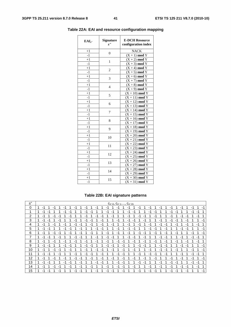
ETSI
ETSI TS 125 211 V8.7.0 (2010-10)413GPP TS 25.211 version 8.7.0 Release 8
Table 22A: EAI and resource configuration mapping
EAIs" Signature s"
E-DCH Resource configuration index
+1 0
NACK -1 (X + 1) mod Y +1
1 (X + 2) mod Y
-1 (X + 3) mod Y +1
2 (X + 4) mod Y
-1 (X + 5) mod Y +1
3 (X + 6) mod Y
-1 (X + 7) mod Y +1
4 (X + 8) mod Y
-1 (X + 9) mod Y +1
5 (X + 10) mod Y
-1 (X + 11) mod Y +1
6 (X + 12) mod Y
-1 (X + 13) mod Y +1
7 (X + 14) mod Y
-1 (X + 15) mod Y +1
8 (X + 16) mod Y
-1 (X + 17) mod Y +1
9 (X + 18) mod Y
-1 (X + 19) mod Y +1
10 (X + 20) mod Y
-1 (X + 21) mod Y +1
11 (X + 22) mod Y
-1 (X + 23) mod Y +1
12 (X + 24) mod Y
-1 (X + 25) mod Y +1
13 (X + 26) mod Y
-1 (X + 27) mod Y +1
14 (X + 28) mod Y
-1 (X + 29) mod Y +1
15 (X + 30) mod Y
-1 (X + 31) mod Y
Table 22B: EAI signature patterns
s" cs",0, cs",1…, cs",31 0 1 -1 1 -1 1 -1 1 -1 1 -1 1 -1 1 -1 1 -1 1 -1 1 -1 1 -1 1 -1 1 -1 1 -1 1 -1 1 -1 1 1 -1 -1 1 1 -1 -1 1 1 -1 -1 1 1 -1 -1 1 1 -1 -1 1 1 -1 -1 1 1 -1 -1 1 1 -1 -1 1 2 1 -1 1 -1 -1 1 -1 1 1 -1 1 -1 -1 1 -1 1 1 -1 1 -1 -1 1 -1 1 1 -1 1 -1 -1 1 -1 1 3 1 -1 -1 1 -1 1 1 -1 1 -1 -1 1 -1 1 1 -1 1 -1 -1 1 -1 1 1 -1 1 -1 -1 1 -1 1 1 -1 4 1 -1 1 -1 1 -1 1 -1 -1 1 -1 1 -1 1 -1 1 1 -1 1 -1 1 -1 1 -1 -1 1 -1 1 -1 1 -1 1 5 1 -1 -1 1 1 -1 -1 1 -1 1 1 -1 -1 1 1 -1 1 -1 -1 1 1 -1 -1 1 -1 1 1 -1 -1 1 1 -1 6 1 -1 1 -1 -1 1 -1 1 -1 1 -1 1 1 -1 1 -1 1 -1 1 -1 -1 1 -1 1 -1 1 -1 1 1 -1 1 -1 7 1 -1 -1 1 -1 1 1 -1 -1 1 1 -1 1 -1 -1 1 1 -1 -1 1 -1 1 1 -1 -1 1 1 -1 1 -1 -1 1 8 1 -1 1 -1 1 -1 1 -1 1 -1 1 -1 1 -1 1 -1 -1 1 -1 1 -1 1 -1 1 -1 1 -1 1 -1 1 -1 1 9 1 -1 -1 1 1 -1 -1 1 1 -1 -1 1 1 -1 -1 1 -1 1 1 -1 -1 1 1 -1 -1 1 1 -1 -1 1 1 -1 10 1 -1 1 -1 -1 1 -1 1 1 -1 1 -1 -1 1 -1 1 -1 1 -1 1 1 -1 1 -1 -1 1 -1 1 1 -1 1 -1 11 1 -1 -1 1 -1 1 1 -1 1 -1 -1 1 -1 1 1 -1 -1 1 1 -1 1 -1 -1 1 -1 1 1 -1 1 -1 -1 1 12 1 -1 1 -1 1 -1 1 -1 -1 1 -1 1 -1 1 -1 1 -1 1 -1 1 -1 1 -1 1 1 -1 1 -1 1 -1 1 -1 13 1 -1 -1 1 1 -1 -1 1 -1 1 1 -1 -1 1 1 -1 -1 1 1 -1 -1 1 1 -1 1 -1 -1 1 1 -1 -1 1 14 1 -1 1 -1 -1 1 -1 1 -1 1 -1 1 1 -1 1 -1 -1 1 -1 1 1 -1 1 -1 1 -1 1 -1 -1 1 -1 1 15 1 -1 -1 1 -1 1 1 -1 -1 1 1 -1 1 -1 -1 1 -1 1 1 -1 1 -1 -1 1 1 -1 -1 1 -1 1 1 -1
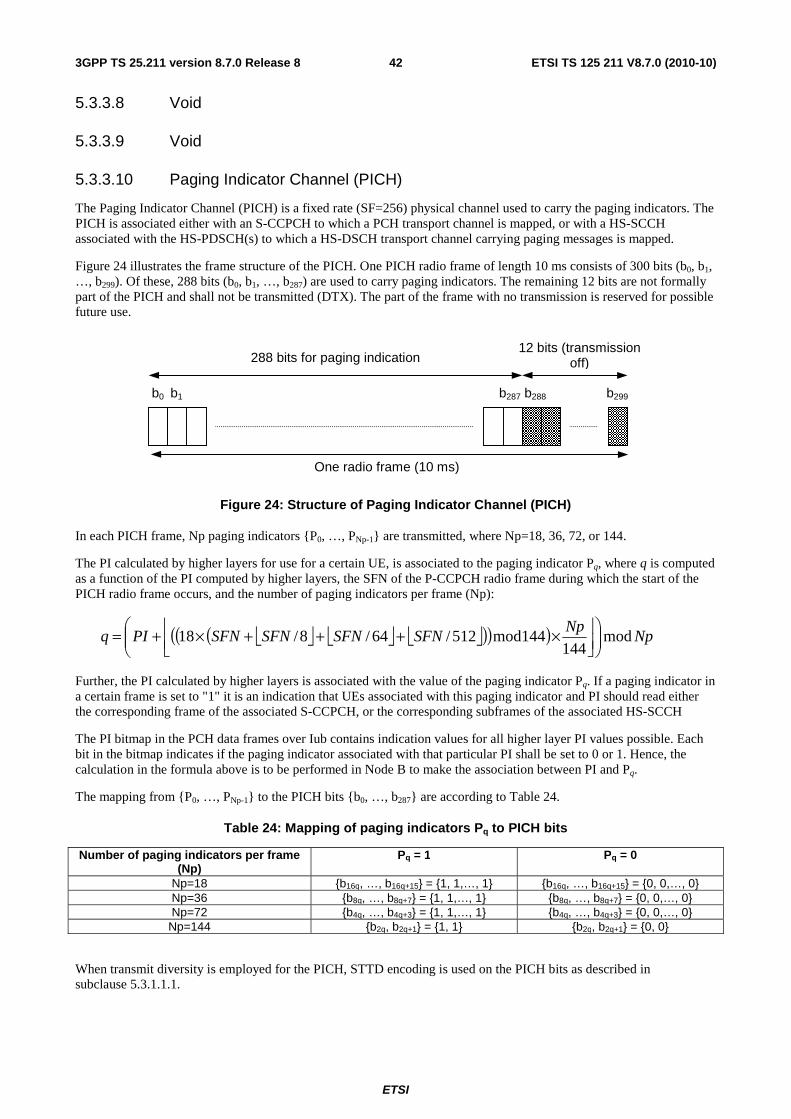
ETSI
ETSI TS 125 211 V8.7.0 (2010-10)423GPP TS 25.211 version 8.7.0 Release 8
5.3.3.8 Void
5.3.3.9 Void
5.3.3.10 Paging Indicator Channel (PICH)
The Paging Indicator Channel (PICH) is a fixed rate (SF=256) physical channel used to carry the paging indicators. The PICH is associated either with an S-CCPCH to which a PCH transport channel is mapped, or with a HS-SCCH associated with the HS-PDSCH(s) to which a HS-DSCH transport channel carrying paging messages is mapped.
Figure 24 illustrates the frame structure of the PICH. One PICH radio frame of length 10 ms consists of 300 bits (b0, b1, …, b299). Of these, 288 bits (b0, b1, …, b287) are used to carry paging indicators. The remaining 12 bits are not formally part of the PICH and shall not be transmitted (DTX). The part of the frame with no transmission is reserved for possible future use.
b1b0
288 bits for paging indication12 bits (transmission
off)
One radio frame (10 ms)
b287 b288 b299
Figure 24: Structure of Paging Indicator Channel (PICH)
In each PICH frame, Np paging indicators {P0, …, PNp-1} are transmitted, where Np=18, 36, 72, or 144.
The PI calculated by higher layers for use for a certain UE, is associated to the paging indicator Pq, where q is computed as a function of the PI computed by higher layers, the SFN of the P-CCPCH radio frame during which the start of the PICH radio frame occurs, and the number of paging indicators per frame (Np):
⎣ ⎦ ⎣ ⎦ ⎣ ⎦( )( )( ) Np
NpSFNSFNSFNSFNPIq mod
144144mod512/64/8/18 ⎟⎟
⎠
⎞⎜⎜⎝
⎛⎥⎦
⎥⎢⎣
⎢ ×+++×+=
Further, the PI calculated by higher layers is associated with the value of the paging indicator Pq. If a paging indicator in a certain frame is set to "1" it is an indication that UEs associated with this paging indicator and PI should read either the corresponding frame of the associated S-CCPCH, or the corresponding subframes of the associated HS-SCCH
The PI bitmap in the PCH data frames over Iub contains indication values for all higher layer PI values possible. Each bit in the bitmap indicates if the paging indicator associated with that particular PI shall be set to 0 or 1. Hence, the calculation in the formula above is to be performed in Node B to make the association between PI and Pq.
The mapping from {P0, …, PNp-1} to the PICH bits {b0, …, b287} are according to Table 24.
Table 24: Mapping of paging indicators Pq to PICH bits
Number of paging indicators per frame (Np)
Pq = 1 Pq = 0
Np=18 {b16q, …, b16q+15} = {1, 1,…, 1} {b16q, …, b16q+15} = {0, 0,…, 0} Np=36 {b8q, …, b8q+7} = {1, 1,…, 1} {b8q, …, b8q+7} = {0, 0,…, 0} Np=72 {b4q, …, b4q+3} = {1, 1,…, 1} {b4q, …, b4q+3} = {0, 0,…, 0}
Np=144 {b2q, b2q+1} = {1, 1} {b2q, b2q+1} = {0, 0}
When transmit diversity is employed for the PICH, STTD encoding is used on the PICH bits as described in subclause 5.3.1.1.1.
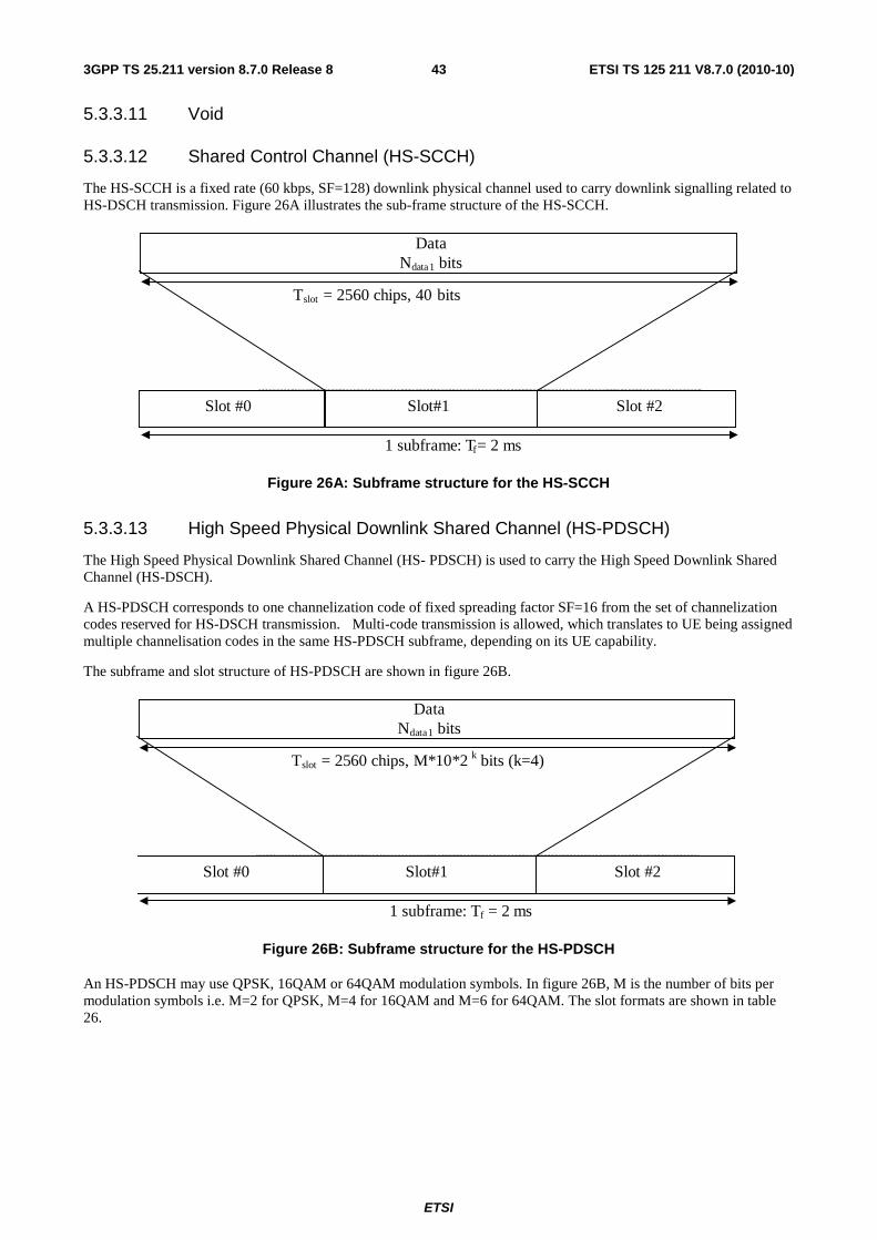
ETSI
ETSI TS 125 211 V8.7.0 (2010-10)433GPP TS 25.211 version 8.7.0 Release 8
5.3.3.11 Void
5.3.3.12 Shared Control Channel (HS-SCCH)
The HS-SCCH is a fixed rate (60 kbps, SF=128) downlink physical channel used to carry downlink signalling related to HS-DSCH transmission. Figure 26A illustrates the sub-frame structure of the HS-SCCH.
Slot #0 Slot#1 Slot #2
T slot = 2560 chips, 40 bits
Data N data 1 bits
1 subframe: T f = 2 ms
Figure 26A: Subframe structure for the HS-SCCH
5.3.3.13 High Speed Physical Downlink Shared Channel (HS-PDSCH)
The High Speed Physical Downlink Shared Channel (HS- PDSCH) is used to carry the High Speed Downlink Shared Channel (HS-DSCH).
A HS-PDSCH corresponds to one channelization code of fixed spreading factor SF=16 from the set of channelization codes reserved for HS-DSCH transmission. Multi-code transmission is allowed, which translates to UE being assigned multiple channelisation codes in the same HS-PDSCH subframe, depending on its UE capability.
The subframe and slot structure of HS-PDSCH are shown in figure 26B.
Slot #0 Slot#1 Slot #2
T slot = 2560 chips, M*10*2 k bits (k=4)
Data N data 1 bits
1 subframe: T f = 2 ms
Figure 26B: Subframe structure for the HS-PDSCH
An HS-PDSCH may use QPSK, 16QAM or 64QAM modulation symbols. In figure 26B, M is the number of bits per modulation symbols i.e. M=2 for QPSK, M=4 for 16QAM and M=6 for 64QAM. The slot formats are shown in table 26.
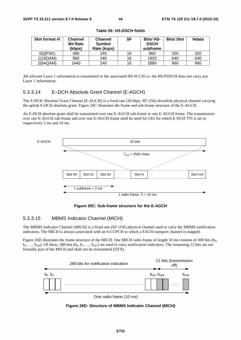
ETSI
ETSI TS 125 211 V8.7.0 (2010-10)443GPP TS 25.211 version 8.7.0 Release 8
Table 26: HS-DSCH fields
Slot format #i Channel Bit Rate (kbps)
Channel Symbol
Rate (ksps)
SF Bits/ HS-DSCH
subframe
Bits/ Slot Ndata
0(QPSK) 480 240 16 960 320 320 1(16QAM) 960 240 16 1920 640 640 2(64QAM) 1440 240 16 2880 960 960
All relevant Layer 1 information is transmitted in the associated HS-SCCH i.e. the HS-PDSCH does not carry any Layer 1 information.
5.3.3.14 E–DCH Absolute Grant Channel (E-AGCH)
The E-DCH Absolute Grant Channel (E-AGCH) is a fixed rate (30 kbps, SF=256) downlink physical channel carrying the uplink E-DCH absolute grant. Figure 26C illustrates the frame and sub-frame structure of the E-AGCH.
An E-DCH absolute grant shall be transmitted over one E-AGCH sub-frame or one E-AGCH frame. The transmission over one E-AGCH sub-frame and over one E-AGCH frame shall be used for UEs for which E-DCH TTI is set to respectively 2 ms and 10 ms.
Slot #1 Slot #14 Slot #2 Slot #i Slot #0
Tslot = 2560 chips
1 subframe = 2 ms
1 radio frame, Tf = 10 ms
E-AGCH 20 bits
Figure 26C: Sub-frame structure for the E-AGCH
5.3.3.15 MBMS Indicator Channel (MICH)
The MBMS Indicator Channel (MICH) is a fixed rate (SF=256) physical channel used to carry the MBMS notification indicators. The MICH is always associated with an S-CCPCH to which a FACH transport channel is mapped.
Figure 26D illustrates the frame structure of the MICH. One MICH radio frame of length 10 ms consists of 300 bits (b0, b1, …, b299). Of these, 288 bits (b0, b1, …, b287) are used to carry notification indicators. The remaining 12 bits are not formally part of the MICH and shall not be transmitted (DTX).
b1b0
288 bits for notification indication12 bits (transmission
off)
One radio frame (10 ms)
b287 b288 b299
Figure 26D: Structure of MBMS Indicator Channel (MICH)
ETSI
ETSI TS 125 211 V8.7.0 (2010-10)453GPP TS 25.211 version 8.7.0 Release 8
In each MICH frame, Nn notification indicators {N0, …, NNn-1} are transmitted, where Nn=18, 36, 72, or 144.
The NI calculated by higher layers is associated to the index q of the notification indicator Nq, where q is computed as a function of the NI computed by higher layers, the SFN of the P-CCPCH radio frame during which the start of the MICH radio frame occurs, and the number of notification indicators per frame (Nn):
( )( )( )( )( ) ⎥⎦
⎥⎢⎣
⎢ ××⊕×=G
NnGGSFNCCq modmodNI
where G = 216 , C = 25033 and NI is the 16 bit Notification Indicator calculated by higher layers.
The set of NI signalled over Iub indicates all higher layer NI values for which the associated notification indicator on MICH shall be set to 1 during the corresponding modification period. Hence, the calculation in the formula above shall be performed in the Node B every MICH frame for each NI signalled over Iub to make the association between NI and q and set the related Nq to 1. All other notification indicators on MICH shall be set to 0.
The mapping from {N0, …, NNn-1} to the MICH bits {b0, …, b287} are according to table 27.
Table 27: Mapping of notification indicators Nq to MICH bits
Number of notification indicators per frame
(Nn)
Nq = 1 Nq = 0
Nn=18 {b16q, …, b16q+15} = {1, 1,…, 1} {b16q, …, b16q+15} = {0, 0,…, 0} Nn=36 {b8q, …, b8q+7} = {1, 1,…, 1} {b8q, …, b8q+7} = {0, 0,…, 0} Nn=72 {b4q, …, b4q+3} = {1, 1,…, 1} {b4q, …, b4q+3} = {0, 0,…, 0}
Nn=144 {b2q, b2q+1} = {1, 1} {b2q, b2q+1} = {0, 0}
When transmit diversity is employed for the MICH, STTD encoding is used on the MICH bits as described in subclause 5.3.1.1.1.
6 Mapping and association of physical channels
6.1 Mapping of transport channels onto physical channels Figure 27 summarises the mapping of transport channels onto physical channels.
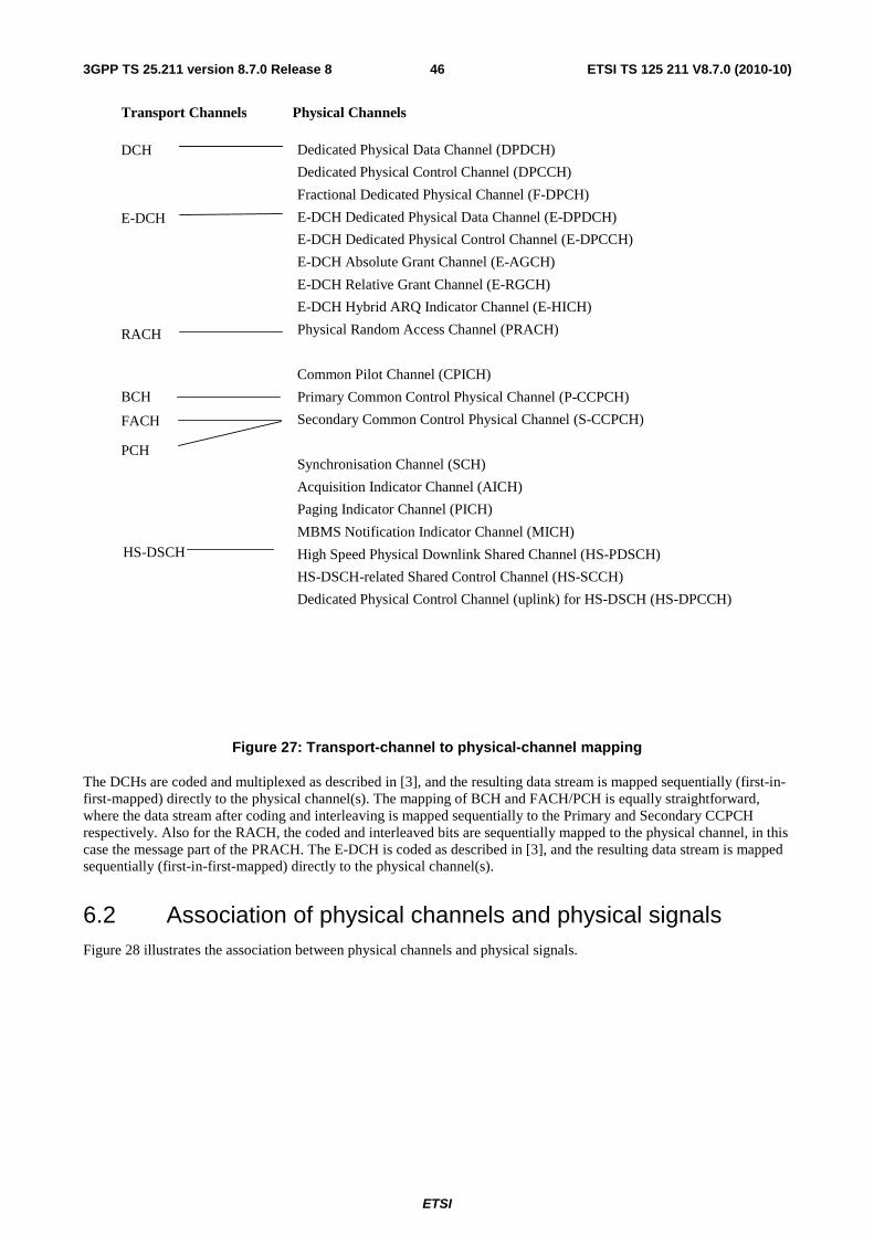
ETSI
ETSI TS 125 211 V8.7.0 (2010-10)463GPP TS 25.211 version 8.7.0 Release 8
Dedicated Physical Data Channel (DPDCH)
Dedicated Physical Control Channel (DPCCH)
Fractional Dedicated Physical Channel (F-DPCH)
E-DCH Dedicated Physical Data Channel (E-DPDCH)
E-DCH Dedicated Physical Control Channel (E-DPCCH)
E-DCH Absolute Grant Channel (E-AGCH)
E-DCH Relative Grant Channel (E-RGCH)
E-DCH Hybrid ARQ Indicator Channel (E-HICH)
Physical Random Access Channel (PRACH)
Common Pilot Channel (CPICH)
Primary Common Control Physical Channel (P-CCPCH)
Secondary Common Control Physical Channel (S-CCPCH)
Synchronisation Channel (SCH)
Acquisition Indicator Channel (AICH)
Paging Indicator Channel (PICH)
MBMS Notification Indicator Channel (MICH)
High Speed Physical Downlink Shared Channel (HS-PDSCH)
HS-DSCH-related Shared Control Channel (HS-SCCH)
Dedicated Physical Control Channel (uplink) for HS-DSCH (HS-DPCCH)
Transport Channels
DCH
RACH
BCH
FACH
PCH
Physical Channels
HS-DSCH
E-DCH
Figure 27: Transport-channel to physical-channel mapping
The DCHs are coded and multiplexed as described in [3], and the resulting data stream is mapped sequentially (first-in-first-mapped) directly to the physical channel(s). The mapping of BCH and FACH/PCH is equally straightforward, where the data stream after coding and interleaving is mapped sequentially to the Primary and Secondary CCPCH respectively. Also for the RACH, the coded and interleaved bits are sequentially mapped to the physical channel, in this case the message part of the PRACH. The E-DCH is coded as described in [3], and the resulting data stream is mapped sequentially (first-in-first-mapped) directly to the physical channel(s).
6.2 Association of physical channels and physical signals Figure 28 illustrates the association between physical channels and physical signals.
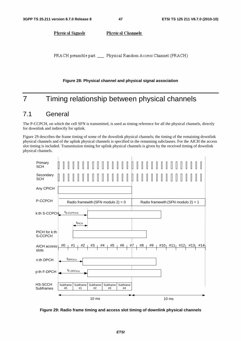
ETSI
ETSI TS 125 211 V8.7.0 (2010-10)473GPP TS 25.211 version 8.7.0 Release 8
Figure 28: Physical channel and physical signal association
7 Timing relationship between physical channels
7.1 General The P-CCPCH, on which the cell SFN is transmitted, is used as timing reference for all the physical channels, directly for downlink and indirectly for uplink.
Figure 29 describes the frame timing of some of the downlink physical channels; the timing of the remaining downlink physical channels and of the uplink physical channels is specified in the remaining subclauses. For the AICH the access slot timing is included. Transmission timing for uplink physical channels is given by the received timing of downlink physical channels.
k:th S-CCPCH
AICH access slots
SecondarySCH
PrimarySCH
τ S-CCPCH,k
10 ms
τ PICH
#0 #1 #2 #3 #14#13#12#11#10#9#8#7#6#5#4
Radio frame with (SFN modulo 2) = 0 Radio frame with (SFN modulo 2) = 1
τ DPCH,n
P-CCPCH
Any CPICH
PICH for k:thS-CCPCH
n:th DPCH
10 ms
Subframe # 0
HS-SCCH Subframes
Subframe # 1
Subframe # 2
Subframe #3
Subframe # 4
τ F-DPCH,p p:th F-DPCH
Figure 29: Radio frame timing and access slot timing of downlink physical channels
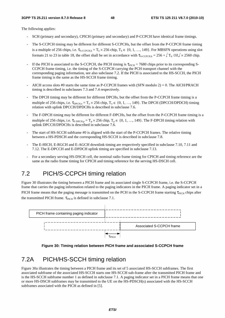
ETSI
ETSI TS 125 211 V8.7.0 (2010-10)483GPP TS 25.211 version 8.7.0 Release 8
The following applies:
- SCH (primary and secondary), CPICH (primary and secondary) and P-CCPCH have identical frame timings.
- The S-CCPCH timing may be different for different S-CCPCHs, but the offset from the P-CCPCH frame timing
is a multiple of 256 chips, i.e. τS-CCPCH,k = Tk × 256 chip, Tk ∈ {0, 1, …, 149}. For MBSFN operations using slot
formats 21 to 23 in table 18, the offset shall be set in accordance with τS-CCPCH,k = 256 + ⎣ Tk /10⎦. × 2560 chip.
- If the PICH is associated to the S-CCPCH, the PICH timing is τPICH = 7680 chips prior to its corresponding S-CCPCH frame timing, i.e. the timing of the S-CCPCH carrying the PCH transport channel with the corresponding paging information, see also subclause 7.2. If the PICH is associated to the HS-SCCH, the PICH frame timing is the same as the HS-SCCH frame timing.
- AICH access slots #0 starts the same time as P-CCPCH frames with (SFN modulo 2) = 0. The AICH/PRACH timing is described in subclauses 7.3 and 7.4 respectively.
- The DPCH timing may be different for different DPCHs, but the offset from the P-CCPCH frame timing is a
multiple of 256 chips, i.e. τDPCH,n = Tn × 256 chip, Tn ∈ {0, 1, …, 149}. The DPCH (DPCCH/DPDCH) timing relation with uplink DPCCH/DPDCHs is described in subclause 7.6.
- The F-DPCH timing may be different for different F-DPCHs, but the offset from the P-CCPCH frame timing is a
multiple of 256 chips, i.e. τF-DPCH,p = Tp × 256 chip, Tp ∈ {0, 1, …, 149}. The F-DPCH timing relation with uplink DPCCH/DPDCHs is described in subclause 7.6.
- The start of HS-SCCH subframe #0 is aligned with the start of the P-CCPCH frames. The relative timing between a HS-PDSCH and the corresponding HS-SCCH is described in subclause 7.8.
- The E-HICH, E-RGCH and E-AGCH downlink timing are respectively specified in subclause 7.10, 7.11 and 7.12. The E-DPCCH and E-DPDCH uplink timing are specified in subclause 7.13.
- For a secondary serving HS-DSCH cell, the nominal radio frame timing for CPICH and timing reference are the same as the radio frame timing for CPICH and timing reference for the serving HS-DSCH cell.
7.2 PICH/S-CCPCH timing relation Figure 30 illustrates the timing between a PICH frame and its associated single S-CCPCH frame, i.e. the S-CCPCH frame that carries the paging information related to the paging indicators in the PICH frame. A paging indicator set in a
PICH frame means that the paging message is transmitted on the PCH in the S-CCPCH frame starting τPICH chips after
the transmitted PICH frame. τPICH is defined in subclause 7.1.
τPICH
Associated S-CCPCH frame
PICH frame containing paging indicator
Figure 30: Timing relation between PICH frame and associated S-CCPCH frame
7.2A PICH/HS-SCCH timing relation Figure 30a illustrates the timing between a PICH frame and its set of 5 associated HS-SCCH subframes. The first associated subframe of the associated HS-SCCH starts one HS-SCCH sub-frame after the transmitted PICH frame and is the HS-SCCH subframe number 1 as defined in subclause 7.1. A paging indicator set in a PICH frame means that one or more HS-DSCH subframes may be transmitted to the UE on the HS-PDSCH(s) associated with the HS-SCCH subframes associated with the PICH as defined in [5].
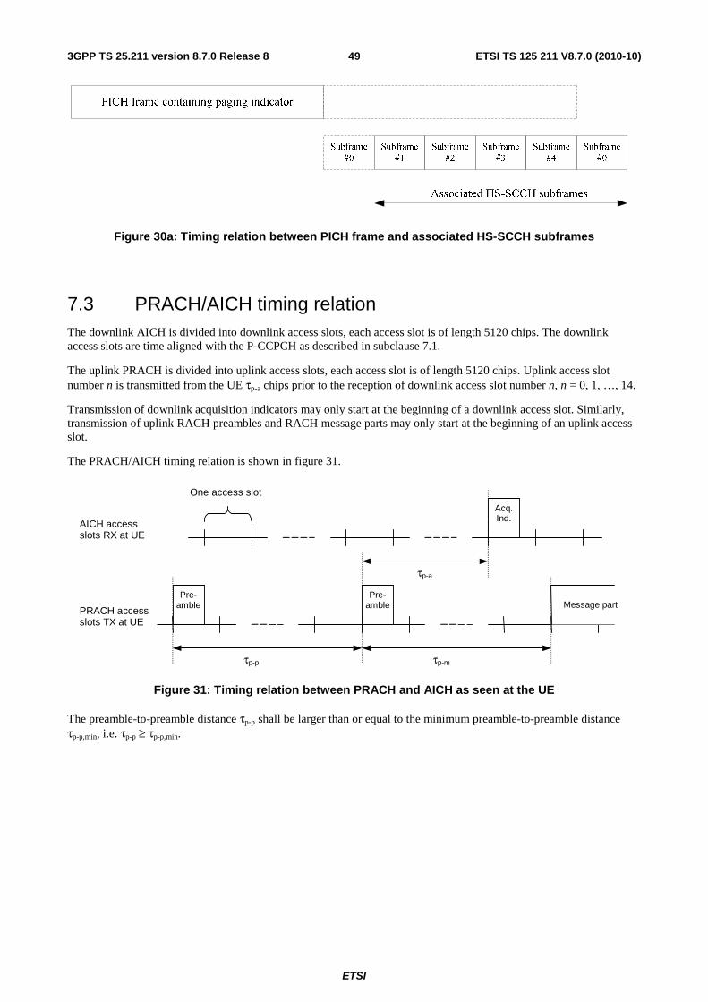
ETSI
ETSI TS 125 211 V8.7.0 (2010-10)493GPP TS 25.211 version 8.7.0 Release 8
Figure 30a: Timing relation between PICH frame and associated HS-SCCH subframes
7.3 PRACH/AICH timing relation The downlink AICH is divided into downlink access slots, each access slot is of length 5120 chips. The downlink access slots are time aligned with the P-CCPCH as described in subclause 7.1.
The uplink PRACH is divided into uplink access slots, each access slot is of length 5120 chips. Uplink access slot number n is transmitted from the UE τp-a chips prior to the reception of downlink access slot number n, n = 0, 1, …, 14.
Transmission of downlink acquisition indicators may only start at the beginning of a downlink access slot. Similarly, transmission of uplink RACH preambles and RACH message parts may only start at the beginning of an uplink access slot.
The PRACH/AICH timing relation is shown in figure 31.
One access slot
τp-a
τp-mτp-p
Pre-amble
Pre-amble Message part
Acq.Ind.
AICH accessslots RX at UE
PRACH accessslots TX at UE
Figure 31: Timing relation between PRACH and AICH as seen at the UE
The preamble-to-preamble distance τp-p shall be larger than or equal to the minimum preamble-to-preamble distance τp-p,min, i.e. τp-p ≥ τp-p,min.
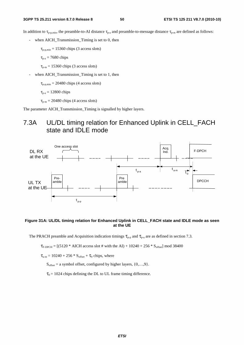
ETSI
ETSI TS 125 211 V8.7.0 (2010-10)503GPP TS 25.211 version 8.7.0 Release 8
In addition to τp-p,min, the preamble-to-AI distance τp-a and preamble-to-message distance τp-m are defined as follows:
- when AICH_Transmission_Timing is set to 0, then
τp-p,min = 15360 chips (3 access slots)
τp-a = 7680 chips
τp-m = 15360 chips (3 access slots)
- when AICH_Transmission_Timing is set to 1, then
τp-p,min = 20480 chips (4 access slots)
τp-a = 12800 chips
τp-m = 20480 chips (4 access slots)
The parameter AICH_Transmission_Timing is signalled by higher layers.
7.3A UL/DL timing relation for Enhanced Uplink in CELL_FACH state and IDLE mode
UL TX at the UE
One access slot
t p-a t a-m
t p-p
Pre- amble Pre
- amble DPCCH
Acq. Ind. DL RX
at the UE F-DPCH
t 0
Figure 31A: UL/DL timing relation for Enhanced Uplink in CELL_FACH state and IDLE mode as seen at the UE
The PRACH preamble and Acquisition indication timings τp-p and τp-a are as defined in section 7.3.
τF-DPCH = [(5120 * AICH access slot # with the AI) + 10240 + 256 * Soffset] mod 38400
τa-m = 10240 + 256 * Soffset + τ0 chips, where
Soffset = a symbol offset, configured by higher layers, {0,…,9}.
τ0 = 1024 chips defining the DL to UL frame timing difference.
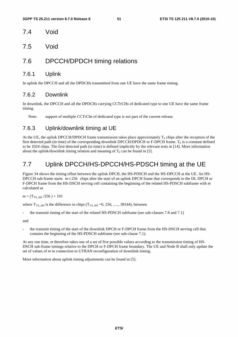
ETSI
ETSI TS 125 211 V8.7.0 (2010-10)513GPP TS 25.211 version 8.7.0 Release 8
7.4 Void
7.5 Void
7.6 DPCCH/DPDCH timing relations
7.6.1 Uplink
In uplink the DPCCH and all the DPDCHs transmitted from one UE have the same frame timing.
7.6.2 Downlink
In downlink, the DPCCH and all the DPDCHs carrying CCTrCHs of dedicated type to one UE have the same frame timing.
Note: support of multiple CCTrChs of dedicated type is not part of the current release.
7.6.3 Uplink/downlink timing at UE
At the UE, the uplink DPCCH/DPDCH frame transmission takes place approximately T0 chips after the reception of the first detected path (in time) of the corresponding downlink DPCCH/DPDCH or F-DPCH frame. T0 is a constant defined to be 1024 chips. The first detected path (in time) is defined implicitly by the relevant tests in [14]. More information about the uplink/downlink timing relation and meaning of T0 can be found in [5].
7.7 Uplink DPCCH/HS-DPCCH/HS-PDSCH timing at the UE Figure 34 shows the timing offset between the uplink DPCH, the HS-PDSCH and the HS-DPCCH at the UE. An HS-DPCCH sub-frame starts 256×m chips after the start of an uplink DPCH frame that corresponds to the DL DPCH or F-DPCH frame from the HS-DSCH serving cell containing the beginning of the related HS-PDSCH subframe with m calculated as
m = (TTX_diff /256 ) + 101
where TTX_diff is the difference in chips (TTX_diff =0, 256, ....., 38144), between
- the transmit timing of the start of the related HS-PDSCH subframe (see sub-clauses 7.8 and 7.1)
and
- the transmit timing of the start of the downlink DPCH or F-DPCH frame from the HS-DSCH serving cell that contains the beginning of the HS-PDSCH subframe (see sub-clause 7.1).
At any one time, m therefore takes one of a set of five possible values according to the transmission timing of HS-DSCH sub-frame timings relative to the DPCH or F-DPCH frame boundary. The UE and Node B shall only update the set of values of m in connection to UTRAN reconfiguration of downlink timing.
More information about uplink timing adjustments can be found in [5].
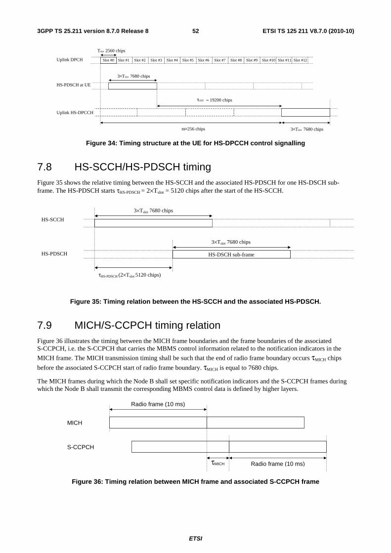
ETSI
ETSI TS 125 211 V8.7.0 (2010-10)523GPP TS 25.211 version 8.7.0 Release 8
Uplink DPCH
HS-PDSCH at UE
Uplink HS-DPCCH
3×Tslot 7680 chips
m×256 chips
τUEP ≈ 19200 chips
Tslot 2560 chips
3×Tslot 7680 chips
Slot #0 Slot #1 Slot #2 Slot #3 Slot #4 Slot #5 Slot #6 Slot #7 Slot #8 Slot #9 Slot #10 Slot #11 Slot #12
Figure 34: Timing structure at the UE for HS-DPCCH control signalling
7.8 HS-SCCH/HS-PDSCH timing Figure 35 shows the relative timing between the HS-SCCH and the associated HS-PDSCH for one HS-DSCH sub-frame. The HS-PDSCH starts τHS-PDSCH = 2×Tslot = 5120 chips after the start of the HS-SCCH.
HS-SCCH
HS-PDSCH
3×Tslot 7680 chips
τHS-PDSCH (2×Tslot 5120 chips)
3×Tslot 7680 chips
HS-DSCH sub-frame
Figure 35: Timing relation between the HS-SCCH and the associated HS-PDSCH.
7.9 MICH/S-CCPCH timing relation Figure 36 illustrates the timing between the MICH frame boundaries and the frame boundaries of the associated S-CCPCH, i.e. the S-CCPCH that carries the MBMS control information related to the notification indicators in the
MICH frame. The MICH transmission timing shall be such that the end of radio frame boundary occurs τMICH chips
before the associated S-CCPCH start of radio frame boundary. τMICH is equal to 7680 chips.
The MICH frames during which the Node B shall set specific notification indicators and the S-CCPCH frames during which the Node B shall transmit the corresponding MBMS control data is defined by higher layers.
Radio frame (10 ms)
Radio frame (10 ms) τMICH
MICH
S-CCPCH
Figure 36: Timing relation between MICH frame and associated S-CCPCH frame
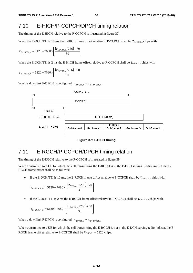
ETSI
ETSI TS 125 211 V8.7.0 (2010-10)533GPP TS 25.211 version 8.7.0 Release 8
7.10 E-HICH/P-CCPCH/DPCH timing relation The timing of the E-HICH relative to the P-CCPCH is illustrated in figure 37.
When the E-DCH TTI is 10 ms the E-HICH frame offset relative to P-CCPCH shall be τE-HICH,n chips with
( )⎥⎦
⎥⎢⎣
⎢ −×+=− 30
7025676805120 ,
,nDPCH
nHICHE
ττ
When the E-DCH TTI is 2 ms the E-HICH frame offset relative to P-CCPCH shall be τE-HICH,n chips with
( )⎥⎦
⎥⎢⎣
⎢ +×+=− 30
5025676805120 ,
,nDPCH
nHICHE
ττ
When a downlink F-DPCH is configured, nDPCHFnDPCH ,, −= ττ .
Figure 37: E-HICH timing
7.11 E-RGCH/P-CCPCH/DPCH timing relation The timing of the E-RGCH relative to the P-CCPCH is illustrated in figure 38.
When transmitted to a UE for which the cell transmitting the E-RGCH is in the E-DCH serving radio link set, the E-RGCH frame offset shall be as follows:
• if the E-DCH TTI is 10 ms, the E-RGCH frame offset relative to P-CCPCH shall be τE-RGCH,n chips with
( )⎥⎦
⎥⎢⎣
⎢ −×+=− 30
7025676805120 ,
,nDPCH
nRGCHE
ττ
• if the E-DCH TTI is 2 ms the E-RGCH frame offset relative to P-CCPCH shall be τE-RGCH,n chips with
( )⎥⎦
⎥⎢⎣
⎢ +×+=− 30
5025676805120 ,
,nDPCH
nRGCHE
ττ
When a downlink F-DPCH is configured, nDPCHFnDPCH ,, −= ττ .
When transmitted to a UE for which the cell transmitting the E-RGCH is not in the E-DCH serving radio link set, the E-
RGCH frame offset relative to P-CCPCH shall be τE-RGCH = 5120 chips.
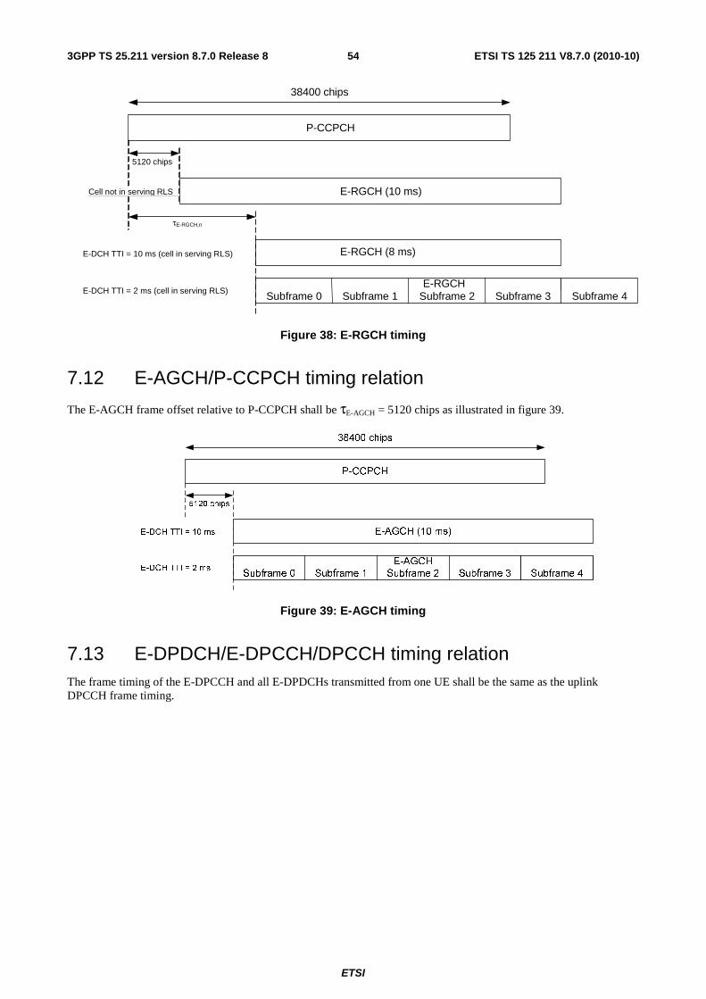
ETSI
ETSI TS 125 211 V8.7.0 (2010-10)543GPP TS 25.211 version 8.7.0 Release 8
P-CCPCH
τE-RGCH,n
38400 chips
E-DCH TTI = 10 ms (cell in serving RLS)
Subframe 0 Subframe 1 Subframe 2 Subframe 3 E-RGCH
Subframe 4
5120 chips
E-RGCH (10 ms) Cell not in serving RLS
E-DCH TTI = 2 ms (cell in serving RLS)
E-RGCH (8 ms)
Figure 38: E-RGCH timing
7.12 E-AGCH/P-CCPCH timing relation
The E-AGCH frame offset relative to P-CCPCH shall be τE-AGCH = 5120 chips as illustrated in figure 39.
P-CCPCH
38400 chips
Subframe 0 Subframe 1 Subframe 2 Subframe 3
E-AGCH
Subframe 4
5120 chips
E-AGCH (10 ms)E-DCH TTI = 10 ms
E-DCH TTI = 2 ms
Figure 39: E-AGCH timing
7.13 E-DPDCH/E-DPCCH/DPCCH timing relation The frame timing of the E-DPCCH and all E-DPDCHs transmitted from one UE shall be the same as the uplink DPCCH frame timing.
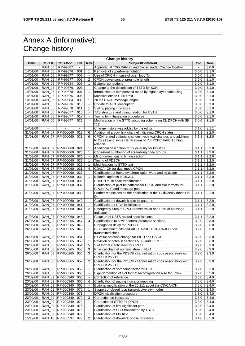
ETSI
ETSI TS 125 211 V8.7.0 (2010-10)553GPP TS 25.211 version 8.7.0 Release 8
Annex A (informative): Change history
Change history Date TSG # TSG Doc. CR Rev Subject/Comment Old New
RAN_05 RP-99587 - Approved at TSG RAN #5 and placed under Change Control - 3.0.0 14/01/00 RAN_06 RP-99676 001 1 Removal of superframe notation 3.0.0 3.1.0 14/01/00 RAN_06 RP-99677 002 - Use of CPICH in case of open loop Tx 3.0.0 3.1.0 14/01/00 RAN_06 RP-99677 003 2 CPCH power control preamble length 3.0.0 3.1.0 14/01/00 RAN_06 RP-99684 005 1 Editorial corrections 3.0.0 3.1.0 14/01/00 RAN_06 RP-99676 006 - Change to the description of TSTD for SCH 3.0.0 3.1.0 14/01/00 RAN_06 RP-99678 007 1 Introduction of compressed mode by higher layer scheduling 3.0.0 3.1.0 14/01/00 RAN_06 RP-99676 008 1 Modifications to STTD text 3.0.0 3.1.0 14/01/00 RAN_06 RP-99684 009 1 20 ms RACH message length 3.0.0 3.1.0 14/01/00 RAN_06 RP-99676 010 - Update to AICH description 3.0.0 3.1.0 14/01/00 RAN_06 RP-99678 011 1 Sliding paging indicators 3.0.0 3.1.0 14/01/00 RAN_06 RP-99677 016 - TAB structure and timing relation for USTS 3.0.0 3.1.0 14/01/00 RAN_06 RP-99677 017 - Timing for initialisation procedures 3.0.0 3.1.0 14/01/00 RAN_06 RP-99677 022 - Modification of the STTD encoding scheme on DL DPCH with SF
512 3.0.0 3.1.0
14/01/00 - - - Change history was added by the editor 3.1.0 3.1.1 31/03/00 RAN_07 RP-000060 013 6 Addition of a downlink channel indicating CPCH status 3.1.1 3.2.0 31/03/00 RAN_07 RP-000060 023 6 CPCH-related editorial changes, technical changes and additions
to 25.211 and some clarifications to 7.4 PCPCH/AICH timing relation.
3.1.1 3.2.0
31/03/00 RAN_07 RP-000060 024 1 Additional description of TX diversity for PDSCH 3.1.1 3.2.0 31/03/00 RAN_07 RP-000060 025 1 Consistent numbering of scrambling code groups 3.1.1 3.2.0 31/03/00 RAN_07 RP-000060 026 - Minor corrections to timing section 3.1.1 3.2.0 31/03/00 RAN_07 RP-000060 028 1 Timing of PDSCH 3.1.1 3.2.0 31/03/00 RAN_07 RP-000060 029 1 Modifications to STTD text 3.1.1 3.2.0 31/03/00 RAN_07 RP-000060 031 4 CD/CA-ICH for dual mode CPCH 3.1.1 3.2.0 31/03/00 RAN_07 RP-000060 033 - Clarification of frame synchronization word and its usage 3.1.1 3.2.0 31/03/00 RAN_07 RP-000060 034 1 Editorial updates to 25.211 3.1.1 3.2.0 31/03/00 RAN_07 RP-000060 036 - PDSCH multi-code transmission 3.1.1 3.2.0 31/03/00 RAN_07 RP-000060 037 - Clarification of pilot bit patterns for CPCH and slot formats for
CPCH PC-P and message part 3.1.1 3.2.0
31/03/00 RAN_07 RP-000060 039 - Further restrictions on the application of the Tx diversity modes in DL
3.1.1 3.2.0
31/03/00 RAN_07 RP-000060 040 - Clarification of downlink pilot bit patterns 3.1.1 3.2.0 31/03/00 RAN_07 RP-000060 041 - Clarification of DCH initialisation 3.1.1 3.2.0 31/03/00 RAN_07 RP-000060 044 2 Emergency Stop of CPCH transmission and Start of Message
Indicator 3.1.1 3.2.0
31/03/00 RAN_07 RP-000060 046 - Clean up of USTS related specifications 3.1.1 3.2.0 26/06/00 RAN_08 RP-000265 047 4 Clarifications to power control preamble sections 3.2.0 3.3.0 26/06/00 RAN_08 RP-000265 048 - Propagation delay for PCPCH 3.2.0 3.3.0 26/06/00 RAN_08 RP-000265 049 1 PICH undefined bits and AICH, AP-ICH, CD/CA-ICH non-
transmitted chips 3.2.0 3.3.0
26/06/00 RAN_08 RP-000265 051 1 Bit value notation change for PICH and CSICH 3.2.0 3.3.0 26/06/00 RAN_08 RP-000265 053 1 Revision of notes in sections 5.3.2 and 5.3.2.1 3.2.0 3.3.0 26/06/00 RAN_08 RP-000265 054 5 Slot format clarification for CPCH 3.2.0 3.3.0 26/06/00 RAN_08 RP-000265 055 3 Physical channel nomenclature in FDD 3.2.0 3.3.0 26/06/00 RAN_08 RP-000265 056 3 Clarification for the PDSCH channelisation code association with
DPCH in 25.211 3.2.0 3.3.0
26/06/00 RAN_08 RP-000265 057 2 Clarification for the PDSCH channelisation code association with DPCH in 25.211
3.2.0 3.3.0
26/06/00 RAN_08 RP-000265 058 - Clarification of spreading factor for AICH 3.2.0 3.3.0 26/06/00 RAN_08 RP-000265 060 - Explicit mention of slot format reconfiguration also for uplink 3.2.0 3.3.0 23/09/00 RAN_09 RP-000340 065 - Correction of reference 3.3.0 3.4.0 23/09/00 RAN_09 RP-000340 066 4 Clarification of paging indicator mapping 3.3.0 3.4.0 23/09/00 RAN_09 RP-000340 068 - Editorial modification of the 25.211 about the CD/CA-ICH 3.3.0 3.4.0 23/09/00 RAN_09 RP-000340 070 1 Support of closed loop transmit diversity modes 3.3.0 3.4.0 23/09/00 RAN_09 RP-000340 071 - DPCH initialisation procedure 3.3.0 3.4.0 23/09/00 RAN_09 RP-000340 072 3 Correction on indicators 3.3.0 3.4.0 23/09/00 RAN_09 RP-000340 074 - Correction of STTD for DPCH 3.3.0 3.4.0 23/09/00 RAN_09 RP-000340 075 - Clarification of first significant path 3.3.0 3.4.0 23/09/00 RAN_09 RP-000340 076 - Clarification of SCH transmitted by TSTD 3.3.0 3.4.0 23/09/00 RAN_09 RP-000340 077 1 Clarification of FBI field 3.3.0 3.4.0 15/12/00 RAN_10 RP-000537 079 2 Clarification of downlink phase reference 3.4.0 3.5.0
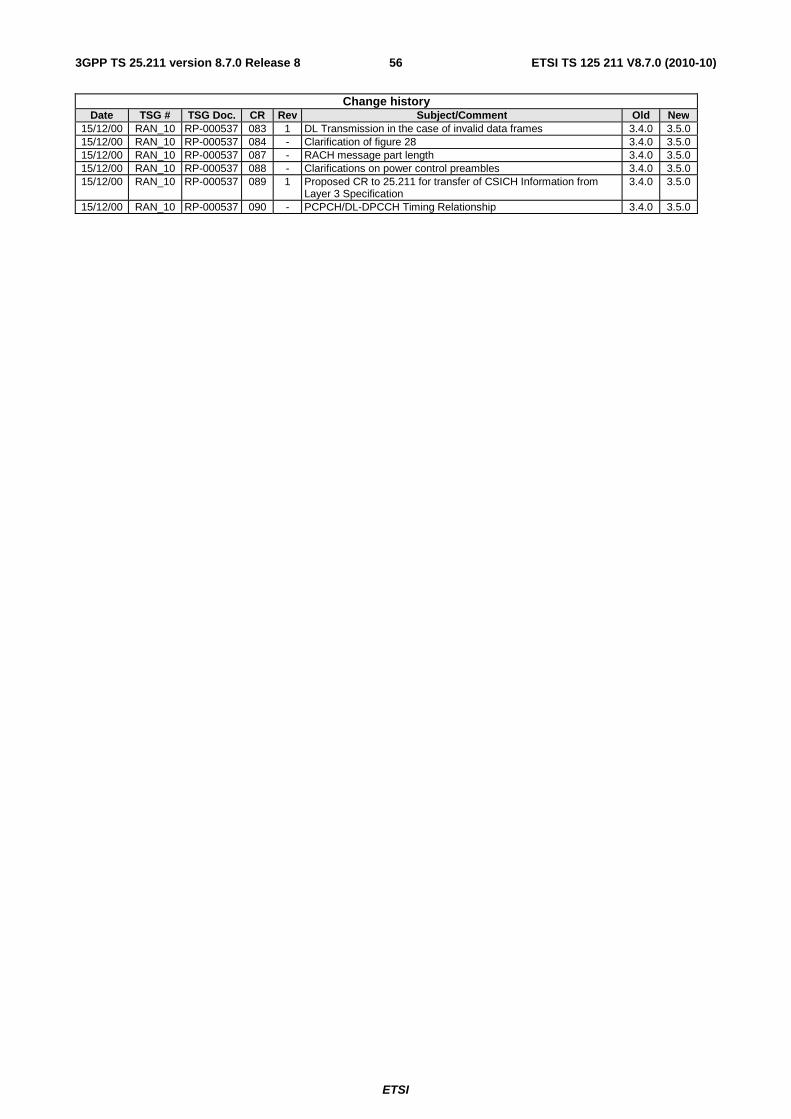
ETSI
ETSI TS 125 211 V8.7.0 (2010-10)563GPP TS 25.211 version 8.7.0 Release 8
Change history Date TSG # TSG Doc. CR Rev Subject/Comment Old New
15/12/00 RAN_10 RP-000537 083 1 DL Transmission in the case of invalid data frames 3.4.0 3.5.0 15/12/00 RAN_10 RP-000537 084 - Clarification of figure 28 3.4.0 3.5.0 15/12/00 RAN_10 RP-000537 087 - RACH message part length 3.4.0 3.5.0 15/12/00 RAN_10 RP-000537 088 - Clarifications on power control preambles 3.4.0 3.5.0 15/12/00 RAN_10 RP-000537 089 1 Proposed CR to 25.211 for transfer of CSICH Information from
Layer 3 Specification 3.4.0 3.5.0
15/12/00 RAN_10 RP-000537 090 - PCPCH/DL-DPCCH Timing Relationship 3.4.0 3.5.0
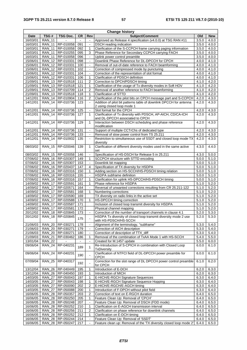
ETSI
ETSI TS 125 211 V8.7.0 (2010-10)573GPP TS 25.211 version 8.7.0 Release 8
Change history Date TSG # TSG Doc. CR Rev Subject/Comment Old New
16/03/01 RAN_11 - - - Approved as Release 4 specification (v4.0.0) at TSG RAN #11 3.5.0 4.0.0 16/03/01 RAN_11 RP-010058 091 - DSCH reading indication 3.5.0 4.0.0 16/03/01 RAN_11 RP-010058 092 1 Clarification of the S-CCPCH frame carrying paging information 3.5.0 4.0.0 16/03/01 RAN_11 RP-010255 095 3 Phase Reference for Secondary CCPCH carrying FACH 3.5.0 4.0.0 16/03/01 RAN_11 RP-010058 096 - Uplink power control preamble 3.5.0 4.0.0 15/06/01 RAN_12 RP-010331 098 - Downlink Phase Reference for DL-DPCCH for CPCH 4.0.0 4.1.0 15/06/01 RAN_12 RP-010331 100 - Removal of out-of-date reference to FACH beamforming 4.0.0 4.1.0 15/06/01 RAN_12 RP-010331 102 - Correction of compressed mode by puncturing 4.0.0 4.1.0 15/06/01 RAN_12 RP-010331 104 - Correction of the representation of slot format 4.0.0 4.1.0 15/06/01 RAN_12 RP-010331 106 1 Clarification of PDSCH definition 4.0.0 4.1.0 21/09/01 RAN_13 RP-010518 111 2 Correction to DPCH/PDSCH timing 4.1.0 4.2.0 21/09/01 RAN_13 RP-010518 121 1 Clarification of the usage of Tx diversity modes in Soft HOV 4.1.0 4.2.0 21/09/01 RAN_13 RP-010709 114 2 Removal of another reference to FACH beamforming 4.1.0 4.2.0 21/09/01 RAN_13 RP-010518 118 1 Clarification of STTD 4.1.0 4.2.0 14/12/01 RAN_14 RP-010904 116 2 Clarification of the pilot bits on CPCH message part and S-CCPCH 4.2.0 4.3.0 14/12/01 RAN_14 RP-010736 123 - Addition of pilot bit patterns table of downlink DPCCH for antenna
2 using closed loop mode 1 4.2.0 4.3.0
14/12/01 RAN_14 RP-010736 125 - Slot format for the CPCH 4.2.0 4.3.0 14/12/01 RAN_14 RP-010736 127 1 Clarification of Tx diversity with PDSCH, AP-AICH, CD/CA-ICH
and DL-DPCCH associated to CPCH 4.2.0 4.3.0
14/12/01 RAN_14 RP-010736 129 1 Interaction between DSCH scheduling and phase reference modification
4.2.0 4.3.0
14/12/01 RAN_14 RP-010736 131 - Support of multiple CCTrChs of dedicated type 4.2.0 4.3.0 14/12/01 RAN_14 RP-010736 133 - Removal of slow power control from TS 25.211 4.2.0 4.3.0 14/12/01 RAN_14 RP-010932 135 - Restriction to simultaneous use of SSDT and closed loop mode TX
diversity 4.2.0 4.3.0
08/03/02 RAN_15 RP-020046 139 1 Clarification of different diversity modes used in the same active set
4.3.0 4.4.0
08/03/02 RAN_15 RP-020058 146 - Specification of HS-DSCH for Release 5 in 25.211 4.3.0 5.0.0 07/06/02 RAN_16 RP-020307 149 1 SCCPCH structure with STTD encoding 5.0.0 5.1.0 07/06/02 RAN_16 RP-020307 153 - Downlink bit mapping 5.0.0 5.1.0 07/06/02 RAN_16 RP-020437 147 4 Specification of TX diversity for HSDPA 5.0.0 5.1.0 07/06/02 RAN_16 RP-020316 150 1 Adding section on HS-SCCH/HS-PDSCH timing relation 5.0.0 5.1.0 07/06/02 RAN_16 RP-020316 155 - HSDPA subframe definition 5.0.0 5.1.0 07/06/02 RAN_16 RP-020316 157 1 Clarification for uplink HS-DPCCH/HS-PDSCH timing 5.0.0 5.1.0 14/09/02 RAN_17 RP-020591 161 1 Phase reference for HSDPA 5.1.0 5.2.0 14/09/02 RAN_17 RP-020571 164 - Reversal of unwanted corrections resulting from CR 25.211-122 5.1.0 5.2.0 14/09/02 RAN_17 RP-020581 168 1 Numbering corrections 5.1.0 5.2.0 14/09/02 RAN_17 RP-020590 169 TX diversity on radio links in the active set 5.1.0 5.2.0 14/09/02 RAN_17 RP-020588 170 1 HS-DPCCH timing correction 5.1.0 5.2.0 14/09/02 RAN_17 RP-020587 171 Inclusion of closed loop transmit diversity for HSDPA 5.1.0 5.2.0 14/09/02 RAN_17 RP-020581 172 Physical channel mapping 5.1.0 5.2.0 20/12/02 RAN_18 RP-020845 173 - Correction of the number of transport channels in clause 4.1 5.2.0 5.3.0 20/12/02 RAN_18 RP-020845 175 - HSDPA Tx diversity of closed loop transmit diversity mode 2 use
with HS-PDSCH/HS-SCCH 5.2.0 5.3.0
21/06/03 RAN_20 RP-030271 178 - Alignment of the terminology, "subframe" 5.3.0 5.4.0 21/06/03 RAN_20 RP-030271 179 - Correction of AICH description 5.3.0 5.4.0 21/06/03 RAN_20 RP-030271 180 - Correction of description of TTX_diff 5.3.0 5.4.0 21/09/03 RAN_21 RP-030462 186 1 Removal of the combination of TxAA Mode 1 with HS-SCCH 5.4.0 5.5.0 13/01/04 RAN_22 - - - Created for M.1457 update 5.5.0 6.0.0 09/06/04 RAN_24 RP-040231 189 1 Re-Introduction of S-CPICH in combination with Closed Loop
TxDiversity 6.0.0 6.1.0
09/06/04 RAN_24 RP-040231 190 - Clarification of NTFCI field of DL-DPCCH power preamble for CPCH
6.0.0 6.1.0
07/09/04 RAN_25 RP-040317 192 -
Correction for the slot range of DL DPCCH power control preamble for CPCH
6.1.0 6.2.0
13/12/04 RAN_26 RP-040449 195 1 Introduction of E-DCH 6.2.0 6.3.0 13/12/04 RAN_26 RP-040450 193 1 Introduction of MICH 6.2.0 6.3.0 14/03/05 RAN_27 RP-050043 197 1 E-HICH/E-RGCH Signature Sequences 6.3.0 6.4.0 14/03/05 RAN_27 RP-050043 198 1 E-HICH/E-RGCH Signature Sequence Hopping 6.3.0 6.4.0 14/03/05 RAN_27 RP-050090 202 2 E-HICH/E-RGCH/E-AGCH timing 6.3.0 6.4.0 14/03/05 RAN_27 RP-050088 200 1 Introduction of F-DPCH without pilot field 6.3.0 6.4.0 16/06/05 RAN_28 RP-050357 203 2 Correction of text on E-RGCH duration 6.4.0 6.5.0 16/06/05 RAN_28 RP-050250 205 1 Feature Clean Up: Removal of 'CPCH' 6.4.0 6.5.0 16/06/05 RAN_28 RP-050248 207 - Feature Clean Up: Removal of DSCH (FDD mode) 6.4.0 6.5.0 16/06/05 RAN_28 RP-050252 210 1 Clarification on E-AGCH transmission interval 6.4.0 6.5.0 16/06/05 RAN_28 RP-050256 211 2 Clarification on phase reference for downlink channels 6.4.0 6.5.0 16/06/05 RAN_28 RP-050252 212 1 Clarification on E-DCH timing 6.4.0 6.5.0 16/06/05 RAN_28 RP-050244 214 - Feature Clean Up: Removal of 'SSDT' 6.4.0 6.5.0 16/06/05 RAN_28 RP-050247 217 - Feature clean up: Removal of the 'TX diversity closed loop mode 2' 6.4.0 6.5.0
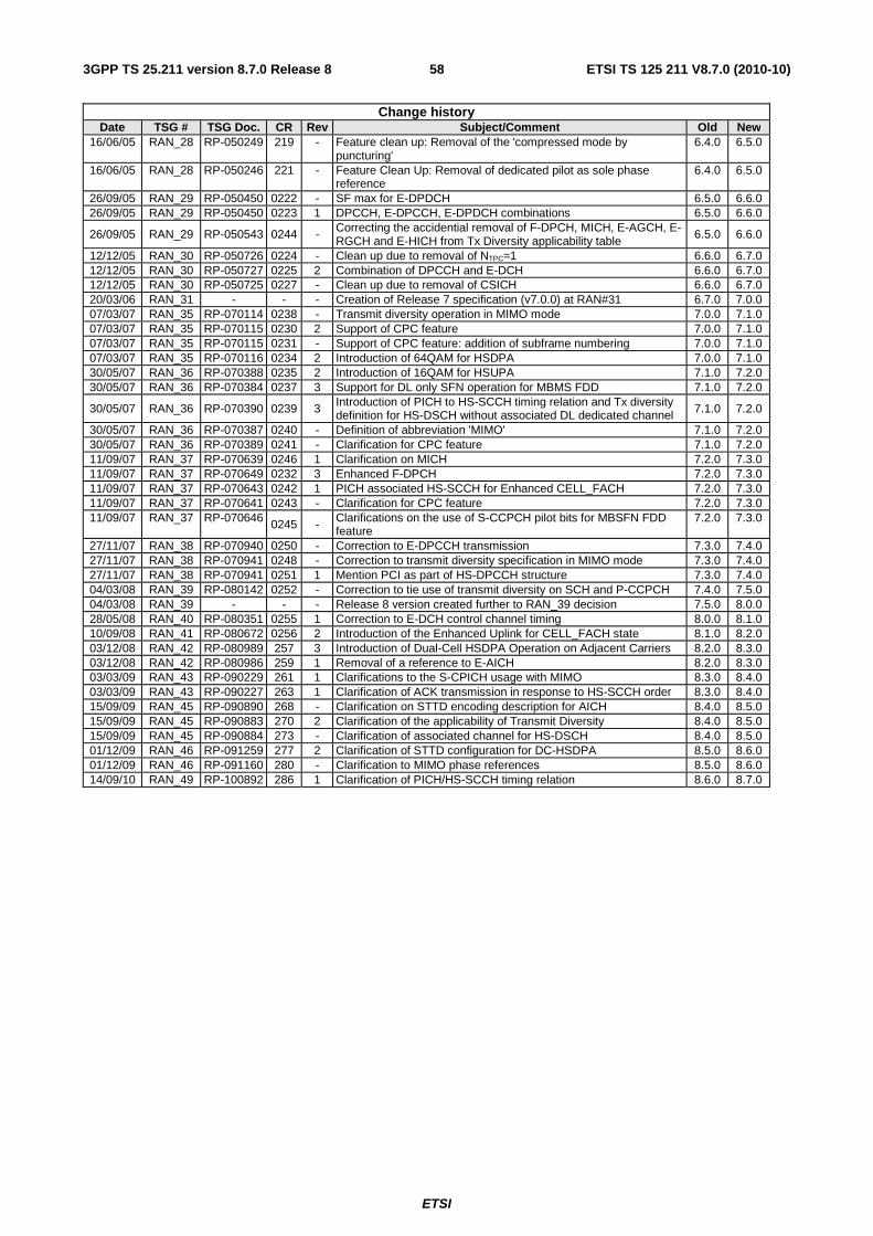
ETSI
ETSI TS 125 211 V8.7.0 (2010-10)583GPP TS 25.211 version 8.7.0 Release 8
Change history Date TSG # TSG Doc. CR Rev Subject/Comment Old New
16/06/05 RAN_28 RP-050249 219 - Feature clean up: Removal of the 'compressed mode by puncturing'
6.4.0 6.5.0
16/06/05 RAN_28 RP-050246 221 - Feature Clean Up: Removal of dedicated pilot as sole phase reference
6.4.0 6.5.0
26/09/05 RAN_29 RP-050450 0222 - SF max for E-DPDCH 6.5.0 6.6.0 26/09/05 RAN_29 RP-050450 0223 1 DPCCH, E-DPCCH, E-DPDCH combinations 6.5.0 6.6.0
26/09/05 RAN_29 RP-050543 0244 - Correcting the accidential removal of F-DPCH, MICH, E-AGCH, E-RGCH and E-HICH from Tx Diversity applicability table
6.5.0 6.6.0
12/12/05 RAN_30 RP-050726 0224 - Clean up due to removal of NTPC=1 6.6.0 6.7.0 12/12/05 RAN_30 RP-050727 0225 2 Combination of DPCCH and E-DCH 6.6.0 6.7.0 12/12/05 RAN_30 RP-050725 0227 - Clean up due to removal of CSICH 6.6.0 6.7.0 20/03/06 RAN_31 - - - Creation of Release 7 specification (v7.0.0) at RAN#31 6.7.0 7.0.0 07/03/07 RAN_35 RP-070114 0238 - Transmit diversity operation in MIMO mode 7.0.0 7.1.0 07/03/07 RAN_35 RP-070115 0230 2 Support of CPC feature 7.0.0 7.1.0 07/03/07 RAN_35 RP-070115 0231 - Support of CPC feature: addition of subframe numbering 7.0.0 7.1.0 07/03/07 RAN_35 RP-070116 0234 2 Introduction of 64QAM for HSDPA 7.0.0 7.1.0 30/05/07 RAN_36 RP-070388 0235 2 Introduction of 16QAM for HSUPA 7.1.0 7.2.0 30/05/07 RAN_36 RP-070384 0237 3 Support for DL only SFN operation for MBMS FDD 7.1.0 7.2.0
30/05/07 RAN_36 RP-070390 0239 3 Introduction of PICH to HS-SCCH timing relation and Tx diversity definition for HS-DSCH without associated DL dedicated channel 7.1.0 7.2.0
30/05/07 RAN_36 RP-070387 0240 - Definition of abbreviation 'MIMO' 7.1.0 7.2.0 30/05/07 RAN_36 RP-070389 0241 - Clarification for CPC feature 7.1.0 7.2.0 11/09/07 RAN_37 RP-070639 0246 1 Clarification on MICH 7.2.0 7.3.0 11/09/07 RAN_37 RP-070649 0232 3 Enhanced F-DPCH 7.2.0 7.3.0 11/09/07 RAN_37 RP-070643 0242 1 PICH associated HS-SCCH for Enhanced CELL_FACH 7.2.0 7.3.0 11/09/07 RAN_37 RP-070641 0243 - Clarification for CPC feature 7.2.0 7.3.0 11/09/07 RAN_37 RP-070646 0245 - Clarifications on the use of S-CCPCH pilot bits for MBSFN FDD
feature 7.2.0 7.3.0
27/11/07 RAN_38 RP-070940 0250 - Correction to E-DPCCH transmission 7.3.0 7.4.0 27/11/07 RAN_38 RP-070941 0248 - Correction to transmit diversity specification in MIMO mode 7.3.0 7.4.0 27/11/07 RAN_38 RP-070941 0251 1 Mention PCI as part of HS-DPCCH structure 7.3.0 7.4.0 04/03/08 RAN_39 RP-080142 0252 - Correction to tie use of transmit diversity on SCH and P-CCPCH 7.4.0 7.5.0 04/03/08 RAN_39 - - - Release 8 version created further to RAN_39 decision 7.5.0 8.0.0 28/05/08 RAN_40 RP-080351 0255 1 Correction to E-DCH control channel timing 8.0.0 8.1.0 10/09/08 RAN_41 RP-080672 0256 2 Introduction of the Enhanced Uplink for CELL_FACH state 8.1.0 8.2.0 03/12/08 RAN_42 RP-080989 257 3 Introduction of Dual-Cell HSDPA Operation on Adjacent Carriers 8.2.0 8.3.0 03/12/08 RAN_42 RP-080986 259 1 Removal of a reference to E-AICH 8.2.0 8.3.0 03/03/09 RAN_43 RP-090229 261 1 Clarifications to the S-CPICH usage with MIMO 8.3.0 8.4.0 03/03/09 RAN_43 RP-090227 263 1 Clarification of ACK transmission in response to HS-SCCH order 8.3.0 8.4.0 15/09/09 RAN_45 RP-090890 268 - Clarification on STTD encoding description for AICH 8.4.0 8.5.0 15/09/09 RAN_45 RP-090883 270 2 Clarification of the applicability of Transmit Diversity 8.4.0 8.5.0 15/09/09 RAN_45 RP-090884 273 - Clarification of associated channel for HS-DSCH 8.4.0 8.5.0 01/12/09 RAN_46 RP-091259 277 2 Clarification of STTD configuration for DC-HSDPA 8.5.0 8.6.0 01/12/09 RAN_46 RP-091160 280 - Clarification to MIMO phase references 8.5.0 8.6.0 14/09/10 RAN_49 RP-100892 286 1 Clarification of PICH/HS-SCCH timing relation 8.6.0 8.7.0
ETSI
ETSI TS 125 211 V8.7.0 (2010-10)593GPP TS 25.211 version 8.7.0 Release 8
History
Document history
V8.1.0 October 2008 Publication
V8.2.0 October 2008 Publication
V8.3.0 January 2009 Publication
V8.4.0 March 2009 Publication
V8.5.0 September 2009 Publication
V8.6.0 January 2010 Publication
V8.7.0 October 2010 Publication


![[9] 5.3.3.1 SPO Kajian Ulang Uraian Tugas.pdf](https://img.dokumen.tips/doc/110x75/577c7c351a28abe05499bec9/9-5331-spo-kajian-ulang-uraian-tugaspdf.jpg)