Embed Size (px)
Citation preview
ETSI TS 101 724 V7.5.0 (2001-04)Technical Specification
Digital cellular telecommunications system (Phase 2+);Location Services (LCS);
(Functional description) - Stage 2(3GPP TS 03.71 version 7.5.0 Release 1998)
GLOBAL SYSTEM FORMOBILE COMMUNICATIONS
R
1
ETSI
ETSI TS 101 724 V7.5.0 (2001-04)3GPP TS 03.71 version 7.5.0 Release 1998
ReferenceRTS/TSGS-020371Q7R4
KeywordsGSM
ETSI
650 Route des LuciolesF-06921 Sophia Antipolis Cedex - FRANCE
Tel.: +33 4 92 94 42 00 Fax: +33 4 93 65 47 16
Siret N° 348 623 562 00017 - NAF 742 CAssociation à but non lucratif enregistrée à laSous-Préfecture de Grasse (06) N° 7803/88
Important notice
Individual copies of the present document can be downloaded from:http://www.etsi.org
The present document may be made available in more than one electronic version or in print. In any case of existing orperceived difference in contents between such versions, the reference version is the Portable Document Format (PDF).
In case of dispute, the reference shall be the printing on ETSI printers of the PDF version kept on a specific network drivewithin ETSI Secretariat.
Users of the present document should be aware that the document may be subject to revision or change of status.Information on the current status of this and other ETSI documents is available at http://www.etsi.org/tb/status/
If you find errors in the present document, send your comment to:[email protected]
Copyright Notification
No part may be reproduced except as authorized by written permission.The copyright and the foregoing restriction extend to reproduction in all media.
© European Telecommunications Standards Institute 2001.
All rights reserved.
2
ETSI
ETSI TS 101 724 V7.5.0 (2001-04)3GPP TS 03.71 version 7.5.0 Release 1998
Intellectual Property RightsIPRs essential or potentially essential to the present document may have been declared to ETSI. The informationpertaining to these essential IPRs, if any, is publicly available for ETSI members and non-members, and can be foundin ETSI SR 000 314: "Intellectual Property Rights (IPRs); Essential, or potentially Essential, IPRs notified to ETSI inrespect of ETSI standards", which is available from the ETSI Secretariat. Latest updates are available on the ETSI Webserver (http://www.etsi.org/ipr).
Pursuant to the ETSI IPR Policy, no investigation, including IPR searches, has been carried out by ETSI. No guaranteecan be given as to the existence of other IPRs not referenced in ETSI SR 000 314 (or the updates on the ETSI Webserver) which are, or may be, or may become, essential to the present document.
ForewordThis Technical Specification (TS) has been produced by the ETSI 3rd Generation Partnership Project (3GPP).
The present document may refer to technical specifications or reports using their 3GPP identities, UMTS identities orGSM identities. These should be interpreted as being references to the corresponding ETSI deliverables.
The cross reference between GSM, UMTS, 3GPP and ETSI identities can be found under www.etsi.org/key .

ETSI
ETSI TS 101 724 V7.5.0 (2001-04)33GPP TS 03.71 version 7.5.0 Release 1998
Contents
Foreword............................................................................................................................................................ 8
1 Scope ....................................................................................................................................................... 9
2 References ............................................................................................................................................... 9
3 Definitions, abbreviations and symbols................................................................................................. 10 3.1 Definitions..............................................................................................................................................................10 3.2 Abbreviations .........................................................................................................................................................11 3.3 Symbols..................................................................................................................................................................12
4 Main concepts........................................................................................................................................ 12 4.1 Assumptions...........................................................................................................................................................12 4.2 Timing Advance (TA)............................................................................................................................................13 4.3 Time of Arrival (TOA) positioning mechanism.....................................................................................................13 4.4 Enhanced Observed Time Difference (E-OTD) positioning mechanism...............................................................13 4.5 Global Positioning System (GPS) positioning mechanism ....................................................................................13
5 General LCS architecture ...................................................................................................................... 13 5.1 LCS access interfaces and reference points............................................................................................................13 5.2 LCS Functional diagram ........................................................................................................................................15 5.3 LCS CLIENT .........................................................................................................................................................15 5.3.1 LCS Component ...............................................................................................................................................16 5.3.1.1 Location Client Function (LCF) .......................................................................................................................16 5.4 LCS Server .............................................................................................................................................................16 5.4.1 Client handling component...............................................................................................................................16 5.4.1.1 Location Client Control Function (LCCF) .......................................................................................................16 5.4.1.2 Location Client Authorization Function (LCAF) .............................................................................................16 5.4.1.2.1 Access Subfunction.....................................................................................................................................16 5.4.1.2.2 Subscription Subfunction............................................................................................................................16 5.4.2 System handling component.............................................................................................................................17 5.4.2.1 LMU Mobility Management Function (LMMF) ..............................................................................................17 5.4.2.2 Location System Control Function (LSCF)......................................................................................................17 5.4.2.3 Location System Billing Function (LSBF).......................................................................................................17 5.4.2.4 Location Client Coordinate Transformation Function (LCCTF)......................................................................17 5.4.2.5 Location System Operations Function (LSOF) ................................................................................................17 5.4.2.6 Location System Broadcast Function (LSBcF) ................................................................................................17 5.4.3 Subscriber Component .....................................................................................................................................18 5.4.3.1 Location Subscriber Authorization Function (LSAF) ......................................................................................18 5.4.3.2 Location Subscriber Privacy Function (LSPF).................................................................................................18 5.4.4 Positioning component .....................................................................................................................................18 5.4.4.1 Positioning Radio Coordination Function (PRCF) ...........................................................................................18 5.4.4.2 Positioning Radio Assistance Function (PRAF)...............................................................................................18 5.4.4.3 Positioning Calculation Function (PCF)...........................................................................................................18 5.4.4.4 Positioning Signal Measurement Function (PSMF) .........................................................................................18 5.5 Information Flows between Client and Server .......................................................................................................18 5.5.1 Location Service Request .................................................................................................................................18 5.5.2 Location Service Response...............................................................................................................................19 5.6 Logical architecture................................................................................................................................................19 5.6.1 BSS...................................................................................................................................................................20 5.6.2 LCS Client ........................................................................................................................................................20 5.6.3 GMLC ..............................................................................................................................................................20 5.6.4 SMLC ...............................................................................................................................................................20 5.6.5 MS ....................................................................................................................................................................20 5.6.6 LMU .................................................................................................................................................................21 5.6.7 MSC .................................................................................................................................................................21 5.6.8 HLR..................................................................................................................................................................21 5.6.9 gsmSCF ............................................................................................................................................................22 5.6.10 LMU and SMLC association............................................................................................................................22
ETSI
ETSI TS 101 724 V7.5.0 (2001-04)43GPP TS 03.71 version 7.5.0 Release 1998
5.6.11 SGSN................................................................................................................................................................22 5.7 Embedded Architecture..........................................................................................................................................22 5.8 Assignment of functions to general logical architecture ........................................................................................23
6 Signalling Protocols and Interfaces ....................................................................................................... 24 6.1 Generic Signalling Model for LCS ........................................................................................................................24 6.1.1 Protocol layering ..............................................................................................................................................24 6.1.2 Message Segmentation .....................................................................................................................................25 6.1.2.1 Intermediate Level Segmentation .....................................................................................................................25 6.1.2.2 Network Level Segmentation ...........................................................................................................................25 6.2 Signalling between an SMLC, MSC and BSC.......................................................................................................25 6.3 SMLC Signaling to a Target MS............................................................................................................................26 6.4 SMLC Signalling to a Type A LMU......................................................................................................................27 6.4.1 Signalling using an SDCCH .............................................................................................................................27 6.4.2 Signalling using a TCH ....................................................................................................................................28 6.5 SMLC signaling to a Type B LMU........................................................................................................................29 6.6 SMLC Signalling to a peer SMLC.........................................................................................................................30
7 General Network Location Procedures.................................................................................................. 31 7.1 State Description for the GMLC ............................................................................................................................31 7.1.1 GMLC States ....................................................................................................................................................31 7.1.1.1 NULL State ......................................................................................................................................................31 7.1.1.2 INTERROGATION State.................................................................................................................................31 7.1.1.3 LOCATION State.............................................................................................................................................31 7.1.2 State Functionality............................................................................................................................................32 7.1.2.1 State Transitions ...............................................................................................................................................32 7.1.2.2 INTERROGATION Timer Function................................................................................................................32 7.1.2.3 LOCATION Timer Function............................................................................................................................32 7.2 State Description for the VMSC ............................................................................................................................33 7.2.1 VMSC States ....................................................................................................................................................33 7.2.1.1 IDLE State ........................................................................................................................................................33 7.2.1.2 LOCATION State.............................................................................................................................................33 7.2.2 State Functionality............................................................................................................................................33 7.2.2.1 State Transitions ...............................................................................................................................................33 7.2.2.2 LOCATION Timer Function............................................................................................................................34 7.3 State Description for the BSC ................................................................................................................................34 7.3.1 BSC States ........................................................................................................................................................34 7.3.1.1 IDLE State ........................................................................................................................................................34 7.3.1.2 LOCATION State.............................................................................................................................................34 7.3.2 State Functionality............................................................................................................................................34 7.3.2.1 State Transitions ...............................................................................................................................................34 7.3.2.2 LOCATION Timer Function............................................................................................................................35 7.4 State Description for the SMLC.............................................................................................................................35 7.4.1 SMLC States.....................................................................................................................................................35 7.4.1.1 NULL State ......................................................................................................................................................35 7.4.1.2 LOCATION State.............................................................................................................................................35 7.4.2 State Functionality............................................................................................................................................36 7.4.2.1 State Transitions ...............................................................................................................................................36 7.4.2.2 LOCATION Timer Function............................................................................................................................36 7.5 Usage of SCCP Connections on the Ls and Lb interfaces .....................................................................................36 7.5.1 SCCP connection for positioning of a target MS .............................................................................................37 7.5.2 SCCP connection to access a type A LMU ......................................................................................................38 7.6 General Network Positioning Procedures ..............................................................................................................38 7.6.1 Mobile Terminating Location Request (MT-LR) .............................................................................................39 7.6.1.1 Location Preparation Procedure .......................................................................................................................39 7.6.1.2 Positioning Measurement Establishment Procedure.........................................................................................41 7.6.1.3 Location Calculation and Release Procedure ...................................................................................................41 7.6.2 MT-LR without HLR Query - applicable to North America Emergency Calls only........................................42 7.6.3 MT-LR for a previously obtained location estimate.........................................................................................43 7.6.3.1 Initial Location .................................................................................................................................................43 7.6.3.2 Current Location...............................................................................................................................................43 7.6.3.3 Last known Location ........................................................................................................................................43
ETSI
ETSI TS 101 724 V7.5.0 (2001-04)53GPP TS 03.71 version 7.5.0 Release 1998
7.6.3.4 Security and Privacy.........................................................................................................................................43 7.6.3.5 Failing to locate the target MS .........................................................................................................................43 7.6.3.5.1 Target MS is ’Not Reachable’......................................................................................................................43 7.6.3.5.2 Target MS is ’Detached’..............................................................................................................................44 7.6.3.5.3 Target MS is Reachable but Positioning Fails ............................................................................................44 7.6.3.5.4 Target MS is ’Purged’..................................................................................................................................44 7.6.4 Network Induced Location Request (NI-LR) ...................................................................................................45 7.6.4.1 Location Preparation Procedure .......................................................................................................................45 7.6.4.2 Positioning Measurement Establishment Procedure.........................................................................................46 7.6.4.3 Location Calculation and Release Procedure ...................................................................................................46 7.6.5 Network Induced Location Request (NI-LR) from a Serving BSC for a target MS in dedicated mode...........46 7.6.5.1 Location Preparation Procedure .......................................................................................................................47 7.6.5.2 Positioning Measurement Establishment Procedure.........................................................................................47 7.6.5.3 Location Calculation and Release Procedure ...................................................................................................47 7.6.6 Mobile Originating Location Request (MO-LR)..............................................................................................48 7.6.6.1 Location Preparation Procedure .......................................................................................................................49 7.6.6.2 Positioning Measurement Establishment Procedure.........................................................................................49 7.6.6.3 Location Calculation and Release Procedure ...................................................................................................50 7.7 Common Procedures to Support Positioning .........................................................................................................50 7.7.1 Information Transfer between an NSS based SMLC and a Target MS............................................................50 7.7.2 Information Transfer between a BSS based SMLC and a Target MS ..............................................................52 7.7.3 Information Transfer between an NSS based SMLC and a BSC .....................................................................53 7.7.4 Information Transfer between a BSS based SMLC and a BSC........................................................................54 7.8 Common Procedures to Support Access to an LMU..............................................................................................54 7.8.1 Information Transfer between an NSS based SMLC and a Type A LMU .......................................................55 7.8.1.1 Information Transfer using an SDCCH............................................................................................................55 7.8.1.2 Information Transfer using a TCH ...................................................................................................................56 7.8.2 Location Update Procedure between a BSS based SMLC and a Type A LMU ...............................................57 7.8.3 IMSI Detach Procedure between a BSS based SMLC and a Type A LMU .....................................................58 7.8.4 LCS Information Transfer between a BSS based SMLC and a Type A LMU .................................................59 7.8.4.1 Information Transfer using an SDCCH............................................................................................................59 7.8.4.2 Information Transfer using a TCH ...................................................................................................................60 7.8.5 Information Transfer between an NSS based SMLC and a Type B LMU .......................................................61 7.8.6 Information Transfer between a BSS based SMLC and a Type B LMU..........................................................62 7.9 Common Control Procedures for LMUs ................................................................................................................62 7.9.1 Reset Procedure ................................................................................................................................................63 7.9.2 Status Query Procedure ....................................................................................................................................63 7.9.3 Status Update Procedure...................................................................................................................................63 7.10 Common Procedures supporting Interaction between Peer SMLCs.................................................................64 7.10.1 Information Transfer between Peer SMLCs.....................................................................................................64 7.11 Exception Procedures .......................................................................................................................................65 7.11.1 Procedures in the SMLC...................................................................................................................................65 7.11.2 Procedures in the VMSC ..................................................................................................................................66 7.11.3 Procedures in an LMU......................................................................................................................................66 7.11.4 Procedures in the BSC......................................................................................................................................67 7.11.4.1 General Procedures .....................................................................................................................................67 7.11.4.2 Rejection of an SMLC Positioning Request ...............................................................................................67 7.11.4.3 Interaction with Inter-BSC or Inter-MSC Handover...................................................................................67 7.11.4.4 Interaction with Intra-BSC Handover and other RR Management Procedures...........................................67 7.11.4.5 Priority of Handover and Other RR Management Procedures....................................................................67 7.11.4.6 Interaction with Segmentation ....................................................................................................................68 7.11.4.7 Overload......................................................................................................................................................68 7.11.5 Procedures in the Target MS ............................................................................................................................68 7.11.6 Further Procedures for Handover .....................................................................................................................68 7.11.6.1 MSC procedure for Inter-MSC Handover...................................................................................................68 7.11.6.2 Handling of an ongoing handover while a request for positioning arrives at MSC/VLR ...........................68 7.12 Privacy..............................................................................................................................................................69 7.12.1 Privacy Override Indicator (POI) .....................................................................................................................69 7.12.2 Privacy Procedures ...........................................................................................................................................69 7.12.3 MS Privacy Options .........................................................................................................................................69 7.13 Mobile Originating Location ............................................................................................................................71 7.14 CM Procedures .................................................................................................................................................71
ETSI
ETSI TS 101 724 V7.5.0 (2001-04)63GPP TS 03.71 version 7.5.0 Release 1998
7.14.1 Location request for a mobile in idle-mode......................................................................................................71 7.14.2 Location request for a mobile in dedicated-mode ............................................................................................72 7.15 Radio Interface Timing Procedures ..................................................................................................................72 7.15.1 LMU Functions ................................................................................................................................................72 7.15.2 SMLC Functions ..............................................................................................................................................72 7.15.3 LMU-SMLC Interactions .................................................................................................................................72
8 TA based Positioning ............................................................................................................................ 73 8.1 Definition of TA states...........................................................................................................................................73 8.1.1 MS in IDLE State .............................................................................................................................................73 8.1.2 MS in DEDICATED State ...............................................................................................................................73 8.2 TA Positioning Procedure for an NSS based SMLC..............................................................................................74 8.3 TA Positioning Procedure for a BSS based SMLC................................................................................................74 8.4 Unsuccessful TA positioning procedure in BSC....................................................................................................75
9 TOA based positioning.......................................................................................................................... 76 9.1 TOA procedures .....................................................................................................................................................76 9.1.1 Successful TOA Positioning Procedure for NSS based SMLC........................................................................76 9.1.2 Successful TOA Positioning Procedure for BSS based SMLC ........................................................................78 9.1.3 Successful TOA positioning procedure in BSC ...............................................................................................79
10 E-OTD and GPS Positioning Procedures .............................................................................................. 80 10.1 General Procedures...........................................................................................................................................80 10.2 Positioning for BSS based SMLC ....................................................................................................................80 10.3 Positioning for NSS based SMLC ....................................................................................................................81 10.4 Assistance Data Delivery from BSS based SMLC...........................................................................................82 10.5 Assistance Data Delivery from NSS based SMLC...........................................................................................82 10.6 Error Handling for E-OTD and GPS ................................................................................................................83 10.6.1 NSS based SMLC.............................................................................................................................................84 10.6.2 BSS based SMLC.............................................................................................................................................85 10.7 Broadcast of ASSISTANCE DATA.................................................................................................................85 10.7.1 Point-To-Multipoint Assistance Data Broadcast Flow.....................................................................................86 10.7.2 Ciphering ..........................................................................................................................................................87 10.7.3 Algorithm .........................................................................................................................................................87 10.7.4 Deciphering key control and delivery to MS....................................................................................................88
11 Position calculation functionality .......................................................................................................... 90 11.1 TA.....................................................................................................................................................................90 11.2 Time Of Arrival (TOA) Positioning mechanism..............................................................................................90 11.3 Enhanced Observed Time Difference (E-OTD) ...............................................................................................90 11.4 Global Positioning System (GPS) positioning mechanism ..............................................................................90
12 Information storage ............................................................................................................................... 91 12.1 HLR..................................................................................................................................................................91 12.2 VLR..................................................................................................................................................................93 12.3 GMLC ..............................................................................................................................................................93 12.4 SMLC ...............................................................................................................................................................94 12.5 Recovery and Restoration Procedures ..............................................................................................................96
ETSI
ETSI TS 101 724 V7.5.0 (2001-04)73GPP TS 03.71 version 7.5.0 Release 1998
13 Operational Aspects............................................................................................................................... 96
Annex A (Informative): Examples of MT-LR ..................................................................................... 98
A.1 PLMN Roles.......................................................................................................................................... 98
A.2 Non-Call Related MT-LR...................................................................................................................... 98
A.3 Call Related MT-LR.............................................................................................................................. 99
Annex B (Informative): Description of TOA..................................................................................... 101
Annex C (informative): Description of E-OTD................................................................................. 102
C.1 Basic Concepts .................................................................................................................................... 102
C.2 Position Calculation Types.................................................................................................................. 102
C.3 Implementation Issues ......................................................................................................................... 104
Annex D (informative): Description Of Assisted GPS...................................................................... 105
D.1 Assisted-GPS....................................................................................................................................... 107
D.2 MS-Assisted GPS................................................................................................................................ 108
D.3 MS-Based GPS.................................................................................................................................... 108
D.4 References ........................................................................................................................................... 108
Annex E (informative): Change History............................................................................................ 109
ETSI
ETSI TS 101 724 V7.5.0 (2001-04)83GPP TS 03.71 version 7.5.0 Release 1998
Foreword This Technical Specification (TS) has been produced by the 3rd Generation Partnership Project (3GPP).
The contents of the present document are subject to continuing work within the TSG and may change following formal TSG approval. Should the TSG modify the contents of the present document, it will be re-released by the TSG with an identifying change of release date and an increase in version number as follows:
Version x.y.z
where:
x the first digit:
1 presented to TSG for information;
2 presented to TSG for approval;
3 or greater indicates TSG approved document under change control.
y the second digit is incremented for all changes of substance, i.e. technical enhancements, corrections, updates, etc.
z the third digit is incremented when editorial only changes have been incorporated in the document.
ETSI
ETSI TS 101 724 V7.5.0 (2001-04)93GPP TS 03.71 version 7.5.0 Release 1998
1 Scope The present document defines the stage-2 service description for the LoCation Services (LCS) feature on GSM, which provides the mechanisms to support mobile location services of operators, which are not covered by standardized GSM services. CCITT I.130 [4] describes a three-stage method for characterization of telecommunication services, and CCITT Q.65 [5]defines stage 2 of the method.
The LCS feature is a network feature and not a supplementary service. This version of the stage 2 service description covers aspects of LCS e.g., the functional model, architecture, positioning methods, message flows etc.
2 References The following documents contain provisions which, through reference in this text, constitute provisions of the present document.
• References are either specific (identified by date of publication, edition number, version number, etc.) or non-specific.
• For a specific reference, subsequent revisions do not apply.
• For a non-specific reference, the latest version applies. In the case of a reference to a 3GPP document (including a GSM document), a non-specific reference implicitly refers to the latest version of that document in the same Release as the present document.
[1] GSM 01.04: "Digital cellular telecommunications system (Phase 2+); Abbreviations and acronyms".
[2] GSM 02.71: "Digital cellular telecommunications system (Phase 2+); Location Services (LCS); Service description; Stage 1".
[3] GSM 03.07: "Digital cellular telecommunications system (Phase 2+); Restoration Procedures".
[3a] GSM 03.32: “Universal Geographical Area Description (GAD)”
[4] GSM 03.41: "Digital cellular telecommunication system (Phase 2+); Technical realization of Short Message Service Cell Broadcast (SMSCB)".
[5] GSM 03.49: "Digital cellular telecommunication system (Phase 2+); Example protocol stacks for interconnecting Cell Broadcast Centre (CBC) and Mobile-services Switching Centre (MSC)".
[6] GSM 03.78: "Digital cellular telecommunications system (Phase 2+); Customized Application for Mobile network Enhanced Logic (CAMEL) Phase 3; Stage 3".
[6a] GSM 04.06: "Digital cellular telecommunications system (Phase 2+); Mobile Station - Base Station System (MS - BSS) interface Data Link (DL) layer specification".
[7] GSM 04.08: "Digital cellular telecommunications system (Phase 2+); Mobile radio interface layer 3 specification".
[8] GSM 04.31: "Digital cellular telecommunications system (Phase 2+); Location Services (LCS); Mobile Station (MS) – Serving Mobile Location Center (SMLC); Radio Resource LCS Protocol (RRLP)".
[9] GSM 04.71: "Digital cellular telecommunications system (Phase 2+); Mobile radio interface layer 3 Location Services (LCS) specification".
[10] GSM 08.08: "Digital cellular telecommunications system (Phase 2+); Mobile-services Switching Centre – Base Station System (MSC-BSS) interface; Layer 3 specification".
ETSI
ETSI TS 101 724 V7.5.0 (2001-04)103GPP TS 03.71 version 7.5.0 Release 1998
[11] GSM 08.31: "Digital cellular telecommunications system (Phase 2+); Location Services (LCS); Serving Mobile Location Center (SMLC) – Serving Mobile Location Center (SMLC); SMLC Peer Protocol (SMLCPP)".
[11a] GSM 08.58: "Digital cellular telecommunications system (Phase 2+); Base Station Controller - Base Transceiver Station (BSC - BTS) interface; Layer 3 specification".
[12] GSM 08.71: "Digital cellular telecommunications system (Phase 2+); Location Services (LCS); Serving Mobile Location Center – Base Station Subsystem (SMLC-BSS) interface Layer 3 specification".
[13] GSM 09.02: "Digital cellular telecommunications system (Phase 2+); Mobile Application Part (MAP) specification".
[14] GSM 09.31: "Digital cellular telecommunications system (Phase 2+); Location Services (LCS); Base Station System Application Part LCS Extension (BSSAP-LE)".
[15] CCITT Recommendations I.130: "General modelling methods – Method for the characterisation of telecommunication services supported by an ISDN and network capabilities of an ISDN".
[16] CCITT Recommendation Q.65: "Methodology – Stage 2 of the method for the characterization of services supported by an ISDN".
[17] TIA/EIA/IS-J-STD-036 – Enhanced Wireless 9-1-1 Phase II, August 2000.
3 Definitions, abbreviations and symbols
3.1 Definitions For the purposes of the present document the following terms and definitions apply.
Location Estimate: the geographic location of an MS and/or a valid ME, expressed in latitude and longitude data. . The Location Estimate shall be represented in a well-defined universal format. Translation from this universal format to another geographic location system may be supported, although the details are considered outside the scope of the primitive services.
Mobile Assisted positioning: any mobile centric positioning method (e.g. E-OTD, GPS) in which the MS provides position measurements to the network for computation of a location estimate by the network. The network may provide assistance data to the MS to enable position measurements and/or improve measurement performance.
Mobile Based positioning: any mobile centric positioning method (e.g. E-OTD, GPS) in which the MS performs both position measurements and computation of a location estimate and where assistance data useful or essential to one or both of these functions is provided to the MS by the network. Position methods where an MS performs measurements and location computation without network assistance data are not considered within this category.
Mobile Originating Location Request (MO-LR): any location request from a client MS to the LCS Server made over the GSM air interface. While an MO-LR could be used to request the location of another MS, its primary purpose is to obtain an estimate of the client MS's own location either for the client MS itself or for another LCS client designated by the MS.
Mobile Terminating Location Request (MT-LR): any location request from an LCS client where the client is treated as being external to the PLMN to which the location request is made.
Network Induced Location Request (NI-LR): any location request for a target MS from a client that can be considered to lie inside any of the PLMN entities currently serving the target MS. In this case, the LCS client is also within the LCS server. Examples of an NI-LR include a location request needed for supplementary services, for emergency call origination and by O&M in a visited PLMN.
North American Emergency Services Routing Digits (NA-ESRD): a telephone number in the North American Numbering Plan (NANP) that can be used to identify a North American emergency services provider and any associated LCS client. The ESRD shall also identify the base station , cell site or sector from which a North American emergency call originates.
ETSI
ETSI TS 101 724 V7.5.0 (2001-04)113GPP TS 03.71 version 7.5.0 Release 1998
North American Emergency Services Routing Key (NA-ESRK): a telephone number in the North American Numbering Plan (NANP) assigned to an emergency services call by a North American VPLMN for the duration of the call that can be used to identify (e.g. route to) both the emergency services provider and the switch in the VPLMN currently serving the emergency caller. During the lifetime of an emergency services call, the ESRK can also be used to identify the calling mobile subscriber.
3.2 Abbreviations Certain abbreviations used in the present document are also listed in GSM 01.04.
For the purposes of the present document, the following abbreviations apply:
ANM Answer Message (ISUP) BSSAP-LE BSSAP LCS Extension for Lb, Lp and Ls interfaces BSSLAP BSS LCS Assistance Protocol BSSMAP-LE BSSMAP LCS Extension CC SCCP Connection Confirm CR SCCP Connection Request CREF SCCP Connection Refused DT1 SCCP Data Form 1 message FEC Forward Error Correction GPRS General Packet Radio Service IAM Initial Address Message (ISUP) LIR Location Immediate Request LDR Location Deferred Request LCF Location Client Function LCCF Location Client Control Function LCAF Location Client Authorization Function LLP LMU LCS Protocol LMMF LMU Mobility Management Function LMU Location Measurement Unit LSCF Location System Control Function LSAF Location Subscriber Authorization Function LSPF Location Subscriber Privacy Function LSBcF Location System Broadcast Function LSBF Location System Billing Function LSOF Location System Operations Function LCCTF Location Client Coordinate Transformation Function MO-LR Mobile Originating Location Request MT-LR Mobile Terminating Location Request NI-LR Network Induced Location Request MLC Mobile Location Center PRAF Positioning Radio Assistance Function PRCF Positioning Radio Coordination Function PCF Positioning Calculation Function PSMF Positioning Signal Measurement Function RA Rate Adaptation REL Release (ISUP) RLC Release Complete (ISUP or SCCP) RLP Radio Link Protocol (GSM 04.22) RLSD SCCP Released message RRLP RR LCS Protocol to a target MS (defined in GSM 04.31) SGSN Serving GPRS Support Node SLPP Subscriber LCS Privacy Profile SMLCPP SMLC Peer Protocol (messages on Lp interface in GSM 08.31) TA Timing Advance (between an MS and its serving BTS) TOA Time of Arrival UDT SCCP Unitdata message

ETSI
ETSI TS 101 724 V7.5.0 (2001-04)123GPP TS 03.71 version 7.5.0 Release 1998
3.3 Symbols For the purposes of the present document, the following symbols apply:
Gb Interface between SGSN and BSS Gs Interface between MSC and SGSN Lb Interface between Serving MLC and BSC (BSC interface) Lc Interface between gateway MLC and gsmSCF (CAMEL interface) Le Interface between External User and MLC (external interface) Lh Interface between Gateway MLC and HLR (HLR interface) Lg Interface between Gateway MLC and VMSC (gateway MLC interface) Lp Interface between SMLC and peer SMLC (peer interface) Ls Interface between Serving MLC and VMSC (serving MLC interface) Um Air Interface to an LMU (measurement interface)
4 Main concepts LCS utilizes one or more positioning mechanisms in order to determine the location of a Mobile Station. Positioning a target MS involves two main steps: signal measurements and location estimate computation based on the measured signals.
Three positioning mechanisms are proposed for LCS: Uplink Time of Arrival (TOA), Enhanced Observed Time Difference (E-OTD), and Global Positioning System (GPS) assisted.
4.1 Assumptions - Support an SMLC that can be either BSS based or NSS based. While the SMLC is considered to be a separate
logical entity, it may still be physically part of an MSC or BSC.
- Standardize a similar open interface to the SMLC whether it is NSS or BSS based. This simplifies migration from an NSS to a BSS based location architecture and avoids two different types of SMLC.
- Support "Type A" LMUs accessed over the GSM air interface using the same signaling protocols for both BSS and NSS based SMLC interaction. A type A LMU supports the RR and MM signaling procedures defined in GSM 04.08. A type A LMU may have a subscription profile in the HLR and may support certain CM services – e.g. outgoing data calls for SW download and SMS for SIM card download.
- Support "Type B" LMUs accessed over the Abis interface. The LMU may be either free standing (support Abis signaling) or associated with a BTS – either integrated or connected by proprietary means. If free standing, a type B LMU could be identified using a pseudo cell ID.
- Employ the same application protocol defined in GSM 04.71 for all types of LMU.
- Use MTP, SCCP, BSSAP as the basis for all LCS signaling between the SMLC, BSC, MSC and (for GPRS) SGSN, since these are the only protocols that are all supported in a BSC, MSC and SGSN. Substitution of TCP/IP or FR could be used in 3G. An important consequence of this change is that TCAP and MAP are no longer needed for signaling to an SMLC (since retention of TCAP and MAP would only be feasible for an NSS based SMLC, thereby producing two distinct types of SMLC).
- Provide enough flexibility to enable usage of transport protocols other than MTP/SCCP to support LCS for GPRS and 3G.
- Employ SCCP connection oriented signaling in the NSS and BSS to access a type A LMU or target MS to enable LCS messages to be easily relayed through an MSC and BSC.
- Add signaling between peer SMLCs to enable an SMLC to request or receive E-OTD, TOA or GPS positioning and assistance measurements obtained by an LMU belonging to another SMLC.
- Enable migration from an NSS based SMLC to BSS based SMLCs.
ETSI
ETSI TS 101 724 V7.5.0 (2001-04)133GPP TS 03.71 version 7.5.0 Release 1998
- Provide positioning procedures through the circuit-switched domain are also applicable to GPRS mobile stations which are GPRS and IMSI attached.
4.2 Timing Advance (TA) The TA is based on the existing Timing Advance (TA) parameter. The TA value is known for the serving BTS. To obtain TA values in case the MS is in idle mode a special call, not noticed by the GSM subscriber (no ringing tone), is set up. The cell-ID of the serving cell and the TA is returned as the result of the TA.
TA is used to assist all positioning mechanisms and as a fall-back procedure.
4.3 Time of Arrival (TOA) positioning mechanism The uplink TOA positioning method is based on measuring the Time of Arrival (TOA) of a known signal sent from the mobile and received at three or more measurement units. The known signal is the access bursts generated by having the mobile perform an asynchronous handover. The method requires additional measurement unit (LMU) hardware in the network at the geographical vicinity of the mobile to be positioned to accurately measure the TOA of the bursts. Since the geographical coordinates of the measurement units are known, the mobile position can be calculated via hyperbolic triangulation. This method will work with existing mobiles without any modification
4.4 Enhanced Observed Time Difference (E-OTD) positioning mechanism
The E-OTD method is based on measurements in the MS of the Enhanced Observed Time Difference of arrival of bursts of nearby pairs of BTSs. For E-OTD measurement synchronization, normal and dummy bursts are used. When the transmission frames of BTSs are not synchronized, the network needs to measure the Relative or Absolute Time Differences (RTDs or ATDs) between them. To obtain accurate triangulation, E-OTD measurements and, for non-synchronized BTSs, RTD or ATD measurements are needed for at least three distinct pairs of geographically dispersed BTSs. Based on the measured E-OTD values the location of MS can be calculated either in the network or in the MS itself, if all the needed information is available in MS. See Annex C for a detailed description of E-OTD.
4.5 Global Positioning System (GPS) positioning mechanism The Global Positioning System (GPS) method refers to any of several variants that make use of GPS signals or additional signals derived from GPS signals in order to calculate MS position. These variants give rise to a range of optional information flows between the MS and the network. One dimension of variation is where position calculation is performed: a) MS-based PCF or b) network-based PCF. Another dimension is whether "assistance data" is required - irrespective of where position calculation is performed. Examples of assistance data include differential GPS data; lists of satellites in view based on approximate MS position, etc. A third dimension of variation is closely related to the preceding, namely, the origin and distribution of any assistance data. For example, even while assistance data may be required of a GPS method, it may be optional that the assistance data originates from and is distributed within and by the PLMN, VPLMN, etc.
5 General LCS architecture
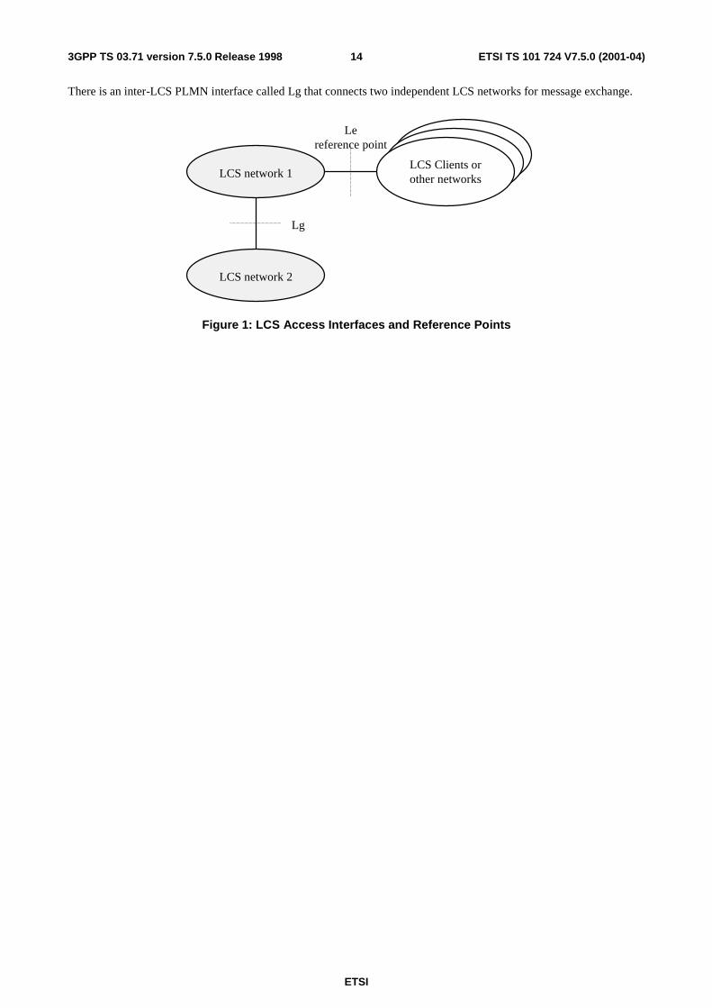
5.1 LCS access interfaces and reference points There is one reference point between the LCS PLMN server and LCS client called Le. Its protocol specifics are for further study. There may be more than a single LCS network interface to several different LCS clients or other networks. These networks may both differ in ownership as well as in communications protocol. The network operator should define and negotiate interconnect with each external LCS client or other network.
An interface differs from a reference point in that an interface is defined where specific LCS information is exchanges and needs to be fully recognized.
ETSI
ETSI TS 101 724 V7.5.0 (2001-04)143GPP TS 03.71 version 7.5.0 Release 1998
There is an inter-LCS PLMN interface called Lg that connects two independent LCS networks for message exchange.
Lereference point
LCS network 1
LCS network 2
LCS Clients orother networks
Lg
Figure 1: LCS Access Interfaces and Reference Points
ETSI
ETSI TS 101 724 V7.5.0 (2001-04)153GPP TS 03.71 version 7.5.0 Release 1998
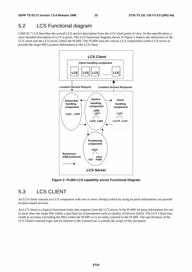
5.2 LCS Functional diagram GSM 02.71 [2] describes the overall LCS service description from the LCS client point of view. In this specification, a more detailed description of LCS is given. The LCS functional diagram shown in Figure 2 depicts the interaction of the LCS client and the LCS server within the PLMN. The PLMN uses the various LCS components within LCS server to provide the target MS Location Information to the LCS client.
Location component
Location Service Request Location Service Response
System
handling
component
LMMF LSCF
LSOF- LSBF
LCS Server
Positioningcomponent
PRCF
PCF PSMF
Subscriberhandlingcomponent
LSAF -- LSPF
Client
handlingcomponent
LCCF
LCCTF LCAF
Resources:GSM protocols
LCS Client
Client handling component
LCF2 LCF1 LCF3 LCFn……...
PRAF
Figure 2: PLMN LCS capability server Functional Diagram
5.3 LCS CLIENT An LCS client contains an LCS component with one or more client(s) which by using location information can provide location based services.
An LCS client is a logical functional entity that requests from the LCS server in the PLMN location information for one or more than one target MS within a specified set of parameters such as Quality of Service (QoS). The LCS Client may reside in an entity (including the MS) within the PLMN or in an entity external to the PLMN. The specification of the LCS Client’s internal logic and its relation to the external use is outside the scope of this document.
ETSI
ETSI TS 101 724 V7.5.0 (2001-04)163GPP TS 03.71 version 7.5.0 Release 1998
5.3.1 LCS Component
5.3.1.1 Location Client Function (LCF)
The Location Client Function (LCF) provides a logical interface between the LCS client and the LCS server. . This function is responsible for requesting location information for one or more MEs/MSs with a specified "QoS" and receiving a response, which contains either location information or a failure indicator.
5.4 LCS Server
5.4.1 Client handling component
5.4.1.1 Location Client Control Function (LCCF)
The Location Client Control Function (LCCF) manages the external interface towards LCF. . The LCCF identifies the LCS client within the GSM PLMN by requesting client verification and authorization ( i.e. verifies that the LCS client is allowed to position the subscriber) through interaction with the Location Client Authorization Function (LCAF) . The LCCF handles mobility management for location services (LCS) e.g., forwarding of positioning requests to VMSC. The LCCF determines if the final positioning estimate satisfies the QoS for the purpose of retry/reject. The LCCF provides flow control of positioning requests between simultaneous positioning requests. It may order the Location Client Coordinate Transformation Function (LCCTF) to perform a transformation to local coordinates. It also generates charging and billing related data for LCS via the Location System Billing Function (LSBF).
5.4.1.2 Location Client Authorization Function (LCAF)
The Location Client Authorization Function (LCAF) is responsible for providing access and subscription authorization to a client. Specifically, it provides authorization to a LCS client requesting access to the network and authorizes the subscription of a client. LCAF provides authorization to a LCS client requesting Location Information of a specific MS.
5.4.1.2.1 Access Subfunction
An Access Subfunction enables LCS clients to access LCS services. This subfunction provides verification and authorization of the requesting client.
When a LCS is requested, the Access Subfunction uses the information stored in the LCS client subscription profile to verify that:
- the LCS client is registered; and
- the LCS client is authorized to use the specified LCS request type;
- the LCS client is allowed to request location information for the subscriber(s) specified in the LCS request;
5.4.1.2.2 Subscription Subfunction
The LCS client Subscription profile shall contain a minimum set of parameters assigned on per LCS client basis for an agreed contractual period. The LCS client profile shall contain the following set of access parameters:
- LCS client identity;
- Allowed LCS request types (i.e. LIR, LDR or both);
- Maximum number of subscribers allowed in a single LCS request;
- Priority;
- Position override indicator;
- State(s);
ETSI
ETSI TS 101 724 V7.5.0 (2001-04)173GPP TS 03.71 version 7.5.0 Release 1998
- Event(s) (applicable to LDR requests only );
- Local coordinate system;
- LCS client access barring list (optional);
- PLMN access barring list applicability.
For certain authorized LCS client internal to the PLMN, a subscription profile is unnecessary. These clients are empowered to access any defined service that is not barred for an MS subscriber. This permits positioning of emergency calls without the need for pre-subscription.
5.4.2 System handling component
5.4.2.1 LMU Mobility Management Function (LMMF)
The LMU Mobility Management Function (LMMF) is responsible for maintaining the operational status of LMUs and registering each LMU in an SMLC. Operation of the LMMF is independent of other logical LCS functions and its output is provided to the PRCF. The LMMF only applies to Type A LMUs.
5.4.2.2 Location System Control Function (LSCF)
The Location System Control Function (LSCF) is responsible for coordinating location requests. This function manages call-related and non-call-related positioning requests of GSM LCS and allocates network resources for handling them. The LSCF retrieves MS classmark for the purpose of determining a positioning method. The LSCF performs call setup if required as part of a LCS e.g., putting the ME in a dedicated mode and obtains Cell-ID. It also caters for coordinating resources and activities with regard to requests related to providing assistance data needed for positioning. This function interfaces with the LCCF, LSPF, LSBF and PRCF. Using these interfaces, it conveys positioning requests to the PRCF, relays positioning data to the LCCF and passes charging related data to the LSBF.
5.4.2.3 Location System Billing Function (LSBF)
The Location System Billing Function (LSBF) is responsible for charging and billing activity within the network related to location services (LCS). This includes charging and billing of both clients and subscribers. Specifically, it collects charging related data and data for accounting between PLMNs.
5.4.2.4 Location Client Coordinate Transformation Function (LCCTF)
The Location Client Coordinate Transformation Function (LCCTF) provides conversion of a location estimate expressed according to a universal latitude and longitude system into an estimate expressed according to a local geographic system understood by the LCF and known as location information. The local system required for a particular LCF will be either known from subscription information or explicitly indicated by the LCF.
5.4.2.5 Location System Operations Function (LSOF)
The Location System Operations Function (LSOF) is responsible for provisioning of data, positioning capabilities, data related to clients and subscription (LCS client data and MS data), validation, fault management and performance management of GSM LCS.
5.4.2.6 Location System Broadcast Function (LSBcF)
The Location System Broadcast Function (LSBcF) provides broadcast capability. The LSBcF capability is only used when broadcast data is required for E-OTD or A-GPS positioning methods.
ETSI
ETSI TS 101 724 V7.5.0 (2001-04)183GPP TS 03.71 version 7.5.0 Release 1998
5.4.3 Subscriber Component
5.4.3.1 Location Subscriber Authorization Function (LSAF)
The Location Subscriber Authorization Function (LSAF) is responsible for authorizing the provision of a location service (LCS) for a particular mobile. Specifically, this function validates that a GSM LCS can be applied to a given subscriber. The LSAF verifies the client MS’s subscription.
5.4.3.2 Location Subscriber Privacy Function (LSPF)
The Location Subscriber Privacy function is responsible performs all privacy related authorizations. For an target MS it shall authorize the positioning request versus the privacy options of the target MS, if any.
5.4.4 Positioning component
5.4.4.1 Positioning Radio Coordination Function (PRCF)
The Positioning Radio Control Function (PRCF) manages the positioning of a mobile through overall coordination and scheduling of resources to perform positioning measurements. This function interfaces with the PSMF and PCF and possibly with a PRAF. The PRCF determines the positioning method to be used based on the QoS, the capabiities of the network, and the MS’s location capabilities. It determines which PSMFs to be involved or what to measure, and obtains processed signal measurements from PSMF. Next, it packs the signal measurement data from the PSMF into a certain format and forwards it to the PCF.
5.4.4.2 Positioning Radio Assistance Function (PRAF)
The Positioning Radio Assistance Function (PRAF) provides additional support for the PRCF when radio coordination is distributed among multiple network elements. A particular function of the PRAF for network based position methods is to induce positioning signals from the target MS. For mobile based and mobile assisted position methods, the PRAF could induce position signals from the network or from some other external reference source.
5.4.4.3 Positioning Calculation Function (PCF)
The Positioning Calculation Function (PCF) is responsible for calculating the position of the mobile. It obtains BTS related data e.g., BTS geographic co-ordinates and stores this data. This function applies an algorithmic computation on the collected signal measurements to compute the final location estimate and accuracy. It also supports conversion of mobile’s location estimate between different geodatic reference systems.
5.4.4.4 Positioning Signal Measurement Function (PSMF)
The Positioning Signal Measurement Function (PSMF) is responsible for gathering uplink or downlink radio signal measurements for calculation of a mobile’s position. These measurements can be positioning related or ancillary.
5.5 Information Flows between Client and Server Other types of national specific information flows may be supported in addition to the information flow specified here.
Any of the information flows here indicated may not be externally realized if the information does not flow over an open interface. On the other hand, if a flow goes over an open interface, it shall abide to a well-defined protocol, which will be further specified in other relevant specifications.
5.5.1 Location Service Request
Via the Location Service Request, the LCS client communicates with the LCS server to request for the location information of one or more than one MS within a specified quality of service. There exist two types of location service requests:
- Location Immediate Request (LIR); and
ETSI
ETSI TS 101 724 V7.5.0 (2001-04)193GPP TS 03.71 version 7.5.0 Release 1998
- Location Deferred Request (LDR).
The following attributes are identified for Location Service Request information flow:
- Target MS;
- LCS identity;
- State (idle, dedicated)
- Event (applicable to LDR requests only);
- Quality of Service information;
- Local coordinate system;
- Geographical area.
5.5.2 Location Service Response
The Location Service Response is sent to the LCS client as the result of the Location Service Request by the LCS Server:
Immediate Response; and
Deferred Response;
These deferred responses can be either single or periodic.
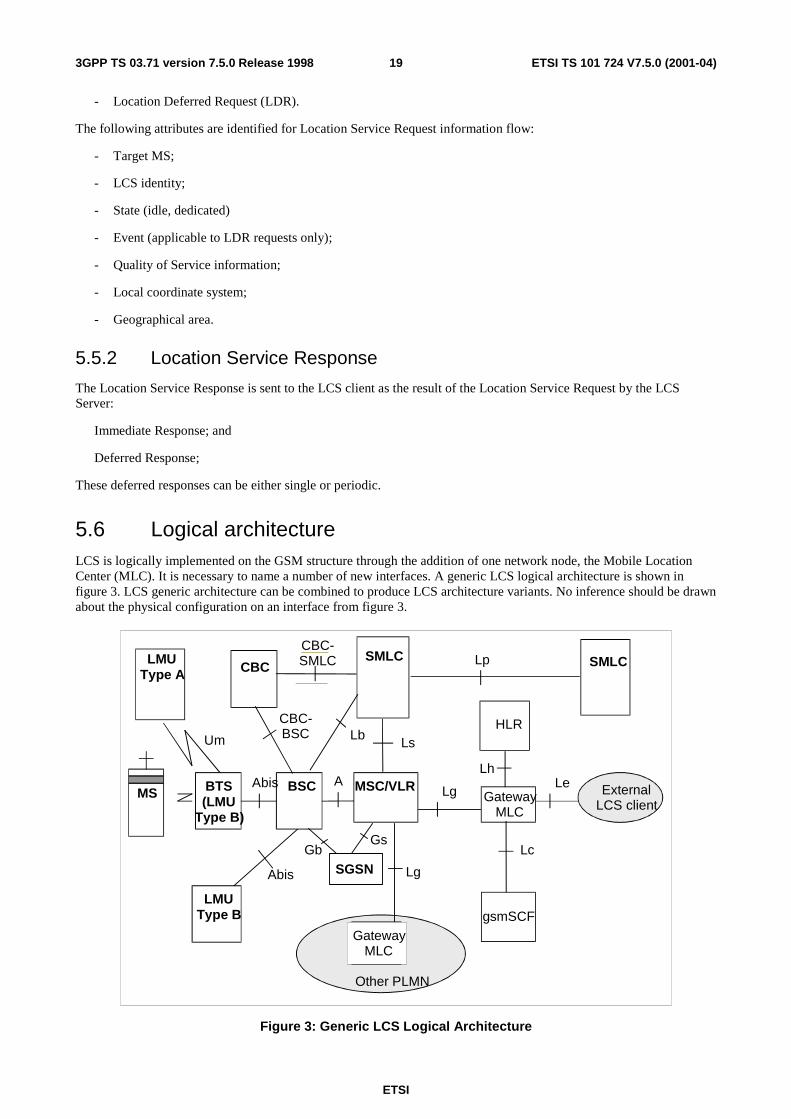
5.6 Logical architecture LCS is logically implemented on the GSM structure through the addition of one network node, the Mobile Location Center (MLC). It is necessary to name a number of new interfaces. A generic LCS logical architecture is shown in figure 3. LCS generic architecture can be combined to produce LCS architecture variants. No inference should be drawn about the physical configuration on an interface from figure 3.
MS MSC/VLR
HLR
SMLC
LeLg
Lg
Lh
Other PLMN
Um Ls
BSC AAbis
Lb
SMLCLp
Abis
gsmSCF
Lc
CBCLMU
Type A
CBC-SMLC
CBC-BSC
BTS(LMU
Type B)
ExternalLCS client
GatewayMLC
GatewayMLC
LMUType B
SGSN
GsGb
Figure 3: Generic LCS Logical Architecture
ETSI
ETSI TS 101 724 V7.5.0 (2001-04)203GPP TS 03.71 version 7.5.0 Release 1998
5.6.1 BSS
The BSS is involved in the handling of various positioning procedures. Specific BSS functionality is specified in each of the positioning procedures section.
5.6.2 LCS Client
The LCS client is outside the scope of this standard.
5.6.3 GMLC
The Gateway Mobile Location Center (GMLC) contains functionality required to support LCS. In one PLMN, there may be more than one GMLC.
The GMLC is the first node an external LCS client accesses in a GSM PLMN (i.e. the Le reference point is supported by the GMLC). The GMLC may request routing information from the HLR via the Lh interface. After performing registration authorization, it sends positioning requests to and receives final location estimates from the VMSC via the Lg interface.
5.6.4 SMLC
The Serving Mobile Location Center (SMLC) contains functionality required to support LCS. In one PLMN, there may be more than one SMLC.
The SMLC manages the overall coordination and scheduling of resources required to perform positioning of a mobile. It also calculates the final location estimate and accuracy.
Two types of SMLC are possible:
NSS based SMLC: supports the Ls interface.
BSS based SMLC: supports the Lb interface.
An NSS based SMLC supports positioning of a target MS via signaling on the Ls interface to the visited MSC. A BSS based SMLC supports positioning via signaling on the Lb interface to the BSC serving the target MS. Both types of SMLC may support the Lp interface to enable access to information and resources owned by another SMLC.
The SMLC controls a number of LMUs for the purpose of obtaining radio interface measurements to locate or help locate MS subscribers in the area that it serves. The SMLC is administered with the capabilities and types of measurement produced by each of its LMUs. Signaling between an NSS based SMLC and LMU is transferred via the MSC serving the LMU using the Ls interface and either the Um interface for a Type A LMU or the Abis interface for a Type B LMU. Signaling between a BSS based SMLC and LMU is transferred via the BSC that serves or controls the LMU using the Lb interface and either the Um interface for a Type A LMU or the Abis interface for a Type B LMU.
The SMLC and GMLC functionality may be combined in the same physical node, combined in existing physical nodes, or reside in different nodes.
For Location Services, when a Cell Broadcast Center (CBC) is associated with a BSC, the SMLC may interface to a CBC in order to broadcast assistance data using existing cell broadcast capabilities. The SMLC shall behave as a user, Cell Broadcast Entity, to the CBC (refer to GSM.03.41).
5.6.5 MS
The MS may be involved in the various positioning procedures. Specific MS involvement is specified in each of the positioning procedures section.
ETSI
ETSI TS 101 724 V7.5.0 (2001-04)213GPP TS 03.71 version 7.5.0 Release 1998
5.6.6 LMU
An LMU makes radio measurements to support one or more positioning methods. These measurements fall into one of two categories:
a) Location measurements specific to one MS used to compute the location of this MS
b) Assistance measurements specific to all MSs in a certain geographic area
All location and assistance measurements obtained by an LMU are supplied to a particular SMLC associated with the LMU. Instructions concerning the timing, the nature and any periodicity of these measurements are either provided by the SMLC or are pre-administered in the LMU.
Two types of LMU are defined:
Type A LMU: accessed over the normal GSM air interface.
Type B LMU: accessed over the Abis interface.
A type A LMU is accessed exclusively over the GSM air interface (Um interface): there is no wired connection to any other network element. A type A LMU has a serving BTS and BSC that provide signaling access to a controlling SMLC. With an NSS based SMLC, a type A LMU also has a serving MSC and VLR and a subscription profile in an HLR. A type A LMU always has a unique IMSI and supports all radio resource and mobility management functions of the GSM air interface that are necessary to support signaling using an SDCCH to the SMLC. A type A LMU supports those connection management functions necessary to support LCS signaling transactions with the SMLC and may support certain call control functions of to support signaling to an SMLC using a circuit switched data connection.
NOTE: A network operator may assign specific ranges of IMSI for its LMUs and may assign certain digits within the IMSI to indicate the associated SMLC. Certain digits in the IMSI may also be used as a local identifier for an LMU within an SMLC.
To ensure that a Type A LMU and its associated SMLC can always access one another, an LMU may be homed (camped) on a particular cell site or group of cell sites belonging to one BSC or one MSC. For any Type A LMU with a subscription profile in an HLR (applies only with an NSS based SMLC), a special profile is used indicating no supplementary services, except possibly SMS-PP MT (for data download via the SIM application toolkit), and barring of all incoming and possibly outgoing calls. An identifier in the HLR profile also distinguishes an LMU from a normal MS. All other data specific to an LMU is administered in the LMU and in its associated SMLC.
A Type B LMU is accessed over the Abis interface from a BSC. The LMU may be either a standalone network element addressed using some pseudo-cell ID or connected to or integrated in a BTS. Signaling to a Type B LMU is by means of messages routed through the controlling BSC for a BSS based SMLC or messages routed through a controlling BSC and MSC for an NSS based SMLC.
The following assistance measurements obtained by an LMU have a generic status in being usable by more than one position method:
Radio Interface Timing measurements – comprise Absolute Time Differences (ATDs) or Real Time Differences (RTDs) of the signals transmitted by Base Stations, where timing differences are measured relative to either some absolute time difference (ATD) or the signals of another Base Station (RTD).
5.6.7 MSC
The MSC contains functionality responsible for MS subscription authorization and managing call-related and non-call related positioning requests of GSM LCS. The MSC is accessible to the GMLC via the Lg interface and the SMLC via the Ls interface. If connected to SGSN through the Gs interface, it checks whether the mobile station is GPRS attached to decide whether to page the mobile station on the A or Gs interface.
5.6.8 HLR
The HLR contains LCS subscription data and routing information. The HLR is accessible from the GMLC via the Lh interface. For roaming MSs, HLR may be in a different PLMN that the current SMLC.
ETSI
ETSI TS 101 724 V7.5.0 (2001-04)223GPP TS 03.71 version 7.5.0 Release 1998
5.6.9 gsmSCF
The Lc interface supports CAMEL access to LCS and is applicable only in CAMEL phase 3. The procedures and signaling associated with it are defined in GSM 03.78 and GSM 09.02, respectively.
5.6.10 LMU and SMLC association
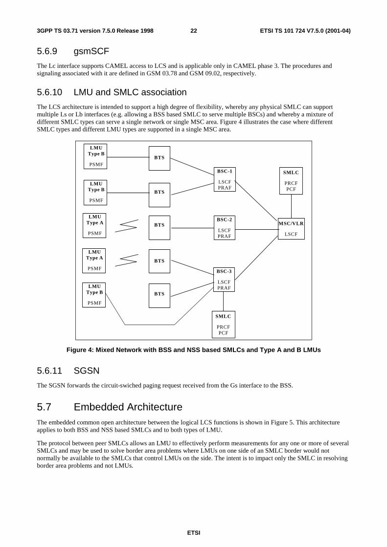
The LCS architecture is intended to support a high degree of flexibility, whereby any physical SMLC can support multiple Ls or Lb interfaces (e.g. allowing a BSS based SMLC to serve multiple BSCs) and whereby a mixture of different SMLC types can serve a single network or single MSC area. Figure 4 illustrates the case where different SMLC types and different LMU types are supported in a single MSC area.
BTS
MSC/VLR
LSCF
SMLC
PRCFPCF
BSC-1
LSCFPRAF
BSC-2
LSCFPRAF
BSC-3
LSCFPRAF
BTS
BTS
BTS
BTS
LMUType A
PSMF
SMLC
PRCFPCF
LMUType A
PSMF
LMUType B
PSMF
LMUType B
PSMF
LMUType B
PSMF
Figure 4: Mixed Network with BSS and NSS based SMLCs and Type A and B LMUs
5.6.11 SGSN
The SGSN forwards the circuit-swiched paging request received from the Gs interface to the BSS.
5.7 Embedded Architecture The embedded common open architecture between the logical LCS functions is shown in Figure 5. This architecture applies to both BSS and NSS based SMLCs and to both types of LMU.
The protocol between peer SMLCs allows an LMU to effectively perform measurements for any one or more of several SMLCs and may be used to solve border area problems where LMUs on one side of an SMLC border would not normally be available to the SMLCs that control LMUs on the side. The intent is to impact only the SMLC in resolving border area problems and not LMUs.
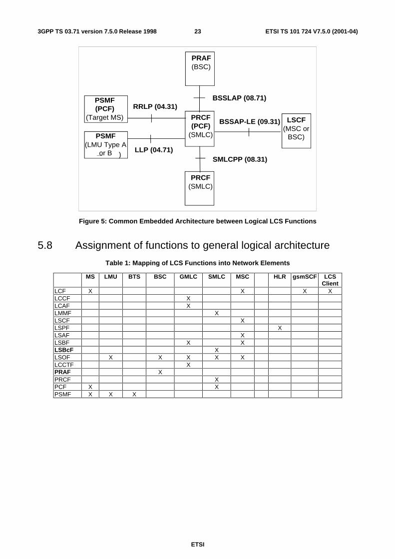
ETSI
ETSI TS 101 724 V7.5.0 (2001-04)233GPP TS 03.71 version 7.5.0 Release 1998
)LLP (04.71)
BSSAP-LE (09.31)
BSSLAP (08.71)
SMLCPP (08.31)
RRLP (04.31)PSMF(PCF)
(Target MS)
PRAF(BSC)
PRCF(PCF)
(SMLC)
LSCF(MSC or
BSC)
PRCF(SMLC)
PSMF(LMU Type A
or B
Figure 5: Common Embedded Architecture between Logical LCS Functions
5.8 Assignment of functions to general logical architecture
Table 1: Mapping of LCS Functions into Network Elements
MS LMU BTS BSC GMLC SMLC MSC HLR gsmSCF LCS Client
LCF X X X X LCCF X LCAF X LMMF X LSCF X LSPF X LSAF X LSBF X X LSBcF X LSOF X X X X X LCCTF X PRAF X PRCF X PCF X X PSMF X X X
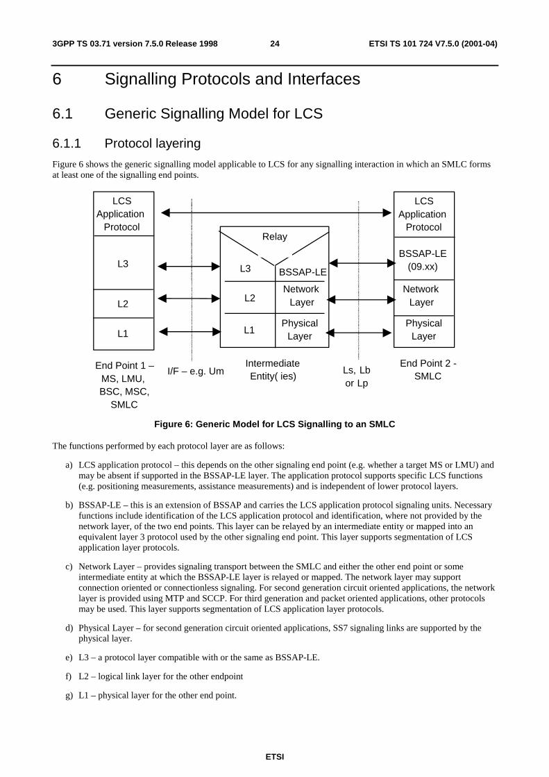
ETSI
ETSI TS 101 724 V7.5.0 (2001-04)243GPP TS 03.71 version 7.5.0 Release 1998
6 Signalling Protocols and Interfaces
6.1 Generic Signalling Model for LCS
6.1.1 Protocol layering
Figure 6 shows the generic signalling model applicable to LCS for any signalling interaction in which an SMLC forms at least one of the signalling end points.
End Point 1 –MS, LMU,BSC, MSC,
SMLC
IntermediateEntity( ies)
End Point 2 -SMLC
LCSApplication
Protocol
BSSAP-LE(09.xx)BSSAP-LE
NetworkLayer
L3
L2
L1
Relay
I/F – e.g. Um Ls, Lbor Lp
L3
L2
L1
LCSApplication
Protocol
NetworkLayer
PhysicalLayer
PhysicalLayer
Figure 6: Generic Model for LCS Signalling to an SMLC
The functions performed by each protocol layer are as follows:
a) LCS application protocol – this depends on the other signaling end point (e.g. whether a target MS or LMU) and may be absent if supported in the BSSAP-LE layer. The application protocol supports specific LCS functions (e.g. positioning measurements, assistance measurements) and is independent of lower protocol layers.
b) BSSAP-LE – this is an extension of BSSAP and carries the LCS application protocol signaling units. Necessary functions include identification of the LCS application protocol and identification, where not provided by the network layer, of the two end points. This layer can be relayed by an intermediate entity or mapped into an equivalent layer 3 protocol used by the other signaling end point. This layer supports segmentation of LCS application layer protocols.
c) Network Layer – provides signaling transport between the SMLC and either the other end point or some intermediate entity at which the BSSAP-LE layer is relayed or mapped. The network layer may support connection oriented or connectionless signaling. For second generation circuit oriented applications, the network layer is provided using MTP and SCCP. For third generation and packet oriented applications, other protocols may be used. This layer supports segmentation of LCS application layer protocols.
d) Physical Layer – for second generation circuit oriented applications, SS7 signaling links are supported by the physical layer.
e) L3 – a protocol layer compatible with or the same as BSSAP-LE.
f) L2 – logical link layer for the other endpoint
g) L1 – physical layer for the other end point.
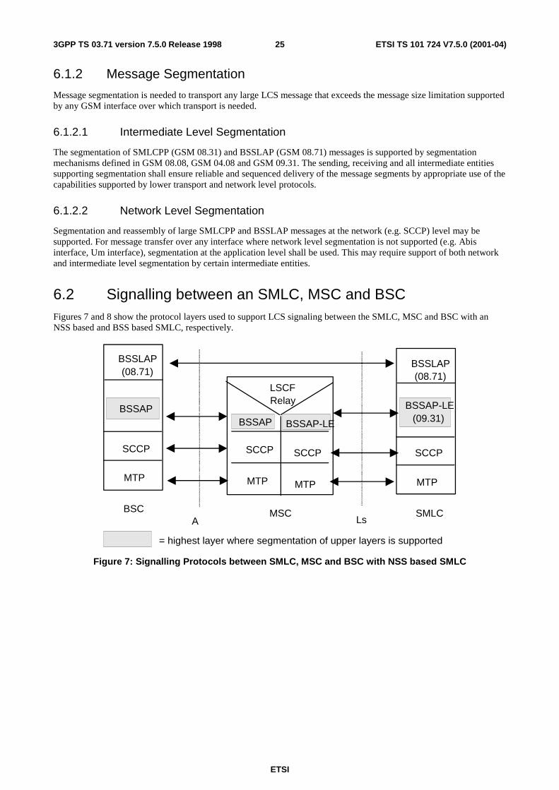
ETSI
ETSI TS 101 724 V7.5.0 (2001-04)253GPP TS 03.71 version 7.5.0 Release 1998
6.1.2 Message Segmentation
Message segmentation is needed to transport any large LCS message that exceeds the message size limitation supported by any GSM interface over which transport is needed.
6.1.2.1 Intermediate Level Segmentation
The segmentation of SMLCPP (GSM 08.31) and BSSLAP (GSM 08.71) messages is supported by segmentation mechanisms defined in GSM 08.08, GSM 04.08 and GSM 09.31. The sending, receiving and all intermediate entities supporting segmentation shall ensure reliable and sequenced delivery of the message segments by appropriate use of the capabilities supported by lower transport and network level protocols.
6.1.2.2 Network Level Segmentation
Segmentation and reassembly of large SMLCPP and BSSLAP messages at the network (e.g. SCCP) level may be supported. For message transfer over any interface where network level segmentation is not supported (e.g. Abis interface, Um interface), segmentation at the application level shall be used. This may require support of both network and intermediate level segmentation by certain intermediate entities.
6.2 Signalling between an SMLC, MSC and BSC Figures 7 and 8 show the protocol layers used to support LCS signaling between the SMLC, MSC and BSC with an NSS based and BSS based SMLC, respectively.
BSC MSC SMLC
BSSLAP(08.71)
SCCP
MTP
SCCP
MTP
SCCP
MTP
LSCFRelay
A Ls
BSSLAP(08.71)
SCCP
MTP
BSSAPBSSAP BSSAP-LE (09.31)
BSSAP-LE
= highest layer where segmentation of upper layers is supported
Figure 7: Signalling Protocols between SMLC, MSC and BSC with NSS based SMLC
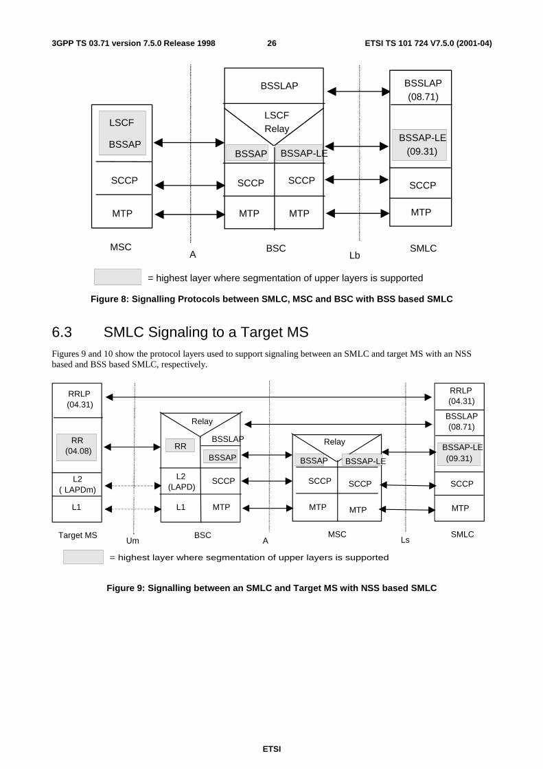
ETSI
ETSI TS 101 724 V7.5.0 (2001-04)263GPP TS 03.71 version 7.5.0 Release 1998
BSCMSC
SCCP
MTP
SCCP
MTPMTP
SCCP
BSSLAP
LSCFRelay
A LbSMLC
BSSLAP(08.71)
SCCP
MTP
BSSAP
LSCF
BSSAP BSSAP-LE (09.31)BSSAP-LE
= highest layer where segmentation of upper layers is supported
Figure 8: Signalling Protocols between SMLC, MSC and BSC with BSS based SMLC
6.3 SMLC Signaling to a Target MS Figures 9 and 10 show the protocol layers used to support signaling between an SMLC and target MS with an NSS based and BSS based SMLC, respectively.
= highest layer where segmentation of upper layers is supported
Target MS BSC MSC SMLC
L1
L2( LAPDm)
RRLP(04.31)
RRLP(04.31)
SCCP
MTP
SCCP
MTP
SCCP
MTP
SCCP
MTPL1
L2(LAPD)
Relay
Um A Ls
BSSLAP(08.71)
BSSLAP
Relay
RR(04.08) RR
BSSAP BSSAP BSSAP-LE
BSSAP-LE(09.31)
Figure 9: Signalling between an SMLC and Target MS with NSS based SMLC
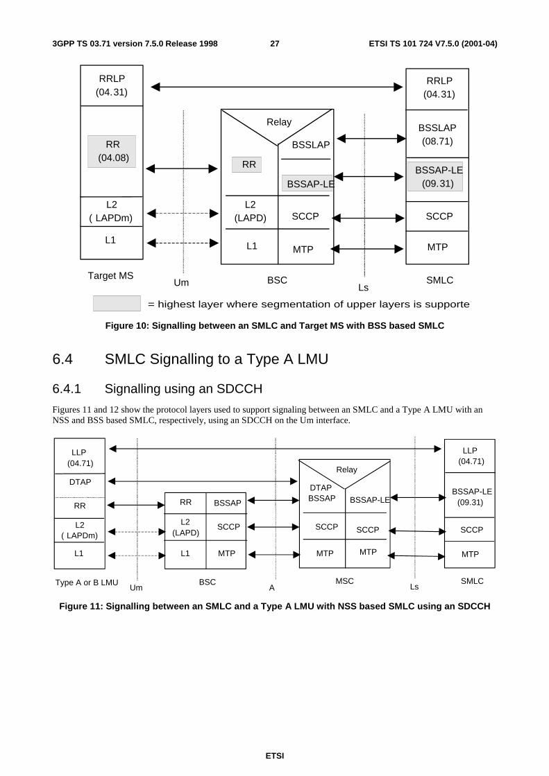
ETSI
ETSI TS 101 724 V7.5.0 (2001-04)273GPP TS 03.71 version 7.5.0 Release 1998
= highest layer where segmentation of upper layers is supporte
Target MS BSC SMLC
L1
L2( LAPDm)
RRLP(04.31)
RRLP(04.31)
SCCP
MTP
SCCP
MTP
L2(LAPD)
L1
Um Ls
BSSLAP
RelayBSSLAP(08.71)RR
(04.08)RR
BSSAP-LEBSSAP-LE
(09.31)
Figure 10: Signalling between an SMLC and Target MS with BSS based SMLC
6.4 SMLC Signalling to a Type A LMU
6.4.1 Signalling using an SDCCH
Figures 11 and 12 show the protocol layers used to support signaling between an SMLC and a Type A LMU with an NSS and BSS based SMLC, respectively, using an SDCCH on the Um interface.
Type A or B LMU BSC MSC SMLC
L1
L2( LAPDm)
DTAP
LLP(04.71)
LLP(04.71)
BSSAP-LE(09.31)
SCCP
MTP
BSSAP-LE
SCCP
MTP
DTAPBSSAP
SCCP
MTP
SCCP
MTPL1
L2(LAPD)
RR
Relay
Um A Ls
RR BSSAP
Figure 11: Signalling between an SMLC and a Type A LMU with NSS based SMLC using an SDCCH
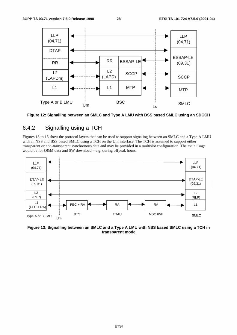
ETSI
ETSI TS 101 724 V7.5.0 (2001-04)283GPP TS 03.71 version 7.5.0 Release 1998
Type A or B LMU BSC SMLC
L1
L2(LAPDm)
DTAP
LLP(04.71)
LLP(04.71)
BSSAP-LE(09.31)
SCCP
MTP
SCCP
MTPL1
L2(LAPD)
RR
Um Ls
RR BSSAP:-LE
Figure 12: Signalling between an SMLC and Type A LMU with BSS based SMLC using an SDCCH
6.4.2 Signalling using a TCH
Figures 13 to 15 show the protocol layers that can be used to support signaling between an SMLC and a Type A LMU with an NSS and BSS based SMLC using a TCH on the Um interface. The TCH is assumed to support either transparent or non-transparent synchronous data and may be provided in a multislot configuration. The main usage would be for O&M data and SW download – e.g. during offpeak hours.
Type A or B LMU SMLC
L1(FEC + RA)
L2(RLP)
DTAP-LE(09.31)
LLP(04.71)
LLP(04.71)
DTAP-LE(09.31)
L2(RLP)
L1
Um
FEC + RA
BTS
RA
TRAU
RA
MSC IWF
Figure 13: Signalling between an SMLC and a Type A LMU with NSS based SMLC using a TCH in transparent mode
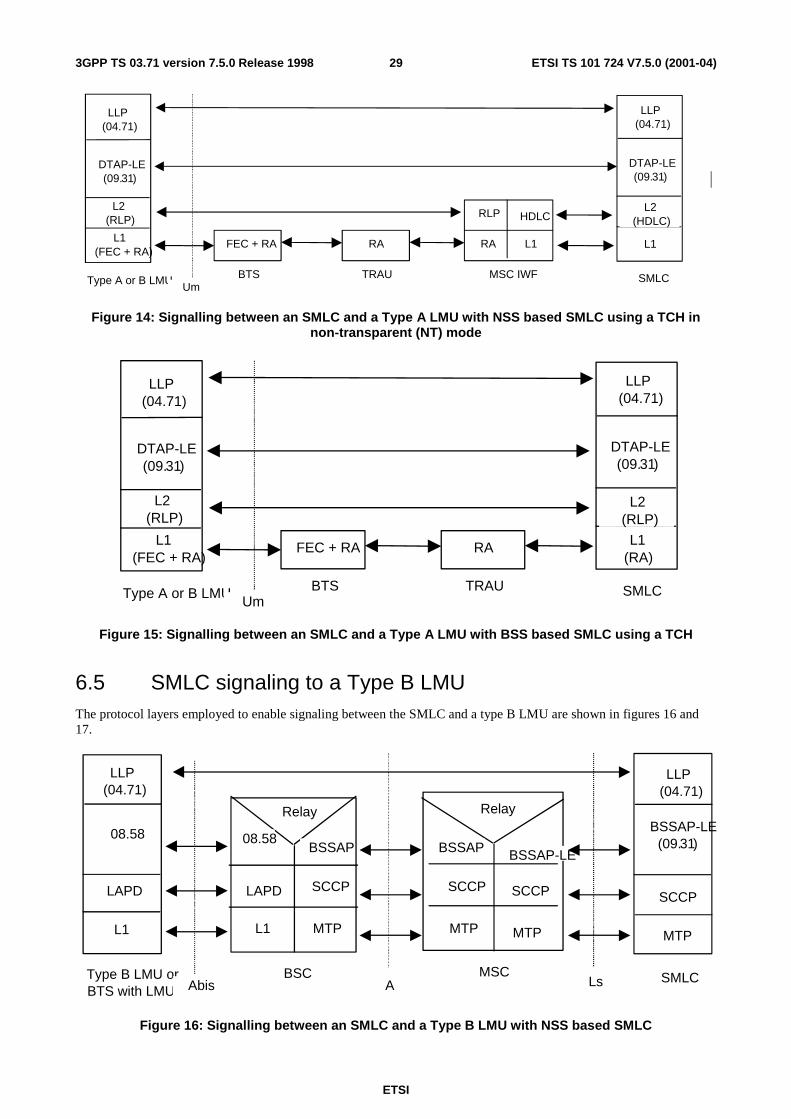
ETSI
ETSI TS 101 724 V7.5.0 (2001-04)293GPP TS 03.71 version 7.5.0 Release 1998
Type A or B LMU SMLC
L1(FEC + RA)
L2(RLP)
DTAP-LE(09.31)
LLP(04.71)
LLP(04.71)
DTAP-LE(09.31)
L2(HDLC)
L1
Um
FEC + RA
BTS
RA
TRAU
RA
MSC IWF
RLP HDLC
L1
Figure 14: Signalling between an SMLC and a Type A LMU with NSS based SMLC using a TCH in non-transparent (NT) mode
Type A or B LMU SMLC
L1(FEC + RA)
L2(RLP)
DTAP-LE(09.31)
LLP(04.71)
LLP(04.71)
DTAP-LE(09.31)
L2(RLP)
L1(RA)
Um
FEC + RA
BTS
RA
TRAU
Figure 15: Signalling between an SMLC and a Type A LMU with BSS based SMLC using a TCH
6.5 SMLC signaling to a Type B LMU The protocol layers employed to enable signaling between the SMLC and a type B LMU are shown in figures 16 and 17.
Type B LMU orBTS with LMU
BSC MSC SMLC
L1
LAPD
08.58
LLP(04.71)
LLP(04.71)
BSSAP-LE(09.31)
SCCP
MTP
BSSAP-LE
SCCP
MTP
BSSAP
SCCP
MTP
BSSAP
SCCP
MTPL1
LAPD
08.58
RelayRelay
A LsAbis
Figure 16: Signalling between an SMLC and a Type B LMU with NSS based SMLC
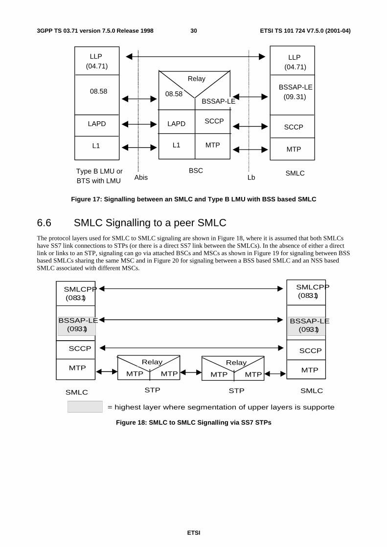
ETSI
ETSI TS 101 724 V7.5.0 (2001-04)303GPP TS 03.71 version 7.5.0 Release 1998
Type B LMU orBTS with LMU
BSC SMLC
L1
LAPD
08.58
LLP(04.71)
LLP(04.71)
BSSAP-LE(09.31)
SCCP
MTP
BSSAP-LE
SCCP
MTPL1
LAPD
08.58
Relay
Abis Lb
Figure 17: Signalling between an SMLC and Type B LMU with BSS based SMLC
6.6 SMLC Signalling to a peer SMLC The protocol layers used for SMLC to SMLC signaling are shown in Figure 18, where it is assumed that both SMLCs have SS7 link connections to STPs (or there is a direct SS7 link between the SMLCs). In the absence of either a direct link or links to an STP, signaling can go via attached BSCs and MSCs as shown in Figure 19 for signaling between BSS based SMLCs sharing the same MSC and in Figure 20 for signaling between a BSS based SMLC and an NSS based SMLC associated with different MSCs.
SMLC SMLC
MTP
SCCP
SMLCPP(08.31)
SMLCPP(08.31)
SCCP
MTP
STP
MTP
Relay
MTP
STP
MTP
Relay
MTP
= highest layer where segmentation of upper layers is supporte
BSSAP-LE(09.31)(09.31)
BSSAP-LE
Figure 18: SMLC to SMLC Signalling via SS7 STPs
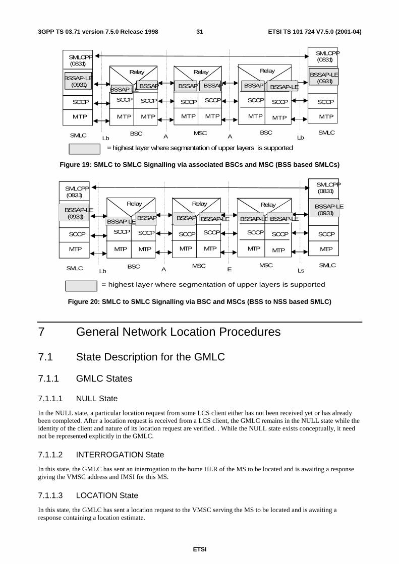
ETSI
ETSI TS 101 724 V7.5.0 (2001-04)313GPP TS 03.71 version 7.5.0 Release 1998
SMLC MSC BSC SMLC
MTP
SCCP
SMLCPP(08.31)
SMLCPP(08.31)
SCCP
MTP
SCCP
MTP
SCCP
MTP
SCCP
MTPMTP
SCCP
RelayRelay
A A LbBSC
SCCP
MTPMTP
SCCP
Relay
Lb
(09.31)BSSAP-LE
BSSAP-LEBSSAP BSSAP BSSAP BSSAP BSSAP-LE
(09.31)BSSAP-LE
= highest layer where segmentation of upper layers is supported
Figure 19: SMLC to SMLC Signalling via associated BSCs and MSC (BSS based SMLCs)
SMLC MSC MSC SMLC
MTP
SCCP
SMLCPP(08.31)
SMLCPP(08.31)
SCCP
MTP
SCCP
MTP
SCCP
MTP
SCCP
MTPMTP
SCCP
RelayRelay
A E LsBSC
SCCP
MTPMTP
SCCP
Relay
Lb
= highest layer where segmentation of upper layers is supported
BSSAP-LE(09.31)
BSSAP-LEBSSAP BSSAP BSSAP-LE BSSAP-LEBSSAP-LE
(09.31)BSSAP-LE
Figure 20: SMLC to SMLC Signalling via BSC and MSCs (BSS to NSS based SMLC)
7 General Network Location Procedures
7.1 State Description for the GMLC
7.1.1 GMLC States
7.1.1.1 NULL State
In the NULL state, a particular location request from some LCS client either has not been received yet or has already been completed. After a location request is received from a LCS client, the GMLC remains in the NULL state while the identity of the client and nature of its location request are verified. . While the NULL state exists conceptually, it need not be represented explicitly in the GMLC.
7.1.1.2 INTERROGATION State
In this state, the GMLC has sent an interrogation to the home HLR of the MS to be located and is awaiting a response giving the VMSC address and IMSI for this MS.
7.1.1.3 LOCATION State
In this state, the GMLC has sent a location request to the VMSC serving the MS to be located and is awaiting a response containing a location estimate.
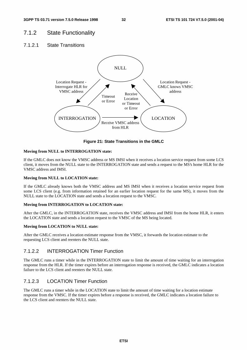
ETSI
ETSI TS 101 724 V7.5.0 (2001-04)323GPP TS 03.71 version 7.5.0 Release 1998
7.1.2 State Functionality
7.1.2.1 State Transitions
NULL
INTERROGATION LOCATION
Location Request -GMLC knows VMSC
addressReceiveLocation
or Timeoutor Error
Timeoutor Error
Receive VMSC addressfrom HLR
Location Request -Interrogate HLR for
VMSC address
Figure 21: State Transitions in the GMLC
Moving from NULL to INTERROGATION state:
If the GMLC does not know the VMSC address or MS IMSI when it receives a location service request from some LCS client, it moves from the NULL state to the INTERROGATION state and sends a request to the MS’s home HLR for the VMSC address and IMSI.
Moving from NULL to LOCATION state:
If the GMLC already knows both the VMSC address and MS IMSI when it receives a location service request from some LCS client (e.g. from information retained for an earlier location request for the same MS), it moves from the NULL state to the LOCATION state and sends a location request to the VMSC.
Moving from INTERROGATION to LOCATION state:
After the GMLC, in the INTERROGATION state, receives the VMSC address and IMSI from the home HLR, it enters the LOCATION state and sends a location request to the VMSC of the MS being located.
Moving from LOCATION to NULL state:
After the GMLC receives a location estimate response from the VMSC, it forwards the location estimate to the requesting LCS client and reenters the NULL state.
7.1.2.2 INTERROGATION Timer Function
The GMLC runs a timer while in the INTERROGATION state to limit the amount of time waiting for an interrogation response from the HLR. If the timer expires before an interrogation response is received, the GMLC indicates a location failure to the LCS client and reenters the NULL state.
7.1.2.3 LOCATION Timer Function
The GMLC runs a timer while in the LOCATION state to limit the amount of time waiting for a location estimate response from the VMSC. If the timer expires before a response is received, the GMLC indicates a location failure to the LCS client and reenters the NULL state.
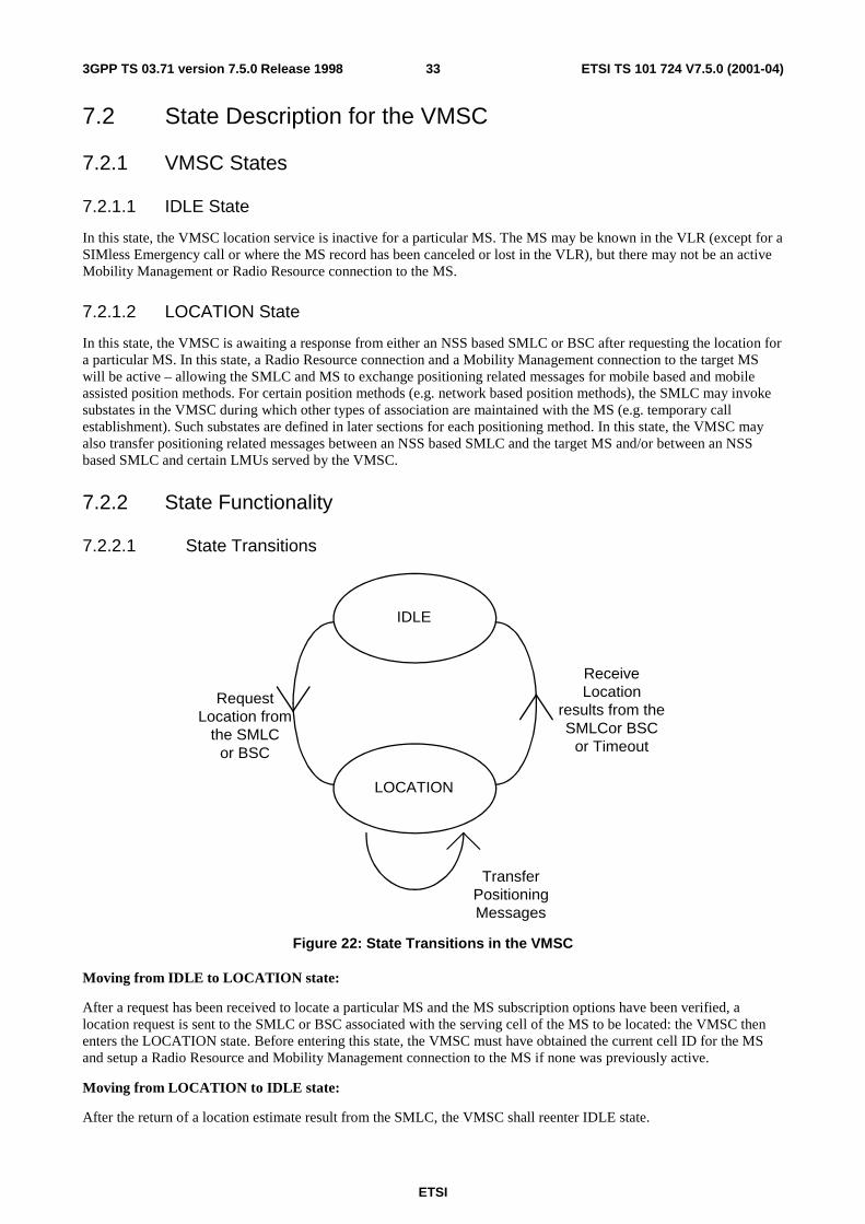
ETSI
ETSI TS 101 724 V7.5.0 (2001-04)333GPP TS 03.71 version 7.5.0 Release 1998
7.2 State Description for the VMSC
7.2.1 VMSC States
7.2.1.1 IDLE State
In this state, the VMSC location service is inactive for a particular MS. The MS may be known in the VLR (except for a SIMless Emergency call or where the MS record has been canceled or lost in the VLR), but there may not be an active Mobility Management or Radio Resource connection to the MS.
7.2.1.2 LOCATION State
In this state, the VMSC is awaiting a response from either an NSS based SMLC or BSC after requesting the location for a particular MS. In this state, a Radio Resource connection and a Mobility Management connection to the target MS will be active – allowing the SMLC and MS to exchange positioning related messages for mobile based and mobile assisted position methods. For certain position methods (e.g. network based position methods), the SMLC may invoke substates in the VMSC during which other types of association are maintained with the MS (e.g. temporary call establishment). Such substates are defined in later sections for each positioning method. In this state, the VMSC may also transfer positioning related messages between an NSS based SMLC and the target MS and/or between an NSS based SMLC and certain LMUs served by the VMSC.
7.2.2 State Functionality
7.2.2.1 State Transitions
LOCATION
IDLE
RequestLocation from
the SMLCor BSC
ReceiveLocation
results from theSMLCor BSC
or Timeout
TransferPositioningMessages
Figure 22: State Transitions in the VMSC
Moving from IDLE to LOCATION state:
After a request has been received to locate a particular MS and the MS subscription options have been verified, a location request is sent to the SMLC or BSC associated with the serving cell of the MS to be located: the VMSC then enters the LOCATION state. Before entering this state, the VMSC must have obtained the current cell ID for the MS and setup a Radio Resource and Mobility Management connection to the MS if none was previously active.
Moving from LOCATION to IDLE state:
After the return of a location estimate result from the SMLC, the VMSC shall reenter IDLE state.
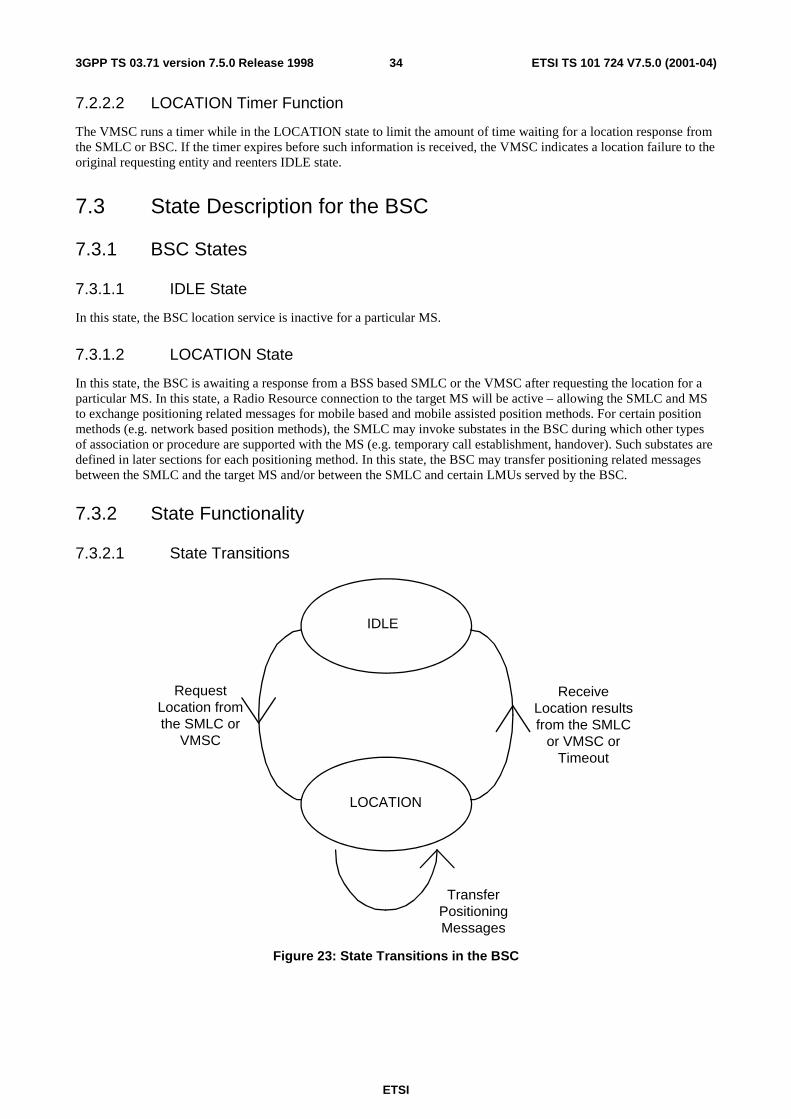
ETSI
ETSI TS 101 724 V7.5.0 (2001-04)343GPP TS 03.71 version 7.5.0 Release 1998
7.2.2.2 LOCATION Timer Function
The VMSC runs a timer while in the LOCATION state to limit the amount of time waiting for a location response from the SMLC or BSC. If the timer expires before such information is received, the VMSC indicates a location failure to the original requesting entity and reenters IDLE state.
7.3 State Description for the BSC
7.3.1 BSC States
7.3.1.1 IDLE State
In this state, the BSC location service is inactive for a particular MS.
7.3.1.2 LOCATION State
In this state, the BSC is awaiting a response from a BSS based SMLC or the VMSC after requesting the location for a particular MS. In this state, a Radio Resource connection to the target MS will be active – allowing the SMLC and MS to exchange positioning related messages for mobile based and mobile assisted position methods. For certain position methods (e.g. network based position methods), the SMLC may invoke substates in the BSC during which other types of association or procedure are supported with the MS (e.g. temporary call establishment, handover). Such substates are defined in later sections for each positioning method. In this state, the BSC may transfer positioning related messages between the SMLC and the target MS and/or between the SMLC and certain LMUs served by the BSC.
7.3.2 State Functionality
7.3.2.1 State Transitions
LOCATION
IDLE
RequestLocation fromthe SMLC or
VMSC
ReceiveLocation resultsfrom the SMLC
or VMSC orTimeout
TransferPositioningMessages
Figure 23: State Transitions in the BSC
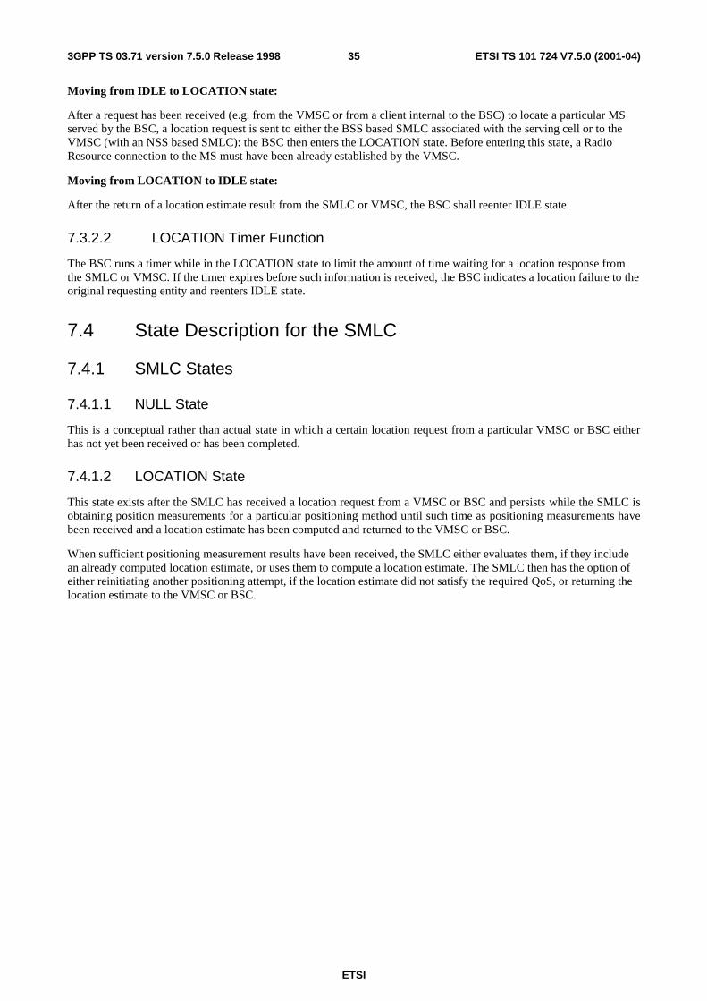
ETSI
ETSI TS 101 724 V7.5.0 (2001-04)353GPP TS 03.71 version 7.5.0 Release 1998
Moving from IDLE to LOCATION state:
After a request has been received (e.g. from the VMSC or from a client internal to the BSC) to locate a particular MS served by the BSC, a location request is sent to either the BSS based SMLC associated with the serving cell or to the VMSC (with an NSS based SMLC): the BSC then enters the LOCATION state. Before entering this state, a Radio Resource connection to the MS must have been already established by the VMSC.
Moving from LOCATION to IDLE state:
After the return of a location estimate result from the SMLC or VMSC, the BSC shall reenter IDLE state.
7.3.2.2 LOCATION Timer Function
The BSC runs a timer while in the LOCATION state to limit the amount of time waiting for a location response from the SMLC or VMSC. If the timer expires before such information is received, the BSC indicates a location failure to the original requesting entity and reenters IDLE state.
7.4 State Description for the SMLC
7.4.1 SMLC States
7.4.1.1 NULL State
This is a conceptual rather than actual state in which a certain location request from a particular VMSC or BSC either has not yet been received or has been completed.
7.4.1.2 LOCATION State
This state exists after the SMLC has received a location request from a VMSC or BSC and persists while the SMLC is obtaining position measurements for a particular positioning method until such time as positioning measurements have been received and a location estimate has been computed and returned to the VMSC or BSC.
When sufficient positioning measurement results have been received, the SMLC either evaluates them, if they include an already computed location estimate, or uses them to compute a location estimate. The SMLC then has the option of either reinitiating another positioning attempt, if the location estimate did not satisfy the required QoS, or returning the location estimate to the VMSC or BSC.
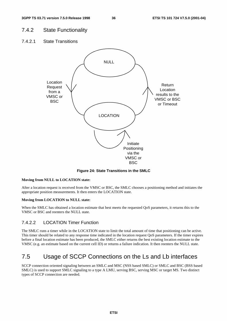
ETSI
ETSI TS 101 724 V7.5.0 (2001-04)363GPP TS 03.71 version 7.5.0 Release 1998
7.4.2 State Functionality
7.4.2.1 State Transitions
LOCATION
NULL
LocationRequestfrom a
VMSC orBSC
ReturnLocation
results to theVMSC or BSC
or Timeout
InitiatePositioning
via theVMSC or
BSC
Figure 24: State Transitions in the SMLC
Moving from NULL to LOCATION state:
After a location request is received from the VMSC or BSC, the SMLC chooses a positioning method and initiates the appropriate position measurements. It then enters the LOCATION state.
Moving from LOCATION to NULL state:
When the SMLC has obtained a location estimate that best meets the requested QoS parameters, it returns this to the VMSC or BSC and reenters the NULL state.
7.4.2.2 LOCATION Timer Function
The SMLC runs a timer while in the LOCATION state to limit the total amount of time that positioning can be active. This timer should be related to any response time indicated in the location request QoS parameters. If the timer expires before a final location estimate has been produced, the SMLC either returns the best existing location estimate to the VMSC (e.g. an estimate based on the current cell ID) or returns a failure indication. It then reenters the NULL state.
7.5 Usage of SCCP Connections on the Ls and Lb interfaces SCCP connection oriented signaling between an SMLC and MSC (NSS based SMLC) or SMLC and BSC (BSS based SMLC) is used to support SMLC signaling to a type A LMU, serving BSC, serving MSC or target MS. Two distinct types of SCCP connection are needed.
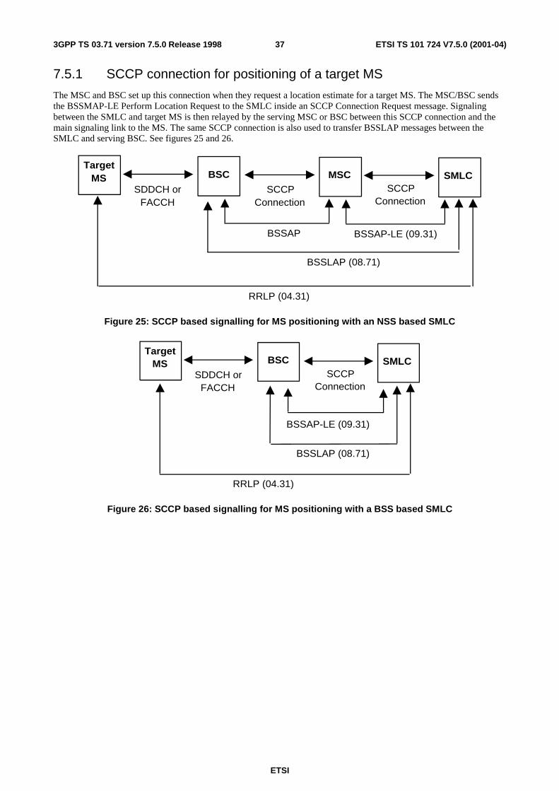
ETSI
ETSI TS 101 724 V7.5.0 (2001-04)373GPP TS 03.71 version 7.5.0 Release 1998
7.5.1 SCCP connection for positioning of a target MS
The MSC and BSC set up this connection when they request a location estimate for a target MS. The MSC/BSC sends the BSSMAP-LE Perform Location Request to the SMLC inside an SCCP Connection Request message. Signaling between the SMLC and target MS is then relayed by the serving MSC or BSC between this SCCP connection and the main signaling link to the MS. The same SCCP connection is also used to transfer BSSLAP messages between the SMLC and serving BSC. See figures 25 and 26.
TargetMS BSC MSC SMLC
SCCPConnection
SCCPConnection
SDDCH orFACCH
BSSLAP (08.71)
RRLP (04.31)
BSSAP-LE (09.31)BSSAP
Figure 25: SCCP based signalling for MS positioning with an NSS based SMLC
TargetMS BSC SMLC
SCCPConnection
SDDCH orFACCH
BSSLAP (08.71)
RRLP (04.31)
BSSAP-LE (09.31)
Figure 26: SCCP based signalling for MS positioning with a BSS based SMLC
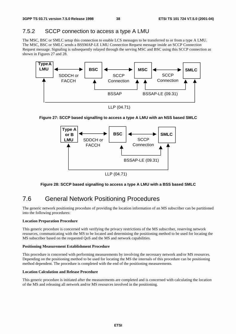
ETSI
ETSI TS 101 724 V7.5.0 (2001-04)383GPP TS 03.71 version 7.5.0 Release 1998
7.5.2 SCCP connection to access a type A LMU
The MSC, BSC or SMLC setup this connection to enable LCS messages to be transferred to or from a type A LMU. The MSC, BSC or SMLC sends a BSSMAP-LE LMU Connection Request message inside an SCCP Connection Request message. Signaling is subsequently relayed through the serving MSC and BSC using this SCCP connection as shown in Figures 27 and 28.
Type ALMU BSC MSC SMLC
SCCPConnection
SCCPConnection
SDDCH orFACCH
LLP (04.71)
BSSAP-LE (09.31)BSSAP
Figure 27: SCCP based signalling to access a type A LMU with an NSS based SMLC
Type Aor BLMU
BSC SMLCSCCP
ConnectionSDDCH or
FACCH
LLP (04.71)
BSSAP-LE (09.31)
Figure 28: SCCP based signalling to access a type A LMU with a BSS based SMLC
7.6 General Network Positioning Procedures The generic network positioning procedure of providing the location information of an MS subscriber can be partitioned into the following procedures:
Location Preparation Procedure
This generic procedure is concerned with verifying the privacy restrictions of the MS subscriber, reserving network resources, communicating with the MS to be located and determining the positioning method to be used for locating the MS subscriber based on the requested QoS and the MS and network capabilities.
Positioning Measurement Establishment Procedure
This procedure is concerned with performing measurements by involving the necessary network and/or MS resources. Depending on the positioning method to be used for locating the MS the internals of this procedure can be positioning method dependent. The procedure is completed with the end of the positioning measurements.
Location Calculation and Release Procedure
This generic procedure is initiated after the measurements are completed and is concerned with calculating the location of the MS and releasing all network and/or MS resources involved in the positioning.
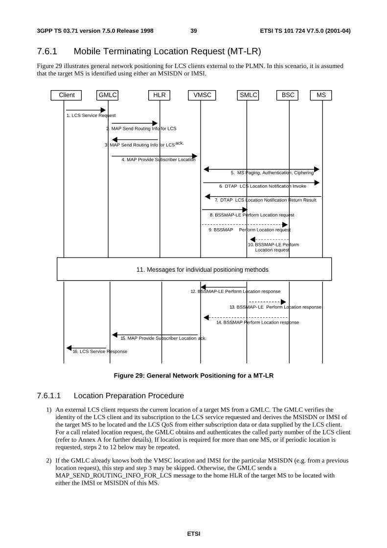
ETSI
ETSI TS 101 724 V7.5.0 (2001-04)393GPP TS 03.71 version 7.5.0 Release 1998
7.6.1 Mobile Terminating Location Request (MT-LR)
Figure 29 illustrates general network positioning for LCS clients external to the PLMN. In this scenario, it is assumed that the target MS is identified using either an MSISDN or IMSI.
12. BSSMAP-LE Perform Location response
MSBSCHLRGMLC SMLCClient VMSC
8. BSSMAP-LE Perform Location request
5. MS Paging, Authentication, Ciphering
16. LCS Service Response
2. MAP Send Routing Info for LCS
1. LCS Service Request
3. MAP Send Routing Info for LCS ack.
4. MAP Provide Subscriber Location
11. Messages for individual positioning methods
15. MAP Provide Subscriber Location ack.
10. BSSMAP-LE PerformLocation request
14. BSSMAP Perform Location response
9. BSSMAP Perform Location request
13. BSSMAP- LE Perform Location response
6. DTAP LCS Location Notification Invoke
7. DTAP LCS Location Notification Return Result
Figure 29: General Network Positioning for a MT-LR
7.6.1.1 Location Preparation Procedure
1) An external LCS client requests the current location of a target MS from a GMLC. The GMLC verifies the identity of the LCS client and its subscription to the LCS service requested and derives the MSISDN or IMSI of the target MS to be located and the LCS QoS from either subscription data or data supplied by the LCS client. For a call related location request, the GMLC obtains and authenticates the called party number of the LCS client (refer to Annex A for further details). If location is required for more than one MS, or if periodic location is requested, steps 2 to 12 below may be repeated.
2) If the GMLC already knows both the VMSC location and IMSI for the particular MSISDN (e.g. from a previous location request), this step and step 3 may be skipped. Otherwise, the GMLC sends a MAP_SEND_ROUTING_INFO_FOR_LCS message to the home HLR of the target MS to be located with either the IMSI or MSISDN of this MS.
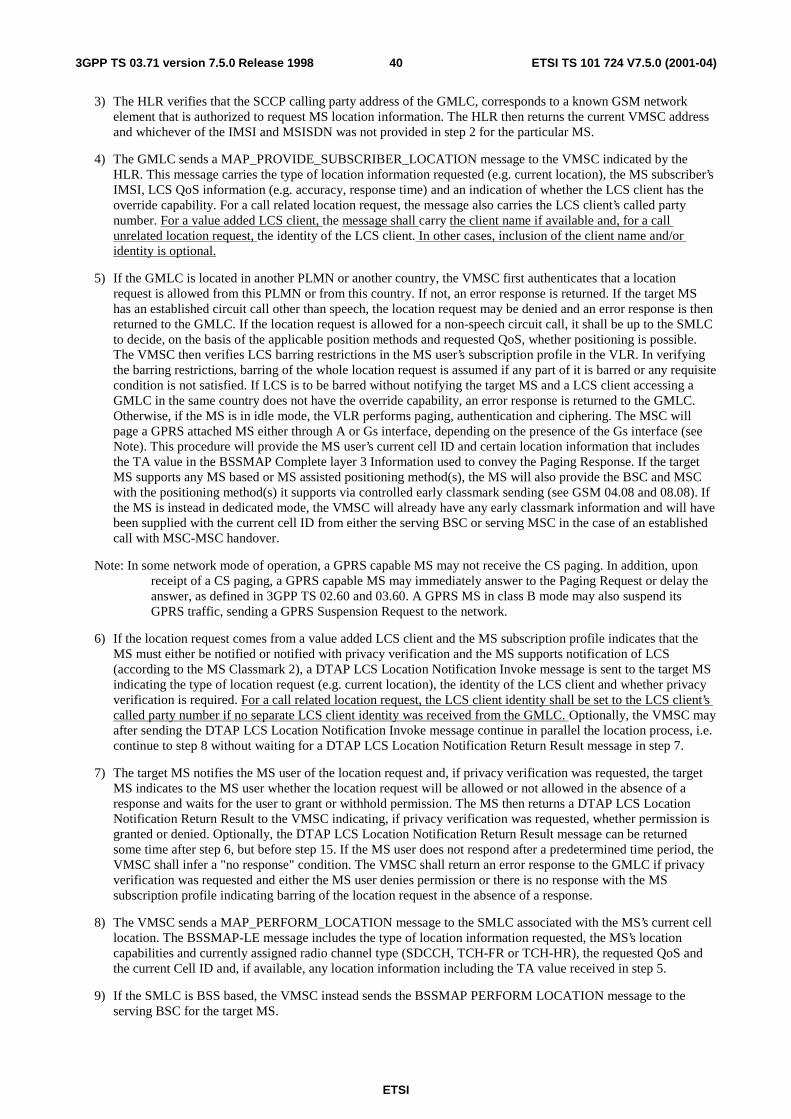
ETSI
ETSI TS 101 724 V7.5.0 (2001-04)403GPP TS 03.71 version 7.5.0 Release 1998
3) The HLR verifies that the SCCP calling party address of the GMLC, corresponds to a known GSM network element that is authorized to request MS location information. The HLR then returns the current VMSC address and whichever of the IMSI and MSISDN was not provided in step 2 for the particular MS.
4) The GMLC sends a MAP_PROVIDE_SUBSCRIBER_LOCATION message to the VMSC indicated by the HLR. This message carries the type of location information requested (e.g. current location), the MS subscriber’s IMSI, LCS QoS information (e.g. accuracy, response time) and an indication of whether the LCS client has the override capability. For a call related location request, the message also carries the LCS client’s called party number. For a value added LCS client, the message shall carry the client name if available and, for a call unrelated location request, the identity of the LCS client. In other cases, inclusion of the client name and/or identity is optional.
5) If the GMLC is located in another PLMN or another country, the VMSC first authenticates that a location request is allowed from this PLMN or from this country. If not, an error response is returned. If the target MS has an established circuit call other than speech, the location request may be denied and an error response is then returned to the GMLC. If the location request is allowed for a non-speech circuit call, it shall be up to the SMLC to decide, on the basis of the applicable position methods and requested QoS, whether positioning is possible. The VMSC then verifies LCS barring restrictions in the MS user’s subscription profile in the VLR. In verifying the barring restrictions, barring of the whole location request is assumed if any part of it is barred or any requisite condition is not satisfied. If LCS is to be barred without notifying the target MS and a LCS client accessing a GMLC in the same country does not have the override capability, an error response is returned to the GMLC. Otherwise, if the MS is in idle mode, the VLR performs paging, authentication and ciphering. The MSC will page a GPRS attached MS either through A or Gs interface, depending on the presence of the Gs interface (see Note). This procedure will provide the MS user’s current cell ID and certain location information that includes the TA value in the BSSMAP Complete layer 3 Information used to convey the Paging Response. If the target MS supports any MS based or MS assisted positioning method(s), the MS will also provide the BSC and MSC with the positioning method(s) it supports via controlled early classmark sending (see GSM 04.08 and 08.08). If the MS is instead in dedicated mode, the VMSC will already have any early classmark information and will have been supplied with the current cell ID from either the serving BSC or serving MSC in the case of an established call with MSC-MSC handover.
Note: In some network mode of operation, a GPRS capable MS may not receive the CS paging. In addition, upon receipt of a CS paging, a GPRS capable MS may immediately answer to the Paging Request or delay the answer, as defined in 3GPP TS 02.60 and 03.60. A GPRS MS in class B mode may also suspend its GPRS traffic, sending a GPRS Suspension Request to the network.
6) If the location request comes from a value added LCS client and the MS subscription profile indicates that the MS must either be notified or notified with privacy verification and the MS supports notification of LCS (according to the MS Classmark 2), a DTAP LCS Location Notification Invoke message is sent to the target MS indicating the type of location request (e.g. current location), the identity of the LCS client and whether privacy verification is required. For a call related location request, the LCS client identity shall be set to the LCS client’s called party number if no separate LCS client identity was received from the GMLC. Optionally, the VMSC may after sending the DTAP LCS Location Notification Invoke message continue in parallel the location process, i.e. continue to step 8 without waiting for a DTAP LCS Location Notification Return Result message in step 7.
7) The target MS notifies the MS user of the location request and, if privacy verification was requested, the target MS indicates to the MS user whether the location request will be allowed or not allowed in the absence of a response and waits for the user to grant or withhold permission. The MS then returns a DTAP LCS Location Notification Return Result to the VMSC indicating, if privacy verification was requested, whether permission is granted or denied. Optionally, the DTAP LCS Location Notification Return Result message can be returned some time after step 6, but before step 15. If the MS user does not respond after a predetermined time period, the VMSC shall infer a "no response" condition. The VMSC shall return an error response to the GMLC if privacy verification was requested and either the MS user denies permission or there is no response with the MS subscription profile indicating barring of the location request in the absence of a response.
8) The VMSC sends a MAP_PERFORM_LOCATION message to the SMLC associated with the MS’s current cell location. The BSSMAP-LE message includes the type of location information requested, the MS’s location capabilities and currently assigned radio channel type (SDCCH, TCH-FR or TCH-HR), the requested QoS and the current Cell ID and, if available, any location information including the TA value received in step 5.
9) If the SMLC is BSS based, the VMSC instead sends the BSSMAP PERFORM LOCATION message to the serving BSC for the target MS.
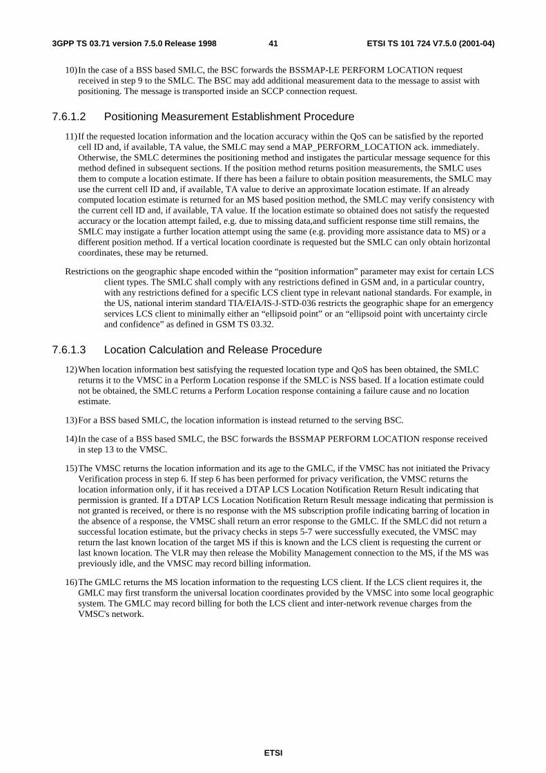
ETSI
ETSI TS 101 724 V7.5.0 (2001-04)413GPP TS 03.71 version 7.5.0 Release 1998
10) In the case of a BSS based SMLC, the BSC forwards the BSSMAP-LE PERFORM LOCATION request received in step 9 to the SMLC. The BSC may add additional measurement data to the message to assist with positioning. The message is transported inside an SCCP connection request.
7.6.1.2 Positioning Measurement Establishment Procedure
11) If the requested location information and the location accuracy within the QoS can be satisfied by the reported cell ID and, if available, TA value, the SMLC may send a MAP_PERFORM_LOCATION ack. immediately. Otherwise, the SMLC determines the positioning method and instigates the particular message sequence for this method defined in subsequent sections. If the position method returns position measurements, the SMLC uses them to compute a location estimate. If there has been a failure to obtain position measurements, the SMLC may use the current cell ID and, if available, TA value to derive an approximate location estimate. If an already computed location estimate is returned for an MS based position method, the SMLC may verify consistency with the current cell ID and, if available, TA value. If the location estimate so obtained does not satisfy the requested accuracy or the location attempt failed, e.g. due to missing data,and sufficient response time still remains, the SMLC may instigate a further location attempt using the same (e.g. providing more assistance data to MS) or a different position method. If a vertical location coordinate is requested but the SMLC can only obtain horizontal coordinates, these may be returned.
Restrictions on the geographic shape encoded within the “position information” parameter may exist for certain LCS client types. The SMLC shall comply with any restrictions defined in GSM and, in a particular country, with any restrictions defined for a specific LCS client type in relevant national standards. For example, in the US, national interim standard TIA/EIA/IS-J-STD-036 restricts the geographic shape for an emergency services LCS client to minimally either an “ellipsoid point” or an “ellipsoid point with uncertainty circle and confidence” as defined in GSM TS 03.32.
7.6.1.3 Location Calculation and Release Procedure
12) When location information best satisfying the requested location type and QoS has been obtained, the SMLC returns it to the VMSC in a Perform Location response if the SMLC is NSS based. If a location estimate could not be obtained, the SMLC returns a Perform Location response containing a failure cause and no location estimate.
13) For a BSS based SMLC, the location information is instead returned to the serving BSC.
14) In the case of a BSS based SMLC, the BSC forwards the BSSMAP PERFORM LOCATION response received in step 13 to the VMSC.
15) The VMSC returns the location information and its age to the GMLC, if the VMSC has not initiated the Privacy Verification process in step 6. If step 6 has been performed for privacy verification, the VMSC returns the location information only, if it has received a DTAP LCS Location Notification Return Result indicating that permission is granted. If a DTAP LCS Location Notification Return Result message indicating that permission is not granted is received, or there is no response with the MS subscription profile indicating barring of location in the absence of a response, the VMSC shall return an error response to the GMLC. If the SMLC did not return a successful location estimate, but the privacy checks in steps 5-7 were successfully executed, the VMSC may return the last known location of the target MS if this is known and the LCS client is requesting the current or last known location. The VLR may then release the Mobility Management connection to the MS, if the MS was previously idle, and the VMSC may record billing information.
16) The GMLC returns the MS location information to the requesting LCS client. If the LCS client requires it, the GMLC may first transform the universal location coordinates provided by the VMSC into some local geographic system. The GMLC may record billing for both the LCS client and inter-network revenue charges from the VMSC's network.
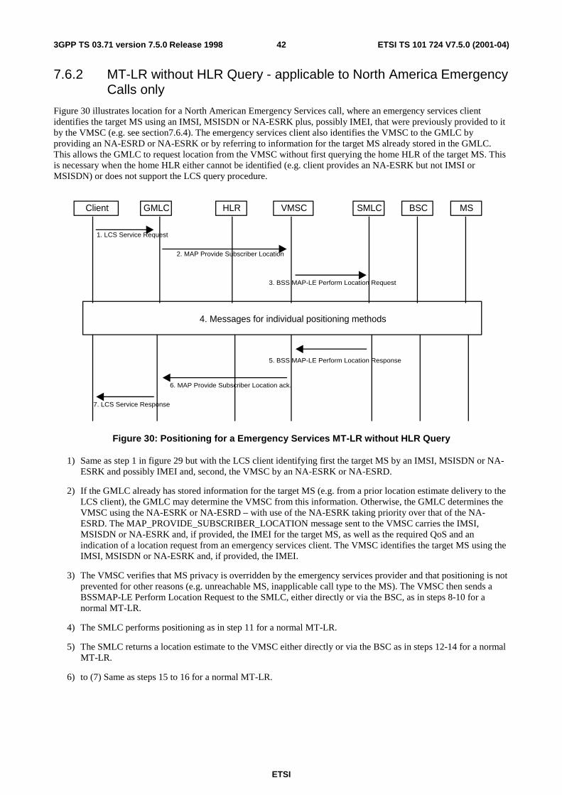
ETSI
ETSI TS 101 724 V7.5.0 (2001-04)423GPP TS 03.71 version 7.5.0 Release 1998
7.6.2 MT-LR without HLR Query - applicable to North America Emergency Calls only
Figure 30 illustrates location for a North American Emergency Services call, where an emergency services client identifies the target MS using an IMSI, MSISDN or NA-ESRK plus, possibly IMEI, that were previously provided to it by the VMSC (e.g. see section7.6.4). The emergency services client also identifies the VMSC to the GMLC by providing an NA-ESRD or NA-ESRK or by referring to information for the target MS already stored in the GMLC. This allows the GMLC to request location from the VMSC without first querying the home HLR of the target MS. This is necessary when the home HLR either cannot be identified (e.g. client provides an NA-ESRK but not IMSI or MSISDN) or does not support the LCS query procedure.
MSBSCHLRGMLC SMLCClient VMSC
3. BSS MAP-LE Perform Location Request
7. LCS Service Response
1. LCS Service Request
2. MAP Provide Subscriber Location
4. Messages for individual positioning methods
6. MAP Provide Subscriber Location ack.
5. BSS MAP-LE Perform Location Response
Figure 30: Positioning for a Emergency Services MT-LR without HLR Query
1) Same as step 1 in figure 29 but with the LCS client identifying first the target MS by an IMSI, MSISDN or NA-ESRK and possibly IMEI and, second, the VMSC by an NA-ESRK or NA-ESRD.
2) If the GMLC already has stored information for the target MS (e.g. from a prior location estimate delivery to the LCS client), the GMLC may determine the VMSC from this information. Otherwise, the GMLC determines the VMSC using the NA-ESRK or NA-ESRD – with use of the NA-ESRK taking priority over that of the NA-ESRD. The MAP_PROVIDE_SUBSCRIBER_LOCATION message sent to the VMSC carries the IMSI, MSISDN or NA-ESRK and, if provided, the IMEI for the target MS, as well as the required QoS and an indication of a location request from an emergency services client. The VMSC identifies the target MS using the IMSI, MSISDN or NA-ESRK and, if provided, the IMEI.
3) The VMSC verifies that MS privacy is overridden by the emergency services provider and that positioning is not prevented for other reasons (e.g. unreachable MS, inapplicable call type to the MS). The VMSC then sends a BSSMAP-LE Perform Location Request to the SMLC, either directly or via the BSC, as in steps 8-10 for a normal MT-LR.
4) The SMLC performs positioning as in step 11 for a normal MT-LR.
5) The SMLC returns a location estimate to the VMSC either directly or via the BSC as in steps 12-14 for a normal MT-LR.
6) to (7) Same as steps 15 to 16 for a normal MT-LR.
ETSI
ETSI TS 101 724 V7.5.0 (2001-04)433GPP TS 03.71 version 7.5.0 Release 1998
7.6.3 MT-LR for a previously obtained location estimate
Every time the location estimate of a target MS subscriber is returned by the SMLC to the VMSC, the VMSC may store the location estimate together with a time stamp in the subscriber’s VLR record.
The time stamp is the time at which the location estimate is stored at the VLR i.e. after the SMLC returns the location estimate to the VMSC. The time stamp indicates the ’age’ of the location estimate.
7.6.3.1 Initial Location
In the context of an originating emergency call the location estimate and the associated time stamp at the commencement of the call set-up is referred to as ’initial location’.
7.6.3.2 Current Location
After a location attempt has successfully delivered a location estimate and its assocoiated time stamp, the location estimate and time stamp is referred to as the ’current location’ at that point in time.
7.6.3.3 Last known Location
The current location estimate and its associated time stamp are stored in MSC/VLR and until replaced by a later location estimate and a new time stamp is referred to as the ’last known location’. The last known location may be distinct from the initial location – i.e. more recent.
7.6.3.4 Security and Privacy
The handling of security and privacy of the target MS with regard to returning the last known or initial location estimate of the target MS shall be the same as when the target MS is reachable for positioning. (i.e. the requesting LCS client is authorized and the privacy of the target MS is secured before the VMSC check the VLR status of the target MS (i.e. whether the MS is marked as attached or detached in the VLR).
7.6.3.5 Failing to locate the target MS
In case of a 'Detached' or 'Not Reachable' target MS, the last known location and a time stamp stored at the VLR, may be returned to a LCS client requesting location information if the LCS client specifically requested the current or last known location. This does not apply to a value added LCS client where the target MS subscribes to notification of the location request: if the notification cannot be performed, the VMSC shall reject the location request.
NOTE: Due to CAMEL, the MSC/VLR may already be storing other location information parameters like location number, cell id, location area identity and VLR number in the subscriber's VLR record.
When a request for location information is received at the VMSC, the request shall indicate whether the 'last known location of the target MS' should be returned in case of a 'detached' or 'not reachable' target MS.
If the VLR has a valid copy of the subscriber's permanent data and the target MS's privacy settings are such that positioning is allowed, then the following cases can occur.
7.6.3.5.1 Target MS is ’Not Reachable’
If the target MS is marked as 'attached' in the VLR, the VMSC orders paging of the target MS. If paging fails, due to target MS being 'not reachable' then VMSC shall check whether the LCS client has requested 'last known location' in case of 'not reachable' target MS.
If such a request exists and notification to the target MS does not apply for a value added LCS client, the VMSC shall include the last known location together with the time stamp available in its response to the request for location information.
An indicator of 'last known location' returned shall be marked at the CDR at VMSC.
ETSI
ETSI TS 101 724 V7.5.0 (2001-04)443GPP TS 03.71 version 7.5.0 Release 1998
7.6.3.5.2 Target MS is ’Detached’
If the target MS is marked as ’detached’ in the VLR, the VMSC shall check whether the LCS client has requested ’last known location’ in case of ’detached’ target MS.
If such a request exists and notification to the target MS does not apply for a value added LCS client, the VMSC includes the ’last known location’ together with the time stamp available in its response to the request for location information.
An indicator of ’last known location’ returned shall be marked at the CDR at VMSC.
7.6.3.5.3 Target MS is Reachable but Positioning Fails
If the target MS is reachable (e.g. paging succeeds), but the VMSC is unable to obtain a current location estimate, the VMSC shall check whether the LCS client has requested ’last known location’.
If such a request exists and notification to the target MS either does not apply or was successfully executed for a value added LCS client, the VMSC includes the ’last known location’ together with the time stamp available in its response to the request for location information.
An indicator of ’last known location’ returned shall be marked at the CDR at VMSC.
7.6.3.5.4 Target MS is ’Purged’
If the target MS is marked as ’Purged’ in HLR, then an indication ’Absent Subscriber’ is returned to the GMLC.
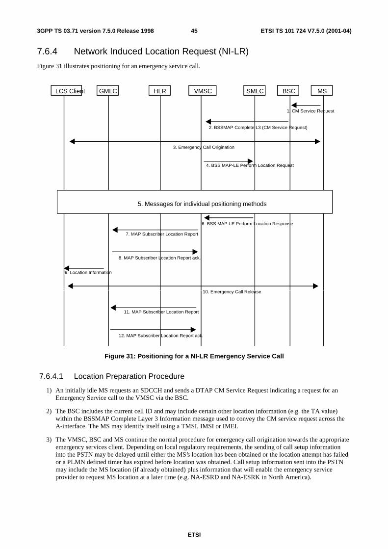
ETSI
ETSI TS 101 724 V7.5.0 (2001-04)453GPP TS 03.71 version 7.5.0 Release 1998
7.6.4 Network Induced Location Request (NI-LR)
Figure 31 illustrates positioning for an emergency service call.
MSBSCHLRGMLC SMLCLCS Client VMSC
4. BSS MAP-LE Perform Location Request
6. BSS MAP-LE Perform Location Response
2. BSSMAP Complete L3 (CM Service Request)
3. Emergency Call Origination
1. CM Service Request
8. MAP Subscriber Location Report ack.
7. MAP Subscriber Location Report
9. Location Information
5. Messages for individual positioning methods
12. MAP Subscriber Location Report ack.
11. MAP Subscriber Location Report
10. Emergency Call Release
Figure 31: Positioning for a NI-LR Emergency Service Call
7.6.4.1 Location Preparation Procedure
1) An initially idle MS requests an SDCCH and sends a DTAP CM Service Request indicating a request for an Emergency Service call to the VMSC via the BSC.
2) The BSC includes the current cell ID and may include certain other location information (e.g. the TA value) within the BSSMAP Complete Layer 3 Information message used to convey the CM service request across the A-interface. The MS may identify itself using a TMSI, IMSI or IMEI.
3) The VMSC, BSC and MS continue the normal procedure for emergency call origination towards the appropriate emergency services client. Depending on local regulatory requirements, the sending of call setup information into the PSTN may be delayed until either the MS’s location has been obtained or the location attempt has failed or a PLMN defined timer has expired before location was obtained. Call setup information sent into the PSTN may include the MS location (if already obtained) plus information that will enable the emergency service provider to request MS location at a later time (e.g. NA-ESRD and NA-ESRK in North America).
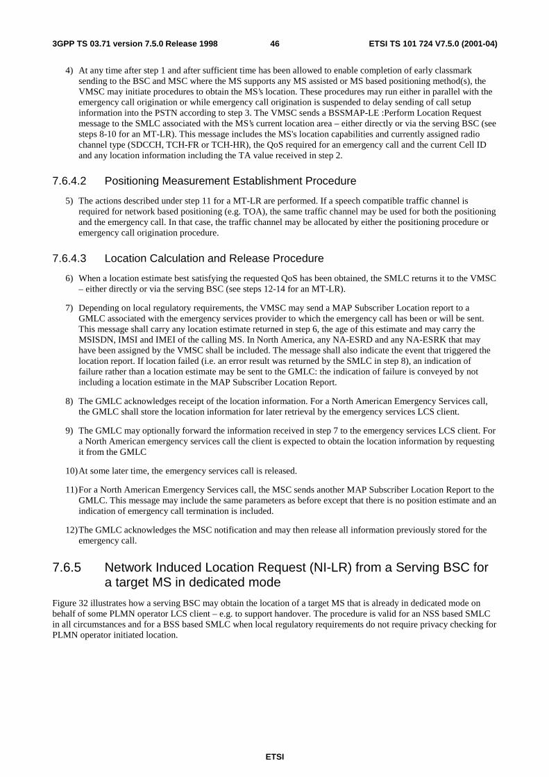
ETSI
ETSI TS 101 724 V7.5.0 (2001-04)463GPP TS 03.71 version 7.5.0 Release 1998
4) At any time after step 1 and after sufficient time has been allowed to enable completion of early classmark sending to the BSC and MSC where the MS supports any MS assisted or MS based positioning method(s), the VMSC may initiate procedures to obtain the MS’s location. These procedures may run either in parallel with the emergency call origination or while emergency call origination is suspended to delay sending of call setup information into the PSTN according to step 3. The VMSC sends a BSSMAP-LE :Perform Location Request message to the SMLC associated with the MS’s current location area – either directly or via the serving BSC (see steps 8-10 for an MT-LR). This message includes the MS's location capabilities and currently assigned radio channel type (SDCCH, TCH-FR or TCH-HR), the QoS required for an emergency call and the current Cell ID and any location information including the TA value received in step 2.
7.6.4.2 Positioning Measurement Establishment Procedure
5) The actions described under step 11 for a MT-LR are performed. If a speech compatible traffic channel is required for network based positioning (e.g. TOA), the same traffic channel may be used for both the positioning and the emergency call. In that case, the traffic channel may be allocated by either the positioning procedure or emergency call origination procedure.
7.6.4.3 Location Calculation and Release Procedure
6) When a location estimate best satisfying the requested QoS has been obtained, the SMLC returns it to the VMSC – either directly or via the serving BSC (see steps 12-14 for an MT-LR).
7) Depending on local regulatory requirements, the VMSC may send a MAP Subscriber Location report to a GMLC associated with the emergency services provider to which the emergency call has been or will be sent. This message shall carry any location estimate returned in step 6, the age of this estimate and may carry the MSISDN, IMSI and IMEI of the calling MS. In North America, any NA-ESRD and any NA-ESRK that may have been assigned by the VMSC shall be included. The message shall also indicate the event that triggered the location report. If location failed (i.e. an error result was returned by the SMLC in step 8), an indication of failure rather than a location estimate may be sent to the GMLC: the indication of failure is conveyed by not including a location estimate in the MAP Subscriber Location Report.
8) The GMLC acknowledges receipt of the location information. For a North American Emergency Services call, the GMLC shall store the location information for later retrieval by the emergency services LCS client.
9) The GMLC may optionally forward the information received in step 7 to the emergency services LCS client. For a North American emergency services call the client is expected to obtain the location information by requesting it from the GMLC
10) At some later time, the emergency services call is released.
11) For a North American Emergency Services call, the MSC sends another MAP Subscriber Location Report to the GMLC. This message may include the same parameters as before except that there is no position estimate and an indication of emergency call termination is included.
12) The GMLC acknowledges the MSC notification and may then release all information previously stored for the emergency call.
7.6.5 Network Induced Location Request (NI-LR) from a Serving BSC for a target MS in dedicated mode
Figure 32 illustrates how a serving BSC may obtain the location of a target MS that is already in dedicated mode on behalf of some PLMN operator LCS client – e.g. to support handover. The procedure is valid for an NSS based SMLC in all circumstances and for a BSS based SMLC when local regulatory requirements do not require privacy checking for PLMN operator initiated location.
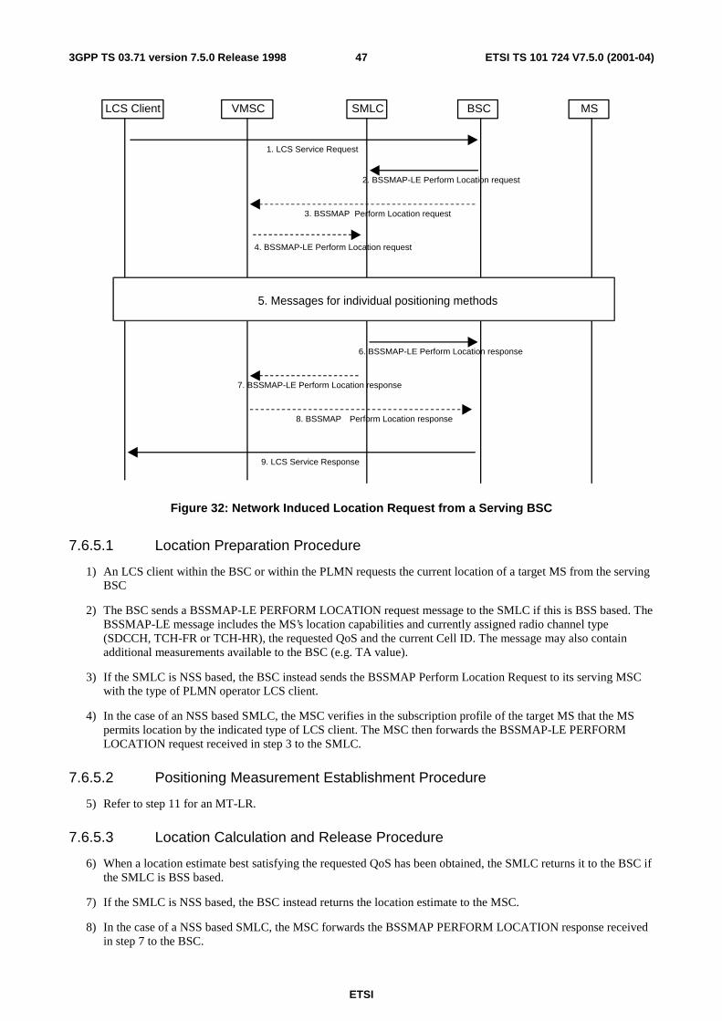
ETSI
ETSI TS 101 724 V7.5.0 (2001-04)473GPP TS 03.71 version 7.5.0 Release 1998
MSBSCSMLCLCS Client VMSC
2. BSSMAP-LE Perform Location request
5. Messages for individual positioning methods
1. LCS Service Request
4. BSSMAP-LE Perform Location request
6. BSSMAP-LE Perform Location response
8. BSSMAP Perform Location response
9. LCS Service Response
3. BSSMAP Perform Location request
7. BSSMAP-LE Perform Location response
Figure 32: Network Induced Location Request from a Serving BSC
7.6.5.1 Location Preparation Procedure
1) An LCS client within the BSC or within the PLMN requests the current location of a target MS from the serving BSC
2) The BSC sends a BSSMAP-LE PERFORM LOCATION request message to the SMLC if this is BSS based. The BSSMAP-LE message includes the MS’s location capabilities and currently assigned radio channel type (SDCCH, TCH-FR or TCH-HR), the requested QoS and the current Cell ID. The message may also contain additional measurements available to the BSC (e.g. TA value).
3) If the SMLC is NSS based, the BSC instead sends the BSSMAP Perform Location Request to its serving MSC with the type of PLMN operator LCS client.
4) In the case of an NSS based SMLC, the MSC verifies in the subscription profile of the target MS that the MS permits location by the indicated type of LCS client. The MSC then forwards the BSSMAP-LE PERFORM LOCATION request received in step 3 to the SMLC.
7.6.5.2 Positioning Measurement Establishment Procedure
5) Refer to step 11 for an MT-LR.
7.6.5.3 Location Calculation and Release Procedure
6) When a location estimate best satisfying the requested QoS has been obtained, the SMLC returns it to the BSC if the SMLC is BSS based.
7) If the SMLC is NSS based, the BSC instead returns the location estimate to the MSC.
8) In the case of a NSS based SMLC, the MSC forwards the BSSMAP PERFORM LOCATION response received in step 7 to the BSC.
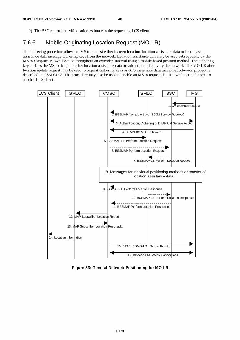
ETSI
ETSI TS 101 724 V7.5.0 (2001-04)483GPP TS 03.71 version 7.5.0 Release 1998
9) The BSC returns the MS location estimate to the requesting LCS client.
7.6.6 Mobile Originating Location Request (MO-LR)
The following procedure allows an MS to request either its own location, location assistance data or broadcast assistance data message ciphering keys from the network. Location assistance data may be used subsequently by the MS to compute its own location throughout an extended interval using a mobile based position method. The ciphering key enables the MS to decipher other location assistance data broadcast periodically by the network. The MO-LR after location update request may be used to request ciphering keys or GPS assistance data using the follow-on procedure described in GSM 04.08. The procedure may also be used to enable an MS to request that its own location be sent to another LCS client.
MSBSCSMLCVMSC
5. BSSMAP-LE Perform Location Request
15. DTAP LCS MO-LR Return Result
4. DTAP LCS MO-LR Invoke
3. Authentication, Ciphering or DTAP CM Service Accept
9.BSSMAP-LE Perform Location Response.
8. Messages for individual positioning methods or transfer oflocation assistance data
16. Release CM, MM, RR Connections
2. BSSMAP Complete Layer 3 (CM Service Request)
1. CM Service Request
6. BSSMAP Perform Location Request
7. BSSMAP-LE Perform Location Request
10. BSSMAP-LE Perform Location Response
11. BSSMAP Perform Location Response
GMLCLCS Client
12. MAP Subscriber Location Report
13. MAP Subscriber Location Report ack.
14. Location Information
Figure 33: General Network Positioning for MO-LR

ETSI
ETSI TS 101 724 V7.5.0 (2001-04)493GPP TS 03.71 version 7.5.0 Release 1998
7.6.6.1 Location Preparation Procedure
1) If the MS is in idle mode, the MS requests an SDCCH and sends a DTAP CM service request indicating a request for call independent supplementary services to the BSC.
2) The BSC includes the current cell ID and TA value within the BSSMAP Complete Layer 3 Information message used to convey the CM service request across the A-interface. If the MS is instead in dedicated mode, the MS sends a DTAP CM Service Request on the already established SACCH: the VMSC will then already have been supplied with the current cell ID from either the serving BSC or serving MSC in the case of an established call with MSC-MSC handover.
3) The VMSC instigates authentication and ciphering if the MS was in idle mode or returns a DTAP CM Service Accept if the MS was in dedicated mode. If the target MS supports any MS based or MS assisted positioning method(s), the MS will provide the BSC and MSC with the positioning method(s) it supports via controlled early classmark sending (see GSM 04.08 and 08.08).
4) The MS sends a DTAP LCS MO-LR invoke to the VMSC. If the MS is requesting its own location or that its own location be sent to another LCS client, this message carries LCS QoS information (e.g. accuracy, response time). If the MS is requesting that its location be sent to another LCS client, the message shall include the identity of the LCS client and may include the address of the GMLC through which the LCS client should be accessed. If a GMLC address is not included, the VMSC may assign its own GMLC address and may verify that the identified LCS client is supported by this GMLC. If a GMLC address is not available for this case, the VMSC shall reject the location request. If the MS is instead requesting location assistance data or ciphering keys, the message specifies the type of assistance data or deciphering keys and the positioning method for which the assistance data or deciphering applies. The VMSC verifies in the MS’s subscription profile that the MS has permission to request its own location, request that its location be sent to another LCS client or request location assistance data or deciphering keys (whichever applies). If the MS is requesting positioning and has an established call, the VMSC may reject the request for certain non-speech call types.
5) The VMSC sends a BSSMAP-LE PERFORM LOCATION request message to the SMLC associated with the MS’s current cell location if the SMLC is NSS based. This message is transported using SCCP connection oriented signaling inside an SCCP Connection Request message The BSSMAP-LE message indicates whether a location estimate or location assistance data is requested and includes the MS’s location capabilities and current cell ID. If the MS’s location is requested, the message also includes the currently assigned radio channel type (SDCCH, TCH-FR or TCH-HR), the requested QoS and, if available and any location measurement information including the TA value received from the BSC in step 2. If location assistance data is instead requested, the message carries the requested types of location assistance data.
6) If the SMLC is BSS based, the VMSC instead sends the BSSMAP PERFORM LOCATION message to the serving BSC for the target MS.
7) In the case of a BSS based SMLC, the BSC forwards the BSSMAP-LE PERFORM LOCATION request received in step 6 to the SMLC. If the MS’s location is requested, the BSC may add additional measurement data to the message to assist with positioning. The message is transported inside an SCCP connection request.
7.6.6.2 Positioning Measurement Establishment Procedure
8) If the MS is requesting its own location, the actions described under step 10 for a MT-LR are performed. If the MS is instead requesting location assistance data, the SMLC transfers this data to the MS as described in subsequent sections. The SMLC determines the exact location assistance data to transfer according to the type of data specified by the MS, the MS location capabilities and the current cell ID.
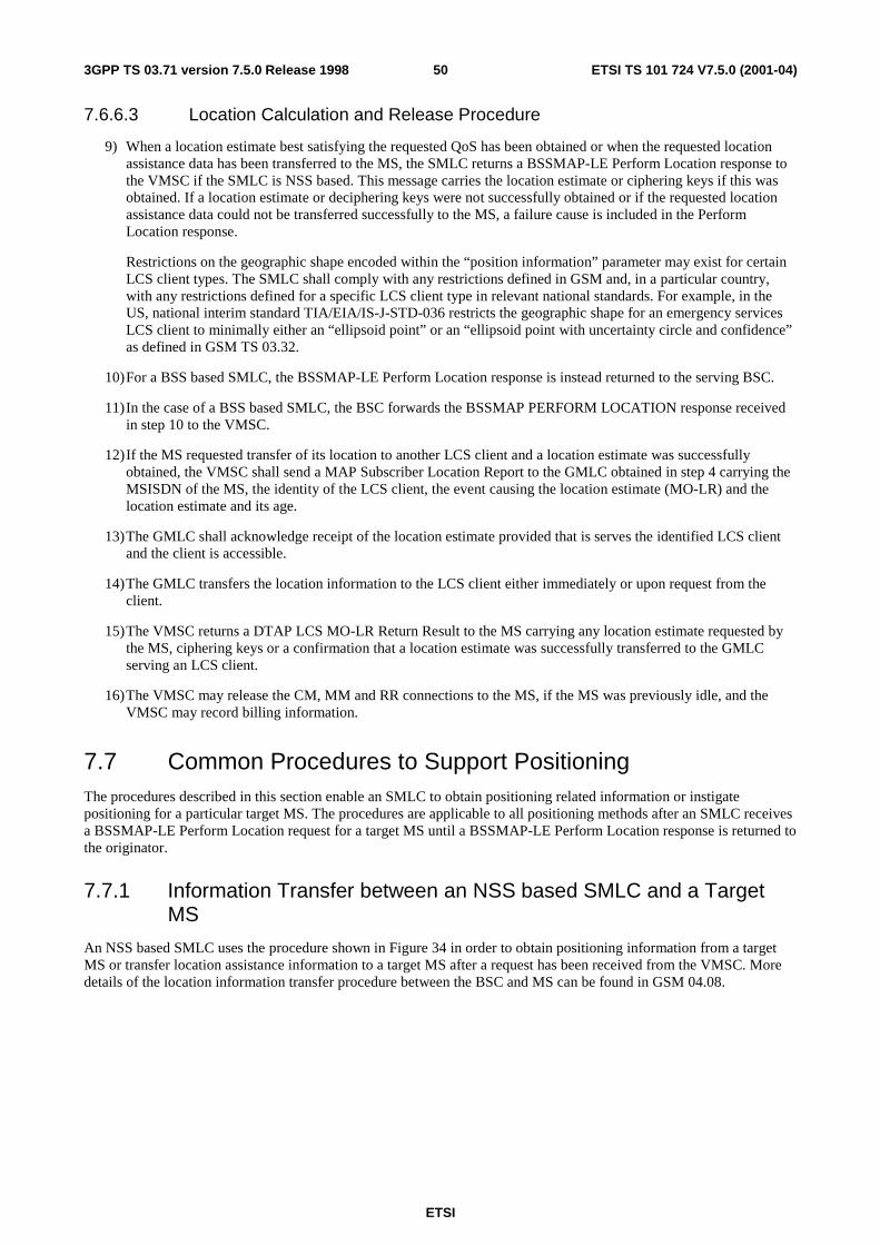
ETSI
ETSI TS 101 724 V7.5.0 (2001-04)503GPP TS 03.71 version 7.5.0 Release 1998
7.6.6.3 Location Calculation and Release Procedure
9) When a location estimate best satisfying the requested QoS has been obtained or when the requested location assistance data has been transferred to the MS, the SMLC returns a BSSMAP-LE Perform Location response to the VMSC if the SMLC is NSS based. This message carries the location estimate or ciphering keys if this was obtained. If a location estimate or deciphering keys were not successfully obtained or if the requested location assistance data could not be transferred successfully to the MS, a failure cause is included in the Perform Location response.
Restrictions on the geographic shape encoded within the “position information” parameter may exist for certain LCS client types. The SMLC shall comply with any restrictions defined in GSM and, in a particular country, with any restrictions defined for a specific LCS client type in relevant national standards. For example, in the US, national interim standard TIA/EIA/IS-J-STD-036 restricts the geographic shape for an emergency services LCS client to minimally either an “ellipsoid point” or an “ellipsoid point with uncertainty circle and confidence” as defined in GSM TS 03.32.
10) For a BSS based SMLC, the BSSMAP-LE Perform Location response is instead returned to the serving BSC.
11) In the case of a BSS based SMLC, the BSC forwards the BSSMAP PERFORM LOCATION response received in step 10 to the VMSC.
12) If the MS requested transfer of its location to another LCS client and a location estimate was successfully obtained, the VMSC shall send a MAP Subscriber Location Report to the GMLC obtained in step 4 carrying the MSISDN of the MS, the identity of the LCS client, the event causing the location estimate (MO-LR) and the location estimate and its age.
13) The GMLC shall acknowledge receipt of the location estimate provided that is serves the identified LCS client and the client is accessible.
14) The GMLC transfers the location information to the LCS client either immediately or upon request from the client.
15) The VMSC returns a DTAP LCS MO-LR Return Result to the MS carrying any location estimate requested by the MS, ciphering keys or a confirmation that a location estimate was successfully transferred to the GMLC serving an LCS client.
16) The VMSC may release the CM, MM and RR connections to the MS, if the MS was previously idle, and the VMSC may record billing information.
7.7 Common Procedures to Support Positioning The procedures described in this section enable an SMLC to obtain positioning related information or instigate positioning for a particular target MS. The procedures are applicable to all positioning methods after an SMLC receives a BSSMAP-LE Perform Location request for a target MS until a BSSMAP-LE Perform Location response is returned to the originator.
7.7.1 Information Transfer between an NSS based SMLC and a Target MS
An NSS based SMLC uses the procedure shown in Figure 34 in order to obtain positioning information from a target MS or transfer location assistance information to a target MS after a request has been received from the VMSC. More details of the location information transfer procedure between the BSC and MS can be found in GSM 04.08.
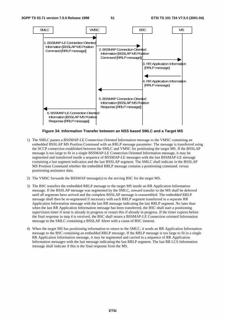
ETSI
ETSI TS 101 724 V7.5.0 (2001-04)513GPP TS 03.71 version 7.5.0 Release 1998
SMLC VMSC BSC MS
1. BSSMAP-LE Connection Oriented Information [BSSLAP MS Position Command [RRLP message]] 2. BSSMAP Connection Oriented
Information [BSSLAP MS Position Command [RRLP message]]
3. RR Application Information [RRLP message]
4. RR Application Information [RRLP message]
5. BSSMAP Connection Oriented Information [BSSLAP MS Position Response [RRLP message]]
6. BSSMAP-LE Connection Oriented Information [BSSLAP MS Position Response [RRLP message]]
Figure 34: Information Transfer between an NSS based SMLC and a Target MS
1) The SMLC passes a BSSMAP-LE Connection Oriented Information message to the VMSC containing an embedded BSSLAP MS Position Command with an RRLP message parameter. The message is transferred using the SCCP connection established between the SMLC and VMSC for positioning the target MS. If the BSSLAP message is too large to fit in a single BSSMAP-LE Connection Oriented Information message, it may be segmented and transferred inside a sequence of BSSMAP-LE messages with the last BSSMAP-LE message containing a last segment indication and the last BSSLAP segment. The SMLC shall indicate in the BSSLAP MS Position Command whether the embedded RRLP message contains a positioning command. versus positioning assistance data.
2) The VMSC forwards the BSSMAP message(s) to the serving BSC for the target MS.
3) The BSC transfers the embedded RRLP message to the target MS inside an RR Application Information message. If the BSSLAP message was segmented by the SMLC, onward transfer to the MS shall be deferred until all segments have arrived and the complete BSSLAP message is reassembled. The embedded RRLP message shall then be re-segmented if necessary with each RRLP segment transferred in a separate RR Application Information message with the last RR message indicating the last RRLP segment. No later than when the last RR Application Information message has been transferred, the BSC shall start a positioning supervision timer if none is already in progress or restart this if already in progress. If the timer expires before the final response in step 4 is received, the BSC shall return a BSSMAP-LE Connection oriented Information message to the SMLC containing a BSSLAP Abort with a cause of BSC timeout.
4) When the target MS has positioning information to return to the SMLC, it sends an RR Application Information message to the BSC containing an embedded RRLP message. If the RRLP message is too large to fit in a single RR Application Information message, it may be segmented and carried in a sequence of RR Application Information messages with the last message indicating the last RRLP segment. The last RR LCS Information message shall indicate if this is the final response from the MS.
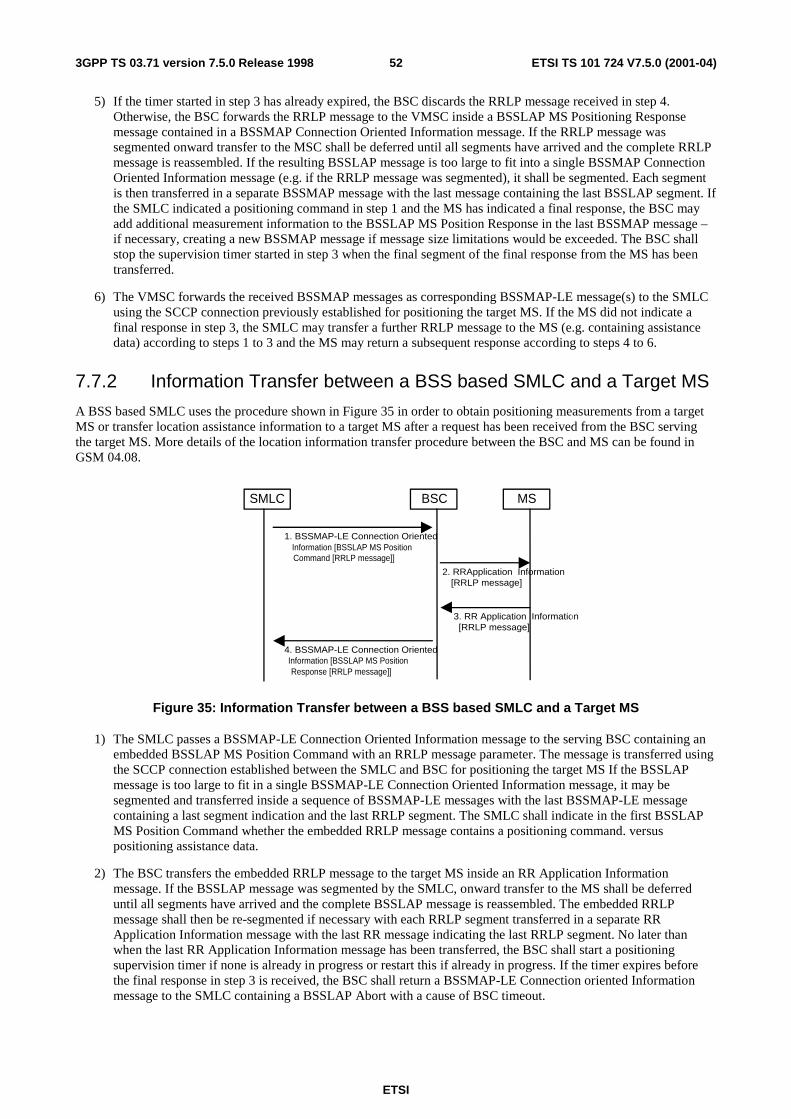
ETSI
ETSI TS 101 724 V7.5.0 (2001-04)523GPP TS 03.71 version 7.5.0 Release 1998
5) If the timer started in step 3 has already expired, the BSC discards the RRLP message received in step 4. Otherwise, the BSC forwards the RRLP message to the VMSC inside a BSSLAP MS Positioning Response message contained in a BSSMAP Connection Oriented Information message. If the RRLP message was segmented onward transfer to the MSC shall be deferred until all segments have arrived and the complete RRLP message is reassembled. If the resulting BSSLAP message is too large to fit into a single BSSMAP Connection Oriented Information message (e.g. if the RRLP message was segmented), it shall be segmented. Each segment is then transferred in a separate BSSMAP message with the last message containing the last BSSLAP segment. If the SMLC indicated a positioning command in step 1 and the MS has indicated a final response, the BSC may add additional measurement information to the BSSLAP MS Position Response in the last BSSMAP message – if necessary, creating a new BSSMAP message if message size limitations would be exceeded. The BSC shall stop the supervision timer started in step 3 when the final segment of the final response from the MS has been transferred.
6) The VMSC forwards the received BSSMAP messages as corresponding BSSMAP-LE message(s) to the SMLC using the SCCP connection previously established for positioning the target MS. If the MS did not indicate a final response in step 3, the SMLC may transfer a further RRLP message to the MS (e.g. containing assistance data) according to steps 1 to 3 and the MS may return a subsequent response according to steps 4 to 6.
7.7.2 Information Transfer between a BSS based SMLC and a Target MS
A BSS based SMLC uses the procedure shown in Figure 35 in order to obtain positioning measurements from a target MS or transfer location assistance information to a target MS after a request has been received from the BSC serving the target MS. More details of the location information transfer procedure between the BSC and MS can be found in GSM 04.08.
1. BSSMAP-LE Connection OrientedInformation [BSSLAP MS PositionCommand [RRLP message]]
4. BSSMAP-LE Connection Oriented
Response [RRLP message]]
MSBSCSMLC
2. RRApplication Information[RRLP message]
3. RR Application Information[RRLP message]
Information [BSSLAP MS Position
Figure 35: Information Transfer between a BSS based SMLC and a Target MS
1) The SMLC passes a BSSMAP-LE Connection Oriented Information message to the serving BSC containing an embedded BSSLAP MS Position Command with an RRLP message parameter. The message is transferred using the SCCP connection established between the SMLC and BSC for positioning the target MS If the BSSLAP message is too large to fit in a single BSSMAP-LE Connection Oriented Information message, it may be segmented and transferred inside a sequence of BSSMAP-LE messages with the last BSSMAP-LE message containing a last segment indication and the last RRLP segment. The SMLC shall indicate in the first BSSLAP MS Position Command whether the embedded RRLP message contains a positioning command. versus positioning assistance data.
2) The BSC transfers the embedded RRLP message to the target MS inside an RR Application Information message. If the BSSLAP message was segmented by the SMLC, onward transfer to the MS shall be deferred until all segments have arrived and the complete BSSLAP message is reassembled. The embedded RRLP message shall then be re-segmented if necessary with each RRLP segment transferred in a separate RR Application Information message with the last RR message indicating the last RRLP segment. No later than when the last RR Application Information message has been transferred, the BSC shall start a positioning supervision timer if none is already in progress or restart this if already in progress. If the timer expires before the final response in step 3 is received, the BSC shall return a BSSMAP-LE Connection oriented Information message to the SMLC containing a BSSLAP Abort with a cause of BSC timeout.
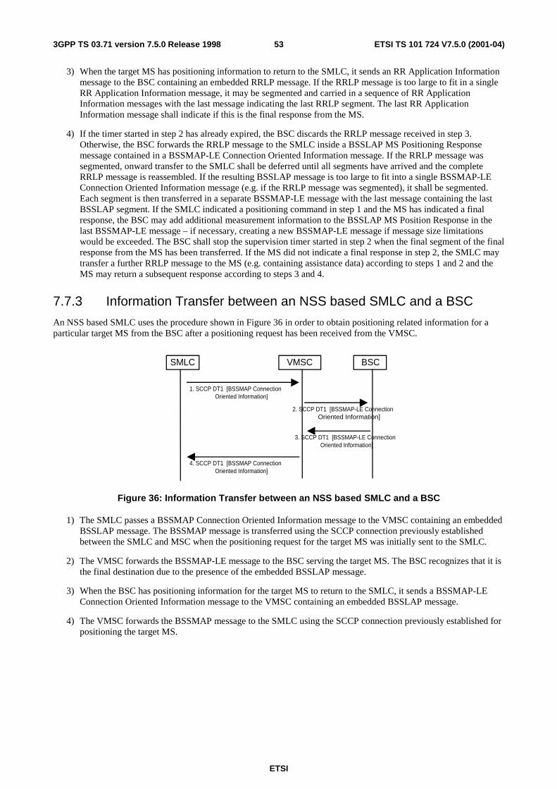
ETSI
ETSI TS 101 724 V7.5.0 (2001-04)533GPP TS 03.71 version 7.5.0 Release 1998
3) When the target MS has positioning information to return to the SMLC, it sends an RR Application Information message to the BSC containing an embedded RRLP message. If the RRLP message is too large to fit in a single RR Application Information message, it may be segmented and carried in a sequence of RR Application Information messages with the last message indicating the last RRLP segment. The last RR Application Information message shall indicate if this is the final response from the MS.
4) If the timer started in step 2 has already expired, the BSC discards the RRLP message received in step 3. Otherwise, the BSC forwards the RRLP message to the SMLC inside a BSSLAP MS Positioning Response message contained in a BSSMAP-LE Connection Oriented Information message. If the RRLP message was segmented, onward transfer to the SMLC shall be deferred until all segments have arrived and the complete RRLP message is reassembled. If the resulting BSSLAP message is too large to fit into a single BSSMAP-LE Connection Oriented Information message (e.g. if the RRLP message was segmented), it shall be segmented. Each segment is then transferred in a separate BSSMAP-LE message with the last message containing the last BSSLAP segment. If the SMLC indicated a positioning command in step 1 and the MS has indicated a final response, the BSC may add additional measurement information to the BSSLAP MS Position Response in the last BSSMAP-LE message – if necessary, creating a new BSSMAP-LE message if message size limitations would be exceeded. The BSC shall stop the supervision timer started in step 2 when the final segment of the final response from the MS has been transferred. If the MS did not indicate a final response in step 2, the SMLC may transfer a further RRLP message to the MS (e.g. containing assistance data) according to steps 1 and 2 and the MS may return a subsequent response according to steps 3 and 4.
7.7.3 Information Transfer between an NSS based SMLC and a BSC
An NSS based SMLC uses the procedure shown in Figure 36 in order to obtain positioning related information for a particular target MS from the BSC after a positioning request has been received from the VMSC.
1. SCCP DT1 [BSSMAP ConnectionOriented Information]
4. SCCP DT1 [BSSMAP ConnectionOriented Information]
BSCSMLC VMSC
2. SCCP DT1 [BSSMAP-LE ConnectionOriented Information]
3. SCCP DT1 [BSSMAP-LE ConnectionOriented Information]
Figure 36: Information Transfer between an NSS based SMLC and a BSC
1) The SMLC passes a BSSMAP Connection Oriented Information message to the VMSC containing an embedded BSSLAP message. The BSSMAP message is transferred using the SCCP connection previously established between the SMLC and MSC when the positioning request for the target MS was initially sent to the SMLC.
2) The VMSC forwards the BSSMAP-LE message to the BSC serving the target MS. The BSC recognizes that it is the final destination due to the presence of the embedded BSSLAP message.
3) When the BSC has positioning information for the target MS to return to the SMLC, it sends a BSSMAP-LE Connection Oriented Information message to the VMSC containing an embedded BSSLAP message.
4) The VMSC forwards the BSSMAP message to the SMLC using the SCCP connection previously established for positioning the target MS.

ETSI
ETSI TS 101 724 V7.5.0 (2001-04)543GPP TS 03.71 version 7.5.0 Release 1998
7.7.4 Information Transfer between a BSS based SMLC and a BSC
A BSS based SMLC uses the procedure shown in Figure 37 in order to obtain positioning related information from the BSC serving a particular target MS after a positioning request has been received from the BSC.
1. SCCP DT1 [BSSMAP-LE ConnectionOriented Information]
2. SCCP DT1 [BSSMAP-LE ConnectionOriented Information]
BSCSMLC
Figure 37: Information Transfer between a BSS based SMLC and a BSC
1) The SMLC passes a BSSMAP-LE Connection Oriented Information message to the BSC containing an embedded BSSLAP message. The BSSMAP-LE message is transferred using the SCCP connection previously established between the SMLC and BSC when the positioning request for the target MS was initially sent to the SMLC. The BSC recognizes that it is the final destination due to the presence of the embedded BSSLAP message.
2) When the BSC has positioning information for the target MS to return to the SMLC, it sends a BSSMAP-LE Connection Oriented Information message to the SMLC containing an embedded BSSLAP message. The message is sent using the SCCP connection previously established for positioning the target MS.
7.8 Common Procedures to Support Access to an LMU The procedures in this section support the transfer of positioning related information and O&M data between an SMLC and a particular LMU associated with the SMLC.
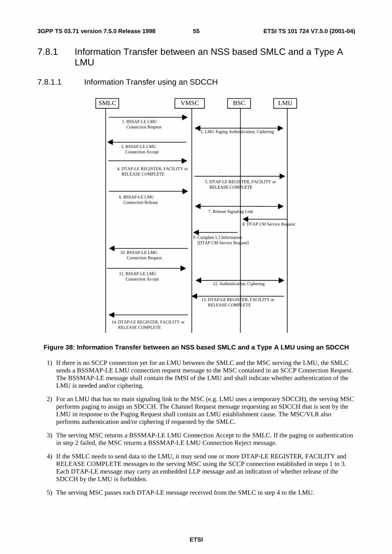
ETSI
ETSI TS 101 724 V7.5.0 (2001-04)553GPP TS 03.71 version 7.5.0 Release 1998
7.8.1 Information Transfer between an NSS based SMLC and a Type A LMU
7.8.1.1 Information Transfer using an SDCCH
LMUBSCSMLC VMSC
2. LMU Paging Authentication, Ciphering
8. DTAP CM Service Request
7. Release Signaling Link
12. Authentication, Ciphering
9. Complete L3 Information[DTAP CM Service Request]
1. BSSAP-LE LMU Connection Request
3. BSSAP-LE LMU Connection Accept
4. DTAP-LE REGISTER, FACILITY or RELEASE COMPLETE
5. DTAP-LE REGISTER, FACILITY or RELEASE COMPLETE
6. BSSAP-LE LMU Connection Release
10. BSSAP-LE LMU Connection Request
11. BSSAP-LE LMU Connection Accept
13. DTAP-LE REGISTER, FACILITY or RELEASE COMPLETE
14. DTAP-LE REGISTER, FACILITY or RELEASE COMPLETE
Figure 38: Information Transfer between an NSS based SMLC and a Type A LMU using an SDCCH
1) If there is no SCCP connection yet for an LMU between the SMLC and the MSC serving the LMU, the SMLC sends a BSSMAP-LE LMU connection request message to the MSC contained in an SCCP Connection Request. The BSSMAP-LE message shall contain the IMSI of the LMU and shall indicate whether authentication of the LMU is needed and/or ciphering.
2) For an LMU that has no main signaling link to the MSC (e.g. LMU uses a temporary SDCCH), the serving MSC performs paging to assign an SDCCH. The Channel Request message requesting an SDCCH that is sent by the LMU in response to the Paging Request shall contain an LMU establishment cause. The MSC/VLR also performs authentication and/or ciphering if requested by the SMLC.
3) The serving MSC returns a BSSMAP-LE LMU Connection Accept to the SMLC. If the paging or authentication in step 2 failed, the MSC returns a BSSMAP-LE LMU Connection Reject message.
4) If the SMLC needs to send data to the LMU, it may send one or more DTAP-LE REGISTER, FACILITY and RELEASE COMPLETE messages to the serving MSC using the SCCP connection established in steps 1 to 3. Each DTAP-LE message may carry an embedded LLP message and an indication of whether release of the SDCCH by the LMU is forbidden.
5) The serving MSC passes each DTAP-LE message received from the SMLC in step 4 to the LMU.
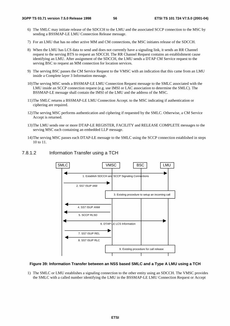
ETSI
ETSI TS 101 724 V7.5.0 (2001-04)563GPP TS 03.71 version 7.5.0 Release 1998
6) The SMLC may initiate release of the SDCCH to the LMU and the associated SCCP connection to the MSC by sending a BSSMAP-LE LMU Connection Release message.
7) For an LMU that has no other active MM and CM connections, the MSC initiates release of the SDCCH.
8) When the LMU has LCS data to send and does not currently have a signaling link, it sends an RR Channel request to the serving BTS to request an SDCCH. The RR Channel Request contains an establishment cause identifying an LMU. After assignment of the SDCCH, the LMU sends a DTAP CM Service request to the serving BSC to request an MM connection for location services.
9) The serving BSC passes the CM Service Request to the VMSC with an indication that this came from an LMU inside a Complete layer 3 Information message.
10) The serving MSC sends a BSSMAP-LE LMU Connection Request message to the SMLC associated with the LMU inside an SCCP connection request (e.g. use IMSI or LAC association to determine the SMLC). The BSSMAP-LE message shall contain the IMSI of the LMU and the address of the MSC.
11) The SMLC returns a BSSMAP-LE LMU Connection Accept. to the MSC indicating if authentication or ciphering are required.
12) The serving MSC performs authentication and ciphering if requested by the SMLC. Otherwise, a CM Service Accept is returned.
13) The LMU sends one or more DTAP-LE REGISTER, FACILITY and RELEASE COMPLETE messages to the serving MSC each containing an embedded LLP message.
14) The serving MSC passes each DTAP-LE message to the SMLC using the SCCP connection established in steps 10 to 11.
7.8.1.2 Information Transfer using a TCH
4. SS7 ISUP ANM
7. SS7 ISUP REL
8. SS7 ISUP RLC
LMUBSCSMLC VMSC
1. Establish SDCCH and SCCP Signaling Connections
6. DTAP-LE LCS Information
2. SS7 ISUP IAM
5. SCCP RLSD
3. Existing procedure to setup an incoming call
9. Existing procedure for call release
Figure 39: Information Transfer between an NSS based SMLC and a Type A LMU using a TCH
1) The SMLC or LMU establishes a signaling connection to the other entity using an SDCCH. The VMSC provides the SMLC with a called number identifying the LMU in the BSSMAP-LE LMU Connection Request or Accept
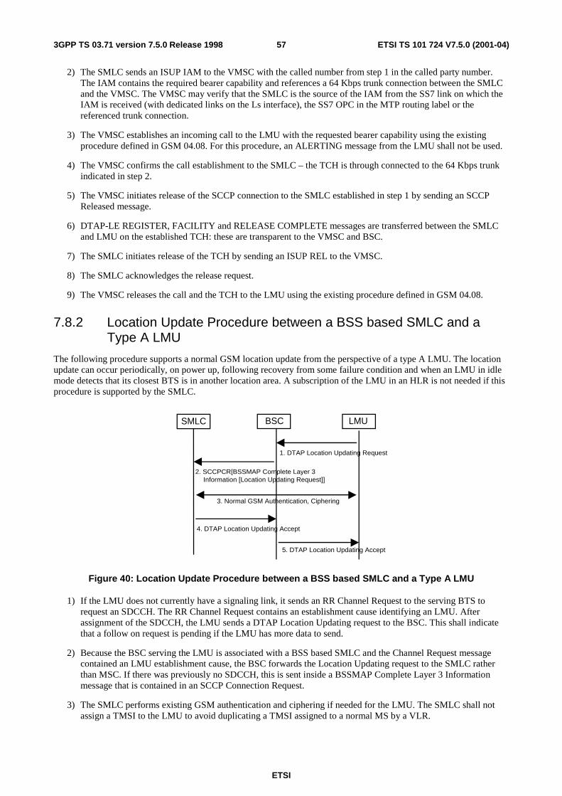
ETSI
ETSI TS 101 724 V7.5.0 (2001-04)573GPP TS 03.71 version 7.5.0 Release 1998
2) The SMLC sends an ISUP IAM to the VMSC with the called number from step 1 in the called party number. The IAM contains the required bearer capability and references a 64 Kbps trunk connection between the SMLC and the VMSC. The VMSC may verify that the SMLC is the source of the IAM from the SS7 link on which the IAM is received (with dedicated links on the Ls interface), the SS7 OPC in the MTP routing label or the referenced trunk connection.
3) The VMSC establishes an incoming call to the LMU with the requested bearer capability using the existing procedure defined in GSM 04.08. For this procedure, an ALERTING message from the LMU shall not be used.
4) The VMSC confirms the call establishment to the SMLC – the TCH is through connected to the 64 Kbps trunk indicated in step 2.
5) The VMSC initiates release of the SCCP connection to the SMLC established in step 1 by sending an SCCP Released message.
6) DTAP-LE REGISTER, FACILITY and RELEASE COMPLETE messages are transferred between the SMLC and LMU on the established TCH: these are transparent to the VMSC and BSC.
7) The SMLC initiates release of the TCH by sending an ISUP REL to the VMSC.
8) The SMLC acknowledges the release request.
9) The VMSC releases the call and the TCH to the LMU using the existing procedure defined in GSM 04.08.
7.8.2 Location Update Procedure between a BSS based SMLC and a Type A LMU
The following procedure supports a normal GSM location update from the perspective of a type A LMU. The location update can occur periodically, on power up, following recovery from some failure condition and when an LMU in idle mode detects that its closest BTS is in another location area. A subscription of the LMU in an HLR is not needed if this procedure is supported by the SMLC.
LMUBSCSMLC
1. DTAP Location Updating Request
3. Normal GSM Authentication, Ciphering
2. SCCPCR[BSSMAP Complete Layer 3Information [Location Updating Request]]
4. DTAP Location Updating Accept
5. DTAP Location Updating Accept
Figure 40: Location Update Procedure between a BSS based SMLC and a Type A LMU
1) If the LMU does not currently have a signaling link, it sends an RR Channel Request to the serving BTS to request an SDCCH. The RR Channel Request contains an establishment cause identifying an LMU. After assignment of the SDCCH, the LMU sends a DTAP Location Updating request to the BSC. This shall indicate that a follow on request is pending if the LMU has more data to send.
2) Because the BSC serving the LMU is associated with a BSS based SMLC and the Channel Request message contained an LMU establishment cause, the BSC forwards the Location Updating request to the SMLC rather than MSC. If there was previously no SDCCH, this is sent inside a BSSMAP Complete Layer 3 Information message that is contained in an SCCP Connection Request.
3) The SMLC performs existing GSM authentication and ciphering if needed for the LMU. The SMLC shall not assign a TMSI to the LMU to avoid duplicating a TMSI assigned to a normal MS by a VLR.
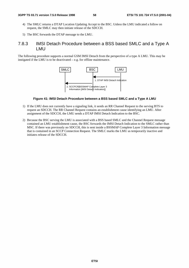
ETSI
ETSI TS 101 724 V7.5.0 (2001-04)583GPP TS 03.71 version 7.5.0 Release 1998
4) The SMLC returns a DTAP Location Updating Accept to the BSC. Unless the LMU indicated a follow on request, the SMLC may then initiate release of the SDCCH.
5) The BSC forwards the DTAP message to the LMU.
7.8.3 IMSI Detach Procedure between a BSS based SMLC and a Type A LMU
The following procedure supports a normal GSM IMSI Detach from the perspective of a type A LMU. This may be instigated if the LMU is to be deactivated – e.g. for offline maintenance.
LMUBSCSMLC
1. DTAP IMSI Detach Indication
2. SCCPCR[BSSMAP Complete Layer 3Information [IMSI Detach Indication]]
Figure 41: IMSI Detach Procedure between a BSS based SMLC and a Type A LMU
1) If the LMU does not currently have a signaling link, it sends an RR Channel Request to the serving BTS to request an SDCCH. The RR Channel Request contains an establishment cause identifying an LMU. After assignment of the SDCCH, the LMU sends a DTAP IMSI Detach Indication to the BSC.
2) Because the BSC serving the LMU is associated with a BSS based SMLC and the Channel Request message contained an LMU establishment cause, the BSC forwards the IMSI Detach Indication to the SMLC rather than MSC. If there was previously no SDCCH, this is sent inside a BSSMAP Complete Layer 3 Information message that is contained in an SCCP Connection Request. The SMLC marks the LMU as temporarily inactive and initiates release of the SDCCH.
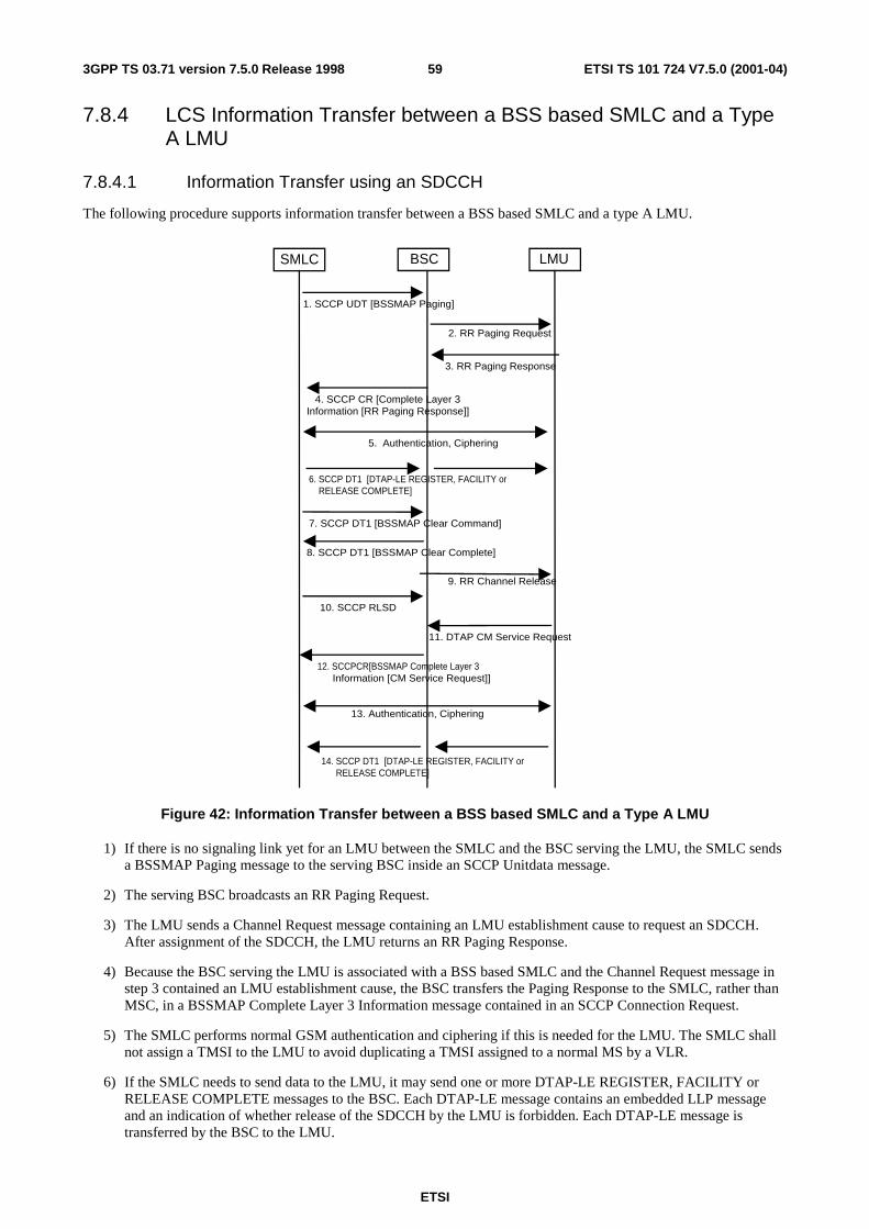
ETSI
ETSI TS 101 724 V7.5.0 (2001-04)593GPP TS 03.71 version 7.5.0 Release 1998
7.8.4 LCS Information Transfer between a BSS based SMLC and a Type A LMU
7.8.4.1 Information Transfer using an SDCCH
The following procedure supports information transfer between a BSS based SMLC and a type A LMU.
LMUBSCSMLC
6. SCCP DT1 [DTAP-LE REGISTER, FACILITY or RELEASE COMPLETE]
11. DTAP CM Service Request
9. RR Channel Release
13. Authentication, Ciphering
1. SCCP UDT [BSSMAP Paging]
2. RR Paging Request
3. RR Paging Response
4. SCCP CR [Complete Layer 3Information [RR Paging Response]]
5. Authentication, Ciphering
7. SCCP DT1 [BSSMAP Clear Command]
8. SCCP DT1 [BSSMAP Clear Complete]
10. SCCP RLSD
12. SCCPCR[BSSMAP Complete Layer 3Information [CM Service Request]]
14. SCCP DT1 [DTAP-LE REGISTER, FACILITY or RELEASE COMPLETE]
Figure 42: Information Transfer between a BSS based SMLC and a Type A LMU
1) If there is no signaling link yet for an LMU between the SMLC and the BSC serving the LMU, the SMLC sends a BSSMAP Paging message to the serving BSC inside an SCCP Unitdata message.
2) The serving BSC broadcasts an RR Paging Request.
3) The LMU sends a Channel Request message containing an LMU establishment cause to request an SDCCH. After assignment of the SDCCH, the LMU returns an RR Paging Response.
4) Because the BSC serving the LMU is associated with a BSS based SMLC and the Channel Request message in step 3 contained an LMU establishment cause, the BSC transfers the Paging Response to the SMLC, rather than MSC, in a BSSMAP Complete Layer 3 Information message contained in an SCCP Connection Request.
5) The SMLC performs normal GSM authentication and ciphering if this is needed for the LMU. The SMLC shall not assign a TMSI to the LMU to avoid duplicating a TMSI assigned to a normal MS by a VLR.
6) If the SMLC needs to send data to the LMU, it may send one or more DTAP-LE REGISTER, FACILITY or RELEASE COMPLETE messages to the BSC. Each DTAP-LE message contains an embedded LLP message and an indication of whether release of the SDCCH by the LMU is forbidden. Each DTAP-LE message is transferred by the BSC to the LMU.
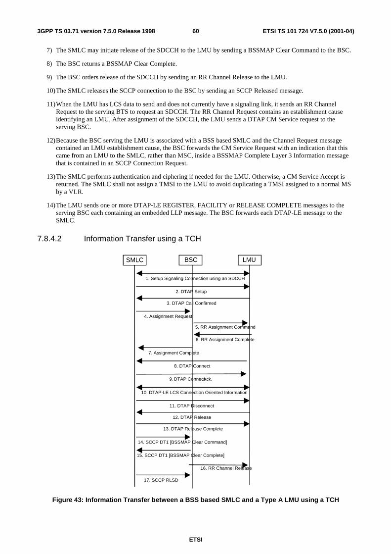
ETSI
ETSI TS 101 724 V7.5.0 (2001-04)603GPP TS 03.71 version 7.5.0 Release 1998
7) The SMLC may initiate release of the SDCCH to the LMU by sending a BSSMAP Clear Command to the BSC.
8) The BSC returns a BSSMAP Clear Complete.
9) The BSC orders release of the SDCCH by sending an RR Channel Release to the LMU.
10) The SMLC releases the SCCP connection to the BSC by sending an SCCP Released message.
11) When the LMU has LCS data to send and does not currently have a signaling link, it sends an RR Channel Request to the serving BTS to request an SDCCH. The RR Channel Request contains an establishment cause identifying an LMU. After assignment of the SDCCH, the LMU sends a DTAP CM Service request to the serving BSC.
12) Because the BSC serving the LMU is associated with a BSS based SMLC and the Channel Request message contained an LMU establishment cause, the BSC forwards the CM Service Request with an indication that this came from an LMU to the SMLC, rather than MSC, inside a BSSMAP Complete Layer 3 Information message that is contained in an SCCP Connection Request.
13) The SMLC performs authentication and ciphering if needed for the LMU. Otherwise, a CM Service Accept is returned. The SMLC shall not assign a TMSI to the LMU to avoid duplicating a TMSI assigned to a normal MS by a VLR.
14) The LMU sends one or more DTAP-LE REGISTER, FACILITY or RELEASE COMPLETE messages to the serving BSC each containing an embedded LLP message. The BSC forwards each DTAP-LE message to the SMLC.
7.8.4.2 Information Transfer using a TCH
LMUBSCSMLC
16. RR Channel Release
4. Assignment Request
5. RR Assignment Command
6. RR Assignment Complete
7. Assignment Complete
8. DTAP Connect
14. SCCP DT1 [BSSMAP Clear Command]
15. SCCP DT1 [BSSMAP Clear Complete]
17. SCCP RLSD
1. Setup Signaling Connection using an SDCCH
2. DTAP Setup
3. DTAP Call Confirmed
9. DTAP Connect Ack.
10. DTAP-LE LCS Connection Oriented Information
11. DTAP Disconnect
12. DTAP Release
13. DTAP Release Complete
Figure 43: Information Transfer between a BSS based SMLC and a Type A LMU using a TCH
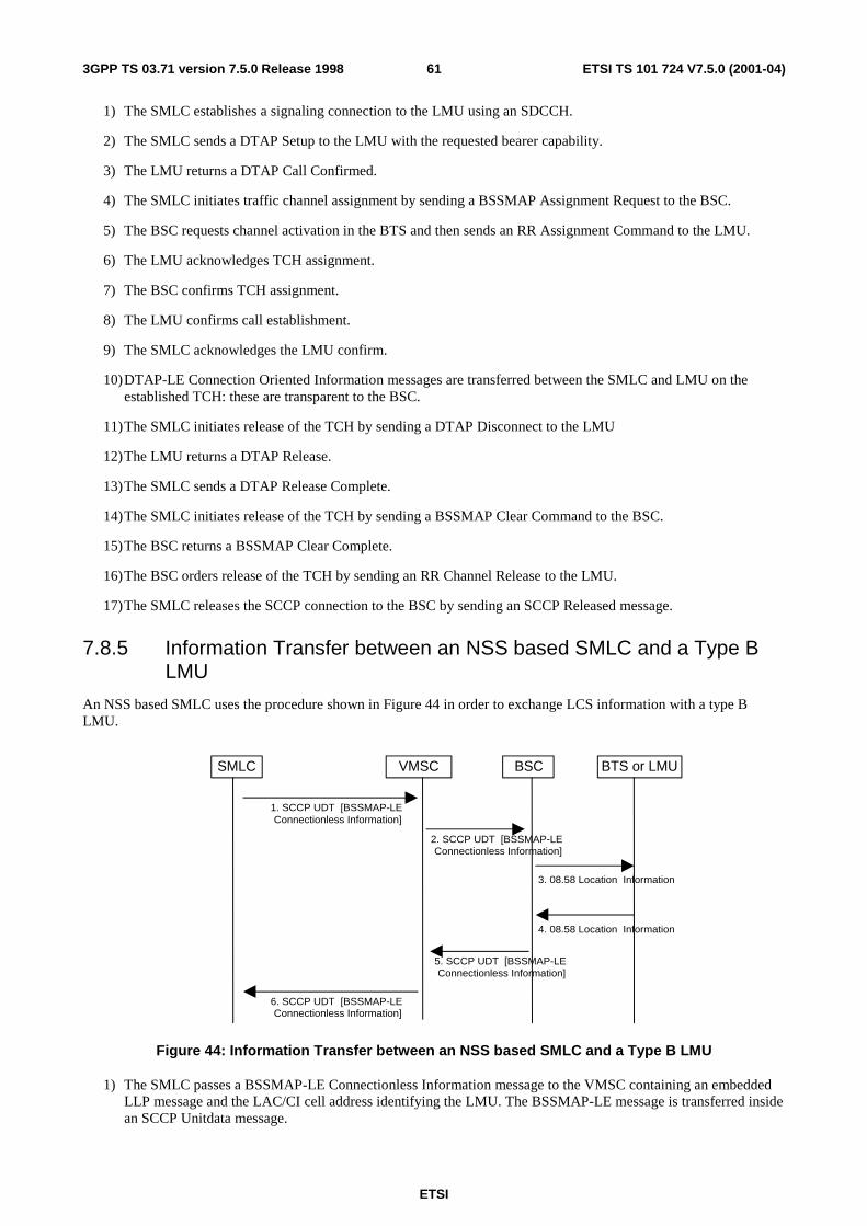
ETSI
ETSI TS 101 724 V7.5.0 (2001-04)613GPP TS 03.71 version 7.5.0 Release 1998
1) The SMLC establishes a signaling connection to the LMU using an SDCCH.
2) The SMLC sends a DTAP Setup to the LMU with the requested bearer capability.
3) The LMU returns a DTAP Call Confirmed.
4) The SMLC initiates traffic channel assignment by sending a BSSMAP Assignment Request to the BSC.
5) The BSC requests channel activation in the BTS and then sends an RR Assignment Command to the LMU.
6) The LMU acknowledges TCH assignment.
7) The BSC confirms TCH assignment.
8) The LMU confirms call establishment.
9) The SMLC acknowledges the LMU confirm.
10) DTAP-LE Connection Oriented Information messages are transferred between the SMLC and LMU on the established TCH: these are transparent to the BSC.
11) The SMLC initiates release of the TCH by sending a DTAP Disconnect to the LMU
12) The LMU returns a DTAP Release.
13) The SMLC sends a DTAP Release Complete.
14) The SMLC initiates release of the TCH by sending a BSSMAP Clear Command to the BSC.
15) The BSC returns a BSSMAP Clear Complete.
16) The BSC orders release of the TCH by sending an RR Channel Release to the LMU.
17) The SMLC releases the SCCP connection to the BSC by sending an SCCP Released message.
7.8.5 Information Transfer between an NSS based SMLC and a Type B LMU
An NSS based SMLC uses the procedure shown in Figure 44 in order to exchange LCS information with a type B LMU.
1. SCCP UDT [BSSMAP-LEConnectionless Information]
6. SCCP UDT [BSSMAP-LEConnectionless Information]
BTS or LMUBSCSMLC VMSC
2. SCCP UDT [BSSMAP-LEConnectionless Information]
3. 08.58 Location Information
5. SCCP UDT [BSSMAP-LEConnectionless Information]
4. 08.58 Location Information
Figure 44: Information Transfer between an NSS based SMLC and a Type B LMU
1) The SMLC passes a BSSMAP-LE Connectionless Information message to the VMSC containing an embedded LLP message and the LAC/CI cell address identifying the LMU. The BSSMAP-LE message is transferred inside an SCCP Unitdata message.
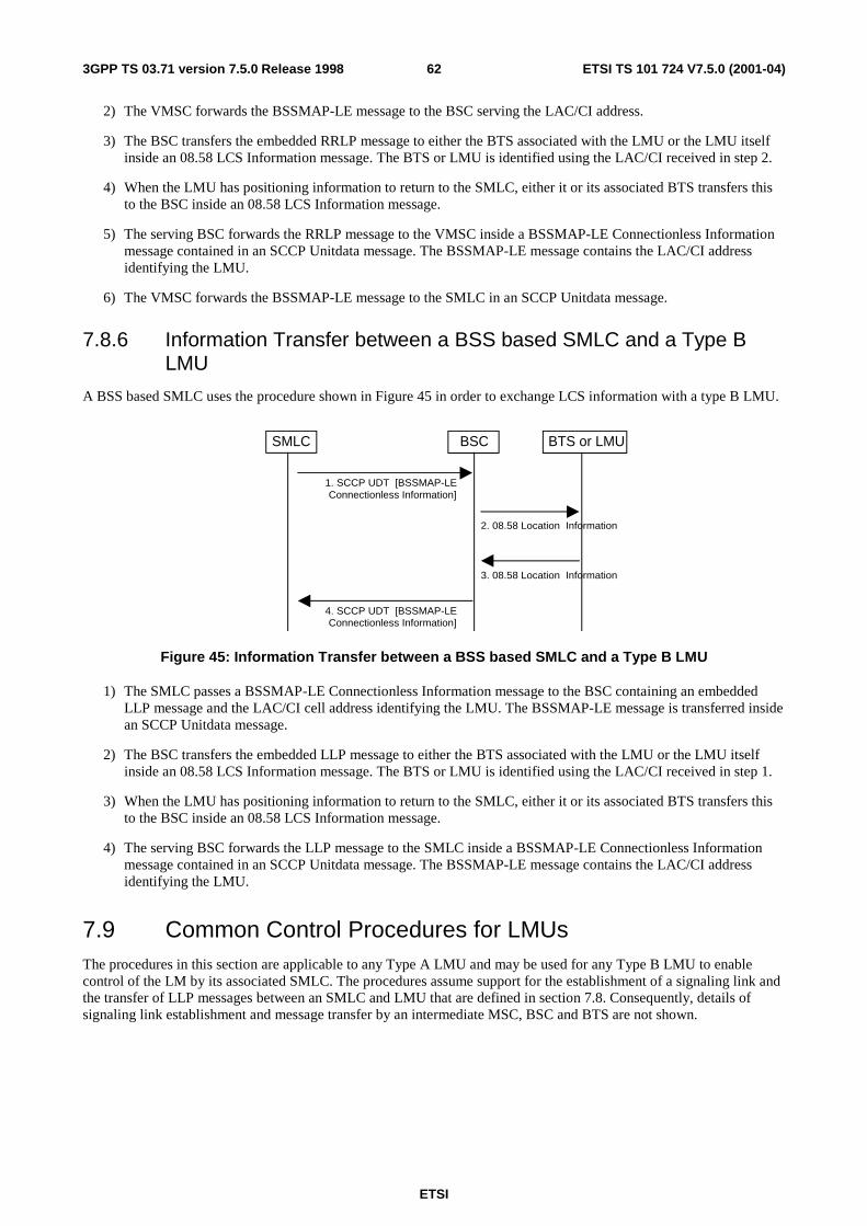
ETSI
ETSI TS 101 724 V7.5.0 (2001-04)623GPP TS 03.71 version 7.5.0 Release 1998
2) The VMSC forwards the BSSMAP-LE message to the BSC serving the LAC/CI address.
3) The BSC transfers the embedded RRLP message to either the BTS associated with the LMU or the LMU itself inside an 08.58 LCS Information message. The BTS or LMU is identified using the LAC/CI received in step 2.
4) When the LMU has positioning information to return to the SMLC, either it or its associated BTS transfers this to the BSC inside an 08.58 LCS Information message.
5) The serving BSC forwards the RRLP message to the VMSC inside a BSSMAP-LE Connectionless Information message contained in an SCCP Unitdata message. The BSSMAP-LE message contains the LAC/CI address identifying the LMU.
6) The VMSC forwards the BSSMAP-LE message to the SMLC in an SCCP Unitdata message.
7.8.6 Information Transfer between a BSS based SMLC and a Type B LMU
A BSS based SMLC uses the procedure shown in Figure 45 in order to exchange LCS information with a type B LMU.
1. SCCP UDT [BSSMAP-LEConnectionless Information]
4. SCCP UDT [BSSMAP-LEConnectionless Information]
BTS or LMUBSCSMLC
2. 08.58 Location Information
3. 08.58 Location Information
Figure 45: Information Transfer between a BSS based SMLC and a Type B LMU
1) The SMLC passes a BSSMAP-LE Connectionless Information message to the BSC containing an embedded LLP message and the LAC/CI cell address identifying the LMU. The BSSMAP-LE message is transferred inside an SCCP Unitdata message.
2) The BSC transfers the embedded LLP message to either the BTS associated with the LMU or the LMU itself inside an 08.58 LCS Information message. The BTS or LMU is identified using the LAC/CI received in step 1.
3) When the LMU has positioning information to return to the SMLC, either it or its associated BTS transfers this to the BSC inside an 08.58 LCS Information message.
4) The serving BSC forwards the LLP message to the SMLC inside a BSSMAP-LE Connectionless Information message contained in an SCCP Unitdata message. The BSSMAP-LE message contains the LAC/CI address identifying the LMU.
7.9 Common Control Procedures for LMUs The procedures in this section are applicable to any Type A LMU and may be used for any Type B LMU to enable control of the LM by its associated SMLC. The procedures assume support for the establishment of a signaling link and the transfer of LLP messages between an SMLC and LMU that are defined in section 7.8. Consequently, details of signaling link establishment and message transfer by an intermediate MSC, BSC and BTS are not shown.
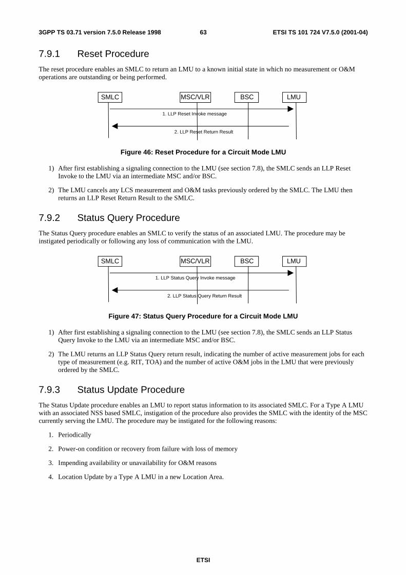
ETSI
ETSI TS 101 724 V7.5.0 (2001-04)633GPP TS 03.71 version 7.5.0 Release 1998
7.9.1 Reset Procedure
The reset procedure enables an SMLC to return an LMU to a known initial state in which no measurement or O&M operations are outstanding or being performed.
LMUBSCSMLC MSC/VLR
1. LLP Reset Invoke message
2. LLP Reset Return Result
Figure 46: Reset Procedure for a Circuit Mode LMU
1) After first establishing a signaling connection to the LMU (see section 7.8), the SMLC sends an LLP Reset Invoke to the LMU via an intermediate MSC and/or BSC.
2) The LMU cancels any LCS measurement and O&M tasks previously ordered by the SMLC. The LMU then returns an LLP Reset Return Result to the SMLC.
7.9.2 Status Query Procedure
The Status Query procedure enables an SMLC to verify the status of an associated LMU. The procedure may be instigated periodically or following any loss of communication with the LMU.
LMUBSCSMLC MSC/VLR
1. LLP Status Query Invoke message
2. LLP Status Query Return Result
Figure 47: Status Query Procedure for a Circuit Mode LMU
1) After first establishing a signaling connection to the LMU (see section 7.8), the SMLC sends an LLP Status Query Invoke to the LMU via an intermediate MSC and/or BSC.
2) The LMU returns an LLP Status Query return result, indicating the number of active measurement jobs for each type of measurement (e.g. RIT, TOA) and the number of active O&M jobs in the LMU that were previously ordered by the SMLC.
7.9.3 Status Update Procedure
The Status Update procedure enables an LMU to report status information to its associated SMLC. For a Type A LMU with an associated NSS based SMLC, instigation of the procedure also provides the SMLC with the identity of the MSC currently serving the LMU. The procedure may be instigated for the following reasons:
1. Periodically
2. Power-on condition or recovery from failure with loss of memory
3. Impending availability or unavailability for O&M reasons
4. Location Update by a Type A LMU in a new Location Area.

ETSI
ETSI TS 101 724 V7.5.0 (2001-04)643GPP TS 03.71 version 7.5.0 Release 1998
LMUBSCSMLC MSC/VLR
1. LLP Status Update Invoke message
2. LLP Status Update Return Result
Figure 48: Status Update Procedure for a Circuit Mode LMU
1) After first establishing a signaling connection to the SMLC (see section 7.8), the LMU sends an LLP Status Update Invoke to the SMLC via an intermediate MSC and/or BSC. This message shall include the reason for the Status Update, the number of active and outstanding jobs of each category in the LMU and the current hardware status.
2) The SMLC returns an LLP Status Update return result to acknowledge receipt of the Status Update.
7.10 Common Procedures supporting Interaction between Peer SMLCs
7.10.1 Information Transfer between Peer SMLCs
Figure 49 illustrates LCS information transfer between peer SMLCs where, in this scenario, one SMLC is NSS based and the other BSS based. It is assumed that while the NSS based SMLC has SS7 links to an STP, the BSS based SMLC does not.
1. SCCP UDT [BSSMAP-LE Connectionless Information]
6. SCCP UDT [BSSMAP-LEConnectionless Information]
BSS SMLCBSCNSS SMLC
MSC
2. SCCP UDT [BSSMAPConnectionless Information]
5. SCCP UDT [BSSMAP
Connectionless Information]
3. SCCP UDT [BSSMAP-LE
Connectionless Information]
4. SCCP UDT [BSSMAP-LE
Connectionless Information]
Figure 49: Information Transfer between an NSS based and a BSS based SMLC
1) When the NSS based SMLC has LCS information to send to another SMLC, it transmits a BSSMAP-LE Connectionless Information message containing an embedded SMLCPP message and the LAC/CI cell address identifying the other SMLC. If an SMLCPP message is too large to fit in a single BSSMAP-LE Connectionless Information message, it may be segmented and transferred inside a sequence of BSSMAP-LE messages. The BSSMAP-LE message is transferred inside an SCCP Unitdata message. The message is routed to an SS7 signaling point code associated with the LAC/CI address. In this scenario, the signaling point code is that for the MSC connected to the BSC for the BSS based SMLC.
2) The MSC forwards the BSSMAP message or a message segment to the BSC associated with the LAC/CI address received in step 1.
3) The BSC transfers the BSSMAP-LE message or a message segment to the SMLC. The BSC recognizes the SMLC as the final destination due to the presence of the embedded SMLCPP message.
ETSI
ETSI TS 101 724 V7.5.0 (2001-04)653GPP TS 03.71 version 7.5.0 Release 1998
4) When the BSS based SMLC has positioning information to return to the NSS based SMLC, it passes this to its associated BSC in a BSSMAP-LE Connectionless message contained in an SCCP Unitdata message. The BSSMAP-LE message contains an embedded SMLCPP message and the LAC/CI address identifying the other SMLC. If an SMLCPP message is too large to fit in a single BSSMAP-LE message, it may be segmented and transferred inside a sequence of BSSMAP-LE messages.
5) The serving BSC forwards the BSSMAP message or a message segment to its MSC.
6) The MSC forwards the BSSMAP-LE message or a message segment directly to the NSS based SMLC in an SCCP Unitdata message. The message is routed to an SS7 signaling point code associated with the LAC/CI address in the BSSMAP-LE message. In this scenario, the signaling point code is that for the NSS based SMLC.
7.11 Exception Procedures The procedures in this section apply to all variants of an MT-LR, NI-LR and MO-LR where a BSSMAP-LE Perform Location Request has been sent to an SMLC by a BSC or MSC requesting some location service (e.g. provision of a location estimate for a target MS or transfer of assistance data to a target MS).
7.11.1 Procedures in the SMLC
When a request for a location estimate fails due to failure of a position method itself (e.g. due to inaccurate or insufficient position measurements and related data) and the SMLC is unable to instigate another positioning attempt (e.g. due to a requirement on response time), the SMLC may return a BSSMAP-LE Perform Location response containing a less accurate location estimate (e.g. based on serving cell and timing advance). If a less accurate estimate is not available or will not meet the accuracy requirement, the SMLC shall instead return a BSSMAP-LE Perform Location response message containing no location estimate and indicating the cause of failure.
When a request for any other location service (e.g. transfer of assistance data to a target MS) fails for any reason and the SMLC is unable to reattempt the service, the SMLC shall return a BSSMAP-LE Perform Location response message indicating the cause of failure.
When a location service request is interrupted by some other unrecoverable error event inside the SMLC, the SMLC shall immediately terminate the location service attempt and return a BSSMAP Perform Location Response message containing the reason for the location service cancellation. In that case, any dialogue previously opened with an LMU or BSC for the purpose of instigating position measurements for any MS being located may also be aborted by the SMLC.
If the SMLC receives a BSSMAP-LE Perform Location Abort indication for a previous location service request from the VMSC (NSS based SMLC) or BSC (BSS based SMLC), it shall immediately terminate the location service attempt and may abort any dialogues used for the location service attempt that may still exist with any LMUs. Although the SMLC cannot abort any location procedure instigated in the serving BSC (e.g. for TOA), the circumstances of the abort may still ensure cancellation of any such procedure (see section on BSC).
If the SMLC has instigated any location releated procedure in the Target MS or its serving BSC and receives a BSSLAP Reject, BSSLAP Abort or BSSLAP Reset indication from the BSC, it shall cancel the location service attempt and may abort any dialogues for this that currently exist with any LMUs. For a BSSLAP Abort, the SMLC shall then either return any location estimate already derived, if this was requested and is sufficient for the requested QoS, or return a BSSMAP-LE Perform Location response indicating failure of the location service and the cause of the failure in the BSSLAP Abort. For a BSSLAP Reject and BSSLAP Reset, the SMLC has the additional option of restarting the location service attempt and using the same or a different position method where a location estimate was requested. A decision to restart the location service shall take into account the cause of the location service failure as conveyed in the BSSLAP Reject or BSSLAP Reset and whether, in the case of successful intra-BSC handover, the new cell for the target MS is still associated with the SMLC. If the SMLC receives a BSSLAP Reject or BSSLAP Reset with a cause indicating intra-BSC handover and with a new cell identity for the target MS that is not associated with the SMLC, the SMLC shall return a BSSMAP-LE Perform Location response containing either a location estimate, if requested, available and sufficient for the requested QoS, or a failure cause indicating “intra-BSC” handover.
NOTE: This procedure may only be needed for an NSS-based SMLC.
The SMLC may indicate an inability to support location due to overload by rejecting with a cause indicating congestion a BSSMAP-LE Perform Location request received from either an MSC or BSC.
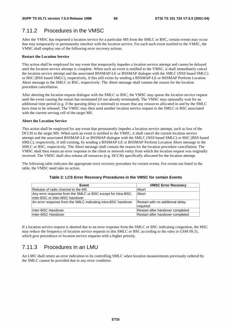
ETSI
ETSI TS 101 724 V7.5.0 (2001-04)663GPP TS 03.71 version 7.5.0 Release 1998
7.11.2 Procedures in the VMSC
After the VMSC has requested a location service for a particular MS from the SMLC or BSC, certain events may occur that may temporarily or permanently interfere with the location service. For each such event notified to the VMSC, the VMSC shall employ one of the following error recovery actions.
Restart the Location Service
This action shall be employed for any event that temporarily impedes a location service attempt and cannot be delayed until the location service attempt is complete. When such an event is notified to the VMSC, it shall immediately cancel the location service attempt and the associated BSSMAP-LE or BSSMAP dialogue with the SMLC (NSS based SMLC) or BSC (BSS based SMLC), respectively, if this still exists by sending a BSSMAP-LE or BSSMAP Perform Location Abort message to the SMLC or BSC, respectively. The Abort message shall contain the reason for the location procedure cancellation.
After aborting the location request dialogue with the SMLC or BSC, the VMSC may queue the location service request until the event causing the restart has terminated (if not already terminated). The VMSC may optionally wait for an additional time period (e.g. if the queuing delay is minimal) to ensure that any resources allocated in and by the SMLC have time to be released. The VMSC may then send another location service request to the SMLC or BSC associated with the current serving cell of the target MS.
Abort the Location Service
This action shall be employed for any event that permanently impedes a location service attempt, such as loss of the DCCH to the target MS. When such an event is notified to the VMSC, it shall cancel the current location service attempt and the associated BSSMAP-LE or BSSMAP dialogue with the SMLC (NSS based SMLC) or BSC (BSS based SMLC), respectively, if still existing, by sending a BSSMAP-LE or BSSMAP Perform Location Abort message to the SMLC or BSC, respectively. The Abort message shall contain the reason for the location procedure cancellation. The VMSC shall then return an error response to the client or network entity from which the location request was originally received. The VMSC shall also release all resources (e.g. DCCH) specifically allocated for the location attempt.
The following table indicates the appropriate error recovery procedure for certain events. For events not listed in the table, the VMSC need take no action.
Table 2: LCS Error Recovery Procedures in the VMSC for certain Events
Event VMSC Error Recovery Release of radio channel to the MS Abort Any error response from the SMLC or BSC except for intra-BSC, inter-BSC or inter-MSC handover
Abort
An error response from the SMLC indicating intra-BSC handover Restart with no additional delay required
Inter-BSC Handover Restart after handover completed Inter-MSC Handover Restart after handover completed
If a location service request is aborted due to an error response from the SMLC or BSC indicating congestion, the MSC may reduce the frequency of location service requests to this SMLC or BSC according to the rules in GSM 09.31, which give precedence to location service requests with a higher priority.
7.11.3 Procedures in an LMU
An LMU shall return an error indication to its controlling SMLC when location measurements previously ordered by the SMLC cannot be provided due to any error condition.
ETSI
ETSI TS 101 724 V7.5.0 (2001-04)673GPP TS 03.71 version 7.5.0 Release 1998
7.11.4 Procedures in the BSC
7.11.4.1 General Procedures
The BSC serving a target MS shall supervise any network or MS location service procedure, including transfer of positioning assistance data to an MS, and shall only allow one such procedure to be active at any time. If a new procedure is instigated by the SMLC for any target MS, the BSC shall cancel any previous procedure without notifying the SMLC or target MS. The new procedure shall then be treated according to the prevailing conditions – e.g. may be rejected if a previous TOA handover attempt was not yet completed. If a location information transfer to an MS initiated by an SMLC is not active, the BSC shall discard any RRLP message or message segment received from the MS. This precludes the initiation of any location service procedure from an MS.
Depending on the location procedure and its current state of execution, a serving BSC may chose to defer certain radio related events (e.g. handover) to avoid interference with location – refer to the later sections for each position method. A serving BSC shall abort all existing location related procedures for a particular target MS without notifying an NSS based SMLC or target MS if the DCCH to the target MS or the SCCP connection to the VMSC or a BSS based SMLC is released. In the event of an abort with a BSS based SMLC, the BSC shall attempt to notify the SMLC using a BSSMAP-LE Perform Location Abort.
7.11.4.2 Rejection of an SMLC Positioning Request
The BSC may reject any request from an SMLC for positioning or transfer of assistance data for a target MS if the request cannot be performed for reasons other than interaction with handover or other RR management. If the request is rejected, the BSC shall return a BSSLAP Reject to the SMLC containing the cause of rejection.
7.11.4.3 Interaction with Inter-BSC or Inter-MSC Handover
The BSC shall reject any request from an SMLC for positioning or transfer of assistance data while an inter-BSC or inter-MSC handover procedure is ongoing and shall return a BSSLAP Abort to the SMLC.
The BSC shall terminate any network or MS positioning procedure or any transfer of RRLP assistance data already in progress if inter-BSC or inter-MSC handover is needed and is not precluded by the particular location procedure and its current state. When a location procedure is terminated and there is an active BSSLAP transaction, the BSC shall return a BSSLAP Abort message to the SMLC after the BSSMAP Handover Required has been sent to the serving MSC. The BSSLAP Abort shall contain the cause of the location procedure failure. When a location procedure is terminated and there is no active BSSLAP transaction, the BSC shall send a BSSAP-LE Perform Location Abort message to the SMLC after the BSSMAP Handover Required has been sent to the serving MSC.
7.11.4.4 Interaction with Intra-BSC Handover and other RR Management Procedures
The BSC shall reject any request from an SMLC for positioning or transfer of assistance data while an intra-BSC handover or other intra-BSC RR management procedure involving the target MS is ongoing and shall return a BSSLAP Reset to the SMLC when the handover or other RR management procedure is complete or has timed out in the BSC.
The BSC shall terminate any network or MS positioning procedure or any transfer of RRLP assistance data already in progress if an intra-BSC handover or other intra-BSC RR management procedure is needed and is not precluded by the particular location procedure and its current state. When location procedure is terminated, the BSC shall return a BSSLAP Reset message to the SMLC after the intra-BSC handover or other RR management procedure is complete or has timed out in the BSC. The BSSLAP Reset shall contain a cause indication, the current serving cell identity and may contain measurement information for the target MS (e.g. TA value).
7.11.4.5 Priority of Handover and Other RR Management Procedures
If the transfer of RRLP messages between an SMLC and target MS is interrupted by intra-BSC handover, inter-BSC handover or any other intra-BSC RR management procedure, the BSC shall avoid delay to the handover or RR management procedure by employing the preemption capability defined in GSM 04.06 and 04.08. This allows an RR Handover Command or other RR management command sent to the target MS to be assigned a “high” priority at the data link level enabling preemption of “low” priority RR Application Information messages (carrying RRLP messages) which may have been sent earlier. This procedure ensures that any RRLP data still untransmitted to the MS will be
ETSI
ETSI TS 101 724 V7.5.0 (2001-04)683GPP TS 03.71 version 7.5.0 Release 1998
preempted (and discarded) by the data link layer in the BTS prior to transmission of the Handover Command or other RR Management command.
7.11.4.6 Interaction with Segmentation
When requested to transfer a segmented RRLP message between an SMLC and target MS, the BSC shall discard all received RRLP segments if the transfer procedure in the BSC cannot be supported or is aborted. The BSC need not wait until all RRLP segments are received before notifying the SMLC of the failure of the RRLP procedure with a BSSLAP Abort, Reject or Reset message.
If a location service procedure for a target MS is not currently underway or previously failed, the BSC shall discard all BSSLAP segments received from an SMLC for this MS until it receives the first or only segment of a new BSSLAP message. Once a location service procedure has been started involving RRLP message transfer to a target MS, the BSC shall discard all RRLP segments received from the MS until it receives the first or only segment of a new RRLP message. The new RRLP message shall then be treated according to the state of the RRLP message transfer as described in section 7.7.
Further details regarding transfer and segmentation of RRLP messages between a BSC and MS can be found in GSM 04.08.
7.11.4.7 Overload
The BSC may indicate an inability to support location due to overload by rejecting with a cause indicating congestion a BSSMAP Perform Location request received from the MSC. If a BSS based SMLC has rejected a request from the BSC to perform location with a cause indicating congestion, the BSC shall convey the rejection and cause to the MSC if the request was MSC initiated. If the request was initiated by the BSC, the BSC may reduce the frequency of its location requests to the SMLC according to the rules in GSM 09.31, which give precedence to location service requests with a higher priority.
7.11.5 Procedures in the Target MS
A target MS shall terminate any positioning procedure or the transfer of RRLP positioning assistance data without sending any response to the SMLC if any RR message is received from the BSC that starts some other RR management procedure, including a new positioning procedure. The new RR procedure shall then be executed by the MS.
7.11.6 Further Procedures for Handover
7.11.6.1 MSC procedure for Inter-MSC Handover
When a location estimate is required for a target MS with an established call in a state of inter-MSC handover, the serving cell ID or serving location area ID shall be used by the visited MSC to identify the correct SMLC to perform the location. All layer-3 BSSMAP and DTAP Location request related messages that are transferred over the A-interface shall now be sent via MAP/E interface piggy-backed in MAP_FORWARD_ACCESS_SIGNALLING and MAP PROCESS_ACCESS_SIGNALLING between the visited and serving MSCs.
7.11.6.2 Handling of an ongoing handover while a request for positioning arrives at MSC/VLR
If during an ongoing radio handover procedure a request for location information arrives at the MSC/VLR, the request shall be suspended until the HANDOVER COMPLETE message is received at the MSC/VLR. On completion of the handover, the MSC/VLR shall issue continue with location preparation procedure.
ETSI
ETSI TS 101 724 V7.5.0 (2001-04)693GPP TS 03.71 version 7.5.0 Release 1998
7.12 Privacy
7.12.1 Privacy Override Indicator (POI)
The POI is used to determine whether the privacy settings of the subscriber to be positioned shall be overridden by the request for location services. The assignment of a POI value with an ’override’ or ’not override’ value in the LCS client profile is done during the LCS client provisioning. The type of LCS client requesting location information (i.e.emergency, law-enforcement etc.) shall determine the value of the POI assigned to the LCS client profile.
There are two distinct cases regarding the handling of the privacy override indicator.
Procedure A: If the subscriber to be positioned is in the same PLMN or same country as the GMLC then the POI shall override the subscriber’s privacy options.
Procedure B: Otherwise the POI shall not override the subscriber’s privacy options.
7.12.2 Privacy Procedures
The SLPP shall contain the privacy options defined in the HLR of the MS subscriber.
The SLPP shall be downloaded to the VMSC together with the rest of his subscription information in the existing MAP operation INSERT_SUBSCRIBER_DATA. It will be deleted with the existing MAP operation DELETE_SUBSCRIBER_DATA.
The POI is transferred from the GMLC to the VMSC in the location request. Based on the location of the GMLC the VMSC evaluates whether to accept or ignore the received POI according to the definition in Section 6.6.1.
If the POI is accepted the location requested is unconditionally performed. Otherwise if the POI is ignored the VMSC evaluates the privacy options in the MS subscriber’s subscription profile (assuming this is held in the VLR). If the VLR does not contain the MS subscription profile, LCS will rely on the existing GSM recovery mechanisms to obtain the profile.
If the location request is allowed by the privacy options the location request is performed. Otherwise, if the location request is barred by the privacy options, the location request is refused an error response is returned to the GMLC with a cause code indicating that the request was rejected by the subscriber.
7.12.3 MS Privacy Options
The MS privacy options in the SLPP apply to an MT-LR or NI-LR and either indicate that no MT-LR or NI-LR is allowed for the MS (except as may be overridden by the POI or local regulatory requirements) or define the particular classes of LCS client for which an MT-LR or NI-LR for location are allowed, with the following classes being possible:
a) Universal Class – allow positioning by all LCS clients
b) Call related Class – comprises any LCS client to which the MS originated a call that is currently established. For all clients in the call related class, one of the following subscription options shall apply:
- positioning allowed without notifying the MS user (default case);
- positioning allowed with notification to the MS user;
- positioning requires notification and verification by the MS user; positioning is allowed only if granted by the MS user or if there is no response to the notification;
- positioning requires notification and verification by the MS user; positioning is allowed only if granted by the MS user;
ETSI
ETSI TS 101 724 V7.5.0 (2001-04)703GPP TS 03.71 version 7.5.0 Release 1998
c) Non-Call related Class – allow positioning by specific identified LCS Clients or groups of LCS Client with the following restrictions allowed for each identified LCS Client or group of LCS Clients
- Location request allowed only from GMLCs identified in the SLPP
- Location request allowed only from a GMLC in the home country
- Location request allowed from any GMLC
For each identified value added LCS client in the privacy exception list one of the following subscription options shall apply:
- positioning allowed without notifying the MS user (default case);
- positioning allowed with notification to the MS user;
- positioning requires notification and verification by the MS user; positioning is allowed only if granted by the MS user or if there is no response to the notification;
- positioning requires notification and verification by the MS user; positioning is allowed only if granted by the MS user;
For all value added LCS clients sending a non-call related MT-LR that are not identified in the privacy exception list, one of the following subscription option shall apply:
- positioning not allowed (default case);
- positioning allowed with notification to the MS user;
- positioning requires notification and verification by the MS user; positioning is allowed only if granted by the MS user or if there is no response to the notification;
- positioning requires notification and verification by the MS user; positioning is allowed only if granted by the MS user;
d) PLMN operator Class – allow positioning by specific types of client within or associated with the VPLMN, with the following types of client identified:
- clients providing a location related broadcast service
- O&M client in the HPLMN (when the MS is currently being served by the HPLMN)
- O&M client in the VPLMN
- Clients recording anonymous location information without any MS identifier
- Clients enhancing or supporting any supplementary service, IN service, bearer service or teleservice subscribed to by the target MS subscriber
If the MS subscribes to the universal class, any MT-LR or NI-LR shall be allowed by the VMSC. If local regulatory requirements mandate it, any MT-LR for an emergency services LCS client and any NI-LR for an emergency services call origination shall be allowed by the VMSC.
If the MS subscribes to the call-related class, an MT-LR may be allowed if the MS previously originated a call that is still established and the called party number dialed by the MS matches the called party number received from the GMLC. If the called party number conditions are satisfied, the MT-LR shall be allowed if the MS user subscribes to either location without notification or location with notification. If the MS user subscribes to location with notification and privacy verification, the MT-LR shall be allowed following notification to the MS if the MS user either returns a response indicating that location is allowed or returns no response but subscribes to allowing location in the absence of a response. In all other cases, the MT-LR shall be restricted.
If the MS subscribes to the non-call related class, an MT-LR may be allowed by the network if the identity of the LCS client or LCS client group supplied by the GMLC matches the identity of any LCS Client or LCS Client group contained in the MS's SLPP and any other GMLC restrictions associated with this LCS Client identity in the SLPP are also met. If the LCS client is correctly matched in this way and any GMLC restrictions are satisfied, the MT-LR shall be allowed if the MS user subscribes to either location without notification or location with notification. If the MS user
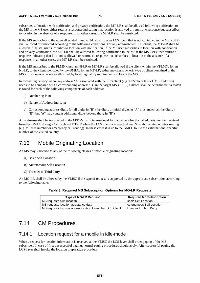
ETSI
ETSI TS 101 724 V7.5.0 (2001-04)713GPP TS 03.71 version 7.5.0 Release 1998
subscribes to location with notification and privacy verification, the MT-LR shall be allowed following notification to the MS if the MS user either returns a response indicating that location is allowed or returns no response but subscribes to location in the absence of a response. In all other cases, the MT-LR shall be restricted.
If the MS subscribes to the non-call related class, an MT-LR from an LCS client that is not contained in the MS’s SLPP shall allowed or restricted according to the following conditions. For any non-matched LCS client, the MT-LR shall be allowed if the MS user subscribes to location with notification. If the MS user subscribes to location with notification and privacy verification, the MT-LR shall be allowed following notification to the MS if the MS user either returns a response indicating that location is allowed or returns no response but subscribes to location in the absence of a response. In all other cases, the MT-LR shall be restricted.
If the MS subscribes to the PLMN class, an NI-LR or MT-LR shall be allowed if the client within the VPLMN, for an NI-LR, or the client identified by the GMLC, for an MT-LR, either matches a generic type of client contained in the MS's SLPP or is otherwise authorized by local regulatory requirements to locate the MS.
In evaluating privacy where any address "A" associated with the LCS client (e.g. LCS client ID or GMLC address) needs to be compared with a corresponding address "B" in the target MS's SLPP, a match shall be determined if a match is found for each of the following components of each address:
a) Numbering Plan
b) Nature of Address Indicator
c) Corresponding address digits for all digits in "B" (the digits or initial digits in "A" must match all the digits in "B", but "A" may contain additional digits beyond those in "B")
All addresses shall be transferred to the MSC/VLR in international format, except for the called party number received from the GMLC during a Call Related MT-LR when the LCS client was reached via IN or abbreviated number routing (e.g. toll free number or emergency call routing). In these cases it is up to the GMLC to use the valid national specific number of the visited country.
7.13 Mobile Originating Location An MS may subscribe to any of the following classes of mobile originating location:
A) Basic Self Location
B) Autonomous Self Location
C) Transfer to Third Party
An MO-LR shall be allowed by the VMSC if the type of request is supported by the appropriate subscription according to the following table.
Table 3: Required MS Subscription Options for MO-LR Requests
Type of MO-LR Request Required MS Subscription MS requests own location Basic Self Location MS requests location assistance data Autonomous Self Location MS requests transfer of own location to another LCS Client Transfer to Third Party
7.14 CM Procedures
7.14.1 Location request for a mobile in idle-mode
When a request for location information is received at the VMSC the LCS-layer shall order paging of the MS subscriber. In case of first unsuccessful paging, normal paging procedures should apply. After successful paging the LCS-layer shall invoke the location preparation procedure.
ETSI
ETSI TS 101 724 V7.5.0 (2001-04)723GPP TS 03.71 version 7.5.0 Release 1998
7.14.2 Location request for a mobile in dedicated-mode
When a request for location information is received at the VMSC, if the MS is already busy on CM level, the LCS-layer shall attempt to establish a parallel transaction to the existing one. If successful, the LCS-layer shall invoke the location preparation procedure.
7.15 Radio Interface Timing Procedures The Radio Interface Timing determination system consists of functions in LMUs and in the SMLC. The system runs continuously offering base station synchronization information for mobile station location.
7.15.1 LMU Functions
The Radio Interface Timing functionality in the LMU must be capable of performing the following functions:
- The LMU performs necessary air interface measurements from signals transmitted by base stations (both serving and neighbor). These signals can be normal bursts, dummy bursts, and synchronization bursts on the BCCH frequency.
- If the LMU contains the common reference clock, it time stamps reception of BTS signals.
- If there is no reference clock available, the LMU makes Real Time Difference measurements, i.e. measures the time difference between arrival of bursts from two base stations (e.g. serving and one of neighbors)
- The LMU performs some processing of measurements, like averaging and filtering, using parameters delivered to it, or in their absence using default settings.
7.15.2 SMLC Functions
The SMLC must be capable of performing the following functions related to Radio Interface Timing determination:
- The SMLC sends to LMUs requests for Radio Interface Timing measurement information.
- The SMLC will communicate continuously with LMUs; thus, the SMLC can monitor operation of LMUs. If a LMU fails to send Radio Interface Timing information, the SMLC shall try to restart the LMU, and if this restarting fails, the SMLC shall inform O&M system. SMLC can use also diagnostics messages to query the status of LMUs.
- The SMLC receives Radio Interface Timing measurement results from LMUs.
- The SMLC stores or queries extra information required for base station synchronization determination, like base station and LMU coordinates, base station identity information (LAC, CI, BSIC, carrier), and burst length schemes.
- The SMLC determines synchronization differences between base stations using measurements and other information.
- Synchronization information is delivered for mobile station location purposes.
7.15.3 LMU-SMLC Interactions
The request for Radio Interface Timing measurement information from the SMLC to a LMU contains the following parameters:
- Measurement type. This indicates whether the SMLC wants the LMU to perform Absolute Time Difference (ATD) or Real Time Difference (RTD) measurements.
- Measurement result reporting frequency. This indicates how often the LMU should send Radio Interface Timing measurement results.
- Measurement duration. This indicates how long the LMU should make measurements and report results.
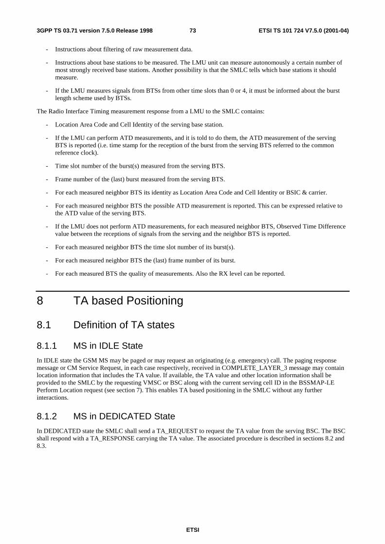
ETSI
ETSI TS 101 724 V7.5.0 (2001-04)733GPP TS 03.71 version 7.5.0 Release 1998
- Instructions about filtering of raw measurement data.
- Instructions about base stations to be measured. The LMU unit can measure autonomously a certain number of most strongly received base stations. Another possibility is that the SMLC tells which base stations it should measure.
- If the LMU measures signals from BTSs from other time slots than 0 or 4, it must be informed about the burst length scheme used by BTSs.
The Radio Interface Timing measurement response from a LMU to the SMLC contains:
- Location Area Code and Cell Identity of the serving base station.
- If the LMU can perform ATD measurements, and it is told to do them, the ATD measurement of the serving BTS is reported (i.e. time stamp for the reception of the burst from the serving BTS referred to the common reference clock).
- Time slot number of the burst(s) measured from the serving BTS.
- Frame number of the (last) burst measured from the serving BTS.
- For each measured neighbor BTS its identity as Location Area Code and Cell Identity or BSIC & carrier.
- For each measured neighbor BTS the possible ATD measurement is reported. This can be expressed relative to the ATD value of the serving BTS.
- If the LMU does not perform ATD measurements, for each measured neighbor BTS, Observed Time Difference value between the receptions of signals from the serving and the neighbor BTS is reported.
- For each measured neighbor BTS the time slot number of its burst(s).
- For each measured neighbor BTS the (last) frame number of its burst.
- For each measured BTS the quality of measurements. Also the RX level can be reported.
8 TA based Positioning
8.1 Definition of TA states
8.1.1 MS in IDLE State
In IDLE state the GSM MS may be paged or may request an originating (e.g. emergency) call. The paging response message or CM Service Request, in each case respectively, received in COMPLETE_LAYER_3 message may contain location information that includes the TA value. If available, the TA value and other location information shall be provided to the SMLC by the requesting VMSC or BSC along with the current serving cell ID in the BSSMAP-LE Perform Location request (see section 7). This enables TA based positioning in the SMLC without any further interactions.
8.1.2 MS in DEDICATED State
In DEDICATED state the SMLC shall send a TA_REQUEST to request the TA value from the serving BSC. The BSC shall respond with a TA_RESPONSE carrying the TA value. The associated procedure is described in sections 8.2 and 8.3.
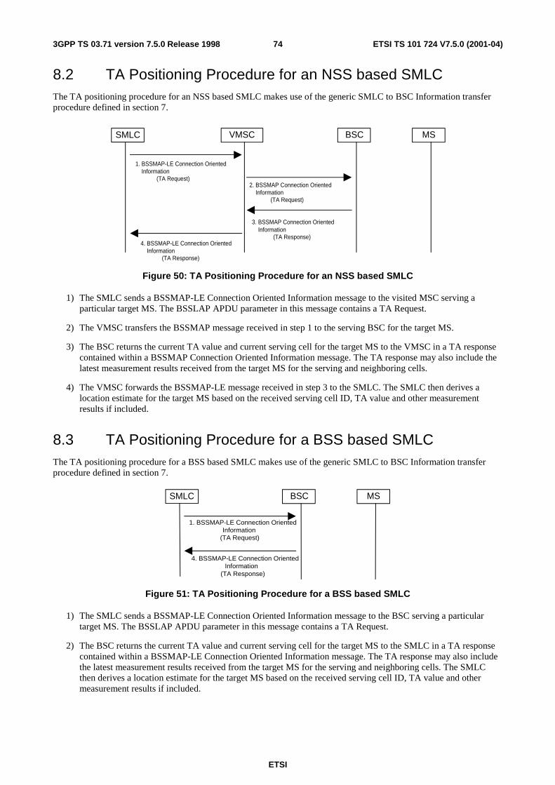
ETSI
ETSI TS 101 724 V7.5.0 (2001-04)743GPP TS 03.71 version 7.5.0 Release 1998
8.2 TA Positioning Procedure for an NSS based SMLC The TA positioning procedure for an NSS based SMLC makes use of the generic SMLC to BSC Information transfer procedure defined in section 7.
MSBSCSMLC VMSC
1. BSSMAP-LE Connection Oriented Information
(TA Request)2. BSSMAP Connection Oriented Information
(TA Request)
3. BSSMAP Connection Oriented Information
(TA Response)4. BSSMAP-LE Connection Oriented Information
(TA Response)
Figure 50: TA Positioning Procedure for an NSS based SMLC
1) The SMLC sends a BSSMAP-LE Connection Oriented Information message to the visited MSC serving a particular target MS. The BSSLAP APDU parameter in this message contains a TA Request.
2) The VMSC transfers the BSSMAP message received in step 1 to the serving BSC for the target MS.
3) The BSC returns the current TA value and current serving cell for the target MS to the VMSC in a TA response contained within a BSSMAP Connection Oriented Information message. The TA response may also include the latest measurement results received from the target MS for the serving and neighboring cells.
4) The VMSC forwards the BSSMAP-LE message received in step 3 to the SMLC. The SMLC then derives a location estimate for the target MS based on the received serving cell ID, TA value and other measurement results if included.
8.3 TA Positioning Procedure for a BSS based SMLC The TA positioning procedure for a BSS based SMLC makes use of the generic SMLC to BSC Information transfer procedure defined in section 7.
MSBSCSMLC
1. BSSMAP-LE Connection OrientedInformation
(TA Request)
4. BSSMAP-LE Connection OrientedInformation
(TA Response)
Figure 51: TA Positioning Procedure for a BSS based SMLC
1) The SMLC sends a BSSMAP-LE Connection Oriented Information message to the BSC serving a particular target MS. The BSSLAP APDU parameter in this message contains a TA Request.
2) The BSC returns the current TA value and current serving cell for the target MS to the SMLC in a TA response contained within a BSSMAP-LE Connection Oriented Information message. The TA response may also include the latest measurement results received from the target MS for the serving and neighboring cells. The SMLC then derives a location estimate for the target MS based on the received serving cell ID, TA value and other measurement results if included.
ETSI
ETSI TS 101 724 V7.5.0 (2001-04)753GPP TS 03.71 version 7.5.0 Release 1998
8.4 Unsuccessful TA positioning procedure in BSC There are three messages defined to handle error scenarios during positioning procedure in BSC. The messages are 1) Reject, 2) Abort and 3) Reset . Please refer to GSM 8.71 for details.
After receiving the BSSLAP TA Request in BSC (message 2 in section 8.2 and message 1 in section 8.3), a Reject will be sent with proper cause value from BSC to SMLC in "BSSMAP Connection Oriented Information" if TA positioning cannot be performed in BSC at that time for reasons other than handover or another ongoing RR management procedure.
Between messages 2 and 3 (in section 8.2) and between messages 1 and 2 in section 8.3, an Abort or Reset is possible if the TA positioning cannot be done in BSC during that time. Reset is sent to SMLC to indicate when the positioning needs to be restarted after temporary interruption due to intra BSC HO or other intra-BSC RR management. Abort is used to indicate to SMLC the failure of the current TA positioning attempt (e.g. due to inter-BSC handover) and allowing a new one from application level.
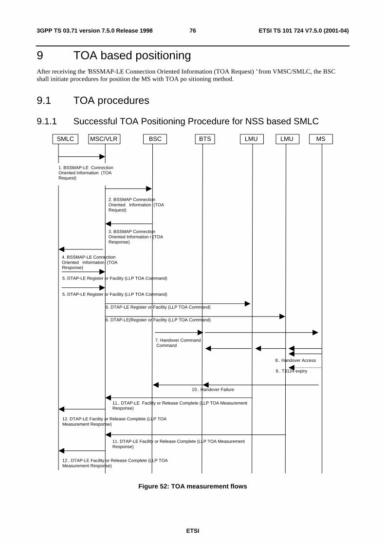
ETSI
ETSI TS 101 724 V7.5.0 (2001-04)763GPP TS 03.71 version 7.5.0 Release 1998
9 TOA based positioning After receiving the ’BSSMAP-LE Connection Oriented Information (TOA Request) ’ from VMSC/SMLC, the BSC shall initiate procedures for position the MS with TOA po sitioning method.
9.1 TOA procedures
9.1.1 Successful TOA Positioning Procedure for NSS based SMLC
MSLMUBSCMSC/VLR LMUSMLC BTS
6. DTAP-LE Register or Facility (LLP TOA Command)
8.. Handover Access
11.. DTAP-LE Facility or Release Complete (LLP TOA MeasurementResponse)
9.. T3124 expiry
4. BSSMAP-LE ConnectionOriented Information (TOAResponse)
7. Handover Command Command
10.. Handover Failure
12.. DTAP-LE Facility or Release Complete (LLP TOAMeasurement Response)
6. DTAP-LE(Register or Facility (LLP TOA Command)
11. DTAP-LE Facility or Release Complete (LLP TOA MeasurementResponse)
12. DTAP-LE Facility or Release Complete (LLP TOAMeasurement Response)
2. BSSMAP ConnectionOriented Information (TOARequest)
3. BSSMAP ConnectionOriented Information r (TOAResponse)
1. BSSMAP-LE ConnectionOriented Information (TOARequest)
5. DTAP-LE Register or Facility (LLP TOA Command)
5. DTAP-LE Register or Facility (LLP TOA Command)
Figure 52: TOA measurement flows
ETSI
ETSI TS 101 724 V7.5.0 (2001-04)773GPP TS 03.71 version 7.5.0 Release 1998
Positioning Preparations:
1. VMSC receives a ’BSSMAP-LE Connection Oriented Information (TOA Request)’ message from SMLC, which contains the BSC delta timer value and an indication of the preferred type of handover (intra-cell to same channel, intra-cell to new channel or inter-cell). The message also contains the cell ID and TDMA frame number of the serving cell, and depending on the preferred handover type, also contains the cell ID and TDMA frame number for candidate (maximum six) cells for positioning handover.
2. The MSC sends the BSSMAP Connection Oriented Information (TOA Request) ’ message to BSC with the same information received in step 1.
3. The BSC specifies the physical channel information (frequencies, hopping sequence, channel type, time slot for access burst etc.), cell ID, TA, measurement report, MS output power, and handover reference number in the ’BSSMAP Connection Oriented Information (TOA Response) ’ message to the VMSC. The BSC also starts the delta timer.
NOTE: If the BSC selects to use a different channel, this channel is reserved internally within the BSC, i.e. no additional signaling or delay is required. Based on the request information from SMLC, the BSC can choose between requesting an intra-cell handover (to same channel or to a new channel) or an inter-cell handover. If BSC decides to make an inter-cell handover the BSC selects a neighbor cell based on the measurement reports received from the MS (only neighbors for which the MS has been able to decode BSIC are possible to specify since the MS needs to know the timing of the target base station).
4. The VMSC forwards the information to the SMLC in ’BSSMAP-LE Connection Oriented Information (TOA Response) ’ message. SMLC uses this information for the configuration of the LMUs.
5. The SMLC selects which LMUs should measure and sends ’DTAP-LE Register or Facility (LLP TOA Command)’ messages for each of these LMUs to the MSC according to the procedure defined in section7.8.1.1. Each DTAP-LE message is targeted to one LMU and specifies Radio Frequency List, Hopping Sequence Information, HO reference number, BSIC, Starting Time, Measurement Options, Starting Time Uncertainty, GPS Time Stamping Request.
6. The MSC sends the DTAP message, which reaches the LMUs over the air interface. It has been assumed here that the DTAP connection is already established at this point (refer to section7.8.1.1).
Positioning Establishment:
7. At expiration of the delta timer (note 1), the mobile is instructed to perform non-synchronized handover from the current radio channel (e.g. SDCCH or TCH) to a specified traffic channel with HANDOVER COMMAND message. A TDMA frame number at which the sending of ACCESS burst should begin is specified.
8. The MS starts sending the access burst in HANDOVER ACCESS message. At the same time, configured LMUs measure the Time of Arrival of access bursts.
9. The MS continues to send the access bursts until the timer T3124 expires when the MS returns to the old channel.
10. The MS sends the HANDOVER FAILURE message to the BSC.
11. LMUs report their measurement results in a ’DTAP-LE Facility or Release Complete (LLP TOA Measurement Response)’ message to the VMSC.
12. The measurement results will be forwarded to the SMLC as a ’DTAP-LE Facility or Release Complete (LLP TOA Measurement Response)’ message with measured TOA, TOA quality estimate, and Used Time Stamping. SMLC shall keep track of the number of expected measurement results from LMUs in the network. If a location estimate satisfying the requested QoS was not successfully obtained, the SMLC may initiate another TOA location attempt by restarting the TOA procedure at step 1.
NOTE 1: BSC starts the delta timer when received from the MSC in (2). The purpose of this timer is to allow enough time for MLC to initialize and configure all the LMUs for the TOA measurement. This timer value should be long enough for this task. When the BSC timer runs out, the BSC starts the handover process (step7).
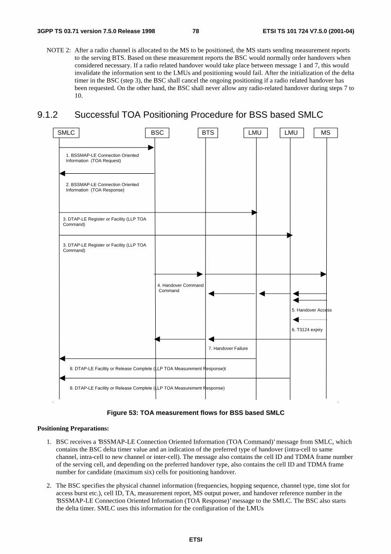
ETSI
ETSI TS 101 724 V7.5.0 (2001-04)783GPP TS 03.71 version 7.5.0 Release 1998
NOTE 2: After a radio channel is allocated to the MS to be positioned, the MS starts sending measurement reports to the serving BTS. Based on these measurement reports the BSC would normally order handovers when considered necessary. If a radio related handover would take place between message 1 and 7, this would invalidate the information sent to the LMUs and positioning would fail. After the initialization of the delta timer in the BSC (step 3), the BSC shall cancel the ongoing positioning if a radio related handover has been requested. On the other hand, the BSC shall never allow any radio-related handover during steps 7 to 10.
9.1.2 Successful TOA Positioning Procedure for BSS based SMLC
MSLMUBSC LMUSMLC BTS
3. DTAP-LE Register or Facility (LLP TOACommand)
5. Handover Access
8. DTAP-LE Facility or Release Complete (LLP TOA Measurement Response)t
6. T3124 expiry
4. Handover Command Command
7. Handover Failure
3. DTAP-LE Register or Facility (LLP TOACommand)
8. DTAP-LE Facility or Release Complete (LLP TOA Measurement Response)
1. BSSMAP-LE Connection OrientedInformation (TOA Request)
2. BSSMAP-LE Connection OrientedInformation (TOA Response)
Figure 53: TOA measurement flows for BSS based SMLC
Positioning Preparations:
1. BSC receives a ’BSSMAP-LE Connection Oriented Information (TOA Command)’ message from SMLC, which contains the BSC delta timer value and an indication of the preferred type of handover (intra-cell to same channel, intra-cell to new channel or inter-cell). The message also contains the cell ID and TDMA frame number of the serving cell, and depending on the preferred handover type, also contains the cell ID and TDMA frame number for candidate (maximum six) cells for positioning handover.
2. The BSC specifies the physical channel information (frequencies, hopping sequence, channel type, time slot for access burst etc.), cell ID, TA, measurement report, MS output power, and handover reference number in the ’BSSMAP-LE Connection Oriented Information (TOA Response)’ message to the SMLC. The BSC also starts the delta timer. SMLC uses this information for the configuration of the LMUs
ETSI
ETSI TS 101 724 V7.5.0 (2001-04)793GPP TS 03.71 version 7.5.0 Release 1998
NOTE: If the BSC selects to use a different channel, this channel is reserved internally within the BSC, i.e. no additional signaling or delay is required. Based on the request information from SMLC, the BSC can choose between requesting an intra-cell handover (to same channel or to a new channel) or an inter-cell handover. If BSC decides to make an inter-cell handover the BSC selects a neighbor cell based on the measurement reports received from the MS (only neighbors for which the MS has been able to decode BSIC are possible to specify since the MS needs to know the timing of the target base station).
3. The SMLC selects which LMUs should measure and sends ’DTAP-LE Resister or Facility (LLP TOA Command)’ messages for each of these LMUs according to the procedure defined in section 7.8.4.1Each LCS Information Request message is targeted to one LMU and specifies Radio Frequency List, Hopping Sequence Information, HO reference number, BSIC, Starting Time, Measurement Options, Starting Time Uncertainty, GPS Time Stamping Request. It has been assumed here that the DTAP connection is already established at this point (refer to section 7.8.4.1).
Positioning Establishment:
4. At expiration of the delta timer (note 1), the mobile is instructed to perform non-synchronized handover from the current radio channel (e.g. SDCCH or TCH) to a specified traffic channel with HANDOVER COMMAND message. A TDMA frame number at which the sending of ACCESS burst should begin is specified.
5. The MS starts sending the access burst in HANDOVER ACCESS message. At the same time, configured LMUs measure the Time of Arrival of access bursts.
6. The MS continues to send the access bursts until the timer T3124 expires when the MS returns to the old channel.
7. The MS sends the HANDOVER FAILURE message to the BSC.
8. The measurement results will be forwarded to the SMLC as a ’DTAP-LE Facility or Release Complete (LLP TOA Measurement Response)’ LCS Information Response message with measured TOA, TOA quality estimate, and Used Time Stamping. SMLC shall keep track of the number of expected measurement results from LMUs in the network.
NOTE 1: BSC starts the delta timer when received from the SMLC in (1). The purpose of this timer is to allow enough time for SMLC to initialize and configure all the LMUs for the TOA measurement. This timer value should be long enough for this task. When the BSC timer runs out, the BSC starts the handover process (step 4).
NOTE 2: After a radio channel is allocated to the MS to be positioned, the MS starts sending measurement reports to the serving BTS. Based on these measurement reports the BSC would normally order handovers when considered necessary. If a radio related handover would take place between message 1 and 4, this would invalidate the information sent to the LMUs and positioning would fail. After the initialization of the delta timer in the BSC (step 2), the BSC shall cancel the ongoing positioning if a radio related handover has been requested. On the other hand, the BSC shall never allow any radio-related handover during steps 4 to 7.
9.1.3 Successful TOA positioning procedure in BSC
There are three messages defined to handle error scenarios during positioning procedure in BSC. The messages are 1) Reject, 2) Abort and 3) Reset . Please refer to GSM 8.71 for details.
After receiving the BSSLAP TOA Command in BSC (message 2 in section 9.1.1 and message 1 in section 9.1.2), a Reject will be sent with proper cause value from BSC to SMLC in "BSSMAP Location Information Report" if TOA positioning cannot be performed in BSC at that time for reasons other than handover or another ongoing RR management procedure.
Between messages 3 and 7 in section 9.1.1 and between messages 2 and 4 in section 9.1.2 (i.e the duration of delta timer in the BSC), an Abort or Reset is possible if the TOA positioning can not be done in BSC during that time. Reset is sent to SMLC to indicate when the positioning needs to be restarted after temporary interruption due to an intra BSC HO or other intra-BSC RR management procedure. If the Handover Complete or Handover Failure is not received before the delta timer expires, Abort may be sent at the expiration of delta timer from BSC to SMLC. Abort is used to indicate to SMLC the failure of the current TOA positioning attempt (e.g. due to inter-BSC handover) and allowing a new one from application level.
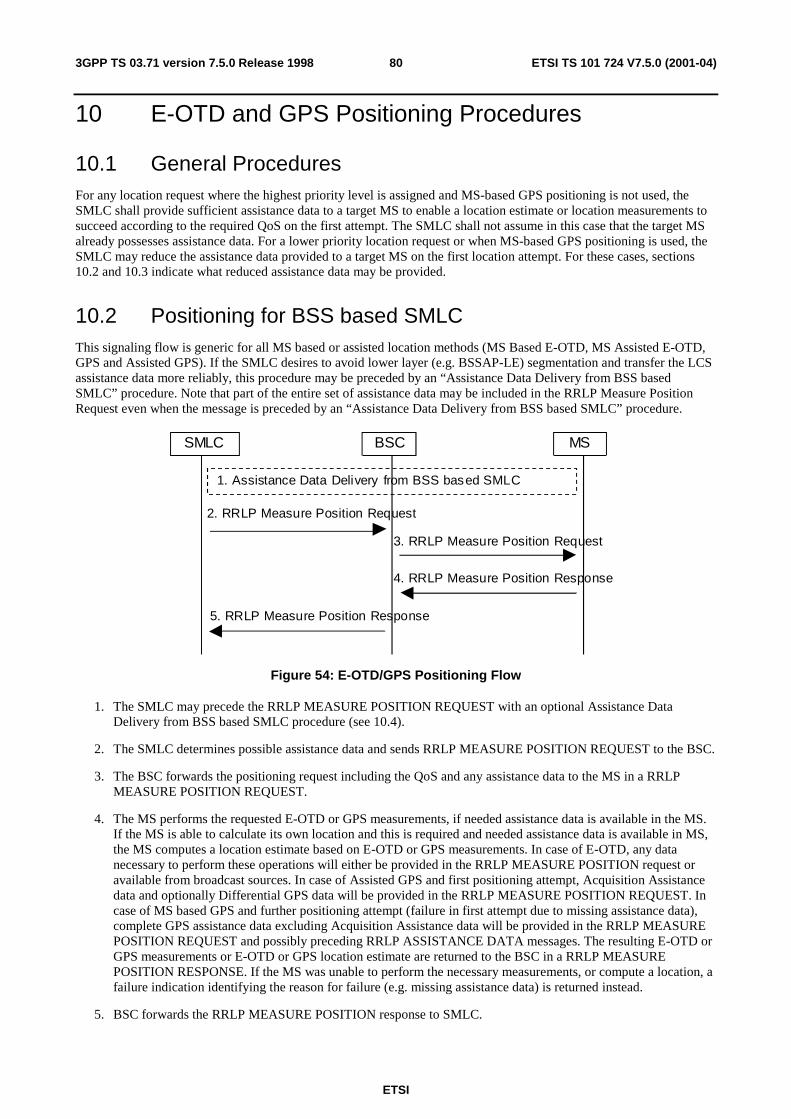
ETSI
ETSI TS 101 724 V7.5.0 (2001-04)803GPP TS 03.71 version 7.5.0 Release 1998
10 E-OTD and GPS Positioning Procedures
10.1 General Procedures For any location request where the highest priority level is assigned and MS-based GPS positioning is not used, the SMLC shall provide sufficient assistance data to a target MS to enable a location estimate or location measurements to succeed according to the required QoS on the first attempt. The SMLC shall not assume in this case that the target MS already possesses assistance data. For a lower priority location request or when MS-based GPS positioning is used, the SMLC may reduce the assistance data provided to a target MS on the first location attempt. For these cases, sections 10.2 and 10.3 indicate what reduced assistance data may be provided.
10.2 Positioning for BSS based SMLC This signaling flow is generic for all MS based or assisted location methods (MS Based E-OTD, MS Assisted E-OTD, GPS and Assisted GPS). If the SMLC desires to avoid lower layer (e.g. BSSAP-LE) segmentation and transfer the LCS assistance data more reliably, this procedure may be preceded by an “Assistance Data Delivery from BSS based SMLC” procedure. Note that part of the entire set of assistance data may be included in the RRLP Measure Position Request even when the message is preceded by an “Assistance Data Delivery from BSS based SMLC” procedure.
MSBSCSMLC
2. RRLP Measure Position Request
3. RRLP Measure Position Request
4. RRLP Measure Position Response
5. RRLP Measure Position Response
1. Assistance Data Delivery from BSS based SMLC
Figure 54: E-OTD/GPS Positioning Flow
1. The SMLC may precede the RRLP MEASURE POSITION REQUEST with an optional Assistance Data Delivery from BSS based SMLC procedure (see 10.4).
2. The SMLC determines possible assistance data and sends RRLP MEASURE POSITION REQUEST to the BSC.
3. The BSC forwards the positioning request including the QoS and any assistance data to the MS in a RRLP MEASURE POSITION REQUEST.
4. The MS performs the requested E-OTD or GPS measurements, if needed assistance data is available in the MS. If the MS is able to calculate its own location and this is required and needed assistance data is available in MS, the MS computes a location estimate based on E-OTD or GPS measurements. In case of E-OTD, any data necessary to perform these operations will either be provided in the RRLP MEASURE POSITION request or available from broadcast sources. In case of Assisted GPS and first positioning attempt, Acquisition Assistance data and optionally Differential GPS data will be provided in the RRLP MEASURE POSITION REQUEST. In case of MS based GPS and further positioning attempt (failure in first attempt due to missing assistance data), complete GPS assistance data excluding Acquisition Assistance data will be provided in the RRLP MEASURE POSITION REQUEST and possibly preceding RRLP ASSISTANCE DATA messages. The resulting E-OTD or GPS measurements or E-OTD or GPS location estimate are returned to the BSC in a RRLP MEASURE POSITION RESPONSE. If the MS was unable to perform the necessary measurements, or compute a location, a failure indication identifying the reason for failure (e.g. missing assistance data) is returned instead.
5. BSC forwards the RRLP MEASURE POSITION response to SMLC.
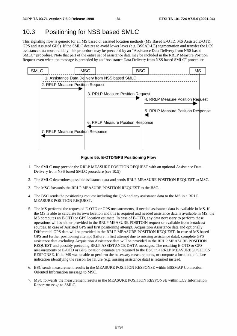
ETSI
ETSI TS 101 724 V7.5.0 (2001-04)813GPP TS 03.71 version 7.5.0 Release 1998
10.3 Positioning for NSS based SMLC This signaling flow is generic for all MS based or assisted location methods (MS Based E-OTD, MS Assisted E-OTD, GPS and Assisted GPS). If the SMLC desires to avoid lower layer (e.g. BSSAP-LE) segmentation and transfer the LCS assistance data more reliably, this procedure may be preceded by an “Assistance Data Delivery from NSS based SMLC” procedure. Note that part of the entire set of assistance data may be included in the RRLP Measure Position Request even when the message is preceded by an “Assistance Data Delivery from NSS based SMLC” procedure.
4. RRLP Measure Position Request
5. RRLP Measure Position Response
6. RRLP Measure Position Response
MSBSCMSCSMLC
3. RRLP Measure Position Request
2. RRLP Measure Position Request
7. RRLP Measure Position Response
1. Assistance Data Delivery from NSS based SMLC
Figure 55: E-OTD/GPS Positioning Flow
1. The SMLC may precede the RRLP MEASURE POSITION REQUEST with an optional Assistance Data Delivery from NSS based SMLC procedure (see 10.5).
2. The SMLC determines possible assistance data and sends RRLP MEASURE POSITION REQUEST to MSC.
3. The MSC forwards the RRLP MEASURE POSITION REQUEST to the BSC.
4. The BSC sends the positioning request including the QoS and any assistance data to the MS in a RRLP MEASURE POSITION REQUEST.
5. The MS performs the requested E-OTD or GPS measurements, if needed assistance data is available in MS. If the MS is able to calculate its own location and this is required and needed assistance data is available in MS, the MS computes an E-OTD or GPS location estimate. In case of E-OTD, any data necessary to perform these operations will be either provided in the RRLP MEASURE POSITOIN request or available from broadcast sources. In case of Assisted GPS and first positioning attempt, Acquisition Assistance data and optionally Differential GPS data will be provided in the RRLP MEASURE POSITION REQUEST. In case of MS based GPS and further positioning attempt (failure in first attempt due to missing assistance data), complete GPS assistance data excluding Acquisition Assistance data will be provided in the RRLP MEASURE POSITION REQUEST and possibly preceding RRLP ASSISTANCE DATA messages. The resulting E-OTD or GPS measurements or E-OTD or GPS location estimate are returned to the BSC in a RRLP MEASURE POSITION RESPONSE. If the MS was unable to perform the necessary measurements, or compute a location, a failure indication identifying the reason for failure (e.g. missing assistance data) is returned instead.
6. BSC sends measurement results in the MEASURE POSITION RESPONSE within BSSMAP Connection Oriented Information message to MSC.
7. MSC forwards the measurement results in the MEASURE POSITION RESPONSE within LCS Information Report message to SMLC.
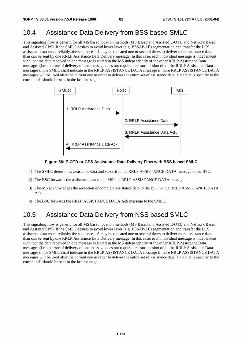
ETSI
ETSI TS 101 724 V7.5.0 (2001-04)823GPP TS 03.71 version 7.5.0 Release 1998
10.4 Assistance Data Delivery from BSS based SMLC This signaling flow is generic for all MS based location methods (MS Based and Assisted E-OTD and Network Based and Assisted GPS). If the SMLC desires to avoid lower layer (e.g. BSSAP-LE) segmentation and transfer the LCS assistance data more reliably, the sequence 1-4 may be repeated one or several times to deliver more assistance data than can be sent by one RRLP Assistance Data Delivery message. In this case, each individual message is independent such that the data received in one message is stored in the MS independently of the other RRLP Assistance Data messages (i.e. an error of delivery of one message does not require a retransmission of all the RRLP Assistance Data messages). The SMLC shall indicate in the RRLP ASSISTANCE DATA message if more RRLP ASSISTANCE DATA messages will be used after the current one in order to deliver the entire set of assistance data. Data that is specific to the current cell should be sent in the last message.
MSBSCSMLC
1. RRLP Assistance Data
2. RRLP Assistance Data
3. RRLP Assistance Data Ack.
4. RRLP Assistance Data Ack.
Figure 56: E-OTD or GPS Assistance Data Delivery Flow with BSS based SMLC
1) The SMLC determines assistance data and sends it in the RRLP ASSISTANCE DATA message to the BSC.
2) The BSC forwards the assistance data to the MS in a RRLP ASSISTANCE DATA message.
3) The MS acknowledges the reception of complete assistance data to the BSC with a RRLP ASSISTANCE DATA Ack.
4) The BSC forwards the RRLP ASSISTANCE DATA Ack message to the SMLC.
10.5 Assistance Data Delivery from NSS based SMLC This signaling flow is generic for all MS based location methods (MS Based and Assisted E-OTD and Network Based and Assisted GPS). If the SMLC desires to avoid lower layer (e.g. BSSAP-LE) segmentation and transfer the LCS assistance data more reliably, the sequence 1-6 may be repeated one or several times to deliver more assistance data than can be sent by one RRLP Assistance Data Delivery message. In this case, each individual message is independent such that the data received in one message is stored in the MS independently of the other RRLP Assistance Data messages (i.e. an error of delivery of one message does not require a retransmission of all the RRLP Assistance Data messages). The SMLC shall indicate in the RRLP ASSISTANCE DATA message if more RRLP ASSISTANCE DATA messages will be used after the current one in order to deliver the entire set of assistance data. Data that is specific to the current cell should be sent in the last message.
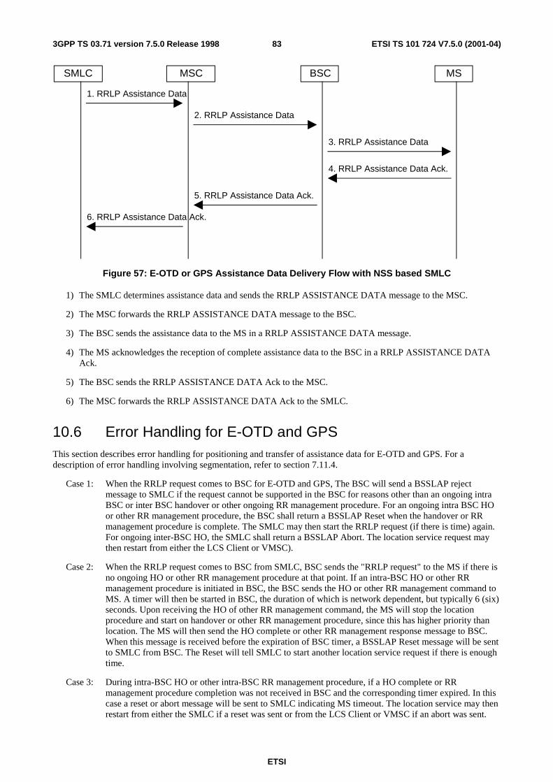
ETSI
ETSI TS 101 724 V7.5.0 (2001-04)833GPP TS 03.71 version 7.5.0 Release 1998
MSBSCMSC
2. RRLP Assistance Data
3. RRLP Assistance Data
4. RRLP Assistance Data Ack.
5. RRLP Assistance Data Ack.
SMLC
1. RRLP Assistance Data
6. RRLP Assistance Data Ack.
Figure 57: E-OTD or GPS Assistance Data Delivery Flow with NSS based SMLC
1) The SMLC determines assistance data and sends the RRLP ASSISTANCE DATA message to the MSC.
2) The MSC forwards the RRLP ASSISTANCE DATA message to the BSC.
3) The BSC sends the assistance data to the MS in a RRLP ASSISTANCE DATA message.
4) The MS acknowledges the reception of complete assistance data to the BSC in a RRLP ASSISTANCE DATA Ack.
5) The BSC sends the RRLP ASSISTANCE DATA Ack to the MSC.
6) The MSC forwards the RRLP ASSISTANCE DATA Ack to the SMLC.
10.6 Error Handling for E-OTD and GPS This section describes error handling for positioning and transfer of assistance data for E-OTD and GPS. For a description of error handling involving segmentation, refer to section 7.11.4.
Case 1: When the RRLP request comes to BSC for E-OTD and GPS, The BSC will send a BSSLAP reject message to SMLC if the request cannot be supported in the BSC for reasons other than an ongoing intra BSC or inter BSC handover or other ongoing RR management procedure. For an ongoing intra BSC HO or other RR management procedure, the BSC shall return a BSSLAP Reset when the handover or RR management procedure is complete. The SMLC may then start the RRLP request (if there is time) again. For ongoing inter-BSC HO, the SMLC shall return a BSSLAP Abort. The location service request may then restart from either the LCS Client or VMSC).
Case 2: When the RRLP request comes to BSC from SMLC, BSC sends the "RRLP request" to the MS if there is no ongoing HO or other RR management procedure at that point. If an intra-BSC HO or other RR management procedure is initiated in BSC, the BSC sends the HO or other RR management command to MS. A timer will then be started in BSC, the duration of which is network dependent, but typically 6 (six) seconds. Upon receiving the HO of other RR management command, the MS will stop the location procedure and start on handover or other RR management procedure, since this has higher priority than location. The MS will then send the HO complete or other RR management response message to BSC. When this message is received before the expiration of BSC timer, a BSSLAP Reset message will be sent to SMLC from BSC. The Reset will tell SMLC to start another location service request if there is enough time.
Case 3: During intra-BSC HO or other intra-BSC RR management procedure, if a HO complete or RR management procedure completion was not received in BSC and the corresponding timer expired. In this case a reset or abort message will be sent to SMLC indicating MS timeout. The location service may then restart from either the SMLC if a reset was sent or from the LCS Client or VMSC if an abort was sent.

ETSI
ETSI TS 101 724 V7.5.0 (2001-04)843GPP TS 03.71 version 7.5.0 Release 1998
Case 4: If an inter-BSC (or inter-MSC) handover is needed during a location procedure or if the BSC times out on an RRLP response from the target MS, the BSC shall send a BSSLAP Abort to the SMLC. The location service attempt may then be restarted from either the LCS Client or VMSC.
10.6.1 NSS based SMLC
X Inter-BSC handover required or BSCtimeout on RRLP response from the MS
7. Abort (Case 4)
6. Abort (Case 4)
MSBSCMSC
2. RRLP Request
3’. RRLP Request
SMLC
1. RRLP Request
4. HO Command
5. HO Complete
Intra-BSC HandoverInitiated, T3103started X
6. Reset (Case 2)
7. Reset (Case 2)
X T3103 Expired, HO complete not received
OR
6’. Reset or Abort (Case 3)
5’. Reset or Abort (Case 3)OR
OR
OR
3. Reject or Reset or Abort (Case 1)4. Reject or Reset orAbort (Case 1)
OROR
Figure 58
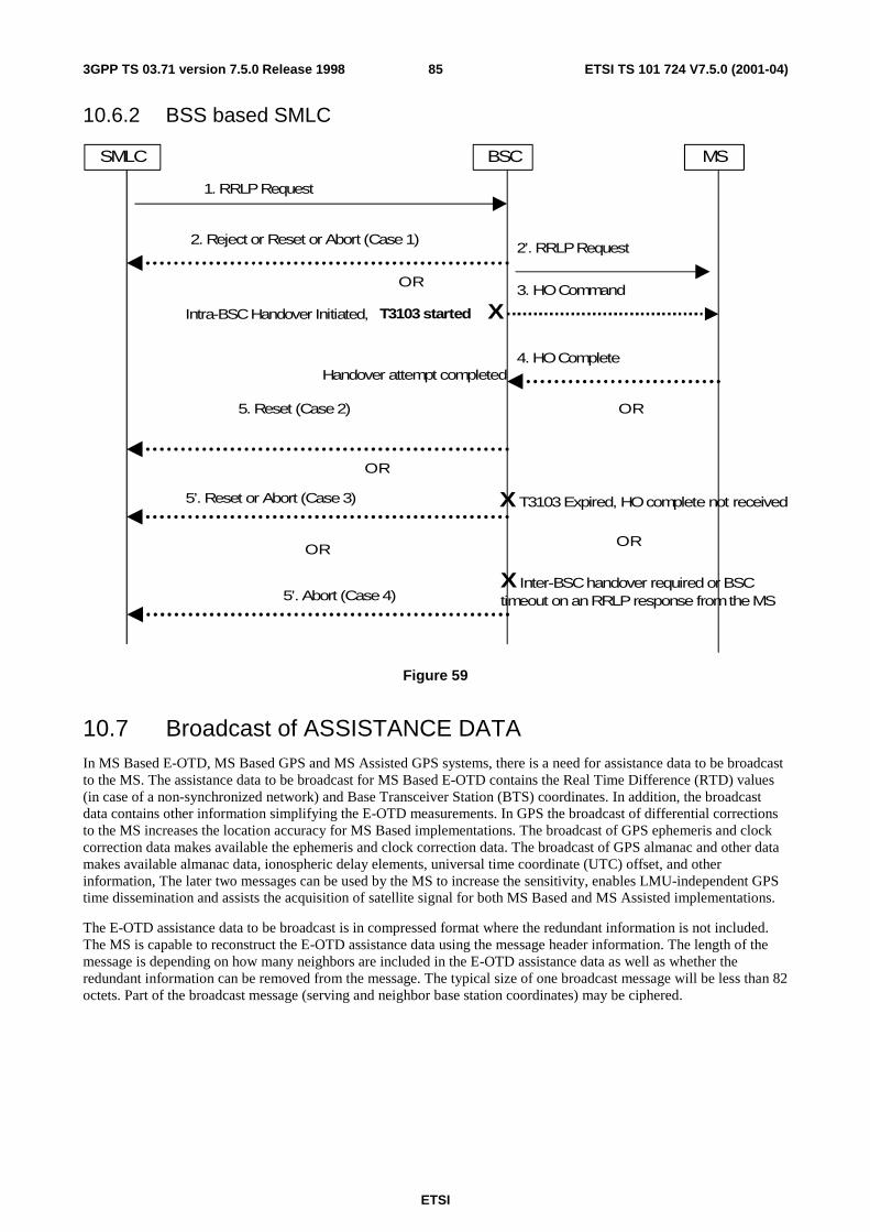
ETSI
ETSI TS 101 724 V7.5.0 (2001-04)853GPP TS 03.71 version 7.5.0 Release 1998
10.6.2 BSS based SMLC
MSBSC
2’. RRLP Request
SMLC
1. RRLP Request
3. HO Command
4. HO Complete
Intra-BSC Handover Initiated, T3103 started X
5. Reset (Case 2)
Handover attempt completed
X T3103 Expired, HO complete not received
OR
5’. Reset or Abort (Case 3)
OR
OR
2. Reject or Reset or Abort (Case 1)
X Inter-BSC handover required or BSCtimeout on an RRLP response from the MS5’. Abort (Case 4)
OROR
Figure 59
10.7 Broadcast of ASSISTANCE DATA In MS Based E-OTD, MS Based GPS and MS Assisted GPS systems, there is a need for assistance data to be broadcast to the MS. The assistance data to be broadcast for MS Based E-OTD contains the Real Time Difference (RTD) values (in case of a non-synchronized network) and Base Transceiver Station (BTS) coordinates. In addition, the broadcast data contains other information simplifying the E-OTD measurements. In GPS the broadcast of differential corrections to the MS increases the location accuracy for MS Based implementations. The broadcast of GPS ephemeris and clock correction data makes available the ephemeris and clock correction data. The broadcast of GPS almanac and other data makes available almanac data, ionospheric delay elements, universal time coordinate (UTC) offset, and other information, The later two messages can be used by the MS to increase the sensitivity, enables LMU-independent GPS time dissemination and assists the acquisition of satellite signal for both MS Based and MS Assisted implementations.
The E-OTD assistance data to be broadcast is in compressed format where the redundant information is not included. The MS is capable to reconstruct the E-OTD assistance data using the message header information. The length of the message is depending on how many neighbors are included in the E-OTD assistance data as well as whether the redundant information can be removed from the message. The typical size of one broadcast message will be less than 82 octets. Part of the broadcast message (serving and neighbor base station coordinates) may be ciphered.
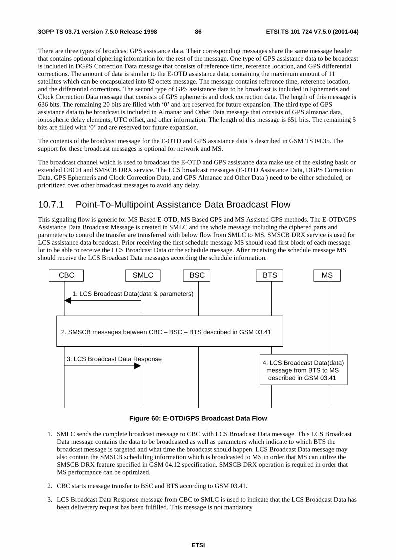
ETSI
ETSI TS 101 724 V7.5.0 (2001-04)863GPP TS 03.71 version 7.5.0 Release 1998
There are three types of broadcast GPS assistance data. Their corresponding messages share the same message header that contains optional ciphering information for the rest of the message. One type of GPS assistance data to be broadcast is included in DGPS Correction Data message that consists of reference time, reference location, and GPS differential corrections. The amount of data is similar to the E-OTD assistance data, containing the maximum amount of 11 satellites which can be encapsulated into 82 octets message. The message contains reference time, reference location, and the differential corrections. The second type of GPS assistance data to be broadcast is included in Ephemeris and Clock Correction Data message that consists of GPS ephemeris and clock correction data. The length of this message is 636 bits. The remaining 20 bits are filled with ‘0’ and are reserved for future expansion. The third type of GPS assistance data to be broadcast is included in Almanac and Other Data message that consists of GPS almanac data, ionospheric delay elements, UTC offset, and other information. The length of this message is 651 bits. The remaining 5 bits are filled with ‘0’ and are reserved for future expansion.
The contents of the broadcast message for the E-OTD and GPS assistance data is described in GSM TS 04.35. The support for these broadcast messages is optional for network and MS.
The broadcast channel which is used to broadcast the E-OTD and GPS assistance data make use of the existing basic or extended CBCH and SMSCB DRX service. The LCS broadcast messages (E-OTD Assistance Data, DGPS Correction Data, GPS Ephemeris and Clock Correction Data, and GPS Almanac and Other Data ) need to be either scheduled, or prioritized over other broadcast messages to avoid any delay.
10.7.1 Point-To-Multipoint Assistance Data Broadcast Flow
This signaling flow is generic for MS Based E-OTD, MS Based GPS and MS Assisted GPS methods. The E-OTD/GPS Assistance Data Broadcast Message is created in SMLC and the whole message including the ciphered parts and parameters to control the transfer are transferred with below flow from SMLC to MS. SMSCB DRX service is used for LCS assistance data broadcast. Prior receiving the first schedule message MS should read first block of each message lot to be able to receive the LCS Broadcast Data or the schedule message. After receiving the schedule message MS should receive the LCS Broadcast Data messages according the schedule information.
MSBSCCBC
1. LCS Broadcast Data(data & parameters)
SMLC BTS
3. LCS Broadcast Data Response
2. SMSCB messages between CBC – BSC – BTS described in GSM 03.41
4. LCS Broadcast Data(data)message from BTS to MSdescribed in GSM 03.41
Figure 60: E-OTD/GPS Broadcast Data Flow
1. SMLC sends the complete broadcast message to CBC with LCS Broadcast Data message. This LCS Broadcast Data message contains the data to be broadcasted as well as parameters which indicate to which BTS the broadcast message is targeted and what time the broadcast should happen. LCS Broadcast Data message may also contain the SMSCB scheduling information which is broadcasted to MS in order that MS can utilize the SMSCB DRX feature specified in GSM 04.12 specification. SMSCB DRX operation is required in order that MS performance can be optimized.
2. CBC starts message transfer to BSC and BTS according to GSM 03.41.
3. LCS Broadcast Data Response message from CBC to SMLC is used to indicate that the LCS Broadcast Data has been deliverery request has been fulfilled. This message is not mandatory
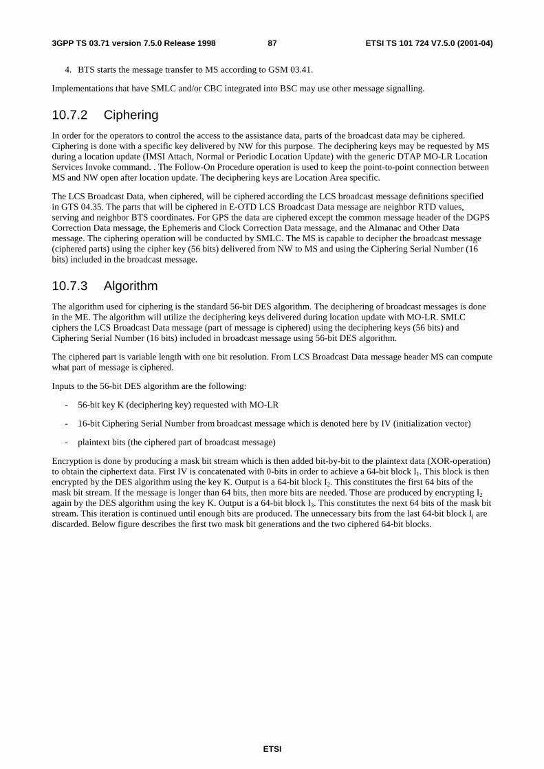
ETSI
ETSI TS 101 724 V7.5.0 (2001-04)873GPP TS 03.71 version 7.5.0 Release 1998
4. BTS starts the message transfer to MS according to GSM 03.41.
Implementations that have SMLC and/or CBC integrated into BSC may use other message signalling.
10.7.2 Ciphering
In order for the operators to control the access to the assistance data, parts of the broadcast data may be ciphered. Ciphering is done with a specific key delivered by NW for this purpose. The deciphering keys may be requested by MS during a location update (IMSI Attach, Normal or Periodic Location Update) with the generic DTAP MO-LR Location Services Invoke command. . The Follow-On Procedure operation is used to keep the point-to-point connection between MS and NW open after location update. The deciphering keys are Location Area specific.
The LCS Broadcast Data, when ciphered, will be ciphered according the LCS broadcast message definitions specified in GTS 04.35. The parts that will be ciphered in E-OTD LCS Broadcast Data message are neighbor RTD values, serving and neighbor BTS coordinates. For GPS the data are ciphered except the common message header of the DGPS Correction Data message, the Ephemeris and Clock Correction Data message, and the Almanac and Other Data message. The ciphering operation will be conducted by SMLC. The MS is capable to decipher the broadcast message (ciphered parts) using the cipher key (56 bits) delivered from NW to MS and using the Ciphering Serial Number (16 bits) included in the broadcast message.
10.7.3 Algorithm
The algorithm used for ciphering is the standard 56-bit DES algorithm. The deciphering of broadcast messages is done in the ME. The algorithm will utilize the deciphering keys delivered during location update with MO-LR. SMLC ciphers the LCS Broadcast Data message (part of message is ciphered) using the deciphering keys (56 bits) and Ciphering Serial Number (16 bits) included in broadcast message using 56-bit DES algorithm.
The ciphered part is variable length with one bit resolution. From LCS Broadcast Data message header MS can compute what part of message is ciphered.
Inputs to the 56-bit DES algorithm are the following:
- 56-bit key K (deciphering key) requested with MO-LR
- 16-bit Ciphering Serial Number from broadcast message which is denoted here by IV (initialization vector)
- plaintext bits (the ciphered part of broadcast message)
Encryption is done by producing a mask bit stream which is then added bit-by-bit to the plaintext data (XOR-operation) to obtain the ciphertext data. First IV is concatenated with 0-bits in order to achieve a 64-bit block I1. This block is then encrypted by the DES algorithm using the key K. Output is a 64-bit block I2. This constitutes the first 64 bits of the mask bit stream. If the message is longer than 64 bits, then more bits are needed. Those are produced by encrypting I2
again by the DES algorithm using the key K. Output is a 64-bit block I3. This constitutes the next 64 bits of the mask bit stream. This iteration is continued until enough bits are produced. The unnecessary bits from the last 64-bit block Ij are discarded. Below figure describes the first two mask bit generations and the two ciphered 64-bit blocks.
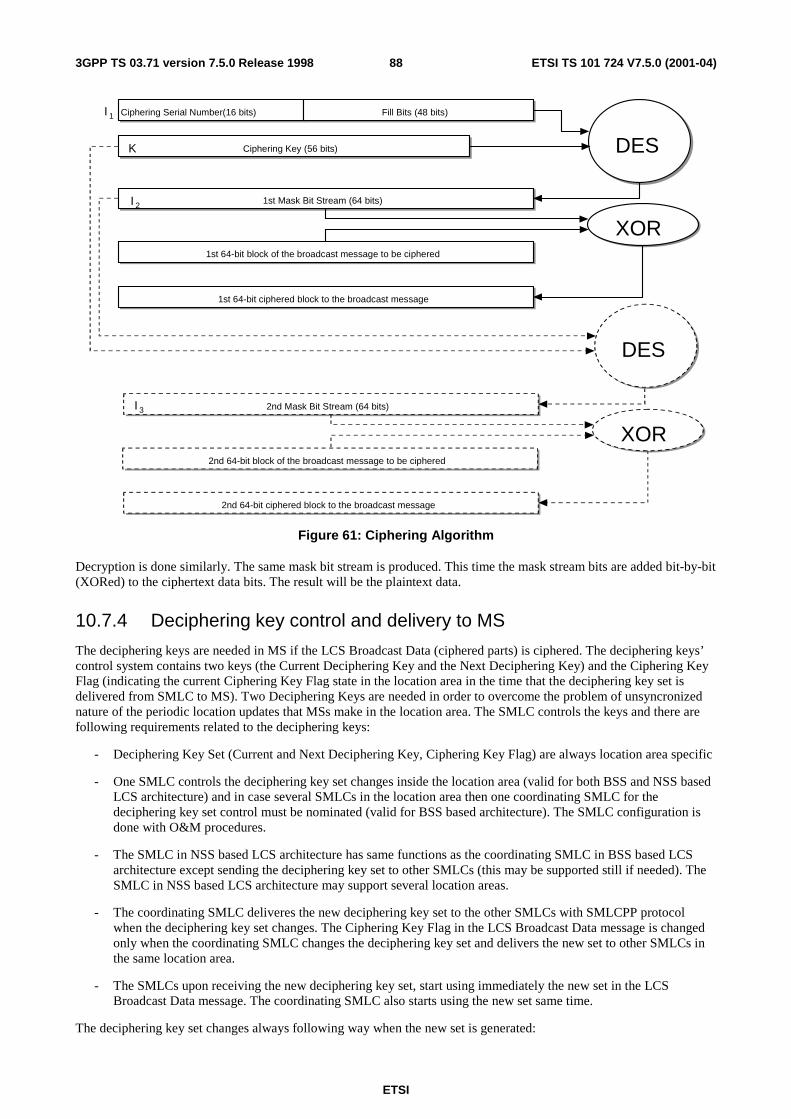
ETSI
ETSI TS 101 724 V7.5.0 (2001-04)883GPP TS 03.71 version 7.5.0 Release 1998
Message Code & Update Number(14 bits)Ciphering Serial Number(16 bits) Fill Bits (50 bits)Fill Bits (48 bits)I 1
DESDESCiphering Key (56 bits)Ciphering Key (56 bits)K
1st Mask Bit Stream (64 bits)1st Mask Bit Stream (64 bits)
1st 64-bit block of the broadcast message to be ciphered1st 64-bit block of the broadcast message to be ciphered
XORXOR
1st 64-bit ciphered block to the broadcast message1st 64-bit ciphered block to the broadcast message
DESDES
2nd Mask Bit Stream (64 bits)2nd Mask Bit Stream (64 bits)
XORXOR
2nd 64-bit ciphered block to the broadcast message2nd 64-bit ciphered block to the broadcast message
2nd 64-bit block of the broadcast message to be ciphered2nd 64-bit block of the broadcast message to be ciphered
I 3
I 2
Figure 61: Ciphering Algorithm
Decryption is done similarly. The same mask bit stream is produced. This time the mask stream bits are added bit-by-bit (XORed) to the ciphertext data bits. The result will be the plaintext data.
10.7.4 Deciphering key control and delivery to MS
The deciphering keys are needed in MS if the LCS Broadcast Data (ciphered parts) is ciphered. The deciphering keys’ control system contains two keys (the Current Deciphering Key and the Next Deciphering Key) and the Ciphering Key Flag (indicating the current Ciphering Key Flag state in the location area in the time that the deciphering key set is delivered from SMLC to MS). Two Deciphering Keys are needed in order to overcome the problem of unsyncronized nature of the periodic location updates that MSs make in the location area. The SMLC controls the keys and there are following requirements related to the deciphering keys:
- Deciphering Key Set (Current and Next Deciphering Key, Ciphering Key Flag) are always location area specific
- One SMLC controls the deciphering key set changes inside the location area (valid for both BSS and NSS based LCS architecture) and in case several SMLCs in the location area then one coordinating SMLC for the deciphering key set control must be nominated (valid for BSS based architecture). The SMLC configuration is done with O&M procedures.
- The SMLC in NSS based LCS architecture has same functions as the coordinating SMLC in BSS based LCS architecture except sending the deciphering key set to other SMLCs (this may be supported still if needed). The SMLC in NSS based LCS architecture may support several location areas.
- The coordinating SMLC deliveres the new deciphering key set to the other SMLCs with SMLCPP protocol when the deciphering key set changes. The Ciphering Key Flag in the LCS Broadcast Data message is changed only when the coordinating SMLC changes the deciphering key set and delivers the new set to other SMLCs in the same location area.
- The SMLCs upon receiving the new deciphering key set, start using immediately the new set in the LCS Broadcast Data message. The coordinating SMLC also starts using the new set same time.
The deciphering key set changes always following way when the new set is generated:
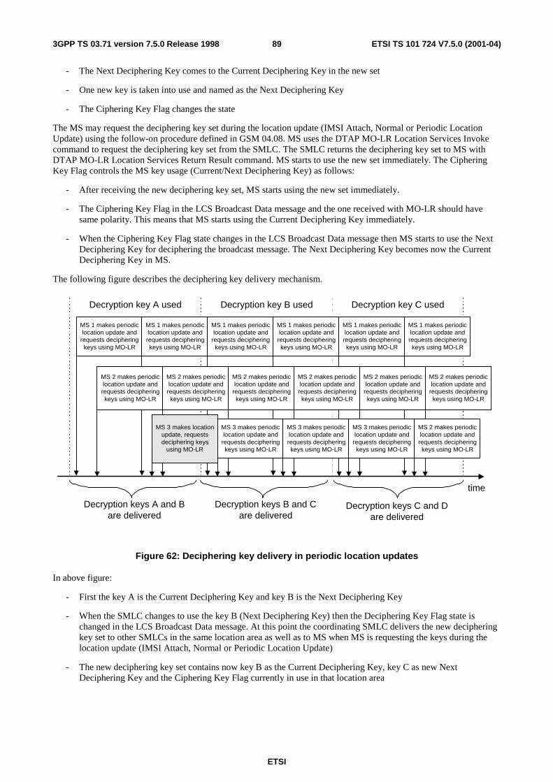
ETSI
ETSI TS 101 724 V7.5.0 (2001-04)893GPP TS 03.71 version 7.5.0 Release 1998
- The Next Deciphering Key comes to the Current Deciphering Key in the new set
- One new key is taken into use and named as the Next Deciphering Key
- The Ciphering Key Flag changes the state
The MS may request the deciphering key set during the location update (IMSI Attach, Normal or Periodic Location Update) using the follow-on procedure defined in GSM 04.08. MS uses the DTAP MO-LR Location Services Invoke command to request the deciphering key set from the SMLC. The SMLC returns the deciphering key set to MS with DTAP MO-LR Location Services Return Result command. MS starts to use the new set immediately. The Ciphering Key Flag controls the MS key usage (Current/Next Deciphering Key) as follows:
- After receiving the new deciphering key set, MS starts using the new set immediately.
- The Ciphering Key Flag in the LCS Broadcast Data message and the one received with MO-LR should have same polarity. This means that MS starts using the Current Deciphering Key immediately.
- When the Ciphering Key Flag state changes in the LCS Broadcast Data message then MS starts to use the Next Deciphering Key for deciphering the broadcast message. The Next Deciphering Key becomes now the Current Deciphering Key in MS.
The following figure describes the deciphering key delivery mechanism.
Decryption key A used Decryption key B used Decryption key C used
time
MS 3 makes locationupdate, requestsdeciphering keys
using MO-LR
Decryption keys B and Care delivered
Decryption keys C and Dare delivered
Decryption keys A and Bare delivered
MS 2 makes periodiclocation update andrequests decipheringkeys using MO-LR
MS 2 makes periodiclocation update andrequests decipheringkeys using MO-LR
MS 2 makes periodiclocation update and
requests decipheringkeys using MO-LR
MS 2 makes periodiclocation update andrequests decipheringkeys using MO-LR
MS 2 makes periodiclocation update and
requests decipheringkeys using MO-LR
MS 2 makes periodiclocation update and
requests decipheringkeys using MO-LR
MS 3 makes periodiclocation update andrequests decipheringkeys using MO-LR
MS 3 makes periodiclocation update andrequests decipheringkeys using MO-LR
MS 3 makes periodiclocation update and
requests decipheringkeys using MO-LR
MS 2 makes periodiclocation update andrequests decipheringkeys using MO-LR
MS 1 makes periodiclocation update and
requests decipheringkeys using MO-LR
MS 1 makes periodiclocation update andrequests decipheringkeys using MO-LR
MS 1 makes periodiclocation update and
requests decipheringkeys using MO-LR
MS 1 makes periodiclocation update andrequests decipheringkeys using MO-LR
MS 1 makes periodiclocation update andrequests decipheringkeys using MO-LR
MS 1 makes periodiclocation update andrequests decipheringkeys using MO-LR
Figure 62: Deciphering key delivery in periodic location updates
In above figure:
- First the key A is the Current Deciphering Key and key B is the Next Deciphering Key
- When the SMLC changes to use the key B (Next Deciphering Key) then the Deciphering Key Flag state is changed in the LCS Broadcast Data message. At this point the coordinating SMLC delivers the new deciphering key set to other SMLCs in the same location area as well as to MS when MS is requesting the keys during the location update (IMSI Attach, Normal or Periodic Location Update)
- The new deciphering key set contains now key B as the Current Deciphering Key, key C as new Next Deciphering Key and the Ciphering Key Flag currently in use in that location area
ETSI
ETSI TS 101 724 V7.5.0 (2001-04)903GPP TS 03.71 version 7.5.0 Release 1998
- When the SMLC changes to use the key C (Next Deciphering Key) then the Ciphering Key Flag state is changed in the LCS Broadcast Data message. At this point the coordinating SMLC delivers the new deciphering key set to other SMLCs in same location area as well as to MS when MS is requesting the new set during the location update (IMSI Attach, Normal or Periodic Location Update)
- The new deciphering key set contains now key C as the Current Deciphering Key, key D as new Next Deciphering Key and the Ciphering Key Flag currently in use in that location area
The process continues as above when the keys are changed . The lifetime of one key (Current/Next Ciphering Key) is minimum one periodic location update period used in the location area.
11 Position calculation functionality
11.1 TA For the TA once the cell-ID and TA value has been returned to the MLC, the MLC PCF should map this information into a standardized format suitable for the client. This may infer either just passing the received information in its current format or representing the area in some manner.
11.2 Time Of Arrival (TOA) Positioning mechanism For the TOA positioning mechanism once the cell-IDs, TOA values and TOA measurement quality information has been returned to the SMLC, the SMLC PCF should estimate the position of the MS based on this information and MLC prior knowledge of RTDs and LMU co-ordinates. The estimated MS position is then mapped and/or converted into a standardized format suitable for the requesting client.
11.3 Enhanced Observed Time Difference (E-OTD)
For the E-OTD positioning mechanism once the Cell IDs (or possibly in case of neighbor BTSs the Channel and BSIC information), TA value to the serving BTS, E-OTD values and E-OTD measurement quality information have been returned to the MLC, the MLC PCF should estimate the position of the MS based on this information and MLC prior knowledge of RTDs and BTS coordinates. The estimated MS position is then mapped and/or converted into a standardized format suitable for the requesting application.
11.4 Global Positioning System (GPS) positioning mechanism For the case where the PCF is in the GPS-equipped MS, the MS measures the phases of signals transmitted by the GPS satellites. Subsequently, the MS uses these measurements along with information describing the respective satellite positions to estimate its own position. The MS may choose to use assistance data available from within or outside of the GSM network during measurement and position computation, but this is not mandatory. The MS returns the position estimate to the MLC, along with an estimate of the position accuracy. The estimated MS position is then mapped and/or converted into a standardized format suitable for the requesting application.
For the case where the PCF is in the MLC, the MS measures the phases of signals transmitted by the GPS satellites. The MS may choose to use assistance data available from within or outside of the GSM network to aid the measurement process, but this is not mandatory. The MS returns the measurements and associated quality estimates to the MLC. The MLC uses these results plus the cell-ID (location) of the serving BTS, time-measurement results from the GEMU, and information describing the positions of the satellites measured by the MS to estimate the MS’s position. The estimated MS position is then mapped and/or converted into a standardized format suitable for the requesting application.
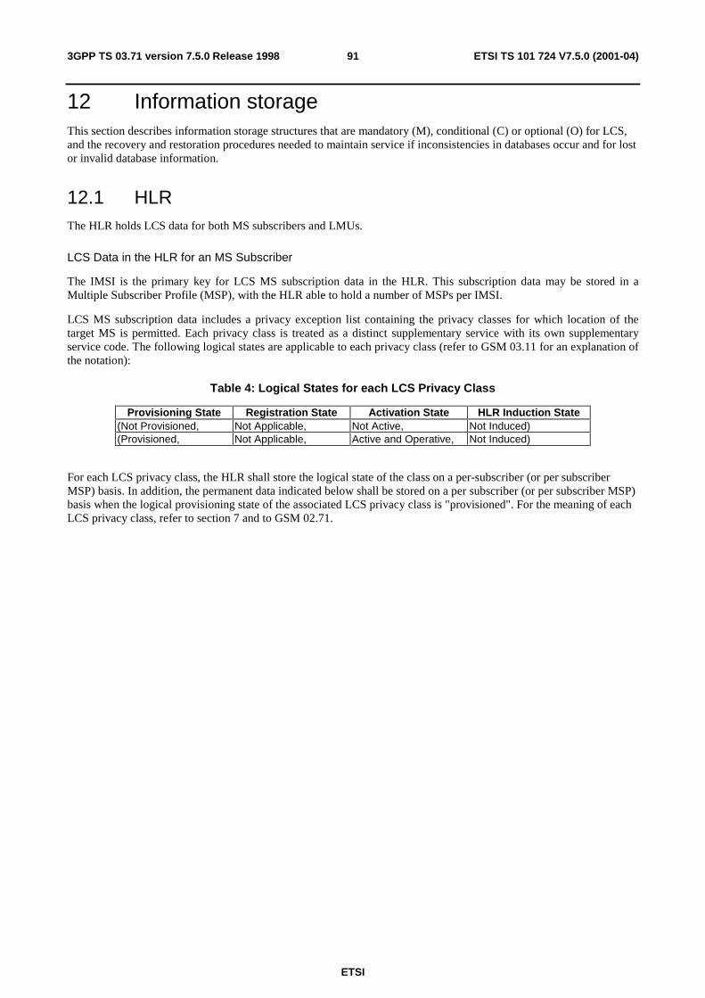
ETSI
ETSI TS 101 724 V7.5.0 (2001-04)913GPP TS 03.71 version 7.5.0 Release 1998
12 Information storage This section describes information storage structures that are mandatory (M), conditional (C) or optional (O) for LCS, and the recovery and restoration procedures needed to maintain service if inconsistencies in databases occur and for lost or invalid database information.
12.1 HLR The HLR holds LCS data for both MS subscribers and LMUs.
LCS Data in the HLR for an MS Subscriber
The IMSI is the primary key for LCS MS subscription data in the HLR. This subscription data may be stored in a Multiple Subscriber Profile (MSP), with the HLR able to hold a number of MSPs per IMSI.
LCS MS subscription data includes a privacy exception list containing the privacy classes for which location of the target MS is permitted. Each privacy class is treated as a distinct supplementary service with its own supplementary service code. The following logical states are applicable to each privacy class (refer to GSM 03.11 for an explanation of the notation):
Table 4: Logical States for each LCS Privacy Class
Provisioning State Registration State Activation State HLR Induction State (Not Provisioned, Not Applicable, Not Active, Not Induced) (Provisioned, Not Applicable, Active and Operative, Not Induced)
For each LCS privacy class, the HLR shall store the logical state of the class on a per-subscriber (or per subscriber MSP) basis. In addition, the permanent data indicated below shall be stored on a per subscriber (or per subscriber MSP) basis when the logical provisioning state of the associated LCS privacy class is "provisioned". For the meaning of each LCS privacy class, refer to section 7 and to GSM 02.71.
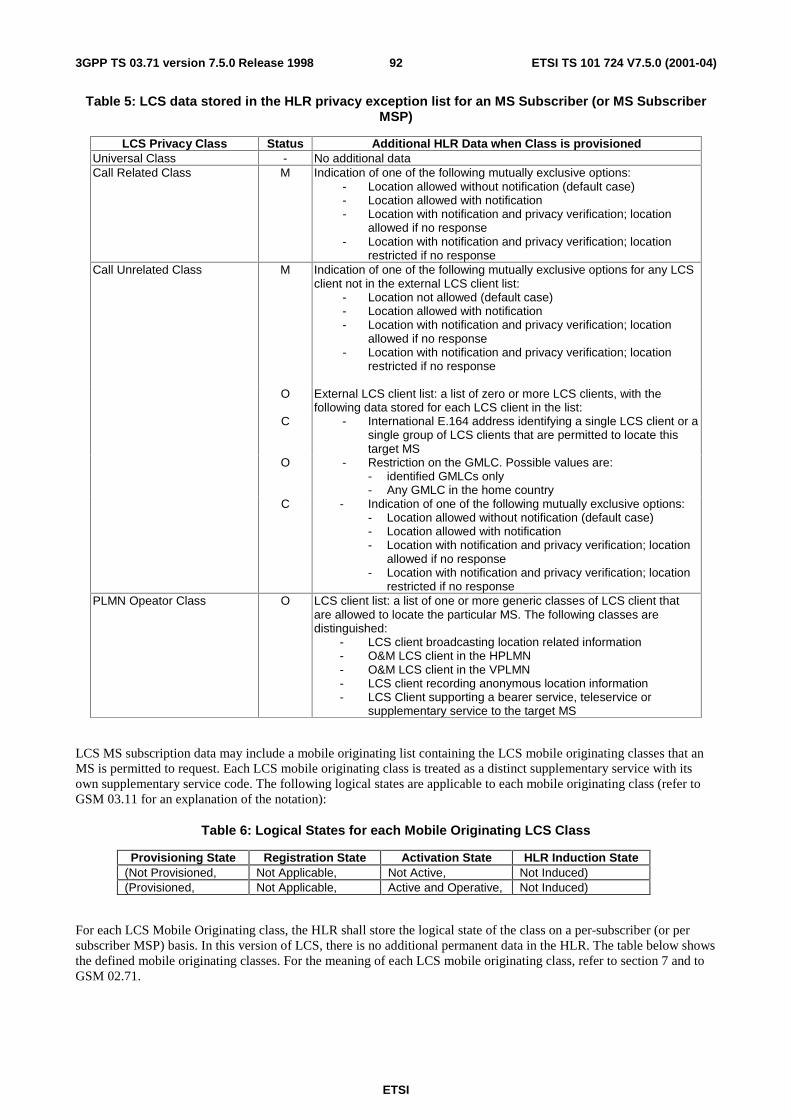
ETSI
ETSI TS 101 724 V7.5.0 (2001-04)923GPP TS 03.71 version 7.5.0 Release 1998
Table 5: LCS data stored in the HLR privacy exception list for an MS Subscriber (or MS Subscriber MSP)
LCS Privacy Class Status Additional HLR Data when Class is provisioned Universal Class - No additional data Call Related Class M Indication of one of the following mutually exclusive options:
- Location allowed without notification (default case) - Location allowed with notification - Location with notification and privacy verification; location
allowed if no response - Location with notification and privacy verification; location
restricted if no response Call Unrelated Class M Indication of one of the following mutually exclusive options for any LCS
client not in the external LCS client list: - Location not allowed (default case) - Location allowed with notification - Location with notification and privacy verification; location
allowed if no response - Location with notification and privacy verification; location
restricted if no response
O External LCS client list: a list of zero or more LCS clients, with the following data stored for each LCS client in the list:
C - International E.164 address identifying a single LCS client or a single group of LCS clients that are permitted to locate this target MS
O - Restriction on the GMLC. Possible values are: - identified GMLCs only - Any GMLC in the home country
C - Indication of one of the following mutually exclusive options: - Location allowed without notification (default case) - Location allowed with notification - Location with notification and privacy verification; location
allowed if no response - Location with notification and privacy verification; location
restricted if no response PLMN Opeator Class O LCS client list: a list of one or more generic classes of LCS client that
are allowed to locate the particular MS. The following classes are distinguished:
- LCS client broadcasting location related information - O&M LCS client in the HPLMN - O&M LCS client in the VPLMN - LCS client recording anonymous location information - LCS Client supporting a bearer service, teleservice or
supplementary service to the target MS
LCS MS subscription data may include a mobile originating list containing the LCS mobile originating classes that an MS is permitted to request. Each LCS mobile originating class is treated as a distinct supplementary service with its own supplementary service code. The following logical states are applicable to each mobile originating class (refer to GSM 03.11 for an explanation of the notation):
Table 6: Logical States for each Mobile Originating LCS Class
Provisioning State Registration State Activation State HLR Induction State (Not Provisioned, Not Applicable, Not Active, Not Induced) (Provisioned, Not Applicable, Active and Operative, Not Induced)
For each LCS Mobile Originating class, the HLR shall store the logical state of the class on a per-subscriber (or per subscriber MSP) basis. In this version of LCS, there is no additional permanent data in the HLR. The table below shows the defined mobile originating classes. For the meaning of each LCS mobile originating class, refer to section 7 and to GSM 02.71.
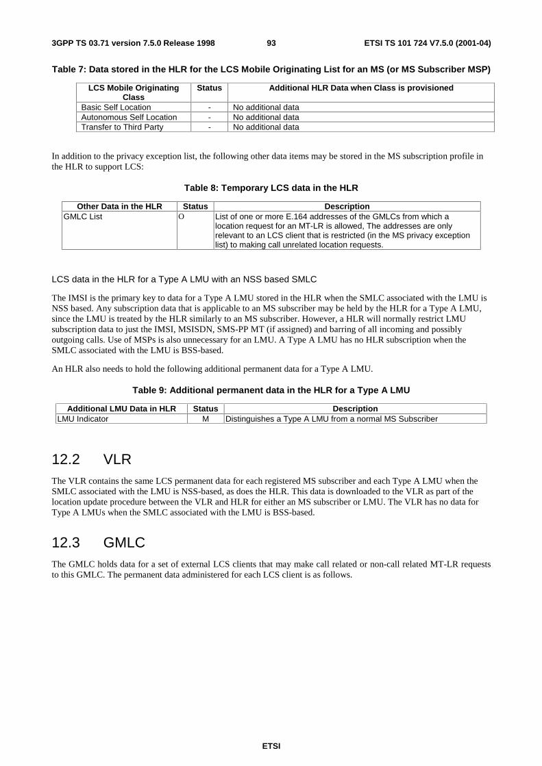
ETSI
ETSI TS 101 724 V7.5.0 (2001-04)933GPP TS 03.71 version 7.5.0 Release 1998
Table 7: Data stored in the HLR for the LCS Mobile Originating List for an MS (or MS Subscriber MSP)
LCS Mobile Originating Class
Status Additional HLR Data when Class is provisioned
Basic Self Location - No additional data Autonomous Self Location - No additional data Transfer to Third Party - No additional data
In addition to the privacy exception list, the following other data items may be stored in the MS subscription profile in the HLR to support LCS:
Table 8: Temporary LCS data in the HLR
Other Data in the HLR Status Description GMLC List O List of one or more E.164 addresses of the GMLCs from which a
location request for an MT-LR is allowed, The addresses are only relevant to an LCS client that is restricted (in the MS privacy exception list) to making call unrelated location requests.
LCS data in the HLR for a Type A LMU with an NSS based SMLC
The IMSI is the primary key to data for a Type A LMU stored in the HLR when the SMLC associated with the LMU is NSS based. Any subscription data that is applicable to an MS subscriber may be held by the HLR for a Type A LMU, since the LMU is treated by the HLR similarly to an MS subscriber. However, a HLR will normally restrict LMU subscription data to just the IMSI, MSISDN, SMS-PP MT (if assigned) and barring of all incoming and possibly outgoing calls. Use of MSPs is also unnecessary for an LMU. A Type A LMU has no HLR subscription when the SMLC associated with the LMU is BSS-based.
An HLR also needs to hold the following additional permanent data for a Type A LMU.
Table 9: Additional permanent data in the HLR for a Type A LMU
Additional LMU Data in HLR Status Description LMU Indicator M Distinguishes a Type A LMU from a normal MS Subscriber
12.2 VLR The VLR contains the same LCS permanent data for each registered MS subscriber and each Type A LMU when the SMLC associated with the LMU is NSS-based, as does the HLR. This data is downloaded to the VLR as part of the location update procedure between the VLR and HLR for either an MS subscriber or LMU. The VLR has no data for Type A LMUs when the SMLC associated with the LMU is BSS-based.
12.3 GMLC The GMLC holds data for a set of external LCS clients that may make call related or non-call related MT-LR requests to this GMLC. The permanent data administered for each LCS client is as follows.
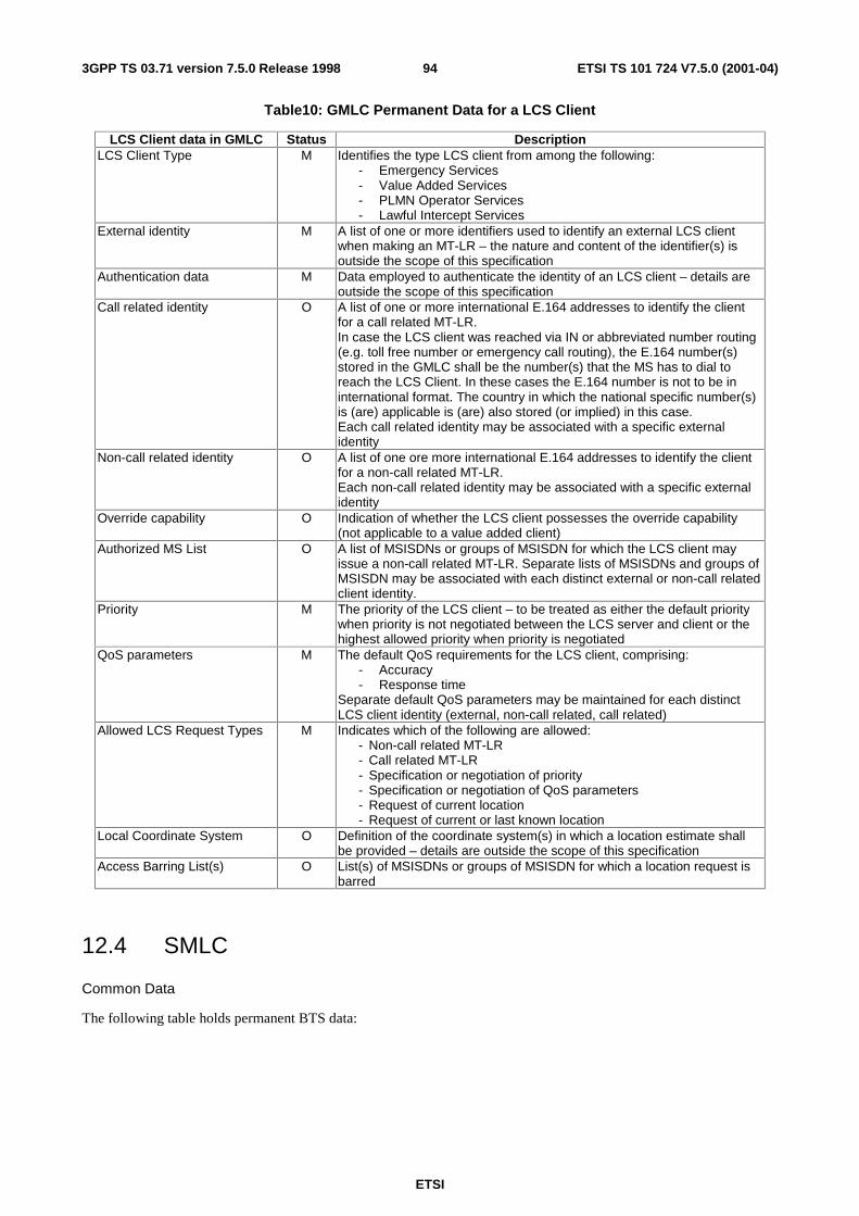
ETSI
ETSI TS 101 724 V7.5.0 (2001-04)943GPP TS 03.71 version 7.5.0 Release 1998
Table10: GMLC Permanent Data for a LCS Client
LCS Client data in GMLC Status Description LCS Client Type M Identifies the type LCS client from among the following:
- Emergency Services - Value Added Services - PLMN Operator Services - Lawful Intercept Services
External identity M A list of one or more identifiers used to identify an external LCS client when making an MT-LR – the nature and content of the identifier(s) is outside the scope of this specification
Authentication data M Data employed to authenticate the identity of an LCS client – details are outside the scope of this specification
Call related identity O A list of one or more international E.164 addresses to identify the client for a call related MT-LR. In case the LCS client was reached via IN or abbreviated number routing (e.g. toll free number or emergency call routing), the E.164 number(s) stored in the GMLC shall be the number(s) that the MS has to dial to reach the LCS Client. In these cases the E.164 number is not to be in international format. The country in which the national specific number(s) is (are) applicable is (are) also stored (or implied) in this case. Each call related identity may be associated with a specific external identity
Non-call related identity O A list of one ore more international E.164 addresses to identify the client for a non-call related MT-LR. Each non-call related identity may be associated with a specific external identity
Override capability O Indication of whether the LCS client possesses the override capability (not applicable to a value added client)
Authorized MS List O A list of MSISDNs or groups of MSISDN for which the LCS client may issue a non-call related MT-LR. Separate lists of MSISDNs and groups of MSISDN may be associated with each distinct external or non-call related client identity.
Priority M The priority of the LCS client – to be treated as either the default priority when priority is not negotiated between the LCS server and client or the highest allowed priority when priority is negotiated
QoS parameters M The default QoS requirements for the LCS client, comprising: - Accuracy - Response time
Separate default QoS parameters may be maintained for each distinct LCS client identity (external, non-call related, call related)
Allowed LCS Request Types M Indicates which of the following are allowed: - Non-call related MT-LR - Call related MT-LR - Specification or negotiation of priority - Specification or negotiation of QoS parameters - Request of current location - Request of current or last known location
Local Coordinate System O Definition of the coordinate system(s) in which a location estimate shall be provided – details are outside the scope of this specification
Access Barring List(s) O List(s) of MSISDNs or groups of MSISDN for which a location request is barred
12.4 SMLC
Common Data
The following table holds permanent BTS data:
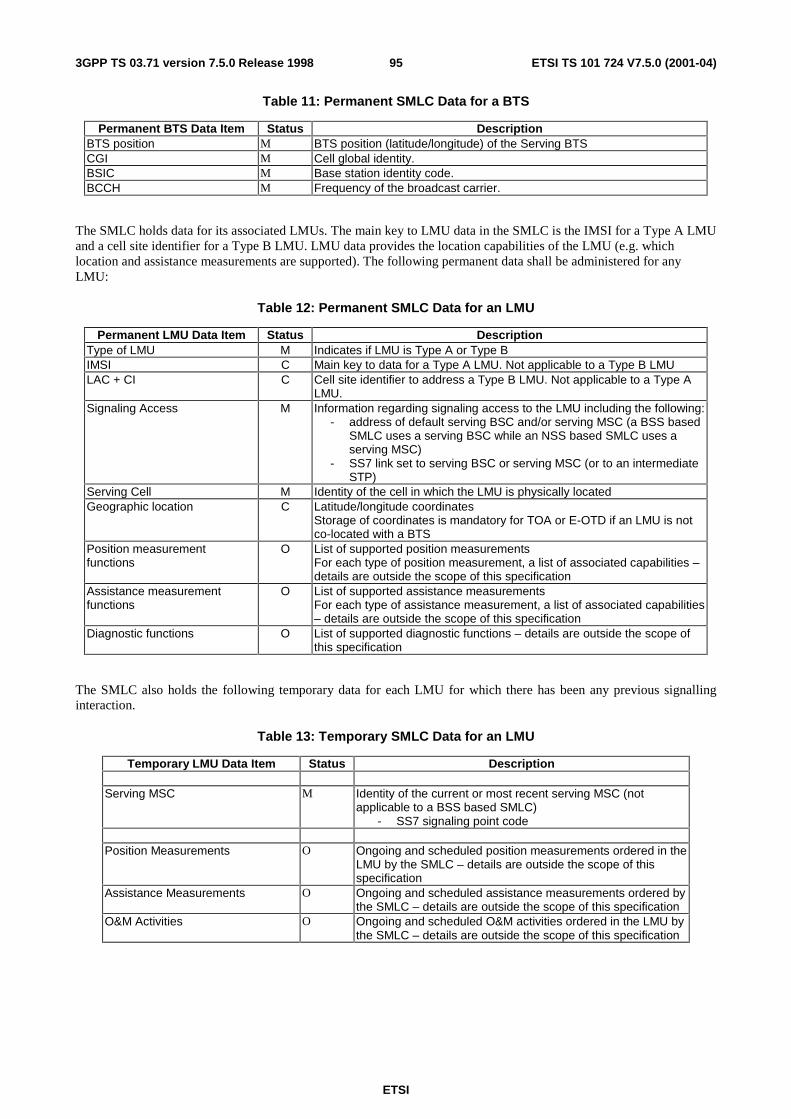
ETSI
ETSI TS 101 724 V7.5.0 (2001-04)953GPP TS 03.71 version 7.5.0 Release 1998
Table 11: Permanent SMLC Data for a BTS
Permanent BTS Data Item Status Description BTS position M BTS position (latitude/longitude) of the Serving BTS CGI M Cell global identity. BSIC M Base station identity code. BCCH M Frequency of the broadcast carrier.
The SMLC holds data for its associated LMUs. The main key to LMU data in the SMLC is the IMSI for a Type A LMU and a cell site identifier for a Type B LMU. LMU data provides the location capabilities of the LMU (e.g. which location and assistance measurements are supported). The following permanent data shall be administered for any LMU:
Table 12: Permanent SMLC Data for an LMU
Permanent LMU Data Item Status Description Type of LMU M Indicates if LMU is Type A or Type B IMSI C Main key to data for a Type A LMU. Not applicable to a Type B LMU LAC + CI C Cell site identifier to address a Type B LMU. Not applicable to a Type A
LMU. Signaling Access M Information regarding signaling access to the LMU including the following:
- address of default serving BSC and/or serving MSC (a BSS based SMLC uses a serving BSC while an NSS based SMLC uses a serving MSC)
- SS7 link set to serving BSC or serving MSC (or to an intermediate STP)
Serving Cell M Identity of the cell in which the LMU is physically located Geographic location C Latitude/longitude coordinates
Storage of coordinates is mandatory for TOA or E-OTD if an LMU is not co-located with a BTS
Position measurement functions
O List of supported position measurements For each type of position measurement, a list of associated capabilities – details are outside the scope of this specification
Assistance measurement functions
O List of supported assistance measurements For each type of assistance measurement, a list of associated capabilities – details are outside the scope of this specification
Diagnostic functions O List of supported diagnostic functions – details are outside the scope of this specification
The SMLC also holds the following temporary data for each LMU for which there has been any previous signalling interaction.
Table 13: Temporary SMLC Data for an LMU
Temporary LMU Data Item Status Description Serving MSC M Identity of the current or most recent serving MSC (not
applicable to a BSS based SMLC) - SS7 signaling point code
Position Measurements O Ongoing and scheduled position measurements ordered in the
LMU by the SMLC – details are outside the scope of this specification
Assistance Measurements O Ongoing and scheduled assistance measurements ordered by the SMLC – details are outside the scope of this specification
O&M Activities O Ongoing and scheduled O&M activities ordered in the LMU by the SMLC – details are outside the scope of this specification
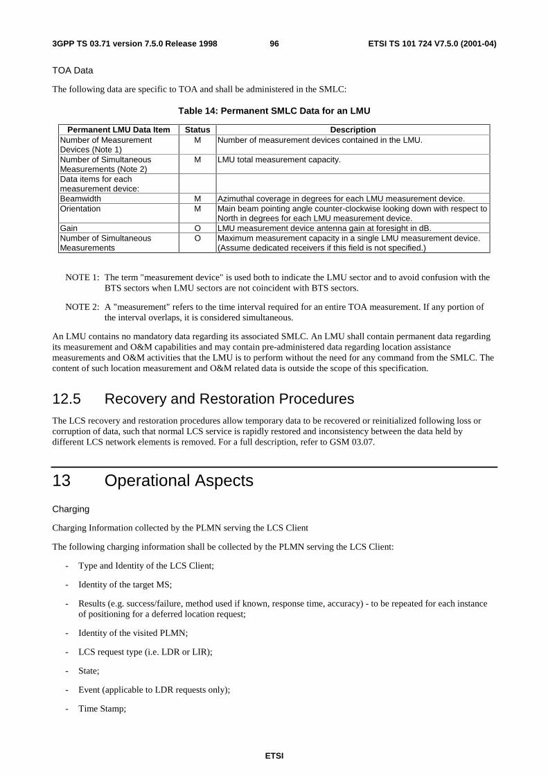
ETSI
ETSI TS 101 724 V7.5.0 (2001-04)963GPP TS 03.71 version 7.5.0 Release 1998
TOA Data
The following data are specific to TOA and shall be administered in the SMLC:
Table 14: Permanent SMLC Data for an LMU
Permanent LMU Data Item Status Description Number of Measurement Devices (Note 1)
M Number of measurement devices contained in the LMU.
Number of Simultaneous Measurements (Note 2)
M LMU total measurement capacity.
Data items for each measurement device:
Beamwidth M Azimuthal coverage in degrees for each LMU measurement device. Orientation M Main beam pointing angle counter-clockwise looking down with respect to
North in degrees for each LMU measurement device. Gain O LMU measurement device antenna gain at foresight in dB. Number of Simultaneous Measurements
O Maximum measurement capacity in a single LMU measurement device. (Assume dedicated receivers if this field is not specified.)
NOTE 1: The term "measurement device" is used both to indicate the LMU sector and to avoid confusion with the BTS sectors when LMU sectors are not coincident with BTS sectors.
NOTE 2: A "measurement" refers to the time interval required for an entire TOA measurement. If any portion of the interval overlaps, it is considered simultaneous.
An LMU contains no mandatory data regarding its associated SMLC. An LMU shall contain permanent data regarding its measurement and O&M capabilities and may contain pre-administered data regarding location assistance measurements and O&M activities that the LMU is to perform without the need for any command from the SMLC. The content of such location measurement and O&M related data is outside the scope of this specification.
12.5 Recovery and Restoration Procedures The LCS recovery and restoration procedures allow temporary data to be recovered or reinitialized following loss or corruption of data, such that normal LCS service is rapidly restored and inconsistency between the data held by different LCS network elements is removed. For a full description, refer to GSM 03.07.
13 Operational Aspects
Charging
Charging Information collected by the PLMN serving the LCS Client
The following charging information shall be collected by the PLMN serving the LCS Client:
- Type and Identity of the LCS Client;
- Identity of the target MS;
- Results (e.g. success/failure, method used if known, response time, accuracy) - to be repeated for each instance of positioning for a deferred location request;
- Identity of the visited PLMN;
- LCS request type (i.e. LDR or LIR);
- State;
- Event (applicable to LDR requests only);
- Time Stamp;
ETSI
ETSI TS 101 724 V7.5.0 (2001-04)973GPP TS 03.71 version 7.5.0 Release 1998
- Type of coordinate system used.
Charging Information Collected by the Visited PLMN
The following charging information shall be collected by the visited PLMN:
- Date and time;
- Type and Identity of the LCS Client (if known)
- Identity of the target MS;
- Location of the target MS (e.g., MSC, location area ID, cell ID, location coordinates);
- Which location services were requested;
- Results (e.g. success/failure, positioning method used, response time, accuracy) - to be repeated for each instance of positioning for a batch location request;
- Identity of the GMLC or PLMN serving the LCS Client;
- State;
- Event (applicable to LDR requests only).
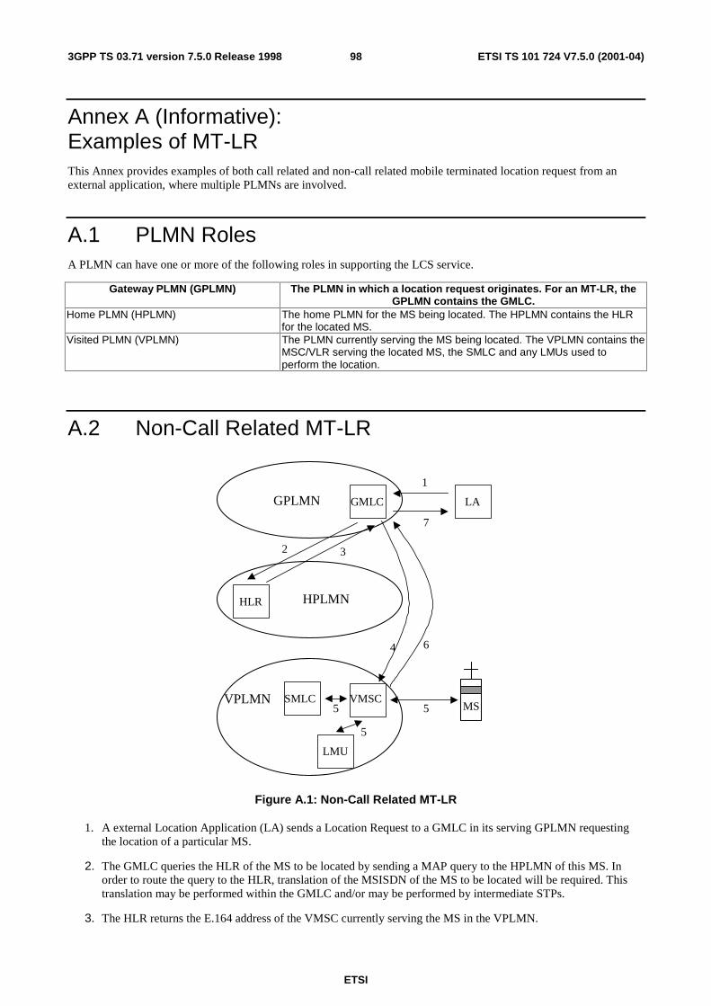
ETSI
ETSI TS 101 724 V7.5.0 (2001-04)983GPP TS 03.71 version 7.5.0 Release 1998
Annex A (Informative): Examples of MT-LR This Annex provides examples of both call related and non-call related mobile terminated location request from an external application, where multiple PLMNs are involved.
A.1 PLMN Roles A PLMN can have one or more of the following roles in supporting the LCS service.
Gateway PLMN (GPLMN) The PLMN in which a location request originates. For an MT-LR, the GPLMN contains the GMLC.
Home PLMN (HPLMN) The home PLMN for the MS being located. The HPLMN contains the HLR for the located MS.
Visited PLMN (VPLMN) The PLMN currently serving the MS being located. The VPLMN contains the MSC/VLR serving the located MS, the SMLC and any LMUs used to perform the location.
A.2 Non-Call Related MT-LR
GPLMN GMLC LA
HPLMNHLR
VPLMN VMSCMS
SMLC
1
7
2 3
64
55
LMU
5
Figure A.1: Non-Call Related MT-LR
1. A external Location Application (LA) sends a Location Request to a GMLC in its serving GPLMN requesting the location of a particular MS.
2. The GMLC queries the HLR of the MS to be located by sending a MAP query to the HPLMN of this MS. In order to route the query to the HLR, translation of the MSISDN of the MS to be located will be required. This translation may be performed within the GMLC and/or may be performed by intermediate STPs.
3. The HLR returns the E.164 address of the VMSC currently serving the MS in the VPLMN.
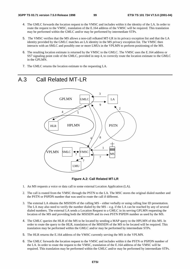
ETSI
ETSI TS 101 724 V7.5.0 (2001-04)993GPP TS 03.71 version 7.5.0 Release 1998
4. The GMLC forwards the location request to the VMSC and includes within it the identity of the LA. In order to route the request to the VMSC, translation of the E.164 address of the VMSC will be required. This translation may be performed within the GMLC and/or may be performed by intermediate STPs.
5. The VMSC verifies that the MS allows a non-call relkated MT-LR in its privacy exception list and that the LA identity provided by the GMLC matches an LA identity in the MS privacy exception list. The VMSC then interacts with an SMLC and possibly one or more LMUs in the VPLMN to perform positioning of the MS.
6. The resulting location estimate is returned by the VMSC to the GMLC. The VMSC uses the E.164 address or SS7 signaling point code of the GMLC, provided in step 4, to correctly route the location estimate to the GMLC in the GPLMN.
7. The GMLC returns the location estimate to the requesting LA.
A.3 Call Related MT-LR
GPLMN GMLC LA
HPLMNHLR
VPLMN VMSCMS
SMLC
3
9
4 5
86
77
LMU
7
1
2
PSTN
Figure A.2: Call Related MT-LR
1. An MS requests a voice or data call to some external Location Application (LA).
2. The call is routed from the VMSC through the PSTN to the LA. The MSC stores the original dialed number and the PSTN or PSPDN number that was used to route the call if different.
3. The external LA obtains the MSISDN of the calling MS – either verbally or using calling line ID presentation. The LA may also need to verify the number dialed by the MS – e.g. if the LA can be reached by any of several dialed numbers. The external LA sends a Location Request to a GMLC in its serving GPLMN requesting the location of the MS and providing both the MSISDN and its own PSTN PSPDN number as used by the MS.
4. The GMLC queries the HLR of the MS to be located by sending a MAP query to the HPLMN of this MS. In order to route the query to the HLR, translation of the MSISDN of the MS to be located will be required. This translation may be performed within the GMLC and/or may be performed by intermediate STPs.
5. The HLR returns the E.164 address of the VMSC currently serving the MS in the VPLMN.
6. The GMLC forwards the location request to the VMSC and includes within it the PSTN or PSPDN number of the LA. In order to route the request to the VMSC, translation of the E.164 address of the VMSC will be required. This translation may be performed within the GMLC and/or may be performed by intermediate STPs.

ETSI
ETSI TS 101 724 V7.5.0 (2001-04)1003GPP TS 03.71 version 7.5.0 Release 1998
7. The VMSC verifies that the MS allows a call related MT-LR in its privacy exception list, that it currently has an originated call established and that the PSTN or PSPDN number supplied by the GMLC matches the number either dialed by the MS or used to route the call. The VMSC then interacts with an SMLC and possibly one or more LMUs in the VPLMN to perform positioning of the MS.
8. The resulting location estimate is returned by the VMSC to the GMLC. The VMSC uses the E.164 address or SS7 signaling point code of the GMLC, provided in step 4, to correctly route the location estimate to the GMLC in the GPLMN.
9. The GMLC returns the location estimate to the requesting LA.

ETSI
ETSI TS 101 724 V7.5.0 (2001-04)1013GPP TS 03.71 version 7.5.0 Release 1998
Annex B (Informative): Description of TOA The uplink TOA positioning method is based on measuring the Time of Αrival (TOA) of a known signal sent from the mobile and received at three or more measurement units. The known signal is the access bursts generated by having the mobile perform an asynchronous handover. This method will work with existing mobiles; i.e. there is no modification to the handset required.
The Serving Mobile Location Center (SMLC) calculates Time Difference of Αrrival (TDOA) values by pair-wise subtracting the TOA values. The mobile position is then calculated via hyperbolic trilateration assuming that:
a) the geographical coordinates of the measurement units are known, and
b) the timing offset between the measurement units involved in the measurement are known, e.g. by the use of absolute GPS time at the measurement units, or by using reference measurement units (sometimes referred to as "reference mobiles") situated at known locations to determine RTD (Real Time Difference) values.
Access bursts are used for detecting the TOA at the listening measurement units. At a positioning request, the units which should measure the TOA of the MS signal are selected and configured to listen at the correct frequency. The MS is then forced to perform an asynchronous handover.. Under such circumstances, the MS is transmitting up to 70 access bursts (320 ms) with specified power on a traffic channel (which may be frequency hopping).
The TOA measurements are performed at each measurement unit by integrating the received bursts to enhance the sensitivity, and therefore increasing the detection probability and measurement accuracy, and by applying a multipath rejection technique to accurately measure the arrival time of the Line of Sight component of the signal. The presence of diversity, e.g. antenna diversity and frequency hopping will improve the multipath rejection capability and therefore the measurement accuracy.
When an application requires the position of a mobile, it has to send a request to SMLC the identifacation of the mobile and the accuracy level parameter. Depending on this accuracy level, SMLC decides how many measurement units to be included in the positioning request. The measured TOA values together with the accuracy parameter of the TOA value are collected and transmitted to the SMLC. The SMLC utilizes the TOA measurements in combination with information about the coordinates of the measurement units and the RTD values (a and b above) to produce a position estimate. The SMLC delivers the position estimate together with an uncertainty estimate to the application.
The uplink TOA method requires additional hardware (LMUs) to accurately measure the arrival time of the bursts. Different implementation options exist for this positioning method. For instance, it is possible to either integrate the measuring units in the BTSs or implement them as stand-alone units. In case the measurement units are implemented as stand alone units, the communication between the measurement units and the network is preferably carried out over the air interface. The stand-alone units may have separate antennas or share antennas with an existing BTS.
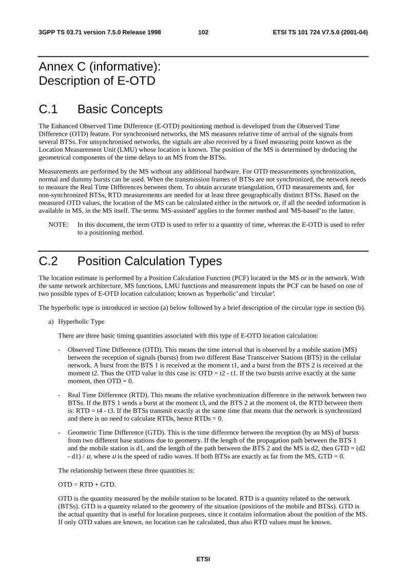
ETSI
ETSI TS 101 724 V7.5.0 (2001-04)1023GPP TS 03.71 version 7.5.0 Release 1998
Annex C (informative): Description of E-OTD
C.1 Basic Concepts The Enhanced Observed Time Difference (E-OTD) positioning method is developed from the Observed Time Difference (OTD) feature. For synchronised networks, the MS measures relative time of arrival of the signals from several BTSs. For unsynchronised networks, the signals are also received by a fixed measuring point known as the Location Measurement Unit (LMU) whose location is known. The position of the MS is determined by deducing the geometrical components of the time delays to an MS from the BTSs.
Measurements are performed by the MS without any additional hardware. For OTD measurements synchronization, normal and dummy bursts can be used. When the transmission frames of BTSs are not synchronized, the network needs to measure the Real Time Differences between them. To obtain accurate triangulation, OTD measurements and, for non-synchronized BTSs, RTD measurements are needed for at least three geographically distinct BTSs. Based on the measured OTD values, the location of the MS can be calculated either in the network or, if all the needed information is available in MS, in the MS itself. The terms ’MS-assisted’ applies to the former method and ’MS-based’ to the latter.
NOTE: In this document, the term OTD is used to refer to a quantity of time, whereas the E-OTD is used to refer to a positioning method.
C.2 Position Calculation Types The location estimate is performed by a Position Calculation Function (PCF) located in the MS or in the network. With the same network architecture, MS functions, LMU functions and measurement inputs the PCF can be based on one of two possible types of E-OTD location calculation; known as ’hyperbolic’ and ’circular’.
The hyperbolic type is introduced in section (a) below followed by a brief description of the circular type in section (b).
a) Hyperbolic Type
There are three basic timing quantities associated with this type of E-OTD location calculation:
- Observed Time Difference (OTD). This means the time interval that is observed by a mobile station (MS) between the reception of signals (bursts) from two different Base Transceiver Stations (BTS) in the cellular network. A burst from the BTS 1 is received at the moment t1, and a burst from the BTS 2 is received at the moment t2. Thus the OTD value in this case is: OTD = t2 - t1. If the two bursts arrive exactly at the same moment, then OTD = 0.
- Real Time Difference (RTD). This means the relative synchronization difference in the network between two BTSs. If the BTS 1 sends a burst at the moment t3, and the BTS 2 at the moment t4, the RTD between them is: RTD = t4 - t3. If the BTSs transmit exactly at the same time that means that the network is synchronized and there is no need to calculate RTDs, hence RTDs = 0.
- Geometric Time Difference (GTD). This is the time difference between the reception (by an MS) of bursts from two different base stations due to geometry. If the length of the propagation path between the BTS 1 and the mobile station is d1, and the length of the path between the BTS 2 and the MS is d2, then GTD = (d2 - d1) / υ, where υ is the speed of radio waves. If both BTSs are exactly as far from the MS, GTD = 0.
The relationship between these three quantities is:
OTD = RTD + GTD.
OTD is the quantity measured by the mobile station to be located. RTD is a quantity related to the network (BTSs). GTD is a quantity related to the geometry of the situation (positions of the mobile and BTSs). GTD is the actual quantity that is useful for location purposes, since it contains information about the position of the MS. If only OTD values are known, no location can be calculated, thus also RTD values must be known.
ETSI
ETSI TS 101 724 V7.5.0 (2001-04)1033GPP TS 03.71 version 7.5.0 Release 1998
The MS location estimate can be computed in the MS or by the network depending on implementation. Whichever method is used the MS location estimate is calculated from the GTD (as calculated from the measured OTD and known or measured RTD) based on the fact that the possible location for the MS observing a constant GTD value (d2 - d1 = constant) between two BTSs is a hyperbola. The MS can be located in the intersection of two hyperbolas obtained with three base stations and two GTDs. If more GTDs are available the possible location area can be reduced.
d
d
1
2
Base
Base
Base
Measurementerror margin
Figure C.1: E-OTD location (hyperbolic)
The dashed line represents the determined GTD, i.e., represents a constant difference in distance to two BTSs. The measurement result is not exact, thus the gray area represents the area of uncertainty for the MS based on that OTD measurement. The black area at the intersection of the hyperbolas is the calculated most likely location for the MS.
b) Circular Type
The E-OTD Circular location calculation type does not measure time differences at the MS and LMU between the receipt of signals from pairs of BTSs. Rather, it measures the arrival time of those signals individually.
There are five quantities associated with the circular type of E-OTD:
- The Observed Time at the MS (MOT) at which a signal arrives from a BTS. This is a time measured against the MS’s internal clock.
- The Observed Time at the LMU (LOT) at which a signal arrives from a BTS. This is a time measured against the LMU’s internal clock. In general there will be a time offset ε between the MS’s internal clock and the LMU’s internal clock.
- The geometrical Distance from MS to BTS (DMB).
- The geometrical Distance from LMU to BTS (DLB).
These quantities are related by:
DMB - DLB = υ (MOT - LOT + ε)
in which υ is the speed of the signals (speed of radio waves) and there will be one such equation for each BTS. Since there are three unknown quantities (MS position x, y and clock offset ε) at least three BTSs are required to solve for the MS location and the unknown clock offset ε. This is the same total number of BTSs as is required for the hyperbolic type of E-OTD. The position of the MS is defined by the intersection of circles centred on the BTSs common to observations made by the MS and LMUs, hence the notation ’circular’ as the E-OTD type as shown in Figure C.2 below.
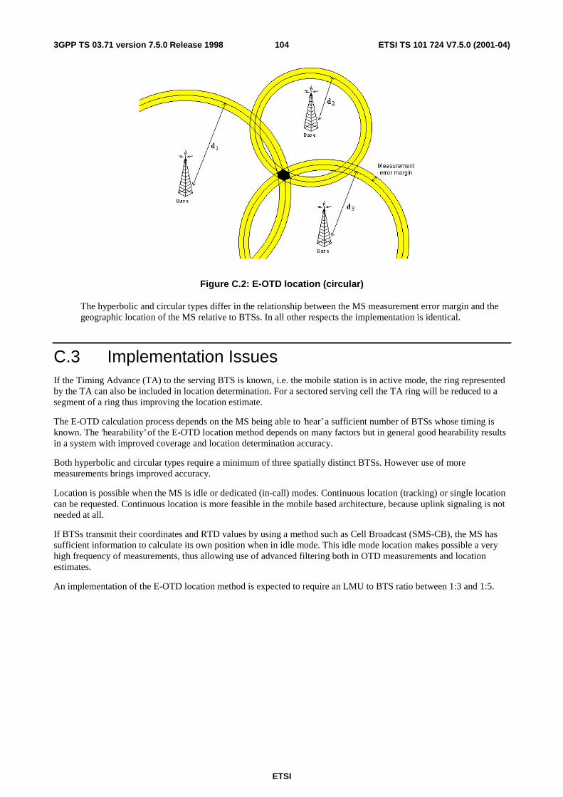
ETSI
ETSI TS 101 724 V7.5.0 (2001-04)1043GPP TS 03.71 version 7.5.0 Release 1998
Figure C.2: E-OTD location (circular)
The hyperbolic and circular types differ in the relationship between the MS measurement error margin and the geographic location of the MS relative to BTSs. In all other respects the implementation is identical.
C.3 Implementation Issues If the Timing Advance (TA) to the serving BTS is known, i.e. the mobile station is in active mode, the ring represented by the TA can also be included in location determination. For a sectored serving cell the TA ring will be reduced to a segment of a ring thus improving the location estimate.
The E-OTD calculation process depends on the MS being able to ’hear’ a sufficient number of BTSs whose timing is known. The ’hearability’ of the E-OTD location method depends on many factors but in general good hearability results in a system with improved coverage and location determination accuracy.
Both hyperbolic and circular types require a minimum of three spatially distinct BTSs. However use of more measurements brings improved accuracy.
Location is possible when the MS is idle or dedicated (in-call) modes. Continuous location (tracking) or single location can be requested. Continuous location is more feasible in the mobile based architecture, because uplink signaling is not needed at all.
If BTSs transmit their coordinates and RTD values by using a method such as Cell Broadcast (SMS-CB), the MS has sufficient information to calculate its own position when in idle mode. This idle mode location makes possible a very high frequency of measurements, thus allowing use of advanced filtering both in OTD measurements and location estimates.
An implementation of the E-OTD location method is expected to require an LMU to BTS ratio between 1:3 and 1:5.
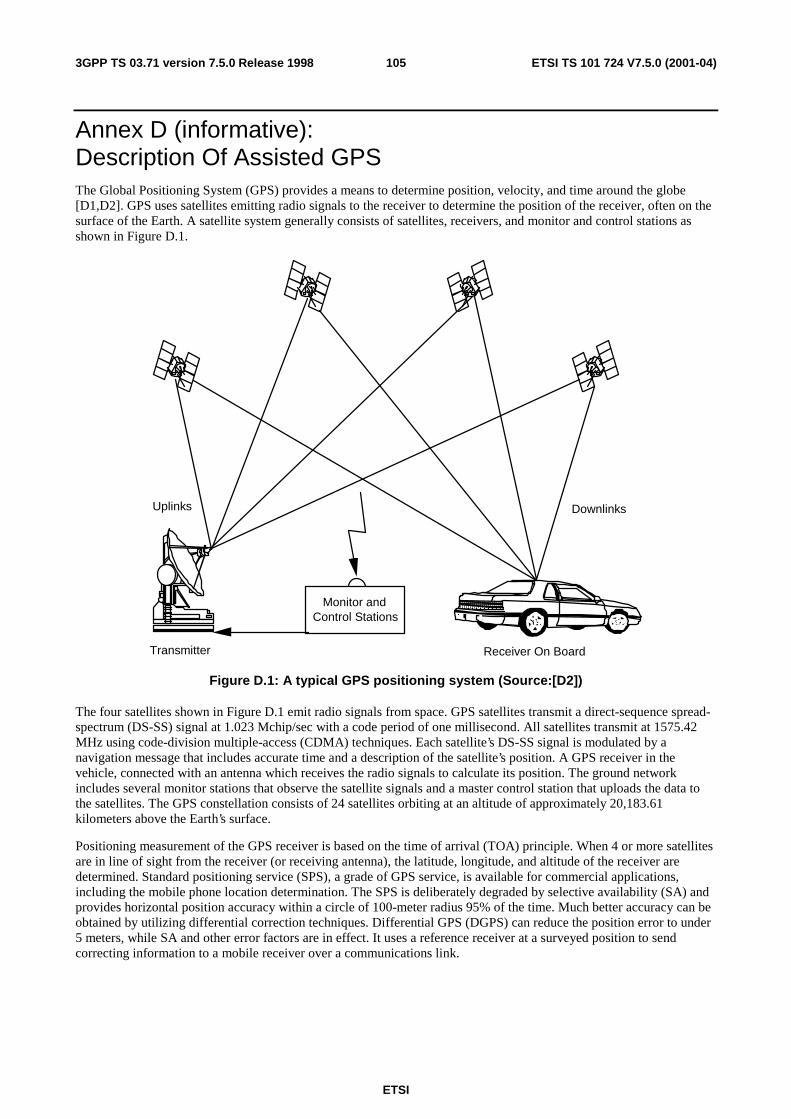
ETSI
ETSI TS 101 724 V7.5.0 (2001-04)1053GPP TS 03.71 version 7.5.0 Release 1998
Annex D (informative): Description Of Assisted GPS The Global Positioning System (GPS) provides a means to determine position, velocity, and time around the globe [D1,D2]. GPS uses satellites emitting radio signals to the receiver to determine the position of the receiver, often on the surface of the Earth. A satellite system generally consists of satellites, receivers, and monitor and control stations as shown in Figure D.1.
Transmitter Receiver On Board
DownlinksUplinks
Monitor andControl Stations
Figure D.1: A typical GPS positioning system (Source:[D2])
The four satellites shown in Figure D.1 emit radio signals from space. GPS satellites transmit a direct-sequence spread-spectrum (DS-SS) signal at 1.023 Mchip/sec with a code period of one millisecond. All satellites transmit at 1575.42 MHz using code-division multiple-access (CDMA) techniques. Each satellite’s DS-SS signal is modulated by a navigation message that includes accurate time and a description of the satellite’s position. A GPS receiver in the vehicle, connected with an antenna which receives the radio signals to calculate its position. The ground network includes several monitor stations that observe the satellite signals and a master control station that uploads the data to the satellites. The GPS constellation consists of 24 satellites orbiting at an altitude of approximately 20,183.61 kilometers above the Earth’s surface.
Positioning measurement of the GPS receiver is based on the time of arrival (TOA) principle. When 4 or more satellites are in line of sight from the receiver (or receiving antenna), the latitude, longitude, and altitude of the receiver are determined. Standard positioning service (SPS), a grade of GPS service, is available for commercial applications, including the mobile phone location determination. The SPS is deliberately degraded by selective availability (SA) and provides horizontal position accuracy within a circle of 100-meter radius 95% of the time. Much better accuracy can be obtained by utilizing differential correction techniques. Differential GPS (DGPS) can reduce the position error to under 5 meters, while SA and other error factors are in effect. It uses a reference receiver at a surveyed position to send correcting information to a mobile receiver over a communications link.
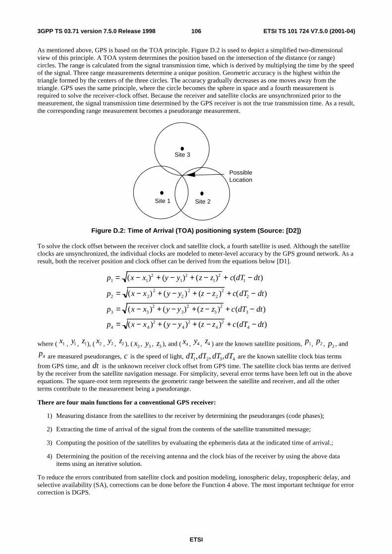
ETSI
ETSI TS 101 724 V7.5.0 (2001-04)1063GPP TS 03.71 version 7.5.0 Release 1998
As mentioned above, GPS is based on the TOA principle. Figure D.2 is used to depict a simplified two-dimensional view of this principle. A TOA system determines the position based on the intersection of the distance (or range) circles. The range is calculated from the signal transmission time, which is derived by multiplying the time by the speed of the signal. Three range measurements determine a unique position. Geometric accuracy is the highest within the triangle formed by the centers of the three circles. The accuracy gradually decreases as one moves away from the triangle. GPS uses the same principle, where the circle becomes the sphere in space and a fourth measurement is required to solve the receiver-clock offset. Because the receiver and satellite clocks are unsynchronized prior to the measurement, the signal transmission time determined by the GPS receiver is not the true transmission time. As a result, the corresponding range measurement becomes a pseudorange measurement.
PossibleLocation
Site 2Site 1
Site 3
Figure D.2: Time of Arrival (TOA) positioning system (Source: [D2])
To solve the clock offset between the receiver clock and satellite clock, a fourth satellite is used. Although the satellite clocks are unsynchronized, the individual clocks are modeled to meter-level accuracy by the GPS ground network. As a result, both the receiver position and clock offset can be derived from the equations below [D1].
p1 = (x − x1)2 + (y − y1)
2 + (z − z1)2 + c(dT1 − dt)
p2 = (x − x2)2 + (y − y2 )2 + (z − z2 )2 + c(dT2 − dt)
p3 = (x − x3 )2 + (y − y3)2 +(z − z3 )2 + c(dT3 − dt)
p4 = (x − x4 )2 + (y − y4 )2 + (z − z4 )2 + c(dT4 − dt)
where ( x1 , y1 , z1), ( x2 , y2 , z2 ), ( x3 , y3 , z3 ), and ( x4 , y4 , z4 ) are the known satellite positions, p1, p2 , p3 , and
p4 are measured pseudoranges, c is the speed of light, dT1,dT2, dT3,dT4 are the known satellite clock bias terms
from GPS time, and dt is the unknown receiver clock offset from GPS time. The satellite clock bias terms are derived by the receiver from the satellite navigation message. For simplicity, several error terms have been left out in the above equations. The square-root term represents the geometric range between the satellite and receiver, and all the other terms contribute to the measurement being a pseudorange.
There are four main functions for a conventional GPS receiver:
1) Measuring distance from the satellites to the receiver by determining the pseudoranges (code phases);
2) Extracting the time of arrival of the signal from the contents of the satellite transmitted message;
3) Computing the position of the satellites by evaluating the ephemeris data at the indicated time of arrival.;
4) Determining the position of the receiving antenna and the clock bias of the receiver by using the above data items using an iterative solution.
To reduce the errors contributed from satellite clock and position modeling, ionospheric delay, tropospheric delay, and selective availability (SA), corrections can be done before the Function 4 above. The most important technique for error correction is DGPS.
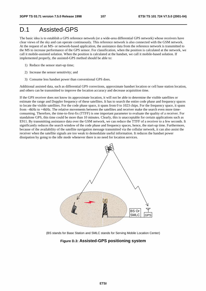
ETSI
ETSI TS 101 724 V7.5.0 (2001-04)1073GPP TS 03.71 version 7.5.0 Release 1998
D.1 Assisted-GPS The basic idea is to establish a GPS reference network (or a wide-area differential GPS network) whose receivers have clear views of the sky and can operate continuously. This reference network is also connected with the GSM network. At the request of an MS- or network-based application, the assistance data from the reference network is transmitted to the MS to increase performance of the GPS sensor. For classification, when the position is calculated at the network, we call it mobile-assisted solution. When the position is calculated at the handset, we call it mobile-based solution. If implemented properly, the assisted-GPS method should be able to:
1) Reduce the sensor start-up time;
2) Increase the sensor sensitivity; and
3) Consume less handset power than conventional GPS does.
Additional assisted data, such as differential GPS corrections, approximate handset location or cell base station location, and others can be transmitted to improve the location accuracy and decrease acquisition time.
If the GPS receiver does not know its approximate location, it will not be able to determine the visible satellites or estimate the range and Doppler frequency of these satellites. It has to search the entire code phase and frequency spaces to locate the visible satellites. For the code phase space, it spans from 0 to 1023 chips. For the frequency space, it spans from –4kHz to +4kHz. The relative movements between the satellites and receiver make the search even more time-consuming. Therefore, the time-to-first-fix (TTFF) is one important parameter to evaluate the quality of a receiver. For standalone GPS, this time could be more than 10 minutes. Clearly, this is unacceptable for certain applications such as E911. By transmitting assistance data over the GSM network, we can reduce the TTFF of a receiver to a few seconds. It significantly reduces the search window of the code phase and frequency spaces, hence, the start-up time. Furthermore, because of the availability of the satellite navigation message transmitted via the cellular network, it can also assist the receiver when the satellite signals are too weak to demodulate useful information. It reduces the handset power dissipation by going to the idle mode whenever there is no need for location services.
BS OrSMLC GPS
(BS stands for Base Station and SMLC stands for Serving Mobile Location Center)
Figure D.3: Assisted-GPS positioning system
ETSI
ETSI TS 101 724 V7.5.0 (2001-04)1083GPP TS 03.71 version 7.5.0 Release 1998
D.2 MS-Assisted GPS The mobile-assisted solution shifts the majority of the traditional GPS receiver functions to the network processor. This method requires an antenna, RF section, and digital processor for making measurments by generating replica codes and correlating them with the received GPS signals. The network transmits a very short assistance message to the mobile station (MS), consisting of time, visible satellite list, satellite signal Doppler, and code phase search window. These parameters help the embedded GPS sensor reduce the GPS acquisition time considerably. These assistance data are valid for a few minutes. It returns from the MS the pseudorange data processed by the GPS sensor. After receiving the pseduorange data, the corresponding network processor or location server estimates the position of the MS. The differential correction can be applied to the final result at the network side to improve the position accuracy.
D.3 MS-Based GPS The MS-based solution maintains a fully-functional GPS receiver in the MS. This requires the same functionality as described in clause B.2, plus additional means for computing the positions of the satelites and ultimately the MS’s position. In the initial start-up scenario, significantly more data must be provided to the MS than for the MS-assisted case. However, this data is valid for four hours or more and can be updated as necessary over time. Typical transmissions include time, reference location, satellite ephemeris and clock corrections. If better position accuracy is required for certain applications, DGPS data must be transmitted to the MS frequently (approximately every 30 seconds). Since the DGPS data is valid for a large geographical area, one centrally located reference receiver can be used to service this large region. The final position of the MS is generated at the MS itself. The calculated MS location can then be sent to an application outside of the MS if required.
D.4 References [D1] Yilin Zhao, Vehicle Location and Navigation Systems, Norwood, MA: Artech House, 1997.
[D2] Yilin Zhao, "Vehicle Navigation and Information Systems," Encyclopedia of Electrical and Electronics Engineering, John G. Webster (Ed.), New York: John Wiley & Sons, Vol. 23, pp. 106-118, 1999.

ETSI
ETSI TS 101 724 V7.5.0 (2001-04)1093GPP TS 03.71 version 7.5.0 Release 1998
Annex E (informative): Change History
Change history Meeting# Spec Version CR <Phase> New Version Subject/Comment
SMG#29 03.71 - R98 7.0.0 Approved at SMG#29 SMG#30 03.71 7.0.0 A001r1 R98 7.1.0 Addition of further LCS functionality in GSM
Release 98 SMG#30bis 03.71 7.1.0 A003 R98 7.2.1 Addition of further LCS functionality in GSM
Release 98 (CR A002r1 was withdrawn) SMG#31 03.71 7.2.1 A005 R98 7.3.0 Corrections for LCS Open Issues SMG#31 03.71 7.2.1 A006 R98 7.3.0 Clarify provision of GPS and E-OTD
assistance data to a target MS SMG#31 03.71 7.2.1 A007 R98 7.3.0 Modifications to support broadcast of GPS
assistance data SP-08 03.71 7.3.0 A008 R98 7.4.0 Ensure reliable privacy verification for value
added LCS MT-LR SP-11 03.71 7.4.0 A011 R98 7.5.0 Correction; BSSMAP Location Information
Report replaced by BSSMAP Connection Oriented Information
SP-11 03.71 7.4.0 A013 R98 7.5.0 LCS error handling (Inter-BSC Handover) SP-11 03.71 7.4.0 A018 R98 7.5.0 Applicability of LCS services in CS domain to
GPRS mobile stations SP-11 03.71 7.4.0 A015 R98 7.5.0 Privacy check procedures for call related
MT-LR, GSM 03.71 SP-11 03.71 7.4.0 A016 R98 7.5.0 Corrections of A-GPS Broadcast
Descriptions SP-11 03.71 7.4.0 A020 R98 7.5.0 Geographical shape restriction in LCS SP-11 03.71 7.4.0 A022 R98 7.5.0 Segmentation/Pre-emption for LCS

110
ETSI
ETSI TS 101 724 V7.5.0 (2001-04)3GPP TS 03.71 version 7.5.0 Release 1998
History
Document history
V7.1.0 August 1999 Publication
V7.2.1 January 2000 Publication
V7.3.0 February 2000 Publication
V7.4.0 October 2000 Publication
V7.5.0 April 2001 Publication