Embed Size (px)
Citation preview
Trunnion Mounted Ball Valves
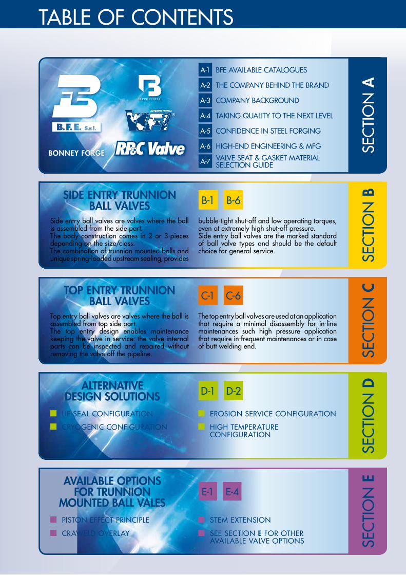
TABLE OF CONTENTS
SEC
TIO
N E
SEC
TIO
N BSIDE ENTRY TRUNNION
BALL VALVES B-1 B-6
Side entry ball valves are valves where the ball is assembled from the side part.The body construction comes in 2 or 3-pieces depending on the size/class.The combination of trunnion mounted balls and unique spring-loaded upstream sealing, provides
bubble-tight shut-off and low operating torques, even at extremely high shut-off pressure.Side entry ball valves are the marked standard of ball valve types and should be the default choice for general service.
SEC
TIO
N CTOP ENTRY TRUNNION
BALL VALVES C-1 C-6
Top entry ball valves are valves where the ball is assembled from top side part.The top entry design enables maintenance keeping the valve in service: the valve internal parts can be inspected and repaired without removing the valve off the pipeline.
The top entry ball valves are used at an application that require a minimal disassembly for in-line maintenances such high pressure application that require in-frequent maintenances or in case of butt welding end.
BONNEY FORGE SEC
TIO
N A
BFE AVAILABLE CATALOGUESA-1
A-4 TAKING QUALITY TO THE NEXT LEVEL
A-5 CONFIDENCE IN STEEL FORGING
A-2 THE COMPANY BEHIND THE BRAND
A-3 COMPANY BACKGROUND
A-6 HIGH-END ENGINEERING & MFG
A-7 VALVE SEAT & GASKET MATERIAL SELECTION GUIDE
SEC
TIO
N DALTERNATIVE
DESIGN SOLUTIONS D-1 D-2
LIP-SEAL CONFIGURATION
CRYOGENIC CONFIGURATION
EROSION SERVICE CONFIGURATION
HIGH TEMPERATURE CONFIGURATION
PISTON EFFECT PRINCIPLE
CRAWELD OVERLAY
STEM EXTENSION
SEE SECTION E FOR OTHER AVAILABLE VALVE OPTIONS
AVAILABLE OPTIONS FOR TRUNNION
MOUNTED BALL VALESE-1 E-4
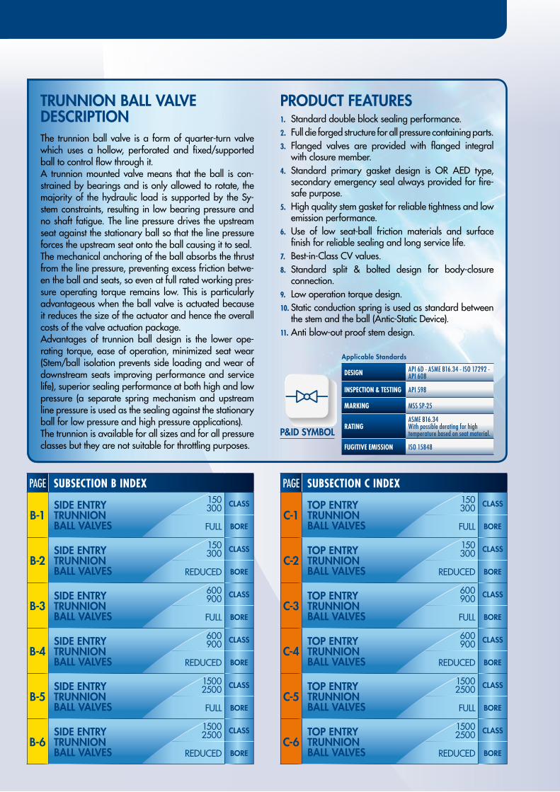
TRUNNION BALL VALVE DESCRIPTION
PRODUCT FEATURES
The trunnion ball valve is a form of quarter-turn valve which uses a hollow, perforated and fixed/supported ball to control flow through it.A trunnion mounted valve means that the ball is con-strained by bearings and is only allowed to rotate, the majority of the hydraulic load is supported by the Sy-stem constraints, resulting in low bearing pressure and no shaft fatigue. The line pressure drives the upstream seat against the stationary ball so that the line pressure forces the upstream seat onto the ball causing it to seal.The mechanical anchoring of the ball absorbs the thrust from the line pressure, preventing excess friction betwe-en the ball and seats, so even at full rated working pres-sure operating torque remains low. This is particularly advantageous when the ball valve is actuated because it reduces the size of the actuator and hence the overall costs of the valve actuation package.Advantages of trunnion ball design is the lower ope-rating torque, ease of operation, minimized seat wear (Stem/ball isolation prevents side loading and wear of downstream seats improving performance and service life), superior sealing performance at both high and low pressure (a separate spring mechanism and upstream line pressure is used as the sealing against the stationary ball for low pressure and high pressure applications).The trunnion is available for all sizes and for all pressure classes but they are not suitable for throttling purposes.
1. Standard double block sealing performance.2. Full die forged structure for all pressure containing parts.3. Flanged valves are provided with flanged integral
with closure member.4. Standard primary gasket design is OR AED type,
secondary emergency seal always provided for fire-safe purpose.
5. High quality stem gasket for reliable tightness and low emission performance.
6. Use of low seat-ball friction materials and surface finish for reliable sealing and long service life.
7. Best-in-Class CV values.8. Standard split & bolted design for body-closure
connection.9. Low operation torque design.10. Static conduction spring is used as standard between
the stem and the ball (Antic-Static Device).11. Anti blow-out proof stem design.
P&ID SYMBOL
PAGE SUBSECTION B INDEX
B-1150300 CLASS
FULL BORE
B-2150300 CLASS
REDUCED BORE
B-3600900 CLASS
FULL BORE
B-4600900 CLASS
REDUCED BORE
B-515002500 CLASS
FULL BORE
B-615002500 CLASS
REDUCED BORE
SIDE ENTRYTRUNNION BALL VALVES
SIDE ENTRYTRUNNION BALL VALVES
SIDE ENTRYTRUNNION BALL VALVES
SIDE ENTRYTRUNNION BALL VALVES
SIDE ENTRYTRUNNION BALL VALVES
SIDE ENTRYTRUNNION BALL VALVES
PAGE SUBSECTION C INDEX
C-1150300 CLASS
FULL BORE
C-2150300 CLASS
REDUCED BORE
C-3600900 CLASS
FULL BORE
C-4600900 CLASS
REDUCED BORE
C-515002500 CLASS
FULL BORE
C-615002500 CLASS
REDUCED BORE
TOP ENTRYTRUNNION BALL VALVES
TOP ENTRYTRUNNION BALL VALVES
TOP ENTRYTRUNNION BALL VALVES
TOP ENTRYTRUNNION BALL VALVES
TOP ENTRYTRUNNION BALL VALVES
TOP ENTRYTRUNNION BALL VALVES
Applicable Standards
DESIGN API 6D - ASME B16.34 - ISO 17292 - API 608
INSPECTION & TESTING API 598
MARKING MSS SP-25
RATINGASME B16.34With possible derating for high temperature based on seat material.
FUGITIVE EMISSION ISO 15848
BFE AVAILABLE CATALOGUES
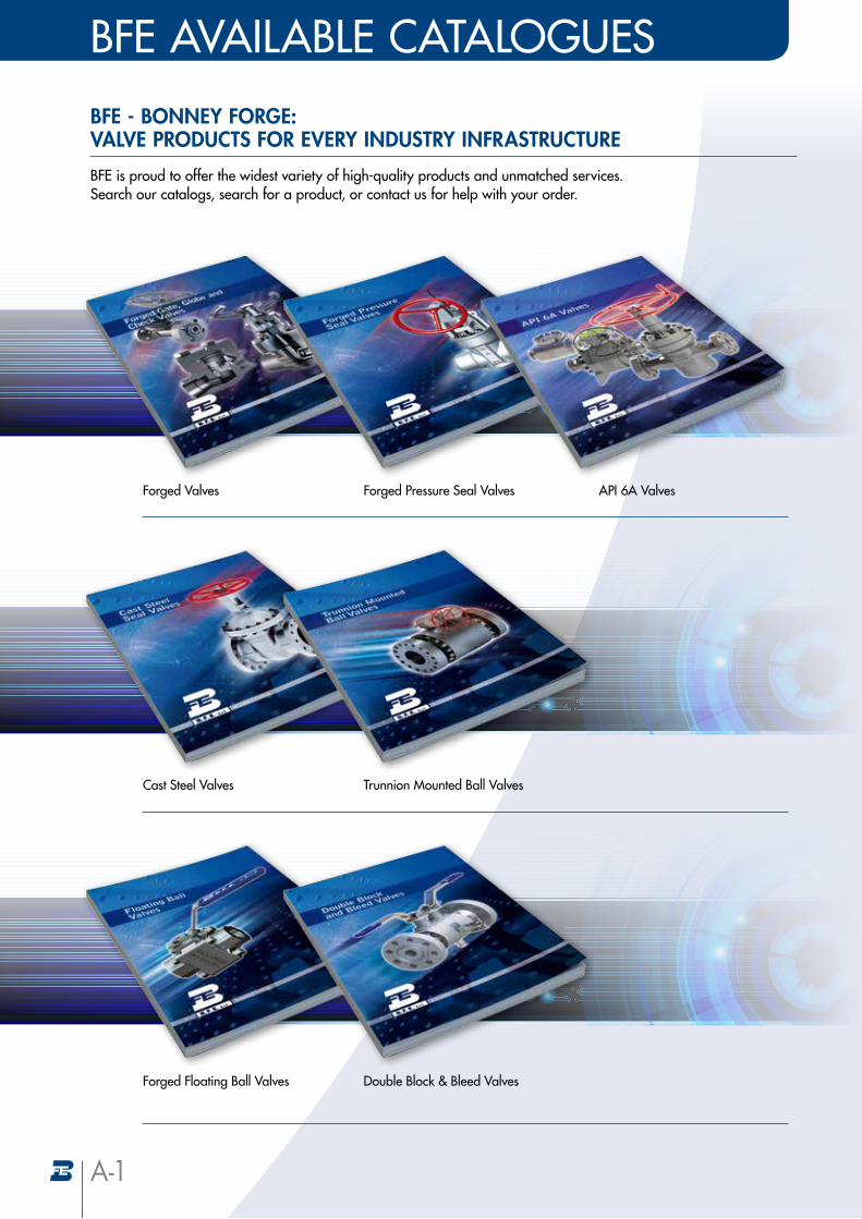
BFE - BONNEY FORGE: VALVE PRODUCTS FOR EVERY INDUSTRY INFRASTRUCTURE
BFE is proud to offer the widest variety of high-quality products and unmatched services. Search our catalogs, search for a product, or contact us for help with your order.
Forged Pressure Seal Valves API 6A ValvesForged Valves
Trunnion Mounted Ball ValvesCast Steel Valves
Double Block & Bleed ValvesForged Floating Ball Valves
A-1
A-2
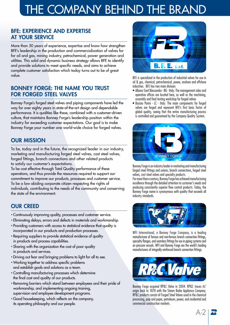
BFE: EXPERIENCE AND EXPERTISE AT YOUR SERVICE More than 50 years of experience, expertise and know how strengthen BFE’s leadership in the production and commercialization of valves for for oil and gas, mining industry, petrochemical, power generation and utilities. This solid and dynamic business strategy allows BFE to identify and provide solutions to meet specific needs, and aims to achieve complete customer satisfaction which today turns out to be of great value.
THE COMPANY BEHIND THE BRAND
BFE is specialized in the production of industrial valves for use in oil & gas, chemical, petrochemical, power, onshore and offshore industries. BFE has two main division: • Albano Sant’Alessandro - BG - Italy: The management sales and
operative offices are located here, as well as the machining, assembly and final testing workshop for forged valves
• Bosisio Parini - LC - Italy: The main components for forged valves are forged and represent BFE’s first basic factor of global quality, seeing that the entire manufacturing process is controlled and guaranteed by the Company Quality System.
Bonney Forge is an industry leader in marketing and manufacturing forged steel fittings and unions, branch connections, forged steel valves, cast steel valves and specialty products. For more than a century, Bonney Forge has achieved manufacturing excellence through the detailed attention to customer’s needs and producing consistently superior flow control products. Today, the Bonney Forge name is synonymous with quality that exceeds all industry standards.
WFI International, a Bonney Forge Company, is a leading manufacturer of ferrous and non-ferrous branch connection fittings, specialty flanges, and seamless fittings for use in piping systems and on pressure vessels. WFI and Bonney Forge are the world’s leading manufacturers of integrally reinforced branch connection fittings.
BONNEY FORGE: THE NAME YOU TRUST FOR FORGED STEEL VALVESBonney Forge’s forged steel valves and piping components have led the way for over eighty years in state-of-the-art design and dependable performance. It is qualities like these, combined with a customer-driven culture, that maintains Bonney Forge’s leadership position within the industry for exceeding customer expectations. Our goal is to make Bonney Forge your number one world-wide choice for forged valves.
OUR MISSIONTo be, today and in the future, the recognized leader in our industry, marketing and manufacturing forged steel valves, cast steel valves, forged fittings, branch connections and other related products to satisfy our customer’s expectations. To be cost effective through Total Quality performance of these operations, and thus provide the resources required to support our commitment to improve our products, processes and customer service. To be a law abiding corporate citizen respecting the rights of individuals, contributing to the needs of the community and conserving the state of the environment.
OUR CREED• Continuously improving quality, processes and customer service.• Eliminating delays, errors and defects in materials and workmanship.• Providing customers with access to statistical evidence that quality is incorporated in our products and production processes.
• Requiring suppliers to provide statistical evidence of quality in products and process capabilities.
• Sharing with the organization the cost of poor quality in products and services.
• Driving out fear and bringing problems to light for all to see.• Working together to address specific problems and establish goals and solutions as a team.
• Controlling manufacturing processes which determine the final cost and quality of our products.
• Removing barriers which stand between employees and their pride of workmanship, and implementing ongoing training, supervision and employee development programs.
• Good housekeeping, which reflects on the company, its operating philosophy and our people.
Bonney Forge acquired RP&C Valve in 2004. RP&C traces its’ origin back to 1878 with the Steam Boiler Appliance Company. RP&C products consist of Forged Steel Valves used in the chemical processing, pulp and paper, petroleum, power, and residential and commercial construction markets.
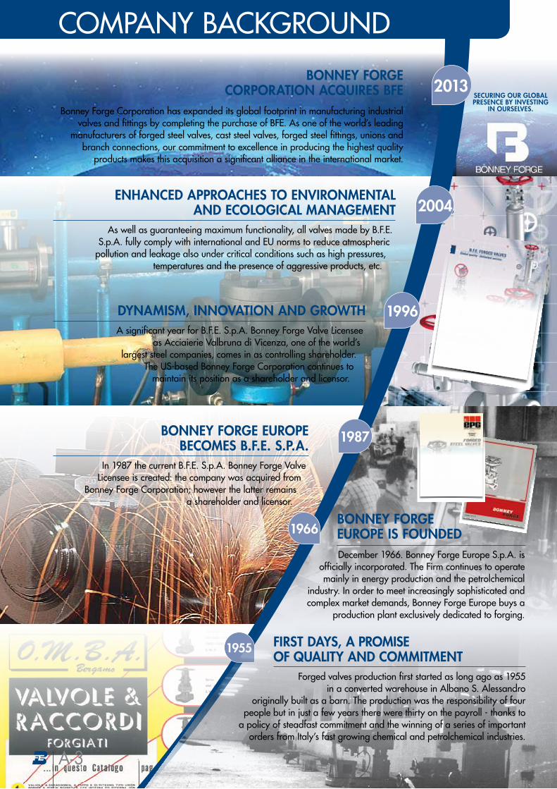
In 1987 the current B.F.E. S.p.A. Bonney Forge Valve Licensee is created: the company was acquired from
Bonney Forge Corporation; however the latter remains a shareholder and licensor.
BONNEY FORGE EUROPE BECOMES B.F.E. S.P.A.
A significant year for B.F.E. S.p.A. Bonney Forge Valve Licensee as Acciaierie Valbruna di Vicenza, one of the world’s
largest steel companies, comes in as controlling shareholder.The US-based Bonney Forge Corporation continues to
maintain its position as a shareholder and licensor.
DYNAMISM, INNOVATION AND GROWTH
As well as guaranteeing maximum functionality, all valves made by B.F.E. S.p.A. fully comply with international and EU norms to reduce atmospheric
pollution and leakage also under critical conditions such as high pressures, temperatures and the presence of aggressive products, etc.
ENHANCED APPROACHES TO ENVIRONMENTAL AND ECOLOGICAL MANAGEMENT
BONNEY FORGE CORPORATION ACQUIRES BFE
Bonney Forge Corporation has expanded its global footprint in manufacturing industrial valves and fittings by completing the purchase of BFE. As one of the world’s leading
manufacturers of forged steel valves, cast steel valves, forged steel fittings, unions and branch connections, our commitment to excellence in producing the highest quality
products makes this acquisition a significant alliance in the international market.
2004
2013
1987
1996
1966
1955
Forged valves production first started as long ago as 1955 in a converted warehouse in Albano S. Alessandro
originally built as a barn. The production was the responsibility of four people but in just a few years there were thirty on the payroll - thanks to
a policy of steadfast commitment and the winning of a series of important orders from Italy’s fast growing chemical and petrolchemical industries.
FIRST DAYS, A PROMISE OF QUALITY AND COMMITMENT
SECURING OUR GLOBALPRESENCE BY INVESTING
IN OURSELVES.
COMPANY BACKGROUND
BONNEY FORGE EUROPE IS FOUNDEDDecember 1966. Bonney Forge Europe S.p.A. is
officially incorporated. The Firm continues to operate mainly in energy production and the petrolchemical
industry. In order to meet increasingly sophisticated and complex market demands, Bonney Forge Europe buys a
production plant exclusively dedicated to forging.
A-3
COMPANY BACKGROUND
TAKING QUALITY TO THE NEXT LEVEL
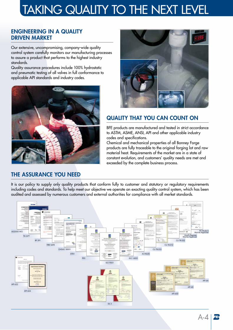
ENGINEERING IN A QUALITY DRIVEN MARKET
Our extensive, uncompromising, company-wide quality control system carefully monitors our manufacturing processes to assure a product that performs to the highest industry standards. Quality assurance procedures include 100% hydrostatic and pneumatic testing of all valves in full conformance to applicable API standards and industry codes.
QUALITY THAT YOU CAN COUNT ON
BFE products are manufactured and tested in strict accordance to ASTM, ASME, ANSI, API and other applicable industry codes and specifications. Chemical and mechanical properties of all Bonney Forge products are fully traceable to the original forging lot and raw material heat. Requirements of the market are in a state of constant evolution, and customers’ quality needs are met and exceeded by the complete business process.
THE ASSURANCE YOU NEED
It is our policy to supply only quality products that conform fully to customer and statutory or regulatory requirements including codes and standards. To help meet our objective we operate an exacting quality control system, which has been audited and assessed by numerous customers and external authorities for compliance with all merket standards.
A-4
AD2000 WO
TA LUFT
RP 591
FIRE SAFE
OHSAS 18001
ATEX
BV Mode II Marine Approval
Lloyd’s Register Marine Approval
CU TR-032
CU TR-012
CU TR-010
ACHILLES
ISO 14001
SIL 3
API 6A
API 6D
API 602
API 622
API 624
PED
ISO 9001
WHY FORGINGS?Forging offers uniformity of composition and structure. Forging results in metallurgical
recrystalisation and grain refinement as a result of the thermal cycle and deformation process. This strengthens the resulting steel product particularly in terms of impact and shear strength.
Forged steel is generally stronger and more reliable than castings and plate steel due to the fact that the grain flows of the steel are altered, conforming to the shape of the part.
CONFIDENCE IN STEEL FORGING
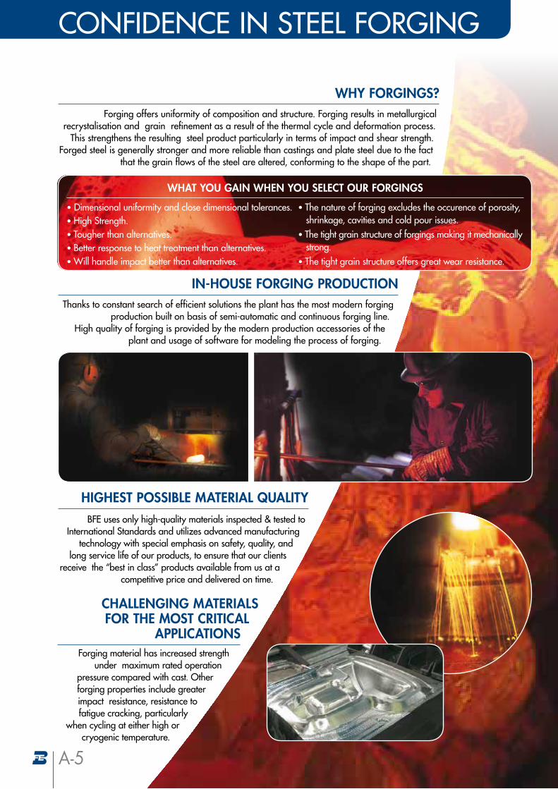
IN-HOUSE FORGING PRODUCTIONThanks to constant search of efficient solutions the plant has the most modern forging
production built on basis of semi-automatic and continuous forging line. High quality of forging is provided by the modern production accessories of the
plant and usage of software for modeling the process of forging.
HIGHEST POSSIBLE MATERIAL QUALITY BFE uses only high-quality materials inspected & tested to
International Standards and utilizes advanced manufacturing technology with special emphasis on safety, quality, and
long service life of our products, to ensure that our clients receive the “best in class” products available from us at a
competitive price and delivered on time.
Forging material has increased strength under maximum rated operation
pressure compared with cast. Other forging properties include greater impact resistance, resistance to fatigue cracking, particularly
when cycling at either high or cryogenic temperature.
• Dimensional uniformity and close dimensional tolerances. • High Strength. • Tougher than alternatives. • Better response to heat treatment than alternatives. • Will handle impact better than alternatives.
• The nature of forging excludes the occurence of porosity, shrinkage, cavities and cold pour issues.
• The tight grain structure of forgings making it mechanically strong.
• The tight grain structure offers great wear resistance.
WHAT YOU GAIN WHEN YOU SELECT OUR FORGINGS
A-5
CHALLENGING MATERIALS FOR THE MOST CRITICAL
APPLICATIONS
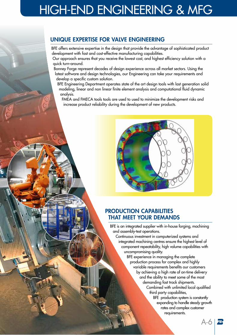
PRODUCTION CAPABILITIES THAT MEET YOUR DEMANDS
HIGH-END ENGINEERING & MFG
A-6
BFE offers extensive expertise in the design that provide the advantage of sophisticated product development with fast and cost-effective manufacturing capabilities. Our approach ensures that you receive the lowest cost, and highest efficiency solution with a quick turn-around. Bonney Forge represent decades of design experience across all market sectors. Using the latest software and design technologies, our Engineering can take your requirements and develop a specific custom solution. BFE Engineering Department operates state of the art design tools with last generation solid modeling, linear and non linear finite element analysis and computational fluid dynamic analysis. FMEA and FMECA tools tools are used to used to minimize the development risks and increase product reliability during the development of new products.
UNIQUE EXPERTISE FOR VALVE ENGINEERING
BFE is an integrated supplier with in-house forging, machining and assembly-test operations.
Continuous investment in computerized systems and integrated machining centres ensure the highest level of
component repeatability, high volume capabilities with uncompromising quality.
BFE experience in managing the complete production process for complex and highly
variable requirements benefits our customers by achieving a high rate of on-time delivery
and the ability to meet some of the most demanding fast track shipments.
Combined with unlimited local qualified third party capabilities,
BFE production system is constantly expanding to handle steady growth
rates and complex customer requirements.
A-7
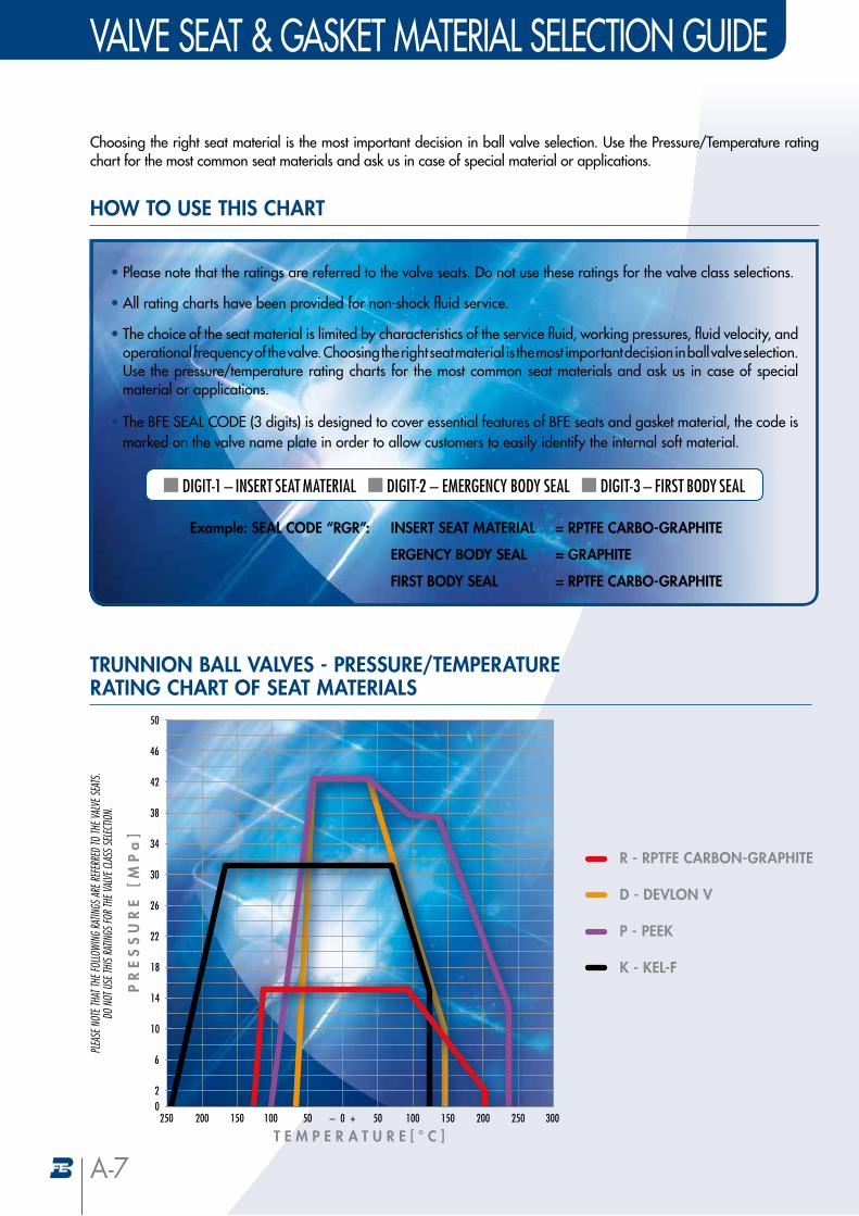
Choosing the right seat material is the most important decision in ball valve selection. Use the Pressure/Temperature rating chart for the most common seat materials and ask us in case of special material or applications.
HOW TO USE THIS CHART
TRUNNION BALL VALVES - PRESSURE/TEMPERATURE RATING CHART OF SEAT MATERIALS
• Please note that the ratings are referred to the valve seats. Do not use these ratings for the valve class selections.
• All rating charts have been provided for non-shock fluid service.
• The choice of the seat material is limited by characteristics of the service fluid, working pressures, fluid velocity, and operational frequency of the valve. Choosing the right seat material is the most important decision in ball valve selection. Use the pressure/temperature rating charts for the most common seat materials and ask us in case of special material or applications.
• The BFE SEAL CODE (3 digits) is designed to cover essential features of BFE seats and gasket material, the code is marked on the valve name plate in order to allow customers to easily identify the internal soft material.
DIGIT-1 – INSERT SEAT MATERIAL DIGIT-2 – EMERGENCY BODY SEAL DIGIT-3 – FIRST BODY SEAL
Example: SEAL CODE “RGR”: INSERT SEAT MATERIAL = RPTFE CARBO-GRAPHITE
ERGENCY BODY SEAL = GRAPHITE
FIRST BODY SEAL = RPTFE CARBO-GRAPHITE
PLEA
SE N
OTE T
HAT T
HE FO
LLOWI
NG RA
TINGS
ARE R
EFER
RED
TO TH
E VAL
VE SE
ATS.
DO N
OT U
SE TH
IS RA
TINGS
FOR T
HE VA
LVE C
LASS
SELEC
TION.
VALVE SEAT & GASKET MATERIAL SELECTION GUIDE
02
6
10
14
18
22
26
30
34
38
42
46
50
250 200 150 100 50 0 +– 50 100 150 200 250 300
PR
ES
SU
RE
[M
Pa
]
T E M P E R A T U R E [ ° C ]
R - RPTFE CARBON-GRAPHITE
D - DEVLON V
P - PEEK
K - KEL-F
A-8
SEAL MATERIAL MATERIALS CHARACTERISTICS BFE SYMBOL
AVAILABLE MATERIAL FOR
SEAT
AVAILABLE MATERIAL FOR
GASKETBFE SEAL CODE DIGIT 1 BFE SEAL CODE DIGIT 2/3
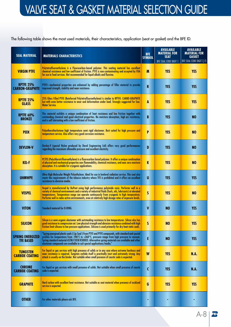
VIRGIN PTFEPolytetrafluoroethylene is a Fluorocarbon-based polymer. This seating material has excellent chemical resistance and low coefficient of friction. PTFE is non-contaminating and accepted by FDA for use in food services. Not recommended for liquid alkalis and fluorine.
M YES YES
RPTFE 25%CARBON-GRAPHITE
PTFE’s mechanical properties are enhanced by adding percentage of filler material to provide improved strength, stability and wear resistance. R YES YES
RPTFE 25%GLASS
25% Glass Filled PTFE (Reinforced Polytetrafluoroethylene) is similar to RPTFE- CARBO-GRAPHITE but with even better resistance to wear and deformation under load. Strongly suggested for Sea-Water Service.
A YES YES
RPTFE 60% BRONZE
This material exhibits a unique combination of heat resistance and low friction together with outstanding chemical and good electrical properties. No moisture absorption, high arc resistance, and is self lubricating with a low coefficient of friction.
B YES NO
PEEK Polyetheretherketone high temperature semi rigid elastomer. Best suited for high pressure and temperature service. Also offers very good corrosion resistance. P YES NO
DEVLON-V Devlon-V (special Nylon produced by Devol Engineering Ltd) offers very good performances regarding the maximum allowable pressure and excellent elasticity. D YES NO
KEL-FPCTFE (Polychlorotrifluoroethylene) is a fluorocarbon based polymer. It offers a unique combination of physical and mechanical properties non-flammability, chemical resistance, and near zero moisture absorption. It is suitable for cryogenic applications.
K YES NO
UHMWPEUltra-High Molecular Weight Polyethylene. Ideal for use in lowlevel radiation service. This seat also meets the requirements of the tobacco industry where TFE is prohibited and it offers an excellent resistance to abrasive media.
U YES YES
VESPELVespel is manufactured by DuPont using high performance polyimide resin. Performs well in a variety of chemical environments and a variety of industrial fluids (fuels, oils, lubricants) at elevated temperatures. Temperature range can operate continuously from cryogenic to high temperature. Performs well in radio-active environments, even at relatively high dosage rates of exposure levels.
S YES NO
VITON Standard material for O-RING. V NO YES
SILICONSilicon is a semi-organic elastomer with outstanding resistance to low temperatures. Silicon also has good resistance to compression set. Low physical strength and abrasion resistance combined with high friction limit silicone to low pressure applications. Silicone is used primarily for dry heat static seals.
S NO YES
SPRING ENERGIZED TFE BASED
"Spring energised plastic seals ( Lip-Seal ) from PTFE and PTFE compounds, with standard and special profiles for temperature from -196°C to +260°C, pressure range from high pressure to vacuum. Spring standard material ASTM F1058 R30003. Alternative spring materials are available and other elastomer compounds are available to suit special applications/media."
E NO YES
TUNGSTEN CARBIDE COATING
For liquid or gas services with high presence of solids or in any case where extreme hardness and wear resistance is required. Tungsten carbide itself is practically inert and extremely strong. Any attack is usually on the binder. Not suitable when small presence of caustic soda is expected.
W YES N.A.
CHROME CARBIDE COATING
For liquid or gas services with small presence of solids. Not suitable when small presence of caustic soda is expected. C YES N.A.
GRAPHITE Hard carbon with excellent heat resistance. Not suitable as seat material when presence of oxidized service is expected. G YES YES
OTHER For other materials please ask BFE. - - -
The following table shows the most used materials, their characteristics, application (seat or gasket) and the BFE ID.
VALVE SEAT & GASKET MATERIAL SELECTION GUIDE
BUTT WELDINGEND
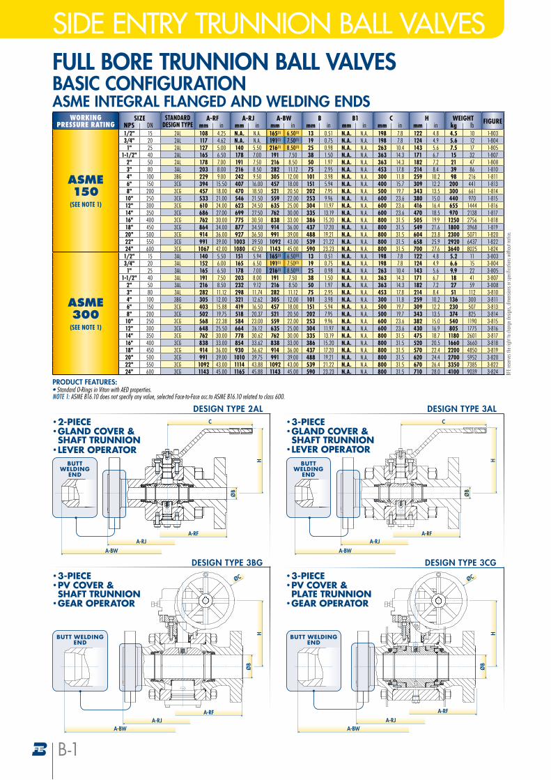
SIDE ENTRY TRUNNION BALL VALVESFULL BORE TRUNNION BALL VALVES BASIC CONFIGURATIONASME INTEGRAL FLANGED AND WELDING ENDS
WORKINGPRESSURE RATING
SIZE STANDARDDESIGN TYPE
A-RF A-RJ A-BW B B1 C H WEIGHT FIGURENPS DN mm in mm in mm in mm in mm in mm in mm in kg lb
ASME150
(SEE NOTE 1)
1/2" 15 2AL 108 4.25 N.A. N.A. 165(1) 6.50(1) 13 0.51 N.A. N.A. 198 7.8 122 4.8 4.5 10 1-8033/4" 20 2AL 117 4.62 N.A. N.A. 191(1) 7.50(1) 19 0.75 N.A. N.A. 198 7.8 124 4.9 5.6 12 1-8041" 25 2AL 127 5.00 140 5.50 216(1) 8.50(1) 25 0.98 N.A. N.A. 263 10.4 143 5.6 7.5 17 1-805
1-1/2" 40 2AL 165 6.50 178 7.00 191 7.50 38 1.50 N.A. N.A. 363 14.3 171 6.7 15 32 1-8072" 50 2AL 178 7.00 191 7.50 216 8.50 50 1.97 N.A. N.A. 363 14.3 182 7.2 21 47 1-8083" 80 3AL 203 8.00 216 8.50 282 11.12 75 2.95 N.A. N.A. 453 17.8 214 8.4 39 86 1-8104" 100 3BG 229 9.00 242 9.50 305 12.00 101 3.98 N.A. N.A. 300 11.8 259 10.2 98 216 1-8116" 150 3CG 394 15.50 407 16.00 457 18.00 151 5.94 N.A. N.A. 400 15.7 309 12.2 200 441 1-8138" 200 3CG 457 18.00 470 18.50 521 20.50 202 7.95 N.A. N.A. 500 19.7 343 13.5 300 661 1-81410" 250 3CG 533 21.00 546 21.50 559 22.00 253 9.96 N.A. N.A. 600 23.6 380 15.0 440 970 1-81512" 300 3CG 610 24.00 623 24.50 635 25.00 304 11.97 N.A. N.A. 600 23.6 416 16.4 655 1444 1-81614" 350 3CG 686 27.00 699 27.50 762 30.00 335 13.19 N.A. N.A. 600 23.6 470 18.5 970 2138 1-81716" 400 3CG 762 30.00 775 30.50 838 33.00 386 15.20 N.A. N.A. 800 31.5 505 19.9 1250 2756 1-81818" 450 3CG 864 34.00 877 34.50 914 36.00 437 17.20 N.A. N.A. 800 31.5 549 21.6 1800 3968 1-81920" 500 3CG 914 36.00 927 36.50 991 39.00 488 19.21 N.A. N.A. 800 31.5 604 23.8 2300 5071 1-82022" 550 3CG 991 39.00 1003 39.50 1092 43.00 539 21.22 N.A. N.A. 800 31.5 658 25.9 2920 6437 1-82224" 600 3CG 1067 42.00 1080 42.50 1143 45.00 590 23.23 N.A. N.A. 800 31.5 700 27.6 3640 8025 1-824
ASME300
(SEE NOTE 1)
1/2" 15 3AL 140 5.50 151 5.94 165(1) 6.50(1) 13 0.51 N.A. N.A. 198 7.8 122 4.8 5.2 11 3-8033/4" 20 3AL 152 6.00 165 6.50 191(1) 7.50(1) 19 0.75 N.A. N.A. 198 7.8 124 4.9 6.6 15 3-8041" 25 3AL 165 6.50 178 7.00 216(1) 8.50(1) 25 0.98 N.A. N.A. 263 10.4 143 5.6 9.9 22 3-805
1-1/2" 40 3AL 191 7.50 203 8.00 191 7.50 38 1.50 N.A. N.A. 363 14.3 171 6.7 18 41 3-8072" 50 3AL 216 8.50 232 9.12 216 8.50 50 1.97 N.A. N.A. 363 14.3 182 7.2 27 59 3-8083" 80 3AL 282 11.12 298 11.74 282 11.12 75 2.95 N.A. N.A. 453 17.8 214 8.4 51 112 3-8104" 100 3BG 305 12.00 321 12.62 305 12.00 101 3.98 N.A. N.A. 300 11.8 259 10.2 136 300 3-8116" 150 3CG 403 15.88 419 16.50 457 18.00 151 5.94 N.A. N.A. 500 19.7 309 12.2 230 507 3-8138" 200 3CG 502 19.75 518 20.37 521 20.50 202 7.95 N.A. N.A. 500 19.7 343 13.5 374 825 3-81410" 250 3CG 568 22.38 584 23.00 559 22.00 253 9.96 N.A. N.A. 600 23.6 382 15.0 540 1190 3-81512" 300 3CG 648 25.50 664 26.12 635 25.00 304 11.97 N.A. N.A. 600 23.6 430 16.9 805 1775 3-81614" 350 3CG 762 30.00 778 30.62 762 30.00 335 13.19 N.A. N.A. 800 31.5 475 18.7 1180 2601 3-81716" 400 3CG 838 33.00 854 33.62 838 33.00 386 15.20 N.A. N.A. 800 31.5 520 20.5 1660 3660 3-81818" 450 3CG 914 36.00 930 36.62 914 36.00 437 17.20 N.A. N.A. 800 31.5 570 22.4 2200 4850 3-81920" 500 3CG 991 39.00 1010 39.75 991 39.00 488 19.21 N.A. N.A. 800 31.5 620 24.4 2700 5952 3-82022" 550 3CG 1092 43.00 1114 43.88 1092 43.00 539 21.22 N.A. N.A. 800 31.5 670 26.4 3350 7385 3-82224" 600 3CG 1143 45.00 1165 45.88 1143 45.00 590 23.23 N.A. N.A. 800 31.5 710 28.0 4100 9039 3-824
PRODUCT FEATURES:• Standard O-Rings in Viton with AED properties. NOTE 1: ASME B16.10 does not specify any value, selected Face-to-Face acc.to ASME B16.10 related to class 600.
BFE r
eser
ves t
he ri
ght t
o cha
nge d
esign
s, dim
ensio
ns or
spec
ifica
tions
with
out n
otice
.
• 3-PIECE• PV COVER & SHAFT TRUNNION
• GEAR OPERATOR
DESIGN TYPE 3BG
ØB
H
A-RJA-RF
ØC
A-BW
• 2-PIECE• GLAND COVER & SHAFT TRUNNION
• LEVER OPERATOR
DESIGN TYPE 2AL
ØB
H
A-RJA-RF
C
BUTT WELDING
END
A-BW
BUTT WELDING
END
A-RJA-RF
A-BW
• 3-PIECE• GLAND COVER & SHAFT TRUNNION
• LEVER OPERATOR
DESIGN TYPE 3AL
ØB
C
H
• 3-PIECE• PV COVER & PLATE TRUNNION
• GEAR OPERATOR
DESIGN TYPE 3CG
ØB
H
A-RJ
A-RF
ØC
BUTT WELDINGEND
A-BW
B-1
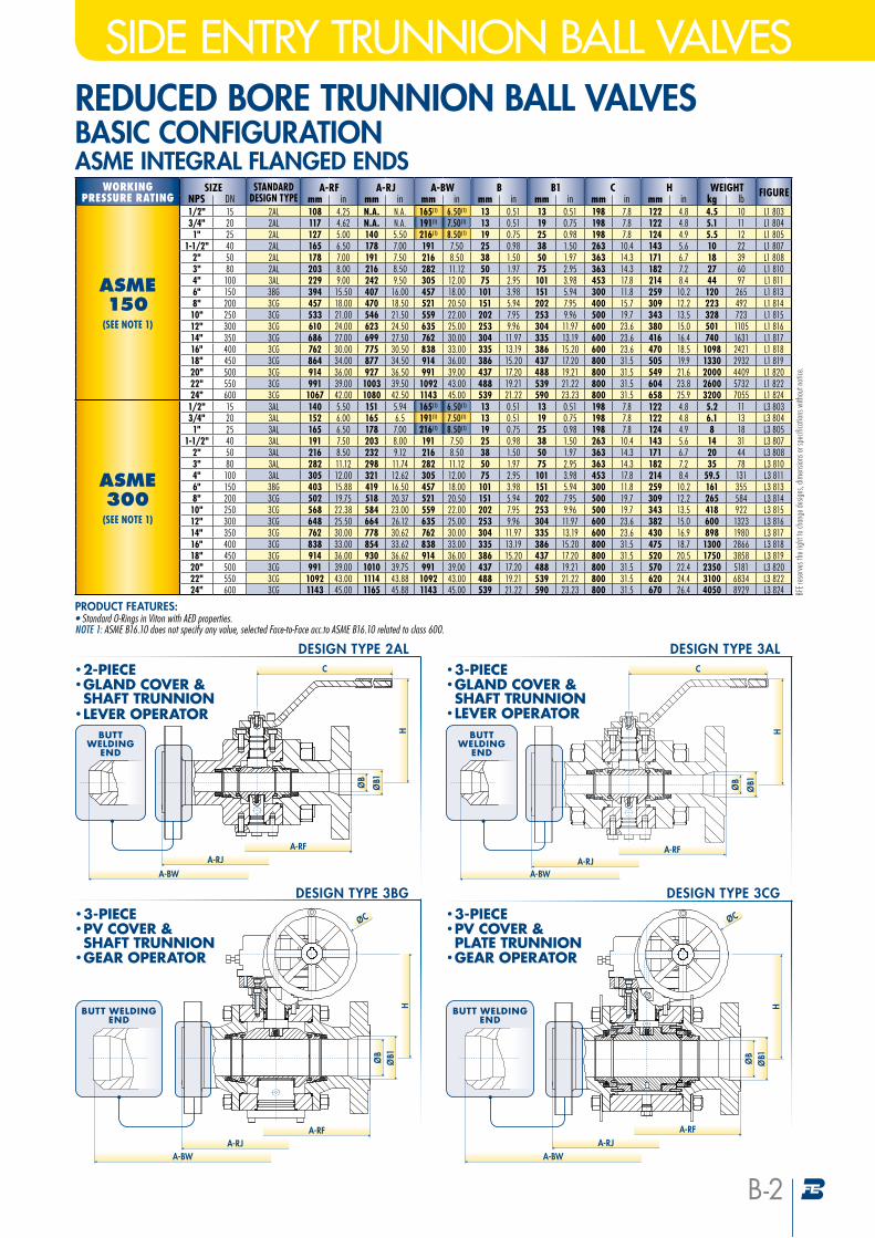
SIDE ENTRY TRUNNION BALL VALVESREDUCED BORE TRUNNION BALL VALVES BASIC CONFIGURATIONASME INTEGRAL FLANGED ENDS
WORKINGPRESSURE RATING
SIZE STANDARDDESIGN TYPE
A-RF A-RJ A-BW B B1 C H WEIGHT FIGURENPS DN mm in mm in mm in mm in mm in mm in mm in kg lb
ASME150
(SEE NOTE 1)
1/2" 15 2AL 108 4.25 N.A. N.A. 165(1) 6.50(1) 13 0.51 13 0.51 198 7.8 122 4.8 4.5 10 L1 8033/4" 20 2AL 117 4.62 N.A. N.A. 191(1) 7.50(1) 13 0.51 19 0.75 198 7.8 122 4.8 5.1 11 L1 8041" 25 2AL 127 5.00 140 5.50 216(1) 8.50(1) 19 0.75 25 0.98 198 7.8 124 4.9 5.5 12 L1 805
1-1/2" 40 2AL 165 6.50 178 7.00 191 7.50 25 0.98 38 1.50 263 10.4 143 5.6 10 22 L1 8072" 50 2AL 178 7.00 191 7.50 216 8.50 38 1.50 50 1.97 363 14.3 171 6.7 18 39 L1 8083" 80 2AL 203 8.00 216 8.50 282 11.12 50 1.97 75 2.95 363 14.3 182 7.2 27 60 L1 8104" 100 3AL 229 9.00 242 9.50 305 12.00 75 2.95 101 3.98 453 17.8 214 8.4 44 97 L1 8116" 150 3BG 394 15.50 407 16.00 457 18.00 101 3.98 151 5.94 300 11.8 259 10.2 120 265 L1 8138" 200 3CG 457 18.00 470 18.50 521 20.50 151 5.94 202 7.95 400 15.7 309 12.2 223 492 L1 81410" 250 3CG 533 21.00 546 21.50 559 22.00 202 7.95 253 9.96 500 19.7 343 13.5 328 723 L1 81512" 300 3CG 610 24.00 623 24.50 635 25.00 253 9.96 304 11.97 600 23.6 380 15.0 501 1105 L1 81614" 350 3CG 686 27.00 699 27.50 762 30.00 304 11.97 335 13.19 600 23.6 416 16.4 740 1631 L1 81716" 400 3CG 762 30.00 775 30.50 838 33.00 335 13.19 386 15.20 600 23.6 470 18.5 1098 2421 L1 81818" 450 3CG 864 34.00 877 34.50 914 36.00 386 15.20 437 17.20 800 31.5 505 19.9 1330 2932 L1 81920" 500 3CG 914 36.00 927 36.50 991 39.00 437 17.20 488 19.21 800 31.5 549 21.6 2000 4409 L1 82022" 550 3CG 991 39.00 1003 39.50 1092 43.00 488 19.21 539 21.22 800 31.5 604 23.8 2600 5732 L1 82224" 600 3CG 1067 42.00 1080 42.50 1143 45.00 539 21.22 590 23.23 800 31.5 658 25.9 3200 7055 L1 824
ASME300
(SEE NOTE 1)
1/2" 15 3AL 140 5.50 151 5.94 165(1) 6.50(1) 13 0.51 13 0.51 198 7.8 122 4.8 5.2 11 L3 8033/4" 20 3AL 152 6.00 165 6.5 191(1) 7.50(1) 13 0.51 19 0.75 198 7.8 122 4.8 6.1 13 L3 8041" 25 3AL 165 6.50 178 7.00 216(1) 8.50(1) 19 0.75 25 0.98 198 7.8 124 4.9 8 18 L3 805
1-1/2" 40 3AL 191 7.50 203 8.00 191 7.50 25 0.98 38 1.50 263 10.4 143 5.6 14 31 L3 8072" 50 3AL 216 8.50 232 9.12 216 8.50 38 1.50 50 1.97 363 14.3 171 6.7 20 44 L3 8083" 80 3AL 282 11.12 298 11.74 282 11.12 50 1.97 75 2.95 363 14.3 182 7.2 35 78 L3 8104" 100 3AL 305 12.00 321 12.62 305 12.00 75 2.95 101 3.98 453 17.8 214 8.4 59.5 131 L3 8116" 150 3BG 403 15.88 419 16.50 457 18.00 101 3.98 151 5.94 300 11.8 259 10.2 161 355 L3 8138" 200 3CG 502 19.75 518 20.37 521 20.50 151 5.94 202 7.95 500 19.7 309 12.2 265 584 L3 81410" 250 3CG 568 22.38 584 23.00 559 22.00 202 7.95 253 9.96 500 19.7 343 13.5 418 922 L3 81512" 300 3CG 648 25.50 664 26.12 635 25.00 253 9.96 304 11.97 600 23.6 382 15.0 600 1323 L3 81614" 350 3CG 762 30.00 778 30.62 762 30.00 304 11.97 335 13.19 600 23.6 430 16.9 898 1980 L3 81716" 400 3CG 838 33.00 854 33.62 838 33.00 335 13.19 386 15.20 800 31.5 475 18.7 1300 2866 L3 81818" 450 3CG 914 36.00 930 36.62 914 36.00 386 15.20 437 17.20 800 31.5 520 20.5 1750 3858 L3 81920" 500 3CG 991 39.00 1010 39.75 991 39.00 437 17.20 488 19.21 800 31.5 570 22.4 2350 5181 L3 82022" 550 3CG 1092 43.00 1114 43.88 1092 43.00 488 19.21 539 21.22 800 31.5 620 24.4 3100 6834 L3 82224" 600 3CG 1143 45.00 1165 45.88 1143 45.00 539 21.22 590 23.23 800 31.5 670 26.4 4050 8929 L3 824
PRODUCT FEATURES:• Standard O-Rings in Viton with AED properties. NOTE 1: ASME B16.10 does not specify any value, selected Face-to-Face acc.to ASME B16.10 related to class 600.
BFE r
eser
ves t
he ri
ght t
o cha
nge d
esign
s, dim
ensio
ns or
spec
ifica
tions
with
out n
otice
.
• 2-PIECE• GLAND COVER & SHAFT TRUNNION
• LEVER OPERATOR
DESIGN TYPE 2AL
BUTT WELDING
END
ØB
ØB1
H
A-RJA-RF
C
A-BW
BUTT WELDING
ENDØ
B1ØB
A-RJA-RF
C
H
A-BW
• 3-PIECE• GLAND COVER & SHAFT TRUNNION
• LEVER OPERATOR
DESIGN TYPE 3AL
BUTT WELDINGEND
DESIGN TYPE 3BG
ØB1ØB
H
A-RJA-RF
ØC• 3-PIECE• PV COVER & SHAFT TRUNNION
• GEAR OPERATOR
A-BW
• 3-PIECE• PV COVER & PLATE TRUNNION
• GEAR OPERATOR
DESIGN TYPE 3CG
BUTT WELDINGEND
ØB1ØB
H
A-RJA-RF
ØC
A-BW
B-2
SIDE ENTRY TRUNNION BALL VALVES
WORKINGPRESSURE RATING
SIZE STANDARDDESIGN TYPE
A-RF A-RJ A-BW B B1 C H WEIGHT FIGURENPS DN mm in mm in mm in mm in mm in mm in mm in kg lb
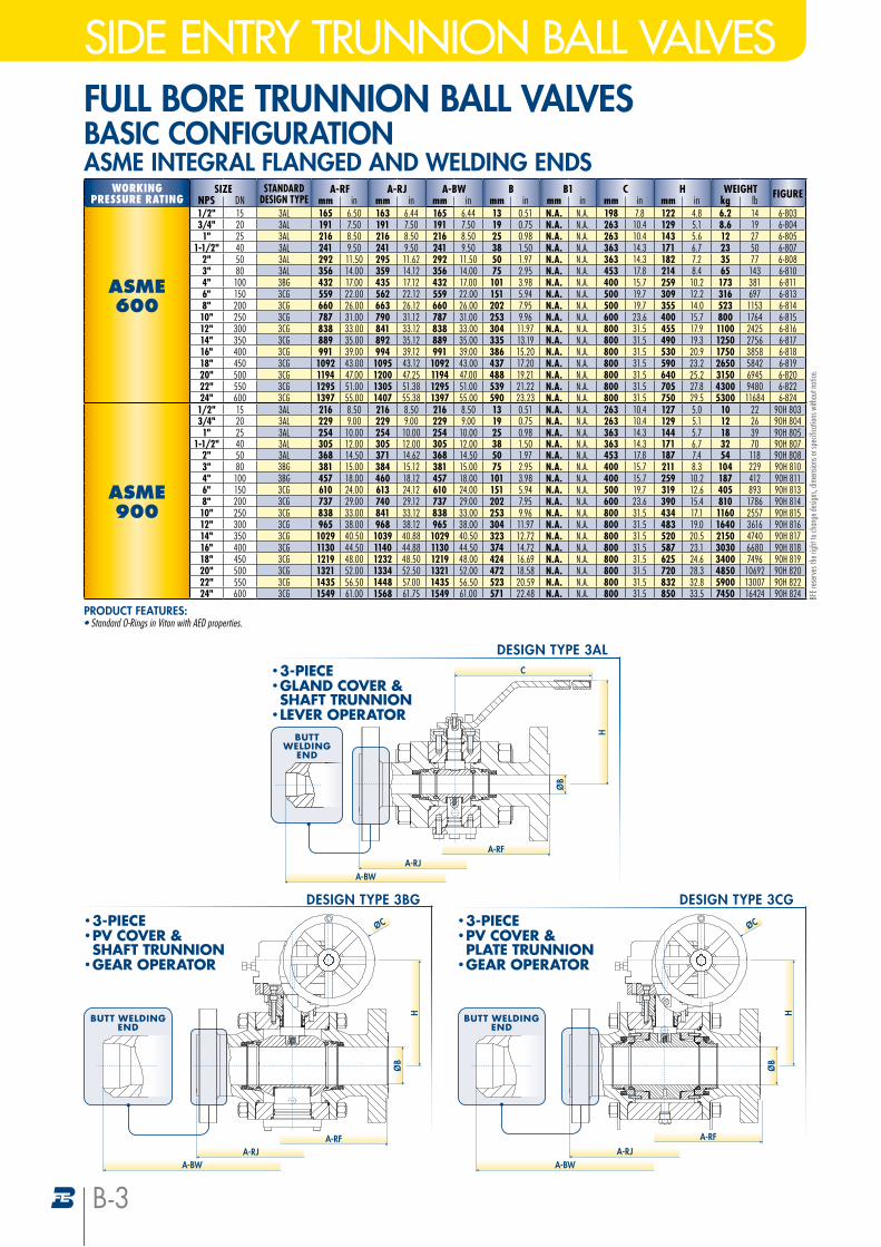
ASME600
1/2" 15 3AL 165 6.50 163 6.44 165 6.44 13 0.51 N.A. N.A. 198 7.8 122 4.8 6.2 14 6-8033/4" 20 3AL 191 7.50 191 7.50 191 7.50 19 0.75 N.A. N.A. 263 10.4 129 5.1 8.6 19 6-8041" 25 3AL 216 8.50 216 8.50 216 8.50 25 0.98 N.A. N.A. 263 10.4 143 5.6 12 27 6-805
1-1/2" 40 3AL 241 9.50 241 9.50 241 9.50 38 1.50 N.A. N.A. 363 14.3 171 6.7 23 50 6-8072" 50 3AL 292 11.50 295 11.62 292 11.50 50 1.97 N.A. N.A. 363 14.3 182 7.2 35 77 6-8083" 80 3AL 356 14.00 359 14.12 356 14.00 75 2.95 N.A. N.A. 453 17.8 214 8.4 65 143 6-8104" 100 3BG 432 17.00 435 17.12 432 17.00 101 3.98 N.A. N.A. 400 15.7 259 10.2 173 381 6-8116" 150 3CG 559 22.00 562 22.12 559 22.00 151 5.94 N.A. N.A. 500 19.7 309 12.2 316 697 6-8138" 200 3CG 660 26.00 663 26.12 660 26.00 202 7.95 N.A. N.A. 500 19.7 355 14.0 523 1153 6-81410" 250 3CG 787 31.00 790 31.12 787 31.00 253 9.96 N.A. N.A. 600 23.6 400 15.7 800 1764 6-81512" 300 3CG 838 33.00 841 33.12 838 33.00 304 11.97 N.A. N.A. 800 31.5 455 17.9 1100 2425 6-81614" 350 3CG 889 35.00 892 35.12 889 35.00 335 13.19 N.A. N.A. 800 31.5 490 19.3 1250 2756 6-81716" 400 3CG 991 39.00 994 39.12 991 39.00 386 15.20 N.A. N.A. 800 31.5 530 20.9 1750 3858 6-81818" 450 3CG 1092 43.00 1095 43.12 1092 43.00 437 17.20 N.A. N.A. 800 31.5 590 23.2 2650 5842 6-81920" 500 3CG 1194 47.00 1200 47.25 1194 47.00 488 19.21 N.A. N.A. 800 31.5 640 25.2 3150 6945 6-82022" 550 3CG 1295 51.00 1305 51.38 1295 51.00 539 21.22 N.A. N.A. 800 31.5 705 27.8 4300 9480 6-82224" 600 3CG 1397 55.00 1407 55.38 1397 55.00 590 23.23 N.A. N.A. 800 31.5 750 29.5 5300 11684 6-824
ASME900
1/2" 15 3AL 216 8.50 216 8.50 216 8.50 13 0.51 N.A. N.A. 263 10.4 127 5.0 10 22 90H 8033/4" 20 3AL 229 9.00 229 9.00 229 9.00 19 0.75 N.A. N.A. 263 10.4 129 5.1 12 26 90H 8041" 25 3AL 254 10.00 254 10.00 254 10.00 25 0.98 N.A. N.A. 363 14.3 144 5.7 18 39 90H 805
1-1/2" 40 3AL 305 12.00 305 12.00 305 12.00 38 1.50 N.A. N.A. 363 14.3 171 6.7 32 70 90H 8072" 50 3AL 368 14.50 371 14.62 368 14.50 50 1.97 N.A. N.A. 453 17.8 187 7.4 54 118 90H 8083" 80 3BG 381 15.00 384 15.12 381 15.00 75 2.95 N.A. N.A. 400 15.7 211 8.3 104 229 90H 8104" 100 3BG 457 18.00 460 18.12 457 18.00 101 3.98 N.A. N.A. 400 15.7 259 10.2 187 412 90H 8116" 150 3CG 610 24.00 613 24.12 610 24.00 151 5.94 N.A. N.A. 500 19.7 319 12.6 405 893 90H 8138" 200 3CG 737 29.00 740 29.12 737 29.00 202 7.95 N.A. N.A. 600 23.6 390 15.4 810 1786 90H 81410" 250 3CG 838 33.00 841 33.12 838 33.00 253 9.96 N.A. N.A. 800 31.5 434 17.1 1160 2557 90H 81512" 300 3CG 965 38.00 968 38.12 965 38.00 304 11.97 N.A. N.A. 800 31.5 483 19.0 1640 3616 90H 81614" 350 3CG 1029 40.50 1039 40.88 1029 40.50 323 12.72 N.A. N.A. 800 31.5 520 20.5 2150 4740 90H 81716" 400 3CG 1130 44.50 1140 44.88 1130 44.50 374 14.72 N.A. N.A. 800 31.5 587 23.1 3030 6680 90H 81818" 450 3CG 1219 48.00 1232 48.50 1219 48.00 424 16.69 N.A. N.A. 800 31.5 625 24.6 3400 7496 90H 81920" 500 3CG 1321 52.00 1334 52.50 1321 52.00 472 18.58 N.A. N.A. 800 31.5 720 28.3 4850 10692 90H 82022" 550 3CG 1435 56.50 1448 57.00 1435 56.50 523 20.59 N.A. N.A. 800 31.5 832 32.8 5900 13007 90H 82224" 600 3CG 1549 61.00 1568 61.75 1549 61.00 571 22.48 N.A. N.A. 800 31.5 850 33.5 7450 16424 90H 824
FULL BORE TRUNNION BALL VALVES BASIC CONFIGURATIONASME INTEGRAL FLANGED AND WELDING ENDS
PRODUCT FEATURES:• Standard O-Rings in Viton with AED properties.
BFE r
eser
ves t
he ri
ght t
o cha
nge d
esign
s, dim
ensio
ns or
spec
ifica
tions
with
out n
otice
.
BUTT WELDINGEND
• 3-PIECE• PV COVER & SHAFT TRUNNION
• GEAR OPERATOR
DESIGN TYPE 3BG
ØB
H
A-RJA-RF
ØC
A-BW
BUTT WELDING
END
A-RJA-RF
A-BW
• 3-PIECE• GLAND COVER & SHAFT TRUNNION
• LEVER OPERATOR
DESIGN TYPE 3AL
ØB
C
H
• 3-PIECE• PV COVER & PLATE TRUNNION
• GEAR OPERATOR
DESIGN TYPE 3CG
ØB
H
A-RJ
A-RF
ØC
BUTT WELDINGEND
A-BW
B-3
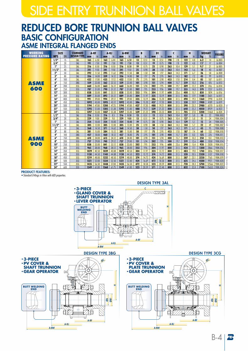
SIDE ENTRY TRUNNION BALL VALVESREDUCED BORE TRUNNION BALL VALVES BASIC CONFIGURATIONASME INTEGRAL FLANGED ENDS
WORKINGPRESSURE RATING
SIZE STANDARDDESIGN TYPE
A-RF A-RJ A-BW B B1 C H WEIGHT FIGURENPS DN mm in mm in mm in mm in mm in mm in mm in kg lb
ASME600
1/2" 15 3AL 165 6.50 163 6.44 165 6.50 13 0.51 13 0.51 198 7.8 122 4.8 6.2 14 L6 8033/4" 20 3AL 191 7.50 191 7.50 191 7.50 13 0.51 19 0.75 198 7.8 122 4.8 7.7 17 L6 8041" 25 3AL 216 8.50 216 8.50 216 8.50 19 0.75 25 0.98 263 10.4 129 5.1 9.7 21 L6 805
1-1/2" 40 3AL 241 9.50 241 9.50 241 9.50 25 0.98 38 1.50 263 10.4 143 5.6 18 40 L6 8072" 50 3AL 292 11.50 295 11.62 292 11.50 38 1.50 50 1.97 363 14.3 171 6.7 26 58 L6 8083" 80 3AL 356 14.00 359 14.12 356 14.00 50 1.97 75 2.95 363 14.3 182 7.2 45 99 L6 8104" 100 3AL 432 17.00 435 17.12 432 17.00 75 2.95 101 3.98 453 17.8 214 8.4 85 187 L6 8116" 150 3BG 559 22.00 562 22.12 559 22.00 101 3.98 151 5.94 400 15.7 259 10.2 216 476 L6 8138" 200 3CG 660 26.00 663 26.12 660 26.00 151 5.94 202 7.95 500 19.7 309 12.2 370 816 L6 81410" 250 3CG 787 31.00 790 31.12 787 31.00 202 7.95 253 9.96 500 19.7 355 14.0 570 1257 L6 81512" 300 3CG 838 33.00 841 33.12 838 33.00 253 9.96 304 11.97 600 23.6 400 15.7 850 1874 L6 81614" 350 3CG 889 35.00 892 35.12 889 35.00 304 11.97 335 13.19 800 31.5 455 17.9 1180 2601 L6 81716" 400 3CG 991 39.00 994 39.12 991 39.00 335 13.19 386 15.20 800 31.5 490 19.3 1360 2998 L6 81818" 450 3CG 1092 43.00 1095 43.12 1092 43.00 386 15.20 437 17.20 800 31.5 530 20.9 1900 4189 L6 81920" 500 3CG 1194 47.00 1200 47.25 1194 47.00 437 17.20 488 19.21 800 31.5 590 23.2 2980 6570 L6 82022" 550 3CG 1295 51.00 1305 51.38 1295 51.00 488 19.21 539 21.22 800 31.5 640 25.2 4050 8929 L6 82224" 600 3CG 1397 55.00 1407 55.38 1397 55.00 539 21.22 590 23.23 800 31.5 705 27.8 5200 11464 L6 824
ASME900
1/2" 15 3AL 216 8.50 216 8.5 216 8.50 13 0.51 13 0.51 263 10.4 127 5.0 10 22 90HL 8033/4" 20 3AL 229 9.00 229 9.0 229 9.00 13 0.51 19 0.75 263 10.4 127 5.0 11 24 90HL 8041" 25 3AL 254 10.00 254 10.00 254 10.00 19 0.75 25 0.98 263 10.4 129 5.1 15 34 90HL 805
1-1/2" 40 3AL 305 12.00 305 12.00 305 12.00 25 0.98 38 1.50 363 14.3 144 5.7 22 49 90HL 8072" 50 3AL 368 14.50 371 14.62 368 14.50 38 1.50 50 1.97 363 14.3 171 6.7 43 95 90HL 8083" 80 3AL 381 15.00 384 15.12 381 15.00 50 1.97 75 2.95 453 17.8 187 7.4 60 132 90HL 8104" 100 3BG 457 18.00 460 18.12 457 18.00 75 2.95 101 3.98 400 15.7 211 8.3 125 276 90HL 8116" 150 3BG 610 24.00 613 24.12 610 24.00 101 3.98 151 5.94 400 15.7 259 10.2 250 551 90HL 8138" 200 3CG 737 29.00 740 29.12 737 29.00 151 5.94 202 7.95 500 19.7 319 12.6 480 1058 90HL 81410" 250 3CG 838 33.00 841 33.12 838 33.00 202 7.95 253 9.96 600 23.6 390 15.4 920 2028 90HL 81512" 300 3CG 965 38.00 968 38.12 965 38.00 253 9.96 304 11.97 800 31.5 434 17.1 1300 2866 90HL 81614" 350 3CG 1029 40.50 1039 40.88 1029 40.50 304 11.97 323 12.72 800 31.5 483 19.0 1740 3836 90HL 81716" 400 3CG 1130 44.50 1140 44.88 1130 44.50 323 12.72 374 14.72 800 31.5 520 20.5 2330 5137 90HL 81818" 450 3CG 1219 48.00 1232 48.50 1219 48.00 374 14.72 424 16.69 800 31.5 587 23.1 3250 7165 90HL 81920" 500 3CG 1321 52.00 1334 52.50 1321 52.00 424 16.69 472 18.58 800 31.5 625 24.6 4500 9921 90HL 82022" 550 3CG 1435 56.50 1448 57.00 1435 56.50 472 18.58 523 20.59 800 31.5 720 28.3 5700 12566 90HL 82224" 600 3CG 1549 61.00 1568 61.75 1549 61.00 523 20.59 571 22.48 800 31.5 832 32.8 7100 15653 90HL 824
PRODUCT FEATURES:• Standard O-Rings in Viton with AED properties.
BUTT WELDING
END
ØB1ØB
A-RJA-RF
C
H
A-BW
• 3-PIECE• GLAND COVER & SHAFT TRUNNION
• LEVER OPERATOR
DESIGN TYPE 3AL
BUTT WELDINGEND
DESIGN TYPE 3BG
ØB1ØB
H
A-RJA-RF
ØC• 3-PIECE• PV COVER & SHAFT TRUNNION
• GEAR OPERATOR
A-BW
• 3-PIECE• PV COVER & PLATE TRUNNION
• GEAR OPERATOR
DESIGN TYPE 3CG
BUTT WELDINGEND
ØB1ØB
H
A-RJA-RF
ØC
A-BW
BFE r
eser
ves t
he ri
ght t
o cha
nge d
esign
s, dim
ensio
ns or
spec
ifica
tions
with
out n
otice
.
B-4
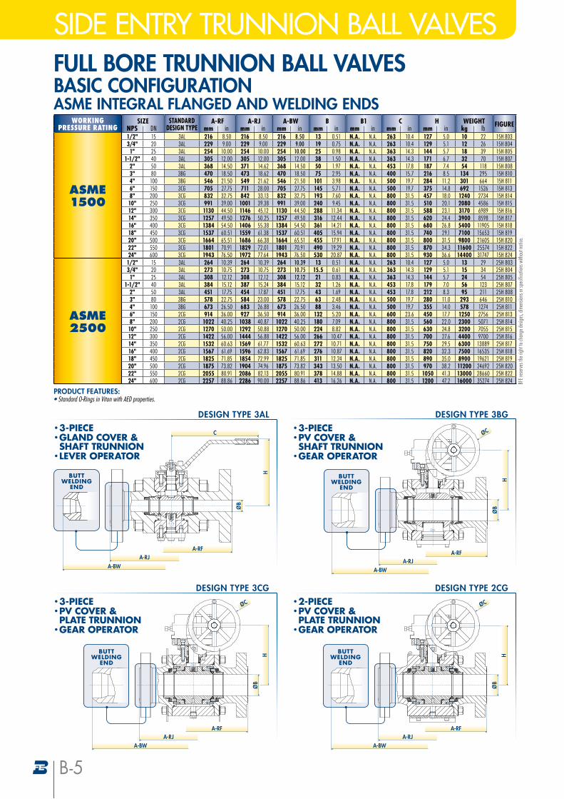
SIDE ENTRY TRUNNION BALL VALVESFULL BORE TRUNNION BALL VALVES BASIC CONFIGURATIONASME INTEGRAL FLANGED AND WELDING ENDS
WORKINGPRESSURE RATING
SIZE STANDARDDESIGN TYPE
A-RF A-RJ A-BW B B1 C H WEIGHT FIGURENPS DN mm in mm in mm in mm in mm in mm in mm in kg lb
ASME1500
1/2" 15 3AL 216 8.50 216 8.50 216 8.50 13 0.51 N.A. N.A. 263 10.4 127 5.0 10 22 15H 8033/4" 20 3AL 229 9.00 229 9.00 229 9.00 19 0.75 N.A. N.A. 263 10.4 129 5.1 12 26 15H 8041" 25 3AL 254 10.00 254 10.00 254 10.00 25 0.98 N.A. N.A. 363 14.3 144 5.7 18 39 15H 805
1-1/2" 40 3AL 305 12.00 305 12.00 305 12.00 38 1.50 N.A. N.A. 363 14.3 171 6.7 32 70 15H 8072" 50 3AL 368 14.50 371 14.62 368 14.50 50 1.97 N.A. N.A. 453 17.8 187 7.4 54 118 15H 8083" 80 3BG 470 18.50 473 18.62 470 18.50 75 2.95 N.A. N.A. 400 15.7 216 8.5 134 295 15H 8104" 100 3BG 546 21.50 549 21.62 546 21.50 101 3.98 N.A. N.A. 500 19.7 284 11.2 301 664 15H 8116" 150 3CG 705 27.75 711 28.00 705 27.75 145 5.71 N.A. N.A. 500 19.7 375 14.8 692 1526 15H 8138" 200 3CG 832 32.75 842 33.13 832 32.75 193 7.60 N.A. N.A. 800 31.5 457 18.0 1240 2734 15H 81410" 250 3CG 991 39.00 1001 39.38 991 39.00 240 9.45 N.A. N.A. 800 31.5 510 20.1 2080 4586 15H 81512" 300 3CG 1130 44.50 1146 45.12 1130 44.50 288 11.34 N.A. N.A. 800 31.5 588 23.1 3170 6989 15H 81614" 350 3CG 1257 49.50 1276 50.25 1257 49.50 316 12.44 N.A. N.A. 800 31.5 620 24.4 3900 8598 15H 81716" 400 3CG 1384 54.50 1406 55.38 1384 54.50 361 14.21 N.A. N.A. 800 31.5 680 26.8 5400 11905 15H 81818" 450 3CG 1537 60.51 1559 61.38 1537 60.51 405 15.94 N.A. N.A. 800 31.5 740 29.1 7100 15653 15H 81920" 500 3CG 1664 65.51 1686 66.38 1664 65.51 455 17.91 N.A. N.A. 800 31.5 800 31.5 9800 21605 15H 82022" 550 3CG 1801 70.91 1829 72.01 1801 70.91 490 19.29 N.A. N.A. 800 31.5 870 34.3 11600 25574 15H 82224" 600 3CG 1943 76.50 1972 77.64 1943 76.50 530 20.87 N.A. N.A. 800 31.5 930 36.6 14400 31747 15H 824
ASME2500
1/2" 15 3AL 264 10.39 264 10.39 264 10.39 13 0.51 N.A. N.A. 263 10.4 127 5.0 13 29 25H 8033/4" 20 3AL 273 10.75 273 10.75 273 10.75 15.5 0.61 N.A. N.A. 363 14.3 129 5.1 15 34 25H 8041" 25 3AL 308 12.12 308 12.12 308 12.12 21 0.83 N.A. N.A. 363 14.3 144 5.7 24 54 25H 805
1-1/2" 40 3AL 384 15.12 387 15.24 384 15.12 32 1.26 N.A. N.A. 453 17.8 179 7.0 56 123 25H 8072" 50 3AL 451 17.75 454 17.87 451 17.75 43 1.69 N.A. N.A. 453 17.8 212 8.3 95 211 25H 8083" 80 3BG 578 22.75 584 23.00 578 22.75 63 2.48 N.A. N.A. 500 19.7 280 11.0 293 646 25H 8104" 100 3BG 673 26.50 683 26.88 673 26.50 88 3.46 N.A. N.A. 500 19.7 355 14.0 578 1274 25H 8116" 150 2CG 914 36.00 927 36.50 914 36.00 132 5.20 N.A. N.A. 600 23.6 450 17.7 1250 2756 25H 8138" 200 2CG 1022 40.25 1038 40.87 1022 40.25 180 7.09 N.A. N.A. 800 31.5 560 22.0 2300 5071 25H 81410" 250 2CG 1270 50.00 1292 50.88 1270 50.00 224 8.82 N.A. N.A. 800 31.5 630 24.8 3200 7055 25H 81512" 300 2CG 1422 56.00 1444 56.88 1422 56.00 266 10.47 N.A. N.A. 800 31.5 700 27.6 4400 9700 25H 81614" 350 2CG 1532 60.63 1569 61.77 1532 60.63 272 10.71 N.A. N.A. 800 31.5 750 29.5 6300 13889 25H 81716" 400 2CG 1567 61.69 1596 62.83 1567 61.69 276 10.87 N.A. N.A. 800 31.5 820 32.3 7500 16535 25H 81818" 450 2CG 1825 71.85 1854 72.99 1825 71.85 311 12.24 N.A. N.A. 800 31.5 890 35.0 8900 19621 25H 81920" 500 2CG 1875 73.82 1904 74.96 1875 73.82 343 13.50 N.A. N.A. 800 31.5 970 38.2 11200 24692 25H 82022" 550 2CG 2055 80.91 2086 82.13 2055 80.91 378 14.88 N.A. N.A. 800 31.5 1050 41.3 13000 28660 25H 82224" 600 2CG 2257 88.86 2286 90.00 2257 88.86 413 16.26 N.A. N.A. 800 31.5 1200 47.2 16000 35274 25H 824 BF
E res
erve
s the
righ
t to c
hang
e des
igns,
dimen
sions
or sp
ecifi
catio
ns w
ithou
t not
ice.
PRODUCT FEATURES:• Standard O-Rings in Viton with AED properties.
BUTT WELDING
END
A-RF
A-BW
• 3-PIECE• GLAND COVER & SHAFT TRUNNION
• LEVER OPERATOR
DESIGN TYPE 3AL
ØB
C
H
A-RJ
• 3-PIECE• PV COVER & SHAFT TRUNNION
• GEAR OPERATOR
DESIGN TYPE 3BG
A-RF
ØC
A-RJ
ØB
BUTT WELDING
END
H
A-BW
• 2-PIECE• PV COVER & PLATE TRUNNION
• GEAR OPERATOR
DESIGN TYPE 2CG
ØC
ØB
H
A-RF
BUTT WELDING
END
A-BWA-RJ
• 3-PIECE• PV COVER & PLATE TRUNNION
• GEAR OPERATOR
DESIGN TYPE 3CG
ØC
ØB
H
A-RFA-RJ
BUTT WELDING
END
A-BW
B-5
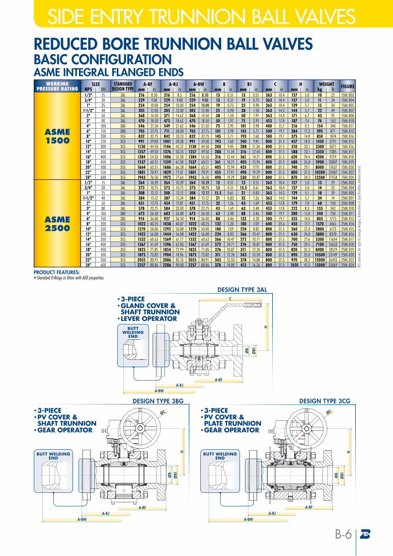
SIDE ENTRY TRUNNION BALL VALVESREDUCED BORE TRUNNION BALL VALVES BASIC CONFIGURATIONASME INTEGRAL FLANGED ENDS
WORKINGPRESSURE RATING
SIZE STANDARDDESIGN TYPE
A-RF A-RJ A-BW B B1 C H WEIGHT FIGURENPS DN mm in mm in mm in mm in mm in mm in mm in kg lb
ASME1500
1/2" 15 3AL 216 8.50 216 8.5 216 8.50 13 0.51 13 0.51 263 10.4 127 5.0 10 22 15HL 8033/4" 20 3AL 229 9.00 229 9.00 229 9.00 13 0.51 19 0.75 263 10.4 127 5.0 11 24 15HL 8041" 25 3AL 254 10.00 254 10.00 254 10.00 19 0.75 25 0.98 263 10.4 129 5.1 15 34 15HL 805
1-1/2" 40 3AL 305 12.00 305 12.00 305 12.00 25 0.98 38 1.50 363 14.3 144 5.7 22 49 15HL 8072" 50 3AL 368 14.50 371 14.62 368 14.50 38 1.50 50 1.97 363 14.3 171 6.7 43 95 15HL 8083" 80 3AL 470 18.50 473 18.62 470 18.50 50 1.97 75 2.95 453 17.8 187 7.4 74 163 15HL 8104" 100 3BG 546 21.50 549 21.62 546 21.50 75 2.95 101 3.98 400 15.7 216 8.5 154 340 15HL 8116" 150 3BG 705 27.75 711 28.00 705 27.75 101 3.98 145 5.71 500 19.7 284 11.2 395 871 15HL 8138" 200 3CG 832 32.75 842 33.13 832 32.75 145 5.71 193 7.60 500 19.7 375 14.8 850 1874 15HL 81410" 250 3CG 991 39.00 1001 39.38 991 39.00 193 7.60 240 9.45 800 31.5 457 18.0 1450 3197 15HL 81512" 300 3CG 1130 44.50 1146 45.12 1130 44.50 240 9.45 288 11.34 800 31.5 510 20.1 2300 5071 15HL 81614" 350 3CG 1257 49.50 1276 50.25 1257 49.50 288 11.34 316 12.44 800 31.5 588 23.1 3350 7385 15HL 81716" 400 3CG 1384 54.50 1406 55.38 1384 54.50 316 12.44 361 14.21 800 31.5 620 24.4 4200 9259 15HL 81818" 450 3CG 1537 60.51 1559 61.38 1537 60.51 361 14.21 405 15.94 800 31.5 680 26.8 5900 13007 15HL 81920" 500 3CG 1664 65.51 1686 66.38 1664 65.51 405 15.94 455 17.91 800 31.5 740 29.1 8000 17637 15HL 82022" 550 3CG 1801 70.91 1829 72.01 1801 70.91 455 17.91 490 19.29 800 31.5 800 31.5 10200 22487 15HL 82224" 600 3CG 1943 76.50 1972 77.64 1943 76.50 490 19.29 530 20.87 800 31.5 870 34.3 12500 27558 15HL 824
ASME2500
1/2" 15 3AL 264 10.39 264 10.39 264 10.39 13 0.51 13 0.51 263 10.4 127 5.0 13 29 25HL 8033/4" 20 3AL 273 10.75 273 10.75 273 10.75 13 0.51 15.5 0.61 263 10.4 127 5.0 14 32 25HL 8041" 25 3AL 308 12.12 308 12.12 308 12.12 15.5 0.61 21 0.83 363 14.3 129 5.1 18 39 25HL 805
1-1/2" 40 3AL 384 15.12 387 15.24 384 15.12 21 0.83 32 1.26 363 14.3 144 5.7 34 74 25HL 8072" 50 3AL 451 17.75 454 17.87 451 17.75 32 1.26 43 1.69 453 17.8 179 7.0 68 150 25HL 8083" 80 3AL 578 22.75 584 23.00 578 22.75 43 1.69 63 2.48 453 17.8 212 8.3 155 342 25HL 8104" 100 3BG 673 26.50 683 26.88 673 26.50 63 2.48 88 3.46 500 19.7 280 11.0 340 750 25HL 8116" 150 3BG 914 36.00 927 36.50 914 36.00 88 3.46 132 5.20 500 19.7 355 14.0 805 1775 25HL 8138" 200 3CG 1022 40.25 1038 40.87 1022 40.25 132 5.20 180 7.09 600 23.6 450 17.7 1570 3461 25HL 81410" 250 3CG 1270 50.00 1292 50.88 1270 50.00 180 7.09 224 8.82 800 31.5 560 22.0 2800 6173 25HL 81512" 300 3CG 1422 56.00 1444 56.88 1422 56.00 224 8.82 266 10.47 800 31.5 630 24.8 3800 8378 25HL 81614" 350 3CG 1532 60.63 1569 61.77 1532 60.63 266 10.47 272 10.71 800 31.5 700 27.6 5300 11684 25HL 81716" 400 3CG 1567 61.69 1596 62.83 1567 61.69 272 10.71 276 10.87 800 31.5 750 29.5 7100 15653 25HL 81818" 450 3CG 1825 71.85 1854 72.99 1825 71.85 276 10.87 311 12.24 800 31.5 820 32.3 8400 18519 25HL 81920" 500 3CG 1875 73.82 1904 74.96 1875 73.82 311 12.24 343 13.50 800 31.5 890 35.0 10500 23149 25HL 82022" 550 3CG 2055 80.91 2086 82.13 2055 80.91 343 13.50 378 14.88 800 31.5 970 38.2 12000 26455 25HL 82224" 600 3CG 2257 88.86 2286 90.00 2257 88.86 378 14.88 413 16.26 800 31.5 1050 41.3 15000 33069 25HL 824
PRODUCT FEATURES:• Standard O-Rings in Viton with AED properties.
BUTT WELDING
END
ØB1ØB
A-RJA-RF
C
H
A-BW
• 3-PIECE• GLAND COVER & SHAFT TRUNNION
• LEVER OPERATOR
DESIGN TYPE 3AL
BUTT WELDINGEND
DESIGN TYPE 3BG
ØB1ØB
H
A-RJA-RF
ØC• 3-PIECE• PV COVER & SHAFT TRUNNION
• GEAR OPERATOR
A-BW
• 3-PIECE• PV COVER & PLATE TRUNNION
• GEAR OPERATOR
DESIGN TYPE 3CG
BUTT WELDINGEND
ØB1ØB
H
A-RJA-RF
ØC
A-BW
BFE r
eser
ves t
he ri
ght t
o cha
nge d
esign
s, dim
ensio
ns or
spec
ifica
tions
with
out n
otice
.
B-6
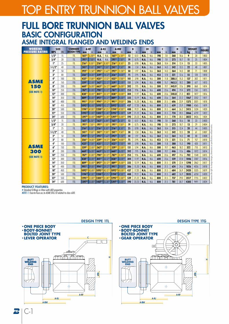
WORKINGPRESSURE RATING
SIZE STANDARDDESIGN TYPE
A-RF A-RJ A-BW B B1 C H WEIGHT FIGURENPS DN mm in mm in mm in mm in mm in mm in mm in kg lb
ASME150
(SEE NOTE 1)
1/2" 15 1TL 165(¹) 6.50(¹) N.A. N.A. 165(¹) 6.50(¹) 13 0.51 N.A. N.A. 198 7.8 268 10.6 9 20 1-B033/4" 20 1TL 191(¹) 7.50(¹) N.A. N.A. 191(¹) 7.50(¹) 19 0.75 N.A. N.A. 198 7.8 273 10.7 11 25 1-B041" 25 1TL 216(¹) 8.50(¹) 216(¹) 8.50(¹) 216(¹) 8.50(¹) 25 0.98 N.A. N.A. 263 10.4 314 12.4 15 33 1-B05
1-1/2" 40 1TL 241(¹) 9.50(¹) 241(¹) 9.50(¹) 241(¹) 9.50(¹) 38 1.50 N.A. N.A. 363 14.3 342 13.5 22 48 1-B072" 50 1TL 292(¹) 11.50(¹) 295(¹) 11.62(¹) 292(¹) 11.50(¹) 50 1.97 N.A. N.A. 363 14.3 364 14.3 32 71 1-B083" 80 1TL 356(¹) 14.00(¹) 359(¹) 14.12(¹) 356(¹) 14.00(¹) 75 2.95 N.A. N.A. 453 17.8 321 12.6 55 120 1-B104" 100 1TG 432(¹) 17.00(¹) 435(¹) 17.12(¹) 432(¹) 17.00(¹) 101 3.98 N.A. N.A. 300 11.8 388.5 15.3 137 302 1-B116" 150 1TG 559(¹) 22.00(¹) 562(¹) 22.12(¹) 559(¹) 22.00(¹) 151 5.94 N.A. N.A. 400 15.7 463.5 18.2 280 617 1-B138" 200 1TG 660(¹) 26.00(¹) 663(¹) 26.12(¹) 660(¹) 26.00(¹) 202 7.95 N.A. N.A. 500 19.7 445.9 17.6 390 860 1-B1410" 250 1TG 787(¹) 31.00(¹) 790(¹) 31.12(¹) 787(¹) 31.00(¹) 253 9.96 N.A. N.A. 600 23.6 494 19.4 572 1261 1-B1512" 300 1TG 838(¹) 33.00(¹) 841(¹) 33.12(¹) 838(¹) 33.00(¹) 304 11.97 N.A. N.A. 600 23.6 540.8 21.3 851 1877 1-B1614" 350 1TG 889(¹) 35.00(¹) 892(¹) 35.12(¹) 889(¹) 35.00(¹) 335 13.19 N.A. N.A. 600 23.6 564 22.2 1067 2352 1-B1716" 400 1TG 991(¹) 39.00(¹) 994(¹) 39.12(¹) 991(¹) 39.00(¹) 386 15.20 N.A. N.A. 800 31.5 606 23.9 1375 3031 1-B1818" 450 1TG 1092(¹) 43.00(¹) 1095(¹) 43.12(¹) 1092(¹) 43.00(¹) 437 17.20 N.A. N.A. 800 31.5 659 25.9 1980 4365 1-B1920" 500 1TG 1194(¹) 47.00(¹) 1200(¹) 47.25(¹) 1194(¹) 47.00(¹) 488 19.21 N.A. N.A. 800 31.5 664 26.2 2415 5324 1-B2022" 550 1TG 1295(¹) 51.00(¹) 1305(¹) 51.38(¹) 1295(¹) 51.00(¹) 539 21.22 N.A. N.A. 800 31.5 724 28.5 3066 6759 1-B2224" 600 1TG 1397(¹) 55.00(¹) 1407(¹) 55.38(¹) 1397(¹) 55.00(¹) 590 23.23 N.A. N.A. 800 31.5 770 30.3 3822 8426 1-B24
ASME300
(SEE NOTE 1)
1/2" 15 1TL 165(¹) 6.50(¹) 163(¹) 6.44(¹) 165(¹) 6.50(¹) 13 0.51 N.A. N.A. 198 7.8 268 10.6 10 23 3-B033/4" 20 1TL 191(¹) 7.50(¹) 191(¹) 7.50(¹) 191(¹) 7.50(¹) 19 0.75 N.A. N.A. 198 7.8 273 10.7 13 29 3-B041" 25 1TL 216(¹) 8.50(¹) 216(¹) 8.50(¹) 216(¹) 8.50(¹) 25 0.98 N.A. N.A. 263 10.4 315 12.4 20 44 3-B05
1-1/2" 40 1TL 241(¹) 9.50(¹) 241(¹) 9.50(¹) 241(¹) 9.50(¹) 38 1.50 N.A. N.A. 363 14.3 342 13.5 28 61 3-B072" 50 1TL 292(¹) 11.50(¹) 295(¹) 11.62(¹) 292(¹) 11.50(¹) 50 1.97 N.A. N.A. 363 14.3 364 14.3 40 88 3-B083" 80 1TL 356(¹) 14.00(¹) 359(¹) 14.12(¹) 356(¹) 14.00(¹) 75 2.95 N.A. N.A. 453 17.8 321 12.6 71 157 3-B104" 100 1TG 432(¹) 17.00(¹) 435(¹) 17.12(¹) 432(¹) 17.00(¹) 101 3.98 N.A. N.A. 300 11.8 388 15.3 190 420 3-B116" 150 1TG 559(¹) 22.00(¹) 562(¹) 22.12(¹) 559(¹) 22.00(¹) 151 5.94 N.A. N.A. 500 19.7 463 18.2 322 710 3-B138" 200 1TG 660(¹) 26.00(¹) 663(¹) 26.12(¹) 660(¹) 26.00(¹) 202 7.95 N.A. N.A. 500 19.7 446 17.6 486 1072 3-B1410" 250 1TG 787(¹) 31.00(¹) 790(¹) 31.12(¹) 787(¹) 31.00(¹) 253 9.96 N.A. N.A. 600 23.6 497 19.6 702 1548 3-B1512" 300 1TG 838(¹) 33.00(¹) 841(¹) 33.12(¹) 838(¹) 33.00(¹) 304 11.97 N.A. N.A. 600 23.6 559 22.0 1046 2307 3-B1614" 350 1TG 889(¹) 35.00(¹) 892(¹) 35.12(¹) 889(¹) 35.00(¹) 335 13.19 N.A. N.A. 800 31.5 570 22.4 1298 2862 3-B1716" 400 1TG 991(¹) 39.00(¹) 994(¹) 39.12(¹) 991(¹) 39.00(¹) 386 15.20 N.A. N.A. 800 31.5 624 24.6 1826 4026 3-B1818" 450 1TG 1092(¹) 43.00(¹) 1095(¹) 43.12(¹) 1092(¹) 43.00(¹) 437 17.20 N.A. N.A. 800 31.5 684 26.9 2420 5335 3-B1920" 500 1TG 1194(¹) 47.00(¹) 1200(¹) 47.25(¹) 1194(¹) 47.00(¹) 488 19.21 N.A. N.A. 800 31.5 682 26.9 2835 6250 3-B2022" 550 1TG 1295(¹) 51.00(¹) 1305(¹) 51.38(¹) 1295(¹) 51.00(¹) 539 21.22 N.A. N.A. 800 31.5 737 29.0 3517 7755 3-B2224" 600 1TG 1397(¹) 55.00(¹) 1407(¹) 55.38(¹) 1397(¹) 55.00(¹) 590 23.23 N.A. N.A. 800 31.5 781 30.7 4305 9491 3-B24
TOP ENTRY TRUNNION BALL VALVES
PRODUCT FEATURES:• Standard O-Rings in Viton with AED properties. NOTE 1: Face-to-Face acc.to ASME B16.10 related to class 600.
BFE r
eser
ves t
he ri
ght t
o cha
nge d
esign
s, dim
ensio
ns or
spec
ifica
tions
with
out n
otice
.
FULL BORE TRUNNION BALL VALVES BASIC CONFIGURATIONASME INTEGRAL FLANGED AND WELDING ENDS
A-RJ
BUTT WELDING
END
H
A-RF
A-BW
• ONE PIECE BODY• BODY-BONNET BOLTED JOINT TYPE
• GEAR OPERATOR
DESIGN TYPE 1TG
ØB
ØC
BUTT WELDING
END
A-RJ
C
BUTT WELDING
END
H
A-RF
A-BW
• ONE PIECE BODY• BODY-BONNET BOLTED JOINT TYPE
• LEVER OPERATOR
DESIGN TYPE 1TL
ØB
C-1
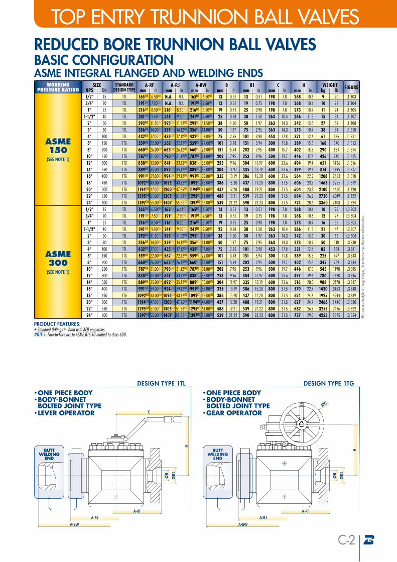
WORKINGPRESSURE RATING
SIZE STANDARDDESIGN TYPE
A-RF A-RJ A-BW B B1 C H WEIGHT FIGURENPS DN mm in mm in mm in mm in mm in mm in mm in kg lb
ASME150
(SEE NOTE 1)
1/2" 15 1TL 165(¹) 6.50(¹) N.A. N.A. 165(¹) 6.50(¹) 13 0.51 13 0.51 198 7.8 268 10.6 9 20 L1 B033/4" 20 1TL 191(¹) 7.50(¹) N.A. N.A. 191(¹) 7.50(¹) 13 0.51 19 0.75 198 7.8 268 10.6 10 22 L1 B041" 25 1TL 216(¹) 8.50(¹) 216(¹) 8.50(¹) 216(¹) 8.50(¹) 19 0.75 25 0.98 198 7.8 273 10.7 11 24 L1 B05
1-1/2" 40 1TL 241(¹) 9.50(¹) 241(¹) 9.50(¹) 241(¹) 9.50(¹) 25 0.98 38 1.50 263 10.4 286 11.3 15 34 L1 B072" 50 1TL 292(¹) 11.50(¹) 295(¹) 11.62(¹) 292(¹) 11.50(¹) 38 1.50 50 1.97 363 14.3 342 13.5 27 59 L1 B083" 80 1TL 356(¹) 14.00(¹) 359(¹) 14.12(¹) 356(¹) 14.00(¹) 50 1.97 75 2.95 363 14.3 273 10.7 38 84 L1 B104" 100 1TL 432(¹) 17.00(¹) 435(¹) 17.12(¹) 432(¹) 17.00(¹) 75 2.95 101 3.98 453 17.8 321 12.6 61 135 L1 B116" 150 1TG 559(¹) 22.00(¹) 562(¹) 22.12(¹) 559(¹) 22.00(¹) 101 3.98 151 5.94 300 11.8 389 15.3 168 370 L1 B138" 200 1TG 660(¹) 26.00(¹) 663(¹) 26.12(¹) 660(¹) 26.00(¹) 151 5.94 202 7.95 400 15.7 402 15.8 290 639 L1 B1410" 250 1TG 787(¹) 31.00(¹) 790(¹) 31.12(¹) 787(¹) 31.00(¹) 202 7.95 253 9.96 500 19.7 446 17.6 426 940 L1 B1512" 300 1TG 838(¹) 33.00(¹) 841(¹) 33.12(¹) 838(¹) 33.00(¹) 253 9.96 304 11.97 600 23.6 494 19.4 651 1436 L1 B1614" 350 1TG 889(¹) 35.00(¹) 892(¹) 35.12(¹) 889(¹) 35.00(¹) 304 11.97 335 13.19 600 23.6 499 19.7 814 1795 L1 B1716" 400 1TG 991(¹) 39.00(¹) 994(¹) 39.12(¹) 991(¹) 39.00(¹) 335 13.19 386 15.20 600 23.6 564 22.2 1208 2663 L1 B1818" 450 1TG 1092(¹) 43.00(¹) 1095(¹) 43.12(¹) 1092(¹) 43.00(¹) 386 15.20 437 17.20 800 31.5 606 23.9 1463 3225 L1 B1920" 500 1TG 1194(¹) 47.00(¹) 1200(¹) 47.25(¹) 1194(¹) 47.00(¹) 437 17.20 488 19.21 800 31.5 604 23.8 2100 4630 L1 B2022" 550 1TG 1295(¹) 51.00(¹) 1305(¹) 51.38(¹) 1295(¹) 51.00(¹) 488 19.21 539 21.22 800 31.5 664 26.2 2730 6019 L1 B2224" 600 1TG 1397(¹) 55.00(¹) 1407(¹) 55.38(¹) 1397(¹) 55.00(¹) 539 21.22 590 23.23 800 31.5 724 28.5 3360 7408 L1 B24
ASME300
(SEE NOTE 1)
1/2" 15 1TL 165(¹) 6.50(¹) 163(¹) 6.44(¹) 165(¹) 6.50(¹) 13 0.51 13 0.51 198 7.8 268 10.6 10 23 L3 B033/4" 20 1TL 191(¹) 7.50(¹) 191(¹) 7.50(¹) 191(¹) 7.50(¹) 13 0.51 19 0.75 198 7.8 268 10.6 12 27 L3 B041" 25 1TL 216(¹) 8.50(¹) 216(¹) 8.50(¹) 216(¹) 8.50(¹) 19 0.75 25 0.98 198 7.8 273 10.7 16 35 L3 B05
1-1/2" 40 1TL 241(¹) 9.50(¹) 241(¹) 9.50(¹) 241(¹) 9.50(¹) 25 0.98 38 1.50 263 10.4 286 11.3 21 47 L3 B072" 50 1TL 292(¹) 11.50(¹) 295(¹) 11.62(¹) 292(¹) 11.50(¹) 38 1.50 50 1.97 363 14.3 342 13.5 30 66 L3 B083" 80 1TL 356(¹) 14.00(¹) 359(¹) 14.12(¹) 356(¹) 14.00(¹) 50 1.97 75 2.95 363 14.3 273 10.7 50 110 L3 B104" 100 1TL 432(¹) 17.00(¹) 435(¹) 17.12(¹) 432(¹) 17.00(¹) 75 2.95 101 3.98 453 17.8 321 12.6 83 184 L3 B116" 150 1TG 559(¹) 22.00(¹) 562(¹) 22.12(¹) 559(¹) 22.00(¹) 101 3.98 151 5.94 300 11.8 389 15.3 225 497 L3 B138" 200 1TG 660(¹) 26.00(¹) 663(¹) 26.12(¹) 660(¹) 26.00(¹) 151 5.94 202 7.95 500 19.7 402 15.8 345 759 L3 B1410" 250 1TG 787(¹) 31.00(¹) 790(¹) 31.12(¹) 787(¹) 31.00(¹) 202 7.95 253 9.96 500 19.7 446 17.6 543 1198 L3 B1512" 300 1TG 838(¹) 33.00(¹) 841(¹) 33.12(¹) 838(¹) 33.00(¹) 253 9.96 304 11.97 600 23.6 497 19.6 780 1720 L3 B1614" 350 1TG 889(¹) 35.00(¹) 892(¹) 35.12(¹) 889(¹) 35.00(¹) 304 11.97 335 13.19 600 23.6 516 20.3 988 2178 L3 B1716" 400 1TG 991(¹) 39.00(¹) 994(¹) 39.12(¹) 991(¹) 39.00(¹) 335 13.19 386 15.20 800 31.5 570 22.4 1430 3153 L3 B1818" 450 1TG 1092(¹) 43.00(¹) 1095(¹) 43.12(¹) 1092(¹) 43.00(¹) 386 15.20 437 17.20 800 31.5 624 24.6 1925 4244 L3 B1920" 500 1TG 1194(¹) 47.00(¹) 1200(¹) 47.25(¹) 1194(¹) 47.00(¹) 437 17.20 488 19.21 800 31.5 627 24.7 2468 5440 L3 B2022" 550 1TG 1295(¹) 51.00(¹) 1305(¹) 51.38(¹) 1295(¹) 51.00(¹) 488 19.21 539 21.22 800 31.5 682 26.9 3255 7176 L3 B2224" 600 1TG 1397(¹) 55.00(¹) 1407(¹) 55.38(¹) 1397(¹) 55.00(¹) 539 21.22 590 23.23 800 31.5 737 29.0 4253 9375 L3 B24
TOP ENTRY TRUNNION BALL VALVES
PRODUCT FEATURES:• Standard O-Rings in Viton with AED properties. NOTE 1: Face-to-Face acc.to ASME B16.10 related to class 600.
BFE r
eser
ves t
he ri
ght t
o cha
nge d
esign
s, dim
ensio
ns or
spec
ifica
tions
with
out n
otice
.
REDUCED BORE TRUNNION BALL VALVES BASIC CONFIGURATIONASME INTEGRAL FLANGED AND WELDING ENDS
C-2
A-RJ
BUTT WELDING
END
H
A-RF
A-BW
• ONE PIECE BODY• BODY-BONNET BOLTED JOINT TYPE
• GEAR OPERATOR
DESIGN TYPE 1TG
ØB
ØC
ØB1
BUTT WELDING
END
A-RJ
C
BUTT WELDING
END
H
A-RF
A-BW
• ONE PIECE BODY• BODY-BONNET BOLTED JOINT TYPE
• LEVER OPERATOR
DESIGN TYPE 1TL
ØB
ØB1

SIDE ENTRY TRUNNION BALL VALVESTOP ENTRY TRUNNION BALL VALVES
C-3
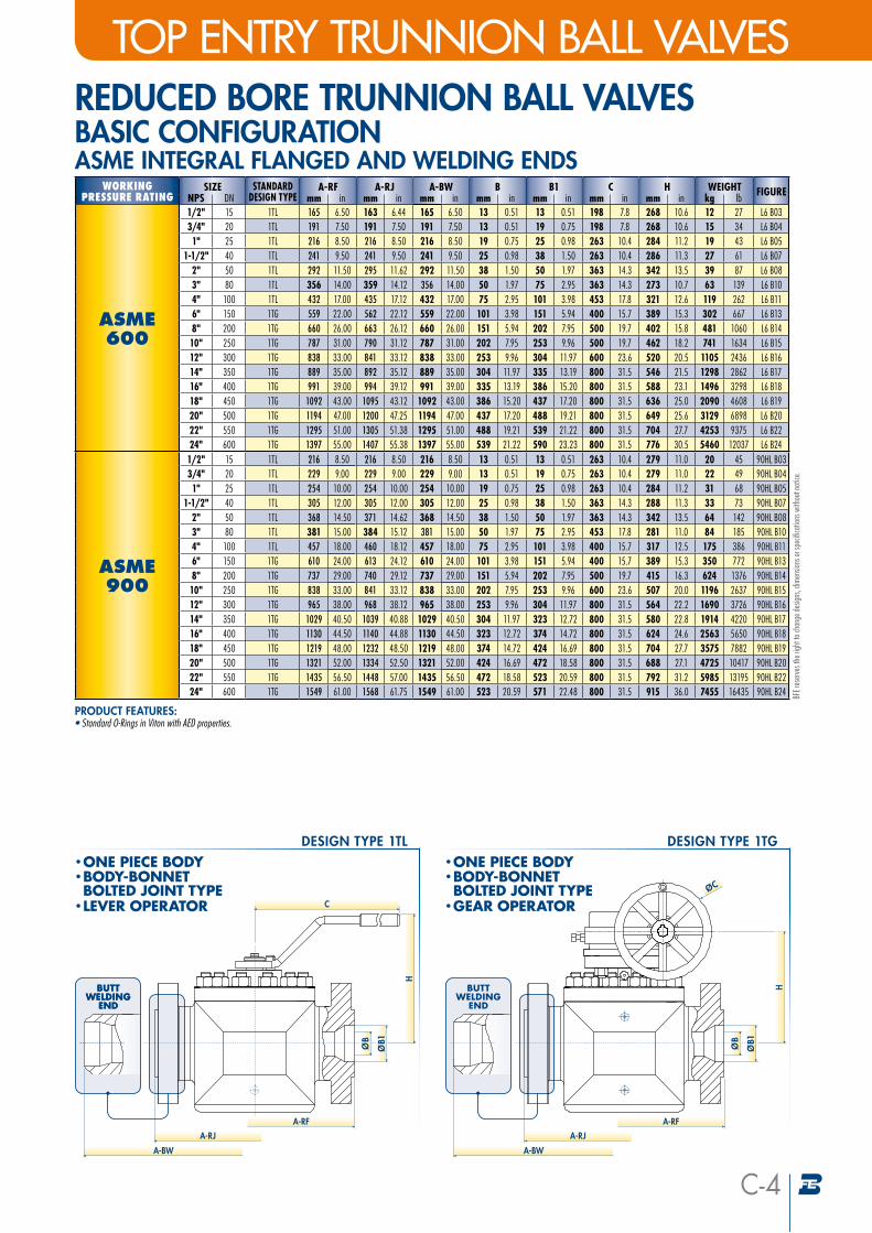
WORKINGPRESSURE RATING
SIZE STANDARDDESIGN TYPE
A-RF A-RJ A-BW B B1 C H WEIGHT FIGURENPS DN mm in mm in mm in mm in mm in mm in mm in kg lb
ASME600
1/2" 15 1TL 165 6.50 163 6.44 165 6.50 13 0.51 N.A. N.A. 198 7.8 268 10.6 12 27 6-B033/4" 20 1TL 191 7.50 191 7.50 191 7.50 19 0.75 N.A. N.A. 263 10.4 284 11.2 17 38 6-B041" 25 1TL 216 8.50 216 8.50 216 8.50 25 0.98 N.A. N.A. 263 10.4 315 12.4 25 54 6-B05
1-1/2" 40 1TL 241 9.50 241 9.50 241 9.50 38 1.50 N.A. N.A. 363 14.3 342 13.5 34 75 6-B072" 50 1TL 292 11.50 295 11.62 292 11.50 50 1.97 N.A. N.A. 363 14.3 364 14.3 52 115 6-B083" 80 1TL 356 14.00 359 14.12 356 14.00 75 2.95 N.A. N.A. 453 17.8 321 12.6 91 200 6-B104" 100 1TG 432 17.00 435 17.12 432 17.00 101 3.98 N.A. N.A. 400 15.7 389 15.3 242 534 6-B116" 150 1TG 559 22.00 562 22.12 559 22.00 151 5.94 N.A. N.A. 500 19.7 464 18.2 442 975 6-B138" 200 1TG 660 26.00 663 26.12 660 26.00 202 7.95 N.A. N.A. 500 19.7 462 18.2 680 1499 6-B1410" 250 1TG 787 31.00 790 31.12 787 31.00 253 9.96 N.A. N.A. 600 23.6 520 20.5 1040 2293 6-B1512" 300 1TG 838 33.00 841 33.12 838 33.00 304 11.97 N.A. N.A. 800 31.5 592 23.3 1430 3153 6-B1614" 350 1TG 889 35.00 892 35.12 889 35.00 335 13.19 N.A. N.A. 800 31.5 588 23.1 1375 3031 6-B1716" 400 1TG 991 39.00 994 39.12 991 39.00 386 15.20 N.A. N.A. 800 31.5 636 25.0 1925 4244 6-B1818" 450 1TG 1092 43.00 1095 43.12 1092 43.00 437 17.20 N.A. N.A. 800 31.5 708 27.9 2915 6426 6-B1920" 500 1TG 1194 47.00 1200 47.25 1194 47.00 488 19.21 N.A. N.A. 800 31.5 704 27.7 3308 7292 6-B2022" 550 1TG 1295 51.00 1305 51.38 1295 51.00 539 21.22 N.A. N.A. 800 31.5 776 30.5 4515 9954 6-B2224" 600 1TG 1397 55.00 1407 55.38 1397 55.00 590 23.23 N.A. N.A. 800 31.5 825 32.5 5565 12269 6-B24
ASME900
1/2" 15 1TL 216 8.50 216 8.50 216 8.50 13 0.51 N.A. N.A. 263 10.4 279 11.0 20 45 90H B033/4" 20 1TL 229 9.00 229 9.00 229 9.00 19 0.75 N.A. N.A. 263 10.4 284 11.2 24 52 90H B041" 25 1TL 254 10.00 254 10.00 254 10.00 25 0.98 N.A. N.A. 363 14.3 317 12.5 35 78 90H B05
1-1/2" 40 1TL 305 12.00 305 12.00 305 12.00 38 1.50 N.A. N.A. 363 14.3 342 13.5 48 105 90H B072" 50 1TL 368 14.50 371 14.62 368 14.50 50 1.97 N.A. N.A. 453 17.8 374 14.7 80 177 90H B083" 80 1TG 381 15.00 384 15.12 381 15.00 75 2.95 N.A. N.A. 400 15.7 317 12.5 146 321 90H B104" 100 1TG 457 18.00 460 18.12 457 18.00 101 3.98 N.A. N.A. 400 15.7 389 15.3 262 577 90H B116" 150 1TG 610 24.00 613 24.12 610 24.00 151 5.94 N.A. N.A. 500 19.7 479 18.8 567 1250 90H B138" 200 1TG 737 29.00 740 29.12 737 29.00 202 7.95 N.A. N.A. 600 23.6 507 20.0 1053 2321 90H B1410" 250 1TG 838 33.00 841 33.12 838 33.00 253 9.96 N.A. N.A. 800 31.5 564 22.2 1508 3325 90H B1512" 300 1TG 965 38.00 968 38.12 965 38.00 304 11.97 N.A. N.A. 800 31.5 628 24.7 2132 4700 90H B1614" 350 1TG 1029 40.50 1039 40.88 1029 40.50 323 12.72 N.A. N.A. 800 31.5 624 24.6 2365 5214 90H B1716" 400 1TG 1130 44.50 1140 44.88 1130 44.50 374 14.72 N.A. N.A. 800 31.5 704 27.7 3333 7348 90H B1818" 450 1TG 1219 48.00 1232 48.50 1219 48.00 424 16.69 N.A. N.A. 800 31.5 750 29.5 3740 8245 90H B1920" 500 1TG 1321 52.00 1334 52.50 1321 52.00 472 18.58 N.A. N.A. 800 31.5 792 31.2 5093 11227 90H B2022" 550 1TG 1435 56.50 1448 57.00 1435 56.50 523 20.59 N.A. N.A. 800 31.5 915 36.0 6195 13658 90H B2224" 600 1TG 1549 61.00 1568 61.75 1549 61.00 571 22.48 N.A. N.A. 800 31.5 935 36.8 7823 17246 90H B24
PRODUCT FEATURES:• Standard O-Rings in Viton with AED properties.
BFE r
eser
ves t
he ri
ght t
o cha
nge d
esign
s, dim
ensio
ns or
spec
ifica
tions
with
out n
otice
.
FULL BORE TRUNNION BALL VALVES BASIC CONFIGURATIONASME INTEGRAL FLANGED AND WELDING ENDS
A-RJ
BUTT WELDING
END
H
A-RF
A-BW
• ONE PIECE BODY• BODY-BONNET BOLTED JOINT TYPE
• GEAR OPERATOR
DESIGN TYPE 1TG
ØB
ØC
BUTT WELDING
END
A-RJ
C
BUTT WELDING
END
H
A-RF
A-BW
• ONE PIECE BODY• BODY-BONNET BOLTED JOINT TYPE
• LEVER OPERATOR
DESIGN TYPE 1TL
ØB
SIDE ENTRY TRUNNION BALL VALVESTOP ENTRY TRUNNION BALL VALVES
C-4
WORKINGPRESSURE RATING
SIZE STANDARDDESIGN TYPE
A-RF A-RJ A-BW B B1 C H WEIGHT FIGURENPS DN mm in mm in mm in mm in mm in mm in mm in kg lb
ASME600
1/2" 15 1TL 165 6.50 163 6.44 165 6.50 13 0.51 13 0.51 198 7.8 268 10.6 12 27 L6 B033/4" 20 1TL 191 7.50 191 7.50 191 7.50 13 0.51 19 0.75 198 7.8 268 10.6 15 34 L6 B041" 25 1TL 216 8.50 216 8.50 216 8.50 19 0.75 25 0.98 263 10.4 284 11.2 19 43 L6 B05
1-1/2" 40 1TL 241 9.50 241 9.50 241 9.50 25 0.98 38 1.50 263 10.4 286 11.3 27 61 L6 B072" 50 1TL 292 11.50 295 11.62 292 11.50 38 1.50 50 1.97 363 14.3 342 13.5 39 87 L6 B083" 80 1TL 356 14.00 359 14.12 356 14.00 50 1.97 75 2.95 363 14.3 273 10.7 63 139 L6 B104" 100 1TL 432 17.00 435 17.12 432 17.00 75 2.95 101 3.98 453 17.8 321 12.6 119 262 L6 B116" 150 1TG 559 22.00 562 22.12 559 22.00 101 3.98 151 5.94 400 15.7 389 15.3 302 667 L6 B138" 200 1TG 660 26.00 663 26.12 660 26.00 151 5.94 202 7.95 500 19.7 402 15.8 481 1060 L6 B1410" 250 1TG 787 31.00 790 31.12 787 31.00 202 7.95 253 9.96 500 19.7 462 18.2 741 1634 L6 B1512" 300 1TG 838 33.00 841 33.12 838 33.00 253 9.96 304 11.97 600 23.6 520 20.5 1105 2436 L6 B1614" 350 1TG 889 35.00 892 35.12 889 35.00 304 11.97 335 13.19 800 31.5 546 21.5 1298 2862 L6 B1716" 400 1TG 991 39.00 994 39.12 991 39.00 335 13.19 386 15.20 800 31.5 588 23.1 1496 3298 L6 B1818" 450 1TG 1092 43.00 1095 43.12 1092 43.00 386 15.20 437 17.20 800 31.5 636 25.0 2090 4608 L6 B1920" 500 1TG 1194 47.00 1200 47.25 1194 47.00 437 17.20 488 19.21 800 31.5 649 25.6 3129 6898 L6 B2022" 550 1TG 1295 51.00 1305 51.38 1295 51.00 488 19.21 539 21.22 800 31.5 704 27.7 4253 9375 L6 B2224" 600 1TG 1397 55.00 1407 55.38 1397 55.00 539 21.22 590 23.23 800 31.5 776 30.5 5460 12037 L6 B24
ASME900
1/2" 15 1TL 216 8.50 216 8.50 216 8.50 13 0.51 13 0.51 263 10.4 279 11.0 20 45 90HL B033/4" 20 1TL 229 9.00 229 9.00 229 9.00 13 0.51 19 0.75 263 10.4 279 11.0 22 49 90HL B041" 25 1TL 254 10.00 254 10.00 254 10.00 19 0.75 25 0.98 263 10.4 284 11.2 31 68 90HL B05
1-1/2" 40 1TL 305 12.00 305 12.00 305 12.00 25 0.98 38 1.50 363 14.3 288 11.3 33 73 90HL B072" 50 1TL 368 14.50 371 14.62 368 14.50 38 1.50 50 1.97 363 14.3 342 13.5 64 142 90HL B083" 80 1TL 381 15.00 384 15.12 381 15.00 50 1.97 75 2.95 453 17.8 281 11.0 84 185 90HL B104" 100 1TL 457 18.00 460 18.12 457 18.00 75 2.95 101 3.98 400 15.7 317 12.5 175 386 90HL B116" 150 1TG 610 24.00 613 24.12 610 24.00 101 3.98 151 5.94 400 15.7 389 15.3 350 772 90HL B138" 200 1TG 737 29.00 740 29.12 737 29.00 151 5.94 202 7.95 500 19.7 415 16.3 624 1376 90HL B1410" 250 1TG 838 33.00 841 33.12 838 33.00 202 7.95 253 9.96 600 23.6 507 20.0 1196 2637 90HL B1512" 300 1TG 965 38.00 968 38.12 965 38.00 253 9.96 304 11.97 800 31.5 564 22.2 1690 3726 90HL B1614" 350 1TG 1029 40.50 1039 40.88 1029 40.50 304 11.97 323 12.72 800 31.5 580 22.8 1914 4220 90HL B1716" 400 1TG 1130 44.50 1140 44.88 1130 44.50 323 12.72 374 14.72 800 31.5 624 24.6 2563 5650 90HL B1818" 450 1TG 1219 48.00 1232 48.50 1219 48.00 374 14.72 424 16.69 800 31.5 704 27.7 3575 7882 90HL B1920" 500 1TG 1321 52.00 1334 52.50 1321 52.00 424 16.69 472 18.58 800 31.5 688 27.1 4725 10417 90HL B2022" 550 1TG 1435 56.50 1448 57.00 1435 56.50 472 18.58 523 20.59 800 31.5 792 31.2 5985 13195 90HL B2224" 600 1TG 1549 61.00 1568 61.75 1549 61.00 523 20.59 571 22.48 800 31.5 915 36.0 7455 16435 90HL B24
PRODUCT FEATURES:• Standard O-Rings in Viton with AED properties.
BFE r
eser
ves t
he ri
ght t
o cha
nge d
esign
s, dim
ensio
ns or
spec
ifica
tions
with
out n
otice
.
REDUCED BORE TRUNNION BALL VALVES BASIC CONFIGURATIONASME INTEGRAL FLANGED AND WELDING ENDS
A-RJ
BUTT WELDING
END
H
A-RF
A-BW
• ONE PIECE BODY• BODY-BONNET BOLTED JOINT TYPE
• GEAR OPERATOR
DESIGN TYPE 1TG
ØB
ØC
ØB1
BUTT WELDING
END
A-RJ
C
BUTT WELDING
END
H
A-RF
A-BW
• ONE PIECE BODY• BODY-BONNET BOLTED JOINT TYPE
• LEVER OPERATOR
DESIGN TYPE 1TL
ØB
ØB1
SIDE ENTRY TRUNNION BALL VALVESTOP ENTRY TRUNNION BALL VALVES
C-5
WORKINGPRESSURE RATING
SIZE STANDARDDESIGN TYPE
A-RF A-RJ A-BW B B1 C H WEIGHT FIGURENPS DN mm in mm in mm in mm in mm in mm in mm in kg lb
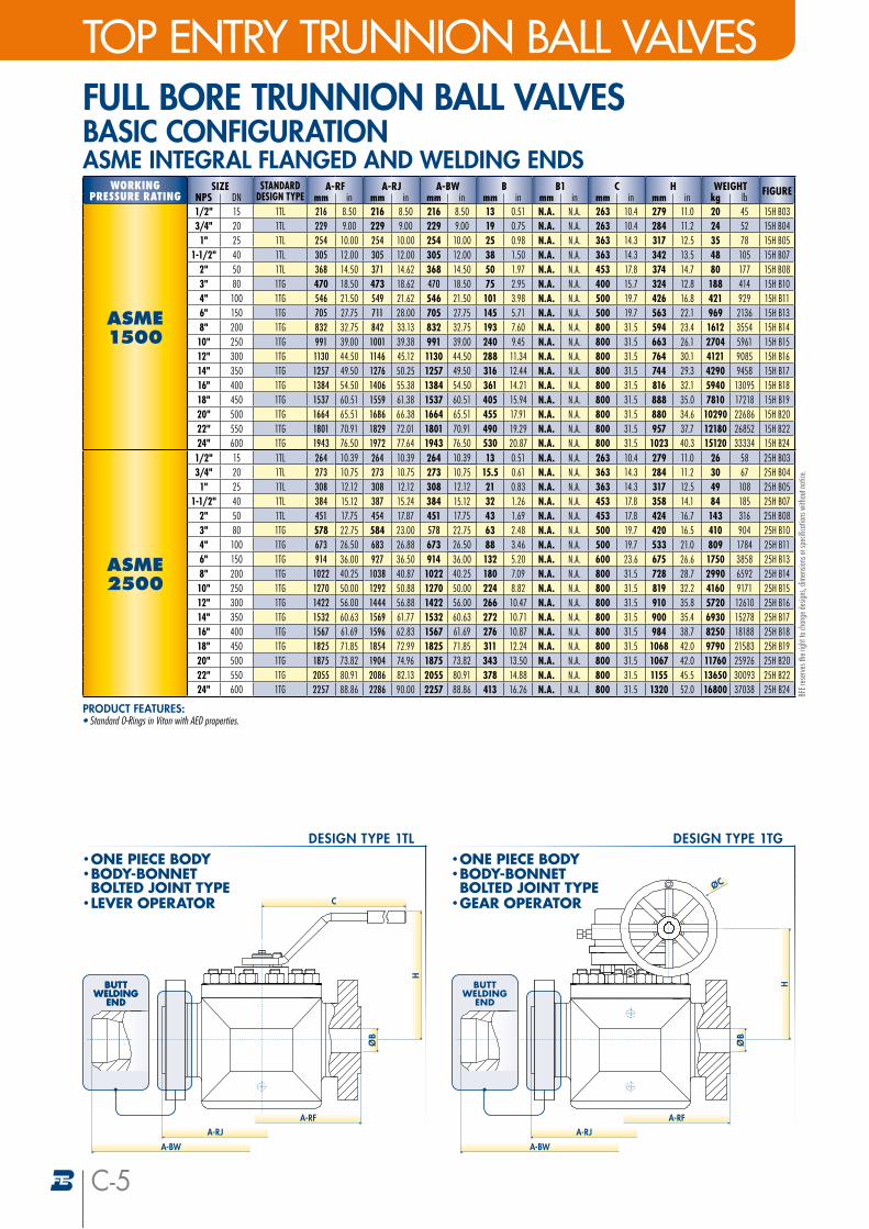
ASME1500
1/2" 15 1TL 216 8.50 216 8.50 216 8.50 13 0.51 N.A. N.A. 263 10.4 279 11.0 20 45 15H B033/4" 20 1TL 229 9.00 229 9.00 229 9.00 19 0.75 N.A. N.A. 263 10.4 284 11.2 24 52 15H B041" 25 1TL 254 10.00 254 10.00 254 10.00 25 0.98 N.A. N.A. 363 14.3 317 12.5 35 78 15H B05
1-1/2" 40 1TL 305 12.00 305 12.00 305 12.00 38 1.50 N.A. N.A. 363 14.3 342 13.5 48 105 15H B072" 50 1TL 368 14.50 371 14.62 368 14.50 50 1.97 N.A. N.A. 453 17.8 374 14.7 80 177 15H B083" 80 1TG 470 18.50 473 18.62 470 18.50 75 2.95 N.A. N.A. 400 15.7 324 12.8 188 414 15H B104" 100 1TG 546 21.50 549 21.62 546 21.50 101 3.98 N.A. N.A. 500 19.7 426 16.8 421 929 15H B116" 150 1TG 705 27.75 711 28.00 705 27.75 145 5.71 N.A. N.A. 500 19.7 563 22.1 969 2136 15H B138" 200 1TG 832 32.75 842 33.13 832 32.75 193 7.60 N.A. N.A. 800 31.5 594 23.4 1612 3554 15H B1410" 250 1TG 991 39.00 1001 39.38 991 39.00 240 9.45 N.A. N.A. 800 31.5 663 26.1 2704 5961 15H B1512" 300 1TG 1130 44.50 1146 45.12 1130 44.50 288 11.34 N.A. N.A. 800 31.5 764 30.1 4121 9085 15H B1614" 350 1TG 1257 49.50 1276 50.25 1257 49.50 316 12.44 N.A. N.A. 800 31.5 744 29.3 4290 9458 15H B1716" 400 1TG 1384 54.50 1406 55.38 1384 54.50 361 14.21 N.A. N.A. 800 31.5 816 32.1 5940 13095 15H B1818" 450 1TG 1537 60.51 1559 61.38 1537 60.51 405 15.94 N.A. N.A. 800 31.5 888 35.0 7810 17218 15H B1920" 500 1TG 1664 65.51 1686 66.38 1664 65.51 455 17.91 N.A. N.A. 800 31.5 880 34.6 10290 22686 15H B2022" 550 1TG 1801 70.91 1829 72.01 1801 70.91 490 19.29 N.A. N.A. 800 31.5 957 37.7 12180 26852 15H B2224" 600 1TG 1943 76.50 1972 77.64 1943 76.50 530 20.87 N.A. N.A. 800 31.5 1023 40.3 15120 33334 15H B24
ASME2500
1/2" 15 1TL 264 10.39 264 10.39 264 10.39 13 0.51 N.A. N.A. 263 10.4 279 11.0 26 58 25H B033/4" 20 1TL 273 10.75 273 10.75 273 10.75 15.5 0.61 N.A. N.A. 363 14.3 284 11.2 30 67 25H B041" 25 1TL 308 12.12 308 12.12 308 12.12 21 0.83 N.A. N.A. 363 14.3 317 12.5 49 108 25H B05
1-1/2" 40 1TL 384 15.12 387 15.24 384 15.12 32 1.26 N.A. N.A. 453 17.8 358 14.1 84 185 25H B072" 50 1TL 451 17.75 454 17.87 451 17.75 43 1.69 N.A. N.A. 453 17.8 424 16.7 143 316 25H B083" 80 1TG 578 22.75 584 23.00 578 22.75 63 2.48 N.A. N.A. 500 19.7 420 16.5 410 904 25H B104" 100 1TG 673 26.50 683 26.88 673 26.50 88 3.46 N.A. N.A. 500 19.7 533 21.0 809 1784 25H B116" 150 1TG 914 36.00 927 36.50 914 36.00 132 5.20 N.A. N.A. 600 23.6 675 26.6 1750 3858 25H B138" 200 1TG 1022 40.25 1038 40.87 1022 40.25 180 7.09 N.A. N.A. 800 31.5 728 28.7 2990 6592 25H B1410" 250 1TG 1270 50.00 1292 50.88 1270 50.00 224 8.82 N.A. N.A. 800 31.5 819 32.2 4160 9171 25H B1512" 300 1TG 1422 56.00 1444 56.88 1422 56.00 266 10.47 N.A. N.A. 800 31.5 910 35.8 5720 12610 25H B1614" 350 1TG 1532 60.63 1569 61.77 1532 60.63 272 10.71 N.A. N.A. 800 31.5 900 35.4 6930 15278 25H B1716" 400 1TG 1567 61.69 1596 62.83 1567 61.69 276 10.87 N.A. N.A. 800 31.5 984 38.7 8250 18188 25H B1818" 450 1TG 1825 71.85 1854 72.99 1825 71.85 311 12.24 N.A. N.A. 800 31.5 1068 42.0 9790 21583 25H B1920" 500 1TG 1875 73.82 1904 74.96 1875 73.82 343 13.50 N.A. N.A. 800 31.5 1067 42.0 11760 25926 25H B2022" 550 1TG 2055 80.91 2086 82.13 2055 80.91 378 14.88 N.A. N.A. 800 31.5 1155 45.5 13650 30093 25H B2224" 600 1TG 2257 88.86 2286 90.00 2257 88.86 413 16.26 N.A. N.A. 800 31.5 1320 52.0 16800 37038 25H B24
PRODUCT FEATURES:• Standard O-Rings in Viton with AED properties.
BFE r
eser
ves t
he ri
ght t
o cha
nge d
esign
s, dim
ensio
ns or
spec
ifica
tions
with
out n
otice
.
FULL BORE TRUNNION BALL VALVES BASIC CONFIGURATIONASME INTEGRAL FLANGED AND WELDING ENDS
A-RJ
BUTT WELDING
END
H
A-RF
A-BW
• ONE PIECE BODY• BODY-BONNET BOLTED JOINT TYPE
• GEAR OPERATOR
DESIGN TYPE 1TG
ØB
ØC
BUTT WELDING
END
A-RJ
C
BUTT WELDING
END
H
A-RF
A-BW
• ONE PIECE BODY• BODY-BONNET BOLTED JOINT TYPE
• LEVER OPERATOR
DESIGN TYPE 1TL
ØB
SIDE ENTRY TRUNNION BALL VALVESTOP ENTRY TRUNNION BALL VALVES
C-6
WORKINGPRESSURE RATING
SIZE STANDARDDESIGN TYPE
A-RF A-RJ A-BW B B1 C H WEIGHT FIGURENPS DN mm in mm in mm in mm in mm in mm in mm in kg lb
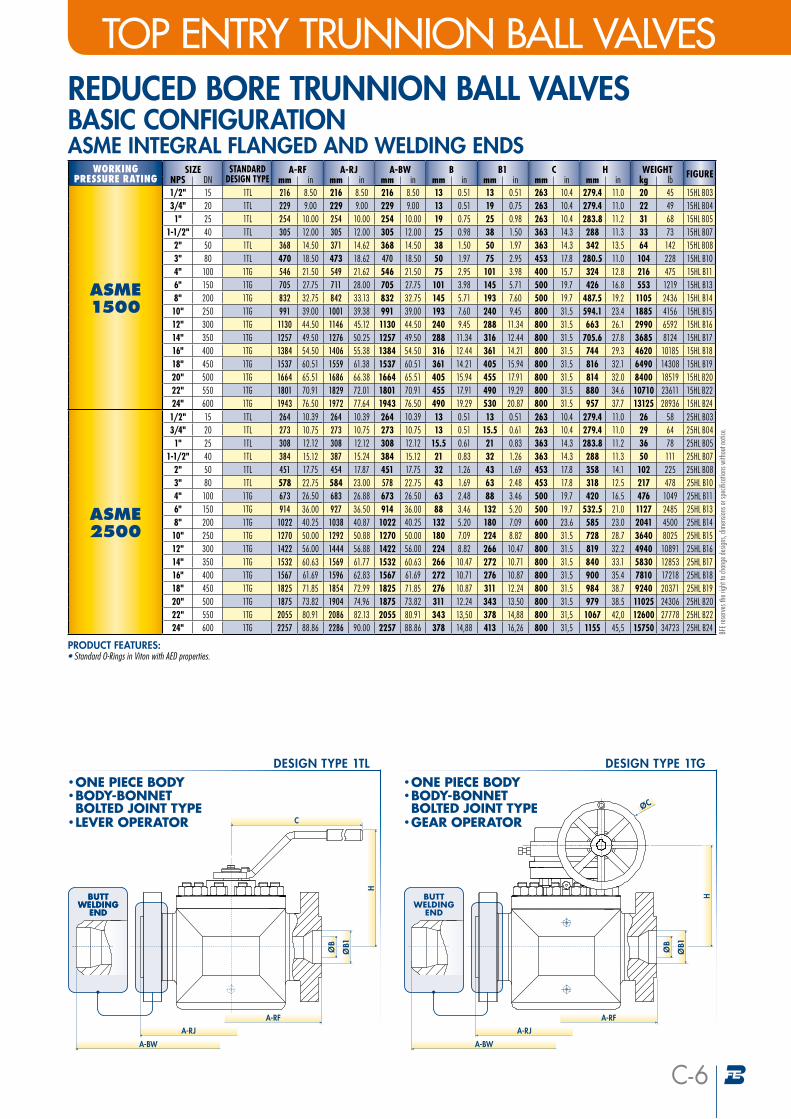
ASME1500
1/2" 15 1TL 216 8.50 216 8.50 216 8.50 13 0.51 13 0.51 263 10.4 279.4 11.0 20 45 15HL B033/4" 20 1TL 229 9.00 229 9.00 229 9.00 13 0.51 19 0.75 263 10.4 279.4 11.0 22 49 15HL B041" 25 1TL 254 10.00 254 10.00 254 10.00 19 0.75 25 0.98 263 10.4 283.8 11.2 31 68 15HL B05
1-1/2" 40 1TL 305 12.00 305 12.00 305 12.00 25 0.98 38 1.50 363 14.3 288 11.3 33 73 15HL B072" 50 1TL 368 14.50 371 14.62 368 14.50 38 1.50 50 1.97 363 14.3 342 13.5 64 142 15HL B083" 80 1TL 470 18.50 473 18.62 470 18.50 50 1.97 75 2.95 453 17.8 280.5 11.0 104 228 15HL B104" 100 1TG 546 21.50 549 21.62 546 21.50 75 2.95 101 3.98 400 15.7 324 12.8 216 475 15HL B116" 150 1TG 705 27.75 711 28.00 705 27.75 101 3.98 145 5.71 500 19.7 426 16.8 553 1219 15HL B138" 200 1TG 832 32.75 842 33.13 832 32.75 145 5.71 193 7.60 500 19.7 487.5 19.2 1105 2436 15HL B1410" 250 1TG 991 39.00 1001 39.38 991 39.00 193 7.60 240 9.45 800 31.5 594.1 23.4 1885 4156 15HL B1512" 300 1TG 1130 44.50 1146 45.12 1130 44.50 240 9.45 288 11.34 800 31.5 663 26.1 2990 6592 15HL B1614" 350 1TG 1257 49.50 1276 50.25 1257 49.50 288 11.34 316 12.44 800 31.5 705.6 27.8 3685 8124 15HL B1716" 400 1TG 1384 54.50 1406 55.38 1384 54.50 316 12.44 361 14.21 800 31.5 744 29.3 4620 10185 15HL B1818" 450 1TG 1537 60.51 1559 61.38 1537 60.51 361 14.21 405 15.94 800 31.5 816 32.1 6490 14308 15HL B1920" 500 1TG 1664 65.51 1686 66.38 1664 65.51 405 15.94 455 17.91 800 31.5 814 32.0 8400 18519 15HL B2022" 550 1TG 1801 70.91 1829 72.01 1801 70.91 455 17.91 490 19.29 800 31.5 880 34.6 10710 23611 15HL B2224" 600 1TG 1943 76.50 1972 77.64 1943 76.50 490 19.29 530 20.87 800 31.5 957 37.7 13125 28936 15HL B24
ASME2500
1/2" 15 1TL 264 10.39 264 10.39 264 10.39 13 0.51 13 0.51 263 10.4 279.4 11.0 26 58 25HL B033/4" 20 1TL 273 10.75 273 10.75 273 10.75 13 0.51 15.5 0.61 263 10.4 279.4 11.0 29 64 25HL B041" 25 1TL 308 12.12 308 12.12 308 12.12 15.5 0.61 21 0.83 363 14.3 283.8 11.2 36 78 25HL B05
1-1/2" 40 1TL 384 15.12 387 15.24 384 15.12 21 0.83 32 1.26 363 14.3 288 11.3 50 111 25HL B072" 50 1TL 451 17.75 454 17.87 451 17.75 32 1.26 43 1.69 453 17.8 358 14.1 102 225 25HL B083" 80 1TL 578 22.75 584 23.00 578 22.75 43 1.69 63 2.48 453 17.8 318 12.5 217 478 25HL B104" 100 1TG 673 26.50 683 26.88 673 26.50 63 2.48 88 3.46 500 19.7 420 16.5 476 1049 25HL B116" 150 1TG 914 36.00 927 36.50 914 36.00 88 3.46 132 5.20 500 19.7 532.5 21.0 1127 2485 25HL B138" 200 1TG 1022 40.25 1038 40.87 1022 40.25 132 5.20 180 7.09 600 23.6 585 23.0 2041 4500 25HL B1410" 250 1TG 1270 50.00 1292 50.88 1270 50.00 180 7.09 224 8.82 800 31.5 728 28.7 3640 8025 25HL B1512" 300 1TG 1422 56.00 1444 56.88 1422 56.00 224 8.82 266 10.47 800 31.5 819 32.2 4940 10891 25HL B1614" 350 1TG 1532 60.63 1569 61.77 1532 60.63 266 10.47 272 10.71 800 31.5 840 33.1 5830 12853 25HL B1716" 400 1TG 1567 61.69 1596 62.83 1567 61.69 272 10.71 276 10.87 800 31.5 900 35.4 7810 17218 25HL B1818" 450 1TG 1825 71.85 1854 72.99 1825 71.85 276 10.87 311 12.24 800 31.5 984 38.7 9240 20371 25HL B1920" 500 1TG 1875 73.82 1904 74.96 1875 73.82 311 12.24 343 13.50 800 31.5 979 38.5 11025 24306 25HL B2022" 550 1TG 2055 80.91 2086 82.13 2055 80.91 343 13,50 378 14,88 800 31,5 1067 42,0 12600 27778 25HL B2224" 600 1TG 2257 88.86 2286 90.00 2257 88.86 378 14,88 413 16,26 800 31,5 1155 45,5 15750 34723 25HL B24
PRODUCT FEATURES:• Standard O-Rings in Viton with AED properties.
BFE r
eser
ves t
he ri
ght t
o cha
nge d
esign
s, dim
ensio
ns or
spec
ifica
tions
with
out n
otice
.
REDUCED BORE TRUNNION BALL VALVES BASIC CONFIGURATIONASME INTEGRAL FLANGED AND WELDING ENDS
A-RJ
BUTT WELDING
END
H
A-RF
A-BW
• ONE PIECE BODY• BODY-BONNET BOLTED JOINT TYPE
• GEAR OPERATOR
DESIGN TYPE 1TG
ØB
ØC
ØB1
BUTT WELDING
END
A-RJ
C
BUTT WELDING
END
H
A-RF
A-BW
• ONE PIECE BODY• BODY-BONNET BOLTED JOINT TYPE
• LEVER OPERATOR
DESIGN TYPE 1TL
ØB
ØB1
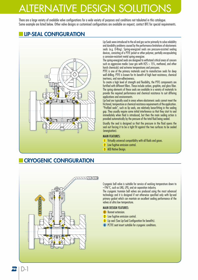
ALTERNATIVE DESIGN SOLUTIONSThere are a large variety of available valve configurations for a wide variety of purposes and conditions not tabulated in this catalogue. Some example are listed below. Other valve designs or customised configurations are available on request, contact BFE for special requirements.
LIP-SEAL CONFIGURATIONLip-Seals were introduced to the oil and gas sector primarily to solve reliability and durability problems caused by the performance limitations of elastomeric seals (e.g. O-Ring). Spring-energized seals are pressure-assisted sealing devices, consisting of a PTFE jacket or other polymer, partially encapsulating a corrosion-resistant metal spring energizer.The spring-energized seals are designed to withstand critical areas of concern such as aggressive media (sour gas with H2S > 15%, methanol, and other harsh chemicals) and extreme temperatures and pressures.PTFE is one of the primary materials used to manufacture seals for deep well drilling. PTFE is known for its benefit of high heat resistance, chemical inertness, and non-adhesiveness. To create a high level of strength and flexibility, the PTFE components are fortified with different fillers. These include carbon, graphite, and glass fiber. The spring elements of these seals are available in a variety of materials to provide the required performance and chemical resistance to suit differing applications and environments.Lip-Seal are typically used in areas where elastomeric seals cannot meet the frictional, temperature or chemical resistance requirements of the application. “Profiled seals”, such as lip seals, are relatively loose-fitting in the sealing gap. They usually require some initial interference so that they start to seal immediately when fluid is introduced, but then the main sealing action is provided automatically by the pressure of the total fluid being sealed. Usually the seal is designed so that the pressure in the fluid opens the seal out forcing it to be a tight fit against the two surfaces to be sealed (energisation).
MAIN FEATURES:1 Virtually universal compatibility with all fluids and gases.2 Low fugitive emission control.3 AED Native Design.
CRYOGENIC CONFIGURATION
Cryogenic ball valve is suitable for service of working temperature down to –196°C, such as LNG, LPG, and air separation industry.The cryogenic trunnion ball valves are produced using the most advanced technology and it is designed if not otherwise specified only with lip-seal primary gasket which can mantain an excellent sealing performance of the valves at ultra low temperature.
MAIN DESIGN FEATURES:1 Bonnet extension.2 Low fugitive emission control.3 Lip seal (See Lip-Seal Configuration for benefits).4 PCTFE seat insert suitable for cryogenic conditions.
EXTE
NSI
ON
D-1
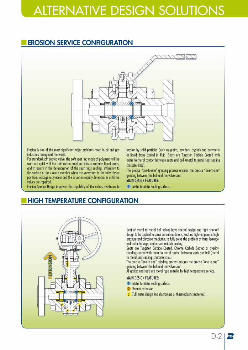
ALTERNATIVE DESIGN SOLUTIONS
EROSION SERVICE CONFIGURATION
HIGH TEMPERATURE CONFIGURATION
Seat of metal to metal ball valves have special design and tight shut-off design to be applied to some critical conditions, such as high-temperate, high pressure and abrasive mediums, to fully solve the problem of inner leakage and outer leakage, and ensure reliable sealing.Seats are Tungsten Carbide Coated, Chrome Carbide Coated or overlay cladding coated with metal to metal contact between seats and ball (metal to metal seat sealing characteristics). The precise “one-to-one” grinding process ensures the precise “one-to-one” grinding between the ball and the valve seat.All gasket and seals are metal type suitalbe for high temperature service.
MAIN DESIGN FEATURES:1 Metal to Metal sealing surface.2 Bonnet extension.3 Full metal design (no elastomers or thermoplastic materials).
Erosion is one of the most significant major problems faced in oil and gas industries throughout the world.For standard soft seated valve, the soft seat ring made of polymers will be worn out quickly, if the fluid carries solid particles or contains liquid drops, and it results in the deterioration of the seat rings sealing efficiency to the surface of the closure member when the valves are in the fully closed position, leakage may occur and the situation rapidly deteriorates until the valves are repaired.Erosion Service Design improves the capability of the valves resistance to
erosion by solid particles (such as grains, powders, crystals and polymers) or liquid drops carried in fluid. Seats are Tungsten Carbide Coated with metal to metal contact between seats and ball (metal to metal seat sealing characteristics). The precise “one-to-one” grinding process ensures the precise “one-to-one” grinding between the ball and the valve seat.MAIN DESIGN FEATURES:1 Metal to Metal sealing surface.
EXTE
NSI
ON
D-2
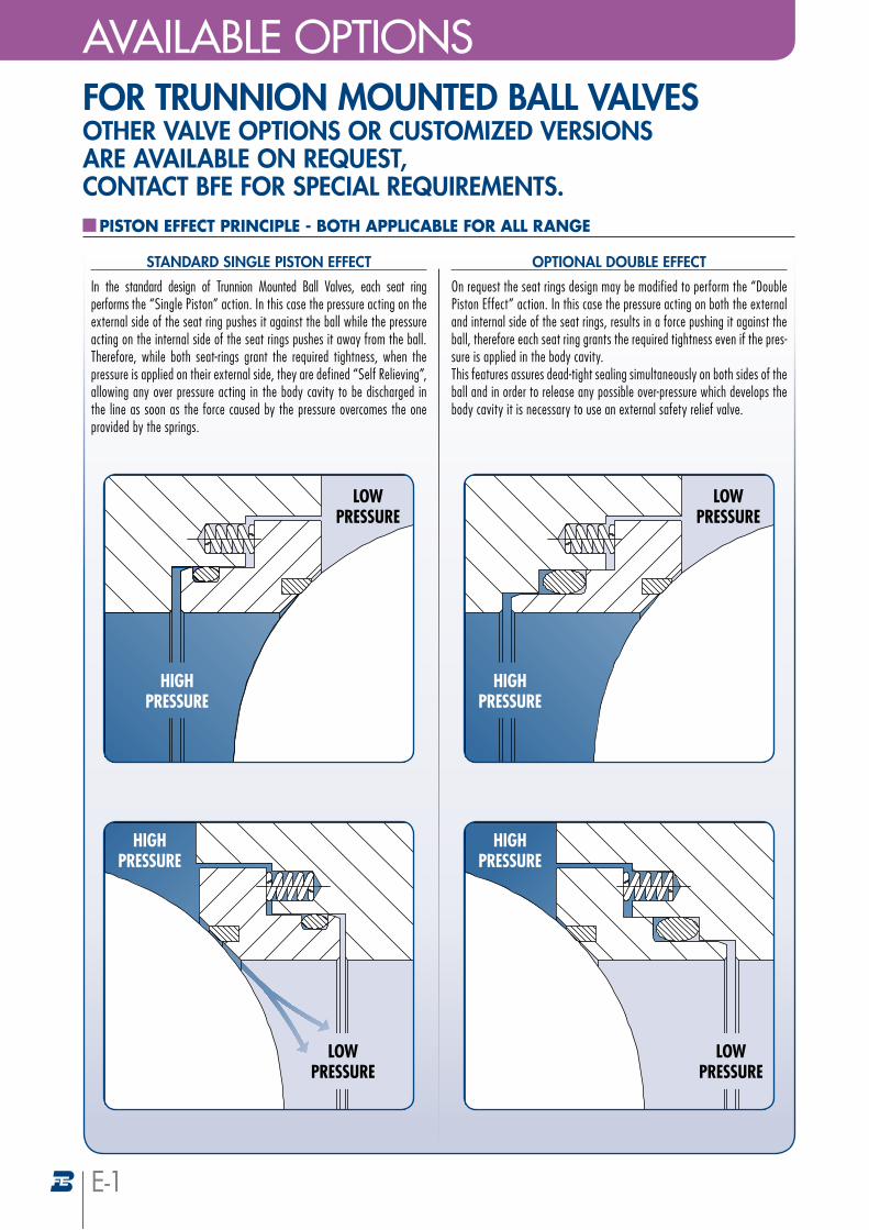
FOR TRUNNION MOUNTED BALL VALVES OTHER VALVE OPTIONS OR CUSTOMIZED VERSIONS ARE AVAILABLE ON REQUEST, CONTACT BFE FOR SPECIAL REQUIREMENTS.
PISTON EFFECT PRINCIPLE - BOTH APPLICABLE FOR ALL RANGE
E-1
In the standard design of Trunnion Mounted Ball Valves, each seat ring performs the “Single Piston” action. In this case the pressure acting on the external side of the seat ring pushes it against the ball while the pressure acting on the internal side of the seat rings pushes it away from the ball. Therefore, while both seat-rings grant the required tightness, when the pressure is applied on their external side, they are defined “Self Relieving”, allowing any over pressure acting in the body cavity to be discharged in the line as soon as the force caused by the pressure overcomes the one provided by the springs.
STANDARD SINGLE PISTON EFFECT
On request the seat rings design may be modified to perform the “Double Piston Effect” action. In this case the pressure acting on both the external and internal side of the seat rings, results in a force pushing it against the ball, therefore each seat ring grants the required tightness even if the pres-sure is applied in the body cavity. This features assures dead-tight sealing simultaneously on both sides of the ball and in order to release any possible over-pressure which develops the body cavity it is necessary to use an external safety relief valve.
OPTIONAL DOUBLE EFFECT
lowpressure
highpressure
lowpressure
highpressure
highpressure
lowpressure
highpressure
lowpressure
AVAILABLE OPTIONS
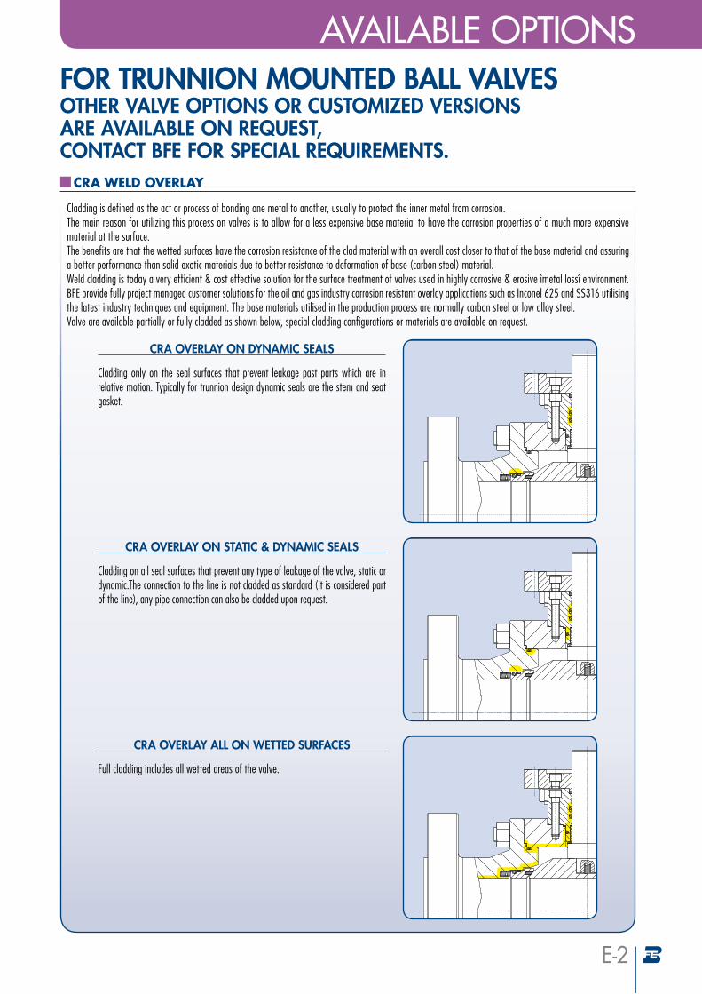
FOR TRUNNION MOUNTED BALL VALVES OTHER VALVE OPTIONS OR CUSTOMIZED VERSIONS ARE AVAILABLE ON REQUEST, CONTACT BFE FOR SPECIAL REQUIREMENTS.
CRA WELD OVERLAY
Cladding is defined as the act or process of bonding one metal to another, usually to protect the inner metal from corrosion. The main reason for utilizing this process on valves is to allow for a less expensive base material to have the corrosion properties of a much more expensive material at the surface. The benefits are that the wetted surfaces have the corrosion resistance of the clad material with an overall cost closer to that of the base material and assuring a better performance than solid exotic materials due to better resistance to deformation of base (carbon steel) material. Weld cladding is today a very efficient & cost effective solution for the surface treatment of valves used in highly corrosive & erosive ìmetal lossî environment. BFE provide fully project managed customer solutions for the oil and gas industry corrosion resistant overlay applications such as Inconel 625 and SS316 utilising the latest industry techniques and equipment. The base materials utilised in the production process are normally carbon steel or low alloy steel. Valve are available partially or fully cladded as shown below, special cladding configurations or materials are available on request.
CRA OVERLAY ON DYNAMIC SEALS
Cladding only on the seal surfaces that prevent leakage past parts which are in relative motion. Typically for trunnion design dynamic seals are the stem and seat gasket.
CRA OVERLAY ON STATIC & DYNAMIC SEALS
Cladding on all seal surfaces that prevent any type of leakage of the valve, static or dynamic.The connection to the line is not cladded as standard (it is considered part of the line), any pipe connection can also be cladded upon request.
CRA OVERLAY ALL ON WETTED SURFACES
Full cladding includes all wetted areas of the valve.
E-2
AVAILABLE OPTIONS
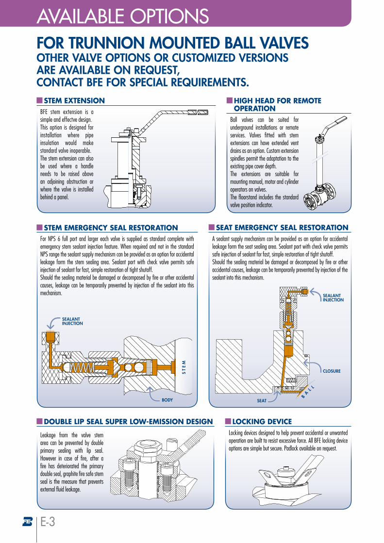
HIGH HEAD FOR REMOTE OPERATION
Ball valves can be suited for underground installations or remote services. Valves fitted with stem extensions can have extended vent drains as an option. Custom extension spindles permit the adaptation to the existing pipe cover depth. The extensions are suitable for mounting manual, motor and cylinder operators on valves. The floorstand includes the standard valve position indicator.
STEM EXTENSIONBFE stem extension is a simple and effectve design.This option is designed for installation where pipe insulation would make standard valve inoperable.The stem extension can also be used where a handle needs to be raised above an adjoining obstruction or where the valve is installed behind a panel.
STEM EMERGENCY SEAL RESTORATIONFor NPS 6 full port and larger each valve is supplied as standard complete with emergency stem sealant injection feature. When required and not in the standard NPS range the sealant supply mechanism can be provided as an option for accidental leakage form the stem sealing area. Sealant port with check valve permits safe injection of sealant for fast, simple restoration of tight shutoff. Should the sealing material be damaged or decomposed by fire or other accidental causes, leakage can be temporarily prevented by injection of the sealant into this mechanism.
SEALANTINJECTION
BODY
ST
EM
SEAT EMERGENCY SEAL RESTORATIONA sealant supply mechanism can be provided as an option for accidental leakage form the seat sealing area. Sealant port with check valve permits safe injection of sealant for fast, simple restoration of tight shutoff. Should the sealing material be damaged or decomposed by fire or other accidental causes, leakage can be temporarily prevented by injection of the sealant into this mechanism.
SEALANTINJECTION
CLOSURE
SEAT
LOCKING DEVICELocking devices designed to help prevent accidental or unwanted operation are built to resist excessive force. All BFE locking device options are simple but secure. Padlock available on request.
E-3
DOUBLE LIP SEAL SUPER LOW-EMISSION DESIGN
Leakage from the valve stem area can be prevented by double primary sealing with lip seal. However in case of fire, after a fire has deteriorated the primary double seal, graphite fire safe stem seal is the measure that prevents external fluid leakage.
FOR TRUNNION MOUNTED BALL VALVES OTHER VALVE OPTIONS OR CUSTOMIZED VERSIONS ARE AVAILABLE ON REQUEST, CONTACT BFE FOR SPECIAL REQUIREMENTS.
AVAILABLE OPTIONS
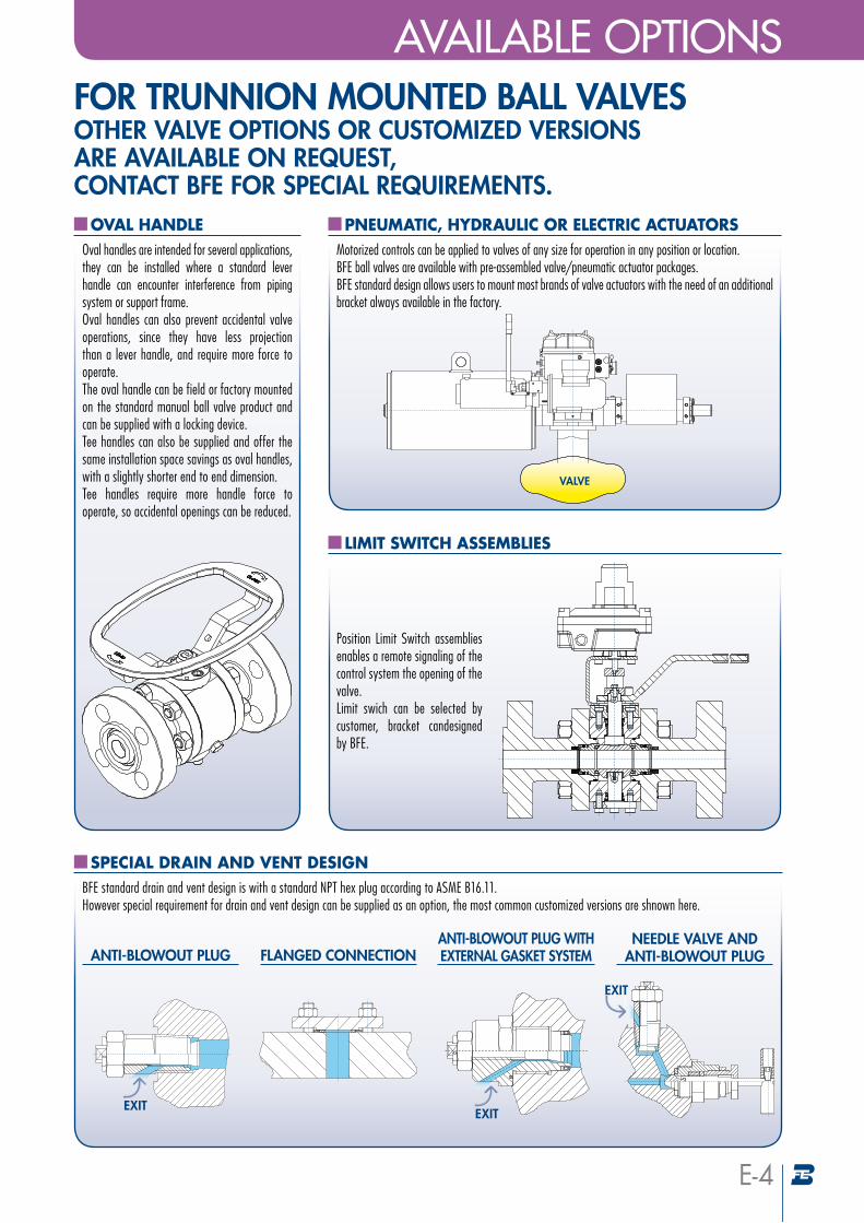
OVAL HANDLEOval handles are intended for several applications, they can be installed where a standard lever handle can encounter interference from piping system or support frame. Oval handles can also prevent accidental valve operations, since they have less projection than a lever handle, and require more force to operate. The oval handle can be field or factory mounted on the standard manual ball valve product and can be supplied with a locking device. Tee handles can also be supplied and offer the same installation space savings as oval handles, with a slightly shorter end to end dimension. Tee handles require more handle force to operate, so accidental openings can be reduced.
LIMIT SWITCH ASSEMBLIES
Position Limit Switch assemblies enables a remote signaling of the control system the opening of the valve. Limit swich can be selected by customer, bracket candesigned by BFE.
PNEUMATIC, HYDRAULIC OR ELECTRIC ACTUATORSMotorized controls can be applied to valves of any size for operation in any position or location. BFE ball valves are available with pre-assembled valve/pneumatic actuator packages. BFE standard design allows users to mount most brands of valve actuators with the need of an additional bracket always available in the factory.
VALVE
SPECIAL DRAIN AND VENT DESIGNBFE standard drain and vent design is with a standard NPT hex plug according to ASME B16.11. However special requirement for drain and vent design can be supplied as an option, the most common customized versions are shnown here.
FLANGED CONNECTIONNEEDLE VALVE AND
ANTI-BLOWOUT PLUG
EXIT
ANTI-BLOWOUT PLUG WITH EXTERNAL GASKET SYSTEM
EXIT
ANTI-BLOWOUT PLUG
EXIT
E-4
FOR TRUNNION MOUNTED BALL VALVES OTHER VALVE OPTIONS OR CUSTOMIZED VERSIONS ARE AVAILABLE ON REQUEST, CONTACT BFE FOR SPECIAL REQUIREMENTS.
AVAILABLE OPTIONS

Printed in Italy 1th edition. Revision 00 2017/01/31
The material in this catalog is for general information. For specific performance data and proper product selection, consult BFE or your BFE representative. BFE reserves the right to change designs, dimensions or specifications without notice.
QUOTATION VALIDITY
Unless otherwise agreed, quotations are valid for four weeks from date of issue. The delivery terms are always “ex-works” unless otherwise stated.Prices and sale conditions can be changed without any previous notice.
ORDERS ACCEPTANCE
Orders are considered accepted at our general sale conditions clearly mentioned on order acknowledgment.
GOODS DELIVERY
The Company does not accept any responsability for delays is delivery which are always intended as indicative and not binding. Transport risks are at receiver’s charge also in case of CIF delivery.
GUARANTEE
The Company warrantees all its products, from material and/or manufacturing defects, to be used as recommended by standards, and in accordance with approved piping practice and technique, for a period of one year from shipping date, unless otherwise agreed.The Company liability covers eventual “free of charge” replacements for defective parts or products, providing it has not failed in the observance of above mentioned conditions and in use in compliance with standards, and, anyway, after return of defective goods. Any other liability, neither objective nor subjective will be accepted.
CLAIMS AND ORDER CANCELLATIONS
Claims will be considered only if made within 10 days from goods receipt.Partial or complete cancellations of order can be accepted only upon previous agreement or by written consent and, however, not later than 15 days from order date. Any controversy will be handled by the Court of Milan.
GENERAL SALE CONDITIONS
B.F.E. S.r.l. - Via Tonale, 70/A - 24061 Albano S.Alessandro (BG) Italy - Phone: 035.584111 - Fax: 035.583022 - Mail: [email protected]
www.bfe.it
+001.814.542.2545www.bonneyforge.com
www.rpc-valve.com+001.713.695.3633 - +001.713.695.3528 fwww.wfi-intl.com