Embed Size (px)
Citation preview
R
TransNav Provisioning
TR4.0.x/TN5.0.x June 2011
Guide

Copyright © 2011 Force10 Networks, Inc.
All rights reserved. Force10 Networks ® reserves the right to change, modify, revise this publication without notice.
Trademarks
Force10 Networks® and E-Series® are registered trademarks of Force10 Networks, Inc.
Traverse, TraverseEdge, TraversePacketEdge, TransAccess, are registered trademarks of Force10 Networks, Inc. Force10, the Force10 logo, and TransNav are trademarks of Force10 Networks, Inc. or its affiliates in the United States and other countries and are protected by U.S. and international copyright laws. All other brand and product names are registered trademarks or trademarks of their respective holders.
Statement of Conditions
In the interest of improving internal design, operational function, and/or reliability, Force10 Networks, Inc. reserves the right to make changes to products described in this document without notice. Force10 Networks, Inc. does not assume any liability that may occur due to the use or application of the product(s) described herein.
CONTENTS
Chapter 1 TN5.0.x Provisioning Overview
Configuration Process . . . . . . . . . . . . . . . . . . . . . . . . . . . . . . . . . . . . . . . . . . 1
Guidelines to Switching Card or Port Types. . . . . . . . . . . . . . . . . . . . . . . . . . 2
Chapter 2Discover the Network
Before You Start Provisioning Your Network . . . . . . . . . . . . . . . . . . . . . . . . . 1
Discover the Network . . . . . . . . . . . . . . . . . . . . . . . . . . . . . . . . . . . . . . . . . . . 2
Configure Node Parameters. . . . . . . . . . . . . . . . . . . . . . . . . . . . . . . . . . . . . . 4
Chapter 3Configure Network Timing
Introduction. . . . . . . . . . . . . . . . . . . . . . . . . . . . . . . . . . . . . . . . . . . . . . . . . . . 1
Global Timing Options . . . . . . . . . . . . . . . . . . . . . . . . . . . . . . . . . . . . . . . . . . 2
External Timing . . . . . . . . . . . . . . . . . . . . . . . . . . . . . . . . . . . . . . . . . . . . . . . 3
Line Timing. . . . . . . . . . . . . . . . . . . . . . . . . . . . . . . . . . . . . . . . . . . . . . . . . . . 6
Line Facility Data . . . . . . . . . . . . . . . . . . . . . . . . . . . . . . . . . . . . . . . . . . . . . . 7
Reference List Options. . . . . . . . . . . . . . . . . . . . . . . . . . . . . . . . . . . . . . . . . . 8
Derived Timing . . . . . . . . . . . . . . . . . . . . . . . . . . . . . . . . . . . . . . . . . . . . . . . . 8
Protection Switching External Timing References . . . . . . . . . . . . . . . . . . . . . 9
Protection Switching Line Timing References . . . . . . . . . . . . . . . . . . . . . . . . 10
Before You Configure Timing . . . . . . . . . . . . . . . . . . . . . . . . . . . . . . . . . . . . . 11
Network Timing Examples . . . . . . . . . . . . . . . . . . . . . . . . . . . . . . . . . . . . . . . 12
Guidelines to Configuring Network Timing . . . . . . . . . . . . . . . . . . . . . . . . . . . 14
Configure Global Timing Options . . . . . . . . . . . . . . . . . . . . . . . . . . . . . . . . . . 14
Configure External Timing . . . . . . . . . . . . . . . . . . . . . . . . . . . . . . . . . . . . . . . 15
Configure Line Timing . . . . . . . . . . . . . . . . . . . . . . . . . . . . . . . . . . . . . . . . . . 18
Configure Derived References . . . . . . . . . . . . . . . . . . . . . . . . . . . . . . . . . . . . 19
Chapter 4Creating DCC Tunnels
DCC Tunnel Example. . . . . . . . . . . . . . . . . . . . . . . . . . . . . . . . . . . . . . . . . . . 2
Before You Tunnel a DCC . . . . . . . . . . . . . . . . . . . . . . . . . . . . . . . . . . . . . . . 3
Disable Control Data Procedure. . . . . . . . . . . . . . . . . . . . . . . . . . . . . . . . . . . 5
Tunneling a DCC Through a Traverse Network . . . . . . . . . . . . . . . . . . . . . . . 6
DCC Tunnel Tab . . . . . . . . . . . . . . . . . . . . . . . . . . . . . . . . . . . . . . . . . . . . . . 9
Chapter 5Configuring IP Quality of Service
Before You Configure IP Quality of Service . . . . . . . . . . . . . . . . . . . . . . . . . . 2
Configuring IP Quality of Service . . . . . . . . . . . . . . . . . . . . . . . . . . . . . . . . . . 2
TransNav Management System Provisioning Guide, Release TN5.0.x 1
Global Parameters Tab. . . . . . . . . . . . . . . . . . . . . . . . . . . . . . . . . . . . . . . . . . 6
Static Classifier Tab . . . . . . . . . . . . . . . . . . . . . . . . . . . . . . . . . . . . . . . . . . . . 7
Dynamic Classifier Tab. . . . . . . . . . . . . . . . . . . . . . . . . . . . . . . . . . . . . . . . . . 9
ACL (Access Control) Tab . . . . . . . . . . . . . . . . . . . . . . . . . . . . . . . . . . . . . . . 10
Statistics Tab . . . . . . . . . . . . . . . . . . . . . . . . . . . . . . . . . . . . . . . . . . . . . . . . . 12
Chapter 6Creating a Traverse OSI Gateway Node
Example of the Traverse OSI Gateway Application . . . . . . . . . . . . . . . . . . . . 1
Supported Protocol Stack . . . . . . . . . . . . . . . . . . . . . . . . . . . . . . . . . . . . . . . . 3
Before You Create a Traverse OSI Gateway Node . . . . . . . . . . . . . . . . . . . . 3
Procedures Required to Create a Traverse OSI Gateway . . . . . . . . . . . . . . . 4
Configure the Optical Interface to Use LAPD . . . . . . . . . . . . . . . . . . . . . . . . . 5
NET Tab . . . . . . . . . . . . . . . . . . . . . . . . . . . . . . . . . . . . . . . . . . . . . . . . . . . . . 6
TTD Port Tab . . . . . . . . . . . . . . . . . . . . . . . . . . . . . . . . . . . . . . . . . . . . . . . . . 7
TTD ACL Tab . . . . . . . . . . . . . . . . . . . . . . . . . . . . . . . . . . . . . . . . . . . . . . . . . 8
TTD Tab . . . . . . . . . . . . . . . . . . . . . . . . . . . . . . . . . . . . . . . . . . . . . . . . . . . . . 9
Man Area Tab . . . . . . . . . . . . . . . . . . . . . . . . . . . . . . . . . . . . . . . . . . . . . . . . . 10
Chapter 7Network Auto Discovery
Network Auto Discovery . . . . . . . . . . . . . . . . . . . . . . . . . . . . . . . . . . . . . . . . . 1
Static Route Information List. . . . . . . . . . . . . . . . . . . . . . . . . . . . . . . . . . . . . . 3
Chapter 8Equipment Overview
When to Change Card Parameters. . . . . . . . . . . . . . . . . . . . . . . . . . . . . . . . . 1
Protection Groups and Card Configuration. . . . . . . . . . . . . . . . . . . . . . . . . . . 1
Equipment States . . . . . . . . . . . . . . . . . . . . . . . . . . . . . . . . . . . . . . . . . . . . . . 2
Common Card and Port Configuration Parameters . . . . . . . . . . . . . . . . . . . . 3
GCM Card Parameters . . . . . . . . . . . . . . . . . . . . . . . . . . . . . . . . . . . . . . . . . . 5
Change Card Common Parameters . . . . . . . . . . . . . . . . . . . . . . . . . . . . . . . . 6
Configure Protection Parameters . . . . . . . . . . . . . . . . . . . . . . . . . . . . . . . . . . 7
Viewing Port Status Values on SONET and SDH. . . . . . . . . . . . . . . . . . . . . . 9
Chapter 9Creating and Deleting Equipment
Auto-discovery and Pre-provisioning . . . . . . . . . . . . . . . . . . . . . . . . . . . . . . . 1
Create a Node . . . . . . . . . . . . . . . . . . . . . . . . . . . . . . . . . . . . . . . . . . . . . . . . 2
Node Parameters . . . . . . . . . . . . . . . . . . . . . . . . . . . . . . . . . . . . . . . . . . . . . . 3
Delete a Node. . . . . . . . . . . . . . . . . . . . . . . . . . . . . . . . . . . . . . . . . . . . . . . . . 7
Card Placement . . . . . . . . . . . . . . . . . . . . . . . . . . . . . . . . . . . . . . . . . . . . . . . 8
Creating, Replacing, or Deleting a Card . . . . . . . . . . . . . . . . . . . . . . . . . . . . . 8
Add a Card . . . . . . . . . . . . . . . . . . . . . . . . . . . . . . . . . . . . . . . . . . . . . . . . . . . 8
Delete a Card . . . . . . . . . . . . . . . . . . . . . . . . . . . . . . . . . . . . . . . . . . . . . . . . . 9
Replace a Card. . . . . . . . . . . . . . . . . . . . . . . . . . . . . . . . . . . . . . . . . . . . . . . . 10
Creating or Deleting Links. . . . . . . . . . . . . . . . . . . . . . . . . . . . . . . . . . . . . . . . 11
Add a Link. . . . . . . . . . . . . . . . . . . . . . . . . . . . . . . . . . . . . . . . . . . . . . . . . . . . 11
2 TransNav Management System Provisioning Guide, Release TN5.0.x
View Available Resources on a Link . . . . . . . . . . . . . . . . . . . . . . . . . . . . . . . 14
Delete a Link . . . . . . . . . . . . . . . . . . . . . . . . . . . . . . . . . . . . . . . . . . . . . . . . . 15
Chapter 10Configuring SONET Equipment
Before You Change SONET Equipment Configurations . . . . . . . . . . . . . . . . 2
DS1 Numbering . . . . . . . . . . . . . . . . . . . . . . . . . . . . . . . . . . . . . . . . . . . . . . . 3
DS1 Mapping . . . . . . . . . . . . . . . . . . . . . . . . . . . . . . . . . . . . . . . . . . . . . . . . . 4
DS3 Framing Format . . . . . . . . . . . . . . . . . . . . . . . . . . . . . . . . . . . . . . . . . . . 4
Informational Parameters . . . . . . . . . . . . . . . . . . . . . . . . . . . . . . . . . . . . . . . . 4
Switching a Card or Port Type . . . . . . . . . . . . . . . . . . . . . . . . . . . . . . . . . . . . 4
Change DS1 Mapping Formats . . . . . . . . . . . . . . . . . . . . . . . . . . . . . . . . . . . 5
Configure TE-100 Interface Module SONET Parameters . . . . . . . . . . . . . . . 7
Configure DS1 Port . . . . . . . . . . . . . . . . . . . . . . . . . . . . . . . . . . . . . . . . . . . . 8
Configure DS3 Clear Channel Ports . . . . . . . . . . . . . . . . . . . . . . . . . . . . . . . 11
Configure DS3TMX or STS1TMX Port. . . . . . . . . . . . . . . . . . . . . . . . . . . . . . 15
Configure Subports . . . . . . . . . . . . . . . . . . . . . . . . . . . . . . . . . . . . . . . . . . . . 19
Configure EC1 Ports . . . . . . . . . . . . . . . . . . . . . . . . . . . . . . . . . . . . . . . . . . . 21
Change the BER Thresholds for an STS Path . . . . . . . . . . . . . . . . . . . . . . . . 26
Configure SONET Ports . . . . . . . . . . . . . . . . . . . . . . . . . . . . . . . . . . . . . . . . . 28
SONET (OC-N) Card Parameters . . . . . . . . . . . . . . . . . . . . . . . . . . . . . . . . . 36
SONET Port Parameters . . . . . . . . . . . . . . . . . . . . . . . . . . . . . . . . . . . . . . . . 37
Chapter 11Configuring SDH Equipment
Before You Configure SDH Equipment . . . . . . . . . . . . . . . . . . . . . . . . . . . . . 2
E1 Card Parameters. . . . . . . . . . . . . . . . . . . . . . . . . . . . . . . . . . . . . . . . . . . . 3
E1 Numbering (Traverse only) . . . . . . . . . . . . . . . . . . . . . . . . . . . . . . . . . . . . 3
E1 Mapping . . . . . . . . . . . . . . . . . . . . . . . . . . . . . . . . . . . . . . . . . . . . . . . . . . 4
E1 Mapping and Patch Panel Ports (Traverse only) . . . . . . . . . . . . . . . . . . . 6
Change E1 Mapping Formats . . . . . . . . . . . . . . . . . . . . . . . . . . . . . . . . . . . . 7
Configure E1 Ports . . . . . . . . . . . . . . . . . . . . . . . . . . . . . . . . . . . . . . . . . . . . . 8
Configure E3 Clear Channel Ports . . . . . . . . . . . . . . . . . . . . . . . . . . . . . . . . . 10
Switching E1 Cards or Ports . . . . . . . . . . . . . . . . . . . . . . . . . . . . . . . . . . . . . 12
Configure the BER Thresholds for an STM Path . . . . . . . . . . . . . . . . . . . . . . 13
Configure STM-N Port Parameters . . . . . . . . . . . . . . . . . . . . . . . . . . . . . . . . 15
SDH (STM) Card Parameters . . . . . . . . . . . . . . . . . . . . . . . . . . . . . . . . . . . . 22
STM Port Parameters. . . . . . . . . . . . . . . . . . . . . . . . . . . . . . . . . . . . . . . . . . . 23
TE-100 Interface Card Parameters . . . . . . . . . . . . . . . . . . . . . . . . . . . . . . . . 27
Chapter 12Configuring Ethernet Equipment
TransNav Management System Provisioning Guide, Release TN5.0.x 3
Before You Begin . . . . . . . . . . . . . . . . . . . . . . . . . . . . . . . . . . . . . . . . . . . . . . 2
Configure Ethernet Cards . . . . . . . . . . . . . . . . . . . . . . . . . . . . . . . . . . . . . . . . 3
Configure Ethernet Port Parameter Values . . . . . . . . . . . . . . . . . . . . . . . . . . 6
Link OAM on an Ethernet Port . . . . . . . . . . . . . . . . . . . . . . . . . . . . . . . . . . . . 12
Configuring Link OAM on an Ethernet Port. . . . . . . . . . . . . . . . . . . . . . . . . . . 14
Auto Negotiation . . . . . . . . . . . . . . . . . . . . . . . . . . . . . . . . . . . . . . . . . . . . . . . 17
Configure Auto Negotiation. . . . . . . . . . . . . . . . . . . . . . . . . . . . . . . . . . . . . . . 19
View the SFP / XFP Port Parameters . . . . . . . . . . . . . . . . . . . . . . . . . . . . . . . 25
View the Diagnostic Parameters. . . . . . . . . . . . . . . . . . . . . . . . . . . . . . . . . . . 27
View the Negotiated Status of a Link . . . . . . . . . . . . . . . . . . . . . . . . . . . . . . . 29
View or Edit the MAC Address Table . . . . . . . . . . . . . . . . . . . . . . . . . . . . . . . 30
Ethernet or EOS Port Queues . . . . . . . . . . . . . . . . . . . . . . . . . . . . . . . . . . . . 33
Chapter 13Configuring a TransAccess 200 Mux
Before You Add a TransAccess 200 Mux. . . . . . . . . . . . . . . . . . . . . . . . . . . . 1
Add TransAccess 200 Mux to the User Interface . . . . . . . . . . . . . . . . . . . . . . 3
TransNav System Parameters . . . . . . . . . . . . . . . . . . . . . . . . . . . . . . . . . . . . 7
Menu Options on the Sub Shelf Menu . . . . . . . . . . . . . . . . . . . . . . . . . . . . . . 7
Navigate to a TransAccess 200 Mux . . . . . . . . . . . . . . . . . . . . . . . . . . . . . . . 9
Delete a TransAccess 200 Mux . . . . . . . . . . . . . . . . . . . . . . . . . . . . . . . . . . . 9
Chapter 14Creating a TraverseEdge 50
Before You Add a TE-50. . . . . . . . . . . . . . . . . . . . . . . . . . . . . . . . . . . . . . . . . 1
Add a TE-50 to the User Interface . . . . . . . . . . . . . . . . . . . . . . . . . . . . . . . . . 3
Delete a TE-50 . . . . . . . . . . . . . . . . . . . . . . . . . . . . . . . . . . . . . . . . . . . . . . . . 4
TransNav System Parameters . . . . . . . . . . . . . . . . . . . . . . . . . . . . . . . . . . . . 4
Navigate to the TE-50 Menu Options . . . . . . . . . . . . . . . . . . . . . . . . . . . . . . . 5
Chapter 15Overview of Protection Groups
1:N Equipment Protection. . . . . . . . . . . . . . . . . . . . . . . . . . . . . . . . . . . . . . . . 2
Optical GbE Port Protection . . . . . . . . . . . . . . . . . . . . . . . . . . . . . . . . . . . . . . 2
Carrier Ethernet Protection . . . . . . . . . . . . . . . . . . . . . . . . . . . . . . . . . . . . . . . 3
Line Protection . . . . . . . . . . . . . . . . . . . . . . . . . . . . . . . . . . . . . . . . . . . . . . . . 4
Path Protection . . . . . . . . . . . . . . . . . . . . . . . . . . . . . . . . . . . . . . . . . . . . . . . . 5
Chapter 16Creating a BLSR/MS-SPRing Protection Group
Example of a BLSR/ MS-SPRing . . . . . . . . . . . . . . . . . . . . . . . . . . . . . . . . . . 2
Before You Create a BLSR or MS-SPRing. . . . . . . . . . . . . . . . . . . . . . . . . . . 3
Guidelines to Create a BLSR or MS-SPRing Protection Group . . . . . . . . . . . 4
Create a BLSR or MS-SPRing Protection Group . . . . . . . . . . . . . . . . . . . . . . 5
Operations Menu . . . . . . . . . . . . . . . . . . . . . . . . . . . . . . . . . . . . . . . . . . . . . . 9
Protection Switch Request Priorities. . . . . . . . . . . . . . . . . . . . . . . . . . . . . . . . 10
Viewing the Squelch Table . . . . . . . . . . . . . . . . . . . . . . . . . . . . . . . . . . . . . . . 11
Updating a Topology (Adding a Node) . . . . . . . . . . . . . . . . . . . . . . . . . . . . . . 13
4 TransNav Management System Provisioning Guide, Release TN5.0.x

Chapter 17Creating and Maintaining UPSR or SNCP Ring Protection Groups
Example of a UPSR or an SNCP Ring. . . . . . . . . . . . . . . . . . . . . . . . . . . . . . 2
Before You Create a UPSR or SNCP Ring Protection Group . . . . . . . . . . . . 3
Guidelines to Create a UPSR or SNCP Ring . . . . . . . . . . . . . . . . . . . . . . . . . 4
Create a UPSR or SNCP Ring Protection Group. . . . . . . . . . . . . . . . . . . . . . 5
SNCP/UPSR Protection Switch Commands . . . . . . . . . . . . . . . . . . . . . . . . . 6
Synchronizing, Editing, and Deleting Configured Protection Rings . . . . . . . . 6
Updating a Topology (Adding a Node) . . . . . . . . . . . . . . . . . . . . . . . . . . . . . . 7
Conducting Maintenance on a UPSR or SNCP Ring . . . . . . . . . . . . . . . . . . . 7
Chapter 18Creating Equipment Protection Groups
Before You Configure Equipment Protection . . . . . . . . . . . . . . . . . . . . . . . . . 1
Guidelines to Create an Equipment Protection Group . . . . . . . . . . . . . . . . . . 3
Create an Equipment Protection Group . . . . . . . . . . . . . . . . . . . . . . . . . . . . . 6
Equipment Protection Switch Commands . . . . . . . . . . . . . . . . . . . . . . . . . . . 9
Chapter 19Carrier Ethernet Protection
Before You Configure CEPP . . . . . . . . . . . . . . . . . . . . . . . . . . . . . . . . . . . . . 1
Guidelines to Create a CEPP Protection Group. . . . . . . . . . . . . . . . . . . . . . . 2
Inter-card Link Aggregation Groups . . . . . . . . . . . . . . . . . . . . . . . . . . . . . . . . 4
Create a CEPP Protection Group. . . . . . . . . . . . . . . . . . . . . . . . . . . . . . . . . . 4
Chapter 20Creating a 1+1 APS/MSP Protection Group
Example of a 1+1 APS/MSP Protection Group . . . . . . . . . . . . . . . . . . . . . . . 1
Before You Create a 1+1 APS/MSP Protection Group . . . . . . . . . . . . . . . . . 3
Create a 1+1 APS/MSP Protection Group . . . . . . . . . . . . . . . . . . . . . . . . . . . 5
Switching 1+1 APS Protection Group. . . . . . . . . . . . . . . . . . . . . . . . . . . . . . . 9
Switch Commands . . . . . . . . . . . . . . . . . . . . . . . . . . . . . . . . . . . . . . . . . . . . . 9
Request Priorities for 1+1 APS Protection . . . . . . . . . . . . . . . . . . . . . . . . . . . 10
Chapter 21Creating a 1+1 Path Protection Group
Example of a 1+1 Path Protection Group. . . . . . . . . . . . . . . . . . . . . . . . . . . . 2
Before You Create a 1+1 Path Protection Group. . . . . . . . . . . . . . . . . . . . . . 4
Guidelines to Create a 1+1 Path Protection Group . . . . . . . . . . . . . . . . . . . . 5
Create a 1+1 Path Protection Group . . . . . . . . . . . . . . . . . . . . . . . . . . . . . . . 5
Chapter 22Adding a Node to a Protected Ring Configuration
Diagram of Topology Update . . . . . . . . . . . . . . . . . . . . . . . . . . . . . . . . . . . . . 1
TransNav Management System Provisioning Guide, Release TN5.0.x 5

Before You Update the Topology (Add a Node) . . . . . . . . . . . . . . . . . . . . . . . 2
Add a Node to the Ring . . . . . . . . . . . . . . . . . . . . . . . . . . . . . . . . . . . . . . . . . 3
Add a New Node to the Protection Group. . . . . . . . . . . . . . . . . . . . . . . . . . . . 7
Chapter 23Creating a 1+1 Optimized Protection Group
Before You Create a 1+1 Optimized Protection Group. . . . . . . . . . . . . . . . . . 2
Create a 1+1 Optimized Protection Group . . . . . . . . . . . . . . . . . . . . . . . . . . . 3
Protection Switch Commands. . . . . . . . . . . . . . . . . . . . . . . . . . . . . . . . . . . . . 5
Request Priorities for 1+1 Optimized Protection. . . . . . . . . . . . . . . . . . . . . . . 5
Chapter 24Service Provisioning Concepts
Traverse Services Definition. . . . . . . . . . . . . . . . . . . . . . . . . . . . . . . . . . . . . . 1
Supported Features . . . . . . . . . . . . . . . . . . . . . . . . . . . . . . . . . . . . . . . . . . . . 1
Transport Capacity . . . . . . . . . . . . . . . . . . . . . . . . . . . . . . . . . . . . . . . . . . . . . 4
Traverse Service Types . . . . . . . . . . . . . . . . . . . . . . . . . . . . . . . . . . . . . . . . . 5
End-to-End Services Over Mixed Topologies . . . . . . . . . . . . . . . . . . . . . . . . . 6
Service Creation Models. . . . . . . . . . . . . . . . . . . . . . . . . . . . . . . . . . . . . . . . . 8
Basic ADM Service Creation Process. . . . . . . . . . . . . . . . . . . . . . . . . . . . . . . 10
Before You Start Creating Services . . . . . . . . . . . . . . . . . . . . . . . . . . . . . . . . 11
Chapter 25Managing Services
Service Tab. . . . . . . . . . . . . . . . . . . . . . . . . . . . . . . . . . . . . . . . . . . . . . . . . . . 1
Service Availability Status Audit . . . . . . . . . . . . . . . . . . . . . . . . . . . . . . . . . . . 6
Service Shortcut Menu . . . . . . . . . . . . . . . . . . . . . . . . . . . . . . . . . . . . . . . . . . 6
Working with the Service List . . . . . . . . . . . . . . . . . . . . . . . . . . . . . . . . . . . . . 7
Setting Service Filters . . . . . . . . . . . . . . . . . . . . . . . . . . . . . . . . . . . . . . . . . . . 8
Service Filters, Type Tab . . . . . . . . . . . . . . . . . . . . . . . . . . . . . . . . . . . . . . . . 8
Service Filters, Node Tab . . . . . . . . . . . . . . . . . . . . . . . . . . . . . . . . . . . . . . . . 9
Service Filters, Source Tab. . . . . . . . . . . . . . . . . . . . . . . . . . . . . . . . . . . . . . . 10
Service Filters, Destination Tab . . . . . . . . . . . . . . . . . . . . . . . . . . . . . . . . . . . 11
Service Filters, Customer Tab . . . . . . . . . . . . . . . . . . . . . . . . . . . . . . . . . . . . 12
Chapter 26Common Procedures for Services
For Strict Services, Configure the Path Through the Network . . . . . . . . . . . . 2
Activate or Deactivate a Service. . . . . . . . . . . . . . . . . . . . . . . . . . . . . . . . . . . 4
Duplicate a Service. . . . . . . . . . . . . . . . . . . . . . . . . . . . . . . . . . . . . . . . . . . . . 5
Search for Services . . . . . . . . . . . . . . . . . . . . . . . . . . . . . . . . . . . . . . . . . . . . 8
Choose an Endpoint . . . . . . . . . . . . . . . . . . . . . . . . . . . . . . . . . . . . . . . . . . . . 10
Configure Advanced Parameters (Alphabetic Order) . . . . . . . . . . . . . . . . . . . 11
Chapter 27Configuring SONET Services
6 TransNav Management System Provisioning Guide, Release TN5.0.x
Examples of SONET Services . . . . . . . . . . . . . . . . . . . . . . . . . . . . . . . . . . . . 2
Other SONET Services and Applications. . . . . . . . . . . . . . . . . . . . . . . . . . . . 3
Cards Required to Create SONET Services . . . . . . . . . . . . . . . . . . . . . . . . . 3
Before You Create SONET Services . . . . . . . . . . . . . . . . . . . . . . . . . . . . . . . 4
VT/TU Switch Card Guidelines. . . . . . . . . . . . . . . . . . . . . . . . . . . . . . . . . . . . 5
VTX/VCX Integrated Card Guidelines . . . . . . . . . . . . . . . . . . . . . . . . . . . . . . 6
Guidelines to Provision a SONET VT-Mux Service . . . . . . . . . . . . . . . . . . . . 6
Payload Mapping Parameter . . . . . . . . . . . . . . . . . . . . . . . . . . . . . . . . . . . . . 6
Automatic in Service. . . . . . . . . . . . . . . . . . . . . . . . . . . . . . . . . . . . . . . . . . . . 6
Create a SONET Service . . . . . . . . . . . . . . . . . . . . . . . . . . . . . . . . . . . . . . . . 8
Chapter 28Creating SONET Low Order End-to-End Services and Tunnels
Rules and Limitations for SONET Low Order End-to-End Services. . . . . . . . 2
Types of Low Order Tunnels . . . . . . . . . . . . . . . . . . . . . . . . . . . . . . . . . . . . . 4
Creating SONET Tunnels Manually . . . . . . . . . . . . . . . . . . . . . . . . . . . . . . . . 6
Creating Low Order End-to-End SONET Services. . . . . . . . . . . . . . . . . . . . . 10
Converting Low Order Hop-by-Hop Services . . . . . . . . . . . . . . . . . . . . . . . . . 15
Viewing Tunnel Constraints . . . . . . . . . . . . . . . . . . . . . . . . . . . . . . . . . . . . . . 15
Deactivating Auto Tunnels . . . . . . . . . . . . . . . . . . . . . . . . . . . . . . . . . . . . . . . 16
Chapter 29Configuring SDH Services
Multiplexing Mixed Traffic onto a VC-4 Transport Path . . . . . . . . . . . . . . . . . 2
Cards Required to Create SDH Services . . . . . . . . . . . . . . . . . . . . . . . . . . . . 3
Other SDH Services and Applications . . . . . . . . . . . . . . . . . . . . . . . . . . . . . . 3
Before You Create SDH Services . . . . . . . . . . . . . . . . . . . . . . . . . . . . . . . . . 4
SDH Switching Guidelines . . . . . . . . . . . . . . . . . . . . . . . . . . . . . . . . . . . . . . . 5
Payload Mapping Parameter . . . . . . . . . . . . . . . . . . . . . . . . . . . . . . . . . . . . . 7
Create an SDH Service . . . . . . . . . . . . . . . . . . . . . . . . . . . . . . . . . . . . . . . . . 8
Create a Low Order SDH Service Across Multiple VT/TU Cards. . . . . . . . . . 14
Create an SDH Endpoint or Tunnel Service. . . . . . . . . . . . . . . . . . . . . . . . . . 20
Create an SDH Transport Path Hop-by-Hop . . . . . . . . . . . . . . . . . . . . . . . . . 25
Create an SDH Transport Path End-to-End . . . . . . . . . . . . . . . . . . . . . . . . . . 25
Chapter 30Creating 2-Port OC-48/STM-16 Services
Slot-to-Slot Switching Capacity . . . . . . . . . . . . . . . . . . . . . . . . . . . . . . . . . . . 2
Guidelines to Provision Protected Services . . . . . . . . . . . . . . . . . . . . . . . . . . 2
Protection Groups using the 2-port OC-48/STM-16 Card . . . . . . . . . . . . . . . 3
Protected Services from a 2-port OC-48/STM-16 to a Protected OC-192/ STM-64 Uplink4
Aggregated Services from OC-48 UPSRs to OC-192 Uplinks . . . . . . . . . . . . 5
Guidelines to Create an Aggregate Service from a Subtended OC-48 UPSR 6
Chapter 31Creating 1+1 Path Protected Services
TransNav Management System Provisioning Guide, Release TN5.0.x 7
Path Protection Group Model (SONET) . . . . . . . . . . . . . . . . . . . . . . . . . . . . . 2
Path Protection Group Model (SDH). . . . . . . . . . . . . . . . . . . . . . . . . . . . . . . . 3
High Order Services with Path Protection. . . . . . . . . . . . . . . . . . . . . . . . . . . . 4
Mixed Payloads with High Order Path Protection . . . . . . . . . . . . . . . . . . . . . . 5
Low Order Services with Path Protection . . . . . . . . . . . . . . . . . . . . . . . . . . . . 6
Path Protection over APS-Protected Links . . . . . . . . . . . . . . . . . . . . . . . . . . . 7
Path Protection over MSP-Protected Links. . . . . . . . . . . . . . . . . . . . . . . . . . . 8
Before You Create 1+1 Path Protected Services . . . . . . . . . . . . . . . . . . . . . . 9
Guidelines to Provision 1+1 Path Protected Services . . . . . . . . . . . . . . . . . . 10
Procedures Required to Create a 1+1 Path Protected Service . . . . . . . . . . . 10
Bookend Application . . . . . . . . . . . . . . . . . . . . . . . . . . . . . . . . . . . . . . . . . . . . 11
Guidelines to Create a Bookend Application . . . . . . . . . . . . . . . . . . . . . . . . . 12
Procedures Required to Create a Bookend Application . . . . . . . . . . . . . . . . . 12
Before You Create a 1+1 Path Protection Group . . . . . . . . . . . . . . . . . . . . . . 13
Guidelines to Create a 1+1 Path Protection Group . . . . . . . . . . . . . . . . . . . . 14
Create a 1+1 Path Protection Group . . . . . . . . . . . . . . . . . . . . . . . . . . . . . . . 14
Protection Switching Path Protected Services . . . . . . . . . . . . . . . . . . . . . . . . 16
Chapter 32Bridging and Rolling Services
Bridging and Rolling Services. . . . . . . . . . . . . . . . . . . . . . . . . . . . . . . . . . . . . 1
Bridge and Roll in a UPSR/SNCP Protection Group . . . . . . . . . . . . . . . . . . . 2
Bridge and Roll in a Single 1+1 APS/MPS Protection Group . . . . . . . . . . . . . 3
Guidelines to Create Bridge and Roll Services. . . . . . . . . . . . . . . . . . . . . . . . 4
Procedures Required to Bridge and Roll Services . . . . . . . . . . . . . . . . . . . . . 4
Bridge and Roll Services. . . . . . . . . . . . . . . . . . . . . . . . . . . . . . . . . . . . . . . . . 5
Create a Persistent Bridge Service. . . . . . . . . . . . . . . . . . . . . . . . . . . . . . . . . 6
Chapter 33Creating Drop-and-Continue Services
Drop and Continue Services. . . . . . . . . . . . . . . . . . . . . . . . . . . . . . . . . . . . . . 1
Example of a Drop and Continue Service (SONET). . . . . . . . . . . . . . . . . . . . 3
Example of a Drop and Continue Service (SDH) . . . . . . . . . . . . . . . . . . . . . . 5
Ethernet Services and Drop and Continue Applications. . . . . . . . . . . . . . . . . 6
Cards Required to Create Drop and Continue Service. . . . . . . . . . . . . . . . . . 6
Before You Create a Drop and Continue Service. . . . . . . . . . . . . . . . . . . . . . 6
Guidelines to Provision Drop and Continue Services . . . . . . . . . . . . . . . . . . . 7
Procedures Required to Provision a Drop and Continue Service. . . . . . . . . . 7
Parameters Required to Provision Drop and Continue Services . . . . . . . . . . 8
Chapter 34Creating Services over Interconnected UPSR or SNCP Rings
Services over Interconnected UPSR or SNCP Rings. . . . . . . . . . . . . . . . . . . 1
8 TransNav Management System Provisioning Guide, Release TN5.0.x
Example of a SONET Bi-directional Protected Path . . . . . . . . . . . . . . . . . . . 2
Example of an SDH Bi-directional Protected Path . . . . . . . . . . . . . . . . . . . . . 3
Example of Bi-directional Protected DS1 and VT1.5 Services. . . . . . . . . . . . 4
Example of Bi-directional Protected E1 and VT Services . . . . . . . . . . . . . . . 5
Cards Required at Interconnecting Nodes . . . . . . . . . . . . . . . . . . . . . . . . . . . 6
Before You Create Services over Interconnected Rings . . . . . . . . . . . . . . . . 6
Guidelines to Provision Services over Interconnected Rings. . . . . . . . . . . . . 7
Procedures Required to Provision Services over Interconnected Rings . . . . 7
Chapter 35Creating Transmux Services
G.747 Services. . . . . . . . . . . . . . . . . . . . . . . . . . . . . . . . . . . . . . . . . . . . . . . . 2
Switching DS1s Inside a Channelized DS3 . . . . . . . . . . . . . . . . . . . . . . . . . . 3
Switching E1s Inside a Channelized DS3 . . . . . . . . . . . . . . . . . . . . . . . . . . . 4
Cards Required to Create a Transmux Service . . . . . . . . . . . . . . . . . . . . . . . 5
Before You Create a Transmux Service. . . . . . . . . . . . . . . . . . . . . . . . . . . . . 8
Guidelines to Provision an Optical Transmux Service . . . . . . . . . . . . . . . . . . 9
Procedures Required to Provision an Optical Transmux Service . . . . . . . . . 9
Assign and Configure Transmux Resources . . . . . . . . . . . . . . . . . . . . . . . . . 10
Configure an Optical Transmux Service. . . . . . . . . . . . . . . . . . . . . . . . . . . . . 13
Chapter 36Creating Transparent Services
Example of SONET Transparent Services. . . . . . . . . . . . . . . . . . . . . . . . . . . 2
Example of SDH Transparent Services . . . . . . . . . . . . . . . . . . . . . . . . . . . . . 3
Cards Required to Create a Transparent Service . . . . . . . . . . . . . . . . . . . . . 4
Before You Create a Transparent Service . . . . . . . . . . . . . . . . . . . . . . . . . . . 4
Guidelines to Provision Transparent Services . . . . . . . . . . . . . . . . . . . . . . . . 5
Procedures Required to Create a Transparent Service . . . . . . . . . . . . . . . . . 6
Disable Control Data Parameter on Nodes Linked to Third-Party Equipment 6
Provision the Transparent Service . . . . . . . . . . . . . . . . . . . . . . . . . . . . . . . . . 7
Chapter 37DCS Application Overview
Multi-Shelf DCS Network Example. . . . . . . . . . . . . . . . . . . . . . . . . . . . . . . . . 2
DCS-384 Matrix Shelf. . . . . . . . . . . . . . . . . . . . . . . . . . . . . . . . . . . . . . . . . . . 3
DCS-768 Matrix Shelf. . . . . . . . . . . . . . . . . . . . . . . . . . . . . . . . . . . . . . . . . . . 4
DCS-IO Shelf . . . . . . . . . . . . . . . . . . . . . . . . . . . . . . . . . . . . . . . . . . . . . . . . . 5
Single-Shelf DCS Application Example . . . . . . . . . . . . . . . . . . . . . . . . . . . . . 6
DCS-96 Shelf . . . . . . . . . . . . . . . . . . . . . . . . . . . . . . . . . . . . . . . . . . . . . . . . . 7
MSAID on DCS . . . . . . . . . . . . . . . . . . . . . . . . . . . . . . . . . . . . . . . . . . . . . . . 7
MSAID Allocation . . . . . . . . . . . . . . . . . . . . . . . . . . . . . . . . . . . . . . . . . . . . . . 8
MSAID Assignments . . . . . . . . . . . . . . . . . . . . . . . . . . . . . . . . . . . . . . . . . . . 8
MSAID Formats . . . . . . . . . . . . . . . . . . . . . . . . . . . . . . . . . . . . . . . . . . . . . . . 9
Chapter 38Creating a Single-Shelf DCS Application
TransNav Management System Provisioning Guide, Release TN5.0.x 9
Single-Shelf DCS Network Example. . . . . . . . . . . . . . . . . . . . . . . . . . . . . . . . 2
Guidelines to Create a DCS-96 Application . . . . . . . . . . . . . . . . . . . . . . . . . . 2
Procedure to Create a Single-Shelf DCS Application. . . . . . . . . . . . . . . . . . . 3
DCS-96 MSAID Assignments . . . . . . . . . . . . . . . . . . . . . . . . . . . . . . . . . . . . . 3
DCS Assignment Details. . . . . . . . . . . . . . . . . . . . . . . . . . . . . . . . . . . . . . . . . 4
Assign MSAID Numbers to STS-Equivalents on DCS-96 Shelf . . . . . . . . . . . 5
Create DCS Services on the DCS-96 Shelf . . . . . . . . . . . . . . . . . . . . . . . . . . 8
Activate DCS-96 DCS Services . . . . . . . . . . . . . . . . . . . . . . . . . . . . . . . . . . . 15
Viewing Transmux Information for DCS MSAID Assignments . . . . . . . . . . . . 16
Chapter 39DCS-IO Shelf Configuration
DCS-IO MSAID Allocation . . . . . . . . . . . . . . . . . . . . . . . . . . . . . . . . . . . . . . . 2
DCS-IO MSAID Assignments . . . . . . . . . . . . . . . . . . . . . . . . . . . . . . . . . . . . . 3
DCS-IO Assignment Details . . . . . . . . . . . . . . . . . . . . . . . . . . . . . . . . . . . . . . 5
Chapter 40Creating a Multi-Shelf Application
Multi-Shelf DCS Network Example . . . . . . . . . . . . . . . . . . . . . . . . . . . . . . . . . 2
Shelf Views of a Multi-Shelf DCS Application. . . . . . . . . . . . . . . . . . . . . . . . . 3
Guidelines to Create a Multi-Shelf DCS Application. . . . . . . . . . . . . . . . . . . . 6
Protection Groups on DCS-384 and DCS-768 Matrix Shelves. . . . . . . . . . . . 7
Procedure to Create a Multi-Shelf DCS Application . . . . . . . . . . . . . . . . . . . . 8
DCS-384 and DCS-768 Multi-Shelf MSAID Assignments . . . . . . . . . . . . . . . 9
DCS-384 and DCS-768 MSAID Allocation . . . . . . . . . . . . . . . . . . . . . . . . . . . 11
Allocate MSAID Ranges on DCS-IO Shelf . . . . . . . . . . . . . . . . . . . . . . . . . . . 14
Assign MSAID Number to STS- Equivalents on DCS-IO Shelf . . . . . . . . . . . 16
Activate MSAID Assignments on DCS-IO Shelf . . . . . . . . . . . . . . . . . . . . . . . 20
Create DCS Services on the DCS-384 or DCS-768 Matrix Shelf . . . . . . . . . . 21
Activate DCS-384 or DCS-768 Services. . . . . . . . . . . . . . . . . . . . . . . . . . . . . 24
DCS-384 Fragmentation. . . . . . . . . . . . . . . . . . . . . . . . . . . . . . . . . . . . . . . . . 25
Chapter 41Configuring Ethernet Overview
Ethernet Services Definition . . . . . . . . . . . . . . . . . . . . . . . . . . . . . . . . . . . . . . 2
Line Services . . . . . . . . . . . . . . . . . . . . . . . . . . . . . . . . . . . . . . . . . . . . . . . . . 3
Bridge Services. . . . . . . . . . . . . . . . . . . . . . . . . . . . . . . . . . . . . . . . . . . . . . . . 4
Aggregation Bridge Services . . . . . . . . . . . . . . . . . . . . . . . . . . . . . . . . . . . . . 5
Multipoint ECC Services . . . . . . . . . . . . . . . . . . . . . . . . . . . . . . . . . . . . . . . . . 6
Link Integrity . . . . . . . . . . . . . . . . . . . . . . . . . . . . . . . . . . . . . . . . . . . . . . . . . . 7
Ethernet Configuration Process . . . . . . . . . . . . . . . . . . . . . . . . . . . . . . . . . . . 9
Ethernet Configuration Procedure . . . . . . . . . . . . . . . . . . . . . . . . . . . . . . . . . 10
Configuring CPE to Ethernet Information Flow. . . . . . . . . . . . . . . . . . . . . . . . 11
Configuring CPE to Ethernet Services Procedure . . . . . . . . . . . . . . . . . . . . . 12
Chapter 42Link Aggregation
Link Aggregation. . . . . . . . . . . . . . . . . . . . . . . . . . . . . . . . . . . . . . . . . . . . . . . 1
10 TransNav Management System Provisioning Guide, Release TN5.0.x
Link Aggregation Control Protocol . . . . . . . . . . . . . . . . . . . . . . . . . . . . . . . . . 2
Guidelines to Configure Link Aggregation . . . . . . . . . . . . . . . . . . . . . . . . . . . 2
LAG Capacity Changes . . . . . . . . . . . . . . . . . . . . . . . . . . . . . . . . . . . . . . . . . 3
Before You Begin . . . . . . . . . . . . . . . . . . . . . . . . . . . . . . . . . . . . . . . . . . . . . . 4
Create a Link Aggregation Group. . . . . . . . . . . . . . . . . . . . . . . . . . . . . . . . . . 5
Edit LACP Values. . . . . . . . . . . . . . . . . . . . . . . . . . . . . . . . . . . . . . . . . . . . . . 11
View the Link Aggregation Control Protocol Status of LAG . . . . . . . . . . . . . . 13
Chapter 43Ethernet Over SONET/SDH (EOS)
Ethernet over SONET/SDH Required Connections . . . . . . . . . . . . . . . . . . . . 2
EOS Ports . . . . . . . . . . . . . . . . . . . . . . . . . . . . . . . . . . . . . . . . . . . . . . . . . . . 2
Virtual Concatenation . . . . . . . . . . . . . . . . . . . . . . . . . . . . . . . . . . . . . . . . . . . 3
Guidelines to Configure EOS Ports . . . . . . . . . . . . . . . . . . . . . . . . . . . . . . . . 4
Before You Begin . . . . . . . . . . . . . . . . . . . . . . . . . . . . . . . . . . . . . . . . . . . . . . 6
Configure EOS Port Members . . . . . . . . . . . . . . . . . . . . . . . . . . . . . . . . . . . . 7
Configure Service Groups . . . . . . . . . . . . . . . . . . . . . . . . . . . . . . . . . . . . . . . 7
Creating EOS Ports . . . . . . . . . . . . . . . . . . . . . . . . . . . . . . . . . . . . . . . . . . . . 9
View EOS Port Status . . . . . . . . . . . . . . . . . . . . . . . . . . . . . . . . . . . . . . . . . . 16
Chapter 44EOS Port Protection
Example of EOS Port Protection . . . . . . . . . . . . . . . . . . . . . . . . . . . . . . . . . . 2
Guidelines to Configure EOS Port Protection . . . . . . . . . . . . . . . . . . . . . . . . 3
Before You Begin . . . . . . . . . . . . . . . . . . . . . . . . . . . . . . . . . . . . . . . . . . . . . . 3
Create a 1+1 EOS Port Protection Group . . . . . . . . . . . . . . . . . . . . . . . . . . . 5
Chapter 45Ethernet Over PDH (EOP)
Ethernet over PDH (EOP) Requirements. . . . . . . . . . . . . . . . . . . . . . . . . . . . 1
Virtual Concatenation of PDH Circuits . . . . . . . . . . . . . . . . . . . . . . . . . . . . . . 2
EoPDH Capacity . . . . . . . . . . . . . . . . . . . . . . . . . . . . . . . . . . . . . . . . . . . . . . 3
Guidelines to Configure EOS and EOP Ports on EOPDH Cards. . . . . . . . . . 4
Before You Begin . . . . . . . . . . . . . . . . . . . . . . . . . . . . . . . . . . . . . . . . . . . . . . 7
Creating EOP Ports . . . . . . . . . . . . . . . . . . . . . . . . . . . . . . . . . . . . . . . . . . . . 8
Chapter 46EoPDH Services and Applications
EoPDH Applications . . . . . . . . . . . . . . . . . . . . . . . . . . . . . . . . . . . . . . . . . . . . 1
Configuring CPE to Ethernet Information Flow . . . . . . . . . . . . . . . . . . . . . . . 2
Configuring CPE to EoPDH Services Procedure . . . . . . . . . . . . . . . . . . . . . . 3
Managing Traffic on EOP Ports . . . . . . . . . . . . . . . . . . . . . . . . . . . . . . . . . . . 4
Chapter 47Link Capacity Adjustment Scheme
LCAS Operation . . . . . . . . . . . . . . . . . . . . . . . . . . . . . . . . . . . . . . . . . . . . . . . 2
LCAS and Protection Groups . . . . . . . . . . . . . . . . . . . . . . . . . . . . . . . . . . . . . 4
Asymmetric LCAS . . . . . . . . . . . . . . . . . . . . . . . . . . . . . . . . . . . . . . . . . . . . . 4
TransNav Management System Provisioning Guide, Release TN5.0.x 11
LCAS Interworking . . . . . . . . . . . . . . . . . . . . . . . . . . . . . . . . . . . . . . . . . . . . . 4
Before You Begin . . . . . . . . . . . . . . . . . . . . . . . . . . . . . . . . . . . . . . . . . . . . . . 6
Guidelines to Configure LCAS . . . . . . . . . . . . . . . . . . . . . . . . . . . . . . . . . . . . 6
Guidelines to Removing LCAS EOS Links . . . . . . . . . . . . . . . . . . . . . . . . . . . 6
Configure LCAS . . . . . . . . . . . . . . . . . . . . . . . . . . . . . . . . . . . . . . . . . . . . . . . 8
Chapter 48Rapid Spanning Tree Protocol
What is RSTP? . . . . . . . . . . . . . . . . . . . . . . . . . . . . . . . . . . . . . . . . . . . . . . . . 2
Supported RSTP Topologies . . . . . . . . . . . . . . . . . . . . . . . . . . . . . . . . . . . . . 3
RSTP Bridge Management . . . . . . . . . . . . . . . . . . . . . . . . . . . . . . . . . . . . . . . 4
RSTP Port Management. . . . . . . . . . . . . . . . . . . . . . . . . . . . . . . . . . . . . . . . . 4
Guidelines to Configure RSTP . . . . . . . . . . . . . . . . . . . . . . . . . . . . . . . . . . . . 5
Virtual RSTP . . . . . . . . . . . . . . . . . . . . . . . . . . . . . . . . . . . . . . . . . . . . . . . . . . 7
Before You Begin . . . . . . . . . . . . . . . . . . . . . . . . . . . . . . . . . . . . . . . . . . . . . . 8
Before You Begin Configuring RSTP on TE-100 Nodes. . . . . . . . . . . . . . . . . 9
Configure RSTP on an EOS Port . . . . . . . . . . . . . . . . . . . . . . . . . . . . . . . . . . 10
View RSTP Port Status. . . . . . . . . . . . . . . . . . . . . . . . . . . . . . . . . . . . . . . . . . 12
Configure Virtual RSTP. . . . . . . . . . . . . . . . . . . . . . . . . . . . . . . . . . . . . . . . . . 14
Chapter 49Creating Ethernet Services on Traverse
Guidelines to Configure Ethernet Services on a Traverse Platform . . . . . . . . 2
NGE and EoPDH Capacity . . . . . . . . . . . . . . . . . . . . . . . . . . . . . . . . . . . . . . . 5
Before You Begin . . . . . . . . . . . . . . . . . . . . . . . . . . . . . . . . . . . . . . . . . . . . . . 7
Guaranteed Data Rate and Ethernet Services . . . . . . . . . . . . . . . . . . . . . . . . 7
Configure Ethernet Services. . . . . . . . . . . . . . . . . . . . . . . . . . . . . . . . . . . . . . 9
Chapter 50VLAN Tagging on Traverse Ethernet Services
Supported Types of VLAN Tags . . . . . . . . . . . . . . . . . . . . . . . . . . . . . . . . . . . 2
Ethernet Services and VLAN Tagging . . . . . . . . . . . . . . . . . . . . . . . . . . . . . . 6
VLAN Tagging Guidelines . . . . . . . . . . . . . . . . . . . . . . . . . . . . . . . . . . . . . . . 7
Reserved VLAN IDs . . . . . . . . . . . . . . . . . . . . . . . . . . . . . . . . . . . . . . . . . . . . 7
Determining Services . . . . . . . . . . . . . . . . . . . . . . . . . . . . . . . . . . . . . . . . . . . 8
All Ports in Service are Port-based. . . . . . . . . . . . . . . . . . . . . . . . . . . . . . . . . 10
Mix of Port-based and Service-tagged Ports in a Service . . . . . . . . . . . . . . . 11
All Ports in a Service are Customer-tagged . . . . . . . . . . . . . . . . . . . . . . . . . . 11
Mix of Customer-tagged and Service-tagged Ports in a Service . . . . . . . . . . 13
All Ports in a Service Are Tagged as Service-tagged. . . . . . . . . . . . . . . . . . . 16
VLAN Tagging with Service OAM. . . . . . . . . . . . . . . . . . . . . . . . . . . . . . . . . . 17
View VLAN Usage . . . . . . . . . . . . . . . . . . . . . . . . . . . . . . . . . . . . . . . . . . . . . 19
Chapter 51Configuring Ethernet Service OAM
12 TransNav Management System Provisioning Guide, Release TN5.0.x
Understanding Service OAM . . . . . . . . . . . . . . . . . . . . . . . . . . . . . . . . . . . . . 2
Before You Begin Configuring Service OAM . . . . . . . . . . . . . . . . . . . . . . . . . 5
Creating MAs, MEPs, and MIPs on an Ethernet Service . . . . . . . . . . . . . . . . 6
Create a Maintenance Association. . . . . . . . . . . . . . . . . . . . . . . . . . . . . . . . . 6
Create Maintenance Endpoints (MEP). . . . . . . . . . . . . . . . . . . . . . . . . . . . . . 9
Editing MAs . . . . . . . . . . . . . . . . . . . . . . . . . . . . . . . . . . . . . . . . . . . . . . . . . . 13
Viewing Maintenance Intermediate Point (MIP) Information . . . . . . . . . . . . . 14
Editing Maintenance Endpoints (MEPs). . . . . . . . . . . . . . . . . . . . . . . . . . . . . 17
MEP Status Tab . . . . . . . . . . . . . . . . . . . . . . . . . . . . . . . . . . . . . . . . . . . . . . . 18
Using Probes with Service OAM . . . . . . . . . . . . . . . . . . . . . . . . . . . . . . . . . . 20
Creating a Probe . . . . . . . . . . . . . . . . . . . . . . . . . . . . . . . . . . . . . . . . . . . . . . 21
Reviewing the CCM Database . . . . . . . . . . . . . . . . . . . . . . . . . . . . . . . . . . . . 26
Chapter 52Ethernet Traffic Management
Ingress Traffic Flow . . . . . . . . . . . . . . . . . . . . . . . . . . . . . . . . . . . . . . . . . . . . 2
Egress Traffic Flow. . . . . . . . . . . . . . . . . . . . . . . . . . . . . . . . . . . . . . . . . . . . . 3
Ethernet Traffic Management Description . . . . . . . . . . . . . . . . . . . . . . . . . . . 4
Managing Traffic on EOP Ports . . . . . . . . . . . . . . . . . . . . . . . . . . . . . . . . . . . 6
Managing Traffic on MEPs for ITU Probes. . . . . . . . . . . . . . . . . . . . . . . . . . . 6
Maximum Information Rate . . . . . . . . . . . . . . . . . . . . . . . . . . . . . . . . . . . . . . 7
Broadcast Storm Control . . . . . . . . . . . . . . . . . . . . . . . . . . . . . . . . . . . . . . . . 7
Pause Control. . . . . . . . . . . . . . . . . . . . . . . . . . . . . . . . . . . . . . . . . . . . . . . . . 8
Queuing Policy . . . . . . . . . . . . . . . . . . . . . . . . . . . . . . . . . . . . . . . . . . . . . . . . 9
FIFO . . . . . . . . . . . . . . . . . . . . . . . . . . . . . . . . . . . . . . . . . . . . . . . . . . . . . . . . 10
Priority . . . . . . . . . . . . . . . . . . . . . . . . . . . . . . . . . . . . . . . . . . . . . . . . . . . . . . 10
Weighted Fair Queuing . . . . . . . . . . . . . . . . . . . . . . . . . . . . . . . . . . . . . . . . . 10
Queuing Policy and Spanning Tree BPDUs. . . . . . . . . . . . . . . . . . . . . . . . . . 11
Marking Packets. . . . . . . . . . . . . . . . . . . . . . . . . . . . . . . . . . . . . . . . . . . . . . . 12
Configure Marking . . . . . . . . . . . . . . . . . . . . . . . . . . . . . . . . . . . . . . . . . . . . . 13
Chapter 53Classifying and Prioritizing Packets
Class of Service . . . . . . . . . . . . . . . . . . . . . . . . . . . . . . . . . . . . . . . . . . . . . . . 1
Initial Drop Precedence . . . . . . . . . . . . . . . . . . . . . . . . . . . . . . . . . . . . . . . . . 2
Default Classifier Template . . . . . . . . . . . . . . . . . . . . . . . . . . . . . . . . . . . . . . 2
Priority-based CoS . . . . . . . . . . . . . . . . . . . . . . . . . . . . . . . . . . . . . . . . . . . . . 2
Port-Based CoS . . . . . . . . . . . . . . . . . . . . . . . . . . . . . . . . . . . . . . . . . . . . . . . 3
Untagged Packets and Classification. . . . . . . . . . . . . . . . . . . . . . . . . . . . . . . 3
Queuing Policy and Class of Service . . . . . . . . . . . . . . . . . . . . . . . . . . . . . . . 4
Classifier Guidelines. . . . . . . . . . . . . . . . . . . . . . . . . . . . . . . . . . . . . . . . . . . . 4
Create Classifier Templates . . . . . . . . . . . . . . . . . . . . . . . . . . . . . . . . . . . . . . 5
Chapter 54Policing
Policing Packets . . . . . . . . . . . . . . . . . . . . . . . . . . . . . . . . . . . . . . . . . . . . . . . 1
Bandwidth Profiles . . . . . . . . . . . . . . . . . . . . . . . . . . . . . . . . . . . . . . . . . . . . . 2
TransNav Management System Provisioning Guide, Release TN5.0.x 13
Example Bandwidth Profiles . . . . . . . . . . . . . . . . . . . . . . . . . . . . . . . . . . . . . . 3
Create a Bandwidth Profile . . . . . . . . . . . . . . . . . . . . . . . . . . . . . . . . . . . . . . . 5
Policers . . . . . . . . . . . . . . . . . . . . . . . . . . . . . . . . . . . . . . . . . . . . . . . . . . . . . . 6
Policing Algorithm . . . . . . . . . . . . . . . . . . . . . . . . . . . . . . . . . . . . . . . . . . . . . . 7
Bandwidth Profiles and Policers . . . . . . . . . . . . . . . . . . . . . . . . . . . . . . . . . . . 8
Guidelines to Create a Policer . . . . . . . . . . . . . . . . . . . . . . . . . . . . . . . . . . . . 8
Create Traffic Policers on the Ethernet Card . . . . . . . . . . . . . . . . . . . . . . . . . 9
Chapter 55RED Congestion Control
Random Early Discard . . . . . . . . . . . . . . . . . . . . . . . . . . . . . . . . . . . . . . . . . . 1
Traverse RED Curves. . . . . . . . . . . . . . . . . . . . . . . . . . . . . . . . . . . . . . . . . . . 1
System Defaults for RED Thresholds . . . . . . . . . . . . . . . . . . . . . . . . . . . . . . . 3
Customize RED Thresholds . . . . . . . . . . . . . . . . . . . . . . . . . . . . . . . . . . . . . . 4
View Current System RED Thresholds. . . . . . . . . . . . . . . . . . . . . . . . . . . . . . 7
Chapter 56Service Endpoints
Endpoints for SONET-STS Services . . . . . . . . . . . . . . . . . . . . . . . . . . . . . . . 2
Starting STS Numbers for SONET Services. . . . . . . . . . . . . . . . . . . . . . . . . . 3
Endpoints for VT1.5 Services . . . . . . . . . . . . . . . . . . . . . . . . . . . . . . . . . . . . . 4
Endpoints for SONET VT-MUX Services . . . . . . . . . . . . . . . . . . . . . . . . . . . . 6
Endpoints for SONET Services on EoPDH Cards . . . . . . . . . . . . . . . . . . . . . 6
Endpoints for VC3 and VC4 Services. . . . . . . . . . . . . . . . . . . . . . . . . . . . . . . 8
Starting AUG1 Numbers for VC-3 Services . . . . . . . . . . . . . . . . . . . . . . . . . . 9
Starting AUG1 Numbers for VC-4 Services . . . . . . . . . . . . . . . . . . . . . . . . . . 9
Endpoints for SDH VC-MUX Services . . . . . . . . . . . . . . . . . . . . . . . . . . . . . . 10
Endpoints for VC11 and VC12 Services. . . . . . . . . . . . . . . . . . . . . . . . . . . . . 10
Endpoints for SDH Services on EoPDH Cards. . . . . . . . . . . . . . . . . . . . . . . . 12
Ethernet Service Member Types . . . . . . . . . . . . . . . . . . . . . . . . . . . . . . . . . . 14
Chapter 57Provisioning Checklists
Node and Timing Configuration Checklist. . . . . . . . . . . . . . . . . . . . . . . . . . . . 2
Card Configuration Checklist . . . . . . . . . . . . . . . . . . . . . . . . . . . . . . . . . . . . . 3
Protection Group Configuration Checklist. . . . . . . . . . . . . . . . . . . . . . . . . . . . 4
Port Configuration Checklist . . . . . . . . . . . . . . . . . . . . . . . . . . . . . . . . . . . . . . 5
Service Creation Checklist . . . . . . . . . . . . . . . . . . . . . . . . . . . . . . . . . . . . . . . 6
14 TransNav Management System Provisioning Guide, Release TN5.0.x

Chapter 1 TN5.0.x Provisioning Overview
Introduction This chapter describes the process to provision a Traverse network and guidelines to switching a card or port type.
For information on common card and port parameters, see Chapter 8—“Equipment Overview,” Common Card and Port Configuration Parameters.
Configuration Process
Use these steps as a guideline to creating a Traverse network.
Table 1 Network Configuration Process and References
Step Procedure Reference
1 TransNav Primary management server is constructed and the management software is installed. The server is initialized and started.
Traverse Hardware Installation and Commissioning Guide
Software Installation Guide
2 TransNav Secondary servers are constructed and the management software is installed (Optional). The servers are initialized and started.
Traverse Hardware Installation and Commissioning Guide
Software Installation Guide
3 Nodes are installed, connected, and commissioned.
Traverse Hardware Installation and Commissioning Guide
Software Installation Guide
4 Discover the network and configure optional parameters on each node.
Chapter 2—“Discover the Network”
5 Optionally, configure the Traverse SNMP agent to send information to third-party equipment.
Software Installation Guide, Chapter 5—“Enabling SNMP on the Management Server”
Operations and Maintenance Guide, Chapter 18—“SNMP Agent and MIBs on Traverse”
6 Configure timing options for the network.
Chapter 3—“Configure Network Timing”
7 Create protection groups. Chapter 15—“Overview of Protection Groups”
TransNav Provisioning Guide, Release TN5.0.x 1
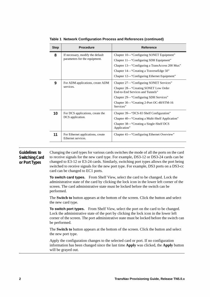
Guidelines to Switching Card or Port Types
Changing the card types for various cards switches the mode of all the ports on the card to receive signals for the new card type. For example, DS3-12 or DS3-24 cards can be changed to E3-12 or E3-24 cards. Similarly, switching port types allows the port being switched to receive signals for the new port type. For example, DS3 ports on a DS3-cc card can be changed to EC1 ports.
To switch card types. From Shelf View, select the card to be changed. Lock the administrative state of the card by clicking the lock icon in the lower left corner of the screen. The card administrative state must be locked before the switch can be performed.
The Switch to button appears at the bottom of the screen. Click the button and select the new card type.
To switch port types. From Shelf View, select the port on the card to be changed. Lock the administrative state of the port by clicking the lock icon in the lower left corner of the screen. The port administrative state must be locked before the switch can be performed.
The Switch to button appears at the bottom of the screen. Click the button and select the new port type.
Apply the configuration changes to the selected card or port. If no configuration information has been changed since the last time Apply was clicked, the Apply button will be grayed out.
8 If necessary, modify the default parameters for the equipment.
Chapter 10—“Configuring SONET Equipment”
Chapter 11—“Configuring SDH Equipment”
Chapter 13—“Configuring a TransAccess 200 Mux”
Chapter 14—“Creating a TraverseEdge 50”
Chapter 12—“Configuring Ethernet Equipment”
9 For ADM applications, create ADM services.
Chapter 27—“Configuring SONET Services”
Chapter 28—“Creating SONET Low Order End-to-End Services and Tunnels”
Chapter 29—“Configuring SDH Services”
Chapter 30—“Creating 2-Port OC-48/STM-16 Services”
10 For DCS applications, create the DCS application.
Chapter 39—“DCS-IO Shelf Configuration”
Chapter 40—“Creating a Multi-Shelf Application”
Chapter 38—“Creating a Single-Shelf DCS Application”
11 For Ethernet applications, create Ethernet services.
Chapter 41—“Configuring Ethernet Overview”
Table 1 Network Configuration Process and References (continued)
Step Procedure Reference
2 TransNav Provisioning Guide, Release TN5.0.x

Chapter 2 Discover the Network
Introduction This chapter includes the following topics:• Before You Start Provisioning Your Network• Discover the Network• Configure Node Parameters
Before You Start Provisioning Your Network
Read the list of tasks to be completed in Chapter 24—“Service Provisioning Concepts,” Before You Start Creating Services before beginning to provision your network.
TransNav Provisioning Guide, Release TN5.0.x 1
Discover the Network
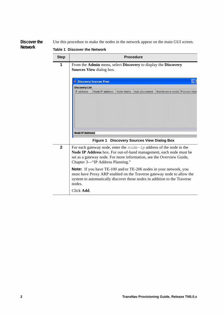
Use this procedure to make the nodes in the network appear on the main GUI screen.
Table 1 Discover the Network
Step Procedure
1 From the Admin menu, select Discovery to display the Discovery Sources View dialog box.
Figure 1 Discovery Sources View Dialog Box
2 For each gateway node, enter the node-ip address of the node in the Node IP Address box. For out-of-band management, each node must be set as a gateway node. For more information, see the Overview Guide, Chapter 3—“IP Address Planning.”
Note: If you have TE-100 and/or TE-206 nodes in your network, you must have Proxy ARP enabled on the Traverse gateway node to allow the system to automatically discover those nodes in addition to the Traverse nodes.
Click Add.
2 TransNav Provisioning Guide, Release TN5.0.x
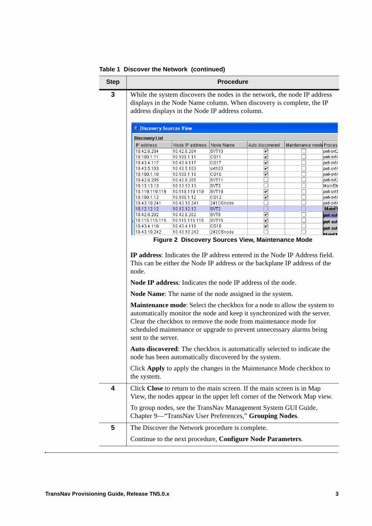
3 While the system discovers the nodes in the network, the node IP address displays in the Node Name column. When discovery is complete, the IP address displays in the Node IP address column.
Figure 2 Discovery Sources View, Maintenance Mode
IP address: Indicates the IP address entered in the Node IP Address field. This can be either the Node IP address or the backplane IP address of the node.
Node IP address: Indicates the node IP address of the node.
Node Name: The name of the node assigned in the system.
Maintenance mode: Select the checkbox for a node to allow the system to automatically monitor the node and keep it synchronized with the server. Clear the checkbox to remove the node from maintenance mode for scheduled maintenance or upgrade to prevent unnecessary alarms being sent to the server.
Auto discovered: The checkbox is automatically selected to indicate the node has been automatically discovered by the system.
Click Apply to apply the changes in the Maintenance Mode checkbox to the system.
4 Click Close to return to the main screen. If the main screen is in Map View, the nodes appear in the upper left corner of the Network Map view.
To group nodes, see the TransNav Management System GUI Guide, Chapter 9—“TransNav User Preferences,” Grouping Nodes.
5 The Discover the Network procedure is complete.
Continue to the next procedure, Configure Node Parameters.
Table 1 Discover the Network (continued)
Step Procedure
TransNav Provisioning Guide, Release TN5.0.x 3
Configure Node Parameters
After a node is commissioned, configure the following type of information at each node: node location description, alarm profiles, and NTP server IP addresses. Alarm profiles are established to customize service-affecting and non-service-affecting alarm severities for the node.
Use this procedure to configure parameters for each node.
Table 3 Configure Node Parameters
Step Procedure
1 Double-click a node to display the Shelf View.
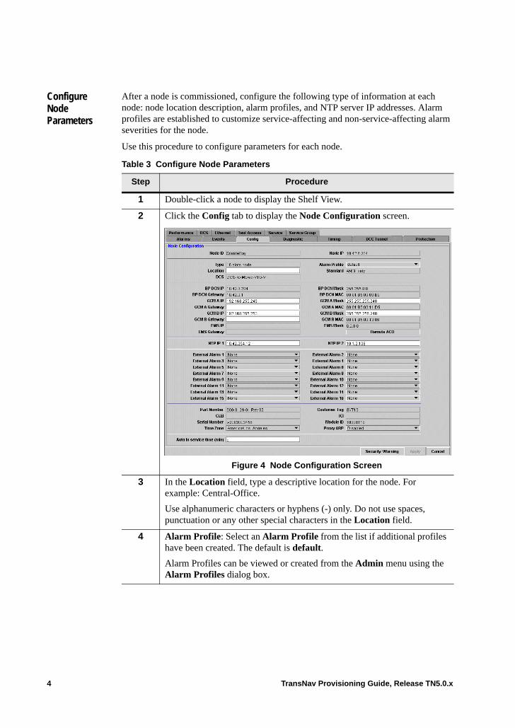
2 Click the Config tab to display the Node Configuration screen.
Figure 4 Node Configuration Screen
3 In the Location field, type a descriptive location for the node. For example: Central-Office.
Use alphanumeric characters or hyphens (-) only. Do not use spaces, punctuation or any other special characters in the Location field.
4 Alarm Profile: Select an Alarm Profile from the list if additional profiles have been created. The default is default.
Alarm Profiles can be viewed or created from the Admin menu using the Alarm Profiles dialog box.
4 TransNav Provisioning Guide, Release TN5.0.x
5 Values are displayed in the following fields. Some of these values may have been set during node commissioning using the CLI:• Node ID• Node IP• BP DCN IP• BP DCN Mask• BP DCN Gateway• GCM AIP and GCM B IP (Traverse only) • GCM A Mask and GCM B Mask (Traverse only) • GCM A Gateway and GCM B Gateway (Traverse only) • EMS IP• EMSMask• EMS Gateway
For more information, refer to:• TraverseEdge 100 User Guide, Chapter 10—“Node Start-up and Initial
Configuration”• Traverse Hardware Installation and Commissioning Guide,
Chapter 1—“Node Start-up and Commissioning.”
6 You can enter values for the NTP IP 1 and NTP IP 2 fields if they were not set during the initial start-up procedures. The Network Time Protocol (NTP) server IP address is used by the node to derive the Time of Day that is used for performance monitoring, alarm, and event logging.
NTP IP 1Type: the IP address of the primary NTP server. (For example: aaa.bbb.ccc.ddd)
NTP IP 2Type: the IP address of the secondary NTP server. (For example: aaa.bbb.ccc.ddd)
Force10 recommends using the primary TransNav server as the primary NTP source if you do not already have a NTP source defined. Refer to the Software Installation Guide, Chapter 1—“Creating the Management Servers” for information on how to activate the NTP server on the management server.
7 External Alarm: These fields display a default value of UNKWN. Select one of the External Alarm input alarm types (based on the environmental alarms input cabling completed during node installation).
There are 4 external alarms available for TE-100 nodes and 16 external alarms available on Traverse nodes.
Table 3 Configure Node Parameters (continued)
Step Procedure
TransNav Provisioning Guide, Release TN5.0.x 5
8 Proxy ARP: Enable this parameter if this node is to be used as the proxy server for the IP subnet.
Note: Proxy ARP can only be enabled on Traverse nodes.
See the Planning and Engineering Guide, Chapter 7—“IP Address Planning,” Proxy ARP for a complete description of Proxy ARP.
9 Auto in service time (min) (Traverse only): Set the amount of time, in minutes, to allow service affecting alarms to be reported. If no port-level or service-level service affecting alarms are reported within the set time, the port or service set up with automatic in service will be unlocked allowing alarms to be reported. Valid values are 0 to 99 hours in one-minute increments. The default value is 30 minutes.
10 Click Apply.
11 Repeat Steps 1 through 10 for each node.
12 The Configure Node Parameters procedure is complete.
Table 3 Configure Node Parameters (continued)
Step Procedure
6 TransNav Provisioning Guide, Release TN5.0.x

Chapter 3 Configure Network Timing
Introduction Configure the timing source for each node in a server domain. For each node, you can configure either external timing or line timing from OCor STM interfaces.
Typically, one node in the central office receives redundant timing signals from an external source. This node becomes the primary timing source for the network. The other nodes receive the timing reference from optical interfaces. The primary reference is the shortest route to the primary timing source.
Synchronized primary and secondary timing inputs from the external timing source are connected at the main backplane and bridged to the shelf’s system control cards.This chapter describes the following information:• Global Timing Options• External Timing• Line Timing• Derived Timing• Protection Switching External Timing References• Protection Switching Line Timing References
Use the following procedures to configure timing options:• Before You Configure Timing• Network Timing Examples• Configure Global Timing Options• Configure External Timing• Configure Line Timing• Configure Derived References
Daylight Saving Time. As part of a United States federal energy conservation effort for 2007, Daylight Saving Time (DST) starts three weeks earlier and ends one week later than in previous years. Certain telecommunications products contain the ability to synchronize to a network clock or automatically change their time stamp to reflect time changes. Each device may handle the recent change in DST differently.• All dates displayed in the TransNav management system CLI for alarms, upgrade
times, events, and performance monitoring (PM) include the new DST. The TraverseEdge 100 system CLI also includes the new DST.
TransNav Provisioning Guide, Release TN5.0.x 1
Pinouts. For information on pinouts for each timing interface, instructions on how to connect timing inputs from the central office external timing source, and how to connect timing outputs from a node to the external clock, see the Traverse Installation and Commissioning Guide.
Global Timing Options
Configure global timing options at each node in the domain.
The Timing tab allows you to view and set the following information:• Standard: Displays the timing standard for the shelf: This value is set during node
commissioning through the CLI (exec node commission standard).• Timing Mode: Select to receive timing from an external source or from a line source
(OC or STM interface).• Quality of RES (available if Standard is ANSI): Assigns a quality level for the RES
message. Revertive: Select for revertive timing. Clear for non-revertive timing. In revertive timing, if the timing signal is lost from the highest priority timing source, the signal is received from the second priority timing source. If the highest priority timing source then becomes available, revertive timing switches back to the highest priority timing source. In non-revertive timing, timing does not switch back to the highest priority timing source when it becomes available.
• External Out Enable: Enables or disable derived references. Derived timing is the process of providing a timing reference from a line interface and sending it to an external clock.
• Ignore SSMR: Ignore the synchronization status message received. • Clock Mode: Displays the state of the timing sub-system.• Holdover Quality: Displays the clock quality (Stratum 3) of the local oscillator on
the GCM cards. • WTR Time: Time, in minutes, that the system will wait before considering the
primary timing source as valid again. This time ensures that a previously failed synchronization source is fault-free before it is considered available.
For the procedure to configure the global timing options, see Configure Global Timing Options
2 TransNav Provisioning Guide, Release TN5.0.x
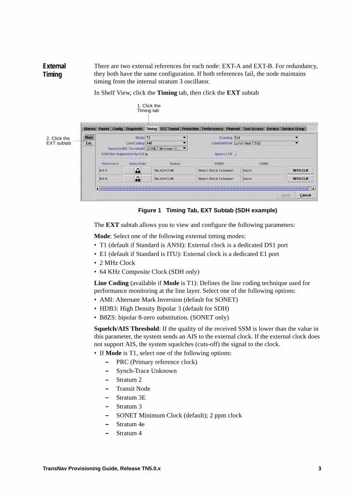
External Timing
There are two external references for each node: EXT-A and EXT-B. For redundancy, they both have the same configuration. If both references fail, the node maintains timing from the internal stratum 3 oscillator.
In Shelf View, click the Timing tab, then click the EXT subtab.
Figure 1 Timing Tab, EXT Subtab (SDH example)
The EXT subtab allows you to view and configure the following parameters:
Mode: Select one of the following external timing modes:• T1 (default if Standard is ANSI): External clock is a dedicated DS1 port• E1 (default if Standard is ITU): External clock is a dedicated E1 port • 2 MHz Clock• 64 KHz Composite Clock (SDH only)
Line Coding (available if Mode is T1): Defines the line coding technique used for performance monitoring at the line layer. Select one of the following options:• AMI: Alternate Mark Inversion (default for SONET)• HDB3: High Density Bipolar 3 (default for SDH)• B8ZS: bipolar 8-zero substitution. (SONET only)
Squelch/AIS Threshold: If the quality of the received SSM is lower than the value in this parameter, the system sends an AIS to the external clock. If the external clock does not support AIS, the system squelches (cuts-off) the signal to the clock.• If Mode is T1, select one of the following options:
– PRC (Primary reference clock)– Synch-Trace Unknown– Stratum 2– Transit Node– Stratum 3E– Stratum 3– SONET Minimum Clock (default); 2 ppm clock– Stratum 4e– Stratum 4
1. Click the Timing tab
2. Click the EXT subtab
TransNav Provisioning Guide, Release TN5.0.x 3
– Don’t use for sync• If Mode is E1, select one of the following options:
– SSUA (Synchronization supply unit type A): Transit– SSUB (SSU type B): Local– SEC (SDH equipment clock)– DUS (Do not use for synchronization)
Note: Legacy networks that don’t support SSM are considered DUS.– Don’t use for sync
SSM Not Supported by ESF (if Framing is ESF): Check the box if the synchronize status message is not supported by the ESF framing format.
Framing: The framing format used by the external clock. • If Mode is T1, select one of the following values:
– Esf (Extended super frame) (default)– Sf (Superframe)
• If Mode is E1, select one of the following values for SDH:– Basic Frame (default): The timing interface detects and generates the Basic
frame format per ITU-T Rec G.704/2.3 and G.706/4.1.2. This format does not support the SSM.
– Multi-Frame: The timing interface detects and generates CRC-4 Multi-frame format per ITU-T Rec G.706/4.2. This format supports the SSM.
LineBuildOut: Line build out is based on the attenuation required for the circuit.• If Mode is T1, select one of the following:
– Long Haul 0dB– Long Haul 7.5dB– Long Haul 15dB– Long Haul 22.5dB– Long Haul Tr62411 0dB– Short Haul 110ft (default)– Short Haul 220ft– Short Haul 330ft– Short Haul 440ft– Short Haul 550ft– Short Haul 660ft– Short Haul Tr62411 110ft– Short Haul Tr62411 220ft– Short Haul Tr62411 330ft– Short Haul Tr62411 440ft– Short Haul Tr62411 550ft– Short Haul Tr62411 660ft
• Read only if Mode is T1: 120 Ohm for SDH
Ignore LOF (available if Mode is T1): Select (default) to ignore LOF (Loss of Frame) alarms. Clear to receive LOF alarms.
4 TransNav Provisioning Guide, Release TN5.0.x
SSM Sa Bit (available if Mode is E1) select one of the following for SDH:• BIT_SA4 (default)• BIT_SA5• BIT_SA6• BIT_SA7• BIT_SA8
EXT-A Assigned SSMR, EXT-B Assigned SSMR: If the external clock does not support SSM and you want to operate using a received SSM, select the SSM quality for the EXT-A Assigned SSMR, and EXT-B Assigned SSMR parameters.• PRC (Primary reference clock)• SSUA (Synchronization supply unit type A): Transit• SSUB (SSU type B): Local• SEC (SDH equipment clock)• DUS (Do not use for synchronization)
Note: Networks that don’t support SSM are considered DUS.• Auto (default for SDH)
Reference: External references are listed as Ext-A and Ext-B.
Adm. State: Click the lock icon to change the administrative state of the timing source:• Timing signal is unlocked and available for use. When Apply is clicked, the
operational state is enabled.• Timing signal is locked and unavailable for use (default). When Apply is clicked, the
operational state is disabled.
Status: Indicates status of external reference signal: Valid, OOB (Out of Band), or NOACT (Not active/Out of Band).
SSMR: Displays synchronization status messages received by this external reference.
SSMT: Displays synchronization status messages transmitted by this external reference.
WTR CLR: Click this button so the system immediately considers a source as a valid source (instead of waiting for the time specified in the WTR Time parameter).
Command buttons are as follows:• Apply: Apply timing source information. After timing source information is applied,
button turns gray.• Cancel: Do not apply timing source information.
TransNav Provisioning Guide, Release TN5.0.x 5
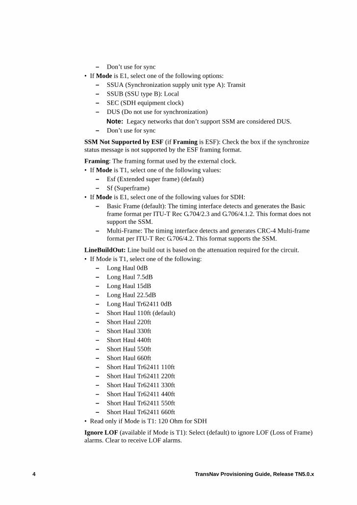
Line Timing You can establish up to four line timing sources based on your network requirements and the number of OCand STM interfaces in the node. You first select the references (up to four per node), then you assign a priority to each one.
The node uses the priority 1 reference unless there is a failure on that reference. If there is a failure, the node switches to the next priority. If all of the references fail, the node maintains timing from the internal stratum 3 oscillator.
You can configure line timing sources and perform switch commands on the Timing tab. .
Figure 2 Timing Tab—Line Timing
The timing screen dynamically changes when you select Line Time in the Timing Mode parameter.• Line Facility Data explains the information in the Line Facility area.• Reference List Options explains the information the Reference List area.
Important: For Traverse nodes, line timing sources can be configured from OC-N/STM-N ports only and using one port per card. Each OC-N card can provide a single line timing source from any of its available ports.
Line Time Mode
Line Facility Data
Reference List Options
Check mark indicates active reference
6 TransNav Provisioning Guide, Release TN5.0.x

Line Facility Data
The Line Facility area on the Timing screen allows you to view or configure the following information:
Reference: You can provision up to four line timing references per node depending on your network requirements and number of OC interfaces per node. Labels sources as Reference 1, Reference 2, Reference 3, and Reference 4.
Source: Select from the list of available ports (SONET or STM interfaces only).
Status (read only): Indicates status of timing signal. Displays one of the following states:• Valid. Valid source and system can use this reference.• OOB. Out-of-Band alarm. The frequency is not within expected range.• NOACT. No activity alarm. The system cannot detect a signal.• PLL. Phase lock alarm. The system cannot lock to this reference.
SSMR (read only): Synchronization status messages received by this interface. Displays one of the following messages:• PRC. Primary reference clock.• SSUA. (SDH only) Synchronization supply unit type A. Transit• SSUB. (SDH only) Synchronization supply unit type B. Local. • SEC. SDH equipment clock. (SDH only) • DUS: (SDH only) Do not use for synchronization. Legacy networks that don’t
support SSM are considered DUS.• Signal Fail Present.• None.
SSMT (read only): Synchronization status messages transmitted by this interface. Displays one of the following messages:• PRC. Primary reference clock.• SSUA. (SDH only) Synchronization supply unit type A. Transit• SSUB. (SDH only) Synchronization supply unit type B. Local. • SEC. (SDH only) SDH equipment clock. • DUS. (SDH only) Do not use for synchronization. Legacy networks that don’t
support SSM are considered DUS.• Signal Fail Present.• None.
WTR CLR (command button). Click this button so the system immediately starts to qualify a source as a valid source (instead of waiting for the time specified in WTR Time parameter).
TransNav Provisioning Guide, Release TN5.0.x 7
Reference List Options
The Reference List area on the Timing screen allows you to view and configure the following information:
Priority 1, Priority 2, Priority 3, Priority 4: Select the line timing priority for this interface from one of the following options:• no_reference—default• Reference 1—highest priority• Reference 2• Reference 3• Reference 4—lowest priority
Ext. Command: Displays any commands performed on line timing signal. See Protection Switching Line Timing References.
The check box beside the Ext. Command column indicates the active reference.
Command buttons are as follows:• Apply: Apply timing source information. After timing source information is applied,
button turns gray.• Cancel: Do not apply timing source information.
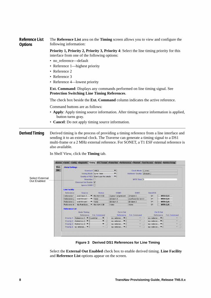
Derived Timing Derived timing is the process of providing a timing reference from a line interface and sending it to an external clock. The Traverse can generate a timing signal to a DS1 multi-frame or a 2 MHz external reference. For SONET, a T1 ESF external reference is also available.
In Shelf View, click the Timing tab.
Figure 3 Derived DS1 References for Line Timing
Select the External Out Enabled check box to enable derived timing. Line Facility and Reference List options appear on the screen.
Select External Out Enabled
8 TransNav Provisioning Guide, Release TN5.0.x
Under Line Facility, select up to four OC interfaces as timing references. The port needs to be enabled (unlocked administrative state). See Line Facility Data for details on this area.
Under Reference List, select the priority for each line reference, then select a reference in order of priority to generate a signal to EXT-A and EXT-B:• no_reference (default): reference is not used.• Reference 1 (highest).• Reference 2.• Reference 3.• Reference 4 (lowest).
Ext. Command: Displays any commands performed on the references. See Protection Switching Line Timing References.
Protection Switching External Timing References
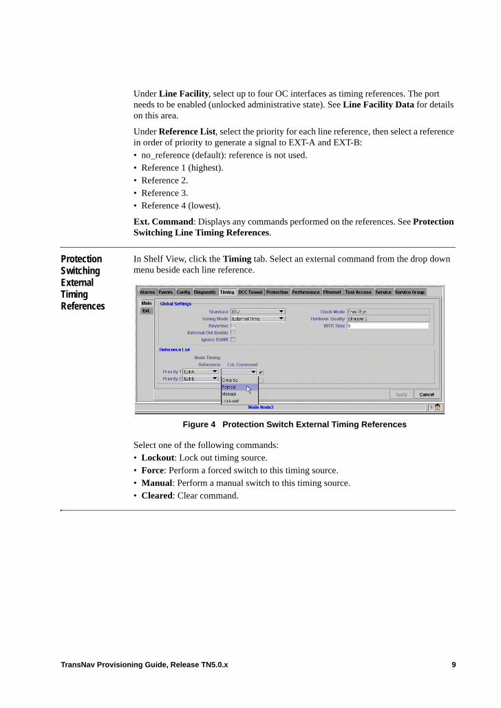
In Shelf View, click the Timing tab. Select an external command from the drop down menu beside each line reference.
Figure 4 Protection Switch External Timing References
Select one of the following commands:• Lockout: Lock out timing source.• Force: Perform a forced switch to this timing source.• Manual: Perform a manual switch to this timing source.• Cleared: Clear command.
TransNav Provisioning Guide, Release TN5.0.x 9
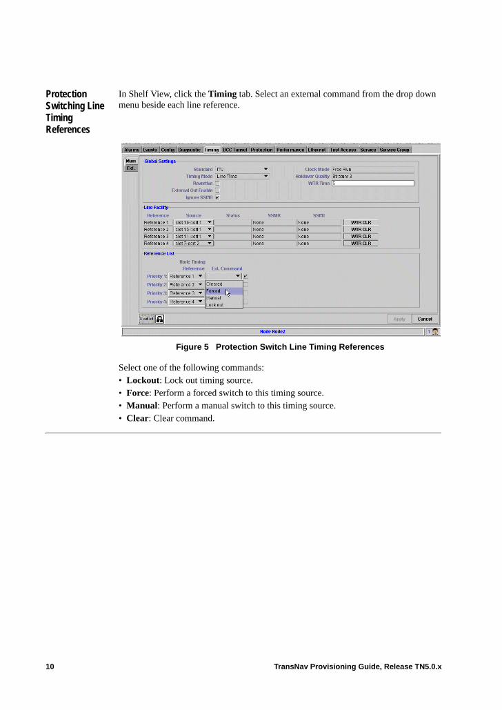
Protection Switching Line Timing References
In Shelf View, click the Timing tab. Select an external command from the drop down menu beside each line reference.
Figure 5 Protection Switch Line Timing References
Select one of the following commands:• Lockout: Lock out timing source.• Force: Perform a forced switch to this timing source.• Manual: Perform a manual switch to this timing source.• Clear: Clear command.
10 TransNav Provisioning Guide, Release TN5.0.x
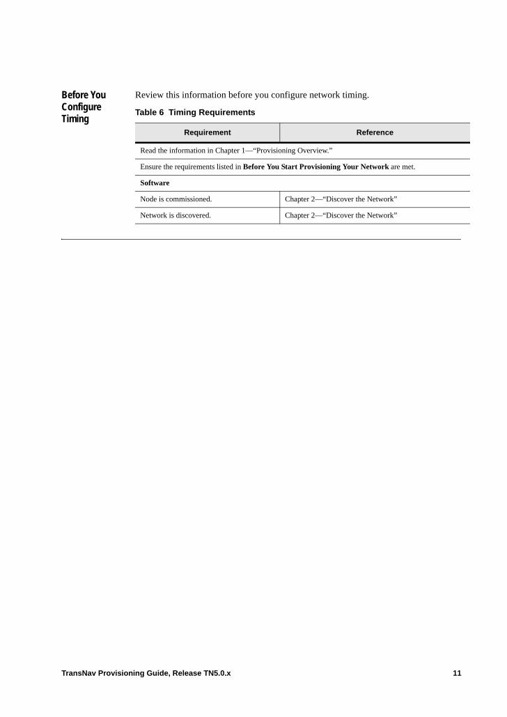
Before You Configure Timing
Review this information before you configure network timing.
Table 6 Timing Requirements
Requirement Reference
Read the information in Chapter 1—“Provisioning Overview.”
Ensure the requirements listed in Before You Start Provisioning Your Network are met.
Software
Node is commissioned. Chapter 2—“Discover the Network”
Network is discovered. Chapter 2—“Discover the Network”
TransNav Provisioning Guide, Release TN5.0.x 11
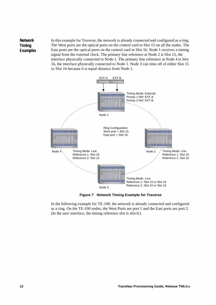
Network Timing Examples
In this example for Traverse, the network is already connected and configured as a ring. The West ports are the optical ports on the control card in Slot 15 on all the nodes. The East ports are the optical ports on the control card in Slot 16. Node 1 receives a timing signal from the external clock. The primary line reference at Node 2 is Slot 15, the interface physically connected to Node 1. The primary line reference at Node 4 is Slot 16, the interface physically connected to Node 1. Node 3 can time off of either Slot 15 or Slot 16 because it is equal distance from Node 1.
Figure 7 Network Timing Example for Traverse
In the following example for TE-100, the network is already connected and configured as a ring. On the TE-100 nodes, the West Ports are port 1 and the East ports are port 2. (In the user interface, the timing reference slot is slot-0.)
Node 2Node 4
Node 1
EXT-A EXT-B
Node 3
Ring ConfigurationWest port = Slot 15East port = Slot 16
Timing Mode: ExternalPriority 1 Ref: EXT-APriority 2 Ref: EXT-B
Timing Mode: LineReference 1: Slot 16Reference 2: Slot 15
Timing Mode: LineReference 1: Slot 15Reference 2: Slot 16
Timing Mode: LineReference 1: Slot 15 or Slot 16Reference 2: Slot 15 or Slot 16
12 TransNav Provisioning Guide, Release TN5.0.x
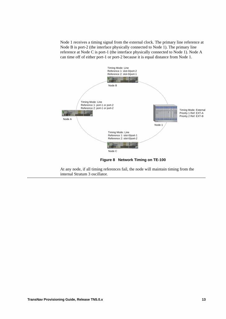
Node 1 receives a timing signal from the external clock. The primary line reference at Node B is port-2 (the interface physically connected to Node 1). The primary line reference at Node C is port-1 (the interface physically connected to Node 1). Node A can time off of either port-1 or port-2 because it is equal distance from Node 1.
Figure 8 Network Timing on TE-100
At any node, if all timing references fail, the node will maintain timing from the internal Stratum 3 oscillator.
Node 1
Timing Mode: ExternalPriority 1 Ref: EXT-APriority 2 Ref: EXT-B
Timing Mode: LineReference 1: slot-0/port-2Reference 2: slot-0/port-1
Timing Mode: LineReference 1: port-1 or port-2Reference 2: port-1 or port-2
Node B
Node C
Node A
Timing Mode: LineReference 1: slot-0/port-1Reference 2: slot-0/port-2
TransNav Provisioning Guide, Release TN5.0.x 13

Guidelines to Configuring Network Timing
Use the following guidelines to configure timing in a Traverse network.• If an external clock is present, always configure external timing for the node. • Configure line timing in such a way that the primary reference is the shortest route to
the primary timing source.• For derived timing, the Traverse can generate a timing signal to a DS1or E1
multi-frame, a T1 ESF, a 2 MHz external reference, or a 64 KHz composite clock.
For information on pinouts for each timing interface, instructions on connecting timing inputs from the central office external timing source, and instruction on connecting timing outputs from a node to the external clock, see the following documents:• For Traverse, see the Traverse Cabling and Cabling Specifications Guide,
Chapter 18—“Traverse Timing Interface Cabling”• For TE-100, see the TraverseEdge 100 User Guide, Chapter 18—“Timing Interface
Cabling”
Configure Global Timing Options
Configure the timing options at each node in the domain. Use this procedure to configure the global settings for system timing.
Table 9 Configure Global Timing Options
Step Procedure
1 In Shelf View, click the Timing tab to display the Main timing screen (Main subtab).
Figure 10 Shelf View, Timing Tab, Main Subtab
2 From the Standard list, select the timing standard to be used for the shelf:• Select ANSI for North American operation.• Select ITU (default) for operations outside of North America.
3 From Timing Mode list:• Select External to receive timing from an external reference.• Select Line to derive timing from an OC or STM interface.
4 Select the Revertive checkbox to revert back to a primary reference source after the conditions that caused a protection switch to a secondary timing reference are corrected.
14 TransNav Provisioning Guide, Release TN5.0.x

Configure External Timing
There are two external references for each node: EXT-A and EXT-B. For redundancy, they both have the same configuration. If both references fail, the node maintains timing from the internal Stratum 3 oscillator. Use this procedure to configure external timing interfaces for a node.
5 In the WTR Time field, set a time in minutes that the system will wait before considering the primary timing source as valid again. Enter a value between 1 and 12.
Enter 0 to disable this function.
6 By default, the Ignore SSMR (synchronization status message received) parameter is selected. That is, the node will use provisioned priorities to select the best timing reference.
Clear the checkbox to use the SSM level to prioritize timing references.
7 Click Apply to save the timing configuration settings.
8 The Configure Global Timing Options procedure is complete.
If the Timing Mode is External, continue to Configure External Timing
If the Timing Mode is Line, continue to Configure Line Timing
Table 9 Configure Global Timing Options (continued)
Step Procedure
Table 11 Configure External Timing
Step Procedure
1 Complete the procedure Configure Global Timing Options.
2 In Shelf View, click the Timing tab, then click the EXT subtab.
Figure 12 Shelf View, Timing tab, EXT Subtab
3 From the Mode list: • Select DS1 if the external clock is a dedicated DS1 port. Go to Step 4.
• Select 2 MHz Clock. Go to Step 5.• Select 64 KHz Composite Clock. Go to Step 5.
TransNav Provisioning Guide, Release TN5.0.x 15
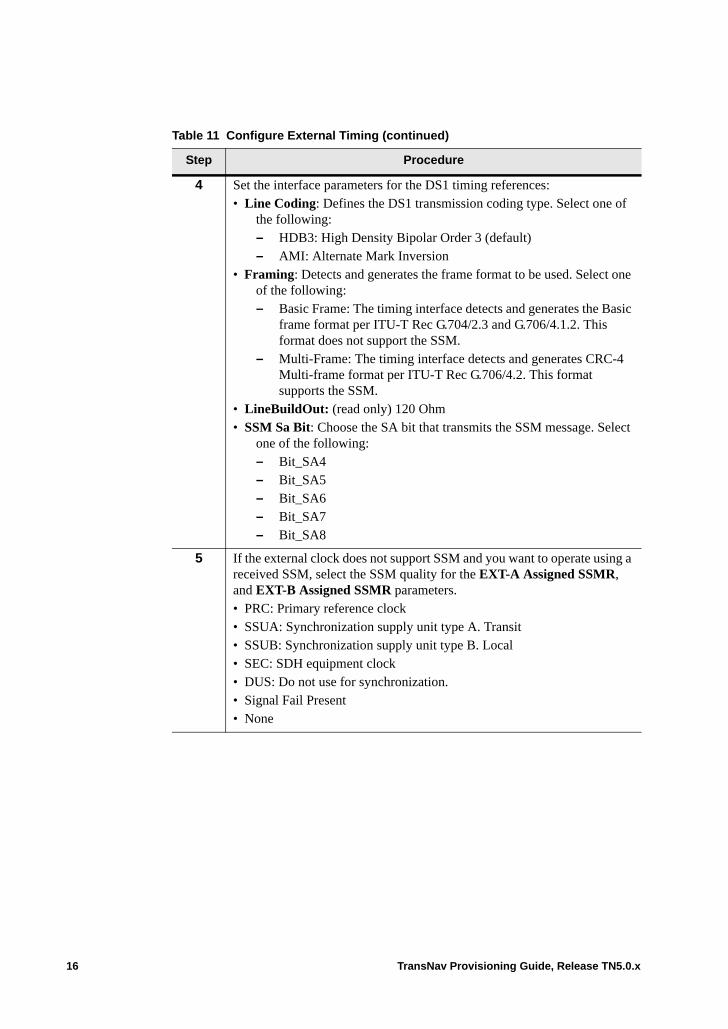
4 Set the interface parameters for the DS1 timing references:• Line Coding: Defines the DS1 transmission coding type. Select one of
the following:– HDB3: High Density Bipolar Order 3 (default)– AMI: Alternate Mark Inversion
• Framing: Detects and generates the frame format to be used. Select one of the following:– Basic Frame: The timing interface detects and generates the Basic
frame format per ITU-T Rec G.704/2.3 and G.706/4.1.2. This format does not support the SSM.
– Multi-Frame: The timing interface detects and generates CRC-4 Multi-frame format per ITU-T Rec G.706/4.2. This format supports the SSM.
• LineBuildOut: (read only) 120 Ohm• SSM Sa Bit: Choose the SA bit that transmits the SSM message. Select
one of the following: – Bit_SA4 – Bit_SA5 – Bit_SA6 – Bit_SA7 – Bit_SA8
5 If the external clock does not support SSM and you want to operate using a received SSM, select the SSM quality for the EXT-A Assigned SSMR, and EXT-B Assigned SSMR parameters.• PRC: Primary reference clock• SSUA: Synchronization supply unit type A. Transit• SSUB: Synchronization supply unit type B. Local• SEC: SDH equipment clock• DUS: Do not use for synchronization. • Signal Fail Present• None
Table 11 Configure External Timing (continued)
Step Procedure
16 TransNav Provisioning Guide, Release TN5.0.x

6 For each reference, unlock the administrative state to enable the external timing. Click the Lock icon in the Adm State column next to each reference to unlock the administrative state.
Figure 13 Timing Tab, EXT Subtab
7 Click Apply to save the external interface settings.
8 Click the Main subtab to return to the Main timing screen.
Figure 14 Timing Tab, Main Subtab, Reference Priority
9 Select Priority 1 and Priority 2 external timing references.
A checkmark indicates the active reference.
10 Click Apply to save the reference list settings.
11 The Configure External Timing procedure is complete.
Table 11 Configure External Timing (continued)
Step Procedure
TransNav Provisioning Guide, Release TN5.0.x 17

Configure Line Timing
You can establish up to four line timing sources based on your network requirements and the number of OCand STM interfaces in the node. You first select the references (up to four per node), then you assign a priority to each one.
The node uses the priority 1 reference unless there is a failure on that reference. If there is a failure, the node switches to the next priority. If all of the references fail, the node maintains timing from the internal stratum 3 oscillator.
You can configure line timing sources and perform switch commands on the Timing tab.
For Traverse, line timing sources can be configured from OC-N/STM-N ports only and using one port per card
Use this procedure to configure line timing from an OC or STM interface for a node.
Important: Each OC-N card can provide a single line timing source from any of its available ports.
Table 15 Configure Line Timing
Step Procedure
1 Complete the procedure Configure Global Timing Options.
2 When configuring the Global Timing option, you selected Line Time in Timing Mode. The Line Facility and Reference List options display on the Timing screen.
Figure 16 Line Timing, Timing Tab, Main Subtab
3 For each line reference, select a port for the timing reference. The port needs to be enabled (in an unlocked administrative state).
4 Select a priority for each reference. If there is a failure on the first reference, the node switches to the next reference.
A checkmark indicates the active reference.
18 TransNav Provisioning Guide, Release TN5.0.x
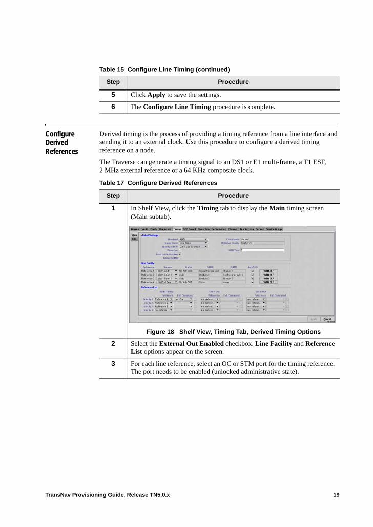
Configure Derived References
Derived timing is the process of providing a timing reference from a line interface and sending it to an external clock. Use this procedure to configure a derived timing reference on a node.
The Traverse can generate a timing signal to an DS1 or E1 multi-frame, a T1 ESF, 2 MHz external reference or a 64 KHz composite clock.
5 Click Apply to save the settings.
6 The Configure Line Timing procedure is complete.
Table 15 Configure Line Timing (continued)
Step Procedure
Table 17 Configure Derived References
Step Procedure
1 In Shelf View, click the Timing tab to display the Main timing screen (Main subtab).
Figure 18 Shelf View, Timing Tab, Derived Timing Options
2 Select the External Out Enabled checkbox. Line Facility and Reference List options appear on the screen.
3 For each line reference, select an OC or STM port for the timing reference. The port needs to be enabled (unlocked administrative state).
TransNav Provisioning Guide, Release TN5.0.x 19
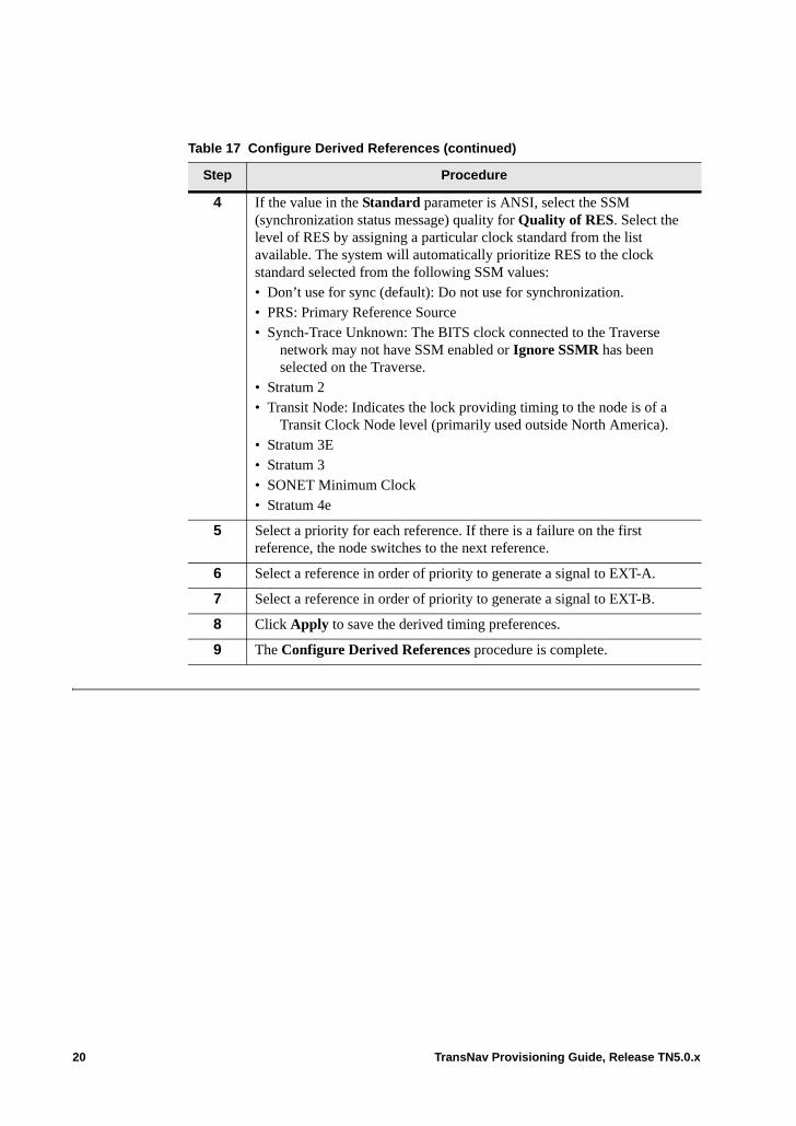
4 If the value in the Standard parameter is ANSI, select the SSM (synchronization status message) quality for Quality of RES. Select the level of RES by assigning a particular clock standard from the list available. The system will automatically prioritize RES to the clock standard selected from the following SSM values:• Don’t use for sync (default): Do not use for synchronization. • PRS: Primary Reference Source• Synch-Trace Unknown: The BITS clock connected to the Traverse
network may not have SSM enabled or Ignore SSMR has been selected on the Traverse.
• Stratum 2 • Transit Node: Indicates the lock providing timing to the node is of a
Transit Clock Node level (primarily used outside North America). • Stratum 3E • Stratum 3 • SONET Minimum Clock • Stratum 4e
5 Select a priority for each reference. If there is a failure on the first reference, the node switches to the next reference.
6 Select a reference in order of priority to generate a signal to EXT-A.
7 Select a reference in order of priority to generate a signal to EXT-B.
8 Click Apply to save the derived timing preferences.
9 The Configure Derived References procedure is complete.
Table 17 Configure Derived References (continued)
Step Procedure
20 TransNav Provisioning Guide, Release TN5.0.x
Chapter 4 Creating DCC Tunnels
Introduction The data communications channel (DCC) carries operations, administration, maintenance, and provisioning information between nodes in a network. You can use the section DCC of any SONET or STM interface to connect third-party equipment transparently over a network of Traverse nodes. Tunnel a third-party DCC through the network using the section DCC bytes of the associated optical interface.
This chapter contains the following information.• DCC Tunnel Example• Before You Tunnel a DCC• Disable Control Data Procedure• Tunneling a DCC Through a Traverse Network
This chapter also describes the following parameters needed to configure DCC tunnels: • DCC Tunnel Tab
TransNav Provisioning Guide, Release TN5.0.x 1
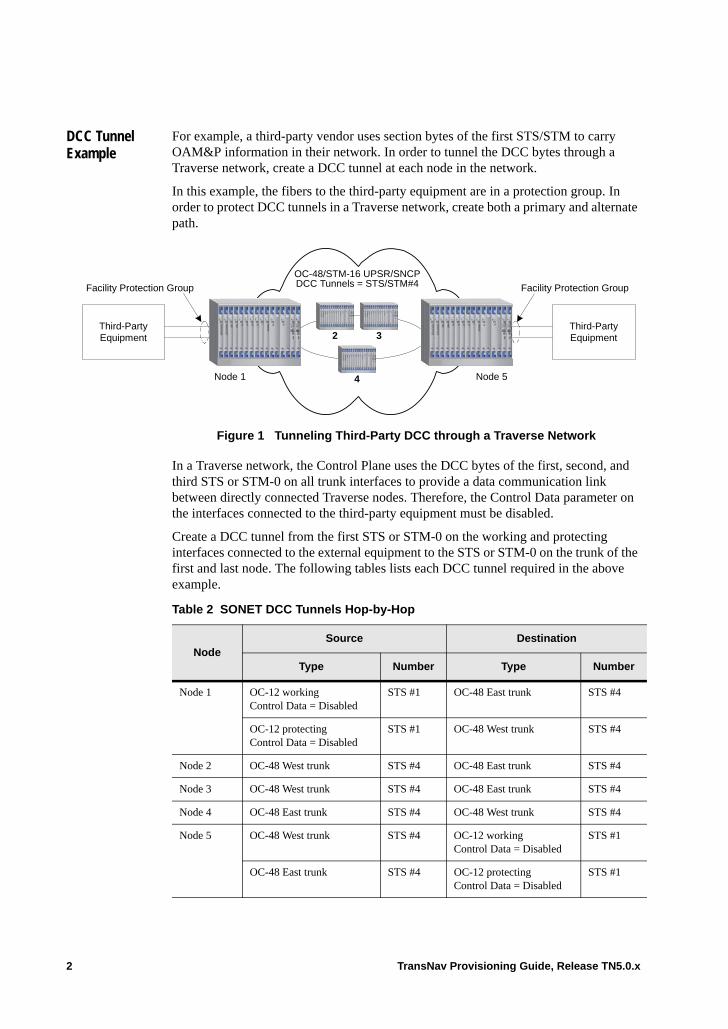
DCC Tunnel Example
For example, a third-party vendor uses section bytes of the first STS/STM to carry OAM&P information in their network. In order to tunnel the DCC bytes through a Traverse network, create a DCC tunnel at each node in the network.
In this example, the fibers to the third-party equipment are in a protection group. In order to protect DCC tunnels in a Traverse network, create both a primary and alternate path.
Figure 1 Tunneling Third-Party DCC through a Traverse Network
In a Traverse network, the Control Plane uses the DCC bytes of the first, second, and third STS or STM-0 on all trunk interfaces to provide a data communication link between directly connected Traverse nodes. Therefore, the Control Data parameter on the interfaces connected to the third-party equipment must be disabled.
Create a DCC tunnel from the first STS or STM-0 on the working and protecting interfaces connected to the external equipment to the STS or STM-0 on the trunk of the first and last node. The following tables lists each DCC tunnel required in the above example.
Third-PartyEquipment
Node 1 Node 5
2 3
4
Third-PartyEquipment
Facility Protection Group Facility Protection Group
OC-48/STM-16 UPSR/SNCPDCC Tunnels = STS/STM#4
Table 2 SONET DCC Tunnels Hop-by-Hop
NodeSource Destination
Type Number Type Number
Node 1 OC-12 workingControl Data = Disabled
STS #1 OC-48 East trunk STS #4
OC-12 protectingControl Data = Disabled
STS #1 OC-48 West trunk STS #4
Node 2 OC-48 West trunk STS #4 OC-48 East trunk STS #4
Node 3 OC-48 West trunk STS #4 OC-48 East trunk STS #4
Node 4 OC-48 East trunk STS #4 OC-48 West trunk STS #4
Node 5 OC-48 West trunk STS #4 OC-12 workingControl Data = Disabled
STS #1
OC-48 East trunk STS #4 OC-12 protectingControl Data = Disabled
STS #1
2 TransNav Provisioning Guide, Release TN5.0.x
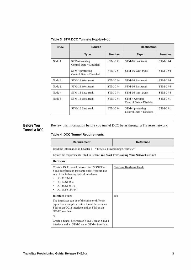
Before You Tunnel a DCC
Review this information before you tunnel DCC bytes through a Traverse network.
Table 3 STM DCC Tunnels Hop-by-Hop
Node Source Destination
Type Number Type Number
Node 1 STM-4 workingControl Data = Disabled
STM-0 #1 STM-16 East trunk STM-0 #4
STM-4 protectingControl Data = Disabled
STM-0 #1 STM-16 West trunk STM-0 #4
Node 2 STM-16 West trunk STM-0 #4 STM-16 East trunk STM-0 #4
Node 3 STM-16 West trunk STM-0 #4 STM-16 East trunk STM-0 #4
Node 4 STM-16 East trunk STM-0 #4 STM-16 West trunk STM-0 #4
Node 5 STM-16 West trunk STM-0 #4 STM-4 workingControl Data = Disabled
STM-0 #1
STM-16 East trunk STM-0 #4 STM-4 protectingControl Data = Disabled
STM-0 #1
Table 4 DCC Tunnel Requirements
Requirement Reference
Read the information in Chapter 1—“TN5.0.x Provisioning Overview”
Ensure the requirements listed in Before You Start Provisioning Your Network are met.
Hardware
Create a DCC tunnel between two SONET or STM interfaces on the same node. You can use any of the following optical interfaces:• OC-3/STM-1 • OC-12/STM-4• OC-48/STM-16• OC-192/STM-64
Traverse Hardware Guide
Interface Types
The interfaces can be of the same or different types. For example, create a tunnel between an STS on an OC-3 interface and an STS on an OC-12 interface.
or
Create a tunnel between an STM-0 on an STM-1 interface and an STM-0 on an STM-4 interface.
n/a
TransNav Provisioning Guide, Release TN5.0.x 3
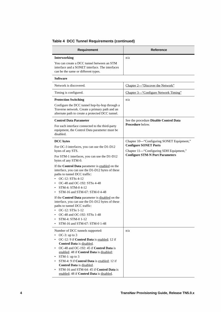
Interworking
You can create a DCC tunnel between an STM interface and a SONET interface. The interfaces can be the same or different types.
n/a
Software
Network is discovered. Chapter 2—“Discover the Network”
Timing is configured. Chapter 3—“Configure Network Timing”
Protection Switching
Configure the DCC tunnel hop-by-hop through a Traverse network. Create a primary path and an alternate path to create a protected DCC tunnel.
n/a
Control Data Parameter
For each interface connected to the third-party equipment, the Control Data parameter must be disabled.
See the procedure Disable Control Data Procedure below.
DCC bytes
For OC-3 interfaces, you can use the D1-D12 bytes of any STS.
For STM-1 interfaces, you can use the D1-D12 bytes of any STM-0.
If the Control Data parameter is enabled on the interface, you can use the D1-D12 bytes of these paths to tunnel DCC traffic:• OC-12: STSs 4-12 • OC-48 and OC-192: STSs 4-48• STM-4: STM-0 4-12• STM-16 and STM-67: STM-0 4-48
If the Control Data parameter is disabled on the interface, you can use the D1-D12 bytes of these paths to tunnel DCC traffic:• OC-12: STSs 1-12• OC-48 and OC-192: STSs 1-48• STM-4: STM-0 1-12• STM-16 and STM-67: STM-0 1-48
Chapter 10—“Configuring SONET Equipment,” Configure SONET Ports
Chapter 11—“Configuring SDH Equipment,” Configure STM-N Port Parameters
Number of DCC tunnels supported: • OC-3: up to 3• OC-12: 9 if Control Data is enabled; 12 if
Control Data is disabled.• OC-48 and OC-192: 45 if Control Data is
enabled. 48 if Control Data is disabled;• STM-1: up to 3• STM-4: 9 if Control Data is enabled; 12 if
Control Data is disabled.• STM-16 and STM-64: 45 if Control Data is
enabled; 48 if Control Data is disabled.
n/a
Table 4 DCC Tunnel Requirements (continued)
Requirement Reference
4 TransNav Provisioning Guide, Release TN5.0.x
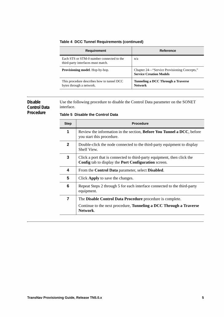
Disable Control Data Procedure
Use the following procedure to disable the Control Data parameter on the SONET interface.
Each STS or STM-0 number connected to the third-party interfaces must match.
n/a
Provisioning model. Hop-by-hop. Chapter 24—“Service Provisioning Concepts,” Service Creation Models
This procedure describes how to tunnel DCC bytes through a network.
Tunneling a DCC Through a Traverse Network
Table 4 DCC Tunnel Requirements (continued)
Requirement Reference
Table 5 Disable the Control Data
Step Procedure
1 Review the information in the section, Before You Tunnel a DCC, before you start this procedure.
2 Double-click the node connected to the third-party equipment to display Shelf View.
3 Click a port that is connected to third-party equipment, then click the Config tab to display the Port Configuration screen.
4 From the Control Data parameter, select Disabled.
5 Click Apply to save the changes.
6 Repeat Steps 2 through 5 for each interface connected to the third-party equipment.
7 The Disable Control Data Procedure procedure is complete.
Continue to the next procedure, Tunneling a DCC Through a Traverse Network.
TransNav Provisioning Guide, Release TN5.0.x 5
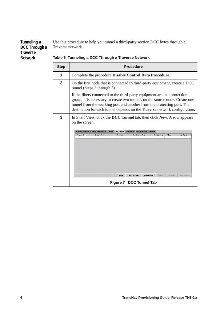
Tunneling a DCC Through a Traverse Network
Use this procedure to help you tunnel a third-party section DCC bytes through a Traverse network.
Table 6 Tunneling a DCC Through a Traverse Network
Step Procedure
1 Complete the procedure Disable Control Data Procedure.
2 On the first node that is connected to third-party equipment, create a DCC tunnel (Steps 3 through 5).
If the fibers connected to the third-party equipment are in a protection group, it is necessary to create two tunnels on the source node. Create one tunnel from the working port and another from the protecting port. The destination for each tunnel depends on the Traverse network configuration.
3 In Shelf View, click the DCC Tunnel tab, then click New. A row appears on the screen.
Figure 7 DCC Tunnel Tab
6 TransNav Provisioning Guide, Release TN5.0.x
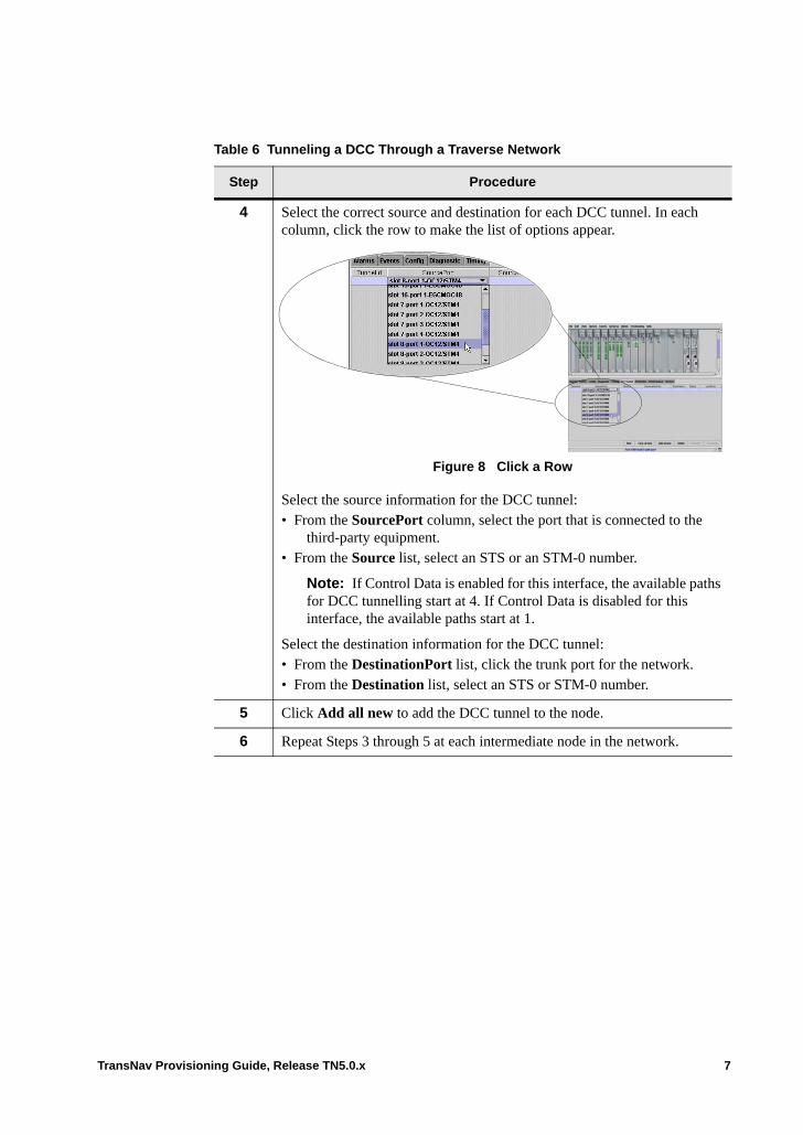
4 Select the correct source and destination for each DCC tunnel. In each column, click the row to make the list of options appear.
Figure 8 Click a Row
Select the source information for the DCC tunnel:• From the SourcePort column, select the port that is connected to the
third-party equipment. • From the Source list, select an STS or an STM-0 number.
Note: If Control Data is enabled for this interface, the available paths for DCC tunnelling start at 4. If Control Data is disabled for this interface, the available paths start at 1.
Select the destination information for the DCC tunnel:• From the DestinationPort list, click the trunk port for the network.• From the Destination list, select an STS or STM-0 number.
5 Click Add all new to add the DCC tunnel to the node.
6 Repeat Steps 3 through 5 at each intermediate node in the network.
Table 6 Tunneling a DCC Through a Traverse Network
Step Procedure
TransNav Provisioning Guide, Release TN5.0.x 7
Definitions of Additional Parameter Values . Definitions of parameters and command buttons not defined in the above procedureare included below:
Status: Can be one of the following values:• Provisioned: The DCC tunnel is provisioned on this node, but not activated.• Activated: The DCC tunnel is provisioned and is carrying DCC traffic.• Act Failed: The activation failed. The reason displays in the Last Error column.• De Act Failed: The deactivation failed. The reason displays in the Last Error column.
Last Error: Displays the reason for a failure. If there are no failures, the field is blank.
Command buttons are as follows:
New: Add a new DCC tunnel to the node.
Clear all new: Clear the DCC tunnels you have just provisioned.
Delete: Delete selected DCC tunnel from the node.
Activate: Activate the selected tunnel on the node to carry third-party DCC traffic.
Deactivate: De-activate the selected the tunnel on the node. This port will stop carrying third-party DCC traffic.
7 On the last node, create a DCC tunnel (see Steps 3 through 5 of this procedure). If this is a SONET DCC tunnel, the destination STS number must match the STS number on the source node. That is, if you use STS #7 on the source interface, you must use STS #7 on the destination interface.
If this is an STM DCC tunnel, the destination STM-0 number must match the STM-0 number on the source node. That is, if you use STM-0 #7 on the source interface, you must use STM-0 #7 on the destination interface.
If the fibers connected to the third-party equipment are in a protection group, it is necessary to create two tunnels on the destination node. Create one tunnel from the trunk carrying the working traffic and another from the trunk carrying the protecting traffic.
Note: The system may take several minutes before the link operation status changes from Disabled to Enabled. For TE-206 nodes, this is also occurs when the node is being rediscovered.
8 The Tunneling a DCC Through a Traverse Network procedure is complete.
Table 6 Tunneling a DCC Through a Traverse Network
Step Procedure
8 TransNav Provisioning Guide, Release TN5.0.x

DCC Tunnel Tab
In a Traverse Shelf View, click the DCC Tunnel tab to display a list of DCC tunnels configured on the node.
Figure 9 DCC Tunnel Tab
The column headings on the DCC Tunnel tab are:
TunnelId: The system-assigned identification for the DCC tunnel.
Source Port: The source port for the DCC tunnel.
Source: The source path for the DCC tunnel. If Control Data is enabled for this interface, the available paths for DCC tunnelling start at 4. If Control Data is disabled for this interface, the available paths start at 1.
Destination Port: The destination port for the DCC tunnel.
Destination: The destination path for the DCC tunnel. The available paths start at 4.
Status: Can be one of the following values:• Provisioned: The DCC tunnel is provisioned on this node, but not activated.• Activated: The DCC tunnel is provisioned and is carrying DCC traffic.• Act Failed: The activation failed. The reason displays in the Last Error column.• De Act Failed: The deactivation failed. The reason displays in the Last Error column.
Last Error: Displays the reason for a failure. If there are no failures, the field is blank.
Command buttons are as follows:
New: Add a new DCC tunnel to the node.
Clear all new: Clear the DCC tunnels you have just provisioned.
Add all new: Add the DCC tunnels you have just provisioned to the list of DCC tunnels on the node.
Delete: Delete selected DCC tunnel from the node.
Activate: Activate the selected tunnel on the node to carry third-party DCC traffic.
Deactivate: De-activate the selected the tunnel on the node. This port will stop carrying third-party DCC traffic.
TransNav Provisioning Guide, Release TN5.0.x 9

10 TransNav Provisioning Guide, Release TN5.0.x

Chapter 5 Configuring IP Quality of Service
Introduction Use IP QoS (IP Quality of Service) to allow or block traffic from certain IP hosts or networks based on entries made in an access control list (ACL). The ACL is searched when IP packets are received from a DCC or backplane DCN. IP packets are dropped or forwarded based on the ACL conditions set.
Outgoing messages are maintained in a classifier table and can be prioritized as High Priority or Best Effort. IP packets originating from the TransNav management server or other Traverse/TE-100 nodes are given High Priority status. IP packets originating from third-party vendor equipment are prioritized as Best Effort unless determined to be High Priority in the Classifier list.
This chapter includes the following topics:• Before You Configure IP Quality of Service• Configuring IP Quality of Service
For information on planning IP addresses in a network, see the Planning and Engineering Guide, Chapter 7—“IP Address Planning.”
This chapter also describes the parameters needed to configure IP QoS:• Global Parameters Tab• Static Classifier Tab• Dynamic Classifier Tab• ACL (Access Control) Tab• Statistics Tab
Important: Use extreme caution when making ACL entries. The TransNav management system uses the multicast address 224.0.0.5 for OSPF messaging. Any ACL entry that blocks this multicast address or the IP addresses of the TransNav management server(s) or the Traverse nodes will cause link failure between the Traverse nodes and/or the TransNav server(s). Force10 strongly recommends that this IP address not be blocked. For more information on internet multicast addresses, see http://www.iana.org/assignments/multicast-addresses.
TransNav Provisioning Guide, Release TN5.0.x 1

Before You Configure IP Quality of Service
Review the information in this topic before you configure IP Quality of Service (IP QoS).
Configuring IP Quality of Service
Use this procedure to block or allow traffic originating from certain IP hosts or networks using an access control list (ACL). The IP addresses defined in the ACL must be as specific as possible. The most specifically masked ACL is used first. If a network IP address overlaps a node IP address that must be accessed, you must add the explicit node IP address to the ACL to allow access. The host ACL overrides the network ACL.
Table 1 IP QoS Requirements
Requirement Reference
Read the information in the Chapter 1—“TN5.0.x Provisioning Overview”
Software
Node is commissioned. Chapter 2—“Discover the Network”
Network is discovered. Chapter 2—“Discover the Network”
2 TransNav Provisioning Guide, Release TN5.0.x
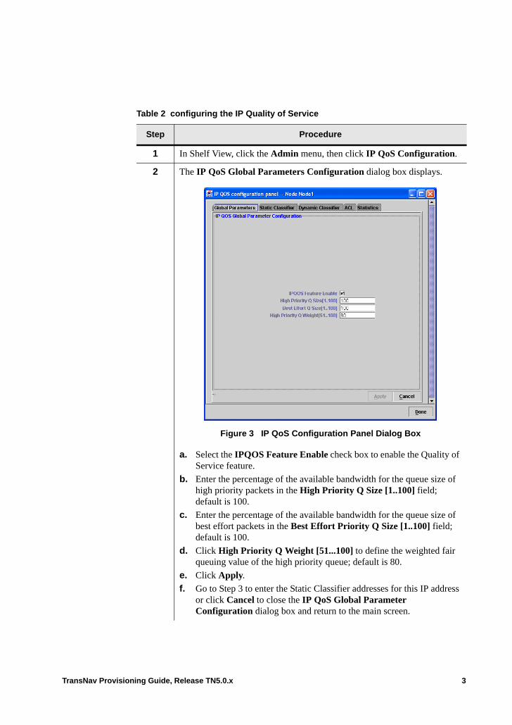
Table 2 configuring the IP Quality of Service
Step Procedure
1 In Shelf View, click the Admin menu, then click IP QoS Configuration.
2 The IP QoS Global Parameters Configuration dialog box displays.
Figure 3 IP QoS Configuration Panel Dialog Box
a. Select the IPQOS Feature Enable check box to enable the Quality of Service feature.
b. Enter the percentage of the available bandwidth for the queue size of high priority packets in the High Priority Q Size [1..100] field; default is 100.
c. Enter the percentage of the available bandwidth for the queue size of best effort packets in the Best Effort Priority Q Size [1..100] field; default is 100.
d. Click High Priority Q Weight [51...100] to define the weighted fair queuing value of the high priority queue; default is 80.
e. Click Apply.
f. Go to Step 3 to enter the Static Classifier addresses for this IP address or click Cancel to close the IP QoS Global Parameter Configuration dialog box and return to the main screen.
TransNav Provisioning Guide, Release TN5.0.x 3
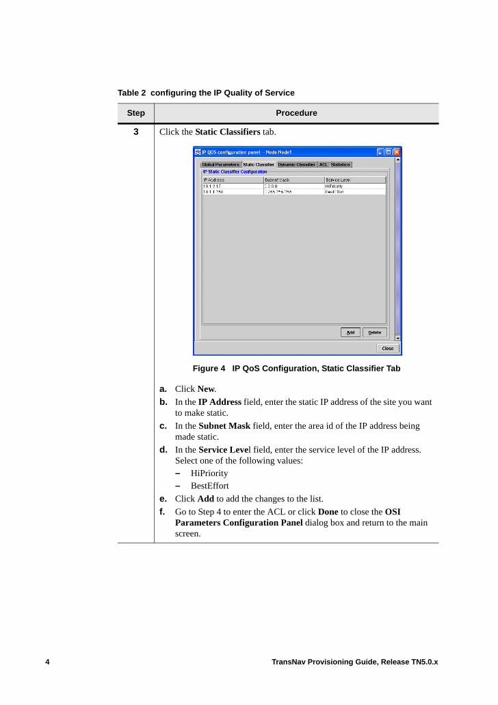
3 Click the Static Classifiers tab.
Figure 4 IP QoS Configuration, Static Classifier Tab
a. Click New.
b. In the IP Address field, enter the static IP address of the site you want to make static.
c. In the Subnet Mask field, enter the area id of the IP address being made static.
d. In the Service Level field, enter the service level of the IP address. Select one of the following values:– HiPriority– BestEffort
e. Click Add to add the changes to the list.
f. Go to Step 4 to enter the ACL or click Done to close the OSI Parameters Configuration Panel dialog box and return to the main screen.
Table 2 configuring the IP Quality of Service
Step Procedure
4 TransNav Provisioning Guide, Release TN5.0.x
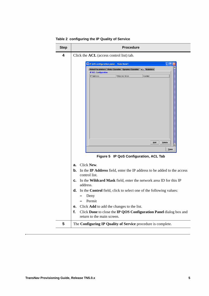
4 Click the ACL (access control list) tab.
Figure 5 IP QoS Configuration, ACL Tab
a. Click New.
b. In the IP Address field, enter the IP address to be added to the access control list.
c. In the Wildcard Mask field, enter the network area ID for this IP address.
d. In the Control field, click to select one of the following values:– Deny– Permit
e. Click Add to add the changes to the list.
f. Click Done to close the IP QOS Configuration Panel dialog box and return to the main screen.
5 The Configuring IP Quality of Service procedure is complete.
Table 2 configuring the IP Quality of Service
Step Procedure
TransNav Provisioning Guide, Release TN5.0.x 5
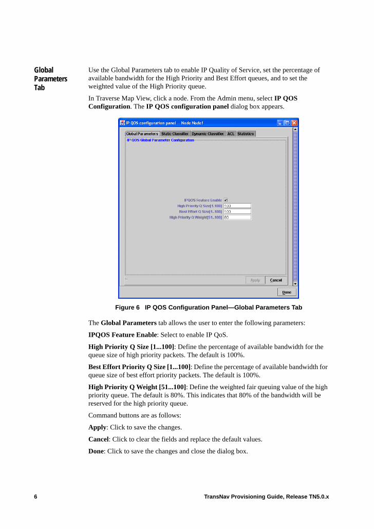
Global Parameters Tab
Use the Global Parameters tab to enable IP Quality of Service, set the percentage of available bandwidth for the High Priority and Best Effort queues, and to set the weighted value of the High Priority queue.
In Traverse Map View, click a node. From the Admin menu, select IP QOS Configuration. The IP QOS configuration panel dialog box appears.
Figure 6 IP QOS Configuration Panel—Global Parameters Tab
The Global Parameters tab allows the user to enter the following parameters:
IPQOS Feature Enable: Select to enable IP QoS.
High Priority Q Size [1...100]: Define the percentage of available bandwidth for the queue size of high priority packets. The default is 100%.
Best Effort Priority Q Size [1...100]: Define the percentage of available bandwidth for queue size of best effort priority packets. The default is 100%.
High Priority Q Weight [51...100]: Define the weighted fair queuing value of the high priority queue. The default is 80%. This indicates that 80% of the bandwidth will be reserved for the high priority queue.
Command buttons are as follows:
Apply: Click to save the changes.
Cancel: Click to clear the fields and replace the default values.
Done: Click to save the changes and close the dialog box.
6 TransNav Provisioning Guide, Release TN5.0.x

Static Classifier Tab
Use the Static Classifier tab to add and maintain individual IP addresses and corresponding subnet (wildcard) masks of third-party vendor equipment in your network. By default, these entries have a Best Effort service level.
In the IP QOS configuration panel dialog box, click the Static Classifier tab.
Figure 7 IP QOS Configuration Panel—Static Classifier Tab
This tab allows the user to view the following parameters:
IP Address: The static IP address of the third-party equipment.
Subnet Mask: Indicates the corresponding Subnet Mask for the IP address.
Service Level: Indicates the service level of the IP address. The valid values are: • HiPriority• BestEffort (default)
Command buttons for the Static Classifier tab are as follows:
Add: Click Add to display the Add Static Classifier dialog box.
Delete: Select an IP Address and click Delete to remove the IP Address from the list.
Close: Click to save the changes and close the dialog box.
TransNav Provisioning Guide, Release TN5.0.x 7
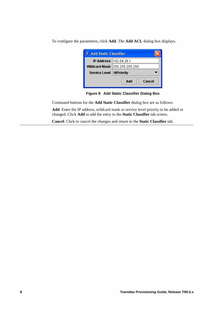
To configure the parameters, click Add. The Add ACL dialog box displays.
Figure 8 Add Static Classifier Dialog Box
Command buttons for the Add Static Classifier dialog box are as follows:
Add: Enter the IP address, wildcard mask or service level priority to be added or changed. Click Add to add the entry to the Static Classifier tab screen.
Cancel: Click to cancel the changes and return to the Static Classifier tab.
8 TransNav Provisioning Guide, Release TN5.0.x

Dynamic Classifier Tab
The Dynamic Classifier tab contains the individual IP addresses and corresponding subnet masks of provisioned equipment, such as the TransNav management server. The list is automatically updated when nodes are inserted or removed from the network, and is the same for every Traverse node in the network. By default, these entries have a High Priority service level.
In the IP QOS configuration panel dialog box, click the Dynamic Classifier tab.
Figure 9 IP QOS Configuration Panel—Dynamic Classifier Tab
Command buttons are as follows:
Refresh: Refreshes the list of existing dynamic IP addresses.
Done: Close the dialog box and return to the main screen.
TransNav Provisioning Guide, Release TN5.0.x 9

ACL (Access Control) Tab
This tab allows users to set the IP forwarding action based on the access control list (ACL) thus allowing traffic from specific IP hosts or networks to be permitted or blocked. The ACL can contain 100 entries.
In the IP QOS configuration panel dialog box, click the ACL tab.
Figure 10 IP QOS Configuration Panel—ACL Tab
The user can view and configure the following parameters:
IP Address: The IP Address on the access control list.
Wildcard Mask: Indicates the wildcard (ACL) mask for the IP address.
Important: When enabling the IP QOS feature, Force10 strongly recommends creating the following ACL entries before any other ACL entries are created.
1. Create one Permit ACL entry for each EMS server.
2. Create one (or more, as needed) Permit ACL entry to cover the entire IP address range of Traverse nodes.
3. Create one Permit ACL entry for the OSPF multicast address (224.0.0.5).
These ACL entries will guard against subsequent ACL range entries from possibly interfering with normal operation.
10 TransNav Provisioning Guide, Release TN5.0.x
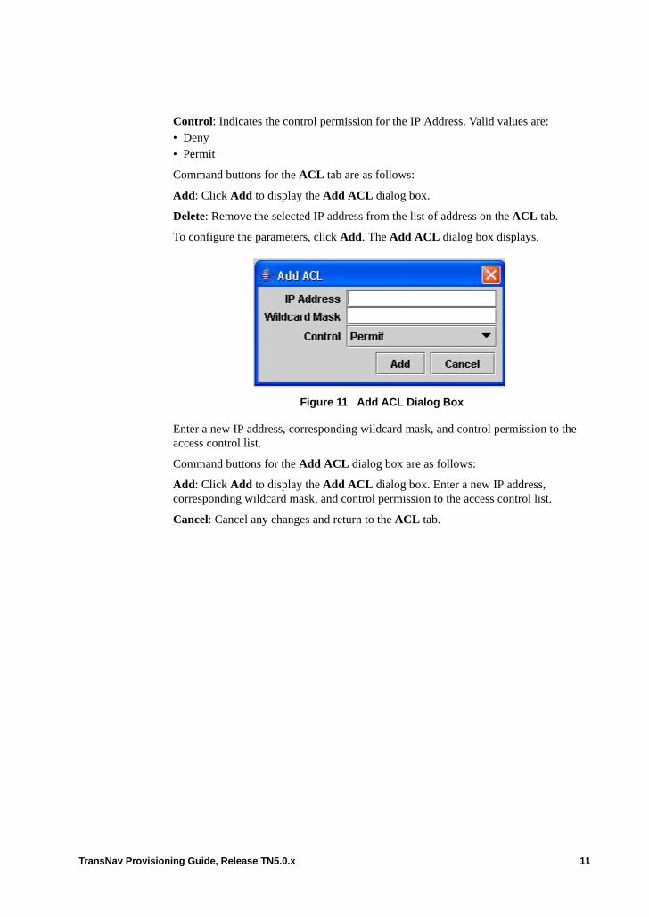
Control: Indicates the control permission for the IP Address. Valid values are:• Deny• Permit
Command buttons for the ACL tab are as follows:
Add: Click Add to display the Add ACL dialog box.
Delete: Remove the selected IP address from the list of address on the ACL tab.
To configure the parameters, click Add. The Add ACL dialog box displays.
Figure 11 Add ACL Dialog Box
Enter a new IP address, corresponding wildcard mask, and control permission to the access control list.
Command buttons for the Add ACL dialog box are as follows:
Add: Click Add to display the Add ACL dialog box. Enter a new IP address, corresponding wildcard mask, and control permission to the access control list.
Cancel: Cancel any changes and return to the ACL tab.
TransNav Provisioning Guide, Release TN5.0.x 11
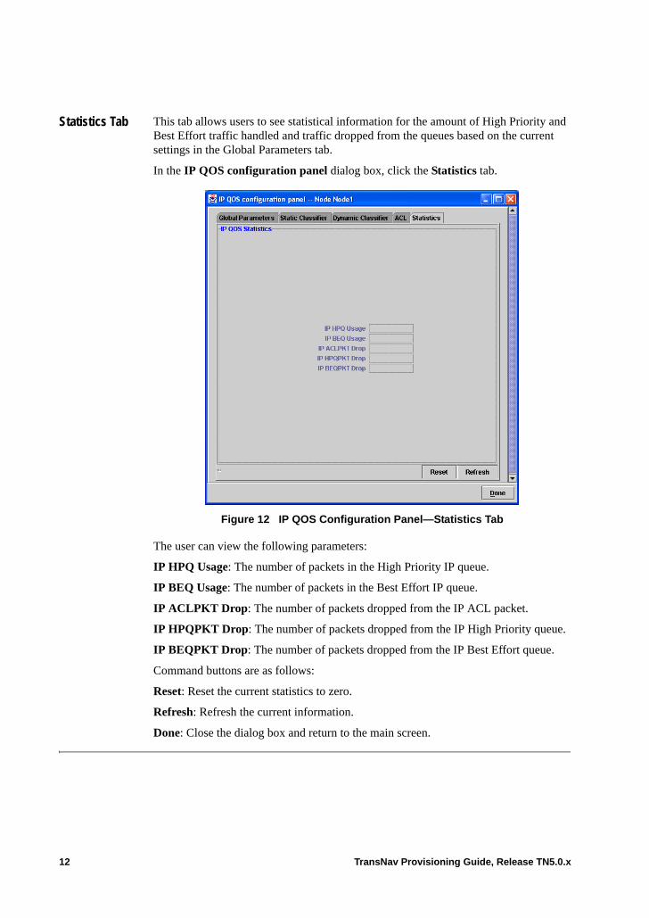
Statistics Tab This tab allows users to see statistical information for the amount of High Priority and Best Effort traffic handled and traffic dropped from the queues based on the current settings in the Global Parameters tab.
In the IP QOS configuration panel dialog box, click the Statistics tab.
Figure 12 IP QOS Configuration Panel—Statistics Tab
The user can view the following parameters:
IP HPQ Usage: The number of packets in the High Priority IP queue.
IP BEQ Usage: The number of packets in the Best Effort IP queue.
IP ACLPKT Drop: The number of packets dropped from the IP ACL packet.
IP HPQPKT Drop: The number of packets dropped from the IP High Priority queue.
IP BEQPKT Drop: The number of packets dropped from the IP Best Effort queue.
Command buttons are as follows:
Reset: Reset the current statistics to zero.
Refresh: Refresh the current information.
Done: Close the dialog box and return to the main screen.
12 TransNav Provisioning Guide, Release TN5.0.x

Chapter 6 Creating a Traverse OSI Gateway Node
Introduction This chapter explains how to configure the Traverse as a gateway network element for third-party equipment (legacy systems and legacy management systems). • Example of the Traverse OSI Gateway Application• Supported Protocol Stack• Before You Create a Traverse OSI Gateway Node• Procedures Required to Create a Traverse OSI Gateway
This chapter also explains the parameters that must be configured to create an OSI gateway node:• NET Tab• TTD Port Tab• TTD ACL Tab• TTD Tab• Man Area Tab
Example of the Traverse OSI Gateway Application
Incorporate the Traverse into networks of third-party systems that are using open system interconnection (OSI) protocols. Configure the Traverse as a gateway network element so that a legacy element management system (EMS) can manage legacy nodes as well as the Traverse node using the TL1 interface.
Figure 1 Traverse OSI Gateway Application
1+1 FacilityProtection
Group
3rd PartyADM A
TL1 overTCP/IP
TL1 overOSI
TL1 overOSI
Ethernet DCN3rd PartyADM E
3rd PartyADM B
3rd PartyADM C
3rd PartyADM DUPSR
3rd PartyEMS
EMS
TransNav
TransNav Provisioning Guide, Release TN5.0.x 1
In this configuration, a legacy EMS can seamlessly transmit and receive management data to and from legacy systems as well as the Traverse system. The optical interfaces to the legacy equipment can be OC-3, OC-12, or OC-48 and are configurable to support either LAPD (link access procedure–D channel) or PPP (point-to-point protocol). Once a link is established, any Layer 3 data can be transmitted over the link.
The presence of a Traverse system in the network does not hinder the legacy systems from discovering each other. The Traverse system is visible to legacy systems and vice versa.
2 TransNav Provisioning Guide, Release TN5.0.x
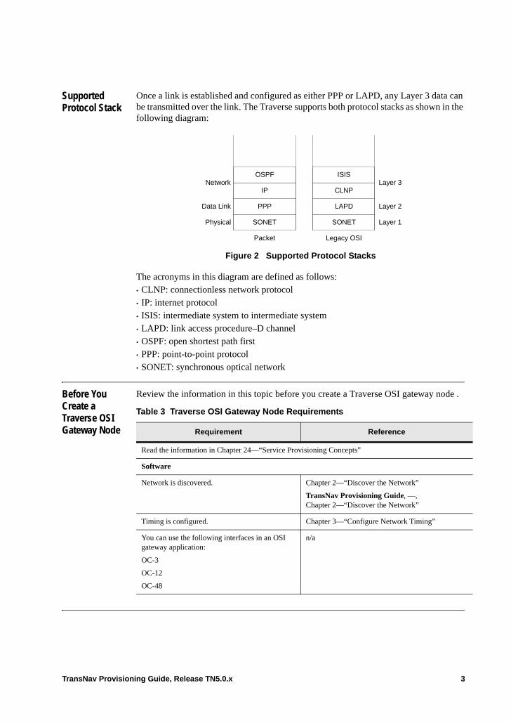
Supported Protocol Stack
Once a link is established and configured as either PPP or LAPD, any Layer 3 data can be transmitted over the link. The Traverse supports both protocol stacks as shown in the following diagram:
Figure 2 Supported Protocol Stacks
The acronyms in this diagram are defined as follows:• CLNP: connectionless network protocol• IP: internet protocol• ISIS: intermediate system to intermediate system• LAPD: link access procedure–D channel• OSPF: open shortest path first• PPP: point-to-point protocol• SONET: synchronous optical network
Before You Create a Traverse OSI Gateway Node
Review the information in this topic before you create a Traverse OSI gateway node .
SONET
PPP
IP
OSPF
SONET
LAPD
CLNP
ISIS
Layer 1
Layer 2
Layer 3
Physical
Data Link
Network
Packet Legacy OSI
Table 3 Traverse OSI Gateway Node Requirements
Requirement Reference
Read the information in Chapter 24—“Service Provisioning Concepts”
Software
Network is discovered. Chapter 2—“Discover the Network”
TransNav Provisioning Guide, —, Chapter 2—“Discover the Network”
Timing is configured. Chapter 3—“Configure Network Timing”
You can use the following interfaces in an OSI gateway application:
OC-3
OC-12
OC-48
n/a
TransNav Provisioning Guide, Release TN5.0.x 3

Procedures Required to Create a Traverse OSI Gateway
Use the Configure the Optical Interface to Use LAPD procedure to help you provision a Traverse system as a gateway network element to legacy ADMs.
To create protection groups for the optical interfaces, see one of the following chapters:• Chapter 17—“Creating and Maintaining UPSR or SNCP Ring Protection Groups”• Chapter 20—“Creating a 1+1 APS/MSP Protection Group”
To create a DCC tunnel on the Traverse, see Chapter 4—“Creating DCC Tunnels.”
These procedures define the mandatory configurable parameters only. For descriptions and definitions of other parameters or screens, see the TransNav Management System GUI Guide.
4 TransNav Provisioning Guide, Release TN5.0.x
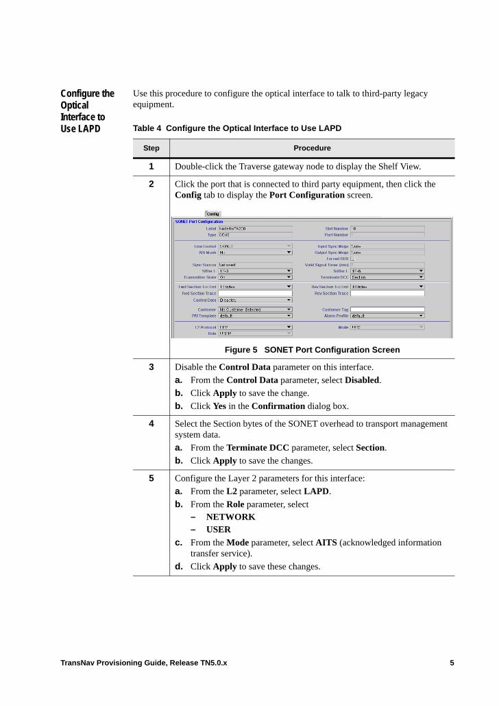
Configure the Optical Interface to Use LAPD
Use this procedure to configure the optical interface to talk to third-party legacy equipment.
Table 4 Configure the Optical Interface to Use LAPD
Step Procedure
1 Double-click the Traverse gateway node to display the Shelf View.
2 Click the port that is connected to third party equipment, then click the Config tab to display the Port Configuration screen.
Figure 5 SONET Port Configuration Screen
3 Disable the Control Data parameter on this interface.
a. From the Control Data parameter, select Disabled.
b. Click Apply to save the change.
b. Click Yes in the Confirmation dialog box.
4 Select the Section bytes of the SONET overhead to transport management system data.
a. From the Terminate DCC parameter, select Section.
b. Click Apply to save the changes.
5 Configure the Layer 2 parameters for this interface:
a. From the L2 parameter, select LAPD.
b. From the Role parameter, select – NETWORK – USER
c. From the Mode parameter, select AITS (acknowledged information transfer service).
d. Click Apply to save these changes.
TransNav Provisioning Guide, Release TN5.0.x 5
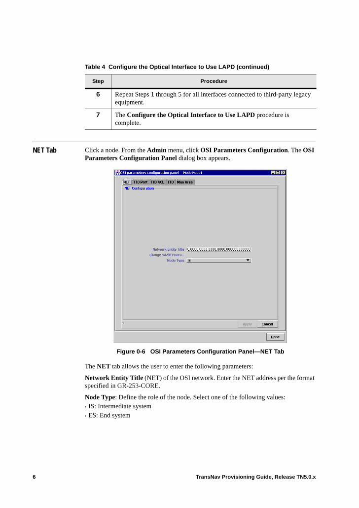
NET Tab Click a node. From the Admin menu, click OSI Parameters Configuration. The OSI Parameters Configuration Panel dialog box appears.
Figure 0-6 OSI Parameters Configuration Panel—NET Tab
The NET tab allows the user to enter the following parameters:
Network Entity Title (NET) of the OSI network. Enter the NET address per the format specified in GR-253-CORE.
Node Type: Define the role of the node. Select one of the following values:• IS: Intermediate system• ES: End system
6 Repeat Steps 1 through 5 for all interfaces connected to third-party legacy equipment.
7 The Configure the Optical Interface to Use LAPD procedure is complete.
Table 4 Configure the Optical Interface to Use LAPD (continued)
Step Procedure
6 TransNav Provisioning Guide, Release TN5.0.x

Command buttons are as follows:
Apply: Click Apply to save the changes.
Cancel: Clear the NET field and replace the default value.
TTD Port Tab On the OSI Parameters Configuration Panel dialog box, click the TTD Port tab.
Figure 0-7 OSI Parameters Configuration Panel—TTD Port Tab
This tab allows the user to view and configure the following parameters:
LV port number: Displays the LV port number. 3081 is default.
Raw port number: Displays the Raw port number. 3082 is default.
Telnet port number: Displays the telnet port number. 3083 is default.
Command buttons are as follows:
Apply: Click Apply to save the changes.
Cancel: Click Cancel to clear the NET field and replace the default value.
Done: Close the dialog box and return to the main screen.
TransNav Provisioning Guide, Release TN5.0.x 7

TTD ACL Tab On the OSI Parameters Configuration Panel dialog box, click the TTD ACL tab.
Figure 0-8 OSI Parameters Configuration Panel—TTD ACL Tab
Command buttons are as follows:
New: Add a new ACL to the list.
Add: Add a new ACL to the list.
Delete: Remove the selected ACL from the list.
Cancel: Cancel any changes and return to the main screen.
Done: Close the dialog box and return to the main screen.
8 TransNav Provisioning Guide, Release TN5.0.x
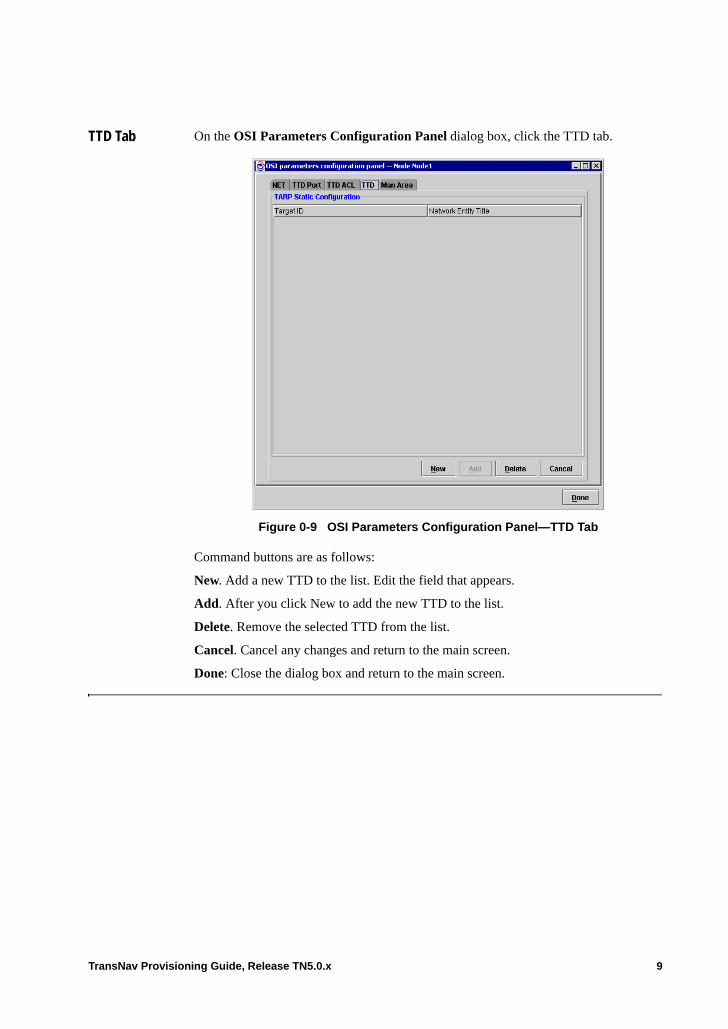
TTD Tab On the OSI Parameters Configuration Panel dialog box, click the TTD tab.
Figure 0-9 OSI Parameters Configuration Panel—TTD Tab
Command buttons are as follows:
New. Add a new TTD to the list. Edit the field that appears.
Add. After you click New to add the new TTD to the list.
Delete. Remove the selected TTD from the list.
Cancel. Cancel any changes and return to the main screen.
Done: Close the dialog box and return to the main screen.
TransNav Provisioning Guide, Release TN5.0.x 9
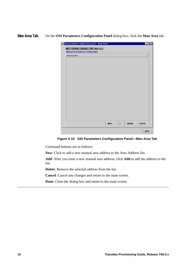
Man Area Tab On the OSI Parameters Configuration Panel dialog box, click the Man Area tab.
Figure 0-10 OSI Parameters Configuration Panel—Man Area Tab
Command buttons are as follows:
New: Click to add a new manual area address to the Area Address list.
Add: After you enter a new manual area address, click Add to add the address to the list.
Delete: Remove the selected address from the list.
Cancel: Cancel any changes and return to the main screen.
Done: Close the dialog box and return to the main screen.
10 TransNav Provisioning Guide, Release TN5.0.x

Chapter 7 Network Auto Discovery
Introduction This chapter describes the following administrative functions selected through the Admin menu on the TransNav management system graphical user interface (GUI):• Network Auto Discovery: Define the gateway node(s) in a domain and easily
identify nodes that have been automatically discovered in the network. • Static Route Information List: Add static routes to a node for management IP
traffic.
Network Auto Discovery
The TransNav management system discovers new nodes in the network, allowing each node in the network to identify the nodes to which it is physically connected. This node-to-node communication allows the entire Traverse network topology to be identified by the TransNav management system. Gateway nodes are manually defined on the Discovery List of the Discovery Sources View dialog box. Nodes that are automatically discovered are also listed on the Discovery List. Operators can select to put nodes listed on the Discovery List in Maintenance Mode to allow the management system to automatically poll the node and keep it synchronized with the server. Nodes can be removed from Maintenance Mode for scheduled maintenance or upgrade to prevent unnecessary alarms being sent to the server.
Note: Automatic polling of discovered nodes may slow system response on systems with a large number of nodes.
TransNav Provisioning Guide, Release TN5.0.x 1
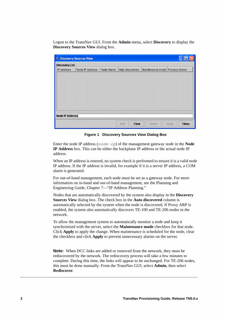
Logon to the TransNav GUI. From the Admin menu, select Discovery to display the Discovery Sources View dialog box.
Figure 1 Discovery Sources View Dialog Box
Enter the node IP address (node-ip) of the management gateway node in the Node IP Address box. This can be either the backplane IP address or the actual node IP address.
When an IP address is entered, no system check is performed to ensure it is a valid node IP address. If the IP address is invalid, for example if it is a server IP address, a COM alarm is generated.
For out-of-band management, each node must be set as a gateway node. For more information on in-band and out-of-band management, see the Planning and Engineering Guide, Chapter 7—“IP Address Planning.”
Nodes that are automatically discovered by the system also display in the Discovery Sources View dialog box. The check box in the Auto discovered column is automatically selected by the system when the node is discovered. If Proxy ARP is enabled, the system also automatically discovers TE-100 and TE-206 nodes in the network.
To allow the management system to automatically monitor a node and keep it synchronized with the server, select the Maintenance mode checkbox for that node. Click Apply to apply the change. When maintenance is scheduled for the node, clear the checkbox and click Apply to prevent unnecessary alarms on the server.
Note: When DCC links are added or removed from the network, they must be rediscovered by the network. The rediscovery process will take a few minutes to complete. During this time, the links will appear to be unchanged. For TE-206 nodes, this must be done manually. From the TransNav GUI, select Admin, then select Rediscover.
2 TransNav Provisioning Guide, Release TN5.0.x
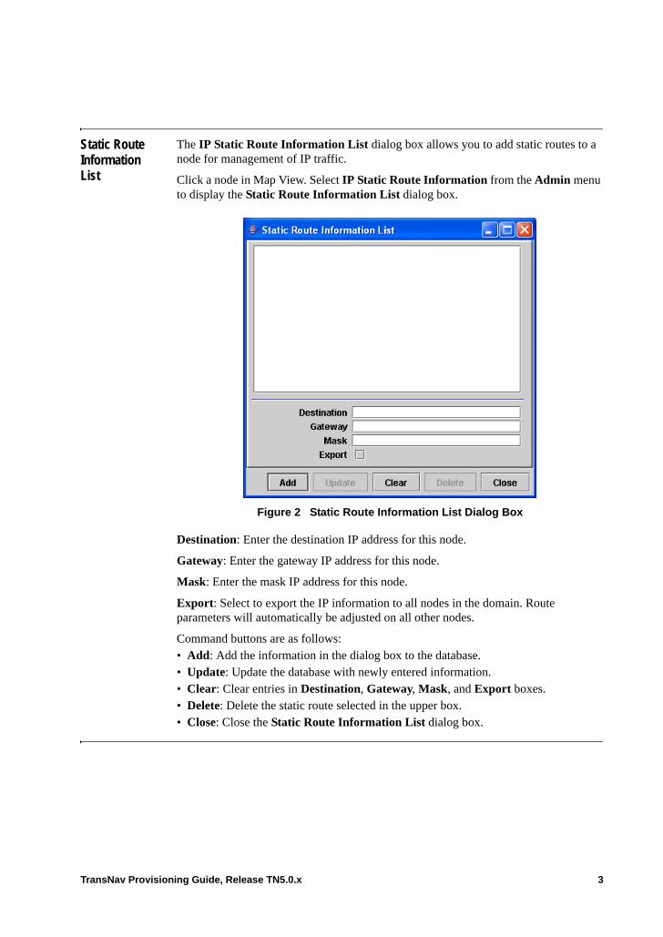
Static Route Information List
The IP Static Route Information List dialog box allows you to add static routes to a node for management of IP traffic.
Click a node in Map View. Select IP Static Route Information from the Admin menu to display the Static Route Information List dialog box.
Figure 2 Static Route Information List Dialog Box
Destination: Enter the destination IP address for this node.
Gateway: Enter the gateway IP address for this node.
Mask: Enter the mask IP address for this node.
Export: Select to export the IP information to all nodes in the domain. Route parameters will automatically be adjusted on all other nodes.
Command buttons are as follows:• Add: Add the information in the dialog box to the database. • Update: Update the database with newly entered information.• Clear: Clear entries in Destination, Gateway, Mask, and Export boxes.• Delete: Delete the static route selected in the upper box.• Close: Close the Static Route Information List dialog box.
TransNav Provisioning Guide, Release TN5.0.x 3

4 TransNav Provisioning Guide, Release TN5.0.x
Chapter 8 Equipment Overview
Introduction Equipment in a TransNav managed network includes nodes, links, cards (modules), ports, and other external equipment. This chapter explains the following information:• When to Change Card Parameters• Protection Groups and Card Configuration• Equipment States• Common Card and Port Configuration Parameters• GCM Card Parameters• Change Card Common Parameters• Configure Protection Parameters• Viewing Port Status Values on SONET and SDH
To create and delete equipment during the preprovisioning process, see Chapter 9—“Creating and Deleting Equipment.”
When to Change Card Parameters
Change parameters for each card:• During the preprovisioning process. Upon discovery of the equipment, the
management server downloads the preprovisioned data to the node.• After the equipment is discovered. If a piece of equipment has not been
preprovisioned when it is discovered, it is assigned default parameters. Change the default values on the Config tab.
Protection Groups and Card Configuration
If you have configured a card as part of a protection group, you can only configure parameters on the working card. Down arrows on selections are grayed out (unavailable) for parameters on the protecting card.
Parameters on a port on a protecting card are automatically set to those configured for the same port on the working card. For example, if Line Format is set to M23 for port 1, slot 2 (the working card), Line Format will also be set to M23 for port 1, slot 1 (the protecting card).
For information on setting up protection groups, see Chapter 15—“Overview of Protection Groups.”
TransNav Provisioning Guide, Release TN5.0.x 1

Equipment States
Icons in the bottom left-hand corner of the Config tab indicate the state of the card or port.
Figure 1 Equipment States
Equipped State: Displays one of the following values:• Equipped: Indicates the equipped state of the card or port. When Equipped, the
equipment is present in the system.• Non-Equipped: When selected, indicates the card or port is Non-Equipped; the
equipment is not present in the system.
Operational State: Displays one of the following values:• Enabled: The administrative state of the card or port is Unlocked.• Disabled: The administrative state of the card or port is Locked.
Administrative State: Click the icon until one of the following values display:• Lock (default for ports): Do not allow the card or port to operate. Changes the
operational state to Disabled. Initiates protection switching, if applicable.• Unlock (default for cards): Allow the card or port to operate.
Operational state
Equipped state
Administrative state
2 TransNav Provisioning Guide, Release TN5.0.x
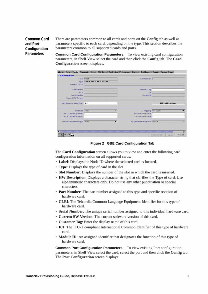
Common Card and Port Configuration Parameters
There are parameters common to all cards and ports on the Config tab as well as parameters specific to each card, depending on the type. This section describes the parameters common to all supported cards and ports.
Common Card Configuration Parameters. To view existing card configuration parameters, in Shelf View select the card and then click the Config tab. The Card Configuration screen displays.
Figure 2 GBE Card Configuration Tab
The Card Configuration screen allows you to view and enter the following card configuration information on all supported cards:• Label: Displays the Node ID where the selected card is located. • Type: Displays the type of card in the slot.• Slot Number: Displays the number of the slot in which the card is inserted.• HW Description: Displays a character string that clarifies the Type of card. Use
alphanumeric characters only. Do not use any other punctuation or special characters.
• Part Number: The part number assigned to this type and specific revision of hardware card.
• CLEI: The Telcordia Common Language Equipment Identifier for this type of hardware card.
• Serial Number: The unique serial number assigned to this individual hardware card.• Current SW Version: The current software version of this card.• Customer Tag: Enter the display name of this card.• ICI: The ITU-T compliant International Common Identifier of this type of hardware
card.• Module ID: An assigned identifier that designates the function of this type of
hardware card.
Common Port Configuration Parameters. To view existing Port configuration parameters, in Shelf View select the card, select the port and then click the Config tab. The Port Configuration screen displays.
TransNav Provisioning Guide, Release TN5.0.x 3

Figure 3 SONET Port Configuration Screen
The Port Configuration screen allows you to view and enter the following port configuration information:
Label: Displays the Node ID where the selected card is located.
Type: Displays the type of card in the slot.
Slot Number: Displays the number of the slot in which the card is inserted.
Port Number (port configuration screens only): Displays the port number on the card of the port being configured.
Line Format: Select one of the following:• ESF (default): Extended superframe format• SF: Superframe format• Unframed: Upon detecting an LOF condition (in Unframed mode), the system does
not:– Raise an LOF alarm– Propagate an AIS– Insert an RAI– Count OOF and SEF framing errors
Line Coding: Displays the line coding technique used for performance monitoring at the line layer. Select one of the following:• AMI (default): alternate mark inversion• B8ZS: bipolar 8-zero substitution
Customer: Select from the list of defined customers.
PM Template: Select from the list of defined performance monitoring templates.
Customer Tag: Alphanumeric name used to identify the port to a customer.
Alarm Profile: Select from the list of defined alarm profiles (of type shelf). Default is default.
4 TransNav Provisioning Guide, Release TN5.0.x
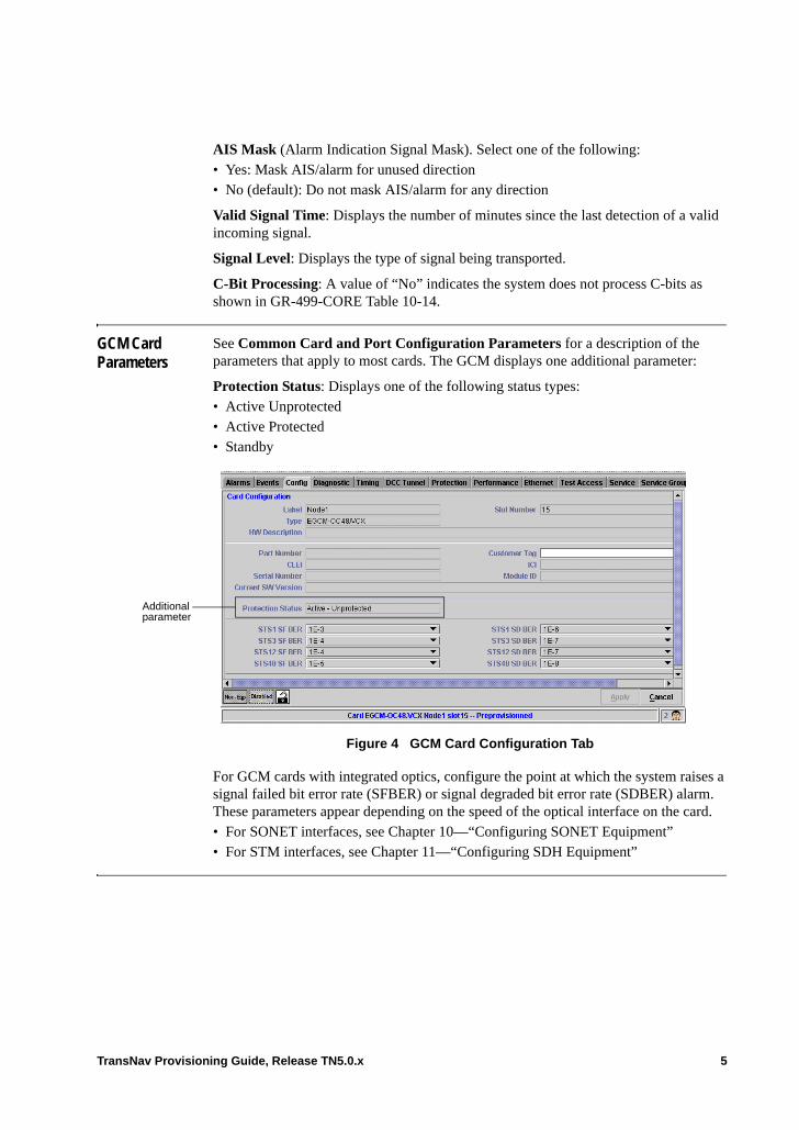
AIS Mask (Alarm Indication Signal Mask). Select one of the following:• Yes: Mask AIS/alarm for unused direction• No (default): Do not mask AIS/alarm for any direction
Valid Signal Time: Displays the number of minutes since the last detection of a valid incoming signal.
Signal Level: Displays the type of signal being transported.
C-Bit Processing: A value of “No” indicates the system does not process C-bits as shown in GR-499-CORE Table 10-14.
GCM Card Parameters
See Common Card and Port Configuration Parameters for a description of the parameters that apply to most cards. The GCM displays one additional parameter:
Protection Status: Displays one of the following status types:• Active Unprotected• Active Protected• Standby
Figure 4 GCM Card Configuration Tab
For GCM cards with integrated optics, configure the point at which the system raises a signal failed bit error rate (SFBER) or signal degraded bit error rate (SDBER) alarm. These parameters appear depending on the speed of the optical interface on the card.• For SONET interfaces, see Chapter 10—“Configuring SONET Equipment”• For STM interfaces, see Chapter 11—“Configuring SDH Equipment”
Additional parameter
TransNav Provisioning Guide, Release TN5.0.x 5
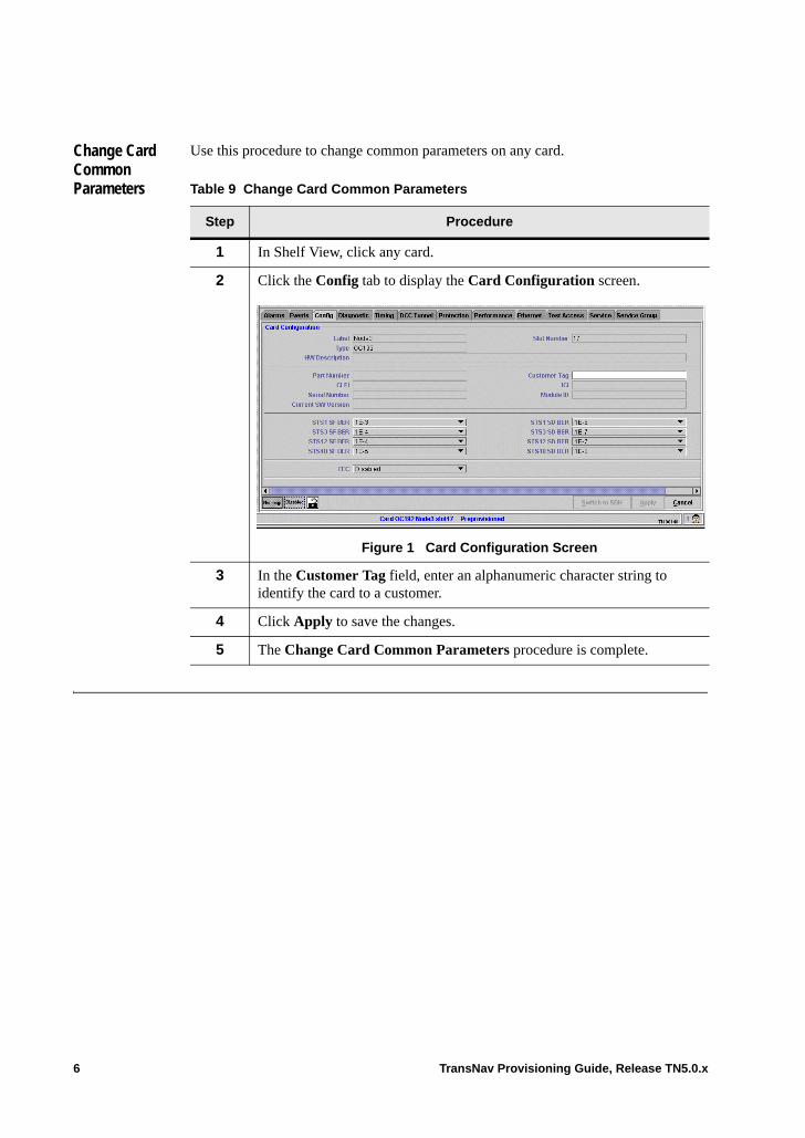
Change Card Common Parameters
Use this procedure to change common parameters on any card.
Table 9 Change Card Common Parameters
Step Procedure
1 In Shelf View, click any card.
2 Click the Config tab to display the Card Configuration screen.
Figure 1 Card Configuration Screen
3 In the Customer Tag field, enter an alphanumeric character string to identify the card to a customer.
4 Click Apply to save the changes.
5 The Change Card Common Parameters procedure is complete.
6 TransNav Provisioning Guide, Release TN5.0.x

Configure Protection Parameters
On the Create Service screen, click the Protection field to display the Protection dialog box.
Figure 2 Protection Dialog Box
Select a Protection Group Type from the drop-down list.
In the Protection Group Type parameter, select one of the following options: • Unprotected (default): Use for services that are unprotected, 1+1 APS protected,
protected with an equipment protection group, or in a 1+1 Path Protection group. • Any: The system finds the best effort of protection through the network. There may
be some spans of unprotected links, but the system creates the service.• Full: The system only creates the service if there is full protection on every transport
link in the network.• 1+1 Path Protected: Select if this service is protected by another service (two services
model). • UPSR Ingress: Select if the service is a VT1.5 or a LO VC service and is creating a
bidirectional path across two interconnected UPSRs or SNCP rings.
After selecting the protection group type, click one of the tabs to configure the applicable parameters:
General. • Revertive: Specifies if the system switches traffic back to the original port or path once the failure condition no longer exists.– Select the checkbox to switch traffic back to the original port or path once the
failure condition no longer exists. – Clear the checkbox for the Protect link or path to continue to carry traffic once
the failure condition no longer exists. • WTR (Wait To Restore) Time: This parameter is configurable only if the checkbox
for the Revertive parameter is selected. Specifies the amount of time (in minutes) for the system to wait before restoring traffic to the original port or path once the failure condition no longer exists. Enter a value between 1 and 60 minutes; default is 5 minutes.
SNCP/UPSR Parameters. • Endpoint (read-only): Displays the endpoints of the service if it is on an UPSR or SNCP protected ring.
TransNav Provisioning Guide, Release TN5.0.x 7

• Ring Id (read-only): Displays the ring ID number if this service is on a UPSR or SNCP ring.
MSSP/BLSR Parameters. • Source Node ID (services provisioned hop-by-hop only): Select the BLSR Node ID where the traffic on this path enters the ring.
• Destination Node ID (services provisioned hop-by-hop only): Select the BLSR Node ID where the traffic on this path exits the ring.
1+1 Path Protection. • HoldOffTimer: Applies only if there is also a 1+1 APS protection group. Allows line protection to switch first before the path switches. If the line switches within the specified time period, the path does not switch. The hold-off timer starts when path protection detects a path failure.The range is 0 to 1000 ms. The default is 0 which means path protection performs protection switching immediately.
8 TransNav Provisioning Guide, Release TN5.0.x
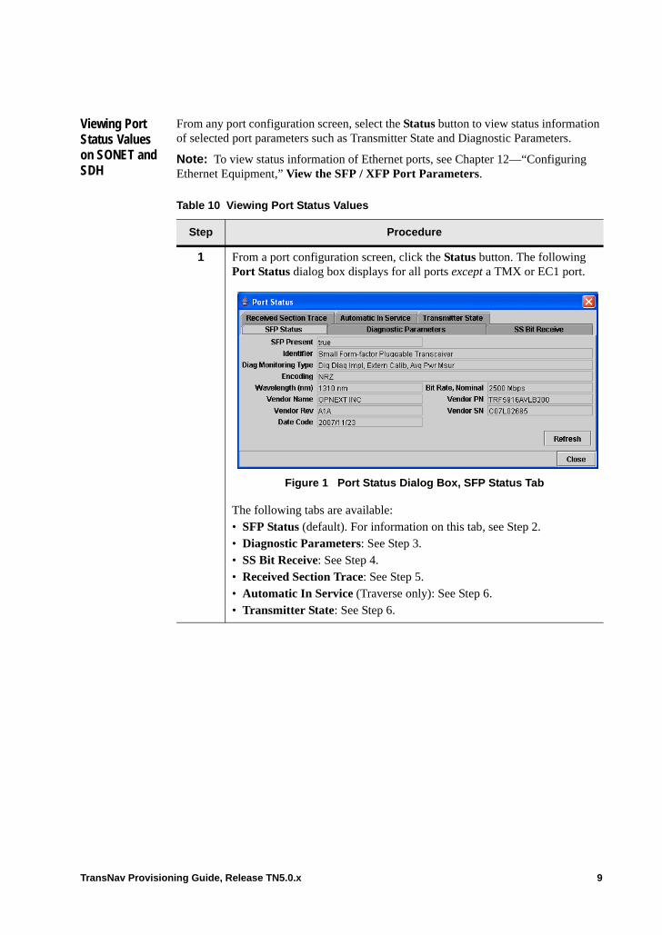
Viewing Port Status Values on SONET and SDH
From any port configuration screen, select the Status button to view status information of selected port parameters such as Transmitter State and Diagnostic Parameters.
Note: To view status information of Ethernet ports, see Chapter 12—“Configuring Ethernet Equipment,” View the SFP / XFP Port Parameters.
Table 10 Viewing Port Status Values
Step Procedure
1 From a port configuration screen, click the Status button. The following Port Status dialog box displays for all ports except a TMX or EC1 port.
Figure 1 Port Status Dialog Box, SFP Status Tab
The following tabs are available:• SFP Status (default). For information on this tab, see Step 2.• Diagnostic Parameters: See Step 3. • SS Bit Receive: See Step 4.• Received Section Trace: See Step 5.• Automatic In Service (Traverse only): See Step 6.• Transmitter State: See Step 6.
TransNav Provisioning Guide, Release TN5.0.x 9
2 Select the SFP Status tab to display the following parameters:• SFP Present: Indicates if a SFP is present. Valid values are True and
False.• Identifier: Indicates the type of port where the transceiver is located.
The port can be an SFP (Small form pluggable) or an optical port.• Diag Monitoring Type: The type of diagnostic monitoring (if any) that
is implemented in the transceiver.• Encoding: The encoding value indicates the serial encoding mechanism
that is the nominal design target of the particular SFP.• Wavelength (nm): Displays the laser wavelength of the transceiver in
nanometers.• Bit Rate, Nominal: Displays the nominal bit rate in increments of 100
Mbps.• Vendor Name: Displays the name of the hardware vendor.• Vendor PN: Displays the vendor’s hardware part number.• Vendor Rev: Displays the vendor’s hardware revision number• Vendor SN: Displays the vendor’s serial number of the hardware.• Date Code: Displays the date the hardware was manufactured.
Click Refresh to refresh the data displayed a few minutes after the card is rebooted. Click Close to close the Port Status dialog box. Click another tab to see additional information.
3 The Diagnostic Parameters tab displays the following information on the SFP or XFP hardware:• Measured Temperature: Indicates the current temperature of the
transceiver. Measured in degrees Celsius (°C). Displays -128 to + 128 ± < 3°C.
• Measured Supply Voltage: Indicates the current voltage the hardware is using. Measured in 100µ volts (micro volts). Displays 0 to 6.55 ± < 3%.
• Measured TX Bias Current: Displays 0 to 131 mA ± <10%. Measured in 2µA.
• Measured TX Output Power: Displays 0 to 6.55 mW (-40 to +8.2 dBm ± <3dB) in units of 0.1µW. This value should be consistent among ports of the same transceiver type. Measured in 10 log [(read value x 10-6)/(10-3)] dBm.
• Measured RX Input Power: Displays 0 to 6.55 mW (-40 to +8.2 dBm ± <3dB) in units of 0.1µW. This value will vary from port to port because of received optical signal power differences. Measured in 10 log [(read value x 10-6)/(10-3)] dBm.
4 The SS Bit Receive tab displays the following information• SS Bit Receive: Indicates the SS bit value that this interface is receiving.
Table 10 Viewing Port Status Values
Step Procedure
10 TransNav Provisioning Guide, Release TN5.0.x

5 The Received Section Trace tab displays the following information: • Rev Section Trace: Indicates the expected access point identifier to be
received in the J0 byte.
6 The Transmitter State tab displays the following information: • Current Transmitter State: Indicates the current state of the
transmitter. Valid values are On and Off.
If the transmitter is off, click Manual Restart to manually restart the transmitter. Click Refresh after a few minutes to refresh the data.
7 For TMX and EC1 (SDH only) ports, the following Port Status dialog box displays:
Figure 2 Port Status Dialog Box, TMX Values
Interface: Indicates the node, slot, port, and subport for the displayed status information.
AINS State (TMX ports on SONET only): Indicates if the Automatic In Service (AINS) parameter is Enabled or Disabled.
AINS Time Remaining (TMX ports on SONET only): Amount of time remaining before the port automatically unlocks.
8 Click Close to return to the Port Configuration screen.
Table 10 Viewing Port Status Values
Step Procedure
TransNav Provisioning Guide, Release TN5.0.x 11

12 TransNav Provisioning Guide, Release TN5.0.x

Chapter 9 Creating and Deleting Equipment
Introduction Equipment in a network includes nodes, links, cards (modules), ports and external devices. This chapter describes how to create and delete equipment, including the preprovisioning process. • Auto-discovery and Pre-provisioning• Create a Node• Node Parameters• Delete a Node• Creating, Replacing, or Deleting a Card• Creating or Deleting Links• View Available Resources on a Link
Auto-discov-ery and Pre-provision-ing
Equipment configuration can be performed with or without the use of preprovisioning. Preprovisioning allows you to perform all configuration functions independent of service activation. Preprovisioning a network or network elements lets you plan for future configurations, facilitating rapid turn-up of new nodes and node expansions. Preprovision nodes on the Primary server. When the Primary server database is imported to the Secondary server, the preprovisioned node appears on the Secondary server.
Using the TransNav management system, you connect directly to a Management Gateway Node (MGN). The management system communicates to the other nodes in the domain through the MGN using a data communications channel (DCC) between the nodes.
Each node uses a process called auto-discovery to learn the addresses of all other nodes in its server domain. After you have commissioned a node with a name and an IP address, the management system discovers and manages all the nodes in the server domain without requiring any other preprovisioned information. For information on configuring auto-discovery of nodes, see Chapter 7—“Network Auto Discovery.”
Upon discovery of the equipment, the TransNav management server downloads the preprovisioned data to the node and builds the graphical representation of the equipment in Map View and Shelf View. If a piece of equipment has not been preprovisioned, it is assigned default parameters. To change parameters from the default values, see Chapter 8—“Equipment Overview.”
TransNav Provisioning Guide, Release TN5.0.x 1
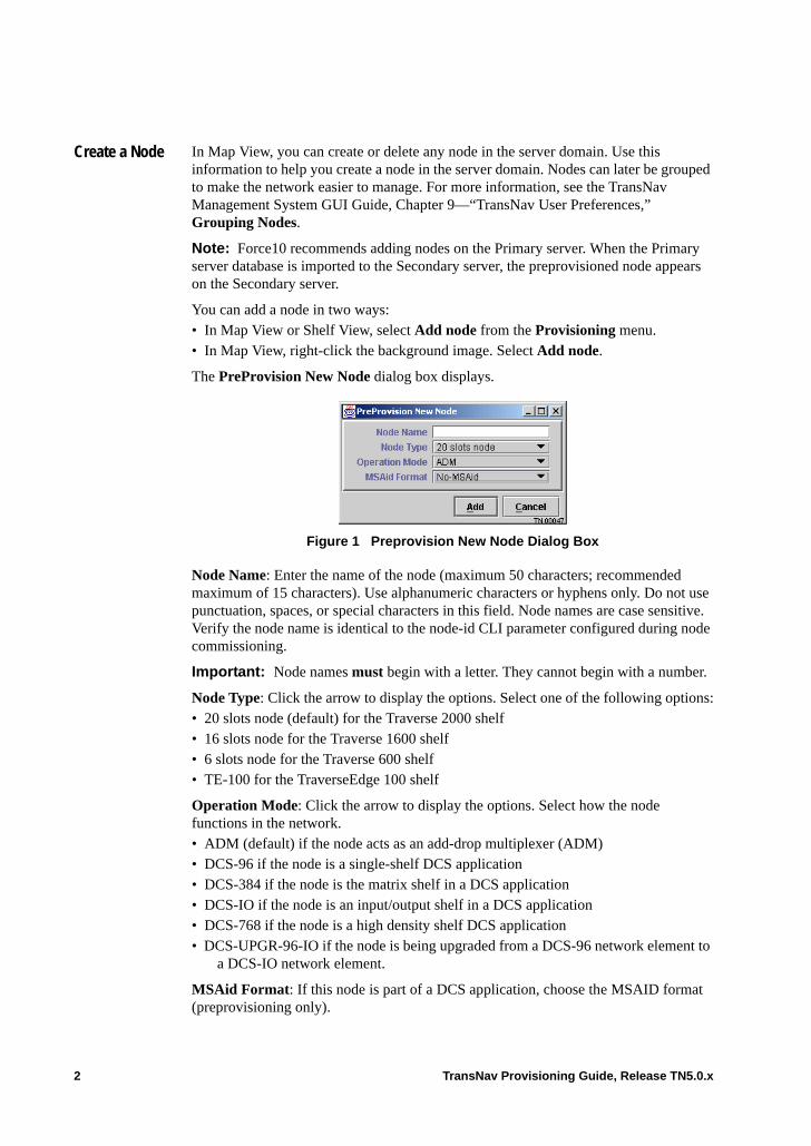
Create a Node In Map View, you can create or delete any node in the server domain. Use this information to help you create a node in the server domain. Nodes can later be grouped to make the network easier to manage. For more information, see the TransNav Management System GUI Guide, Chapter 9—“TransNav User Preferences,” Grouping Nodes.
Note: Force10 recommends adding nodes on the Primary server. When the Primary server database is imported to the Secondary server, the preprovisioned node appears on the Secondary server.
You can add a node in two ways:• In Map View or Shelf View, select Add node from the Provisioning menu.• In Map View, right-click the background image. Select Add node.
The PreProvision New Node dialog box displays.
Figure 1 Preprovision New Node Dialog Box
Node Name: Enter the name of the node (maximum 50 characters; recommended maximum of 15 characters). Use alphanumeric characters or hyphens only. Do not use punctuation, spaces, or special characters in this field. Node names are case sensitive. Verify the node name is identical to the node-id CLI parameter configured during node commissioning.
Important: Node names must begin with a letter. They cannot begin with a number.
Node Type: Click the arrow to display the options. Select one of the following options:• 20 slots node (default) for the Traverse 2000 shelf• 16 slots node for the Traverse 1600 shelf• 6 slots node for the Traverse 600 shelf • TE-100 for the TraverseEdge 100 shelf
Operation Mode: Click the arrow to display the options. Select how the node functions in the network.• ADM (default) if the node acts as an add-drop multiplexer (ADM)• DCS-96 if the node is a single-shelf DCS application• DCS-384 if the node is the matrix shelf in a DCS application• DCS-IO if the node is an input/output shelf in a DCS application• DCS-768 if the node is a high density shelf DCS application• DCS-UPGR-96-IO if the node is being upgraded from a DCS-96 network element to
a DCS-IO network element.
MSAid Format: If this node is part of a DCS application, choose the MSAID format (preprovisioning only).
2 TransNav Provisioning Guide, Release TN5.0.x
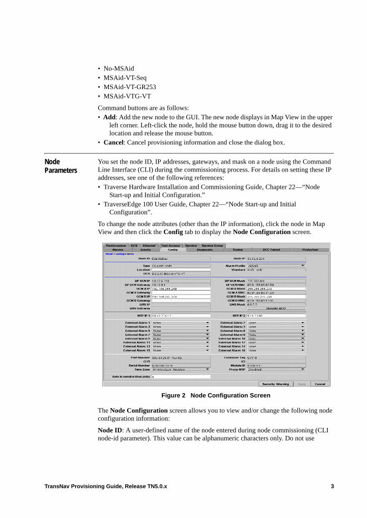
• No-MSAid• MSAid-VT-Seq• MSAid-VT-GR253• MSAid-VTG-VT
Command buttons are as follows:• Add: Add the new node to the GUI. The new node displays in Map View in the upper
left corner. Left-click the node, hold the mouse button down, drag it to the desired location and release the mouse button.
• Cancel: Cancel provisioning information and close the dialog box.
Node Parameters
You set the node ID, IP addresses, gateways, and mask on a node using the Command Line Interface (CLI) during the commissioning process. For details on setting these IP addresses, see one of the following references:• Traverse Hardware Installation and Commissioning Guide, Chapter 22—“Node
Start-up and Initial Configuration.”• TraverseEdge 100 User Guide, Chapter 22—“Node Start-up and Initial
Configuration”.
To change the node attributes (other than the IP information), click the node in Map View and then click the Config tab to display the Node Configuration screen.
Figure 2 Node Configuration Screen
The Node Configuration screen allows you to view and/or change the following node configuration information:
Node ID: A user-defined name of the node entered during node commissioning (CLI node-id parameter). This value can be alphanumeric characters only. Do not use
TransNav Provisioning Guide, Release TN5.0.x 3
punctuation, spaces, or special characters in this field. Additionally, the Node ID is case sensitive. This parameter is required to commission the node and is set using the CLI.
Note: Node names must begin with a letter.
Node IP: Displays the IP address of the node. This address is internal to a TransNav managed network and must be on a separate IP network from any other IP address provisioned on the node (BP DCN IP, EMS IP, and GCM {A | B} IP). This address is required to commission the node and is set using the CLI.
This address is also known as the Router ID in a data network environment.
Force10 recommends using 10.100.100.x where x is between 1 and 254. Use a unique number for each network node.
Force10 recommends that all Node IPs for all nodes in one network be on the same IP network for easier route management.
Type: Displays one of the following options:• 20 slots node (for the Traverse 2000 shelf)• 16 slots node (for the Traverse 1600 shelf)• 6 slots node (for the Traverse 600 shelf)• TE-100 (for the TraverseEdge 100 shelf)
Alarm Profile: Select from the list of defined alarm profiles (of type shelf). Default is default.
Standard: Indicates the standard for this network element: ANSI_only, ITU_default, or ANSI_default.
Location: Enter the location of the node.
DCS: If this is part of a DCS application, this field displays the type of network element (set during node commissioning or preprovisioning) and how the MSAIDs are mapped on the network element.• DCS-96 if the node is a single-shelf DCS application.• DCS-384 if the node is the matrix shelf in a multi-shelf DCS application.• DCS-IO if the node is an input/output shelf in a multi-shelf DCS application.• DCS-768 if the node is a high density shelf DCS application• DCS-UPGR-96-IO if the node is being upgraded from a DCS-96 network element to
a DCS-IO network element.
For explanations of the MSAID and MSAID formats, see the TransNav Management System Provisioning Guide, Chapter 37—“DCS Application Overview.”
BP DCN IP: Displays the IP address assigned to the Ethernet interface on the back of the Traverse shelf. This IP address must be on a separate network from any other IP address provisioned on the node (Node IP, EMS IP, and GCM {A | B} IP). This is set through the CLI during network commissioning.
Enter an IP address if this node is connected to a management server (either directly or through a router).
This address is required on each node that is connected or routed to a management server or on any node with a subtended device.
4 TransNav Provisioning Guide, Release TN5.0.x

Force10 recommends using a different subnet for each site.
BP DCN Mask: Displays the mask IP address for the node BP DCN IP. The value depends on site practices. This is set through the CLI during network commissioning.
BP DCN Gateway: If the node is connected directly to a management server, this field is the address is the IP gateway of the management server. This is set through the CLI during network commissioning.
If there is a router between the management server and this node, this address is the IP address of the port on the router connected to the Ethernet interface on the back of the Traverse shelf.
This parameter is required for each provisioned BP DCN IP.
BP DCN MAC: Displays the MAC address of the BP DCN IP.
GCM A IP: Displays the IP address of the GCM A Ethernet interface.
GCM A Mask: Displays the mask IP address for the GCM A IP.
GCM A Gateway: Displays the gateway IP address for the GCM A IP.
GCM A MAC: Displays the MAC address of the GCM A IP.
GCM B IP: Displays the IP address of the GCM B Ethernet interface.
GCM B Mask: Displays the mask IP address for the GCM B IP.
GCM B Gateway: Displays the gateway IP address for the GCM B IP.
GCM B MAC: Displays the MAC address of the GCM B IP.
EMS IP: Displays the address that is the IP address of the TransNav management server to which this node is connected. This IP address must be on a separate network from any Node IP and GCM {A | B} IP addresses. This is set through the CLI during network commissioning.
For in-band management, this address must be on or routed to the same network as the BP DCN IP of the management gateway node (the node with the physical connection to the management server).
For out-of-band management, this address must be connected or routed to all BP DCN IP addresses.
The value of this parameter depends on site practices.
EMS Mask: Displays the mask IP address for the TransNav management server to which this node is connected. This is set through the CLI during network commissioning.
EMS Gateway: Displays the IP address of the port on the router connected to the Ethernet interface on the back of the Traverse shelf. This address is the same address as BP DCN Gateway. This is set through the CLI during network commissioning.
The above parameter is required for each EMS IP; the value depends on site practices.
Remote ACO: Click this button to acknowledge an external alarm on the selected node.
TransNav Provisioning Guide, Release TN5.0.x 5

NTP (Network Time Protocol) IP 1 Enter the IP address of the Primary server from which the node Time of Day is derived. Time of Day is used for performance monitoring and alarm and event logging.
NTP (Network Time Protocol) IP 2: Enter the IP address of the Secondary server from which the node Time of Day is derived. Time of Day is used for performance monitoring and alarm and event logging.
Note: For instructions on setting the Primary management server as the primary NTP source, see the Software Installation Guide, Chapter 1—“Creating the Management Servers,” Set the Primary Management Server as the Primary NTP Source.
External Alarm 1 to External Alarm 16: The Power Distribution and Alarm Panel (PDAP) provides 16 environmental alarm inputs to report various environmental alarms to the General Control Module (GCM) card. Select from the list of environmental alarms:• HITEMP: High temperature• LWTEMP: Low temperature• OPENDR: Door is open• HIGHHUM: High humidity• LOWHUM: Low humidity• BATDSCHRG: Battery • BATTERY: Battery failure• LWBAVG: Battery power low• POWER: Power failure• GEN: Generator failure• RECT: Rectifier failure• RECTHI: Rectifier high temperature• RECTLO: Rectifier low temperature• CLFAIL: Cooling failure• VENTN: Ventilation failure• FIRE: Fire in the shelf!• FLOOD • SMOKE• TOXICGAS• LEAK• PUMP: Pump failure
Part Number: Displays the part number assigned to the node backplane.
CLEI: Displays the Telcordia Common Language Equipment Identifier (CLEI) for the node backplane.
Serial Number: Displays the unique serial number assigned to the node backplane.
Time Zone: Sets the time and date stamp on alarms and events. Select from a list of time zones. There are five valid time zone locales for the United States:• America/LosAngeles• America/Phoenix
6 TransNav Provisioning Guide, Release TN5.0.x
• America/Denver• America/Chicago• America/New-York
Customer Tag: Displays the Node-ID.
ICI: Displays the ITU-T compliant International Common Identifier (ICI) of the node backplane.
Module ID: An identifier assigned that designates the function of the node backplane.
Proxy ARP: Select to make the node act as a proxy server for the IP subnet. Valid values are: Disabled, Enabled.
Auto in service time (min): (SONET only) Set the amount of time, in minutes, to allow service affecting alarms to be reported. If no port-level or service-level service affecting alarms are reported within the set time, the port or service set up with automatic in service will be unlocked allowing alarms to be reported. Valid values are 0 to 99 hours in one-minute increments. The default value is 30 minutes.
Command buttons are as follows:• Security Warning: Enter a security warning message specific for this Traverse node.
for more information, see the TransNav Management System GUI Guide, Chapter 3—“Administration Procedures,” .
• Apply: Apply node configuration information.• Cancel: Cancel the node configuration information and refresh the tab with the
previously configured information.
Enabling and Configuring SNMP . SNMP can be enabled on the TransNav server to allow SNMP trap information to be viewed on the server. For information, see the Software Installation Guide, Chapter 5—“Enabling SNMP on the Management Server.”
For information on configuring SNMP on a node, see the Operations and Maintenance Guide, Chapter 18—“SNMP Agent and MIBs on Traverse.”
Delete a Node Nodes can be deleted from the network in two ways:• in Map View, right-click the node and select Delete Node • in the navigation tree, right-click the node and select Delete Node
A dialog box appears with the message “Are you sure you would like to delete Node [node name]?” Click Yes to proceed with the delete command or No to cancel the request.
Note: To verify the IP address of a node is deleted, from the server GUI select Admin, then Discovery. The Discovery Sources View dialog box displays. If the IP address of the deleted node is appears in the list, select the IP address to highlight it and click Delete. A confirmation dialog box appears with the message “Are you sure you would like to delete [node IP address]?” Click Yes to proceed with the delete command or No to cancel the request, then click Done.
If node deletion fails from the TransNav GUI, execute the delete node command from the server CLI to ensure that any residual node information is successfully deleted.
TransNav Provisioning Guide, Release TN5.0.x 7

If you delete a preprovisioned node from a Secondary server GUI, it remains on the Primary server. The node is rediscovered by the management system during the auto-discovery process and appears on the Secondary server the next time the Primary server database is imported. To completely delete the preprovisioned node, you must also delete it from the Primary server.
Card Placement
In Shelf View on a Traverse system, you can add a card to a slot and configure interfaces for a card that is not physically inserted into the shelf.
Review the guidelines listed in the TransNav Management System Provisioning Guide, Chapter 56—“Service Endpoints” before you add a card or replace a card in a shelf.
Creating, Replacing, or Deleting a Card
Use the following information to add, delete, or replace a card. • Add a Card• Delete a Card• Replace a Card
Add a Card From Shelf View, right-click the slot into which you want to add a card (module).
Figure 3 Shelf View—Add Card
Select a card name. The card, with its associated ports, displays in the selected slot.
8 TransNav Provisioning Guide, Release TN5.0.x

Delete a Card You can delete a card from the user interface. The management system rediscovers a card physically installed in a shelf during the auto-discovery process.
1. Select the card.
2. Click the lock icon in the bottom left corner to lock the administrative state.
3. Click Apply.
4. Right-click the card and click Delete Card.
Figure 4 Delete or Replace a Card
A dialog box displays which reads “Are you sure you would like to delete slot (number)-[card type]?” Click Yes to proceed with the delete command or No to cancel the request.
A card can only be deleted if its administrative state is Locked. If its administrative state is Unlocked, a Delete Failed dialog box displays.
TransNav Provisioning Guide, Release TN5.0.x 9
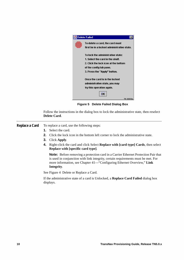
Figure 5 Delete Failed Dialog Box
Follow the instructions in the dialog box to lock the administrative state, then reselect Delete Card.
Replace a Card To replace a card, use the following steps:
1. Select the card.
2. Click the lock icon in the bottom left corner to lock the administrative state.
3. Click Apply.
4. Right-click the card and click Select Replace with [card type] Cards, then select Replace with [specific card type].
Note: Before removing a protection card in a Carrier Ethernet Protection Pair that is used in conjunction with link integrity, certain requirements must be met. For more information, see Chapter 41—“Configuring Ethernet Overview,” Link Integrity.
See Figure 4 Delete or Replace a Card.
If the administrative state of a card is Unlocked, a Replace Card Failed dialog box displays.
10 TransNav Provisioning Guide, Release TN5.0.x
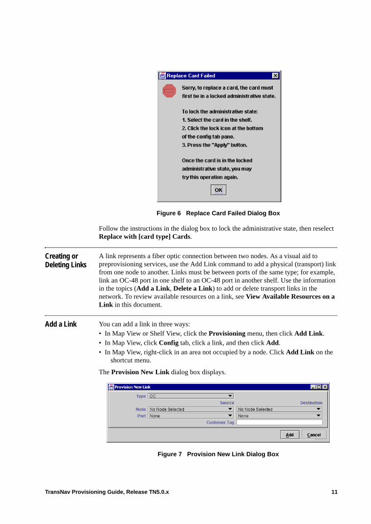
Figure 6 Replace Card Failed Dialog Box
Follow the instructions in the dialog box to lock the administrative state, then reselect Replace with [card type] Cards.
Creating or Deleting Links
A link represents a fiber optic connection between two nodes. As a visual aid to preprovisioning services, use the Add Link command to add a physical (transport) link from one node to another. Links must be between ports of the same type; for example, link an OC-48 port in one shelf to an OC-48 port in another shelf. Use the information in the topics (Add a Link, Delete a Link) to add or delete transport links in the network. To review available resources on a link, see View Available Resources on a Link in this document.
Add a Link You can add a link in three ways:• In Map View or Shelf View, click the Provisioning menu, then click Add Link.• In Map View, click Config tab, click a link, and then click Add.• In Map View, right-click in an area not occupied by a node. Click Add Link on the
shortcut menu.
The Provision New Link dialog box displays.
Figure 7 Provision New Link Dialog Box
TransNav Provisioning Guide, Release TN5.0.x 11
The Provision New Link dialog box allows you to configure the following information:
Type: Select one of the following:• OC• OC3• OC12• OC48• OC192• STM• STM1• STM4• STM16• STM64
Use this field during preprovisioning or when DCC is not used to discover the network to set the Type of link to be used to create the link.
Source:• Node: Select the source node from the list of nodes in the domain.• Port: Select from the list of ports in the source node corresponding to the Type
selected above. Remember that the East port on one node is physically connected to the West port of the next node.
Destination:• Node: Select the destination node from the list of nodes in the domain.• Port: Select from the list of ports in the destination node corresponding to the Type
selected above. Remember that the East port on one node is physically connected to the West port of the next node.
Customer Tag. See the TransNav Management System GUI Guide, Chapter 10—“Generating and Viewing Reports,” Adding Customer Information.
Click Add.
Links for nodes in the same group display in Map View as a gray line. Links between nodes and groups at a different level or with a different background image display as going off the page; the group name and a small Group image (called an off page connector) display:
12 TransNav Provisioning Guide, Release TN5.0.x
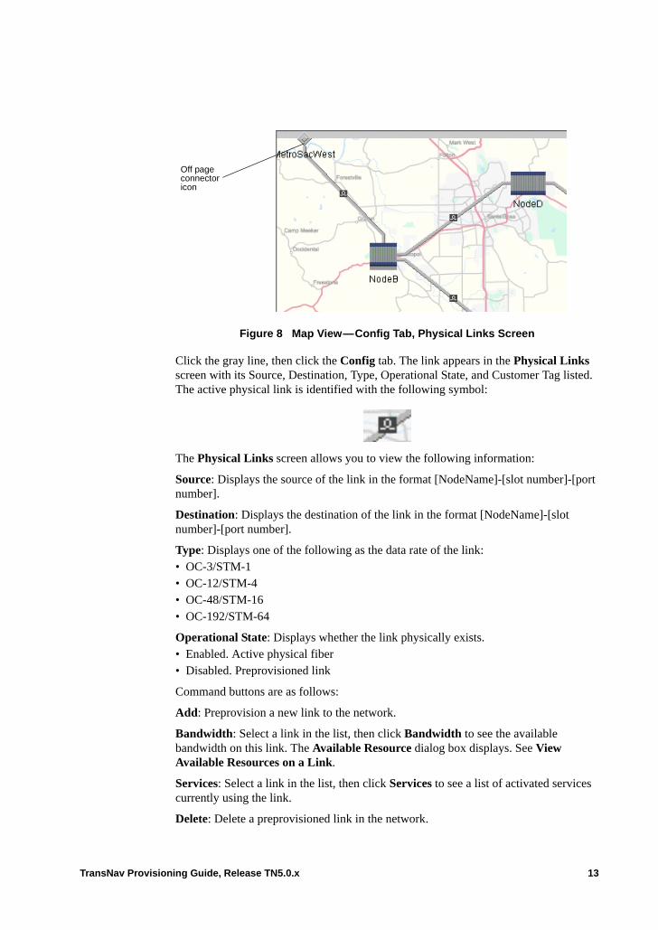
Figure 8 Map View—Config Tab, Physical Links Screen
Click the gray line, then click the Config tab. The link appears in the Physical Links screen with its Source, Destination, Type, Operational State, and Customer Tag listed. The active physical link is identified with the following symbol:
The Physical Links screen allows you to view the following information:
Source: Displays the source of the link in the format [NodeName]-[slot number]-[port number].
Destination: Displays the destination of the link in the format [NodeName]-[slot number]-[port number].
Type: Displays one of the following as the data rate of the link:• OC-3/STM-1• OC-12/STM-4• OC-48/STM-16• OC-192/STM-64
Operational State: Displays whether the link physically exists.• Enabled. Active physical fiber• Disabled. Preprovisioned link
Command buttons are as follows:
Add: Preprovision a new link to the network.
Bandwidth: Select a link in the list, then click Bandwidth to see the available bandwidth on this link. The Available Resource dialog box displays. See View Available Resources on a Link.
Services: Select a link in the list, then click Services to see a list of activated services currently using the link.
Delete: Delete a preprovisioned link in the network.
Off page connector icon
TransNav Provisioning Guide, Release TN5.0.x 13
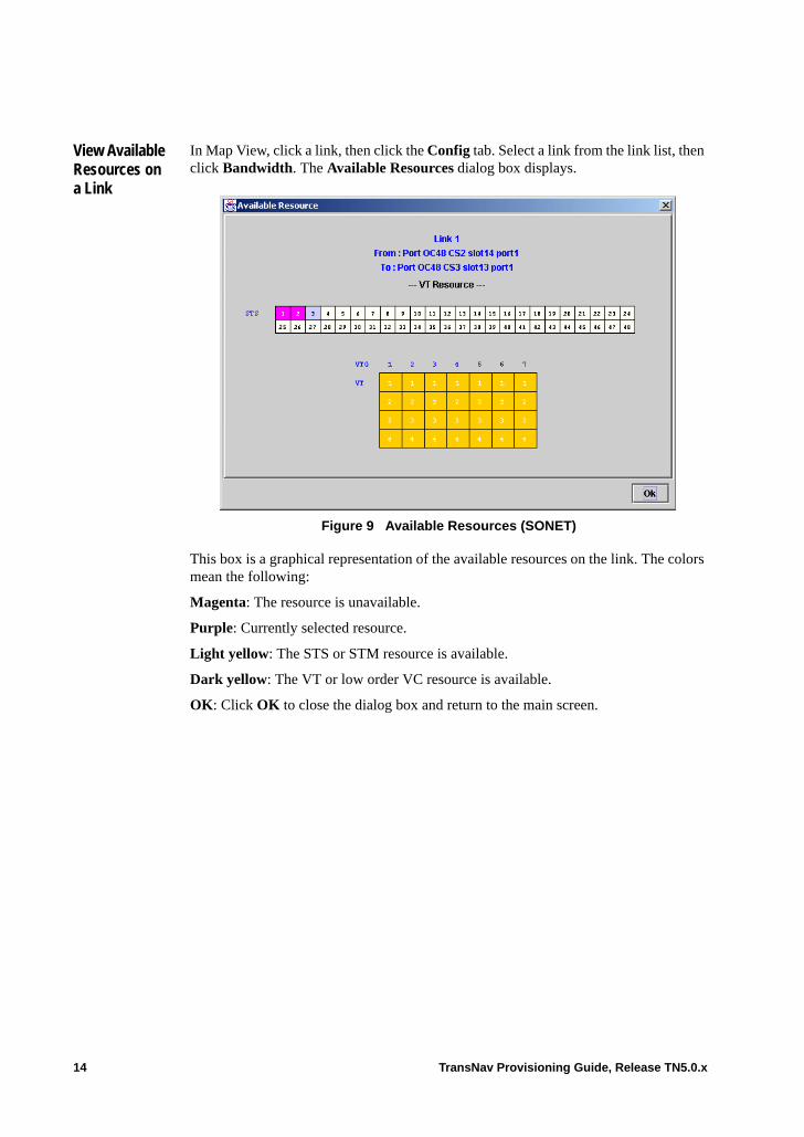
View Available Resources on a Link
In Map View, click a link, then click the Config tab. Select a link from the link list, then click Bandwidth. The Available Resources dialog box displays.
Figure 9 Available Resources (SONET)
This box is a graphical representation of the available resources on the link. The colors mean the following:
Magenta: The resource is unavailable.
Purple: Currently selected resource.
Light yellow: The STS or STM resource is available.
Dark yellow: The VT or low order VC resource is available.
OK: Click OK to close the dialog box and return to the main screen.
14 TransNav Provisioning Guide, Release TN5.0.x

Figure 10 Available Resources (SDH)
Delete a Link To delete a link from Map View, click the Config tab and select the physical link to be removed. Click Delete.
A link which physically exists in the domain is rediscovered by the management system during the auto-discovery process.
TransNav Provisioning Guide, Release TN5.0.x 15

16 TransNav Provisioning Guide, Release TN5.0.x
Chapter 10 Configuring SONET Equipment
Introduction This chapter describes the parameters that appear for each SONET card and port, as well as how to change them. • Before You Change SONET Equipment Configurations• DS1 Numbering• DS1 Mapping• DS3 Framing Format
Information on configuring port parameters in a Traverse or a TE-100 shelf is described in the following procedures:• Change DS1 Mapping Formats• Configure TE-100 Interface Module SONET Parameters• Configure DS1 Port• Configure DS3 Clear Channel Ports• Configure DS3TMX or STS1TMX Port• Configure Subports• Configure EC1 Ports• Change the BER Thresholds for an STS Path• Configure SONET Ports• SONET (OC-N) Card Parameters• SONET Port Parameters
To view the port status values, see Chapter 8—“Equipment Overview,” Viewing Port Status Values on SONET and SDH.
TransNav Provisioning Guide, Release TN5.0.x 1
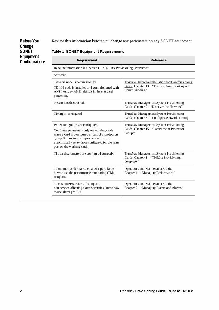
Before You Change SONET Equipment Configurations
Review this information before you change any parameters on any SONET equipment.
Table 1 SONET Equipment Requirements
Requirement Reference
Read the information in Chapter 1—“TN5.0.x Provisioning Overview.”
Software
Traverse node is commissioned
TE-100 node is installed and commissioned with ANSI_only or ANSI_default in the standard parameter.
Traverse Hardware Installation and Commissioning Guide, Chapter 13—“Traverse Node Start-up and Commissioning”
Network is discovered. TransNav Management System Provisioning Guide, Chapter 2—“Discover the Network”
Timing is configured TransNav Management System Provisioning Guide, Chapter 3—“Configure Network Timing”
Protection groups are configured.
Configure parameters only on working cards when a card is configured as part of a protection group. Parameters on a protection card are automatically set to those configured for the same port on the working card.
TransNav Management System Provisioning Guide, Chapter 15—“Overview of Protection Groups”
The card parameters are configured correctly. TransNav Management System Provisioning Guide, Chapter 1—“TN5.0.x Provisioning Overview”
To monitor performance on a DS1 port, know how to use the performance monitoring (PM) templates.
Operations and Maintenance Guide, Chapter 1—“Managing Performance”
To customize service-affecting and non-service-affecting alarm severities, know how to use alarm profiles.
Operations and Maintenance Guide, Chapter 2—“Managing Events and Alarms”
2 TransNav Provisioning Guide, Release TN5.0.x
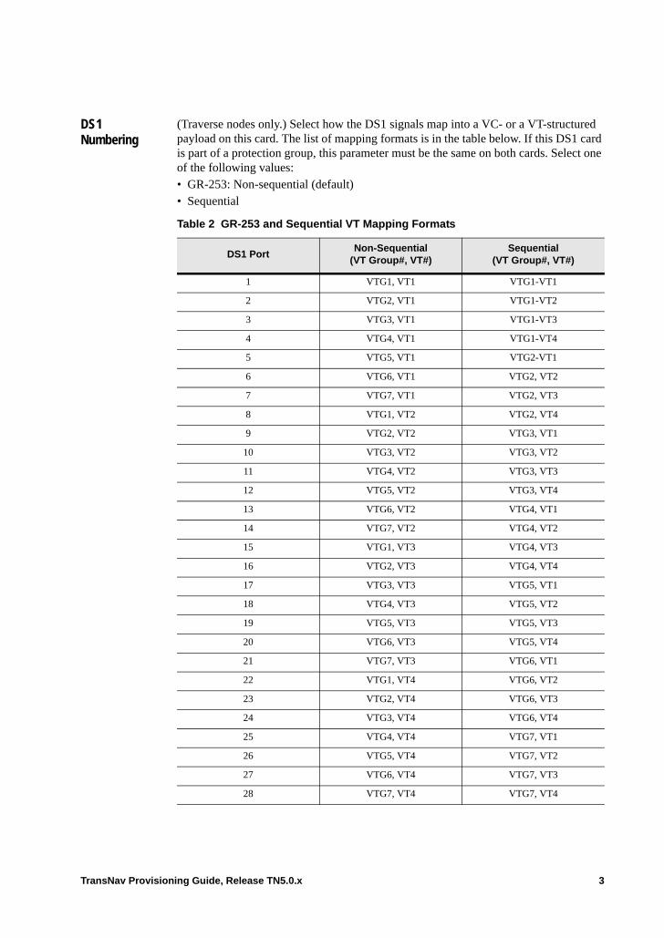
DS1 Numbering
(Traverse nodes only.) Select how the DS1 signals map into a VC- or a VT-structured payload on this card. The list of mapping formats is in the table below. If this DS1 card is part of a protection group, this parameter must be the same on both cards. Select one of the following values: • GR-253: Non-sequential (default) • Sequential
Table 2 GR-253 and Sequential VT Mapping Formats
DS1 PortNon-Sequential
(VT Group#, VT#)Sequential
(VT Group#, VT#)
1 VTG1, VT1 VTG1-VT1
2 VTG2, VT1 VTG1-VT2
3 VTG3, VT1 VTG1-VT3
4 VTG4, VT1 VTG1-VT4
5 VTG5, VT1 VTG2-VT1
6 VTG6, VT1 VTG2, VT2
7 VTG7, VT1 VTG2, VT3
8 VTG1, VT2 VTG2, VT4
9 VTG2, VT2 VTG3, VT1
10 VTG3, VT2 VTG3, VT2
11 VTG4, VT2 VTG3, VT3
12 VTG5, VT2 VTG3, VT4
13 VTG6, VT2 VTG4, VT1
14 VTG7, VT2 VTG4, VT2
15 VTG1, VT3 VTG4, VT3
16 VTG2, VT3 VTG4, VT4
17 VTG3, VT3 VTG5, VT1
18 VTG4, VT3 VTG5, VT2
19 VTG5, VT3 VTG5, VT3
20 VTG6, VT3 VTG5, VT4
21 VTG7, VT3 VTG6, VT1
22 VTG1, VT4 VTG6, VT2
23 VTG2, VT4 VTG6, VT3
24 VTG3, VT4 VTG6, VT4
25 VTG4, VT4 VTG7, VT1
26 VTG5, VT4 VTG7, VT2
27 VTG6, VT4 VTG7, VT3
28 VTG7, VT4 VTG7, VT4
TransNav Provisioning Guide, Release TN5.0.x 3
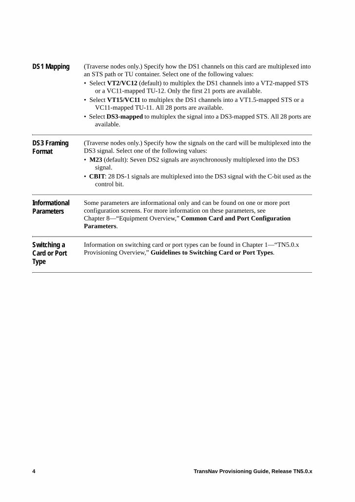
DS1 Mapping (Traverse nodes only.) Specify how the DS1 channels on this card are multiplexed into an STS path or TU container. Select one of the following values:• Select VT2/VC12 (default) to multiplex the DS1 channels into a VT2-mapped STS
or a VC11-mapped TU-12. Only the first 21 ports are available.• Select VT15/VC11 to multiplex the DS1 channels into a VT1.5-mapped STS or a
VC11-mapped TU-11. All 28 ports are available.• Select DS3-mapped to multiplex the signal into a DS3-mapped STS. All 28 ports are
available.
DS3 Framing Format
(Traverse nodes only.) Specify how the signals on the card will be multiplexed into the DS3 signal. Select one of the following values:• M23 (default): Seven DS2 signals are asynchronously multiplexed into the DS3
signal.• CBIT: 28 DS-1 signals are multiplexed into the DS3 signal with the C-bit used as the
control bit.
Informational Parameters
Some parameters are informational only and can be found on one or more port configuration screens. For more information on these parameters, see Chapter 8—“Equipment Overview,” Common Card and Port Configuration Parameters.
Switching a Card or Port Type
Information on switching card or port types can be found in Chapter 1—“TN5.0.x Provisioning Overview,” Guidelines to Switching Card or Port Types.
4 TransNav Provisioning Guide, Release TN5.0.x

Change DS1 Mapping Formats
There are configurable parameters on the card that control how DS1 channels on the card (module) map to a VT payload or multiplex into an STS path. For Traverse nodes, this is the DS1 card. The channels on the card can also map or multiple to an STM path. For TE-100 nodes, this is the interface card.
Important: Changing these parameters on the DS1 card is service affecting. You cannot complete this procedure if the card is carrying traffic (if there are services activated).
Table 3 Change DS1 Mapping Formats
Step Procedure
1 In Shelf View, click a card. On Traverse nodes, click a DS1 card. On TE-100 nodes, click the interface card.
2 Click the Config tab to display the Card Configuration screen.
Figure 4 Traverse Nodes: DS1 Card, Config Tab
Figure 5 TE-100 Nodes: Tributary Module, Config Tab
TransNav Provisioning Guide, Release TN5.0.x 5
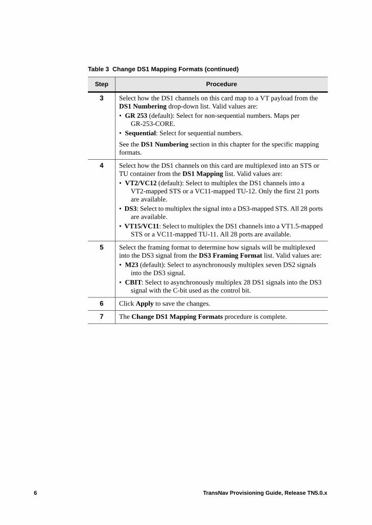
3 Select how the DS1 channels on this card map to a VT payload from the DS1 Numbering drop-down list. Valid values are: • GR 253 (default): Select for non-sequential numbers. Maps per
GR-253-CORE.• Sequential: Select for sequential numbers.
See the DS1 Numbering section in this chapter for the specific mapping formats.
4 Select how the DS1 channels on this card are multiplexed into an STS or TU container from the DS1 Mapping list. Valid values are:• VT2/VC12 (default): Select to multiplex the DS1 channels into a
VT2-mapped STS or a VC11-mapped TU-12. Only the first 21 ports are available.
• DS3: Select to multiplex the signal into a DS3-mapped STS. All 28 ports are available.
• VT15/VC11: Select to multiplex the DS1 channels into a VT1.5-mapped STS or a VC11-mapped TU-11. All 28 ports are available.
5 Select the framing format to determine how signals will be multiplexed into the DS3 signal from the DS3 Framing Format list. Valid values are:• M23 (default): Select to asynchronously multiplex seven DS2 signals
into the DS3 signal.• CBIT: Select to asynchronously multiplex 28 DS1 signals into the DS3
signal with the C-bit used as the control bit.
6 Click Apply to save the changes.
7 The Change DS1 Mapping Formats procedure is complete.
Table 3 Change DS1 Mapping Formats (continued)
Step Procedure
6 TransNav Provisioning Guide, Release TN5.0.x
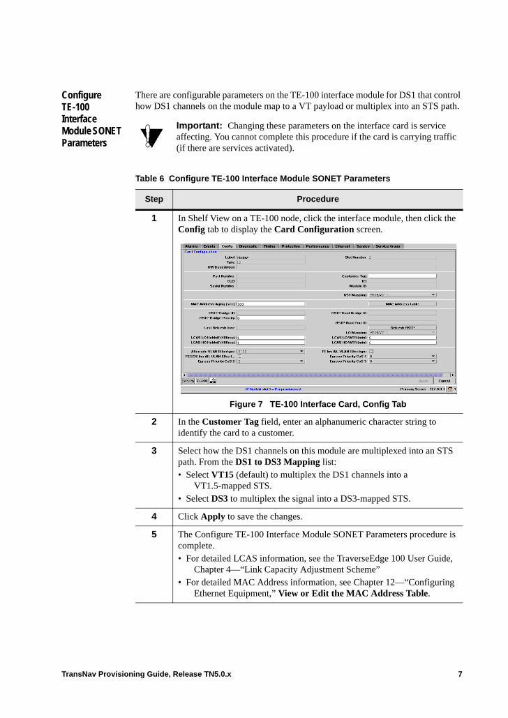
Configure TE-100 Interface Module SONET Parameters
There are configurable parameters on the TE-100 interface module for DS1 that control how DS1 channels on the module map to a VT payload or multiplex into an STS path.
Important: Changing these parameters on the interface card is service affecting. You cannot complete this procedure if the card is carrying traffic (if there are services activated).
Table 6 Configure TE-100 Interface Module SONET Parameters
Step Procedure
1 In Shelf View on a TE-100 node, click the interface module, then click the Config tab to display the Card Configuration screen.
Figure 7 TE-100 Interface Card, Config Tab
2 In the Customer Tag field, enter an alphanumeric character string to identify the card to a customer.
3 Select how the DS1 channels on this module are multiplexed into an STS path. From the DS1 to DS3 Mapping list:• Select VT15 (default) to multiplex the DS1 channels into a
VT1.5-mapped STS.• Select DS3 to multiplex the signal into a DS3-mapped STS.
4 Click Apply to save the changes.
5 The Configure TE-100 Interface Module SONET Parameters procedure is complete.• For detailed LCAS information, see the TraverseEdge 100 User Guide,
Chapter 4—“Link Capacity Adjustment Scheme”• For detailed MAC Address information, see Chapter 12—“Configuring
Ethernet Equipment,” View or Edit the MAC Address Table.
TransNav Provisioning Guide, Release TN5.0.x 7
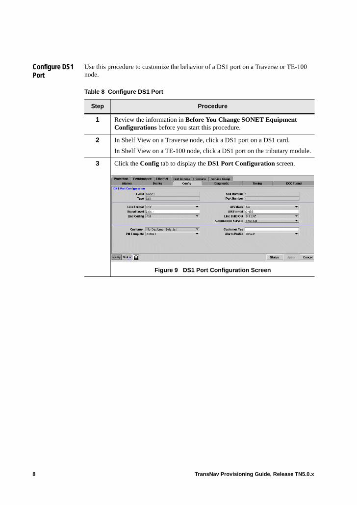
Configure DS1 Port
Use this procedure to customize the behavior of a DS1 port on a Traverse or TE-100 node.
Table 8 Configure DS1 Port
Step Procedure
1 Review the information in Before You Change SONET Equipment Configurations before you start this procedure.
2 In Shelf View on a Traverse node, click a DS1 port on a DS1 card.
In Shelf View on a TE-100 node, click a DS1 port on the tributary module.
3 Click the Config tab to display the DS1 Port Configuration screen.
Figure 9 DS1 Port Configuration Screen
8 TransNav Provisioning Guide, Release TN5.0.x
4 Change any of the following parameters for the DS1 interface:
Line Format: Select one of the following:• ESF (default): Extended superframe format• SF: Superframe format• Unframed: Upon detecting an LOF condition (in Unframed mode), the
system does not:– Raise an LOF alarm– Propagate an AIS– Insert an RAI– Count OOF and SEF framing errors
Line Coding: Displays the line coding technique used for performance monitoring at the line layer. Select one of the following:• AMI (default): alternate mark inversion• B8ZS: bipolar 8-zero substitution
AIS Mask (Alarm Indication Signal Mask). Select one of the following:• Yes: Mask AIS/alarm for unused direction• No (default): Do not mask AIS/alarm for any direction
AIS Format: Select one of the following:• NAS (default): North America Standard. All C-bits shall be set to 0. All
X-bits shall be set to 1. The information bits shall be set to a 1010... repeating sequence, with a 1 immediately following each of the control bit positions.
• ONES: Unformatted all ones.
Line Build Out: Displays the distance from the subscriber interface to the physical port on the node. Select one of the following:• 0 – 133 ft (default)• 133 – 266 ft• 266 – 399 ft• 399 – 533 ft• 533 – 665 ft
Table 8 Configure DS1 Port (continued)
Step Procedure
TransNav Provisioning Guide, Release TN5.0.x 9
Automatic In Service: (Available on Traverse node SONET services only.) Use to suppress the line level alarms, line and section level TCA events, and PM reports for ports that are not currently in service. Line level alarms, line and section level TCA events, and PM reports will be automatically initiated when the port goes in service. • Enabled (default): Select to suppress the line level alarms, line and
section level TCA events, and PM reports for ports that are not currently in service.
• Disabled: Select to report the line level alarms and PM reports for ports that are not in service.
Ports must be locked for Auto In Service to be functional. Alarms, TCA events, and PM reports are generated on unlocked ports only.
Note: Manually locking or unlocking the port will not affect the Automatic In Service parameter. The parameter must be set to Enabled and the port must be locked to suppress port line level alarms and PM reports.
5 Change any of the following general parameters for the interface:
Customer: Select from the list of defined customers.
Customer Tag: Enter an alphanumeric character string to identify the card to a customer.
PM Template: Select from the list of defined performance monitoring templates (of type ds1_ptp_pm). The default value is default, which contains default thresholds for performance monitoring parameters and thresholds for DS1 ports. For more information, see the Operations and Maintenance Guide, Chapter 4—“Managing Performance.”
Alarm Profile: Select from the list of defined alarm profiles (of type ds1_ptp) to customize service-affecting and non-service-affecting alarm severities. The default is the default ds1_ptp alarm profile.
6 Click the Lock icon to unlock the port. The port must be unlocked to apply changes and monitor potential problems by generating alarms. The Lock icon is located in the lower left corner of the screen.
7 Click Apply to save the changes.
8 The Configure DS1 Port procedure is complete.
Table 8 Configure DS1 Port (continued)
Step Procedure
10 TransNav Provisioning Guide, Release TN5.0.x
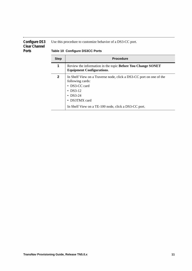
Configure DS3 Clear Channel Ports
Use this procedure to customize behavior of a DS3-CC port.
Table 10 Configure DS3CC Ports
Step Procedure
1 Review the information in the topic Before You Change SONET Equipment Configurations.
2 In Shelf View on a Traverse node, click a DS3-CC port on one of the following cards:• DS3-CC card• DS3-12• DS3-24• DS3TMX card
In Shelf View on a TE-100 node, click a DS3-CC port.
TransNav Provisioning Guide, Release TN5.0.x 11
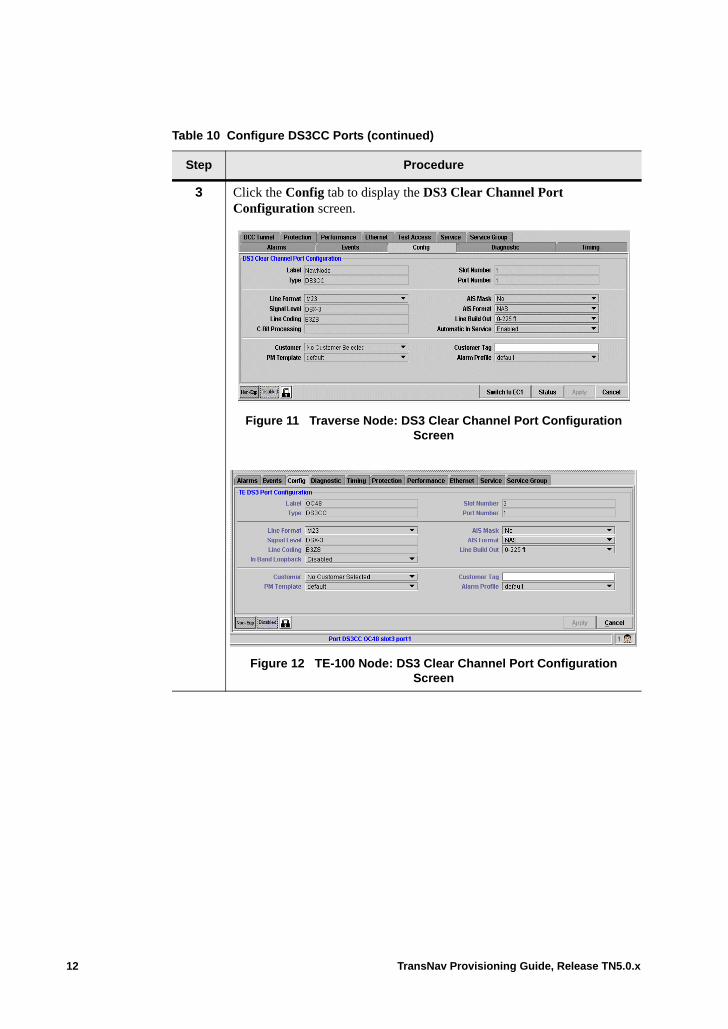
3 Click the Config tab to display the DS3 Clear Channel Port Configuration screen.
Figure 11 Traverse Node: DS3 Clear Channel Port Configuration Screen
Figure 12 TE-100 Node: DS3 Clear Channel Port Configuration Screen
Table 10 Configure DS3CC Ports (continued)
Step Procedure
12 TransNav Provisioning Guide, Release TN5.0.x
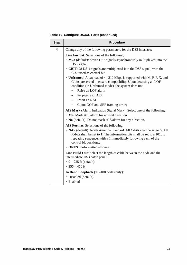
4 Change any of the following parameters for the DS3 interface:
Line Format: Select one of the following:• M23 (default): Seven DS2 signals asynchronously multiplexed into the
DS3 signal.• CBIT: 28 DS-1 signals are multiplexed into the DS3 signal, with the
C-bit used as control bit.• Unframed: A payload of 44.210 Mbps is supported with M, F, P, X, and
C bits preserved to ensure compatibility. Upon detecting an LOF condition (in Unframed mode), the system does not:– Raise an LOF alarm– Propagate an AIS– Insert an RAI– Count OOF and SEF framing errors
AIS Mask (Alarm Indication Signal Mask): Select one of the following:• Yes: Mask AIS/alarm for unused direction.• No (default): Do not mask AIS/alarm for any direction.
AIS Format: Select one of the following:• NAS (default): North America Standard. All C-bits shall be set to 0. All
X-bits shall be set to 1. The information bits shall be set to a 1010... repeating sequence, with a 1 immediately following each of the control bit positions.
• ONES: Unformatted all ones.
Line Build Out: Select the length of cable between the node and the intermediate DS3 patch panel: • 0 – 225 ft (default)• 255 – 450 ft
In Band Loopback (TE-100 nodes only): • Disabled (default)• Enabled
Table 10 Configure DS3CC Ports (continued)
Step Procedure
TransNav Provisioning Guide, Release TN5.0.x 13
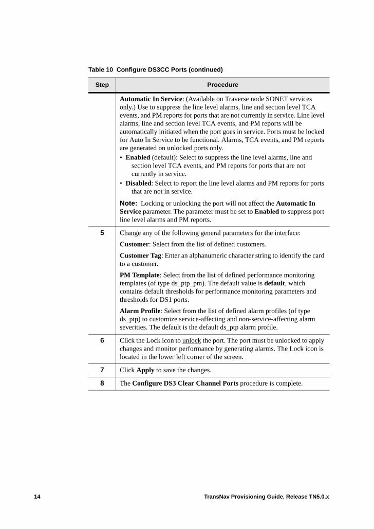
Automatic In Service: (Available on Traverse node SONET services only.) Use to suppress the line level alarms, line and section level TCA events, and PM reports for ports that are not currently in service. Line level alarms, line and section level TCA events, and PM reports will be automatically initiated when the port goes in service. Ports must be locked for Auto In Service to be functional. Alarms, TCA events, and PM reports are generated on unlocked ports only. • Enabled (default): Select to suppress the line level alarms, line and
section level TCA events, and PM reports for ports that are not currently in service.
• Disabled: Select to report the line level alarms and PM reports for ports that are not in service.
Note: Locking or unlocking the port will not affect the Automatic In Service parameter. The parameter must be set to Enabled to suppress port line level alarms and PM reports.
5 Change any of the following general parameters for the interface:
Customer: Select from the list of defined customers.
Customer Tag: Enter an alphanumeric character string to identify the card to a customer.
PM Template: Select from the list of defined performance monitoring templates (of type ds_ptp_pm). The default value is default, which contains default thresholds for performance monitoring parameters and thresholds for DS1 ports.
Alarm Profile: Select from the list of defined alarm profiles (of type ds_ptp) to customize service-affecting and non-service-affecting alarm severities. The default is the default ds_ptp alarm profile.
6 Click the Lock icon to unlock the port. The port must be unlocked to apply changes and monitor performance by generating alarms. The Lock icon is located in the lower left corner of the screen.
7 Click Apply to save the changes.
8 The Configure DS3 Clear Channel Ports procedure is complete.
Table 10 Configure DS3CC Ports (continued)
Step Procedure
14 TransNav Provisioning Guide, Release TN5.0.x
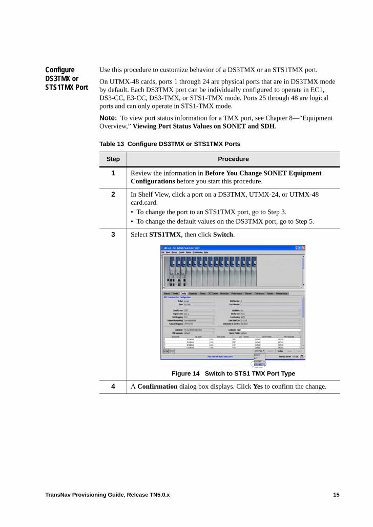
Configure DS3TMX or STS1TMX Port
Use this procedure to customize behavior of a DS3TMX or an STS1TMX port.
On UTMX-48 cards, ports 1 through 24 are physical ports that are in DS3TMX mode by default. Each DS3TMX port can be individually configured to operate in EC1, DS3-CC, E3-CC, DS3-TMX, or STS1-TMX mode. Ports 25 through 48 are logical ports and can only operate in STS1-TMX mode.
Note: To view port status information for a TMX port, see Chapter 8—“Equipment Overview,” Viewing Port Status Values on SONET and SDH.
Table 13 Configure DS3TMX or STS1TMX Ports
Step Procedure
1 Review the information in Before You Change SONET Equipment Configurations before you start this procedure.
2 In Shelf View, click a port on a DS3TMX, UTMX-24, or UTMX-48 card.card.• To change the port to an STS1TMX port, go to Step 3.• To change the default values on the DS3TMX port, go to Step 5.
3 Select STS1TMX, then click Switch.
Figure 14 Switch to STS1 TMX Port Type
4 A Confirmation dialog box displays. Click Yes to confirm the change.
TransNav Provisioning Guide, Release TN5.0.x 15
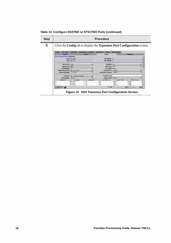
5 Click the Config tab to display the Transmux Port Configuration screen.
Figure 15 DS3 Transmux Port Configuration Screen
Table 13 Configure DS3TMX or STS1TMX Ports (continued)
Step Procedure
16 TransNav Provisioning Guide, Release TN5.0.x
6 Change any of the following parameters:
Line Format: Select one of the following:• M23: Seven DS2 signals asynchronously multiplexed into the DS3
signal.• CBIT (default): 28 DS-1 signals are multiplexed into the DS3 signal
with the C-bit used as control bit.
DS3 Mapping: Select the payload of the DS3 channelized signal:• DS1• E1
Subport Numbering: Select how the DS1 signals map into a VT payload on this port. See DS1 Numbering for a list of mapping formats. If this port is part of a protection group, this parameter must be the same on both cards. Select one of the following values: • Non-Sequential (default)• Sequential
Subport Mapping: Select the payload of the DS1 channels. Configurable only if DS3 Mapping is DS1.• VT1.5/VC11 (default): The DS1 channel is carried in a VT1.5 or VC11
payload. All 28 subports are available.• VT2/VC12: The DS1 channel is carried in a VT2 or VC12 payload.
Only the first 21 subports are available.
AIS Mask (Alarm Indication Signal Mask): Select one of the following:• Yes: Mask AIS/alarm for unused direction.• No (default): Do not mask AIS/alarm for any direction.
AIS Format: Select one of the following:• NAS (default): North America Standard. All C-bits shall be set to 0. All
X-bits shall be set to 1. The information bits shall be set to a 1010... repeating sequence, with a 1 immediately following each of the control bit positions.
• ONES: Unformatted all ones.
Line Build Out (DS3TMX only): Select the length of cable between the node and the intermediate patch panel from the following values:• 0 to 225 ft (default)• 255 to 450 ft
Table 13 Configure DS3TMX or STS1TMX Ports (continued)
Step Procedure
TransNav Provisioning Guide, Release TN5.0.x 17
Automatic In Service: (Available on Traverse node SONET services only.) Use to suppress the line level alarms and PM reports for ports that are not currently in service. Line level alarms and PM reports will be automatically initiated when the service is activated. The port must be unlocked to apply changes and monitor performance by generating alarms.• Enabled (default): Select to suppress the line level alarms and PM
reports for ports that are not currently in service.• Disabled: Select to report the line level alarms and PM reports for ports
that are not in service.
Note: Manually locking or unlocking the port will not affect the Automatic In Service parameter. The parameter must be set to Enabled to to suppress port line level alarms and PM reports.
7 Change any of the following general parameters for the interface:
Customer: Select from the list of defined customers.
PM Template (DS3TMX only): Select from the list of defined performance monitoring templates. Default value is default, which contains default thresholds for performance monitoring parameters and thresholds for DS3 ports.
Customer Tag: Enter an alphanumeric character string to identify the card to a customer.
Alarm Profile (DS3TMX only): Select from the list of defined alarm profiles (of type ds_ptp) to customize service-affecting and non-service-affecting alarm severities. Default is the default ds_ptp alarm profile.
8 Click the Lock icon to unlock the port. The port must be unlocked to apply changes and monitor performance by generating alarms. The Lock icon is located in the lower left corner of the screen.
9 Click Apply to save the changes.
10 The Configure DS3TMX or STS1TMX Port procedure is complete.
Table 13 Configure DS3TMX or STS1TMX Ports (continued)
Step Procedure
18 TransNav Provisioning Guide, Release TN5.0.x
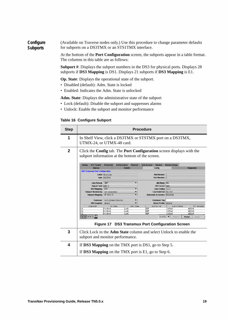
Configure Subports
(Available on Traverse nodes only.) Use this procedure to change parameter defaults for subports on a DS3TMX or an STS1TMX interface.
At the bottom of the Port Configuration screen, the subports appear in a table format. The columns in this table are as follows:
Subport #: Displays the subport numbers in the DS3 for physical ports. Displays 28 subports if DS3 Mapping is DS1. Displays 21 subports if DS3 Mapping is E1.
Op. State: Displays the operational state of the subport. • Disabled (default): Adm. State is locked• Enabled: Indicates the Adm. State is unlocked
Adm. State: Displays the administrative state of the subport• Lock (default): Disable the subport and suppresses alarms• Unlock: Enable the subport and monitor performance
Table 16 Configure Subport
Step Procedure
1 In Shelf View, click a DS3TMX or STSTMX port on a DS3TMX, UTMX-24, or UTMX-48 card.
2 Click the Config tab. The Port Configuration screen displays with the subport information at the bottom of the screen.
Figure 17 DS3 Transmux Port Configuration Screen
3 Click Lock in the Adm State column and select Unlock to enable the subport and monitor performance.
4 If DS3 Mapping on the TMX port is DS1, go to Step 5.
If DS3 Mapping on the TMX port is E1, go to Step 6.
TransNav Provisioning Guide, Release TN5.0.x 19

5 If DS3 Mapping on the TMX port is DS1, select one of the following values in the Line Format column:• ESF (default): Extended superframe format• SF: Superframe format• Unframed: Upon detecting an LOF condition (in Unframed mode), the
system does not:– Raise an LOF alarm– Propagate an AIS– Insert an RAI– Count OOF and SEF framing errors
6 If DS3 Mapping on the TMX port is E1, select one of the following values in the Line Format column:• Basic Frame: Select so the timing interface detects and generates the
Basic frame format per ITU-T Rec G.704/2.3 and G.706/4.1.2. This format does not support the SSM.
• Multi-Frame: Select so the timing interface detects and generates CRC-4 Multi-frame format per ITU-T Rec G.706/4.2. This format supports the SSM.
• Unframed: Select so that, upon detecting an LOF condition (in Unframed mode), the system does not:– Raise an LOF alarm– Propagate an AIS– Insert an RAI– Count OOF and SEF framing errors
7 Change any of the following general parameters for the interface:
Alarm Profile: Select from the list of defined alarm profiles (of type ds1_ptp) to customize service-affecting and non-service-affecting alarm severities.The default value is default, which is the default ds1_ptp alarm profile.
PM Template: Select from the list of defined performance monitoring templates (of type ds1_ptp_pm). Default value is default, which contains default thresholds for performance monitoring parameters and thresholds for DS1 ports.
8 Click Apply to save the changes.
9 The Configure Subports procedure is complete.
Table 16 Configure Subport (continued)
Step Procedure
20 TransNav Provisioning Guide, Release TN5.0.x
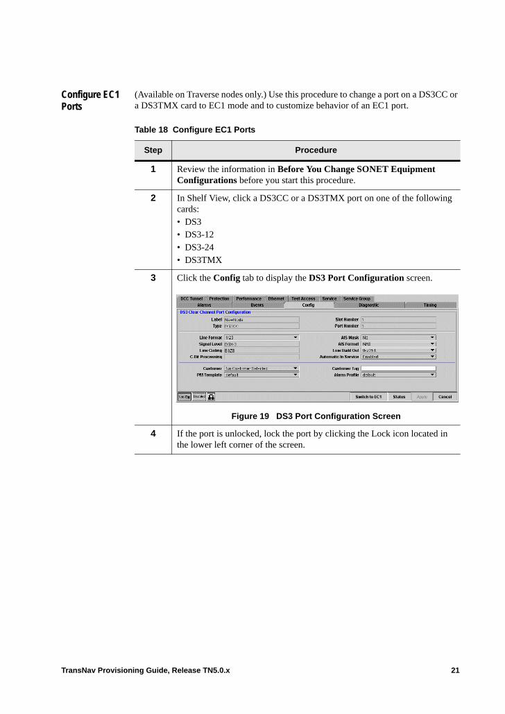
Configure EC1 Ports
(Available on Traverse nodes only.) Use this procedure to change a port on a DS3CC or a DS3TMX card to EC1 mode and to customize behavior of an EC1 port.
Table 18 Configure EC1 Ports
Step Procedure
1 Review the information in Before You Change SONET Equipment Configurations before you start this procedure.
2 In Shelf View, click a DS3CC or a DS3TMX port on one of the following cards:• DS3• DS3-12• DS3-24• DS3TMX
3 Click the Config tab to display the DS3 Port Configuration screen.
Figure 19 DS3 Port Configuration Screen
4 If the port is unlocked, lock the port by clicking the Lock icon located in the lower left corner of the screen.
TransNav Provisioning Guide, Release TN5.0.x 21
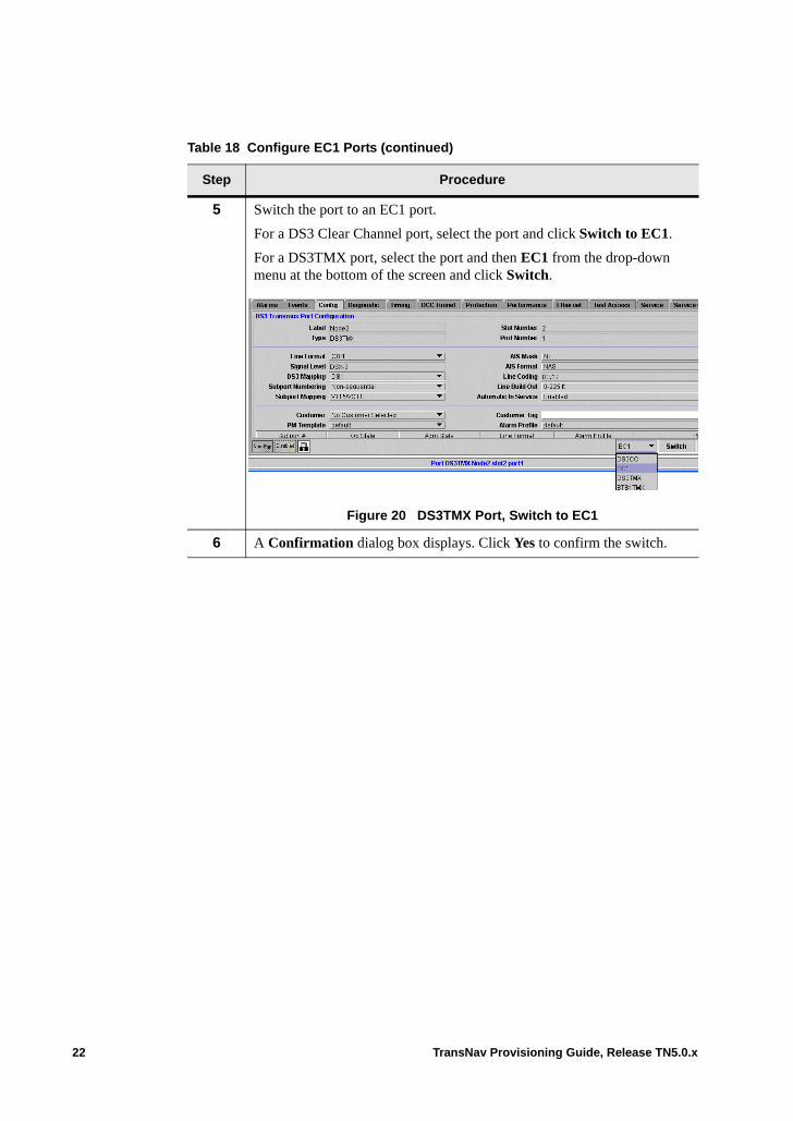
5 Switch the port to an EC1 port.
For a DS3 Clear Channel port, select the port and click Switch to EC1.
For a DS3TMX port, select the port and then EC1 from the drop-down menu at the bottom of the screen and click Switch.
Figure 20 DS3TMX Port, Switch to EC1
6 A Confirmation dialog box displays. Click Yes to confirm the switch.
Table 18 Configure EC1 Ports (continued)
Step Procedure
22 TransNav Provisioning Guide, Release TN5.0.x
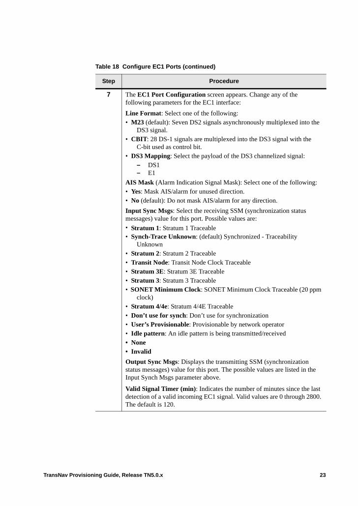
7 The EC1 Port Configuration screen appears. Change any of the following parameters for the EC1 interface:
Line Format: Select one of the following:• M23 (default): Seven DS2 signals asynchronously multiplexed into the
DS3 signal.• CBIT: 28 DS-1 signals are multiplexed into the DS3 signal with the
C-bit used as control bit.• DS3 Mapping: Select the payload of the DS3 channelized signal:
– DS1– E1
AIS Mask (Alarm Indication Signal Mask): Select one of the following:• Yes: Mask AIS/alarm for unused direction.• No (default): Do not mask AIS/alarm for any direction.
Input Sync Msgs: Select the receiving SSM (synchronization status messages) value for this port. Possible values are:• Stratum 1: Stratum 1 Traceable• Synch-Trace Unknown: (default) Synchronized - Traceability
Unknown• Stratum 2: Stratum 2 Traceable• Transit Node: Transit Node Clock Traceable• Stratum 3E: Stratum 3E Traceable• Stratum 3: Stratum 3 Traceable• SONET Minimum Clock: SONET Minimum Clock Traceable (20 ppm
clock)• Stratum 4/4e: Stratum 4/4E Traceable• Don’t use for synch: Don’t use for synchronization• User’s Provisionable: Provisionable by network operator• Idle pattern: An idle pattern is being transmitted/received• None• Invalid
Output Sync Msgs: Displays the transmitting SSM (synchronization status messages) value for this port. The possible values are listed in the Input Synch Msgs parameter above.
Valid Signal Timer (min): Indicates the number of minutes since the last detection of a valid incoming EC1 signal. Valid values are 0 through 2800. The default is 120.
Table 18 Configure EC1 Ports (continued)
Step Procedure
TransNav Provisioning Guide, Release TN5.0.x 23
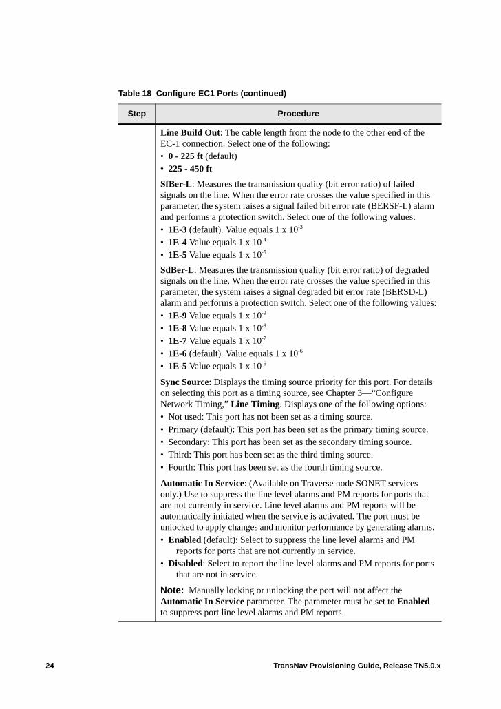
Line Build Out: The cable length from the node to the other end of the EC-1 connection. Select one of the following:• 0 - 225 ft (default)• 225 - 450 ft
SfBer-L: Measures the transmission quality (bit error ratio) of failed signals on the line. When the error rate crosses the value specified in this parameter, the system raises a signal failed bit error rate (BERSF-L) alarm and performs a protection switch. Select one of the following values: • 1E-3 (default). Value equals 1 x 10⁻³
• 1E-4 Value equals 1 x 10⁻⁴
• 1E-5 Value equals 1 x 10⁻⁵
SdBer-L: Measures the transmission quality (bit error ratio) of degraded signals on the line. When the error rate crosses the value specified in this parameter, the system raises a signal degraded bit error rate (BERSD-L) alarm and performs a protection switch. Select one of the following values:• 1E-9 Value equals 1 x 10⁻⁹
• 1E-8 Value equals 1 x 10⁻⁸
• 1E-7 Value equals 1 x 10⁻⁷
• 1E-6 (default). Value equals 1 x 10⁻⁶
• 1E-5 Value equals 1 x 10⁻⁵
Sync Source: Displays the timing source priority for this port. For details on selecting this port as a timing source, see Chapter 3—“Configure Network Timing,” Line Timing. Displays one of the following options:• Not used: This port has not been set as a timing source.• Primary (default): This port has been set as the primary timing source.• Secondary: This port has been set as the secondary timing source.• Third: This port has been set as the third timing source.• Fourth: This port has been set as the fourth timing source.
Automatic In Service: (Available on Traverse node SONET services only.) Use to suppress the line level alarms and PM reports for ports that are not currently in service. Line level alarms and PM reports will be automatically initiated when the service is activated. The port must be unlocked to apply changes and monitor performance by generating alarms. • Enabled (default): Select to suppress the line level alarms and PM
reports for ports that are not currently in service. • Disabled: Select to report the line level alarms and PM reports for ports
that are not in service.
Note: Manually locking or unlocking the port will not affect the Automatic In Service parameter. The parameter must be set to Enabled to suppress port line level alarms and PM reports.
Table 18 Configure EC1 Ports (continued)
Step Procedure
24 TransNav Provisioning Guide, Release TN5.0.x
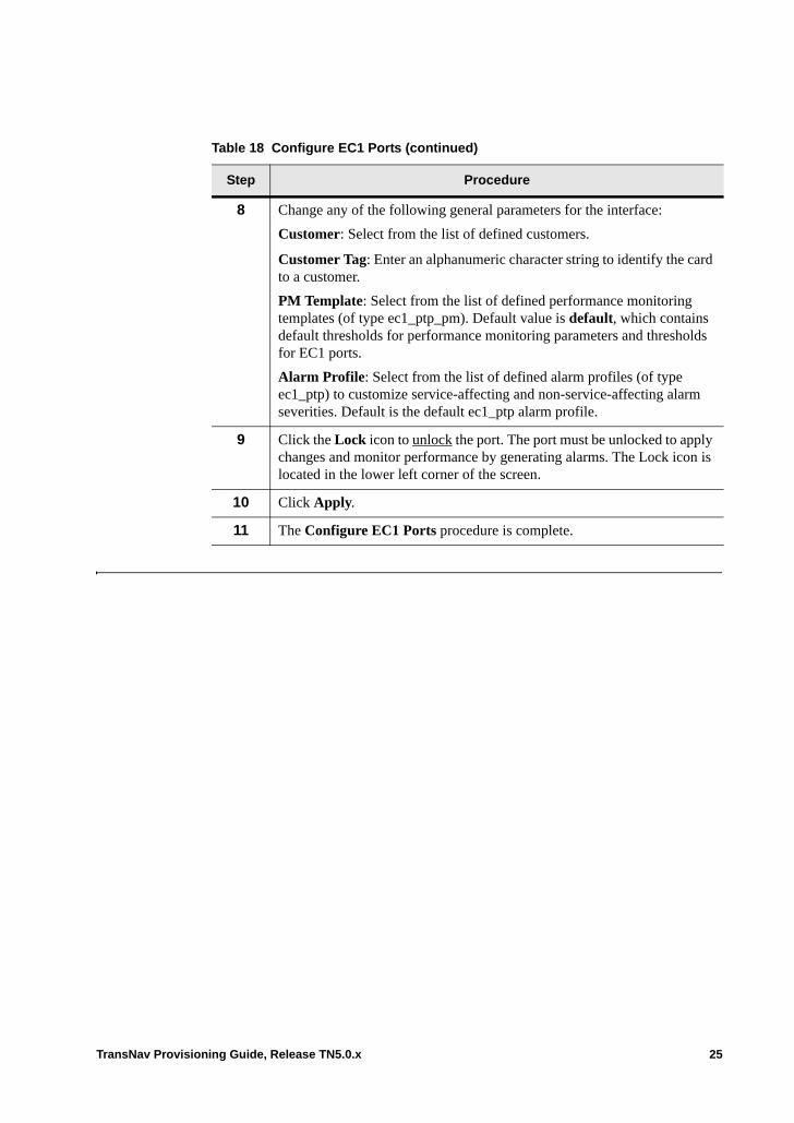
8 Change any of the following general parameters for the interface:
Customer: Select from the list of defined customers.
Customer Tag: Enter an alphanumeric character string to identify the card to a customer.
PM Template: Select from the list of defined performance monitoring templates (of type ec1_ptp_pm). Default value is default, which contains default thresholds for performance monitoring parameters and thresholds for EC1 ports.
Alarm Profile: Select from the list of defined alarm profiles (of type ec1_ptp) to customize service-affecting and non-service-affecting alarm severities. Default is the default ec1_ptp alarm profile.
9 Click the Lock icon to unlock the port. The port must be unlocked to apply changes and monitor performance by generating alarms. The Lock icon is located in the lower left corner of the screen.
10 Click Apply.
11 The Configure EC1 Ports procedure is complete.
Table 18 Configure EC1 Ports (continued)
Step Procedure
TransNav Provisioning Guide, Release TN5.0.x 25
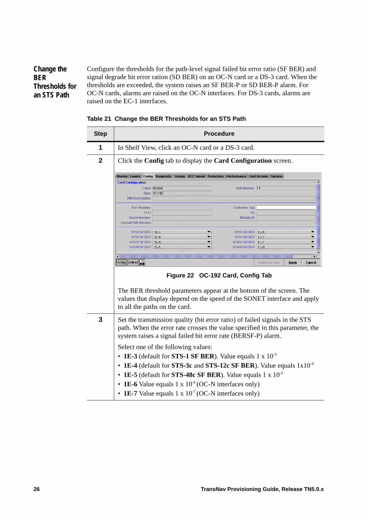
Change the BER Thresholds for an STS Path
Configure the thresholds for the path-level signal failed bit error ratio (SF BER) and signal degrade bit error ration (SD BER) on an OC-N card or a DS-3 card. When the thresholds are exceeded, the system raises an SF BER-P or SD BER-P alarm. For OC-N cards, alarms are raised on the OC-N interfaces. For DS-3 cards, alarms are raised on the EC-1 interfaces.
Table 21 Change the BER Thresholds for an STS Path
Step Procedure
1 In Shelf View, click an OC-N card or a DS-3 card.
2 Click the Config tab to display the Card Configuration screen.
Figure 22 OC-192 Card, Config Tab
The BER threshold parameters appear at the bottom of the screen. The values that display depend on the speed of the SONET interface and apply to all the paths on the card.
3 Set the transmission quality (bit error ratio) of failed signals in the STS path. When the error rate crosses the value specified in this parameter, the system raises a signal failed bit error rate (BERSF-P) alarm.
Select one of the following values:• 1E-3 (default for STS-1 SF BER). Value equals 1 x 10⁻³
• 1E-4 (default for STS-3c and STS-12c SF BER). Value equals 1x10⁻⁴
• 1E-5 (default for STS-48c SF BER). Value equals 1 x 10⁻⁵
• 1E-6 Value equals 1 x 10⁻⁶ (OC-N interfaces only)• 1E-7 Value equals 1 x 10⁻⁷ (OC-N interfaces only)
26 TransNav Provisioning Guide, Release TN5.0.x
4 Set the transmission quality (bit error ratio) of degraded signals (SD) in the STS path. When the error rate crosses the value specified in this parameter, the system raises a signal degraded bit error rate (BERSD-P) alarm. Select one of the following values:• 1E-4 Value equals 1 x 10⁻⁴ (OC-N interfaces only)• 1E-5 Value equals 1 x 10⁻⁵ • 1E-6 (default for STS-1 SD BER). Value equals 1 x 10⁻⁶
• 1E-7 (default for STS-3c and STS-12c SD BER). Value equals 1 x 10⁻⁷
• 1E-8 (default for STS-48c SD BER). Value equals 1 x 10⁻⁸
• 1E-9 Value equals 1 x 10⁻⁹
• 1E-10 Value equals 1 x 10⁻¹⁰ (OC-N interfaces only)• 1E-11 Value equals 1 x 10-11 (OC-N interfaces only)
5 Click Apply to save the changes.
6 The Change the BER Thresholds for an STS Path procedure is complete.
Table 21 Change the BER Thresholds for an STS Path (continued)
Step Procedure
TransNav Provisioning Guide, Release TN5.0.x 27
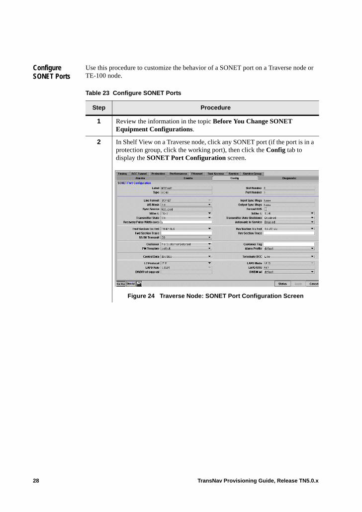
Configure SONET Ports
Use this procedure to customize the behavior of a SONET port on a Traverse node or TE-100 node.
Table 23 Configure SONET Ports
Step Procedure
1 Review the information in the topic Before You Change SONET Equipment Configurations.
2 In Shelf View on a Traverse node, click any SONET port (if the port is in a protection group, click the working port), then click the Config tab to display the SONET Port Configuration screen.
Figure 24 Traverse Node: SONET Port Configuration Screen
28 TransNav Provisioning Guide, Release TN5.0.x
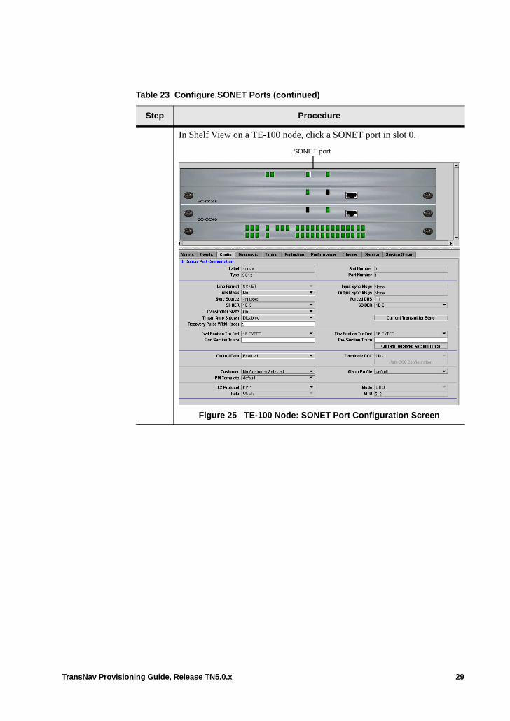
In Shelf View on a TE-100 node, click a SONET port in slot 0.
Figure 25 TE-100 Node: SONET Port Configuration Screen
Table 23 Configure SONET Ports (continued)
Step Procedure
SONET port
TransNav Provisioning Guide, Release TN5.0.x 29
3 Change any one of the following parameters for the SONET interface:
AIS Mask (Alarm Indication Signal Mask):• Yes: Mask AIS/alarm for unused direction.• No (default): Do not mask AIS/alarm for any direction.
Sync Source: Indicates if this port is used to synchronize timing status. Timing is restricted to a single port at any time for OC3 or STM1 cards. Valid values are:• Primary: Indicates this port is the primary timing source.• Secondary: Indicates this port is the secondary timing source.• Third: Indicates this port is the third timing source.• Fourth: Indicates this port is the fourth timing source.• Not used: Indicates this port is not used as the timing source.
For details on selecting this port as a timing source, see Chapter 3—“Configure Network Timing,” Reference List Options.
SfBer-L/SF BER: Measures the transmission quality (bit error ratio) of failed signals on the link. When the error rate crosses the value specified in this parameter, the system raises a signal failed bit error rate (BERSF-L) alarm and performs a protection switch. Select one of the following values: • 1E-3 (default). Value equals 1 x 10⁻³ • 1E-4 Value equals 1 x 10⁻⁴ • 1E-5 Value equals 1 x 10⁻⁵
Transmitter State: Select one of the following:• On (default): Laser is turned on.• Off: Laser is turned off.
Recovery Pulse Width (sec): The system enables the transmitter for the amount of time, in seconds, specified in this parameter. Valid only if the value in the Transmitter Auto Shutdown/Trnsm Auto Shtdwn parameter is Manual or Automatic. Enter a time between 2 and 10 seconds; the default is 5 seconds.
Table 23 Configure SONET Ports (continued)
Step Procedure
30 TransNav Provisioning Guide, Release TN5.0.x
Input Sync Msgs: Displays the receiving synchronization status messages (SSM) value for this port. Possible values are:• Stratum 1: Stratum 1 Traceable• Synch-Trace Unknown: Synchronized - Traceability Unknown• Stratum 2: Stratum 2 Traceable• Transit Node: Transit Node Clock Traceable• Stratum 3E: Stratum 3E Traceable• Stratum 3: Stratum 3 Traceable• SONET/SDH Minimum Clock: SONET Minimum Clock Traceable (20
ppm clock)• Stratum 4/4e: Stratum 4/4E Traceable• Don’t use for synch: Don’t use for synchronization (DUS)• User’s Provisionable: Provisionable by network operator• Idle pattern: An idle pattern is being transmitted/received
Output Sync Msgs: Displays the transmitting SSM (synchronization status messages) value for this port. Possible values are the same as for Input Synch Msgs parameter.
Forced DUS (Do not Use for Synchronization): Select for this port to transmit the SSM (synchronization status message) DUS. This prevents the remote node that receives this signal from using the line as a timing reference.
SdBer-L/SD BER: Measures the transmission quality (bit error ratio) of degraded signals on the optical link. When the error rate crosses the value specified in this parameter, the system raises a signal degraded bit error rate (BERSD-L) alarm and performs a protection switch. Select one of the following values: • 1E-9 Value equals 1 x 10⁻⁹
• 1E-8 Value equals 1 x 10⁻⁸
• 1E-7 Value equals 1 x 10⁻⁷
• 1E-6 (default). Value equals 1 x 10⁻⁶
• 1E-5 Value equals 1 x 10⁻⁵
Table 23 Configure SONET Ports (continued)
Step Procedure
TransNav Provisioning Guide, Release TN5.0.x 31
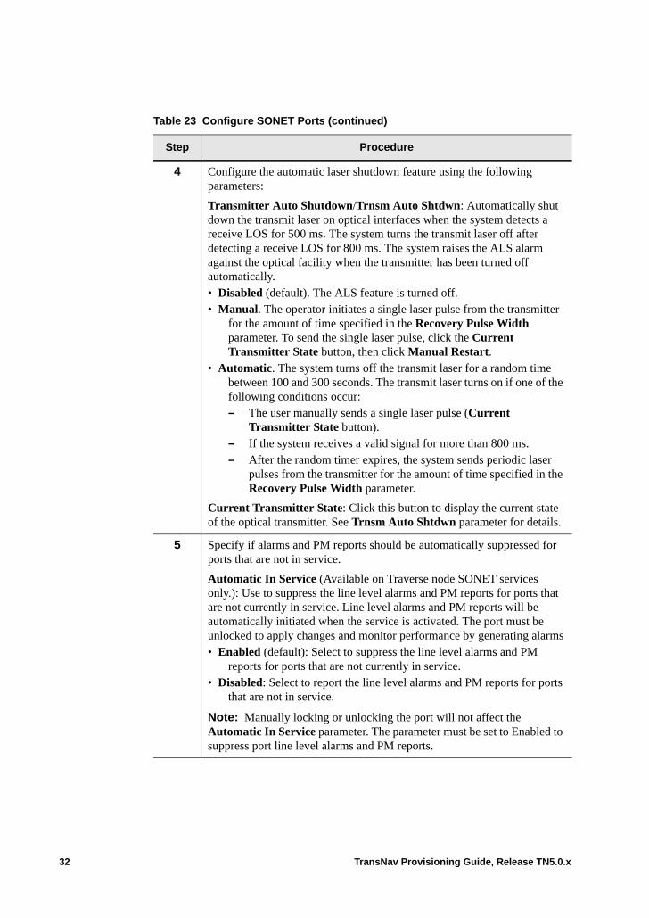
4 Configure the automatic laser shutdown feature using the following parameters:
Transmitter Auto Shutdown/Trnsm Auto Shtdwn: Automatically shut down the transmit laser on optical interfaces when the system detects a receive LOS for 500 ms. The system turns the transmit laser off after detecting a receive LOS for 800 ms. The system raises the ALS alarm against the optical facility when the transmitter has been turned off automatically.• Disabled (default). The ALS feature is turned off.• Manual. The operator initiates a single laser pulse from the transmitter
for the amount of time specified in the Recovery Pulse Width parameter. To send the single laser pulse, click the Current Transmitter State button, then click Manual Restart.
• Automatic. The system turns off the transmit laser for a random time between 100 and 300 seconds. The transmit laser turns on if one of the following conditions occur:– The user manually sends a single laser pulse (Current
Transmitter State button). – If the system receives a valid signal for more than 800 ms.– After the random timer expires, the system sends periodic laser
pulses from the transmitter for the amount of time specified in the Recovery Pulse Width parameter.
Current Transmitter State: Click this button to display the current state of the optical transmitter. See Trnsm Auto Shtdwn parameter for details.
5 Specify if alarms and PM reports should be automatically suppressed for ports that are not in service.
Automatic In Service (Available on Traverse node SONET services only.): Use to suppress the line level alarms and PM reports for ports that are not currently in service. Line level alarms and PM reports will be automatically initiated when the service is activated. The port must be unlocked to apply changes and monitor performance by generating alarms• Enabled (default): Select to suppress the line level alarms and PM
reports for ports that are not currently in service. • Disabled: Select to report the line level alarms and PM reports for ports
that are not in service.
Note: Manually locking or unlocking the port will not affect the Automatic In Service parameter. The parameter must be set to Enabled to suppress port line level alarms and PM reports.
Table 23 Configure SONET Ports (continued)
Step Procedure
32 TransNav Provisioning Guide, Release TN5.0.x
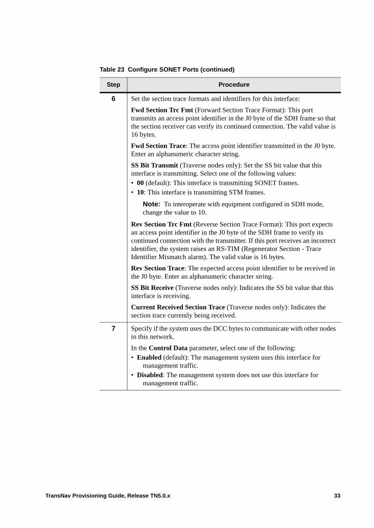
6 Set the section trace formats and identifiers for this interface:
Fwd Section Trc Fmt (Forward Section Trace Format): This port transmits an access point identifier in the J0 byte of the SDH frame so that the section receiver can verify its continued connection. The valid value is 16 bytes.
Fwd Section Trace: The access point identifier transmitted in the J0 byte. Enter an alphanumeric character string.
SS Bit Transmit (Traverse nodes only): Set the SS bit value that this interface is transmitting. Select one of the following values: • 00 (default): This interface is transmitting SONET frames.• 10: This interface is transmitting STM frames.
Note: To interoperate with equipment configured in SDH mode, change the value to 10.
Rev Section Trc Fmt (Reverse Section Trace Format): This port expects an access point identifier in the J0 byte of the SDH frame to verify its continued connection with the transmitter. If this port receives an incorrect identifier, the system raises an RS-TIM (Regenerator Section - Trace Identifier Mismatch alarm). The valid value is 16 bytes.
Rev Section Trace: The expected access point identifier to be received in the J0 byte. Enter an alphanumeric character string.
SS Bit Receive (Traverse nodes only): Indicates the SS bit value that this interface is receiving.
Current Received Section Trace (Traverse nodes only): Indicates the section trace currently being received.
7 Specify if the system uses the DCC bytes to communicate with other nodes in this network.
In the Control Data parameter, select one of the following:• Enabled (default): The management system uses this interface for
management traffic.• Disabled: The management system does not use this interface for
management traffic.
Table 23 Configure SONET Ports (continued)
Step Procedure
TransNav Provisioning Guide, Release TN5.0.x 33
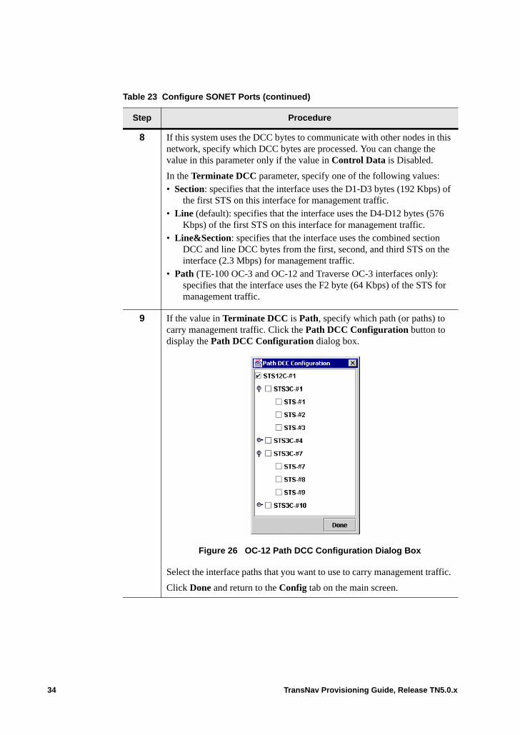
8 If this system uses the DCC bytes to communicate with other nodes in this network, specify which DCC bytes are processed. You can change the value in this parameter only if the value in Control Data is Disabled.
In the Terminate DCC parameter, specify one of the following values:• Section: specifies that the interface uses the D1-D3 bytes (192 Kbps) of
the first STS on this interface for management traffic. • Line (default): specifies that the interface uses the D4-D12 bytes (576
Kbps) of the first STS on this interface for management traffic. • Line&Section: specifies that the interface uses the combined section
DCC and line DCC bytes from the first, second, and third STS on the interface (2.3 Mbps) for management traffic.
• Path (TE-100 OC-3 and OC-12 and Traverse OC-3 interfaces only): specifies that the interface uses the F2 byte (64 Kbps) of the STS for management traffic.
9 If the value in Terminate DCC is Path, specify which path (or paths) to carry management traffic. Click the Path DCC Configuration button to display the Path DCC Configuration dialog box.
Figure 26 OC-12 Path DCC Configuration Dialog Box
Select the interface paths that you want to use to carry management traffic.
Click Done and return to the Config tab on the main screen.
Table 23 Configure SONET Ports (continued)
Step Procedure
34 TransNav Provisioning Guide, Release TN5.0.x
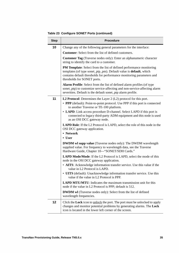
10 Change any of the following general parameters for the interface:
Customer: Select from the list of defined customers.
Customer Tag (Traverse nodes only): Enter an alphanumeric character string to identify the card to a customer.
PM Template: Select from the list of defined performance monitoring templates (of type sonet_ptp_pm). Default value is default, which contains default thresholds for performance monitoring parameters and thresholds for SONET ports.
Alarm Profile: Select from the list of defined alarm profiles (of type sonet_ptp) to customize service-affecting and non-service-affecting alarm severities. Default is the default sonet_ptp alarm profile.
11 L2 Protocol: Determines the Layer 2 (L2) protocol for this port. • PPP (default): Point-to-point protocol. Use PPP if this port is connected
to another Traverse or TE-100 platform.• LAPD: Link access procedure D-channel. Select LAPD if this port is
connected to legacy third-party ADM equipment and this node is used as an OSI DCC gateway node.
LAPD Role: If the L2 Protocol is LAPD, select the role of this node in the OSI DCC gateway application. • Network• User
DWDM wl supp value (Traverse nodes only): The DWDM wavelength supplied value. For frequency to wavelength data, see the Traverse Hardware Guide, Chapter 10—“SONET/SDH Cards.”
LAPD Mode/Mode: If the L2 Protocol is LAPD, select the mode of this node in the OSI DCC gateway application.• AITS: Acknowledge information transfer service. Use this value if the
value in L2 Protocol is LAPD.• UITS (default): Unacknowledge information transfer service. Use this
value if the value in L2 Protocol is PPP.
LAPD MTU/MTU: Indicates the maximum transmission unit for this node if the value in L2 Protocol is PPP; default is 512.
DWDM wl (Traverse nodes only): Select from the list of defined wavelength frequencies.
12 Click the Lock icon to unlock the port. The port must be unlocked to apply changes and monitor potential problems by generating alarms. The Lock icon is located in the lower left corner of the screen.
Table 23 Configure SONET Ports (continued)
Step Procedure
TransNav Provisioning Guide, Release TN5.0.x 35

SONET (OC-N) Card Parameters
On the Config tab for any SONET card, configure the point at which the system raises a path-level signal failed bit error rate (SFBER) or signal degraded bit error rate (SDBER) alarm.
Figure 27 OC-192 Card Parameters
These parameters appear depending on the speed of the SONET interface and apply to all the paths on the card.
STS-1 SF BER, STS-3c SF BER, STS-12c SF BER, and STS-48c SF BER: Measures the transmission quality of failed signals in the STS path. When the error rate crosses the value specified in this parameter, the system raises a signal failed bit error rate (BERSF-P) alarm. Select one of the following values:• 1E-3 (default for STS-1 SF BER): Value equals 1 x 10⁻³
• 1E-4 (default for STS-3c and STS-12c SF BER): Value equals 1 x 10⁻⁴
• 1E-5 (default for STS-48c SF BER): Value equals 1 x 10⁻⁵
STS-1 SD BER, STS-3c SD BER, STS-12c SD BER, and STS-48c SD BER: Measures the transmission quality of degraded signals in the STS path. When the error rate crosses the value specified in this parameter, the system raises a signal degraded bit error rate (BERSD-P) alarm. Select one of the following values:• 1E-5: Value equals 1 x 10⁻⁵
• 1E-6 (default for STS-1 SD BER): Value equals 1 x 10⁻⁶
• 1E-7 (default for STS-3c and STS-12c SD BER): Value equals 1 x 10⁻⁷
• 1E-8 (default for STS-48c SD BER): Value equals 1 x 10⁻⁸
• 1E-9: Value equals 1 x 10⁻⁹
13 Click Apply.
14 The Configure SONET Ports procedure is complete.
Table 23 Configure SONET Ports (continued)
Step Procedure
Configurable parameters
36 TransNav Provisioning Guide, Release TN5.0.x

• 1E-10: Value equals 1 x 10⁻¹⁰
• 1E-11: Value equals 1 x 10-11
FEC (OC-192 only): Forward error correction. Improves the link budget of this signal approximately 3 db. The resulting signal is no longer SONET/SDH compliant. Both ends of this link must have the same value in this parameter or the link will fail. • Enabled. Select to activate the FEC feature• Disabled (default)
SONET Port Parameters
From Shelf View, click a SONET port and click the Config tab. The SONET Port Configuration screen displays.
Figure 28 SONET Port Configuration Screen
The SONET Port Configuration screen allows you to view and set the following configuration information:
Label: Displays the node name
Type: Displays the port type (OC3, OC12, OC48, OC192)
Slot Number: Displays the slot number
Port Number: Displays the port number
Line Format: Displays SONET
AIS Mask (Alarm Indication Signal Mask):• Yes: Mask AIS/alarm for unused direction• No (default): Do not mask AIS/alarm for any direction
Sync Source: Displays the timing source priority for this port. For details on selecting this port as a timing source, see Chapter 2—“Timing,” Line Timing. Displays one of the following options:
TransNav Provisioning Guide, Release TN5.0.x 37

• Not used (default): This port has not been set as a timing source• Primary: This port has been set as the primary timing source• Secondary: This port has been set as the secondary timing source• Third: This port has been set as the third timing source• Fourth: This port has been set as the fourth timing source
Note: Timing is restricted to a single port at any time for OC3 or STM1 cards.
SfBer-L: Measures the transmission quality (bit error ratio) of failed signals on the link. When the error rate crosses the value specified in this parameter, the system raises a signal failed bit error rate (BERSF-L) alarm and performs a protection switch.
Select one of the following values: • 1E-3 (default): Value equals 1 x 10⁻³
• 1E-4: Value equals 1 x 10⁻⁴
• 1E-5: Value equals 1 x 10⁻⁵
Transmitter Auto Shutdown: Automatically shut down the transmit laser on optical interfaces when the system detects a receive LOS for 500 ms. The system turns the transmit laser off after detecting a receive LOS for 800 ms. The system raises the ALS alarm against the optical facility when the transmitter has been turned off automatically.• Disabled (default): The ALS feature is turned off.• Manual: The operator initiates a single laser pulse from the transmitter for the amount
of time specified in the Recovery Pulse Width parameter. To send the single laser pulse, click the Current Transmitter State button, then click Manual Restart.
• Automatic: The system turns off the transmit laser for a random time between 100 and 300 seconds. The transmit laser turns on if one of the following conditions occur:– The user manually sends a single laser pulse (Current Transmitter State
button).– If the system receives a valid signal for more than 800 ms.– After the random timer expires, the system sends periodic laser pulses from the
transmitter for the amount of time specified in the Recovery Pulse Width parameter.
Recovery Pulse Width: The system enables the transmitter for the amount of time specified in this parameter. Valid only if the value in Transmitter Auto Shutdown is Manual or Automatic. Enter a time between 2 and 10 seconds; default is 5 seconds.
Input Sync Msgs: Displays the receiving synchronization status messages (SSM) value for this port. Possible values are:• Stratum 1: Stratum 1 Traceable• Synch-Trace Unknown: Synchronized - Traceability Unknown• Stratum 2: Stratum 2 Traceable• Transit Node: Transit Node Clock Traceable• Stratum 3E: Stratum 3E Traceable• Stratum 3: Stratum 3 Traceable• SONET/SDH Minimum Clock: SONET Minimum Clock Traceable (20 ppm clock)
38 TransNav Provisioning Guide, Release TN5.0.x
• Stratum 4/4e: Stratum 4/4E Traceable• Don’t use for synch: Don’t use for synchronization (DUS)• User’s Provisionable: Provisionable by network operator• Idle pattern: An idle pattern is being transmitted/received
Output Sync Msgs: Displays the transmitting SSM (synchronization status messages) value for this port. Possible values are:• Stratum 1: Stratum 1 Traceable• Synch-Trace Unknown: Synchronized - Traceability Unknown• Stratum 2: Stratum 2 Traceable• Transit Node: Transit Node Clock Traceable• Stratum 3E: Stratum 3E Traceable• Stratum 3: Stratum 3 Traceable• SONET/SDH Minimum Clock: SONET Minimum Clock Traceable (20 ppm clock)• Stratum 4/4e: Stratum 4/4E Traceable• Don’t use for synch: Don’t use for synchronization• User’s Provisionable: Provisionable by network operator• Idle pattern: An idle pattern is being transmitted/received
Forced DUS (Do not Use for Synchronization): Select for this port to transmit the SSM (synchronization status message) DUS. This prevents the remote node that receives this signal from using the line as a timing reference.
SdBer-L: Measures the transmission quality (bit error ratio) of degraded signals on the optical link. When the error rate crosses the value specified in this parameter, the system raises a signal degraded bit error rate (BERSD-L) alarm and performs a protection switch. Select one of the following values: • 1E-9: Value equals 1 x 10⁻⁹
• 1E-8: Value equals 1 x 10⁻⁸
• 1E-7: Value equals 1 x 10⁻⁷
• 1E-6 (default): Value equals 1 x 10⁻⁶
• 1E-5: Value equals 1 x 10⁻⁵
Current Transmitter State: Click this button to display the current state of the optical transmitter. See the Transmitter Auto Shutdown parameter above for details.
Fwd Section Trc Fmt (Forward Section Trace Format): This port transmits an access point identifier in the J0 byte of the SONET frame so the section receiver can verify its continued connection. The valid value is 16 bytes.
Fwd Section Trace: The access point identifier transmitted in the J0 byte. Enter an alphanumeric character string.
SS Bit Transmit: Select the SS Bit value that this interface is transmitting: • 00 (default): This interface is transmitting SONET frames• 10: This interface is transmitting STM frames
Rev Section Trc Fmt (Reverse Section Trace Format): This port expects an access point identifier in the J0 byte of the SONET frame to verify its continued connection
TransNav Provisioning Guide, Release TN5.0.x 39
with the transmitter. If this port receives an incorrect identifier, the system raises an S-TIM (Section - Trace Identifier Mismatch alarm). The valid value is 16 bytes.
Current Received Section Trace: Indicates the section trace currently being received.
Customer: Select from the list of defined customer profiles. Default is No Customer Selected. For details on creating customer profiles, see Adding Customer Information.
PM Template: Select from the list of defined performance monitoring templates. Default is default, which contains default thresholds for performance monitoring parameters. The system default for performance monitoring thresholds is disabled for all parameters.
Use the performance monitoring templates to set default thresholds or to customize threshold values. See the Operations and Maintenance Guide, Chapter 4—“Managing Performance” for information on how to use performance monitoring templates and details on performance monitoring parameters for SONET ports.
Customer Tag: Enter an alphanumeric character string to identify the port to a customer.
Alarm Profile: Select from the list of defined alarm profiles. Default is default.
Control Data Indicates whether the management system uses the data communications channel (DCC) bytes on this SONET interface to communicate with other nodes. Select one of the following options:• Enabled (default for OC-12 and OC-48 ports): The management system uses this
interface for management traffic. • Disabled: The management system does not use this interface for management
traffic.
Terminate DCC: This parameter is specific to each SONET interface and specifies which DCC bytes to process. You can only change the value in this parameter if the value in Control Data is Disabled. Specify one of the following values:• Section: Specifies that the interface use the D1-D3 bytes (192 kbps) of the first STS
on this interface for management traffic.• Line (default): Specifies that the interface use the D4-D12 bytes (576 kbps) of the
first STS on this interface for management traffic.• Line&Section: Specifies that the interface uses the combined section DCC and line
DCC bytes from the first, second, and third STS on the interface (2.3 Mbps) for management traffic. This selection is available for Traverse to Traverse interworking only. It is unsupported for Traverse to TE-100 interworking.
Path DCC Configuration (TE-100 OC-3, and OC-12 interfaces only.): Click this button to configure the SONET paths to carry management traffic.
L2 Protocol: Determines the Layer 2 (L2) protocol for this port. • PPP (default): Point-to-point protocol. Use PPP if this port is connected to another
Traverse platform.• LAPD: Link access procedure D-channel. Select LAPD if this port is connected to
legacy third-party ADM equipment and this node is used as an OSI DCC gateway node.
40 TransNav Provisioning Guide, Release TN5.0.x
LAPD Role: Select the role of this node in the OSI DCC gateway application:• Network• User
DWDM wl supp value: The DWDM wavelength supplied value.
LAPD Mode: Select the mode of this node in the OSI DCC gateway application.• AITS: Acknowledge information transfer service. Use this value if the value in L2
Protocol is LAPD.• UITS (default): Unacknowledge information transfer service. Use this value if the
value in L2 Protocol is PPP.
LAPD MTU: Indicates the maximum transmission unit for this node if the value in L2 Protocol is PPP. Default is 512.
DWDM wl: Select from the list of defined wavelength frequencies. For frequency to wavelength data, see the Traverse Hardware Guide, Chapter 10—“SONET/SDH Cards.”
TransNav Provisioning Guide, Release TN5.0.x 41

42 TransNav Provisioning Guide, Release TN5.0.x
Chapter 11 Configuring SDH Equipment
Introduction This chapter explains how to change configurable parameters for the following types of ports in a Traverse shelf:• Before You Configure SDH Equipment• E1 Card Parameters• E1 Numbering (Traverse only)• E1 Mapping• E1 Mapping and Patch Panel Ports (Traverse only)• Change E1 Mapping Formats• Configure E1 Ports• Configure E3 Clear Channel Ports• Switching E1 Cards or Ports• Configure the BER Thresholds for an STM Path• Configure STM-N Port Parameters• SDH (STM) Card Parameters• STM Port Parameters• TE-100 Interface Card Parameters
These procedures describe how to change configurable parameters only.
To view the port status values, see Chapter 8—“Equipment Overview,” Viewing Port Status Values on SONET and SDH.
TransNav Provisioning Guide, Release TN5.0.x 1
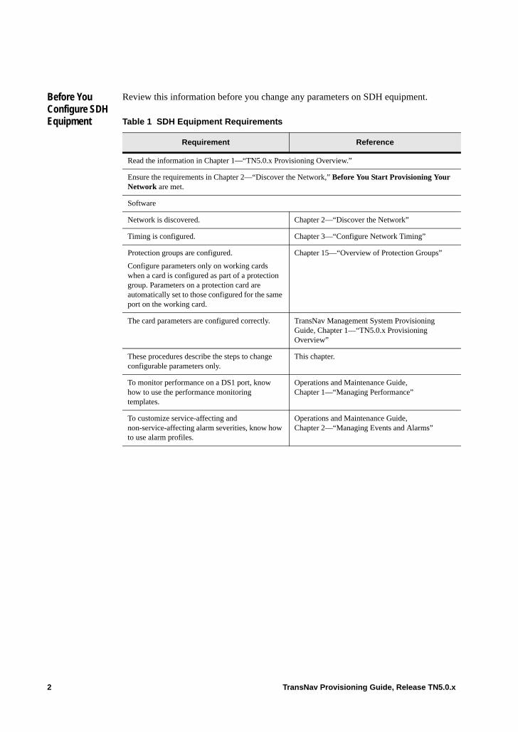
Before You Configure SDH Equipment
Review this information before you change any parameters on SDH equipment.
Table 1 SDH Equipment Requirements
Requirement Reference
Read the information in Chapter 1—“TN5.0.x Provisioning Overview.”
Ensure the requirements in Chapter 2—“Discover the Network,” Before You Start Provisioning Your Network are met.
Software
Network is discovered. Chapter 2—“Discover the Network”
Timing is configured. Chapter 3—“Configure Network Timing”
Protection groups are configured.
Configure parameters only on working cards when a card is configured as part of a protection group. Parameters on a protection card are automatically set to those configured for the same port on the working card.
Chapter 15—“Overview of Protection Groups”
The card parameters are configured correctly. TransNav Management System Provisioning Guide, Chapter 1—“TN5.0.x Provisioning Overview”
These procedures describe the steps to change configurable parameters only.
This chapter.
To monitor performance on a DS1 port, know how to use the performance monitoring templates.
Operations and Maintenance Guide, Chapter 1—“Managing Performance”
To customize service-affecting and non-service-affecting alarm severities, know how to use alarm profiles.
Operations and Maintenance Guide, Chapter 2—“Managing Events and Alarms”
2 TransNav Provisioning Guide, Release TN5.0.x
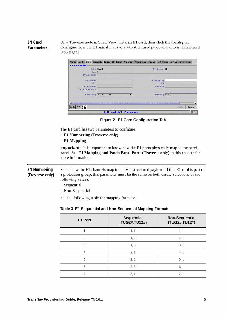
E1 Card Parameters
On a Traverse node in Shelf View, click an E1 card, then click the Config tab. Configure how the E1 signal maps to a VC-structured payload and to a channelized DS3 signal.
Figure 2 E1 Card Configuration Tab
The E1 card has two parameters to configure:• E1 Numbering (Traverse only)• E1 Mapping
Important: It is important to know how the E1 ports physically map to the patch panel. See E1 Mapping and Patch Panel Ports (Traverse only) in this chapter for more information.
E1 Numbering (Traverse only)
Select how the E1 channels map into a VC-structured payload. If this E1 card is part of a protection group, this parameter must be the same on both cards. Select one of the following values: • Sequential• Non-Sequential
See the following table for mapping formats:
Table 3 E1 Sequential and Non-Sequential Mapping Formats
E1 PortSequential
(TUG2#,TU12#)Non-Sequential(TUG2#,TU12#)
1 1, 1 1, 1
2 1, 2 2, 1
3 1, 3 3, 1
4 2, 1 4, 1
5 2, 2 5, 1
6 2, 3 6, 1
7 3, 1 7, 1
TransNav Provisioning Guide, Release TN5.0.x 3
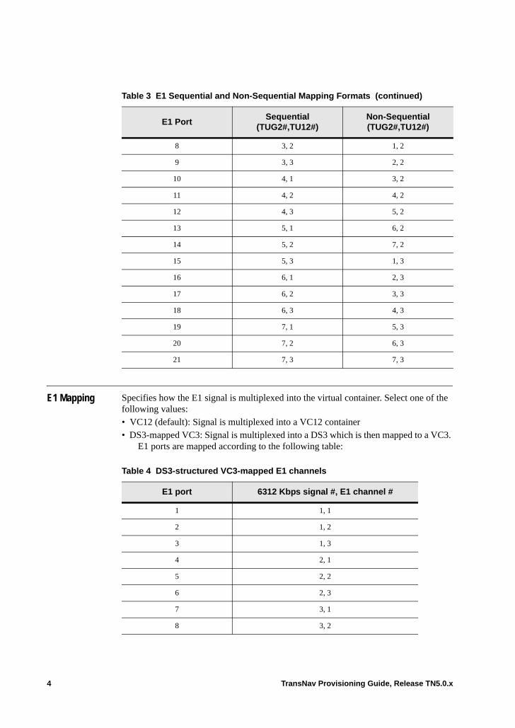
E1 Mapping Specifies how the E1 signal is multiplexed into the virtual container. Select one of the following values:• VC12 (default): Signal is multiplexed into a VC12 container• DS3-mapped VC3: Signal is multiplexed into a DS3 which is then mapped to a VC3.
E1 ports are mapped according to the following table:
8 3, 2 1, 2
9 3, 3 2, 2
10 4, 1 3, 2
11 4, 2 4, 2
12 4, 3 5, 2
13 5, 1 6, 2
14 5, 2 7, 2
15 5, 3 1, 3
16 6, 1 2, 3
17 6, 2 3, 3
18 6, 3 4, 3
19 7, 1 5, 3
20 7, 2 6, 3
21 7, 3 7, 3
Table 3 E1 Sequential and Non-Sequential Mapping Formats (continued)
E1 PortSequential
(TUG2#,TU12#)Non-Sequential(TUG2#,TU12#)
Table 4 DS3-structured VC3-mapped E1 channels
E1 port 6312 Kbps signal #, E1 channel #
1 1, 1
2 1, 2
3 1, 3
4 2, 1
5 2, 2
6 2, 3
7 3, 1
8 3, 2
4 TransNav Provisioning Guide, Release TN5.0.x
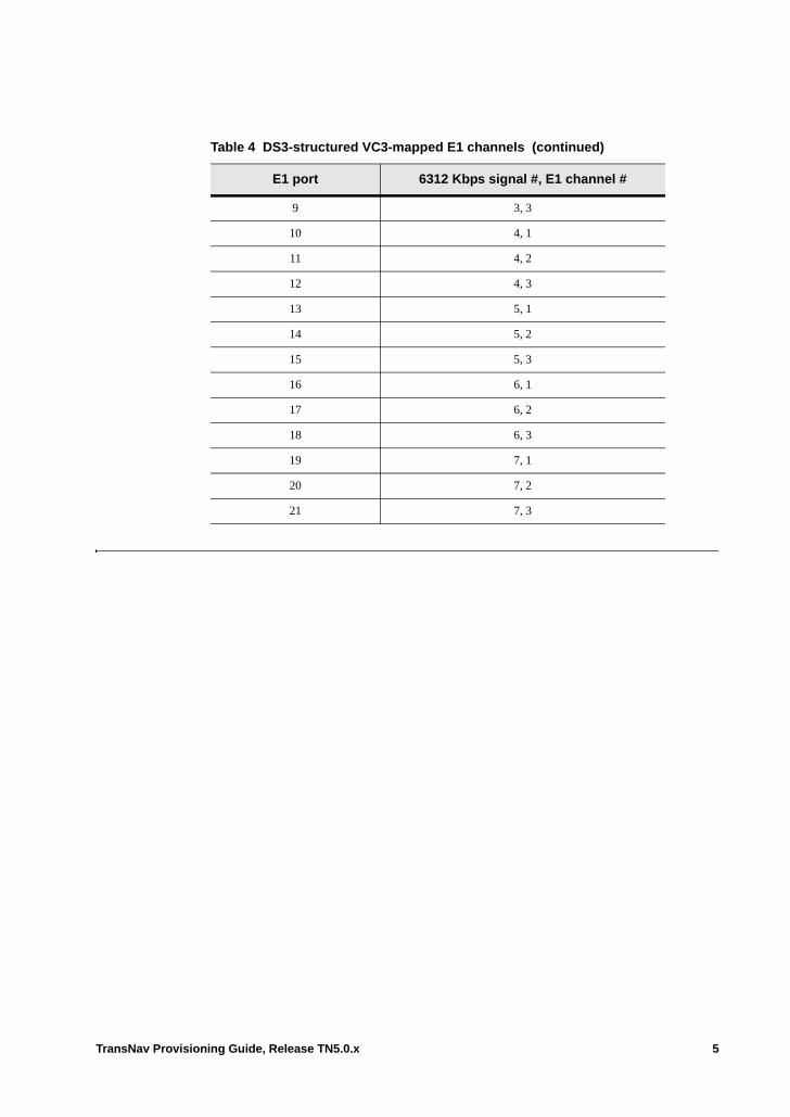
9 3, 3
10 4, 1
11 4, 2
12 4, 3
13 5, 1
14 5, 2
15 5, 3
16 6, 1
17 6, 2
18 6, 3
19 7, 1
20 7, 2
21 7, 3
Table 4 DS3-structured VC3-mapped E1 channels (continued)
E1 port 6312 Kbps signal #, E1 channel #
TransNav Provisioning Guide, Release TN5.0.x 5

E1 Mapping and Patch Panel Ports (Traverse only)
This table lists the relationship between the physical E1 port and the patch panel for E1 Mapping modes. .
Table 5 E1 Mapping and Patch Panel Ports
EI PortsPatch Panel Ports
DS3-Mapped VC12-Mapped
1 1 1
2 2 2
3 3 3
4 5 4
5 6 5
6 7 6
7 9 7
8 10 8
9 11 9
10 13 10
11 14 11
12 15 12
13 17 13
14 18 14
15 19 15
16 21 16
17 22 17
18 23 18
19 25 19
20 26 20
21 27 21
6 TransNav Provisioning Guide, Release TN5.0.x
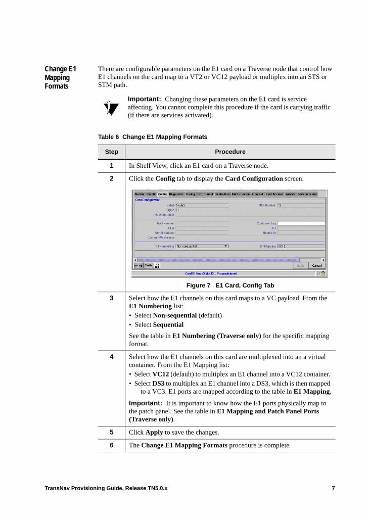
Change E1 Mapping Formats
There are configurable parameters on the E1 card on a Traverse node that control how E1 channels on the card map to a VT2 or VC12 payload or multiplex into an STS or STM path.
Important: Changing these parameters on the E1 card is service affecting. You cannot complete this procedure if the card is carrying traffic (if there are services activated).
Table 6 Change E1 Mapping Formats
Step Procedure
1 In Shelf View, click an E1 card on a Traverse node.
2 Click the Config tab to display the Card Configuration screen.
Figure 7 E1 Card, Config Tab
3 Select how the E1 channels on this card maps to a VC payload. From the E1 Numbering list: • Select Non-sequential (default)• Select Sequential
See the table in E1 Numbering (Traverse only) for the specific mapping format.
4 Select how the E1 channels on this card are multiplexed into an a virtual container. From the E1 Mapping list:• Select VC12 (default) to multiplex an E1 channel into a VC12 container. • Select DS3 to multiplex an E1 channel into a DS3, which is then mapped
to a VC3. E1 ports are mapped according to the table in E1 Mapping.
Important: It is important to know how the E1 ports physically map to the patch panel. See the table in E1 Mapping and Patch Panel Ports (Traverse only).
5 Click Apply to save the changes.
6 The Change E1 Mapping Formats procedure is complete.
TransNav Provisioning Guide, Release TN5.0.x 7

Configure E1 Ports
Use this procedure to customize behavior of an E1 port.
Table 8 Configure E1 Ports
Step Procedure
1 Review the information in the following sections:
For Traverse nodes: Before You Configure SDH Equipment
For TE-100 nodes: Before You Configure SDH Equipment.
2 For Shelf View on Traverse nodes, click an E1 port on an E1 card.
For Shelf View on TE-100 nodes, click an E1 port on the tributary card.
3 Click the Config tab to display the E1 Port Configuration screen.
Figure 9 E1 Port Configuration Screen
8 TransNav Provisioning Guide, Release TN5.0.x
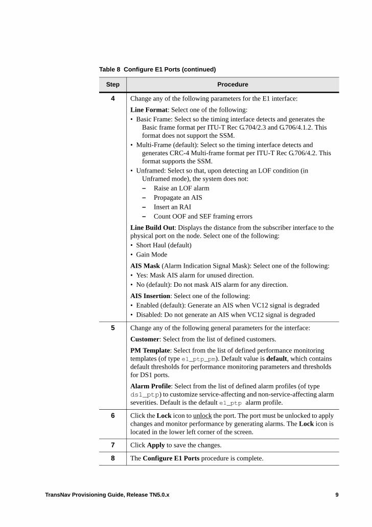
4 Change any of the following parameters for the E1 interface:
Line Format: Select one of the following:• Basic Frame: Select so the timing interface detects and generates the
Basic frame format per ITU-T Rec G.704/2.3 and G.706/4.1.2. This format does not support the SSM.
• Multi-Frame (default): Select so the timing interface detects and generates CRC-4 Multi-frame format per ITU-T Rec G.706/4.2. This format supports the SSM.
• Unframed: Select so that, upon detecting an LOF condition (in Unframed mode), the system does not:– Raise an LOF alarm– Propagate an AIS– Insert an RAI– Count OOF and SEF framing errors
Line Build Out: Displays the distance from the subscriber interface to the physical port on the node. Select one of the following:• Short Haul (default)• Gain Mode
AIS Mask (Alarm Indication Signal Mask): Select one of the following:• Yes: Mask AIS alarm for unused direction.• No (default): Do not mask AIS alarm for any direction.
AIS Insertion: Select one of the following:• Enabled (default): Generate an AIS when VC12 signal is degraded • Disabled: Do not generate an AIS when VC12 signal is degraded
5 Change any of the following general parameters for the interface:
Customer: Select from the list of defined customers.
PM Template: Select from the list of defined performance monitoring templates (of type e1_ptp_pm). Default value is default, which contains default thresholds for performance monitoring parameters and thresholds for DS1 ports.
Alarm Profile: Select from the list of defined alarm profiles (of type ds1_ptp) to customize service-affecting and non-service-affecting alarm severities. Default is the default e1_ptp alarm profile.
6 Click the Lock icon to unlock the port. The port must be unlocked to apply changes and monitor performance by generating alarms. The Lock icon is located in the lower left corner of the screen.
7 Click Apply to save the changes.
8 The Configure E1 Ports procedure is complete.
Table 8 Configure E1 Ports (continued)
Step Procedure
TransNav Provisioning Guide, Release TN5.0.x 9

Configure E3 Clear Channel Ports
Use this procedure to customize behavior of an E3-CC port.
Table 10 Configure E3CC Port
Step Procedure
1 Review the information in Before You Configure SDH Equipment.
2 For Shelf View on Traverse nodes, click an E3-CC port on a DS3/EC-1 / E3 card.
For Shelf View on TE-100 nodes, click an E3-CC port on the tributary card.
3 Click the Config tab to display the E3 Port Configuration screen.
Figure 11 E3 Port Configuration Screen
10 TransNav Provisioning Guide, Release TN5.0.x
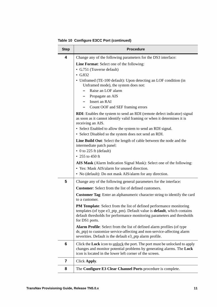
4 Change any of the following parameters for the DS3 interface:
Line Format: Select one of the following:• G.751 (Traverse default)• G.832• Unframed (TE-100 default): Upon detecting an LOF condition (in
Unframed mode), the system does not:– Raise an LOF alarm– Propagate an AIS– Insert an RAI– Count OOF and SEF framing errors
RDI: Enables the system to send an RDI (remote defect indicator) signal as soon as it cannot identify valid framing or when it determines it is receiving an AIS.• Select Enabled to allow the system to send an RDI signal.• Select Disabled so the system does not send an RDI.
Line Build Out: Select the length of cable between the node and the intermediate patch panel:• 0 to 225 ft (default)• 255 to 450 ft
AIS Mask (Alarm Indication Signal Mask): Select one of the following:• Yes: Mask AIS/alarm for unused direction.• No (default): Do not mask AIS/alarm for any direction.
5 Change any of the following general parameters for the interface:
Customer: Select from the list of defined customers.
Customer Tag: Enter an alphanumeric character string to identify the card to a customer.
PM Template: Select from the list of defined performance monitoring templates (of type e3_ptp_pm). Default value is default, which contains default thresholds for performance monitoring parameters and thresholds for DS1 ports.
Alarm Profile: Select from the list of defined alarm profiles (of type ds_ptp) to customize service-affecting and non-service-affecting alarm severities. Default is the default e3_ptp alarm profile.
6 Click the Lock icon to unlock the port. The port must be unlocked to apply changes and monitor potential problems by generating alarms. The Lock icon is located in the lower left corner of the screen.
7 Click Apply.
8 The Configure E3 Clear Channel Ports procedure is complete.
Table 10 Configure E3CC Port (continued)
Step Procedure
TransNav Provisioning Guide, Release TN5.0.x 11
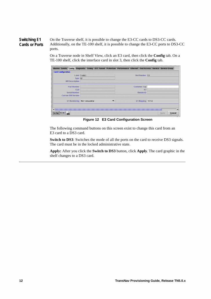
Switching E1 Cards or Ports
On the Traverse shelf, it is possible to change the E3-CC cards to DS3-CC cards. Additionally, on the TE-100 shelf, it is possible to change the E3-CC ports to DS3-CC ports.
On a Traverse node in Shelf View, click an E3 card, then click the Config tab. On a TE-100 shelf, click the interface card in slot 3, then click the Config tab.
Figure 12 E3 Card Configuration Screen
The following command buttons on this screen exist to change this card from an E3 card to a DS3 card.
Switch to DS3: Switches the mode of all the ports on the card to receive DS3 signals. The card must be in the locked administrative state.
Apply: After you click the Switch to DS3 button, click Apply. The card graphic in the shelf changes to a DS3 card.
12 TransNav Provisioning Guide, Release TN5.0.x
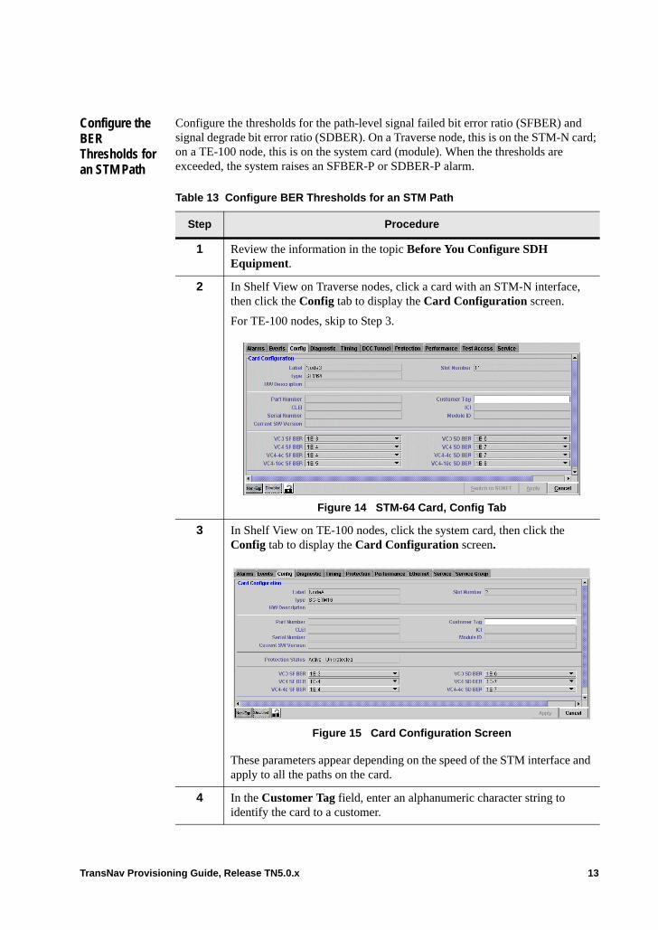
Configure the BER Thresholds for an STM Path
Configure the thresholds for the path-level signal failed bit error ratio (SFBER) and signal degrade bit error ratio (SDBER). On a Traverse node, this is on the STM-N card; on a TE-100 node, this is on the system card (module). When the thresholds are exceeded, the system raises an SFBER-P or SDBER-P alarm.
Table 13 Configure BER Thresholds for an STM Path
Step Procedure
1 Review the information in the topic Before You Configure SDH Equipment.
2 In Shelf View on Traverse nodes, click a card with an STM-N interface, then click the Config tab to display the Card Configuration screen.
For TE-100 nodes, skip to Step 3.
Figure 14 STM-64 Card, Config Tab
3 In Shelf View on TE-100 nodes, click the system card, then click the Config tab to display the Card Configuration screen.
Figure 15 Card Configuration Screen
These parameters appear depending on the speed of the STM interface and apply to all the paths on the card.
4 In the Customer Tag field, enter an alphanumeric character string to identify the card to a customer.
TransNav Provisioning Guide, Release TN5.0.x 13
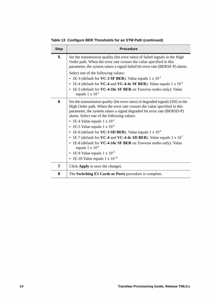
5 Set the transmission quality (bit error ratio) of failed signals in the High Order path. When the error rate crosses the value specified in this parameter, the system raises a signal failed bit error rate (BERSF-P) alarm.
Select one of the following values:• 1E-3 (default for VC-3 SF BER): Value equals 1 x 10⁻³
• 1E-4 (default for VC-4 and VC-4-4c SF BER): Value equals 1 x 10⁻⁴
• 1E-5 (default for VC-4-16c SF BER on Traverse nodes only): Value equals 1 x 10⁻⁵
6 Set the transmission quality (bit error ratio) of degraded signals (SD) in the High Order path. When the error rate crosses the value specified in this parameter, the system raises a signal degraded bit error rate (BERSD-P) alarm. Select one of the following values:• 1E-4 Value equals 1 x 10⁻⁴
• 1E-5 Value equals 1 x 10⁻⁵
• 1E-6 (default for VC-3 SD BER). Value equals 1 x 10⁻⁶
• 1E-7 (default for VC-4 and VC-4-4c SD BER). Value equals 1 x 10⁻⁷
• 1E-8 (default for VC-4-16c SF BER on Traverse nodes only). Value equals 1 x 10⁻⁸
• 1E-9 Value equals 1 x 10⁻⁹
• 1E-10 Value equals 1 x 10⁻¹⁰
7 Click Apply to save the changes.
8 The Switching E1 Cards or Ports procedure is complete.
Table 13 Configure BER Thresholds for an STM Path (continued)
Step Procedure
14 TransNav Provisioning Guide, Release TN5.0.x
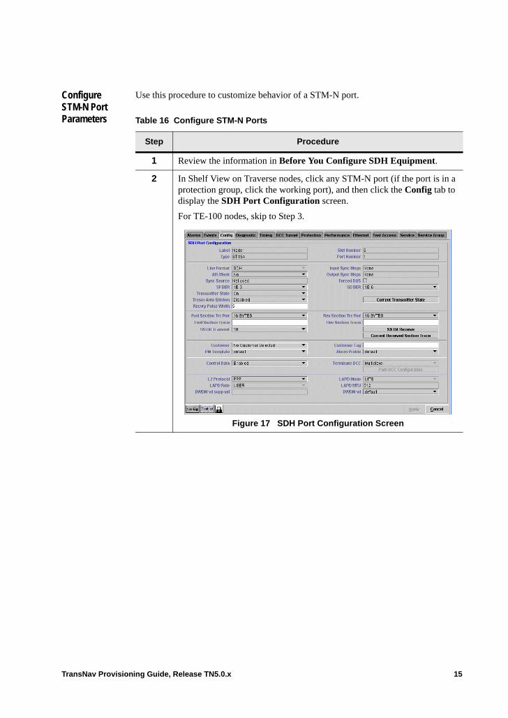
Configure STM-N Port Parameters
Use this procedure to customize behavior of a STM-N port.
Table 16 Configure STM-N Ports
Step Procedure
1 Review the information in Before You Configure SDH Equipment.
2 In Shelf View on Traverse nodes, click any STM-N port (if the port is in a protection group, click the working port), and then click the Config tab to display the SDH Port Configuration screen.
For TE-100 nodes, skip to Step 3.
Figure 17 SDH Port Configuration Screen
TransNav Provisioning Guide, Release TN5.0.x 15
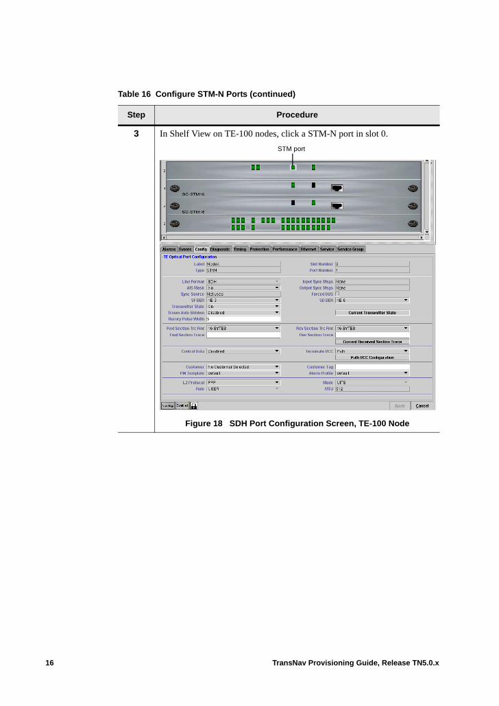
3 In Shelf View on TE-100 nodes, click a STM-N port in slot 0.
Figure 18 SDH Port Configuration Screen, TE-100 Node
Table 16 Configure STM-N Ports (continued)
Step Procedure
STM port
16 TransNav Provisioning Guide, Release TN5.0.x
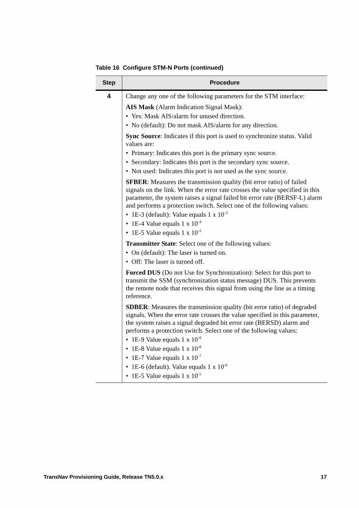
4 Change any one of the following parameters for the STM interface:
AIS Mask (Alarm Indication Signal Mask):• Yes: Mask AIS/alarm for unused direction.• No (default): Do not mask AIS/alarm for any direction.
Sync Source: Indicates if this port is used to synchronize status. Valid values are:• Primary: Indicates this port is the primary sync source.• Secondary: Indicates this port is the secondary sync source.• Not used: Indicates this port is not used as the sync source.
SFBER: Measures the transmission quality (bit error ratio) of failed signals on the link. When the error rate crosses the value specified in this parameter, the system raises a signal failed bit error rate (BERSF-L) alarm and performs a protection switch. Select one of the following values: • 1E-3 (default): Value equals 1 x 10⁻³
• 1E-4 Value equals 1 x 10⁻⁴ • 1E-5 Value equals 1 x 10⁻⁵
Transmitter State: Select one of the following values:• On (default): The laser is turned on.• Off: The laser is turned off.
Forced DUS (Do not Use for Synchronization): Select for this port to transmit the SSM (synchronization status message) DUS. This prevents the remote node that receives this signal from using the line as a timing reference.
SDBER: Measures the transmission quality (bit error ratio) of degraded signals. When the error rate crosses the value specified in this parameter, the system raises a signal degraded bit error rate (BERSD) alarm and performs a protection switch. Select one of the following values: • 1E-9 Value equals 1 x 10⁻⁹
• 1E-8 Value equals 1 x 10⁻⁸
• 1E-7 Value equals 1 x 10⁻⁷
• 1E-6 (default). Value equals 1 x 10⁻⁶
• 1E-5 Value equals 1 x 10⁻⁵
Table 16 Configure STM-N Ports (continued)
Step Procedure
TransNav Provisioning Guide, Release TN5.0.x 17
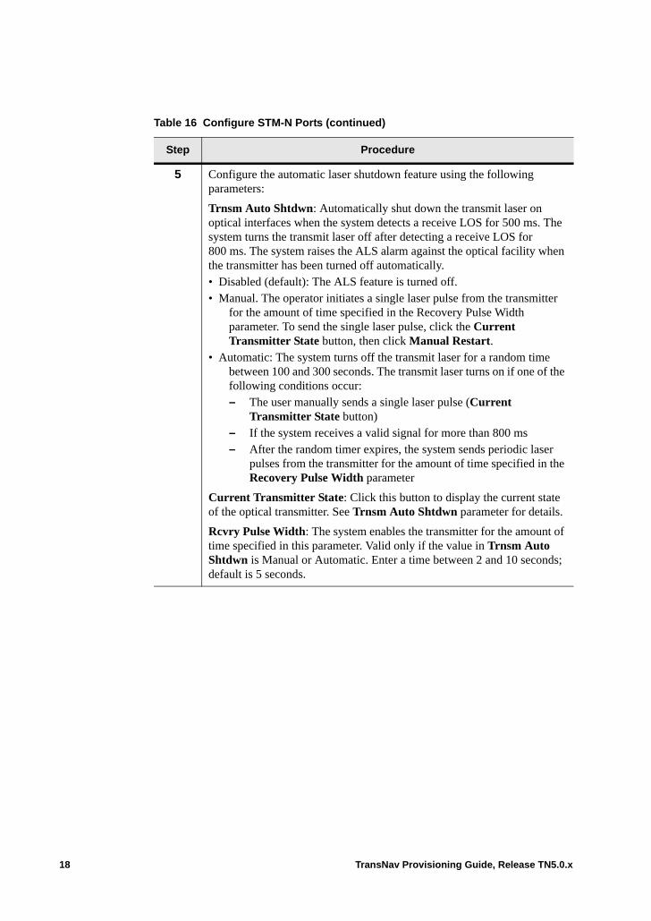
5 Configure the automatic laser shutdown feature using the following parameters:
Trnsm Auto Shtdwn: Automatically shut down the transmit laser on optical interfaces when the system detects a receive LOS for 500 ms. The system turns the transmit laser off after detecting a receive LOS for 800 ms. The system raises the ALS alarm against the optical facility when the transmitter has been turned off automatically.• Disabled (default): The ALS feature is turned off.• Manual. The operator initiates a single laser pulse from the transmitter
for the amount of time specified in the Recovery Pulse Width parameter. To send the single laser pulse, click the Current Transmitter State button, then click Manual Restart.
• Automatic: The system turns off the transmit laser for a random time between 100 and 300 seconds. The transmit laser turns on if one of the following conditions occur:– The user manually sends a single laser pulse (Current
Transmitter State button)– If the system receives a valid signal for more than 800 ms– After the random timer expires, the system sends periodic laser
pulses from the transmitter for the amount of time specified in the Recovery Pulse Width parameter
Current Transmitter State: Click this button to display the current state of the optical transmitter. See Trnsm Auto Shtdwn parameter for details.
Rcvry Pulse Width: The system enables the transmitter for the amount of time specified in this parameter. Valid only if the value in Trnsm Auto Shtdwn is Manual or Automatic. Enter a time between 2 and 10 seconds; default is 5 seconds.
Table 16 Configure STM-N Ports (continued)
Step Procedure
18 TransNav Provisioning Guide, Release TN5.0.x

6 Set the section trace formats and identifiers for this interface:
Fwd Section Trc Fmt (Forward Section Trace Format): This port transmits an access point identifier in the J0 byte of the SDH frame so that the section receiver can verify its continued connection. The valid value is 16 bytes.
Fwd Section Trace: The access point identifier transmitted in the J0 byte. Enter an alphanumeric character string.
SS Bit Transmit (Traverse nodes only): Set the SS bit value that this interface is transmitting. Set one of the following values:• 00: This interface is transmitting SONET frames.• 10 (default): This interface is transmitting STM frames.
Note: To interoperate with equipment configured in SONET mode, change the value to 00.
Rev Section Trc Fmt (Reverse Section Trace Format): This port expects an access point identifier in the J0 byte of the SDH frame to verify its continued connection with the transmitter. If this port receives an incorrect identifier, the system raises an RS-TIM (Regenerator Section - Trace Identifier Mismatch alarm). The valid value is 16 bytes.
Rev Section Trace: The expected access point identifier to be received in the J0 byte. Enter an alphanumeric character string.
SS Bit Receive (Traverse nodes only):: Indicates the SS bit value that this in terface is receiving.
Current Received Section Trace (Traverse nodes only):: Indicates the section trace currently being received.
7 Specify if the system uses the DCC bytes to communicate with other nodes in this network.
In the Control Data parameter, select one of the following:• Enabled (default): The management system uses this interface for
management traffic.• Disabled: The management system does not use this interface for
management traffic.
Table 16 Configure STM-N Ports (continued)
Step Procedure
TransNav Provisioning Guide, Release TN5.0.x 19
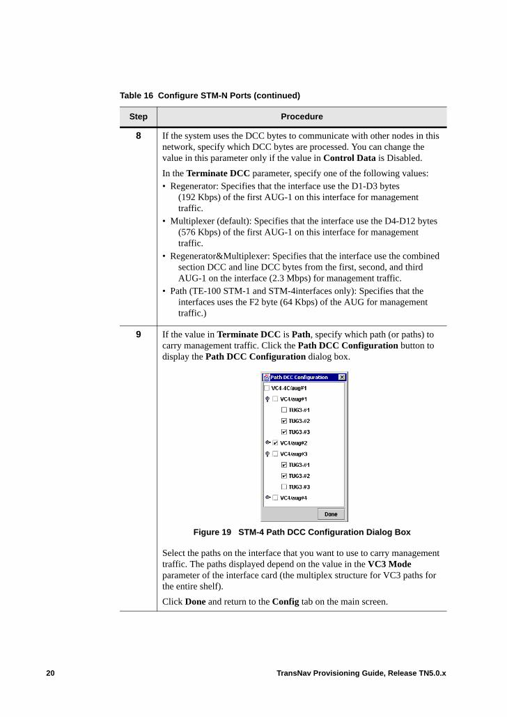
8 If the system uses the DCC bytes to communicate with other nodes in this network, specify which DCC bytes are processed. You can change the value in this parameter only if the value in Control Data is Disabled.
In the Terminate DCC parameter, specify one of the following values:• Regenerator: Specifies that the interface use the D1-D3 bytes
(192 Kbps) of the first AUG-1 on this interface for management traffic.
• Multiplexer (default): Specifies that the interface use the D4-D12 bytes (576 Kbps) of the first AUG-1 on this interface for management traffic.
• Regenerator&Multiplexer: Specifies that the interface use the combined section DCC and line DCC bytes from the first, second, and third AUG-1 on the interface (2.3 Mbps) for management traffic.
• Path (TE-100 STM-1 and STM-4interfaces only): Specifies that the interfaces uses the F2 byte (64 Kbps) of the AUG for management traffic.)
9 If the value in Terminate DCC is Path, specify which path (or paths) to carry management traffic. Click the Path DCC Configuration button to display the Path DCC Configuration dialog box.
Figure 19 STM-4 Path DCC Configuration Dialog Box
Select the paths on the interface that you want to use to carry management traffic. The paths displayed depend on the value in the VC3 Mode parameter of the interface card (the multiplex structure for VC3 paths for the entire shelf).
Click Done and return to the Config tab on the main screen.
Table 16 Configure STM-N Ports (continued)
Step Procedure
20 TransNav Provisioning Guide, Release TN5.0.x
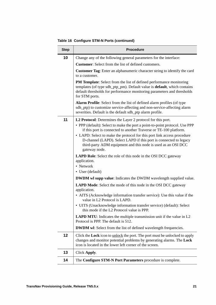
10 Change any of the following general parameters for the interface:
Customer: Select from the list of defined customers.
Customer Tag: Enter an alphanumeric character string to identify the card to a customer.
PM Template: Select from the list of defined performance monitoring templates (of type sdh_ptp_pm). Default value is default, which contains default thresholds for performance monitoring parameters and thresholds for STM ports.
Alarm Profile: Select from the list of defined alarm profiles (of type sdh_ptp) to customize service-affecting and non-service-affecting alarm severities. Default is the default sdh_ptp alarm profile.
11 L2 Protocol: Determines the Layer 2 protocol for this port. • PPP (default): Select to make the port a point-to-point protocol. Use PPP
if this port is connected to another Traverse or TE-100 platform.• LAPD: Select to make the protocol for this port link access procedure
D-channel (LAPD). Select LAPD if this port is connected to legacy third-party ADM equipment and this node is used as an OSI DCC gateway node.
LAPD Role: Select the role of this node in the OSI DCC gateway application.• Network• User (default)
DWDM wl supp value: Indicates the DWDM wavelength supplied value.
LAPD Mode: Select the mode of this node in the OSI DCC gateway application.• AITS (Acknowledge information transfer service): Use this value if the
value in L2 Protocol is LAPD.• UITS (Unacknowledge information transfer service) (default): Select
this mode if the L2 Protocol value is PPP.
LAPD MTU: Indicates the multiple transmission unit if the value in L2 Protocol is PPP. The default is 512.
DWDM wl: Select from the list of defined wavelength frequencies.
12 Click the Lock icon to unlock the port. The port must be unlocked to apply changes and monitor potential problems by generating alarms. The Lock icon is located in the lower left corner of the screen.
13 Click Apply.
14 The Configure STM-N Port Parameters procedure is complete.
Table 16 Configure STM-N Ports (continued)
Step Procedure
TransNav Provisioning Guide, Release TN5.0.x 21
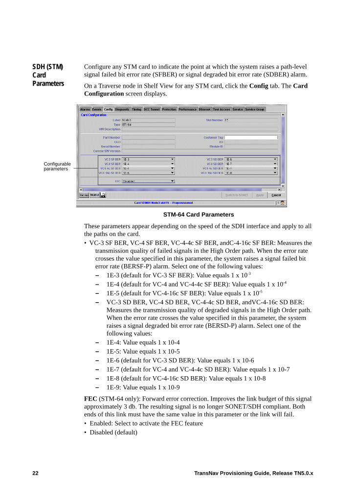
SDH (STM) Card Parameters
Configure any STM card to indicate the point at which the system raises a path-level signal failed bit error rate (SFBER) or signal degraded bit error rate (SDBER) alarm.
On a Traverse node in Shelf View for any STM card, click the Config tab. The Card Configuration screen displays.
STM-64 Card Parameters
These parameters appear depending on the speed of the SDH interface and apply to all the paths on the card.• VC-3 SF BER, VC-4 SF BER, VC-4-4c SF BER, andC-4-16c SF BER: Measures the
transmission quality of failed signals in the High Order path. When the error rate crosses the value specified in this parameter, the system raises a signal failed bit error rate (BERSF-P) alarm. Select one of the following values:– 1E-3 (default for VC-3 SF BER): Value equals 1 x 10⁻³
– 1E-4 (default for VC-4 and VC-4-4c SF BER): Value equals 1 x 10⁻⁴ – 1E-5 (default for VC-4-16c SF BER): Value equals 1 x 10⁻⁵ – VC-3 SD BER, VC-4 SD BER, VC-4-4c SD BER, andVC-4-16c SD BER:
Measures the transmission quality of degraded signals in the High Order path. When the error rate crosses the value specified in this parameter, the system raises a signal degraded bit error rate (BERSD-P) alarm. Select one of the following values:
– 1E-4: Value equals 1 x 10⁻⁴– 1E-5: Value equals 1 x 10⁻⁵ – 1E-6 (default for VC-3 SD BER): Value equals 1 x 10⁻⁶– 1E-7 (default for VC-4 and VC-4-4c SD BER): Value equals 1 x 10⁻⁷– 1E-8 (default for VC-4-16c SD BER): Value equals 1 x 10⁻⁸– 1E-9: Value equals 1 x 10⁻⁹
FEC (STM-64 only): Forward error correction. Improves the link budget of this signal approximately 3 db. The resulting signal is no longer SONET/SDH compliant. Both ends of this link must have the same value in this parameter or the link will fail. • Enabled: Select to activate the FEC feature• Disabled (default)
Configurable parameters
22 TransNav Provisioning Guide, Release TN5.0.x
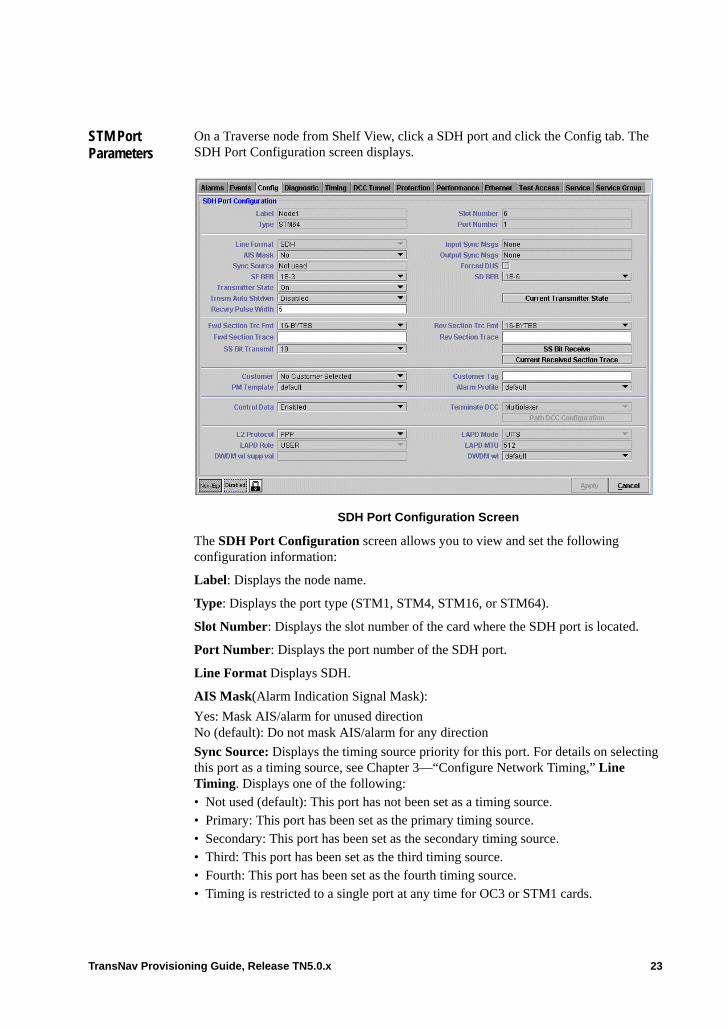
STM Port Parameters
On a Traverse node from Shelf View, click a SDH port and click the Config tab. The SDH Port Configuration screen displays.
SDH Port Configuration Screen
The SDH Port Configuration screen allows you to view and set the following configuration information:
Label: Displays the node name.
Type: Displays the port type (STM1, STM4, STM16, or STM64).
Slot Number: Displays the slot number of the card where the SDH port is located.
Port Number: Displays the port number of the SDH port.
Line Format Displays SDH.
AIS Mask(Alarm Indication Signal Mask):
Yes: Mask AIS/alarm for unused directionNo (default): Do not mask AIS/alarm for any direction
Sync Source: Displays the timing source priority for this port. For details on selecting this port as a timing source, see Chapter 3—“Configure Network Timing,” Line Timing. Displays one of the following:• Not used (default): This port has not been set as a timing source.• Primary: This port has been set as the primary timing source.• Secondary: This port has been set as the secondary timing source.• Third: This port has been set as the third timing source.• Fourth: This port has been set as the fourth timing source.• Timing is restricted to a single port at any time for OC3 or STM1 cards.
TransNav Provisioning Guide, Release TN5.0.x 23
SF BER: Measures the transmission quality (bit error ratio) of failed signals on the link. When the error rate crosses the value specified in this parameter, the system raises a signal failed bit error rate (BERSF-L) alarm and performs a protection switch. Select one of the following values: • 1E-3 (default): Value equals 1 x 10⁻³
• 1E-4: Value equals 1 x 10⁻⁴
• 1E-5: Value equals 1 x 10⁻⁵
Transmitter State: Select one of the following:• On (default): Transmit laser is turned on.• Off: Transmit laser is turned off.
Transmitter Auto Shutdown: Automatically shut down the transmit laser on optical interfaces when the system detects a receive LOS for 500 ms. The system turns the transmit laser off after detecting a receive LOS for 800 ms. The system raises the ALS alarm against the optical facility when the transmitter has been turned off automatically.• Disabled (default): The ALS feature is turned off.• Manual: The operator initiates a single laser pulse from the transmitter for the amount
of time specified in the Recovery Pulse Width parameter. To send the single laser pulse, click the urrent Transmitter State button, then click Manual Restart.
• Automatic: The system turns off the transmit laser for a random time between 100 and 300 seconds. The transmit laser turns on if one of the following conditions occur:The user manually sends a single laser pulse (Current Transmitter State button) If the system receives a valid signal for more than 800 msAfter the random timer expires, the system sends periodic laser pulses from the transmitter for the amount of time specified in the Recovery Pulse Width parameter
Recovery Pulse Width: The system enables the transmitter for the amount of time specified in this parameter. Valid only if the value in Transmitter Auto Shutdown is Manual or Automatic. Enter a time between 2 and 10 seconds; the default is 5 seconds.
Input Sync Msgs: Displays the receiving synchronization status messages (SSM) value for this port. Possible values are:• Stratum 1: Stratum 1 Traceable• Synch-Trace Unknown: Synchronized - Traceability Unknown• Stratum 2: Stratum 2 Traceable• Transit Node: Transit Node Clock Traceable• Stratum 3E: Stratum 3E Traceable• Stratum 3: Stratum 3 Traceable• SONET/SDH Minimum Clock: SONET Minimum Clock Traceable (20 ppm clock)• Stratum 4/4e: Stratum 4/4E Traceable• Don’t use for synch: Don’t use for synchronization• User’s Provisionable: Provisionable by network operator• Idle pattern: An idle pattern is being transmitted/received
24 TransNav Provisioning Guide, Release TN5.0.x
Output Sync Msgs: Displays the transmitting SSM (synchronization status messages) value for this port. Possible values are:• Stratum 1: Stratum 1 Traceable• Synch-Trace Unknown: Synchronized - Traceability Unknown• Stratum 2: Stratum 2 Traceable• Transit Node: Transit Node Clock Traceable• Stratum 3E: Stratum 3E Traceable• Stratum 3: Stratum 3 Traceable• SONET/SDH Minimum Clock: SONET Minimum Clock Traceable (20 ppm clock)• Stratum 4/4e: Stratum 4/4E Traceable• Don’t use for synch: Don’t use for synchronization• User’s Provisionable: Provisionable by network operator• Idle pattern: An idle pattern is being transmitted/received
Forced DUS: Do not Use for Synchronization): Select for this port to transmit the SSM (synchronization status message) DUS. This prevents the remote node that receives this signal from using the line as a timing reference.
SD BER: Measures the transmission quality (bit error ratio) of degraded signals on the optical link. When the error rate crosses the value specified in this parameter, the system raises a signal degraded bit error rate (BERSD-L) alarm and performs a protection switch. Select one of the following values: • 1E-9: Value equals 1 x 10⁻⁹
• 1E-8: Value equals 1 x 10⁻⁸
• 1E-7: Value equals 1 x 10⁻⁷
• 1E-6 (default): Value equals 1 x 10⁻⁶
• 1E-5: Value equals 1 x 10⁻⁵
Fwd Section Trc Fmt (Forward Section Trace Format): This port transmits an access point identifier in the J0 byte of the SDH frame so that the section receiver can verify its continued connection. The valid value is 16 bytes.
Fwd Section Trace: The access point identifier transmitted in the J0 byte. Enter an alphanumeric character string.
SS Bit Transmit: Select the SS bit value that this interface is transmitting: • 00: This interface is transmitting SONET frames.• 10 (default): This interface is transmitting STM frames.
Rev Section Trc Fmt (Reverse Section Trace Format): This port expects an access point identifier in the J0 byte of the SDH frame to verify its continued connection with the transmitter. If this port receives an incorrect identifier, the system raises an RS-TIM (Regenerator Section - Trace Identifier Mismatch alarm). The valid value is 16 bytes.
Current Received Section Trace: Indicates the section trace currently being received.
Customer: Select from the list of defined customer profiles. Default is No Customer Selected. For details on creating customer profiles, see Adding Customer Information.
TransNav Provisioning Guide, Release TN5.0.x 25
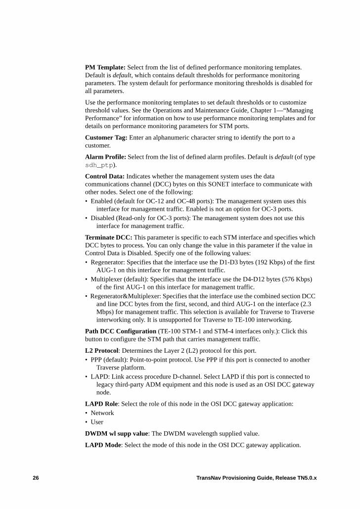
PM Template: Select from the list of defined performance monitoring templates. Default is default, which contains default thresholds for performance monitoring parameters. The system default for performance monitoring thresholds is disabled for all parameters.
Use the performance monitoring templates to set default thresholds or to customize threshold values. See the Operations and Maintenance Guide, Chapter 1—“Managing Performance” for information on how to use performance monitoring templates and for details on performance monitoring parameters for STM ports.
Customer Tag: Enter an alphanumeric character string to identify the port to a customer.
Alarm Profile: Select from the list of defined alarm profiles. Default is default (of type sdh_ptp).
Control Data: Indicates whether the management system uses the data communications channel (DCC) bytes on this SONET interface to communicate with other nodes. Select one of the following:• Enabled (default for OC-12 and OC-48 ports): The management system uses this
interface for management traffic. Enabled is not an option for OC-3 ports.• Disabled (Read-only for OC-3 ports): The management system does not use this
interface for management traffic.
Terminate DCC: This parameter is specific to each STM interface and specifies which DCC bytes to process. You can only change the value in this parameter if the value in Control Data is Disabled. Specify one of the following values:• Regenerator: Specifies that the interface use the D1-D3 bytes (192 Kbps) of the first
AUG-1 on this interface for management traffic.• Multiplexer (default): Specifies that the interface use the D4-D12 bytes (576 Kbps)
of the first AUG-1 on this interface for management traffic.• Regenerator&Multiplexer: Specifies that the interface use the combined section DCC
and line DCC bytes from the first, second, and third AUG-1 on the interface (2.3 Mbps) for management traffic. This selection is available for Traverse to Traverse interworking only. It is unsupported for Traverse to TE-100 interworking.
Path DCC Configuration (TE-100 STM-1 and STM-4 interfaces only.): Click this button to configure the STM path that carries management traffic.
L2 Protocol: Determines the Layer 2 (L2) protocol for this port. • PPP (default): Point-to-point protocol. Use PPP if this port is connected to another
Traverse platform.• LAPD: Link access procedure D-channel. Select LAPD if this port is connected to
legacy third-party ADM equipment and this node is used as an OSI DCC gateway node.
LAPD Role: Select the role of this node in the OSI DCC gateway application:• Network• User
DWDM wl supp value: The DWDM wavelength supplied value.
LAPD Mode: Select the mode of this node in the OSI DCC gateway application.
26 TransNav Provisioning Guide, Release TN5.0.x
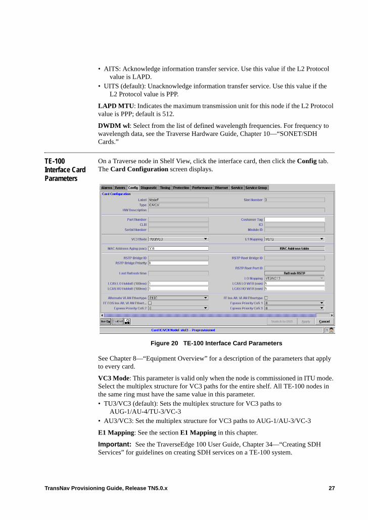
• AITS: Acknowledge information transfer service. Use this value if the L2 Protocol value is LAPD.
• UITS (default): Unacknowledge information transfer service. Use this value if the L2 Protocol value is PPP.
LAPD MTU: Indicates the maximum transmission unit for this node if the L2 Protocol value is PPP; default is 512.
DWDM wl: Select from the list of defined wavelength frequencies. For frequency to wavelength data, see the Traverse Hardware Guide, Chapter 10—“SONET/SDH Cards.”
TE-100 Interface Card Parameters
On a Traverse node in Shelf View, click the interface card, then click the Config tab. The Card Configuration screen displays.
Figure 20 TE-100 Interface Card Parameters
See Chapter 8—“Equipment Overview” for a description of the parameters that apply to every card.
VC3 Mode: This parameter is valid only when the node is commissioned in ITU mode. Select the multiplex structure for VC3 paths for the entire shelf. All TE-100 nodes in the same ring must have the same value in this parameter.• TU3/VC3 (default): Sets the multiplex structure for VC3 paths to
AUG-1/AU-4/TU-3/VC-3• AU3/VC3: Set the multiplex structure for VC3 paths to AUG-1/AU-3/VC-3
E1 Mapping: See the section E1 Mapping in this chapter.
Important: See the TraverseEdge 100 User Guide, Chapter 34—“Creating SDH Services” for guidelines on creating SDH services on a TE-100 system.
TransNav Provisioning Guide, Release TN5.0.x 27

For all other parameters on the Interface Card, see Chapter 12—“Configuring Ethernet Equipment.”
28 TransNav Provisioning Guide, Release TN5.0.x
Chapter 12 Configuring Ethernet Equipment
Introduction This chapter contains the topics listed below. These procedures describe how to change the following configurable parameters on Traverse and TE-100 nodes only. • Before You Begin• Configure Ethernet Cards• Configure Ethernet Port Parameter Values• Link OAM on an Ethernet Port• Configuring Link OAM on an Ethernet Port
– LOAM Interoperability with Traverse Equipment– LOAM Status Information for Local and Peer Entity PortsAuto
Negotiation– Configure Auto Negotiation
• View the SFP / XFP Port Parameters• View the Diagnostic Parameters• View the Negotiated Status of a Link• View or Edit the MAC Address Table• Ethernet or EOS Port Queues
See Chapter 10—“Configuring SONET Equipment” and Chapter 11—“Configuring SDH Equipment” in this guide for explanations of all the parameters and fields on each card (module).
VLAN Tagging can be configured on Traverse and TE-100 nodes. For information on configuring VLAN tagging, see Chapter 50—“VLAN Tagging on Traverse Ethernet Services.”
The customer uses the 3-bit priority field to indicate the quality of service the packet receives in relation to other packets on the same data stream. These priority bits are used to set the internal class of service and the initial drop precedence for this packet. See Chapter 53—“Classifying and Prioritizing Packets.”
TransNav Provisioning Guide, Release TN5.0.x 1
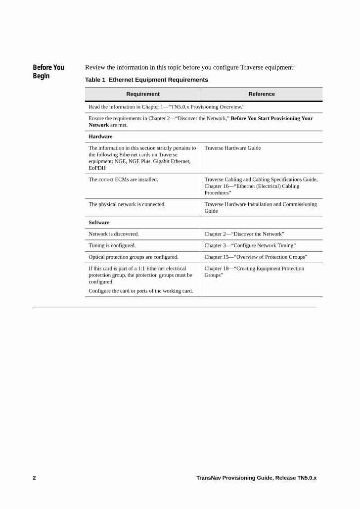
Before You Begin
Review the information in this topic before you configure Traverse equipment:
Table 1 Ethernet Equipment Requirements
Requirement Reference
Read the information in Chapter 1—“TN5.0.x Provisioning Overview.”
Ensure the requirements in Chapter 2—“Discover the Network,” Before You Start Provisioning Your Network are met.
Hardware
The information in this section strictly pertains to the following Ethernet cards on Traverse equipment: NGE, NGE Plus, Gigabit Ethernet, EoPDH
Traverse Hardware Guide
The correct ECMs are installed. Traverse Cabling and Cabling Specifications Guide, Chapter 16—“Ethernet (Electrical) Cabling Procedures”
The physical network is connected. Traverse Hardware Installation and Commissioning Guide
Software
Network is discovered. Chapter 2—“Discover the Network”
Timing is configured. Chapter 3—“Configure Network Timing”
Optical protection groups are configured. Chapter 15—“Overview of Protection Groups”
If this card is part of a 1:1 Ethernet electrical protection group, the protection groups must be configured.
Configure the card or ports of the working card.
Chapter 18—“Creating Equipment Protection Groups”
2 TransNav Provisioning Guide, Release TN5.0.x
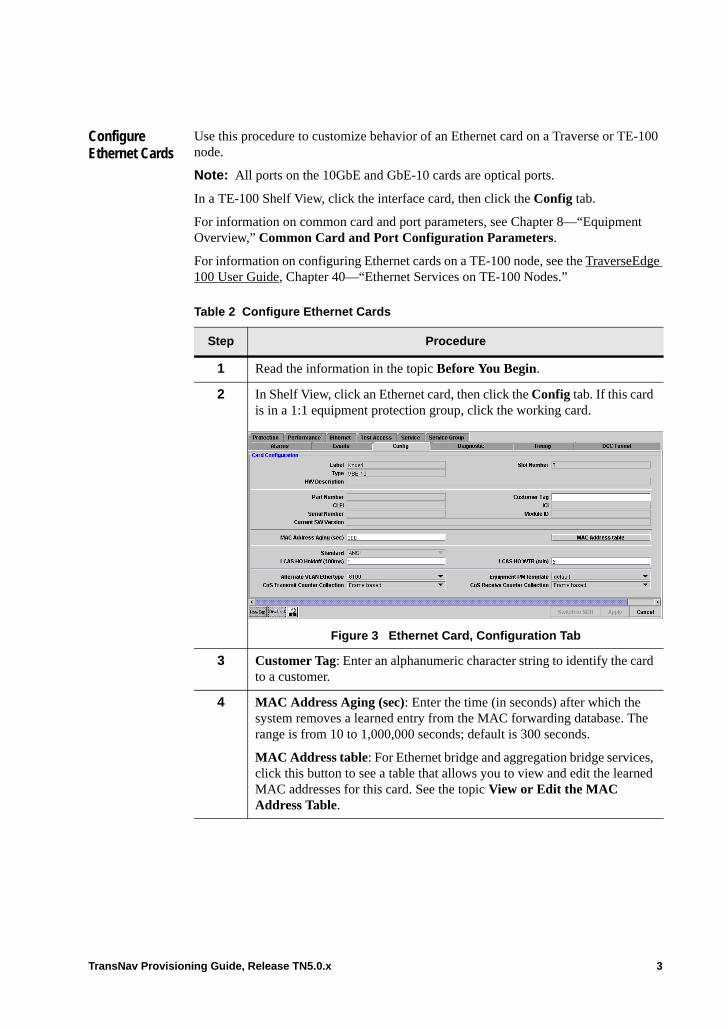
Configure Ethernet Cards
Use this procedure to customize behavior of an Ethernet card on a Traverse or TE-100 node.
Note: All ports on the 10GbE and GbE-10 cards are optical ports.
In a TE-100 Shelf View, click the interface card, then click the Config tab.
For information on common card and port parameters, see Chapter 8—“Equipment Overview,” Common Card and Port Configuration Parameters.
For information on configuring Ethernet cards on a TE-100 node, see the TraverseEdge 100 User Guide, Chapter 40—“Ethernet Services on TE-100 Nodes.”
Table 2 Configure Ethernet Cards
Step Procedure
1 Read the information in the topic Before You Begin.
2 In Shelf View, click an Ethernet card, then click the Config tab. If this card is in a 1:1 equipment protection group, click the working card.
Figure 3 Ethernet Card, Configuration Tab
3 Customer Tag: Enter an alphanumeric character string to identify the card to a customer.
4 MAC Address Aging (sec): Enter the time (in seconds) after which the system removes a learned entry from the MAC forwarding database. The range is from 10 to 1,000,000 seconds; default is 300 seconds.
MAC Address table: For Ethernet bridge and aggregation bridge services, click this button to see a table that allows you to view and edit the learned MAC addresses for this card. See the topic View or Edit the MAC Address Table.
TransNav Provisioning Guide, Release TN5.0.x 3
5 Configure the following attributes for all EOS and EOP ports on this card:
Standard: Select the technology standard for the EOS and EOP ports on this card. (Note: To change the technology standard, you must switch the card type using the Switch to SONET/SDH button.):• ANSI: For North American operation.• ITU: For operations outside of North America.
LO Mapping (NGE/NGE Plus and EoPDH cards only): Indicates the LO mapping for the EOS and EOP port members on this card.
If the value in the Standard parameter is ANSI, the only available LO mapping for EOS and EOP ports is VT1.5.
If the value in the Standard parameter is ITU, the default value can be changed. Select one of the following values:• Select VT15/VC11 to multiplex the data into a VC11 • Select VT2/VC12 (default) to multiplex the data into VC12
See Chapter 43—“Ethernet Over SONET/SDH (EOS)” for more information on EOS ports.
See Chapter 45—“Ethernet Over PDH (EOP)” for more information on EOP ports.
6 Configure the LCAS timers for EOS and EOP ports that are in a VCG on this card. When LCAS detects an Active EOS or EOP port member has failed, it waits for the period defined by the hold-off timer parameters before removing the sink member from the active group. • LCAS LO Holdoff (100 ms) (NGE/NGE Plus and EoPDH cards only):
The time, in milliseconds, LCAS waits before removing a member from the LO VCAT groups on the card. Enter a value between 0 to 10 seconds, in increments of 100 milliseconds. The default is 1, indicating 100 milliseconds.
Configure the LCAS wait-to-restore times for the EOS ports on this card (Traverse only). When LCAS detects a member has recovered from a failure, it waits for the period defined by the Wait-to-Restore (WTR) timer before including the sink member in the active group.• LCAS LO WTR (min) (NGE/NGE Plus and EoPDHcards only): The
time, in minutes, before the system restores members of the LO VCAT group. Enter a value between 1 to 60 minutes, in increments of 1 minute; default is 5 minutes.
• LCAS HO WTR (min): The time, in minutes, before the system restores members of the HO VCAT group. Enter a value between 1 to 60 minutes, in increments of 1 minute; default is 5 minutes.
Table 2 Configure Ethernet Cards
Step Procedure
4 TransNav Provisioning Guide, Release TN5.0.x

7 Alternate VLAN Ethertype: Select to indicate the Alternate VLAN Ethertype should be used for outgoing packets with VLAN tags for a specific port. Enable this parameter if one or more ports are connected to devices that require this alternate value. In addition, enable the Insert Alternate VLAN Ethertype parameter on those ports.
On NGE, NGE Plus, and EoPDH cards, the alternate value is used in all VLAN tags in a packet. On EoPDH cards, this is used for both EOS and EOP ports.
On 10GbE or GbE-10 cards, the system distinguishes between incoming (customer) and outgoing (service) tags. If the corresponding port Ethertype parameter is disabled, then incoming tags must have 0x8100 Ethertype. If the corresponding port Ethertype parameter is enabled, then outgoing tags must match the setting of this card parameter. For example, if 0x9100 is selected, then only service tags with 0x9100 will be recognized. If only one tag exists, it is the outgoing tag and statements made for service tag apply.• 8100 (default): The system uses this standard Ethertype value.• 9100: The system manages packets with the Ethertype value of 9100 in
the VLAN tag.
For more information on VLAN Tagging, see Chapter 50—“VLAN Tagging on Traverse Ethernet Services.”
8 For GbE-10 and 10GbE cards only, configure the transmit and receive counters to set per-CoS-on-a service to allow traffic flowing through a service to be measured for accounting purposes and reporting purposes.
CoS Transmit Counter Collection: Select to collect the CoS transmitted on this service port. Valid values are Frame based (default) or Byte based.
CoS Receive Counter Collection: Select to collect the CoS received on this service port. Valid values are Frame based (default) or Byte based.
For information on viewing the counters, see the Operations and Maintenance Guide, Chapter 4—“Managing Performance,” Viewing PM Data for Services.
9 The Configure Ethernet Cards procedure is complete.
To configure on LCAS parameters, see Chapter 47—“Link Capacity Adjustment Scheme.”
To configure the RSTP parameters, see Chapter 48—“Rapid Spanning Tree Protocol.”
Continue to the procedure Configure Ethernet Port Parameter Values.
Table 2 Configure Ethernet Cards
Step Procedure
TransNav Provisioning Guide, Release TN5.0.x 5
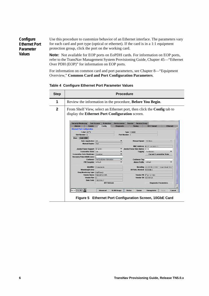
Configure Ethernet Port Parameter Values
Use this procedure to customize behavior of an Ethernet interface. The parameters vary for each card and port type (optical or ethernet). If the card is in a 1:1 equipment protection group, click the port on the working card.
Note: Not available for EOP ports on EoPDH cards. For information on EOP ports, refer to the TransNav Management System Provisioning Guide, Chapter 45—“Ethernet Over PDH (EOP)” for information on EOP ports.
For information on common card and port parameters, see Chapter 8—“Equipment Overview,” Common Card and Port Configuration Parameters.
Table 4 Configure Ethernet Port Parameter Values
Step Procedure
1 Review the information in the procedure, Before You Begin.
2 From Shelf View, select an Ethernet port, then click the Config tab to display the Ethernet Port Configuration screen.
Figure 5 Ethernet Port Configuration Screen, 10GbE Card
6 TransNav Provisioning Guide, Release TN5.0.x
3 The following parameters display on the Main tab for NGE, NGE Plus, 10GbE and GbE-10 cards depending on the card and port type selected. (EoPDH cards do not have a Main tab.) All parameters display on all cards and ports unless otherwise specified.
Auto-negotiation: Available on all TE-100 ports and Traverse cards except 10GbE. Select to allow two devices on an Ethernet segment (link partners) to determine mutually agreeable settings for speed, duplex, and pause flow control. Valid values are On (default) or Off (always Off for 10GbE cards).
Manual Duplex: Indicates the mode of operation for this port.
Manual Speed: Configure the data rate of the link.
Manual Crossover (ETH100TX ports on NGE, NGE Plus and EoPDH cards only): Controls the MDI/MDIX configuration of the port.
For more information on these parameters, see Configure Auto Negotiation.
4 Change any of the following parameters for any Ethernet interface:
Jumbo Frame Support (Traverse, GbE and 10GbE only): Indicates whether jumbo frames are supported. Select one of the following:• Enabled (default): Jumbo frame support is enabled.• Disabled: Jumbo frame support is disabled. Received jumbo frames will
be dropped and no jumbo frames will be transmitted.
Jumbo Frame Size (bytes) (Traverse only): Enter the jumbo frame size (available only when Jumbo Frame Support is Enabled). Range is 1522 to 9600 bytes; default is 9600 bytes.
Tagging: Specify the expected type of VLAN tagging on this Ethernet port, LAG, or EOS port.• Port-based (default)• Customer-tagged• Service-tagged• Untagged (TE-100, Ethernet port, EOS port parameters only)
For more information on VLAN tagging, see Chapter 50—“VLAN Tagging on Traverse Ethernet Services.”
5 Transmitter State (GBE and 10GbE ports only): Determines if the laser on a GBE or 10GbE port is turned on or off. • On (default): The laser is on.• Off: Select to turn off the laser.
Table 4 Configure Ethernet Port Parameter Values (continued)
Step Procedure
TransNav Provisioning Guide, Release TN5.0.x 7
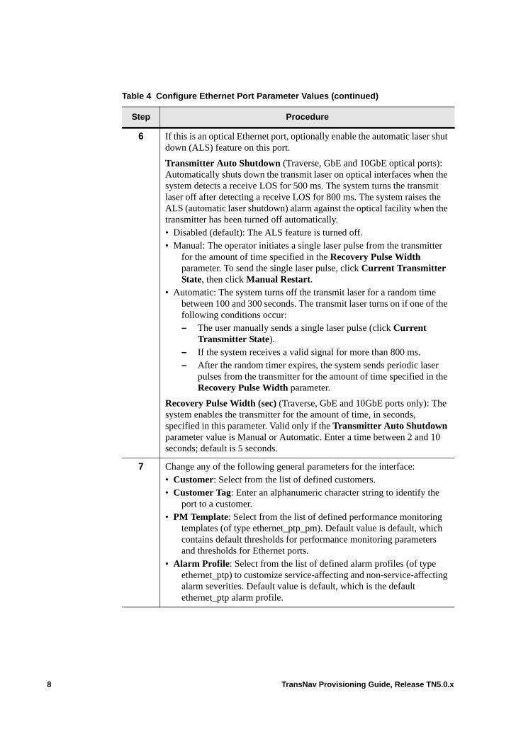
6 If this is an optical Ethernet port, optionally enable the automatic laser shut down (ALS) feature on this port.
Transmitter Auto Shutdown (Traverse, GbE and 10GbE optical ports): Automatically shuts down the transmit laser on optical interfaces when the system detects a receive LOS for 500 ms. The system turns the transmit laser off after detecting a receive LOS for 800 ms. The system raises the ALS (automatic laser shutdown) alarm against the optical facility when the transmitter has been turned off automatically.• Disabled (default): The ALS feature is turned off.• Manual: The operator initiates a single laser pulse from the transmitter
for the amount of time specified in the Recovery Pulse Width parameter. To send the single laser pulse, click Current Transmitter State, then click Manual Restart.
• Automatic: The system turns off the transmit laser for a random time between 100 and 300 seconds. The transmit laser turns on if one of the following conditions occur:– The user manually sends a single laser pulse (click Current
Transmitter State). – If the system receives a valid signal for more than 800 ms.– After the random timer expires, the system sends periodic laser
pulses from the transmitter for the amount of time specified in the Recovery Pulse Width parameter.
Recovery Pulse Width (sec) (Traverse, GbE and 10GbE ports only): The system enables the transmitter for the amount of time, in seconds, specified in this parameter. Valid only if the Transmitter Auto Shutdown parameter value is Manual or Automatic. Enter a time between 2 and 10 seconds; default is 5 seconds.
7 Change any of the following general parameters for the interface:• Customer: Select from the list of defined customers. • Customer Tag: Enter an alphanumeric character string to identify the
port to a customer.• PM Template: Select from the list of defined performance monitoring
templates (of type ethernet_ptp_pm). Default value is default, which contains default thresholds for performance monitoring parameters and thresholds for Ethernet ports.
• Alarm Profile: Select from the list of defined alarm profiles (of type ethernet_ptp) to customize service-affecting and non-service-affecting alarm severities. Default value is default, which is the default ethernet_ptp alarm profile.
Table 4 Configure Ethernet Port Parameter Values (continued)
Step Procedure
8 TransNav Provisioning Guide, Release TN5.0.x
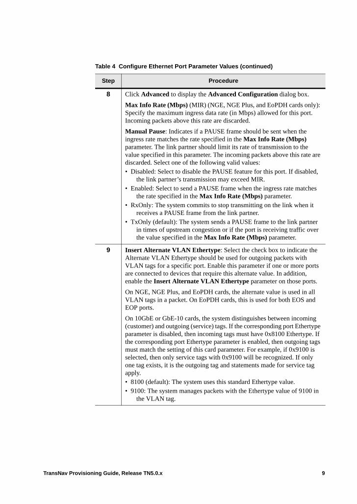
8 Click Advanced to display the Advanced Configuration dialog box.
Max Info Rate (Mbps) (MIR) (NGE, NGE Plus, and EoPDH cards only): Specify the maximum ingress data rate (in Mbps) allowed for this port. Incoming packets above this rate are discarded.
Manual Pause: Indicates if a PAUSE frame should be sent when the ingress rate matches the rate specified in the Max Info Rate (Mbps) parameter. The link partner should limit its rate of transmission to the value specified in this parameter. The incoming packets above this rate are discarded. Select one of the following valid values:• Disabled: Select to disable the PAUSE feature for this port. If disabled,
the link partner’s transmission may exceed MIR. • Enabled: Select to send a PAUSE frame when the ingress rate matches
the rate specified in the Max Info Rate (Mbps) parameter.• RxOnly: The system commits to stop transmitting on the link when it
receives a PAUSE frame from the link partner. • TxOnly (default): The system sends a PAUSE frame to the link partner
in times of upstream congestion or if the port is receiving traffic over the value specified in the Max Info Rate (Mbps) parameter.
9 Insert Alternate VLAN Ethertype: Select the check box to indicate the Alternate VLAN Ethertype should be used for outgoing packets with VLAN tags for a specific port. Enable this parameter if one or more ports are connected to devices that require this alternate value. In addition, enable the Insert Alternate VLAN Ethertype parameter on those ports.
On NGE, NGE Plus, and EoPDH cards, the alternate value is used in all VLAN tags in a packet. On EoPDH cards, this is used for both EOS and EOP ports.
On 10GbE or GbE-10 cards, the system distinguishes between incoming (customer) and outgoing (service) tags. If the corresponding port Ethertype parameter is disabled, then incoming tags must have 0x8100 Ethertype. If the corresponding port Ethertype parameter is enabled, then outgoing tags must match the setting of this card parameter. For example, if 0x9100 is selected, then only service tags with 0x9100 will be recognized. If only one tag exists, it is the outgoing tag and statements made for service tag apply.• 8100 (default): The system uses this standard Ethertype value. • 9100: The system manages packets with the Ethertype value of 9100 in
the VLAN tag.
Table 4 Configure Ethernet Port Parameter Values (continued)
Step Procedure
TransNav Provisioning Guide, Release TN5.0.x 9
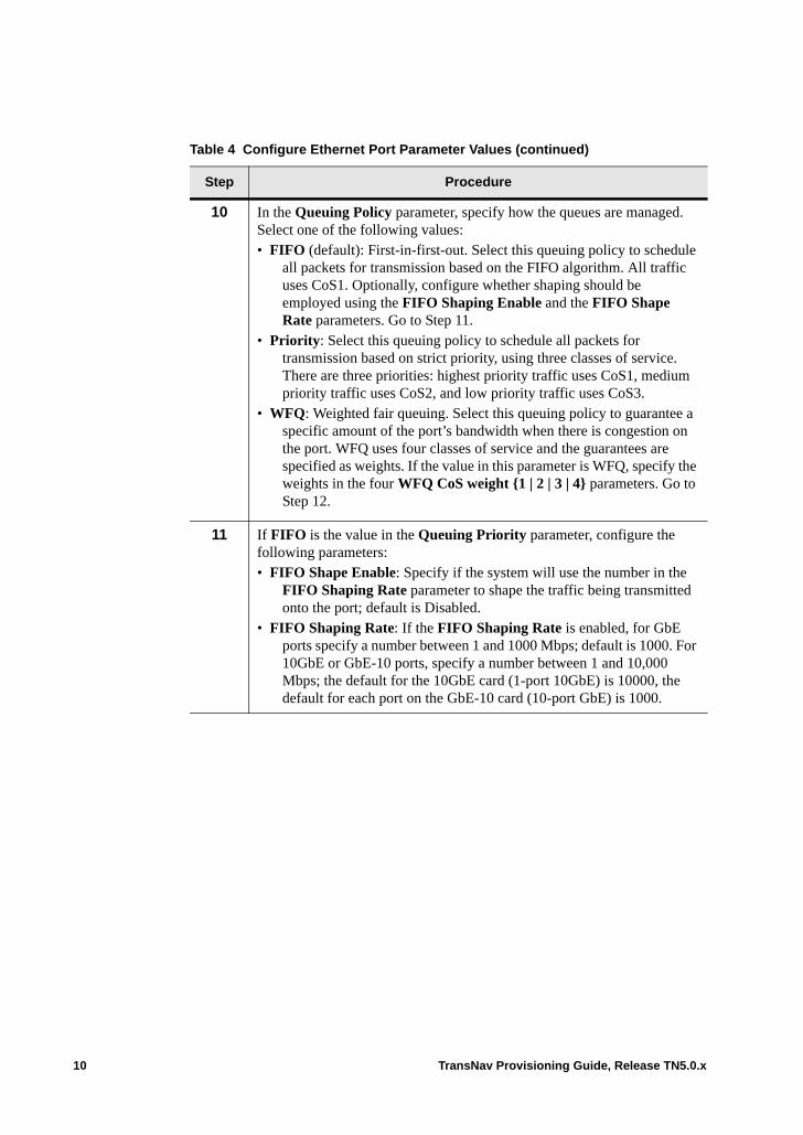
10 In the Queuing Policy parameter, specify how the queues are managed. Select one of the following values: • FIFO (default): First-in-first-out. Select this queuing policy to schedule
all packets for transmission based on the FIFO algorithm. All traffic uses CoS1. Optionally, configure whether shaping should be employed using the FIFO Shaping Enable and the FIFO Shape Rate parameters. Go to Step 11.
• Priority: Select this queuing policy to schedule all packets for transmission based on strict priority, using three classes of service. There are three priorities: highest priority traffic uses CoS1, medium priority traffic uses CoS2, and low priority traffic uses CoS3.
• WFQ: Weighted fair queuing. Select this queuing policy to guarantee a specific amount of the port’s bandwidth when there is congestion on the port. WFQ uses four classes of service and the guarantees are specified as weights. If the value in this parameter is WFQ, specify the weights in the four WFQ CoS weight {1 | 2 | 3 | 4} parameters. Go to Step 12.
11 If FIFO is the value in the Queuing Priority parameter, configure the following parameters:• FIFO Shape Enable: Specify if the system will use the number in the
FIFO Shaping Rate parameter to shape the traffic being transmitted onto the port; default is Disabled.
• FIFO Shaping Rate: If the FIFO Shaping Rate is enabled, for GbE ports specify a number between 1 and 1000 Mbps; default is 1000. For 10GbE or GbE-10 ports, specify a number between 1 and 10,000 Mbps; the default for the 10GbE card (1-port 10GbE) is 10000, the default for each port on the GbE-10 card (10-port GbE) is 1000.
Table 4 Configure Ethernet Port Parameter Values (continued)
Step Procedure
10 TransNav Provisioning Guide, Release TN5.0.x
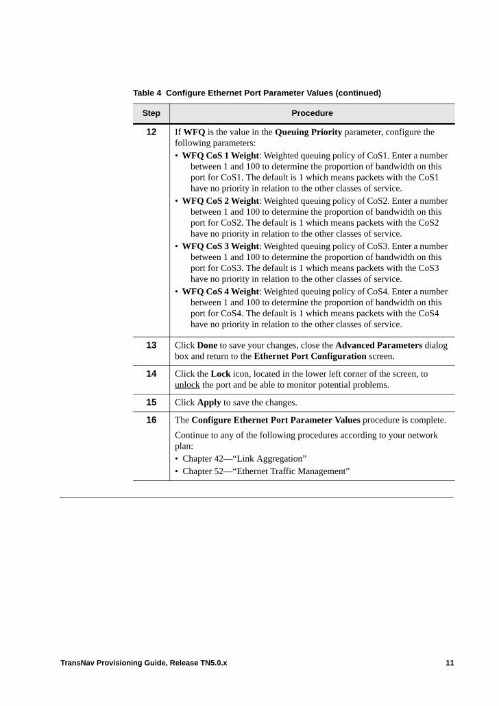
12 If WFQ is the value in the Queuing Priority parameter, configure the following parameters:• WFQ CoS 1 Weight: Weighted queuing policy of CoS1. Enter a number
between 1 and 100 to determine the proportion of bandwidth on this port for CoS1. The default is 1 which means packets with the CoS1 have no priority in relation to the other classes of service.
• WFQ CoS 2 Weight: Weighted queuing policy of CoS2. Enter a number between 1 and 100 to determine the proportion of bandwidth on this port for CoS2. The default is 1 which means packets with the CoS2 have no priority in relation to the other classes of service.
• WFQ CoS 3 Weight: Weighted queuing policy of CoS3. Enter a number between 1 and 100 to determine the proportion of bandwidth on this port for CoS3. The default is 1 which means packets with the CoS3 have no priority in relation to the other classes of service.
• WFQ CoS 4 Weight: Weighted queuing policy of CoS4. Enter a number between 1 and 100 to determine the proportion of bandwidth on this port for CoS4. The default is 1 which means packets with the CoS4 have no priority in relation to the other classes of service.
13 Click Done to save your changes, close the Advanced Parameters dialog box and return to the Ethernet Port Configuration screen.
14 Click the Lock icon, located in the lower left corner of the screen, to unlock the port and be able to monitor potential problems.
15 Click Apply to save the changes.
16 The Configure Ethernet Port Parameter Values procedure is complete.
Continue to any of the following procedures according to your network plan:• Chapter 42—“Link Aggregation”• Chapter 52—“Ethernet Traffic Management”
Table 4 Configure Ethernet Port Parameter Values (continued)
Step Procedure
TransNav Provisioning Guide, Release TN5.0.x 11
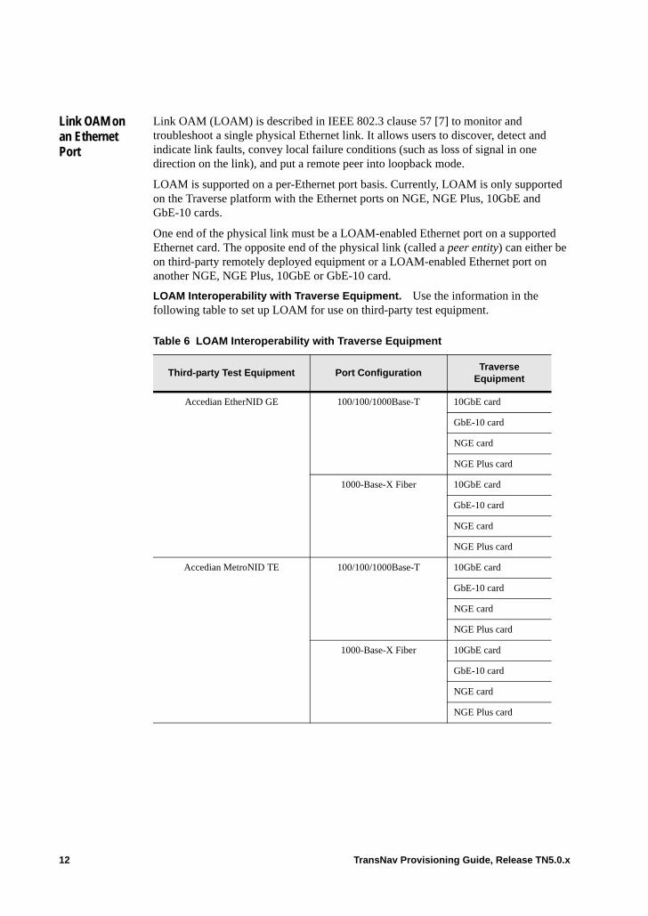
Link OAM on an Ethernet Port
Link OAM (LOAM) is described in IEEE 802.3 clause 57 [7] to monitor and troubleshoot a single physical Ethernet link. It allows users to discover, detect and indicate link faults, convey local failure conditions (such as loss of signal in one direction on the link), and put a remote peer into loopback mode.
LOAM is supported on a per-Ethernet port basis. Currently, LOAM is only supported on the Traverse platform with the Ethernet ports on NGE, NGE Plus, 10GbE and GbE-10 cards.
One end of the physical link must be a LOAM-enabled Ethernet port on a supported Ethernet card. The opposite end of the physical link (called a peer entity) can either be on third-party remotely deployed equipment or a LOAM-enabled Ethernet port on another NGE, NGE Plus, 10GbE or GbE-10 card.
LOAM Interoperability with Traverse Equipment. Use the information in the following table to set up LOAM for use on third-party test equipment.
Table 6 LOAM Interoperability with Traverse Equipment
Third-party Test Equipment Port ConfigurationTraverse
Equipment
Accedian EtherNID GE 100/100/1000Base-T 10GbE card
GbE-10 card
NGE card
NGE Plus card
1000-Base-X Fiber 10GbE card
GbE-10 card
NGE card
NGE Plus card
Accedian MetroNID TE 100/100/1000Base-T 10GbE card
GbE-10 card
NGE card
NGE Plus card
1000-Base-X Fiber 10GbE card
GbE-10 card
NGE card
NGE Plus card
12 TransNav Provisioning Guide, Release TN5.0.x

Prior to connecting the third-party test equipment to the Ethernet port, you will need an IP address for the third-party test equipment and the appropriate type and length of fiber cable for your set up.
Telco Systems 340 100/100/1000Base-T 10GbE card
GbE-10 card
NGE card
NGE Plus card
1000-Base-X Fiber 10GbE card
GbE-10 card
NGE card
NGE Plus card
Table 6 LOAM Interoperability with Traverse Equipment
Third-party Test Equipment Port ConfigurationTraverse
Equipment
TransNav Provisioning Guide, Release TN5.0.x 13
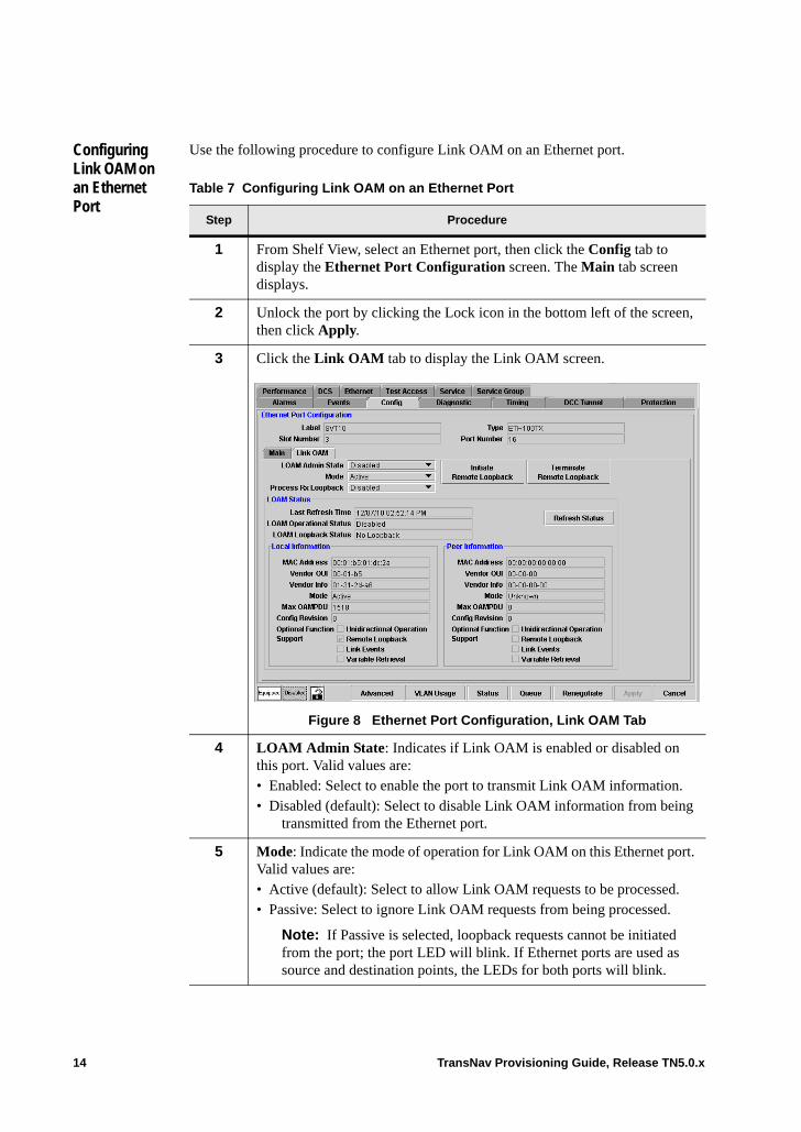
Configuring Link OAM on an Ethernet Port
Use the following procedure to configure Link OAM on an Ethernet port.
Table 7 Configuring Link OAM on an Ethernet Port
Step Procedure
1 From Shelf View, select an Ethernet port, then click the Config tab to display the Ethernet Port Configuration screen. The Main tab screen displays.
2 Unlock the port by clicking the Lock icon in the bottom left of the screen, then click Apply.
3 Click the Link OAM tab to display the Link OAM screen.
Figure 8 Ethernet Port Configuration, Link OAM Tab
4 LOAM Admin State: Indicates if Link OAM is enabled or disabled on this port. Valid values are:• Enabled: Select to enable the port to transmit Link OAM information.• Disabled (default): Select to disable Link OAM information from being
transmitted from the Ethernet port.
5 Mode: Indicate the mode of operation for Link OAM on this Ethernet port. Valid values are: • Active (default): Select to allow Link OAM requests to be processed. • Passive: Select to ignore Link OAM requests from being processed.
Note: If Passive is selected, loopback requests cannot be initiated from the port; the port LED will blink. If Ethernet ports are used as source and destination points, the LEDs for both ports will blink.
14 TransNav Provisioning Guide, Release TN5.0.x
After LOAM is set up on both ends of the physical link, click Initiate Remote Loopback to initiate loopback tests on the remote OAM entity. To terminate the remote loopback tests, click Terminate Remote Loopback.
View the status of the LOAM setup in the LOAM Status pane.
Last Refresh Time: Indicates the last time the LOAM status information was updated.
LOAM Operational Status: Indicates the operational status of LOAM on the local Ethernet port. Valid values are: • Disabled: Indicates the OAM Administrative State is disabled.• Link Fault: The link has detected a fault. • Passive Wait: The OAM mode on the local Ethernet port is passive; no information
has been received from the remote OAM Ethernet port. • Active Send Local: The OAM mode on the local Ethernet port is active; no
information has been received from the remote OAM Ethernet port.• Send Local and Remote: The local OAM Ethernet port has received information from
the remote OAM Ethernet port and is evaluating it. • Send Local and Remote OK: The local OAM Ethernet port has received and accepted
information from the remote OAM Ethernet port. The remote OAM Ethernet port is evaluating return OAM information from the local OAM Ethernet port.
• OAM Peering Locally Rejected: The local OAM Ethernet port has received and rejected information from the remote OAM Ethernet port.
• OAM Peering Remotely Rejected: The remote OAM Ethernet port has rejected the OAM discovery.
• Operational: OAM discovery is complete.• Non-operational, Half-duplex: The link is half-duplex. Link OAM is not supported
on half-duplex.
6 Process Rx Loopback: Indicates if remote OAM loopback requests will be processed from this port. Valid values are:• Enabled: Select to enable remote OAM loopback requests to be
processed. • Disabled (default): Select to ignore remote OAM loopback requests.
7* Click Apply to enable the changes.
8 The Configuring Link OAM on an Ethernet Port procedure is complete.
If the peer entity being used to test the link integrity is an Ethernet port on a separate Ethernet card, repeat Steps 1 through 7 on the peer Ethernet port.
If the peer entity being used to test the link integrity is third-party test equipment, please refer to the user documentation for that specific test equipment for set up and usage instructions.
Table 7 Configuring Link OAM on an Ethernet Port (continued)
Step Procedure
TransNav Provisioning Guide, Release TN5.0.x 15

LOAM Loopback Status: Indicates the loopback status of the local Ethernet port. Valid values are:• No Loopback: No loopback is in progress. • Initiating Loopback: Loopback is being in ita ted from the local OAM Ethernet port
to a remote OAM entity (test set or Ethernet port).• Remote Loopback: A loopback request has been sent from the local Ethernet port to
the remote OAM entity but a response has not been received.• Terminating Loopback: A request to terminate loopback has been sent from the local
Ethernet port.• Local Loopback: A loopback request has been received from the remote OAM entity.• Unknown: The current loopback state is unknown while the request is in transition.
To view updated information, click Refresh Status. Updated information also displays if you leave the Link OAM tab and then re-open it.
LOAM Status Information for Local and Peer Entity Ports. The LOAM Status panel includes the following information that is transmitted on the Local and Peer OAM-enabled ports. The information in these parameters is included in the LOAM PDUs that are transmitted.
MAC Address: The MAC address of the Local or Peer Ethernet port.
Vendor OUI: Indicates the vendor OUI (organizationally unique identifier) associated with the MAC address.
Vendor Info: Indicates vendor specific information.
Mode: Indicates the provisioned Link OAM mode of the port. For more information, see Step 5 in the Configuring Link OAM on an Ethernet Port procedure.
Max OAMPDU: Maximum amount of OAM Protocol Data Units that can be transmitted.
Config Revision: Indicates the revision of the most recently transmitted OAMPDU data encoded in TLV (Type-Length-Value) format.
Optional Function Support: Identifies the Link OAM functions that are supported by the OAM entity (test set or Ethernet port) on a Traverse system. Supported functions that are active are indicated by a check mark in the box preceding the function. • Unidirectional Operation (Planned for future release.) • Remote Loopback • Link Events (Planned for future release.) Events for link events on Traverse
equipment will not be reported, however, link events for third-party equipment will be reported.
• Variable Retrieval (Planned for future release.)
16 TransNav Provisioning Guide, Release TN5.0.x
Auto Negotiation
Auto-negotiation is a process described in IEEE standard 802.3 that allows two devices on an Ethernet segment (link partners) to determine mutually agreeable settings for speed, duplex, and pause flow control.
When auto-negotiation is enabled for a port, the system initiates auto-negotiation whenever:• the port receives a signal when there had previously been no signal.• a link partner initiates auto-negotiation.• the operator makes any change to the advertisement parameters for the port.• the operator changes the value in the Auto-negotiation parameter to ON.• the operator requests that auto-negotiation be restarted immediately on a specified
port.
The auto-negotiation process completes in approximately three seconds.
The link is considered down and a Link Fail alarm appears when one of the following instances occur:• The link partners are unable to resolve to a common mode of operation for any
negotiated parameter.• One or more link partners does not advertise any parameters.• If the detected speed and assumed duplex of the link partner are not compatible with
the Traverse.
If auto-negotiation is enabled for an FE port but the link partner does not negotiate, the system assumes that the link partner is operating in half duplex mode.
Manual Pause, Advertise 1000M Full Duplex, and Advertised PAUSE RX are provisionable. Through the Manual Pause parameter, Forced Pause Receive is provisionable and Forced Pause Transmit is disabled. Advertised PAUSE TX is disabled.
To enable auto-negotiation between the Traverse system and a TransAccess 200 Mux, ensure the Traverse BP DCN connection is either static 100/half duplex or
Important: By default, the Auto-negotiation feature is enabled. The exception is on 10GBE and EOP ports (available only on Traverse nodes), where auto-negotiation and pause functionality are unavailable. For GBE-10 TX ports, auto-negotiation is “forced” with speed set to 10 Gbps and duplex set to FULL_DUPLEX.
However, the Traverse allows the operator to disable auto-negotiation for both ETH100TX and optical GbE ports on Traverse and TE-100 nodes. On Traverse only, auto-negotiation is always performed on copper GbE TX ports.
Force10 recommends that if the peer device is 802.3 compliant, the operator leave the auto-negotiation feature enabled. Auto-negotiation is required for electrical GbE ports (IEEE 802.3 clause 40.5).
To avoid unpredictable system behavior, Force10 recommends never disabling the auto-negotiation feature for a port on a 10-port GbE card that has an electrical SFP installed instead of an optical SFP.
TransNav Provisioning Guide, Release TN5.0.x 17

auto-negotiation Advertise 100M Half Duplex. However, if the BP DCN connection is set at auto-negotiation Advertise 100M Half Duplex, the far-end must advertise 100/half duplex.
18 TransNav Provisioning Guide, Release TN5.0.x

Configure Auto Negotiation
Use the following procedure to help you configure auto-negotiation on a Ethernet port.
Table 9 Configure Auto-negotiation
Step Procedure
1 In Shelf View, click an Ethernet port, then click the Config tab to display the Ethernet Port Configuration screen.
If this card is in a 1:1 equipment protection group on a Traverse node, click the port on the working card.
Figure 10 Ethernet Port Configuration, 10GbE Card
2 In the Auto-negotiation parameter, select one of the following values: • On (default for all port types): Negotiate the speed, duplex attributes,
and pause flow control of the link based on the values in the Advertise parameters (as applicable to the port type). – For ETH100TX ports, go to Step 3.– For GBE ports, go to Step 4.– For GBETX ports on a Traverse node, go to Step 5.
• Off: Available for ETH100TX and optical GBE ports only. The link starts up and initializes with the values in the Manual Speed, Manual Duplex, and Manual PAUSE fields (as applicable to the port type). – For ETH100TX ports, go to Step 6.– For GBE ports, go to Step 7.
TransNav Provisioning Guide, Release TN5.0.x 19
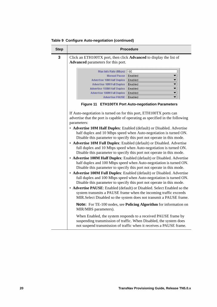
3 Click an ETH100TX port, then click Advanced to display the list of Advanced parameters for this port.
Figure 11 ETH100TX Port Auto-negotiation Parameters
If Auto-negotiation is turned on for this port, ETH100TX ports can advertise that the port is capable of operating as specified in the following parameters:• Advertise 10M Half Duplex: Enabled (default) or Disabled. Advertise
half duplex and 10 Mbps speed when Auto-negotiation is turned ON. Disable this parameter to specify this port not operate in this mode.
• Advertise 10M Full Duplex: Enabled (default) or Disabled. Advertise full duplex and 10 Mbps speed when Auto-negotiation is turned ON. Disable this parameter to specify this port not operate in this mode.
• Advertise 100M Half Duplex: Enabled (default) or Disabled. Advertise half duplex and 100 Mbps speed when Auto-negotiation is turned ON. Disable this parameter to specify this port not operate in this mode.
• Advertise 100M Full Duplex: Enabled (default) or Disabled. Advertise full duplex and 100 Mbps speed when Auto-negotiation is turned ON. Disable this parameter to specify this port not operate in this mode.
• Advertise PAUSE: Enabled (default) or Disabled. Select Enabled so the system transmits a PAUSE frame when the incoming traffic exceeds MIR.Select Disabled so the system does not transmit a PAUSE frame.
Note: For TE-100 nodes, see Policing Algorithm for information on MIR/MBS parameters).
When Enabled, the system responds to a received PAUSE frame by suspending transmission of traffic. When Disabled, the system does not suspend transmission of traffic when it receives a PAUSE frame.
Table 9 Configure Auto-negotiation (continued)
Step Procedure
20 TransNav Provisioning Guide, Release TN5.0.x
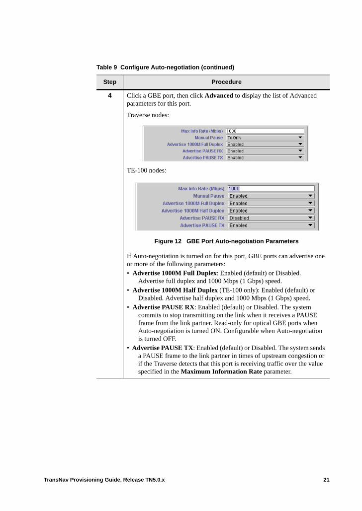
4 Click a GBE port, then click Advanced to display the list of Advanced parameters for this port.
Traverse nodes:
TE-100 nodes:
Figure 12 GBE Port Auto-negotiation Parameters
If Auto-negotiation is turned on for this port, GBE ports can advertise one or more of the following parameters:• Advertise 1000M Full Duplex: Enabled (default) or Disabled.
Advertise full duplex and 1000 Mbps (1 Gbps) speed. • Advertise 1000M Half Duplex (TE-100 only): Enabled (default) or
Disabled. Advertise half duplex and 1000 Mbps (1 Gbps) speed. • Advertise PAUSE RX: Enabled (default) or Disabled. The system
commits to stop transmitting on the link when it receives a PAUSE frame from the link partner. Read-only for optical GBE ports when Auto-negotiation is turned ON. Configurable when Auto-negotiation is turned OFF.
• Advertise PAUSE TX: Enabled (default) or Disabled. The system sends a PAUSE frame to the link partner in times of upstream congestion or if the Traverse detects that this port is receiving traffic over the value specified in the Maximum Information Rate parameter.
Table 9 Configure Auto-negotiation (continued)
Step Procedure
TransNav Provisioning Guide, Release TN5.0.x 21

5 On a Traverse node only, click a GBETX port then click Advanced to display the list of advanced parameters for this port.
Figure 13 GBETX Port Auto-negotiation Parameters
If Auto-negotiation is turned on for this port, GBETX ports can advertise one or more of the following parameters:• Advertise 1000M Half Duplex: Enabled (default) or Disabled.
Advertise half duplex and 1000 Mbps (1 Gbps) speed. • Advertise 1000M Full Duplex: Enabled (default) or Disabled.
Advertise full duplex and 1000 Mbps (1 Gbps) speed. • Advertise GBE RX PAUSE: Enabled or Disabled (default). The
Traverse commits to stop transmitting on the link when it receives a PAUSE frame from the link partner.
• Advertise GBE TX PAUSE: Enabled (default) or Disabled. The Traverse will send a PAUSE frame to the link partner in times of upstream congestion or if the Traverse detects that this port is receiving traffic over the value specified in the Maximum Information Rate parameter.
Table 9 Configure Auto-negotiation (continued)
Step Procedure
22 TransNav Provisioning Guide, Release TN5.0.x
6 If Auto-negotiation is turned OFF for this ETH100TX port (NGE and EoPDH cards only), set the following parameters:• Manual Duplex: Indicates the mode of operation for this port based on
IEEE standard 802.3.– Full (default): The port operates in full duplex mode and allows
simultaneous transmissions on the link.– Half: The port operates in half-duplex mode and uses CSMA/CD
to share access to the link.• Manual Speed: Configure the data rate of the link:
– 10 Mbps– 100 Mbps (default)
• Manual Pause: Configure if the system will send a PAUSE frame to the link partner in times of upstream congestion or if the traffic on this port is bursting over the value specified in the Maximum Information Rate parameter.
• Manual Crossover: Controls the MDI/MDIX configuration of this port. – Enabled. Select to reverse the transmit and receive on this port.
Turns a straight-through cable into a crossover cable.– Disabled (default)
Table 9 Configure Auto-negotiation (continued)
Step Procedure
TransNav Provisioning Guide, Release TN5.0.x 23

V
7 When Auto-negotiation is turned OFF for this optical GBE port, set the following parameters:• Manual Duplex: Indicates the mode of operation for this port based on
IEEE standard 802.3.– Full (default): The port operates in full duplex mode and allows
simultaneous transmissions on the link.– Half: The port operates in half-duplex mode and uses CSMA/CD
to share access to the link.• Manual Speed (Read only): 1000 Mbps (1 Gbps)• Manual Pause: Configure if the system will send a PAUSE frame to the
link partner in times of upstream congestion or if the traffic on this port is bursting over the value specified in the Maximum Information Rate parameter– Enabled. The system will send a PAUSE frame and commit to
stopping traffic if it receives a PAUSE frame.– Disabled. The system does not send or receive PAUSE frames.– TX Only (default). The system will send a PAUSE frame to the
link partner in times of upstream congestion or if the Traverse detects that this port is receiving traffic over the value specified in the Maximum Information Rate parameter.
– RX only. The Traverse commits to stop transmitting on the link when it receives a PAUSE frame from the link partner.
8 The Configure Auto Negotiation procedure is complete.
Table 9 Configure Auto-negotiation (continued)
Step Procedure
24 TransNav Provisioning Guide, Release TN5.0.x

View the SFP / XFP Port Parameters
On a Force10 Traverse node in Shelf View, click a SFP (small form pluggable transceiver), XFP (10Gbps small form pluggable transceiver), or an optical port, then click the Config tab to display the Ethernet Port Configuration screen. For NGE, NGE Plus, 10GbE and GbE-10 cards, the Main tab displays.
If a pluggable transceiver is in use on a card, the SFP or XFP information displays at the bottom of the screen. Use this procedure to view the SFP or XFP information.
Important: Use SFPs or XFPs approved by Force10 to avoid possible equipment damage that may occur, thus voiding the warranty.
Table 14 View the SFP or XFP Information
Step Procedure
1 In Shelf View, click an Ethernet port, then click the Config tab.
If this card is in a 1:1 equipment protection group on a Traverse node, click the port on the working card.
Figure 15 Ethernet Port Configuration Screen, 10GbE Main Tab
TransNav Provisioning Guide, Release TN5.0.x 25

2 The Ethernet Port Configuration screen displays. The SFP or XFP information is available at the bottom of the screen. For NGE, NGE Plus, 10GbE and GbE-10 cards, this is on the Main tab as shown in Figure 15.
Identifier: Indicates the type of port where the transceiver is located. The port can be a SFP (small form-factor pluggable transceiver), XFP (10Gbps small form-form factor pluggable transceiver) or an optical port. If a transceiver is not in use, the parameter displays Unavailable.
Wavelength (nm): Displays the laser wavelength of the transceiver in nanometers.
Diag Monitoring Type: The type of diagnostic monitoring (if any) that is implemented in the transceiver.
Vendor Name: Indicates the name of the hardware vendor for this transceiver.
Vendor Rev: Displays the vendor’s hardware revision number.
Date Code: Displays the date that the hardware was manufactured.
Encoding: Indicates the serial encoding mechanism that is the nominal design target of the transceiver in use.
Bit Rate, Nominal: Displays the nominal bit rate in increments of 100 Mbps.
Vendor PN: Indicates the vendor’s hardware part number.
Vendor SN: Indicates the vendor’s serial number of the hardware.
3 Click Refresh to retrieve the current data.
Click Close to close the dialog box and return to the main screen.
4 The View the SFP / XFP Port Parameters procedure is complete.
Table 14 View the SFP or XFP Information (continued)
Step Procedure
26 TransNav Provisioning Guide, Release TN5.0.x
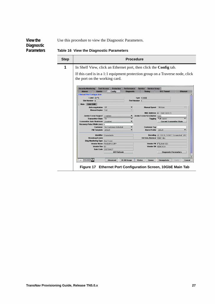
View the Diagnostic Parameters
Use this procedure to view the Diagnostic Parameters.
Table 16 View the Diagnostic Parameters
Step Procedure
1 In Shelf View, click an Ethernet port, then click the Config tab.
If this card is in a 1:1 equipment protection group on a Traverse node, click the port on the working card.
Figure 17 Ethernet Port Configuration Screen, 10GbE Main Tab
TransNav Provisioning Guide, Release TN5.0.x 27
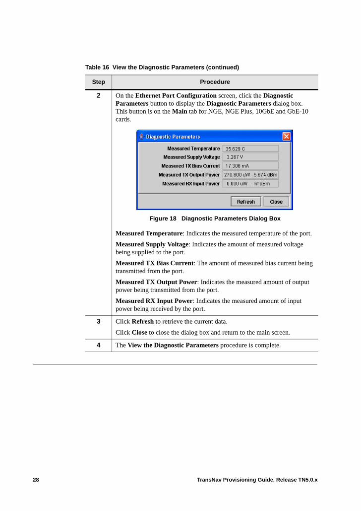
2 On the Ethernet Port Configuration screen, click the Diagnostic Parameters button to display the Diagnostic Parameters dialog box. This button is on the Main tab for NGE, NGE Plus, 10GbE and GbE-10 cards.
Figure 18 Diagnostic Parameters Dialog Box
Measured Temperature: Indicates the measured temperature of the port.
Measured Supply Voltage: Indicates the amount of measured voltage being supplied to the port.
Measured TX Bias Current: The amount of measured bias current being transmitted from the port.
Measured TX Output Power: Indicates the measured amount of output power being transmitted from the port.
Measured RX Input Power: Indicates the measured amount of input power being received by the port.
3 Click Refresh to retrieve the current data.
Click Close to close the dialog box and return to the main screen.
4 The View the Diagnostic Parameters procedure is complete.
Table 16 View the Diagnostic Parameters (continued)
Step Procedure
28 TransNav Provisioning Guide, Release TN5.0.x
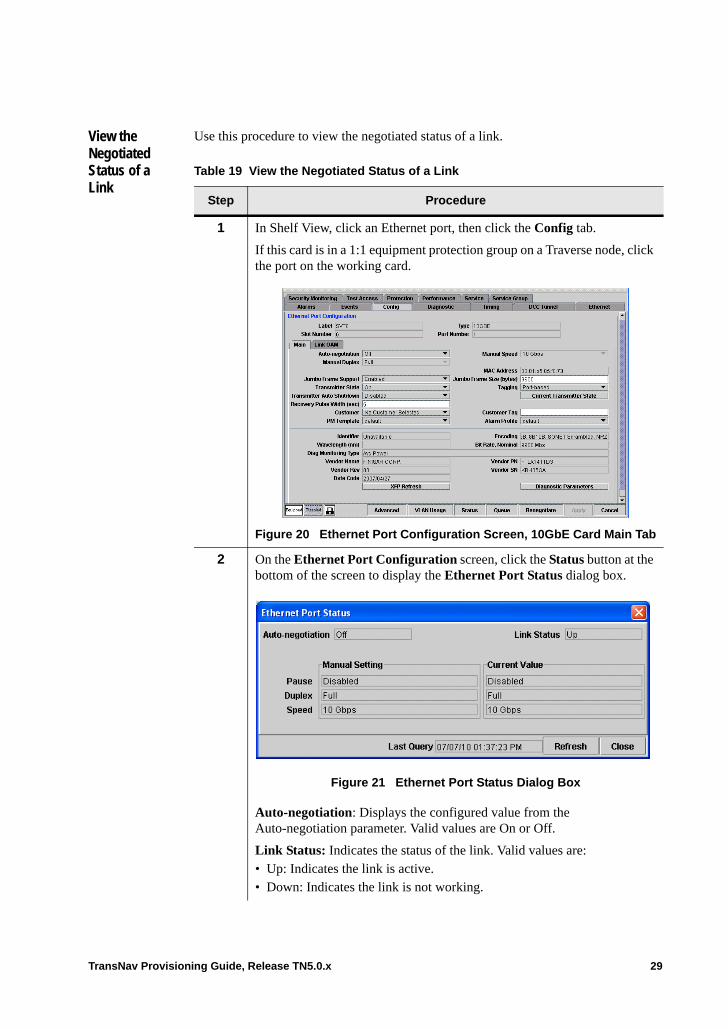
View the Negotiated Status of a Link
Use this procedure to view the negotiated status of a link.
Table 19 View the Negotiated Status of a Link
Step Procedure
1 In Shelf View, click an Ethernet port, then click the Config tab.
If this card is in a 1:1 equipment protection group on a Traverse node, click the port on the working card.
Figure 20 Ethernet Port Configuration Screen, 10GbE Card Main Tab
2 On the Ethernet Port Configuration screen, click the Status button at the bottom of the screen to display the Ethernet Port Status dialog box.
Figure 21 Ethernet Port Status Dialog Box
Auto-negotiation: Displays the configured value from the Auto-negotiation parameter. Valid values are On or Off.
Link Status: Indicates the status of the link. Valid values are:• Up: Indicates the link is active.• Down: Indicates the link is not working.
TransNav Provisioning Guide, Release TN5.0.x 29
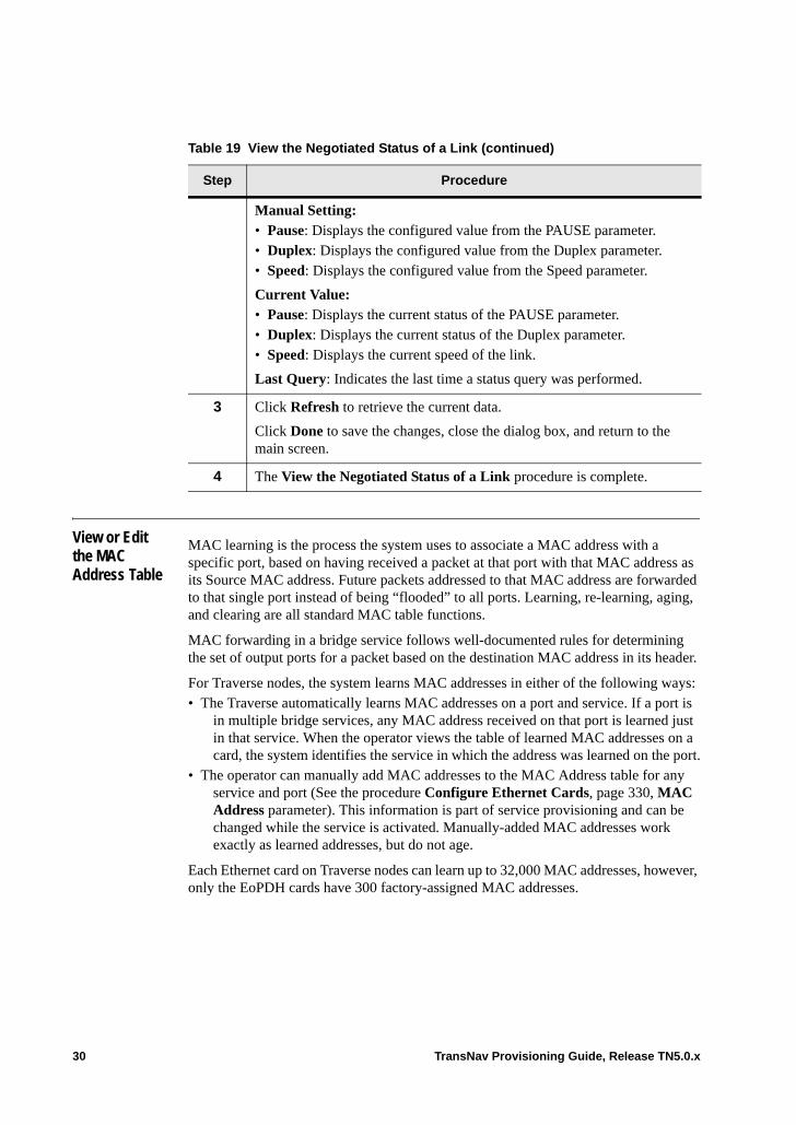
View or Edit the MAC Address Table
MAC learning is the process the system uses to associate a MAC address with a specific port, based on having received a packet at that port with that MAC address as its Source MAC address. Future packets addressed to that MAC address are forwarded to that single port instead of being “flooded” to all ports. Learning, re-learning, aging, and clearing are all standard MAC table functions.
MAC forwarding in a bridge service follows well-documented rules for determining the set of output ports for a packet based on the destination MAC address in its header.
For Traverse nodes, the system learns MAC addresses in either of the following ways:• The Traverse automatically learns MAC addresses on a port and service. If a port is
in multiple bridge services, any MAC address received on that port is learned just in that service. When the operator views the table of learned MAC addresses on a card, the system identifies the service in which the address was learned on the port.
• The operator can manually add MAC addresses to the MAC Address table for any service and port (See the procedure Configure Ethernet Cards, page 330, MAC Address parameter). This information is part of service provisioning and can be changed while the service is activated. Manually-added MAC addresses work exactly as learned addresses, but do not age.
Each Ethernet card on Traverse nodes can learn up to 32,000 MAC addresses, however, only the EoPDH cards have 300 factory-assigned MAC addresses.
Manual Setting: • Pause: Displays the configured value from the PAUSE parameter.• Duplex: Displays the configured value from the Duplex parameter.• Speed: Displays the configured value from the Speed parameter.
Current Value:• Pause: Displays the current status of the PAUSE parameter.• Duplex: Displays the current status of the Duplex parameter.• Speed: Displays the current speed of the link.
Last Query: Indicates the last time a status query was performed.
3 Click Refresh to retrieve the current data.
Click Done to save the changes, close the dialog box, and return to the main screen.
4 The View the Negotiated Status of a Link procedure is complete.
Table 19 View the Negotiated Status of a Link (continued)
Step Procedure
30 TransNav Provisioning Guide, Release TN5.0.x
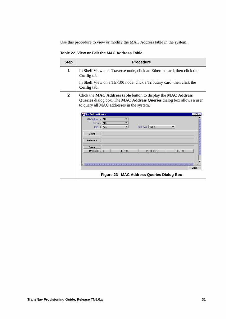
Use this procedure to view or modify the MAC Address table in the system.
Table 22 View or Edit the MAC Address Table
Step Procedure
1 In Shelf View on a Traverse node, click an Ethernet card, then click the Config tab.
In Shelf View on a TE-100 node, click a Tributary card, then click the Config tab.
2 Click the MAC Address table button to display the MAC Address Queries dialog box. The MAC Address Queries dialog box allows a user to query all MAC addresses in the system.
Figure 23 MAC Address Queries Dialog Box
TransNav Provisioning Guide, Release TN5.0.x 31
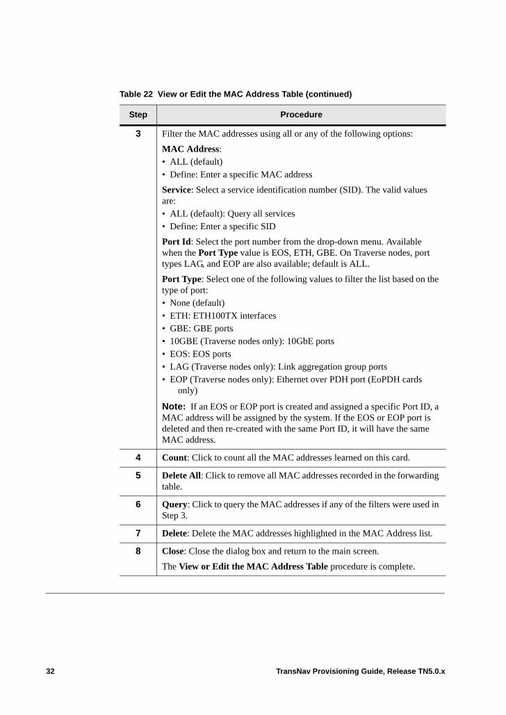
3 Filter the MAC addresses using all or any of the following options:
MAC Address:• ALL (default) • Define: Enter a specific MAC address
Service: Select a service identification number (SID). The valid values are: • ALL (default): Query all services• Define: Enter a specific SID
Port Id: Select the port number from the drop-down menu. Available when the Port Type value is EOS, ETH, GBE. On Traverse nodes, port types LAG, and EOP are also available; default is ALL.
Port Type: Select one of the following values to filter the list based on the type of port:• None (default)• ETH: ETH100TX interfaces• GBE: GBE ports• 10GBE (Traverse nodes only): 10GbE ports• EOS: EOS ports • LAG (Traverse nodes only): Link aggregation group ports• EOP (Traverse nodes only): Ethernet over PDH port (EoPDH cards
only)
Note: If an EOS or EOP port is created and assigned a specific Port ID, a MAC address will be assigned by the system. If the EOS or EOP port is deleted and then re-created with the same Port ID, it will have the same MAC address.
4 Count: Click to count all the MAC addresses learned on this card.
5 Delete All: Click to remove all MAC addresses recorded in the forwarding table.
6 Query: Click to query the MAC addresses if any of the filters were used in Step 3.
7 Delete: Delete the MAC addresses highlighted in the MAC Address list.
8 Close: Close the dialog box and return to the main screen.
The View or Edit the MAC Address Table procedure is complete.
Table 22 View or Edit the MAC Address Table (continued)
Step Procedure
32 TransNav Provisioning Guide, Release TN5.0.x
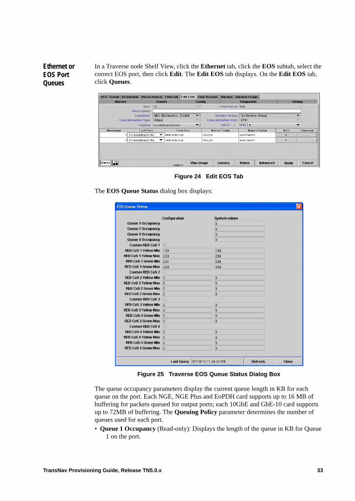
Ethernet or EOS Port Queues
In a Traverse node Shelf View, click the Ethernet tab, click the EOS subtab, select the correct EOS port, then click Edit. The Edit EOS tab displays. On the Edit EOS tab, click Queues.
Figure 24 Edit EOS Tab
The EOS Queue Status dialog box displays:
Figure 25 Traverse EOS Queue Status Dialog Box
The queue occupancy parameters display the current queue length in KB for each queue on the port. Each NGE, NGE Plus and EoPDH card supports up to 16 MB of buffering for packets queued for output ports; each 10GbE and GbE-10 card supports up to 72MB of buffering. The Queuing Policy parameter determines the number of queues used for each port. • Queue 1 Occupancy (Read-only): Displays the length of the queue in KB for Queue
1 on the port.
TransNav Provisioning Guide, Release TN5.0.x 33

• Queue 2 Occupancy (Read-only): Displays the length of the queue in KB for Queue 2 on the port.
• Queue 3 Occupancy (Read-only): Displays the length of the queue in KB for Queue 3 on the port.
• Queue 4 Occupancy (Read-only): Displays the length of the queue in KB for Queue 4 on the port.
The following parameters show the status of the Random Early Discard (RED) feature:
Custom RED {CoS1 | CoS2 | CoS3 | CoS4}: Select to configure the following RED thresholds for CoS1 (queue 1).• RED {CoS1 | CoS2 | CoS3 | CoS4} Yellow Min (KB): Displays a number between 0
and 8,000 KB in increments of 1 KB; default is 0.• RED {CoS1 | CoS2 | CoS3 | CoS4} Yellow Max (KB): Displays a number between
0 and 8,000 KB in increments of 1 KB; default is 0. • RED {CoS1 | CoS2 | CoS3 | CoS4} Green Min (KB): Displays a number between 0
and 8,000 KB in increments of 1 KB; default is 0. • RED {CoS1 | CoS2 | CoS3 | CoS4} Green Max (KB): Displays a number between 0
and 8,000 KB in increments of 1 KB; default is 0.
For more information on system defaults for RED thresholds, see Chapter 55—“RED Congestion Control,” System Defaults for RED Thresholds.
34 TransNav Provisioning Guide, Release TN5.0.x

Chapter 13 Configuring a TransAccess 200 Mux
Introduction The TransAccess 200 Mux (TA200) connects to a Traverse shelf. Use the TransNav management system to remotely manage the configuration and status of the TransAccess 200 Mux.
This chapter contains the following information: • Before You Add a TransAccess 200 Mux• Add TransAccess 200 Mux to the User Interface• TransNav System Parameters• Menu Options on the Sub Shelf Menu• Navigate to a TransAccess 200 Mux• Delete a TransAccess 200 Mux
Before You Add a TransAccess 200 Mux
Review this information before you add a TransAccess 200 Mux to the TransNav management system.
Important: Refer to the TransAccess 200 Mux Operations Manual for explanations and procedures on how to configure this product.
Important: The user MUST enable community access to ‘READ-WRITE’ on the TCP/IP configuration via the TransAccess 200 Mux telnet interface for alarms to display correctly on the TransNav management system.
Table 1 TransAccess 200 Mux Requirements
Requirement Reference
Read the information in Chapter 1—“TN5.0.x Provisioning Overview.”
Ensure the requirements in Chapter 2—“Discover the Network,” Before You Start Provisioning Your Network are met.
Hardware
TransNav Provisioning Guide, Release TN5.0.x 1
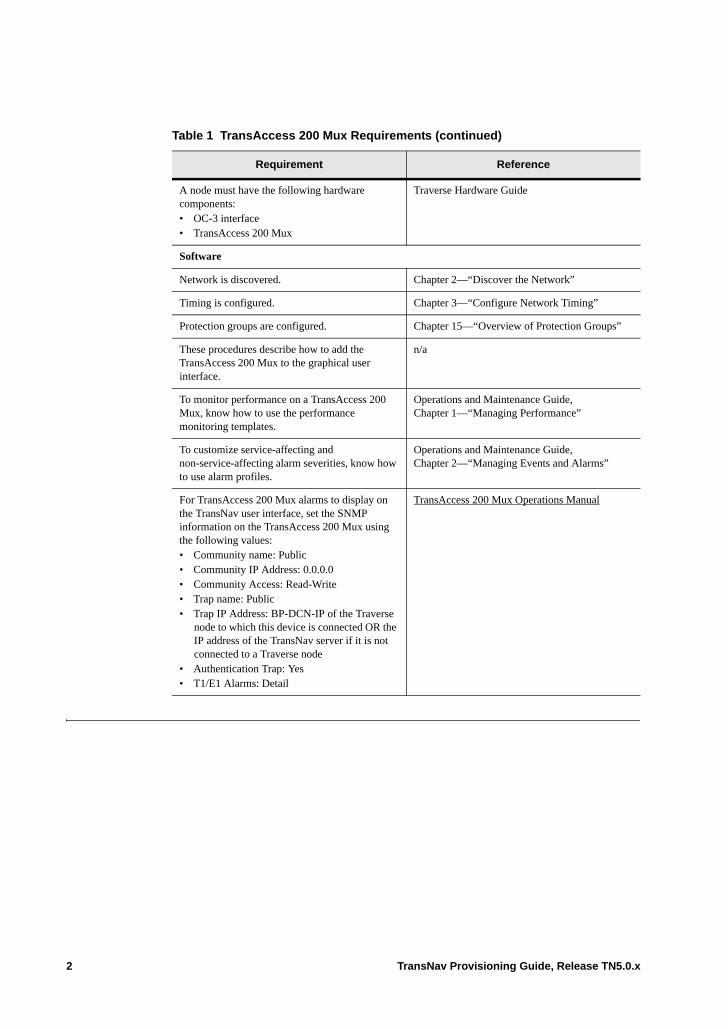
A node must have the following hardware components: • OC-3 interface• TransAccess 200 Mux
Traverse Hardware Guide
Software
Network is discovered. Chapter 2—“Discover the Network”
Timing is configured. Chapter 3—“Configure Network Timing”
Protection groups are configured. Chapter 15—“Overview of Protection Groups”
These procedures describe how to add the TransAccess 200 Mux to the graphical user interface.
n/a
To monitor performance on a TransAccess 200 Mux, know how to use the performance monitoring templates.
Operations and Maintenance Guide, Chapter 1—“Managing Performance”
To customize service-affecting and non-service-affecting alarm severities, know how to use alarm profiles.
Operations and Maintenance Guide, Chapter 2—“Managing Events and Alarms”
For TransAccess 200 Mux alarms to display on the TransNav user interface, set the SNMP information on the TransAccess 200 Mux using the following values:• Community name: Public• Community IP Address: 0.0.0.0• Community Access: Read-Write• Trap name: Public• Trap IP Address: BP-DCN-IP of the Traverse
node to which this device is connected OR the IP address of the TransNav server if it is not connected to a Traverse node
• Authentication Trap: Yes• T1/E1 Alarms: Detail
TransAccess 200 Mux Operations Manual
Table 1 TransAccess 200 Mux Requirements (continued)
Requirement Reference
2 TransNav Provisioning Guide, Release TN5.0.x
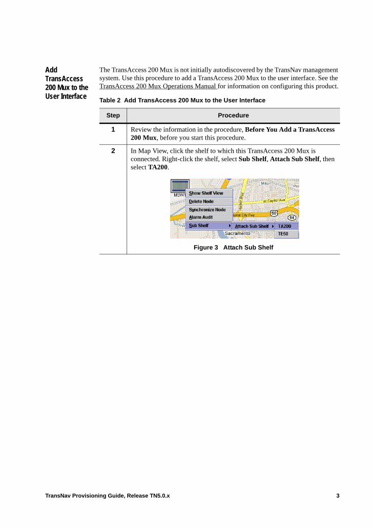
Add TransAccess 200 Mux to the User Interface
The TransAccess 200 Mux is not initially autodiscovered by the TransNav management system. Use this procedure to add a TransAccess 200 Mux to the user interface. See the TransAccess 200 Mux Operations Manual for information on configuring this product.
Table 2 Add TransAccess 200 Mux to the User Interface
Step Procedure
1 Review the information in the procedure, Before You Add a TransAccess 200 Mux, before you start this procedure.
2 In Map View, click the shelf to which this TransAccess 200 Mux is connected. Right-click the shelf, select Sub Shelf, Attach Sub Shelf, then select TA200.
Figure 3 Attach Sub Shelf
TransNav Provisioning Guide, Release TN5.0.x 3
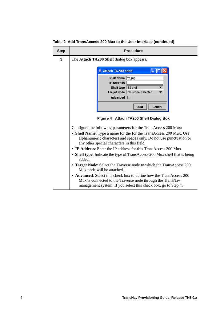
3 The Attach TA200 Shelf dialog box appears.
Figure 4 Attach TA200 Shelf Dialog Box
Configure the following parameters for the TransAccess 200 Mux:• Shelf Name: Type a name for the for the TransAccess 200 Mux. Use
alphanumeric characters and spaces only. Do not use punctuation or any other special characters in this field.
• IP Address: Enter the IP address for this TransAccess 200 Mux.• Shelf type: Indicate the type of TransAccess 200 Mux shelf that is being
added. • Target Node: Select the Traverse node to which the TransAccess 200
Mux node will be attached. • Advanced: Select this check box to define how the TransAccess 200
Mux is connected to the Traverse node through the TransNav management system. If you select this check box, go to Step 4.
Table 2 Add TransAccess 200 Mux to the User Interface (continued)
Step Procedure
4 TransNav Provisioning Guide, Release TN5.0.x
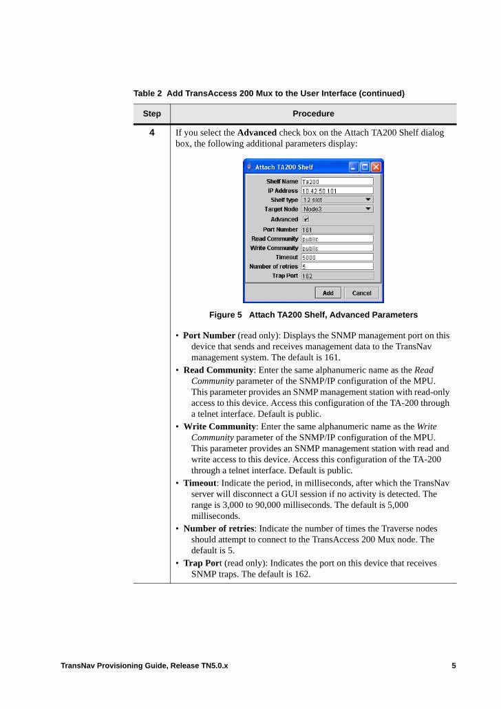
4 If you select the Advanced check box on the Attach TA200 Shelf dialog box, the following additional parameters display:
Figure 5 Attach TA200 Shelf, Advanced Parameters
• Port Number (read only): Displays the SNMP management port on this device that sends and receives management data to the TransNav management system. The default is 161.
• Read Community: Enter the same alphanumeric name as the Read Community parameter of the SNMP/IP configuration of the MPU. This parameter provides an SNMP management station with read-only access to this device. Access this configuration of the TA-200 through a telnet interface. Default is public.
• Write Community: Enter the same alphanumeric name as the Write Community parameter of the SNMP/IP configuration of the MPU. This parameter provides an SNMP management station with read and write access to this device. Access this configuration of the TA-200 through a telnet interface. Default is public.
• Timeout: Indicate the period, in milliseconds, after which the TransNav server will disconnect a GUI session if no activity is detected. The range is 3,000 to 90,000 milliseconds. The default is 5,000 milliseconds.
• Number of retries: Indicate the number of times the Traverse nodes should attempt to connect to the TransAccess 200 Mux node. The default is 5.
• Trap Port (read only): Indicates the port on this device that receives SNMP traps. The default is 162.
Table 2 Add TransAccess 200 Mux to the User Interface (continued)
Step Procedure
TransNav Provisioning Guide, Release TN5.0.x 5
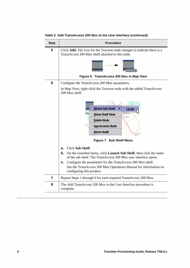
5 Click Add. The icon for the Traverse node changes to indicate there is a TransAccess 200 Mux shelf attached to this node.
Figure 6 TransAccess 200 Mux in Map View
6 Configure the TransAccess 200 Mux parameters.
In Map View, right-click the Traverse node with the added TransAccess 200 Mux shelf.
Figure 7 Sub Shelf Menu
a. Click Sub Shelf.
b. On the extended menu, click Launch Sub Shelf, then click the name of the sub shelf. The TransAccess 200 Mux user interface opens.
c. Configure the parameters for the TransAccess 200 Mux shelf. See the TransAccess 200 Mux Operations Manual for information on configuring this product.
7 Repeat Steps 1 through 6 for each required TransAccess 200 Mux.
8 The Add TransAccess 200 Mux to the User Interface procedure is complete.
Table 2 Add TransAccess 200 Mux to the User Interface (continued)
Step Procedure
6 TransNav Provisioning Guide, Release TN5.0.x
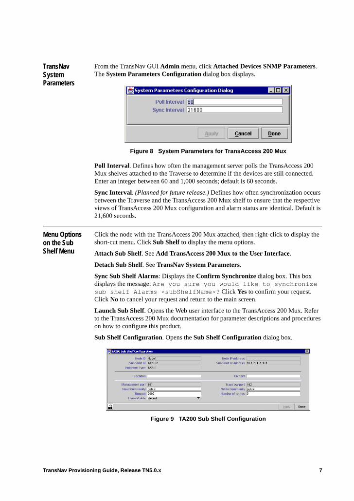
TransNav System Parameters
From the TransNav GUI Admin menu, click Attached Devices SNMP Parameters. The System Parameters Configuration dialog box displays.
Figure 8 System Parameters for TransAccess 200 Mux
Poll Interval. Defines how often the management server polls the TransAccess 200 Mux shelves attached to the Traverse to determine if the devices are still connected. Enter an integer between 60 and 1,000 seconds; default is 60 seconds.
Sync Interval. (Planned for future release.) Defines how often synchronization occurs between the Traverse and the TransAccess 200 Mux shelf to ensure that the respective views of TransAccess 200 Mux configuration and alarm status are identical. Default is 21,600 seconds.
Menu Options on the Sub Shelf Menu
Click the node with the TransAccess 200 Mux attached, then right-click to display the short-cut menu. Click Sub Shelf to display the menu options.
Attach Sub Shelf. See Add TransAccess 200 Mux to the User Interface.
Detach Sub Shelf. See TransNav System Parameters.
Sync Sub Shelf Alarms: Displays the Confirm Synchronize dialog box. This box displays the message: Are you sure you would like to synchronize sub shelf Alarms <subShelfName>? Click Yes to confirm your request. Click No to cancel your request and return to the main screen.
Launch Sub Shelf. Opens the Web user interface to the TransAccess 200 Mux. Refer to the TransAccess 200 Mux documentation for parameter descriptions and procedures on how to configure this product.
Sub Shelf Configuration. Opens the Sub Shelf Configuration dialog box.
Figure 9 TA200 Sub Shelf Configuration
TransNav Provisioning Guide, Release TN5.0.x 7
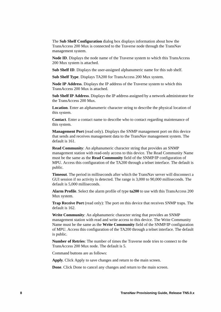
The Sub Shelf Configuration dialog box displays information about how the TransAccess 200 Mux is connected to the Traverse node through the TransNav management system.
Node ID. Displays the node name of the Traverse system to which this TransAccess 200 Mux system is attached.
Sub Shelf ID. Displays the user-assigned alphanumeric name for this sub shelf.
Sub Shelf Type. Displays TA200 for TransAccess 200 Mux system.
Node IP Address. Displays the IP address of the Traverse system to which this TransAccess 200 Mux is attached.
Sub Shelf IP Address. Displays the IP address assigned by a network administrator for the TransAccess 200 Mux.
Location. Enter an alphanumeric character string to describe the physical location of this system.
Contact. Enter a contact name to describe who to contact regarding maintenance of this system.
Management Port (read only). Displays the SNMP management port on this device that sends and receives management data to the TransNav management system. The default is 161.
Read Community: An alphanumeric character string that provides an SNMP management station with read-only access to this device. The Read Community Name must be the same as the Read Community field of the SNMP/IP configuration of MPU. Access this configuration of the TA200 through a telnet interface. The default is public.
Timeout. The period in milliseconds after which the TransNav server will disconnect a GUI session if no activity is detected. The range is 3,000 to 90,000 milliseconds. The default is 5,000 milliseconds.
Alarm Profile. Select the alarm profile of type ta200 to use with this TransAccess 200 Mux system.
Trap Receive Port (read only): The port on this device that receives SNMP traps. The default is 162.
Write Community: An alphanumeric character string that provides an SNMP management station with read and write access to this device. The Write Community Name must be the same as the Write Community field of the SNMP/IP configuration of MPU. Access this configuration of the TA200 through a telnet interface. The default is public.
Number of Retries: The number of times the Traverse node tries to connect to the TransAccess 200 Mux node. The default is 5.
Command buttons are as follows:
Apply. Click Apply to save changes and return to the main screen.
Done. Click Done to cancel any changes and return to the main screen.
8 TransNav Provisioning Guide, Release TN5.0.x
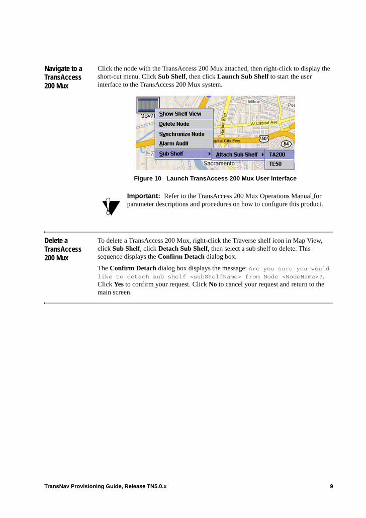
Navigate to a TransAccess 200 Mux
Click the node with the TransAccess 200 Mux attached, then right-click to display the short-cut menu. Click Sub Shelf, then click Launch Sub Shelf to start the user interface to the TransAccess 200 Mux system.
Figure 10 Launch TransAccess 200 Mux User Interface
Delete a TransAccess 200 Mux
To delete a TransAccess 200 Mux, right-click the Traverse shelf icon in Map View, click Sub Shelf, click Detach Sub Shelf, then select a sub shelf to delete. This sequence displays the Confirm Detach dialog box.
The Confirm Detach dialog box displays the message: Are you sure you would like to detach sub shelf <subShelfName> from Node <NodeName>?. Click Yes to confirm your request. Click No to cancel your request and return to the main screen.
Important: Refer to the TransAccess 200 Mux Operations Manual for parameter descriptions and procedures on how to configure this product.
TransNav Provisioning Guide, Release TN5.0.x 9

10 TransNav Provisioning Guide, Release TN5.0.x
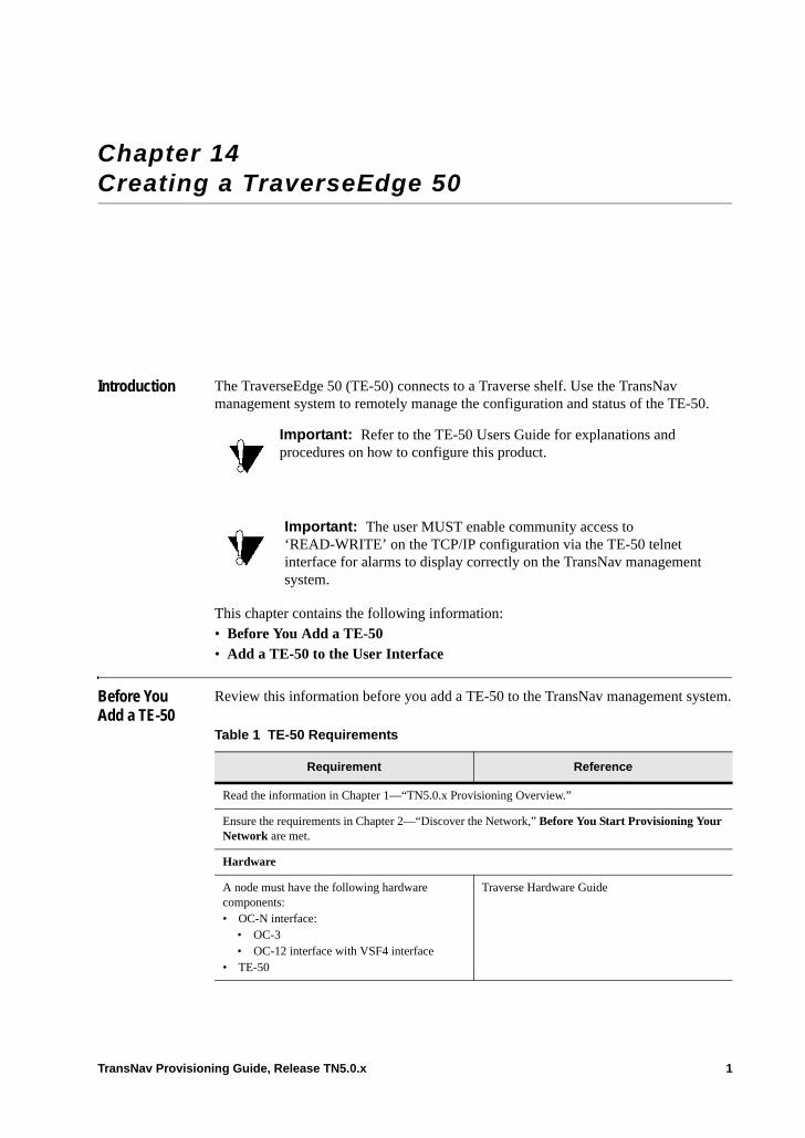
Chapter 14 Creating a TraverseEdge 50
Introduction The TraverseEdge 50 (TE-50) connects to a Traverse shelf. Use the TransNav management system to remotely manage the configuration and status of the TE-50.
This chapter contains the following information: • Before You Add a TE-50• Add a TE-50 to the User Interface
Before You Add a TE-50
Review this information before you add a TE-50 to the TransNav management system.
Important: Refer to the TE-50 Users Guide for explanations and procedures on how to configure this product.
Important: The user MUST enable community access to ‘READ-WRITE’ on the TCP/IP configuration via the TE-50 telnet interface for alarms to display correctly on the TransNav management system.
Table 1 TE-50 Requirements
Requirement Reference
Read the information in Chapter 1—“TN5.0.x Provisioning Overview.”
Ensure the requirements in Chapter 2—“Discover the Network,” Before You Start Provisioning Your Network are met.
Hardware
A node must have the following hardware components: • OC-N interface:
• OC-3• OC-12 interface with VSF4 interface
• TE-50
Traverse Hardware Guide
TransNav Provisioning Guide, Release TN5.0.x 1
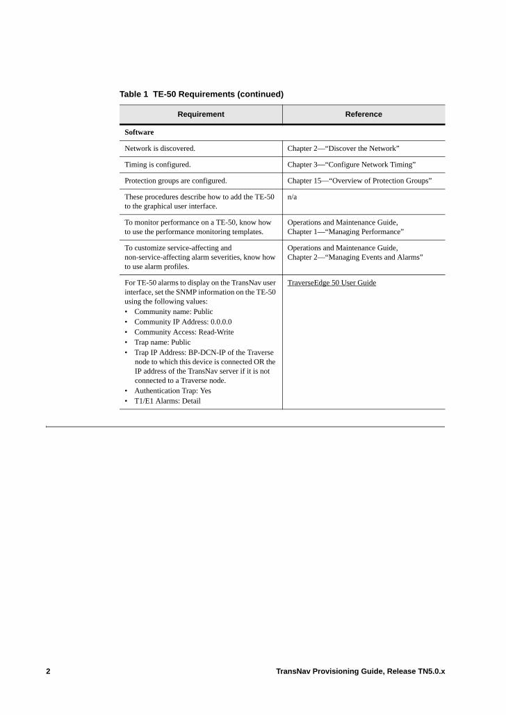
Software
Network is discovered. Chapter 2—“Discover the Network”
Timing is configured. Chapter 3—“Configure Network Timing”
Protection groups are configured. Chapter 15—“Overview of Protection Groups”
These procedures describe how to add the TE-50 to the graphical user interface.
n/a
To monitor performance on a TE-50, know how to use the performance monitoring templates.
Operations and Maintenance Guide, Chapter 1—“Managing Performance”
To customize service-affecting and non-service-affecting alarm severities, know how to use alarm profiles.
Operations and Maintenance Guide, Chapter 2—“Managing Events and Alarms”
For TE-50 alarms to display on the TransNav user interface, set the SNMP information on the TE-50 using the following values:• Community name: Public• Community IP Address: 0.0.0.0 • Community Access: Read-Write• Trap name: Public• Trap IP Address: BP-DCN-IP of the Traverse
node to which this device is connected OR the IP address of the TransNav server if it is not connected to a Traverse node.
• Authentication Trap: Yes• T1/E1 Alarms: Detail
TraverseEdge 50 User Guide
Table 1 TE-50 Requirements (continued)
Requirement Reference
2 TransNav Provisioning Guide, Release TN5.0.x
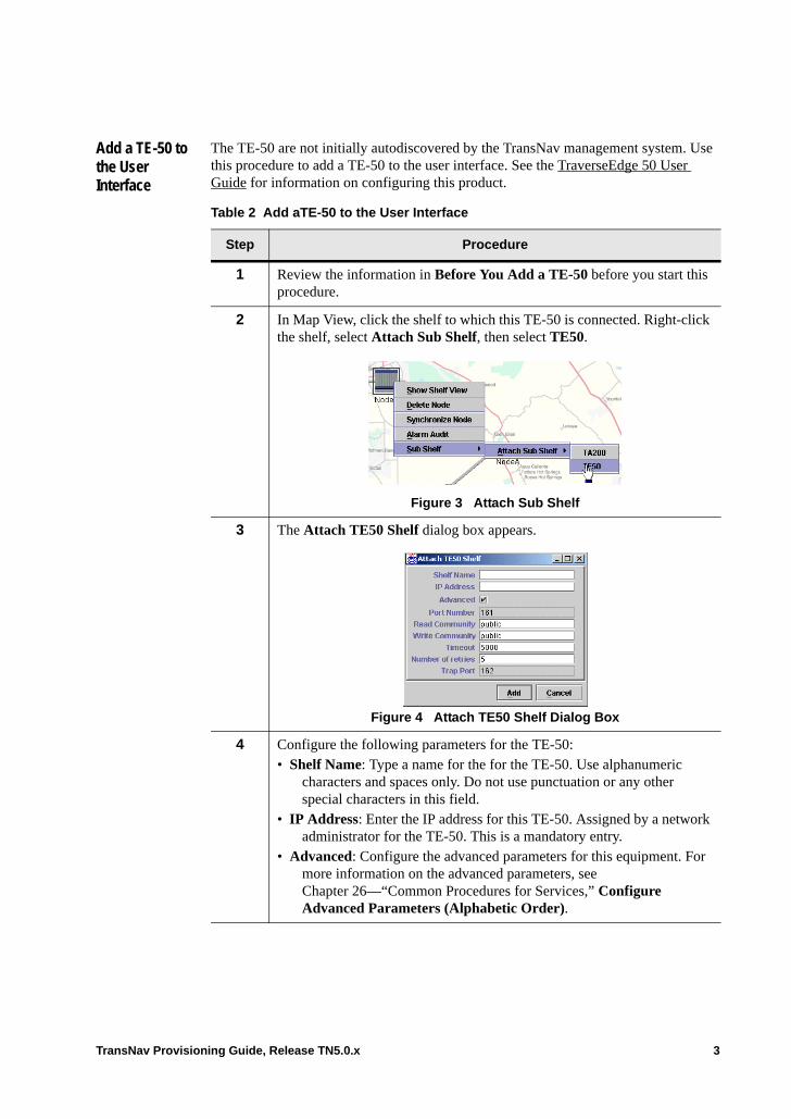
Add a TE-50 to the User Interface
The TE-50 are not initially autodiscovered by the TransNav management system. Use this procedure to add a TE-50 to the user interface. See the TraverseEdge 50 User Guide for information on configuring this product.
Table 2 Add aTE-50 to the User Interface
Step Procedure
1 Review the information in Before You Add a TE-50 before you start this procedure.
2 In Map View, click the shelf to which this TE-50 is connected. Right-click the shelf, select Attach Sub Shelf, then select TE50.
Figure 3 Attach Sub Shelf
3 The Attach TE50 Shelf dialog box appears.
Figure 4 Attach TE50 Shelf Dialog Box
4 Configure the following parameters for the TE-50:• Shelf Name: Type a name for the for the TE-50. Use alphanumeric
characters and spaces only. Do not use punctuation or any other special characters in this field.
• IP Address: Enter the IP address for this TE-50. Assigned by a network administrator for the TE-50. This is a mandatory entry.
• Advanced: Configure the advanced parameters for this equipment. For more information on the advanced parameters, see Chapter 26—“Common Procedures for Services,” Configure Advanced Parameters (Alphabetic Order).
TransNav Provisioning Guide, Release TN5.0.x 3

Delete a TE-50 To delete a TE-50, right-click the Traverse shelf icon in Map View, click Sub Shelf, click Detach Sub Shelf, then select a sub shelf to delete. This sequence displays the Confirm Detach dialog box.
The Confirm Detach dialog box displays the message: Are you sure you would like to detach sub shelf <subShelfName> from Node <NodeName>? Click Yes to confirm your request. Click No to cancel your request and return to the main screen.
TransNav System Parameters
From the Admin menu, click Attached Devices SNMP Parameters. The System Parameters dialog box displays.
Figure 15 System Parameters for TE-50
Poll Interval. Defines how often the management server polls the TE-50 shelves attached to that Traverse to determine if the devices are still connected. Enter an integer between 60 and 1000 seconds. The default is 60 seconds.
5 Click Add. The icon for the Traverse node changes to indicate there is a TE-50 shelf attached to this node.
Figure 5 TE-50 in Map View
6 Configure the TE-50 parameters.
In Map View, right-click the node with the added TE-50 shelf
a. Click Sub Shelf.
b. Configure the parameters for the TE-50 shelf. See the TraverseEdge 50 User Guide for information on configuring this product.
7 Repeat Steps 1 through 6 for each required TE-50.
8 The Add a TE-50 to the User Interface procedure is complete.
Table 2 Add aTE-50 to the User Interface (continued)
Step Procedure
4 TransNav Provisioning Guide, Release TN5.0.x
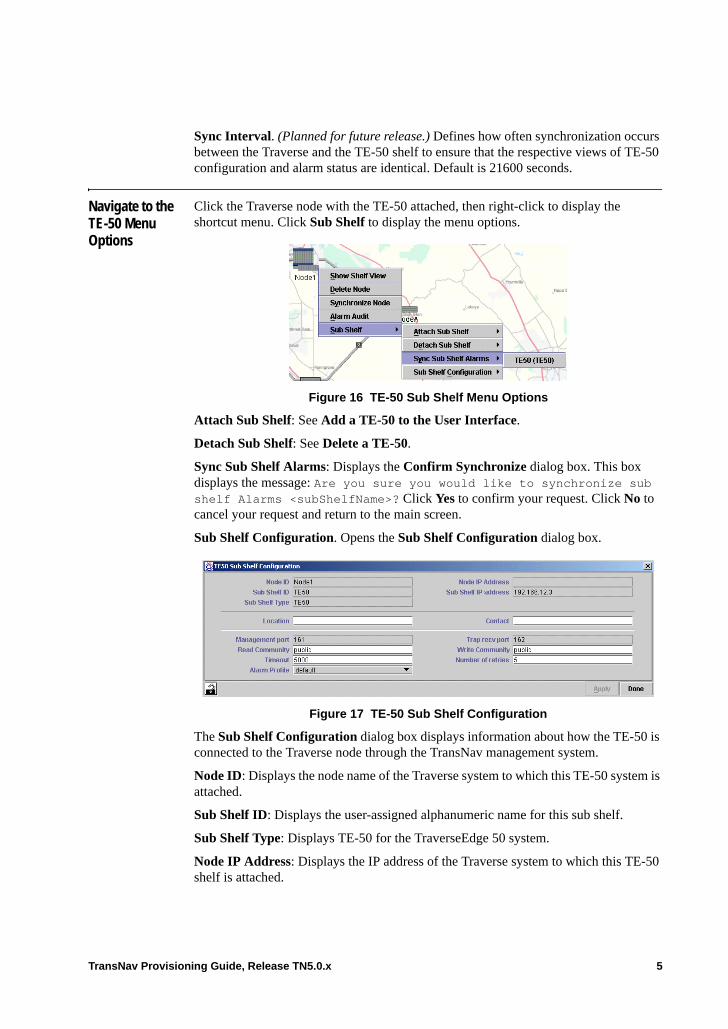
Sync Interval. (Planned for future release.) Defines how often synchronization occurs between the Traverse and the TE-50 shelf to ensure that the respective views of TE-50 configuration and alarm status are identical. Default is 21600 seconds.
Navigate to the TE-50 Menu Options
Click the Traverse node with the TE-50 attached, then right-click to display the shortcut menu. Click Sub Shelf to display the menu options.
Figure 16 TE-50 Sub Shelf Menu Options
Attach Sub Shelf: See Add a TE-50 to the User Interface.
Detach Sub Shelf: See Delete a TE-50.
Sync Sub Shelf Alarms: Displays the Confirm Synchronize dialog box. This box displays the message: Are you sure you would like to synchronize sub shelf Alarms <subShelfName>? Click Yes to confirm your request. Click No to cancel your request and return to the main screen.
Sub Shelf Configuration. Opens the Sub Shelf Configuration dialog box.
Figure 17 TE-50 Sub Shelf Configuration
The Sub Shelf Configuration dialog box displays information about how the TE-50 is connected to the Traverse node through the TransNav management system.
Node ID: Displays the node name of the Traverse system to which this TE-50 system is attached.
Sub Shelf ID: Displays the user-assigned alphanumeric name for this sub shelf.
Sub Shelf Type: Displays TE-50 for the TraverseEdge 50 system.
Node IP Address: Displays the IP address of the Traverse system to which this TE-50 shelf is attached.
TransNav Provisioning Guide, Release TN5.0.x 5
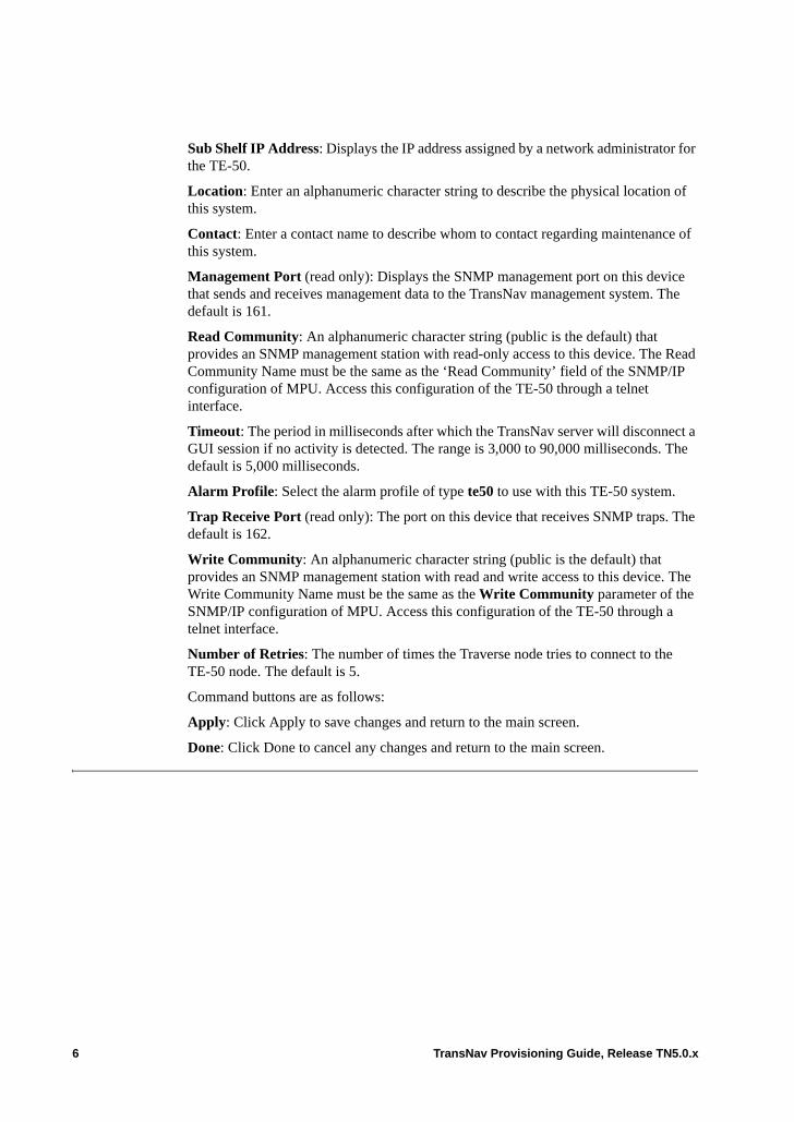
Sub Shelf IP Address: Displays the IP address assigned by a network administrator for the TE-50.
Location: Enter an alphanumeric character string to describe the physical location of this system.
Contact: Enter a contact name to describe whom to contact regarding maintenance of this system.
Management Port (read only): Displays the SNMP management port on this device that sends and receives management data to the TransNav management system. The default is 161.
Read Community: An alphanumeric character string (public is the default) that provides an SNMP management station with read-only access to this device. The Read Community Name must be the same as the ‘Read Community’ field of the SNMP/IP configuration of MPU. Access this configuration of the TE-50 through a telnet interface.
Timeout: The period in milliseconds after which the TransNav server will disconnect a GUI session if no activity is detected. The range is 3,000 to 90,000 milliseconds. The default is 5,000 milliseconds.
Alarm Profile: Select the alarm profile of type te50 to use with this TE-50 system.
Trap Receive Port (read only): The port on this device that receives SNMP traps. The default is 162.
Write Community: An alphanumeric character string (public is the default) that provides an SNMP management station with read and write access to this device. The Write Community Name must be the same as the Write Community parameter of the SNMP/IP configuration of MPU. Access this configuration of the TE-50 through a telnet interface.
Number of Retries: The number of times the Traverse node tries to connect to the TE-50 node. The default is 5.
Command buttons are as follows:
Apply: Click Apply to save changes and return to the main screen.
Done: Click Done to cancel any changes and return to the main screen.
6 TransNav Provisioning Guide, Release TN5.0.x
Chapter 15 Overview of Protection Groups
Introduction Depending on the network requirements, the Traverse system supports a selection of methods to protect traffic.
This chapter includes the following topics:• 1:N Equipment Protection• Optical GbE Port Protection• Carrier Ethernet Protection• Line Protection• Path Protection
All system components included are easily accessible and hot-swappable. Additionally, both hardware and software upgrades can be performed in-service without interruption to existing network traffic. This capability allows the transport network to expand gracefully as you add new customers and service requirement.
If you have configured a card as part of an equipment protection group, you can configure parameters only on the working card. Down arrows on selections are grayed out for parameters on the protecting card.
Parameters on a port on a protecting card are automatically set to those configured for the same port on the working card. For example, if Line Format is set to M23 for port 1, slot 2 (the working card), Line Format will also be set to M23 for port 1, slot 1 (the protecting card).
TransNav Provisioning Guide, Release TN5.0.x 1
1:N Equipment Protection
Equipment protection groups use one card to provide redundancy for one or more of equal type. The Traverse supports the following types of equipment protection:• 1:1 equipment protection: One card physically protects an adjacent card (DS1, DS3,
DS3-CC, DS3-TMX, E1, E3-CC, NGE, NGE Plus, EoPDH, 10GbE, GbE-10, or UTMX cards).
Note: VTX/VCX integrated cards are not adjacent.
Note: 1:1 equipment protection between NGE and EoPDH cards is not supported.
NGE, NGE Plus and EoPDH cards using the Ethernet electrical connector module (ECM) provide equipment protection for the electrical ports only. For protection of the optical ports on these cards, see Optical GbE Port Protection.
• 1:2 equipment protection: One card protects up to two adjacent cards (DS3-CC, DS3-TMX, DS1, E1,E3, UTMX-24, UTMX-48, VT/TU 5G Switch, VT-HD 40G Switch, and VTX/VCX integrated cards).
• 1:N equipment protection, where:– One card protects all remaining cards and cards need not be adjacent.
- N = 1 to 2 for VT/TU 5G Switch on ADM shelf - N = 1 to 9 for VT/TU 5G Switch on DCS-384 shelf- N = 1 to ?? for VT-HD 40G Switch on DCS-768 shelf (Protect card must
be on left; working card on right)– One card protects all remaining adjacent cards.
- N = 1 to 12 for DS3 Transmux protection groups for high-density optical transmux applications (STS1-TMX)
– One card protects all remaining cards. - N = 1 to 4 for UTMX protection groups for high-density optical transmux
applications (STS1-TMX)
To create equipment protection groups, see Chapter 18—“Creating Equipment Protection Groups.”
Optical GbE Port Protection
With an optical coupler/splitter cable, protection extends to the optical (GbE or 10GbE) ports on NGE, NGE Plus, 1-port GbE, 10-port GbE, or EoPDH cards in a 1:1 equipment protection group. Use the optical splitter/coupler to bridge the signal from both the working and protecting card (of like type) to provide 1:1 optical equipment protection for these GbE ports.
There is one optical link from the customer premise equipment (CPE) to the coupler/splitter, connecting the CPE to the working card. The splitter sends a copy of the optical signal to both the working and protecting cards in the equipment protection group. The coupler receives a signal from both of the cards, combines them, and sends the composite signal—effectively the signal from the working (active) card—to the CPE.
On the working card of the protection group, the optical transmitters are up (laser on), while on the protecting (standby) card, the optical transmitters are forced down (laser off). Upon an equipment protection switch, when the card transitions from working to protecting or vice versa, its optical ports are automatically brought down or up, as appropriate.
2 TransNav Provisioning Guide, Release TN5.0.x
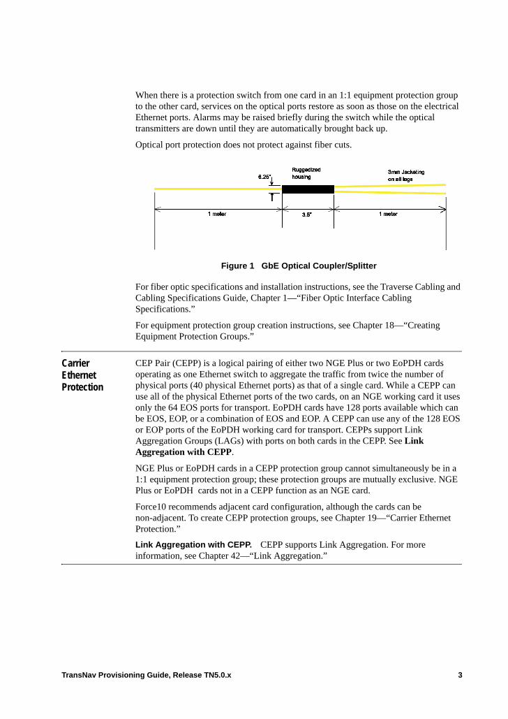
When there is a protection switch from one card in an 1:1 equipment protection group to the other card, services on the optical ports restore as soon as those on the electrical Ethernet ports. Alarms may be raised briefly during the switch while the optical transmitters are down until they are automatically brought back up.
Optical port protection does not protect against fiber cuts.
Figure 1 GbE Optical Coupler/Splitter
For fiber optic specifications and installation instructions, see the Traverse Cabling and Cabling Specifications Guide, Chapter 1—“Fiber Optic Interface Cabling Specifications.”
For equipment protection group creation instructions, see Chapter 18—“Creating Equipment Protection Groups.”
Carrier Ethernet Protection
CEP Pair (CEPP) is a logical pairing of either two NGE Plus or two EoPDH cards operating as one Ethernet switch to aggregate the traffic from twice the number of physical ports (40 physical Ethernet ports) as that of a single card. While a CEPP can use all of the physical Ethernet ports of the two cards, on an NGE working card it uses only the 64 EOS ports for transport. EoPDH cards have 128 ports available which can be EOS, EOP, or a combination of EOS and EOP. A CEPP can use any of the 128 EOS or EOP ports of the EoPDH working card for transport. CEPPs support Link Aggregation Groups (LAGs) with ports on both cards in the CEPP. See Link Aggregation with CEPP.
NGE Plus or EoPDH cards in a CEPP protection group cannot simultaneously be in a 1:1 equipment protection group; these protection groups are mutually exclusive. NGE Plus or EoPDH cards not in a CEPP function as an NGE card.
Force10 recommends adjacent card configuration, although the cards can be non-adjacent. To create CEPP protection groups, see Chapter 19—“Carrier Ethernet Protection.”
Link Aggregation with CEPP. CEPP supports Link Aggregation. For more information, see Chapter 42—“Link Aggregation.”
TransNav Provisioning Guide, Release TN5.0.x 3
Line Protection Line protection switching is a traffic protection mechanism based on SONET/SDH line level indications. A line is the transmission medium and the associated equipment that transports information between two network elements: one which originates the line signal and one that terminates it. Line protection switching is a protection mechanism coordinated by the nodes on either side of the failure condition using the protection switching signaling protocol.
1+1 APS/MSP protection groups. The APS/MSP protocol is carried in the K1 and K2 bits in the SONET/SDH signal between nodes in a bi-directional mode. The APS/MSP controllers at the line termination use the channel to exchange requests and acknowledgement for protection switching actions.
1+1 APS/MSP uses both the working and the protect fibers to send traffic simultaneously to the next node. That is, the system duplicates the traffic and sends it over both the working and the protect fibers at the same time.
With this protection mechanism, when the system detects a failure the next node switches to accept traffic from the standby path. The link remains unprotected until service is restored on the working link.
To create a 1+1 APS/MSP protection group, see Chapter 20—“Creating a 1+1 APS/MSP Protection Group.”
Optimized protection switching. The Traverse system also supports 1+1 bi-directional optimized protections switching per ITU-T G.783 Annex B.
To create an optimized protection group, see Chapter 23—“Creating a 1+1 Optimized Protection Group.”
BLSR . Bi-directional Line Switched Ring (BLSR) provides geographically diverse paths for each service using a self-healing closed loop technology to protect against fiber cuts and node failures. Protection switching is performed at the Line layer of the SONET/SDH frame.
MS-SPRing . Multiplex Section Shared Protection Ring (MS-SPRing) provides geographically diverse paths for each service using a self-healing closed loop technology to protect against fiber cuts and node failures. Protection switching is performed at the multiplex section layer of the STM frame.
To create a BLSR or MS-SPRing protection group, see Chapter 16—“Creating a BLSR/MS-SPRing Protection Group.”
4 TransNav Provisioning Guide, Release TN5.0.x
Path Protection
Path protection switching is a traffic protection mechanism based on SONET/SDH path level indications. Path protection the logical end-to-end path of traffic through a network.
1+1 path protection. This protection mechanism uses one SONET/SDH of any bandwidth to protect another of the same bandwidth. In a Traverse network, use a 1+1 path protection group to protect the transport of DS1 and VT services.
1+1 path protection uses one STM of any bandwidth to protect another of the same bandwidth. In a Traverse network, use a 1+1 path protection group to protect the transport of E1, VC11, and VC12 services.
To create 1+1 path protection groups, see Chapter 21—“Creating a 1+1 Path Protection Group.”
UPSR or SNCP Ring. This type of protection scheme requires two fibers to carry traffic in opposite directions around a fiber ring. Protection switching is performed at the path level. To provide survivability, traffic from the tributary side is bridged into both the working and protecting channels at the source. Path selection at the destination chooses the best quality signal (working or protecting) before dropping it from the ring.
To create UPSR or SNCP Ring protection groups, see Chapter 17—“Creating and Maintaining UPSR or SNCP Ring Protection Groups.”
TransNav Provisioning Guide, Release TN5.0.x 5

6 TransNav Provisioning Guide, Release TN5.0.x
Chapter 16 Creating a BLSR/MS-SPRing Protection Group
Introduction A BLSR/MS-SPRing protection group provides geographically diverse paths for each service using a self-healing closed loop technology to protect against fiber cuts and node failures. Protection switching is performed at the line layer of the SONET and the multiplex section of the SDH frame.
The Traverse supports for 2-fiber (2F) BLSR/MS-SPRing. A 2F BLSR/2F MS-SP Ring offers substantial capacity advantages in interoffice and access networks that have distributed mesh traffic patterns because of its ability to reuse bandwidth, as traffic is added and dropped at various locations around the ring.• Example of a BLSR/ MS-SPRing• Before You Create a BLSR or MS-SPRing• Guidelines to Create a BLSR or MS-SPRing Protection Group• Create a BLSR or MS-SPRing Protection Group
The Traverse system supports up to 16 nodes in a BLSR or MS-SPRing protection group.
The Traverse supports squelching. Nodes adjacent to a ring failure replace non-restorable traffic with a path layer alarm indication signal (AIS) to notify the far-end node of the interruption in service. The squelching feature automatically generates squelch tables; no manual record keeping is required. For information on the squelch table, see Viewing the Squelch Table.
This section contains information on the following topics:• Operations Menu• Protection Switch Request Priorities• Viewing the Squelch Table• Updating a Topology (Adding a Node)
TransNav Provisioning Guide, Release TN5.0.x 1
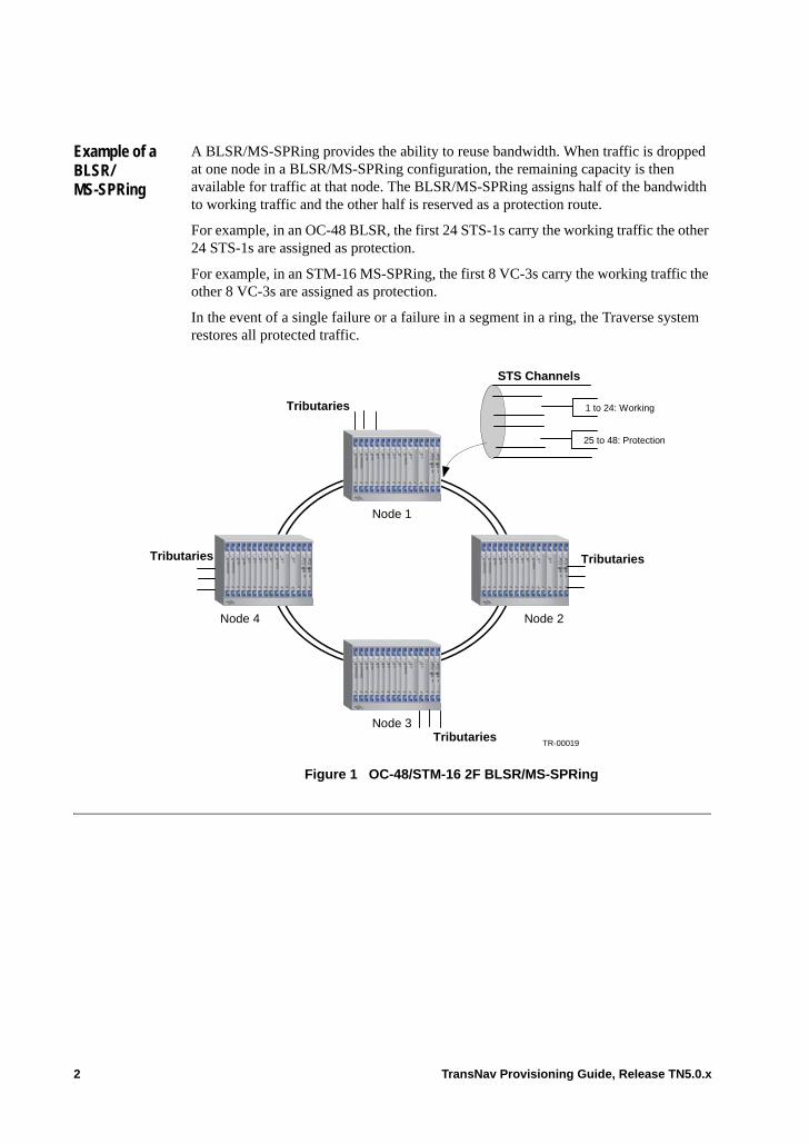
Example of a BLSR/ MS-SPRing
A BLSR/MS-SPRing provides the ability to reuse bandwidth. When traffic is dropped at one node in a BLSR/MS-SPRing configuration, the remaining capacity is then available for traffic at that node. The BLSR/MS-SPRing assigns half of the bandwidth to working traffic and the other half is reserved as a protection route.
For example, in an OC-48 BLSR, the first 24 STS-1s carry the working traffic the other 24 STS-1s are assigned as protection.
For example, in an STM-16 MS-SPRing, the first 8 VC-3s carry the working traffic the other 8 VC-3s are assigned as protection.
In the event of a single failure or a failure in a segment in a ring, the Traverse system restores all protected traffic.
Figure 1 OC-48/STM-16 2F BLSR/MS-SPRing
25 to 48: Protection
TR-00019
1 to 24: Working
Node 2Node 4
Node 3
Node 1
Tributaries
Tributaries
Tributaries
Tributaries
STS Channels
2 TransNav Provisioning Guide, Release TN5.0.x
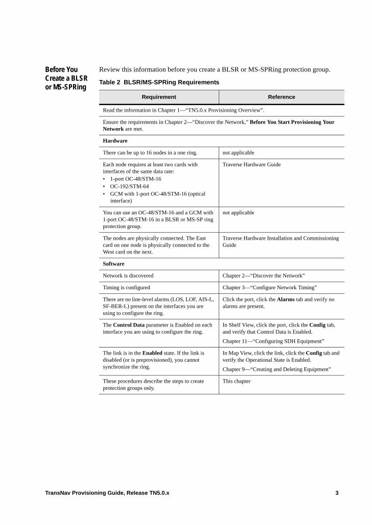
Before You Create a BLSR or MS-SPRing
Review this information before you create a BLSR or MS-SPRing protection group.
Table 2 BLSR/MS-SPRing Requirements
Requirement Reference
Read the information in Chapter 1—“TN5.0.x Provisioning Overview”.
Ensure the requirements in Chapter 2—“Discover the Network,” Before You Start Provisioning Your Network are met.
Hardware
There can be up to 16 nodes in a one ring. not applicable
Each node requires at least two cards with interfaces of the same data rate:• 1-port OC-48/STM-16• OC-192/STM-64• GCM with 1-port OC-48/STM-16 (optical
interface)
Traverse Hardware Guide
You can use an OC-48/STM-16 and a GCM with 1-port OC-48/STM-16 in a BLSR or MS-SP ring protection group.
not applicable
The nodes are physically connected. The East card on one node is physically connected to the West card on the next.
Traverse Hardware Installation and Commissioning Guide
Software
Network is discovered Chapter 2—“Discover the Network”
Timing is configured Chapter 3—“Configure Network Timing”
There are no line-level alarms (LOS, LOF, AIS-L, SF-BER-L) present on the interfaces you are using to configure the ring.
Click the port, click the Alarms tab and verify no alarms are present.
The Control Data parameter is Enabled on each interface you are using to configure the ring.
In Shelf View, click the port, click the Config tab, and verify that Control Data is Enabled.
Chapter 11—“Configuring SDH Equipment”
The link is in the Enabled state. If the link is disabled (or is preprovisioned), you cannot synchronize the ring.
In Map View, click the link, click the Config tab and verify the Operational State is Enabled.
Chapter 9—“Creating and Deleting Equipment”
These procedures describe the steps to create protection groups only.
This chapter
TransNav Provisioning Guide, Release TN5.0.x 3
Guidelines to Create a BLSR or MS-SPRing Protection Group
A single Traverse 2000 node supports the following numbers of BLSR or MS-SP Ring protection groups:• Up to four on OC-192 or STM-64 rings• Up to nine on OC-48 or STM-16 rings
A single Traverse 1600 node supports the following numbers of BLSR or MS-SP Ring protection groups:• Up to three on OC-192 or STM-64 rings• Up to seven on OC-48 or STM-16 rings
There can be up to 16 nodes in a 2F BLSR or MS-SP Ring.
Note: BLSR cannot be configured on 2-port OC-48 or STM-16 rings.
Ports in a BLSR or MS-SP ring protection group can only be part of that protection group. The ports cannot be part of another protection group.
The East card on one node is physically connected to the West port on the next.
The order of entry of nodes must be from East to West around the ring. That is, there must be a link from the East port of node n to the West port of node n+1 in the list.
4 TransNav Provisioning Guide, Release TN5.0.x
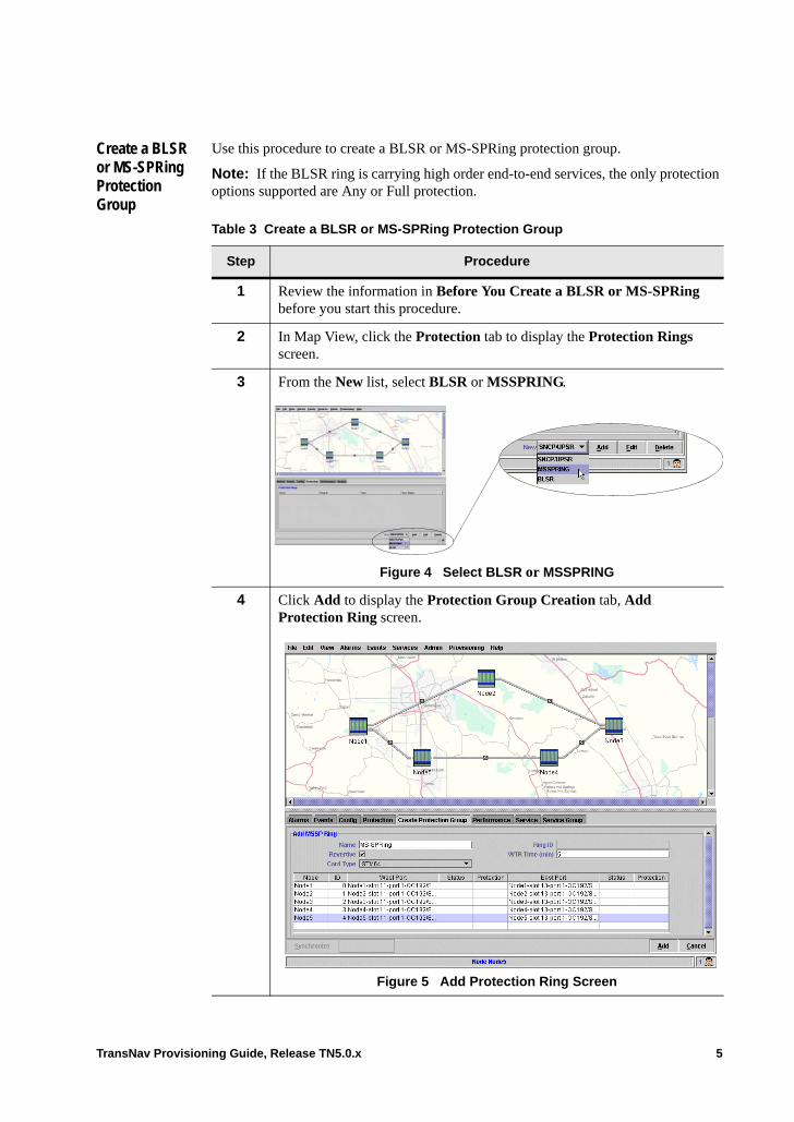
Create a BLSR or MS-SPRing Protection Group
Use this procedure to create a BLSR or MS-SPRing protection group.
Note: If the BLSR ring is carrying high order end-to-end services, the only protection options supported are Any or Full protection.
Table 3 Create a BLSR or MS-SPRing Protection Group
Step Procedure
1 Review the information in Before You Create a BLSR or MS-SPRing before you start this procedure.
2 In Map View, click the Protection tab to display the Protection Rings screen.
3 From the New list, select BLSR or MSSPRING.
Figure 4 Select BLSR or MSSPRING
4 Click Add to display the Protection Group Creation tab, Add Protection Ring screen.
Figure 5 Add Protection Ring Screen
TransNav Provisioning Guide, Release TN5.0.x 5
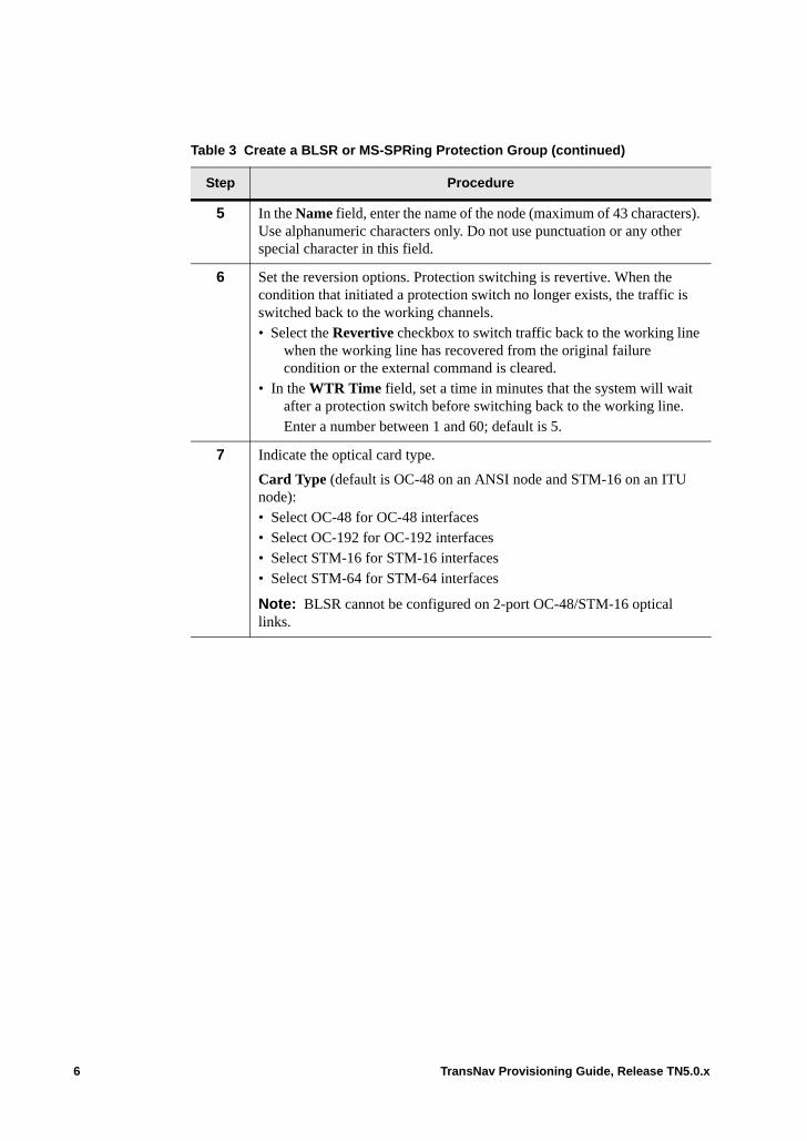
5 In the Name field, enter the name of the node (maximum of 43 characters). Use alphanumeric characters only. Do not use punctuation or any other special character in this field.
6 Set the reversion options. Protection switching is revertive. When the condition that initiated a protection switch no longer exists, the traffic is switched back to the working channels.• Select the Revertive checkbox to switch traffic back to the working line
when the working line has recovered from the original failure condition or the external command is cleared.
• In the WTR Time field, set a time in minutes that the system will wait after a protection switch before switching back to the working line.Enter a number between 1 and 60; default is 5.
7 Indicate the optical card type.
Card Type (default is OC-48 on an ANSI node and STM-16 on an ITU node):• Select OC-48 for OC-48 interfaces• Select OC-192 for OC-192 interfaces• Select STM-16 for STM-16 interfaces• Select STM-64 for STM-64 interfaces
Note: BLSR cannot be configured on 2-port OC-48/STM-16 optical links.
Table 3 Create a BLSR or MS-SPRing Protection Group (continued)
Step Procedure
6 TransNav Provisioning Guide, Release TN5.0.x

8 Add nodes to the ring. In Map View, click a node to add it to the ring. The nodes are displayed on the screen as you select them from Map View.
Figure 6 West and East Ports for BSLR/MS-SPRing
The system automatically assigns IDs consecutively beginning with “0” for the first node assigned to the ring. You can manually assign a node ID by selecting a number (0 through 15) from the ID list. Node IDs are not required to be consecutive, but a node ID can be used only once in a ring.
From the ID list, select a node identification (ID) number.
9 For each node in the ring (Node column), select a West port from the menu in the West Port column.
The West port of a node is physically connected to the East port of another node.
10 For each node in the ring (Node column), select an East port from the menu in the East Port column.
The East and West ports must be on separate cards in the shelf.
11 Indicate the Wait to Restore time in minutes.
WTR Time (min): The range is 5 to 12; default is 5. If the problem that caused the protection switch clears before the time specified in this parameter, you can restore the traffic to the working port immediately.
12 On the Add Protection Group screen, click Add.
13 In the Synchronize Protection Group dialog box, click Yes to propagate protection group information to all nodes in the ring.
Note: If your system has multiple servers, synchronization must be done from the Primary server only.
Table 3 Create a BLSR or MS-SPRing Protection Group (continued)
Step Procedure
TransNav Provisioning Guide, Release TN5.0.x 7
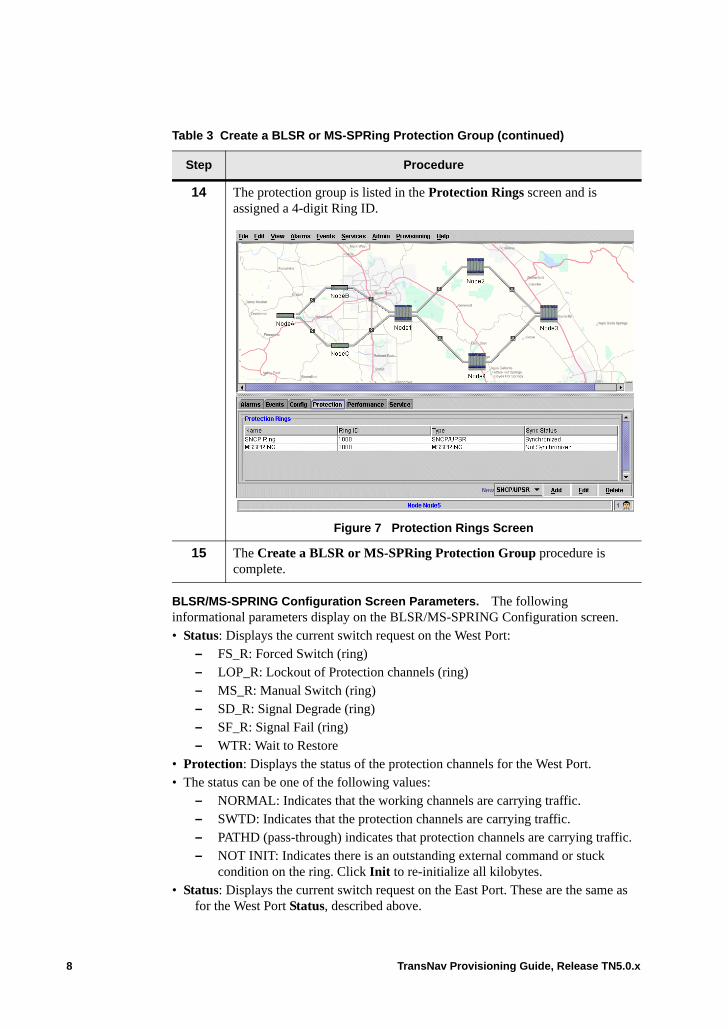
BLSR/MS-SPRING Configuration Screen Parameters. The following informational parameters display on the BLSR/MS-SPRING Configuration screen. • Status: Displays the current switch request on the West Port:
– FS_R: Forced Switch (ring)– LOP_R: Lockout of Protection channels (ring)– MS_R: Manual Switch (ring)– SD_R: Signal Degrade (ring)– SF_R: Signal Fail (ring)– WTR: Wait to Restore
• Protection: Displays the status of the protection channels for the West Port.• The status can be one of the following values:
– NORMAL: Indicates that the working channels are carrying traffic.– SWTD: Indicates that the protection channels are carrying traffic.– PATHD (pass-through) indicates that protection channels are carrying traffic.– NOT INIT: Indicates there is an outstanding external command or stuck
condition on the ring. Click Init to re-initialize all kilobytes.• Status: Displays the current switch request on the East Port. These are the same as
for the West Port Status, described above.
14 The protection group is listed in the Protection Rings screen and is assigned a 4-digit Ring ID.
Figure 7 Protection Rings Screen
15 The Create a BLSR or MS-SPRing Protection Group procedure is complete.
Table 3 Create a BLSR or MS-SPRing Protection Group (continued)
Step Procedure
8 TransNav Provisioning Guide, Release TN5.0.x

• Protection: See the definition for the West Port Protection, described above.
Command buttons are as follows:• Add: Add the protection group to the network configuration. A dialog box displays
that reads, “Would you like to synchronize the new Protection Group?” Click Yes to propagate the new protection group information to all nodes in the ring, or click No. The protection group is listed on the Protection tab.
Note: If your system has multiple servers, synchronization must be done from the Primary server only.
• Cancel: Cancel the protection group information.• Synchronize: There are two boxes in the lower left side of the Protection Group tab;
one for Synchronize, the second for Not Synchronized/Synchronized. If the second box displays Not Synchronized, click Synchronize to propagate the information so that all nodes know they belong to a protection group.
• Init: Re-initializes the kilobytes on all the facilities involved in the protection group. Click Init to clear any pending external commands or stuck conditions.
• Add Node: Add a new node to the existing ring.• Remove Node: Remove a node from the existing ring.
Operations Menu
In the {BLSR | MS-SP Ring} Configuration screen, right-click a row to display commands specific to a BLSR or MS-SP ring.
Figure 8 Operations Menu
Menu selections are as follows:• Remove: Remove the selected node from the ring.• Squelch Table: At each node, use the squelch table to specify the source and
destination points of every provisioned path in the ring. See Viewing the Squelch Table.
• Clear. See Clear user-initiated switch commands from the selected port. This also clears the Wait to Restore state of the selected node.
• Lockout Protecting Ring: Prevent protection switches anywhere in the ring. If any working traffic is using the protection channels on any span, this command causes traffic to switch back to the working channels regardless of the condition of the working channels.
TransNav Provisioning Guide, Release TN5.0.x 9
• Forced Switch–Ring (FS_R): Perform the ring switch from the working channels to the protection channels for the span between the node where the command is initiated and the adjacent node to which the command is destined. This switch occurs regardless of the state of the protection channels, unless the protection channels are satisfying a higher priority request.
• Manual Switch–Ring (MS_R): Perform the ring switch from the working channels to the protection channels for the span between the node where the command is initiated and the node to which the command is destined. This switch occurs if the protection channels to be used are operating at a BER better than the signal degrade threshold and are not satisfying an equal or higher priority request (including failure of the protection channels).
Protection Switch Request Priorities
Switching request priorities (from highest to lowest) for BLSR or MS-SP ring protection are:• Clear: User-initiated action.• Lockout of Protection (ring): User-initiated action.• Forced Switch (ring): User-initiated protection switch. • Signal Fail (ring): System-initiated protection switch. An SF is defined as a hard
failure caused by a Loss of Signal (LOS), a line BER exceeding a preselected threshold, a line AIS, or some other hard failure.
• Signal Degrade (ring): System-initiated protection switch. An SD is defined as a soft failure caused by a BER exceeding a preselected threshold.
• Manual Switch (ring): User-initiated protection switch.• Wait to Restore (WTR): User-configurable setting. This request is issued when
working channels meet the restore threshold after an SD or SF condition.• No Request.
10 TransNav Provisioning Guide, Release TN5.0.x
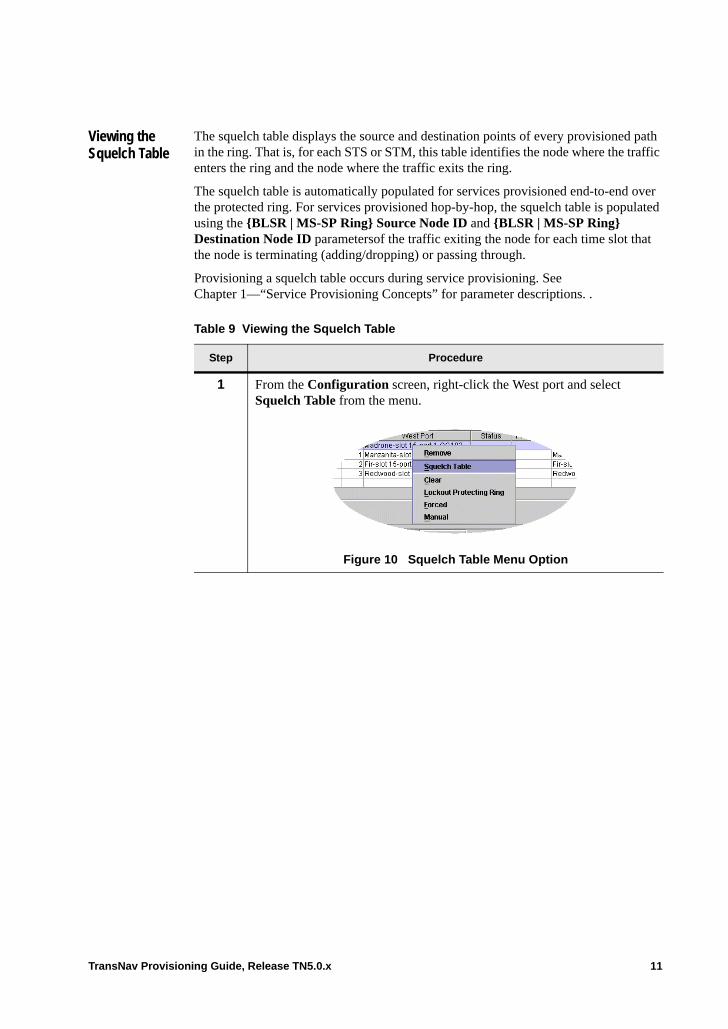
Viewing the Squelch Table
The squelch table displays the source and destination points of every provisioned path in the ring. That is, for each STS or STM, this table identifies the node where the traffic enters the ring and the node where the traffic exits the ring.
The squelch table is automatically populated for services provisioned end-to-end over the protected ring. For services provisioned hop-by-hop, the squelch table is populated using the {BLSR | MS-SP Ring} Source Node ID and {BLSR | MS-SP Ring} Destination Node ID parametersof the traffic exiting the node for each time slot that the node is terminating (adding/dropping) or passing through.
Provisioning a squelch table occurs during service provisioning. See Chapter 1—“Service Provisioning Concepts” for parameter descriptions. .
Table 9 Viewing the Squelch Table
Step Procedure
1 From the Configuration screen, right-click the West port and select Squelch Table from the menu.
Figure 10 Squelch Table Menu Option
TransNav Provisioning Guide, Release TN5.0.x 11
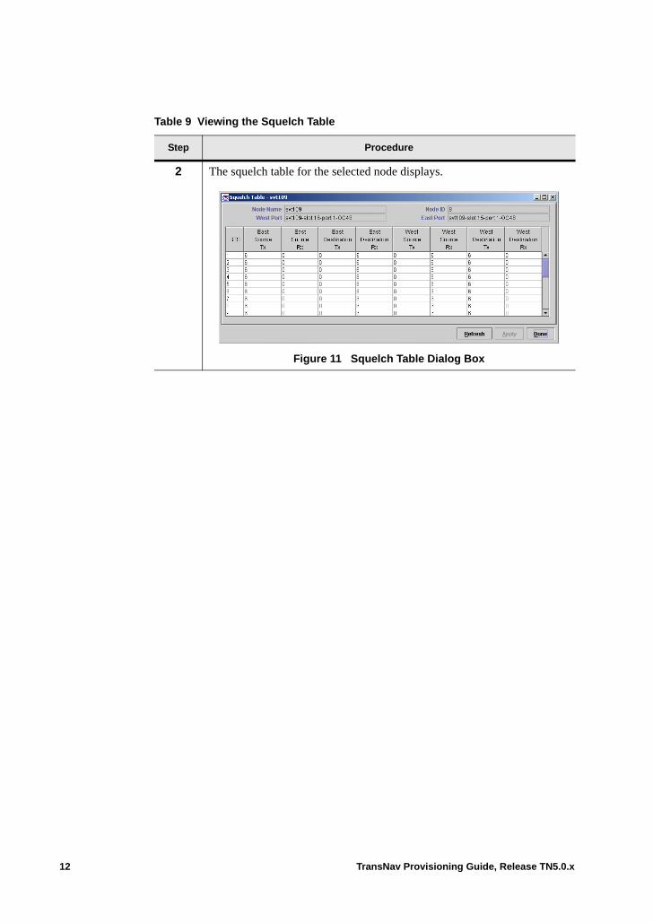
2 The squelch table for the selected node displays.
Figure 11 Squelch Table Dialog Box
Table 9 Viewing the Squelch Table
Step Procedure
12 TransNav Provisioning Guide, Release TN5.0.x
Updating a Topology (Adding a Node)
For information on the steps required to update a topology, see See Chapter 17—“Creating and Maintaining UPSR or SNCP Ring Protection Groups,” Updating a Topology (Adding a Node).
3 The following informational parameters display:
Node Name: Displays the name of the selected node.
Node ID: Displays the BLSR or MS-SPRing node identification of the selected node. The Node ID is assigned by the system when you create the protection group (ID column on the Configuration screen).
West Port: Displays the West port on the selected node for the protection group.
East Port: Displays the East port on the selected node for the protection group.
For each path (system-specified based on bandwidth of the fiber) entering and exiting that node, this table identifies:• East Source Tx: Displays the {BLSR | MS-SP Ring} Node ID where
the traffic on this path enters the ring. Unidirectional services display only the transmit direction.
• East Source Rx: For bidirectional services, displays the {BLSR | MS-SP Ring} Node ID where the traffic on this path exits the ring.
• East Destination Tx: Displays the {BLSR | MS-SP Ring} Node ID where the traffic on this path enters the ring. Unidirectional services display only the transmit direction.
• East Destination Rx: For bidirectional services, displays the {BLSR | MS-SP Ring} Node ID where the traffic on this path exits the ring.
• West Source Tx: For bidirectional services, displays the {BLSR | MS-SP Ring} Node ID where the traffic on this path enters the ring. Unidirectional services display only the transmit direction.
• West Source Rx: Displays the {BLSR | MS-SP Ring} Node ID where the traffic on this path exits the ring.
• West Destination Tx: For bidirectional services, displays the {BLSR | MS-SP Ring} Node ID: Indicates where the traffic on this path enters the ring. Unidirectional services display only the transmit direction.
West Destination Rx: Displays the {BLSR | MS-SP Ring} Node ID where the traffic on this path exits the ring.
Table 9 Viewing the Squelch Table
Step Procedure
TransNav Provisioning Guide, Release TN5.0.x 13

14 TransNav Provisioning Guide, Release TN5.0.x
Chapter 17 Creating and Maintaining UPSR or SNCP Ring Protection Groups
Introduction A Uni-directional Path Switched Ring (UPSR) is a self-healing closed loop topology that protects against fiber cuts and node failures by providing duplicate, geographically diverse paths for each service.
Subnetwork Connection Protection (SNCP) provides end-to-end path protection in a ring topology.
This chapter contains information on creating a UPSR (for SDH, an UPSR ring) protection group.• Example of a UPSR or an SNCP Ring• Before You Create a UPSR or SNCP Ring Protection Group• Guidelines to Create a UPSR or SNCP Ring• Create a UPSR or SNCP Ring Protection Group
The Traverse system supports up to 16 nodes in a UPSR or SNCP ring. This chapter contains information on the following topics:• SNCP/UPSR Protection Switch Commands• Synchronizing, Editing, and Deleting Configured Protection Rings• Updating a Topology (Adding a Node)• Conducting Maintenance on a UPSR or SNCP Ring
TransNav Provisioning Guide, Release TN5.0.x 1
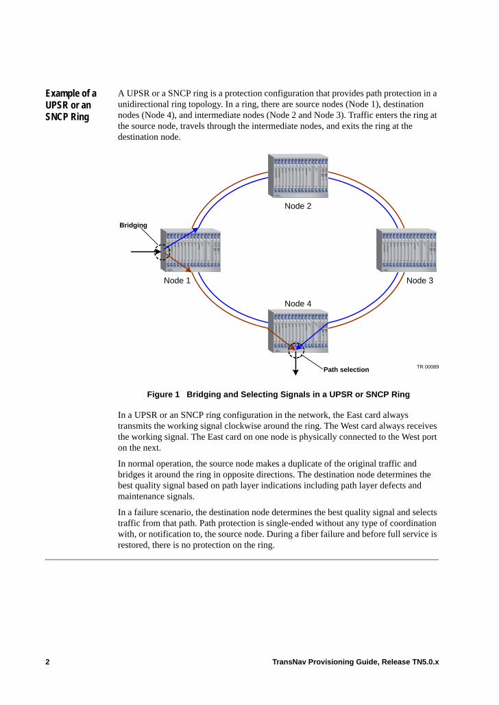
Example of a UPSR or an SNCP Ring
A UPSR or a SNCP ring is a protection configuration that provides path protection in a unidirectional ring topology. In a ring, there are source nodes (Node 1), destination nodes (Node 4), and intermediate nodes (Node 2 and Node 3). Traffic enters the ring at the source node, travels through the intermediate nodes, and exits the ring at the destination node.
Figure 1 Bridging and Selecting Signals in a UPSR or SNCP Ring
In a UPSR or an SNCP ring configuration in the network, the East card always transmits the working signal clockwise around the ring. The West card always receives the working signal. The East card on one node is physically connected to the West port on the next.
In normal operation, the source node makes a duplicate of the original traffic and bridges it around the ring in opposite directions. The destination node determines the best quality signal based on path layer indications including path layer defects and maintenance signals.
In a failure scenario, the destination node determines the best quality signal and selects traffic from that path. Path protection is single-ended without any type of coordination with, or notification to, the source node. During a fiber failure and before full service is restored, there is no protection on the ring.
Bridging
Node 1
Node 4
Path selection
Node 2
Node 3
TR 00089
2 TransNav Provisioning Guide, Release TN5.0.x
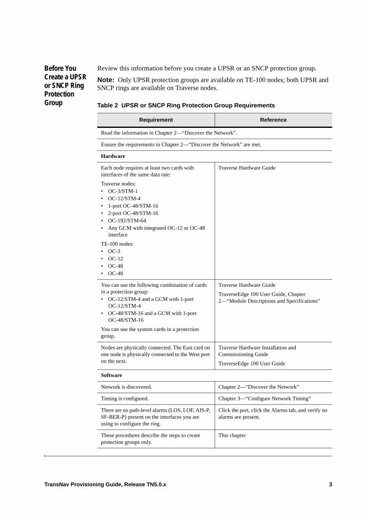
Before You Create a UPSR or SNCP Ring Protection Group
Review this information before you create a UPSR or an SNCP protection group.
Note: Only UPSR protection groups are available on TE-100 nodes; both UPSR and SNCP rings are available on Traverse nodes.
Table 2 UPSR or SNCP Ring Protection Group Requirements
Requirement Reference
Read the information in Chapter 2—“Discover the Network”.
Ensure the requirements in Chapter 2—“Discover the Network” are met.
Hardware
Each node requires at least two cards with interfaces of the same data rate:
Traverse nodes: • OC-3/STM-1• OC-12/STM-4• 1-port OC-48/STM-16• 2-port OC-48/STM-16• OC-192/STM-64• Any GCM with integrated OC-12 or OC-48
interface
TE-100 nodes: • OC-3• OC-12• OC-48• OC-48
Traverse Hardware Guide
You can use the following combination of cards in a protection group:• OC-12/STM-4 and a GCM with 1-port
OC-12/STM-4• OC-48/STM-16 and a GCM with 1-port
OC-48/STM-16
You can use the system cards in a protection group.
Traverse Hardware Guide
TraverseEdge 100 User Guide, Chapter 2—“Module Descriptions and Specifications”
Nodes are physically connected. The East card on one node is physically connected to the West port on the next.
Traverse Hardware Installation and Commissioning Guide
TraverseEdge 100 User Guide
Software
Network is discovered. Chapter 2—“Discover the Network”
Timing is configured. Chapter 3—“Configure Network Timing”
There are no path-level alarms (LOS, LOF, AIS-P, SF-BER-P) present on the interfaces you are using to configure the ring.
Click the port, click the Alarms tab, and verify no alarms are present.
These procedures describe the steps to create protection groups only.
This chapter
TransNav Provisioning Guide, Release TN5.0.x 3

Guidelines to Create a UPSR or SNCP Ring
Traverse Nodes. A single Traverse 2000 node supports the following number of UPSR or SNCP Ring protection groups:• Up to four on OC-192 or STM-64 rings• Up to nine on OC-48 or STM-16 rings
A single Traverse 1600 node supports the following number of UPSR or SNCP Ring protection groups:• Up to three on OC-192 or STM-64 rings• Up to seven on OC-48 or STM-16 rings
There can be up to 16 nodes in a UPSR or SNCP ring.
The East card on one node is physically connected to the West port on the next card.
In a UPSR or SNCP ring configuration, the East card always transmits the working signal clockwise around the ring. The West card always receives the working signal.
For end-to-end UPSR/SNCP protected services, the system automatically assigns the protected path, including the time slots. If you want to assign the protected path, provision a 1+1 path protected service instead.
TE-100 Nodes. A single TE-100 node supports two (2) SONET or STM optical interfaces and one (1) UPSR protection group or SNCP ring protection group.
A single TE-100 node is physically connected to two (2) other nodes. If the node is part of a protection ring, no other type of protection group can be added.
In a ring configuration, the East port is always Port 2 and transmits the working signal clockwise around the ring. The West port is always Port 1 and receives the working signal.
The East port on one node is physically connected to the West port on the next.
Important: For an SDH STM-16 node in an SNCP ring or linear TU-3/VC-3 configuration, at most 12 LO VC-3s are available:
– VC-4 channels 1–4 are unusable for any service, including pass-thru cross-connections, which is typical in TU-3 mode. LO VC-3 provisioning is available for VC-4 endpoints 5–8. VC-4 channels 9–16 can provide further provisioning for anything but LO-VC-3.
– SNCP rings greater than 4 nodes is impractical with LO VC-3 only (although you can provision other services on 5th and greater nodes)
4 TransNav Provisioning Guide, Release TN5.0.x
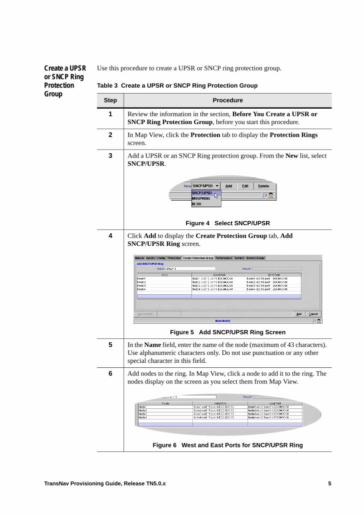
Create a UPSR or SNCP Ring Protection Group
Use this procedure to create a UPSR or SNCP ring protection group.
Table 3 Create a UPSR or SNCP Ring Protection Group
Step Procedure
1 Review the information in the section, Before You Create a UPSR or SNCP Ring Protection Group, before you start this procedure.
2 In Map View, click the Protection tab to display the Protection Rings screen.
3 Add a UPSR or an SNCP Ring protection group. From the New list, select SNCP/UPSR.
Figure 4 Select SNCP/UPSR
4 Click Add to display the Create Protection Group tab, Add SNCP/UPSR Ring screen.
Figure 5 Add SNCP/UPSR Ring Screen
5 In the Name field, enter the name of the node (maximum of 43 characters). Use alphanumeric characters only. Do not use punctuation or any other special character in this field.
6 Add nodes to the ring. In Map View, click a node to add it to the ring. The nodes display on the screen as you select them from Map View.
Figure 6 West and East Ports for SNCP/UPSR Ring
TransNav Provisioning Guide, Release TN5.0.x 5
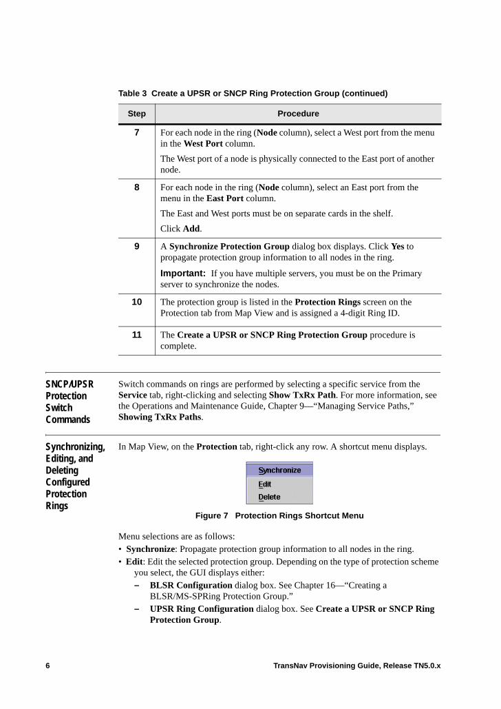
SNCP/UPSR Protection Switch Commands
Switch commands on rings are performed by selecting a specific service from the Service tab, right-clicking and selecting Show TxRx Path. For more information, see the Operations and Maintenance Guide, Chapter 9—“Managing Service Paths,” Showing TxRx Paths.
Synchronizing, Editing, and Deleting Configured Protection Rings
In Map View, on the Protection tab, right-click any row. A shortcut menu displays.
Figure 7 Protection Rings Shortcut Menu
Menu selections are as follows:• Synchronize: Propagate protection group information to all nodes in the ring.• Edit: Edit the selected protection group. Depending on the type of protection scheme
you select, the GUI displays either:– BLSR Configuration dialog box. See Chapter 16—“Creating a
BLSR/MS-SPRing Protection Group.”– UPSR Ring Configuration dialog box. See Create a UPSR or SNCP Ring
Protection Group.
7 For each node in the ring (Node column), select a West port from the menu in the West Port column.
The West port of a node is physically connected to the East port of another node.
8 For each node in the ring (Node column), select an East port from the menu in the East Port column.
The East and West ports must be on separate cards in the shelf.
Click Add.
9 A Synchronize Protection Group dialog box displays. Click Yes to propagate protection group information to all nodes in the ring.
Important: If you have multiple servers, you must be on the Primary server to synchronize the nodes.
10 The protection group is listed in the Protection Rings screen on the Protection tab from Map View and is assigned a 4-digit Ring ID.
11 The Create a UPSR or SNCP Ring Protection Group procedure is complete.
Table 3 Create a UPSR or SNCP Ring Protection Group (continued)
Step Procedure
6 TransNav Provisioning Guide, Release TN5.0.x
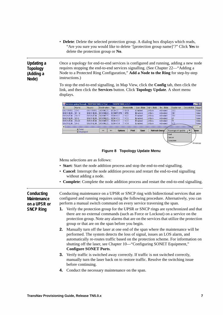
• Delete: Delete the selected protection group. A dialog box displays which reads, “Are you sure you would like to delete ‘[protection group name]’?” Click Yes to delete the protection group or No.
Updating a Topology (Adding a Node)
Once a topology for end-to-end services is configured and running, adding a new node requires stopping the end-to-end services signalling. (See Chapter 22—“Adding a Node to a Protected Ring Configuration,” Add a Node to the Ring for step-by-step instructions.)
To stop the end-to-end signalling, in Map View, click the Config tab, then click the link, and then click the Services button. Click Topology Update. A short menu displays.
Figure 8 Topology Update Menu
Menu selections are as follows:• Start: Start the node addition process and stop the end-to-end signalling. • Cancel: Interrupt the node addition process and restart the end-to-end signalling
without adding a node.• Complete: Complete the node addition process and restart the end-to-end signalling.
Conducting Maintenance on a UPSR or SNCP Ring
Conducting maintenance on a UPSR or SNCP ring with bidirectional services that are configured and running requires using the following procedure. Alternatively, you can perform a manual switch command on every service traversing the span.
1. Verify the protection group for the UPSR or SNCP rings are synchronized and that there are no external commands (such as Force or Lockout) on a service on the protection group. Note any alarms that are on the services that utilize the protection group or that are on the span before you begin.
2. Manually turn off the laser at one end of the span where the maintenance will be performed. The system detects the loss of signal, issues an LOS alarm, and automatically re-routes traffic based on the protection scheme. For information on shutting off the laser, see Chapter 10—“Configuring SONET Equipment,” Configure SONET Ports.
3. Verify traffic is switched away correctly. If traffic is not switched correctly, manually turn the laser back on to restore traffic. Resolve the switching issue before continuing.
4. Conduct the necessary maintenance on the span.
TransNav Provisioning Guide, Release TN5.0.x 7

5. After the maintenance is complete, manually turn the laser back on that was turned off earlier. The system detects the change in signal and the LOS alarm is cleared.
6. Verify there are no new alarms on the services for the protection group or that are on the span.
8 TransNav Provisioning Guide, Release TN5.0.x
Chapter 18 Creating Equipment Protection Groups
Introduction Use equipment protection switching to create redundancy for the electrical interface cards, the VT/TU 5G Switch card, or for the VTX/VCX hardware on the cards with the integrated switching component.
Ensure that no services are activated on either the working or protecting card before creating an equipment protection group.
This chapter provides configuration procedures for network link (trunk) and tributary protection groups in a Traverse network.• Before You Configure Equipment Protection• Guidelines to Create an Equipment Protection Group• Create an Equipment Protection Group
This chapter also includes information on commands that are available for equipment protection and requesting priorities for equipment protection. • Equipment Protection Switch Commands• Protecting Card Switch Commands• Working Card Switch Commands• Request Priorities for Equipment Protection
Only the Traverse system supports configurable equipment protection switching.
For an explanation of how the TE-100 supports equipment protection switching, see the TraverseEdge 100 User Guide, Chapter 1—“TE-100 Platform Description and Specifications.”
Before You Configure Equipment Protection
Review this information before you create an equipment protection group.
Table 1 Equipment Protection Requirements
Requirement Reference
Read the information in Chapter 1—“TN5.0.x Provisioning Overview.”
Ensure the requirements in Chapter 2—“Discover the Network,” Before You Start Provisioning Your Network are met.
TransNav Provisioning Guide, Release TN5.0.x 1
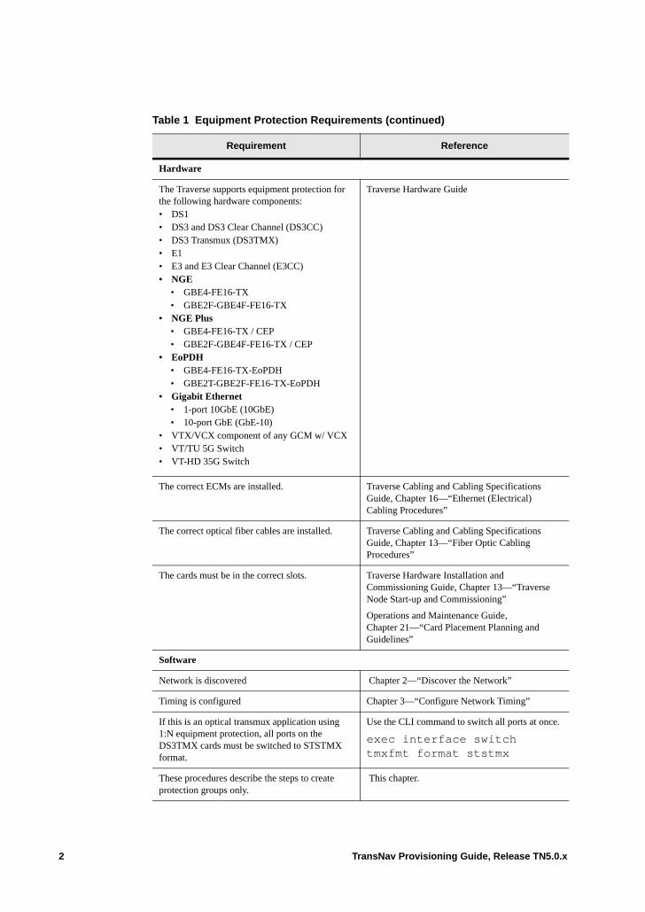
Hardware
The Traverse supports equipment protection for the following hardware components:• DS1• DS3 and DS3 Clear Channel (DS3CC)• DS3 Transmux (DS3TMX)• E1• E3 and E3 Clear Channel (E3CC)• NGE
• GBE4-FE16-TX• GBE2F-GBE4F-FE16-TX
• NGE Plus• GBE4-FE16-TX / CEP• GBE2F-GBE4F-FE16-TX / CEP
• EoPDH• GBE4-FE16-TX-EoPDH• GBE2T-GBE2F-FE16-TX-EoPDH
• Gigabit Ethernet• 1-port 10GbE (10GbE)• 10-port GbE (GbE-10)
• VTX/VCX component of any GCM w/ VCX• VT/TU 5G Switch• VT-HD 35G Switch
Traverse Hardware Guide
The correct ECMs are installed. Traverse Cabling and Cabling Specifications Guide, Chapter 16—“Ethernet (Electrical) Cabling Procedures”
The correct optical fiber cables are installed. Traverse Cabling and Cabling Specifications Guide, Chapter 13—“Fiber Optic Cabling Procedures”
The cards must be in the correct slots. Traverse Hardware Installation and Commissioning Guide, Chapter 13—“Traverse Node Start-up and Commissioning”
Operations and Maintenance Guide, Chapter 21—“Card Placement Planning and Guidelines”
Software
Network is discovered Chapter 2—“Discover the Network”
Timing is configured Chapter 3—“Configure Network Timing”
If this is an optical transmux application using 1:N equipment protection, all ports on the DS3TMX cards must be switched to STSTMX format.
Use the CLI command to switch all ports at once.
exec interface switch tmxfmt format ststmx
These procedures describe the steps to create protection groups only.
This chapter.
Table 1 Equipment Protection Requirements (continued)
Requirement Reference
2 TransNav Provisioning Guide, Release TN5.0.x
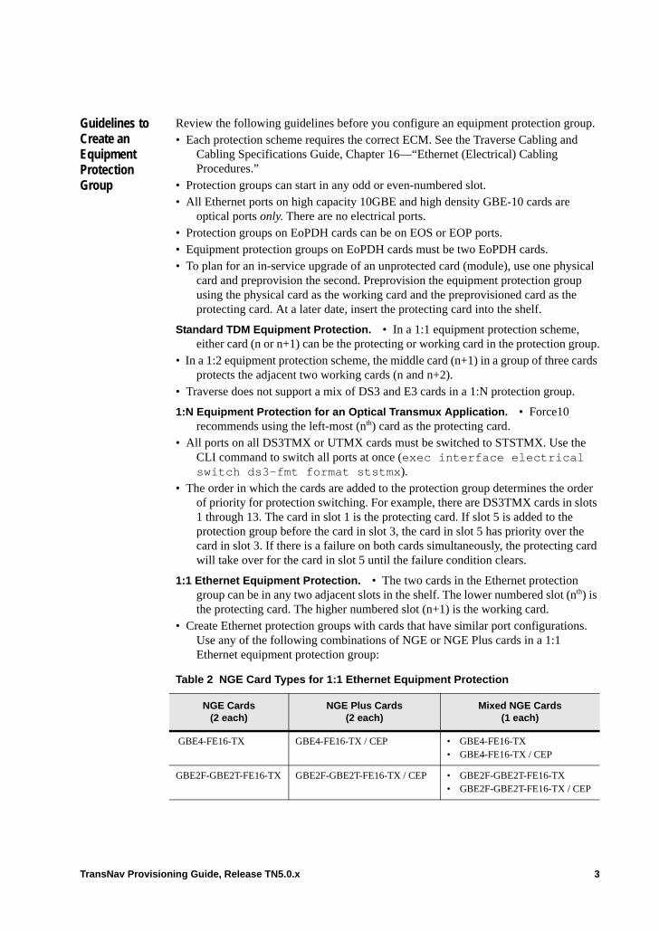
Guidelines to Create an Equipment Protection Group
Review the following guidelines before you configure an equipment protection group.• Each protection scheme requires the correct ECM. See the Traverse Cabling and
Cabling Specifications Guide, Chapter 16—“Ethernet (Electrical) Cabling Procedures.”
• Protection groups can start in any odd or even-numbered slot.• All Ethernet ports on high capacity 10GBE and high density GBE-10 cards are
optical ports only. There are no electrical ports.• Protection groups on EoPDH cards can be on EOS or EOP ports.• Equipment protection groups on EoPDH cards must be two EoPDH cards. • To plan for an in-service upgrade of an unprotected card (module), use one physical
card and preprovision the second. Preprovision the equipment protection group using the physical card as the working card and the preprovisioned card as the protecting card. At a later date, insert the protecting card into the shelf.
Standard TDM Equipment Protection. • In a 1:1 equipment protection scheme, either card (n or n+1) can be the protecting or working card in the protection group.
• In a 1:2 equipment protection scheme, the middle card (n+1) in a group of three cards protects the adjacent two working cards (n and n+2).
• Traverse does not support a mix of DS3 and E3 cards in a 1:N protection group.
1:N Equipment Protection for an Optical Transmux Application. • Force10 recommends using the left-most (nth) card as the protecting card.
• All ports on all DS3TMX or UTMX cards must be switched to STSTMX. Use the CLI command to switch all ports at once (exec interface electrical switch ds3-fmt format ststmx).
• The order in which the cards are added to the protection group determines the order of priority for protection switching. For example, there are DS3TMX cards in slots 1 through 13. The card in slot 1 is the protecting card. If slot 5 is added to the protection group before the card in slot 3, the card in slot 5 has priority over the card in slot 3. If there is a failure on both cards simultaneously, the protecting card will take over for the card in slot 5 until the failure condition clears.
1:1 Ethernet Equipment Protection. • The two cards in the Ethernet protection group can be in any two adjacent slots in the shelf. The lower numbered slot (nth) is the protecting card. The higher numbered slot (n+1) is the working card.
• Create Ethernet protection groups with cards that have similar port configurations. Use any of the following combinations of NGE or NGE Plus cards in a 1:1 Ethernet equipment protection group:
Table 2 NGE Card Types for 1:1 Ethernet Equipment Protection
NGE Cards (2 each)
NGE Plus Cards(2 each)
Mixed NGE Cards(1 each)
GBE4-FE16-TX GBE4-FE16-TX / CEP • GBE4-FE16-TX• GBE4-FE16-TX / CEP
GBE2F-GBE2T-FE16-TX GBE2F-GBE2T-FE16-TX / CEP • GBE2F-GBE2T-FE16-TX• GBE2F-GBE2T-FE16-TX / CEP
TransNav Provisioning Guide, Release TN5.0.x 3
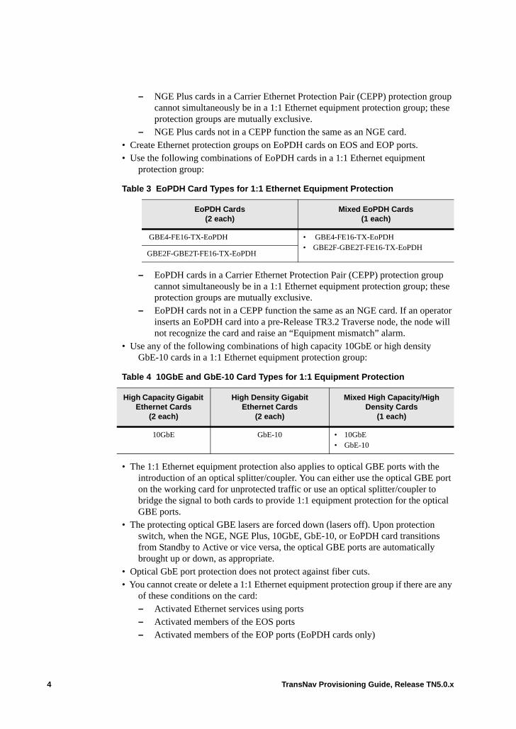
– NGE Plus cards in a Carrier Ethernet Protection Pair (CEPP) protection group cannot simultaneously be in a 1:1 Ethernet equipment protection group; these protection groups are mutually exclusive.
– NGE Plus cards not in a CEPP function the same as an NGE card. • Create Ethernet protection groups on EoPDH cards on EOS and EOP ports. • Use the following combinations of EoPDH cards in a 1:1 Ethernet equipment
protection group:
– EoPDH cards in a Carrier Ethernet Protection Pair (CEPP) protection group cannot simultaneously be in a 1:1 Ethernet equipment protection group; these protection groups are mutually exclusive.
– EoPDH cards not in a CEPP function the same as an NGE card. If an operator inserts an EoPDH card into a pre-Release TR3.2 Traverse node, the node will not recognize the card and raise an “Equipment mismatch” alarm.
• Use any of the following combinations of high capacity 10GbE or high density GbE-10 cards in a 1:1 Ethernet equipment protection group:
• The 1:1 Ethernet equipment protection also applies to optical GBE ports with the introduction of an optical splitter/coupler. You can either use the optical GBE port on the working card for unprotected traffic or use an optical splitter/coupler to bridge the signal to both cards to provide 1:1 equipment protection for the optical GBE ports.
• The protecting optical GBE lasers are forced down (lasers off). Upon protection switch, when the NGE, NGE Plus, 10GbE, GbE-10, or EoPDH card transitions from Standby to Active or vice versa, the optical GBE ports are automatically brought up or down, as appropriate.
• Optical GbE port protection does not protect against fiber cuts.• You cannot create or delete a 1:1 Ethernet equipment protection group if there are any
of these conditions on the card:– Activated Ethernet services using ports– Activated members of the EOS ports– Activated members of the EOP ports (EoPDH cards only)
Table 3 EoPDH Card Types for 1:1 Ethernet Equipment Protection
EoPDH Cards (2 each)
Mixed EoPDH Cards(1 each)
GBE4-FE16-TX-EoPDH • GBE4-FE16-TX-EoPDH • GBE2F-GBE2T-FE16-TX-EoPDH
GBE2F-GBE2T-FE16-TX-EoPDH
Table 4 10GbE and GbE-10 Card Types for 1:1 Equipment Protection
High Capacity Gigabit Ethernet Cards
(2 each)
High Density Gigabit Ethernet Cards
(2 each)
Mixed High Capacity/High Density Cards
(1 each)
10GbE GbE-10 • 10GbE• GbE-10
4 TransNav Provisioning Guide, Release TN5.0.x
– EOS ports, EOP ports, LAGs, or Policers are configured– Ethernet facilities are currently in facility or terminal loopbacks
• 1:1 Ethernet electrical equipment protection:– interworks with all other supported optical (line and path) protection schemes.– does not interwork with 1+1 EOS or EOP port protection.
EOS and EOP port alarms will be raised on the Active card in a 1:1 Protection Group.
For information on the effect of NGE, NGE Plus and EoPDH card transitions on PM counts, see the Operations and Maintenance Guide, Chapter 7—“Ethernet Performance Parameters.”
TransNav Provisioning Guide, Release TN5.0.x 5
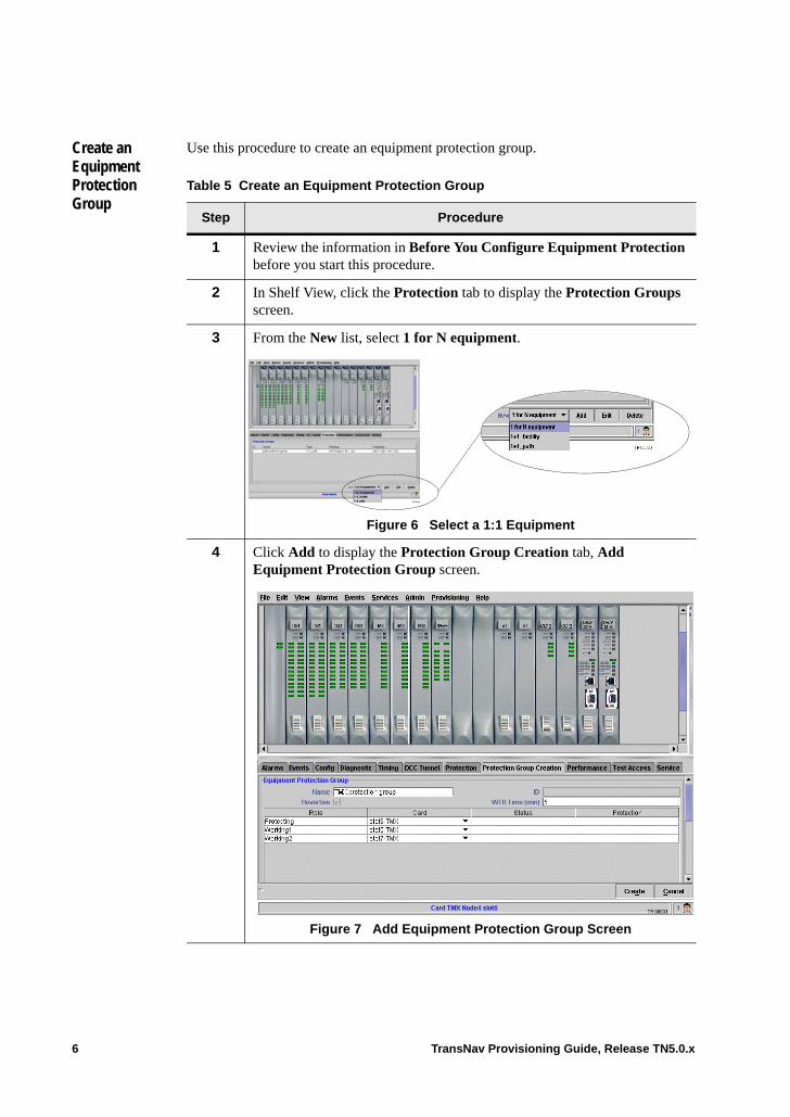
Create an Equipment Protection Group
Use this procedure to create an equipment protection group.
Table 5 Create an Equipment Protection Group
Step Procedure
1 Review the information in Before You Configure Equipment Protection before you start this procedure.
2 In Shelf View, click the Protection tab to display the Protection Groups screen.
3 From the New list, select 1 for N equipment.
Figure 6 Select a 1:1 Equipment
4 Click Add to display the Protection Group Creation tab, Add Equipment Protection Group screen.
Figure 7 Add Equipment Protection Group Screen
6 TransNav Provisioning Guide, Release TN5.0.x
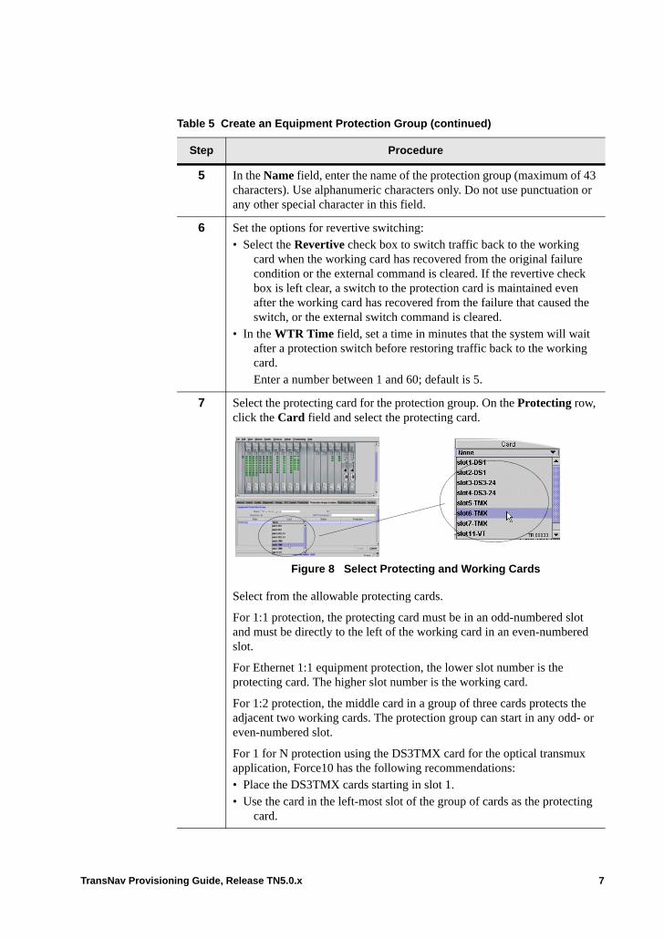
5 In the Name field, enter the name of the protection group (maximum of 43 characters). Use alphanumeric characters only. Do not use punctuation or any other special character in this field.
6 Set the options for revertive switching:• Select the Revertive check box to switch traffic back to the working
card when the working card has recovered from the original failure condition or the external command is cleared. If the revertive check box is left clear, a switch to the protection card is maintained even after the working card has recovered from the failure that caused the switch, or the external switch command is cleared.
• In the WTR Time field, set a time in minutes that the system will wait after a protection switch before restoring traffic back to the working card.Enter a number between 1 and 60; default is 5.
7 Select the protecting card for the protection group. On the Protecting row, click the Card field and select the protecting card.
Figure 8 Select Protecting and Working Cards
Select from the allowable protecting cards.
For 1:1 protection, the protecting card must be in an odd-numbered slot and must be directly to the left of the working card in an even-numbered slot.
For Ethernet 1:1 equipment protection, the lower slot number is the protecting card. The higher slot number is the working card.
For 1:2 protection, the middle card in a group of three cards protects the adjacent two working cards. The protection group can start in any odd- or even-numbered slot.
For 1 for N protection using the DS3TMX card for the optical transmux application, Force10 has the following recommendations: • Place the DS3TMX cards starting in slot 1.• Use the card in the left-most slot of the group of cards as the protecting
card.
Table 5 Create an Equipment Protection Group (continued)
Step Procedure
TransNav Provisioning Guide, Release TN5.0.x 7

8 Select the working cards for the protection group. On each Working row, click the Card field and select the working card. Select from the allowable working cards.
For 1:2 and 1 for N protection, the order in which you add cards to this list is the order of protection priority. Specifically, the card that you select for Working 1 has priority over the card you select for Working 12.
9 Click Create to create the protection group and return to the Protection Groups screen on the Protection tab.
Figure 9 Protection Groups Screen
The system assigns an identification number to the new protection group and displays it in the ID column.
10 The Create an Equipment Protection Group procedure is complete.
Table 5 Create an Equipment Protection Group (continued)
Step Procedure
8 TransNav Provisioning Guide, Release TN5.0.x

Equipment Protection Switch Commands
You can edit the equipment protection group from the Protection tab in two ways:• Highlight the protection group and right-click; select Edit.• Double-click the protection group.
The Equipment Protection Group screen displays.
Figure 0-10 Equipment Protection Group Configuration Screen
The switch commands differ between the protecting and working cards as described below.
Protecting Card Switch Commands. Right-click the protecting card to display the switch commands. See Request Priorities for Equipment Protection for switch command hierarchy.• Clear: Clears all switch commands from the card. • Lockout: Prevents protecting card from becoming active for any of the working
cards.• Forced: Forces all traffic from protecting card unless a request of equal or higher
priority is in effect. • Manual: Manually switch traffic from the protecting card to the working card unless
a request of equal or higher priority is in effect.
Working Card Switch Commands . Right-click the working card to display the switch commands. For switching request priorities, see Request Priorities for Equipment Protection.• Clear: Clears all switch commands from the card.• Lockout: Prevents traffic on this working card from switching to the protecting card. • Forced: Forces traffic from working card to protecting card unless a request of equal
or higher priority is in effect. • Manual: Manually switch traffic from working card to protecting card unless a
request of equal or higher priority is in effect.
For Equipment Protection, the switch command priorities are as follows:
Request Priorities for Equipment Protection. Protection switching request priorities (from highest to lowest) for equipment protection are:• Clear: User-initiated action
TransNav Provisioning Guide, Release TN5.0.x 9

• Lockout: User-initiated action. A lockout of working and protecting can coexist• Forced switch: User-initiated protection switch• Card Failure (automatic)• Manual switch: User-initiated protection switch• Wait to Restore
10 TransNav Provisioning Guide, Release TN5.0.x
Chapter 19 Carrier Ethernet Protection
Introduction Use a Carrier Ethernet Protection Pair (CEPP) with NGE Plus or EoPDH cards to create inter-card link aggregation groups and aggregate data from Ethernet ports on two cards to a single EOS link. CEPP can also be used on EOS or EOP links on two EoPDH cards.
Similar to other Traverse equipment protection groups, each CEPP has two cards that are designated as the Working and Protecting cards. In each group, the cards alternate the active and standby roles, with only the active cards sending and receiving data on the backplane.
Unlike other equipment protection groups, a CEPP effectively doubles the number of physical Ethernet ports of a single NGE Plus or EoPDH card. All line-side ports on both cards connect to the CEPP and carry independent traffic. When both cards are up, CEPP behaves like a single card with 40 physical Ethernet and 64 EOS ports on NGE cards. For EoPDH cards, a maximum of 128 ports are available. The ports can be either EOS, EOP, or a combination of EOS and EOP ports that total 128 ports. EOP ports are available on EoPDH cards only.
This chapter provides configuration procedures for Carrier Ethernet Protection Pair (CEPP) protection groups in a Traverse network:• Before You Configure CEPP• Guidelines to Create a CEPP Protection Group• Inter-card Link Aggregation Groups
Before You Configure CEPP
Review this information before you create a CEPP protection group.
Table 1 Equipment Protection Requirements
Requirement Reference
Read the information in Chapter 1—“TN5.0.x Provisioning Overview.”
Ensure the requirements in Chapter 2—“Discover the Network,” Before You Start Provisioning Your Network are met.
TransNav Provisioning Guide, Release TN5.0.x 1
Guidelines to Create a CEPP Protection Group
Review the following guidelines before you configure a CEPP protection group.• Each protection scheme requires the correct ECM. See the Traverse Cabling and
Cabling Specifications Guide, Chapter 16—“Ethernet (Electrical) Cabling Procedures.”
• Create Ethernet protection groups with cards that have similar port configurations on the same card type (either NGE Plus or EoPDH). Use either of the following combinations of NGE Plus cards:– two GBE4-FE16-TX / CEP cards– two GBE2T-GBE2F-FE16-TX / CEP cards Or combinations of the following EoPDH cards: – two GBE4-FE16-TX-EoPDH– two GBE2T-GBE2F-FE16-TX-EoPDH
• Protection groups can start in any odd or even-numbered slot.• Force10 recommends adjacent card configuration, although the cards can be
non-adjacent. (Non-adjacent cards require two ECMs.)• NGE Plus or EoPDH cards in a CEPP protection group cannot simultaneously be in a
1:N equipment protection group; these protection groups are mutually exclusive. NGE Plus or EoPDH cards that are not in a CEPP function the same as an NGE card.
• NGE Plus or EoPDH cards in a Carrier Ethernet Protection Pair (CEPP) protection group cannot simultaneously be in a 1:1 Ethernet equipment protection group; these protection groups are mutually exclusive.
Hardware
The Traverse supports CEPP protection for the following NGE Plus and EoPDH hardware components:
Traverse Hardware Guide
Verify the correct ECMs are installed. Traverse Cabling and Cabling Specifications Guide
Ensure the cards are in the correct slots. Traverse Hardware Installation and Commissioning Guide. Chapter 13—“Traverse Node Start-up and Commissioning”
Operations and Maintenance Guide, Chapter 21—“Card Placement Planning and Guidelines”
Software
Verify the network is discovered. Chapter 2—“Discover the Network”
Ensure the timing is configured. Chapter 3—“Configure Network Timing”
These procedures describe the steps to create protection groups only.
This chapter.
Table 1 Equipment Protection Requirements (continued)
Requirement Reference
2 TransNav Provisioning Guide, Release TN5.0.x

• NGE Plus or EoPDH cards not in a CEPP function the same as an NGE card. However, if an operator inserts an NGE Plus or EoPDH card into a Traverse node with incompatible software, the node will not recognize the card and will raise an “Equipment mismatch” alarm.
• The 1:1 Ethernet equipment protection also applies to optical GBE ports due to an optical splitter/coupler. You can either use the optical GBE port on the working card for unprotected traffic or use an optical splitter/coupler to bridge the signal to both cards to provide 1:1 equipment protection for the optical GBE ports.
• The protecting optical GBE lasers are forced down (lasers off). Upon protection switch, when the NGE, NGE Plus, or EoPDH card transitions from Standby to Active or vice versa, the optical GBE ports are automatically brought up or down, as appropriate.
• Optical GBE port protection does not protect against fiber cuts.• You cannot create or delete a CEPP protection group if there are any of these
conditions on the working or protect card:– Activated Ethernet services using ports– Activated members of the EOS or EOP ports– Any services are activated on either the working or protecting card– EOS ports, EOP ports, VRBs, LAGs, or Policers are configured– Ethernet facilities are currently in facility or terminal loopbacks
• CEPP protection groups:– interwork with all other supported optical (line and path) protection schemes– do not interwork with 1+1 EOS port protection
For information on the effect of NGE, NGE Plus and EoPDH card transitions on PM counts, see the Operations and Maintenance Guide, Chapter 7—“Ethernet Performance Parameters.”
TransNav Provisioning Guide, Release TN5.0.x 3
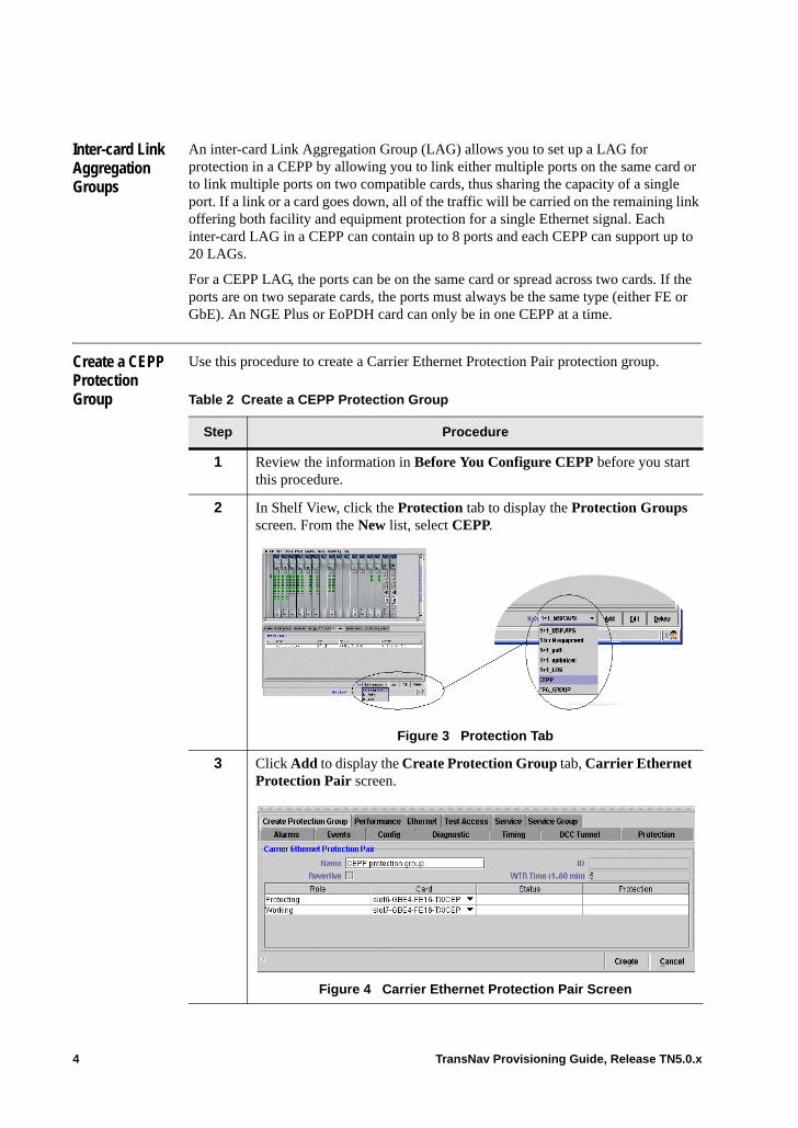
Inter-card Link Aggregation Groups
An inter-card Link Aggregation Group (LAG) allows you to set up a LAG for protection in a CEPP by allowing you to link either multiple ports on the same card or to link multiple ports on two compatible cards, thus sharing the capacity of a single port. If a link or a card goes down, all of the traffic will be carried on the remaining link offering both facility and equipment protection for a single Ethernet signal. Each inter-card LAG in a CEPP can contain up to 8 ports and each CEPP can support up to 20 LAGs.
For a CEPP LAG, the ports can be on the same card or spread across two cards. If the ports are on two separate cards, the ports must always be the same type (either FE or GbE). An NGE Plus or EoPDH card can only be in one CEPP at a time.
Create a CEPP Protection Group
Use this procedure to create a Carrier Ethernet Protection Pair protection group.
Table 2 Create a CEPP Protection Group
Step Procedure
1 Review the information in Before You Configure CEPP before you start this procedure.
2 In Shelf View, click the Protection tab to display the Protection Groups screen. From the New list, select CEPP.
Figure 3 Protection Tab
3 Click Add to display the Create Protection Group tab, Carrier Ethernet Protection Pair screen.
.
Figure 4 Carrier Ethernet Protection Pair Screen
4 TransNav Provisioning Guide, Release TN5.0.x
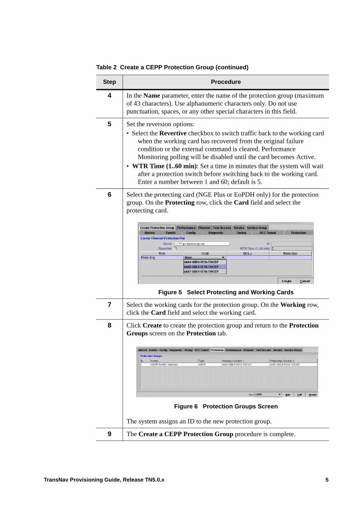
4 In the Name parameter, enter the name of the protection group (maximum of 43 characters). Use alphanumeric characters only. Do not use punctuation, spaces, or any other special characters in this field.
5 Set the reversion options:• Select the Revertive checkbox to switch traffic back to the working card
when the working card has recovered from the original failure condition or the external command is cleared. Performance Monitoring polling will be disabled until the card becomes Active.
• WTR Time (1..60 min): Set a time in minutes that the system will wait after a protection switch before switching back to the working card. Enter a number between 1 and 60; default is 5.
6 Select the protecting card (NGE Plus or EoPDH only) for the protection group. On the Protecting row, click the Card field and select the protecting card.
Figure 5 Select Protecting and Working Cards
7 Select the working cards for the protection group. On the Working row, click the Card field and select the working card.
8 Click Create to create the protection group and return to the Protection Groups screen on the Protection tab.
Figure 6 Protection Groups Screen
The system assigns an ID to the new protection group.
9 The Create a CEPP Protection Group procedure is complete.
Table 2 Create a CEPP Protection Group (continued)
Step Procedure
TransNav Provisioning Guide, Release TN5.0.x 5

6 TransNav Provisioning Guide, Release TN5.0.x
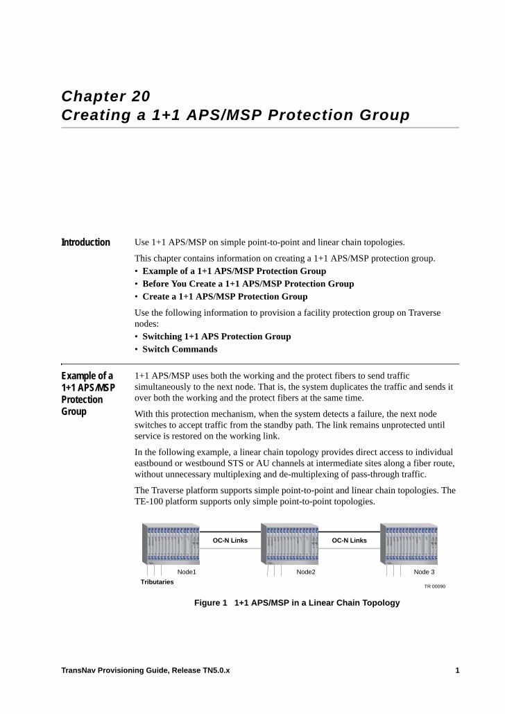
Chapter 20 Creating a 1+1 APS/MSP Protection Group
Introduction Use 1+1 APS/MSP on simple point-to-point and linear chain topologies.
This chapter contains information on creating a 1+1 APS/MSP protection group.• Example of a 1+1 APS/MSP Protection Group• Before You Create a 1+1 APS/MSP Protection Group• Create a 1+1 APS/MSP Protection Group
Use the following information to provision a facility protection group on Traverse nodes: • Switching 1+1 APS Protection Group• Switch Commands
Example of a 1+1 APS/MSP Protection Group
1+1 APS/MSP uses both the working and the protect fibers to send traffic simultaneously to the next node. That is, the system duplicates the traffic and sends it over both the working and the protect fibers at the same time.
With this protection mechanism, when the system detects a failure, the next node switches to accept traffic from the standby path. The link remains unprotected until service is restored on the working link.
In the following example, a linear chain topology provides direct access to individual eastbound or westbound STS or AU channels at intermediate sites along a fiber route, without unnecessary multiplexing and de-multiplexing of pass-through traffic.
The Traverse platform supports simple point-to-point and linear chain topologies. The TE-100 platform supports only simple point-to-point topologies.
Figure 1 1+1 APS/MSP in a Linear Chain Topology
OC-N Links
Node1
Tributaries
OC-N Links
Node2 Node 3
TR 00090
TransNav Provisioning Guide, Release TN5.0.x 1

Configure 1+1 APS/MSP protection at for each facility connected to the next Traverse node. In this example, configure one 1+1 APS/MSP protection group at Node 1 and Node 3. Configure two protection groups at Node 2.
2 TransNav Provisioning Guide, Release TN5.0.x
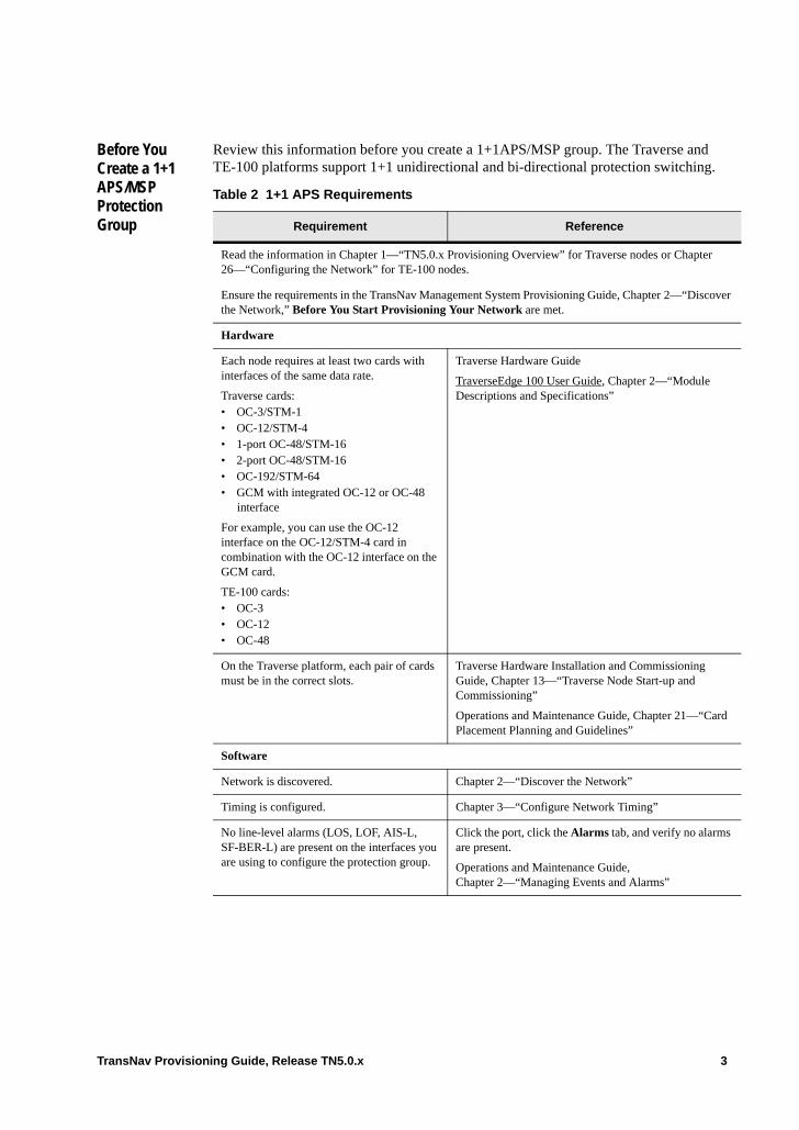
Before You Create a 1+1 APS/MSP Protection Group
Review this information before you create a 1+1APS/MSP group. The Traverse and TE-100 platforms support 1+1 unidirectional and bi-directional protection switching.
Table 2 1+1 APS Requirements
Requirement Reference
Read the information in Chapter 1—“TN5.0.x Provisioning Overview” for Traverse nodes or Chapter 26—“Configuring the Network” for TE-100 nodes.
Ensure the requirements in the TransNav Management System Provisioning Guide, Chapter 2—“Discover the Network,” Before You Start Provisioning Your Network are met.
Hardware
Each node requires at least two cards with interfaces of the same data rate.
Traverse cards: • OC-3/STM-1• OC-12/STM-4• 1-port OC-48/STM-16• 2-port OC-48/STM-16• OC-192/STM-64• GCM with integrated OC-12 or OC-48
interface
For example, you can use the OC-12 interface on the OC-12/STM-4 card in combination with the OC-12 interface on the GCM card.
TE-100 cards:• OC-3• OC-12• OC-48
Traverse Hardware Guide
TraverseEdge 100 User Guide, Chapter 2—“Module Descriptions and Specifications”
On the Traverse platform, each pair of cards must be in the correct slots.
Traverse Hardware Installation and Commissioning Guide, Chapter 13—“Traverse Node Start-up and Commissioning”
Operations and Maintenance Guide, Chapter 21—“Card Placement Planning and Guidelines”
Software
Network is discovered. Chapter 2—“Discover the Network”
Timing is configured. Chapter 3—“Configure Network Timing”
No line-level alarms (LOS, LOF, AIS-L, SF-BER-L) are present on the interfaces you are using to configure the protection group.
Click the port, click the Alarms tab, and verify no alarms are present.
Operations and Maintenance Guide, Chapter 2—“Managing Events and Alarms”
TransNav Provisioning Guide, Release TN5.0.x 3
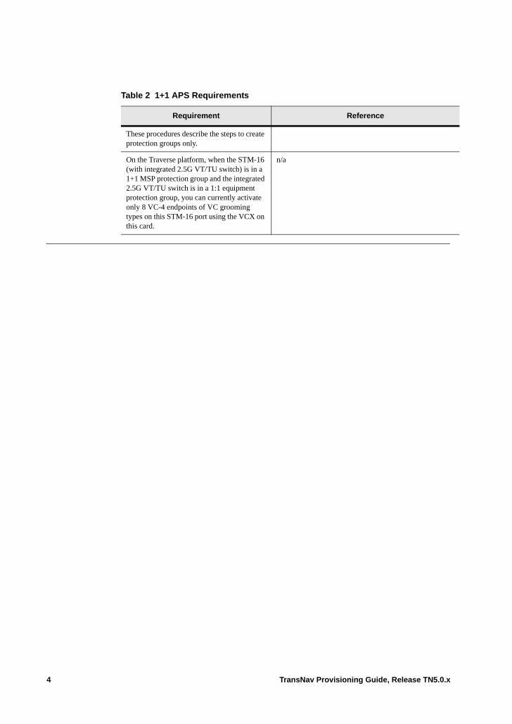
These procedures describe the steps to create protection groups only.
On the Traverse platform, when the STM-16 (with integrated 2.5G VT/TU switch) is in a 1+1 MSP protection group and the integrated 2.5G VT/TU switch is in a 1:1 equipment protection group, you can currently activate only 8 VC-4 endpoints of VC grooming types on this STM-16 port using the VCX on this card.
n/a
Table 2 1+1 APS Requirements
Requirement Reference
4 TransNav Provisioning Guide, Release TN5.0.x
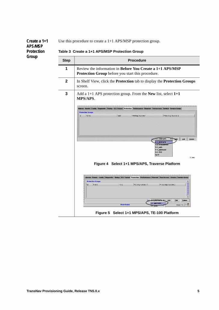
Create a 1+1 APS/MSP Protection Group
Use this procedure to create a 1+1 APS/MSP protection group.
Table 3 Create a 1+1 APS/MSP Protection Group
Step Procedure
1 Review the information in Before You Create a 1+1 APS/MSP Protection Group before you start this procedure.
2 In Shelf View, click the Protection tab to display the Protection Groups screen.
3 Add a 1+1 APS protection group. From the New list, select 1+1 MPS/APS.
Figure 4 Select 1+1 MPS/APS, Traverse Platform
Figure 5 Select 1+1 MPS/APS, TE-100 Platform
TransNav Provisioning Guide, Release TN5.0.x 5
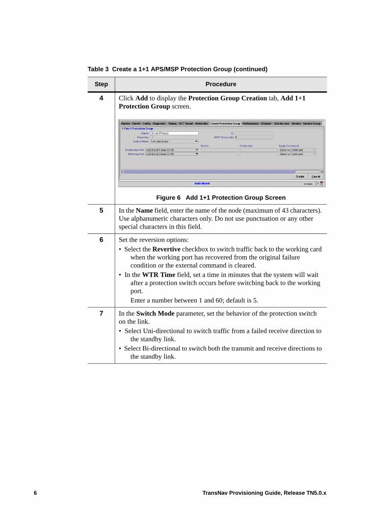
4 Click Add to display the Protection Group Creation tab, Add 1+1 Protection Group screen.
Figure 6 Add 1+1 Protection Group Screen
5 In the Name field, enter the name of the node (maximum of 43 characters). Use alphanumeric characters only. Do not use punctuation or any other special characters in this field.
6 Set the reversion options:• Select the Revertive checkbox to switch traffic back to the working card
when the working port has recovered from the original failure condition or the external command is cleared.
• In the WTR Time field, set a time in minutes that the system will wait after a protection switch occurs before switching back to the working port.Enter a number between 1 and 60; default is 5.
7 In the Switch Mode parameter, set the behavior of the protection switch on the link. • Select Uni-directional to switch traffic from a failed receive direction to
the standby link.• Select Bi-directional to switch both the transmit and receive directions to
the standby link.
Table 3 Create a 1+1 APS/MSP Protection Group (continued)
Step Procedure
6 TransNav Provisioning Guide, Release TN5.0.x
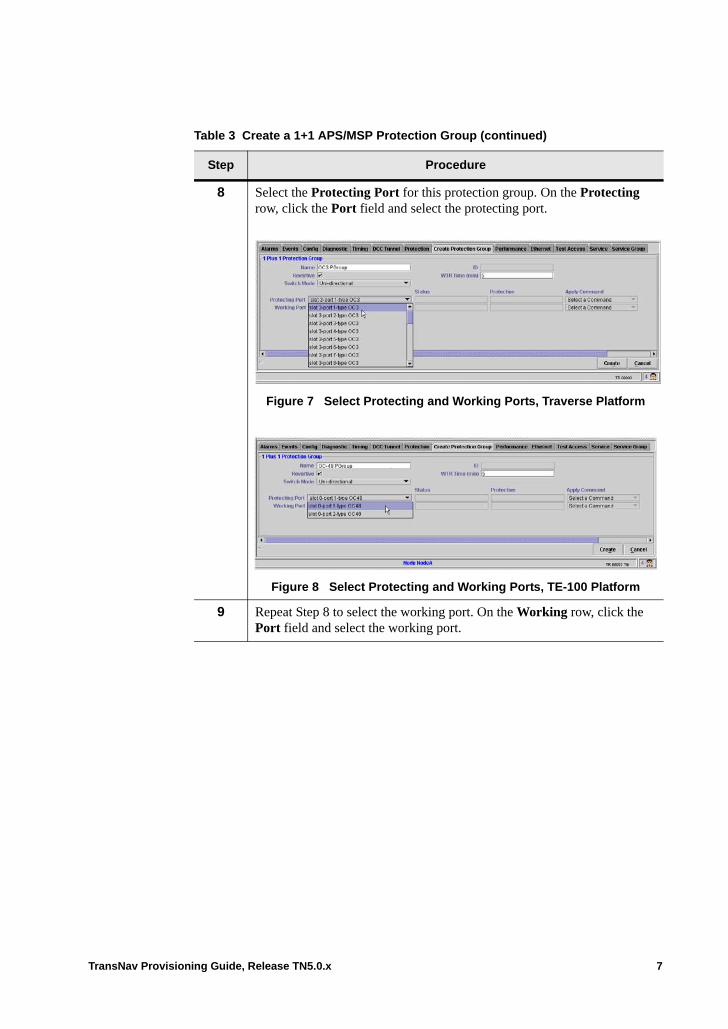
8 Select the Protecting Port for this protection group. On the Protecting row, click the Port field and select the protecting port.
Figure 7 Select Protecting and Working Ports, Traverse Platform
Figure 8 Select Protecting and Working Ports, TE-100 Platform
9 Repeat Step 8 to select the working port. On the Working row, click the Port field and select the working port.
Table 3 Create a 1+1 APS/MSP Protection Group (continued)
Step Procedure
TransNav Provisioning Guide, Release TN5.0.x 7
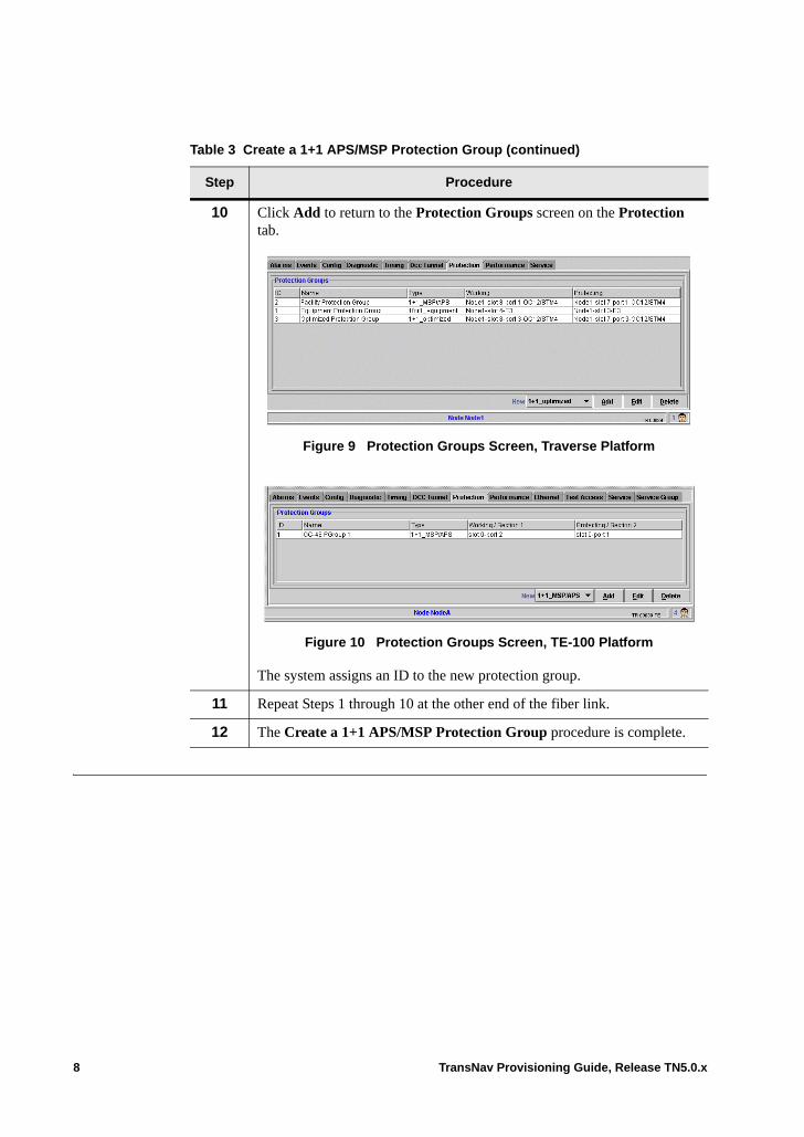
10 Click Add to return to the Protection Groups screen on the Protection tab.
Figure 9 Protection Groups Screen, Traverse Platform
Figure 10 Protection Groups Screen, TE-100 Platform
The system assigns an ID to the new protection group.
11 Repeat Steps 1 through 10 at the other end of the fiber link.
12 The Create a 1+1 APS/MSP Protection Group procedure is complete.
Table 3 Create a 1+1 APS/MSP Protection Group (continued)
Step Procedure
8 TransNav Provisioning Guide, Release TN5.0.x
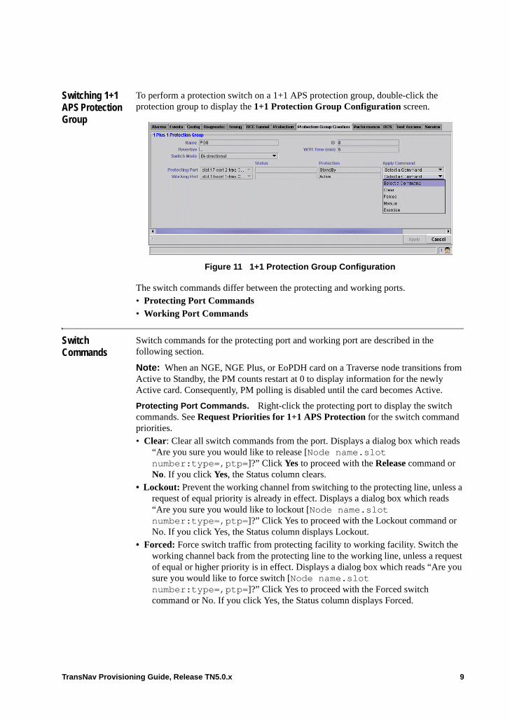
Switching 1+1 APS Protection Group
To perform a protection switch on a 1+1 APS protection group, double-click the protection group to display the 1+1 Protection Group Configuration screen.
Figure 11 1+1 Protection Group Configuration
The switch commands differ between the protecting and working ports. • Protecting Port Commands• Working Port Commands
Switch Commands
Switch commands for the protecting port and working port are described in the following section.
Note: When an NGE, NGE Plus, or EoPDH card on a Traverse node transitions from Active to Standby, the PM counts restart at 0 to display information for the newly Active card. Consequently, PM polling is disabled until the card becomes Active.
Protecting Port Commands. Right-click the protecting port to display the switch commands. See Request Priorities for 1+1 APS Protection for the switch command priorities.• Clear: Clear all switch commands from the port. Displays a dialog box which reads
“Are you sure you would like to release [Node name.slot number:type=,ptp=]?” Click Yes to proceed with the Release command or No. If you click Yes, the Status column clears.
• Lockout: Prevent the working channel from switching to the protecting line, unless a request of equal priority is already in effect. Displays a dialog box which reads “Are you sure you would like to lockout [Node name.slot number:type=,ptp=]?” Click Yes to proceed with the Lockout command or No. If you click Yes, the Status column displays Lockout.
• Forced: Force switch traffic from protecting facility to working facility. Switch the working channel back from the protecting line to the working line, unless a request of equal or higher priority is in effect. Displays a dialog box which reads “Are you sure you would like to force switch [Node name.slot number:type=,ptp=]?” Click Yes to proceed with the Forced switch command or No. If you click Yes, the Status column displays Forced.
TransNav Provisioning Guide, Release TN5.0.x 9
• Manual : Manually switch traffic from the protecting facility to the working facility. Switch the working channel back from the protecting line to the working line, unless a request of equal or higher priority is in effect. Displays a dialog box which reads “Are you sure you would like to manual switch [Node name.slot number:type=,ptp=]?” Click Yes to proceed with the Manual switch command or No. If you click Yes, the Status column displays Manual.
• Exercise (bidirectional protection only): This command exercises protection switching of the requested channel without completing the actual bridge and switch. The command is issued and the responses are checked, but no working traffic or extra traffic is affected.
Working Port Commands. Right-click the working port to display the switch commands. See Request Priorities for 1+1 APS Protection for the switch command priorities.• Clear: Clear all switch commands from the port. Displays a dialog box which reads
“Are you sure you would like to release [Node name.slot number:type=,ptp=]?” Click Yes to proceed with the Release command or No. If you click Yes, the Status column clears.
• Forced: Switch of Working (to Protecting). Switch the working channel to the protecting line, unless a request of equal or higher priority is in effect. Displays a dialog box which reads “Are you sure you would like to force switch [Node name.slot number:type=,ptp=]?” Click Yes to proceed with the Forced switch command or No. If you click Yes, the Status column displays Forced.
• Manual: Switch of Working (to Protecting). Switch the working channel to the protecting line, unless a request of equal or higher priority is in effect. Displays a dialog box which reads “Are you sure you would like to manual switch [Node name.slot number:type=,ptp=]?” Click Yes to proceed with the Manual switch command or No. If you click Yes, the Status column displays Manual.
• Exercise (bidirectional protection only): This command exercises protection switching of the requested channel without completing the actual bridge and switch. The command is issued and the responses are checked, but no working traffic or extra traffic is affected.
Request Priorities for 1+1 APS Protection
Request priorities (from highest to lowest) for 1+1 APS are:• Clear: User-initiated action.• Lockout (of protection): User-initiated action.• Forced switch: User-initiated protection switch. From the protect card, the priority is
in the following order: Lockout, Signal Fail, Forced, Signal Degrade, Manual. From the working card, the order of priority is: Forced, Signal Fail, Signal Degrade, Manual.
• Signal Failure (SF): System-initiated protection switch. Automatic SF switch initiation criteria for a APS are: Loss of Signal, Loss of Frame, AIS-L (Alarm Indication Signal-Line), and SF BER (exceeding threshold) on an incoming OC.
• Signal Degrade (SD): System-initiated protection switch. Automatic SD switch initiation criteria for a APS is SD BER exceeding threshold on an incoming OC.
• Manual switch: User-initiated protection switch.
10 TransNav Provisioning Guide, Release TN5.0.x

• Wait to Restore (WTR used if revertive switching is selected): User-configurable option.
• Reverse Request (applies to bidirectional switch mode)• No Request (applies to 1+1 nonrevertive)
TransNav Provisioning Guide, Release TN5.0.x 11

12 TransNav Provisioning Guide, Release TN5.0.x
Chapter 21 Creating a 1+1 Path Protection Group
Introduction 1+1 path protection is a protection mechanism that uses one SONET path of any bandwidth to protect another of the same bandwidth. In a Traverse network, use a 1+1 path protection group to protect the transport of DS1 and VT services.
This chapter contains information on creating a 1+1 path protection group.• Example of a 1+1 Path Protection Group• Before You Create a 1+1 Path Protection Group• Guidelines to Create a 1+1 Path Protection Group• Create a 1+1 Path Protection Group
For information on performing protection switching, see the Operations and Maintenance Guide, Chapter 9—“Managing Service Paths,” Protection Switching Path-Protected Services.
TransNav Provisioning Guide, Release TN5.0.x 1
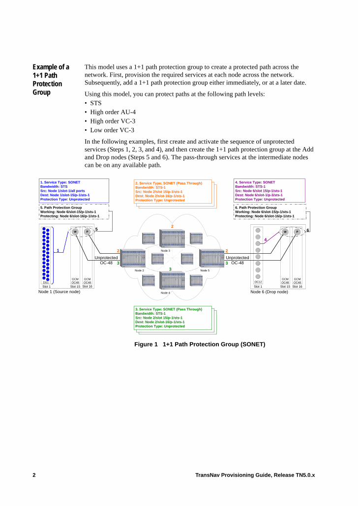
Example of a 1+1 Path Protection Group
This model uses a 1+1 path protection group to create a protected path across the network. First, provision the required services at each node across the network. Subsequently, add a 1+1 path protection group either immediately, or at a later date.
Using this model, you can protect paths at the following path levels:• STS• High order AU-4• High order VC-3• Low order VC-3
In the following examples, first create and activate the sequence of unprotected services (Steps 1, 2, 3, and 4), and then create the 1+1 path protection group at the Add and Drop nodes (Steps 5 and 6). The pass-through services at the intermediate nodes can be on any available path.
Figure 1 1+1 Path Protection Group (SONET)
Node 1 (Source node)Slot 1
GCMOC48
Slot 16
GCMOC48
Slot 15
1. Service Type: SONETBandwidth: STSSrc: Node 1/slot-1/all portsDest: Node 1/slot-15/p-1/sts-1Protection Type: Unprotected
UnprotectedOC-48
Node 6 (Drop node)Slot 1
GCMOC48
Slot 16
GCMOC48
Slot 15
OC12
4. Service Type: SONETBandwidth: STS-1Src: Node 6/slot 15/p-1/sts-1Dest: Node 6/slot-1/p-3/sts-1Protection Type: Unprotected
6. Path Protection GroupWorking: Node 6/slot-15/p-1/sts-1Protecting: Node 6/slot-16/p-1/sts-1
1 2
2
2
4
5. Path Protection GroupWorking: Node 6/slot-15/p-1/sts-1Protecting: Node 6/slot-16/p-1/sts-1
Node 4
Node 3
Node 2
PW
3
3
3
Node 5
W P 6
UnprotectedOC-48
5
3. Service Type: SONET (Pass Through)Bandwidth: STS-1Src: Node 2/slot 15/p-1/sts-1Dest: Node 2/slot-16/p-1/sts-1Protection Type: Unprotected
2. Service Type: SONET (Pass Through)Bandwidth: STS-1Src: Node 2/slot 15/p-1/sts-1Dest: Node 2/slot-16/p-1/sts-1Protection Type: Unprotected
DS1
2 TransNav Provisioning Guide, Release TN5.0.x

.
Figure 2 1+1 Path Protection Group (SDH)
Node 1 (Source node)Slot 1
GCMSTM16Slot 16
GCMSTM16Slot 15
1. Service Type: SDHBandwidth: VC3Src: Node 1/slot-1/all portsDest: Node 1/slot-15/p-1/a-1/vc3-1Protection Type: Unprotected
UnprotectedSTM-16
Node 6 (Drop node)Slot 1
GCMSTM16Slot 16
GCMSTM16Slot 15
STM4
4. Service Type: SDHBandwidth: VC3Src: Node 6/slot 15/p-1/a-1/vc3-1Dest: Node 6/slot-1/p-3/a-1/vc3-1Protection Type: Unprotected
6. Path Protection GroupWorking: Node 6/slot-15/p-1/a-1/vc3-1Protecting: Node 6/slot-16/p-1/a-1/vc3-1
1 2
2
2
4
5. Path Protection GroupWorking: Node 6/slot-15/p-1/a-1/vc3-1Protecting: Node 6/slot-16/p-1/a-1/vc3-1
Node 4
Node 3
Node 2
PW
3
3
3
Node 5
W P 6
UnprotectedSTM-16
5
E1
3. Service Type: SDH (Pass Through)Bandwidth VC3Src: Node 2/slot 15/p-1/a-1/vc3-1Dest: Node 2/slot-16/p-1/a-1/vc3-1Protection Type: Unprotected
2. Service Type: SDH (Pass Through)Bandwidth: VC3Src: Node 2/slot 15/p-1/a-1/vc3-1Dest: Node 2/slot-16/p-1/a-1/vc3-1Protection Type: Unprotected
TransNav Provisioning Guide, Release TN5.0.x 3
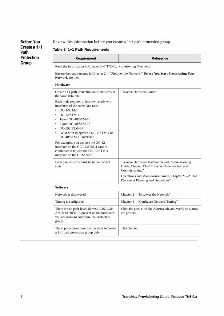
Before You Create a 1+1 Path Protection Group
Review this information before you create a 1+1 path protection group.
Table 3 1+1 Path Requirements
Requirement Reference
Read the information in Chapter 1—“TN5.0.x Provisioning Overview.”
Ensure the requirements in Chapter 2—“Discover the Network,” Before You Start Provisioning Your Network are met.
Hardware
Create 1+1 path protection on trunk cards of the same data rate:
Each node requires at least two cards with interfaces of the same data rate:• OC-3/STM-1 • OC-12/STM-4• 1-port OC-48/STM-16• 2-port OC-48/STM-16• OC-192/STM-64• GCM with integrated OC-12/STM-4 or
OC-48/STM-16 interface
For example, you can use the OC-12 interface on the OC-12/STM-4 card in combination to with the OC-12/STM-4 interface on the GCM card.
Traverse Hardware Guide
Each pair of cards must be in the correct slots.
Traverse Hardware Installation and Commissioning Guide, Chapter 13—“Traverse Node Start-up and Commissioning”
Operations and Maintenance Guide, Chapter 21—“Card Placement Planning and Guidelines”
Software
Network is discovered Chapter 2—“Discover the Network”
Timing is configured Chapter 3—“Configure Network Timing”
There are no path-level alarms (LOS, LOF, AIS-P, SF-BER-P) present on the interfaces you are using to configure the protection group.
Click the port, click the Alarms tab, and verify no alarms are present.
These procedures describe the steps to create a 1+1 path protection group only.
This chapter.
4 TransNav Provisioning Guide, Release TN5.0.x

Guidelines to Create a 1+1 Path Protection Group
The guidelines to create a 1+1 path protection group are:• Use the 1+1 path protection group model to protect services created at the following
path levels: – STS– High order AU-4– High order VC-3– Low order VC-3
• See Chapter 31—“Creating 1+1 Path Protected Services” for the complete procedure to create end-to-end path protection.
• The network interfaces at the source and drop nodes cannot be part of a 1+1 APS/MSPprotection group, an MS-SP ring, or a BLSR protection group. However, the interfaces can be part of a UPSR/SNCP protection group or unprotected.
• Provision the protection group after the initial service is provisioned. This sequence allows for in-service upgrades of any already activated service.
Create a 1+1 Path Protection Group
Use this procedure to create a 1+1 path protection group.
Table 4 Create a 1+1 Path Protection Group
Step Procedure
1 Review the information in Before You Create a 1+1 Path Protection Group before you start this procedure.
2 In Shelf View, click the Protection tab to display the Protection Groups screen.
3 Add a 1+1 path protection group. From the New list, select 1+1_path.
Figure 5 Select 1+1 Path
Step 4
TransNav Provisioning Guide, Release TN5.0.x 5

4 Click Add to display the Protection Group Creation tab and the Create 1+1 Protection Group screen.
Figure 6 Create 1 Plus 1 Protection Group
5 In the Name field, enter the name of the node (maximum of 43 characters). Use alphanumeric characters only. Do not use punctuation, spaces or any other special character in this field.
6 Select the protecting information.The ports must be of the same type on different cards.• Select the Protecting Port for this protection group. Click the
Protecting Port field and select the protecting port.• Select the Protection Path for this protection group. Click the
Protection Path field and select the protection path.
7 Select the working information.• Select the Working Port for this protection group. Click the Working
Port field and select the protecting port.• Select the Working Path for this protection group. Click the Working
Path field and select the protection path.
8 Select the bandwidth of the paths. From the Concatenation parameter, select the total bandwidth of the path. If the working and protecting endpoints are SONET endpoints, select from the following options: • 1 (default) for STS-1 paths• 3c for STS-3c• 12c for STS-12c paths (for OC-12 and greater interfaces only)• 48c for STS-48c paths (for OC-48 and greater interfaces only)
If the working and protecting endpoints are STM endpoints, select from the following options: • 1 for HO and LO VC-3 paths (default)• 4c for VC-4-4c paths• 16c for VC-4-16c paths (for STM-4 and greater interfaces only)
Table 4 Create a 1+1 Path Protection Group (continued)
Step Procedure
6 TransNav Provisioning Guide, Release TN5.0.x
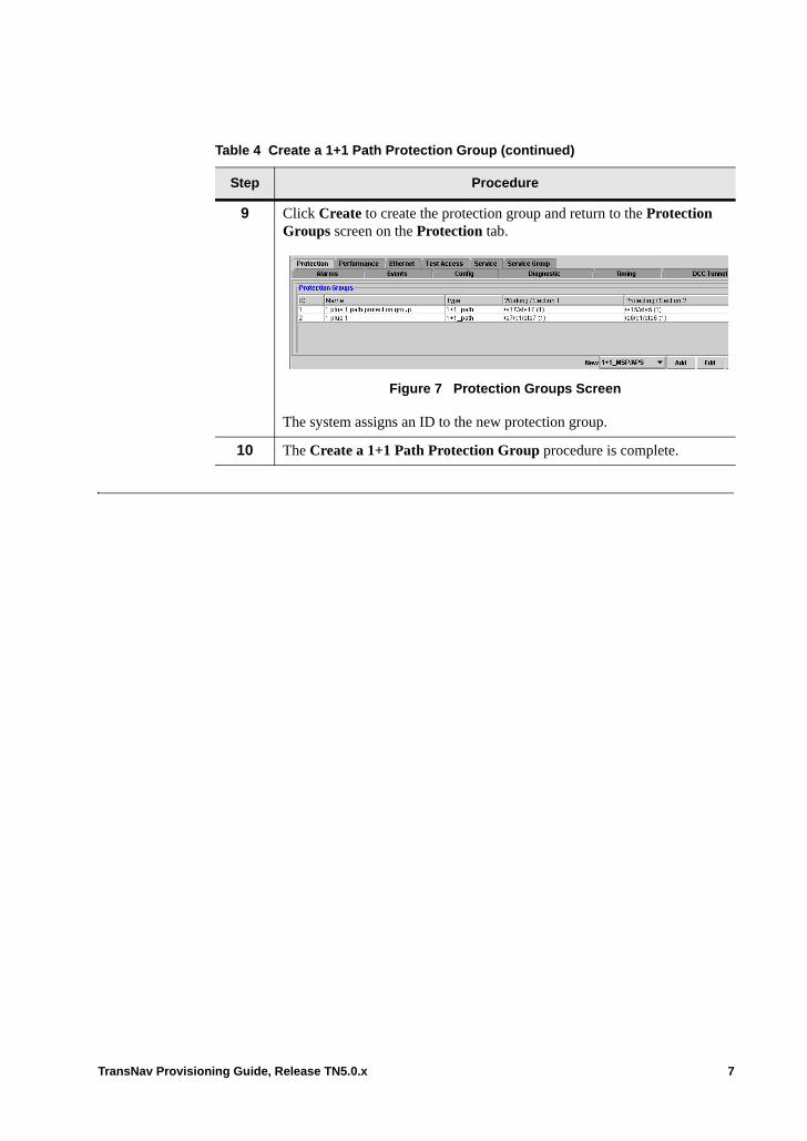
9 Click Create to create the protection group and return to the Protection Groups screen on the Protection tab.
Figure 7 Protection Groups Screen
The system assigns an ID to the new protection group.
10 The Create a 1+1 Path Protection Group procedure is complete.
Table 4 Create a 1+1 Path Protection Group (continued)
Step Procedure
TransNav Provisioning Guide, Release TN5.0.x 7

8 TransNav Provisioning Guide, Release TN5.0.x
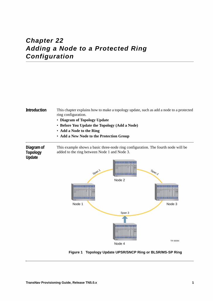
Chapter 22 Adding a Node to a Protected Ring Configuration
Introduction This chapter explains how to make a topology update, such as add a node to a protected ring configuration.• Diagram of Topology Update• Before You Update the Topology (Add a Node)• Add a Node to the Ring• Add a New Node to the Protection Group
Diagram of Topology Update
This example shows a basic three-node ring configuration. The fourth node will be added to the ring between Node 1 and Node 3.
Figure 1 Topology Update UPSR/SNCP Ring or BLSR/MS-SP Ring
Node 2
Node 3Node 1
Node 4
Span 1 Span 2
Span 3
TR 00094
TransNav Provisioning Guide, Release TN5.0.x 1

Before You Update the Topology (Add a Node)
Review this information before you add a node to a protected ring configuration.
Table 2 Add Node Requirements
Requirement Reference
Hardware
New node is installed and commissioned. However, the fibers ARE NOT yet connected to the other nodes in the existing network.
Hardware Installation and Commissioning Guide, Chapter 13—“Traverse Node Start-up and Commissioning”
All nodes in the ring have the same version of software.
If upgrades are required, contact your Force10 customer representative.
not applicable
Software
Timing is configured for the new node. Chapter 3—“Configure Network Timing”
For hop-by-hop services, preprovision the pass-through services on the new node.
Chapter 27—“Configuring SONET Services”
or Chapter 29—“Configuring SDH Services”
2 TransNav Provisioning Guide, Release TN5.0.x

Add a Node to the Ring
Use this procedure as a guideline to update a topology (add a new node to the ring).
Important: When adding a node to a UPSR ring with end-to-end provisioning, make sure there are no LOS conditions through the network when the node is added. Existing LOS conditions will result in an Add Node refresh failure or refresh in progress state. If this interim Add Node state exists, stop any further span provisioning tasks and contact the Force10 Technical Assistance Center.
After the new node has been added to the ring, replace the source or destination endpoint from the original service with the source or destination endpoint of the added node. For example, a service exists between Node A and Node B and the source endpoint is on Node A Slot 1. If Node C is added between Node A and Node B, the source endpoint must be changed from Node A Slot 1 to Node C Slot 3.
From:Node A (s1) <----> (s2) Node B
To:Node A (s1) <----> (s3) Node C
Table 3 Add a Node to the Ring
Step Procedure
1 Read the guidelines in the topic Before You Update the Topology (Add a Node).
2 Force switch the traffic off both the near end and the far end of the fiber span that will be disconnected to add the new node. (Span 3 in the example Topology Update UPSR/SNCP Ring or BLSR/MS-SP Ring).
For a BLSR/MS-SP Ring, go to Step 3.
For a UPSR/SNCP Ring, go to Step 4.
3 Force-switch the traffic off a span in a BLSR/MS-SP Ring:
a. In Map View, click the Protection tab.
b. Click the protection group to select it and click Edit.
c. Select the near end port. Right-click and select Forced (FS-R).
d. Select the far end port. Right-click and select Forced (FS-R).
e. Go to Step 5.
TransNav Provisioning Guide, Release TN5.0.x 3
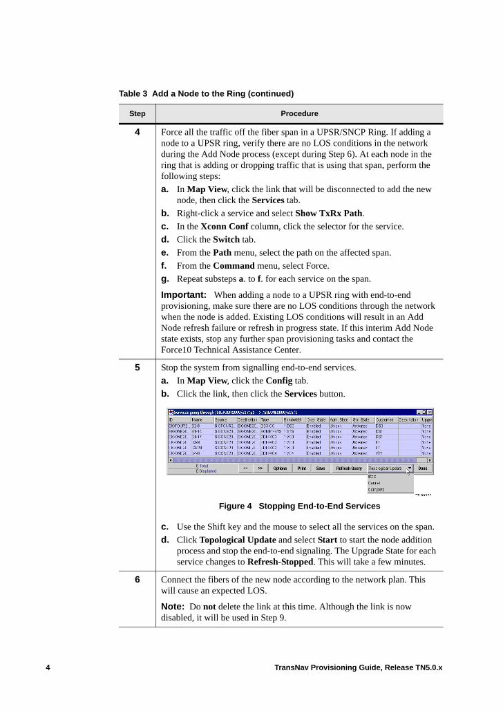
4 Force all the traffic off the fiber span in a UPSR/SNCP Ring. If adding a node to a UPSR ring, verify there are no LOS conditions in the network during the Add Node process (except during Step 6). At each node in the ring that is adding or dropping traffic that is using that span, perform the following steps:
a. In Map View, click the link that will be disconnected to add the new node, then click the Services tab.
b. Right-click a service and select Show TxRx Path.
c. In the Xconn Conf column, click the selector for the service.
d. Click the Switch tab.
e. From the Path menu, select the path on the affected span.
f. From the Command menu, select Force.
g. Repeat substeps a. to f. for each service on the span.
Important: When adding a node to a UPSR ring with end-to-end provisioning, make sure there are no LOS conditions through the network when the node is added. Existing LOS conditions will result in an Add Node refresh failure or refresh in progress state. If this interim Add Node state exists, stop any further span provisioning tasks and contact the Force10 Technical Assistance Center.
5 Stop the system from signalling end-to-end services.
a. In Map View, click the Config tab.
b. Click the link, then click the Services button.
Figure 4 Stopping End-to-End Services
c. Use the Shift key and the mouse to select all the services on the span.
d. Click Topological Update and select Start to start the node addition process and stop the end-to-end signaling. The Upgrade State for each service changes to Refresh-Stopped. This will take a few minutes.
6 Connect the fibers of the new node according to the network plan. This will cause an expected LOS.
Note: Do not delete the link at this time. Although the link is now disabled, it will be used in Step 9.
Table 3 Add a Node to the Ring (continued)
Step Procedure
4 TransNav Provisioning Guide, Release TN5.0.x
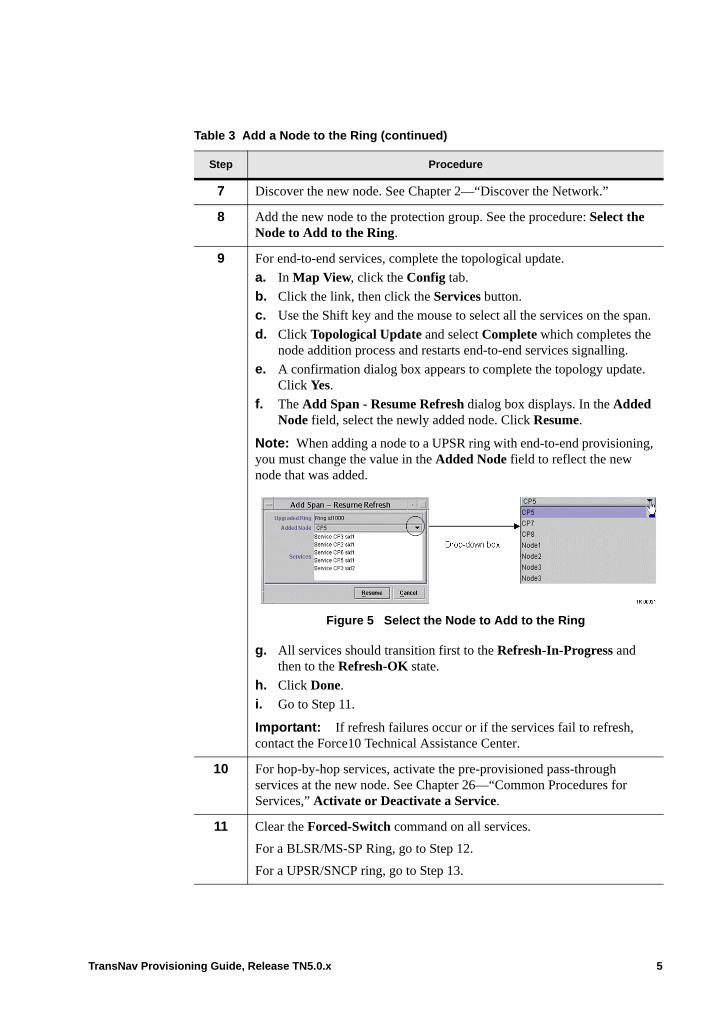
7 Discover the new node. See Chapter 2—“Discover the Network.”
8 Add the new node to the protection group. See the procedure: Select the Node to Add to the Ring.
9 For end-to-end services, complete the topological update.
a. In Map View, click the Config tab.
b. Click the link, then click the Services button.
c. Use the Shift key and the mouse to select all the services on the span.
d. Click Topological Update and select Complete which completes the node addition process and restarts end-to-end services signalling.
e. A confirmation dialog box appears to complete the topology update. Click Yes.
f. The Add Span - Resume Refresh dialog box displays. In the Added Node field, select the newly added node. Click Resume.
Note: When adding a node to a UPSR ring with end-to-end provisioning, you must change the value in the Added Node field to reflect the new node that was added.
Figure 5 Select the Node to Add to the Ring
g. All services should transition first to the Refresh-In-Progress and then to the Refresh-OK state.
h. Click Done.
i. Go to Step 11.
Important: If refresh failures occur or if the services fail to refresh, contact the Force10 Technical Assistance Center.
10 For hop-by-hop services, activate the pre-provisioned pass-through services at the new node. See Chapter 26—“Common Procedures for Services,” Activate or Deactivate a Service.
11 Clear the Forced-Switch command on all services.
For a BLSR/MS-SP Ring, go to Step 12.
For a UPSR/SNCP ring, go to Step 13.
Table 3 Add a Node to the Ring (continued)
Step Procedure
TransNav Provisioning Guide, Release TN5.0.x 5
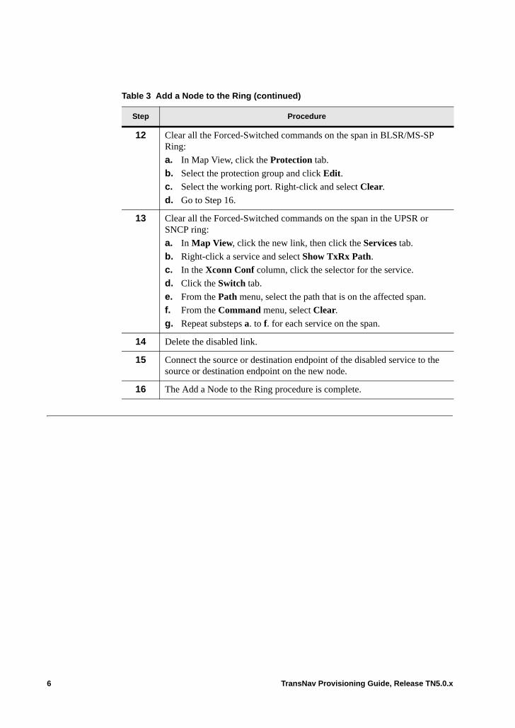
12 Clear all the Forced-Switched commands on the span in BLSR/MS-SP Ring:
a. In Map View, click the Protection tab.
b. Select the protection group and click Edit.
c. Select the working port. Right-click and select Clear.
d. Go to Step 16.
13 Clear all the Forced-Switched commands on the span in the UPSR or SNCP ring:
a. In Map View, click the new link, then click the Services tab.
b. Right-click a service and select Show TxRx Path.
c. In the Xconn Conf column, click the selector for the service.
d. Click the Switch tab.
e. From the Path menu, select the path that is on the affected span.
f. From the Command menu, select Clear.
g. Repeat substeps a. to f. for each service on the span.
14 Delete the disabled link.
15 Connect the source or destination endpoint of the disabled service to the source or destination endpoint on the new node.
16 The Add a Node to the Ring procedure is complete.
Table 3 Add a Node to the Ring (continued)
Step Procedure
6 TransNav Provisioning Guide, Release TN5.0.x

Add a New Node to the Protection Group
Use this procedure to add a new node to a UPSR/SNCP Ring or BLSR/MS-SP Ring protection group.
Note: If you have a ‘Disabled optical link, do not delete it until you complete the procedure. The optical link is used to refresh end-to-end services.
Table 6 Add the New Node to the Protection Group
Step Procedure
1 Complete steps Steps 1 through 7 in the procedure Add a Node to the Ring.
2 Force switch the traffic off both the near-end and far end of the fiber span that will be disconnected to add the new node.
For BLSR/MS-SP Ring, go to Step Step 3.
For UPSR/SNCP Ring, go to Step Step 4.
3 Force switch the traffic off a span in a BLSR/MS-SP Ring. In Map View, click the link that will be disconnected to add the new node, then click the Services tab.
a. Select the protection group to which you want to add the node and click Edit. The Protection Group Creation tab displays.
b. Select the near end port. Right-click and select Forced (FS-R).
c. Select the far end port. Right-click and select Forced (FS-R).
Go to Step 5.
4 Force switch the traffic off a span in a UPSR/SNCP Ring. In Map View, click the Protection tab.
a. Select the protection group to which you want to add the node and click Edit. The Protection Group Creation tab displays.
b. Right-click a service and select Show TXRx Path.
c. In the XConn Conf column, click the selector for the service.
d. Click the Switch tab.
e. From the Path menu, select the path that is on the affected span.
f. From the Command menu, select Force.
g. Repeat Steps a through f for each service on the span.
Go to Step 5.
TransNav Provisioning Guide, Release TN5.0.x 7

5 Stop the system from signaling end-to-end services.
Important: When adding a node to a UPSR ring that has end-to-end services provisioned, make sure there are no LOS conditions through the network when the node is added. Existing LOS conditons will result in an Add Node refresh failure or refresh in progress state. If this interim Add Node state exists, stop any further span provisioning tasks and contact Force10 TAC.
a. In Map View, click the Config tab.
b. Click the link then click the Services button. A screen displays listing all of the services going through that link.
c. Use the Shift key and mouse to all of the services on the span.
d. Click Topological Update in the bottom right corner of the screen and select Start to start the node addition process. This also stops the end-to-end signaling. The Upgrade State changes to Refresh-Stopped.
6 Connect the fibers of the new node according to the network plan.
7 Discover the new node. For more information see Chapter 2—“Discover the Network,” Discover the Network.
8 Add the new node to the protection group. For more information, see Add a Node to the Ring.
Table 6 Add the New Node to the Protection Group (continued)
Step Procedure
8 TransNav Provisioning Guide, Release TN5.0.x
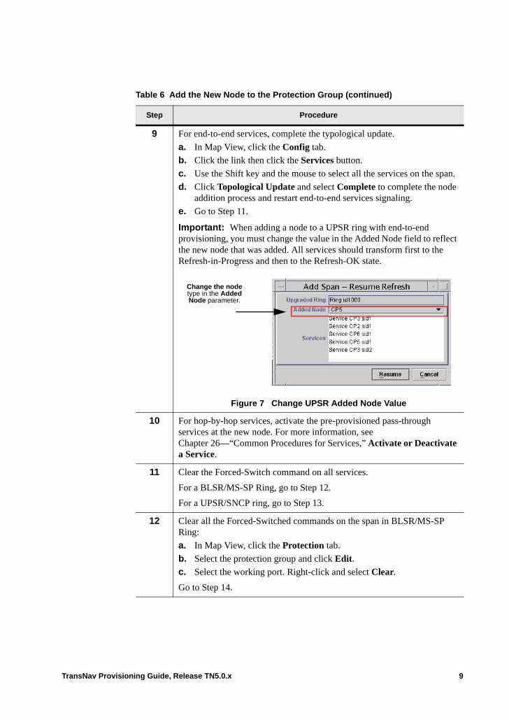
9 For end-to-end services, complete the typological update.
a. In Map View, click the Config tab.
b. Click the link then click the Services button.
c. Use the Shift key and the mouse to select all the services on the span.
d. Click Topological Update and select Complete to complete the node addition process and restart end-to-end services signaling.
e. Go to Step 11.
Important: When adding a node to a UPSR ring with end-to-end provisioning, you must change the value in the Added Node field to reflect the new node that was added. All services should transform first to the Refresh-in-Progress and then to the Refresh-OK state.
Figure 7 Change UPSR Added Node Value
10 For hop-by-hop services, activate the pre-provisioned pass-through services at the new node. For more information, see Chapter 26—“Common Procedures for Services,” Activate or Deactivate a Service.
11 Clear the Forced-Switch command on all services.
For a BLSR/MS-SP Ring, go to Step 12.
For a UPSR/SNCP ring, go to Step 13.
12 Clear all the Forced-Switched commands on the span in BLSR/MS-SP Ring:
a. In Map View, click the Protection tab.
b. Select the protection group and click Edit.
c. Select the working port. Right-click and select Clear.
Go to Step 14.
Table 6 Add the New Node to the Protection Group (continued)
Step Procedure
Change the node type in the Added Node parameter.
TransNav Provisioning Guide, Release TN5.0.x 9
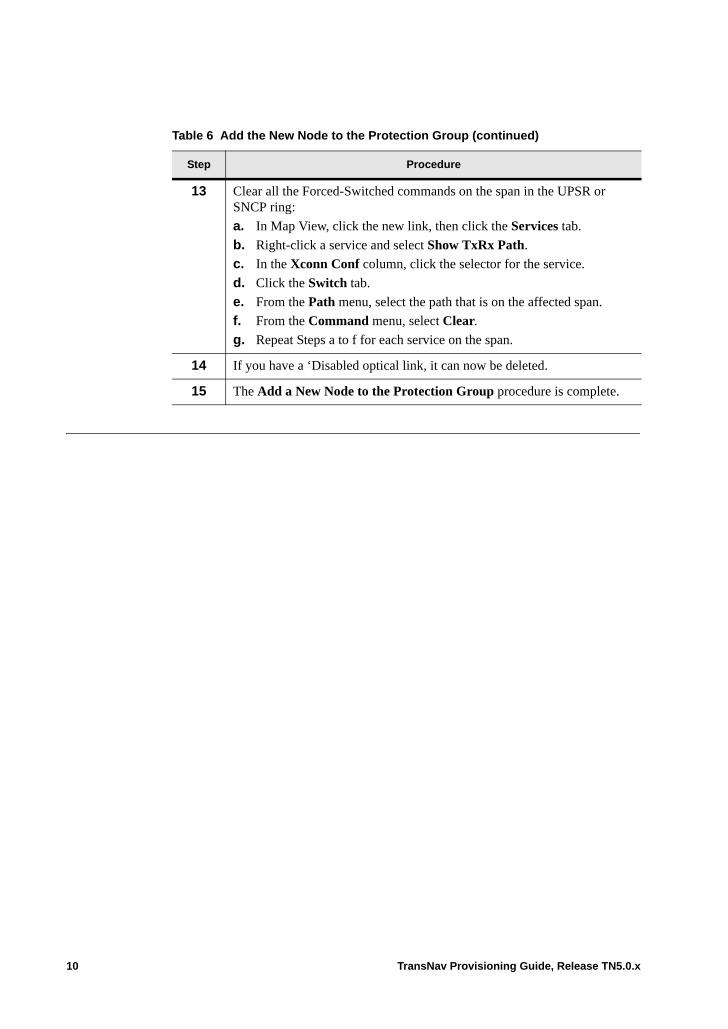
13 Clear all the Forced-Switched commands on the span in the UPSR or SNCP ring:
a. In Map View, click the new link, then click the Services tab.
b. Right-click a service and select Show TxRx Path.
c. In the Xconn Conf column, click the selector for the service.
d. Click the Switch tab.
e. From the Path menu, select the path that is on the affected span.
f. From the Command menu, select Clear.
g. Repeat Steps a to f for each service on the span.
14 If you have a ‘Disabled optical link, it can now be deleted.
15 The Add a New Node to the Protection Group procedure is complete.
Table 6 Add the New Node to the Protection Group (continued)
Step Procedure
10 TransNav Provisioning Guide, Release TN5.0.x

Chapter 23 Creating a 1+1 Optimized Protection Group
Introduction 1+1 optimized protection bridges traffic in an SDH network simultaneously over two lines: section 1 and section 2. There is a primary section and a secondary section.
In normal operation, the system selects traffic from the primary section (active traffic). All switch requests (automatic or forced) are from the primary section to the secondary section. Once a switch request clears, the traffic selector stays on the section to which it was switched. That section then becomes the primary section if there are no further switch requests.
If a failure occurs on the secondary section, the traffic selector remains on traffic from the primary section. If a failure occurs on the secondary section during a protection switch, the initial switch request is abandoned.
This chapter contains the following information:• Before You Create a 1+1 Optimized Protection Group• Create a 1+1 Optimized Protection Group• Protection Switch Commands• Request Priorities for 1+1 Optimized Protection
TransNav Provisioning Guide, Release TN5.0.x 1
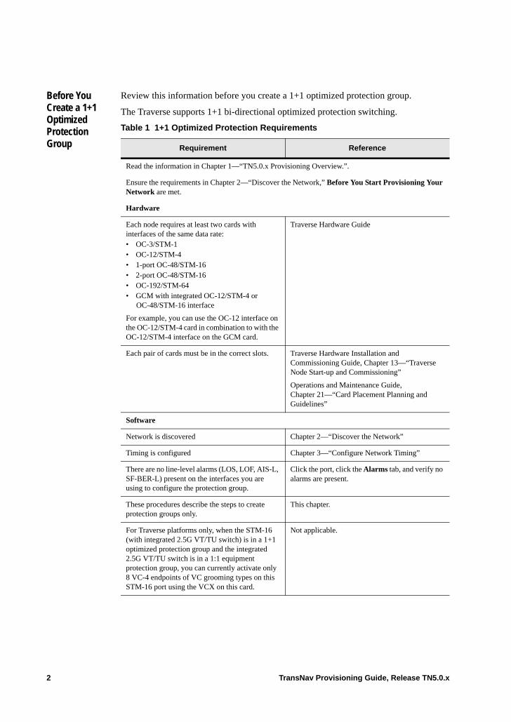
Before You Create a 1+1 Optimized Protection Group
Review this information before you create a 1+1 optimized protection group.
The Traverse supports 1+1 bi-directional optimized protection switching.
Table 1 1+1 Optimized Protection Requirements
Requirement Reference
Read the information in Chapter 1—“TN5.0.x Provisioning Overview.”.
Ensure the requirements in Chapter 2—“Discover the Network,” Before You Start Provisioning Your Network are met.
Hardware
Each node requires at least two cards with interfaces of the same data rate:• OC-3/STM-1• OC-12/STM-4• 1-port OC-48/STM-16• 2-port OC-48/STM-16• OC-192/STM-64• GCM with integrated OC-12/STM-4 or
OC-48/STM-16 interface
For example, you can use the OC-12 interface on the OC-12/STM-4 card in combination to with the OC-12/STM-4 interface on the GCM card.
Traverse Hardware Guide
Each pair of cards must be in the correct slots. Traverse Hardware Installation and Commissioning Guide, Chapter 13—“Traverse Node Start-up and Commissioning”
Operations and Maintenance Guide, Chapter 21—“Card Placement Planning and Guidelines”
Software
Network is discovered Chapter 2—“Discover the Network”
Timing is configured Chapter 3—“Configure Network Timing”
There are no line-level alarms (LOS, LOF, AIS-L, SF-BER-L) present on the interfaces you are using to configure the protection group.
Click the port, click the Alarms tab, and verify no alarms are present.
These procedures describe the steps to create protection groups only.
This chapter.
For Traverse platforms only, when the STM-16 (with integrated 2.5G VT/TU switch) is in a 1+1 optimized protection group and the integrated 2.5G VT/TU switch is in a 1:1 equipment protection group, you can currently activate only 8 VC-4 endpoints of VC grooming types on this STM-16 port using the VCX on this card.
Not applicable.
2 TransNav Provisioning Guide, Release TN5.0.x
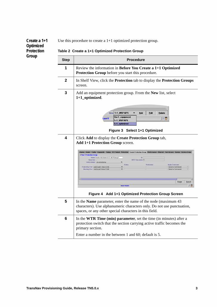
Create a 1+1 Optimized Protection Group
Use this procedure to create a 1+1 optimized protection group.
Table 2 Create a 1+1 Optimized Protection Group
Step Procedure
1 Review the information in Before You Create a 1+1 Optimized Protection Group before you start this procedure.
2 In Shelf View, click the Protection tab to display the Protection Groups screen.
3 Add an equipment protection group. From the New list, select 1+1_optimized.
Figure 3 Select 1+1 Optimized
4 Click Add to display the Create Protection Group tab, Add 1+1 Protection Group screen.
Figure 4 Add 1+1 Optimized Protection Group Screen
5 In the Name parameter, enter the name of the node (maximum 43 characters). Use alphanumeric characters only. Do not use punctuation, spaces, or any other special characters in this field.
6 In the WTR Time (min) parameter, set the time (in minutes) after a protection switch that the section carrying active traffic becomes the primary section.
Enter a number in the between 1 and 60; default is 5.
TransNav Provisioning Guide, Release TN5.0.x 3
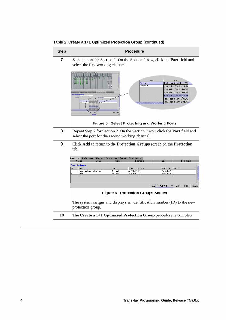
7 Select a port for Section 1. On the Section 1 row, click the Port field and select the first working channel.
Figure 5 Select Protecting and Working Ports
8 Repeat Step 7 for Section 2. On the Section 2 row, click the Port field and select the port for the second working channel.
9 Click Add to return to the Protection Groups screen on the Protection tab.
Figure 6 Protection Groups Screen
The system assigns and displays an identification number (ID) to the new protection group.
10 The Create a 1+1 Optimized Protection Group procedure is complete.
Table 2 Create a 1+1 Optimized Protection Group (continued)
Step Procedure
4 TransNav Provisioning Guide, Release TN5.0.x
Protection Switch Commands
You can edit the protection group from the Protection tab in two ways:• Highlight the protection group and right-click; select Edit.• Double-click the protection group.
The switch commands differ between the protecting and working ports as indicated below.
Primary State Commands. Right-click the primary facility to display the switch commands. See Request Priorities for 1+1 Optimized Protection for the switch command priorities.• Clear: Clear all switch commands from the port. • Lockout: Local request that freezes the selector position and the transmission of
kilobytes on the current position until this request is cleared.• Forced: Force the system to select traffic from the secondary section, unless a local
lockout is in effect, an equal or higher priority request is in effect, or the secondary section has failed.
Secondary State Commands. Right-click the secondary state port to display the switch commands. See Request Priorities for 1+1 Optimized Protection for the switch command priorities.• Clear: Clear all switch commands from the port. • Lockout: Local request that freezes the selector position and the transmission of
kilobytes on the current position until this request is cleared.
Request Priorities for 1+1 Optimized Protection
Request priorities (from highest to lowest) for 1+1 optimized protection switching are:• Forced (near end or far end)• Signal Fail (near end or far end)• Signal Degrade (near end or far end)• Wait-to-Restore (near end or far end)
TransNav Provisioning Guide, Release TN5.0.x 5

6 TransNav Provisioning Guide, Release TN5.0.x
Chapter 24 Service Provisioning Concepts
Introduction Creating services in a Traverse network requires that you first identify switching requirements, bandwidth requirements, and service types. This chapter explains the particulars of services on a Traverse platform: • Traverse Services Definition• Supported Features• Transport Capacity• Traverse Service Types• Service Creation Models• End-to-End Services Over Mixed Topologies• Basic ADM Service Creation Process• Before You Start Creating Services
If your system includes 2-port OC-48 cards, see Chapter 6—“Creating 2-Port OC-48/STM-16 Services” for additional information.
Traverse Services Definition
A service in a TransNav managed network connects traffic from a source to a destination. The source can be a port, subport, channel, or path. The source originates on any card.
The destination of the service varies depending on the connection you are creating. The destination can be a compatible card, port, subport, or another service. Additionally, the destination can be on the same node or on a separate node.
There are three types of services on a Traverse system: regular SONET or SDH, Ethernet, or VC-Bundle for transport of Ethernet services.
Supported Features
DS3 Transmux
Transmultiplexing functionality is provided by the Traverse DS3/EC-1 Transmux card. This capability is important in applications where incoming traffic is channelized DS3 and the payload of the outgoing circuit needs to be VT-mapped, such as those that are handed off to the Traverse switch fabric.
TransNav Provisioning Guide, Release TN5.0.x 1
Bridging and Rolling
The Traverse system supports transferring services from one facility to another without dropping traffic. See Chapter 32—“Bridging and Rolling Services.”
Multicast Connections
Multicast connections are connections made from one source to multiple destinations. The Traverse system supports multicast connections for the following services:• SONET-STS• SONET-VT• Ethernet• SDH-VC4• SDH-VC3
Use multicast connections to create drop-and-continue services in a network of Traverse nodes.
Optical Transmux
The Transmux component also transparently provides this transmux capability when traffic ingresses and egresses the Traverse system using an optical interface. In this case, the Transmux component receives incoming DS1/E1-mapped DS3s from the Traverse backplane and converts the outgoing signal to VT-mapped STS-1s or VC-mapped AU-3s.
Resource Advisory
If this feature is enabled, the system displays only available resources. Ports, paths, endpoints, and other resources assigned to activated services appear in the graphical user interface with an asterisk (*). The system also displays available capabilities for resource limitations, such as [DS1 / VT Capable].
SDH to SONET Interworking
The Traverse platform supports SDH to SONET interworking capabilities. That is, you can connect an SDH signal to a SONET signal.
The Traverse supports the following gateway services:• DS1 over SDH• E1 over SDH• SDH to SONET• SONET to SDH
VT/VC Switching
Force10 offers the following options to switch traffic at the VT/VC levels:• VT/TU 5G Switch card• VTX/VCX integrated cards• VT-HD 35G Switch card
See the Traverse Hardware Guide, Chapter 12—“VT/VC Switching Cards” for detailed descriptions of these VT/VC switching options.
2 TransNav Provisioning Guide, Release TN5.0.x

Automatic In Service
Available on Traverse systems only, this feature allows the automatic suppression of SONET optical and electrical port-level and service-level alarms and performance maintenance reports when traffic is not activated on a service. This is useful when pre-provisioning services or during maintenance periods.
Note: The Automatic In Service (AINS) feature is not available on Ethernet services.
TransNav Provisioning Guide, Release TN5.0.x 3
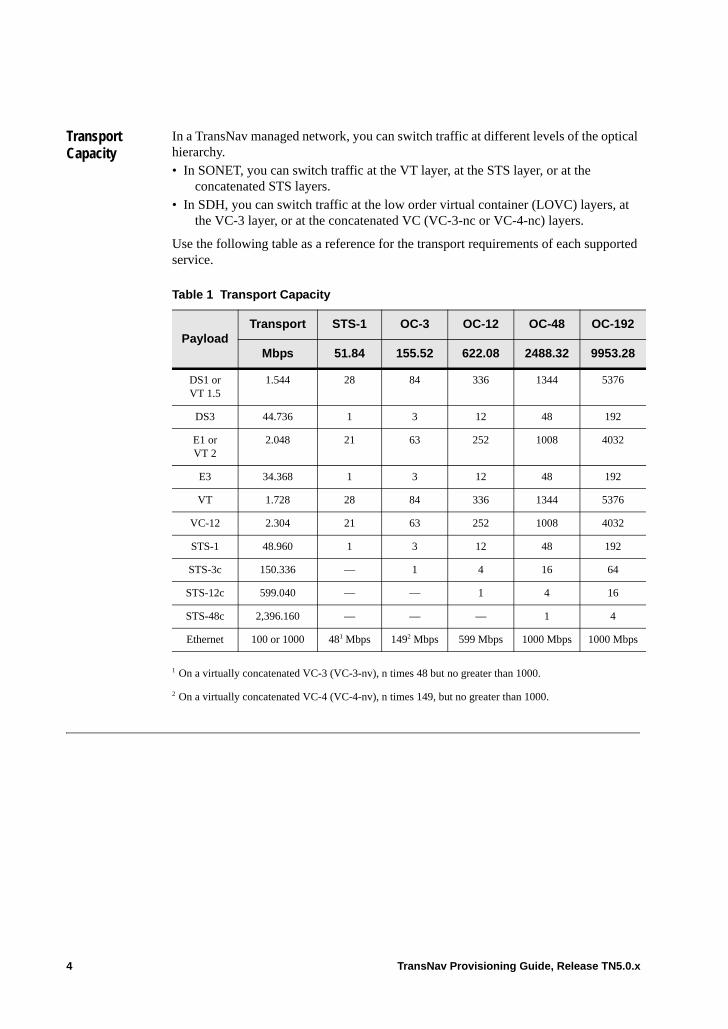
Transport Capacity
In a TransNav managed network, you can switch traffic at different levels of the optical hierarchy. • In SONET, you can switch traffic at the VT layer, at the STS layer, or at the
concatenated STS layers. • In SDH, you can switch traffic at the low order virtual container (LOVC) layers, at
the VC-3 layer, or at the concatenated VC (VC-3-nc or VC-4-nc) layers.
Use the following table as a reference for the transport requirements of each supported service.
Table 1 Transport Capacity
PayloadTransport STS-1 OC-3 OC-12 OC-48 OC-192
Mbps 51.84 155.52 622.08 2488.32 9953.28
DS1 or VT 1.5
1.544 28 84 336 1344 5376
DS3 44.736 1 3 12 48 192
E1 or VT 2
2.048 21 63 252 1008 4032
E3 34.368 1 3 12 48 192
VT 1.728 28 84 336 1344 5376
VC-12 2.304 21 63 252 1008 4032
STS-1 48.960 1 3 12 48 192
STS-3c 150.336 — 1 4 16 64
STS-12c 599.040 — — 1 4 16
STS-48c 2,396.160 — — — 1 4
Ethernet 100 or 1000 481 Mbps
1 On a virtually concatenated VC-3 (VC-3-nv), n times 48 but no greater than 1000.
1492 Mbps
2 On a virtually concatenated VC-4 (VC-4-nv), n times 149, but no greater than 1000.
599 Mbps 1000 Mbps 1000 Mbps
4 TransNav Provisioning Guide, Release TN5.0.x
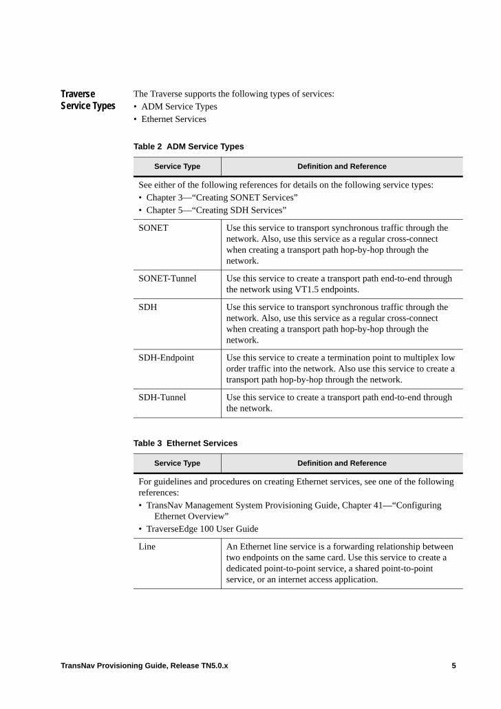
Traverse Service Types
The Traverse supports the following types of services:• ADM Service Types• Ethernet Services
Table 2 ADM Service Types
Service Type Definition and Reference
See either of the following references for details on the following service types:• Chapter 3—“Creating SONET Services”• Chapter 5—“Creating SDH Services”
SONET Use this service to transport synchronous traffic through the network. Also, use this service as a regular cross-connect when creating a transport path hop-by-hop through the network.
SONET-Tunnel Use this service to create a transport path end-to-end through the network using VT1.5 endpoints.
SDH Use this service to transport synchronous traffic through the network. Also, use this service as a regular cross-connect when creating a transport path hop-by-hop through the network.
SDH-Endpoint Use this service to create a termination point to multiplex low order traffic into the network. Also use this service to create a transport path hop-by-hop through the network.
SDH-Tunnel Use this service to create a transport path end-to-end through the network.
Table 3 Ethernet Services
Service Type Definition and Reference
For guidelines and procedures on creating Ethernet services, see one of the following references:• TransNav Management System Provisioning Guide, Chapter 41—“Configuring
Ethernet Overview” • TraverseEdge 100 User Guide
Line An Ethernet line service is a forwarding relationship between two endpoints on the same card. Use this service to create a dedicated point-to-point service, a shared point-to-point service, or an internet access application.
TransNav Provisioning Guide, Release TN5.0.x 5

End-to-End Services Over Mixed Topologies
The TransNav management system supports creating uni- and bi-directional end-to-end services over the following topologies on Traverse nodes only:• up to four single-node interconnected UPSR or SNCP rings• single-node interconnected UPSR and 1+1 APS linear chains• single-node interconnected SNCP rings and 1+1 MSP linear chains• up to three interconnected BLSRs or MS-SPRings• single-node interconnected BLSR and 1+1 MSP linear chains• single-node interconnected MS-SPRings and 1+1 MSP linear chains• single-node interconnected BLSR, UPSR, and 1+1 APS linear chains• single-node interconnected MS-SPRings, SNCP rings, and 1+1 MSP linear chains• multi-node mesh topology for STS and VT 1+1 path protection, high order and low
order SNCP rings
All hop information for the entire Low Order end-to-end service is kept on the source node. Additional resources, including memory, are consumed on the head node. Depending on the loading at the head node, this may result in limitations on the number of end-to-end services ingressing from a node.
For Low Order end-to-end services, the source endpoint must be the same for both the Unprotected and the 1+1 Path Protected service. This service model will be common
Bridge A bridge service is a forwarding relationship between an arbitrary number of endpoints on the same card. Any of the endpoints can be shared (by VLAN ID) with other services. Within a single bridge service, a packet is forwarded to one endpoint or to all endpoints using standard MAC address forwarding rules. Use this service to create a Virtual LAN Service application in the network.
Aggregation Bridge An aggregation bridge service is a hybrid of a line service and a bridge service. It is a forwarding relationship between a set of endpoints on a card, where one endpoint is considered the aggregation port and the other endpoints are considered ordinary members of the service.
Traffic received on the aggregation port is forwarded just as in a bridge service – to one or more ordinary members based on the destination MAC address. Traffic received on the ordinary members of the service is forwarded directly to the single aggregation port.
Multipoint ECC A multipoint ECC service provides a connection between a CPE (customer premise equipment) device and an EoPDH card on the Traverse using a bonded set of PDH links, such as DS1.
Table 3 Ethernet Services (continued)
Service Type Definition and Reference
6 TransNav Provisioning Guide, Release TN5.0.x
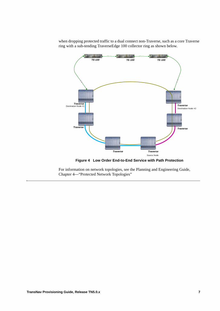
when dropping protected traffic to a dual connect non-Traverse, such as a core Traverse ring with a sub-tending TraverseEdge 100 collector ring as shown below.
Figure 4 Low Order End-to-End Service with Path Protection
For information on network topologies, see the Planning and Engineering Guide, Chapter 4—“Protected Network Topologies”
Traverse
TraverseDestination Node #2
Traverse
Traverse
Traverse
Traverse
OC
48 OC
48
TE-100 TE-100TE-100
STS1 #1 STS1 #1
Source Node
Destination Node #1
TransNav Provisioning Guide, Release TN5.0.x 7
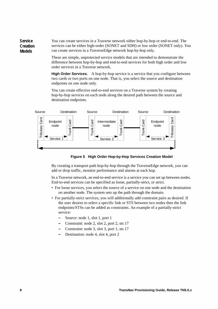
Service Creation Models
You can create services in a Traverse network either hop-by-hop or end-to-end. The services can be either high-order (SONET and SDH) or low order (SONET only). You can create services in a TraverseEdge network hop-by-hop only.
These are simple, unprotected service models that are intended to demonstrate the difference between hop-by-hop and end-to-end services for both high order and low order services in a Traverse network.
High Order Services. A hop-by-hop service is a service that you configure between two cards or two ports on one node. That is, you select the source and destination endpoints on one node only.
You can create effective end-to-end services on a Traverse system by creating hop-by-hop services on each node along the desired path between the source and destination endpoints.
Figure 5 High Order Hop-by-Hop Services Creation Model
By creating a transport path hop-by-hop through the TraverseEdge network, you can add or drop traffic, monitor performance and alarms at each hop.
In a Traverse network, an end-to-end service is a service you can set up between nodes. End-to-end services can be specified as loose, partially-strict, or strict. • For loose services, you select the source of a service on one node and the destination
on another node. The system sets up the path through the domain.• For partially-strict services, you will additionally add constraint pairs as desired. If
the user desires to select a specific link or STS between two nodes then the link endpoints/STSs can be added as constraints. An example of a partially-strict service:– Source: node 1, slot 1, port 1– Constraint: node 2, slot 2, port 2, sts 17– Constraint: node 3, slot 3, port 1, sts 17– Destination: node 4, slot 4, port 2
Source Destination Source Destination Source Destination
Trib
utar
y C
ard
Tru
nk C
ard
Tru
nk C
ard
Tru
nk C
ard
Tru
nk C
ard
Trib
utar
y C
ard
Intermediate node
Endpoint node
Endpoint node
Service 1 Service 3Service 2
8 TransNav Provisioning Guide, Release TN5.0.x
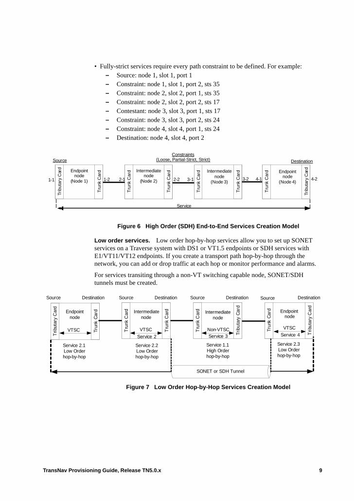
• Fully-strict services require every path constraint to be defined. For example: – Source: node 1, slot 1, port 1– Constraint: node 1, slot 1, port 2, sts 35– Constraint: node 2, slot 2, port 1, sts 35– Constraint: node 2, slot 2, port 2, sts 17– Contestant: node 3, slot 3, port 1, sts 17– Constraint: node 3, slot 3, port 2, sts 24– Constraint: node 4, slot 4, port 1, sts 24– Destination: node 4, slot 4, port 2
Figure 6 High Order (SDH) End-to-End Services Creation Model
Low order services. Low order hop-by-hop services allow you to set up SONET services on a Traverse system with DS1 or VT1.5 endpoints or SDH services with E1/VT11/VT12 endpoints. If you create a transport path hop-by-hop through the network, you can add or drop traffic at each hop or monitor performance and alarms.
For services transiting through a non-VT switching capable node, SONET/SDH tunnels must be created.
Figure 7 Low Order Hop-by-Hop Services Creation Model
Trib
utar
y C
ard
Tru
nk C
ard
Tru
nk C
ardIntermediate
node(Node 2)
Endpoint node
(Node 1)
Intermediate node
(Node 3)
Constraints(Loose, Partial-Strict, Strict)Source Destination
2-2 3-23-11-2 2-11-1
Tru
nk C
ard
Tru
nk C
ard
Tru
nk C
ard
Tru
nk C
ard
Trib
utar
y C
ard
Endpoint node
(Node 4)4-24-1
Service
Trun
k C
ard
Trib
utar
y C
ard
Source Destination
Trib
utar
y C
ard
Trun
k C
ard
Tru
nk C
ard
Tru
nk C
ard
Tru
nk C
ard
Trib
utar
y C
ard
Intermediate node
Endpoint node
Endpoint node
Source Destination Source Destination Source Destination
Service 2.1Low Order hop-by-hop
Service 3Service 2
Intermediate node
Service 4VTSC VTSC VTSCNon-VTSC
Service 2.2 Low Order hop-by-hop
Service 2.3Low Order hop-by-hop
Service 1.1High Order hop-by-hop
SONET or SDH Tunnel
TransNav Provisioning Guide, Release TN5.0.x 9

Low order end-to-end services allow you to set up SONET services on a Traverse system with DS1 or VT1.5 endpoints and can be specified as fully loose or fully strict. Low order end-to-end services are available only on SONET services.
Figure 8 Low Order (SONET) End-to-End Services Creation Model
Basic ADM Service Creation Process
Use the following steps to create an ADM service in the Traverse and TE-100 systems.
Trib
utar
y C
ard
Tru
nk C
ard
Tru
nk C
ardIntermediate
node(Node 2)
Endpoint node
(Node 1)
Intermediate node
(Node 3)
Constraints(Loose, Strict)Source Destination
2-2 3-23-11-2 2-11-1
Tru
nk C
ard
Tru
nk C
ard
Tru
nk C
ard
Tru
nk C
ard
Trib
utar
y C
ard
Endpoint node
(Node 4)4-24-1
Tru
nk C
ard
VTSC VTSC VTSCNon-VTSC
SONET Tunnel
Table 9 Basic ADM Service Creation Process
1 Add the service.
From Map View, select the Service tab, then select the service type and click Add.
2 Configure the service parameters.
Enter the name of the service and configure other general parameters.
3 Select the source and destination endpoints for the service.
4 Configure the protection for the service.
5 Configure other service characteristics.
Click the Advanced button to display the Advanced Parameters dialog box. If this is an end-to-end service, configure the characteristics of the connection throughout the network.
6 Select the path for end-to-end services, if required.
7 Activate the service.
On the Service tab, right-click the service to be activated and select Activate from the shortcut menu that displays.
10 TransNav Provisioning Guide, Release TN5.0.x
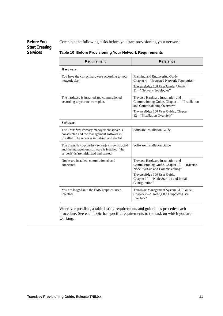
Before You Start Creating Services
Complete the following tasks before you start provisioning your network.
Wherever possible, a table listing requirements and guidelines precedes each procedure. See each topic for specific requirements to the task on which you are working.
Table 10 Before Provisioning Your Network Requirements
Requirement Reference
Hardware
You have the correct hardware according to your network plan.
Planning and Engineering Guide, Chapter 4—“Protected Network Topologies”
TraverseEdge 100 User Guide, Chapter 11—“Network Topologies”
The hardware is installed and commissioned according to your network plan.
Traverse Hardware Installation and Commissioning Guide, Chapter 1—“Installation and Commissioning Overview”
TraverseEdge 100 User Guide,, Chapter 12—“Installation Overview”
Software
The TransNav Primary management server is constructed and the management software is installed. The server is initialized and started.
Software Installation Guide
The TransNav Secondary server(s) is constructed and the management software is installed. The server(s) is/are initialized and started.
Software Installation Guide
Nodes are installed, commissioned, and connected.
Traverse Hardware Installation and Commissioning Guide, Chapter 13—“Traverse Node Start-up and Commissioning”
TraverseEdge 100 User Guide, Chapter 10—“Node Start-up and Initial Configuration”
You are logged into the EMS graphical user interface.
TransNav Management System GUI Guide, Chapter 2—“Starting the Graphical User Interface”
TransNav Provisioning Guide, Release TN5.0.x 11

12 TransNav Provisioning Guide, Release TN5.0.x
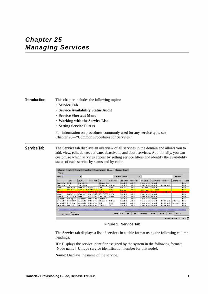
Chapter 25 Managing Services
Introduction This chapter includes the following topics:• Service Tab• Service Availability Status Audit• Service Shortcut Menu• Working with the Service List• Setting Service Filters
For information on procedures commonly used for any service type, see Chapter 26—“Common Procedures for Services.”
Service Tab The Service tab displays an overview of all services in the domain and allows you to add, view, edit, delete, activate, deactivate, and abort services. Additionally, you can customize which services appear by setting service filters and identify the availability status of each service by status and by color.
Figure 1 Service Tab
The Service tab displays a list of services in a table format using the following column headings.
ID: Displays the service identifier assigned by the system in the following format: [Node name] [Unique service identification number for that node].
Name: Displays the name of the service.
TransNav Provisioning Guide, Release TN5.0.x 1
Source, Destination: Displays the source or destination service endpoint in one of the following formats:
Format 1:NodeID/slot#Example: Node1/s-11
Format 2: NodeID/slot#/port#(portType)Example: Node1/s-11/p-1 Example: Node1/s-11/eos-1 Example: Node1/s-11/eop-1
Format 3:NodeID/slot#/port#/sts#Example: Node1/s-11 /p-1/sts-1
Format 4:NodeID/slot#/port#/sts#/vtg#/vt#Example: Node1/s-11 /p-1/sts-1/vtg-1/vt-1
For SONET-STS services with an Ethernet card as the source, the port number is zero (p0). This port refers to the virtual OC-48 interface on the backplane.
Type: Displays the type of service.• DS1: At least one DS1 port is an endpoint for the service.• DS1-Mux: One DS1 card is an endpoint for the service. The DS1 card is mapped into
VT.• DS1-Mux-DS3: One DS1 card is an endpoint for the service. The DS1 card is
multiplexed into DS3.• DS3-CC: One DS3CC port is an endpoint for the service.• DS3-Tmx: One DS3TMX port is an endpoint for the service.• E1: One E1 port is an endpoint for the service.• E1-Mux: One E1 card is an endpoint for the service.• E3-CC: One E3-CC card endpoint for the service.• Ethernet: Is one of the supported Ethernet service types.• SDH-VC11: One of the endpoints is an STM port.• SDH-VC12: One of the endpoints is an STM port.• SDH-VC3: One of the endpoints is an STM port.• SDH-VC3-Endpoint: One of the endpoints is an STM port.• SDH-VC3-Tunnel: One of the VC3 tunnel endpoints is an STM port.• SDH-VC4: One of the endpoints is an STM port.• SDH-VC4-Endpoint: One of the endpoints is an STM port.• SDH-VC4-Tunnel: One of the VC4 tunnel endpoints is an STM port.• SONET-STS: One of the endpoints is an OC or EC1 port.• SONET-Tunnel: One of the SONET tunnel endpoints is an OC port.• SONET-VT1.5: One of the endpoints is an OC port.
2 TransNav Provisioning Guide, Release TN5.0.x
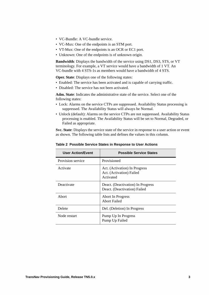
• VC-Bundle: A VC-bundle service.• VC-Mux: One of the endpoints is an STM port.• VT-Mux: One of the endpoints is an OCR or EC1 port.• Unknown: One of the endpoints is of unknown origin.
Bandwidth: Displays the bandwidth of the service using DS1, DS3, STS, or VT terminology. For example, a VT service would have a bandwidth of 1 VT. An VC-bundle with 4 STS-1s as members would have a bandwidth of 4 STS.
Oper. State: Displays one of the following states:• Enabled: The service has been activated and is capable of carrying traffic.• Disabled: The service has not been activated.
Adm. State: Indicates the administrative state of the service. Select one of the following states:• Lock: Alarms on the service CTPs are suppressed. Availability Status processing is
suppressed. The Availability Status will always be Normal. • Unlock (default): Alarms on the service CTPs are not suppressed. Availability Status
processing is enabled. The Availability Status will be set to Normal, Degraded, or Failed as appropriate.
Svc. State: Displays the service state of the service in response to a user action or event as shown. The following table lists and defines the values in this column.
Table 2 Possible Service States in Response to User Actions
User Action/Event Possible Service States
Provision service Provisioned
Activate Act. (Activation) In ProgressAct. (Activation) FailedActivated
Deactivate Deact. (Deactivation) In ProgressDeact. (Deactivation) Failed
Abort Abort In ProgressAbort Failed
Delete Del. (Deletion) In Progress
Node restart Pump Up In ProgressPump Up Failed
TransNav Provisioning Guide, Release TN5.0.x 3

Avail. Status (server GUI and server CLI only): Displays the failure status of services based on ITU-T X.731. Values are normal, degraded, and failed. Each value is color-coded as indicated:
normal: white backgrounddegraded: yellow backgroundfailed: red background
Note: Currently, the values of failed and degraded only display for services with all endpoints along the service path in this release (TR3.2.3) and only for the following services and service types:
– hop-by-hop services – end-to-end services– all Ethernet service types – the following SONET service types: DS1, DS1-MUX, DS3-CC, DS3-TMX,
VT1.5, and STSServices with endpoints on nodes with previous Traverse software releases will always have an Availability Status value of normal.
Note: If the ServiceAlarmMgmtEnabled parameter for the server is disabled, the Availability Status of every service will always remain set to normal, even if service-affecting alarms are raised along the path of the service. For more information on configuring the server parameters, see the Software Installation Guide, Chapter 2—“Management Server Administration.”
For information on how the Alarm status (locked or unlocked) affects the availability status, see the description for Adm State above.For SONET and SDH protected services: – the degraded availability status indicates one or more SA alarms exist on
either of the services’ endpoints on the protection path. – the failed availability status indicates one or more service affecting (SA)
alarms exist on either of the services’ endpoints on the active working path. For Ethernet services: – the failed availability status displays on the service. The status indicates one or
more service affecting (SA) alarms exist on equipment supporting the service.– The degraded availability status displays on a service to indicate one or more
service affecting (SA) alarms exist:- on a service’s Ethernet port endpoint when the Ethernet port is not part of a
LAG - on the service’s LAG port endpoint, EOS port, or EOP port
Customer: Displays the customer name.
Description: Displays the description of the service.
Command buttons are as follows:
Options: Set filters for services to be displayed. Displays the Service List Filters screen. See Setting Service Filters.
Add: Select to add a service. Displays the General Information screen.
4 TransNav Provisioning Guide, Release TN5.0.x

Edit: Select to edit the selected service.
Delete: Select to delete the selected service from the system.
TransNav Provisioning Guide, Release TN5.0.x 5
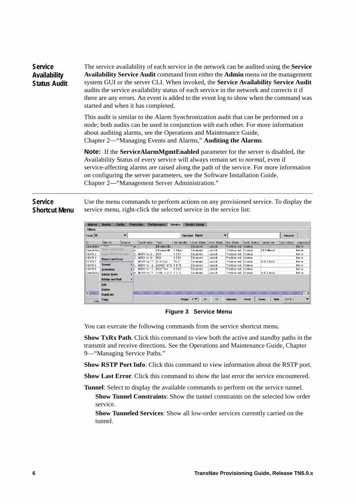
Service Availability Status Audit
The service availability of each service in the network can be audited using the Service Availability Service Audit command from either the Admin menu on the management system GUI or the server CLI. When invoked, the Service Availability Service Audit audits the service availability status of each service in the network and corrects it if there are any errors. An event is added to the event log to show when the command was started and when it has completed.
This audit is similar to the Alarm Synchronization audit that can be performed on a node; both audits can be used in conjunction with each other. For more information about auditing alarms, see the Operations and Maintenance Guide, Chapter 2—“Managing Events and Alarms,” Auditing the Alarms.
Note: If the ServiceAlarmMgmtEnabled parameter for the server is disabled, the Availability Status of every service will always remain set to normal, even if service-affecting alarms are raised along the path of the service. For more information on configuring the server parameters, see the Software Installation Guide, Chapter 2—“Management Server Administration.”
Service Shortcut Menu
Use the menu commands to perform actions on any provisioned service. To display the service menu, right-click the selected service in the service list:
Figure 3 Service Menu
You can execute the following commands from the service shortcut menu.
Show TxRx Path. Click this command to view both the active and standby paths in the transmit and receive directions. See the Operations and Maintenance Guide, Chapter 9—“Managing Service Paths.”
Show RSTP Port Info: Click this command to view information about the RSTP port.
Show Last Error. Click this command to show the last error the service encountered.
Tunnel: Select to display the available commands to perform on the service tunnel.Show Tunnel Constraints: Show the tunnel constraints on the selected low order service. Show Tunneled Services: Show all low-order services currently carried on the tunnel.
6 TransNav Provisioning Guide, Release TN5.0.x

Activation: Select to display the available commands to perform on the service. Activate: Activate the selected service to start carrying traffic. Deactivate: Stop the selected service from carrying traffic.Abort: Abort in-progress service activation, deactivation, or deletion.
Admin State: Select to change the administrative state of the service.Lock: Suppress service CTP alarms and availability status processing.Unlock: Enable service CTP alarms and availability status processing.
Bridge and Roll: Select the command to perform on the service. Roll: Transfer traffic from one facility to another without interrupting service. Create all the bridge services individually first, then roll and commit multiple services. See Chapter 32—“Bridging and Rolling Services”for detailed procedures on bridging and rolling services.Unroll: Allows you to undo the previous command. Commit Rolled: After you roll traffic to a new facility, commit the transfer and delete the original service.
Edit: Edit the selected service.
Delete: Delete the selected service.
Duplicate: Duplicate the service.
Copy: Copy the selected service
Working with the Service List
You can change the way you see the services in the services list.
Sorting Services. Click a column heading to sort the services list by that category. Column headings can be sorted in ascending or descending order. Click the column heading again to switch from ascending to descending order. Hold down the Shift key and click a second column heading to sort the second category within the first category. Hold down the Shift key and click the second column again to switch between ascending and descending order within the first category.
Resizing Columns. To change the width of a column, drag the mouse between column headings, e.g., between Name and Egress, until you see a double arrow. Click and drag to the left or right to change the column width.
Grouping Services. Select a service listed on the Service tab. Hold the Ctrl key down to select a range of services. Hold the Shift key down, then click specific services to select them. You can now activate, deactivate, or delete the selected group of services.
Filtering Services. Sort and view the services using the Options button. See Setting Service Filters.
TransNav Provisioning Guide, Release TN5.0.x 7
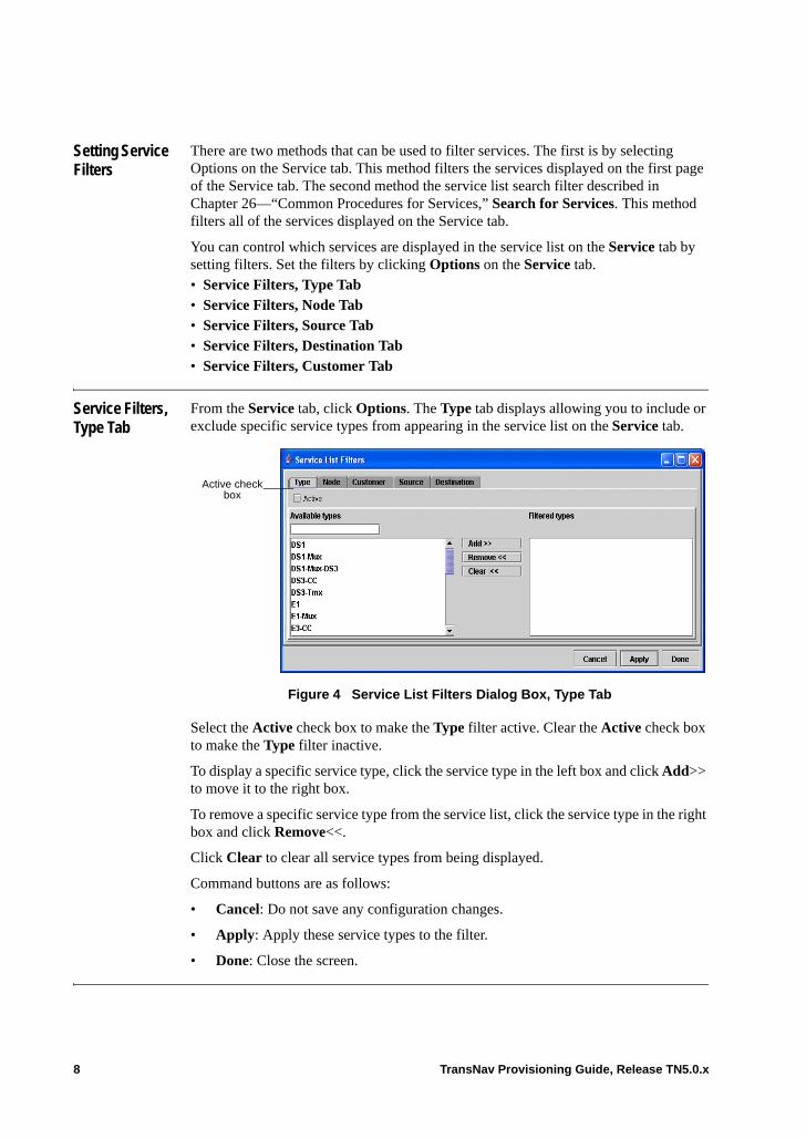
Setting Service Filters
There are two methods that can be used to filter services. The first is by selecting Options on the Service tab. This method filters the services displayed on the first page of the Service tab. The second method the service list search filter described in Chapter 26—“Common Procedures for Services,” Search for Services. This method filters all of the services displayed on the Service tab.
You can control which services are displayed in the service list on the Service tab by setting filters. Set the filters by clicking Options on the Service tab.• Service Filters, Type Tab• Service Filters, Node Tab• Service Filters, Source Tab• Service Filters, Destination Tab• Service Filters, Customer Tab
Service Filters, Type Tab
From the Service tab, click Options. The Type tab displays allowing you to include or exclude specific service types from appearing in the service list on the Service tab.
Figure 4 Service List Filters Dialog Box, Type Tab
Select the Active check box to make the Type filter active. Clear the Active check box to make the Type filter inactive.
To display a specific service type, click the service type in the left box and click Add>> to move it to the right box.
To remove a specific service type from the service list, click the service type in the right box and click Remove<<.
Click Clear to clear all service types from being displayed.
Command buttons are as follows:
• Cancel: Do not save any configuration changes.
• Apply: Apply these service types to the filter.
• Done: Close the screen.
Active check box
8 TransNav Provisioning Guide, Release TN5.0.x
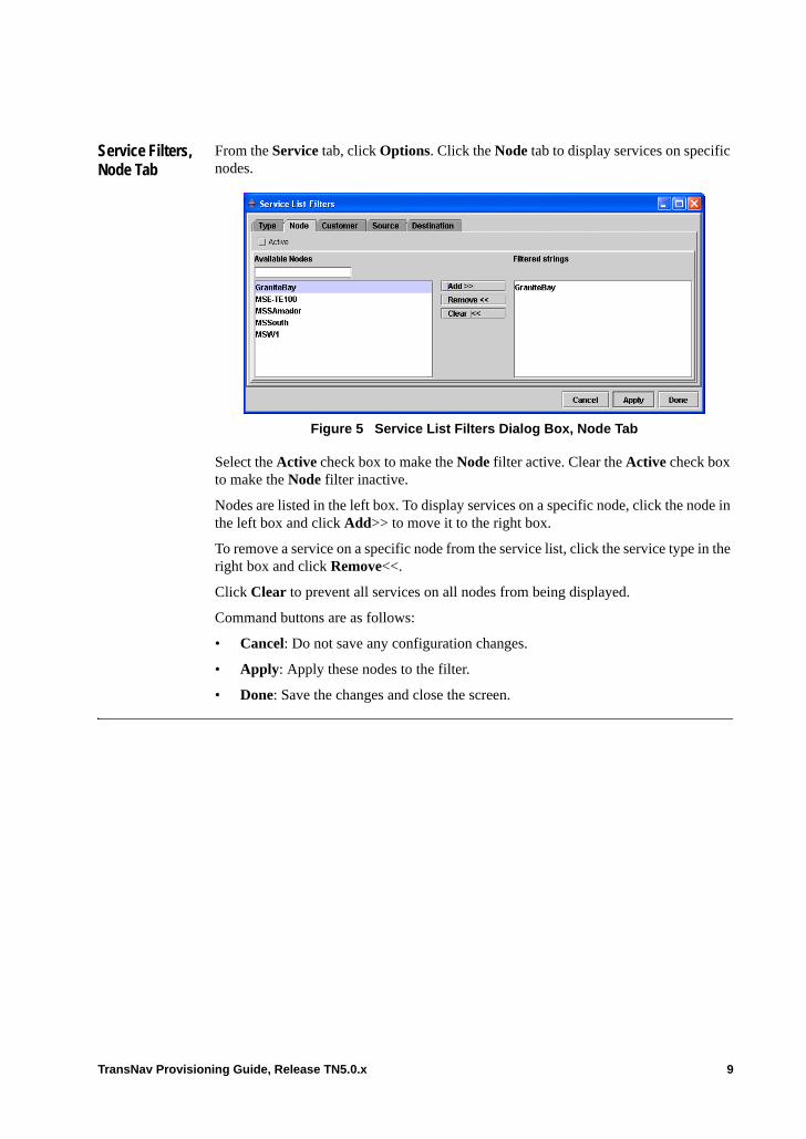
Service Filters, Node Tab
From the Service tab, click Options. Click the Node tab to display services on specific nodes.
Figure 5 Service List Filters Dialog Box, Node Tab
Select the Active check box to make the Node filter active. Clear the Active check box to make the Node filter inactive.
Nodes are listed in the left box. To display services on a specific node, click the node in the left box and click Add>> to move it to the right box.
To remove a service on a specific node from the service list, click the service type in the right box and click Remove<<.
Click Clear to prevent all services on all nodes from being displayed.
Command buttons are as follows:
• Cancel: Do not save any configuration changes.
• Apply: Apply these nodes to the filter.
• Done: Save the changes and close the screen.
TransNav Provisioning Guide, Release TN5.0.x 9
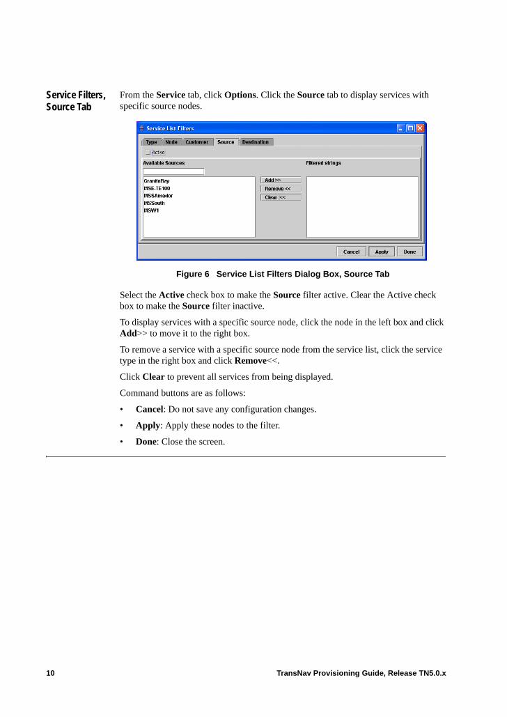
Service Filters, Source Tab
From the Service tab, click Options. Click the Source tab to display services with specific source nodes.
Figure 6 Service List Filters Dialog Box, Source Tab
Select the Active check box to make the Source filter active. Clear the Active check box to make the Source filter inactive.
To display services with a specific source node, click the node in the left box and click Add>> to move it to the right box.
To remove a service with a specific source node from the service list, click the service type in the right box and click Remove<<.
Click Clear to prevent all services from being displayed.
Command buttons are as follows:
• Cancel: Do not save any configuration changes.
• Apply: Apply these nodes to the filter.
• Done: Close the screen.
10 TransNav Provisioning Guide, Release TN5.0.x
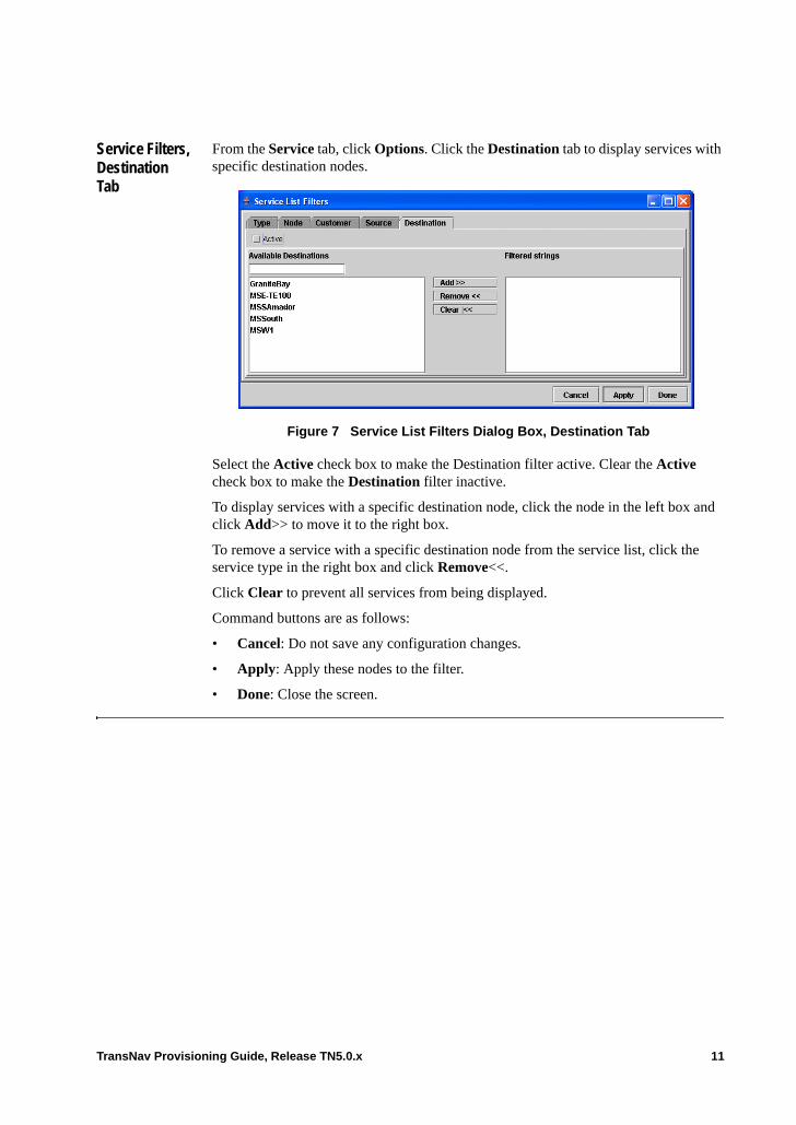
Service Filters, Destination Tab
From the Service tab, click Options. Click the Destination tab to display services with specific destination nodes.
Figure 7 Service List Filters Dialog Box, Destination Tab
Select the Active check box to make the Destination filter active. Clear the Active check box to make the Destination filter inactive.
To display services with a specific destination node, click the node in the left box and click Add>> to move it to the right box.
To remove a service with a specific destination node from the service list, click the service type in the right box and click Remove<<.
Click Clear to prevent all services from being displayed.
Command buttons are as follows:
• Cancel: Do not save any configuration changes.
• Apply: Apply these nodes to the filter.
• Done: Close the screen.
TransNav Provisioning Guide, Release TN5.0.x 11
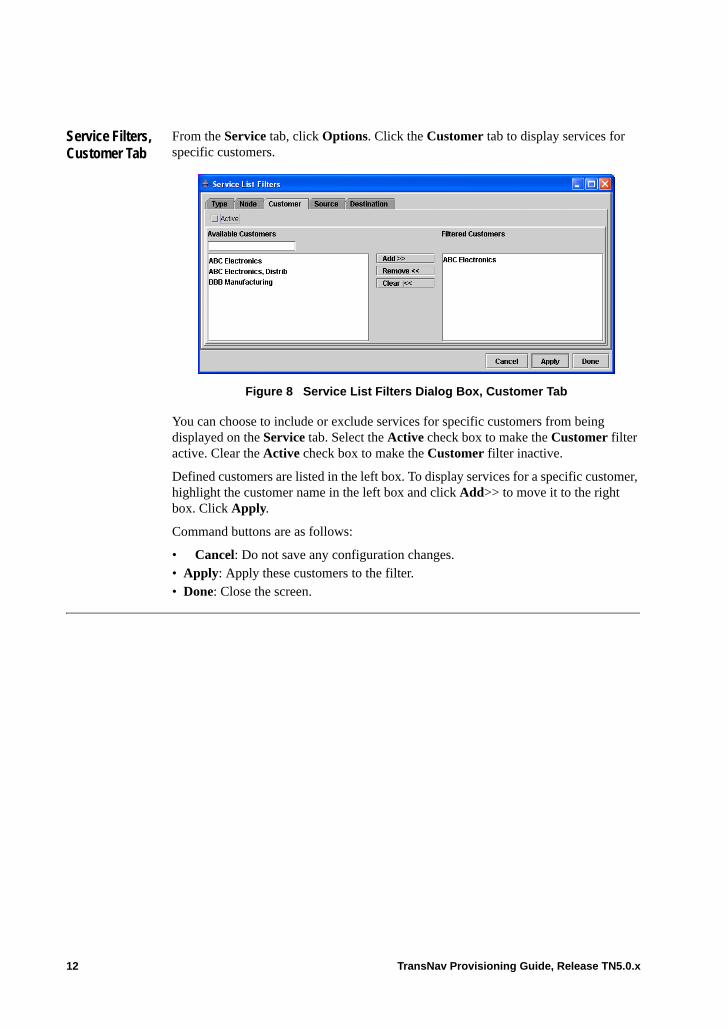
Service Filters, Customer Tab
From the Service tab, click Options. Click the Customer tab to display services for specific customers.
Figure 8 Service List Filters Dialog Box, Customer Tab
You can choose to include or exclude services for specific customers from being displayed on the Service tab. Select the Active check box to make the Customer filter active. Clear the Active check box to make the Customer filter inactive.
Defined customers are listed in the left box. To display services for a specific customer, highlight the customer name in the left box and click Add>> to move it to the right box. Click Apply.
Command buttons are as follows:
• Cancel: Do not save any configuration changes.• Apply: Apply these customers to the filter.• Done: Close the screen.
12 TransNav Provisioning Guide, Release TN5.0.x
Chapter 26 Common Procedures for Services
Introduction This chapter contains procedures for the following topics:• For Strict Services, Configure the Path Through the Network• Activate or Deactivate a Service• Duplicate a Service• Search for Services• Choose an Endpoint• Configure Advanced Parameters (Alphabetic Order)
TransNav Provisioning Guide, Release TN5.0.x 1
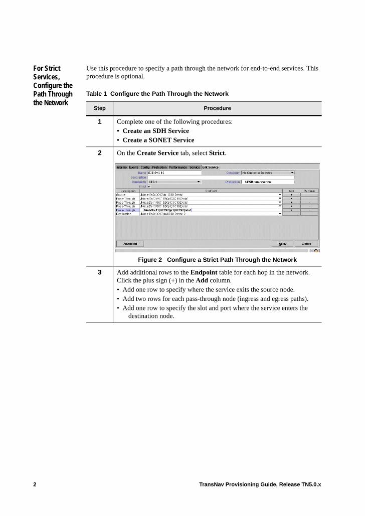
For Strict Services, Configure the Path Through the Network
Use this procedure to specify a path through the network for end-to-end services. This procedure is optional.
Table 1 Configure the Path Through the Network
Step Procedure
1 Complete one of the following procedures: • Create an SDH Service• Create a SONET Service
2 On the Create Service tab, select Strict.
Figure 2 Configure a Strict Path Through the Network
3 Add additional rows to the Endpoint table for each hop in the network. Click the plus sign (+) in the Add column.• Add one row to specify where the service exits the source node.• Add two rows for each pass-through node (ingress and egress paths).• Add one row to specify the slot and port where the service enters the
destination node.
2 TransNav Provisioning Guide, Release TN5.0.x
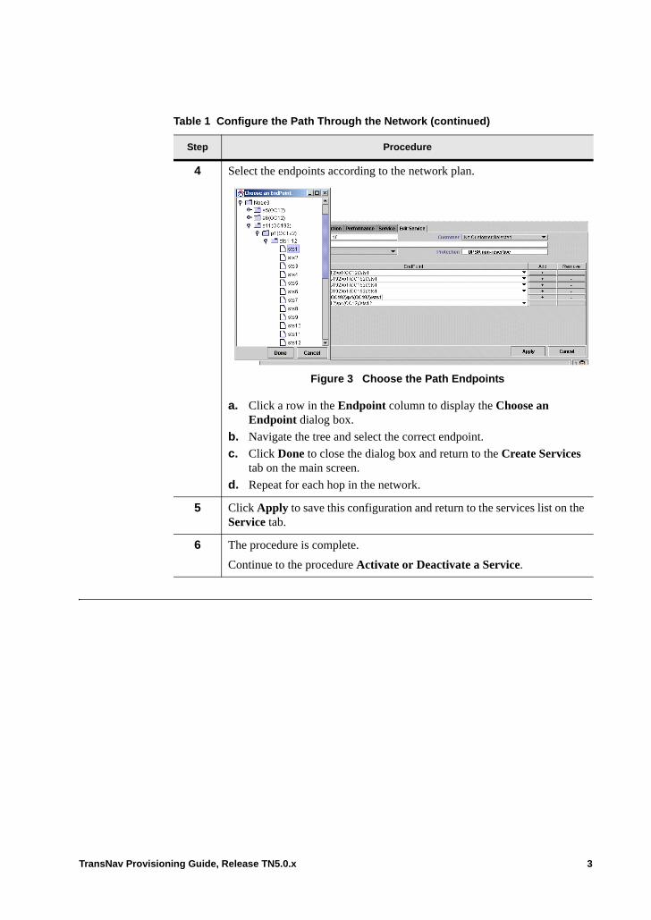
4 Select the endpoints according to the network plan.
Figure 3 Choose the Path Endpoints
a. Click a row in the Endpoint column to display the Choose an Endpoint dialog box.
b. Navigate the tree and select the correct endpoint.
c. Click Done to close the dialog box and return to the Create Services tab on the main screen.
d. Repeat for each hop in the network.
5 Click Apply to save this configuration and return to the services list on the Service tab.
6 The procedure is complete.
Continue to the procedure Activate or Deactivate a Service.
Table 1 Configure the Path Through the Network (continued)
Step Procedure
TransNav Provisioning Guide, Release TN5.0.x 3
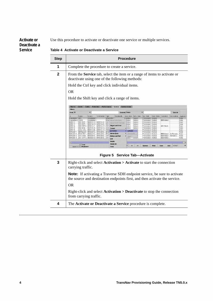
Activate or Deactivate a Service
Use this procedure to activate or deactivate one service or multiple services.
Table 4 Activate or Deactivate a Service
Step Procedure
1 Complete the procedure to create a service.
2 From the Service tab, select the item or a range of items to activate or deactivate using one of the following methods:
Hold the Ctrl key and click individual items.
OR
Hold the Shift key and click a range of items.
Figure 5 Service Tab—Activate
3 Right-click and select Activation > Activate to start the connection carrying traffic.
Note: If activating a Traverse SDH endpoint service, be sure to activate the source and destination endpoints first, and then activate the service.
OR
Right-click and select Activation > Deactivate to stop the connection from carrying traffic.
4 The Activate or Deactivate a Service procedure is complete.
4 TransNav Provisioning Guide, Release TN5.0.x
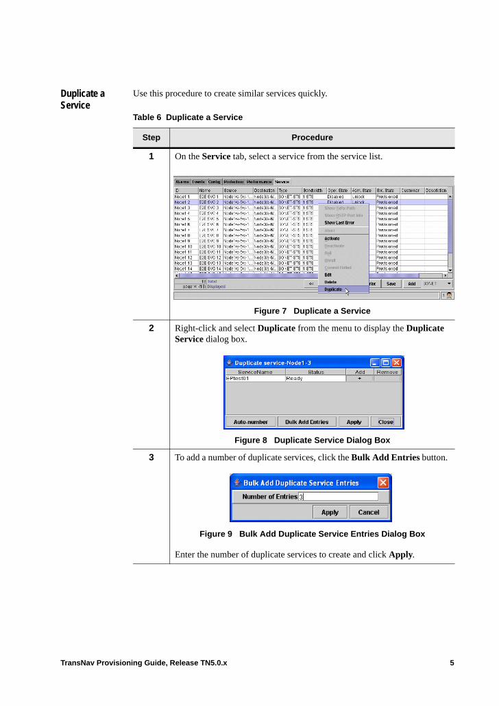
Duplicate a Service
Use this procedure to create similar services quickly.
Table 6 Duplicate a Service
Step Procedure
1 On the Service tab, select a service from the service list.
Figure 7 Duplicate a Service
2 Right-click and select Duplicate from the menu to display the Duplicate Service dialog box.
Figure 8 Duplicate Service Dialog Box
3 To add a number of duplicate services, click the Bulk Add Entries button.
Figure 9 Bulk Add Duplicate Service Entries Dialog Box
Enter the number of duplicate services to create and click Apply.
TransNav Provisioning Guide, Release TN5.0.x 5
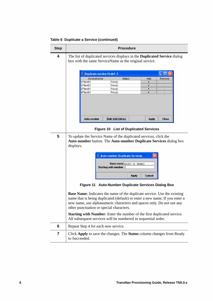
4 The list of duplicated services displays in the Duplicated Service dialog box with the same ServiceName as the original service.
Figure 10 List of Duplicated Services
5 To update the Service Name of the duplicated services, click the Auto-number button. The Auto-number Duplicate Services dialog box displays.
Figure 11 Auto-Number Duplicate Services Dialog Box
Base Name: Indicates the name of the duplicate service. Use the existing name that is being duplicated (default) or enter a new name. If you enter a new name, use alphanumeric characters and spaces only. Do not use any other punctuation or special characters.
Starting with Number: Enter the number of the first duplicated service. All subsequent services will be numbered in sequential order.
6 Repeat Step 4 for each new service.
7 Click Apply to save the changes. The Status column changes from Ready to Succeeded.
Table 6 Duplicate a Service (continued)
Step Procedure
6 TransNav Provisioning Guide, Release TN5.0.x
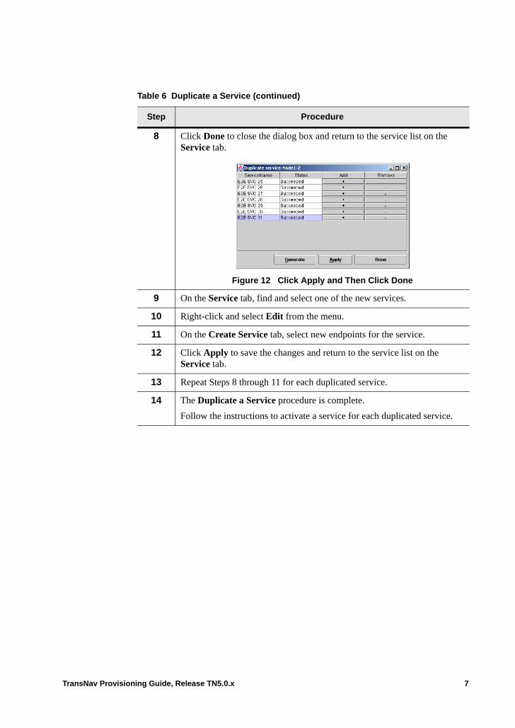
8 Click Done to close the dialog box and return to the service list on the Service tab.
Figure 12 Click Apply and Then Click Done
9 On the Service tab, find and select one of the new services.
10 Right-click and select Edit from the menu.
11 On the Create Service tab, select new endpoints for the service.
12 Click Apply to save the changes and return to the service list on the Service tab.
13 Repeat Steps 8 through 11 for each duplicated service.
14 The Duplicate a Service procedure is complete.
Follow the instructions to activate a service for each duplicated service.
Table 6 Duplicate a Service (continued)
Step Procedure
TransNav Provisioning Guide, Release TN5.0.x 7

Search for Services
Use the following procedure to search for specific services in the Traverse system.
Note: The use of wildcards (*) in the search filters is important to narrow the range of returned search values that include alphanumeric descriptions. For example, a wildcard search on *c*r* returns search results that include car, card, and accord.
Table 13 Search for Services
Step Procedure
1 Review the information in the topic Before You Begin.
2 From Map View or Shelf View, click the Service tab.
Figure 14 Select the Service Tab
3 Select the type of filter to be used as the first priority in the search and enter the appropriate search text (i.e., service identifier number, service name, etc.). The text is case-sensitive. Wildcards can be used where indicated for the following values.• ID: The alphanumeric service identifier assigned by the system in the
following format. Use wildcards (*) to search for specific identifiers. <Node name> <Unique service identification number for that node>
• Name: The alphanumeric name of the service. Use wildcards (*) to search for specific service names.
• Source: The alphanumeric source service endpoint in the following format. Use wildcards (*) to narrow your search for specific endpoints. NodeID / slot<Number><cardType> / port<Number><portType> / sts<Number>/ vtg<Number> / vt<Number>
For SONET-STS services with an Ethernet card as the source the port number is zero (p0). This refers to the OC-48 interface on the backplane.
8 TransNav Provisioning Guide, Release TN5.0.x
• Destination: The alphanumeric destination service endpoint in the following format. Use wildcards (*) to narrow your search for specific destination endpoints. NodeID / slot<Number><cardType> / port<Number><portType> / sts<Number> / vtg<Number> / vt<Number>
• Type: Select the type of service.• Operation State: The operative state of the service. Enabled indicates
the service is activated and is capable of carrying traffic. Disabled indicates the service is not activated.
• Admin State: The administrative state of the service. Valid values are Locked (the service is not activated to carry traffic) or Unlocked (the service is activated to carry traffic).
• Service State: The service state of the service. Valid values are:– Provision service– Activate– Deactivate– Abort– Delete– Node restart
• Availability Status: Indicates the failure status of the service as defined in ITU-T X.731. Valid values are Normal, Degraded, and Failed. The default is Normal.
Note: Only services created on nodes running Release TR3.2.3 or later will display as Degraded or Failed.
• Customer: The alphanumeric customer name. Use wildcards (*) to narrow your search for specific customers.
• Description: The alphanumeric description of the service. Use wildcards (*) to narrow your search for specific descriptions.
4 Select the type of filter for the Second search priority. The selected value must be different than the filter type selected in the First field. Enter the appropriate search text (i.e, service identifier number, service name, etc.). The text is case-sensitive.
Table 13 Search for Services (continued)
Step Procedure
TransNav Provisioning Guide, Release TN5.0.x 9
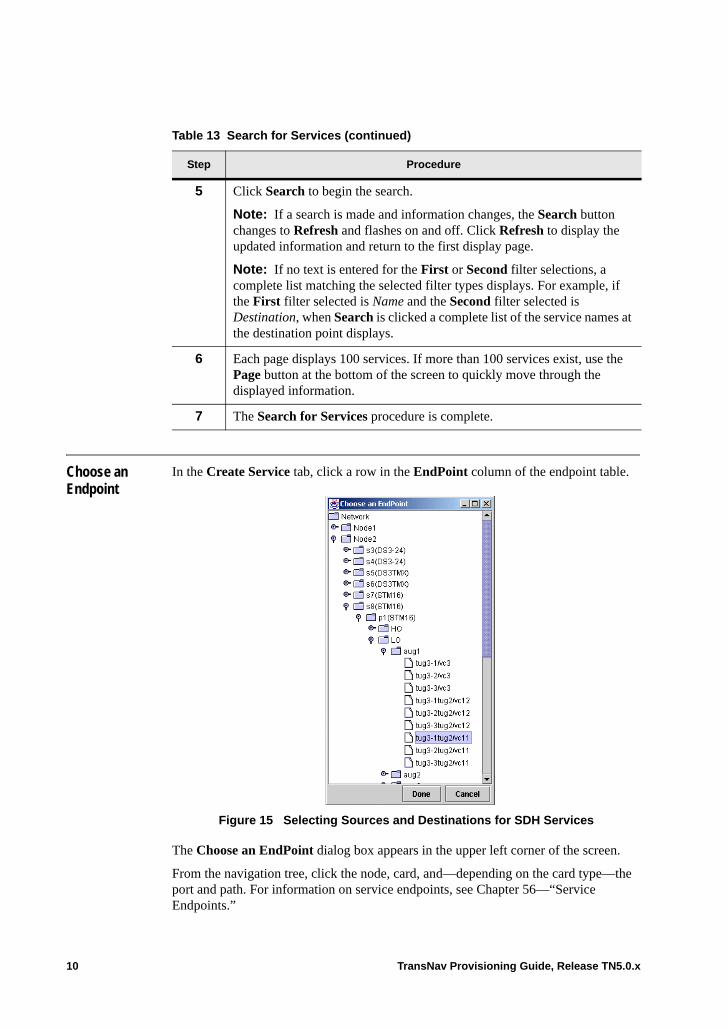
Choose an Endpoint
In the Create Service tab, click a row in the EndPoint column of the endpoint table.
Figure 15 Selecting Sources and Destinations for SDH Services
The Choose an EndPoint dialog box appears in the upper left corner of the screen.
From the navigation tree, click the node, card, and—depending on the card type—the port and path. For information on service endpoints, see Chapter 56—“Service Endpoints.”
5 Click Search to begin the search.
Note: If a search is made and information changes, the Search button changes to Refresh and flashes on and off. Click Refresh to display the updated information and return to the first display page.
Note: If no text is entered for the First or Second filter selections, a complete list matching the selected filter types displays. For example, if the First filter selected is Name and the Second filter selected is Destination, when Search is clicked a complete list of the service names at the destination point displays.
6 Each page displays 100 services. If more than 100 services exist, use the Page button at the bottom of the screen to quickly move through the displayed information.
7 The Search for Services procedure is complete.
Table 13 Search for Services (continued)
Step Procedure
10 TransNav Provisioning Guide, Release TN5.0.x
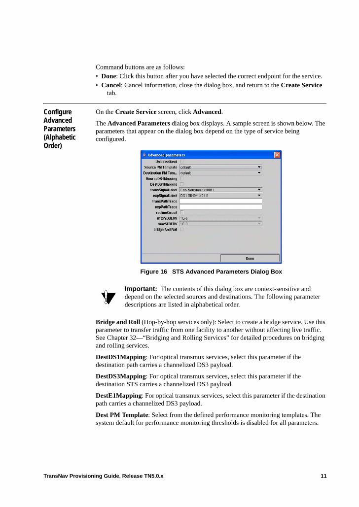
Command buttons are as follows:• Done: Click this button after you have selected the correct endpoint for the service.• Cancel: Cancel information, close the dialog box, and return to the Create Service
tab.
Configure Advanced Parameters (Alphabetic Order)
On the Create Service screen, click Advanced.
The Advanced Parameters dialog box displays. A sample screen is shown below. The parameters that appear on the dialog box depend on the type of service being configured.
.
Figure 16 STS Advanced Parameters Dialog Box
Bridge and Roll (Hop-by-hop services only): Select to create a bridge service. Use this parameter to transfer traffic from one facility to another without affecting live traffic. See Chapter 32—“Bridging and Rolling Services” for detailed procedures on bridging and rolling services.
DestDS1Mapping: For optical transmux services, select this parameter if the destination path carries a channelized DS3 payload.
DestDS3Mapping: For optical transmux services, select this parameter if the destination STS carries a channelized DS3 payload.
DestE1Mapping: For optical transmux services, select this parameter if the destination path carries a channelized DS3 payload.
Dest PM Template: Select from the defined performance monitoring templates. The system default for performance monitoring thresholds is disabled for all parameters.
Important: The contents of this dialog box are context-sensitive and depend on the selected sources and destinations. The following parameter descriptions are listed in alphabetical order.
TransNav Provisioning Guide, Release TN5.0.x 11
Use the performance monitoring templates to set default thresholds or to customize threshold values. See the Operations and Maintenance Guide, Chapter 4—“Managing Performance” for information on how to use performance monitoring templates.
Expected RTD (TE-100 only): Enter the expected round trip delay measurement, in milliseconds, for this service. Values are 0 to 1000 milliseconds; default is 300ms.
Failure Retry Count (end-to-end services only): The number of times the system tries to reestablish the service before declaring it failed. Select 0 to 30; default is 3.
Fwd Path Format: This port transmits a path trace identifier in the J1 byte of the SONET/SDH frame so that the path receiver can verify its continued connection. The values are:• 16 bytes (default): Select if the receiver is an SDH port.• 64 bytes: Select if the receiver is another SONET port.
Fwd Path Trace: The path trace identifier transmitted in the J1 byte. Enter an alphanumeric character string.
Fwd Signal Label: The path signal label (C2 byte in the STS path overhead) in the forward direction of the LSP. Select one of the following options:• Unequipped(00)• Eqp-Nonspecific(01) (default): Equipped - Nonspecific Payload• VT-Structured(02): VT-structured STS-1 SPE• Locked VT(03): Locked virtual tributary (VT) mode• DS3 Async(04): Asynchronous mapping for E3 or DS3. • DS4NA Async(12): Asynchronous mapping for DS4NA or E4. • ATM Map(13): Mapping for ATM• DQDB Map(14): Mapping for DQDB• FDDI Async(15): Asynchronous mapping for FDDI• HDLC-PPP(16): HDLC-Over-SONET mapping• X.86(18)• GFB (1B): Generic Framing Procedure Frame format (ITU-T G.7041)• POS No-Scramble (CF)• Test Signal (FE): O.181 Test Signal (TSS1 to TSS3) mapping
Load Balance Most-Fill (read-only): If there are two paths of equal cost and Link1 and Link2 are the first different links between the paths, Most-Fill will use the link that is most filled between the two links. This reduces bandwidth fragmentation among links.
Max Hop Count (end-to-end services only): Displays the maximum number of hops to the timing source.
Max SD-BER-V: Maximum signal degrade bit error rate for VT path. Measures the transmission quality (bit error ratio) of degraded signals in the VT path. When the error rate crosses the value specified in this parameter, the system raises a signal degraded bit error rate (BERSD-V) alarm. Select one of the following values:
– 1E-4: Value equals 1 x 10⁻⁴
– 1E-5: Value equals 1 x 10⁻⁵
– 1E-6 (default): Value equals 1 x 10⁻⁶
12 TransNav Provisioning Guide, Release TN5.0.x
– 1E-7: Value equals 1 x 10⁻⁷
– 1E-8: Value equals 1 x 10⁻⁸
– 1E-9: Value equals 1 x 10⁻⁹
Max SF-BER-V: Measures the transmission quality (bit error ratio) of failed signals in the VT path. When the error rate crosses the value specified in this parameter, the system raises a signal failed bit error rate (BERSF-V) alarm. Select one of the following values:
– 1E-3 (default): Value equals 1 x 10⁻³
– 1E-4: Value equals 1 x 10⁻⁴
– 1E-5: Value equals 1 x 10⁻⁵
Monitor RTD: Select to enable the delay measurement function for this service; default is disable (cleared checkbox).
Path Mapping: Maps the VC-3 payload onto a transport path. This parameter determines how to monitor alarms and performance of the service through the intermediate nodes in the network. • STS: Maps the payload into an STS path• AU-4/LOVC (default): Maps the payload into an AU-4 low order virtual container• AU-3/HOVC: Maps the payload into an AU-3 high order path virtual container
Payload Mapping: Maps the STS-1 or VC-3 payload as a clear-channel container with no VT or VC containers. The clear-channel container is capable of processing low order containers. When either endpoint is a card capable of processing low-order containers, all containers within the STS-1 or VC-3 will be available on that card as individual low-order CTPs.
Redline Circuit (Traverse) / VCRedline Circuit (TE-100): Use this attribute to mark a service with “Do not Deactivate.” A redline circuit prevents accidental deactivation of an important service. You must first reset the redline attribute, then deactivate the service. Select one of the following options:• Yes: Service is a redline circuit and cannot be deactivated• No (default): Service is not a redline circuit and can be deactivated
Rev Path Format: This port receives a path trace identifier in the J1 byte of the SONET/SDH frame so that the path transmitter can verify its continued connection. Select one of the following options:• 16 bytes (default): Select if the receiver is an SDH port • 64 bytes: Select if the receiver is another SONET port
Rev Path Trace: The expected path trace identifier transmitted in the J1 byte. Enter an alphanumeric character string. Not used for unidirectional connections.
Rev Signal Label: The path signal label (C2 byte in the STS path overhead) in the reverse direction of the LSP. Not used for unidirectional connections. Select one of the following values:• Unequipped(00)• Eqp-Nonspecific(01) (default): Equipped - Nonspecific Payload• VT-Structured(02): VT-structured STS-1 SPE• Locked VT(03): Locked virtual tributary (VT) mode
TransNav Provisioning Guide, Release TN5.0.x 13
• DS3 Async(04): Asynchronous mapping for DS3• DS4NA Async(12): Asynchronous mapping for DS4NA• ATM Map(13): Mapping for ATM• DQDB Map(14): Mapping for DQDB• FDDI Async(15): Asynchronous mapping for FDDI• HDLC-PPP(16): HDLC-Over-SONET mapping• X.86(18)• GFB (1B)• POS No-Scramble (CF)• Test Signal (FE): O.181 Test Signal (TSS1 to TSS3) mapping
Setup Retry Count (end-to-end services only): The number of times the system retries a service activation request before declaring that activation failed. Select 0 to 30; default is 3.
SourceDS1Mapping: For optical transmux services, select this parameter if the source path carries a channelized DS3 payload.
SourceDS3Mapping: For optical transmux services, select this parameter if the source STS carries a channelized DS3 payload.
SourceE1Mapping: For optical transmux services, select this parameter if the source path carries a channelized DS3 payload.
Source PM Template: Select from the defined performance monitoring templates. The system default for performance monitoring thresholds is disabled for all parameters.
Use the performance monitoring templates to set default thresholds or to customize threshold values. See the Operations and Maintenance Guide, Chapter 4—“Managing Performance” for information on how to use performance monitoring templates.
See the Operations and Maintenance Guide for details on performance monitoring parameters for optical ports.
TMX Port: For optical transmux services, select the port you designated as the STS1TMX resource.
Transparency (high bandwidth services only): Specifies if this service is transparently transporting payloads and overhead of legacy equipment. This service must have a STS-12c, STS-48c, VC-4-4c, or VC-4-16c bandwidth. The Control Data parameter must be Disabled on the interface. Select ON or OFF.• On: This service has a bandwidth of STS-48c and is transparently transporting
services between legacy equipment• Off (default): This service is not a transparency service
Unidirectional: Select for a unidirectional connection (the traffic can only travel in one direction—from source to destination).
The default is unselected which means that the connection is bidirectional (traffic travels in both directions). Within a UPSR ring, a path may take one link for forward traffic and another link for backward traffic. For topologies other than UPSR, the forward traffic and backward traffic travel across exactly the same links.
14 TransNav Provisioning Guide, Release TN5.0.x
Chapter 27 Configuring SONET Services
Introduction This chapter explains how to create the following service types in a Traverse network:• SONET-STS: Use this service to transport synchronous traffic through the network.
Use this service to create a transport path for either synchronous or Ethernet traffic through the network.
• SONET-VT1.5: Use this service to switch individual SONET VT1.5 payloads through the network.
Note: VT services are available on all cards except the 10 GbE and GbE-10 cards.
This chapter includes the following topics:• Examples of SONET Services• Cards Required to Create SONET Services• Before You Create SONET Services• Guidelines to Provision a SONET VT-Mux Service• Payload Mapping Parameter• Automatic in Service• Create a SONET Service
If your system includes 2-port OC-48 cards, see Chapter 30—“Creating 2-Port OC-48/STM-16 Services” for additional information.
For information on Low Order end-to-end services, see Chapter 28—“Creating SONET Low Order End-to-End Services and Tunnels.”
TransNav Provisioning Guide, Release TN5.0.x 1
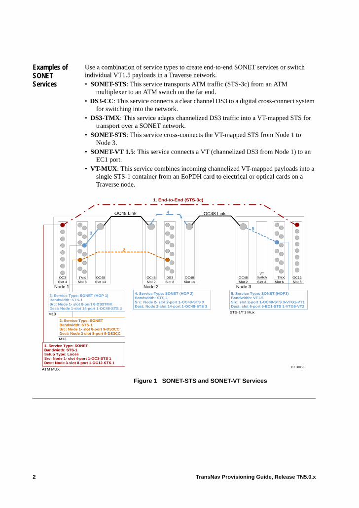
Examples of SONET Services
Use a combination of service types to create end-to-end SONET services or switch individual VT1.5 payloads in a Traverse network.• SONET-STS: This service transports ATM traffic (STS-3c) from an ATM
multiplexer to an ATM switch on the far end.• DS3-CC: This service connects a clear channel DS3 to a digital cross-connect system
for switching into the network.• DS3-TMX: This service adapts channelized DS3 traffic into a VT-mapped STS for
transport over a SONET network.• SONET-STS: This service cross-connects the VT-mapped STS from Node 1 to
Node 3.• SONET-VT 1.5: This service connects a VT (channelized DS3 from Node 1) to an
EC1 port. • VT-MUX: This service combines incoming channelized VT-mapped payloads into a
single STS-1 container from an EoPDH card to electrical or optical cards on a Traverse node.
Figure 1 SONET-STS and SONET-VT Services
Node 1 Node 2 Node 3
OC48 Link OC48 Link
5
OC3 TMXVT
Switch OC12OC48 OC48 OC48 TMXDS3
1. End-to-End (STS-3c)
3
4
2
M13
Slot 2 Slot 3 Slot 6 Slot 8Slot 8Slot 2Slot 14Slot 8Slot 4
ATM MUX
M13
1. Service Type: SONETBandwidth: STS-1Setup Type: LooseSrc: Node 1- slot 4-port 1-OC3-STS 1Dest: Node 3-slot 8-port 1-OC12-STS 1
3. Service Type: SONET (HOP 1)Bandwidth: STS-1Src: Node 1- slot 8-port 6-DS3TMXDest: Node 1-slot 14-port 1-OC48-STS 3
2. Service Type: SONETBandwidth: STS-1Src: Node 1- slot 8-port 9-DS3CCDest: Node 2-slot 8-port 9-DS3CC
4. Service Type: SONET (HOP 2)Bandwidth: STS-1Src: Node 2- slot 2-port 1-OC48-STS 3Dest: Node 2-slot 14-port 1-OC48-STS 3
STS-1/T1 Mux
5. Service Type: SONET (HOP3)Bandwidth: VT1.5Src: slot 2-port 1-OC48-STS 3-VTG1-VT1Dest: slot 6-port 5-EC1-STS 1-VTG5-VT2
OC48Slot 14
TR 00056
2 TransNav Provisioning Guide, Release TN5.0.x
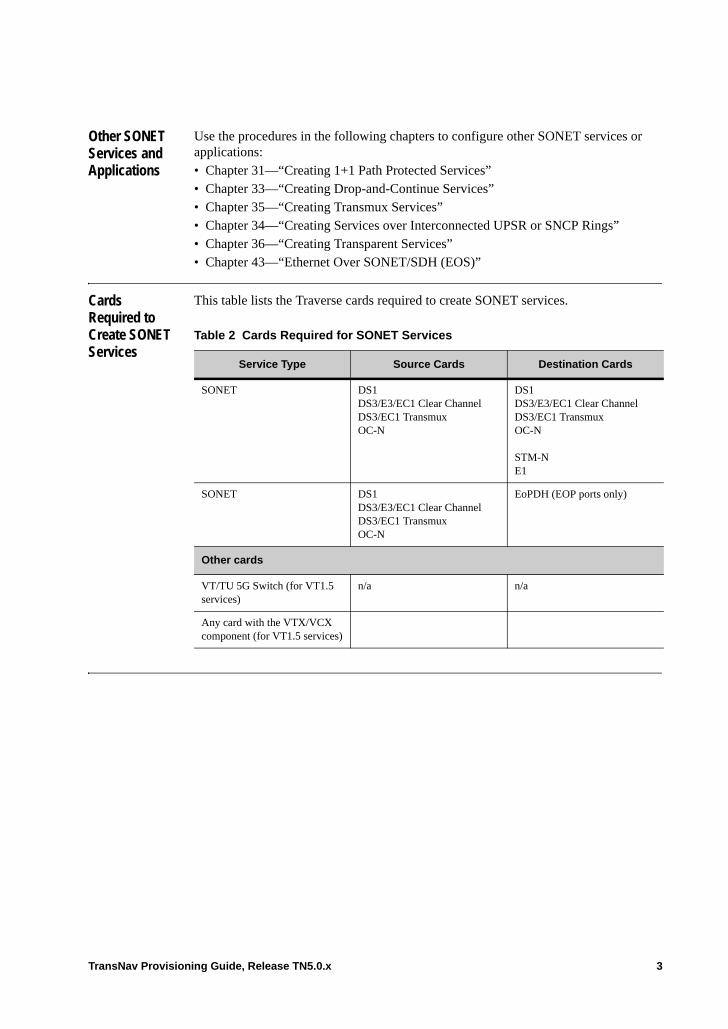
Other SONET Services and Applications
Use the procedures in the following chapters to configure other SONET services or applications: • Chapter 31—“Creating 1+1 Path Protected Services”• Chapter 33—“Creating Drop-and-Continue Services”• Chapter 35—“Creating Transmux Services”• Chapter 34—“Creating Services over Interconnected UPSR or SNCP Rings”• Chapter 36—“Creating Transparent Services”• Chapter 43—“Ethernet Over SONET/SDH (EOS)”
Cards Required to Create SONET Services
This table lists the Traverse cards required to create SONET services.
Table 2 Cards Required for SONET Services
Service Type Source Cards Destination Cards
SONET DS1DS3/E3/EC1 Clear ChannelDS3/EC1 TransmuxOC-N
DS1DS3/E3/EC1 Clear ChannelDS3/EC1 TransmuxOC-N
STM-NE1
SONET DS1DS3/E3/EC1 Clear ChannelDS3/EC1 TransmuxOC-N
EoPDH (EOP ports only)
Other cards
VT/TU 5G Switch (for VT1.5 services)
n/a n/a
Any card with the VTX/VCX component (for VT1.5 services)
TransNav Provisioning Guide, Release TN5.0.x 3
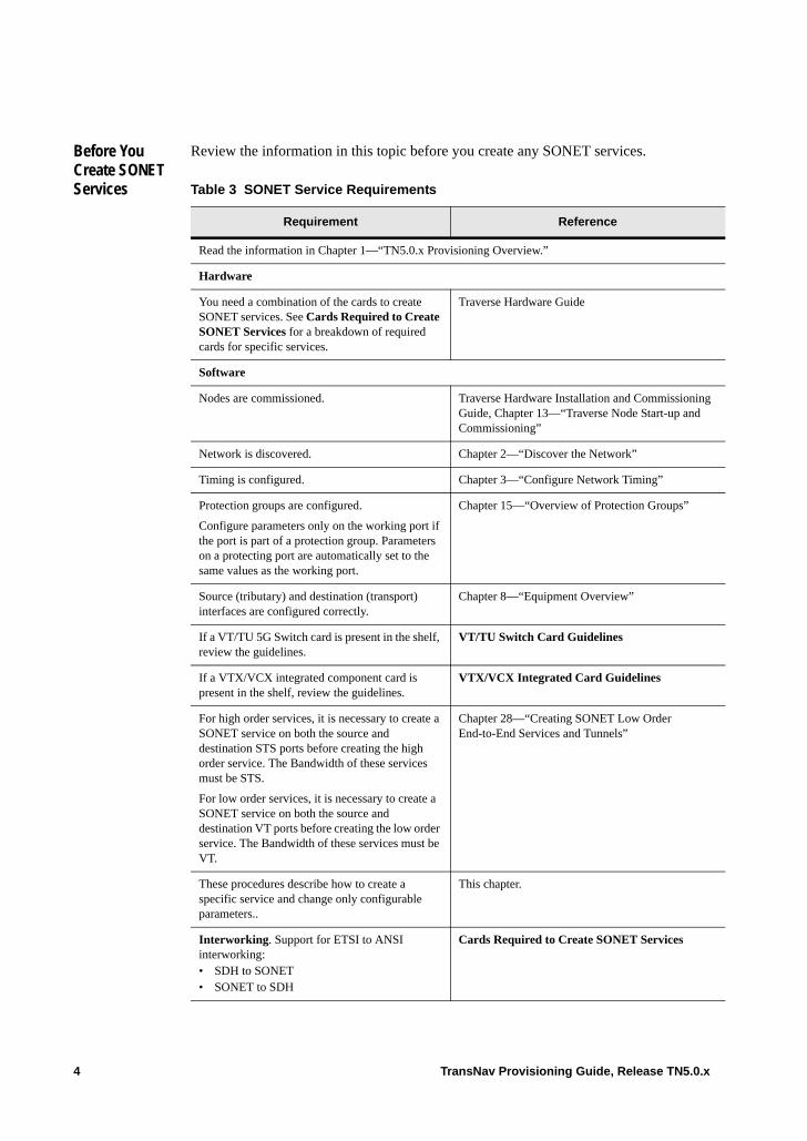
Before You Create SONET Services
Review the information in this topic before you create any SONET services.
Table 3 SONET Service Requirements
Requirement Reference
Read the information in Chapter 1—“TN5.0.x Provisioning Overview.”
Hardware
You need a combination of the cards to create SONET services. See Cards Required to Create SONET Services for a breakdown of required cards for specific services.
Traverse Hardware Guide
Software
Nodes are commissioned. Traverse Hardware Installation and Commissioning Guide, Chapter 13—“Traverse Node Start-up and Commissioning”
Network is discovered. Chapter 2—“Discover the Network”
Timing is configured. Chapter 3—“Configure Network Timing”
Protection groups are configured.
Configure parameters only on the working port if the port is part of a protection group. Parameters on a protecting port are automatically set to the same values as the working port.
Chapter 15—“Overview of Protection Groups”
Source (tributary) and destination (transport) interfaces are configured correctly.
Chapter 8—“Equipment Overview”
If a VT/TU 5G Switch card is present in the shelf, review the guidelines.
VT/TU Switch Card Guidelines
If a VTX/VCX integrated component card is present in the shelf, review the guidelines.
VTX/VCX Integrated Card Guidelines
For high order services, it is necessary to create a SONET service on both the source and destination STS ports before creating the high order service. The Bandwidth of these services must be STS.
For low order services, it is necessary to create a SONET service on both the source and destination VT ports before creating the low order service. The Bandwidth of these services must be VT.
Chapter 28—“Creating SONET Low Order End-to-End Services and Tunnels”
These procedures describe how to create a specific service and change only configurable parameters..
This chapter.
Interworking. Support for ETSI to ANSI interworking:• SDH to SONET• SONET to SDH
Cards Required to Create SONET Services
4 TransNav Provisioning Guide, Release TN5.0.x
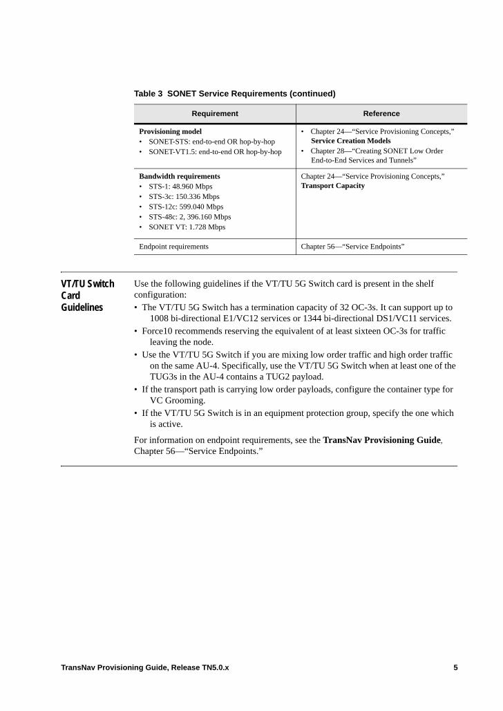
VT/TU Switch Card Guidelines
Use the following guidelines if the VT/TU 5G Switch card is present in the shelf configuration:• The VT/TU 5G Switch has a termination capacity of 32 OC-3s. It can support up to
1008 bi-directional E1/VC12 services or 1344 bi-directional DS1/VC11 services.• Force10 recommends reserving the equivalent of at least sixteen OC-3s for traffic
leaving the node.• Use the VT/TU 5G Switch if you are mixing low order traffic and high order traffic
on the same AU-4. Specifically, use the VT/TU 5G Switch when at least one of the TUG3s in the AU-4 contains a TUG2 payload.
• If the transport path is carrying low order payloads, configure the container type for VC Grooming.
• If the VT/TU 5G Switch is in an equipment protection group, specify the one which is active.
For information on endpoint requirements, see the TransNav Provisioning Guide,
Chapter 56—“Service Endpoints.”
Provisioning model • SONET-STS: end-to-end OR hop-by-hop• SONET-VT1.5: end-to-end OR hop-by-hop
• Chapter 24—“Service Provisioning Concepts,” Service Creation Models
• Chapter 28—“Creating SONET Low Order End-to-End Services and Tunnels”
Bandwidth requirements• STS-1: 48.960 Mbps• STS-3c: 150.336 Mbps• STS-12c: 599.040 Mbps• STS-48c: 2, 396.160 Mbps• SONET VT: 1.728 Mbps
Chapter 24—“Service Provisioning Concepts,” Transport Capacity
Endpoint requirements Chapter 56—“Service Endpoints”
Table 3 SONET Service Requirements (continued)
Requirement Reference
TransNav Provisioning Guide, Release TN5.0.x 5
VTX/VCX Integrated Card Guidelines
Use the following guidelines if a VC cross-connect (VCX) integrated component card is present in the shelf configuration:• The VCX hardware has a termination capacity of 16 STM-1s. It can support up to
504 bi-directional E1/VC12 services or 672 bi-directional DS1/VC11 services.• Force10 recommends reserving the equivalent of at least eight STM-1s for traffic
leaving the node.• Use the VCX card if you are mixing low order traffic and high order traffic on the
same AU-4. Specifically, use the VCX when at least one of the TUG3s in the AU-4 contains a TUG2 payload.
• If the transport path is carrying low order payloads, configure the container type for VC Grooming.
• If the VCX is in an equipment protection group, specify the VCX which is active.
For information on endpoint requirements, see Chapter 56—“Service Endpoints.”
Guidelines to Provision a SONET VT-Mux Service
The guidelines to provision a SONET VT-Mux service are:• The source and destination endpoints must be on cards located on the same node. • One end of the service must terminate on an EoPDH card.• For EOP functions, the VT-Mux service must terminate on one of the first 12 STS
endpoints to generate usable endpoints. EoPDH cards restrict low order connection termination points for use on DS1 cards to reside only in the first 12 STSs of the card’s VOP.
• For EOS functions, the VT-Mux service must terminate on one of the first 24 STS endpoints to generate usable endpoints. This is due to the restriction on EoPDH cards requiring low order connection termination points to reside only in the first 24 STSs of the card’s VOP.
For information on endpoint requirements, see Chapter 56—“Service Endpoints.”
Payload Mapping Parameter
The Payload Mapping parameter is used on high order SONET STS services to allow the system to consider the activated service a clear-channel container with no sub-containers.
When the Payload Mapping parameter is set to STS-1 on SONET STS services, the service is considered a clear-channel container with no lower level VT sub-containers. When the parameter is set to VT1.5, Traverse recognizes the low-level VT sub-containers as individual endpoints on the STS-1. The service endpoint on the EoPDH card is treated as 28 VT1.5 endpoints for use in an EOS or EOP port. For information on EoPDH endpoint requirements, see Chapter 56—“Service Endpoints.”
Automatic in Service
Use Automatic in Service to bring up or take down traffic on a provisioned service without notifying alarms to network operators. Based on Telcordia GR-1093-CORE, when Automatic in Service is enabled, the alarms and performance monitoring reports are suppressed for a user-specified time that is set at the node level. The alarm suppression is automatically removed when traffic is received on the lowest level endpoint (STS or VT1.5) and the user-specified time has been reached. When the suppression is removed, alarms and performance monitoring reports will be reported. Services must be de-activated, then re-activated for the changes to effect the changes.
6 TransNav Provisioning Guide, Release TN5.0.x
The amount of time that alarms and performance monitoring reports are suppressed is set at the node level. The timer remains at the set values for as long as alarms exist and starts decrementing when no service affecting alarms exist. However, new service affecting alarms restart the counter if the counter has not reached 0 minutes.
The Automatic in Service feature is not available on low order end-to-end unidirectional services that originate on Ethernet cards or electrical cards such as DS-3. End-to-end services are unlocked at the source node; because optical alarm monitoring is not performed on the source node for Ethernet and electrical cards, the services will never unlock by themselves.
Note: This feature is currently available only on Traverse SONET services to suppress service level alarms, TCA events, and performance monitoring reports. It is also available on DS-n, EC1, DS3TMX, STM1TMX, and OC-n ports and subports to suppress port level service-affecting alarms and performance monitoring reports. This feature is not available for services on DCS matrix shelves.
Important: Use caution utilizing the Automatic in Service feature on an endpoint on a DS1-MUX, DS3-TMX, STS1-TMX or VT-MUX service. Each STS endpoint on these services have 28 VT1.5 associated endpoints. Only the STS endpoint values display on the Path Display for Service screen, however, the suppression is unlocked when the timer on any single VT1.5 endpoint reaches 0. This can be misleading if the timer for the STS is 0 but the service is in a locked state. If the service is locked, the VT1.5 endpoints are still in a locked state. A quick method to view the associated VT1.5 endpoints is to click the PM tab on the Path Display for Service screen. For more information on the Path Display for Service screen, see the Operations and Maintenance Guide, Chapter 9—“Managing Service Paths,” Showing TxRx Paths.
For more information on suppressing service level alarms, see the Operations and Maintenance Guide, Chapter 2—“Managing Events and Alarms,” Suppressing Alarms and Manually Suppress Port Alarms.
TransNav Provisioning Guide, Release TN5.0.x 7
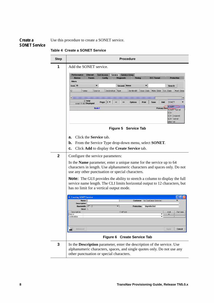
Create a SONET Service
Use this procedure to create a SONET service.
Table 4 Create a SONET Service
Step Procedure
1 Add the SONET service.
Figure 5 Service Tab
a. Click the Service tab.
b. From the Service Type drop-down menu, select SONET.
c. Click Add to display the Create Service tab.
2 Configure the service parameters:
In the Name parameter, enter a unique name for the service up to 64 characters in length. Use alphanumeric characters and spaces only. Do not use any other punctuation or special characters.
Note: The GUI provides the ability to stretch a column to display the full service name length. The CLI limits horizontal output to 12 characters, but has no limit for a vertical output mode.
Figure 6 Create Service Tab
3 In the Description parameter, enter the description of the service. Use alphanumeric characters, spaces, and single quotes only. Do not use any other punctuation or special characters.
8 TransNav Provisioning Guide, Release TN5.0.x
4 In the Customer parameter, select a customer name from the drop-down list box.
5 From the Bandwidth parameter, select the total bandwidth for the service: • VT1.5 (does not apply to 10GbE or GbE-10 cards)• STS-1 (default)• STS-3c (default for 10GbE or GbE-10 cards)• STS-12c (for OC-12 and greater interfaces only)• STS-48c (for OC-48 and greater interfaces only)
Note: EoPDH cards support only VT1.5, STS-1, and STS-3c bandwidths. EoPDH cards are only available on Traverse nodes.
6 Select the Strict check box if this is an end-to-end service to explicitly define the service route through all nodes in the network.
For more information, see Chapter 26—“Common Procedures for Services,” For Strict Services, Configure the Path Through the Network.
Table 4 Create a SONET Service (continued)
Step Procedure
TransNav Provisioning Guide, Release TN5.0.x 9
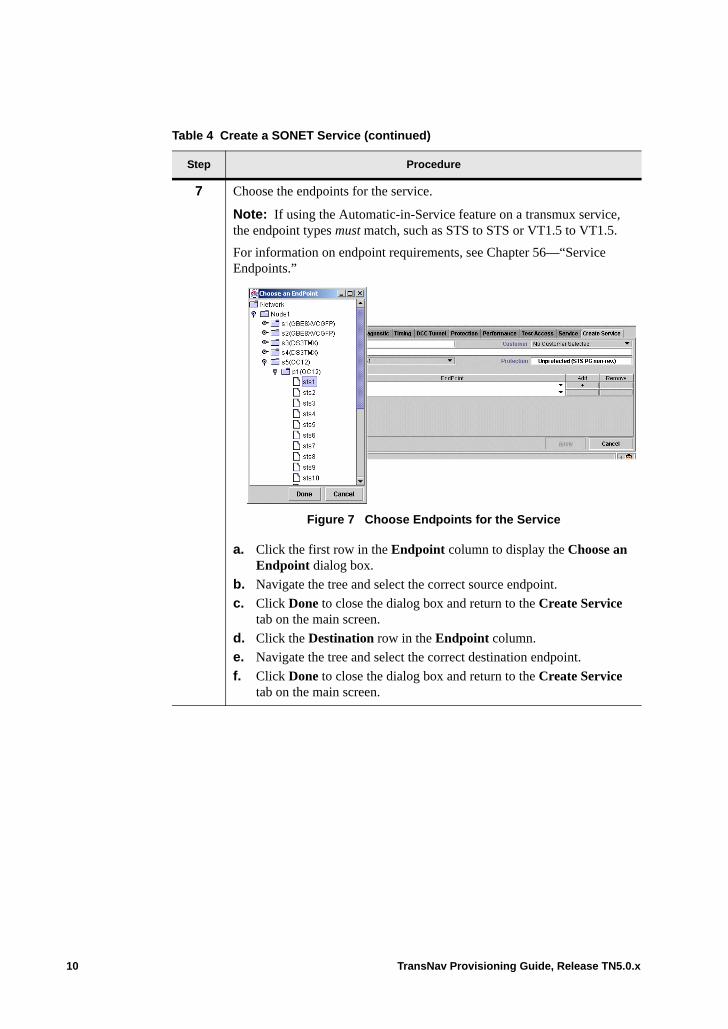
7 Choose the endpoints for the service.
Note: If using the Automatic-in-Service feature on a transmux service, the endpoint types must match, such as STS to STS or VT1.5 to VT1.5.
For information on endpoint requirements, see Chapter 56—“Service Endpoints.”
Figure 7 Choose Endpoints for the Service
a. Click the first row in the Endpoint column to display the Choose an Endpoint dialog box.
b. Navigate the tree and select the correct source endpoint.
c. Click Done to close the dialog box and return to the Create Service tab on the main screen.
d. Click the Destination row in the Endpoint column.
e. Navigate the tree and select the correct destination endpoint.
f. Click Done to close the dialog box and return to the Create Service tab on the main screen.
Table 4 Create a SONET Service (continued)
Step Procedure
10 TransNav Provisioning Guide, Release TN5.0.x
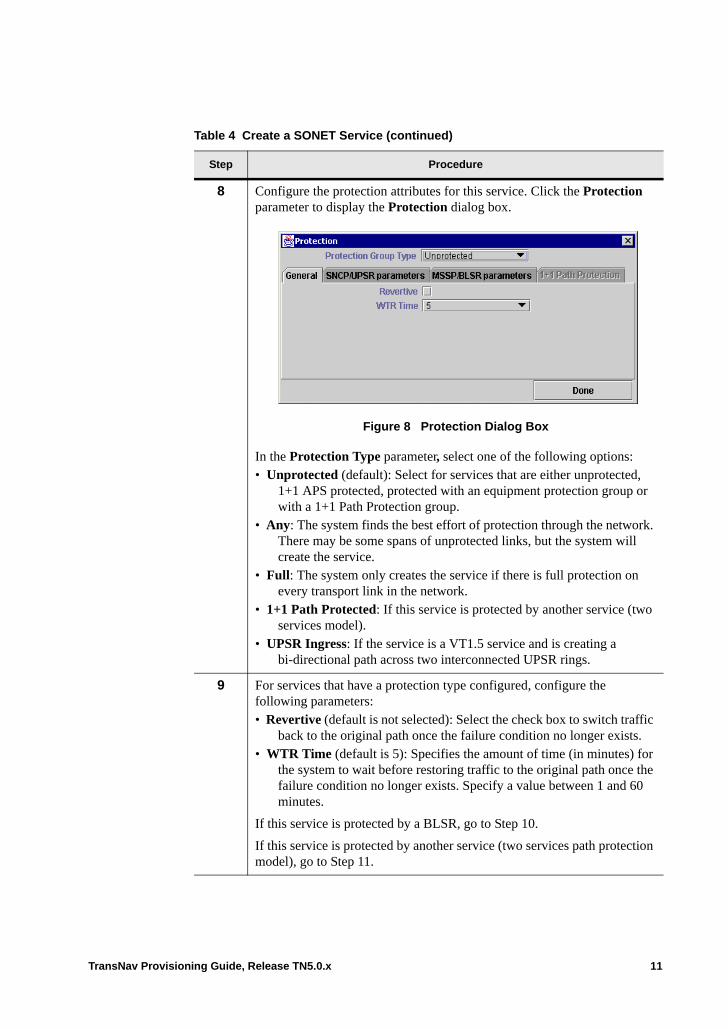
8 Configure the protection attributes for this service. Click the Protection parameter to display the Protection dialog box.
Figure 8 Protection Dialog Box
In the Protection Type parameter, select one of the following options: • Unprotected (default): Select for services that are either unprotected,
1+1 APS protected, protected with an equipment protection group or with a 1+1 Path Protection group.
• Any: The system finds the best effort of protection through the network. There may be some spans of unprotected links, but the system will create the service.
• Full: The system only creates the service if there is full protection on every transport link in the network.
• 1+1 Path Protected: If this service is protected by another service (two services model).
• UPSR Ingress: If the service is a VT1.5 service and is creating a bi-directional path across two interconnected UPSR rings.
9 For services that have a protection type configured, configure the following parameters:• Revertive (default is not selected): Select the check box to switch traffic
back to the original path once the failure condition no longer exists.• WTR Time (default is 5): Specifies the amount of time (in minutes) for
the system to wait before restoring traffic to the original path once the failure condition no longer exists. Specify a value between 1 and 60 minutes.
If this service is protected by a BLSR, go to Step 10.
If this service is protected by another service (two services path protection model), go to Step 11.
Table 4 Create a SONET Service (continued)
Step Procedure
TransNav Provisioning Guide, Release TN5.0.x 11
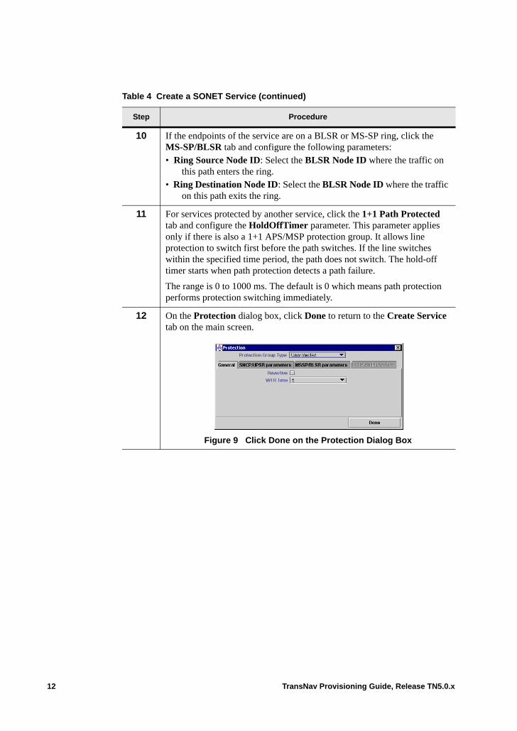
10 If the endpoints of the service are on a BLSR or MS-SP ring, click the MS-SP/BLSR tab and configure the following parameters: • Ring Source Node ID: Select the BLSR Node ID where the traffic on
this path enters the ring.• Ring Destination Node ID: Select the BLSR Node ID where the traffic
on this path exits the ring.
11 For services protected by another service, click the 1+1 Path Protected tab and configure the HoldOffTimer parameter. This parameter applies only if there is also a 1+1 APS/MSP protection group. It allows line protection to switch first before the path switches. If the line switches within the specified time period, the path does not switch. The hold-off timer starts when path protection detects a path failure.
The range is 0 to 1000 ms. The default is 0 which means path protection performs protection switching immediately.
12 On the Protection dialog box, click Done to return to the Create Service tab on the main screen.
Figure 9 Click Done on the Protection Dialog Box
Table 4 Create a SONET Service (continued)
Step Procedure
12 TransNav Provisioning Guide, Release TN5.0.x

13 On the Create Service tab, click Advanced to configure more parameters of the service.
Figure 10 Advanced Parameters Dialog Box
For specific definitions of these parameters, see Chapter 26—“Common Procedures for Services,” Configure Advanced Parameters (Alphabetic Order).
To provision a VT-MUX service, continue to Step 14.
To complete the service, skip to Step 15.
Table 4 Create a SONET Service (continued)
Step Procedure
TransNav Provisioning Guide, Release TN5.0.x 13
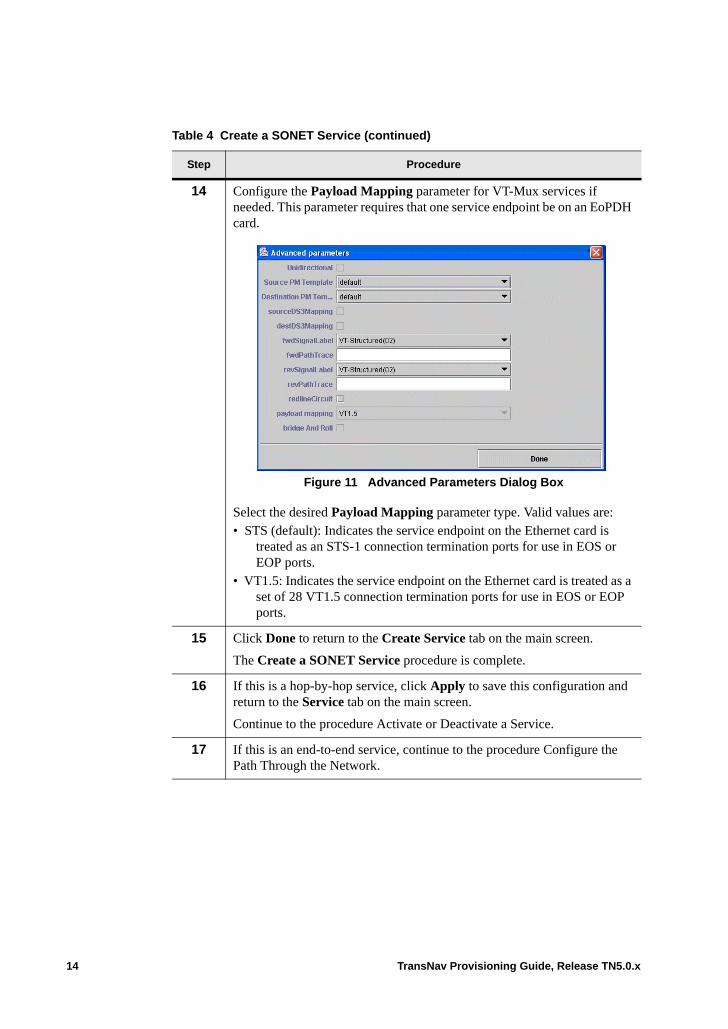
14 Configure the Payload Mapping parameter for VT-Mux services if needed. This parameter requires that one service endpoint be on an EoPDH card.
Figure 11 Advanced Parameters Dialog Box
Select the desired Payload Mapping parameter type. Valid values are: • STS (default): Indicates the service endpoint on the Ethernet card is
treated as an STS-1 connection termination ports for use in EOS or EOP ports.
• VT1.5: Indicates the service endpoint on the Ethernet card is treated as a set of 28 VT1.5 connection termination ports for use in EOS or EOP ports.
15 Click Done to return to the Create Service tab on the main screen.
The Create a SONET Service procedure is complete.
16 If this is a hop-by-hop service, click Apply to save this configuration and return to the Service tab on the main screen.
Continue to the procedure Activate or Deactivate a Service.
17 If this is an end-to-end service, continue to the procedure Configure the Path Through the Network.
Table 4 Create a SONET Service (continued)
Step Procedure
14 TransNav Provisioning Guide, Release TN5.0.x
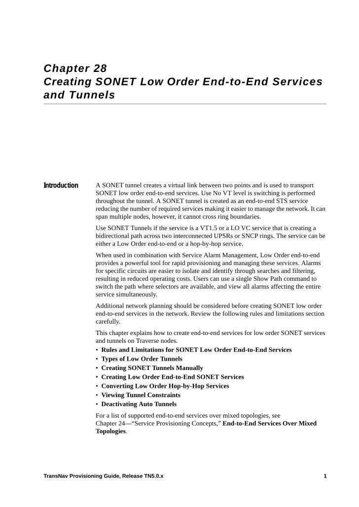
Chapter 28 Creating SONET Low Order End-to-End Services and Tunnels
Introduction A SONET tunnel creates a virtual link between two points and is used to transport SONET low order end-to-end services. Use No VT level is switching is performed throughout the tunnel. A SONET tunnel is created as an end-to-end STS service reducing the number of required services making it easier to manage the network. It can span multiple nodes, however, it cannot cross ring boundaries.
Use SONET Tunnels if the service is a VT1.5 or a LO VC service that is creating a bidirectional path across two interconnected UPSRs or SNCP rings. The service can be either a Low Order end-to-end or a hop-by-hop service.
When used in combination with Service Alarm Management, Low Order end-to-end provides a powerful tool for rapid provisioning and managing these services. Alarms for specific circuits are easier to isolate and identify through searches and filtering, resulting in reduced operating costs. Users can use a single Show Path command to switch the path where selectors are available, and view all alarms affecting the entire service simultaneously.
Additional network planning should be considered before creating SONET low order end-to-end services in the network. Review the following rules and limitations section carefully.
This chapter explains how to create end-to-end services for low order SONET services and tunnels on Traverse nodes. • Rules and Limitations for SONET Low Order End-to-End Services• Types of Low Order Tunnels• Creating SONET Tunnels Manually• Creating Low Order End-to-End SONET Services• Converting Low Order Hop-by-Hop Services• Viewing Tunnel Constraints• Deactivating Auto Tunnels
For a list of supported end-to-end services over mixed topologies, see Chapter 24—“Service Provisioning Concepts,” End-to-End Services Over Mixed Topologies.
TransNav Provisioning Guide, Release TN5.0.x 1
If your system includes 2-port OC-48 cards, see Chapter 28—“Creating SONET Low Order End-to-End Services and Tunnels” for additional information.
Rules and Limitations for SONET Low Order End-to-End Services
The maximum number of Low Order end-to-end services that a node can support is determined by a large number of factors. Each node supports a maximum of 500 VT1.5 bandwidth tunneled services on a GCM card such as a source or destination endpoint or a pass-through service. If a UGCM-XM card is used, system supports a maximum number of 800 tunneled services The Low Order end-to-end services can be routed using tunnels that are created either manually or automatically. Automatic tunnels are created by the system as needed.
All hop information for the entire Low Order end-to-end service is kept on the source node. Additional resources, including memory, are consumed on the head node. Depending on the loading at the head node, this may result in limitations on the number of end-to-end services ingressing from a node.
The following rules apply when creating low order end-to-end services:• Both the source and destination must have VT cards. • Ring interconnecting nodes used for low order end-to-end services must have VT
cards. • If on a BLSR ring, the source and destination endpoints of a tunnel must use the same
STS number. • Create the manual tunnels before creating the low-order end-to-end services. If no
manual tunnel exists, the system creates a tunnel automatically (called an AutoTunnel) if additional bandwidth is available. The system automatically routes additional services to the same tunnel.
• SONET end-to-end services must be either fully loose or fully strict.– Fully loose services:
- will use VT cards along the working and protect paths whenever possible, except for BLSR services which require tunnels between both endpoints/ring boundaries.
- will use existing activated tunnels when available. The tunnels can be created either manually or automatically.
- will create auto-tunnels, if needed.- will not require or create tunnels if every hop between the source and
destination along a path has VT cards unless the end-to-end service is in a BLSR ring.
– For fully strict services:- Additional hops (path constraints) can only be tunnel endpoints.- Path constraints should be entered in egress/ingress pairs as shown in the
following example:- Can use provisioned or activated tunnels that have been created either
manually or automatically.• DS1 ports used in a hop-by-hop configuration will limit the selection of other ports
on the card for end-to-end provisioning.
2 TransNav Provisioning Guide, Release TN5.0.x
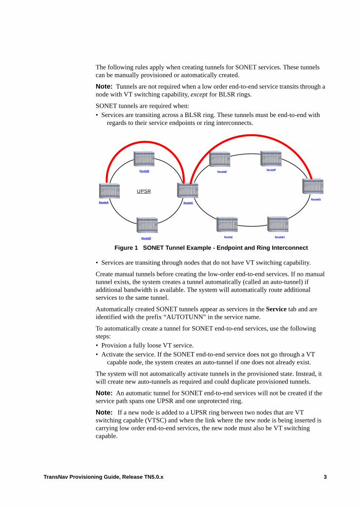
The following rules apply when creating tunnels for SONET services. These tunnels can be manually provisioned or automatically created.
Note: Tunnels are not required when a low order end-to-end service transits through a node with VT switching capability, except for BLSR rings.
SONET tunnels are required when:• Services are transiting across a BLSR ring. These tunnels must be end-to-end with
regards to their service endpoints or ring interconnects.
Figure 1 SONET Tunnel Example - Endpoint and Ring Interconnect
• Services are transiting through nodes that do not have VT switching capability.
Create manual tunnels before creating the low-order end-to-end services. If no manual tunnel exists, the system creates a tunnel automatically (called an auto-tunnel) if additional bandwidth is available. The system will automatically route additional services to the same tunnel.
Automatically created SONET tunnels appear as services in the Service tab and are identified with the prefix “AUTOTUNN” in the service name.
To automatically create a tunnel for SONET end-to-end services, use the following steps: • Provision a fully loose VT service. • Activate the service. If the SONET end-to-end service does not go through a VT
capable node, the system creates an auto-tunnel if one does not already exist.
The system will not automatically activate tunnels in the provisioned state. Instead, it will create new auto-tunnels as required and could duplicate provisioned tunnels.
Note: An automatic tunnel for SONET end-to-end services will not be created if the service path spans one UPSR and one unprotected ring.
Note: If a new node is added to a UPSR ring between two nodes that are VT switching capable (VTSC) and when the link where the new node is being inserted is carrying low order end-to-end services, the new node must also be VT switching capable.
NodeENodeF
NodeI
UPSR
NodeB
NodeCNodeA
NodeH
NodeG
NodeD
TransNav Provisioning Guide, Release TN5.0.x 3

To show tunneled services, from the Service tab, right-click the tunnel, then select Tunnel, Show Tunneled Services.
Figure 2 Low Order End-to-End Show Tunnel Services
To see constraints on the tunnel, right click the auto-tunnel service on the Service tab, select Tunnel, then Show Tunnel Constraints.
Types of Low Order Tunnels
Two types of low order SONET tunnels are available: • Manual tunnels: allow users more control of the path to be used for the tunnel• Auto-tunnels: automatically created by the system
Manual tunnels are STS-level SONET tunnels that are created to the user’s specifications. A SONET tunnel is a High Order STS service that creates a virtual link between two VT-capable nodes. It is used to transport up to 28 VT1.5 low order end-to-end services between the nodes through one or more nodes that are not VT capable (1 STS has 28 VT1.5s).
To create a manual tunnel, the user selects the source and destination endpoints (and optionally transit path constraints) to transport a low-order service through a non-VT capable node. For instance, if a Low Order end-to-end service is desired between nodes A and E (A—B—C—D—E) where all nodes except C are VT-capable, the user can create a manual SONET tunnel between B and D by selecting STSs on the trunk (link endpoint) slot and port between B and C, and between C and D. This manual tunnel is at the STS level and has the bandwidth of one STS. Once the manual tunnel is created, it can be used to transport up to 28 Low Order end-to-end services between A and E. These services use the manual tunnel between B and D nodes. If more than 28 Low
4 TransNav Provisioning Guide, Release TN5.0.x
Order end-to-end services are created, the bandwidth of the manual tunnel previously created is exhausted and a new tunnel must be created. For more information on service creation models, see Chapter 24—“Service Provisioning Concepts,” Service Creation Models.
Automatic tunnels are automatically created by the system if a manual tunnel is unavailable and:• a Low Order end-to-end service transits a non-VT capable node, or • a Low Order end-to-end service is on a BLSR ring.
Using the previous example, if a Low Order end-to-end service is desired between nodes A and E (A—B—C—D—E) where all nodes except C are VT-capable, the system creates an auto-tunnel from B to D by selecting an STS from the available STSs between B and C and between C and D. The STS selection is performed automatically by the system software.
If no tunnel is available, an auto-tunnel will be created by the system if sufficient bandwidth is available.
No VT level switching is performed throughout the tunnel. A SONET tunnel is created as an end-to-end STS service. It can span multiple nodes, however, it cannot cross ring boundaries.
Once created, the SONET tunnel can be used for either Low Order end-to-end services or for hop-by-hop services.
Supported topologies. Low Order end-to-end tunneled services are supported on the following topologies: • UPSR (Concentric UPSR rings are not supported for protected Low Order end-to-end
services.)
• 1+1 LAPS• Mesh• BLSR:
– Supports both single and concentric BLSR topologies - Concentric BLSR rings are treated as individual rings
– BLSR rings require the creation of an auto-tunnel for the portion of the path traversing the BLSR, if no existing tunnel is available
– The source and destination endpoints of a tunnel must use the same STS number on a BLSR ring.
• Combination topologies: the interconnecting node must be VT capable.– Multi-ring (including mixed UPSR/BLSR) – Ring and 1+1 Linear APS– Ring and Mesh– Mesh and 1+1 Linear APS
Automatic tunnels for SONET end-to-end services will not be created if the service path spans one UPSR and one unprotected ring.
For Low Order end-to-end services, the source endpoint must be the same for both the Unprotected and the 1+1 Path Protected service. This service model will be common when dropping protected traffic to a dual connect non-Traverse, such as a core Traverse
TransNav Provisioning Guide, Release TN5.0.x 5

ring with a sub-tending TraverseEdge 100 collector ring as shown in Chapter 24—“Service Provisioning Concepts,” End-to-End Services Over Mixed Topologies, Figure 4 Low Order End-to-End Service with Path Protection.
Creating SONET Tunnels Manually
Prior to creating low order end-to-end SONET services, you can create SONET tunnels manually to select the nodes to be used for the tunnel. This allow better selection of the service path to be used if so desired.
Note: From the TransNav GUI, you can view which nodes are VT capable to help create low order end-to-end services. To enable this feature, select Admin, Options, then click the VT Capability tab. Select the Show VT/VC Switching Capability On Map check box.
Table 3 Creating SONET Tunnels Manually
Step Procedure
1 Create a SONET Tunnel.
Figure 4 Select Tunnel Service Type
a. Click the Service tab.
b. From the Service drop-down menu, select SONET Tunnel.
c. Click Add to display the Create Service dialog box.
6 TransNav Provisioning Guide, Release TN5.0.x
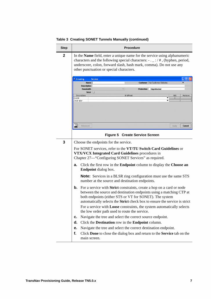
2 In the Name field, enter a unique name for the service using alphanumeric characters and the following special characters: - . _ : / # , (hyphen, period, underscore, colon, forward slash, hash mark, comma). Do not use any other punctuation or special characters.
Figure 5 Create Service Screen
3 Choose the endpoints for the service.
For SONET services, refer to the VT/TU Switch Card Guidelines or VTX/VCX Integrated Card Guidelines procedures in Chapter 27—“Configuring SONET Services” as required.
a. Click the first row in the Endpoint column to display the Choose an Endpoint dialog box.
Note: Services in a BLSR ring configuration must use the same STS number at the source and destination endpoints.
b. For a service with Strict constraints, create a hop on a card or node between the source and destination endpoints using a matching CTP at both endpoints (either STS or VT for SONET). The system automatically selects the Strict check box to ensure the service is strictFor a service with Loose constraints, the system automatically selects the low order path used to route the service.
c. Navigate the tree and select the correct source endpoint.
d. Click the Destination row in the Endpoint column.
e. Navigate the tree and select the correct destination endpoint.
f. Click Done to close the dialog box and return to the Service tab on the main screen.
Table 3 Creating SONET Tunnels Manually (continued)
Step Procedure
TransNav Provisioning Guide, Release TN5.0.x 7
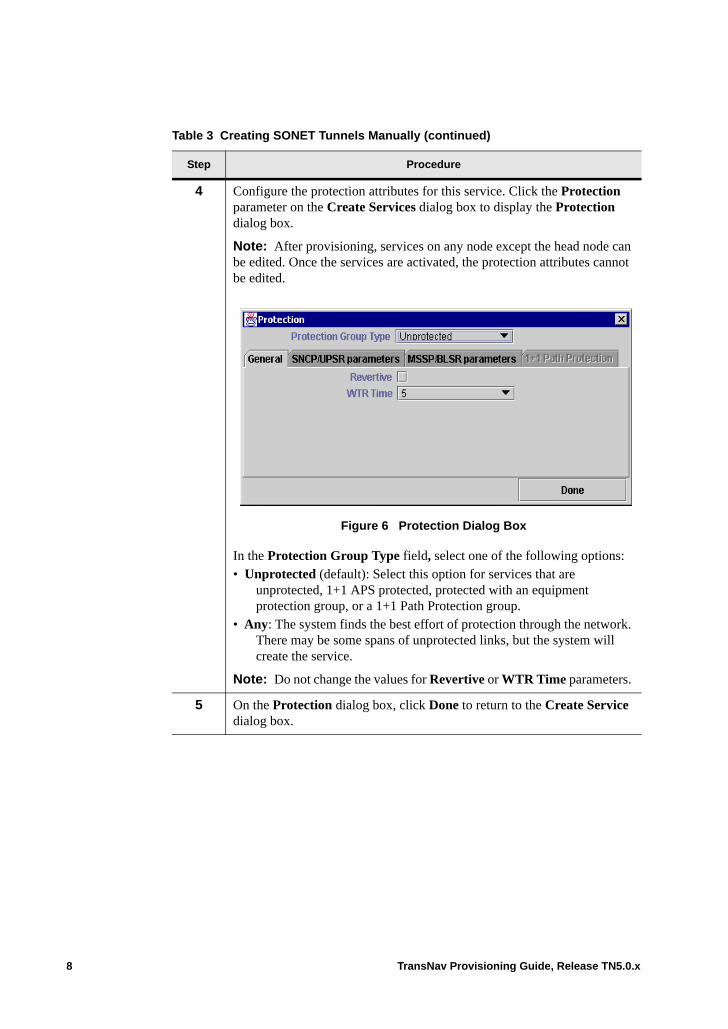
4 Configure the protection attributes for this service. Click the Protection parameter on the Create Services dialog box to display the Protection dialog box.
Note: After provisioning, services on any node except the head node can be edited. Once the services are activated, the protection attributes cannot be edited.
Figure 6 Protection Dialog Box
In the Protection Group Type field, select one of the following options: • Unprotected (default): Select this option for services that are
unprotected, 1+1 APS protected, protected with an equipment protection group, or a 1+1 Path Protection group.
• Any: The system finds the best effort of protection through the network. There may be some spans of unprotected links, but the system will create the service.
Note: Do not change the values for Revertive or WTR Time parameters.
5 On the Protection dialog box, click Done to return to the Create Service dialog box.
Table 3 Creating SONET Tunnels Manually (continued)
Step Procedure
8 TransNav Provisioning Guide, Release TN5.0.x
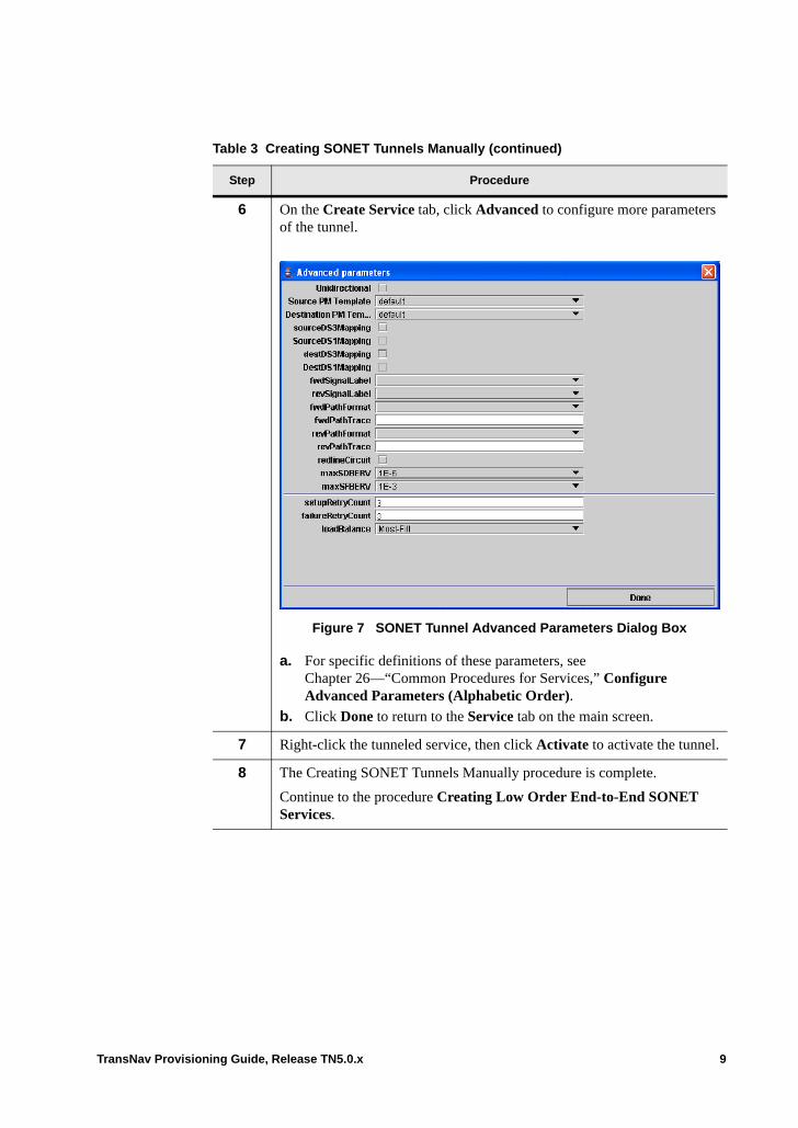
6 On the Create Service tab, click Advanced to configure more parameters of the tunnel.
Figure 7 SONET Tunnel Advanced Parameters Dialog Box
a. For specific definitions of these parameters, see Chapter 26—“Common Procedures for Services,” Configure Advanced Parameters (Alphabetic Order).
b. Click Done to return to the Service tab on the main screen.
7 Right-click the tunneled service, then click Activate to activate the tunnel.
8 The Creating SONET Tunnels Manually procedure is complete.
Continue to the procedure Creating Low Order End-to-End SONET Services.
Table 3 Creating SONET Tunnels Manually (continued)
Step Procedure
TransNav Provisioning Guide, Release TN5.0.x 9
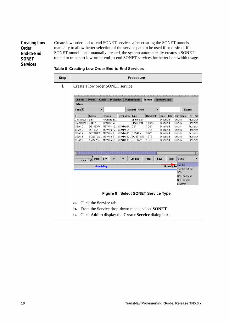
Creating Low Order End-to-End SONET Services
Create low order end-to-end SONET services after creating the SONET tunnels manually to allow better selection of the service path to be used if so desired. If a SONET tunnel is not manually created, the system automatically creates a SONET tunnel to transport low-order end-to-end SONET services for better bandwidth usage.
Table 8 Creating Low Order End-to-End Services
Step Procedure
1 Create a low order SONET service.
Figure 9 Select SONET Service Type
a. Click the Service tab.
b. From the Service drop-down menu, select SONET.
c. Click Add to display the Create Service dialog box.
10 TransNav Provisioning Guide, Release TN5.0.x
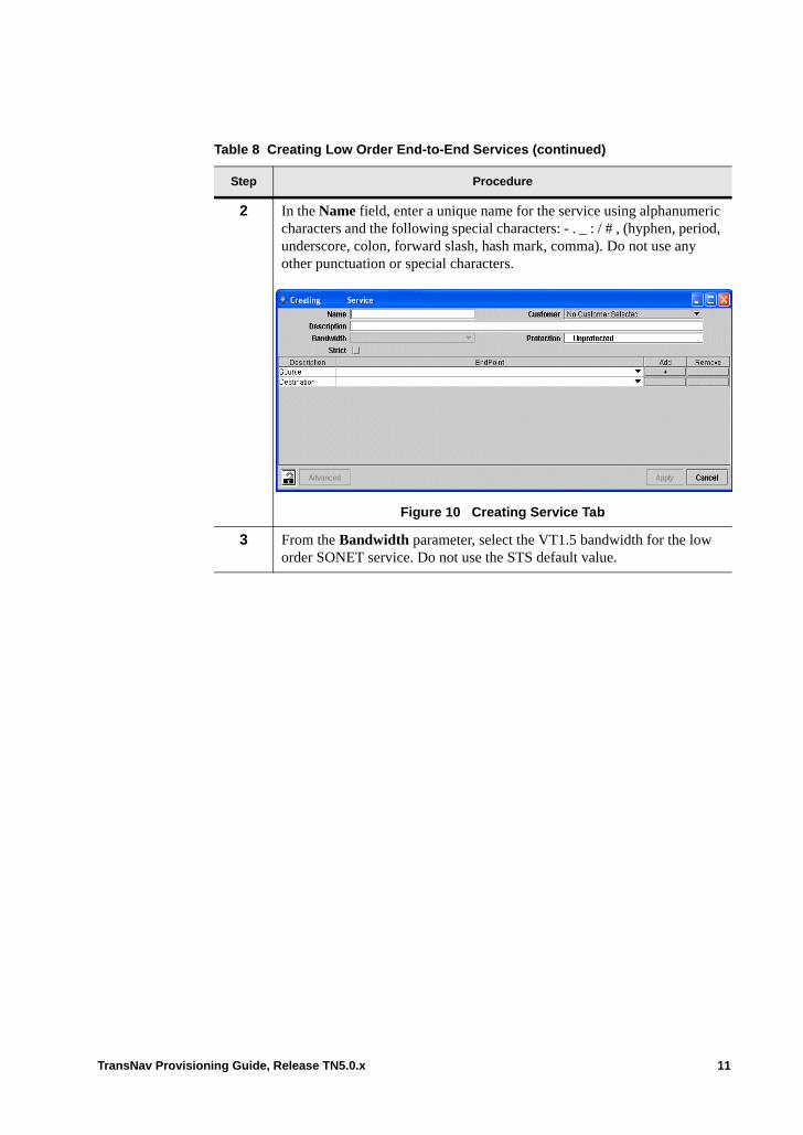
2 In the Name field, enter a unique name for the service using alphanumeric characters and the following special characters: - . _ : / # , (hyphen, period, underscore, colon, forward slash, hash mark, comma). Do not use any other punctuation or special characters.
Figure 10 Creating Service Tab
3 From the Bandwidth parameter, select the VT1.5 bandwidth for the low order SONET service. Do not use the STS default value.
Table 8 Creating Low Order End-to-End Services (continued)
Step Procedure
TransNav Provisioning Guide, Release TN5.0.x 11
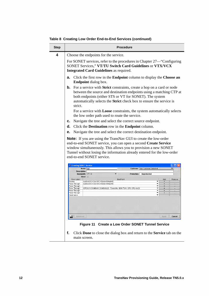
4 Choose the endpoints for the service.
For SONET services, refer to the procedures in Chapter 27—“Configuring SONET Services,” VT/TU Switch Card Guidelines or VTX/VCX Integrated Card Guidelines as required.
a. Click the first row in the Endpoint column to display the Choose an Endpoint dialog box.
b. For a service with Strict constraints, create a hop on a card or node between the source and destination endpoints using a matching CTP at both endpoints (either STS or VT for SONET). The system automatically selects the Strict check box to ensure the service is strict. For a service with Loose constraints, the system automatically selects the low order path used to route the service.
c. Navigate the tree and select the correct source endpoint.
d. Click the Destination row in the Endpoint column.
e. Navigate the tree and select the correct destination endpoint.
Note: If you are using the TransNav GUI to create the low-order end-to-end SONET service, you can open a second Create Service window simultaneously. This allows you to provision a new SONET Tunnel without losing the information already entered for the low-order end-to-end SONET service.
Figure 11 Create a Low Order SONET Tunnel Service
f. Click Done to close the dialog box and return to the Service tab on the main screen.
Table 8 Creating Low Order End-to-End Services (continued)
Step Procedure
12 TransNav Provisioning Guide, Release TN5.0.x
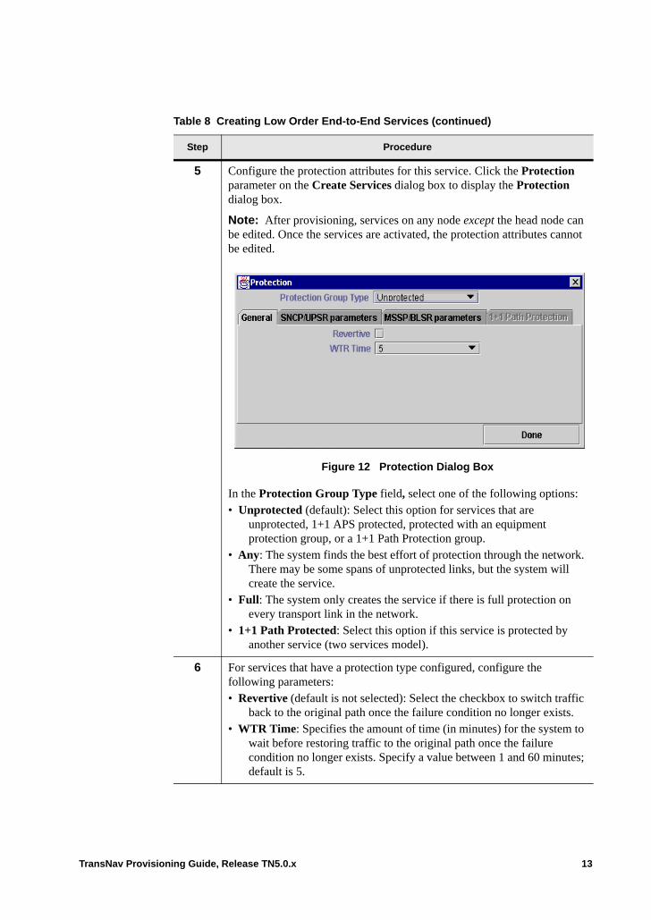
5 Configure the protection attributes for this service. Click the Protection parameter on the Create Services dialog box to display the Protection dialog box.
Note: After provisioning, services on any node except the head node can be edited. Once the services are activated, the protection attributes cannot be edited.
Figure 12 Protection Dialog Box
In the Protection Group Type field, select one of the following options: • Unprotected (default): Select this option for services that are
unprotected, 1+1 APS protected, protected with an equipment protection group, or a 1+1 Path Protection group.
• Any: The system finds the best effort of protection through the network. There may be some spans of unprotected links, but the system will create the service.
• Full: The system only creates the service if there is full protection on every transport link in the network.
• 1+1 Path Protected: Select this option if this service is protected by another service (two services model).
6 For services that have a protection type configured, configure the following parameters:• Revertive (default is not selected): Select the checkbox to switch traffic
back to the original path once the failure condition no longer exists.• WTR Time: Specifies the amount of time (in minutes) for the system to
wait before restoring traffic to the original path once the failure condition no longer exists. Specify a value between 1 and 60 minutes; default is 5.
Table 8 Creating Low Order End-to-End Services (continued)
Step Procedure
TransNav Provisioning Guide, Release TN5.0.x 13
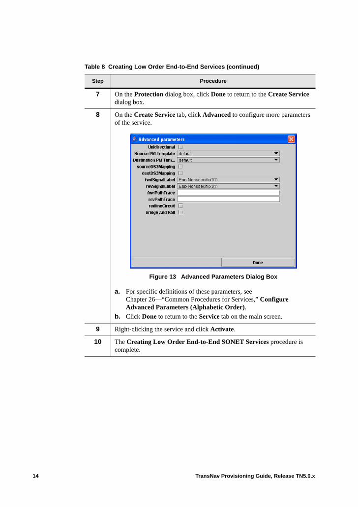
7 On the Protection dialog box, click Done to return to the Create Service dialog box.
8 On the Create Service tab, click Advanced to configure more parameters of the service.
Figure 13 Advanced Parameters Dialog Box
a. For specific definitions of these parameters, see Chapter 26—“Common Procedures for Services,” Configure Advanced Parameters (Alphabetic Order).
b. Click Done to return to the Service tab on the main screen.
9 Right-clicking the service and click Activate.
10 The Creating Low Order End-to-End SONET Services procedure is complete.
Table 8 Creating Low Order End-to-End Services (continued)
Step Procedure
14 TransNav Provisioning Guide, Release TN5.0.x
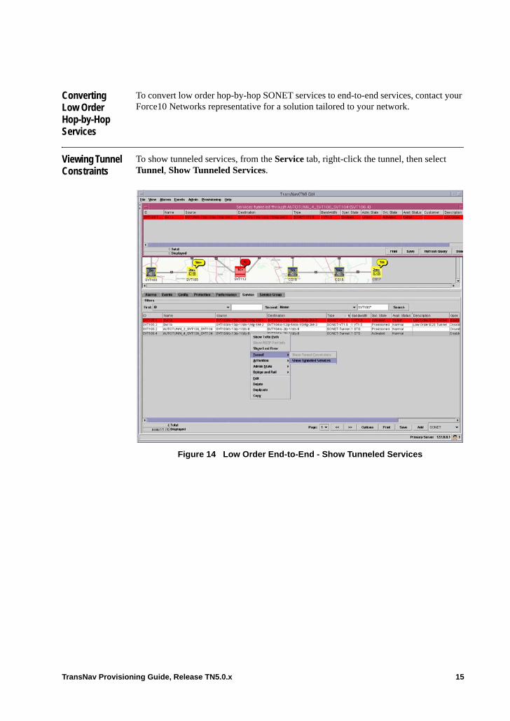
Converting Low Order Hop-by-Hop Services
To convert low order hop-by-hop SONET services to end-to-end services, contact your Force10 Networks representative for a solution tailored to your network.
Viewing Tunnel Constraints
To show tunneled services, from the Service tab, right-click the tunnel, then select Tunnel, Show Tunneled Services.
Figure 14 Low Order End-to-End - Show Tunneled Services
TransNav Provisioning Guide, Release TN5.0.x 15
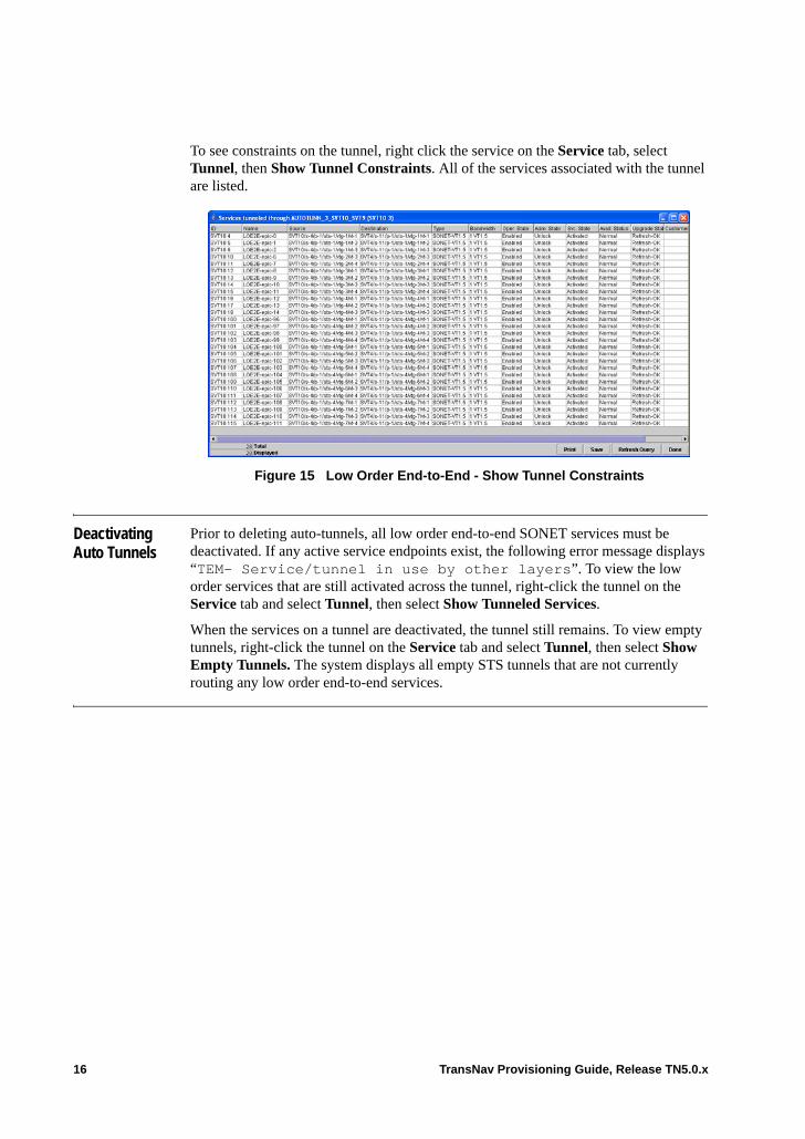
To see constraints on the tunnel, right click the service on the Service tab, select Tunnel, then Show Tunnel Constraints. All of the services associated with the tunnel are listed.
Figure 15 Low Order End-to-End - Show Tunnel Constraints
Deactivating Auto Tunnels
Prior to deleting auto-tunnels, all low order end-to-end SONET services must be deactivated. If any active service endpoints exist, the following error message displays “TEM- Service/tunnel in use by other layers”. To view the low order services that are still activated across the tunnel, right-click the tunnel on the Service tab and select Tunnel, then select Show Tunneled Services.
When the services on a tunnel are deactivated, the tunnel still remains. To view empty tunnels, right-click the tunnel on the Service tab and select Tunnel, then select Show Empty Tunnels. The system displays all empty STS tunnels that are not currently routing any low order end-to-end services.
16 TransNav Provisioning Guide, Release TN5.0.x
Chapter 29 Configuring SDH Services
Introduction This chapter explains how to create the following service types in a Traverse network:• SDH: Use this service to transport synchronous traffic through the network. Also, use
this service as a regular cross-connect when creating a transport path hop-by-hop through the network.
• SDH Endpoint: Use this service to create a termination point to multiplex low order traffic into the network. Also use this service to create a transport path hop-by-hop through the network.
• SDH-Tunnel. Use this service to create a transport path end-to-end through the network.
This chapter includes the following topics:• Multiplexing Mixed Traffic onto a VC-4 Transport Path• Cards Required to Create SDH Services• Other SDH Services and Applications• Before You Create SDH Services• VT/TU 5G Switch Card SDH Guidelines• SDH Switching Guidelines• Create an SDH Service• Create a Low Order SDH Service Across Multiple VT/TU Cards• Create an SDH Endpoint or Tunnel Service• Create an SDH Transport Path Hop-by-Hop• Create an SDH Transport Path End-to-End
For a list of supported end-to-end services over mixed topologies, see Chapter 24—“Service Provisioning Concepts,” End-to-End Services Over Mixed Topologies.
If your system includes 2-port OC-48 cards, see Chapter 30—“Creating 2-Port OC-48/STM-16 Services” for additional information.
TransNav Provisioning Guide, Release TN5.0.x 1
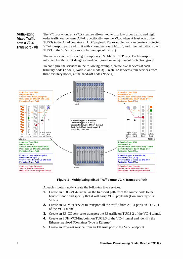
Multiplexing Mixed Traffic onto a VC-4 Transport Path
The VC cross-connect (VCX) feature allows you to mix low order traffic and high order traffic on the same AU-4. Specifically, use the VCX when at least one of the TUG3s in the AU-4 contains a TUG2 payload. For example, you can create a protected VC-4 transport path and fill it with a combination of E1, E3, and Ethernet traffic. (Each TUG3 in the VC-4 can carry only one type of traffic.)
The network in the following example is an STM-16 SNCP ring. Each transport interface has the VCX daughter card configured in an equipment protection group.
To configure the services in the following example, create five services at each tributary node (Node 1, Node 2, and Node 3). Create 12 services (four services from three tributary nodes) at the hand-off node (Node 4).
Figure 1 Multiplexing Mixed Traffic onto VC-4 Transport Path
At each tributary node, create the following five services:
1. Create an SDH-VC4-Tunnel as the transport path from the source node to the hand-off node and specify that it will carry VC-3 payloads (Container Type is VC-3).
2. Create an E1-Mux service to transport all the traffic from 21 E1 ports on TUG3-1 of the VC-4 tunnel.
3. Create an E3-CC service to transport the E3 traffic on TUG3-2 of the VC-4 tunnel.
4. Create an SDH-VC3-Endpoint on TUG3.3 of the VC-4 tunnel and identify the Ethernet payload (Container Type is Ethernet).
5. Create an Ethernet service from an Ethernet port to the VC-3 endpoint.
4. Service Type: SDH-EndpointBandwitdh: VC4 (VC3)Source: Node 1/s-14/p-1/a-1/t3-3/vc3Protection Type: FULL
2. Service Type: SDHBandwitdh: VC3Source: Node 1/ slot-2/all portsDest: Node 1/s-14/p-1/A-1/t3-1/vc3Protection Type: FULL
5. Service Type: EthernetSource: Node 1/slot-8/port-8Dest: Node 1 SDH-Endpoint Service
1. Service Type: SDH-TunnelContainer Type: VC4 (VC-3)Source: Node 1/slot-14/port-1/aug1-1Dest: Node 3/slot-1/port-1/aug1-1Protection Type: FULL
3. Service Type: SDHBandwidth: VC3Source: Node 1/ slot-4/port-1 E3CCDest: Node 1/s-14/p-1/a-1/t3-2/vc3Protection Type: FULL
6. Service Type: SDHBandwidth: VC3Source: Node 3/slot-1/port-1/tug3-1/vc3Dest: Node 3/slot-8/port-1/tug3-1/vc3Protection Type: FULL
7. Service Type: SDHBandwidth: VC3Source: Node 3/slot-1/port-1/tug3-2/vc3Dest: Node 3/slot-8/port-2/tug3-1/vc3Protection Type: FULL
9. Service Type: EthernetSource: Node 3/slot-6/port-4 - GBEDest: Node 3 SDH-Endpoint Service
Node 1 Node 3
W E
Slot 2
STM16VCX
Slot 1
STM16VCX
6.
7.
9.
STM1Slot 8
W E
STM16VCX
Slot 14
STM16VCX
Slot 13
2.
3.
5.
Slot 2E1
Slot 4E3
Slot 8ETH
4.
8. Service Type: SDH-EndpointBandwidth: VC4 (VC3)Source: Node 1/ s-12/p-1/a-1/t3-3/vc3Protection Type: FULL
Slot 6GBE
8.
Node 2
Node 4
2 TransNav Provisioning Guide, Release TN5.0.x
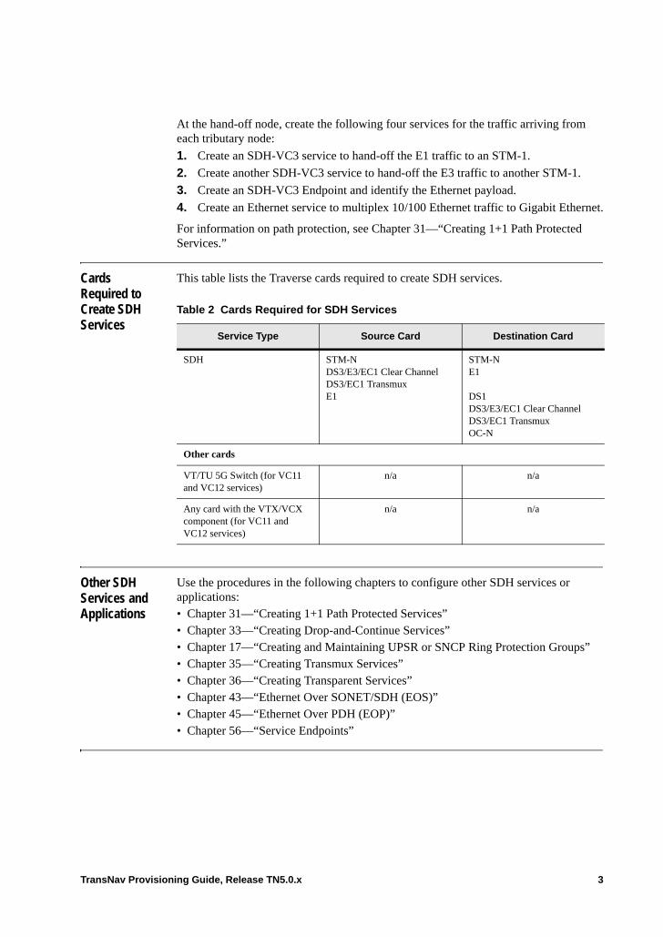
At the hand-off node, create the following four services for the traffic arriving from each tributary node:
1. Create an SDH-VC3 service to hand-off the E1 traffic to an STM-1.
2. Create another SDH-VC3 service to hand-off the E3 traffic to another STM-1.
3. Create an SDH-VC3 Endpoint and identify the Ethernet payload.
4. Create an Ethernet service to multiplex 10/100 Ethernet traffic to Gigabit Ethernet.
For information on path protection, see Chapter 31—“Creating 1+1 Path Protected Services.”
Cards Required to Create SDH Services
This table lists the Traverse cards required to create SDH services.
Other SDH Services and Applications
Use the procedures in the following chapters to configure other SDH services or applications: • Chapter 31—“Creating 1+1 Path Protected Services”• Chapter 33—“Creating Drop-and-Continue Services”• Chapter 17—“Creating and Maintaining UPSR or SNCP Ring Protection Groups”• Chapter 35—“Creating Transmux Services”• Chapter 36—“Creating Transparent Services”• Chapter 43—“Ethernet Over SONET/SDH (EOS)”• Chapter 45—“Ethernet Over PDH (EOP)”• Chapter 56—“Service Endpoints”
Table 2 Cards Required for SDH Services
Service Type Source Card Destination Card
SDH STM-NDS3/E3/EC1 Clear ChannelDS3/EC1 TransmuxE1
STM-NE1
DS1DS3/E3/EC1 Clear ChannelDS3/EC1 TransmuxOC-N
Other cards
VT/TU 5G Switch (for VC11 and VC12 services)
n/a n/a
Any card with the VTX/VCX component (for VC11 and VC12 services)
n/a n/a
TransNav Provisioning Guide, Release TN5.0.x 3
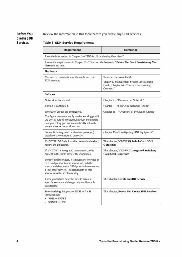
Before You Create SDH Services
Review the information in this topic before you create any SDH services.
Table 3 SDH Service Requirements
Requirement Reference
Read the information in Chapter 1—“TN5.0.x Provisioning Overview.”
Ensure the requirements in Chapter 2—“Discover the Network,” Before You Start Provisioning Your Network are met.
Hardware
You need a combination of the cards to create SDH services.
Traverse Hardware Guide
TransNav Management System Provisioning Guide, Chapter 24—“Service Provisioning Concepts”
Software
Network is discovered. Chapter 2—“Discover the Network”
Timing is configured. Chapter 3—“Configure Network Timing”
Protection groups are configured.
Configure parameters only on the working port if the port is part of a protection group. Parameters on a protecting port are automatically set to the same values as the working port.
Chapter 15—“Overview of Protection Groups”
Source (tributary) and destination (transport) interfaces are configured correctly.
Chapter 11—“Configuring SDH Equipment”
If a VT/TU 5G Switch card is present in the shelf, review the guidelines.
This chapter, VT/TU 5G Switch Card SDH Guidelines
If a VTX/VCX integrated component card is present in the shelf, review the guidelines.
This chapter, VTX/VCX Integrated Switching Card SDH Guidelines
For low order services, it is necessary to create an SDH endpoint or tunnel service on both the source and destination STM ports before creating a low order service. The Bandwidth of this service must be VC Grooming.
These procedures describe how to create a specific service and change only configurable parameters.
This chapter, Create an SDH Service
Interworking. Support for ETSI to ANSI interworking:• SDH to SONET• SONET to SDH
This chapter, Before You Create SDH Services
4 TransNav Provisioning Guide, Release TN5.0.x
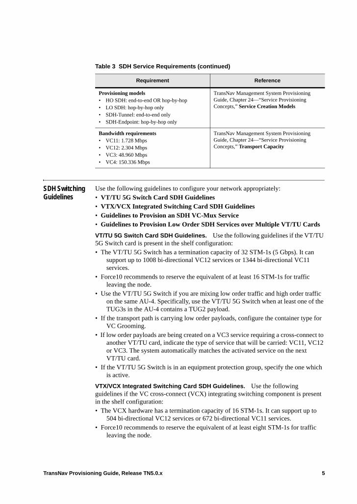
SDH Switching Guidelines
Use the following guidelines to configure your network appropriately: • VT/TU 5G Switch Card SDH Guidelines• VTX/VCX Integrated Switching Card SDH Guidelines• Guidelines to Provision an SDH VC-Mux Service• Guidelines to Provision Low Order SDH Services over Multiple VT/TU Cards
VT/TU 5G Switch Card SDH Guidelines. Use the following guidelines if the VT/TU 5G Switch card is present in the shelf configuration:• The VT/TU 5G Switch has a termination capacity of 32 STM-1s (5 Gbps). It can
support up to 1008 bi-directional VC12 services or 1344 bi-directional VC11 services.
• Force10 recommends to reserve the equivalent of at least 16 STM-1s for traffic leaving the node.
• Use the VT/TU 5G Switch if you are mixing low order traffic and high order traffic on the same AU-4. Specifically, use the VT/TU 5G Switch when at least one of the TUG3s in the AU-4 contains a TUG2 payload.
• If the transport path is carrying low order payloads, configure the container type for VC Grooming.
• If low order payloads are being created on a VC3 service requiring a cross-connect to another VT/TU card, indicate the type of service that will be carried: VC11, VC12 or VC3. The system automatically matches the activated service on the next VT/TU card.
• If the VT/TU 5G Switch is in an equipment protection group, specify the one which is active.
VTX/VCX Integrated Switching Card SDH Guidelines. Use the following guidelines if the VC cross-connect (VCX) integrating switching component is present in the shelf configuration:• The VCX hardware has a termination capacity of 16 STM-1s. It can support up to
504 bi-directional VC12 services or 672 bi-directional VC11 services.• Force10 recommends to reserve the equivalent of at least eight STM-1s for traffic
leaving the node.
Provisioning models• HO SDH: end-to-end OR hop-by-hop• LO SDH: hop-by-hop only• SDH-Tunnel: end-to-end only• SDH-Endpoint: hop-by-hop only
TransNav Management System Provisioning Guide, Chapter 24—“Service Provisioning Concepts,” Service Creation Models
Bandwidth requirements• VC11: 1.728 Mbps• VC12: 2.304 Mbps• VC3: 48.960 Mbps• VC4: 150.336 Mbps
TransNav Management System Provisioning Guide, Chapter 24—“Service Provisioning Concepts,” Transport Capacity
Table 3 SDH Service Requirements (continued)
Requirement Reference
TransNav Provisioning Guide, Release TN5.0.x 5
• Use the VCX card if you are mixing high order traffic on the same AU-4. Specifically, use the VCX when at least one of the TUG3s in the AU-4 contains a TUG2 payload.
• If the transport path is carrying low order payloads, configure the container type for VC Grooming.
• If the VCX is in an equipment protection group, specify the active VCX.
Guidelines to Provision an SDH VC-Mux Service. The guidelines to provision an SDH VC-Mux service are:• The source and destination endpoints must be on cards located on the same node. For
a list of service endpoints, see Chapter 56—“Service Endpoints.”• One end of the service must terminate on an EoPDH card.• For EOP functions, the VC-Mux service must terminate on one of the first 12 VC-3
endpoints to generate usable endpoints. EoPDH cards restrict low order connection termination points for use on E1 cards to reside only in the first 12 VC-3s of the card’s VOP.
• For EOS functions, the VC-Mux service must terminate on one of the first 24 VC-3 endpoints to generate usable endpoints. This is due to the restriction on EoPDH cards requiring low order connection termination points to reside only in the first 24 VC-3s of the card’s VOP.
• For SDH services, verify the LO Mapping parameter on the Config tab is set to VC3 HO.
Note: If using the Automatic-in-Service feature on a transmux service, the endpoint types must match, such as VC to VC or VC11 to VC11.
Guidelines to Provision Low Order SDH Services over Multiple VT/TU Cards.
The guidelines to provision a low order SDH service over multiple VT/TU cards are:• The source and destination endpoints must be on different VT/TU 5G cards located
on the same node. • Different VC-3 paths must be allocated for switching VC-11, VC-12, or VC-3.• The following services can be provisioned with endpoints on two different Vt/TU
cards: E1, DS1, LO VC-3/TUG-3, Ethernet EOS and EOP.• Provision the low order SDH service on multiple VT/TU cards in the following
order:– Create the low order service – Create a cross-connect VC3 service– Create the endpoints with VC3 or VC4 grooming (using high numbered AUG
numbers) – Activate the cross-connect service– Activate the endpoints– Activate the service
6 TransNav Provisioning Guide, Release TN5.0.x

Payload Mapping Parameter
The Payload Mapping parameter is used on high order SDH VC-3 services to allow the system to consider the activated service a clear-channel container with no sub-containers.
When the Payload Mapping parameter is set to VC-3 on SDH services, the service is considered a clear-channel container with no lower level VC sub-containers. When the parameter is set to VC-11 or VC-12, the Traverse system recognizes the low-level VC sub-containers as individual endpoints on the VC-3. The service endpoint on the EoPDH card is treated as 28 VC-11 or 21 VC-12 endpoints for use in an EOS or EOP port.
TransNav Provisioning Guide, Release TN5.0.x 7
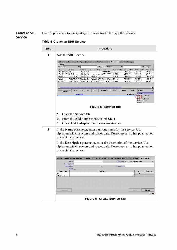
Create an SDH Service
Use this procedure to transport synchronous traffic through the network.
Table 4 Create an SDH Service
Step Procedure
1 Add the SDH service.
Figure 5 Service Tab
a. Click the Service tab.
b. From the Add button menu, select SDH.
c. Click Add to display the Create Service tab.
2 In the Name parameter, enter a unique name for the service. Use alphanumeric characters and spaces only. Do not use any other punctuation or special characters.
In the Description parameter, enter the description of the service. Use alphanumeric characters and spaces only. Do not use any other punctuation or special characters.
Figure 6 Create Service Tab
8 TransNav Provisioning Guide, Release TN5.0.x
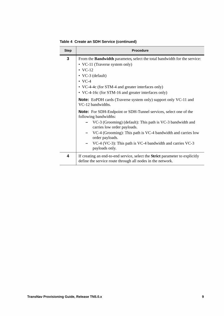
3 From the Bandwidth parameter, select the total bandwidth for the service: • VC-11 (Traverse system only)• VC-12• VC-3 (default)• VC-4• VC-4-4c (for STM-4 and greater interfaces only)• VC-4-16c (for STM-16 and greater interfaces only)
Note: EoPDH cards (Traverse system only) support only VC-11 and VC-12 bandwidths.
Note: For SDH-Endpoint or SDH-Tunnel services, select one of the following bandwidths:
– VC-3 (Grooming) (default): This path is VC-3 bandwidth and carries low order payloads.
– VC-4 (Grooming): This path is VC-4 bandwidth and carries low order payloads.
– VC-4 (VC-3): This path is VC-4 bandwidth and carries VC-3 payloads only.
4 If creating an end-to-end service, select the Strict parameter to explicitly define the service route through all nodes in the network.
Table 4 Create an SDH Service (continued)
Step Procedure
TransNav Provisioning Guide, Release TN5.0.x 9
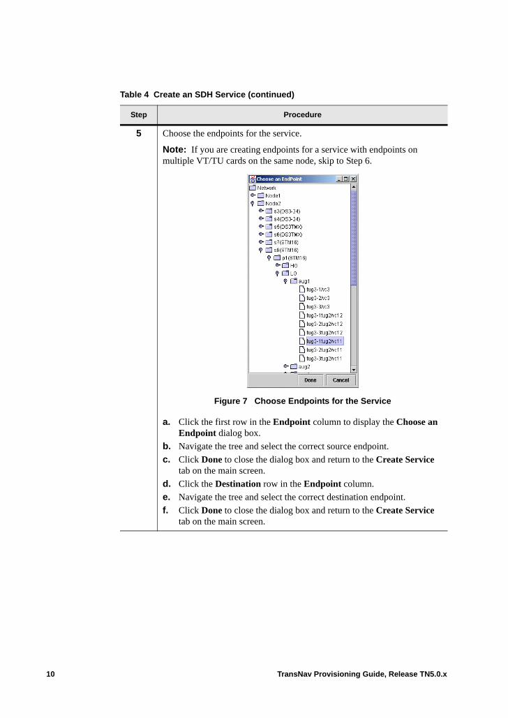
5 Choose the endpoints for the service.
Note: If you are creating endpoints for a service with endpoints on multiple VT/TU cards on the same node, skip to Step 6.
Figure 7 Choose Endpoints for the Service
a. Click the first row in the Endpoint column to display the Choose an Endpoint dialog box.
b. Navigate the tree and select the correct source endpoint.
c. Click Done to close the dialog box and return to the Create Service tab on the main screen.
d. Click the Destination row in the Endpoint column.
e. Navigate the tree and select the correct destination endpoint.
f. Click Done to close the dialog box and return to the Create Service tab on the main screen.
Table 4 Create an SDH Service (continued)
Step Procedure
10 TransNav Provisioning Guide, Release TN5.0.x

6 Configure the protection attributes for this service. Click the Protection field to display the Protection dialog box.
Figure 8 Protection Dialog Box
In the Protection Type parameter, select one of the following options: • Unprotected (default): For services that are either unprotected, 1+1
APS/MSP protected, protected with an equipment protection group, or a 1+1 Path Protection group.
• Any: The system finds the best effort of protection through the network. There may be some spans of unprotected links, but the system will create the service.
• Full: The system only creates the service if there is full protection on every transport link in the network.
• 1+1 Path Protected: If this service is protected by another service (two services model).
• UPSR Ingress: If the service is a LO VC service and is creating a bi-directional path across two interconnected SNCP rings.
7 For services that have a protection type configured, configure the following parameters:• Revertive (default is not selected): Select the check box to switch traffic
back to the original path once the failure condition no longer exists.• WTR Time (default is 5): Specifies the amount of time (in minutes) for
the system to wait before restoring traffic to the original path once the failure condition no longer exists. Specify a value between 1 and 60 minutes.
If this service is protected by a BLSR or an MS-SPRing, go to Step 8.
If this service is protected by another service (two services path protection model), go to Step 9.
Table 4 Create an SDH Service (continued)
Step Procedure
TransNav Provisioning Guide, Release TN5.0.x 11

8 If the endpoints of the service are on a BLSR or MS-SPRing, click the MSSP/BLSR tab and configure the following parameters: • Ring Source Node ID: Select the BLSR Node ID where the traffic on
this path enters the ring.• Ring Destination Node ID: Select the BLSR Node ID where the traffic
on this path exits the ring.
9 For services protected by another service, click the 1+1 Path Protected tab and configure the HoldOffTimer parameter. This parameter applies only if there is also a 1+1 APS/MSP protection group. Allows line protection to switch first before the path switches. If the line switches within the specified time period, the path does not switch. The hold-off timer starts when path protection detects a path failure.
The range is 0 to 1000 ms. The default is 0 indicating that path protection performs protection switching immediately.
10 On the Protection dialog box, click Done to return to the Create Service tab on the main screen.
11 On the Create Service tab, click Advanced to configure more parameters of the service.
Figure 9 Advanced Parameters Dialog Box
For specific definitions of these parameters, see Chapter 26—“Common Procedures for Services,” Configure Advanced Parameters (Alphabetic Order).
To provision a VT-MUX service, continue to Step 12.
To complete the service, skip to Step 13.
Table 4 Create an SDH Service (continued)
Step Procedure
12 TransNav Provisioning Guide, Release TN5.0.x
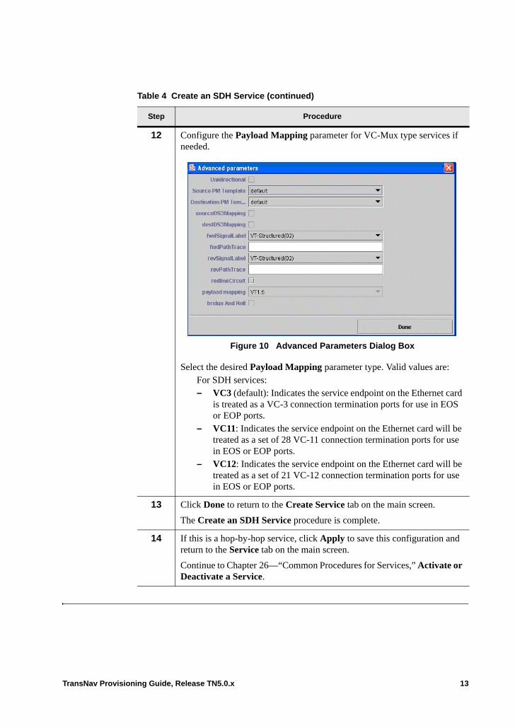
12 Configure the Payload Mapping parameter for VC-Mux type services if needed.
Figure 10 Advanced Parameters Dialog Box
Select the desired Payload Mapping parameter type. Valid values are: For SDH services:– VC3 (default): Indicates the service endpoint on the Ethernet card
is treated as a VC-3 connection termination ports for use in EOS or EOP ports.
– VC11: Indicates the service endpoint on the Ethernet card will be treated as a set of 28 VC-11 connection termination ports for use in EOS or EOP ports.
– VC12: Indicates the service endpoint on the Ethernet card will be treated as a set of 21 VC-12 connection termination ports for use in EOS or EOP ports.
13 Click Done to return to the Create Service tab on the main screen.
The Create an SDH Service procedure is complete.
14 If this is a hop-by-hop service, click Apply to save this configuration and return to the Service tab on the main screen.
Continue to Chapter 26—“Common Procedures for Services,” Activate or Deactivate a Service.
Table 4 Create an SDH Service (continued)
Step Procedure
TransNav Provisioning Guide, Release TN5.0.x 13
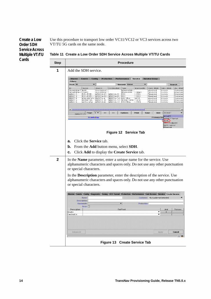
Create a Low Order SDH Service Across Multiple VT/TU Cards
Use this procedure to transport low order VC11/VC12 or VC3 services across two VT/TU 5G cards on the same node.
Table 11 Create a Low Order SDH Service Across Multiple VT/TU Cards
Step Procedure
1 Add the SDH service.
Figure 12 Service Tab
a. Click the Service tab.
b. From the Add button menu, select SDH.
c. Click Add to display the Create Service tab.
2 In the Name parameter, enter a unique name for the service. Use alphanumeric characters and spaces only. Do not use any other punctuation or special characters.
In the Description parameter, enter the description of the service. Use alphanumeric characters and spaces only. Do not use any other punctuation or special characters.
Figure 13 Create Service Tab
14 TransNav Provisioning Guide, Release TN5.0.x
3 From the Bandwidth parameter, select the total bandwidth for the service: • VC-11 (Traverse system only)• VC-12• VC-3 (default)• VC-4• VC-4-4c (for STM-4 and greater interfaces only)• VC-4-16c (for STM-16 and greater interfaces only)
Note: EoPDH cards (Traverse system only) support only VC-11 and VC-12 bandwidths.
Note: For SDH-Endpoint or SDH-Tunnel services, select one of the following bandwidths:
– VC-3 (Grooming) (default): This path is VC-3 bandwidth and carries low order payloads.
– VC-4 (Grooming): This path is VC-4 bandwidth and carries low order payloads.
– VC-4 (VC-3): This path is VC-4 bandwidth and carries VC-3 payloads only.
4 If creating an end-to-end service, select the Strict parameter to explicitly define the service route through all nodes in the network.
Table 11 Create a Low Order SDH Service Across Multiple VT/TU Cards
Step Procedure
TransNav Provisioning Guide, Release TN5.0.x 15
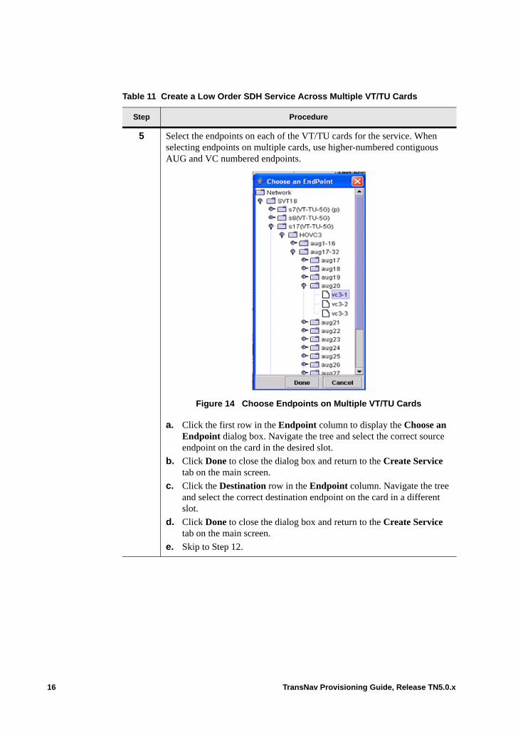
5 Select the endpoints on each of the VT/TU cards for the service. When selecting endpoints on multiple cards, use higher-numbered contiguous AUG and VC numbered endpoints.
Figure 14 Choose Endpoints on Multiple VT/TU Cards
a. Click the first row in the Endpoint column to display the Choose an Endpoint dialog box. Navigate the tree and select the correct source endpoint on the card in the desired slot.
b. Click Done to close the dialog box and return to the Create Service tab on the main screen.
c. Click the Destination row in the Endpoint column. Navigate the tree and select the correct destination endpoint on the card in a different slot.
d. Click Done to close the dialog box and return to the Create Service tab on the main screen.
e. Skip to Step 12.
Table 11 Create a Low Order SDH Service Across Multiple VT/TU Cards
Step Procedure
16 TransNav Provisioning Guide, Release TN5.0.x
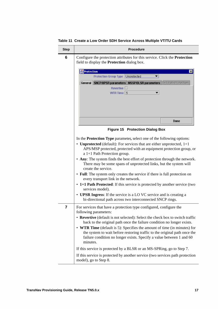
6 Configure the protection attributes for this service. Click the Protection field to display the Protection dialog box.
Figure 15 Protection Dialog Box
In the Protection Type parameter, select one of the following options: • Unprotected (default): For services that are either unprotected, 1+1
APS/MSP protected, protected with an equipment protection group, or a 1+1 Path Protection group.
• Any: The system finds the best effort of protection through the network. There may be some spans of unprotected links, but the system will create the service.
• Full: The system only creates the service if there is full protection on every transport link in the network.
• 1+1 Path Protected: If this service is protected by another service (two services model).
• UPSR Ingress: If the service is a LO VC service and is creating a bi-directional path across two interconnected SNCP rings.
7 For services that have a protection type configured, configure the following parameters:• Revertive (default is not selected): Select the check box to switch traffic
back to the original path once the failure condition no longer exists.• WTR Time (default is 5): Specifies the amount of time (in minutes) for
the system to wait before restoring traffic to the original path once the failure condition no longer exists. Specify a value between 1 and 60 minutes.
If this service is protected by a BLSR or an MS-SPRing, go to Step 7.
If this service is protected by another service (two services path protection model), go to Step 8.
Table 11 Create a Low Order SDH Service Across Multiple VT/TU Cards
Step Procedure
TransNav Provisioning Guide, Release TN5.0.x 17
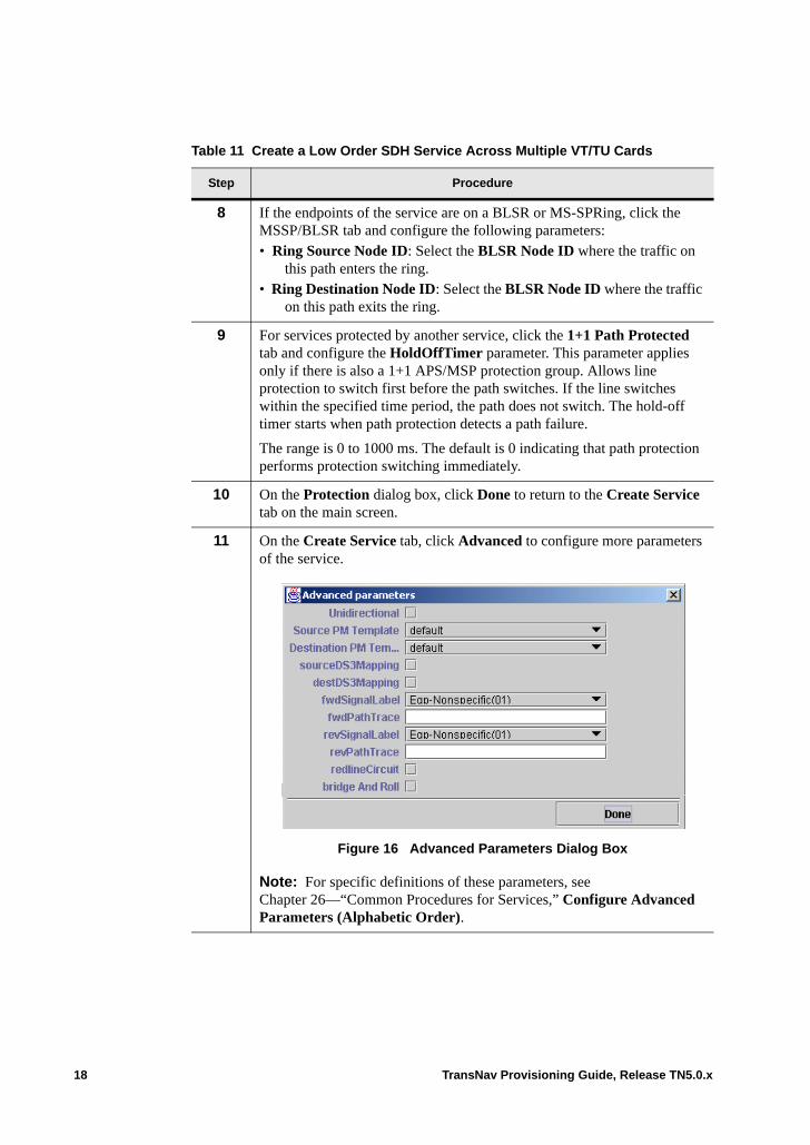
8 If the endpoints of the service are on a BLSR or MS-SPRing, click the MSSP/BLSR tab and configure the following parameters: • Ring Source Node ID: Select the BLSR Node ID where the traffic on
this path enters the ring.• Ring Destination Node ID: Select the BLSR Node ID where the traffic
on this path exits the ring.
9 For services protected by another service, click the 1+1 Path Protected tab and configure the HoldOffTimer parameter. This parameter applies only if there is also a 1+1 APS/MSP protection group. Allows line protection to switch first before the path switches. If the line switches within the specified time period, the path does not switch. The hold-off timer starts when path protection detects a path failure.
The range is 0 to 1000 ms. The default is 0 indicating that path protection performs protection switching immediately.
10 On the Protection dialog box, click Done to return to the Create Service tab on the main screen.
11 On the Create Service tab, click Advanced to configure more parameters of the service.
Figure 16 Advanced Parameters Dialog Box
Note: For specific definitions of these parameters, see Chapter 26—“Common Procedures for Services,” Configure Advanced Parameters (Alphabetic Order).
Table 11 Create a Low Order SDH Service Across Multiple VT/TU Cards
Step Procedure
18 TransNav Provisioning Guide, Release TN5.0.x
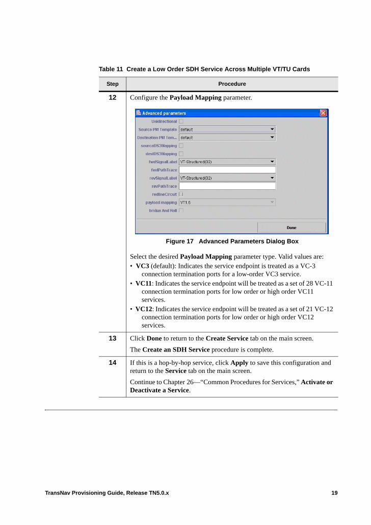
12 Configure the Payload Mapping parameter.
Figure 17 Advanced Parameters Dialog Box
Select the desired Payload Mapping parameter type. Valid values are: • VC3 (default): Indicates the service endpoint is treated as a VC-3
connection termination ports for a low-order VC3 service.• VC11: Indicates the service endpoint will be treated as a set of 28 VC-11
connection termination ports for low order or high order VC11 services.
• VC12: Indicates the service endpoint will be treated as a set of 21 VC-12 connection termination ports for low order or high order VC12 services.
13 Click Done to return to the Create Service tab on the main screen.
The Create an SDH Service procedure is complete.
14 If this is a hop-by-hop service, click Apply to save this configuration and return to the Service tab on the main screen.
Continue to Chapter 26—“Common Procedures for Services,” Activate or Deactivate a Service.
Table 11 Create a Low Order SDH Service Across Multiple VT/TU Cards
Step Procedure
TransNav Provisioning Guide, Release TN5.0.x 19

Create an SDH Endpoint or Tunnel Service
Use an SDH Endpoint service to create termination points to multiplex low order traffic into the network or to create a transport path through the Traverse network (for TE-100s, the transport path must be created hop-by-hop).
Use an SDH Tunnel Service to create a transport path end-to-end through the network. The endpoints for an SDH Tunnel are the transport cards at the add and drop nodes.
Table 18 Create an SDH Endpoint or SDH Tunnel Service
Step Procedure
1 Add the SDH Endpoint or SDH Tunnel service.
Figure 19 Service Tab
a. Click the Service tab.
b. From the Add button menu, select SDH Endpoint or SDH Tunnel.
c. Click Add to display the Create Service tab.
20 TransNav Provisioning Guide, Release TN5.0.x

2 In the Name field, enter a unique name for the service. Use alphanumeric characters and spaces only. Do not use any other punctuation or special characters.
Figure 20 Create Service Tab
3 From the Bandwidth parameter, select the total bandwidth for the service: • VC-3 (Grooming) (default): This path is VC-3 bandwidth and carries
low order payloads.• VC-4 (Grooming): This path is VC-4 bandwidth and carries low order
payloads.• VC-4 (VC-3): This path is VC-4 bandwidth and carries VC-3 payloads
only.
4 Choose the endpoints for the service. For Traverse services, refer to the VT/TU 5G Switch Card SDH Guidelines as required.
For information on endpoint requirements, see Chapter 56—“Service Endpoints.”
a. Click the first row in the Endpoint column to display the Choose an Endpoint dialog box.
b. Navigate the tree and select the correct source endpoint.On the Traverse system, if the Bandwidth is (Grooming), make sure to select the correct VCX or VT/TU 5G Switch card.
c. Click Done to close the dialog box and return to the Create Service tab on the main screen.
d. Click the Destination row in the Endpoint column.
e. Navigate the tree and select the correct destination endpoint.
f. Click Done to close the dialog box and return to the Create Service tab on the main screen.
Table 18 Create an SDH Endpoint or SDH Tunnel Service (continued)
Step Procedure
TransNav Provisioning Guide, Release TN5.0.x 21
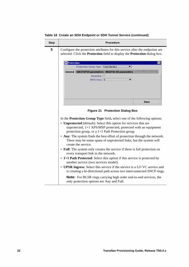
5 Configure the protection attributes for this service after the endpoints are selected. Click the Protection field to display the Protection dialog box.
Figure 21 Protection Dialog Box
In the Protection Group Type field, select one of the following options: • Unprotected (default): Select this option for services that are
unprotected, 1+1 APS/MSP protected, protected with an equipment protection group, or a 1+1 Path Protection group.
• Any: The system finds the best effort of protection through the network. There may be some spans of unprotected links, but the system will create the service.
• Full: The system only creates the service if there is full protection on every transport link in the network.
• 1+1 Path Protected: Select this option if this service is protected by another service (two services model).
• UPSR Ingress: Select this service if the service is a LO VC service and is creating a bi-directional path across two interconnected SNCP rings.
Note: For BLSR rings carrying high order end-to-end services, the only protection options are Any and Full.
Table 18 Create an SDH Endpoint or SDH Tunnel Service (continued)
Step Procedure
22 TransNav Provisioning Guide, Release TN5.0.x
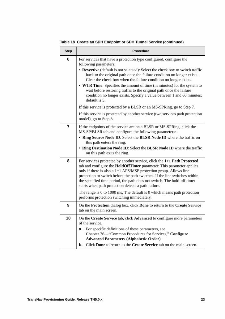
6 For services that have a protection type configured, configure the following parameters:• Revertive (default is not selected): Select the check box to switch traffic
back to the original path once the failure condition no longer exists. Clear the check box when the failure condition no longer exists.
• WTR Time: Specifies the amount of time (in minutes) for the system to wait before restoring traffic to the original path once the failure condition no longer exists. Specify a value between 1 and 60 minutes; default is 5.
If this service is protected by a BLSR or an MS-SPRing, go to Step 7.
If this service is protected by another service (two services path protection model), go to Step 8.
7 If the endpoints of the service are on a BLSR or MS-SPRing, click the MS-SP/BLSR tab and configure the following parameters: • Ring Source Node ID: Select the BLSR Node ID where the traffic on
this path enters the ring.• Ring Destination Node ID: Select the BLSR Node ID where the traffic
on this path exits the ring.
8 For services protected by another service, click the 1+1 Path Protected tab and configure the HoldOffTimer parameter. This parameter applies only if there is also a 1+1 APS/MSP protection group. Allows line protection to switch before the path switches. If the line switches within the specified time period, the path does not switch. The hold-off timer starts when path protection detects a path failure.
The range is 0 to 1000 ms. The default is 0 which means path protection performs protection switching immediately.
9 On the Protection dialog box, click Done to return to the Create Service tab on the main screen.
10 On the Create Service tab, click Advanced to configure more parameters of the service.
a. For specific definitions of these parameters, see Chapter 26—“Common Procedures for Services,” Configure Advanced Parameters (Alphabetic Order).
b. Click Done to return to the Create Service tab on the main screen.
Table 18 Create an SDH Endpoint or SDH Tunnel Service (continued)
Step Procedure
TransNav Provisioning Guide, Release TN5.0.x 23
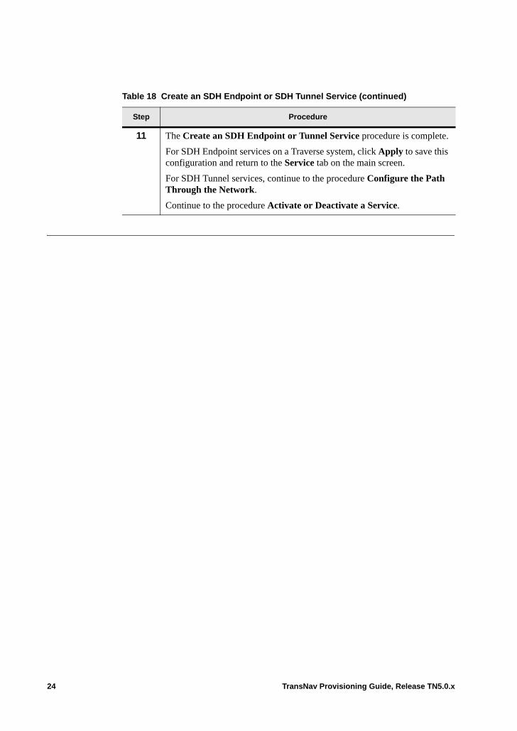
11 The Create an SDH Endpoint or Tunnel Service procedure is complete.
For SDH Endpoint services on a Traverse system, click Apply to save this configuration and return to the Service tab on the main screen.
For SDH Tunnel services, continue to the procedure Configure the Path Through the Network.
Continue to the procedure Activate or Deactivate a Service.
Table 18 Create an SDH Endpoint or SDH Tunnel Service (continued)
Step Procedure
24 TransNav Provisioning Guide, Release TN5.0.x
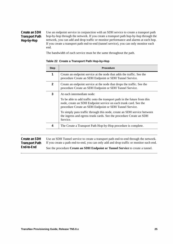
Create an SDH Transport Path Hop-by-Hop
Use an endpoint service in conjunction with an SDH service to create a transport path hop-by-hop through the network. If you create a transport path hop-by-hop through the network, you can add and drop traffic or monitor performance and alarms at each hop. If you create a transport path end-to-end (tunnel service), you can only monitor each end.
The bandwidth of each service must be the same throughout the path.
Create an SDH Transport Path End-to-End
Use an SDH Tunnel service to create a transport path end-to-end through the network. If you create a path end-to-end, you can only add and drop traffic or monitor each end.
See the procedure Create an SDH Endpoint or Tunnel Service to create a tunnel.
Table 22 Create a Transport Path Hop-by-Hop
Step Procedure
1 Create an endpoint service at the node that adds the traffic. See the procedure Create an SDH Endpoint or SDH Tunnel Service.
2 Create an endpoint service at the node that drops the traffic. See the procedure Create an SDH Endpoint or SDH Tunnel Service.
3 At each intermediate node:
To be able to add traffic onto the transport path in the future from this node, create an SDH Endpoint service on each trunk card. See the procedure Create an SDH Endpoint or SDH Tunnel Service.
To simply pass traffic through this node, create an SDH service between the ingress and egress trunk cards. See the procedure Create an SDH Service.
4 The Create a Transport Path Hop-by-Hop procedure is complete.
TransNav Provisioning Guide, Release TN5.0.x 25

26 TransNav Provisioning Guide, Release TN5.0.x

Chapter 30 Creating 2-Port OC-48/STM-16 Services
Introduction The Traverse platform distributed switching architecture allows each card (module) a bi-directional switching capacity of up to 2.5 Gbps between each individual slot. This means each slot can switch up to 2.5 Gbps of traffic bi-directionally between any slot and any slot.
The following topics explain how to create bi-directional switching capacity between slots:• Slot-to-Slot Switching Capacity• Guidelines to Provision Protected Services• Protection Groups using the 2-port OC-48/STM-16 Card• Protected Services from a 2-port OC-48/STM-16 to a Protected OC-192/ STM-64
Uplink• Aggregated Services from OC-48 UPSRs to OC-192 Uplinks• Guidelines to Create an Aggregate Service from a Subtended OC-48 UPSR
TransNav Provisioning Guide, Release TN5.0.x 1
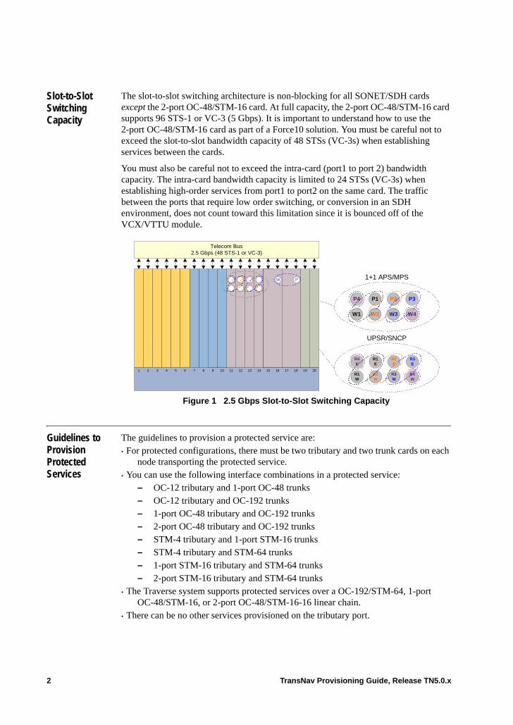
Slot-to-Slot Switching Capacity
The slot-to-slot switching architecture is non-blocking for all SONET/SDH cards except the 2-port OC-48/STM-16 card. At full capacity, the 2-port OC-48/STM-16 card supports 96 STS-1 or VC-3 (5 Gbps). It is important to understand how to use the 2-port OC-48/STM-16 card as part of a Force10 solution. You must be careful not to exceed the slot-to-slot bandwidth capacity of 48 STSs (VC-3s) when establishing services between the cards.
You must also be careful not to exceed the intra-card (port1 to port 2) bandwidth capacity. The intra-card bandwidth capacity is limited to 24 STSs (VC-3s) when establishing high-order services from port1 to port2 on the same card. The traffic between the ports that require low order switching, or conversion in an SDH environment, does not count toward this limitation since it is bounced off of the VCX/VTTU module.
Figure 1 2.5 Gbps Slot-to-Slot Switching Capacity
Guidelines to Provision Protected Services
The guidelines to provision a protected service are:• For protected configurations, there must be two tributary and two trunk cards on each
node transporting the protected service.• You can use the following interface combinations in a protected service:
– OC-12 tributary and 1-port OC-48 trunks– OC-12 tributary and OC-192 trunks– 1-port OC-48 tributary and OC-192 trunks– 2-port OC-48 tributary and OC-192 trunks– STM-4 tributary and 1-port STM-16 trunks– STM-4 tributary and STM-64 trunks– 1-port STM-16 tributary and STM-64 trunks– 2-port STM-16 tributary and STM-64 trunks
• The Traverse system supports protected services over a OC-192/STM-64, 1-port OC-48/STM-16, or 2-port OC-48/STM-16-16 linear chain.
• There can be no other services provisioned on the tributary port.
P1P4 P2 P3
W1 W2 W3 W4
R1E
R4E
R2E
R3E
R1W
R2W
R3W
R4W
1+1 APS/MPS
UPSR/SNCP
1 2 3 4 5 6 7 8 9 10 11 12 13 14 15 16 17 18 19 20
W P
Telecom Bus2.5 Gbps (48 STS-1 or VC-3)
2 TransNav Provisioning Guide, Release TN5.0.x
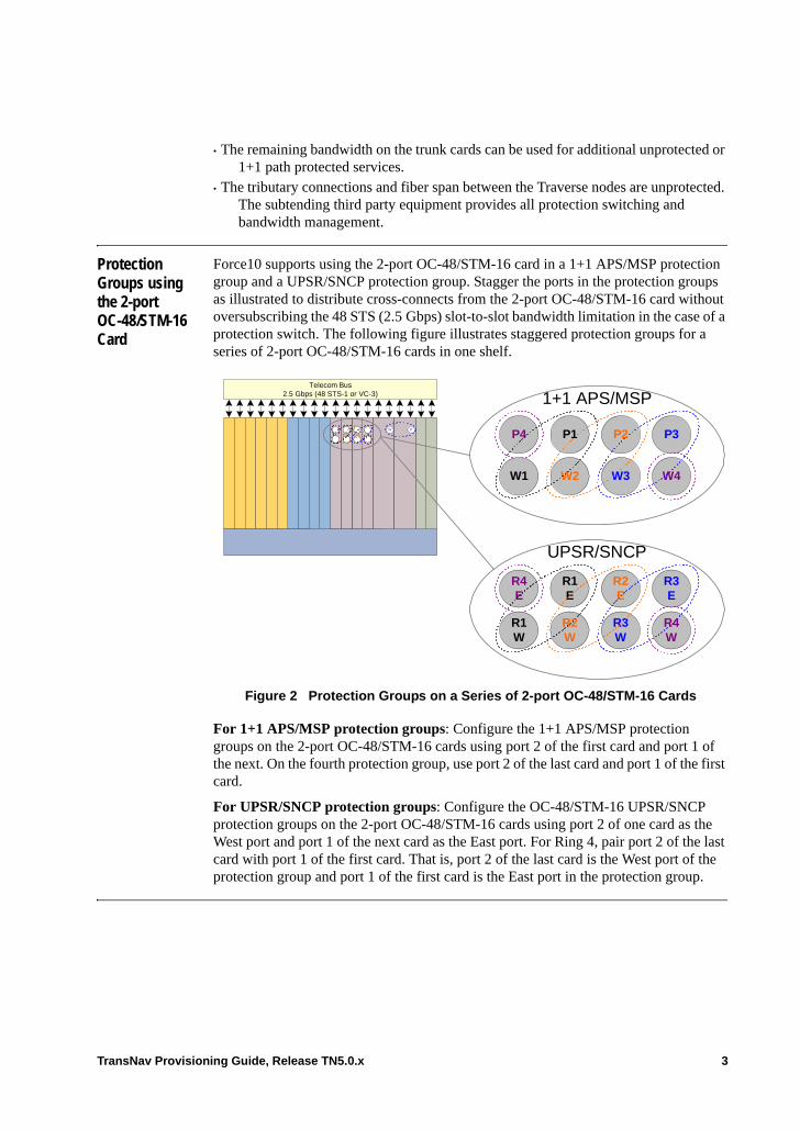
• The remaining bandwidth on the trunk cards can be used for additional unprotected or 1+1 path protected services.
• The tributary connections and fiber span between the Traverse nodes are unprotected. The subtending third party equipment provides all protection switching and bandwidth management.
Protection Groups using the 2-port OC-48/STM-16 Card
Force10 supports using the 2-port OC-48/STM-16 card in a 1+1 APS/MSP protection group and a UPSR/SNCP protection group. Stagger the ports in the protection groups as illustrated to distribute cross-connects from the 2-port OC-48/STM-16 card without oversubscribing the 48 STS (2.5 Gbps) slot-to-slot bandwidth limitation in the case of a protection switch. The following figure illustrates staggered protection groups for a series of 2-port OC-48/STM-16 cards in one shelf.
Figure 2 Protection Groups on a Series of 2-port OC-48/STM-16 Cards
For 1+1 APS/MSP protection groups: Configure the 1+1 APS/MSP protection groups on the 2-port OC-48/STM-16 cards using port 2 of the first card and port 1 of the next. On the fourth protection group, use port 2 of the last card and port 1 of the first card.
For UPSR/SNCP protection groups: Configure the OC-48/STM-16 UPSR/SNCP protection groups on the 2-port OC-48/STM-16 cards using port 2 of one card as the West port and port 1 of the next card as the East port. For Ring 4, pair port 2 of the last card with port 1 of the first card. That is, port 2 of the last card is the West port of the protection group and port 1 of the first card is the East port in the protection group.
W P
Telecom Bus2.5 Gbps (48 STS-1 or VC-3) 1+1 APS/MSP
UPSR/SNCP
P3
W4
P2
W3
P1
W2
P4
W1
R3E
R4W
R2E
R3W
R1E
R2W
R4E
R1W
TransNav Provisioning Guide, Release TN5.0.x 3
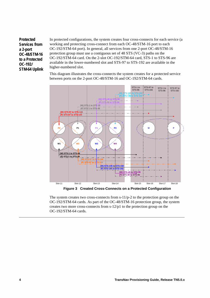
Protected Services from a 2-port OC-48/STM-16 to a Protected OC-192/ STM-64 Uplink
In protected configurations, the system creates four cross-connects for each service (a working and protecting cross-connect from each OC-48/STM-16 port to each OC-192/STM-64 port). In general, all services from one 2-port OC-48/STM-16 protection group must use a contiguous set of 48 STS (VC-3) paths on the OC-192/STM-64 card. On the 2-slot OC-192/STM-64 card, STS-1 to STS-96 are available in the lower-numbered slot and STS-97 to STS-192 are available in the higher-numbered slot.
This diagram illustrates the cross-connects the system creates for a protected service between ports on the 2-port OC-48/STM-16 and OC-192/STM-64 cards.
Figure 3 Created Cross-Connects on a Protected Configuration
The system creates two cross-connects from s-11/p-2 to the protection group on the OC-192/STM-64 cards. As part of the OC-48/STM-16 protection group, the system creates two more cross-connects from s-12/p1 to the protection group on the OC-192/STM-64 cards.
P2
W1
P1
W2
P4
W3
P3
W4
W P
(W) STS-49 to STS-96
(P) STS-97 to STS-144
(W) STS-145 to STS-192
(W) STS-1 to STS-48
(P) STS-1 to STS-48(W) STS-97 to STS-144
(P) STS-49 to STS-96
(P) STS-145 to STS-192
STS-1 toSTS-96
STS-97 toSTS-192
STS-1 toSTS-96
STS-97 toSTS-192
(W) STS-97 to STS-144(P) STS-97 to STS-144
(W) STS-1 to STS-48
(P) STS-1 to STS-48
(P) STS-49 to STS-96
(W) STS-49 to STS-96
(W) STS-145 to STS-192(P) STS-145 to STS-192
Slot-11 Slot-12 Slot-13 Slot-14 Slot-15 Slot-16 Slot-17 Slot-18
4 TransNav Provisioning Guide, Release TN5.0.x
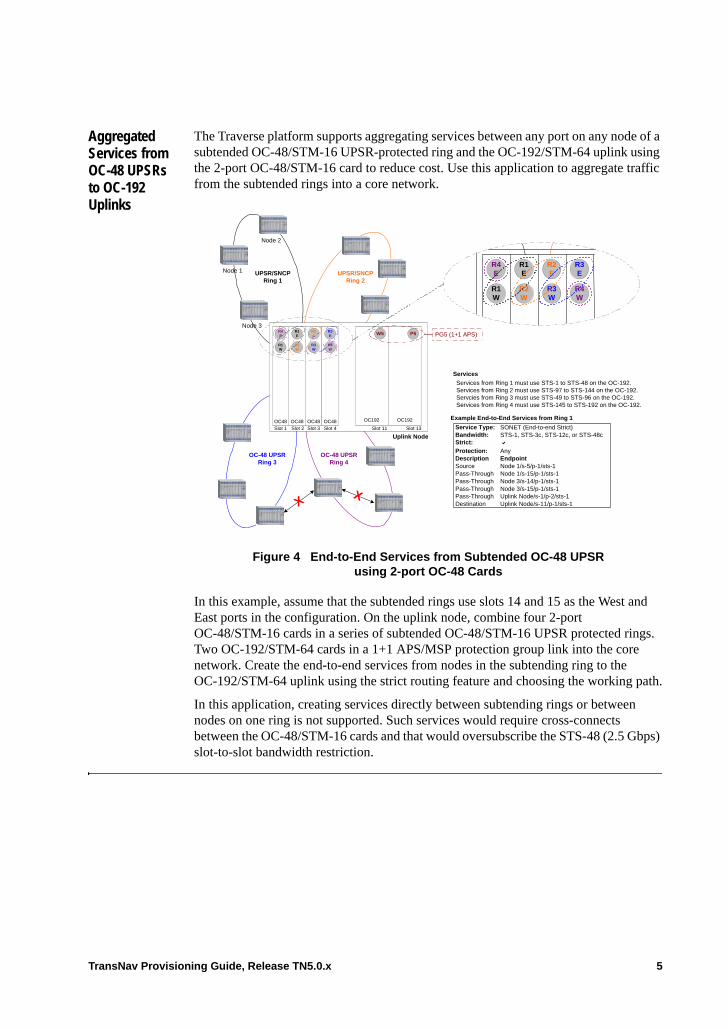
Aggregated Services from OC-48 UPSRs to OC-192 Uplinks
The Traverse platform supports aggregating services between any port on any node of a subtended OC-48/STM-16 UPSR-protected ring and the OC-192/STM-64 uplink using the 2-port OC-48/STM-16 card to reduce cost. Use this application to aggregate traffic from the subtended rings into a core network.
Figure 4 End-to-End Services from Subtended OC-48 UPSR using 2-port OC-48 Cards
In this example, assume that the subtended rings use slots 14 and 15 as the West and East ports in the configuration. On the uplink node, combine four 2-port OC-48/STM-16 cards in a series of subtended OC-48/STM-16 UPSR protected rings. Two OC-192/STM-64 cards in a 1+1 APS/MSP protection group link into the core network. Create the end-to-end services from nodes in the subtending ring to the OC-192/STM-64 uplink using the strict routing feature and choosing the working path.
In this application, creating services directly between subtending rings or between nodes on one ring is not supported. Such services would require cross-connects between the OC-48/STM-16 cards and that would oversubscribe the STS-48 (2.5 Gbps) slot-to-slot bandwidth restriction.
Slot 1
OC48
R1E
OC48
R4E
OC48
R2E
OC48
R3E
Slot 2 Slot 3 Slot 4
OC192
W5
OC192
P5
R1W
R2W
R3W
R4W
Slot 11 Slot 13
Services
PG5 (1+1 APS)
UPSR/SNCPRing 1
UPSR/SNCPRing 2
OC-48 UPSRRing 3
OC-48 UPSRRing 4
Uplink Node
Services from Ring 1 must use STS-1 to STS-48 on the OC-192.Services from Ring 2 must use STS-97 to STS-144 on the OC-192.Servcies from Ring 3 must use STS-49 to STS-96 on the OC-192.Services from Ring 4 must use STS-145 to STS-192 on the OC-192.
Example End-to-End Services from Ring 1
R1E
R4E
R2E
R3E
R1W
R2W
R3W
R4W
Node 1
Node 3
Node 2
XX
Service Type: SONET (End-to-end Strict)Bandwidth: STS-1, STS-3c, STS-12c, or STS-48cStrict:
Protection: AnyDescription EndpointSource Node 1/s-5/p-1/sts-1Pass-Through Node 1/s-15/p-1/sts-1Pass-Through Node 3/s-14/p-1/sts-1Pass-Through Node 3/s-15/p-1/sts-1Pass-Through Uplink Node/s-1/p-2/sts-1Destination Uplink Node/s-11/p-1/sts-1
TransNav Provisioning Guide, Release TN5.0.x 5
Guidelines to Create an Aggregate Service from a Subtended OC-48 UPSR
Subtended UPSR protected rings. On the uplink node, configure the OC-48/STM-16 UPSR protection groups on the 2-port OC-48/STM-16 cards using port 2 of one card as the West port and port 1 of the next card as the East port. For Ring 4, pair port 2 of the last card with port 1 of the first card. That is, port 2 of the last card is the West port of the protection group and port 1 of the first card is the East port in the protection group.
Stagger the protection groups as described to distribute the cross-connects from the 2-port OC-48/STM-16 card to the 2-slot OC-192/STM-64 card without oversubscribing the 48 STS (2.5 Gbps) slot-to-slot bandwidth limitation. In this protected configuration, the system creates four cross-connects (one from each direction in the ring to each OC-192/STM-64 port).
OC-192 Card. On the 2-slot OC-192 card, STS-1 to STS-96 are available in the lower-numbered slot. STS-97 to STS-192 are available in the higher-numbered slot. In general, all services from one OC-48/STM-16 ring must use a contiguous set of 48 STS paths on the OC-192/STM-64 card. With these references in mind, configure services from each ring with the following guidelines:• Services from Ring 1 must use STS-1 to STS-48 on the OC-192/STM-64 card• Services from Ring 2 must use STS-97 to STS-144 on the OC-192/STM-64 card• Services from Ring 3 must use STS-49 to STS-96 on the OC-192/STM-64 card• Services from Ring 4 must use STS-145 to STS-192 on the OC-192/STM-64 card
The following services are not supported. Each would require bandwidth between the 2-port OC-48/STM-16 cards that would essentially oversubscribe the STS-48 (2.5 Gbps) slot-to-slot bandwidth restriction.• Services between rings are not supported• Services between nodes on one ring are not supported
Activate the services in the following order:
1. Services from Ring 1: STS-1 to STS-48
2. Services from Ring 2: STS-97 to STS-144
3. Services from Ring 4: STS-145 to STS-192
4. Services from Ring 3: STS-49 to STS-96
6 TransNav Provisioning Guide, Release TN5.0.x
Chapter 31 Creating 1+1 Path Protected Services
Introduction 1+1 path protected services protect the entire path of one service through a network. This feature is designed to protect paths in a mesh network. You can also use 1+1 path protection to protect traffic traveling over unprotected facilities.
This chapter explains how to create 1+1 path protection groups and 1+1 path protected services through a Traverse network. Only the Traverse system supports 1+1 path protection groups.• Path Protection Group Model (SONET)• Path Protection Group Model (SDH)• High Order Services with Path Protection• Low Order Services with Path Protection• Path Protection over APS-Protected Links• Path Protection over MSP-Protected Links• Before You Create 1+1 Path Protected Services• Guidelines to Provision 1+1 Path Protected Services• Procedures Required to Create a 1+1 Path Protected Service• Bookend Application• Guidelines to Create a Bookend Application• Procedures Required to Create a Bookend Application• Before You Create a 1+1 Path Protection Group• Guidelines to Create a 1+1 Path Protection Group• Create a 1+1 Path Protection Group
If your system includes 2-port OC-48 or STM-16 cards, see Chapter 30—“Creating 2-Port OC-48/STM-16 Services” for additional information.
TransNav Provisioning Guide, Release TN5.0.x 1
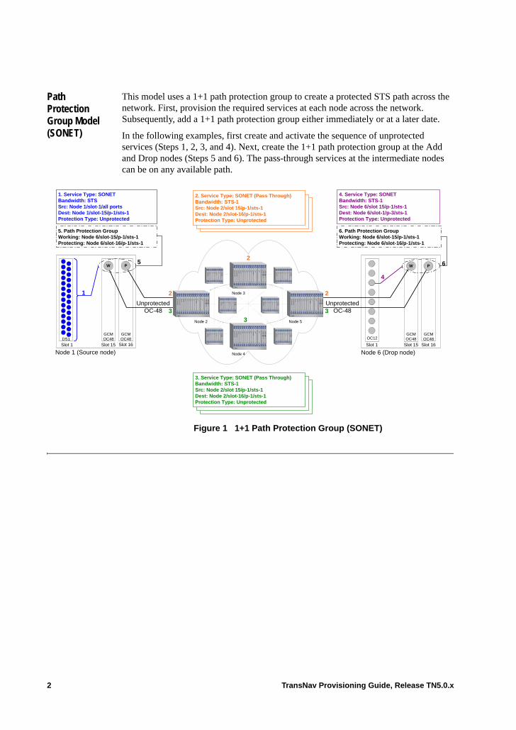
Path Protection Group Model (SONET)
This model uses a 1+1 path protection group to create a protected STS path across the network. First, provision the required services at each node across the network. Subsequently, add a 1+1 path protection group either immediately or at a later date.
In the following examples, first create and activate the sequence of unprotected services (Steps 1, 2, 3, and 4). Next, create the 1+1 path protection group at the Add and Drop nodes (Steps 5 and 6). The pass-through services at the intermediate nodes can be on any available path.
Figure 1 1+1 Path Protection Group (SONET)
Node 1 (Source node)Slot 1
GCMOC48
Slot 16
GCMOC48
Slot 15
1. Service Type: SONETBandwidth: STSSrc: Node 1/slot-1/all portsDest: Node 1/slot-15/p-1/sts-1Protection Type: Unprotected
UnprotectedOC-48
Node 6 (Drop node)Slot 1
GCMOC48
Slot 16
GCMOC48
Slot 15
OC12
4. Service Type: SONETBandwidth: STS-1Src: Node 6/slot 15/p-1/sts-1Dest: Node 6/slot-1/p-3/sts-1Protection Type: Unprotected
6. Path Protection GroupWorking: Node 6/slot-15/p-1/sts-1Protecting: Node 6/slot-16/p-1/sts-1
1 2
2
2
4
5. Path Protection GroupWorking: Node 6/slot-15/p-1/sts-1Protecting: Node 6/slot-16/p-1/sts-1
Node 4
Node 3
Node 2
PW
3
3
3
Node 5
W P 6
UnprotectedOC-48
5
3. Service Type: SONET (Pass Through)Bandwidth: STS-1Src: Node 2/slot 15/p-1/sts-1Dest: Node 2/slot-16/p-1/sts-1Protection Type: Unprotected
2. Service Type: SONET (Pass Through)Bandwidth: STS-1Src: Node 2/slot 15/p-1/sts-1Dest: Node 2/slot-16/p-1/sts-1Protection Type: Unprotected
DS1
2 TransNav Provisioning Guide, Release TN5.0.x
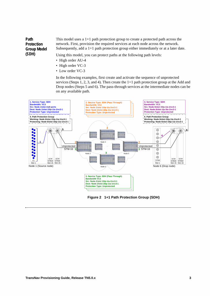
Path Protection Group Model (SDH)
This model uses a 1+1 path protection group to create a protected path across the network. First, provision the required services at each node across the network. Subsequently, add a 1+1 path protection group either immediately or at a later date.
Using this model, you can protect paths at the following path levels:• High order AU-4• High order VC-3• Low order VC-3
In the following examples, first create and activate the sequence of unprotected services (Steps 1, 2, 3, and 4). Then create the 1+1 path protection group at the Add and Drop nodes (Steps 5 and 6). The pass-through services at the intermediate nodes can be on any available path.
Figure 2 1+1 Path Protection Group (SDH)
Node 1 (Source node)Slot 1
GCMSTM16Slot 16
GCMSTM16Slot 15
1. Service Type: SDHBandwidth: VC3Src: Node 1/slot-1/all portsDest: Node 1/slot-15/p-1/a-1/vc3-1Protection Type: Unprotected
UnprotectedSTM-16
Node 6 (Drop node)Slot 1
GCMSTM16Slot 16
GCMSTM16Slot 15
STM4
4. Service Type: SDHBandwidth: VC3Src: Node 6/slot 15/p-1/a-1/vc3-1Dest: Node 6/slot-1/p-3/a-1/vc3-1Protection Type: Unprotected
6. Path Protection GroupWorking: Node 6/slot-15/p-1/a-1/vc3-1Protecting: Node 6/slot-16/p-1/a-1/vc3-1
1 2
2
2
4
5. Path Protection GroupWorking: Node 6/slot-15/p-1/a-1/vc3-1Protecting: Node 6/slot-16/p-1/a-1/vc3-1
Node 4
Node 3
Node 2
PW
3
3
3
Node 5
W P 6
UnprotectedSTM-16
5
E1
3. Service Type: SDH (Pass Through)Bandwidth VC3Src: Node 2/slot 15/p-1/a-1/vc3-1Dest: Node 2/slot-16/p-1/a-1/vc3-1Protection Type: Unprotected
2. Service Type: SDH (Pass Through)Bandwidth: VC3Src: Node 2/slot 15/p-1/a-1/vc3-1Dest: Node 2/slot-16/p-1/a-1/vc3-1Protection Type: Unprotected
TransNav Provisioning Guide, Release TN5.0.x 3
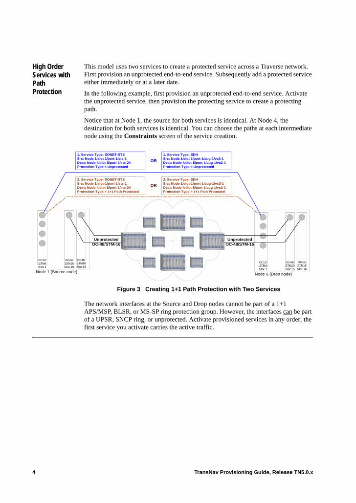
High Order Services with Path Protection
This model uses two services to create a protected service across a Traverse network. First provision an unprotected end-to-end service. Subsequently add a protected service either immediately or at a later date.
In the following example, first provision an unprotected end-to-end service. Activate the unprotected service, then provision the protecting service to create a protecting path.
Notice that at Node 1, the source for both services is identical. At Node 4, the destination for both services is identical. You can choose the paths at each intermediate node using the Constraints screen of the service creation.
Figure 3 Creating 1+1 Path Protection with Two Services
The network interfaces at the Source and Drop nodes cannot be part of a 1+1 APS/MSP, BLSR, or MS-SP ring protection group. However, the interfaces can be part of a UPSR, SNCP ring, or unprotected. Activate provisioned services in any order; the first service you activate carries the active traffic.
Node 1 (Source node)
OC12/STM4Slot 1
OC48/STM16Slot 16
OC48/STM16Slot 15
2. Service Type: SONET-STSSrc: Node 1/slot-1/port-1/sts-1Dest: Node 4/slot-8/port-1/sts-24Protection Type = 1+1 Path Protected
1. Service Type: SONET-STSSrc: Node 1/slot 1/port-1/sts-1Dest: Node 4/slot-8/port-1/sts-24Protection Type = Unprotected
Node 6 (Drop node)
UnprotectedOC-48/STM-16
UnprotectedOC-48/STM-16
2. Service Type: SDHSrc: Node 1/slot-1/port-1/aug-1/vc3-1Dest: Node 4/slot-8/port-1/aug-1/vc3-1Protection Type = 1+1 Path Protected
1. Service Type: SDHSrc: Node 1/slot 1/port-1/aug-1/vc3-1Dest: Node 4/slot-8/port-1/aug-1/vc3-1Protection Type = Unprotected
OR
OR
OC12/STM4Slot 1
OC48/STM16Slot 16
OC48/STM16Slot 15
4 TransNav Provisioning Guide, Release TN5.0.x
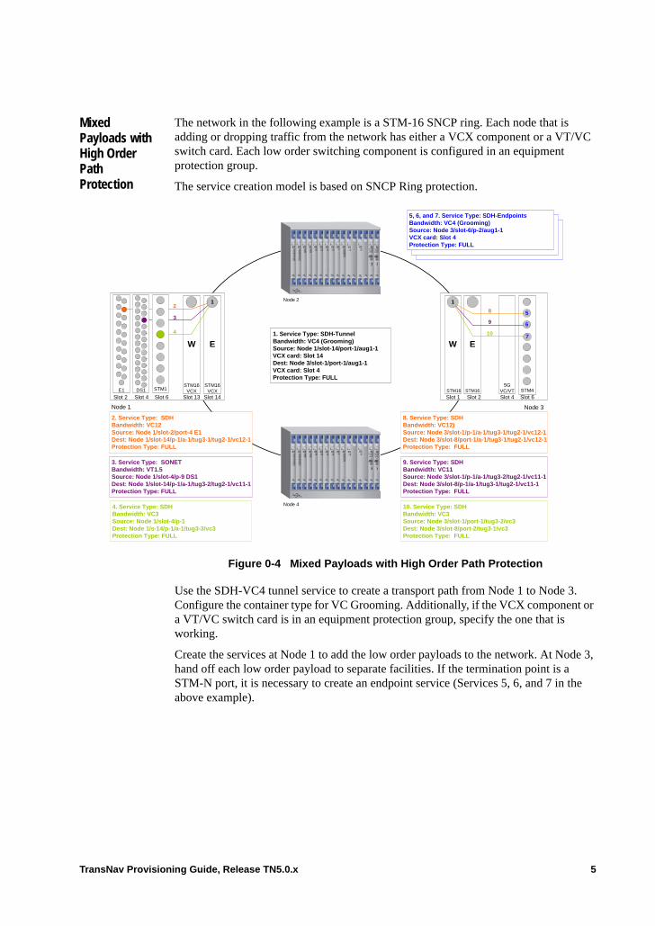
Mixed Payloads with High Order Path Protection
The network in the following example is a STM-16 SNCP ring. Each node that is adding or dropping traffic from the network has either a VCX component or a VT/VC switch card. Each low order switching component is configured in an equipment protection group.
The service creation model is based on SNCP Ring protection.
Figure 0-4 Mixed Payloads with High Order Path Protection
Use the SDH-VC4 tunnel service to create a transport path from Node 1 to Node 3. Configure the container type for VC Grooming. Additionally, if the VCX component or a VT/VC switch card is in an equipment protection group, specify the one that is working.
Create the services at Node 1 to add the low order payloads to the network. At Node 3, hand off each low order payload to separate facilities. If the termination point is a STM-N port, it is necessary to create an endpoint service (Services 5, 6, and 7 in the above example).
5GVC/VT
1. Service Type: SDH-TunnelBandwidth: VC4 (Grooming)Source: Node 1/slot-14/port-1/aug1-1VCX card: Slot 14Dest: Node 3/slot-1/port-1/aug1-1VCX card: Slot 4Protection Type: FULL
4. Service Type: SDHBandwidth: VC3Source: Node 1/slot-4/p-1Dest: Node 1/s-14/p-1/a-1/tug3-3/vc3Protection Type: FULL
Node 3
3. Service Type: SONETBandwidth: VT1.5Source: Node 1/slot-4/p-9 DS1Dest: Node 1/slot-14/p-1/a-1/tug3-2/tug2-1/vc11-1Protection Type: FULL
2. Service Type: SDHBandwidth: VC12Source: Node 1/slot-2/port-4 E1Dest: Node 1/slot-14/p-1/a-1/tug3-1/tug2-1/vc12-1Protection Type: FULL
Node 1
Slot 2 Slot 4
2
3
4
Node 2
Node 4
Slot 6E1
W E
STM16 STM16 STM4
Slot 1 Slot 2 Slot 4
1
E
STM16VCX
Slot 14
W
STM16VCX
Slot 13
STM1DS1
1
8
9
10
10. Service Type: SDHBandwidth: VC3Source: Node 3/slot-1/port-1/tug3-2/vc3Dest: Node 3/slot-8/port-2/tug3-1/vc3Protection Type: FULL
8. Service Type: SDHBandwidth: VC12)Source: Node 3/slot-1/p-1/a-1/tug3-1/tug2-1/vc12-1Dest: Node 3/slot-8/port-1/a-1/tug3-1/tug2-1/vc12-1Protection Type: FULL
9. Service Type: SDHBandwidth: VC11Source: Node 3/slot-1/p-1/a-1/tug3-2/tug2-1/vc11-1Dest: Node 3/slot-8/p-1/a-1/tug3-1/tug2-1/vc11-1Protection Type: FULL
5, 6, and 7. Service Type: SDH-EndpointsBandwidth: VC4 (Grooming)Source: Node 3/slot-6/p-2/aug1-1VCX card: Slot 4Protection Type: FULL
5
6
7
Slot 6
TransNav Provisioning Guide, Release TN5.0.x 5
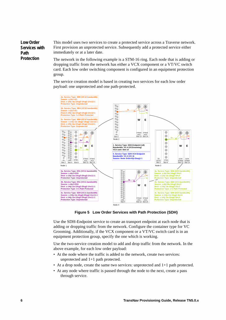
Low Order Services with Path Protection
This model uses two services to create a protected service across a Traverse network. First provision an unprotected service. Subsequently add a protected service either immediately or at a later date.
The network in the following example is a STM-16 ring. Each node that is adding or dropping traffic from the network has either a VCX component or a VT/VC switch card. Each low order switching component is configured in an equipment protection group.
The service creation model is based in creating two services for each low order payload: one unprotected and one path-protected.
.
Figure 5 Low Order Services with Path Protection (SDH)
Use the SDH-Endpoint service to create an transport endpoint at each node that is adding or dropping traffic from the network. Configure the container type for VC Grooming. Additionally, if the VCX component or a VT/VC switch card is in an equipment protection group, specify the one which is working.
Use the two-service creation model to add and drop traffic from the network. In the above example, for each low order payload:• At the node where the traffic is added to the network, create two services:
unprotected and 1+1 path protected. • At a drop node, create the same two services: unprotected and 1+1 path protected.• At any node where traffic is passed through the node to the next, create a pass
through service.
1. Service Type: SDH-Endpoint (x8)Bandwidth: VC-4 (VCGrooming)VCX card: Slot 14
Node 3
Slot 6
E
GCMSTM16Slot 14
W
GCMSTM16Slot 13
STM1
Node 1
Slot 2 Slot 4
2a
3a
4a
Slot 6E1
E
STM16VCX
Slot 14
W
STM16VCX
Slot 13
2b
3b
4b
DS1 STM1
1
5GVC/VT
5. Service Type: SDH-VC4 EndpointBandwidth: VC-4 (VC-3)Source: Node 3/slot-6/p-2/aug1-1
Slot 2
4a4b
1
2c
3c
E
STM16VCX
Slot 14
W
STM16VCX
Slot 13Slot 2E1
1
2a2b 3c
4c
E
STM16VCX
Slot 14
W
STM16VCX
Slot 13Slot 4DS1
1
3a3b
4c
2c
1
1
1
1
5
4c. Service Type: SDH (VC3 bandwidth)Source: s-13/p-1/a-1/tug3-3/vc3Dest: s-14/p-1/a-1/tug3-3/vc3Protection Type: Unprotected
2a. Service Type: SDH (VC12 bandwidth)Source: s-2/p-4 E1Dest: s-13/p-1/a-1/tug3-1/tug2-1/vc12-1Protection Type: Unprotected
2b. Service Type: SDH (VC12 bandwidth)Source: s-2/p-4 E1Dest:/s-14/p-1/a-1/tug3-1/tug2-1/vc12-1Protection Type: 1+1 Path Protected
2c. Service Type: SDH (VC12 bandwidth)Source: s-13/p-1/a-1/tug3-1/tug2-1/vc12-1Dest: s-14/p-1/a-1/tug3-1/tug2-1/vc12-1Protection Type: Unprotected
3a. Service Type: DS1 (VC11 bandwidth)Source: s-4/p-9 DS1Dest: s-13/p-1/a-1/tug3-2/tug2-1/vc11-1Protection Type: Unprotected
3b. Service Type: DS1 (VC11 bandwidth)Source: s-4/p-9 DS1Dest: s-14/p-1/a-1/tug3-2/tug2-1/vc11-1Protection Type: 1+1 Path Protected
3c. Service Type: SDH (VC11 bandwidth)Source: s-13/p-1/a-1/tug3-2/tug2-1/vc11-1Dest: s-14/p-1/a-1/tug3-2/tug2-1/vc11-1Protection Type: Unprotected
4a. Service Type: SDH (VC3 bandwidth)Source: s-6/p-6/a-1/tug3-3/vc3Dest: s-13/p-1/a-1/tug3-3/vc3Protection Type: Unprotected
4b. Service Type: SDH (VC3 bandwidth)Source: s-6/p-6/a-1/tug3-3/vc3Dest: s-14/p-1/a-1/tug3-3/vc3Protection Type: 1+1 Path Protected
Node 2
Node 4
6 TransNav Provisioning Guide, Release TN5.0.x
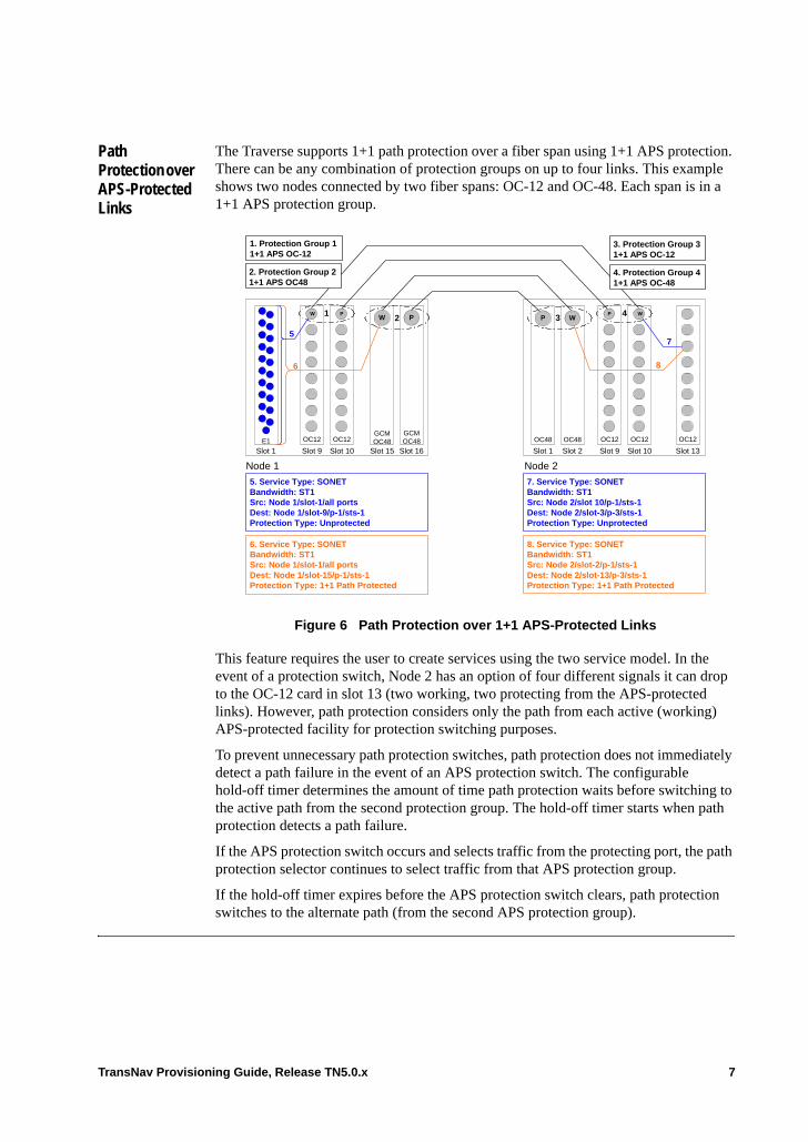
Path Protection over APS-Protected Links
The Traverse supports 1+1 path protection over a fiber span using 1+1 APS protection. There can be any combination of protection groups on up to four links. This example shows two nodes connected by two fiber spans: OC-12 and OC-48. Each span is in a 1+1 APS protection group.
Figure 6 Path Protection over 1+1 APS-Protected Links
This feature requires the user to create services using the two service model. In the event of a protection switch, Node 2 has an option of four different signals it can drop to the OC-12 card in slot 13 (two working, two protecting from the APS-protected links). However, path protection considers only the path from each active (working) APS-protected facility for protection switching purposes.
To prevent unnecessary path protection switches, path protection does not immediately detect a path failure in the event of an APS protection switch. The configurable hold-off timer determines the amount of time path protection waits before switching to the active path from the second protection group. The hold-off timer starts when path protection detects a path failure.
If the APS protection switch occurs and selects traffic from the protecting port, the path protection selector continues to select traffic from that APS protection group.
If the hold-off timer expires before the APS protection switch clears, path protection switches to the alternate path (from the second APS protection group).
Node 1
Slot 1
GCMOC48
Slot 16
GCMOC48
Slot 15
5. Service Type: SONETBandwidth: ST1Src: Node 1/slot-1/all portsDest: Node 1/slot-9/p-1/sts-1Protection Type: Unprotected
Node 2
OC48
Slot 10
OC48
Slot 9
7. Service Type: SONETBandwidth: ST1Src: Node 2/slot 10/p-1/sts-1Dest: Node 2/slot-3/p-3/sts-1Protection Type: Unprotected
3
E1
4
6. Service Type: SONETBandwidth: ST1Src: Node 1/slot-1/all portsDest: Node 1/slot-15/p-1/sts-1Protection Type: 1+1 Path Protected
8. Service Type: SONETBandwidth: ST1Src: Node 2/slot-2/p-1/sts-1Dest: Node 2/slot-13/p-3/sts-1Protection Type: 1+1 Path Protected
OC12 OC12 OC12 OC12 OC12
Slot 1Slot 10Slot 9 Slot 2
W PW P P
P
5
6
WW
7
8
Slot 13
2. Protection Group 21+1 APS OC48
3. Protection Group 31+1 APS OC-12
4. Protection Group 41+1 APS OC-48
12 3 4
1. Protection Group 11+1 APS OC-12
TransNav Provisioning Guide, Release TN5.0.x 7
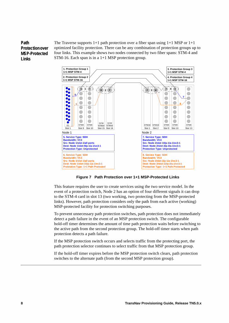
Path Protection over MSP-Protected Links
The Traverse supports 1+1 path protection over a fiber span using 1+1 MSP or 1+1 optimized facility protection. There can be any combination of protection groups up to four links. This example shows two nodes connected by two fiber spans: STM-4 and STM-16. Each span is in a 1+1 MSP protection group.
Figure 7 Path Protection over 1+1 MSP-Protected Links
This feature requires the user to create services using the two service model. In the event of a protection switch, Node 2 has an option of four different signals it can drop to the STM-4 card in slot 13 (two working, two protecting from the MSP-protected links). However, path protection considers only the path from each active (working) MSP-protected facility for protection switching purposes.
To prevent unnecessary path protection switches, path protection does not immediately detect a path failure in the event of an MSP protection switch. The configurable hold-off timer determines the amount of time path protection waits before switching to the active path from the second protection group. The hold-off timer starts when path protection detects a path failure.
If the MSP protection switch occurs and selects traffic from the protecting port, the path protection selector continues to select traffic from that MSP protection group.
If the hold-off timer expires before the MSP protection switch clears, path protection switches to the alternate path (from the second MSP protection group).
Node 1
Slot 1
GCMSTM16
Slot 16
GCMSTM16Slot 15
5. Service Type: SDHBandwidth: VC3Src: Node 1/slot-1/all portsDest: Node 1/slot-9/p-1/a-1/vc3-1Protection Type: Unprotected
Node 2
STM16
Slot 10
STM16
Slot 9
7. Service Type: SDHBandwidth: VC3Src: Node 2/slot 10/p-1/a-1/vc3-1Dest: Node 2/slot-3/p-3/a-1/vc3-1Protection Type: Unprotected
3
E1
4
6. Service Type: SDHBandwidth: VC3Src: Node 1/slot-1/all portsDest: Node 1/slot-15/p-1/a-1/vc3-1Protection Type: 1+1 Path Protected
8. Service Type: SDHBandwidth: VC3Src: Node 2/slot-2/p-1/a-1/vc3-1Dest: Node 2/slot-13/p-3/a-1/vc3-1Protection Type: 1+1 Path Protected
STM4 STM4 STM4 STM4 STM4
Slot 1Slot 10Slot 9 Slot 2
W PW P P
P
5
6
WW
7
8
Slot 13
1. Protection Group 11+1 MSP STM-4
2. Protection Group 21+1 MSP STM-16
3. Protection Group 31+1 MSP STM-4
4. Protection Group 41+1 MSP STM-16
12 3 4
8 TransNav Provisioning Guide, Release TN5.0.x
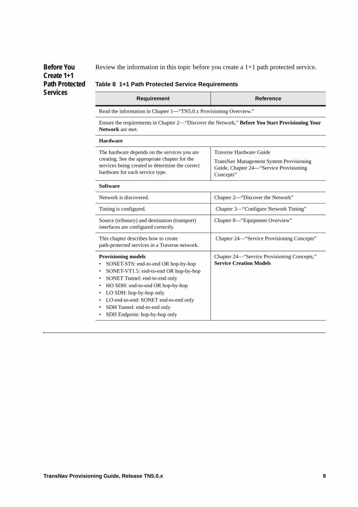
Before You Create 1+1 Path Protected Services
Review the information in this topic before you create a 1+1 path protected service.
Table 8 1+1 Path Protected Service Requirements
Requirement Reference
Read the information in Chapter 1—“TN5.0.x Provisioning Overview.”
Ensure the requirements in Chapter 2—“Discover the Network,” Before You Start Provisioning Your Network are met.
Hardware
The hardware depends on the services you are creating. See the appropriate chapter for the services being created to determine the correct hardware for each service type.
Traverse Hardware Guide
TransNav Management System Provisioning Guide, Chapter 24—“Service Provisioning Concepts”
Software
Network is discovered. Chapter 2—“Discover the Network”
Timing is configured. Chapter 3—“Configure Network Timing”
Source (tributary) and destination (transport) interfaces are configured correctly.
Chapter 8—“Equipment Overview”
This chapter describes how to create path-protected services in a Traverse network.
Chapter 24—“Service Provisioning Concepts”
Provisioning models • SONET-STS: end-to-end OR hop-by-hop• SONET-VT1.5: end-to-end OR hop-by-hop• SONET Tunnel: end-to-end only• HO SDH: end-to-end OR hop-by-hop• LO SDH: hop-by-hop only• LO end-to-end: SONET end-to-end only• SDH Tunnel: end-to-end only• SDH Endpoint: hop-by-hop only
Chapter 24—“Service Provisioning Concepts,” Service Creation Models
TransNav Provisioning Guide, Release TN5.0.x 9
Guidelines to Provision 1+1 Path Protected Services
The guidelines to provision a 1+1 path protected service are:• Use the 1+1 path protection group model to protect services created at the following
path levels: – High order AU-4– High order VC-3– Low order VC-3– STS
• Use the two services model to protect services of any bandwidth. • The network interfaces at the source and drop nodes cannot be part of an MS-SP ring
or a BLSR protection group. However, the interfaces can be part of an SNCP/UPSR protection group, a 1+1 APS protection group, a 1+1 MSP protection group, or unprotected.
• Provision the unprotected services first.• Provision the path-protected service or the protection group second.• At the intermediate nodes, the path numbers can be different.• If any part of the network has another type of protection, you must make the
cross-connection to the working facility.• Activate the services in any order, however, the service you activate first carries the
active traffic.• If end-to-end services are created for the unprotected services, Force10 recommends
using end-to-end services for the protecting services. That is, Force10 recommends not to use a hop-by-hop service to protect end-to-end services or vice versa.
• To perform a manual switch on an end-to-end service protected by a hop-by-hop service, perform the manual switch on the protecting hop-by-hop service.
Procedures Required to Create a 1+1 Path Protected Service
Use the procedures in the following chapters to help you provision 1+1 path protected services on a Traverse system:
1. Chapter 27—“Configuring SONET Services”
2. Chapter 29—“Configuring SDH Services”
3. Chapter 21—“Creating a 1+1 Path Protection Group”
4. Chapter 26—“Common Procedures for Services,” Activate or Deactivate a Service
10 TransNav Provisioning Guide, Release TN5.0.x
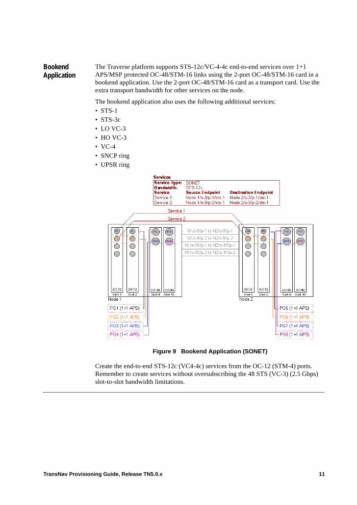
Bookend Application
The Traverse platform supports STS-12c/VC-4-4c end-to-end services over 1+1 APS/MSP protected OC-48/STM-16 links using the 2-port OC-48/STM-16 card in a bookend application. Use the 2-port OC-48/STM-16 card as a transport card. Use the extra transport bandwidth for other services on the node.
The bookend application also uses the following additional services:• STS-1• STS-3c• LO VC-3• HO VC-3• VC-4• SNCP ring• UPSR ring
Figure 9 Bookend Application (SONET)
Create the end-to-end STS-12c (VC4-4c) services from the OC-12 (STM-4) ports. Remember to create services without oversubscribing the 48 STS (VC-3) (2.5 Gbps) slot-to-slot bandwidth limitations.
TransNav Provisioning Guide, Release TN5.0.x 11
Guidelines to Create a Bookend Application
The guidelines to provision a bookend application are:• Configure the 1+1 APS/MSP protection groups on the 2-port OC-48 (STM-16) cards
using port 2 of one card as the working port and port 1 of the other card as the protecting port.
• When engineering other services using the rest of the transport bandwidth from the 2-port OC-48 (STM-16) card, plan for the 48 STS (VC-3) (2.5 Gbps) slot-to-slot bandwidth limitation.
Procedures Required to Create a Bookend Application
Use the following procedures to help you create a bookend application on 1+1 path-protected services on a Traverse system:
1. Create a 1+1 Path Protection Group
2. Chapter 24—“Service Provisioning Concepts”
3. Chapter 26—“Common Procedures for Services”
4. Chapter 27—“Configuring SONET Services”
5. Chapter 29—“Configuring SDH Services”
12 TransNav Provisioning Guide, Release TN5.0.x
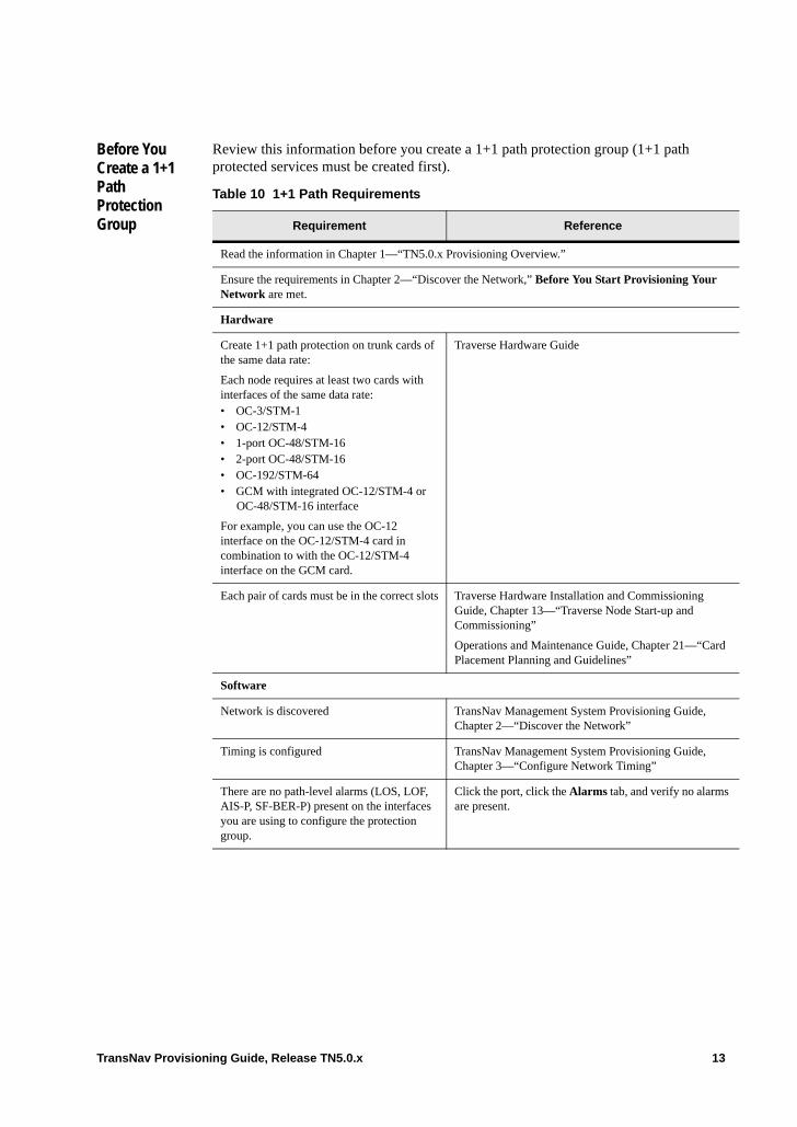
Before You Create a 1+1 Path Protection Group
Review this information before you create a 1+1 path protection group (1+1 path protected services must be created first).
Table 10 1+1 Path Requirements
Requirement Reference
Read the information in Chapter 1—“TN5.0.x Provisioning Overview.”
Ensure the requirements in Chapter 2—“Discover the Network,” Before You Start Provisioning Your Network are met.
Hardware
Create 1+1 path protection on trunk cards of the same data rate:
Each node requires at least two cards with interfaces of the same data rate:• OC-3/STM-1 • OC-12/STM-4• 1-port OC-48/STM-16• 2-port OC-48/STM-16• OC-192/STM-64• GCM with integrated OC-12/STM-4 or
OC-48/STM-16 interface
For example, you can use the OC-12 interface on the OC-12/STM-4 card in combination to with the OC-12/STM-4 interface on the GCM card.
Traverse Hardware Guide
Each pair of cards must be in the correct slots Traverse Hardware Installation and Commissioning Guide, Chapter 13—“Traverse Node Start-up and Commissioning”
Operations and Maintenance Guide, Chapter 21—“Card Placement Planning and Guidelines”
Software
Network is discovered TransNav Management System Provisioning Guide, Chapter 2—“Discover the Network”
Timing is configured TransNav Management System Provisioning Guide, Chapter 3—“Configure Network Timing”
There are no path-level alarms (LOS, LOF, AIS-P, SF-BER-P) present on the interfaces you are using to configure the protection group.
Click the port, click the Alarms tab, and verify no alarms are present.
TransNav Provisioning Guide, Release TN5.0.x 13
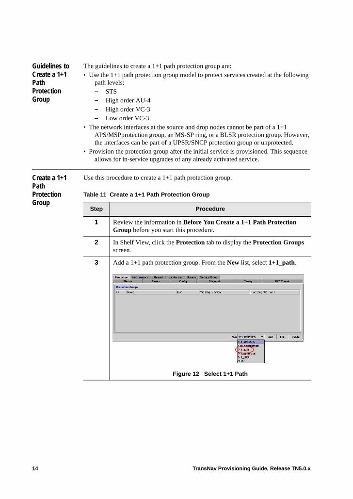
Guidelines to Create a 1+1 Path Protection Group
The guidelines to create a 1+1 path protection group are:• Use the 1+1 path protection group model to protect services created at the following
path levels: – STS– High order AU-4– High order VC-3– Low order VC-3
• The network interfaces at the source and drop nodes cannot be part of a 1+1 APS/MSPprotection group, an MS-SP ring, or a BLSR protection group. However, the interfaces can be part of a UPSR/SNCP protection group or unprotected.
• Provision the protection group after the initial service is provisioned. This sequence allows for in-service upgrades of any already activated service.
Create a 1+1 Path Protection Group
Use this procedure to create a 1+1 path protection group.
Table 11 Create a 1+1 Path Protection Group
Step Procedure
1 Review the information in Before You Create a 1+1 Path Protection Group before you start this procedure.
2 In Shelf View, click the Protection tab to display the Protection Groups screen.
3 Add a 1+1 path protection group. From the New list, select 1+1_path.
Figure 12 Select 1+1 Path
14 TransNav Provisioning Guide, Release TN5.0.x
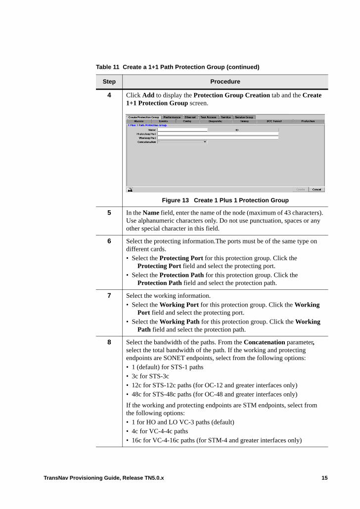
4 Click Add to display the Protection Group Creation tab and the Create 1+1 Protection Group screen.
Figure 13 Create 1 Plus 1 Protection Group
5 In the Name field, enter the name of the node (maximum of 43 characters). Use alphanumeric characters only. Do not use punctuation, spaces or any other special character in this field.
6 Select the protecting information.The ports must be of the same type on different cards.• Select the Protecting Port for this protection group. Click the
Protecting Port field and select the protecting port.• Select the Protection Path for this protection group. Click the
Protection Path field and select the protection path.
7 Select the working information.• Select the Working Port for this protection group. Click the Working
Port field and select the protecting port.• Select the Working Path for this protection group. Click the Working
Path field and select the protection path.
8 Select the bandwidth of the paths. From the Concatenation parameter, select the total bandwidth of the path. If the working and protecting endpoints are SONET endpoints, select from the following options: • 1 (default) for STS-1 paths• 3c for STS-3c• 12c for STS-12c paths (for OC-12 and greater interfaces only)• 48c for STS-48c paths (for OC-48 and greater interfaces only)
If the working and protecting endpoints are STM endpoints, select from the following options: • 1 for HO and LO VC-3 paths (default)• 4c for VC-4-4c paths• 16c for VC-4-16c paths (for STM-4 and greater interfaces only)
Table 11 Create a 1+1 Path Protection Group (continued)
Step Procedure
TransNav Provisioning Guide, Release TN5.0.x 15
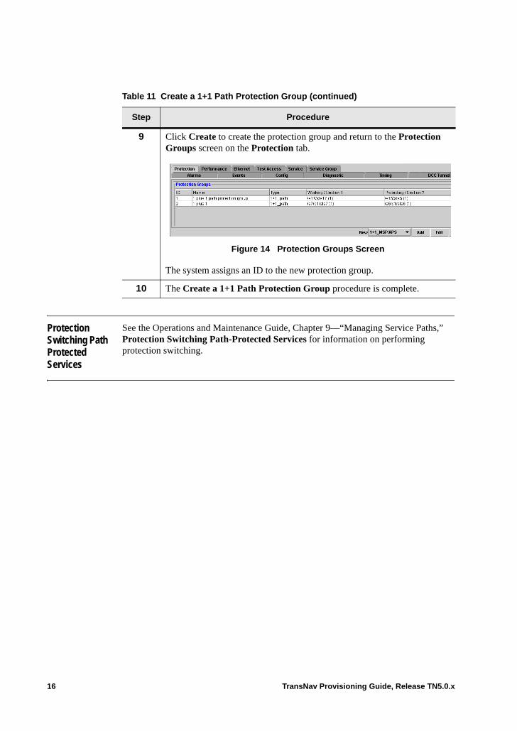
Protection Switching Path Protected Services
See the Operations and Maintenance Guide, Chapter 9—“Managing Service Paths,” Protection Switching Path-Protected Services for information on performing protection switching.
9 Click Create to create the protection group and return to the Protection Groups screen on the Protection tab.
Figure 14 Protection Groups Screen
The system assigns an ID to the new protection group.
10 The Create a 1+1 Path Protection Group procedure is complete.
Table 11 Create a 1+1 Path Protection Group (continued)
Step Procedure
16 TransNav Provisioning Guide, Release TN5.0.x
Chapter 32 Bridging and Rolling Services
Introduction This chapter includes the following topics:• Bridging and Rolling Services• Bridge and Roll in a UPSR/SNCP Protection Group• Bridge and Roll in a Single 1+1 APS/MPS Protection Group• Guidelines to Create Bridge and Roll Services• Procedures Required to Bridge and Roll Services• Bridge and Roll Services• Create a Persistent Bridge Service
If your system includes 2-port OC-48 cards, see Chapter 30—“Creating 2-Port OC-48/STM-16 Services” for additional information.
Bridging and Rolling Services
The Traverse system supports a bridge and roll feature that allows an operator to transfer services from one facility to another without dropping traffic. In-service transition allows one or more cross-connects to be moved from one facility to another without interrupting traffic. This operation is non-service affecting (less than 2 ms). This operation takes less time than a protection switch event.
TransNav Provisioning Guide, Release TN5.0.x 1
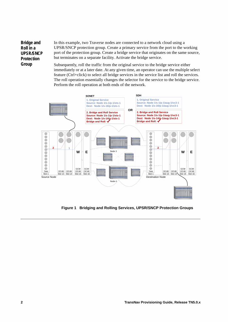
Bridge and Roll in a UPSR/SNCP Protection Group
In this example, two Traverse nodes are connected to a network cloud using a UPSR/SNCP protection group. Create a primary service from the port to the working port of the protection group. Create a bridge service that originates on the same source, but terminates on a separate facility. Activate the bridge service.
Subsequently, roll the traffic from the original service to the bridge service either immediately or at a later date. At any given time, an operator can use the multiple select feature (Ctrl+click) to select all bridge services in the service list and roll the services. The roll operation essentially changes the selector for the service to the bridge service. Perform the roll operation at both ends of the network.
Figure 1 Bridging and Rolling Services, UPSR/SNCP Protection Groups
SONET
Destination NodeSource NodeSlot 1TMX
Slot 16
W
GCMOC48Slot 15
OC48 OC48Slot 14Slot 13
1. Original ServiceSource: Node 1/s-1/p-1/sts-1Dest: Node 1/s-16/p-1/sts-1
2. Bridge and Roll ServiceSource: Node 1/s-1/p-1/sts-1Dest: Node 1/s-14/p-1/sts-1Bridge and Roll:
2 1
1. Original ServiceSource: Node 1/s-1/p-1/aug-1/vc3-1Dest: Node 1/s-16/p-1/aug-1/vc3-1
2. Bridge and Roll ServiceSource: Node 1/s-1/p-1/aug-1/vc3-1Dest: Node 1/s-14/p-1/aug-1/vc3-1Bridge and Roll:
OR
Node 4
Node 3
Slot 1
E
GCMOC48 TMX
E
GCMOC48Slot 16
W
GCMOC48Slot 15
OC48Slot 13
2 1
OC48Slot 14
SDH
2 TransNav Provisioning Guide, Release TN5.0.x
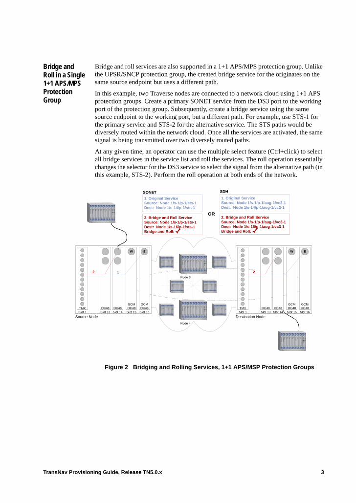
Bridge and Roll in a Single 1+1 APS/MPS Protection Group
Bridge and roll services are also supported in a 1+1 APS/MPS protection group. Unlike the UPSR/SNCP protection group, the created bridge service for the originates on the same source endpoint but uses a different path.
In this example, two Traverse nodes are connected to a network cloud using 1+1 APS protection groups. Create a primary SONET service from the DS3 port to the working port of the protection group. Subsequently, create a bridge service using the same source endpoint to the working port, but a different path. For example, use STS-1 for the primary service and STS-2 for the alternative service. The STS paths would be diversely routed within the network cloud. Once all the services are activated, the same signal is being transmitted over two diversely routed paths.
At any given time, an operator can use the multiple select feature (Ctrl+click) to select all bridge services in the service list and roll the services. The roll operation essentially changes the selector for the DS3 service to select the signal from the alternative path (in this example, STS-2). Perform the roll operation at both ends of the network.
Figure 2 Bridging and Rolling Services, 1+1 APS/MSP Protection Groups
SONET
Destination NodeSource NodeSlot 1TMX
Slot 16
GCMOC48
W
Slot 15OC48 OC48
Slot 14Slot 13
1. Original ServiceSource: Node 1/s-1/p-1/sts-1Dest: Node 1/s-14/p-1/sts-1
2. Bridge and Roll ServiceSource: Node 1/s-1/p-1/sts-1Dest: Node 1/s-16/p-1/sts-1Bridge and Roll:
2 1
1. Original ServiceSource: Node 1/s-1/p-1/aug-1/vc3-1Dest: Node 1/s-14/p-1/aug-1/vc3-1
2. Bridge and Roll ServiceSource: Node 1/s-1/p-1/aug-1/vc3-1Dest: Node 1/s-16/p-1/aug-1/vc3-1Bridge and Roll:
OR
Node 4
Node 3
Slot 1
GCMOC48 TMX
GCMOC48Slot 16
GCMOC48
W
Slot 15OC48Slot 13
2 1
OC48Slot 14
E
SDH
E
TransNav Provisioning Guide, Release TN5.0.x 3

Guidelines to Create Bridge and Roll Services
The Traverse system supports bridge and roll services for the following bandwidths of services:• VT1.5• STS-1• STS-3c• STS-12c• STS-48c• HO VC-3• VC-4• VC-4-4c• VC-4-16c
The destination of the bridge service can be on a separate transport card. For example, the working card of a second protection group. See Bridge and Roll Services for the related procedure.
The destination of the bridge service can be on a separate path of the same working transport card of the original service. In this case, the separate path would be an alternative route through the network. See Create a Persistent Bridge Service for the related procedure.
You can roll and unroll traffic as often as required without using the commit function. The commit function transforms the bridge service to a regular service by removing the Bridge and Roll attribute.
Procedures Required to Bridge and Roll Services
Use the following procedures to help you bridge and roll services on a Traverse system.
1. Chapter 27—“Configuring SONET Services,” Create a SONET Service
2. Chapter 29—“Configuring SDH Services,” Create an SDH Service
3. Chapter 26—“Common Procedures for Services,” Activate or Deactivate a Service
4 TransNav Provisioning Guide, Release TN5.0.x
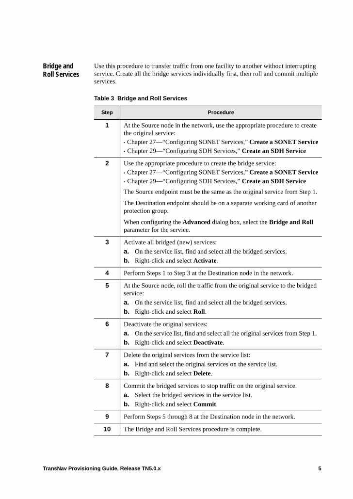
Bridge and Roll Services
Use this procedure to transfer traffic from one facility to another without interrupting service. Create all the bridge services individually first, then roll and commit multiple services.
Table 3 Bridge and Roll Services
Step Procedure
1 At the Source node in the network, use the appropriate procedure to create the original service: • Chapter 27—“Configuring SONET Services,” Create a SONET Service• Chapter 29—“Configuring SDH Services,” Create an SDH Service
2 Use the appropriate procedure to create the bridge service: • Chapter 27—“Configuring SONET Services,” Create a SONET Service• Chapter 29—“Configuring SDH Services,” Create an SDH Service
The Source endpoint must be the same as the original service from Step 1.
The Destination endpoint should be on a separate working card of another protection group.
When configuring the Advanced dialog box, select the Bridge and Roll parameter for the service.
3 Activate all bridged (new) services:
a. On the service list, find and select all the bridged services.
b. Right-click and select Activate.
4 Perform Steps 1 to Step 3 at the Destination node in the network.
5 At the Source node, roll the traffic from the original service to the bridged service:
a. On the service list, find and select all the bridged services.
b. Right-click and select Roll.
6 Deactivate the original services:
a. On the service list, find and select all the original services from Step 1.
b. Right-click and select Deactivate.
7 Delete the original services from the service list:
a. Find and select the original services on the service list.
b. Right-click and select Delete.
8 Commit the bridged services to stop traffic on the original service.
a. Select the bridged services in the service list.
b. Right-click and select Commit.
9 Perform Steps 5 through 8 at the Destination node in the network.
10 The Bridge and Roll Services procedure is complete.
TransNav Provisioning Guide, Release TN5.0.x 5

Create a Persistent Bridge Service
Use this procedure to transfer traffic from one path to another diversely routed path without interrupting service. Create all the bridge services individually first. Subsequently (either immediately or at a later time) roll and unroll multiple services to transfer traffic.
Table 4 Create a Persistent Bridge Service
Step Procedure
1 At the Source node in the network, use the appropriate procedure to create the original service: • Chapter 27—“Configuring SONET Services,” Create a SONET Service• Chapter 29—“Configuring SDH Services,” Create an SDH Service
2 Use the appropriate procedure to create the bridge service: • Chapter 27—“Configuring SONET Services,” Create a SONET Service• Chapter 29—“Configuring SDH Services,” Create an SDH Service
The Source endpoint must be the same as the original service from Step 1.
The Destination endpoint should be on a separate path of the same working card of the same protection group.
When configuring the Advanced dialog box, select the Bridge and Roll parameter for the service.
3 Activate all bridged (new) services.
a. On the service list, find and select all the bridged services.
b. Right-click and select Activate.
4 Perform Steps 1 to Step 3 at the Destination node in the network.
5 When required, roll the traffic from the original service to the bridge service. Perform the roll operation at both nodes (C nodes).
a. On the service list, find and select all the bridge services. Use the multiple select option (Ctrl + click) to select multiple services.
b. Right-click and select Roll.
6 When required, unroll the traffic from the bridge service to the original service. Perform the unroll operation at both nodes (VL nodes).
a. On the service list, find and select all the bridged services. Use the multiple select option (Ctrl + click) to select multiple services.
b. Right-click and select Unroll.
7 The Create a Persistent Bridge Service procedure is complete.
6 TransNav Provisioning Guide, Release TN5.0.x

Chapter 33 Creating Drop-and-Continue Services
Introduction This chapter explains how to create a drop-and-continue service in a Traverse network. • Drop and Continue Services• Example of a Drop and Continue Service (SONET)• Ethernet Services and Drop and Continue Applications• Cards Required to Create Drop and Continue Service• Before You Create a Drop and Continue Service• Guidelines to Provision Drop and Continue Services• Procedures Required to Provision a Drop and Continue Service• Parameters Required to Provision Drop and Continue Services
If your system includes 2-port OC-48 cards, see Chapter 30—“Creating 2-Port OC-48/STM-16 Services” for additional information.
Drop and Continue Services
Drop-and-continue applications allow you to add traffic to a UPSR or SNCP ring, drop traffic at one location, and continue the signal to another destination around the ring. To provision a drop-and-continue service, you need to provision a combination of three types of services at different nodes in the network.
1. Add Service: This service adds the traffic to the ring. You provision this service at the node where the traffic enters the ring. The source of this service is a tributary port. The destination is either trunk port (East or West) of the ring. You create this add service as FULL or ANY protected; the system creates both the working and protection paths around the ring
2. Drop Service: This service drops traffic from the ring. You provision this service at any node for traffic traveling in either direction around the ring. The source of this service is the trunk port (East or West) that receives the added traffic from the ring. The destination is the port which drops the added traffic from the ring.
3. Continue Service: This service carries the traffic around the ring. After you have dropped traffic at one node, you continue the path around the network. You provision one unidirectional continue service at any node for traffic traveling in both directions around the ring. The source of this service is the trunk port (East or West) that receives the added traffic from the ring. The destination is the other trunk card on the node.
TransNav Provisioning Guide, Release TN5.0.x 1

Provision all required services on one node before you move to the next. That is, configure the services hop-by-hop through the network. Provision and activate the drop service before you provision the continue service.
2 TransNav Provisioning Guide, Release TN5.0.x
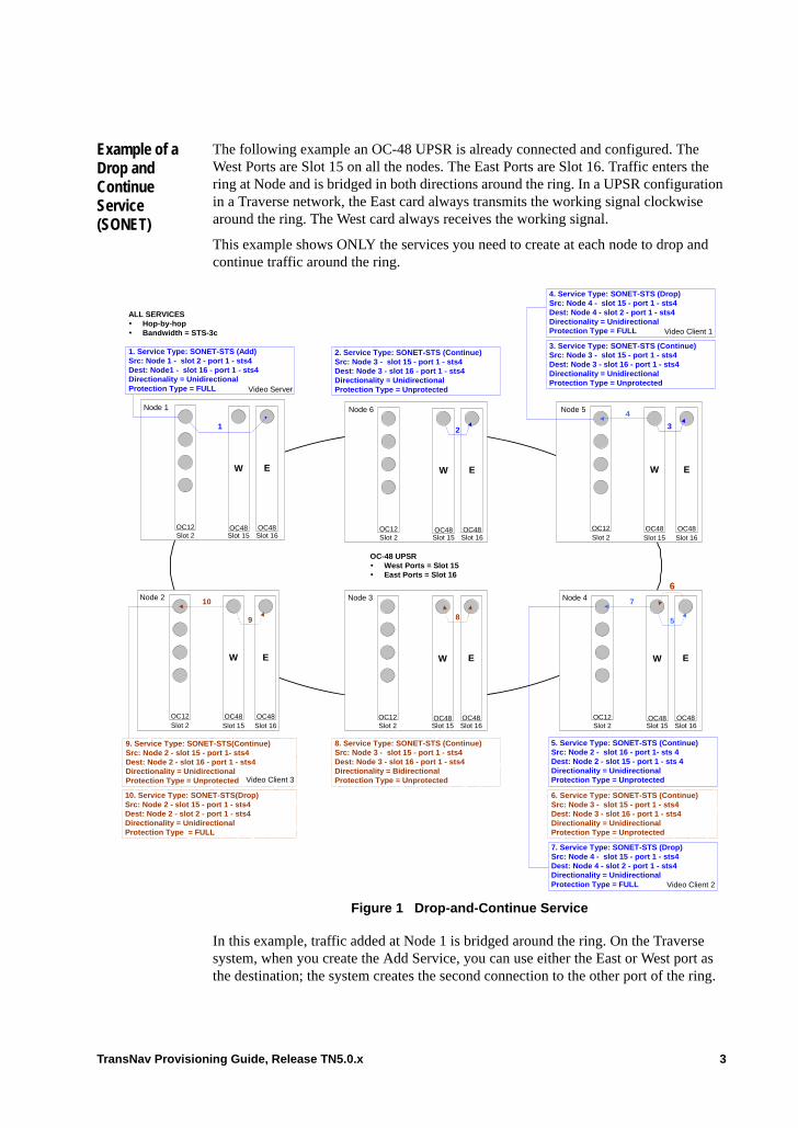
Example of a Drop and Continue Service (SONET)
The following example an OC-48 UPSR is already connected and configured. The West Ports are Slot 15 on all the nodes. The East Ports are Slot 16. Traffic enters the ring at Node and is bridged in both directions around the ring. In a UPSR configuration in a Traverse network, the East card always transmits the working signal clockwise around the ring. The West card always receives the working signal.
This example shows ONLY the services you need to create at each node to drop and continue traffic around the ring.
Figure 1 Drop-and-Continue Service
In this example, traffic added at Node 1 is bridged around the ring. On the Traverse system, when you create the Add Service, you can use either the East or West port as the destination; the system creates the second connection to the other port of the ring.
9. Service Type: SONET-STS(Continue)Src: Node 2 - slot 15 - port 1- sts4Dest: Node 2 - slot 16 - port 1 - sts4Directionality = UnidirectionalProtection Type = Unprotected
ALL SERVICES Hop-by-hop Bandwidth = STS-3c
1. Service Type: SONET-STS (Add)Src: Node 1 - slot 2 - port 1 - sts4Dest: Node1 - slot 16 - port 1 - sts4Directionality = UnidirectionalProtection Type = FULL
2. Service Type: SONET-STS (Continue)Src: Node 3 - slot 15 - port 1 - sts4Dest: Node 3 - slot 16 - port 1 - sts4Directionality = UnidirectionalProtection Type = UnprotectedVideo Server
6. Service Type: SONET-STS (Continue)Src: Node 3 - slot 15 - port 1 - sts4Dest: Node 3 - slot 16 - port 1 - sts4Directionality = UnidirectionalProtection Type = Unprotected
5. Service Type: SONET-STS (Continue)Src: Node 2 - slot 16 - port 1- sts 4Dest: Node 2 - slot 15 - port 1 - sts 4Directionality = UnidirectionalProtection Type = UnprotectedVideo Client 3
EW
Node 3
Slot 16OC12Slot 2 Slot 15
OC48OC48
8
EW
Node 4
Slot 16OC12Slot 2 Slot 15
OC48OC48
6
5
8. Service Type: SONET-STS (Continue)Src: Node 3 - slot 15 - port 1 - sts4Dest: Node 3 - slot 16 - port 1 - sts4Directionality = BidirectionalProtection Type = Unprotected
W E
Slot 16OC12Slot 2 Slot 15
OC48OC48
1
Node 1
EW
Node 6
Slot 16OC12Slot 2 Slot 15
OC48OC48
2
Node 2
W
OC48Slot 15Slot 2
E
OC48Slot 16
OC12
9
10
Node 5
W
OC48Slot 15Slot 2
E
OC48Slot 16
OC12
3. Service Type: SONET-STS (Continue)Src: Node 3 - slot 15 - port 1 - sts4Dest: Node 3 - slot 16 - port 1 - sts4Directionality = UnidirectionalProtection Type = Unprotected
OC-48 UPSR West Ports = Slot 15 East Ports = Slot 16
10. Service Type: SONET-STS(Drop)Src: Node 2 - slot 15 - port 1 - sts4Dest: Node 2 - slot 2 - port 1 - sts4Directionality = UnidirectionalProtection Type = FULL
7. Service Type: SONET-STS (Drop)Src: Node 4 - slot 15 - port 1 - sts4Dest: Node 4 - slot 2 - port 1 - sts4Directionality = UnidirectionalProtection Type = FULL
7
4. Service Type: SONET-STS (Drop)Src: Node 4 - slot 15 - port 1 - sts4Dest: Node 4 - slot 2 - port 1 - sts4Directionality = UnidirectionalProtection Type = FULL
4
Video Client 1
3
Video Client 2
TransNav Provisioning Guide, Release TN5.0.x 3

For any service that has Protection Type = UPSR, the system creates the second connection from the signal traveling in the opposite direction around the ring.
4 TransNav Provisioning Guide, Release TN5.0.x

Example of a Drop and Continue Service (SDH)
The following example an STM-16 SNCP ring is already connected and configured. The West Ports are Slot 15 on all the nodes. The East Ports are Slot 16. Traffic enters the ring at Node and is bridged in both directions around the ring. In an SNCP ring configuration in a Traverse network, the East card always transmits the working signal clockwise around the ring. The West card always receives the working signal.
This example shows ONLY the services you need to create at each node to drop and continue traffic around the ring.
Figure 2 Drop-and-Continue Service
In this example, traffic added at Node 1 is bridged around the ring. On the Traverse system, when you create the Add Service, you can use either the East or West port as the destination; the system creates the second connection to the other port of the ring. For any service that has Protection Type =UPSR/SNCP, the system creates the second connection from the signal traveling in the opposite direction around the ring.
EW
W E
9. Continue Service: SDH-VC4Src: Node 6/slot-15/port-1/aug1-1Dest: Node 6/slot-16/port-1/aug1-1Directionality = UnidirectionalProtection Type = Unprotected
ALL SERVICES Hop-by-hop Bandwidth = VC-4
1. Service Type: SDH-VC4 (Add)Src: Node 1/slot-2/port-1/aug1-1Dest: Node1/slot-16/port-1/aug1-1Directionality = UnidirectionalProtection Type = FULL
2. Service Type: SDH-VC4 (Continue)Src: Node 2/slot-15/port-1/aug1-1Dest: Node 2/slot-16/port-1/aug1-1Directionality = UnidirectionalProtection Type = UnprotectedVideo Server
EW
Node 5
Slot 16STM4Slot 2 Slot 15
8
EW
Node 4
Slot 16STM4Slot 2 Slot 15
8. Service Type: SDH-VC4 (Continue)Src: Node 5/slot-15/port-1/aug1-1Dest: Node 5/slot-16/port-1/aug1-1Directionality = BidirectionalProtection Type = Unprotected
Slot 16STM4
Slot 2 Slot 15
1
Node 1
EW
Node 2
Slot 16
STM4
Slot 2 Slot 15
GCMSTM16
Node 6
Slot 15Slot 2 Slot 16
STM4
9
10
Node 3
Slot 15Slot 2 Slot 16
STM4
3. Service Type: SDH-VC4 (Continue)Src: Node 3/slot-15/port-1/aug1-1Dest: Node 3/slot-16/port-1/aug1-1Directionality = UnidirectionalProtection Type = Unprotected
STM-16 SNCP West Ports = Slot 15 East Ports = Slot 16
7. Service Type: SDH-VC4 (Drop)Src: Node 4/slot-15/port-1/aug1-1Dest: Node 4/slot-1/port-1/aug1-1Directionality = UnidirectionalProtection Type = FULL
7
4
32
6
5
5. Service Type: SDH-VC4 (Continue)Src: Node 4/slot-15/port-1/aug1-1Dest: Node 4/slot-16/port-1/aug1-1Directionality = UnidirectionalProtection Type = Unprotected
Video Client 2
6. Service Type: SDH-VC4 (Continue)Src: Node 4/slot-16/port-1/aug1-1Dest: Node 4/slot-15/port-1/aug1-1Directionality = UnidirectionalProtection Type = Unprotected
4. Service Type: SDH-VC4 (Drop)Src: Node 3/slot-15/port-1/aug1-1Dest: Node 3/slot-2/port-1/aug1-1Directionality = UnidirectionalProtection Type = FULL Video Client 3
GCMSTM16
GCMSTM16
GCMSTM16
GCMSTM16
GCMSTM16
GCMSTM16
GCMSTM16
GCMSTM16
GCMSTM16
GCMSTM16
GCMSTM16
10. Service Type: SDH-VC4 (Drop)Src: Node 6/slot-15/port-1/aug1-1Dest: Node 6/slot-2/port-1/aug1-1Directionality = UnidirectionalProtection Type = FULL Video Client 1
TransNav Provisioning Guide, Release TN5.0.x 5

Ethernet Services and Drop and Continue Applications
To create Ethernet services in a drop-and-continue application (such as video broadcast), use the same example (Figure 1 Drop-and-Continue Service). However, the Add service would originate on an Ethernet card. The Drop service would terminate on an Ethernet card.
Cards Required to Create Drop and Continue Service
This table lists the Traverse cards required to create a drop-and-continue services.
Before You Create a Drop and Continue Service
Review the information in this topic before you create a drop-and-continue service.
Table 3 Cards Required for Drop-and-Continue Services
Service Type Source Card Destination Card
SDH STM-NAny Ethernet card
STM-NAny Ethernet card
SONET OC-NAny Ethernet card
OC-NAny Ethernet card
Table 4 Drop-and-Continue Service Requirements
Requirement Reference
Read the information in Chapter 1—“TN5.0.x Provisioning Overview”
Ensure the requirements in Chapter 2—“Discover the Network,” Before You Start Provisioning Your Network are met.
Hardware
See Cards Required to Create Drop and Continue Service.
The hardware depends on the services you are creating. See the appropriate chapter in the Traverse Hardware Guide to determine the correct hardware for each service type.
Traverse Hardware Guide
TransNav Management System Provisioning Guide, Chapter 24—“Service Provisioning Concepts”
Software
Network is discovered. Chapter 2—“Discover the Network”
Timing is configured. Chapter 3—“Configure Network Timing”
Source (tributary) and destination (transport) interfaces are configured correctly.
Chapter 8—“Equipment Overview”
These procedures describe how to create a specific service and change relevant parameters only.
• Chapter 27—“Configuring SONET Services”• Chapter 29—“Configuring SDH Services”
6 TransNav Provisioning Guide, Release TN5.0.x
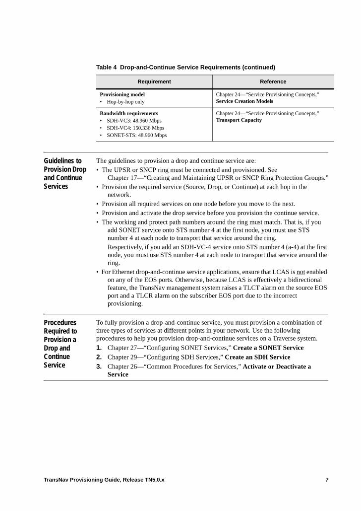
Guidelines to Provision Drop and Continue Services
The guidelines to provision a drop and continue service are:• The UPSR or SNCP ring must be connected and provisioned. See
Chapter 17—“Creating and Maintaining UPSR or SNCP Ring Protection Groups.”• Provision the required service (Source, Drop, or Continue) at each hop in the
network.• Provision all required services on one node before you move to the next.• Provision and activate the drop service before you provision the continue service.• The working and protect path numbers around the ring must match. That is, if you
add SONET service onto STS number 4 at the first node, you must use STS number 4 at each node to transport that service around the ring. Respectively, if you add an SDH-VC-4 service onto STS number 4 (a-4) at the first node, you must use STS number 4 at each node to transport that service around the ring.
• For Ethernet drop-and-continue service applications, ensure that LCAS is not enabled on any of the EOS ports. Otherwise, because LCAS is effectively a bidirectional feature, the TransNav management system raises a TLCT alarm on the source EOS port and a TLCR alarm on the subscriber EOS port due to the incorrect provisioning.
Procedures Required to Provision a Drop and Continue Service
To fully provision a drop-and-continue service, you must provision a combination of three types of services at different points in your network. Use the following procedures to help you provision drop-and-continue services on a Traverse system.
1. Chapter 27—“Configuring SONET Services,” Create a SONET Service
2. Chapter 29—“Configuring SDH Services,” Create an SDH Service
3. Chapter 26—“Common Procedures for Services,” Activate or Deactivate a Service
Provisioning model • Hop-by-hop only
Chapter 24—“Service Provisioning Concepts,” Service Creation Models
Bandwidth requirements • SDH-VC3: 48.960 Mbps• SDH-VC4: 150.336 Mbps• SONET-STS: 48.960 Mbps
Chapter 24—“Service Provisioning Concepts,” Transport Capacity
Table 4 Drop-and-Continue Service Requirements (continued)
Requirement Reference
TransNav Provisioning Guide, Release TN5.0.x 7
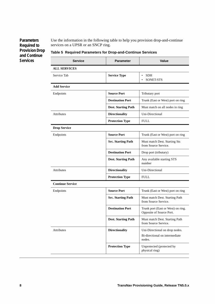
Parameters Required to Provision Drop and Continue Services
Use the information in the following table to help you provision drop-and-continue services on a UPSR or an SNCP ring.
Table 5 Required Parameters for Drop-and-Continue Services
Service Parameter Value
ALL SERVICES
Service Tab Service Type • SDH• SONET-STS
Add Service
Endpoints Source Port Tributary port
Destination Port Trunk (East or West) port on ring
Dest. Starting Path Must match on all nodes in ring
Attributes Directionality Uni-Directional
Protection Type FULL
Drop Service
Endpoints Source Port Trunk (East or West) port on ring
Src. Starting Path Must match Dest. Starting Sts from Source Service.
Destination Port Drop port (tributary)
Dest. Starting Path Any available starting STS number
Attributes Directionality Uni-Directional
Protection Type FULL
Continue Service
Endpoints Source Port Trunk (East or West) port on ring
Src. Starting Path Must match Dest. Starting Path from Source Service.
Destination Port Trunk port (East or West) on ring. Opposite of Source Port.
Dest. Starting Path Must match Dest. Starting Path from Source Service.
Attributes Directionality Uni-Directional on drop nodes.
Bi-directional on intermediate nodes.
Protection Type Unprotected (protected by physical ring)
8 TransNav Provisioning Guide, Release TN5.0.x

Chapter 34 Creating Services over Interconnected UPSR or SNCP Rings
Introduction This chapter explains how to create path-protected bidirectional services in a 2-node interconnected ring configuration. • Services over Interconnected UPSR or SNCP Rings• Example of a SONET Bi-directional Protected Path• Example of Bi-directional Protected E1 and VT Services• Cards Required at Interconnecting Nodes• Before You Create Services over Interconnected Rings• Guidelines to Provision Services over Interconnected Rings• Procedures Required to Provision Services over Interconnected Rings
If your system includes 2-port OC-48 or STM-16 cards, see Chapter 30—“Creating 2-Port OC-48/STM-16 Services” for additional information.
Services over Interconnected UPSR or SNCP Rings
Interconnected ring configurations use the same two or more nodes in separate ring topologies.
To provision services in an interconnected ring configuration, create a combination of the following services at different nodes in the network:• Add Service: This service can be any one of the supported service types. Create this
service at each node that adds traffic to both of the interconnected rings.• Pass Through Service: This service is a SONET or SDH service that passes the
traffic though the node. Create this type of service at all intermediate nodes in the interconnected ring configuration that do not add or drop traffic.
• Drop Service: This service drops traffic from one ring to the other. Create this service at each interconnecting node (a node that is a member of both ring configurations).
• Continue Service: This service carries the traffic to the next interconnecting node. After you have dropped traffic at the first interconnecting node, continue the signal around to the next interconnecting node to create an alternative path for the traffic. Create this service at each interconnecting node.
TransNav Provisioning Guide, Release TN5.0.x 1
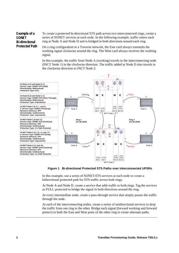
Example of a SONET Bi-directional Protected Path
To create a protected bi-directional STS path across two interconnected rings, create a series of SONET services at each node. In the following example, traffic enters each ring at Node A and Node D and is bridged in both directions around each ring.
On a ring configuration in a Traverse network, the East card always transmits the working signal clockwise around the ring. The West card always receives the working signal.
In this example, the traffic from Node A (working) travels to the interconnecting node (INCT Node 1) in the clockwise direction. The traffic added at Node D also travels in the clockwise direction to INCT Node 2.
Figure 1 Bi-directional Protected STS Paths over Interconnected UPSRs
In this example, use a series of SONET-STS services at each node to create a bidirectional protected path for STS traffic across both rings.
At Node A and Node D, create a service that adds traffic to both rings. Tag the services as FULL protected to bridge the signal in both directions around the ring.
At every intermediate node, create a pass-through service that simply passes the traffic through the node.
At each of the interconnecting nodes, create a series of unidirectional services to drop the traffic from one ring to the other. Bridge each signal (forward working and forward protect) to both the East and West ports of the other ring to create alternate paths.
W
Slot 2Slot 1
E
OC48OC48
Slot 16Slot 15
W E
GCMOC48
GCMOC48
W
INCT Node 1
Slot 2Slot 1
E
OC48OC48
Slot 16Slot 15
W E
GCMOC48
GCMOC48
5
6
10
9
INCT Node 2
161314
Node A
Node B Node D
Node C
1
3 2
4Working
Protect Working
Protect
78
11
1215
At Node B (3) and Node C (4)Service Type: SONET-STS (Pass Through)Directionality: BidirectionalProtection Type: Unprotected
At Node A (1) and Node D (2):Service Type: SONET-STS (Add)Directionality: BidirectionalProtection Type: FULL
At INCT Node 1 (9 and 10)Service Type: SONET-STS (Continue)Resource Advisory: OFFDirectionality: UnidirectionalProtection Type: 1+1 Path Protected
At INCT Node 1 (5, 6, 7, and 8)5. Service Type: SONET-STS (Drop)Resource Advisory: OFFDirectionality: UnidirectionalProtection Type: Unprotected
At INCT Node 2 (15 and 16)Service Type: SONET-STS (Continue)Resource Advisory: OFFDirectionality: UnidirectionalProtection Type: 1+1 Path Protected
At INCT Node 2 (11, 12, 13, and 14)5. Service Type: SONET-STS (Drop)Resource Advisory: OFFDirectionality: UnidirectionalProtection Type: Unprotected
E
W
W
E
E
W
E
W
W
W
W
E
E
E
W
E
Ring 1OC-48 UPSR
Ring 2OC-48 UPSR
2 TransNav Provisioning Guide, Release TN5.0.x
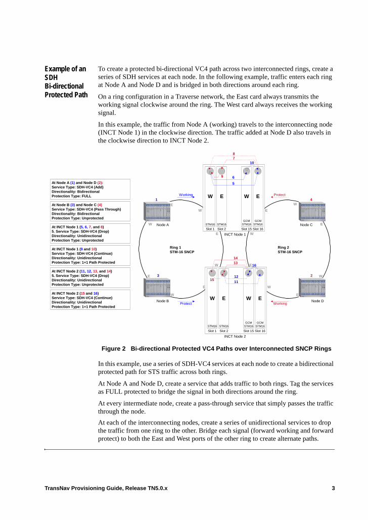
Example of an SDH Bi-directional Protected Path
To create a protected bi-directional VC4 path across two interconnected rings, create a series of SDH services at each node. In the following example, traffic enters each ring at Node A and Node D and is bridged in both directions around each ring.
On a ring configuration in a Traverse network, the East card always transmits the working signal clockwise around the ring. The West card always receives the working signal.
In this example, the traffic from Node A (working) travels to the interconnecting node (INCT Node 1) in the clockwise direction. The traffic added at Node D also travels in the clockwise direction to INCT Node 2.
Figure 2 Bi-directional Protected VC4 Paths over Interconnected SNCP Rings
In this example, use a series of SDH-VC4 services at each node to create a bidirectional protected path for STS traffic across both rings.
At Node A and Node D, create a service that adds traffic to both rings. Tag the services as FULL protected to bridge the signal in both directions around the ring.
At every intermediate node, create a pass-through service that simply passes the traffic through the node.
At each of the interconnecting nodes, create a series of unidirectional services to drop the traffic from one ring to the other. Bridge each signal (forward working and forward protect) to both the East and West ports of the other ring to create alternate paths.
W
Slot 2Slot 1
E
STM16STM16
Slot 16Slot 15
W E
GCMSTM16
GCMSTM16
W
INCT Node 1
Slot 2Slot 1
E
STM16STM16
Slot 16Slot 15
W E
GCMSTM16
GCMSTM16
5
6
10
9
INCT Node 2
161314
Node A
Node B Node D
Node C
1
3 2
4Working
Protect Working
Protect
78
11
1215
At Node B (3) and Node C (4)Service Type: SDH-VC4 (Pass Through)Directionality: BidirectionalProtection Type: Unprotected
At Node A (1) and Node D (2):Service Type: SDH-VC4 (Add)Directionality: BidirectionalProtection Type: FULL
At INCT Node 1 (9 and 10)Service Type: SDH-VC4 (Continue)Directionality: UnidirectionalProtection Type: 1+1 Path Protected
At INCT Node 1 (5, 6, 7, and 8)5. Service Type: SDH-VC4 (Drop)Directionality: UnidirectionalProtection Type: Unprotected
At INCT Node 2 (15 and 16)Service Type: SDH-VC4 (Continue)Directionality: UnidirectionalProtection Type: 1+1 Path Protected
At INCT Node 2 (11, 12, 13, and 14)5. Service Type: SDH-VC4 (Drop)Directionality: UnidirectionalProtection Type: Unprotected
E
W
W
E
E
W
E
W
W
W
W
E
E
E
W
E
Ring 1STM-16 SNCP
Ring 2STM-16 SNCP
TransNav Provisioning Guide, Release TN5.0.x 3

Example of Bi-directional Protected DS1 and VT1.5 Services
In the following example, DS1 traffic enters each ring at Node A and Node D and is bridged in both directions around each ring. The traffic from Node A (working) travels to INCT Node 1 in the clockwise direction. The traffic added at Node D travels in the clockwise direction to INCT Node 2.
Figure 3 Bi-directional DS1 and VT1.5 Services over Interconnected UPSR
In this example, create a combination of services: SONET-STS services and SONET-VT services to create a bi-directional path for DS1 channels across the rings. At Node A and Node D, create a service that adds traffic to both rings. Tag the services as FULL protected to bridge the signal in both directions around the ring.
At every intermediate node, create a pass-through service that simply passes the traffic through the node.
At each of the interconnecting nodes, create a series of unidirectional services to drop the traffic from one ring to the other. The incoming signal is a VT-mapped STS. Use a SONET-VT service to drop VTs to the second ring. Use a SONET-STS service to continue the VT-mapped STS to the next node to create an alternate path for the DS1 traffic.
5GVC/VT
5GVC/VT
5GVC/VT
5GVC/VT
W
W
Node A
Node B
Node C
Node D
INCT Node 2
Slot 2Slot 1
EW
OC12OC12
Slot 16Slot 15
W E
GCMOC48
GCMOC48
Slot 10Slot 9
INCT Node 1
Slot 2Slot 1
E
OC12OC12
Slot 16Slot 15
W E
GCMOC48
GCMOC48
Slot 10Slot 9
5
10
15
14
3
4Working
Protect Working
Protect
7
8
13
1
69
16
12
11
2
At Node A (1) and Node D (2):Service Type: DS1-Mux-VT (Add)Directionality: BidirectionalProtection Type: UPSR Protected
At INCT Node 1 (5, 6, 7, and 8)Service Type: SONET-VT (x 28) (Drop)Resource Advisory: OFFDirectionality: UnidirectionalProtection Type: UPSR Ingress
At Node B (3) and Node C (4):Service Type: SONET-STS (Pass Through)Directionality: BidirectionalProtection Type: Unprotected
At INCT Node 1 (9 and 10):Service Type: SONET-STS (Continue)Resource Advisory: OFFDirectionality: UnidirectionalProtection Type: Unprotected
At INCT Node 2 (11, 12, 13, and 14)Service Type: SONET-VT (x 28) (Drop)Resource Advisory: OFFDirectionality: UnidirectionalProtection Type: UPSR Ingress
At INCT Node 2 (15 and 16):Service Type: SONET-STS (Continue)Resource Advisory: OFFDirectionality: UnidirectionalProtection Type: Unprotected
E
W
W
E
E
W
E
W
W
W
E
E
EW
E
Ring 1OC-48 UPSR
Ring 2OC-48 UPSR
4 TransNav Provisioning Guide, Release TN5.0.x
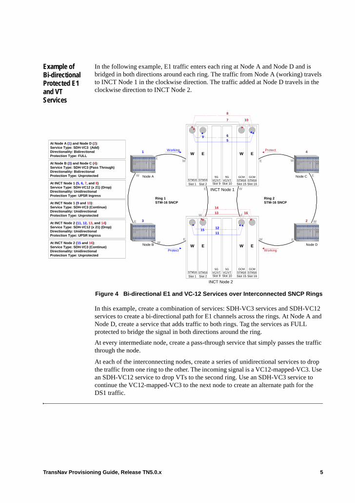
Example of Bi-directional Protected E1 and VT Services
In the following example, E1 traffic enters each ring at Node A and Node D and is bridged in both directions around each ring. The traffic from Node A (working) travels to INCT Node 1 in the clockwise direction. The traffic added at Node D travels in the clockwise direction to INCT Node 2.
Figure 4 Bi-directional E1 and VC-12 Services over Interconnected SNCP Rings
In this example, create a combination of services: SDH-VC3 services and SDH-VC12 services to create a bi-directional path for E1 channels across the rings. At Node A and Node D, create a service that adds traffic to both rings. Tag the services as FULL protected to bridge the signal in both directions around the ring.
At every intermediate node, create a pass-through service that simply passes the traffic through the node.
At each of the interconnecting nodes, create a series of unidirectional services to drop the traffic from one ring to the other. The incoming signal is a VC12-mapped-VC3. Use an SDH-VC12 service to drop VTs to the second ring. Use an SDH-VC3 service to continue the VC12-mapped-VC3 to the next node to create an alternate path for the DS1 traffic.
5GVC/VT
5GVC/VT
5GVC/VT
5GVC/VT
W
W
Node A
Node B
Node C
Node D
INCT Node 2
Slot 2Slot 1
EW
Slot 16Slot 15
W E
Slot 10Slot 9
INCT Node 1
Slot 2Slot 1
E
Slot 16Slot 15
W E
Slot 10Slot 9
5
10
15
14
3
4Working
Protect Working
Protect
7
8
13
1
69
16
12
11
2
At Node A (1) and Node D (2):Service Type: SDH-VC3 (Add)Directionality: BidirectionalProtection Type: FULL
At INCT Node 1 (5, 6, 7, and 8)Service Type: SDH-VC12 (x 21) (Drop)Directionality: UnidirectionalProtection Type: UPSR Ingress
At Node B (3) and Node C (4):Service Type: SDH-VC3 (Pass Through)Directionality: BidirectionalProtection Type: Unprotected
At INCT Node 1 (9 and 10):Service Type: SDH-VC3 (Continue)Directionality: UnidirectionalProtection Type: Unprotected
At INCT Node 2 (11, 12, 13, and 14)Service Type: SDH-VC12 (x 21) (Drop)Directionality: UnidirectionalProtection Type: UPSR Ingress
At INCT Node 2 (15 and 16):Service Type: SDH-VC3 (Continue)Directionality: UnidirectionalProtection Type: Unprotected
E
W
W
E
E
W
E
W
W
W
E
E
EW
E
Ring 1STM-16 SNCP
Ring 2STM-16 SNCP
GCMSTM16
GCMSTM16
GCMSTM16
GCMSTM16
STM16 STM16
STM16 STM16
TransNav Provisioning Guide, Release TN5.0.x 5
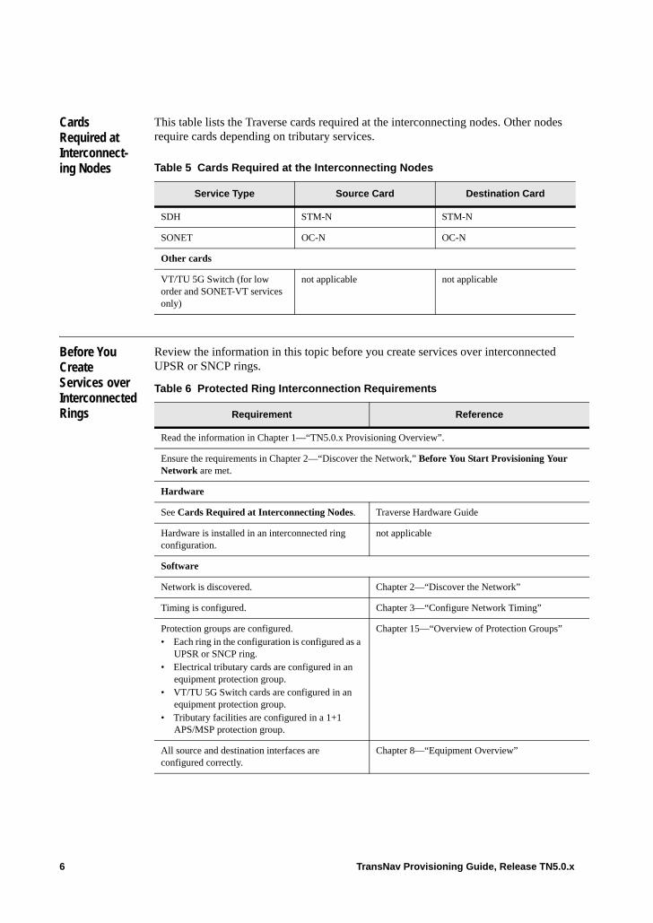
Cards Required at Interconnect-ing Nodes
This table lists the Traverse cards required at the interconnecting nodes. Other nodes require cards depending on tributary services.
Before You Create Services over Interconnected Rings
Review the information in this topic before you create services over interconnected UPSR or SNCP rings.
Table 5 Cards Required at the Interconnecting Nodes
Service Type Source Card Destination Card
SDH STM-N STM-N
SONET OC-N OC-N
Other cards
VT/TU 5G Switch (for low order and SONET-VT services only)
not applicable not applicable
Table 6 Protected Ring Interconnection Requirements
Requirement Reference
Read the information in Chapter 1—“TN5.0.x Provisioning Overview”.
Ensure the requirements in Chapter 2—“Discover the Network,” Before You Start Provisioning Your Network are met.
Hardware
See Cards Required at Interconnecting Nodes. Traverse Hardware Guide
Hardware is installed in an interconnected ring configuration.
not applicable
Software
Network is discovered. Chapter 2—“Discover the Network”
Timing is configured. Chapter 3—“Configure Network Timing”
Protection groups are configured.• Each ring in the configuration is configured as a
UPSR or SNCP ring.• Electrical tributary cards are configured in an
equipment protection group.• VT/TU 5G Switch cards are configured in an
equipment protection group.• Tributary facilities are configured in a 1+1
APS/MSP protection group.
Chapter 15—“Overview of Protection Groups”
All source and destination interfaces are configured correctly.
Chapter 8—“Equipment Overview”
6 TransNav Provisioning Guide, Release TN5.0.x
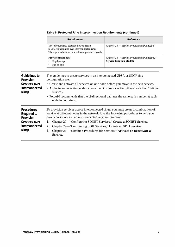
Guidelines to Provision Services over Interconnected Rings
The guidelines to create services in an interconnected UPSR or SNCP ring configuration are:• Create and activate all services on one node before you move to the next service.• At the interconnecting nodes, create the Drop services first, then create the Continue
services.• Force10 recommends that the bi-directional path use the same path number at each
node in both rings.
Procedures Required to Provision Services over Interconnected Rings
To provision services across interconnected rings, you must create a combination of service at different nodes in the network. Use the following procedures to help you provision services in an interconnected ring configuration:
1. Chapter 27—“Configuring SONET Services,” Create a SONET Service.
2. Chapter 29—“Configuring SDH Services,” Create an SDH Service.
3. Chapter 26—“Common Procedures for Services,” Activate or Deactivate a Service.
These procedures describe how to create bi-directional paths over interconnected rings. These procedures include relevant parameters only.
Chapter 24—“Service Provisioning Concepts”
Provisioning model • Hop-by-hop • End-to-end
Chapter 24—“Service Provisioning Concepts,” Service Creation Models
Table 6 Protected Ring Interconnection Requirements (continued)
Requirement Reference
TransNav Provisioning Guide, Release TN5.0.x 7

8 TransNav Provisioning Guide, Release TN5.0.x
Chapter 35 Creating Transmux Services
Introduction The optical transmux feature transforms incoming channelized DS3 signals to VC- or VT-mapped payloads on one node. Use this feature together with the VTX/VCX component or the VT/TU 5G Switch card to switch these payloads on the same node.
Note: For DCS-768 matrix shelves, use this feature with the UTMX48, 8-port OC-48 and VT-HD 40G Switch card to switch payloads on the same node.
This chapter explains how to create an optical transmux service in a Traverse network. • G.747 Services• Switching DS1s Inside a Channelized DS3• Switching E1s Inside a Channelized DS3• Cards Required to Create a Transmux Service• Before You Create a Transmux Service• Guidelines to Provision an Optical Transmux Service• Procedures Required to Provision an Optical Transmux Service• Assign and Configure Transmux Resources• Configure an Optical Transmux Service
If your system includes 2-port OC-48 cards, see Chapter 30—“Creating 2-Port OC-48/STM-16 Services” for additional information.
TransNav Provisioning Guide, Release TN5.0.x 1
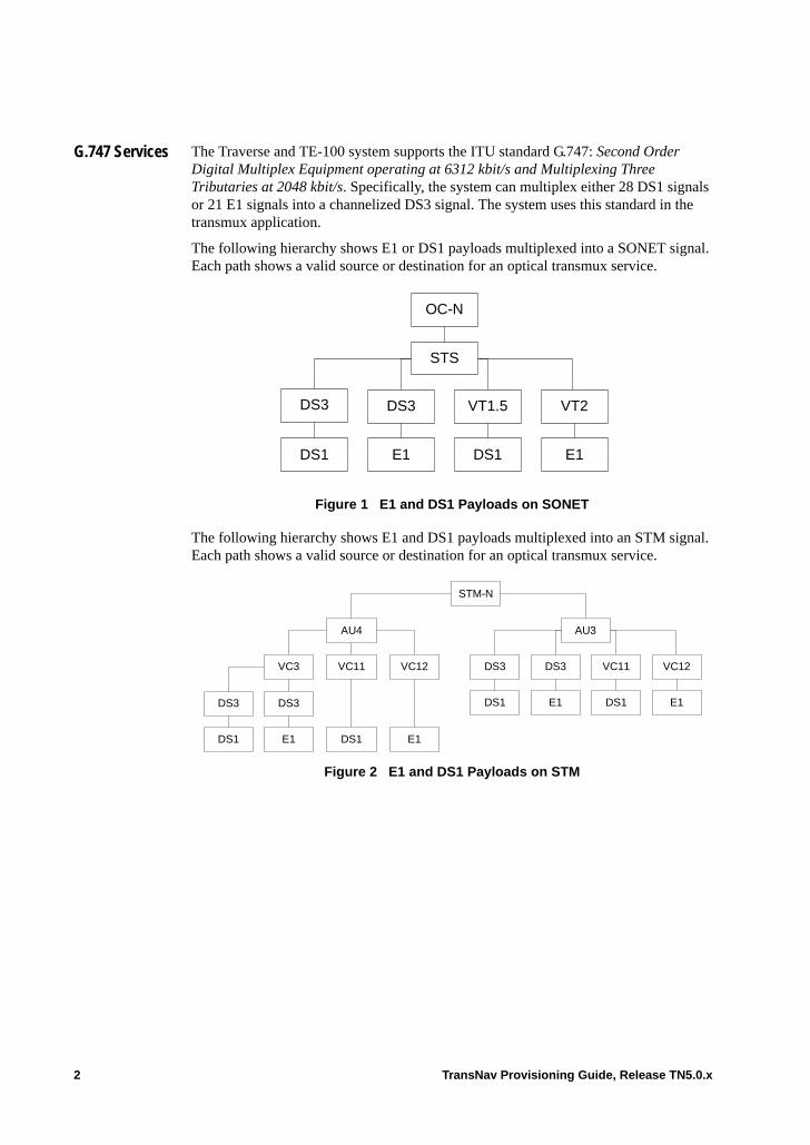
G.747 Services The Traverse and TE-100 system supports the ITU standard G.747: Second Order Digital Multiplex Equipment operating at 6312 kbit/s and Multiplexing Three Tributaries at 2048 kbit/s. Specifically, the system can multiplex either 28 DS1 signals or 21 E1 signals into a channelized DS3 signal. The system uses this standard in the transmux application.
The following hierarchy shows E1 or DS1 payloads multiplexed into a SONET signal. Each path shows a valid source or destination for an optical transmux service.
Figure 1 E1 and DS1 Payloads on SONET
The following hierarchy shows E1 and DS1 payloads multiplexed into an STM signal. Each path shows a valid source or destination for an optical transmux service.
Figure 2 E1 and DS1 Payloads on STM
OC-N
E1
STS
VT2
DS1
DS3
DS1
VT1.5DS3
E1
STM-N
DS1 E1
AU4
VC11 VC12VC3
DS1 E1
AU3
VC11 VC12DS3
DS1 E1
DS3
DS3
DS1 E1
DS3
2 TransNav Provisioning Guide, Release TN5.0.x
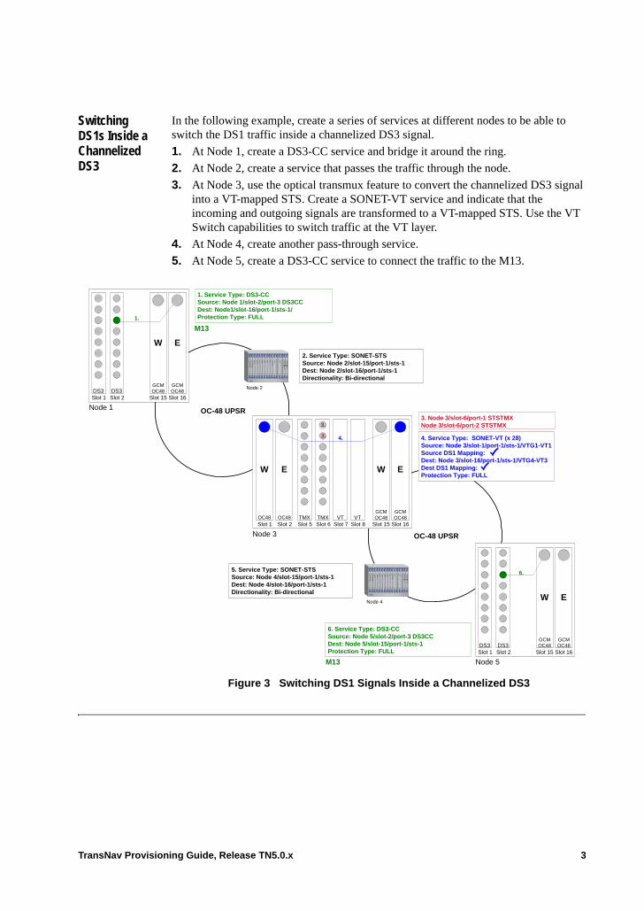
Switching DS1s Inside a Channelized DS3
In the following example, create a series of services at different nodes to be able to switch the DS1 traffic inside a channelized DS3 signal.
1. At Node 1, create a DS3-CC service and bridge it around the ring.
2. At Node 2, create a service that passes the traffic through the node.
3. At Node 3, use the optical transmux feature to convert the channelized DS3 signal into a VT-mapped STS. Create a SONET-VT service and indicate that the incoming and outgoing signals are transformed to a VT-mapped STS. Use the VT Switch capabilities to switch traffic at the VT layer.
4. At Node 4, create another pass-through service.
5. At Node 5, create a DS3-CC service to connect the traffic to the M13.
Figure 3 Switching DS1 Signals Inside a Channelized DS3
4. Service Type: SONET-VT (x 28)Source: Node 3/slot-1/port-1/sts-1/VTG1-VT1Source DS1 Mapping:Dest: Node 3/slot-16/port-1/sts-1/VTG4-VT3Dest DS1 Mapping:Protection Type: FULL
1. Service Type: DS3-CCSource: Node 1/slot-2/port-3 DS3CCDest: Node1/slot-16/port-1/sts-1/Protection Type: FULL
3. Node 3/slot-6/port-1 STSTMXNode 3/slot-6/port-2 STSTMX
6. Service Type: DS3-CCSource: Node 5/slot-2/port-3 DS3CCDest: Node 5/slot-15/port-1/sts-1Protection Type: FULL
Node 1
W E
GCMOC48
Slot 16
GCMOC48
Slot 15Slot 1DS3 DS3
Slot 2
Node 5
W E
GCMOC48
Slot 16
GCMOC48
Slot 15Slot 1DS3 DS3
Slot 2
OC-48 UPSR
OC-48 UPSR
W E
OC48Slot 1
Node 3
W E
GCMOC48
Slot 16
GCMOC48
Slot 15Slot 2 Slot 5TMX TMX VT VTOC48
Slot 6 Slot 7 Slot 8
1.
M13
3.
M13
4.
6.
Node 2
Node 4
2. Service Type: SONET-STSSource: Node 2/slot-15/port-1/sts-1Dest: Node 2/slot-16/port-1/sts-1Directionality: Bi-directional
5. Service Type: SONET-STSSource: Node 4/slot-15/port-1/sts-1Dest: Node 4/slot-16/port-1/sts-1Directionality: Bi-directional
3.
TransNav Provisioning Guide, Release TN5.0.x 3
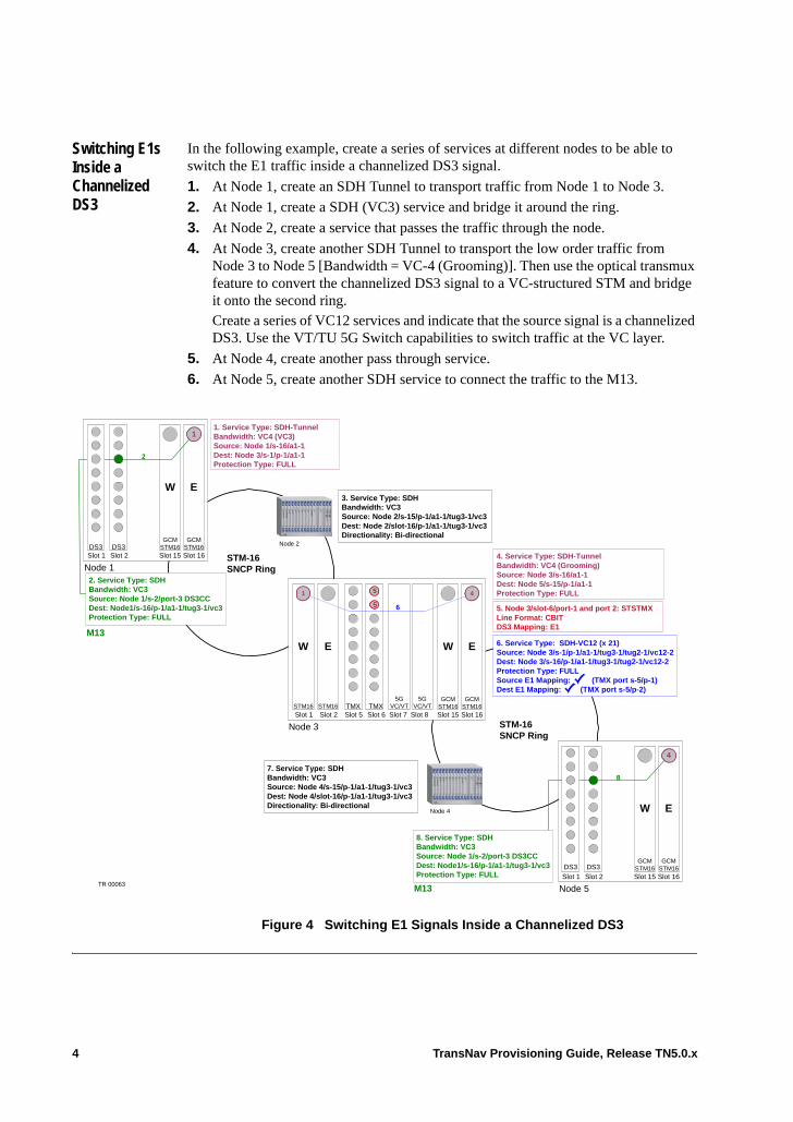
Switching E1s Inside a Channelized DS3
In the following example, create a series of services at different nodes to be able to switch the E1 traffic inside a channelized DS3 signal.
1. At Node 1, create an SDH Tunnel to transport traffic from Node 1 to Node 3.
2. At Node 1, create a SDH (VC3) service and bridge it around the ring.
3. At Node 2, create a service that passes the traffic through the node.
4. At Node 3, create another SDH Tunnel to transport the low order traffic from Node 3 to Node 5 [Bandwidth = VC-4 (Grooming)]. Then use the optical transmux feature to convert the channelized DS3 signal to a VC-structured STM and bridge it onto the second ring. Create a series of VC12 services and indicate that the source signal is a channelized DS3. Use the VT/TU 5G Switch capabilities to switch traffic at the VC layer.
5. At Node 4, create another pass through service.
6. At Node 5, create another SDH service to connect the traffic to the M13.
Figure 4 Switching E1 Signals Inside a Channelized DS3
5
5
5GVC/VT
5GVC/VT
6. Service Type: SDH-VC12 (x 21)Source: Node 3/s-1/p-1/a1-1/tug3-1/tug2-1/vc12-2Dest: Node 3/s-16/p-1/a1-1/tug3-1/tug2-1/vc12-2Protection Type: FULLSource E1 Mapping: (TMX port s-5/p-1)Dest E1 Mapping: (TMX port s-5/p-2)
5. Node 3/slot-6/port-1 and port 2: STSTMXLine Format: CBITDS3 Mapping: E1
STM-16SNCP Ring
W E
STM16
Slot 1
Node 3
W E
GCMSTM16Slot 16
GCMSTM16Slot 15Slot 2 Slot 5
TMX TMXSTM16
Slot 6 Slot 7 Slot 8
6
Node 2
Node 4
3. Service Type: SDHBandwidth: VC3Source: Node 2/s-15/p-1/a1-1/tug3-1/vc3Dest: Node 2/slot-16/p-1/a1-1/tug3-1/vc3Directionality: Bi-directional
1 4
STM-16SNCP Ring
4. Service Type: SDH-TunnelBandwidth: VC4 (Grooming)Source: Node 3/s-16/a1-1Dest: Node 5/s-15/p-1/a1-1Protection Type: FULL
7. Service Type: SDHBandwidth: VC3Source: Node 4/s-15/p-1/a1-1/tug3-1/vc3Dest: Node 4/slot-16/p-1/a1-1/tug3-1/vc3Directionality: Bi-directional
Node 1
W E
GCMSTM16Slot 16
GCMSTM16Slot 15Slot 1
DS3 DS3Slot 2
2
M13
11. Service Type: SDH-TunnelBandwidth: VC4 (VC3)Source: Node 1/s-16/a1-1Dest: Node 3/s-1/p-1/a1-1Protection Type: FULL
2. Service Type: SDHBandwidth: VC3Source: Node 1/s-2/port-3 DS3CCDest: Node1/s-16/p-1/a1-1/tug3-1/vc3Protection Type: FULL
Node 5
W E
GCMSTM16Slot 16
GCMSTM16Slot 15Slot 1
DS3 DS3Slot 2
8
M13
4
DS3
8. Service Type: SDHBandwidth: VC3Source: Node 1/s-2/port-3 DS3CCDest: Node1/s-16/p-1/a1-1/tug3-1/vc3Protection Type: FULL
DS3
DS3
TR 00063
4 TransNav Provisioning Guide, Release TN5.0.x
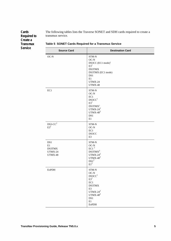
Cards Required to Create a Transmux Service
The following tables lists the Traverse SONET and SDH cards required to create a transmux service.
Table 5 SONET Cards Required for a Transmux Service
Source Card Destination Card
OC-N STM-NOC-NDS3CC (EC1 mode)1
E31
DS3TMXDS3TMX (EC1 mode)DS1E1UTMX-24UTMX-48
EC1 STM-NOC-NEC1DS3CC1 E31
DS3TMX2
UTMX-242
UTMX-482
DS1E1
DS3-CC1
E31STM-NOC-NEC1DS3CCE3
DS1 E1 DS3TMX UTMX-24UTMX-48
STM-NOC-NEC1 2
DS3TMX2
UTMX-242
UTMX-482
DS12
E12
EoPDH STM-NOC-NDS3CC1
E31
EC1DS3TMXE3UTMX-242
UTMX-482 DS1E1EoPDH
TransNav Provisioning Guide, Release TN5.0.x 5
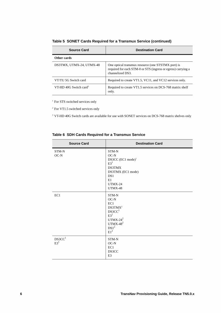
Other cards
DS3TMX, UTMX-24, UTMX-48 One optical transmux resource (one STSTMX port) is required for each STM-0 or STS (ingress or egress) carrying a channelized DS3.
VT/TU 5G Switch card Required to create VT1.5, VC11, and VC12 services only.
VT-HD 40G Switch card3 Required to create VT1.5 services on DCS-768 matrix shelf only.
1 For STS switched services only
2 For VT1.5 switched services only
3 VT-HD 40G Switch cards are available for use with SONET services on DCS-768 matrix shelves only
Table 6 SDH Cards Required for a Transmux Service
Source Card Destination Card
STM-NOC-N
STM-NOC-NDS3CC (EC1 mode)1
E31
DS3TMX DS3TMX (EC1 mode)DS1E1UTMX-24UTMX-48
EC1 STM-NOC-NEC1DS3TMX2 DS3CC1
E31 UTMX-242
UTMX-482
DS12
E12
DS3CC1
E31STM-NOC-NEC1DS3CCE3
Table 5 SONET Cards Required for a Transmux Service (continued)
Source Card Destination Card
6 TransNav Provisioning Guide, Release TN5.0.x
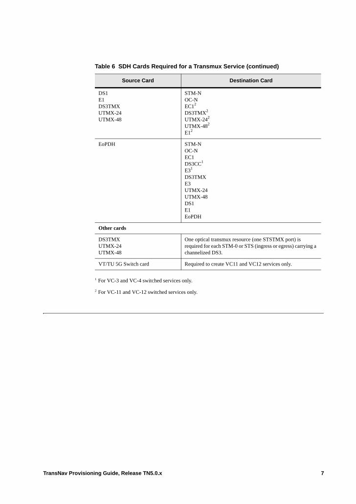
DS1 E1 DS3TMX UTMX-24UTMX-48
STM-NOC-NEC12
DS3TMX2 UTMX-242
UTMX-482
E12
EoPDH STM-NOC-NEC1DS3CC1
E31
DS3TMXE3UTMX-24UTMX-48DS1E1EoPDH
Other cards
DS3TMXUTMX-24UTMX-48
One optical transmux resource (one STSTMX port) is required for each STM-0 or STS (ingress or egress) carrying a channelized DS3.
VT/TU 5G Switch card Required to create VC11 and VC12 services only.
1 For VC-3 and VC-4 switched services only.
2 For VC-11 and VC-12 switched services only.
Table 6 SDH Cards Required for a Transmux Service (continued)
Source Card Destination Card
TransNav Provisioning Guide, Release TN5.0.x 7
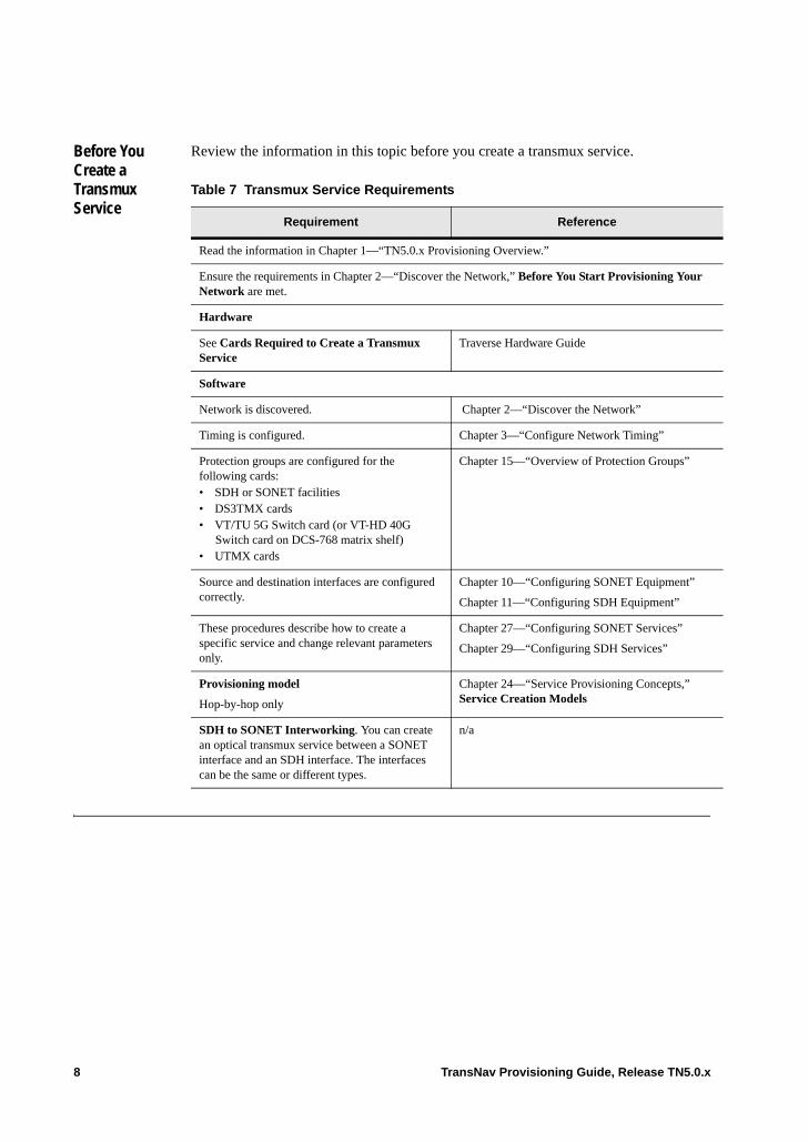
Before You Create a Transmux Service
Review the information in this topic before you create a transmux service.
Table 7 Transmux Service Requirements
Requirement Reference
Read the information in Chapter 1—“TN5.0.x Provisioning Overview.”
Ensure the requirements in Chapter 2—“Discover the Network,” Before You Start Provisioning Your Network are met.
Hardware
See Cards Required to Create a Transmux Service
Traverse Hardware Guide
Software
Network is discovered. Chapter 2—“Discover the Network”
Timing is configured. Chapter 3—“Configure Network Timing”
Protection groups are configured for the following cards:• SDH or SONET facilities• DS3TMX cards• VT/TU 5G Switch card (or VT-HD 40G
Switch card on DCS-768 matrix shelf)• UTMX cards
Chapter 15—“Overview of Protection Groups”
Source and destination interfaces are configured correctly.
Chapter 10—“Configuring SONET Equipment”
Chapter 11—“Configuring SDH Equipment”
These procedures describe how to create a specific service and change relevant parameters only.
Chapter 27—“Configuring SONET Services”
Chapter 29—“Configuring SDH Services”
Provisioning model
Hop-by-hop only
Chapter 24—“Service Provisioning Concepts,” Service Creation Models
SDH to SONET Interworking. You can create an optical transmux service between a SONET interface and an SDH interface. The interfaces can be the same or different types.
n/a
8 TransNav Provisioning Guide, Release TN5.0.x
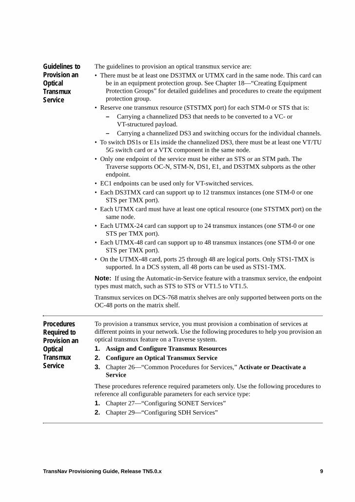
Guidelines to Provision an Optical Transmux Service
The guidelines to provision an optical transmux service are:• There must be at least one DS3TMX or UTMX card in the same node. This card can
be in an equipment protection group. See Chapter 18—“Creating Equipment Protection Groups” for detailed guidelines and procedures to create the equipment protection group.
• Reserve one transmux resource (STSTMX port) for each STM-0 or STS that is:– Carrying a channelized DS3 that needs to be converted to a VC- or
VT-structured payload.– Carrying a channelized DS3 and switching occurs for the individual channels.
• To switch DS1s or E1s inside the channelized DS3, there must be at least one VT/TU 5G switch card or a VTX component in the same node.
• Only one endpoint of the service must be either an STS or an STM path. The Traverse supports OC-N, STM-N, DS1, E1, and DS3TMX subports as the other endpoint.
• EC1 endpoints can be used only for VT-switched services.• Each DS3TMX card can support up to 12 transmux instances (one STM-0 or one
STS per TMX port). • Each UTMX card must have at least one optical resource (one STSTMX port) on the
same node.• Each UTMX-24 card can support up to 24 transmux instances (one STM-0 or one
STS per TMX port).• Each UTMX-48 card can support up to 48 transmux instances (one STM-0 or one
STS per TMX port). • On the UTMX-48 card, ports 25 through 48 are logical ports. Only STS1-TMX is
supported. In a DCS system, all 48 ports can be used as STS1-TMX.
Note: If using the Automatic-in-Service feature with a transmux service, the endpoint types must match, such as STS to STS or VT1.5 to VT1.5.
Transmux services on DCS-768 matrix shelves are only supported between ports on the OC-48 ports on the matrix shelf.
Procedures Required to Provision an Optical Transmux Service
To provision a transmux service, you must provision a combination of services at different points in your network. Use the following procedures to help you provision an optical transmux feature on a Traverse system.
1. Assign and Configure Transmux Resources
2. Configure an Optical Transmux Service
3. Chapter 26—“Common Procedures for Services,” Activate or Deactivate a Service
These procedures reference required parameters only. Use the following procedures to reference all configurable parameters for each service type:
1. Chapter 27—“Configuring SONET Services”
2. Chapter 29—“Configuring SDH Services”
TransNav Provisioning Guide, Release TN5.0.x 9
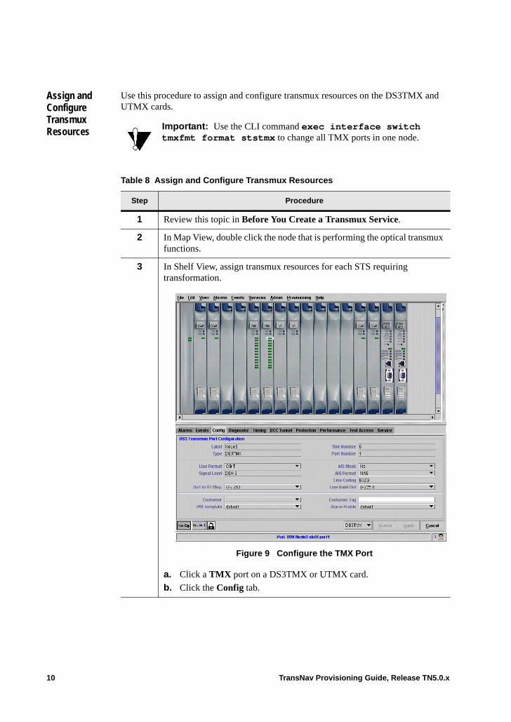
Assign and Configure Transmux Resources
Use this procedure to assign and configure transmux resources on the DS3TMX and UTMX cards.
Important: Use the CLI command exec interface switch tmxfmt format ststmx to change all TMX ports in one node.
Table 8 Assign and Configure Transmux Resources
Step Procedure
1 Review this topic in Before You Create a Transmux Service.
2 In Map View, double click the node that is performing the optical transmux functions.
3 In Shelf View, assign transmux resources for each STS requiring transformation.
Figure 9 Configure the TMX Port
a. Click a TMX port on a DS3TMX or UTMX card.
b. Click the Config tab.
10 TransNav Provisioning Guide, Release TN5.0.x
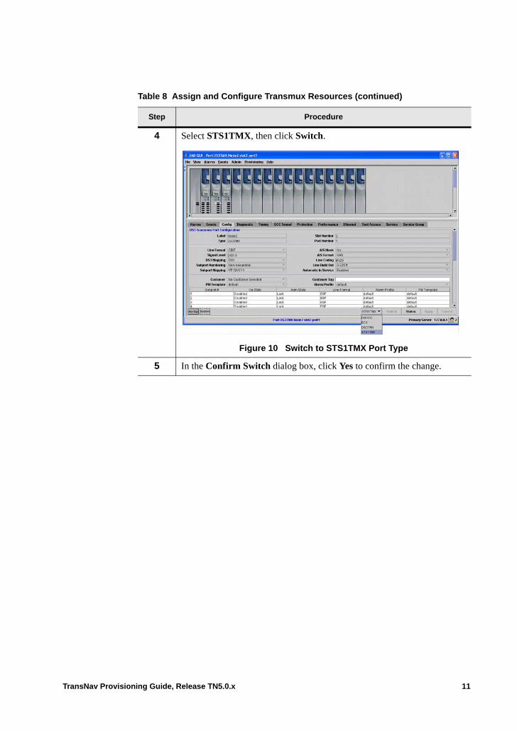
4 Select STS1TMX, then click Switch.
Figure 10 Switch to STS1TMX Port Type
5 In the Confirm Switch dialog box, click Yes to confirm the change.
Table 8 Assign and Configure Transmux Resources (continued)
Step Procedure
TransNav Provisioning Guide, Release TN5.0.x 11
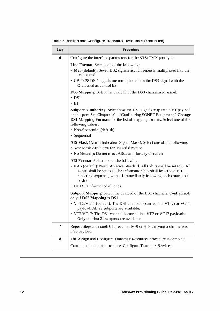
6 Configure the interface parameters for the STS1TMX port type:
Line Format: Select one of the following:• M23 (default): Seven DS2 signals asynchronously multiplexed into the
DS3 signal.• CBIT: 28 DS-1 signals are multiplexed into the DS3 signal with the
C-bit used as control bit.
DS3 Mapping: Select the payload of the DS3 channelized signal:• DS1• E1
Subport Numbering: Select how the DS1 signals map into a VT payload on this port. See Chapter 10—“Configuring SONET Equipment,” Change DS1 Mapping Formats for the list of mapping formats. Select one of the following values: • Non-Sequential (default)• Sequential
AIS Mask (Alarm Indication Signal Mask): Select one of the following:• Yes: Mask AIS/alarm for unused direction• No (default): Do not mask AIS/alarm for any direction
AIS Format: Select one of the following:• NAS (default): North America Standard. All C-bits shall be set to 0. All
X-bits shall be set to 1. The information bits shall be set to a 1010... repeating sequence, with a 1 immediately following each control bit position.
• ONES: Unformatted all ones.
Subport Mapping: Select the payload of the DS1 channels. Configurable only if DS3 Mapping is DS1.• VT1.5/VC11 (default): The DS1 channel is carried in a VT1.5 or VC11
payload. All 28 subports are available.• VT2/VC12: The DS1 channel is carried in a VT2 or VC12 payloads.
Only the first 21 subports are available.
7 Repeat Steps 3 through 6 for each STM-0 or STS carrying a channelized DS3 payload.
8 The Assign and Configure Transmux Resources procedure is complete.
Continue to the next procedure, Configure Transmux Services.
Table 8 Assign and Configure Transmux Resources (continued)
Step Procedure
12 TransNav Provisioning Guide, Release TN5.0.x
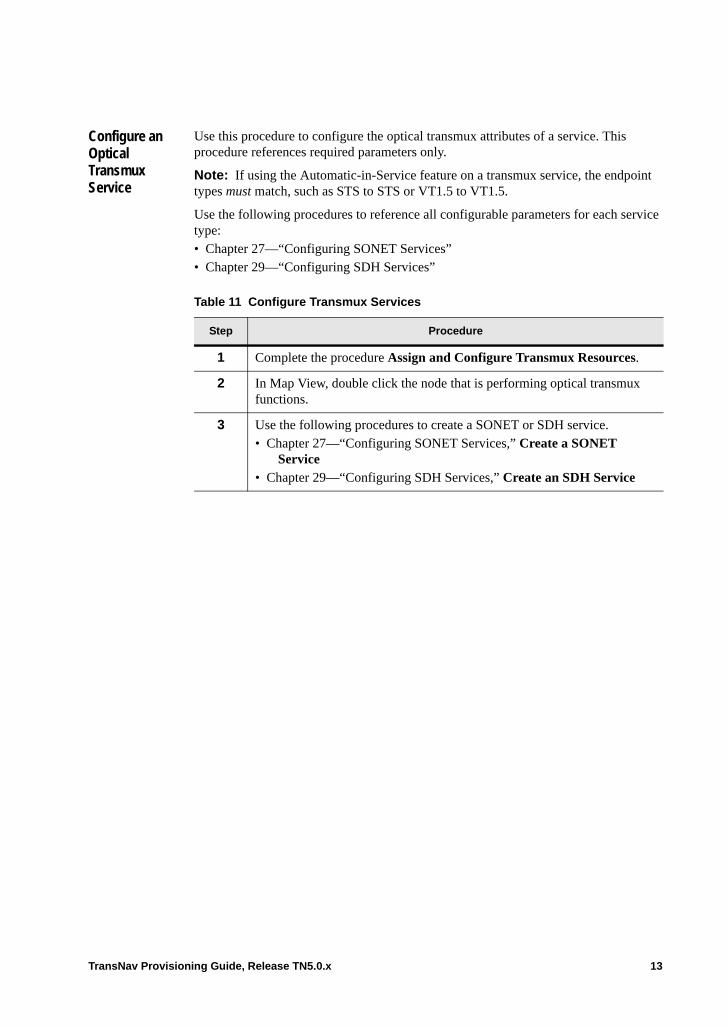
Configure an Optical Transmux Service
Use this procedure to configure the optical transmux attributes of a service. This procedure references required parameters only.
Note: If using the Automatic-in-Service feature on a transmux service, the endpoint types must match, such as STS to STS or VT1.5 to VT1.5.
Use the following procedures to reference all configurable parameters for each service type:• Chapter 27—“Configuring SONET Services”• Chapter 29—“Configuring SDH Services”
Table 11 Configure Transmux Services
Step Procedure
1 Complete the procedure Assign and Configure Transmux Resources.
2 In Map View, double click the node that is performing optical transmux functions.
3 Use the following procedures to create a SONET or SDH service. • Chapter 27—“Configuring SONET Services,” Create a SONET
Service• Chapter 29—“Configuring SDH Services,” Create an SDH Service
TransNav Provisioning Guide, Release TN5.0.x 13
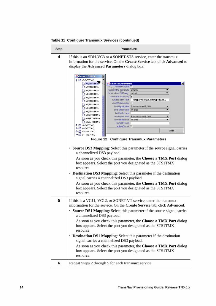
4 If this is an SDH-VC3 or a SONET-STS service, enter the transmux information for the service. On the Create Service tab, click Advanced to display the Advanced Parameters dialog box.
Figure 12 Configure Transmux Parameters
• Source DS3 Mapping: Select this parameter if the source signal carries a channelized DS3 payload.As soon as you check this parameter, the Choose a TMX Port dialog box appears. Select the port you designated as the STS1TMX resource.
• Destination DS3 Mapping: Select this parameter if the destination signal carries a channelized DS3 payload.As soon as you check this parameter, the Choose a TMX Port dialog box appears. Select the port you designated as the STS1TMX resource.
5 If this is a VC11, VC12, or SONET-VT service, enter the transmux information for the service. On the Create Service tab, click Advanced.• Source DS1 Mapping: Select this parameter if the source signal carries
a channelized DS3 payload.As soon as you check this parameter, the Choose a TMX Port dialog box appears. Select the port you designated as the STS1TMX resource.
• Destination DS1 Mapping: Select this parameter if the destination signal carries a channelized DS3 payload.As soon as you check this parameter, the Choose a TMX Port dialog box appears. Select the port you designated as the STS1TMX resource.
6 Repeat Steps 2 through 5 for each transmux service
Table 11 Configure Transmux Services (continued)
Step Procedure
14 TransNav Provisioning Guide, Release TN5.0.x

7 To activate the services, see Chapter 26—“Common Procedures for Services,” Activate or Deactivate a Service and complete the procedure.
8 The Configure an Optical Transmux Service procedure is complete.
Table 11 Configure Transmux Services (continued)
Step Procedure
TransNav Provisioning Guide, Release TN5.0.x 15

16 TransNav Provisioning Guide, Release TN5.0.x
Chapter 36 Creating Transparent Services
Introduction This chapter explains how to create a transparent service in a Traverse network. • Example of SONET Transparent Services• Example of SDH Transparent Services• Cards Required to Create a Transparent Service• Before You Create a Transparent Service• Guidelines to Provision Transparent Services• Procedures Required to Create a Transparent Service• Disable Control Data Parameter on Nodes Linked to Third-Party Equipment• Provision the Transparent Service
If your system includes 2-port OC-48 cards, see Chapter 30—“Creating 2-Port OC-48/STM-16 Services” for additional information.
TransNav Provisioning Guide, Release TN5.0.x 1
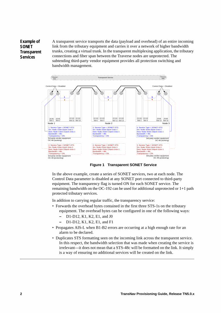
Example of SONET Transparent Services
A transparent service transports the data (payload and overhead) of an entire incoming link from the tributary equipment and carries it over a network of higher bandwidth trunks, creating a virtual trunk. In the transparent multiplexing application, the tributary connections and fiber span between the Traverse nodes are unprotected. The subtending third-party vendor equipment provides all protection switching and bandwidth management.
Figure 1 Transparent SONET Service
In the above example, create a series of SONET services, two at each node. The Control Data parameter is disabled at any SONET port connected to third-party equipment. The transparency flag is turned ON for each SONET service. The remaining bandwidth on the OC-192 can be used for additional unprotected or 1+1 path protected tributary services.
In addition to carrying regular traffic, the transparency service:• Forwards the overhead bytes contained in the first three STS-1s on the tributary
equipment. The overhead bytes can be configured in one of the following ways:– D1-D12, K1, K2, E1, and J0– D1-D12, K1, K2, E1, and F1
• Propagates AIS-L when B1-B2 errors are occurring at a high enough rate for an alarm to be declared.
• Duplicates STS formatting seen on the incoming link across the transparent service. In this respect, the bandwidth selection that was made when creating the service is irrelevant—it does not mean that a STS-48c will be formatted on the link. It simply is a way of ensuring no additional services will be created on the link.
3rd party vendor equipmentOC-48 (working)
3rd party vendor equipmentOC-48 (protecting)
3rd party vendor equipmentOC-48 (working)
3rd party vendor equipmentOC-48 (protecting)
Slot 1 Slot 11Slot 3 Slot 13
Node 1
Slot 13OC48
Slot 2OC48
Slot 1 Slot 11
1
Node 2
Slot 1OC48
Slot 13Slot 3OC48
Slot 14
6
Control Data = DisabledControl Data = Disabled
OC192 OC192 OC192 OC192OC192OC192 OC192 OC192
2 4
3 5
1. Service Type = SONET-STSSrc: Node 1/slot-2/port-1/sts-1Dest: Node 1/slot-11/port-1/sts-1Bandwidth = 48cTransparency = ON
2. Service Type = SONET-STSSrc: Node 1/slot-1/port-1/sts-1Dest: Node 1/slot-13/port-1/sts-1Bandwidth = 48cTransparency = ON
3. Service Type = SONET-STSSrc: Node 2/slot-3/port-1/sts-1Dest: Node 2/slot-11/port-1/sts-1Bandwidth = 48cTransparency = ON
4. Service Type = SONET-STSSrc: Node 2/slot-1/port-1/sts-1Dest: Node 2/slot-13/port-1/sts-1Bandwidth = 48cTransparency = ON
3. Service Type = SONET-STSSrc: Node 3/slot-1/port-1/sts-1Dest: Node 3/slot-14/port-1/sts-1Bandwidth = 48cTransparency = ON
4. Service Type = SONET-STSSrc: Node 3/slot-3/port-1/sts-1Dest: Node 3/slot-13/port-1/sts-1Bandwidth = 48cTransparency = ON
Node 3
Transparent ServiceTributarydata
Tributarydata
2 TransNav Provisioning Guide, Release TN5.0.x
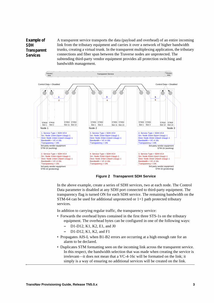
Example of SDH Transparent Services
A transparent service transports the data (payload and overhead) of an entire incoming link from the tributary equipment and carries it over a network of higher bandwidth trunks, creating a virtual trunk. In the transparent multiplexing application, the tributary connections and fiber span between the Traverse nodes are unprotected. The subtending third-party vendor equipment provides all protection switching and bandwidth management.
Figure 2 Transparent SDH Service
In the above example, create a series of SDH services, two at each node. The Control Data parameter is disabled at any SDH port connected to third-party equipment. The transparency flag is turned ON for each SDH service. The remaining bandwidth on the STM-64 can be used for additional unprotected or 1+1 path protected tributary services.
In addition to carrying regular traffic, the transparency service:• Forwards the overhead bytes contained in the first three STS-1s on the tributary
equipment. The overhead bytes can be configured in one of the following ways:– D1-D12, K1, K2, E1, and J0– D1-D12, K1, K2, and F1
• Propagates AIS-L when B1-B2 errors are occurring at a high enough rate for an alarm to be declared.
• Duplicates STM formatting seen on the incoming link across the transparent service. In this respect, the bandwidth selection that was made when creating the service is irrelevant—it does not mean that a VC-4-16c will be formatted on the link; it simply is a way of ensuring no additional services will be created on the link.
3rd party vendor equipmentSTM-16 (working)
3rd party vendor equipmentSTM-16 (protecting)
3rd party vendor equipmentSTM-16 (working)
3rd party vendor equipmentSTM-16 (protecting)
Slot 1 Slot 11Slot 3 Slot 13
Node 1
Slot 13STM16
Slot 2STM16
Slot 1 Slot 11
1
Node 3
Slot 1STM16
Slot 13Slot 3STM16
Slot 14
6
Control Data = DisabledControl Data = Disabled
STM64 STM64 STM64 STM64STM64STM64 STM64 STM64
2 4
3 5
1. Service Type = SDH-VC4Src: Node 1/slot-2/port-1/aug1-1Dest: Node 1/slot-11/port-1/aug1-1Bandwidth = VC-4-16cTransparency = ON
2. Service Type = SDH-VC4Src: Node 1/slot-1/port-1/aug1-1Dest: Node 1/slot-13/port-1/aug1-1Bandwidth = VC-4-16cTransparency = ON
3. Service Type = SDH-VC4Src: Node 2/slot-3/port-1/aug1-1Dest: Node 2/slot-11/port-1/aug1-1Bandwidth = VC-4-16cTransparency = ON
4. Service Type = SDH-VC4Src: Node 2/slot-1/port-1/aug1-1Dest: Node 2/slot-13/port-1/aug1-1Bandwidth = VC-4-16cTransparency = ON
3. Service Type = SDH-VC4Src: Node 3/slot-1/port-1/aug1-1Dest: Node 3/slot-14/port-1/aug1-1Bandwidth = VC-4-16cTransparency = ON
4. Service Type = SDH-VC4Src: Node 3/slot-3/port-1/aug1-1Dest: Node 3/slot-13/port-1/aug1-1Bandwidth = VC-4-16cTransparency = ON
Node 2
Transparent ServiceTributarydata
Tributarydata
TransNav Provisioning Guide, Release TN5.0.x 3
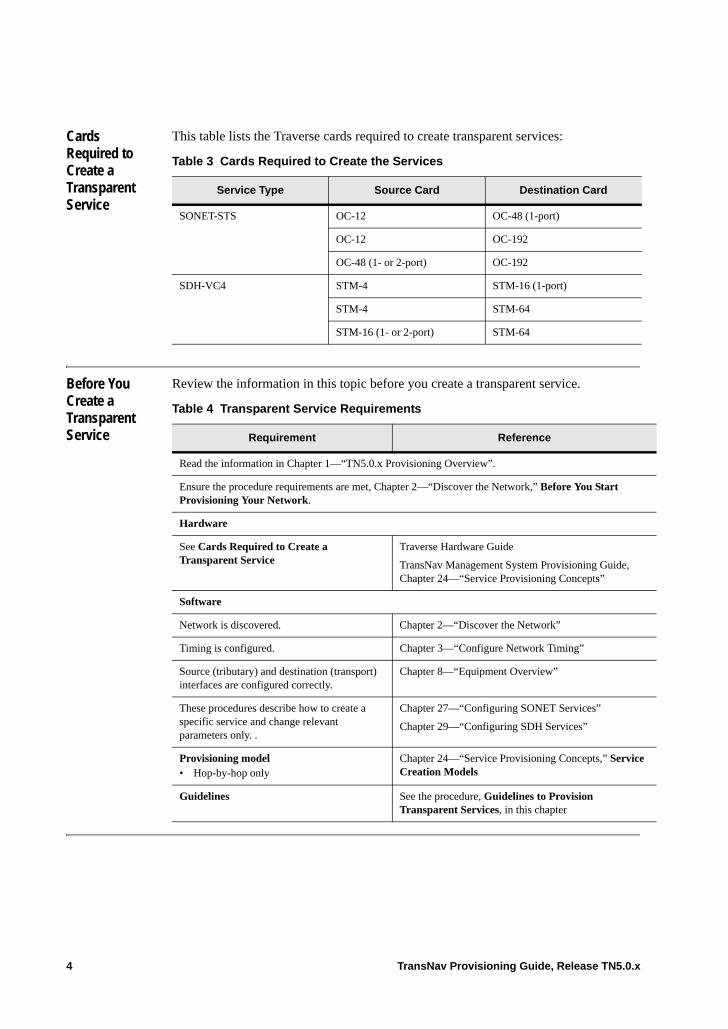
Cards Required to Create a Transparent Service
This table lists the Traverse cards required to create transparent services:
Before You Create a Transparent Service
Review the information in this topic before you create a transparent service.
Table 3 Cards Required to Create the Services
Service Type Source Card Destination Card
SONET-STS OC-12 OC-48 (1-port)
OC-12 OC-192
OC-48 (1- or 2-port) OC-192
SDH-VC4 STM-4 STM-16 (1-port)
STM-4 STM-64
STM-16 (1- or 2-port) STM-64
Table 4 Transparent Service Requirements
Requirement Reference
Read the information in Chapter 1—“TN5.0.x Provisioning Overview”.
Ensure the procedure requirements are met, Chapter 2—“Discover the Network,” Before You Start Provisioning Your Network.
Hardware
See Cards Required to Create a Transparent Service
Traverse Hardware Guide
TransNav Management System Provisioning Guide, Chapter 24—“Service Provisioning Concepts”
Software
Network is discovered. Chapter 2—“Discover the Network”
Timing is configured. Chapter 3—“Configure Network Timing”
Source (tributary) and destination (transport) interfaces are configured correctly.
Chapter 8—“Equipment Overview”
These procedures describe how to create a specific service and change relevant parameters only. .
Chapter 27—“Configuring SONET Services”
Chapter 29—“Configuring SDH Services”
Provisioning model• Hop-by-hop only
Chapter 24—“Service Provisioning Concepts,” Service Creation Models
Guidelines See the procedure, Guidelines to Provision Transparent Services, in this chapter
4 TransNav Provisioning Guide, Release TN5.0.x

Guidelines to Provision Transparent Services
The guidelines to provision a transparent service are:• For protected configurations, there must be two tributary and two trunk cards on each
node transporting the transparent service.• You can use the following combinations of interfaces in a transparent service:
– STM-4 tributary and 1-port STM-16 trunks– STM-4 tributary and STM-64 trunks– 1-port STM-16 tributary and STM-64 trunks– 2-port STM-16 tributary and STM-64 trunks– OC-12 tributary and 1-port OC-48 trunks– OC-12 tributary and OC-192 trunks– 1-port OC-48 tributary and OC-192 trunks– 2-port OC-48 tributary and OC-192 trunks
• The Traverse system supports transparent services over an OC-192/STM-64 or 1-port OC-48/STM-16 linear chain.
• There can be no other services provisioned on the tributary port.• The remaining bandwidth on the trunk cards can be used for additional unprotected
or 1+1 path protected services.• The tributary connections and fiber span between the Traverse nodes are unprotected.
The subtending third-party equipment provides all protection switching and bandwidth management.
For 2-port OC-48 cards, the following guidelines also apply:• All services from one 2-port OC-48 card must use a contiguous set of 48 STS paths
on the OC-192 card. On the 2-slot OC-192 card, STS-1 to STS-96 are available in the lower-numbered slot. STS-97 to STS-192 are available in the higher-numbered slot.
• The slot-to-slot switching architecture is non-blocking for all SONET cards except the 2-port OC-48 card. Do not exceed the slot-to-slot bandwidth capacity of 48 STSs when establishing services between the cards.
• Force10 does not support the use of 2-port OC-48 cards for carrying OC-12 transparency services.
For information on creating services using 2-port OC-48 or STM-16 cards, see Chapter 30—“Creating 2-Port OC-48/STM-16 Services.”
TransNav Provisioning Guide, Release TN5.0.x 5
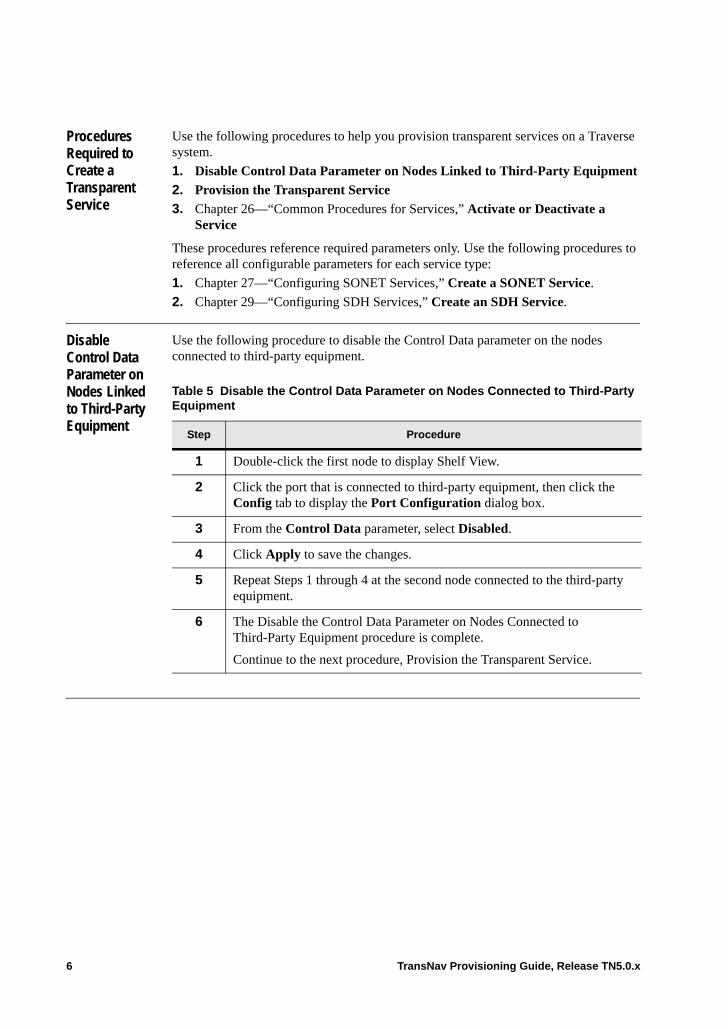
Procedures Required to Create a Transparent Service
Use the following procedures to help you provision transparent services on a Traverse system.
1. Disable Control Data Parameter on Nodes Linked to Third-Party Equipment
2. Provision the Transparent Service
3. Chapter 26—“Common Procedures for Services,” Activate or Deactivate a Service
These procedures reference required parameters only. Use the following procedures to reference all configurable parameters for each service type:
1. Chapter 27—“Configuring SONET Services,” Create a SONET Service.
2. Chapter 29—“Configuring SDH Services,” Create an SDH Service.
Disable Control Data Parameter on Nodes Linked to Third-Party Equipment
Use the following procedure to disable the Control Data parameter on the nodes connected to third-party equipment.
Table 5 Disable the Control Data Parameter on Nodes Connected to Third-Party Equipment
Step Procedure
1 Double-click the first node to display Shelf View.
2 Click the port that is connected to third-party equipment, then click the Config tab to display the Port Configuration dialog box.
3 From the Control Data parameter, select Disabled.
4 Click Apply to save the changes.
5 Repeat Steps 1 through 4 at the second node connected to the third-party equipment.
6 The Disable the Control Data Parameter on Nodes Connected to Third-Party Equipment procedure is complete.
Continue to the next procedure, Provision the Transparent Service.
6 TransNav Provisioning Guide, Release TN5.0.x
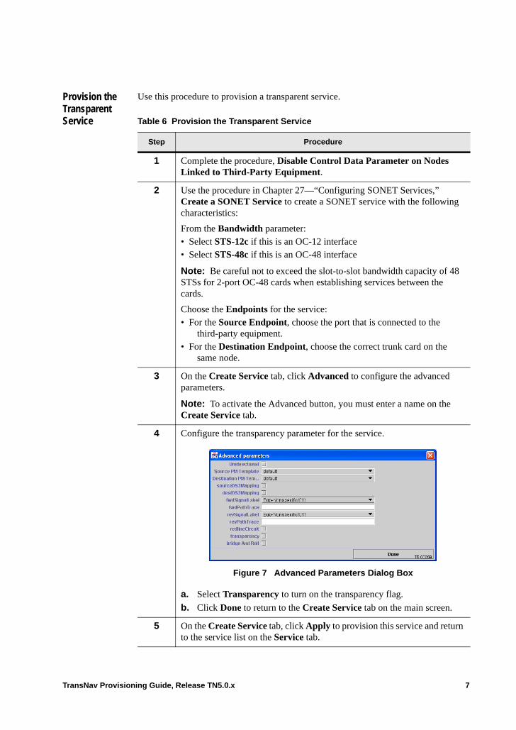
Provision the Transparent Service
Use this procedure to provision a transparent service.
Table 6 Provision the Transparent Service
Step Procedure
1 Complete the procedure, Disable Control Data Parameter on Nodes Linked to Third-Party Equipment.
2 Use the procedure in Chapter 27—“Configuring SONET Services,” Create a SONET Service to create a SONET service with the following characteristics:
From the Bandwidth parameter:• Select STS-12c if this is an OC-12 interface• Select STS-48c if this is an OC-48 interface
Note: Be careful not to exceed the slot-to-slot bandwidth capacity of 48 STSs for 2-port OC-48 cards when establishing services between the cards.
Choose the Endpoints for the service: • For the Source Endpoint, choose the port that is connected to the
third-party equipment.• For the Destination Endpoint, choose the correct trunk card on the
same node.
3 On the Create Service tab, click Advanced to configure the advanced parameters.
Note: To activate the Advanced button, you must enter a name on the Create Service tab.
4 Configure the transparency parameter for the service.
Figure 7 Advanced Parameters Dialog Box
a. Select Transparency to turn on the transparency flag.
b. Click Done to return to the Create Service tab on the main screen.
5 On the Create Service tab, click Apply to provision this service and return to the service list on the Service tab.
TransNav Provisioning Guide, Release TN5.0.x 7
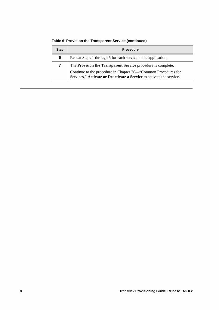
6 Repeat Steps 1 through 5 for each service in the application.
7 The Provision the Transparent Service procedure is complete.
Continue to the procedure in Chapter 26—“Common Procedures for Services,” Activate or Deactivate a Service to activate the service.
Table 6 Provision the Transparent Service (continued)
Step Procedure
8 TransNav Provisioning Guide, Release TN5.0.x
Chapter 37 DCS Application Overview
Introduction Digital Cross-connect Services (DCS) are the cross-connects in a SONET-only network that switch the VT1.5 signals on the DCS switching shelves: DCS-768,DCS-384, and DCS-96. Use a DCS implementation when a large number of low order services need to be switched.
This chapter introduces the following Traverse DCS applications:• Multi-Shelf DCS Network Example• DCS-384 Matrix Shelf• DCS-768 Matrix Shelf• DCS-IO Shelf• Single-Shelf DCS Application Example• DCS-96 Shelf• MSAID on DCS• MSAID Allocation• MSAID Assignments• MSAID Formats
TransNav Provisioning Guide, Release TN5.0.x 1
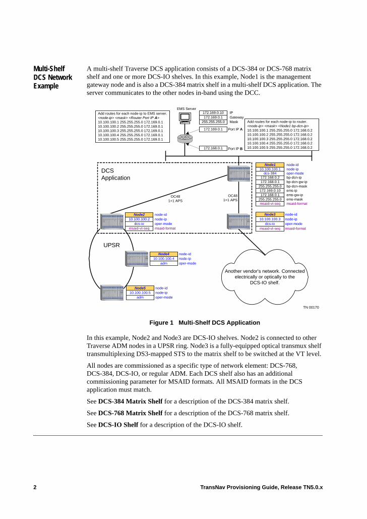
Multi-Shelf DCS Network Example
A multi-shelf Traverse DCS application consists of a DCS-384 or DCS-768 matrix shelf and one or more DCS-IO shelves. In this example, Node1 is the management gateway node and is also a DCS-384 matrix shelf in a multi-shelf DCS application. The server communicates to the other nodes in-band using the DCC.
Figure 1 Multi-Shelf DCS Application
In this example, Node2 and Node3 are DCS-IO shelves. Node2 is connected to other Traverse ADM nodes in a UPSR ring. Node3 is a fully-equipped optical transmux shelf transmultiplexing DS3-mapped STS to the matrix shelf to be switched at the VT level.
All nodes are commissioned as a specific type of network element: DCS-768, DCS-384, DCS-IO, or regular ADM. Each DCS shelf also has an additional commissioning parameter for MSAID formats. All MSAID formats in the DCS application must match.
See DCS-384 Matrix Shelf for a description of the DCS-384 matrix shelf.
See DCS-768 Matrix Shelf for a description of the DCS-768 matrix shelf.
See DCS-IO Shelf for a description of the DCS-IO shelf.
Add routes for each node-ip to router.<node-ip> <mask> <Node1 bp-dcn-ip>10.100.100.1 255.255.255.0 172.168.0.210.100.100.2 255.255.255.0 172.168.0.210.100.100.3 255.255.255.0 172.168.0.210.100.100.4 255.255.255.0 172.168.0.210.100.100.5 255.255.255.0 172.168.0.2
EMS ServerIPGatewayMask
172.169.0.10172.169.0.1
255.255.255.0
Port IP A172.169.0.1
Port IP B172.168.0.1
Add routes for each node-ip to EMS server.<node-ip> <mask> <Router Port IP A>10.100.100.1 255.255.255.0 172.169.0.110.100.100.2 255.255.255.0 172.169.0.110.100.100.3 255.255.255.0 172.169.0.110.100.100.4 255.255.255.0 172.169.0.110.100.100.5 255.255.255.0 172.169.0.1
OC481+1 APS
UPSR
DCSApplication
node-idnode-ip10.100.100.2
dcs-iomsaid-vt-seq
Node2
oper-modemsaid-format
node-ip
ems-ipems-gw-ipems-mask
node-id10.100.100.1
172.169.0.10172.168.0.1
255.255.255.0
Node1
bp-dcn-ipbp-dcn-gw-ipbp-dcn-mask
172.168.0.2172.168.0.1
255.255.255.0
dcs-384
msaid-vt-seq
oper-mode
msaid-format
OC481+1 APS
10.100.100.3dcs-io
msaid-vt-seq
Node3 node-idnode-ipoper-modemsaid-format
Another vendor's network. Connectedelectrically or optically to the
DCS-IO shelf.
10.100.100.4adm
Node4 node-idnode-ipoper-mode
10.100.100.5adm
Node5 node-idnode-ipoper-mode
TN 00170
2 TransNav Provisioning Guide, Release TN5.0.x

DCS-384 Matrix Shelf
A DCS-384 matrix shelf is the node in a Traverse multi-shelf DCS application that performs the VT switching. The DCS-384 matrix shelves provide a non-blocking matrix able to cross-connect and groom 384 STSs worth of VT1.5s.
A Traverse 2000 commissioned as a DCS-384 matrix shelf uses the following configuration:• Slots 1 to 10 contain VT/TU 5G Switch cards• Slots 11 to 18 contain 2-port OC-48 cards (DCS trunks)• Slots 19 and 20 contain redundant shelf controllers
Figure 2 DCS-384 Shelf Configuration
The VT/TU 5G Switch cards groom the incoming and outgoing VT1.5s STSs. The minimum configuration of a DCS-384 matrix shelf requires two VT/TU 5G cards (a working and a protect) and one VT/TU 5G card for each 2-port OC-48 card.
The matrix shelf connects to external shelves (called DCS-IO) with protected OC-48 links. Eight pairs of OC-48 DCS trunks are required to supply 384 STSs of incoming and outgoing VT1.5s supporting up to four DCS-IO shelves..
When you commission a DCS-384 matrix shelf, it is created and preprovisioned with ten VT/TU 5G Switch cards and eight 2-port OC-48 cards. A DCS-384 matrix shelf is also automatically preprovisioned with the following protection groups:• Eight 1+1 APS protection groups for the OC-48 cards• One 1:N equipment protection group for the VT/TU 5G Switch cards
See Chapter 40—“Creating a Multi-Shelf Application” for detailed descriptions of the commissioned hardware configuration, the MSAID assignments, the MSAID allocations and creating a multi-shelf DCS application.
Node1 (DCS-384)
5 G
VT
SW
W
5 G
VT
SW
W
5 G
VT
SW
W
5 G
VT
SW
W
5 G
VT
SW
W
2P
OC48
2P
OC48
5 G
VT
SW
P
5 G
VT
SW
W
5 G
VT
SW
W
5 G
VT
SW
W
5 G
VT
SW
W
1 2 3 4 5 6 7 8 910
11
12
13
14
15
16
17
18
19
20
GCM
GCM
2P
OC48
2P
OC48
2P
OC48
2P
OC48
2P
OC48
2P
OC48
DCS-IO shelves
TransNav Provisioning Guide, Release TN5.0.x 3
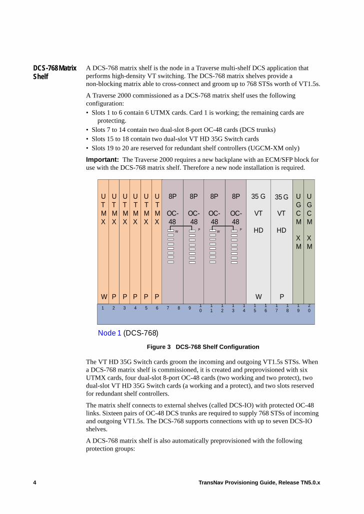
DCS-768 Matrix Shelf
A DCS-768 matrix shelf is the node in a Traverse multi-shelf DCS application that performs high-density VT switching. The DCS-768 matrix shelves provide a non-blocking matrix able to cross-connect and groom up to 768 STSs worth of VT1.5s.
A Traverse 2000 commissioned as a DCS-768 matrix shelf uses the following configuration:• Slots 1 to 6 contain 6 UTMX cards. Card 1 is working; the remaining cards are
protecting.• Slots 7 to 14 contain two dual-slot 8-port OC-48 cards (DCS trunks)• Slots 15 to 18 contain two dual-slot VT HD 35G Switch cards• Slots 19 to 20 are reserved for redundant shelf controllers (UGCM-XM only)
Important: The Traverse 2000 requires a new backplane with an ECM/SFP block for use with the DCS-768 matrix shelf. Therefore a new node installation is required.
Figure 3 DCS-768 Shelf Configuration
The VT HD 35G Switch cards groom the incoming and outgoing VT1.5s STSs. When a DCS-768 matrix shelf is commissioned, it is created and preprovisioned with six UTMX cards, four dual-slot 8-port OC-48 cards (two working and two protect), two dual-slot VT HD 35G Switch cards (a working and a protect), and two slots reserved for redundant shelf controllers.
The matrix shelf connects to external shelves (called DCS-IO) with protected OC-48 links. Sixteen pairs of OC-48 DCS trunks are required to supply 768 STSs of incoming and outgoing VT1.5s. The DCS-768 supports connections with up to seven DCS-IO shelves.
A DCS-768 matrix shelf is also automatically preprovisioned with the following protection groups:
Node 1 (DCS-768)
UTMX
W
35 G
VT
HD
W
1 2 3 4 5 6 7 8 910
11
12
13
14
15
16
17
18
19
20
UGCM
XM
UGCM
XM
UTMX
P
UTMX
P
UTMX
P
UTMX
P
UTMX
P
35 G
VT
HD
P
8P
OC-48
P
8P
OC-48
W
8P
OC-48
P
8P
OC-48
W
4 TransNav Provisioning Guide, Release TN5.0.x
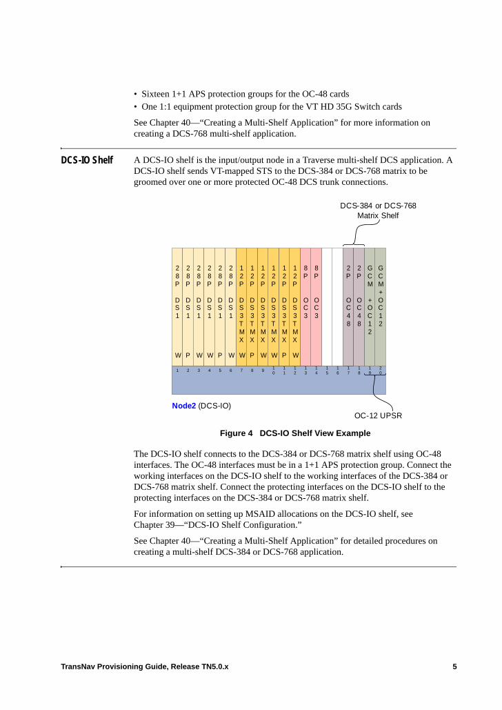
• Sixteen 1+1 APS protection groups for the OC-48 cards• One 1:1 equipment protection group for the VT HD 35G Switch cards
See Chapter 40—“Creating a Multi-Shelf Application” for more information on creating a DCS-768 multi-shelf application.
DCS-IO Shelf A DCS-IO shelf is the input/output node in a Traverse multi-shelf DCS application. A DCS-IO shelf sends VT-mapped STS to the DCS-384 or DCS-768 matrix to be groomed over one or more protected OC-48 DCS trunk connections.
Figure 4 DCS-IO Shelf View Example
The DCS-IO shelf connects to the DCS-384 or DCS-768 matrix shelf using OC-48 interfaces. The OC-48 interfaces must be in a 1+1 APS protection group. Connect the working interfaces on the DCS-IO shelf to the working interfaces of the DCS-384 or DCS-768 matrix shelf. Connect the protecting interfaces on the DCS-IO shelf to the protecting interfaces on the DCS-384 or DCS-768 matrix shelf.
For information on setting up MSAID allocations on the DCS-IO shelf, see Chapter 39—“DCS-IO Shelf Configuration.”
See Chapter 40—“Creating a Multi-Shelf Application” for detailed procedures on creating a multi-shelf DCS-384 or DCS-768 application.
DCS-384 or DCS-768 Matrix Shelf
28 P
DS1
W
28 P
DS1
P
28 P
DS1
W
28 P
DS1
W
28 P
DS1
P
2P
OC48
8P
OC3
8P
OC3
12 P
DS3TMX
W
12 P
DS3TMX
P
12 P
DS3TMX
W
12 P
DS3TMX
W
12 P
DS3TMX
P
12 P
DS3TMX
W
28 P
DS1
W
1 2 3 4 5 6 7 8 910
11
12
13
14
15
16
17
18
19
20
GCM+ OC12
GCM
+ OC12
2P
OC48
Node2 (DCS-IO)OC-12 UPSR
TransNav Provisioning Guide, Release TN5.0.x 5
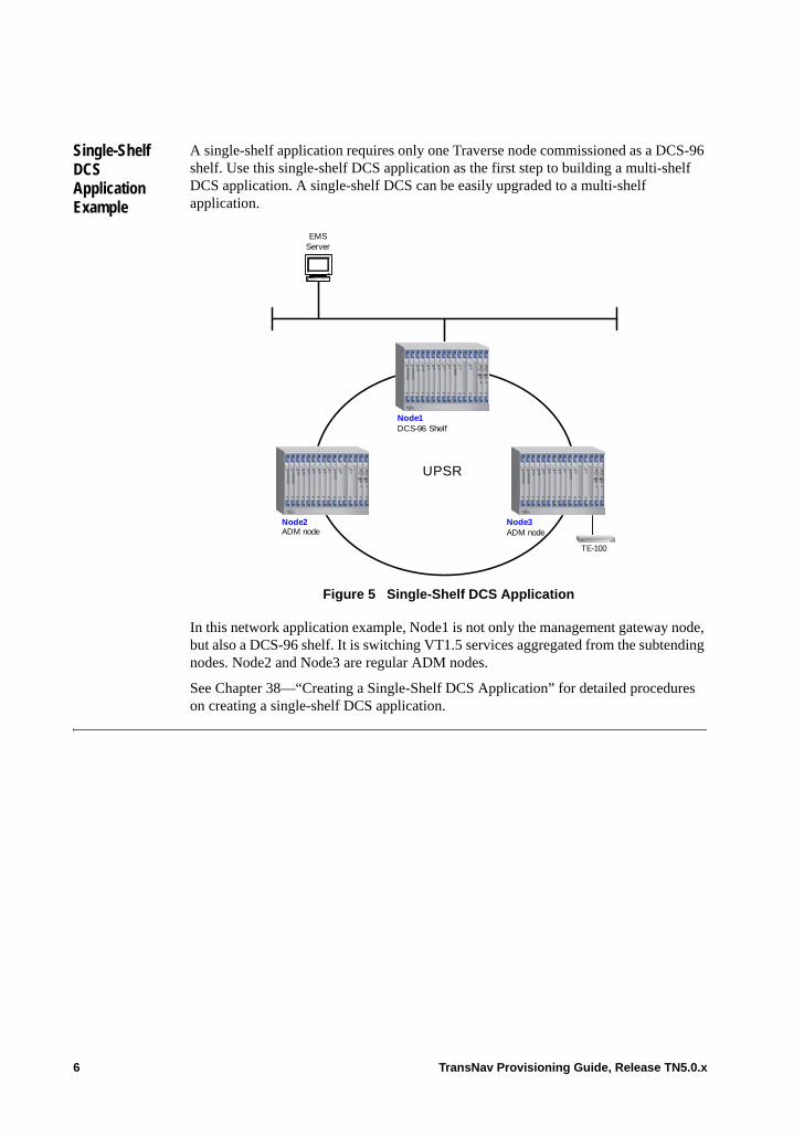
Single-Shelf DCS Application Example
A single-shelf application requires only one Traverse node commissioned as a DCS-96 shelf. Use this single-shelf DCS application as the first step to building a multi-shelf DCS application. A single-shelf DCS can be easily upgraded to a multi-shelf application.
Figure 5 Single-Shelf DCS Application
In this network application example, Node1 is not only the management gateway node, but also a DCS-96 shelf. It is switching VT1.5 services aggregated from the subtending nodes. Node2 and Node3 are regular ADM nodes.
See Chapter 38—“Creating a Single-Shelf DCS Application” for detailed procedures on creating a single-shelf DCS application.
EMS Server
UPSR
Node1DCS-96 Shelf
Node3ADM node
Node2ADM node
TE-100
6 TransNav Provisioning Guide, Release TN5.0.x
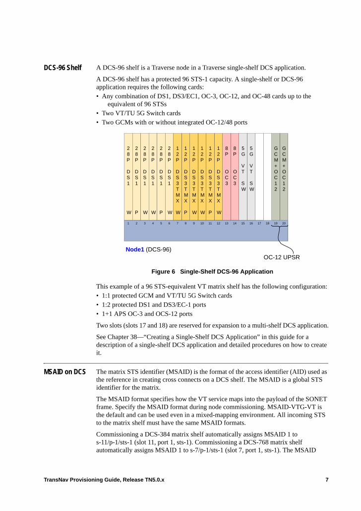
DCS-96 Shelf A DCS-96 shelf is a Traverse node in a Traverse single-shelf DCS application.
A DCS-96 shelf has a protected 96 STS-1 capacity. A single-shelf or DCS-96 application requires the following cards:• Any combination of DS1, DS3/EC1, OC-3, OC-12, and OC-48 cards up to the
equivalent of 96 STSs• Two VT/TU 5G Switch cards• Two GCMs with or without integrated OC-12/48 ports
Figure 6 Single-Shelf DCS-96 Application
This example of a 96 STS-equivalent VT matrix shelf has the following configuration:• 1:1 protected GCM and VT/TU 5G Switch cards• 1:2 protected DS1 and DS3/EC-1 ports• 1+1 APS OC-3 and OCS-12 ports
Two slots (slots 17 and 18) are reserved for expansion to a multi-shelf DCS application.
See Chapter 38—“Creating a Single-Shelf DCS Application” in this guide for a description of a single-shelf DCS application and detailed procedures on how to create it.
MSAID on DCS The matrix STS identifier (MSAID) is the format of the access identifier (AID) used as the reference in creating cross connects on a DCS shelf. The MSAID is a global STS identifier for the matrix.
The MSAID format specifies how the VT service maps into the payload of the SONET frame. Specify the MSAID format during node commissioning. MSAID-VTG-VT is the default and can be used even in a mixed-mapping environment. All incoming STS to the matrix shelf must have the same MSAID formats.
Commissioning a DCS-384 matrix shelf automatically assigns MSAID 1 to s-11/p-1/sts-1 (slot 11, port 1, sts-1). Commissioning a DCS-768 matrix shelf automatically assigns MSAID 1 to s-7/p-1/sts-1 (slot 7, port 1, sts-1). The MSAID
28P
DS1
W
28P
DS1
P
28P
DS1
W
28P
DS1
W
28P
DS1
P
5G
VT
SW
5G
VT
SW
8P
OC3
8P
OC3
12P
DS3TMX
W
12P
DS3TMX
P
12P
DS3TMX
W
12P
DS3TMX
W
12P
DS3TMX
P
12P
DS3TMX
W
28P
DS1
W
1 2 3 4 5 6 7 8 9 10 11 12 13 14 15 16 17 18 19 20
GCM+OC12
GCM+OC12
Node1 (DCS-96)OC-12 UPSR
TransNav Provisioning Guide, Release TN5.0.x 7

numbers increment with each subsequent STS on the port, then move to the next working port and subsequent STS. A user cannot change the assignments on the DCS-384 matrix shelf or DCS-768 matrix shelf.
See Chapter 40—“Creating a Multi-Shelf Application” for detailed descriptions of the MSAID assignments and the MSAID allocations on the DCS-384 matrix shelf or DCS-768 matrix shelf.
MSAID Allocation
On the DCS-IO shelf, a user must allocate an MSAID range to the OC-48 interfaces connected to the DCS-384 shelf or DCS-768 shelf. Because MSAIDs are automatically provisioned on the DCS-384 shelf and DCS-768 shelf, the MSAIDs on the links of the DCS-IO shelf must match the allocation of the corresponding links on the DCS-384 shelf or DCS-768 shelf.
During an upgrade from a DCS-96 shelf to a DCS-IO shelf, MSAID numbers are automatically allocated to slots 17 and 18.
See Chapter 40—“Creating a Multi-Shelf Application,” Allocate MSAID Ranges on DCS-IO Shelf for a detailed procedure.
MSAID Assignments
On the DCS-IO shelf, a user must assign an STS-equivalent to an allocated MSAID. On a DCS-384 matrix shelf and on a DCS-768 matrix shelf, the MSAID are automatically assigned when the shelf is commissioned. Users cannot change the assignments on the DCS-384 matrix shelf or DCS-768 matrix shelf.
See Chapter 40—“Creating a Multi-Shelf Application” for a more information on assigning MSAID numbers on a DCS-384 matrix shelf or DCS-768 matrix shelf.
8 TransNav Provisioning Guide, Release TN5.0.x
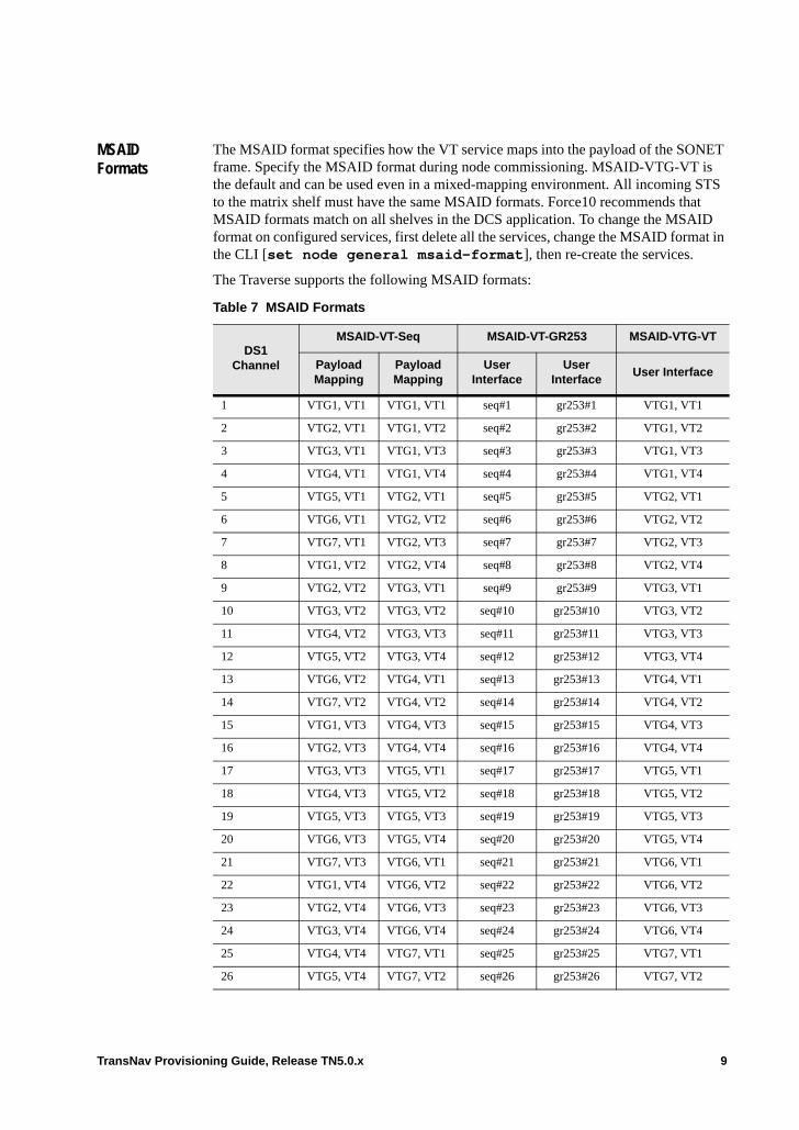
MSAID Formats
The MSAID format specifies how the VT service maps into the payload of the SONET frame. Specify the MSAID format during node commissioning. MSAID-VTG-VT is the default and can be used even in a mixed-mapping environment. All incoming STS to the matrix shelf must have the same MSAID formats. Force10 recommends that MSAID formats match on all shelves in the DCS application. To change the MSAID format on configured services, first delete all the services, change the MSAID format in the CLI [set node general msaid-format], then re-create the services.
The Traverse supports the following MSAID formats:
Table 7 MSAID Formats
DS1 Channel
MSAID-VT-Seq MSAID-VT-GR253 MSAID-VTG-VT
Payload Mapping
Payload Mapping
User Interface
User Interface
User Interface
1 VTG1, VT1 VTG1, VT1 seq#1 gr253#1 VTG1, VT1
2 VTG2, VT1 VTG1, VT2 seq#2 gr253#2 VTG1, VT2
3 VTG3, VT1 VTG1, VT3 seq#3 gr253#3 VTG1, VT3
4 VTG4, VT1 VTG1, VT4 seq#4 gr253#4 VTG1, VT4
5 VTG5, VT1 VTG2, VT1 seq#5 gr253#5 VTG2, VT1
6 VTG6, VT1 VTG2, VT2 seq#6 gr253#6 VTG2, VT2
7 VTG7, VT1 VTG2, VT3 seq#7 gr253#7 VTG2, VT3
8 VTG1, VT2 VTG2, VT4 seq#8 gr253#8 VTG2, VT4
9 VTG2, VT2 VTG3, VT1 seq#9 gr253#9 VTG3, VT1
10 VTG3, VT2 VTG3, VT2 seq#10 gr253#10 VTG3, VT2
11 VTG4, VT2 VTG3, VT3 seq#11 gr253#11 VTG3, VT3
12 VTG5, VT2 VTG3, VT4 seq#12 gr253#12 VTG3, VT4
13 VTG6, VT2 VTG4, VT1 seq#13 gr253#13 VTG4, VT1
14 VTG7, VT2 VTG4, VT2 seq#14 gr253#14 VTG4, VT2
15 VTG1, VT3 VTG4, VT3 seq#15 gr253#15 VTG4, VT3
16 VTG2, VT3 VTG4, VT4 seq#16 gr253#16 VTG4, VT4
17 VTG3, VT3 VTG5, VT1 seq#17 gr253#17 VTG5, VT1
18 VTG4, VT3 VTG5, VT2 seq#18 gr253#18 VTG5, VT2
19 VTG5, VT3 VTG5, VT3 seq#19 gr253#19 VTG5, VT3
20 VTG6, VT3 VTG5, VT4 seq#20 gr253#20 VTG5, VT4
21 VTG7, VT3 VTG6, VT1 seq#21 gr253#21 VTG6, VT1
22 VTG1, VT4 VTG6, VT2 seq#22 gr253#22 VTG6, VT2
23 VTG2, VT4 VTG6, VT3 seq#23 gr253#23 VTG6, VT3
24 VTG3, VT4 VTG6, VT4 seq#24 gr253#24 VTG6, VT4
25 VTG4, VT4 VTG7, VT1 seq#25 gr253#25 VTG7, VT1
26 VTG5, VT4 VTG7, VT2 seq#26 gr253#26 VTG7, VT2
TransNav Provisioning Guide, Release TN5.0.x 9
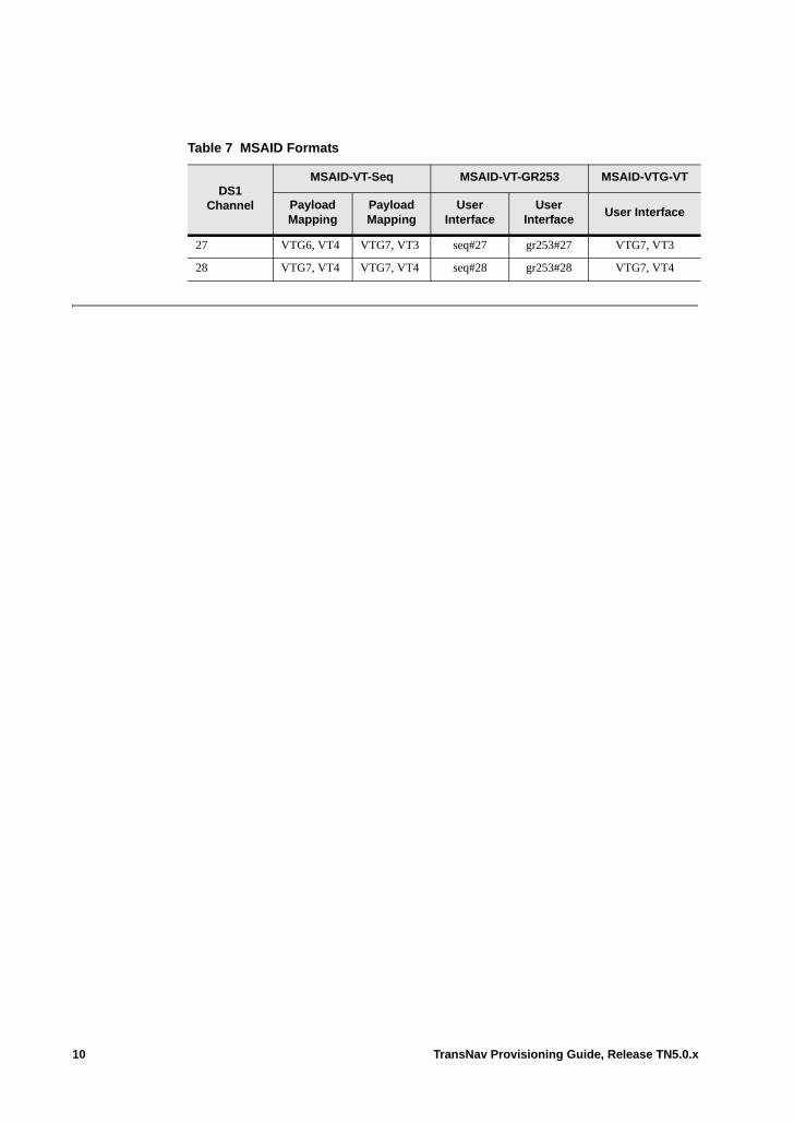
27 VTG6, VT4 VTG7, VT3 seq#27 gr253#27 VTG7, VT3
28 VTG7, VT4 VTG7, VT4 seq#28 gr253#28 VTG7, VT4
Table 7 MSAID Formats
DS1 Channel
MSAID-VT-Seq MSAID-VT-GR253 MSAID-VTG-VT
Payload Mapping
Payload Mapping
User Interface
User Interface
User Interface
10 TransNav Provisioning Guide, Release TN5.0.x
Chapter 38 Creating a Single-Shelf DCS Application
Introductiont This chapter includes the following topics:• Single-Shelf DCS Network Example• Guidelines to Create a DCS-96 Application• Procedure to Create a Single-Shelf DCS Application• Assign MSAID Numbers to STS-Equivalents on DCS-96 Shelf• Create DCS Services on the DCS-96 Shelf• Activate DCS-96 DCS Services• Viewing Transmux Information for DCS MSAID Assignments
TransNav Provisioning Guide, Release TN5.0.x 1
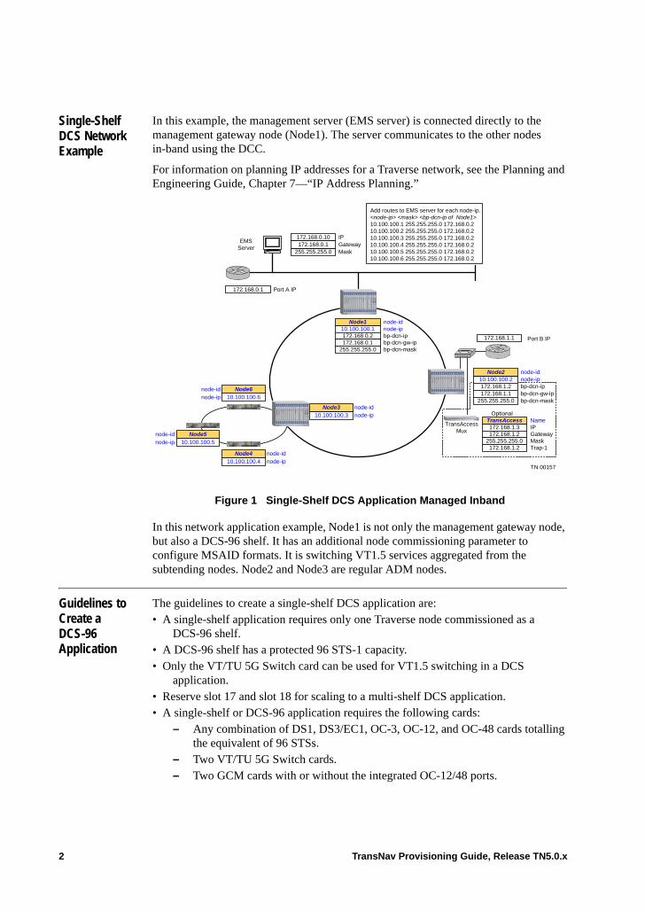
Single-Shelf DCS Network Example
In this example, the management server (EMS server) is connected directly to the management gateway node (Node1). The server communicates to the other nodes in-band using the DCC.
For information on planning IP addresses for a Traverse network, see the Planning and Engineering Guide, Chapter 7—“IP Address Planning.”
Figure 1 Single-Shelf DCS Application Managed Inband
In this network application example, Node1 is not only the management gateway node, but also a DCS-96 shelf. It has an additional node commissioning parameter to configure MSAID formats. It is switching VT1.5 services aggregated from the subtending nodes. Node2 and Node3 are regular ADM nodes.
Guidelines to Create a DCS-96 Application
The guidelines to create a single-shelf DCS application are: • A single-shelf application requires only one Traverse node commissioned as a
DCS-96 shelf. • A DCS-96 shelf has a protected 96 STS-1 capacity.• Only the VT/TU 5G Switch card can be used for VT1.5 switching in a DCS
application. • Reserve slot 17 and slot 18 for scaling to a multi-shelf DCS application.• A single-shelf or DCS-96 application requires the following cards:
– Any combination of DS1, DS3/EC1, OC-3, OC-12, and OC-48 cards totalling the equivalent of 96 STSs.
– Two VT/TU 5G Switch cards.– Two GCM cards with or without the integrated OC-12/48 ports.
Port A IP
node-ipbp-dcn-ipbp-dcn-gw-ipbp-dcn-mask
node-id
IP
MaskTrap-1
NameTransAccess
Mux Gateway
Optional
10.100.100.1Node1
172.168.1.3172.168.1.2
255.255.255.0172.168.1.2
TransAccess
Add routes to EMS server for each node-ip.<node-ip> <mask> <bp-dcn-ip of Node1>10.100.100.1 255.255.255.0 172.168.0.210.100.100.2 255.255.255.0 172.168.0.210.100.100.3 255.255.255.0 172.168.0.210.100.100.4 255.255.255.0 172.168.0.210.100.100.5 255.255.255.0 172.168.0.210.100.100.6 255.255.255.0 172.168.0.2
EMSServer
172.168.0.1
172.168.1.1
IPGatewayMask
172.168.0.10
255.255.255.0172.168.0.1
Port B IP172.168.0.2172.168.0.1
255.255.255.0
node-ip
node-id
10.100.100.5
Node5
node-ipnode-id
10.100.100.4Node4
node-id
bp-dcn-ipbp-dcn-gw-ipbp-dcn-mask
node-ip10.100.100.2172.168.1.2172.168.1.1
Node2
255.255.255.0
10.100.100.3Node3
node-ipnode-id
node-ipnode-id
10.100.100.6Node6
TN 00157
2 TransNav Provisioning Guide, Release TN5.0.x
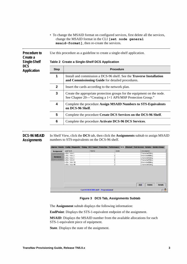
• To change the MSAID format on configured services, first delete all the services, change the MSAID format in the CLI [set node general msaid-format], then re-create the services.
Procedure to Create a Single-Shelf DCS Application
Use this procedure as a guideline to create a single-shelf application.
DCS-96 MSAID Assignments
In Shelf View, click the DCS tab, then click the Assignments subtab to assign MSAID numbers to STS-equivalents on the DCS-96 shelf.
Figure 3 DCS Tab, Assignments Subtab
The Assignment subtab displays the following information:
EndPoint: Displays the STS-1-equivalent endpoint of the assignment.
MSAID: Displays the MSAID number from the available allocations for each STS-1-equivalent piece of equipment.
State. Displays the state of the assignment.
Table 2 Create a Single-Shelf DCS Application
Step Procedure
1 Install and commission a DCS-96 shelf. See the Traverse Installation and Commissioning Guide for detailed procedures.
2 Insert the cards according to the network plan.
3 Create the appropriate protection groups for the equipment on the node. See Chapter 20—“Creating a 1+1 APS/MSP Protection Group.”
4 Complete the procedure Assign MSAID Numbers to STS-Equivalents on DCS-96 Shelf.
5 Complete the procedure Create DCS Services on the DCS-96 Shelf.
6 Complete the procedure Activate DCS-96 DCS Services.
TransNav Provisioning Guide, Release TN5.0.x 3

Description: Displays a user-defined alphanumeric character string to describe the MSAID assignments in the DCS application.
Command buttons are as follows:
Add: Click to assign MSAID numbers to STS-equivalents on the DCS-96 shelf. The Assignment Details dialog box displays. See DCS Assignment Details, page 4.
Delete: Select an assignment in the list, then click Delete to remove the assignment from the user interface.
Details: Displays the Assignment Details dialog box. See DCS Assignment Details, page 4.
DCS Assignment Details
In Shelf View, click the DCS tab to display the Assignment subtab, then click Add to add MSAID assignments to this DCS-96 shelf. The Assignment Details dialog box displays.
Figure 4 Assignment Details Dialog Box
This dialog box displays the following information:
EndPoint: Click the field to display the Choose an Endpoint dialog box. Navigate the tree and select the STS-1-equivalent endpoint of the assignment.
MSAID: Select one MSAID number from the available allocations for each STS-1-equivalent piece of equipment.
Description: Enter an alphanumeric character string to describe the MSAID assignments in the DCS application. Do not use any other punctuation or special characters.
Command buttons are as follows:
Show TxRx Path: Click Show TxRx Path to display the Path Display for Service screen. See the Operations and Maintenance Guide, Chapter 9—“Managing Service Paths”for information on this screen.
Apply: Click to save your changes and return to the Assignment subtab on the main screen.
Cancel: Click to cancel any changes and return to the Assignment subtab on the main screen.
4 TransNav Provisioning Guide, Release TN5.0.x
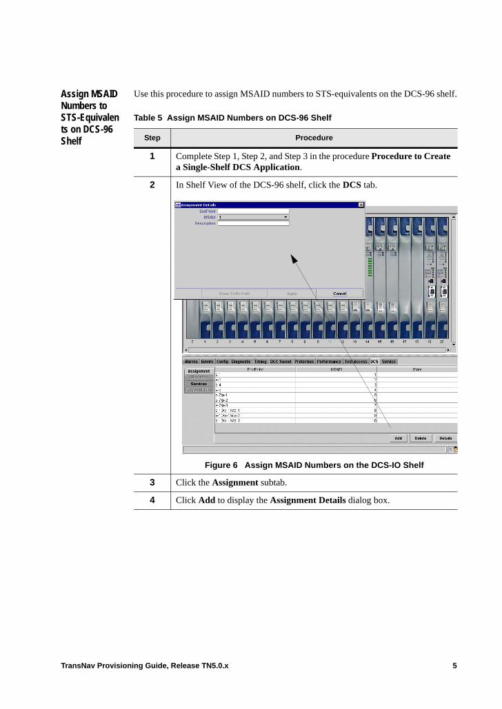
Assign MSAID Numbers to STS-Equivalents on DCS-96 Shelf
Use this procedure to assign MSAID numbers to STS-equivalents on the DCS-96 shelf.
Table 5 Assign MSAID Numbers on DCS-96 Shelf
Step Procedure
1 Complete Step 1, Step 2, and Step 3 in the procedure Procedure to Create a Single-Shelf DCS Application.
2 In Shelf View of the DCS-96 shelf, click the DCS tab.
Figure 6 Assign MSAID Numbers on the DCS-IO Shelf
3 Click the Assignment subtab.
4 Click Add to display the Assignment Details dialog box.
TransNav Provisioning Guide, Release TN5.0.x 5
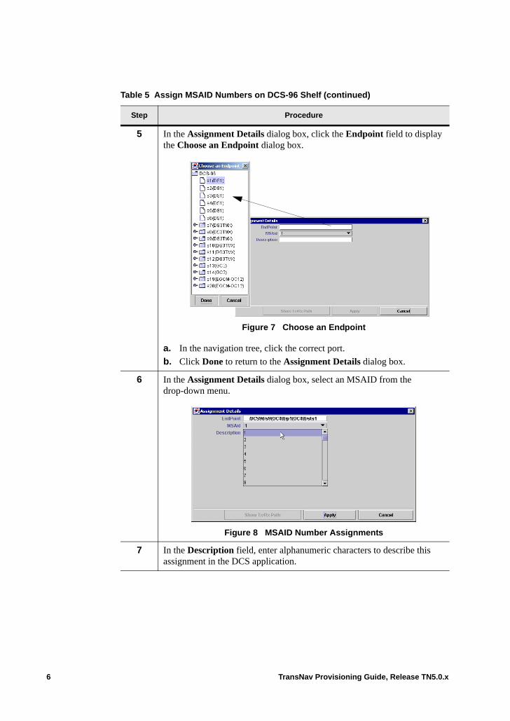
5 In the Assignment Details dialog box, click the Endpoint field to display the Choose an Endpoint dialog box.
Figure 7 Choose an Endpoint
a. In the navigation tree, click the correct port.
b. Click Done to return to the Assignment Details dialog box.
6 In the Assignment Details dialog box, select an MSAID from the drop-down menu.
Figure 8 MSAID Number Assignments
7 In the Description field, enter alphanumeric characters to describe this assignment in the DCS application.
Table 5 Assign MSAID Numbers on DCS-96 Shelf (continued)
Step Procedure
6 TransNav Provisioning Guide, Release TN5.0.x
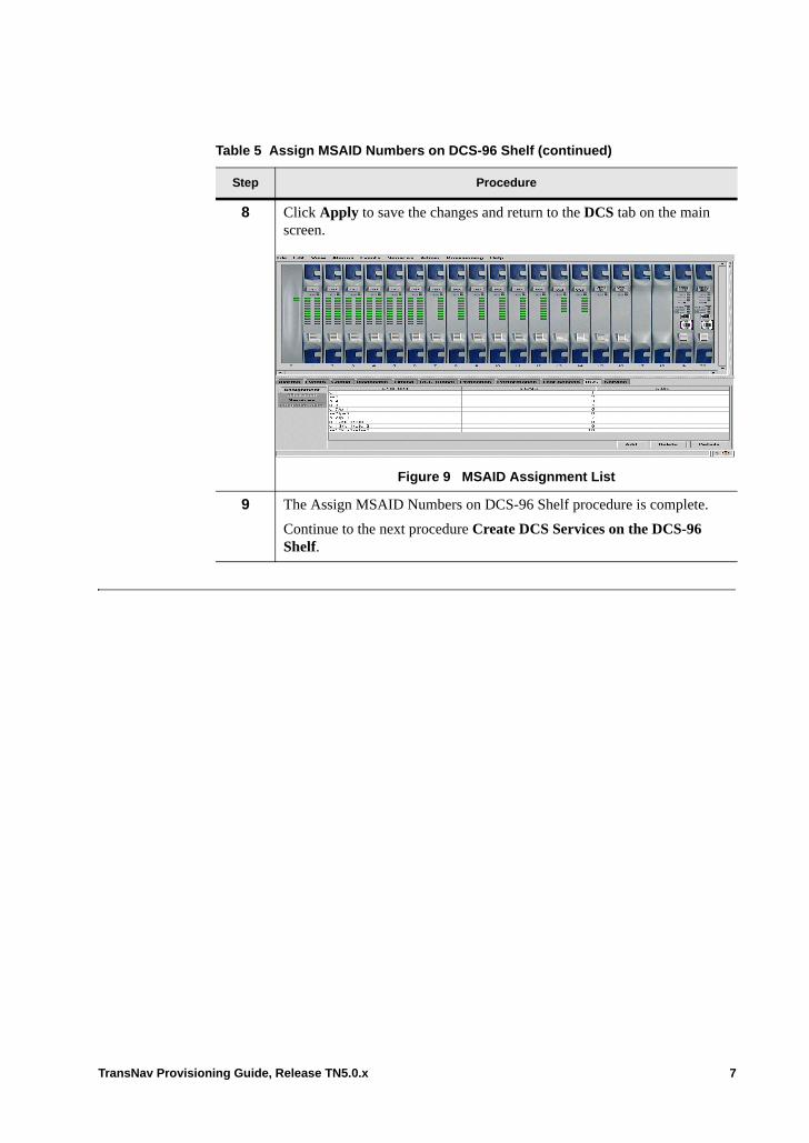
8 Click Apply to save the changes and return to the DCS tab on the main screen.
Figure 9 MSAID Assignment List
9 The Assign MSAID Numbers on DCS-96 Shelf procedure is complete.
Continue to the next procedure Create DCS Services on the DCS-96 Shelf.
Table 5 Assign MSAID Numbers on DCS-96 Shelf (continued)
Step Procedure
TransNav Provisioning Guide, Release TN5.0.x 7
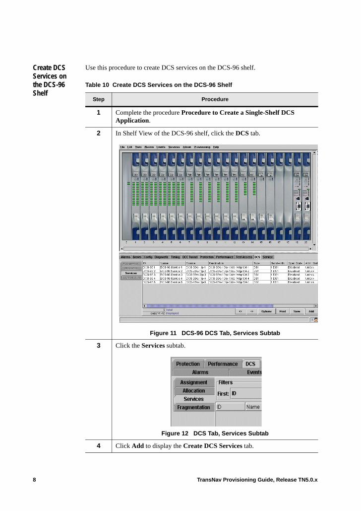
Create DCS Services on the DCS-96 Shelf
Use this procedure to create DCS services on the DCS-96 shelf.
Table 10 Create DCS Services on the DCS-96 Shelf
Step Procedure
1 Complete the procedure Procedure to Create a Single-Shelf DCS Application.
2 In Shelf View of the DCS-96 shelf, click the DCS tab.
Figure 11 DCS-96 DCS Tab, Services Subtab
3 Click the Services subtab.
Figure 12 DCS Tab, Services Subtab
4 Click Add to display the Create DCS Services tab.
8 TransNav Provisioning Guide, Release TN5.0.x
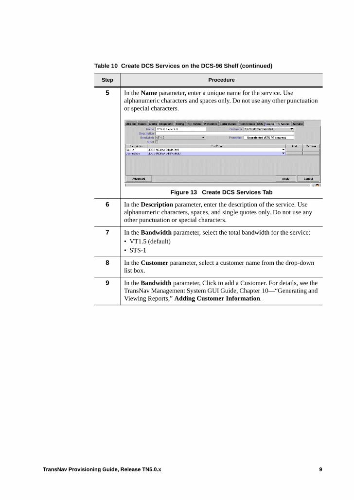
5 In the Name parameter, enter a unique name for the service. Use alphanumeric characters and spaces only. Do not use any other punctuation or special characters.
Figure 13 Create DCS Services Tab
6 In the Description parameter, enter the description of the service. Use alphanumeric characters, spaces, and single quotes only. Do not use any other punctuation or special characters.
7 In the Bandwidth parameter, select the total bandwidth for the service: • VT1.5 (default)• STS-1
8 In the Customer parameter, select a customer name from the drop-down list box.
9 In the Bandwidth parameter, Click to add a Customer. For details, see the TransNav Management System GUI Guide, Chapter 10—“Generating and Viewing Reports,” Adding Customer Information.
Table 10 Create DCS Services on the DCS-96 Shelf (continued)
Step Procedure
TransNav Provisioning Guide, Release TN5.0.x 9
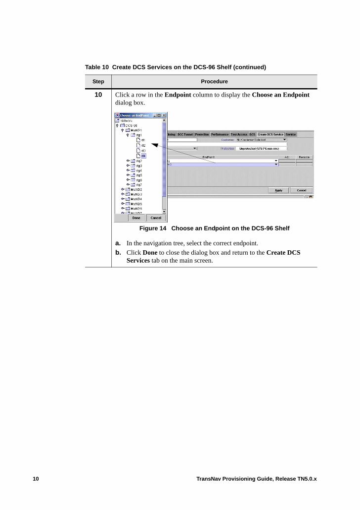
10 Click a row in the Endpoint column to display the Choose an Endpoint dialog box.
Figure 14 Choose an Endpoint on the DCS-96 Shelf
a. In the navigation tree, select the correct endpoint.
b. Click Done to close the dialog box and return to the Create DCS Services tab on the main screen.
Table 10 Create DCS Services on the DCS-96 Shelf (continued)
Step Procedure
10 TransNav Provisioning Guide, Release TN5.0.x

11 Configure the protection attributes for this service. Click the Protection field to display the Protection dialog box.
Figure 15 Protection Dialog Box
In the Protection Type parameter, select one of the following options: • Unprotected (default): Used for services that are either unprotected, 1+1
APS/MSP protected, protected with an equipment protection group, or a 1+1 Path Protection group.
• Any: The system finds the best effort of protection through the network. There may be some spans of unprotected links, but the system will create the service.
• Full: The system only create the service if there is full protection on every transport link in the network.
• 1+1 Path Protected: If this service is protected by another service (two services model).
• UPSR Ingress: If the service is a SONET-VT service and is creating a bidirectional path across two interconnected UPSRs.
12 For services that have a protection type configured, configure the following parameters.• Revertive (default is not selected): Select the check box to switch traffic
back to the original path once the failure condition no longer exists.• WTR Time (default is 5): Specifies the amount of time (in minutes) for
the system to wait before restoring traffic to the original path once the failure condition no longer exists. Specify a value between 1 and 60 minutes.
If this service is protected by a BLSR or an MS-SP ring, go to Step 13.
If this service is protected by another service (two services path protection model), go to Step 14.
Table 10 Create DCS Services on the DCS-96 Shelf (continued)
Step Procedure
TransNav Provisioning Guide, Release TN5.0.x 11
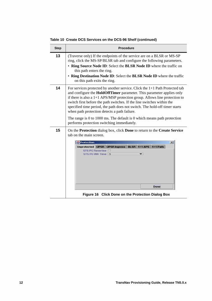
13 (Traverse only) If the endpoints of the service are on a BLSR or MS-SP ring, click the MS-SP/BLSR tab and configure the following parameters. • Ring Source Node ID: Select the BLSR Node ID where the traffic on
this path enters the ring.• Ring Destination Node ID: Select the BLSR Node ID where the traffic
on this path exits the ring.
14 For services protected by another service. Click the 1+1 Path Protected tab and configure the HoldOffTimer parameter. This parameter applies only if there is also a 1+1 APS/MSP protection group. Allows line protection to switch first before the path switches. If the line switches within the specified time period, the path does not switch. The hold-off timer starts when path protection detects a path failure.
The range is 0 to 1000 ms. The default is 0 which means path protection performs protection switching immediately.
15 On the Protection dialog box, click Done to return to the Create Service tab on the main screen.
Figure 16 Click Done on the Protection Dialog Box
Table 10 Create DCS Services on the DCS-96 Shelf (continued)
Step Procedure
12 TransNav Provisioning Guide, Release TN5.0.x
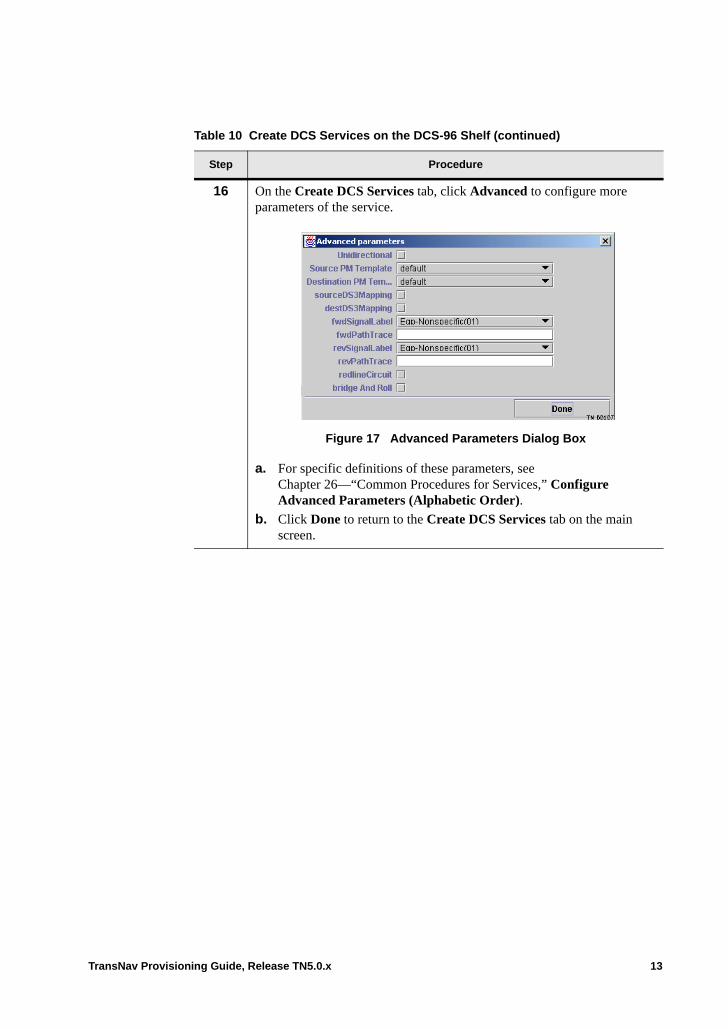
16 On the Create DCS Services tab, click Advanced to configure more parameters of the service.
Figure 17 Advanced Parameters Dialog Box
a. For specific definitions of these parameters, see Chapter 26—“Common Procedures for Services,” Configure Advanced Parameters (Alphabetic Order).
b. Click Done to return to the Create DCS Services tab on the main screen.
Table 10 Create DCS Services on the DCS-96 Shelf (continued)
Step Procedure
TransNav Provisioning Guide, Release TN5.0.x 13
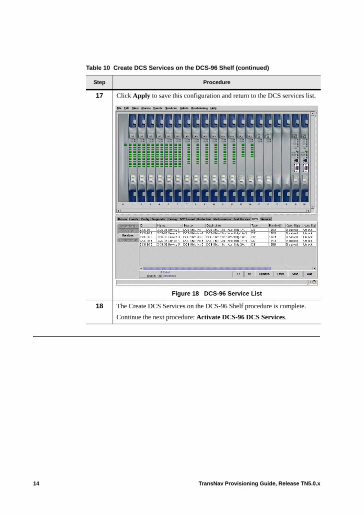
17 Click Apply to save this configuration and return to the DCS services list.
Figure 18 DCS-96 Service List
18 The Create DCS Services on the DCS-96 Shelf procedure is complete.
Continue the next procedure: Activate DCS-96 DCS Services.
Table 10 Create DCS Services on the DCS-96 Shelf (continued)
Step Procedure
14 TransNav Provisioning Guide, Release TN5.0.x

Activate DCS-96 DCS Services
Use this procedure to activate DCS services on the DCS-96 shelf.
Table 19 Activate DCS Services on a DCS-96 Shelf
Step Procedure
1 Complete the procedure: Create DCS Services on the DCS-96 Shelf.
2 In Shelf View of the DCS-96 shelf, click the DCS tab.
Figure 20 DCS-96 DCS Tab, Services Subtab
3 Click the Services subtab.
4 Press the Shift key and select all the provisioned DCS services.
5 Right-click on the service list and select Activate from the menu.
6 The Activate DCS Services on a DCS-96 Shelf procedure is complete.
TransNav Provisioning Guide, Release TN5.0.x 15
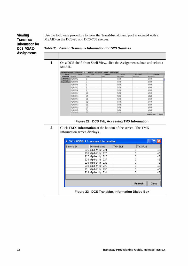
Viewing Transmux Information for DCS MSAID Assignments
Use the following procedure to view the TransMux slot and port associated with a MSAID on the DCS-96 and DCS-768 shelves.
Table 21 Viewing Transmux Information for DCS Services
1 On a DCS shelf, from Shelf View, click the Assignment subtab and select a MSAID.
Figure 22 DCS Tab, Accessing TMX Information
2 Click TMX Information at the bottom of the screen. The TMX Information screen displays.
Figure 23 DCS TransMux Information Dialog Box
16 TransNav Provisioning Guide, Release TN5.0.x
3 View the following information:
Service ID: The service ID assigned by the system.
Service Name: Indicates the name of the selected service.
TMX Slot: Indicates the slot number of the card associated with the MSAID.
TMX Port: Indicates the port number on the card associated with the MSAID.
4 Click Refresh to update the data to see any changes or click Close to return to the previous screen.
Table 21 Viewing Transmux Information for DCS Services
TransNav Provisioning Guide, Release TN5.0.x 17

18 TransNav Provisioning Guide, Release TN5.0.x

Chapter 39 DCS-IO Shelf Configuration
Introduction A DCS-IO shelf is the input/output shelf in a Traverse multi-shelf DCS application. A Traverse multi-shelf consists of a DCS-384 matrix shelf or DCS-768 matrix shelf and one or more DCS-IO shelves. This chapter explains the configuration of a DCS-IO shelf.
This chapter explains the following topics for DCS-IO shelf:• DCS-IO MSAID Allocation• DCS-IO MSAID Assignments• DCS-IO Assignment Details
For a description of a DCS-IO shelf, see Chapter 37—“DCS Application Overview,” DCS-IO Shelf.
TransNav Provisioning Guide, Release TN5.0.x 1

DCS-IO MSAID Allocation
It is important to understand how the MSAIDs are allocated in the DCS-384 matrix shelf or DCS-768 matrix shelf before you allocate MSAIDs on the DCS-IO shelf. See Chapter 40—“Creating a Multi-Shelf Application” for a detailed description of MSAID allocation on the DCS-384 matrix shelf or DCS-768 matrix shelf.
On the DCS-IO shelf, allocate the correct range of MSAIDs to the ports (links) connected to the DCS-384 matrix shelf or DCS-768 matrix shelf. If the port is in a 1+1 APS protection group, allocate the range to the working port
For example, connect the OC-48 interfaces in slots 17 and 18 on the DCS-IO shelf to slots 13 and 14 on a DCS-384 matrix shelf. Allocate the 97 to 144 MSAID range on the DCS-IO shelf to slot 17. Allocate the 145 to 192 MSAID range on the DCS-IO shelf to slot 18.
Port: Click a row in the Port column to display the Choose a Port dialog box. Select working port. Click Done to close the dialog box and return to the DCS tab on the main window.
The port column displays the port using the following syntax:
/NodeId/slot <cardType>/port <PortType> (a | p)
where:NodeId is the user-defined name of the nodeslot is the number of the slot in which the card is insertedport is the number of the port on the cardPortType is the speed of the SONET interfacea (active) represents the traffic on that port is receiving traffic from the working trafficp (protecting) represents that there is a protection switch and the port is receiving traffic from the protecting link. This option is invalid.
MSAID Range: Select the correct MSAID range. The MSAID range for the port needs to match the MSAID allocation range on the far end of the link (on the DCS-384 matrix shelf or DCS-768 matrix shelf). See Chapter 40—“Creating a Multi-Shelf Application”for a detailed description of MSAID ranges on the DCS-384 matrix shelf or DCS-768 matrix shelf.
2 TransNav Provisioning Guide, Release TN5.0.x

Select one of the following options:• Unset MSAID range. Removes the row from the table.• [ 1 - 48 ] to assign MSAIDs 1 to 48 to this OC-48 interface.• [ 49 - 96 ] to assign MSAIDs 49 to 96 to this OC-48 interface.• [ 97 - 144 ] to assign MSAIDs 97 to 144 to this OC-48 interface.• [ 145 - 192 ] to assign MSAIDs 145 to 192 to this OC-48 interface.• [ 193 - 240 ] to assign MSAIDs 193 to 240 to this OC-48 interface.• [ 241 - 288 ] to assign MSAIDs 241 to 288 to this OC-48 interface.• [ 289 - 336 ] to assign MSAIDs 289 to 336 to this OC-48 interface.• [ 337 - 384 ] to assign MSAIDs 337 to 384 to this OC-48 interface.
For the DCS-768 matrix shelf, the following additional MSAID options are available:• [ 385 - 432 ] to assign MSAIDs 385 to 432 to this OC-48 interface.• [ 433 - 480 ] to assign MSAIDs 433 to 480 to this OC-48 interface.• [ 481 - 528 ] to assign MSAIDs 481 to 528 to this OC-48 interface.• [ 529 - 576 ] to assign MSAIDs 529 to 576 to this OC-48 interface.• [ 577 - 624 ] to assign MSAIDs 577 to 624 to this OC-48 interface.• [ 625 - 672 ] to assign MSAIDs 625 to 672 to this OC-48 interface.• [ 673 - 720 ] to assign MSAIDs 673 to 720 to this OC-48 interface.• [ 721 - 768 ] to assign MSAIDs 721 to 768 to this OC-48 interface.
Command buttons are as follows:
Apply: Click to save the MSAID allocation.
Cancel: Click to cancel provisioning.
DCS-IO MSAID Assignments
In Shelf View for a DCS-IO shelf, click the DCS tab, then click the Assignment subtab.
Figure 1 DCS-IO MSAID Assignments
EndPoint: Displays the STS-1 equivalent endpoint. The endpoint can be one of the following STS-1 equivalents:• DS1 card• DS3CC port
TransNav Provisioning Guide, Release TN5.0.x 3
• DS3TMX port• EC1 port• OC-N port, STS number
MSAID: For a DCS-384 matrix shelf, this is a number between 1 and 384 depending on the MSAID allocation on the DCS-IO shelf. For a DCS-768S matrix shelf, this is a number between 1 and 768, depending on the MSAID allocation on the DCS-IO shelf. See DCS-IO MSAID Allocation.
State: Displays the status of the assignment.
Description. Displays a user-defined alphanumeric character string to describe the assignments in the DCS application.
Command buttons are as follows:
(De)Activate: Allows or stops the selected assignments from carrying traffic. This button is context-sensitive. If the selected assignment is NOT activated, clicking the button will activate the assignment. If the selected assignment IS activated, clicking the button will stop the assignment from carrying traffic.
Either hold the Ctrl key and click individual assignments OR hold the Shift key and select a range of assignments.
Roll: Transfer traffic from one facility to another without interrupting service. Create all of the bridge services individually first, then roll and commit multiple services. See the Chapter 32—“Bridging and Rolling Services” for detailed procedures on bridging and rolling services.
Unroll: An undo command.
Commit Rolled: After you roll traffic to a new facility, commit the transfer and delete the original service.
Add: Add an assignment to the assignment list. See DCS-IO Assignment Details.
Delete: Click to remove the selected assignments from the list.
Details: Click to see the exact source and the configured parameters of the selected assignment.
Last Error: Click an assignment, then click this button to see the last error on the assignment.
4 TransNav Provisioning Guide, Release TN5.0.x
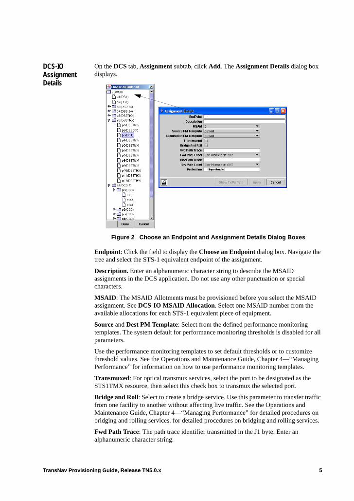
DCS-IO Assignment Details
On the DCS tab, Assignment subtab, click Add. The Assignment Details dialog box displays.
Figure 2 Choose an Endpoint and Assignment Details Dialog Boxes
Endpoint: Click the field to display the Choose an Endpoint dialog box. Navigate the tree and select the STS-1 equivalent endpoint of the assignment.
Description. Enter an alphanumeric character string to describe the MSAID assignments in the DCS application. Do not use any other punctuation or special characters.
MSAID: The MSAID Allotments must be provisioned before you select the MSAID assignment. See DCS-IO MSAID Allocation. Select one MSAID number from the available allocations for each STS-1 equivalent piece of equipment.
Source and Dest PM Template: Select from the defined performance monitoring templates. The system default for performance monitoring thresholds is disabled for all parameters.
Use the performance monitoring templates to set default thresholds or to customize threshold values. See the Operations and Maintenance Guide, Chapter 4—“Managing Performance” for information on how to use performance monitoring templates.
Transmuxed: For optical transmux services, select the port to be designated as the STS1TMX resource, then select this check box to transmux the selected port.
Bridge and Roll: Select to create a bridge service. Use this parameter to transfer traffic from one facility to another without affecting live traffic. See the Operations and Maintenance Guide, Chapter 4—“Managing Performance” for detailed procedures on bridging and rolling services. for detailed procedures on bridging and rolling services.
Fwd Path Trace: The path trace identifier transmitted in the J1 byte. Enter an alphanumeric character string.
TransNav Provisioning Guide, Release TN5.0.x 5

Fwd Path Label: The path signal label (C2 byte in the STS path overhead) in the forward direction of the LSP. Select one of the following options:• Unequipped(00)• Eqp-Nonspecific(01) (default): Equipped - Nonspecific Payload• VT-Structured(02): VT-structured STS-1 SPE• Locked VT(03): Locked virtual tributary (VT) mode• DS3 Async(04): Asynchronous mapping for E3 or DS3 (Planned for future release.)• DS4NA Async(12): Asynchronous mapping for DS4NA or E4 (Planned for future
release.)• ATM Map(13): Mapping for ATM• DQDB Map(14): Mapping for DQDB• FDDI Async(15): Asynchronous mapping for FDDI• HDLC-SONET(16): HDLC-Over-SONET mapping• X.86 (18)• GFP (1B)• POS No-Scramble (CF)• Test Signal (FE): O.181 Test Signal (TSS1 to TSS3) mapping
Rev Path Trace: The expected path trace identifier transmitted in the J1 byte. Enter an alphanumeric character string. Not used for unidirectional connections.
Rev Path Label: The path signal label (C2 byte in the STS path overhead) in the reverse direction of the LSP. Not used for unidirectional connections. Select one of the following options:• Unequipped(00)• Eqp-Nonspecific(01) (default): Equipped - Nonspecific Payload• VT-Structured(02): VT-structured STS-1 SPE• Locked VT(03): Locked virtual tributary (VT) mode• DS3 Async(04): Asynchronous mapping for DS3• DS4NA Async(12): Asynchronous mapping for DS4NA• ATM Map(13): Mapping for ATM• DQDB Map(14): Mapping for DQDB• FDDI Async(15): Asynchronous mapping for FDDI• HDLC-PPP(16): HDLC-Over-SONET mapping• X.86(18)• GFP (1B)• POS No-Scramble (CF)• Test Signal (FE): O.181 Test Signal (TSS1 to TSS3) mapping
Protection. The only valid protection for an MSAID Allocation on a DCS-IO shelf is Unprotected (default).
6 TransNav Provisioning Guide, Release TN5.0.x
Chapter 40 Creating a Multi-Shelf Application
Introduction A Traverse multi-shelf DCS application consists of a DCS-384 or DCS-768 matrix shelf and a DCS-IO shelf.
A DCS-384 matrix shelf supports from one to four DCS-IO shelves and can switch up to 384 STSs.
A DCS-768 matrix shelf is a higher density matrix shelf that supports from one to seven DCS-IO shelves. Used in conjunction with dual-slot 8-port OC48, VT-HD 40G and UGCM-XM cards, the DCS-768 matrix shelf provides increased capacity to switch up to 768 STSs.
Note: The DCS-768 requires a new 6G mesh-type Traverse 2000 shelf.
This chapter includes the following topics:• Multi-Shelf DCS Network Example• Shelf Views of a Multi-Shelf DCS Application
– DCS-384 Matrix Shelf Applications– DCS-768 Matrix Shelf Applications
• Guidelines to Create a Multi-Shelf DCS Application• Protection Groups on DCS-384 and DCS-768 Matrix Shelves• Procedure to Create a Multi-Shelf DCS Application• DCS-384 and DCS-768 Multi-Shelf MSAID Assignments
– DCS-384 and DCS-768 MSAID Allocation• Allocate MSAID Ranges on DCS-IO Shelf• Assign MSAID Number to STS- Equivalents on DCS-IO Shelf• Activate MSAID Assignments on DCS-IO Shelf• Create DCS Services on the DCS-384 or DCS-768 Matrix Shelf• Activate DCS-384 or DCS-768 Services• DCS-384 Fragmentation
Create the DCS-384 or DCS-768 matrix shelf when you commission the node. See the Traverse Hardware Installation and Commissioning Guide, Chapter 13—“Traverse Node Start-up and Commissioning” for node commissioning procedures.
Important: The DCS-768 matrix shelf must be installed as a new node. Upgrade of the hardware from a DCS-96 or DCS-384 matrix shelf is not supported.
TransNav Provisioning Guide, Release TN5.0.x 1
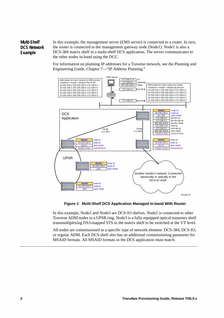
Multi-Shelf DCS Network Example
In this example, the management server (EMS server) is connected to a router. In turn, the router is connected to the management gateway node (Node1). Node1 is also a DCS-384 matrix shelf in a multi-shelf DCS application. The server communicates to the other nodes in-band using the DCC.
For information on planning IP addresses for a Traverse network, see the Planning and Engineering Guide, Chapter 7—“IP Address Planning.”
Figure 1 Multi-Shelf DCS Application Managed In-band With Router
In this example, Node2 and Node3 are DCS-IO shelves. Node2 is connected to other Traverse ADM nodes in a UPSR ring. Node3 is a fully-equipped optical transmux shelf transmultiplexing DS3-mapped STS to the matrix shelf to be switched at the VT level.
All nodes are commissioned as a specific type of network element: DCS-384, DCS-IO, or regular ADM. Each DCS shelf also has an additional commissioning parameter for MSAID formats. All MSAID formats in the DCS application must match.
Add routes for each node-ip to router.<node-ip> <mask> <Node1 bp-dcn-ip>10.100.100.1 255.255.255.0 172.168.0.210.100.100.2 255.255.255.0 172.168.0.210.100.100.3 255.255.255.0 172.168.0.210.100.100.4 255.255.255.0 172.168.0.210.100.100.5 255.255.255.0 172.168.0.2
EMS ServerIPGatewayMask
172.169.0.10172.169.0.1
255.255.255.0
Port IP A172.169.0.1
Port IP B172.168.0.1
Add routes for each node-ip to EMS server.<node-ip> <mask> <Router Port IP A>10.100.100.1 255.255.255.0 172.169.0.110.100.100.2 255.255.255.0 172.169.0.110.100.100.3 255.255.255.0 172.169.0.110.100.100.4 255.255.255.0 172.169.0.110.100.100.5 255.255.255.0 172.169.0.1
OC481+1 APS
UPSR
DCSApplication
node-idnode-ip10.100.100.2
dcs-iomsaid-vt-seq
Node2
oper-modemsaid-format
node-ip
ems-ipems-gw-ipems-mask
node-id10.100.100.1
172.169.0.10172.168.0.1
255.255.255.0
Node1
bp-dcn-ipbp-dcn-gw-ipbp-dcn-mask
172.168.0.2172.168.0.1
255.255.255.0
dcs-384
msaid-vt-seq
oper-mode
msaid-format
OC481+1 APS
10.100.100.3dcs-io
msaid-vt-seq
Node3 node-idnode-ipoper-modemsaid-format
Another vendor's network. Connectedelectrically or optically to the
DCS-IO shelf.
10.100.100.4adm
Node4 node-idnode-ipoper-mode
10.100.100.5adm
Node5 node-idnode-ipoper-mode
TN 00170
2 TransNav Provisioning Guide, Release TN5.0.x
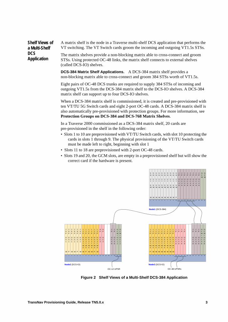
Shelf Views of a Multi-Shelf DCS Application
A matrix shelf is the node in a Traverse multi-shelf DCS application that performs the VT switching. The VT Switch cards groom the incoming and outgoing VT1.5s STSs.
The matrix shelves provide a non-blocking matrix able to cross-connect and groom STSs. Using protected OC-48 links, the matrix shelf connects to external shelves (called DCS-IO) shelves.
DCS-384 Matrix Shelf Applications. A DCS-384 matrix shelf provides a non-blocking matrix able to cross-connect and groom 384 STSs worth of VT1.5s.
Eight pairs of OC-48 DCS trunks are required to supply 384 STSs of incoming and outgoing VT1.5s from the DCS-384 matrix shelf to the DCS-IO shelves. A DCS-384 matrix shelf can support up to four DCS-IO shelves.
When a DCS-384 matrix shelf is commissioned, it is created and pre-provisioned with ten VT/TU 5G Switch cards and eight 2-port OC-48 cards. A DCS-384 matrix shelf is also automatically pre-provisioned with protection groups. For more information, see Protection Groups on DCS-384 and DCS-768 Matrix Shelves.
In a Traverse 2000 commissioned as a DCS-384 matrix shelf, 20 cards are pre-provisioned in the shelf in the following order:• Slots 1 to 10 are preprovisioned with VT/TU Switch cards, with slot 10 protecting the
cards in slots 1 through 9. The physical provisioning of the VT/TU Switch cards must be made left to right, beginning with slot 1
• Slots 11 to 18 are preprovisioned with 2-port OC-48 cards.• Slots 19 and 20, the GCM slots, are empty in a preprovisioned shelf but will show the
correct card if the hardware is present.
Figure 2 Shelf Views of a Multi-Shelf DCS-384 Application
Node1 (DCS-384)
5G
VT
SW
W
5G
VT
SW
W
5G
VT
SW
W
5G
VT
SW
W
5G
VT
SW
W
2P
OC48
2P
OC48
5G
VT
SW
P
5G
VT
SW
W
5G
VT
SW
W
5G
VT
SW
W
5G
VT
SW
W
1 2 3 4 5 6 7 8 9 10 11 12 13 14 15 16 17 18 19 20
GCM
GCM
2P
OC48
2P
OC48
2P
OC48
2P
OC48
2P
OC48
2P
OC48
28P
DS1
W
28P
DS1
P
28P
DS1
W
28P
DS1
W
28P
DS1
P
2P
OC48
8P
OC3
8P
OC3
12P
DS3TMX
W
12P
DS3TMX
P
12P
DS3TMX
W
12P
DS3TMX
W
12P
DS3TMX
P
12P
DS3TMX
W
28P
DS1
W
1 2 3 4 5 6 7 8 9 10 11 12 13 14 15 16 17 18 19 20
GCM+OC12
GCM+OC12
2P
OC48
Node2 (DCS-IO)
12P
DS3TMX
P
12P
DS3TMX
W
12P
DS3TMX
W
12P
DS3TMX
W
12P
DS3TMX
W
1P
OC48
1P
OC48
1P
OC48
1P
OC48
12P
DS3TMX
W
12P
DS3TMX
W
12P
DS3TMX
W
12P
DS3TMX
W
1 2 3 4 5 6 7 8 9 10 11 12 13 14 15 16 17 18 19 20
GCM+OC48
GCM+OC48
2P
OC48
2P
OC48
2P
OC48
Node3 (DCS-IO)
OC-12 UPSR OC-48 UPSRs
TransNav Provisioning Guide, Release TN5.0.x 3
Figure 2 shows a DCS-384 node connected to two DCS-IO shelves. Node2 is a DCS-IO shelf that was upgraded from a DCS-96 shelf. Slots 15 and 16 contained two VT/TU 5G Switch cards that were redeployed to the DCS-384 matrix shelf after the upgrade.
Node3 is a transmux node that is optically transmultiplexing 96 DS3-mapped STSs then switching VT-mapped STSs to the DCS-384 matrix shelf. The OC-48 interfaces in slot 18 are protected by the OC-48 interfaces on the GCM cards.
DCS-768 Matrix Shelf Applications. The DCS-768 matrix shelf performs higher-density VT switching and is able to cross-connect and groom the incoming and outgoing 768 STSs worth of VT1.5s. Sixteen pairs of OC-48 DCS trunks are required to supply 768 STSs of incoming and outgoing VT1.5s to a full complement of seven DCS-IO shelves. The DCS-768 matrix shelf contains only optical inputs; there are no electrical inputs.
Note: With this release, a new node installation is required to install a DCS-768 matrix shelf application. Upgrades from a DCS-96 or DCS-384 shelf are not supported.
In a Traverse 2000 commissioned as a DCS-768 matrix shelf, 18 cards are pre-provisioned in the shelf in the following order:• Slots 1 through 6 are pre-provisioned with UTMX cards. The card in slot 1 is the
protect card, the cards in slots 2 through 6 are the working cards.• Slots 7 through 14 are pre-provisioned with dual-slot 8-port OC-48 cards. The ports
on the cards in slots 7 / 8 and 11 / 12 are the working ports; the ports on the cards in slots 9 / 10 and 13 / 14 are the protecting ports.
• Slots 15 through 18 are pre-provisioned with dual-slot VT-HD 40G Switch cards, with the card in slots 17 / 18 being the working card and the card in slots 15 / 16 being the protecting card. Physical provisioning of the VT-HD 40G Switch cards must be made left to right.
• Slots 19 and 20, the GCM slots, are empty in a pre-provisioned shelf but will show the correct card (UGCM-XM) if the hardware is present.
The DCS-768 matrix shelf is also automatically pre-provisioned with the following protection groups:• Sixteen 1+1 APS protection groups for the dual-slot 8-port OC-48 cards• One 1:N equipment protection group for the VT-HD 40G Switch cards
Note: Unique to the DCS-768 matrix shelf is that cards are locked by default when a service is created and must be manually unlocked. Each DCS-768 matrix shelf can support 1344 bi-directional unlocked services or 2688 uni-directional unlocked services.
4 TransNav Provisioning Guide, Release TN5.0.x
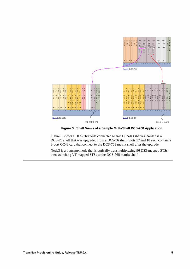
Figure 3 Shelf Views of a Sample Multi-Shelf DCS-768 Application
Figure 3 shows a DCS-768 node connected to two DCS-IO shelves. Node2 is a DCS-IO shelf that was upgraded from a DCS-96 shelf. Slots 17 and 18 each contain a 2-port OC48 card that connect to the DCS-768 matrix shelf after the upgrade.
Node3 is a transmux node that is optically transmultiplexing 96 DS3-mapped STSs then switching VT-mapped STSs to the DCS-768 matrix shelf.
Node1 (DCS-768)
12 P
DS3TMX
P
12 P
DS3TMX
W
12 P
DS3TMX
W
12 P
DS3TMX
W
12 P
DS3TMX
W
12 P
DS3TMX
W
12 P
DS3TMX
W
12 P
DS3TMX
W
12 P
DS3TMX
W
1 2 3 4 5 6 7 8 9 10 11 12 13 14 15 16 17 18 19 20
GCM+OC48
GCM
+OC48
2P
OC48
P
2P
OC48
W
2P
OC48
Node3 (DCS-IO)
2P
OC48
2P
OC48
2P
OC48
2P
OC48
2P
OC48
2P
OC48
UTMX
W
40 G
VT
HD
W
1 2 3 4 5 6 7 8 9 10 11 12 13 14 15 16 17 18 19 20
UGCM
XM
UGCM
XM
UTMX
P
UTMX
P
UTMX
P
UTMX
P
UTMX
P
40 G
VT
HD
P
8P
OC-48
8P
OC-48
8P
OC-48
8P
OC-48
W P
28 P
DS1
W
28 P
DS1
P
28 P
DS1
W
28 P
DS1
W
28 P
DS1
P
2P
OC48
W
8P
OC3
8P
OC3
12 P
DS3TMX
W
12 P
DS3TMX
P
12 P
DS3TMX
W
12 P
DS3TMX
W
12 P
DS3TMX
P
12 P
DS3TMX
W
28 P
DS1
W
1 2 3 4 5 6 7 8 9 10 11 12 13 14 15 16 17 18 19
GCM+ OC12
GCM
+ OC12
Node2 (DCS-IO)
2P
OC48
P
OC-48 1+1 APS
W P
W P
OC-48 1+1 APS
20
TransNav Provisioning Guide, Release TN5.0.x 5
Guidelines to Create a Multi-Shelf DCS Application
The guidelines to create a multi-shelf DCS application are: • A multi-shelf DCS application requires at least two Traverse nodes: a DCS-384 or
DCS-768 matrix shelf and a DCS-IO shelf.• A commissioned DCS-384 or DCS-768 matrix shelf has all eighteen slots
pre-provisioned.
Note: With this release, a new installation is required to install a DCS-768 matrix shelf application. Upgrades from a DCS-96 or DCS-384 are not supported.
DCS-384 matrix shelf minimum hardware configuration. The minimum hardware configuration to deploy a DCS-384 matrix shelf is:– Three VT/TU 5G Switch cards: two working (slot 1 and slot 2) and one protect
(slot 10)
Note: The physical provisioning of the VT/TU Switch cards must be made left to right, beginning with slot 1. Two 2-port OC-48 cards inserted in slots 11 and 12 (in a 1+1 APS protection group)
– Two GCM cards• Expanding the minimum hardware configuration, the DCS-384 matrix shelf requires
one VT/TU 5G Switch card for each working OC-48 interface..
DCS-768 matrix shelf minimum hardware configuration. The minimum hardware configuration to deploy a DCS-768 matrix shelf is:– Two UTMX cards: One working (slot 1) and one protecting (slots 2 through 6)– Two dual-slot 8-port OC-48 cards inserted in slots 7/8 and 9/10. The ports on
the cards in slots 7/8 are working; the ports on the cards in slots 9/10 are protecting.
– Two dual-slot VT-HD 40G Switch cards: one working (slots 15 and 16) and one protect (slots 17 and 18)
– Two UGCM-XM cards
Note: The physical provisioning of the VT/TU and VT-HD Switch cards must be made left to right, beginning with slot 1.
Note: Lock out the slots that are non-equipped to allow the protection group to protect the equipped cards.
Important: If the physical configuration of your DCS-384 has empty VT/TU Switch card slots, then provision a protection group Lockout on these pre-provisioned and unpopulated cards from the VT Protection Equipment tab.
6 TransNav Provisioning Guide, Release TN5.0.x
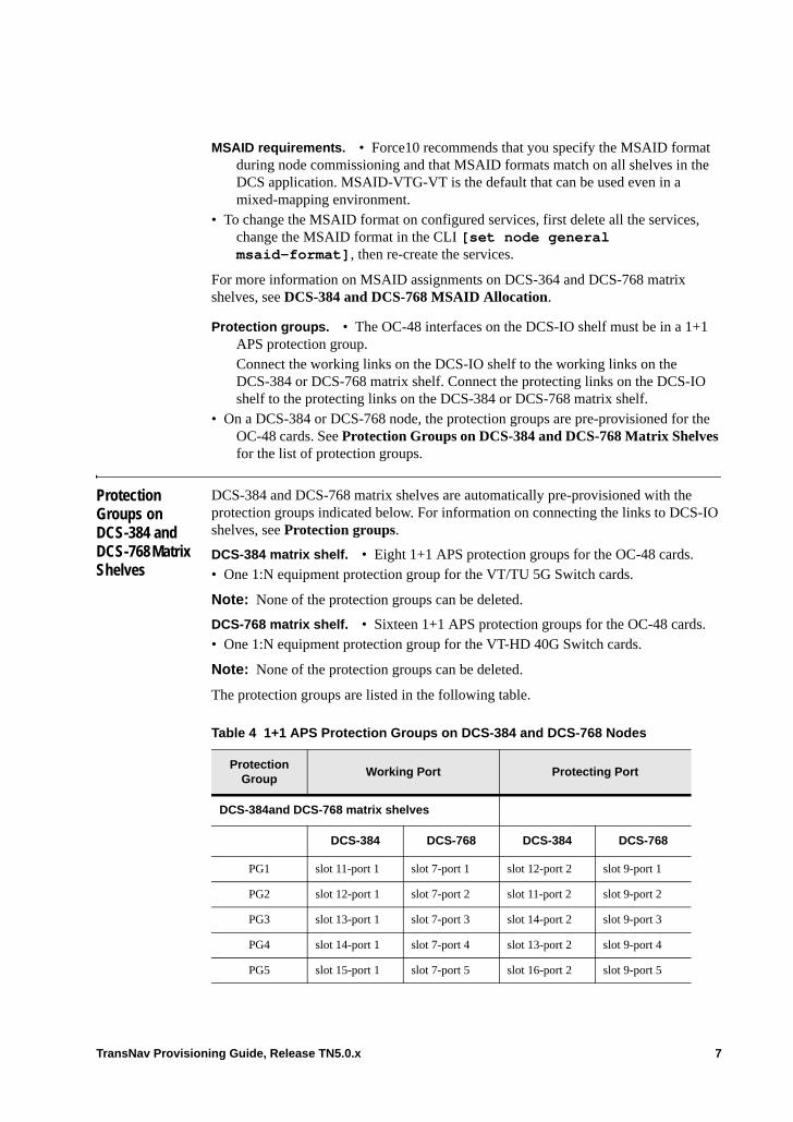
MSAID requirements. • Force10 recommends that you specify the MSAID format during node commissioning and that MSAID formats match on all shelves in the DCS application. MSAID-VTG-VT is the default that can be used even in a mixed-mapping environment.
• To change the MSAID format on configured services, first delete all the services, change the MSAID format in the CLI [set node general msaid-format], then re-create the services.
For more information on MSAID assignments on DCS-364 and DCS-768 matrix shelves, see DCS-384 and DCS-768 MSAID Allocation.
Protection groups. • The OC-48 interfaces on the DCS-IO shelf must be in a 1+1 APS protection group.Connect the working links on the DCS-IO shelf to the working links on the DCS-384 or DCS-768 matrix shelf. Connect the protecting links on the DCS-IO shelf to the protecting links on the DCS-384 or DCS-768 matrix shelf.
• On a DCS-384 or DCS-768 node, the protection groups are pre-provisioned for the OC-48 cards. See Protection Groups on DCS-384 and DCS-768 Matrix Shelves for the list of protection groups.
Protection Groups on DCS-384 and DCS-768 Matrix Shelves
DCS-384 and DCS-768 matrix shelves are automatically pre-provisioned with the protection groups indicated below. For information on connecting the links to DCS-IO shelves, see Protection groups.
DCS-384 matrix shelf. • Eight 1+1 APS protection groups for the OC-48 cards.• One 1:N equipment protection group for the VT/TU 5G Switch cards.
Note: None of the protection groups can be deleted.
DCS-768 matrix shelf. • Sixteen 1+1 APS protection groups for the OC-48 cards.• One 1:N equipment protection group for the VT-HD 40G Switch cards.
Note: None of the protection groups can be deleted.
The protection groups are listed in the following table.
Table 4 1+1 APS Protection Groups on DCS-384 and DCS-768 Nodes
Protection Group
Working Port Protecting Port
DCS-384and DCS-768 matrix shelves
DCS-384 DCS-768 DCS-384 DCS-768
PG1 slot 11-port 1 slot 7-port 1 slot 12-port 2 slot 9-port 1
PG2 slot 12-port 1 slot 7-port 2 slot 11-port 2 slot 9-port 2
PG3 slot 13-port 1 slot 7-port 3 slot 14-port 2 slot 9-port 3
PG4 slot 14-port 1 slot 7-port 4 slot 13-port 2 slot 9-port 4
PG5 slot 15-port 1 slot 7-port 5 slot 16-port 2 slot 9-port 5
TransNav Provisioning Guide, Release TN5.0.x 7
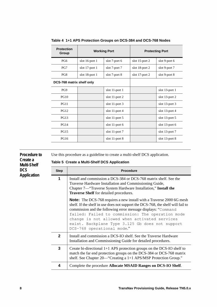
Procedure to Create a Multi-Shelf DCS Application
Use this procedure as a guideline to create a multi-shelf DCS application.
PG6 slot 16-port 1 slot 7-port 6 slot 15-port 2 slot 9-port 6
PG7 slot 17-port 1 slot 7-port 7 slot 18-port 2 slot 9-port 7
PG8 slot 18-port 1 slot 7-port 8 slot 17-port 2 slot 9-port 8
DCS-768 matrix shelf only
PG9 slot 11-port 1 slot 13-port 1
PG10 slot 11-port 2 slot 13-port 2
PG11 slot 11-port 3 slot 13-port 3
PG12 slot 11-port 4 slot 13-port 4
PG13 slot 11-port 5 slot 13-port 5
PG14 slot 11-port 6 slot 13-port 6
PG15 slot 11-port 7 slot 13-port 7
PG16 slot 11-port 8 slot 13-port 8
Table 4 1+1 APS Protection Groups on DCS-384 and DCS-768 Nodes
Protection Group
Working Port Protecting Port
Table 5 Create a Multi-Shelf DCS Application
Step Procedure
1 Install and commission a DCS-384 or DCS-768 matrix shelf. See the Traverse Hardware Installation and Commissioning Guide, Chapter 7—“Traverse System Hardware Installation,” Install the Traverse Shelf for detailed procedures.
Note: The DCS-768 requires a new install with a Traverse 2000 6G mesh shelf. If the shelf in use does not support the DCS-768, the shelf will fail to commission and the following error message displays: “Command failed: Failed to commission: The operation mode change is not allowed when activated services exist. Backplane Type 3.125 Gb does not support DCS-768 operational mode.”
2 Install and commission a DCS-IO shelf. See the Traverse Hardware Installation and Commissioning Guide for detailed procedures.
3 Create bi-directional 1+1 APS protection groups on the DCS-IO shelf to match the far end protection groups on the DCS-384 or DCS-768 matrix shelf. See Chapter 20—“Creating a 1+1 APS/MSP Protection Group.”
4 Complete the procedure Allocate MSAID Ranges on DCS-IO Shelf.
8 TransNav Provisioning Guide, Release TN5.0.x
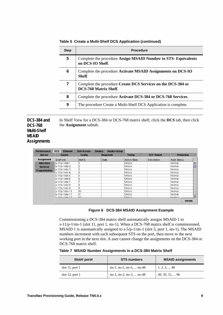
DCS-384 and DCS-768 Multi-Shelf MSAID Assignments
In Shelf View for a DCS-384 or DCS-768 matrix shelf, click the DCS tab, then click the Assignment subtab.
Figure 6 DCS-384 MSAID Assignment Example
Commissioning a DCS-384 matrix shelf automatically assigns MSAID 1 to s-11/p-1/sts-1 (slot 11, port 1, sts-1). When a DCS-768 matrix shelf is commissioned, MSAID 1 is automatically assigned to s-5/p-1/sts-1 (slot 5, port 1, sts-1). The MSAID numbers increment with each subsequent STS on the port, then move to the next working port in the next slot. A user cannot change the assignments on the DCS-384 or DCS-768 matrix shelf.
5 Complete the procedure Assign MSAID Number to STS- Equivalents on DCS-IO Shelf.
6 Complete the procedure Activate MSAID Assignments on DCS-IO Shelf.
7 Complete the procedure Create DCS Services on the DCS-384 or DCS-768 Matrix Shelf.
8 Complete the procedure Activate DCS-384 or DCS-768 Services.
9 The procedure Create a Multi-Shelf DCS Application is complete.
Table 5 Create a Multi-Shelf DCS Application (continued)
Step Procedure
Table 7 MSAID Number Assignments in a DCS-384 Matrix Shelf
Slot#/ port# STS numbers MSAID assignments
slot 11, port 1 sts-1, sts-2, sts-3, ... sts-48 1, 2, 3, ... 48
slot 12, port 1 sts-1, sts-2, sts-3, ... sts-48 49, 50, 51, ... 96
TransNav Provisioning Guide, Release TN5.0.x 9
Command buttons are as follows:
Details: Select an endpoint on the Assignment subtab screen and click Details to display the Assignment Details dialog box.
slot 13, port 1 sts-1, sts-2, sts-3, ... sts-48 97, 98, 99, ... 144
slot 14, port 1 sts-1, sts-2, sts-3, ... sts-48 145, 146, 147, ... 192
slot 15, port 1 sts-1, sts-2, sts-3, ... sts-48 193, 194, 195, ... 240
slot 16, port 1 sts-1, sts-2, sts-3, ... sts-48 241, 242, 243, ... 288
slot 17, port 1 sts-1, sts-2, sts-3, ... sts-48 289, 290, 291, ... 336
slot 18, port 1 sts-1, sts-2, sts-3, ... sts-48 337, 338, 339, ... 384
Table 8 MSAID Number Assignments in a DCS-768 Matrix Shelf
Slot#/ port# STS numbers MSAID assignments
slot 7, port 1 sts-1, sts-2, sts-3, ... sts-48 1, 2, 3, ... 48
slot 7, port 2 sts-1, sts-2, sts-3, ... sts-48 49, 50, 51, ... 96
slot 7, port 3 sts-1, sts-2, sts-3, ... sts-48 97, 98, 99, ... 144
slot 7, port 4 sts-1, sts-2, sts-3, ... sts-48 145, 146, 147, ... 192
slot 7, port 5 sts-1, sts-2, sts-3, ... sts-48 193, 194, 195, ... 240
slot 7, port 6 sts-1, sts-2, sts-3, ... sts-48 241, 242, 243, ... 288
slot 7, port 7 sts-1, sts-2, sts-3, ... sts-48 289, 290, 291, ... 336
slot 7, port 8 sts-1, sts-2, sts-3, ... sts-48 337, 338, 339, ... 384
slot 11, port 1 sts-1, sts-2, sts-3, ... sts-48 385, 386, 387, ... 432
slot 11, port 2 sts-1, sts-2, sts-3, ... sts-48 433, 434, 435, ... 480
slot 11, port 3 sts-1, sts-2, sts-3, ... sts-48 481, 482, 483, ... 528
slot 11, port 4 sts-1, sts-2, sts-3, ... sts-48 529, 530, 531, ... 576
slot 11, port 5 sts-1, sts-2, sts-3, ... sts-48 577, 578, 579, ... 624
slot 11, port 6 sts-1, sts-2, sts-3, ... sts-48 625, 626, 627, ... 672
slot 11, port 7 sts-1, sts-2, sts-3, ... sts-48 673, 674, 675, ...720
slot 11, port 8 sts-1, sts-2, sts-3, ... sts-48 721, 722, 723, ... 768
Table 7 MSAID Number Assignments in a DCS-384 Matrix Shelf
Slot#/ port# STS numbers MSAID assignments
10 TransNav Provisioning Guide, Release TN5.0.x
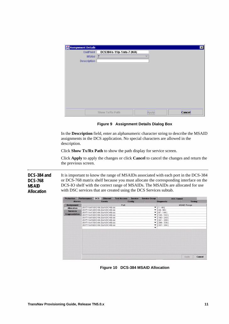
Figure 9 Assignment Details Dialog Box
In the Description field, enter an alphanumeric character string to describe the MSAID assignments in the DCS application. No special characters are allowed in the description.
Click Show Tx/Rx Path to show the path display for service screen.
Click Apply to apply the changes or click Cancel to cancel the changes and return the the previous screen.
DCS-384 and DCS-768 MSAID Allocation
It is important to know the range of MSAIDs associated with each port in the DCS-384 or DCS-768 matrix shelf because you must allocate the corresponding interface on the DCS-IO shelf with the correct range of MSAIDs. The MSAIDs are allocated for use with DSC services that are created using the DCS Services subtab.
Figure 10 DCS-384 MSAID Allocation
TransNav Provisioning Guide, Release TN5.0.x 11
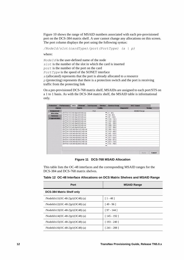
Figure 10 shows the range of MSAID numbers associated with each pre-provisioned port on the DCS-384 matrix shelf. A user cannot change any allocations on this screen. The port column displays the port using the following syntax:
/NodeId/slot(cardType)/port(PortType) (a | p)
where:
NodeId is the user-defined name of the nodeslot is the number of the slot in which the card is insertedport is the number of the port on the cardPortType is the speed of the SONET interfacea (allocated) represents that the port is already allocated to a resourcep (protecting) represents that there is a protection switch and the port is receiving traffic from the protecting link
On a pre-provisioned DCS-768 matrix shelf, MSAIDs are assigned to each port/STS on a 1 to 1 basis. As with the DCS-364 matrix shelf, the MSAID table is informational only.
Figure 11 DCS-768 MSAID Allocation
This table lists the OC-48 interfaces and the corresponding MSAID ranges for the DCS-384 and DCS-768 matrix shelves.
Table 12 OC-48 Interface Allocations on DCS Matrix Shelves and MSAID Range
Port MSAID Range
DCS-384 Matrix Shelf only
/NodeId/s11(OC-48-2)p1(OC48) (a) [ 1 - 48 ]
/NodeId/s12(OC-48-2)p1(OC48) (a) [ 49 - 96 ]
/NodeId/s13(OC-48-2)p1(OC48) (a) [ 97 - 144 ]
/NodeId/s14(OC-48-2)p1(OC48) (a) [ 145 - 192 ]
/NodeId/s15(OC-48-2)p1(OC48) (a) [ 193 - 240 ]
/NodeId/s16(OC-48-2)p1(OC48) (a) [ 241 - 288 ]
12 TransNav Provisioning Guide, Release TN5.0.x
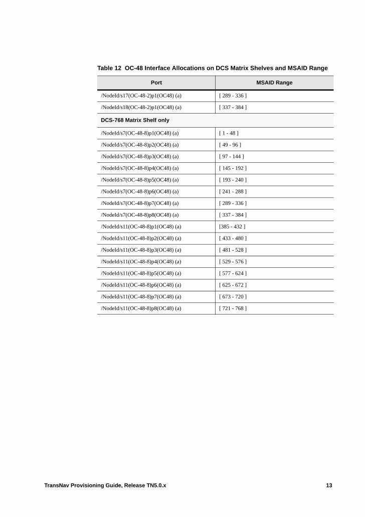
/NodeId/s17(OC-48-2)p1(OC48) (a) [ 289 - 336 ]
/NodeId/s18(OC-48-2)p1(OC48) (a) [ 337 - 384 ]
DCS-768 Matrix Shelf only
/NodeId/s7(OC-48-8)p1(OC48) (a) [ 1 - 48 ]
/NodeId/s7(OC-48-8)p2(OC48) (a) [ 49 - 96 ]
/NodeId/s7(OC-48-8)p3(OC48) (a) [ 97 - 144 ]
/NodeId/s7(OC-48-8)p4(OC48) (a) [ 145 - 192 ]
/NodeId/s7(OC-48-8)p5(OC48) (a) [ 193 - 240 ]
/NodeId/s7(OC-48-8)p6(OC48) (a) [ 241 - 288 ]
/NodeId/s7(OC-48-8)p7(OC48) (a) [ 289 - 336 ]
/NodeId/s7(OC-48-8)p8(OC48) (a) [ 337 - 384 ]
/NodeId/s11(OC-48-8)p1(OC48) (a) [385 - 432 ]
/NodeId/s11(OC-48-8)p2(OC48) (a) [ 433 - 480 ]
/NodeId/s11(OC-48-8)p3(OC48) (a) [ 481 - 528 ]
/NodeId/s11(OC-48-8)p4(OC48) (a) [ 529 - 576 ]
/NodeId/s11(OC-48-8)p5(OC48) (a) [ 577 - 624 ]
/NodeId/s11(OC-48-8)p6(OC48) (a) [ 625 - 672 ]
/NodeId/s11(OC-48-8)p7(OC48) (a) [ 673 - 720 ]
/NodeId/s11(OC-48-8)p8(OC48) (a) [ 721 - 768 ]
Table 12 OC-48 Interface Allocations on DCS Matrix Shelves and MSAID Range
Port MSAID Range
TransNav Provisioning Guide, Release TN5.0.x 13
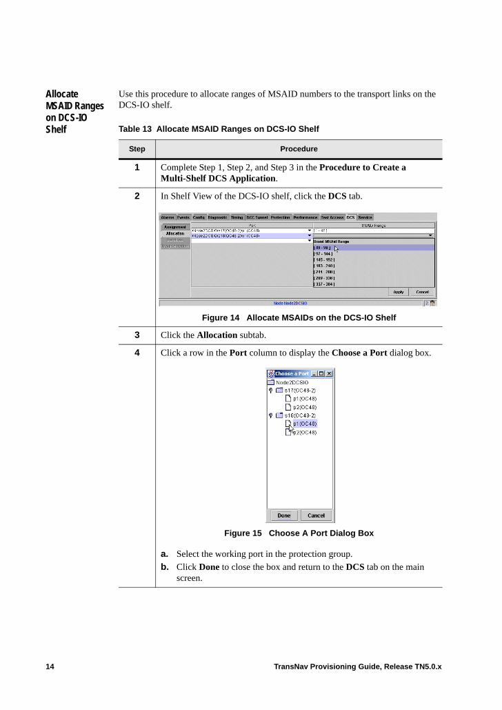
Allocate MSAID Ranges on DCS-IO Shelf
Use this procedure to allocate ranges of MSAID numbers to the transport links on the DCS-IO shelf.
Table 13 Allocate MSAID Ranges on DCS-IO Shelf
Step Procedure
1 Complete Step 1, Step 2, and Step 3 in the Procedure to Create a Multi-Shelf DCS Application.
2 In Shelf View of the DCS-IO shelf, click the DCS tab.
Figure 14 Allocate MSAIDs on the DCS-IO Shelf
3 Click the Allocation subtab.
4 Click a row in the Port column to display the Choose a Port dialog box.
Figure 15 Choose A Port Dialog Box
a. Select the working port in the protection group.
b. Click Done to close the box and return to the DCS tab on the main screen.
14 TransNav Provisioning Guide, Release TN5.0.x
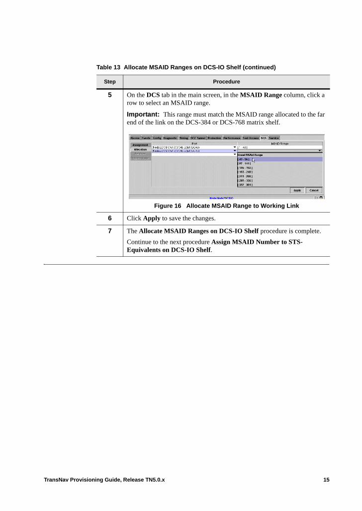
5 On the DCS tab in the main screen, in the MSAID Range column, click a row to select an MSAID range.
Important: This range must match the MSAID range allocated to the far end of the link on the DCS-384 or DCS-768 matrix shelf.
Figure 16 Allocate MSAID Range to Working Link
6 Click Apply to save the changes.
7 The Allocate MSAID Ranges on DCS-IO Shelf procedure is complete.
Continue to the next procedure Assign MSAID Number to STS- Equivalents on DCS-IO Shelf.
Table 13 Allocate MSAID Ranges on DCS-IO Shelf (continued)
Step Procedure
TransNav Provisioning Guide, Release TN5.0.x 15
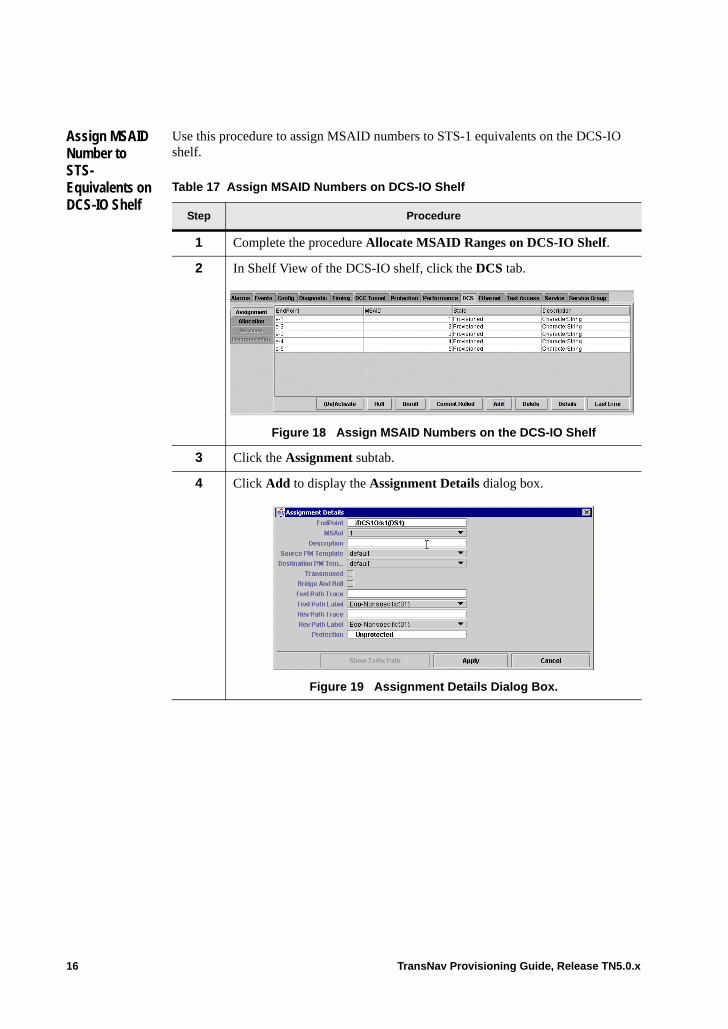
Assign MSAID Number to STS- Equivalents on DCS-IO Shelf
Use this procedure to assign MSAID numbers to STS-1 equivalents on the DCS-IO shelf.
Table 17 Assign MSAID Numbers on DCS-IO Shelf
Step Procedure
1 Complete the procedure Allocate MSAID Ranges on DCS-IO Shelf.
2 In Shelf View of the DCS-IO shelf, click the DCS tab.
Figure 18 Assign MSAID Numbers on the DCS-IO Shelf
3 Click the Assignment subtab.
4 Click Add to display the Assignment Details dialog box.
Figure 19 Assignment Details Dialog Box.
16 TransNav Provisioning Guide, Release TN5.0.x
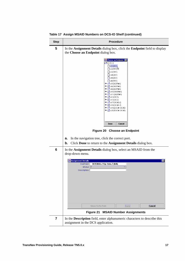
5 In the Assignment Details dialog box, click the Endpoint field to display the Choose an Endpoint dialog box.
Figure 20 Choose an Endpoint
a. In the navigation tree, click the correct port.
b. Click Done to return to the Assignment Details dialog box.
6 In the Assignment Details dialog box, select an MSAID from the drop-down menu.
Figure 21 MSAID Number Assignments
7 In the Description field, enter alphanumeric characters to describe this assignment in the DCS application.
Table 17 Assign MSAID Numbers on DCS-IO Shelf (continued)
Step Procedure
TransNav Provisioning Guide, Release TN5.0.x 17
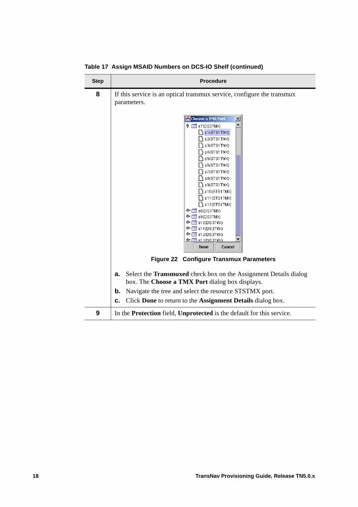
8 If this service is an optical transmux service, configure the transmux parameters.
Figure 22 Configure Transmux Parameters
a. Select the Transmuxed check box on the Assignment Details dialog box. The Choose a TMX Port dialog box displays.
b. Navigate the tree and select the resource STSTMX port.
c. Click Done to return to the Assignment Details dialog box.
9 In the Protection field, Unprotected is the default for this service.
Table 17 Assign MSAID Numbers on DCS-IO Shelf (continued)
Step Procedure
18 TransNav Provisioning Guide, Release TN5.0.x
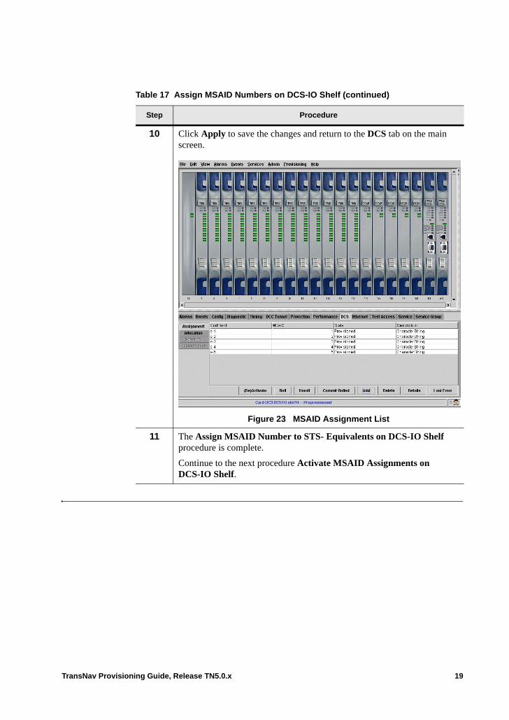
10 Click Apply to save the changes and return to the DCS tab on the main screen.
Figure 23 MSAID Assignment List
11 The Assign MSAID Number to STS- Equivalents on DCS-IO Shelf procedure is complete.
Continue to the next procedure Activate MSAID Assignments on DCS-IO Shelf.
Table 17 Assign MSAID Numbers on DCS-IO Shelf (continued)
Step Procedure
TransNav Provisioning Guide, Release TN5.0.x 19

Activate MSAID Assignments on DCS-IO Shelf
Use this procedure to activate MSAID assignments on the DCS-IO shelf.
Table 24 Activate MSAID Assignments on DCS-IO Shelf
Step Procedure
1 Complete the procedure Assign MSAID Number to STS- Equivalents on DCS-IO Shelf.
2 In Shelf View of the DCS-IO shelf, click the DCS tab and the Assignment subtab.
Figure 25 DCS Tab, Assignment Subtab, Assignment List
3 Select the MSAIDs to activate from the items listed in one of the following ways: • Select the first MSAID, press the Shift key, then press the Down Arrow
key to select a range of MSAIDs.• Use the mouse to select and highlight a range of MSAIDs.• To select random MSAIDs, use the mouse to select the first MSAID then
press CTRL and select the other MSAIDs to be activated.
4 Right-click and select Activation, then Activate from the shortcut menu to activate all of the selected MSAID assignment.
5 The Activate MSAID Assignments on DCS-IO Shelf procedure is complete.
Continue to the next procedure Create DCS Services on the DCS-384 or DCS-768 Matrix Shelf.
20 TransNav Provisioning Guide, Release TN5.0.x
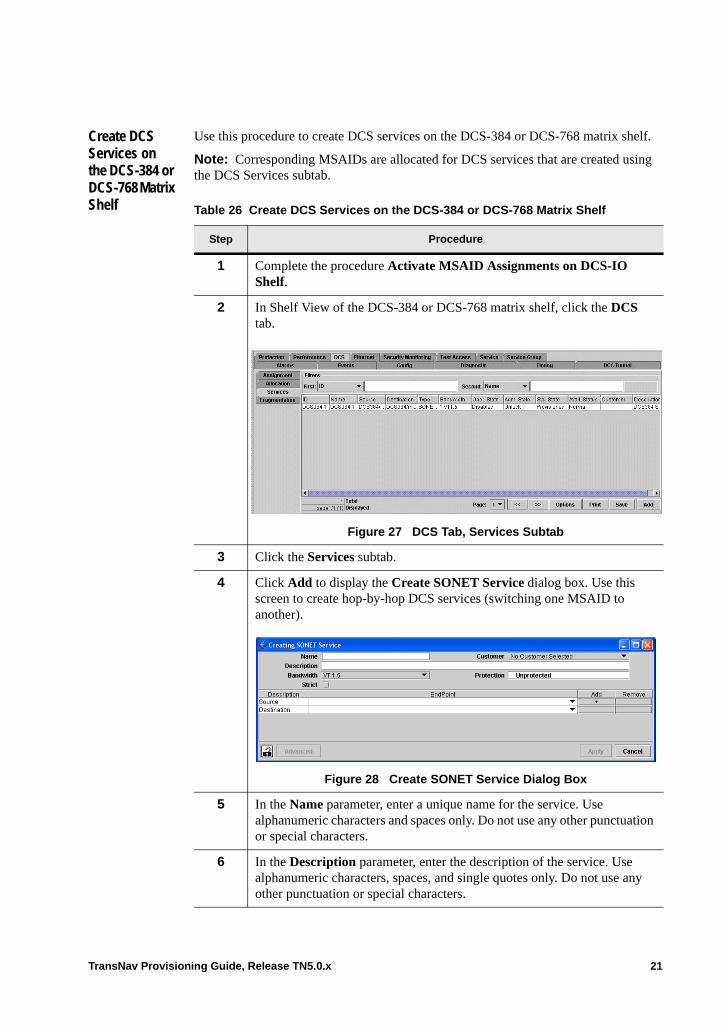
Create DCS Services on the DCS-384 or DCS-768 Matrix Shelf
Use this procedure to create DCS services on the DCS-384 or DCS-768 matrix shelf.
Note: Corresponding MSAIDs are allocated for DCS services that are created using the DCS Services subtab.
Table 26 Create DCS Services on the DCS-384 or DCS-768 Matrix Shelf
Step Procedure
1 Complete the procedure Activate MSAID Assignments on DCS-IO Shelf.
2 In Shelf View of the DCS-384 or DCS-768 matrix shelf, click the DCS tab.
Figure 27 DCS Tab, Services Subtab
3 Click the Services subtab.
4 Click Add to display the Create SONET Service dialog box. Use this screen to create hop-by-hop DCS services (switching one MSAID to another).
Figure 28 Create SONET Service Dialog Box
5 In the Name parameter, enter a unique name for the service. Use alphanumeric characters and spaces only. Do not use any other punctuation or special characters.
6 In the Description parameter, enter the description of the service. Use alphanumeric characters, spaces, and single quotes only. Do not use any other punctuation or special characters.
TransNav Provisioning Guide, Release TN5.0.x 21
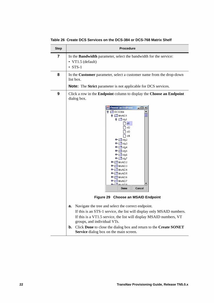
7 In the Bandwidth parameter, select the bandwidth for the service:• VT1.5 (default)• STS-1
8 In the Customer parameter, select a customer name from the drop-down list box.
Note: The Strict parameter is not applicable for DCS services.
9 Click a row in the Endpoint column to display the Choose an Endpoint dialog box.
Figure 29 Choose an MSAID Endpoint
a. Navigate the tree and select the correct endpoint. If this is an STS-1 service, the list will display only MSAID numbers. If this is a VT1.5 service, the list will display MSAID numbers, VT groups, and individual VTs.
b. Click Done to close the dialog box and return to the Create SONET Service dialog box on the main screen.
Table 26 Create DCS Services on the DCS-384 or DCS-768 Matrix Shelf
Step Procedure
22 TransNav Provisioning Guide, Release TN5.0.x
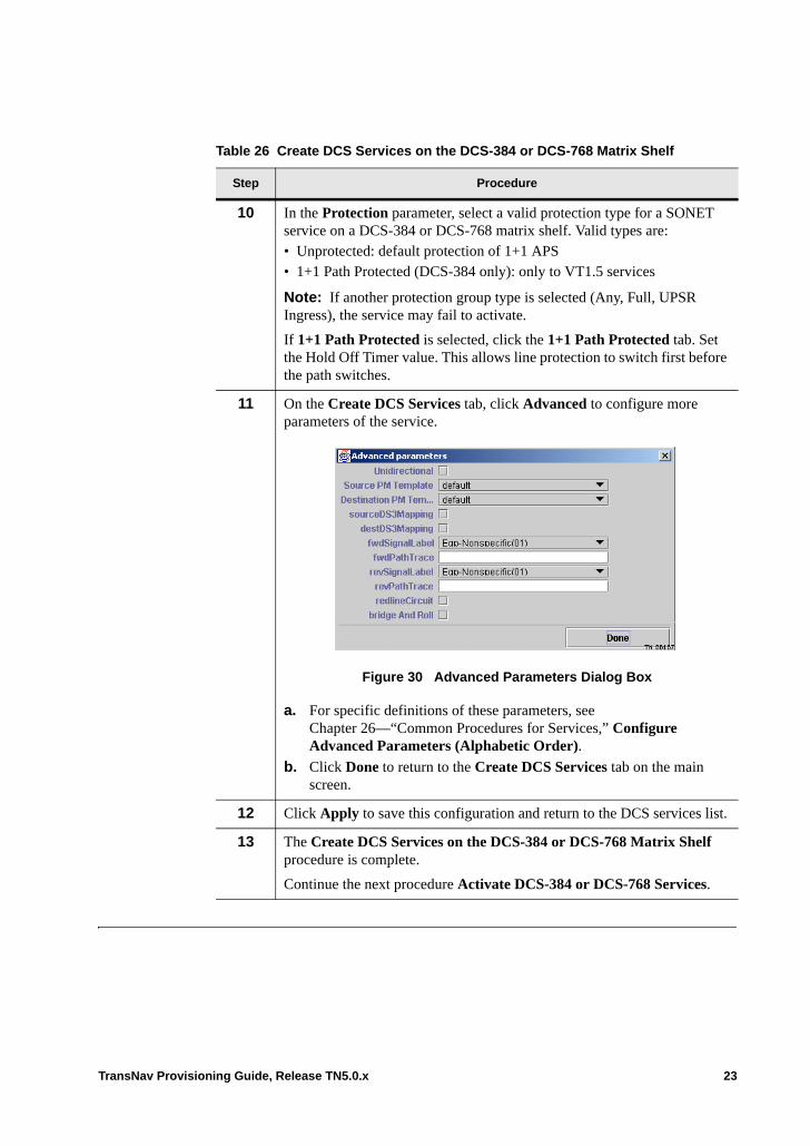
10 In the Protection parameter, select a valid protection type for a SONET service on a DCS-384 or DCS-768 matrix shelf. Valid types are:• Unprotected: default protection of 1+1 APS• 1+1 Path Protected (DCS-384 only): only to VT1.5 services
Note: If another protection group type is selected (Any, Full, UPSR Ingress), the service may fail to activate.
If 1+1 Path Protected is selected, click the 1+1 Path Protected tab. Set the Hold Off Timer value. This allows line protection to switch first before the path switches.
11 On the Create DCS Services tab, click Advanced to configure more parameters of the service.
Figure 30 Advanced Parameters Dialog Box
a. For specific definitions of these parameters, see Chapter 26—“Common Procedures for Services,” Configure Advanced Parameters (Alphabetic Order).
b. Click Done to return to the Create DCS Services tab on the main screen.
12 Click Apply to save this configuration and return to the DCS services list.
13 The Create DCS Services on the DCS-384 or DCS-768 Matrix Shelf procedure is complete.
Continue the next procedure Activate DCS-384 or DCS-768 Services.
Table 26 Create DCS Services on the DCS-384 or DCS-768 Matrix Shelf
Step Procedure
TransNav Provisioning Guide, Release TN5.0.x 23
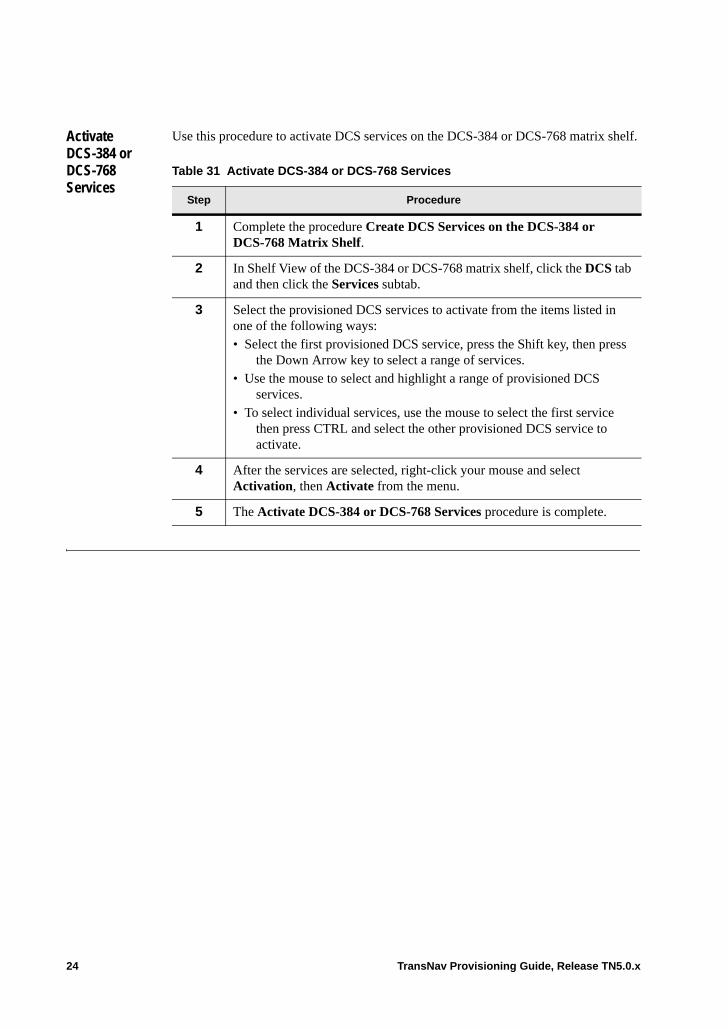
Activate DCS-384 or DCS-768 Services
Use this procedure to activate DCS services on the DCS-384 or DCS-768 matrix shelf.
Table 31 Activate DCS-384 or DCS-768 Services
Step Procedure
1 Complete the procedure Create DCS Services on the DCS-384 or DCS-768 Matrix Shelf.
2 In Shelf View of the DCS-384 or DCS-768 matrix shelf, click the DCS tab and then click the Services subtab.
3 Select the provisioned DCS services to activate from the items listed in one of the following ways: • Select the first provisioned DCS service, press the Shift key, then press
the Down Arrow key to select a range of services.• Use the mouse to select and highlight a range of provisioned DCS
services.• To select individual services, use the mouse to select the first service
then press CTRL and select the other provisioned DCS service to activate.
4 After the services are selected, right-click your mouse and select Activation, then Activate from the menu.
5 The Activate DCS-384 or DCS-768 Services procedure is complete.
24 TransNav Provisioning Guide, Release TN5.0.x
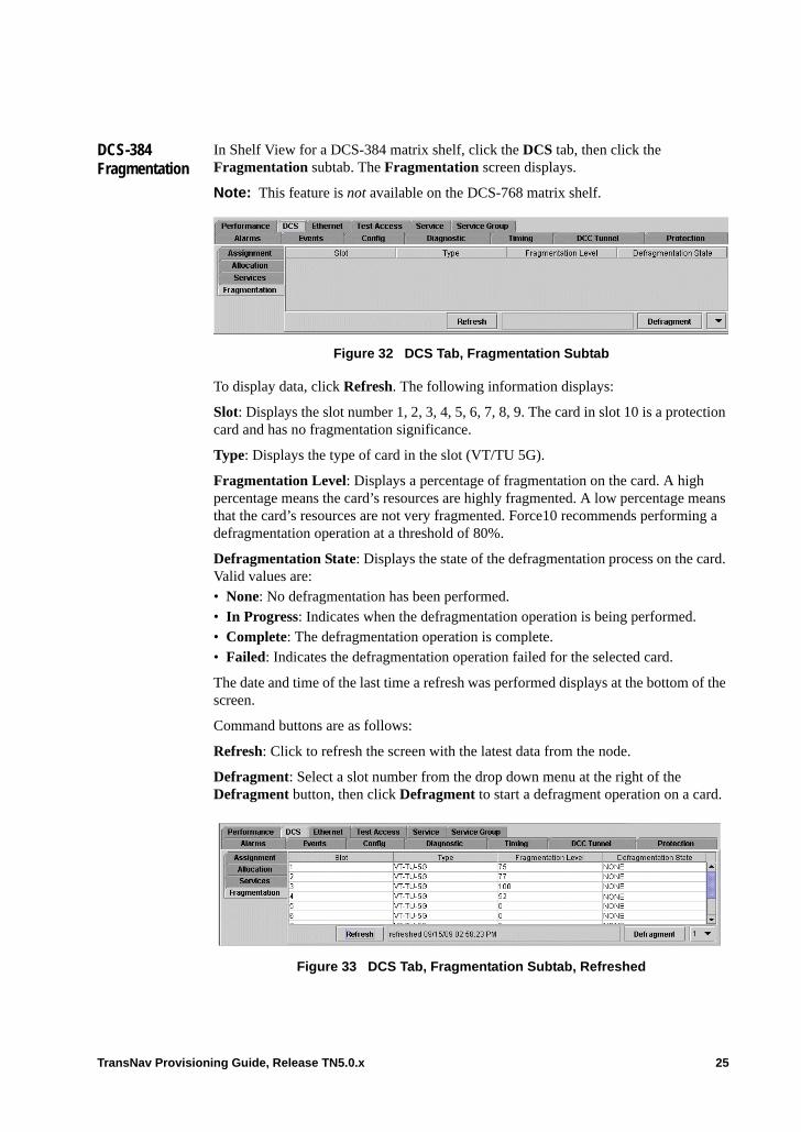
DCS-384 Fragmentation
In Shelf View for a DCS-384 matrix shelf, click the DCS tab, then click the Fragmentation subtab. The Fragmentation screen displays.
Note: This feature is not available on the DCS-768 matrix shelf.
Figure 32 DCS Tab, Fragmentation Subtab
To display data, click Refresh. The following information displays:
Slot: Displays the slot number 1, 2, 3, 4, 5, 6, 7, 8, 9. The card in slot 10 is a protection card and has no fragmentation significance.
Type: Displays the type of card in the slot (VT/TU 5G).
Fragmentation Level: Displays a percentage of fragmentation on the card. A high percentage means the card’s resources are highly fragmented. A low percentage means that the card’s resources are not very fragmented. Force10 recommends performing a defragmentation operation at a threshold of 80%.
Defragmentation State: Displays the state of the defragmentation process on the card. Valid values are: • None: No defragmentation has been performed. • In Progress: Indicates when the defragmentation operation is being performed. • Complete: The defragmentation operation is complete.• Failed: Indicates the defragmentation operation failed for the selected card.
The date and time of the last time a refresh was performed displays at the bottom of the screen.
Command buttons are as follows:
Refresh: Click to refresh the screen with the latest data from the node.
Defragment: Select a slot number from the drop down menu at the right of the Defragment button, then click Defragment to start a defragment operation on a card.
Figure 33 DCS Tab, Fragmentation Subtab, Refreshed
TransNav Provisioning Guide, Release TN5.0.x 25

26 TransNav Provisioning Guide, Release TN5.0.x
Chapter 41 Configuring Ethernet Overview
Introduction This chapter contains the following topics:• Ethernet Services Definition
– Line Services– Bridge Services– Aggregation Bridge Services– Multipoint ECC Services
• Link Integrity• Ethernet Configuration Process• Ethernet Configuration Procedure• Configuring CPE to Ethernet Information Flow• Configuring CPE to Ethernet Services Procedure
TransNav Provisioning Guide, Release TN5.0.x 1
Ethernet Services Definition
An Ethernet service is a card-level packet forwarding relationship, optionally restricted by VLAN ID, between Ethernet termination points on the same card.
The endpoints in an Ethernet service can be a mix of the following types on Traverse and TE-100 platforms: • GBE • ETH100TX• EOS port: Ethernet-over-SONET/SDH transport connections
Ethernet service endpoints that are available on Traverse only:• 10GbE (Traverse only)• GBETX (Traverse only)• EOP port: Ethernet over PDH transport connections (Traverse only)• LAG: virtual Ethernet ports built out of sets of physical Ethernet ports (Traverse
only)
There are four types of Ethernet services on a Traverse platform. The first three service types are also available on a TE-100 platform. • Line Services• Bridge Services• Aggregation Bridge Services• Multipoint ECC Services (EOP ports only)
2 TransNav Provisioning Guide, Release TN5.0.x
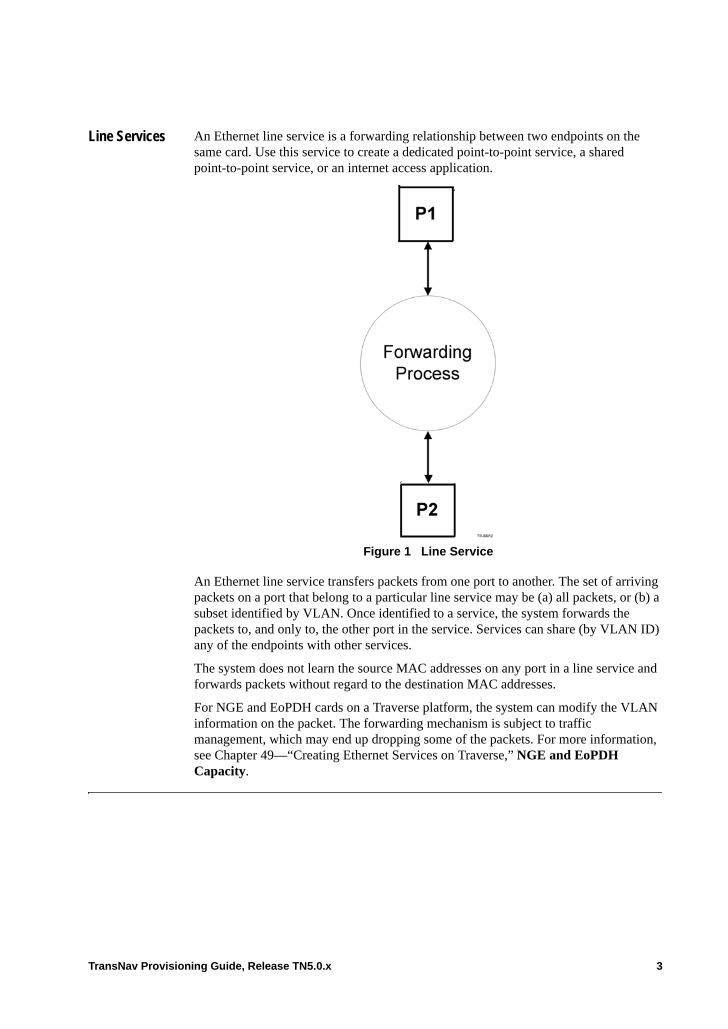
Line Services An Ethernet line service is a forwarding relationship between two endpoints on the same card. Use this service to create a dedicated point-to-point service, a shared point-to-point service, or an internet access application.
Figure 1 Line Service
An Ethernet line service transfers packets from one port to another. The set of arriving packets on a port that belong to a particular line service may be (a) all packets, or (b) a subset identified by VLAN. Once identified to a service, the system forwards the packets to, and only to, the other port in the service. Services can share (by VLAN ID) any of the endpoints with other services.
The system does not learn the source MAC addresses on any port in a line service and forwards packets without regard to the destination MAC addresses.
For NGE and EoPDH cards on a Traverse platform, the system can modify the VLAN information on the packet. The forwarding mechanism is subject to traffic management, which may end up dropping some of the packets. For more information, see Chapter 49—“Creating Ethernet Services on Traverse,” NGE and EoPDH Capacity.
TransNav Provisioning Guide, Release TN5.0.x 3
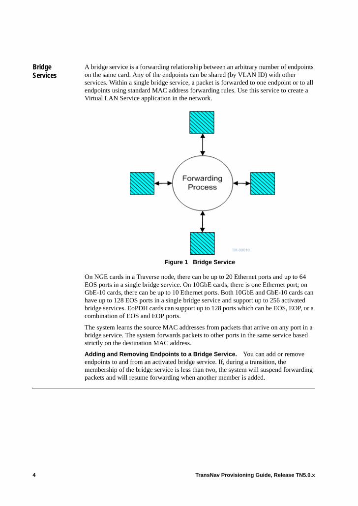
Bridge Services
A bridge service is a forwarding relationship between an arbitrary number of endpoints on the same card. Any of the endpoints can be shared (by VLAN ID) with other services. Within a single bridge service, a packet is forwarded to one endpoint or to all endpoints using standard MAC address forwarding rules. Use this service to create a Virtual LAN Service application in the network.
Figure 1 Bridge Service
On NGE cards in a Traverse node, there can be up to 20 Ethernet ports and up to 64 EOS ports in a single bridge service. On 10GbE cards, there is one Ethernet port; on GbE-10 cards, there can be up to 10 Ethernet ports. Both 10GbE and GbE-10 cards can have up to 128 EOS ports in a single bridge service and support up to 256 activated bridge services. EoPDH cards can support up to 128 ports which can be EOS, EOP, or a combination of EOS and EOP ports.
The system learns the source MAC addresses from packets that arrive on any port in a bridge service. The system forwards packets to other ports in the same service based strictly on the destination MAC address.
Adding and Removing Endpoints to a Bridge Service. You can add or remove endpoints to and from an activated bridge service. If, during a transition, the membership of the bridge service is less than two, the system will suspend forwarding packets and will resume forwarding when another member is added.
4 TransNav Provisioning Guide, Release TN5.0.x
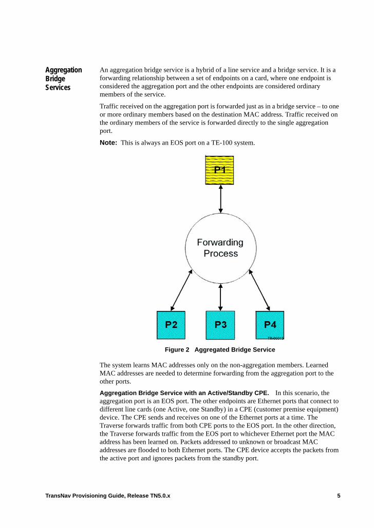
Aggregation Bridge Services
An aggregation bridge service is a hybrid of a line service and a bridge service. It is a forwarding relationship between a set of endpoints on a card, where one endpoint is considered the aggregation port and the other endpoints are considered ordinary members of the service.
Traffic received on the aggregation port is forwarded just as in a bridge service – to one or more ordinary members based on the destination MAC address. Traffic received on the ordinary members of the service is forwarded directly to the single aggregation port.
Note: This is always an EOS port on a TE-100 system.
Figure 2 Aggregated Bridge Service
The system learns MAC addresses only on the non-aggregation members. Learned MAC addresses are needed to determine forwarding from the aggregation port to the other ports.
Aggregation Bridge Service with an Active/Standby CPE. In this scenario, the aggregation port is an EOS port. The other endpoints are Ethernet ports that connect to different line cards (one Active, one Standby) in a CPE (customer premise equipment) device. The CPE sends and receives on one of the Ethernet ports at a time. The Traverse forwards traffic from both CPE ports to the EOS port. In the other direction, the Traverse forwards traffic from the EOS port to whichever Ethernet port the MAC address has been learned on. Packets addressed to unknown or broadcast MAC addresses are flooded to both Ethernet ports. The CPE device accepts the packets from the active port and ignores packets from the standby port.
TransNav Provisioning Guide, Release TN5.0.x 5
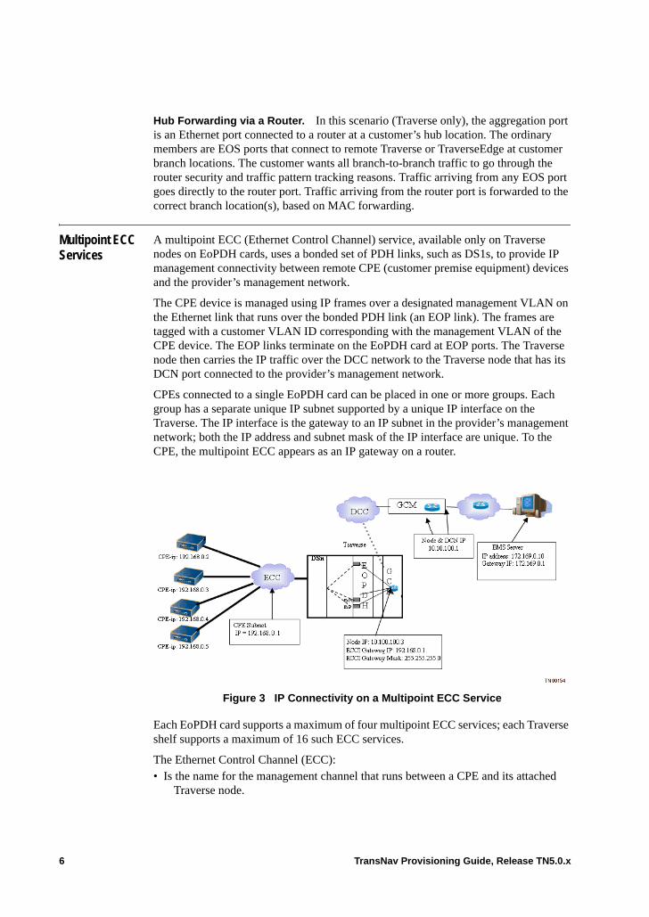
Hub Forwarding via a Router. In this scenario (Traverse only), the aggregation port is an Ethernet port connected to a router at a customer’s hub location. The ordinary members are EOS ports that connect to remote Traverse or TraverseEdge at customer branch locations. The customer wants all branch-to-branch traffic to go through the router security and traffic pattern tracking reasons. Traffic arriving from any EOS port goes directly to the router port. Traffic arriving from the router port is forwarded to the correct branch location(s), based on MAC forwarding.
Multipoint ECC Services
A multipoint ECC (Ethernet Control Channel) service, available only on Traverse nodes on EoPDH cards, uses a bonded set of PDH links, such as DS1s, to provide IP management connectivity between remote CPE (customer premise equipment) devices and the provider’s management network.
The CPE device is managed using IP frames over a designated management VLAN on the Ethernet link that runs over the bonded PDH link (an EOP link). The frames are tagged with a customer VLAN ID corresponding with the management VLAN of the CPE device. The EOP links terminate on the EoPDH card at EOP ports. The Traverse node then carries the IP traffic over the DCC network to the Traverse node that has its DCN port connected to the provider’s management network.
CPEs connected to a single EoPDH card can be placed in one or more groups. Each group has a separate unique IP subnet supported by a unique IP interface on the Traverse. The IP interface is the gateway to an IP subnet in the provider’s management network; both the IP address and subnet mask of the IP interface are unique. To the CPE, the multipoint ECC appears as an IP gateway on a router.
Figure 3 IP Connectivity on a Multipoint ECC Service
Each EoPDH card supports a maximum of four multipoint ECC services; each Traverse shelf supports a maximum of 16 such ECC services.
The Ethernet Control Channel (ECC):• Is the name for the management channel that runs between a CPE and its attached
Traverse node.
6 TransNav Provisioning Guide, Release TN5.0.x
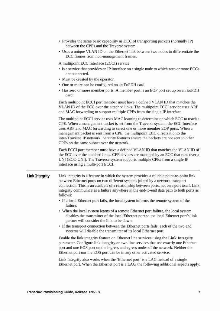
• Provides the same basic capability as DCC of transporting packets (normally IP) between the CPEs and the Traverse system.
• Uses a unique VLAN ID on the Ethernet link between two nodes to differentiate the ECC frames from non-management frames.
A multipoint ECC Interface (ECCI) service:• Is a service that provides an IP interface on a single node to which zero or more ECCs
are connected. • Must be created by the operator.• One or more can be configured on an EoPDH card.• Has zero or more member ports. A member port is an EOP port set up on an EoPDH
card.
Each multipoint ECCI port member must have a defined VLAN ID that matches the VLAN ID of the ECC over the attached links. The multipoint ECCI service uses ARP and MAC forwarding to support multiple CPEs from the single IP interface.
The multipoint ECCI service uses MAC learning to determine on which ECC to reach a CPE. When a management packet is set from the Traverse system, the ECC Interface uses ARP and MAC forwarding to select one or more member EOP ports. When a management packet is sent from a CPE, the multipoint ECC directs it onto the inter-Traverse IP network. Security features ensure the packets are not sent to other CPEs on the same subnet over the network.
Each ECCI port member must have a defined VLAN ID that matches the VLAN ID of the ECC over the attached links. CPE devices are managed by an ECC that runs over a UNI (ECC-UNI). The Traverse system supports multiple CPEs from a single IP interface using a multi-port ECCI.
Link Integrity Link integrity is a feature in which the system provides a reliable point-to-point link between Ethernet ports on two different systems joined by a network transport connection. This is an attribute of a relationship between ports, not on a port itself. Link integrity communicates a failure anywhere in the end-to-end data path to both ports as follows:• If a local Ethernet port fails, the local system informs the remote system of the
failure.• When the local system learns of a remote Ethernet port failure, the local system
disables the transmitter of the local Ethernet port so the local Ethernet port’s link partner will consider the link to be down.
• If the transport connection between the Ethernet ports fails, each of the two end systems will disable the transmitter of its local Ethernet port.
Enable the link integrity feature on Ethernet line services using the Link Integrity parameter. Configure link integrity on two line services that use exactly one Ethernet port and one EOS port on the ingress and egress nodes of the network. Neither the Ethernet port nor the EOS port can be in any other activated service.
Link Integrity also works when the ‘Ethernet port’ is a LAG instead of a single Ethernet port. When the Ethernet port is a LAG, the following additional aspects apply:
TransNav Provisioning Guide, Release TN5.0.x 7
• When a LAG fails, the condition is ‘all of the Ethernet port members in a local LAG have failed’.
• When the local system disables the transmitter, the behavior is ‘the local system disables the transmitters of all of the Ethernet ports in the local LAG’.
Link integrity is not supported on an EOP port on the EoPDH card.
When Link Integrity is used in conjunction with CEPP, verify that following information before removing the protect card of the CEPP group:• Optical links used to the carry the TDM members of the EOS ports are available and
functioning properly • SONET services that are used as the TDM members of the EOS ports are available
and functioning properly
See Chapter 49—“Creating Ethernet Services on Traverse” for information on configuring this feature
8 TransNav Provisioning Guide, Release TN5.0.x

Ethernet Configuration Process
Use this flow chart as a guideline to configure Ethernet in a Traverse system.
Figure 4 Ethernet Provisioning Flow Chart
Create Ethernet Services
Configure Ethernet TrafficManagement
End
TR-00001
Optionally, configure EOS features:RSTPLCAS
1+1 EOS port protection
Create and activateEOS members on EOS ports and
EOP members on EOP ports (Use service groups or SONET and
SDH services with endpoints onEthernet cards)
Create EOS portsCreate EOP ports (EoPDH cards only)
Optionally, configure EOP features:LCAS
1+1 EOP port protection
Start:The equipment is installed and
connected
Provision and activateSONET / SDH
path services with endpoints onEthernet cards
Optionally, configure optical andelectrical protection groups
and equipment(card and port parameters)
Optionally configure Ethernet features:Link Aggregation Groups
Auto-negotiation
TransNav Provisioning Guide, Release TN5.0.x 9
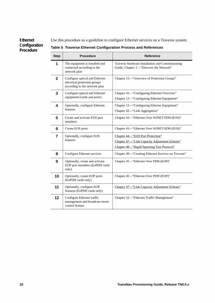
Ethernet Configuration Procedure
Use this procedure as a guideline to configure Ethernet services on a Traverse system.
Table 5 Traverse Ethernet Configuration Process and References
Step Procedure Reference
1 The equipment is installed and connected according to the network plan
Traverse Hardware Installation and Commissioning Guide, Chapter 2—“Discover the Network”
2 Configure optical and Ethernet electrical protection groups according to the network plan
Chapter 15—“Overview of Protection Groups”
3 Configure optical and Ethernet equipment (cards and ports)
Chapter 41—“Configuring Ethernet Overview”
Chapter 12—“Configuring Ethernet Equipment”
4 Optionally, configure Ethernet features
Chapter 12—“Configuring Ethernet Equipment”
Chapter 42—“Link Aggregation”
5 Create and activate EOS port members
Chapter 43—“Ethernet Over SONET/SDH (EOS)”
6 Create EOS ports Chapter 43—“Ethernet Over SONET/SDH (EOS)”
7 Optionally, configure EOS features
Chapter 44—“EOS Port Protection”
Chapter 47—“Link Capacity Adjustment Scheme”
Chapter 48—“Rapid Spanning Tree Protocol”
8 Configure Ethernet services Chapter 49—“Creating Ethernet Services on Traverse”
9 Optionally, create and activate EOP port members (EoPDH cards only)
Chapter 45—“Ethernet Over PDH (EOP)”
10 Optionally, create EOP ports (EoPDH cards only)
Chapter 45—“Ethernet Over PDH (EOP)”
11 Optionally, configure EOP features (EoPDH cards only)
Chapter 47—“Link Capacity Adjustment Scheme”
12 Configure Ethernet traffic management and broadcast storm control feature
Chapter 52—“Ethernet Traffic Management”
10 TransNav Provisioning Guide, Release TN5.0.x

Configuring CPE to Ethernet Information Flow
Use this flow chart as a guideline to configure the flow of information from a customer premise equipment (CPE) device to Ethernet services in a Traverse system.
Figure 6 Ethernet Provisioning Flow Chart
Configure Ethernet traffic management for EOP ports
End
TR-00055
Create EOP ports and activate EOP members
(EoPDH cards only)
Start:The equipment is installed and
connected
Optionally, configure optical and electrical equipment
(card and port parameters)
Create Ethernet Multipoint ECC services
TransNav Provisioning Guide, Release TN5.0.x 11
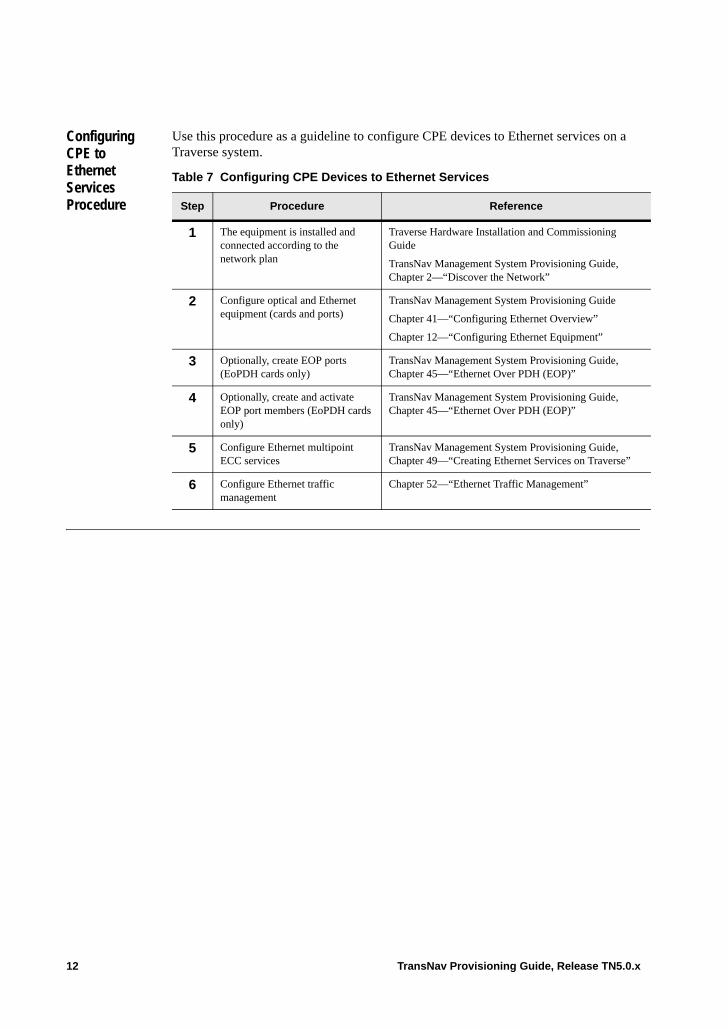
Configuring CPE to Ethernet Services Procedure
Use this procedure as a guideline to configure CPE devices to Ethernet services on a Traverse system.
Table 7 Configuring CPE Devices to Ethernet Services
Step Procedure Reference
1 The equipment is installed and connected according to the network plan
Traverse Hardware Installation and Commissioning Guide
TransNav Management System Provisioning Guide, Chapter 2—“Discover the Network”
2 Configure optical and Ethernet equipment (cards and ports)
TransNav Management System Provisioning Guide
Chapter 41—“Configuring Ethernet Overview”
Chapter 12—“Configuring Ethernet Equipment”
3 Optionally, create EOP ports (EoPDH cards only)
TransNav Management System Provisioning Guide, Chapter 45—“Ethernet Over PDH (EOP)”
4 Optionally, create and activate EOP port members (EoPDH cards only)
TransNav Management System Provisioning Guide, Chapter 45—“Ethernet Over PDH (EOP)”
5 Configure Ethernet multipoint ECC services
TransNav Management System Provisioning Guide, Chapter 49—“Creating Ethernet Services on Traverse”
6 Configure Ethernet traffic management
Chapter 52—“Ethernet Traffic Management”
12 TransNav Provisioning Guide, Release TN5.0.x
Chapter 42 Link Aggregation
Introduction This chapter contains the following topics:• Link Aggregation• Link Aggregation Control Protocol• Guidelines to Configure Link Aggregation• LAG Capacity Changes• Before You Begin• Create a Link Aggregation Group• Edit LACP Values• View the Link Aggregation Control Protocol Status of LAG
Link Aggregation
Clause 43 in IEEE 802.3 defines a link aggregation group (LAG) as Ethernet links grouped together to appear as if they were a single logical link. On the Traverse system, each logical link can consist of up to eight customer-facing Ethernet ports of full duplex point-to-point links operating at the same data rate.
Use a LAG (also known as an Etherchannel) on an Ethernet service in the same manner as an Ethernet port. However, a LAG has more capacity and availability than a regular Ethernet port. A LAG can carry more data than an individual port and will continue to operate at reduced capacity when individual ports fail. Configure a service-related attribute of LAG in a service (such as Classifier or Policer) in the same manner as you would configure service-related attributes of an Ethernet port.
Link Aggregation, in accordance with the standard, assures that all frames in the same ‘conversation’ are sent out the same link to minimize packet reordering. For the Traverse Ethernet cards, ‘conversation’ is defined as “all frames that share the same source MAC address, destination MAC address, and (if the frame contains an IP packet) source IP address and destination IP address.”
When any of the links in the LAG fails, the system transfers the traffic from the failed link to another link that is still in operation. This adjustment is automatic and does not require operator action.
The operator configures a LAG on an Ethernet card. The system propagates the values in the LAG parameters to the member ports in the LAG. The individual Ethernet ports in the LAG cannot be used as separate ports. If a LAG on an activated Ethernet service has no members, an error message displays.
TransNav Provisioning Guide, Release TN5.0.x 1
Link Aggregation Control Protocol
Link Aggregation Control Protocol (LACP) extends the LAG capabilities of the GbE-10 card on the Traverse system by providing coordinated link memberships of the LAG. This allows easier configuration when interoperating with non-Force10 equipment. LAGs must be set up on the GbE-10 card prior to configuring LACP. Predefined system and link identification are used by LACP to prevent misconnected interfaces from being added to a LAG. Additionally, the Link Aggregation protocols defined in IEEE 802.3 clause 43 and annexes 43A, 43B, and 43C ensure that LACP traffic loads are balanced across all of the ports currently in a LAG.
An LACP group can be designated as active or standby with coordinated link protection. If an active LACP group fails, the system transfers the traffic from the failed link to another link that is active. As with LAGs, this adjustment is automatic and does not require operator action. Standby links are automatically assigned by the system. To connect the LAGs and ensure communication, the port priorities must be manually assigned.
When LACP is enabled, any non-LACP packets with a slow protocol MAC address, such as Link OAM (IEEE 802.3 clause 57) packets, are discarded. When LACP is not enabled on a port, both LACP packets and Link OAM packets are forwarded as customer traffic. When LACP is enabled, Traverse processes the LACP packets but discards the Link OAM packets which are not supported in this release. The dropped packets are not reported on a performance monitoring report.
Guidelines to Configure Link Aggregation
Before you configure a LAG, consider the following guidelines:• Up to 8 ports in one LAG on an NGE, GbE-10, or EoPDH card; only 1 port on a
10GbE card. One port is termed a member of the LAG.• Only 1 LAG on the same 10GbE card, up to 10 LAGs on the same GbE-10 card, or
up to 20 LAGs on the same NGE or EoPDH card. • Member ports must of the same type: either ETH100TX or GBE. Optical and
electrical GBE ports can be in the same LAG. • GbE-10 cards have different numbers of physical ports and will have
correspondingly different numbers of LAGs.• Ports can be dynamically added to or removed from a LAG.• Configured LAG member parameters are propagated to the individual ports. The
system propagates a configured LAG member attribute to all of the individual ports in the LAG. These attributes cannot be changed or configured directly while the port is in a LAG.
• All ports in the LAG must be full duplex.• An Ethernet port already in an activated Ethernet service or with a terminal loopback
on the port cannot be a member of a LAG. • A service will not activate if one member (Ethernet port) is already in a LAG. • A LAG cannot be deleted if it is currently in an activated Ethernet service.• When the forwarding rules for a service cause a packet to be forwarded to a LAG and
when that LAG is in an alarm condition, then the system drops the packet.• If the link partner of a LAG is connected to third-party equipment, the link partners
must be configured to the equivalent of a LAG using the same set of ports.• To connect the LAGs and ensure communication, the port priorities on each end of
the LAG must be manually assigned.
2 TransNav Provisioning Guide, Release TN5.0.x
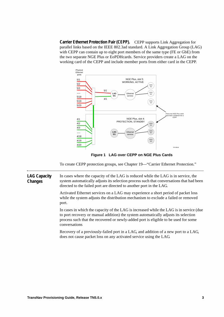
Carrier Ethernet Protection Pair (CEPP). CEPP supports Link Aggregation for parallel links based on the IEEE 802.3ad standard. A Link Aggregation Group (LAG) with CEPP can contain up to eight port members of the same type (FE or GbE) from the two separate NGE Plus or EoPDHcards. Service providers create a LAG on the working card of the CEPP and include member ports from either card in the CEPP.
Figure 1 LAG over CEPP on NGE Plus Cards
To create CEPP protection groups, see Chapter 19—“Carrier Ethernet Protection.”
LAG Capacity Changes
In cases where the capacity of the LAG is reduced while the LAG is in service, the system automatically adjusts its selection process such that conversations that had been directed to the failed port are directed to another port in the LAG.
Activated Ethernet services on a LAG may experience a short period of packet loss while the system adjusts the distribution mechanism to exclude a failed or removed port.
In cases in which the capacity of the LAG is increased while the LAG is in service (due to port recovery or manual addition) the system automatically adjusts its selection process such that the recovered or newly-added port is eligible to be used for some conversations
Recovery of a previously-failed port in a LAG, and addition of a new port to a LAG, does not cause packet loss on any activated service using the LAG.
LAG5/1
NGE Plus, slot 5:WORKING, ACTIVE
NGE Plus, slot 4:PROTECTION, STANDBY
5/1
5/2
4/1
5/3
4/2
5/18
5/19
5/20
4/18
4/19
4/20
4/3
...
... 5/1
4/1
Ethernetservice
EOS5/1
EOS5/2
EOS5/3
LAG5/1
EOS5/1
EOS5/2
EOS5/3
Ethernetservice
These two NGE Plus cardshave been combined into a
CEPP
TR 00040
PhysicalEthernet
ports
TransNav Provisioning Guide, Release TN5.0.x 3
Before You Begin
Review the information in this topic before you configure link aggregation groups on a Traverse shelf.
Note: LACP is only available on GbE-10 cards.
Table 2 Link Aggregation Requirements
Requirement Reference
• Read the information in Chapter 1—“TN5.0.x Provisioning Overview”.
• Ensure the requirements in Chapter 2—“Discover the Network,” Before You Start Provisioning Your Network are met.
• Hardware
• The information in this section strictly pertains to the following Ethernet cards: NGE, NGE Plus, Gigabit Ethernet, EoPDH
• Traverse Hardware Guide
• The correct ECMs are installed. • Traverse Cabling and Cabling Specifications Guide, Chapter 16—“Ethernet (Electrical) Cabling Procedures”
• The physical network is connected. • Traverse Hardware Installation and Commissioning Guide
• Software
• Verify the network is discovered. • Chapter 2—“Discover the Network”
• Ensure the timing is configured. • Chapter 3—“Configure Network Timing”
• Ensure the optical protection groups are configured.
• Chapter 15—“Overview of Protection Groups”
• If this card is part of a 1:1 Ethernet electrical protection group or a Carrier Ethernet Protection Pair, the protection groups must be configured.
• Configure the LAG on the working card.
• Chapter 18—“Creating Equipment Protection Groups”
• Ethernet cards and interfaces are configured. • Chapter 12—“Configuring Ethernet Equipment”
4 TransNav Provisioning Guide, Release TN5.0.x
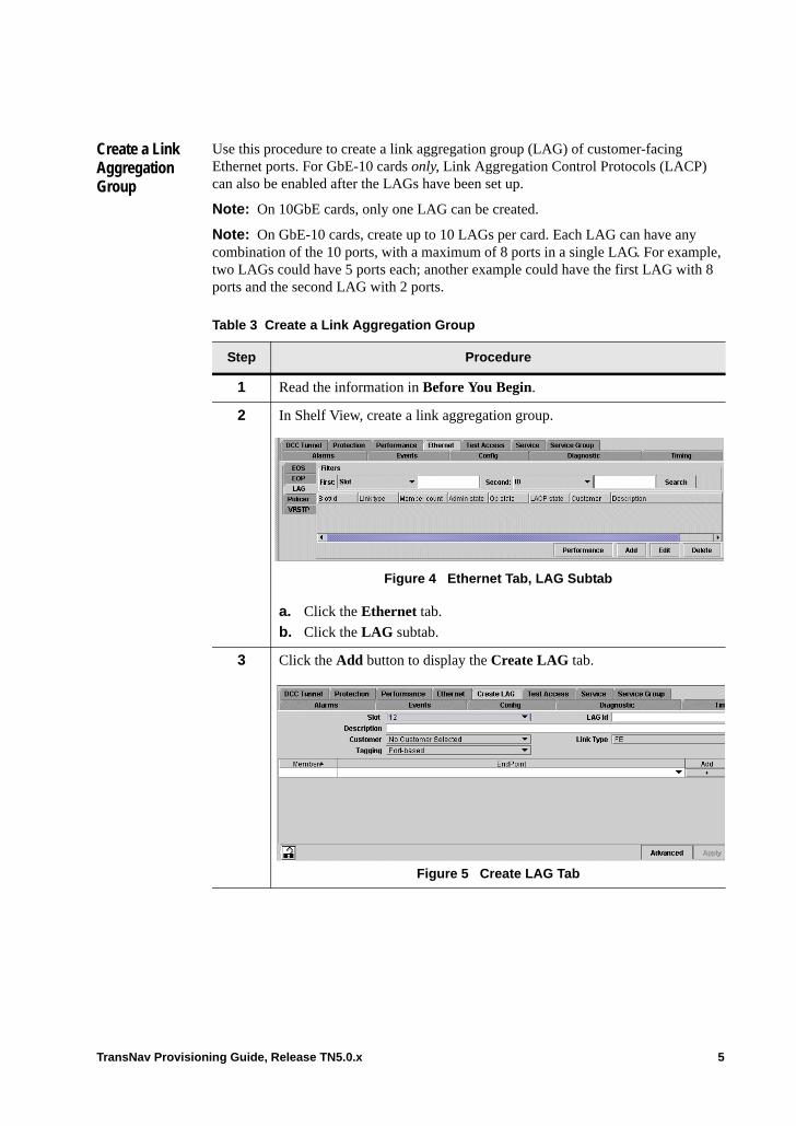
Create a Link Aggregation Group
Use this procedure to create a link aggregation group (LAG) of customer-facing Ethernet ports. For GbE-10 cards only, Link Aggregation Control Protocols (LACP) can also be enabled after the LAGs have been set up.
Note: On 10GbE cards, only one LAG can be created.
Note: On GbE-10 cards, create up to 10 LAGs per card. Each LAG can have any combination of the 10 ports, with a maximum of 8 ports in a single LAG. For example, two LAGs could have 5 ports each; another example could have the first LAG with 8 ports and the second LAG with 2 ports.
Table 3 Create a Link Aggregation Group
Step Procedure
1 Read the information in Before You Begin.
2 In Shelf View, create a link aggregation group.
Figure 4 Ethernet Tab, LAG Subtab
a. Click the Ethernet tab.
b. Click the LAG subtab.
3 Click the Add button to display the Create LAG tab.
Figure 5 Create LAG Tab
TransNav Provisioning Guide, Release TN5.0.x 5
4 Configure the attributes of the LAG:• Slot: Select the slot number of the card on which to create this LAG. If
this card is in a 1:1 equipment protection group or a Carrier Ethernet Protection Pair (CEPP), select the working card.
• LAG ID (Required field): The identification number for the LAG. Enter a numeric character string from 1 to 10. Do not enter letters or special characters.
• Description: Enter an alphanumeric character string to describe this LAG in the list on the Ethernet tab.
• Customer: Select from a list of defined customers.• Link Type: Select the types of ports to be included in this LAG. Member
ports must of the same type.– FE. Select FE to create a LAG of fast Ethernet ports.– GbE: Select for 10GbE and GbE-10 cards.Configure the Tagging type for this port:– Port-based (default): Every packet on this port is considered to
belong to the same service, regardless of whether or not the packet has a customer VLAN tag. Customer VLAN tags are not significant for service definition.
– Customer-tagged: Every packet on this port is assumed to have a VLAN tag that identifies its service in the customer network (customer VLAN tag). This tag is significant for Traverse Ethernet service definition. Customer VLAN tags mean the service provider can have multiple Ethernet streams sharing the same port identified by a separate customer VLAN ID.
– Service-tagged: Every packet on this port is assumed to have a service provider VLAN ID that identifies its Ethernet service within the service provider network. Service provider VLAN tags are never used on customer-facing ports. The service provider VLAN tag optionally carries packet class of service and drop precedence information used within the service provider network and not conveyed to the end customer.
For GbE-10 cards only, the following additional parameters are available:• LACP Enabled: Select the checkbox to enable Link Aggregation
Control Protocol on this LAG.• System Priority: Displays if the LACP Enabled checkbox is selected.
A smaller system priority value determines the priority if the port priority values are the same. Enter a value between 1 and 65535. The default is 32768.
• Max Active Members: Displays if the LACP Enabled checkbox is selected. Enter the number of LAG members you want to make active. The remaining LAG members are in standby. Valid values are 1 through 8. The default is 8.
Table 3 Create a Link Aggregation Group (continued)
Step Procedure
6 TransNav Provisioning Guide, Release TN5.0.x
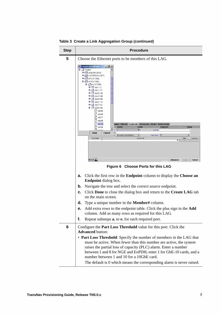
5 Choose the Ethernet ports to be members of this LAG.
Figure 6 Choose Ports for this LAG
a. Click the first row in the Endpoint column to display the Choose an Endpoint dialog box.
b. Navigate the tree and select the correct source endpoint.
c. Click Done to close the dialog box and return to the Create LAG tab on the main screen.
d. Type a unique number in the Member# column.
e. Add extra rows to the endpoint table. Click the plus sign in the Add column. Add as many rows as required for this LAG.
f. Repeat substeps a. to e. for each required port.
6 Configure the Part Loss Threshold value for this port. Click the Advanced button: • Part Loss Threshold: Specify the number of members in the LAG that
must be active. When fewer than this number are active, the system raises the partial loss of capacity (PLC) alarm. Enter a number between 1 and 8 for NGE and EoPDH; enter 1 for GbE-10 cards, and a number between 1 and 10 for a 10GbE card.The default is 0 which means the corresponding alarm is never raised.
Table 3 Create a Link Aggregation Group (continued)
Step Procedure
TransNav Provisioning Guide, Release TN5.0.x 7
7 In the Queuing Policy parameter, specify how the queues are managed. Select one of the following values.
Note: Setting the Queuing Policy for EoPDH cards can greatly affect traffic management on EOP ports. For more information, see Chapter 52—“Ethernet Traffic Management,” Managing Traffic on EOP Ports. • FIFO (default): First-in-first-out. Select this queuing policy to schedule
all packets for transmission based on the FIFO algorithm. All traffic uses CoS1. Optionally, configure whether shaping should be employed using the FIFO Shaping Enable and the FIFO Shape Rate parameters. Go to Step 8.
• Priority: Select this queuing policy to schedule all packets for transmission based on strict priority, using three classes of service. There are three priorities: Highest priority traffic uses CoS1, medium priority traffic uses CoS2, and low priority traffic uses CoS3.
• WFQ: Weighted fair queuing. Select this queuing policy to guarantee a specific amount of the port’s bandwidth when there is congestion on the port. WFQ uses four classes of service and the guarantees are specified as weights. If the value in this parameter is WFQ, specify the weights in the four WFQ CoS weight {1 | 2 | 3 | 4} parameters. Go to Step 9.
8 If FIFO is the value in the Queuing Priority parameter, configure the following parameters:• FIFO Shape Enable: Specify if the system will use the number in the
FIFO Shaping Rate parameter to shape the traffic being transmitted onto the port. Valid values are Disabled (default) and Enabled.
• FIFO Shaping Rate: If the FIFO Shaping Rate is enabled, specify a number between 1 and 1000 Mbps for NGE cards. For 10GbE and GbE-10 cards, specify a number between 1 and 10,000 Mbps; default for 10GbE is 10000, default for GbE-10 is 1000.
Table 3 Create a Link Aggregation Group (continued)
Step Procedure
8 TransNav Provisioning Guide, Release TN5.0.x
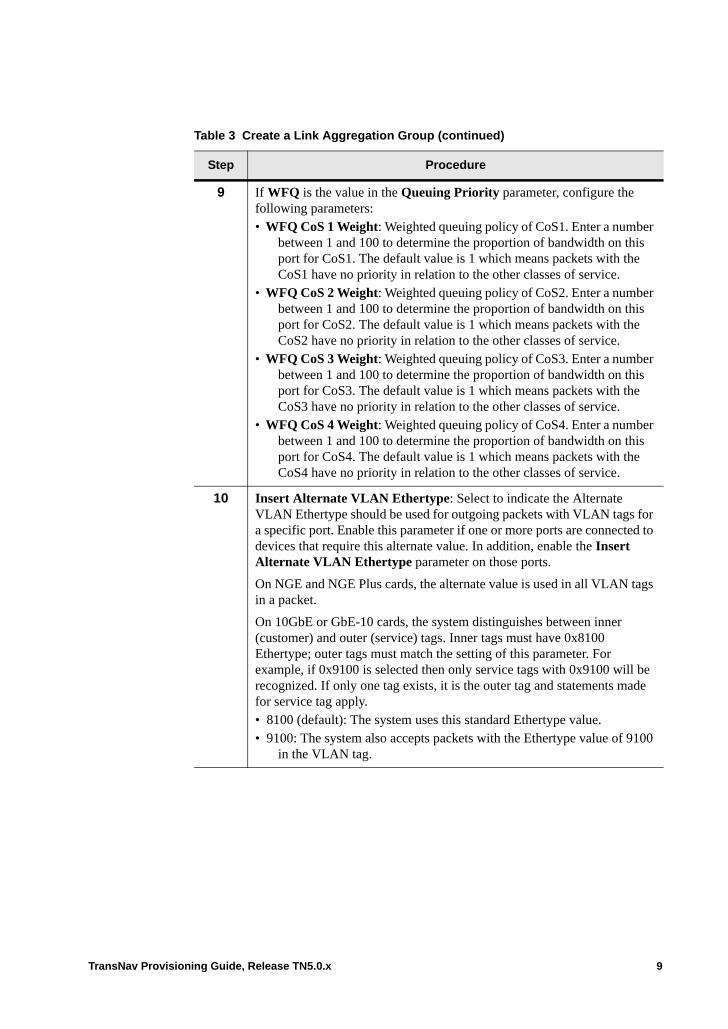
9 If WFQ is the value in the Queuing Priority parameter, configure the following parameters:• WFQ CoS 1 Weight: Weighted queuing policy of CoS1. Enter a number
between 1 and 100 to determine the proportion of bandwidth on this port for CoS1. The default value is 1 which means packets with the CoS1 have no priority in relation to the other classes of service.
• WFQ CoS 2 Weight: Weighted queuing policy of CoS2. Enter a number between 1 and 100 to determine the proportion of bandwidth on this port for CoS2. The default value is 1 which means packets with the CoS2 have no priority in relation to the other classes of service.
• WFQ CoS 3 Weight: Weighted queuing policy of CoS3. Enter a number between 1 and 100 to determine the proportion of bandwidth on this port for CoS3. The default value is 1 which means packets with the CoS3 have no priority in relation to the other classes of service.
• WFQ CoS 4 Weight: Weighted queuing policy of CoS4. Enter a number between 1 and 100 to determine the proportion of bandwidth on this port for CoS4. The default value is 1 which means packets with the CoS4 have no priority in relation to the other classes of service.
10 Insert Alternate VLAN Ethertype: Select to indicate the Alternate VLAN Ethertype should be used for outgoing packets with VLAN tags for a specific port. Enable this parameter if one or more ports are connected to devices that require this alternate value. In addition, enable the Insert Alternate VLAN Ethertype parameter on those ports.
On NGE and NGE Plus cards, the alternate value is used in all VLAN tags in a packet.
On 10GbE or GbE-10 cards, the system distinguishes between inner (customer) and outer (service) tags. Inner tags must have 0x8100 Ethertype; outer tags must match the setting of this parameter. For example, if 0x9100 is selected then only service tags with 0x9100 will be recognized. If only one tag exists, it is the outer tag and statements made for service tag apply.• 8100 (default): The system uses this standard Ethertype value. • 9100: The system also accepts packets with the Ethertype value of 9100
in the VLAN tag.
Table 3 Create a Link Aggregation Group (continued)
Step Procedure
TransNav Provisioning Guide, Release TN5.0.x 9
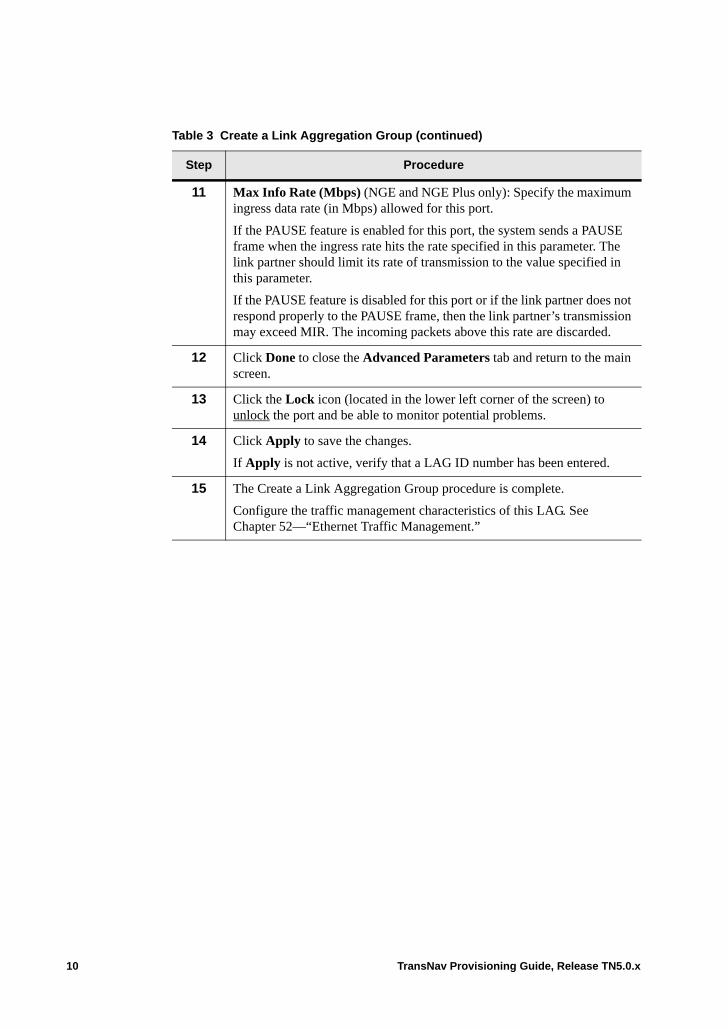
11 Max Info Rate (Mbps) (NGE and NGE Plus only): Specify the maximum ingress data rate (in Mbps) allowed for this port.
If the PAUSE feature is enabled for this port, the system sends a PAUSE frame when the ingress rate hits the rate specified in this parameter. The link partner should limit its rate of transmission to the value specified in this parameter.
If the PAUSE feature is disabled for this port or if the link partner does not respond properly to the PAUSE frame, then the link partner’s transmission may exceed MIR. The incoming packets above this rate are discarded.
12 Click Done to close the Advanced Parameters tab and return to the main screen.
13 Click the Lock icon (located in the lower left corner of the screen) to unlock the port and be able to monitor potential problems.
14 Click Apply to save the changes.
If Apply is not active, verify that a LAG ID number has been entered.
15 The Create a Link Aggregation Group procedure is complete.
Configure the traffic management characteristics of this LAG. See Chapter 52—“Ethernet Traffic Management.”
Table 3 Create a Link Aggregation Group (continued)
Step Procedure
10 TransNav Provisioning Guide, Release TN5.0.x
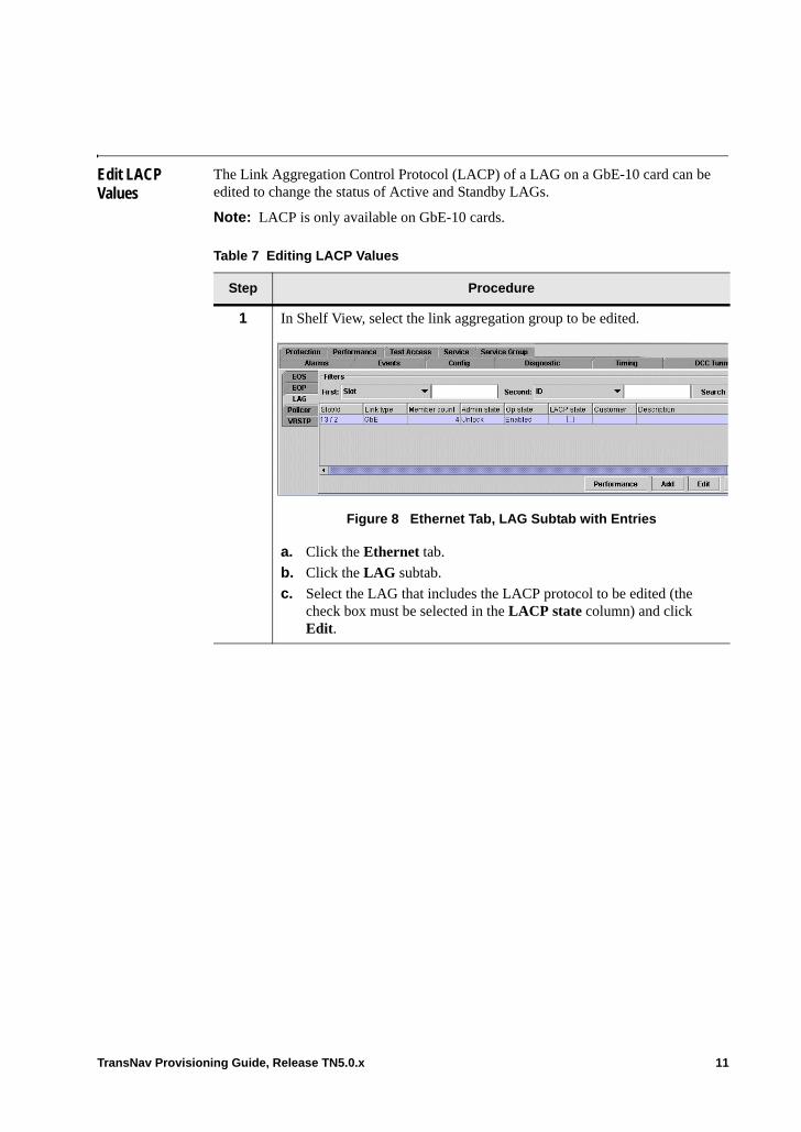
Edit LACP Values
The Link Aggregation Control Protocol (LACP) of a LAG on a GbE-10 card can be edited to change the status of Active and Standby LAGs.
Note: LACP is only available on GbE-10 cards.
Table 7 Editing LACP Values
Step Procedure
1 In Shelf View, select the link aggregation group to be edited.
Figure 8 Ethernet Tab, LAG Subtab with Entries
a. Click the Ethernet tab.
b. Click the LAG subtab.
c. Select the LAG that includes the LACP protocol to be edited (the check box must be selected in the LACP state column) and click Edit.
TransNav Provisioning Guide, Release TN5.0.x 11
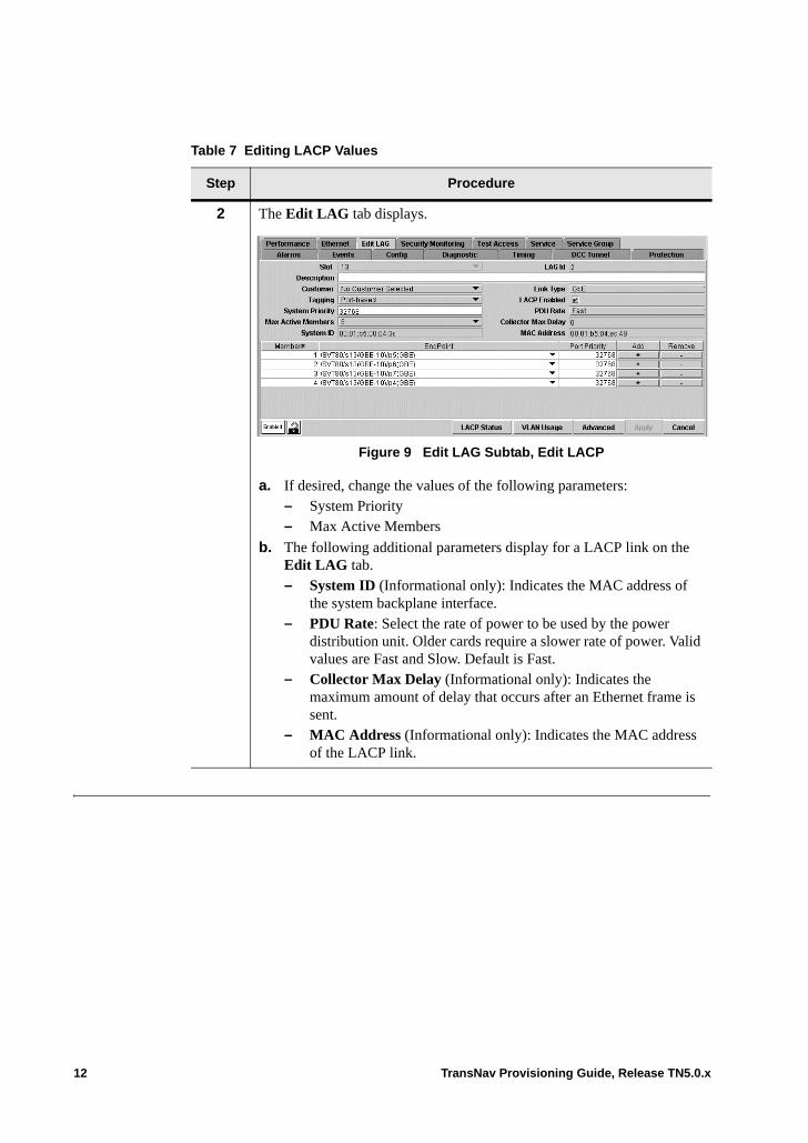
2 The Edit LAG tab displays.
Figure 9 Edit LAG Subtab, Edit LACP
a. If desired, change the values of the following parameters: – System Priority – Max Active Members
b. The following additional parameters display for a LACP link on the Edit LAG tab. – System ID (Informational only): Indicates the MAC address of
the system backplane interface.– PDU Rate: Select the rate of power to be used by the power
distribution unit. Older cards require a slower rate of power. Valid values are Fast and Slow. Default is Fast.
– Collector Max Delay (Informational only): Indicates the maximum amount of delay that occurs after an Ethernet frame is sent.
– MAC Address (Informational only): Indicates the MAC address of the LACP link.
Table 7 Editing LACP Values
Step Procedure
12 TransNav Provisioning Guide, Release TN5.0.x
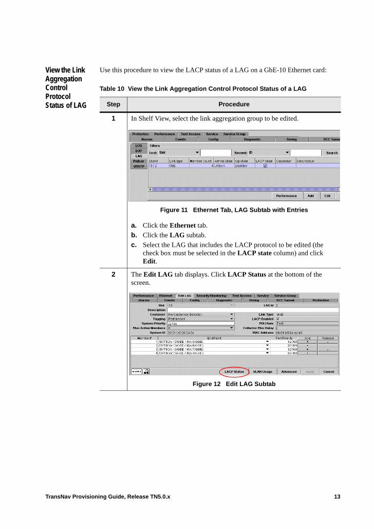
View the Link Aggregation Control Protocol Status of LAG
Use this procedure to view the LACP status of a LAG on a GbE-10 Ethernet card:
Table 10 View the Link Aggregation Control Protocol Status of a LAG
Step Procedure
1 In Shelf View, select the link aggregation group to be edited.
Figure 11 Ethernet Tab, LAG Subtab with Entries
a. Click the Ethernet tab.
b. Click the LAG subtab.
c. Select the LAG that includes the LACP protocol to be edited (the check box must be selected in the LACP state column) and click Edit.
2 The Edit LAG tab displays. Click LACP Status at the bottom of the screen.
Figure 12 Edit LAG Subtab
TransNav Provisioning Guide, Release TN5.0.x 13
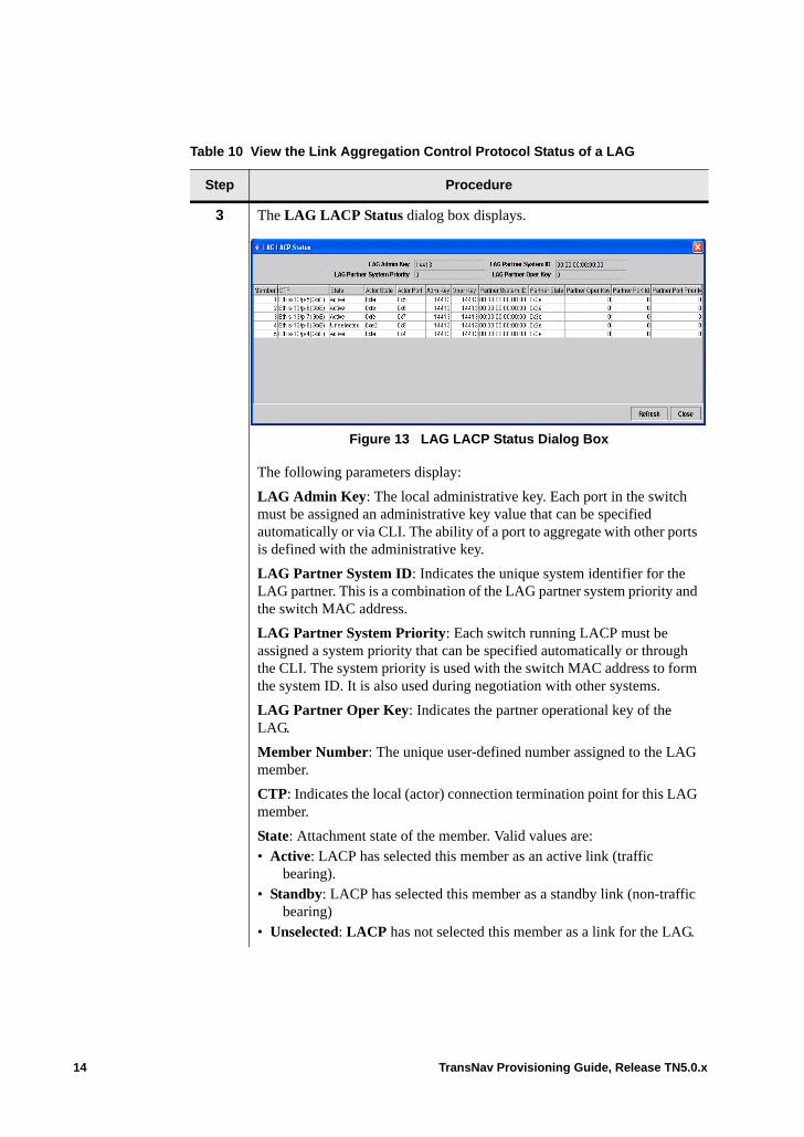
3 The LAG LACP Status dialog box displays.
Figure 13 LAG LACP Status Dialog Box
The following parameters display:
LAG Admin Key: The local administrative key. Each port in the switch must be assigned an administrative key value that can be specified automatically or via CLI. The ability of a port to aggregate with other ports is defined with the administrative key.
LAG Partner System ID: Indicates the unique system identifier for the LAG partner. This is a combination of the LAG partner system priority and the switch MAC address.
LAG Partner System Priority: Each switch running LACP must be assigned a system priority that can be specified automatically or through the CLI. The system priority is used with the switch MAC address to form the system ID. It is also used during negotiation with other systems.
LAG Partner Oper Key: Indicates the partner operational key of the LAG.
Member Number: The unique user-defined number assigned to the LAG member.
CTP: Indicates the local (actor) connection termination point for this LAG member.
State: Attachment state of the member. Valid values are: • Active: LACP has selected this member as an active link (traffic
bearing).• Standby: LACP has selected this member as a standby link (non-traffic
bearing)• Unselected: LACP has not selected this member as a link for the LAG.
Table 10 View the Link Aggregation Control Protocol Status of a LAG
Step Procedure
14 TransNav Provisioning Guide, Release TN5.0.x

Actor State: Indicates the local actor state in hexadecimal format.
Actor Port: Indicates the actor port number of the LAG member.
Adm Key: Indicates the local administrative key.
Oper Key: The local operational key.
Partner System ID: The partner system ID in MAC address format.
Partner State: Indicates the partner actor state in hexadecimal format.
Partner Oper Key: Indicates the partner operational key.
Partner Port ID: The partner port ID. Valid values are 0 to 65535. The default is 0.
Partner Port Priority: Indicates the partner port priority. Valid values are 0 to 65535. The default is 32768.
4 Click Refresh to refresh the data displayed or click Close to close the dialog box and return to the previous screen.
Table 10 View the Link Aggregation Control Protocol Status of a LAG
Step Procedure
TransNav Provisioning Guide, Release TN5.0.x 15

16 TransNav Provisioning Guide, Release TN5.0.x
Chapter 43 Ethernet Over SONET/SDH (EOS)
Introduction This chapter contains the following topics:• Ethernet over SONET/SDH Required Connections• EOS Ports• Virtual Concatenation• Before You Begin• Guidelines to Configure EOS Ports• Configure EOS Port Members• Configure Service Groups• Creating EOS Ports
TransNav Provisioning Guide, Release TN5.0.x 1
Ethernet over SONET/SDH Required Connections
Ethernet traffic travels over SONET or SDH connections. Creating Ethernet over SONET/SDH (EOS) connections require two components:• EOS ports. An EOS port is a port-like abstraction representing the adaptation point
between Ethernet and SONET/SDH. This EOS port can be thought of as an Ethernet WAN interface, compared to physical Ethernet ports which are Ethernet LAN interfaces.
• Transport connections. Create a regular SONET or SDH service. For end-to-end services on a Traverse system, the endpoints of the service are Ethernet cards (virtual SONET and STM ports on the backplane). For hop-by-hop services, one endpoint is the virtual SONET or STM port on the backplane of the Ethernet card; the second endpoint is a SONET or STM port.On a TE-100 node, the SONET/SDH services will have one endpoint on the virtual SONET/STM interface (for Ethernet services) on the tributary card and one endpoint on the SONET/STM interface on the system cards.
EOS Ports An EOS port is a port-like abstraction representing the adaptation point between Ethernet and SONET/SDH.
The following functions take place at an EOS port:• Encapsulation. The cards use frame-mapped GFP, according to ITU-T G.7041, to
encapsulate Ethernet frames for transmission over SONET/SDH transport connections represented by EOS ports.
• Termination. Members of an EOS port are the endpoints of SONET or SDH services. • Inverse Multiplexing. EOS ports support contiguous concatenation (no
fragmentation) and both high and low order virtual concatenation. • Other features such as MAC learning, LCAS, and RSTP.
The EOS port raises alarms and collects performance monitoring data the same way as a physical Ethernet port. It is also a valid endpoint in an Ethernet service.
Multiple members in an EOS port create a virtual concatenation group (VCG).
An operator creates and activates the SONET or SDH services, then creates the EOS ports on the card.
It is possible to have an EOS port with activated SONET or SDH services yet no Ethernet service connected to the EOS port. In this case, the SONET or SDH services and the EOS port will be operating fine but there is no Ethernet data to send. Any Ethernet data the EOS port receives from the transport network gets dropped.
If an operator creates an EOS port with no members, the system generates a “No Provisioned Members” alarm on that EOS port.
An EOS port member does not generate an SQM alarm when the actual received sequence number differs from the expected receive sequence number (as derived from the provisioned EOS member number). Instead, the EOS member updates its expected receive sequence number to match the actual received sequence number. This auto-learning capability allows the EOS port to quickly adapt to the received member sequence, which is essential when connected to VCAT-capable gear (such as the TE-206) that does not allow the user to configure VCG members’ transmitted sequence numbers.
2 TransNav Provisioning Guide, Release TN5.0.x
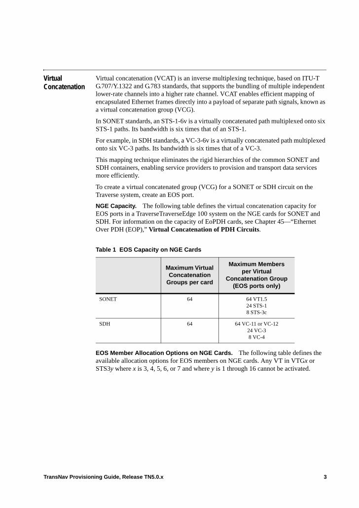
Virtual Concatenation
Virtual concatenation (VCAT) is an inverse multiplexing technique, based on ITU-T G.707/Y.1322 and G.783 standards, that supports the bundling of multiple independent lower-rate channels into a higher rate channel. VCAT enables efficient mapping of encapsulated Ethernet frames directly into a payload of separate path signals, known as a virtual concatenation group (VCG).
In SONET standards, an STS-1-6v is a virtually concatenated path multiplexed onto six STS-1 paths. Its bandwidth is six times that of an STS-1.
For example, in SDH standards, a VC-3-6v is a virtually concatenated path multiplexed onto six VC-3 paths. Its bandwidth is six times that of a VC-3.
This mapping technique eliminates the rigid hierarchies of the common SONET and SDH containers, enabling service providers to provision and transport data services more efficiently.
To create a virtual concatenated group (VCG) for a SONET or SDH circuit on the Traverse system, create an EOS port.
NGE Capacity. The following table defines the virtual concatenation capacity for EOS ports in a TraverseTraverseEdge 100 system on the NGE cards for SONET and SDH. For information on the capacity of EoPDH cards, see Chapter 45—“Ethernet Over PDH (EOP),” Virtual Concatenation of PDH Circuits.
EOS Member Allocation Options on NGE Cards. The following table defines the available allocation options for EOS members on NGE cards. Any VT in VTGx or STS3y where x is 3, 4, 5, 6, or 7 and where y is 1 through 16 cannot be activated.
Table 1 EOS Capacity on NGE Cards
Maximum Virtual Concatenation
Groups per card
Maximum Membersper Virtual
Concatenation Group (EOS ports only)
SONET 64 64 VT1.524 STS-18 STS-3c
SDH 64 64 VC-11 or VC-1224 VC-38 VC-4
TransNav Provisioning Guide, Release TN5.0.x 3
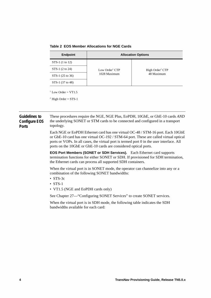
Guidelines to Configure EOS Ports
These procedures require the NGE, NGE Plus, EoPDH, 10GbE, or GbE-10 cards AND the underlying SONET or STM cards to be connected and configured in a transport topology.
Each NGE or EoPDH Ethernet card has one virtual OC-48 / STM-16 port. Each 10GbE or GbE-10 card has one virtual OC-192 / STM-64 port. These are called virtual optical ports or VOPs. In all cases, the virtual port is termed port 0 in the user interface. All ports on the 10GbE or GbE-10 cards are considered optical ports.
EOS Port Members (SONET or SDH Services). Each Ethernet card supports termination functions for either SONET or SDH. If provisioned for SDH termination, the Ethernet cards can process all supported SDH containers.
When the virtual port is in SONET mode, the operator can channelize into any or a combination of the following SONET bandwidths: • STS-3c• STS-1• VT1.5 (NGE and EoPDH cards only)
See Chapter 27—“Configuring SONET Services” to create SONET services.
When the virtual port is in SDH mode, the following table indicates the SDH bandwidths available for each card:
Table 2 EOS Member Allocations for NGE Cards
Endpoint Allocation Options
STS-1 (1 to 12)
Low Order1 CTP1028 Maximum
1 Low Order = VT1.5
High Order2 CTP48 Maximum
2 High Order = STS-1
STS-1 (2 to 24)
STS-1 (25 to 36)
STS-1 (37 to 48)
4 TransNav Provisioning Guide, Release TN5.0.x
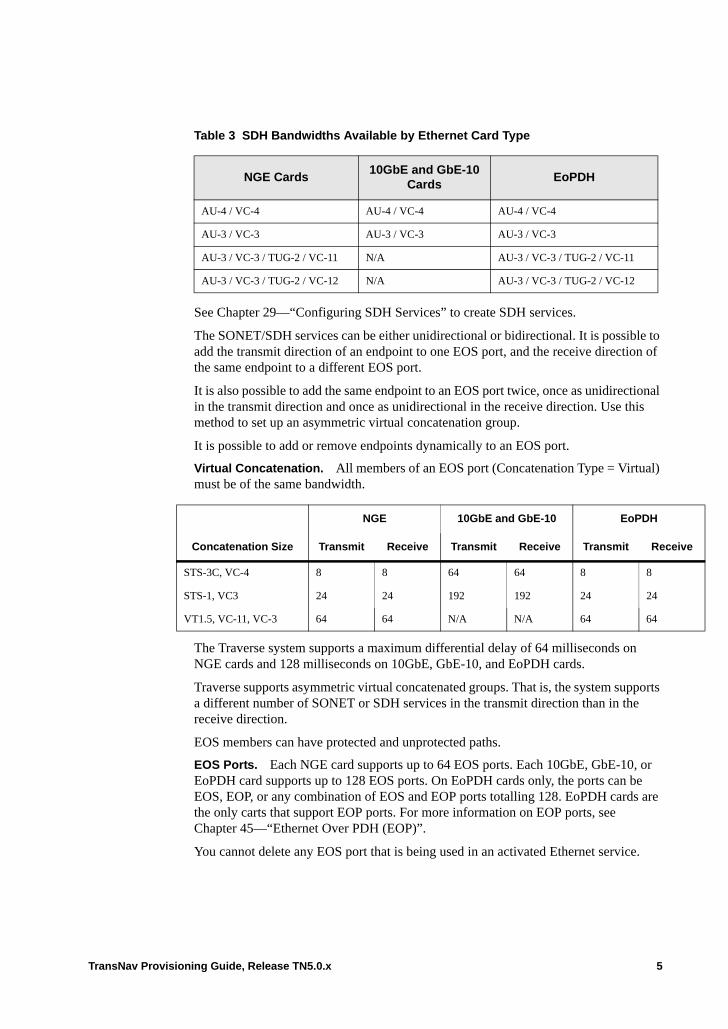
ive
Table 3 SDH Bandwidths Available by Ethernet Card Type
See Chapter 29—“Configuring SDH Services” to create SDH services.
The SONET/SDH services can be either unidirectional or bidirectional. It is possible to add the transmit direction of an endpoint to one EOS port, and the receive direction of the same endpoint to a different EOS port.
It is also possible to add the same endpoint to an EOS port twice, once as unidirectional in the transmit direction and once as unidirectional in the receive direction. Use this method to set up an asymmetric virtual concatenation group.
It is possible to add or remove endpoints dynamically to an EOS port.
Virtual Concatenation. All members of an EOS port (Concatenation Type = Virtual) must be of the same bandwidth.
The Traverse system supports a maximum differential delay of 64 milliseconds on NGE cards and 128 milliseconds on 10GbE, GbE-10, and EoPDH cards.
Traverse supports asymmetric virtual concatenated groups. That is, the system supports a different number of SONET or SDH services in the transmit direction than in the receive direction.
EOS members can have protected and unprotected paths.
EOS Ports. Each NGE card supports up to 64 EOS ports. Each 10GbE, GbE-10, or EoPDH card supports up to 128 EOS ports. On EoPDH cards only, the ports can be EOS, EOP, or any combination of EOS and EOP ports totalling 128. EoPDH cards are the only carts that support EOP ports. For more information on EOP ports, see Chapter 45—“Ethernet Over PDH (EOP)”.
You cannot delete any EOS port that is being used in an activated Ethernet service.
NGE Cards10GbE and GbE-10
CardsEoPDH
AU-4 / VC-4 AU-4 / VC-4 AU-4 / VC-4
AU-3 / VC-3 AU-3 / VC-3 AU-3 / VC-3
AU-3 / VC-3 / TUG-2 / VC-11 N/A AU-3 / VC-3 / TUG-2 / VC-11
AU-3 / VC-3 / TUG-2 / VC-12 N/A AU-3 / VC-3 / TUG-2 / VC-12
NGE 10GbE and GbE-10 EoPDH
Concatenation Size Transmit Receive Transmit Receive Transmit Rece
STS-3C, VC-4 8 8 64 64 8 8
STS-1, VC3 24 24 192 192 24 24
VT1.5, VC-11, VC-3 64 64 N/A N/A 64 64
TransNav Provisioning Guide, Release TN5.0.x 5

Additionally, for NGE cards only: • If you delete an EOS port that contains members, you must delete the EOS port from
both the local and remote NGE cards. • It is possible to add or remove members dynamically to an EOS port. Remove
members in both the local and the remote EOS ports. • Use a 1+1 EOS port protection group to protect Ethernet traffic leaving the Ethernet
card. For details, see Chapter 44—“EOS Port Protection.”
Before You Begin
Review the information in this topic before you configure EOS ports.
Table 4 EOS Port Requirements
Requirement Reference
Read the information in Chapter 1—“TN5.0.x Provisioning Overview”.
Ensure the requirements in Chapter 2—“Discover the Network,” Before You Start Provisioning Your Network are met.
Hardware
For Traverse nodes, the information in this section strictly pertains to the following Ethernet cards: NGE, NGE Plus, EoPDH, 10GbE and GbE-10.
For TE-100 nodes, the information pertains to all Ethernet services.
Traverse Hardware Guide
The correct ECMs are installed. Traverse Cabling and Cabling Specifications Guide , Chapter 16—“Ethernet (Electrical) Cabling Procedures”
The physical network is connected. Traverse Hardware Installation and Commissioning Guide
Software
Network is discovered. Chapter 2—“Discover the Network”
Timing is configured. Chapter 3—“Configure Network Timing”
Optical protection groups are configured for SDH networks.
Chapter 23—“Creating a 1+1 Optimized Protection Group”
If this card is part of a 1:1 Ethernet electrical protection group, the protection groups must be configured.
Configure the card or ports of the working card.
Chapter 12—“Configuring Ethernet Equipment”
Ethernet cards and interfaces are configured. Chapter 12—“Configuring Ethernet Equipment”
6 TransNav Provisioning Guide, Release TN5.0.x
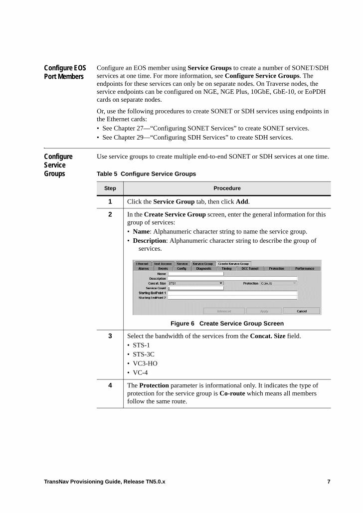
Configure EOS Port Members
Configure an EOS member using Service Groups to create a number of SONET/SDH services at one time. For more information, see Configure Service Groups. The endpoints for these services can only be on separate nodes. On Traverse nodes, the service endpoints can be configured on NGE, NGE Plus, 10GbE, GbE-10, or EoPDH cards on separate nodes.
Or, use the following procedures to create SONET or SDH services using endpoints in the Ethernet cards:• See Chapter 27—“Configuring SONET Services” to create SONET services.• See Chapter 29—“Configuring SDH Services” to create SDH services.
Configure Service Groups
Use service groups to create multiple end-to-end SONET or SDH services at one time.
Table 5 Configure Service Groups
Step Procedure
1 Click the Service Group tab, then click Add.
2 In the Create Service Group screen, enter the general information for this group of services:• Name: Alphanumeric character string to name the service group.• Description: Alphanumeric character string to describe the group of
services.
Figure 6 Create Service Group Screen
3 Select the bandwidth of the services from the Concat. Size field.• STS-1• STS-3C• VC3-HO• VC-4
4 The Protection parameter is informational only. It indicates the type of protection for the service group is Co-route which means all members follow the same route.
TransNav Provisioning Guide, Release TN5.0.x 7
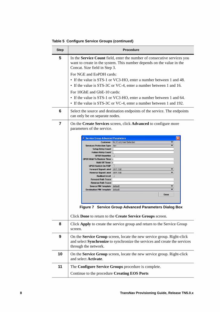
5 In the Service Count field, enter the number of consecutive services you want to create in the system. This number depends on the value in the Concat. Size field in Step 3.
For NGE and EoPDH cards:• If the value is STS-1 or VC3-HO, enter a number between 1 and 48.• If the value is STS-3C or VC-4, enter a number between 1 and 16.
For 10GbE and GbE-10 cards:• If the value is STS-1 or VC3-HO, enter a number between 1 and 64.• If the value is STS-3C or VC-4, enter a number between 1 and 192.
6 Select the source and destination endpoints of the service. The endpoints can only be on separate nodes.
7 On the Create Services screen, click Advanced to configure more parameters of the service.
Figure 7 Service Group Advanced Parameters Dialog Box
Click Done to return to the Create Service Groups screen.
8 Click Apply to create the service group and return to the Service Group screen.
9 On the Service Group screen, locate the new service group. Right-click and select Synchronize to synchronize the services and create the services through the network.
10 On the Service Group screen, locate the new service group. Right-click and select Activate.
11 The Configure Service Groups procedure is complete.
Continue to the procedure Creating EOS Ports
Table 5 Configure Service Groups (continued)
Step Procedure
8 TransNav Provisioning Guide, Release TN5.0.x
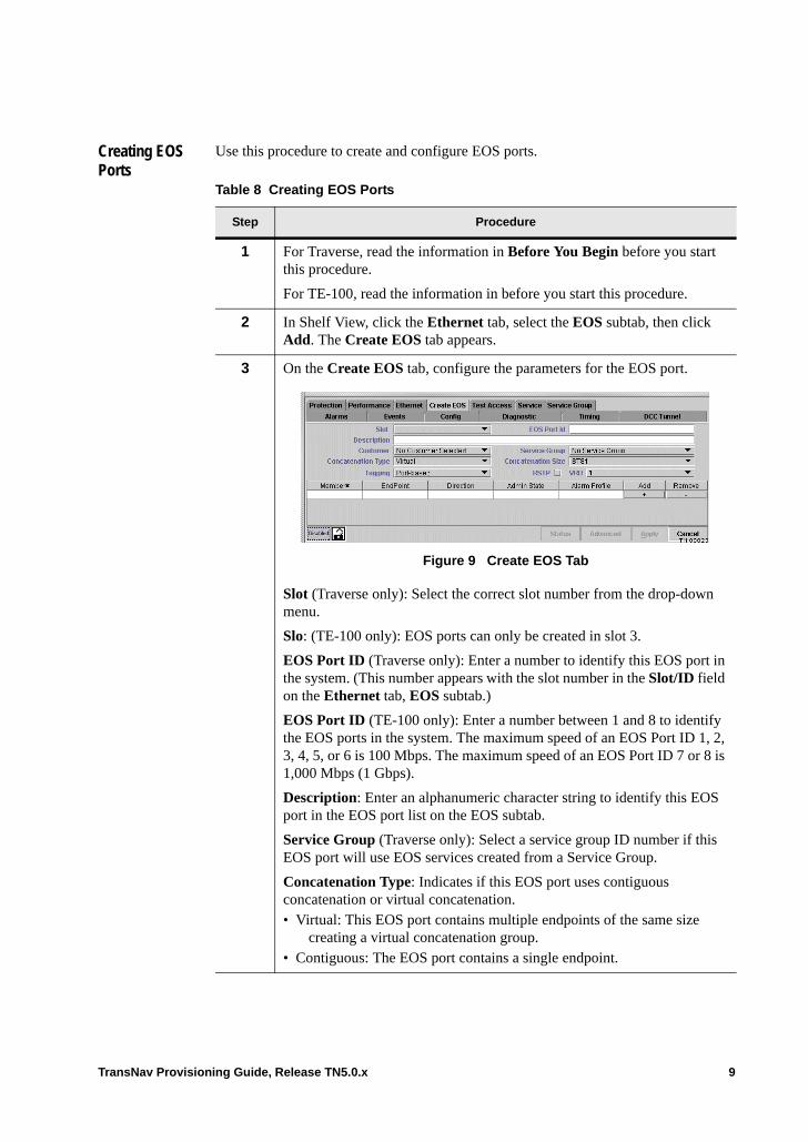
Creating EOS Ports
Use this procedure to create and configure EOS ports.
Table 8 Creating EOS Ports
Step Procedure
1 For Traverse, read the information in Before You Begin before you start this procedure.
For TE-100, read the information in before you start this procedure.
2 In Shelf View, click the Ethernet tab, select the EOS subtab, then click Add. The Create EOS tab appears.
3 On the Create EOS tab, configure the parameters for the EOS port.
Figure 9 Create EOS Tab
Slot (Traverse only): Select the correct slot number from the drop-down menu.
Slo: (TE-100 only): EOS ports can only be created in slot 3.
EOS Port ID (Traverse only): Enter a number to identify this EOS port in the system. (This number appears with the slot number in the Slot/ID field on the Ethernet tab, EOS subtab.)
EOS Port ID (TE-100 only): Enter a number between 1 and 8 to identify the EOS ports in the system. The maximum speed of an EOS Port ID 1, 2, 3, 4, 5, or 6 is 100 Mbps. The maximum speed of an EOS Port ID 7 or 8 is 1,000 Mbps (1 Gbps).
Description: Enter an alphanumeric character string to identify this EOS port in the EOS port list on the EOS subtab.
Service Group (Traverse only): Select a service group ID number if this EOS port will use EOS services created from a Service Group.
Concatenation Type: Indicates if this EOS port uses contiguous concatenation or virtual concatenation.• Virtual: This EOS port contains multiple endpoints of the same size
creating a virtual concatenation group. • Contiguous: The EOS port contains a single endpoint.
TransNav Provisioning Guide, Release TN5.0.x 9
Concatenation Size: Select the bandwidth of the transport paths that are members of this EOS port: • VT1.5 (NGE, NGE Plus, and EoPDH only)• STS-1• STS-3C• VC-11 (NGE, NGE Plus, and EoPDH only)• VC-12 (NGE, NGE Plus, and EoPDH only)• VC3-HO• VC-4
Tagging: Select one of the following tagging parameters: • Port-based: Every packet on this port is considered to belong to the
same service, regardless of whether or not the packet has a customer VLAN tag. Customer VLAN tags are not significant for service definition.
• Customer-tagged (Traverse only): Every packet on this port is assumed to have a VLAN tag that identifies its service in the customer network. This VLAN tag is termed the customer VLAN tag and is significant for Traverse Ethernet service definition. Customer-tagged ports use the customer VLAN tag, meaning the service provider can have multiple Ethernet streams sharing the same port, each identified by a separate customer VLAN ID.
• Service-tagged: Every packet on this port is assumed to have a service provider VLAN ID that identifies its Ethernet service within the service provider network. Service provider VLAN tags are used within the service provider network and are never used on customer-facing ports. The service provider VLAN tag optionally carries packet class of service and drop precedence information used within the service provider network and not conveyed to the end customer.
RSTP (Traverse only): Click the check box to enable RSTP (Rapid Spanning Tree Protocol).
Note: If you are setting up Virtual RSTP, you should first set up the Virtual RSTP Bridges (VRBs). See Chapter 9—“Rapid Spanning Tree Protocol,” for more information.
VRB (Traverse only): If you are setting up VRSTP and have already set up your VRBs, click this field and select the VRB number from the drop-down menu for this EOS port. Valid values are 1 through 20; default is 1.
Table 8 Creating EOS Ports (continued)
Step Procedure
10 TransNav Provisioning Guide, Release TN5.0.x
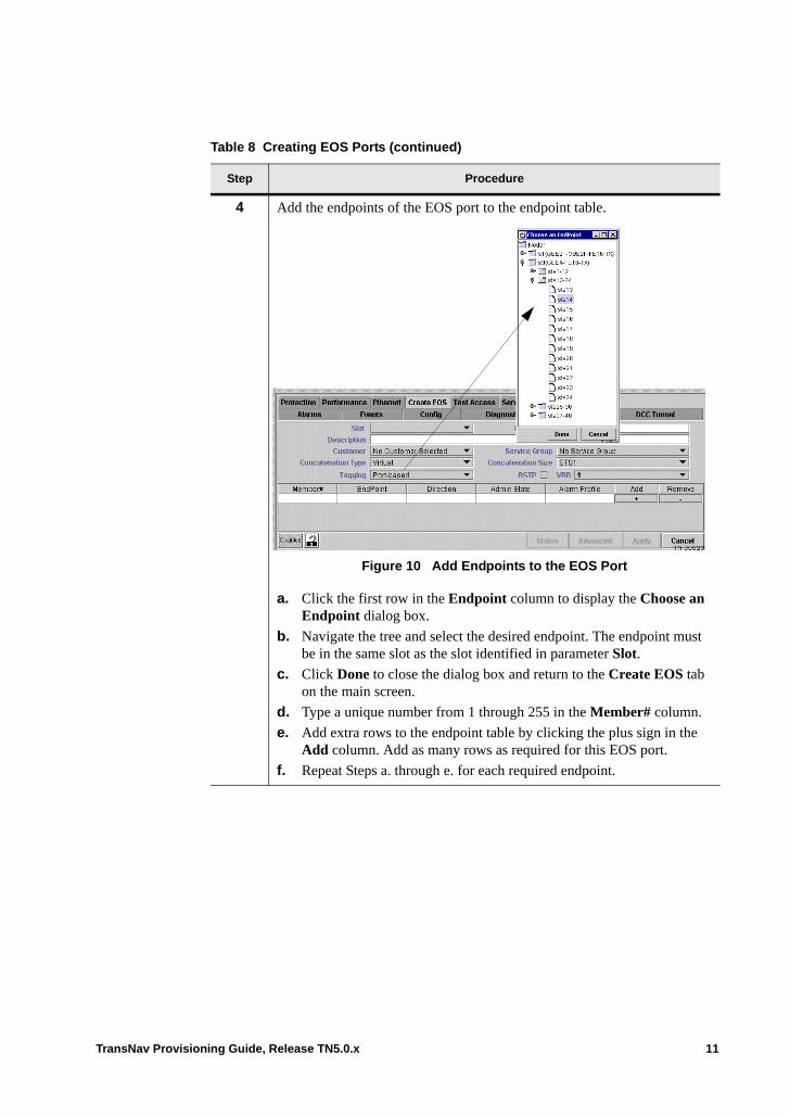
4 Add the endpoints of the EOS port to the endpoint table.
Figure 10 Add Endpoints to the EOS Port
a. Click the first row in the Endpoint column to display the Choose an Endpoint dialog box.
b. Navigate the tree and select the desired endpoint. The endpoint must be in the same slot as the slot identified in parameter Slot.
c. Click Done to close the dialog box and return to the Create EOS tab on the main screen.
d. Type a unique number from 1 through 255 in the Member# column.
e. Add extra rows to the endpoint table by clicking the plus sign in the Add column. Add as many rows as required for this EOS port.
f. Repeat Steps a. through e. for each required endpoint.
Table 8 Creating EOS Ports (continued)
Step Procedure
TransNav Provisioning Guide, Release TN5.0.x 11
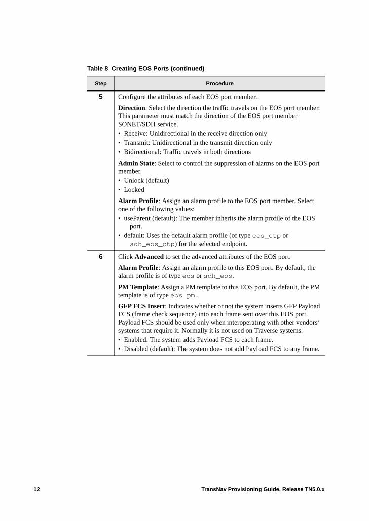
5 Configure the attributes of each EOS port member.
Direction: Select the direction the traffic travels on the EOS port member. This parameter must match the direction of the EOS port member SONET/SDH service. • Receive: Unidirectional in the receive direction only• Transmit: Unidirectional in the transmit direction only• Bidirectional: Traffic travels in both directions
Admin State: Select to control the suppression of alarms on the EOS port member.• Unlock (default)• Locked
Alarm Profile: Assign an alarm profile to the EOS port member. Select one of the following values:• useParent (default): The member inherits the alarm profile of the EOS
port. • default: Uses the default alarm profile (of type eos_ctp or
sdh_eos_ctp) for the selected endpoint.
6 Click Advanced to set the advanced attributes of the EOS port.
Alarm Profile: Assign an alarm profile to this EOS port. By default, the alarm profile is of type eos or sdh_eos.
PM Template: Assign a PM template to this EOS port. By default, the PM template is of type eos_pm.
GFP FCS Insert: Indicates whether or not the system inserts GFP Payload FCS (frame check sequence) into each frame sent over this EOS port. Payload FCS should be used only when interoperating with other vendors’ systems that require it. Normally it is not used on Traverse systems.• Enabled: The system adds Payload FCS to each frame.• Disabled (default): The system does not add Payload FCS to any frame.
Table 8 Creating EOS Ports (continued)
Step Procedure
12 TransNav Provisioning Guide, Release TN5.0.x

7 Insert Alternate VLAN Ethertype: For EOS ports 7 or 8 (1 Gbps) on TE-100. If this parameter is enabled, this EOS port will use the Alternate VLAN Ethertype value when a VLAN swap or add operation is performed on a packet being sent out this port.
On Traverse only, enable this parameter if one or more ports are connected to devices that require this alternate value. In addition, enable the Insert Alternate VLAN Ethertype parameter on those ports.
On NGE and NGE Plus cards, the alternate value is used in all VLAN tags in a packet.
On 10GbE or GbE-10 cards, the system distinguishes between inner (customer) and outer (service) tags. Inner tags must have 0x8100 Ethertype; outer tags must match the setting of this parameter. For example, if 0x9100 is selected then only service tags with 0x9100 will be recognized. If only one tag exists, it is the outer tag and statements made for service tag apply.
8 In the Queuing Policy parameter, specify how the queues are managed. Select one of the following values: • FIFO (default) (Traverse only): First-in, first-out. Select this queuing
policy to schedule all packets for transmission based on the FIFO algorithm. All traffic uses CoS1. Optionally, configure whether shaping should be employed using the FIFO Shaping Enable and the FIFO Shape Rate parameters. Go to Step 9.
• Priority: Select this queuing policy to schedule all packets for transmission based on strict priority, using three classes of service. There are three priorities: Highest priority traffic uses CoS1, medium priority traffic uses CoS2, and low priority traffic uses CoS3.
• WFQ (Traverse only): Weighted fair queuing. Select this queuing policy to guarantee a specific amount of the port’s bandwidth when there is congestion on the port. WFQ uses four classes of service and the guarantees are specified as weights. If the value in this parameter is WFQ, specify the weights in the four WFQ CoS weight {1 | 2 | 3 | 4} parameters. Go to Step 10.
• WFQ (TE-100 only): Weighted fair queuing. Select this queuing policy to guarantee a specific amount of the port’s bandwidth when there is congestion on the port. WFQ uses three classes of service and the guarantees are specified as weights. If the value in this parameter is WFQ, specify the weights in the three WFQ CoS weight {1 | 2 | 3} parameters. Go to Step 10.
Table 8 Creating EOS Ports (continued)
Step Procedure
TransNav Provisioning Guide, Release TN5.0.x 13
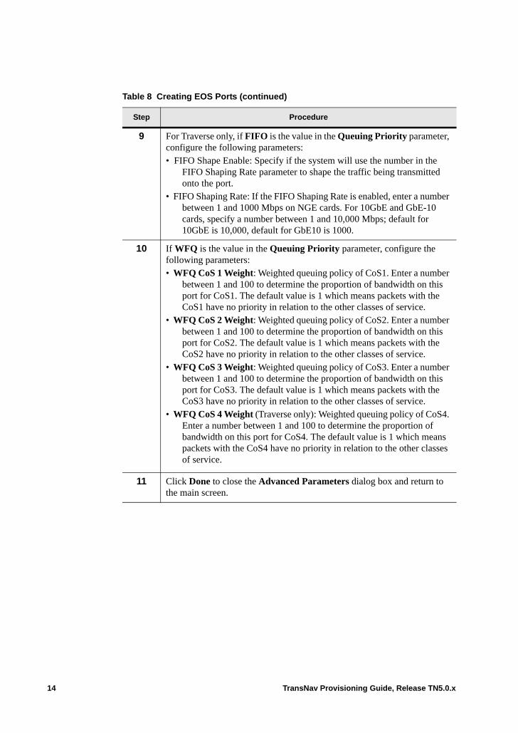
9 For Traverse only, if FIFO is the value in the Queuing Priority parameter, configure the following parameters:• FIFO Shape Enable: Specify if the system will use the number in the
FIFO Shaping Rate parameter to shape the traffic being transmitted onto the port.
• FIFO Shaping Rate: If the FIFO Shaping Rate is enabled, enter a number between 1 and 1000 Mbps on NGE cards. For 10GbE and GbE-10 cards, specify a number between 1 and 10,000 Mbps; default for 10GbE is 10,000, default for GbE10 is 1000.
10 If WFQ is the value in the Queuing Priority parameter, configure the following parameters:• WFQ CoS 1 Weight: Weighted queuing policy of CoS1. Enter a number
between 1 and 100 to determine the proportion of bandwidth on this port for CoS1. The default value is 1 which means packets with the CoS1 have no priority in relation to the other classes of service.
• WFQ CoS 2 Weight: Weighted queuing policy of CoS2. Enter a number between 1 and 100 to determine the proportion of bandwidth on this port for CoS2. The default value is 1 which means packets with the CoS2 have no priority in relation to the other classes of service.
• WFQ CoS 3 Weight: Weighted queuing policy of CoS3. Enter a number between 1 and 100 to determine the proportion of bandwidth on this port for CoS3. The default value is 1 which means packets with the CoS3 have no priority in relation to the other classes of service.
• WFQ CoS 4 Weight (Traverse only): Weighted queuing policy of CoS4. Enter a number between 1 and 100 to determine the proportion of bandwidth on this port for CoS4. The default value is 1 which means packets with the CoS4 have no priority in relation to the other classes of service.
11 Click Done to close the Advanced Parameters dialog box and return to the main screen.
Table 8 Creating EOS Ports (continued)
Step Procedure
14 TransNav Provisioning Guide, Release TN5.0.x
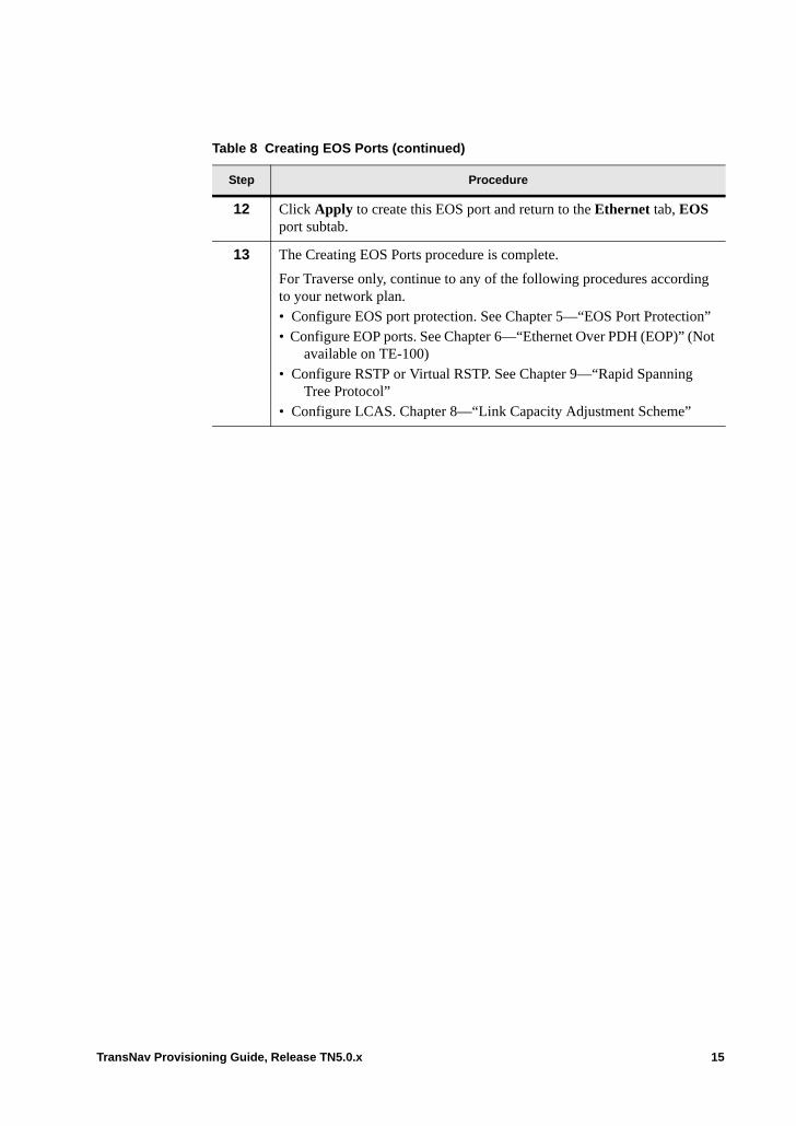
12 Click Apply to create this EOS port and return to the Ethernet tab, EOS port subtab.
13 The Creating EOS Ports procedure is complete.
For Traverse only, continue to any of the following procedures according to your network plan. • Configure EOS port protection. See Chapter 5—“EOS Port Protection”• Configure EOP ports. See Chapter 6—“Ethernet Over PDH (EOP)” (Not
available on TE-100)• Configure RSTP or Virtual RSTP. See Chapter 9—“Rapid Spanning
Tree Protocol”• Configure LCAS. Chapter 8—“Link Capacity Adjustment Scheme”
Table 8 Creating EOS Ports (continued)
Step Procedure
TransNav Provisioning Guide, Release TN5.0.x 15
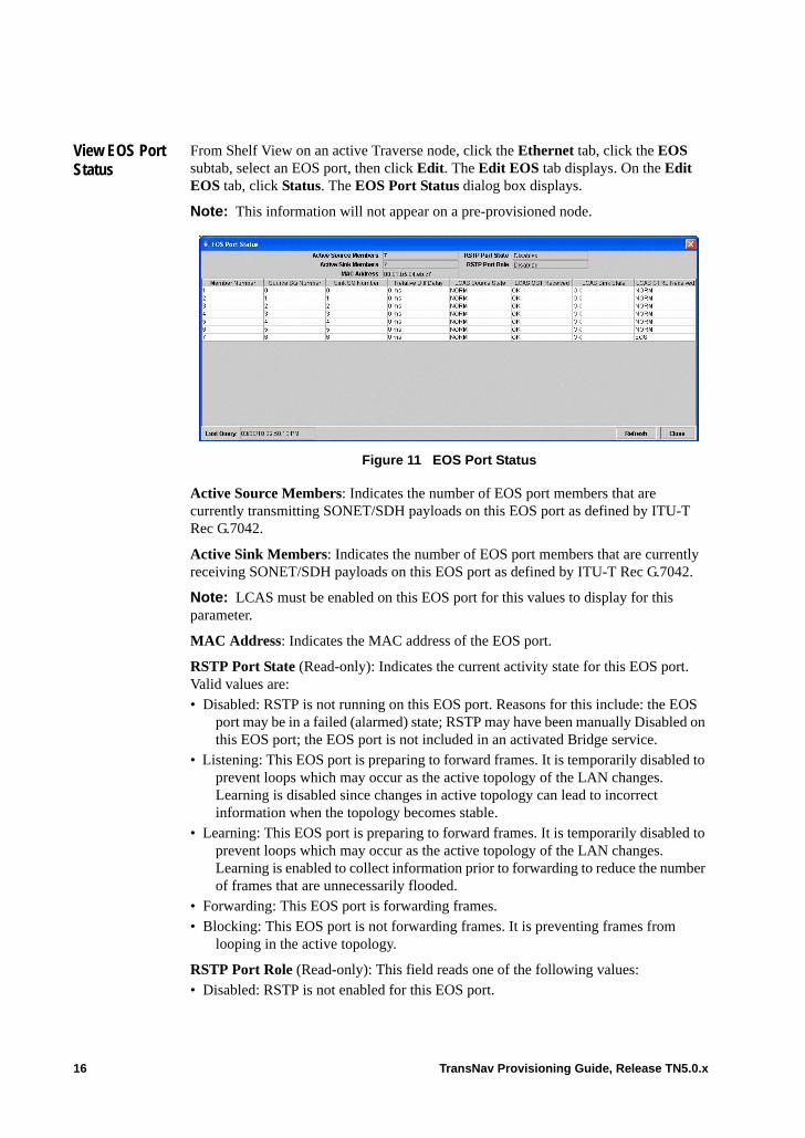
View EOS Port Status
From Shelf View on an active Traverse node, click the Ethernet tab, click the EOS subtab, select an EOS port, then click Edit. The Edit EOS tab displays. On the Edit EOS tab, click Status. The EOS Port Status dialog box displays.
Note: This information will not appear on a pre-provisioned node.
Figure 11 EOS Port Status
Active Source Members: Indicates the number of EOS port members that are currently transmitting SONET/SDH payloads on this EOS port as defined by ITU-T Rec G.7042.
Active Sink Members: Indicates the number of EOS port members that are currently receiving SONET/SDH payloads on this EOS port as defined by ITU-T Rec G.7042.
Note: LCAS must be enabled on this EOS port for this values to display for this parameter.
MAC Address: Indicates the MAC address of the EOS port.
RSTP Port State (Read-only): Indicates the current activity state for this EOS port. Valid values are:• Disabled: RSTP is not running on this EOS port. Reasons for this include: the EOS
port may be in a failed (alarmed) state; RSTP may have been manually Disabled on this EOS port; the EOS port is not included in an activated Bridge service.
• Listening: This EOS port is preparing to forward frames. It is temporarily disabled to prevent loops which may occur as the active topology of the LAN changes. Learning is disabled since changes in active topology can lead to incorrect information when the topology becomes stable.
• Learning: This EOS port is preparing to forward frames. It is temporarily disabled to prevent loops which may occur as the active topology of the LAN changes. Learning is enabled to collect information prior to forwarding to reduce the number of frames that are unnecessarily flooded.
• Forwarding: This EOS port is forwarding frames.• Blocking: This EOS port is not forwarding frames. It is preventing frames from
looping in the active topology.
RSTP Port Role (Read-only): This field reads one of the following values: • Disabled: RSTP is not enabled for this EOS port.
16 TransNav Provisioning Guide, Release TN5.0.x
• Root: This EOS port is closest to the root bridge in terms of path cost. This EOS port also forwards Ethernet frames.
• Designated: This EOS port forwards Ethernet frames. • Alternate: This EOS port is blocked but can quickly become forwarding ports when
the topology is reconfigured.
Member Number: Indicates the provisioned EOS port member number.
Source SQ Number: Indicates the sequence identifier (SQ) of the transmitting EOS port member.
Source Sink Number: Indicates the member number of the receiving member for this transmission.
Relative Diff Delay (Traverse): Relative differential delay. The amount of delay in milliseconds between arrival of a signal on the earliest member of the EOS port, and arrival of the correlated signal on this member, regardless of whether LCAS is enabled. Maximum possible delays are 64ms for NGE and NGE Plus cards and 128ms for 10GbE and GbE-10 cards.
Rel Delay (TE-100): Relative differential delay. The amount of delay in milliseconds between arrival of a signal on the earliest member of the EOS port, and arrival of the correlated signal on this member, regardless of whether LCAS is enabled.
LCAS Source State: (LCAS-enabled EOS ports only): Indicates the current LCAS source state of this EOS port member. Valid values are:• IDLE: Member is not part of an LCAS VCG• ADD: Member is joining an LCAS VCG due to management action• NORM: Member has joined an LCAS VCG and is transmitting bytes• DNU: Member has joined an LCAS VCG but is not transmitting bytes because the
far end sink has indicated that it is unable to receive from this member• REMOVE: Member is being removed from an LCAS VCG due to management
action
LCAS MST Received (Traverse only): LCAS Member Status received. (LCAS-enabled EOS ports only): Indicates the current LCAS Member Status of this EOS port member received from the far-end sink. Valid values are:• OK: Member has joined an LCAS VCG and is able to receive bytes or is currently
receiving bytes• FAIL: Member is unable to join the indicated LCAS VCG. The path may be down or
the path is up and has not yet been added to the VCG by LCAS. Check the path status and the EOS member LCAS status at the destination.
• INVALID: The MST information received from the far-end is not valid. This should be a transient condition only.
LCAS Sink State: Indicates the far-end LCAS sink state as interpreted by the near-end source based on the received Member Status. Valid values are:• IDLE: Member is not part of an LCAS VCG• OK: Member has joined an LCAS VCG and is able to receive bytes or is currently
receiving bytes
TransNav Provisioning Guide, Release TN5.0.x 17
• FAIL: Member is unable to join the indicated LCAS VCG. The path may be down or the path is up and has not yet been added to the VCG by LCAS. Check the path status and the EOS member LCAS status at the destination.
LCAS CTRL Received (Traverse only): The LCAS CTRL word being sent by the far-end source to the near-end sink. Valid values are • FIXED: Indicates this EOS port member uses fixed bandwidth (non-LCAS mode)• ADD: Member is joining an LCAS VCG due to management action• NORM: Member has joined an LCAS VCG and is transmitting bytes• EOS: Member has joined an LCAS VCG and is transmitting bytes. This is the last
member in the VCG sequence (End Of Sequence)• IDLE: Member is not in an LCAS VCG or is about to be removed.• DNU: Member has joined an LCAS VCG but is not transmitting bytes. This is
because the near-end sink is unable to receive bytes (is sending MST = FAIL to far-end source)
• INVALID: The near-end sink is not receiving a valid LCAS CTRL word
Last Query (Read-only): The date and time of the last query on the status of the EOS port.
18 TransNav Provisioning Guide, Release TN5.0.x
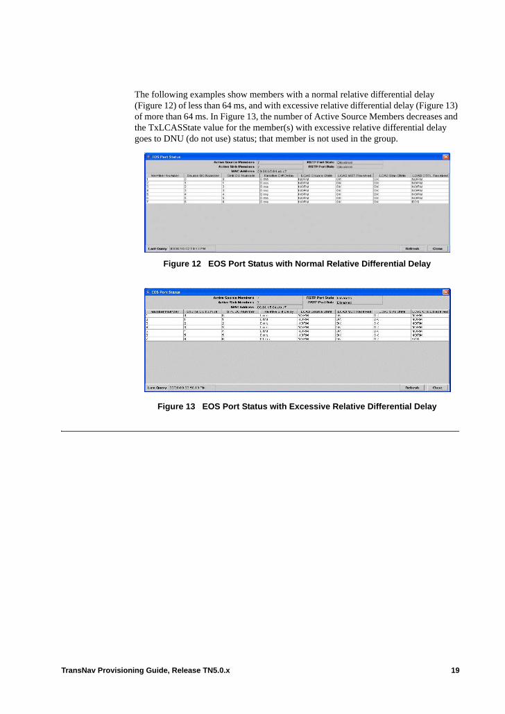
The following examples show members with a normal relative differential delay (Figure 12) of less than 64 ms, and with excessive relative differential delay (Figure 13) of more than 64 ms. In Figure 13, the number of Active Source Members decreases and the TxLCASState value for the member(s) with excessive relative differential delay goes to DNU (do not use) status; that member is not used in the group.
Figure 12 EOS Port Status with Normal Relative Differential Delay
Figure 13 EOS Port Status with Excessive Relative Differential Delay
TransNav Provisioning Guide, Release TN5.0.x 19

20 TransNav Provisioning Guide, Release TN5.0.x
Chapter 44 EOS Port Protection
Introduction This chapter contains the following topics:• Example of EOS Port Protection• Guidelines to Configure EOS Port Protection• Before You Begin• Create a 1+1 EOS Port Protection Group
TransNav Provisioning Guide, Release TN5.0.x 1
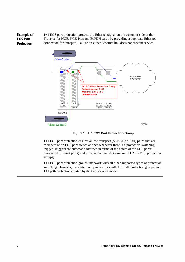
Example of EOS Port Protection
1+1 EOS port protection protects the Ethernet signal on the customer side of the Traverse for NGE, NGE Plus and EoPDH cards by providing a duplicate Ethernet connection for transport. Failure on either Ethernet link does not prevent service.
Figure 1 1+1 EOS Port Protection Group
1+1 EOS port protection ensures all the transport (SONET or SDH) paths that are members of an EOS port switch at once whenever there is a protection-switching trigger. Triggers are automatic (defined in terms of the health of the EOS ports’ associated Ethernet ports) and external commands (same as 1+1 APS/MSP protection groups).
1+1 EOS port protection groups interwork with all other supported types of protection switching. However, the system only interworks with 1+1 path protection groups not 1+1 path protection created by the two services model.
Node 1
GBE/FETXSlot 1
.
.
.
.
.
.
GBE/FETXSlot 2
.
.
.
.
.
.
Slot 11
W
OC192/STM64
Slot 13
E
OC192/STM64
Video Codec 1
PWR
OK
WIC0ACT/CH0
ACT/CH1
WIC0ACT/CH0
ACT/CH1
ETHACT
COL
Video Codec 2
OC-192/STM-64UPSR/SNCP
PWR
OK
WIC0ACT/CH0
ACT/CH1
WIC0ACT/CH0
ACT/CH1
ETHACT
COL
1+1 EOS Port Protection GroupProtecting: slot 1-id1Working: slot 2-id 1Unidirectional
TR 00035
2 TransNav Provisioning Guide, Release TN5.0.x
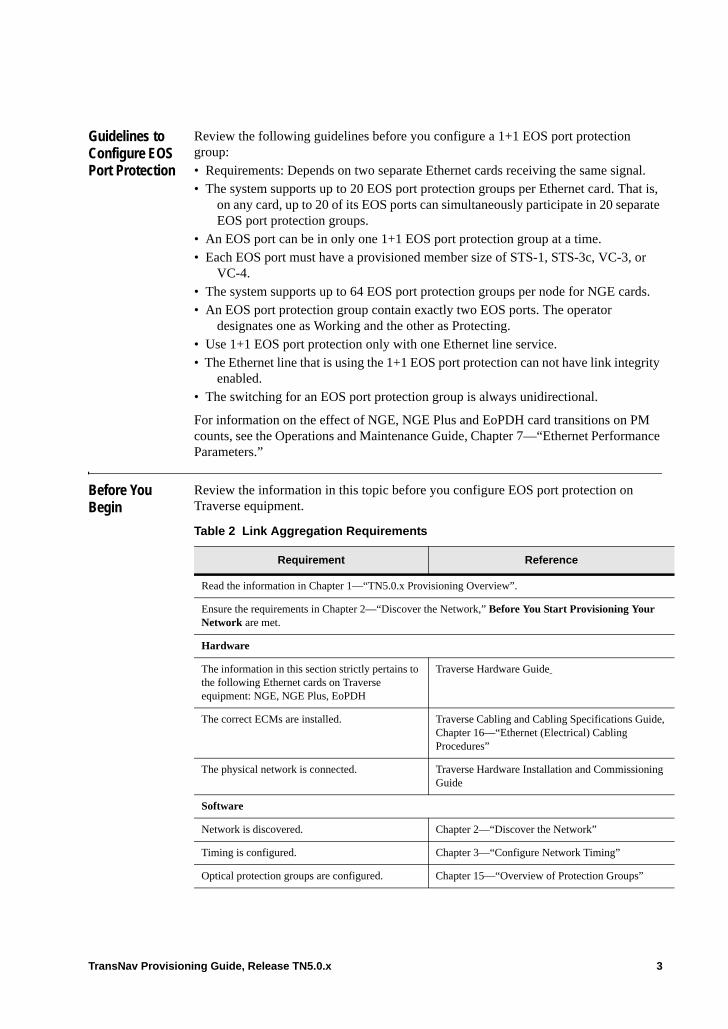
Guidelines to Configure EOS Port Protection
Review the following guidelines before you configure a 1+1 EOS port protection group:• Requirements: Depends on two separate Ethernet cards receiving the same signal. • The system supports up to 20 EOS port protection groups per Ethernet card. That is,
on any card, up to 20 of its EOS ports can simultaneously participate in 20 separate EOS port protection groups.
• An EOS port can be in only one 1+1 EOS port protection group at a time.• Each EOS port must have a provisioned member size of STS-1, STS-3c, VC-3, or
VC-4. • The system supports up to 64 EOS port protection groups per node for NGE cards. • An EOS port protection group contain exactly two EOS ports. The operator
designates one as Working and the other as Protecting.• Use 1+1 EOS port protection only with one Ethernet line service. • The Ethernet line that is using the 1+1 EOS port protection can not have link integrity
enabled. • The switching for an EOS port protection group is always unidirectional.
For information on the effect of NGE, NGE Plus and EoPDH card transitions on PM counts, see the Operations and Maintenance Guide, Chapter 7—“Ethernet Performance Parameters.”
Before You Begin
Review the information in this topic before you configure EOS port protection on Traverse equipment.
Table 2 Link Aggregation Requirements
Requirement Reference
Read the information in Chapter 1—“TN5.0.x Provisioning Overview”.
Ensure the requirements in Chapter 2—“Discover the Network,” Before You Start Provisioning Your Network are met.
Hardware
The information in this section strictly pertains to the following Ethernet cards on Traverse equipment: NGE, NGE Plus, EoPDH
Traverse Hardware Guide
The correct ECMs are installed. Traverse Cabling and Cabling Specifications Guide, Chapter 16—“Ethernet (Electrical) Cabling Procedures”
The physical network is connected. Traverse Hardware Installation and Commissioning Guide
Software
Network is discovered. Chapter 2—“Discover the Network”
Timing is configured. Chapter 3—“Configure Network Timing”
Optical protection groups are configured. Chapter 15—“Overview of Protection Groups”
TransNav Provisioning Guide, Release TN5.0.x 3
If this card is part of a 1:1 Ethernet electrical protection group, the protection groups must be configured.
Chapter 18—“Creating Equipment Protection Groups”
Ethernet cards and interfaces are configured. Chapter 18—“Creating Equipment Protection Groups”
EOS ports are correctly configured. Chapter 43—“Ethernet Over SONET/SDH (EOS)”
Table 2 Link Aggregation Requirements (continued)
Requirement Reference
4 TransNav Provisioning Guide, Release TN5.0.x

Create a 1+1 EOS Port Protection Group
Use this procedure to create a 1+1 EOS port protection group.
Table 3 Create a 1+1 EOS Port Protection Group
Step Procedure
1 Review the information in Before You Begin before you start this procedure.
2 In Shelf View, add a 1+1 EOS protection group.
Figure 4 Select 1+1 EOS
a. Click the Protection tab to display the Protection Groups screen.
b. From the New list, select 1+1 EOS.
c. Click Add to display the Create EOS tab.
3 On the 1+1 EOS Protection Group screen, enter the attributes of the protection group.
Figure 5 Add 1+1 Protection Group Screen
In the Name field, enter the name of the node (maximum 43 characters). Use alphanumeric characters only. Do not use punctuation or any special characters in this field.
4 Set the reversion options:• Select the Revertive checkbox to switch traffic back to the working card
when the working port has recovered from the original failure condition or the external command is cleared.
• In the WTR Time field, set a time in minutes that the system will wait after a protection switch before switching back to the working port.Enter a number between 1 and 60; default is 5.
3a
3b3c
45
6
TransNav Provisioning Guide, Release TN5.0.x 5
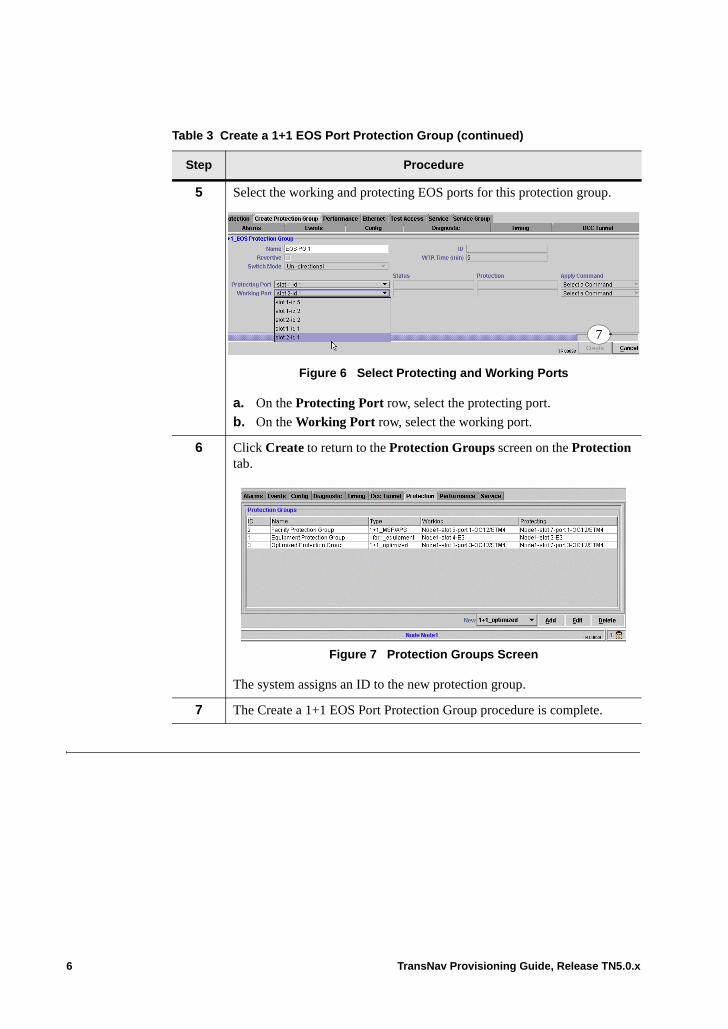
5 Select the working and protecting EOS ports for this protection group.
Figure 6 Select Protecting and Working Ports
a. On the Protecting Port row, select the protecting port.
b. On the Working Port row, select the working port.
6 Click Create to return to the Protection Groups screen on the Protection tab.
Figure 7 Protection Groups Screen
The system assigns an ID to the new protection group.
7 The Create a 1+1 EOS Port Protection Group procedure is complete.
Table 3 Create a 1+1 EOS Port Protection Group (continued)
Step Procedure
7
6 TransNav Provisioning Guide, Release TN5.0.x
Chapter 45 Ethernet Over PDH (EOP)
Introduction In a Traverse system, EoPDH is an access technology used to bring Ethernet frames to a Traverse node for switching and forwarding to nodes within the system on a transport network. Most EoPDH applications will use a combination of EOS and EOP (Ethernet over PDH) ports. The PDH circuits containing Ethernet frames arrive at an EoPDH card where they are extracted from the EoPDH link. The extracted frames are then forwarded within the Traverse network over an EOS link which acts as a network-to-network interface.
The information in this chapter strictly pertains to the Traverse Ethernet over PDH (EoPDH) cards (GBE4-FE16-TX-EoPDH and GBE2T-GBE2F-FE16-TX-EoPDH). It contains the following topics:• Ethernet over PDH (EOP) Requirements• Virtual Concatenation of PDH Circuits • Guidelines to Configure EOS and EOP Ports on EOPDH Cards• Before You Begin• Creating EOP Ports
Transmission times on EOP ports is slower than for other Ethernet links. For more information, see Chapter 52—“Ethernet Traffic Management,” Managing Traffic on EOP Ports.
Ethernet over PDH (EOP) Requirements
On EoPDH cards, in addition to SONET or SDH connections, traffic can also travel over PDH connections called EOP ports. However, because they are used for access not transport, EOP ports are more like Ethernet ports than EOS ports. For more information on EOS ports, refer to Chapter 43—“Ethernet Over SONET/SDH (EOS)” in this section.
Physical PDH ports have Administrative and Operational states. EOP port members, like EOS port members, have only an Administrative state.
Creating Ethernet over PDH (EOP) connections requires three components and can only be created on EoPDH cards:• EOP ports: On the Traverse system, an EOP port is a port-like abstraction
representing the adaptation point between Ethernet and PDH. This EOP port can be thought of as an Ethernet WAN interface, compared to physical Ethernet ports which are Ethernet LAN interfaces.
TransNav Provisioning Guide, Release TN5.0.x 1
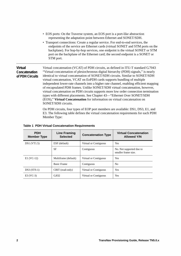
• EOS ports: On the Traverse system, an EOS port is a port-like abstraction representing the adaptation point between Ethernet and SONET/SDH.
• Transport connections: Create a regular service. For end-to-end services, the endpoints of the service are Ethernet cards (virtual SONET and STM ports on the backplane). For hop-by-hop services, one endpoint is the virtual SONET or STM port on the backplane of the Ethernet card; the second endpoint is a SONET or STM port.
Virtual Concatenation of PDH Circuits
Virtual concatenation (VCAT) of PDH circuits, as defined in ITU-T standard G.7043 “Virtual concatenation of plesiochronous digital hierarchy (PDH) signals,” is nearly identical to virtual concatenation of SONET/SDH circuits. Similar to SONET/SDH virtual concatenation, VCAT on EoPDH cards supports bundling of multiple independent lower-rate channels into a higher rate channel, enabling efficient mapping of encapsulated PDH frames. Unlike SONET/SDH virtual concatenation, however, virtual concatenation on PDH circuits supports more low order connection termination types with different placements. See Chapter 43—“Ethernet Over SONET/SDH (EOS),” Virtual Concatenation for information on virtual concatenation on SONET/SDH circuits.
On PDH circuits, four types of EOP port members are available: DS1, DS3, E1, and E3. The following table defines the virtual concatenation requirements for each PDH Member Type:
Table 1 PDH Virtual Concatenation Requirements
PDH Member Type
Line Framing Selected
Concatenation TypeVirtual Concatenation
Allowed Y/N
DS1 (VT1.5) ESF (default) Virtual or Contiguous Yes
SF Contiguous No. Not supported due to smaller frame size.
E1 (VC-12) Multiframe (default) Virtual or Contiguous Yes
Basic Frame Contiguous No
DS3 (STS-1) CBIT (read-only) Virtual or Contiguous Yes
E3 (VC-3) G.832 Virtual or Contiguous Yes
2 TransNav Provisioning Guide, Release TN5.0.x
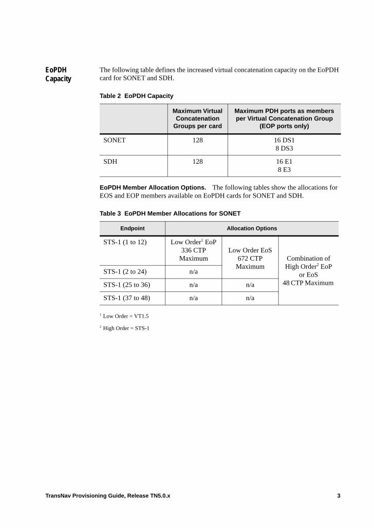
EoPDH Capacity
The following table defines the increased virtual concatenation capacity on the EoPDH card for SONET and SDH.
EoPDH Member Allocation Options. The following tables show the allocations for EOS and EOP members available on EoPDH cards for SONET and SDH.
Table 2 EoPDH Capacity
Maximum Virtual Concatenation
Groups per card
Maximum PDH ports as membersper Virtual Concatenation Group
(EOP ports only)
SONET 128 16 DS1 8 DS3
SDH 128 16 E18 E3
Table 3 EoPDH Member Allocations for SONET
Endpoint Allocation Options
STS-1 (1 to 12) Low Order1 EoP 336 CTP
Maximum
1 Low Order = VT1.5
Low Order EoS672 CTP
MaximumCombination of High Order2 EoP
or EoS48 CTP Maximum
2 High Order = STS-1
STS-1 (2 to 24) n/a
STS-1 (25 to 36) n/a n/a
STS-1 (37 to 48) n/a n/a
TransNav Provisioning Guide, Release TN5.0.x 3
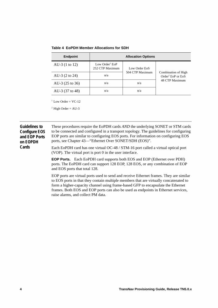
Guidelines to Configure EOS and EOP Ports on EOPDH Cards
These procedures require the EoPDH cards AND the underlying SONET or STM cards to be connected and configured in a transport topology. The guidelines for configuring EOP ports are similar to configuring EOS ports. For information on configuring EOS ports, see Chapter 43—“Ethernet Over SONET/SDH (EOS)”.
Each EoPDH card has one virtual OC-48 / STM-16 port called a virtual optical port (VOP). The virtual port is port 0 in the user interface.
EOP Ports. Each EoPDH card supports both EOS and EOP (Ethernet over PDH) ports. The EoPDH card can support 128 EOP, 128 EOS, or any combination of EOP and EOS ports that total 128.
EOP ports are virtual ports used to send and receive Ethernet frames. They are similar to EOS ports in that they contain multiple members that are virtually concatenated to form a higher-capacity channel using frame-based GFP to encapsulate the Ethernet frames. Both EOS and EOP ports can also be used as endpoints in Ethernet services, raise alarms, and collect PM data.
Table 4 EoPDH Member Allocations for SDH
Endpoint Allocation Options
AU-3 (1 to 12) Low Order1 EoP 252 CTP Maximum
1 Low Order = VC-12
Low Order EoS504 CTP Maximum Combination of High
Order2 EoP or EoS48 CTP Maximum
2 High Order = AU-3
AU-3 (2 to 24) n/a
AU-3 (25 to 36) n/a n/a
AU-3 (37 to 48) n/a n/a
4 TransNav Provisioning Guide, Release TN5.0.x

EOP Port Members (SONET or SDH Services). Each Ethernet card supports termination functions for either SONET or SDH, but not both. If provisioned for SDH termination, the Ethernet cards can terminate either VC-11 or VC-12, but not both at the same time. However, VC-11 and VC-12 can both coexist with VC-3. The following table describes the termination points and maximum connection termination points for each combination of port type and bandwidth.
Note: On EoPDH cards, low order connection termination points can reside only in the first 24 STSs or VC-3s of the card’s VOP.
On the EoPDH card’s OC-48 VOP, operators can provision the VT1.5 connection termination points in STS 1 through 12. Within those 12 STS’s, the operator can provision up to a total of 336 VT1.5 connection termination points.
When the EoPDH virtual port is in SDH mode, and the LO Mapping is VC-11, the operator can provision VC-11 connection termination points only in the 12 VC-3s contained in the first 12 AU-3s in the card’s STM-16 VOP. Within those 12 VC-3s, the operator can provision up to a total of 672 VC-11 connection termination points.
When the EoPDH virtual port is in SDH mode, and the LO Mapping is VC-12, the operator can provision VC-12 connection termination points only in the 12 VC-3s contained in the first 12 AU-3s in the card’s STM-16 VOP. Within those 12 VC-3s, the operator can provision up to a total of 504 VC-11 connection termination points.
The remaining SONET bandwidth (STS / VTG / VT) and SDH bandwidth (AUG / VC-3 / TUG-2 / VC) are available for provisioning high order connection termination points, as long as they do not exceed the virtual port limits.
Table 5 EOS and EOP Bandwidth and Termination Requirements
Port Type BandwidthSONET(STS)
Termination Points
SDHTermination Points1 Maximum CTPs
EOP DS12 1 through 12 Not supported 336
E1 Not supported 1 through 12 252
EOS VC-11 Not applicable 1 through 24 672
VC-12 Not applicable 1 through 24 504
VT1.5 1 through 24 Not applicable 672
EOP DS3 1 through 48 Not supported 48
E3 Not supported 1 through 48 48
EOS STS 1 through 48 1 through 48 48
VC3 Not applicable 1 through 48 48
VC4 Not applicable 1 through 16 16
1 All SDH Termination Points are VC3 except EOS VC4 which is AU4.
2 EoPDH supports only B8ZS line coding on DS1 members.
TransNav Provisioning Guide, Release TN5.0.x 5
The SONET and SDH services on EoPDH cards are bidirectional only.
On EoPDH cards and ports, operators can cross-connect between the following service types when the Ethernet card VOP is the source, the destination, or the source and destination:• Ethernet card VOP • HO (STS-3c, STS-1, VC-4, VC-3) or LO (VT1.5, VC-12, VC-11) CTPs on OC-N /
STM-N cards,DS3 / EC-1 Transmux cards (EC-1 ports only), or Ethernet card VOP.
• VC12 service to E1 inside DS3 inside VC3 • Optical Transmux
For additional information on the Ethernet services available on EoPDH cards, see Chapter 27—“Configuring SONET Services” and Chapter 29—“Configuring SDH Services.”
It is possible to add or remove endpoints dynamically to an EOP port.
Any EOP port being used in an activated Ethernet service cannot be deleted.
Virtual Concatenation. All members of a virtual EOP port must be of the same bandwidth. The EOP PDH Member Type defines the EOP port members as DS1 or DS3 for SONET, and E1 or E3 for SDH. DS1 and E1 PDH Member Types can transmit and receive up to 16 source members, while DS3 and E3 PDH Member Types can transmit and receive up to 8 source members.
The system supports a maximum differential delay of 128 milliseconds on EoPDH cards.
The Traverse supports asymmetric virtual concatenated groups. That is, the system supports a different number of SONET or SDH services in the transmit direction than in the receive direction. If a virtually concatenated group on an EoPDH card is provisioned LCAS Enabled at the transmit end but the receive end is not using LCAS, the system will produce a LCAS Inactive alarm as specified in ITU-T standard G.806, sections 10.1.1.1 and 10.1.1.2.
The system supports a mix of protected and unprotected members in the same virtually concatenated group.
An operator can dynamically add or remove protection for an EOP port member.
6 TransNav Provisioning Guide, Release TN5.0.x
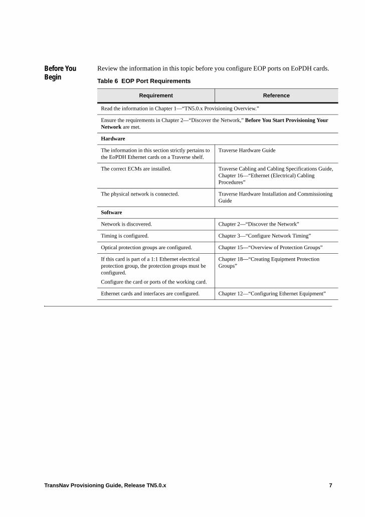
Before You Begin
Review the information in this topic before you configure EOP ports on EoPDH cards.
Table 6 EOP Port Requirements
Requirement Reference
Read the information in Chapter 1—“TN5.0.x Provisioning Overview.”
Ensure the requirements in Chapter 2—“Discover the Network,” Before You Start Provisioning Your Network are met.
Hardware
The information in this section strictly pertains to the EoPDH Ethernet cards on a Traverse shelf.
Traverse Hardware Guide
The correct ECMs are installed. Traverse Cabling and Cabling Specifications Guide, Chapter 16—“Ethernet (Electrical) Cabling Procedures”
The physical network is connected. Traverse Hardware Installation and Commissioning Guide
Software
Network is discovered. Chapter 2—“Discover the Network”
Timing is configured. Chapter 3—“Configure Network Timing”
Optical protection groups are configured. Chapter 15—“Overview of Protection Groups”
If this card is part of a 1:1 Ethernet electrical protection group, the protection groups must be configured.
Configure the card or ports of the working card.
Chapter 18—“Creating Equipment Protection Groups”
Ethernet cards and interfaces are configured. Chapter 12—“Configuring Ethernet Equipment”
TransNav Provisioning Guide, Release TN5.0.x 7
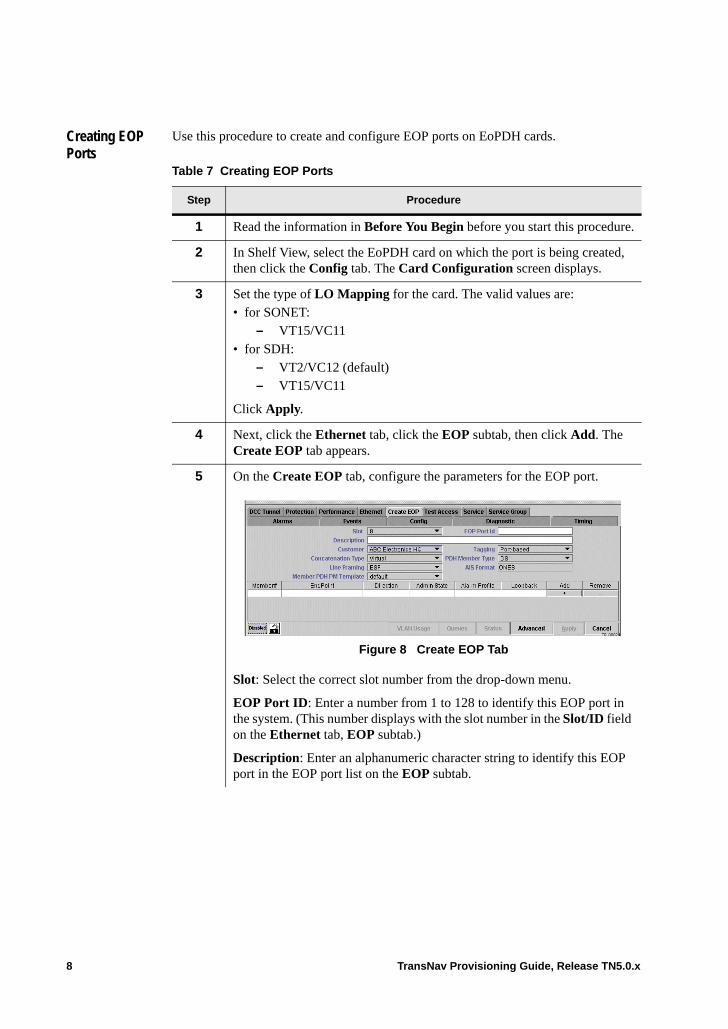
Creating EOP Ports
Use this procedure to create and configure EOP ports on EoPDH cards.
Table 7 Creating EOP Ports
Step Procedure
1 Read the information in Before You Begin before you start this procedure.
2 In Shelf View, select the EoPDH card on which the port is being created, then click the Config tab. The Card Configuration screen displays.
3 Set the type of LO Mapping for the card. The valid values are:• for SONET:
– VT15/VC11 • for SDH:
– VT2/VC12 (default)– VT15/VC11
Click Apply.
4 Next, click the Ethernet tab, click the EOP subtab, then click Add. The Create EOP tab appears.
5 On the Create EOP tab, configure the parameters for the EOP port.
Figure 8 Create EOP Tab
Slot: Select the correct slot number from the drop-down menu.
EOP Port ID: Enter a number from 1 to 128 to identify this EOP port in the system. (This number displays with the slot number in the Slot/ID field on the Ethernet tab, EOP subtab.)
Description: Enter an alphanumeric character string to identify this EOP port in the EOP port list on the EOP subtab.
8 TransNav Provisioning Guide, Release TN5.0.x
Tagging: Select one of the following tagging parameters: • Port-based: Every packet on this port is considered to belong to the
same service, regardless of whether or not the packet has a customer VLAN tag. Customer VLAN tags are not significant for service definition.
• Customer-tagged: Every packet on this port is assumed to have a VLAN tag that identifies its service in the customer network. This VLAN tag is termed the customer VLAN tag and is significant for Traverse Ethernet service definition. Customer-tagged ports use the customer VLAN tag, meaning the service provider can have multiple Ethernet streams sharing the same port, each identified by a separate customer VLAN ID.
Note: If you are creating a multipoint ECC service, the EOP port must be Customer-tagged.
• Service-tagged: Every packet on this port is assumed to have a service provider VLAN ID that identifies its Ethernet service within the service provider network. Service provider VLAN tags are used within the service provider network and are never used on customer-facing ports. The service provider VLAN tag optionally carries packet class of service and drop precedence information used within the service provider network and not conveyed to the end customer.
Concatenation Type: Specify if this EOP port uses contiguous concatenation or virtual concatenation.
– Virtual (default): This EOP port contains multiple endpoints of the same size creating a virtual concatenation group.
– Contiguous: The EOP port contains a single endpoint.
PDH Member Type: Select the bandwidth of the transport paths that are members of this EOP port. Valid values for SONET are:
– DS1 (SONET default): Only supports B8ZS line coding– DS3Valid values for SDH are:– E1: Default if VC-12 LO Mapping is selected– E3: Default if VC-11 LO Mapping is selected
Line Framing: Indicates the timing output of the selected PDH Member Type based on the selected Concatenation Type. Valid values are:
– ESF (Default for PDH Member Type DS1): Extended super frame format.
– CBIT (Default for PDH Member Type DS3): 28 DS-1 signals are multiplexed into the DS3 signal, with the C-bit used as control bit.
Table 7 Creating EOP Ports (continued)
Step Procedure
TransNav Provisioning Guide, Release TN5.0.x 9
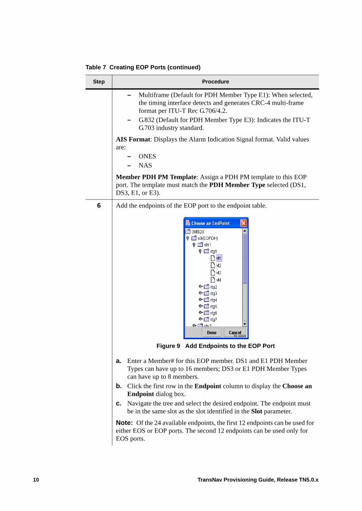
– Multiframe (Default for PDH Member Type E1): When selected, the timing interface detects and generates CRC-4 multi-frame format per ITU-T Rec G.706/4.2.
– G.832 (Default for PDH Member Type E3): Indicates the ITU-T G.703 industry standard.
AIS Format: Displays the Alarm Indication Signal format. Valid values are:
– ONES– NAS
Member PDH PM Template: Assign a PDH PM template to this EOP port. The template must match the PDH Member Type selected (DS1, DS3, E1, or E3).
6 Add the endpoints of the EOP port to the endpoint table.
Figure 9 Add Endpoints to the EOP Port
a. Enter a Member# for this EOP member. DS1 and E1 PDH Member Types can have up to 16 members; DS3 or E1 PDH Member Types can have up to 8 members.
b. Click the first row in the Endpoint column to display the Choose an Endpoint dialog box.
c. Navigate the tree and select the desired endpoint. The endpoint must be in the same slot as the slot identified in the Slot parameter.
Note: Of the 24 available endpoints, the first 12 endpoints can be used for either EOS or EOP ports. The second 12 endpoints can be used only for EOS ports.
Table 7 Creating EOP Ports (continued)
Step Procedure
10 TransNav Provisioning Guide, Release TN5.0.x
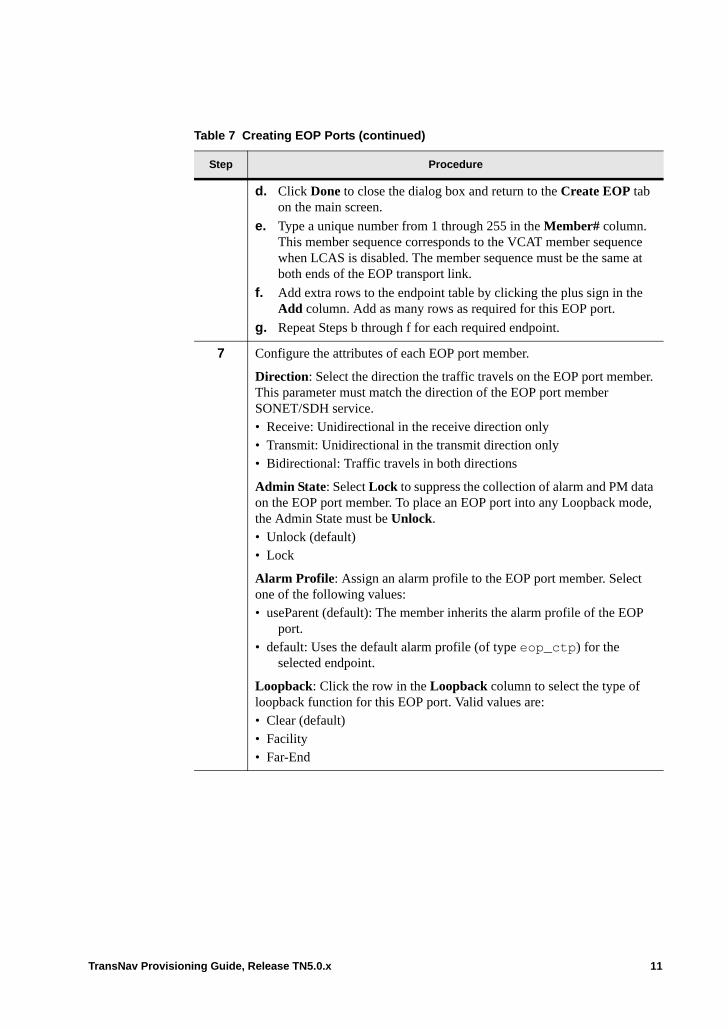
d. Click Done to close the dialog box and return to the Create EOP tab on the main screen.
e. Type a unique number from 1 through 255 in the Member# column. This member sequence corresponds to the VCAT member sequence when LCAS is disabled. The member sequence must be the same at both ends of the EOP transport link.
f. Add extra rows to the endpoint table by clicking the plus sign in the Add column. Add as many rows as required for this EOP port.
g. Repeat Steps b through f for each required endpoint.
7 Configure the attributes of each EOP port member.
Direction: Select the direction the traffic travels on the EOP port member. This parameter must match the direction of the EOP port member SONET/SDH service. • Receive: Unidirectional in the receive direction only• Transmit: Unidirectional in the transmit direction only• Bidirectional: Traffic travels in both directions
Admin State: Select Lock to suppress the collection of alarm and PM data on the EOP port member. To place an EOP port into any Loopback mode, the Admin State must be Unlock.• Unlock (default)• Lock
Alarm Profile: Assign an alarm profile to the EOP port member. Select one of the following values:• useParent (default): The member inherits the alarm profile of the EOP
port. • default: Uses the default alarm profile (of type eop_ctp) for the
selected endpoint.
Loopback: Click the row in the Loopback column to select the type of loopback function for this EOP port. Valid values are:• Clear (default) • Facility • Far-End
Table 7 Creating EOP Ports (continued)
Step Procedure
TransNav Provisioning Guide, Release TN5.0.x 11
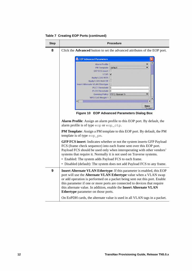
8 Click the Advanced button to set the advanced attributes of the EOP port.
Figure 10 EOP Advanced Parameters Dialog Box
Alarm Profile: Assign an alarm profile to this EOP port. By default, the alarm profile is of type eop or eop_ctp.
PM Template: Assign a PM template to this EOP port. By default, the PM template is of type eop_pm.
GFP FCS insert: Indicates whether or not the system inserts GFP Payload FCS (frame check sequence) into each frame sent over this EOP port. Payload FCS should be used only when interoperating with other vendors’ systems that require it. Normally it is not used on Traverse systems.• Enabled: The system adds Payload FCS to each frame.• Disabled (default): The system does not add Payload FCS to any frame.
9 Insert Alternate VLAN Ethertype: If this parameter is enabled, this EOP port will use the Alternate VLAN Ethertype value when a VLAN swap or add operation is performed on a packet being sent out this port. Enable this parameter if one or more ports are connected to devices that require this alternate value. In addition, enable the Insert Alternate VLAN Ethertype parameter on those ports.
On EoPDH cards, the alternate value is used in all VLAN tags in a packet.
Table 7 Creating EOP Ports (continued)
Step Procedure
12 TransNav Provisioning Guide, Release TN5.0.x

10 In the Queuing Policy parameter, specify how the queues are managed.
Note: Transmission times on EOP ports are slower than Ethernet links. EOP links could become severely congested if traffic on the Ethernet links overrun the port. For recommended set up information, see Ethernet over PDH (EOP) Requirements.
Select one of the following values: • FIFO (default): First-in, first-out. Select this queuing policy to schedule
all packets for transmission based on the FIFO algorithm. All traffic uses CoS1. Optionally, configure whether shaping should be employed using the FIFO Shaping Enable and the FIFO Shape Rate parameters. Go to Step 11.
• Priority: Select this queuing policy to schedule all packets for transmission based on strict priority, using three classes of service. There are three priorities: Highest priority traffic uses CoS1, medium priority traffic uses CoS2, and low priority traffic uses CoS3.
• WFQ: Weighted fair queuing. Select this queuing policy to guarantee a specific amount of the port’s bandwidth when there is congestion on the port. WFQ uses four classes of service and the guarantees are specified as weights. If the value in this parameter is WFQ, specify the weights in the four WFQ CoS weight {1 | 2 | 3 | 4} parameters. Go to Step 12.
11 If FIFO is the value in the Queuing Priority parameter, configure the following parameters:• FIFO Shape: Select Enabled to specify if the system will use the
number in the FIFO Shaping Rate parameter to shape the traffic being transmitted onto the port. Default is Disabled.
• FIFO Shaping Rate: If the FIFO Shaping parameter is enabled, enter a number between 1 and 1000 Mbps on EoPDH cards.
Table 7 Creating EOP Ports (continued)
Step Procedure
TransNav Provisioning Guide, Release TN5.0.x 13
12 If WFQ is the value in the Queuing Priority parameter, configure the following parameters:• WFQ CoS 1 Weight: Weighted queuing policy of CoS1. Enter a number
between 1 and 100 to determine the proportion of bandwidth on this port for CoS1. The default value is 1 which means packets with the CoS1 have no priority in relation to the other classes of service.
• WFQ CoS 2 Weight: Weighted queuing policy of CoS2. Enter a number between 1 and 100 to determine the proportion of bandwidth on this port for CoS2. The default value is 1 which means packets with the CoS2 have no priority in relation to the other classes of service.
• WFQ CoS 3 Weight: Weighted queuing policy of CoS3. Enter a number between 1 and 100 to determine the proportion of bandwidth on this port for CoS3. The default value is 1 which means packets with the CoS3 have no priority in relation to the other classes of service.
• WFQ CoS 4 Weight: Weighted queuing policy of CoS4. Enter a number between 1 and 100 to determine the proportion of bandwidth on this port for CoS4. The default value is 1 which means packets with the CoS4 have no priority in relation to the other classes of service.
13 Click Done to close the Advanced Parameters dialog box and return to the main screen.
14 Click Apply to create this EOP port and return to the Ethernet tab, EOP subtab.
15 The Creating EOP Ports procedure is complete. Continue to any of the following procedures according to your network plan:• Configure EOS port protection. See Chapter 44—“EOS Port Protection”• Configure LCAS. Chapter 47—“Link Capacity Adjustment Scheme”
Table 7 Creating EOP Ports (continued)
Step Procedure
14 TransNav Provisioning Guide, Release TN5.0.x

Chapter 46 EoPDH Services and Applications
Introduction This chapter contains the following information on unique features of the EoPDH cards in the Traverse system:• EoPDH Applications• Configuring CPE to Ethernet Information Flow• Configuring CPE to EoPDH Services Procedure• Managing Traffic on EOP Ports
EoPDH Applications
EoPDH cards can be configured to handle traffic from subtended customer premise equipment (CPE) devices to a Traverse node for switching and forwarding over the system. As such, the EoPDH is an access technology, not a transport technology. Frames from the CPE devices arrive at the Traverse on bonded PDH links, such as DS1s. Bonded PDH links are set up between the DS1s and EOP ports on EoPDH cards. From the EOP ports, the traffic is forwarded over the system using Traverse Ethernet services.
Multiple CPEs can be managed in groups from a single EoPDH card. Each group is a single IP subnet; each subnet is supported by an IP interface on the Traverse. The IP interface uses an Ethernet control channel (ECC) and a multiport aggregate bridge service on the EoPDH card to transport the IP packets between the CPE devices and the node. The ECC is an inter-node control channel that runs over Ethernet links and operates as a DCC.
The IP interface (called an ECC Interface or “ECCI”) is a numbered IP interface with one or more member ports. It must be configured on the Traverse.
Operators can configure a multi-port ECC service which uses a specific VLAN ID and IP address to allow in-band management of the IP traffic. Each EoPDH card can support 4 multipoint-ECC services and each node can support 16 multipoint ECC services.
For information on multipoint ECC services, see Chapter 49—“Creating Ethernet Services on Traverse,” Guidelines to Configure Ethernet Services on a Traverse Platform.
TransNav Provisioning Guide, Release TN5.0.x 1
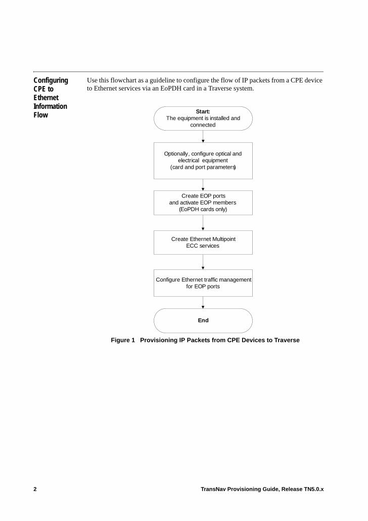
Configuring CPE to Ethernet Information Flow
Use this flowchart as a guideline to configure the flow of IP packets from a CPE device to Ethernet services via an EoPDH card in a Traverse system.
Figure 1 Provisioning IP Packets from CPE Devices to Traverse
Configure Ethernet traffic management for EOP ports
End
Create EOP ports and activate EOP members
(EoPDH cards only)
Start:The equipment is installed and
connected
Optionally, configure optical and electrical equipment
(card and port parameters)
Create Ethernet Multipoint ECC services
2 TransNav Provisioning Guide, Release TN5.0.x
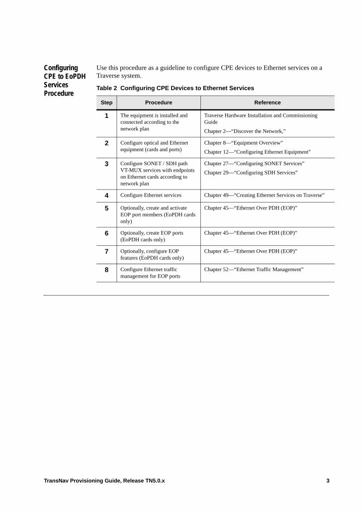
Configuring CPE to EoPDH Services Procedure
Use this procedure as a guideline to configure CPE devices to Ethernet services on a Traverse system.
Table 2 Configuring CPE Devices to Ethernet Services
Step Procedure Reference
1 The equipment is installed and connected according to the network plan
Traverse Hardware Installation and Commissioning Guide
Chapter 2—“Discover the Network,”
2 Configure optical and Ethernet equipment (cards and ports)
Chapter 8—“Equipment Overview”
Chapter 12—“Configuring Ethernet Equipment”
3 Configure SONET / SDH path VT-MUX services with endpoints on Ethernet cards according to network plan
Chapter 27—“Configuring SONET Services”
Chapter 29—“Configuring SDH Services”
4 Configure Ethernet services Chapter 49—“Creating Ethernet Services on Traverse”
5 Optionally, create and activate EOP port members (EoPDH cards only)
Chapter 45—“Ethernet Over PDH (EOP)”
6 Optionally, create EOP ports (EoPDH cards only)
Chapter 45—“Ethernet Over PDH (EOP)”
7 Optionally, configure EOP features (EoPDH cards only)
Chapter 45—“Ethernet Over PDH (EOP)”
8 Configure Ethernet traffic management for EOP ports
Chapter 52—“Ethernet Traffic Management”
TransNav Provisioning Guide, Release TN5.0.x 3
Managing Traffic on EOP Ports
Transmission times on EOP ports are slower than Ethernet links. This could cause EOP links to become severely congested if traffic on the Ethernet links overruns the port.
If low bandwidth, VOIP, or in band management is used on an EOP link, the port and services defaults will cause all traffic to compete for the same bandwidth. This, in turn, will cause the outbound EOP traffic (from the Traverse network to the EOP link) to congest the egress queues of the EOP link. (Drops in traffic will appear on a service PM report in the TX RED DISCARDS counter.)
To manage traffic congestion on the EOP port congestion, Force10 recommends using the following steps:• Change the port per hop behavior to WFQ or PRIORITY. The default of FIFO only
supports the default service COS of 1.• Classify time critical traffic (such as VOIP) as COS 1 or 2. In band management
traffic is fixed at COS 1.• Classify all other traffic at lower COS levels such as 3 or 4.
4 TransNav Provisioning Guide, Release TN5.0.x

Chapter 47 Link Capacity Adjustment Scheme
Introduction Link capacity adjustment scheme (LCAS) is a protocol defined in ITU G.7042, “Link capacity adjustment scheme (LCAS) for virtual concatenated signals.” Nodes at the ends of a virtually concatenated group (VCG) use this protocol to manage the group of concatenated SONET or SDH services. On EoPDH cards, this also applies to PDH services. Specifically, a system can adjust the group membership in response to autonomic events (member fail or recover) or operator requests (manually add or remove member). LCAS signaling between peers is carried in the SONET/SDH/PDH path overhead as outlined in G.7042 and G.707.
See the following topics for a complete description of LCAS capabilities on the Traverse system.• LCAS Operation• LCAS and Protection Groups• Asymmetric LCAS• LCAS Interworking• Before You Begin• Guidelines to Configure LCAS• Configure LCAS
If your network includes TE-206 nodes, LCAS must be disabled on the EOS of the Traverse or TE-100 node to allow RSTP on the TE-206 to interoperate seamlessly.
TransNav Provisioning Guide, Release TN5.0.x 1
LCAS Operation
On the Traverse system, LCAS operates on the members of an EOS or EOP port that are in a virtual concatenation group (VCG). The system can adjust the capacity of the VCG membership in response to autonomic events (member fail or recover) or operator requests (manually add or delete).
The Traverse considers a member (unprotected or protected) to be failed if there is a critical alarm associated with that member. The Traverse considers a failed member to have recovered when the critical alarm has cleared.
The system generates an LCAS event whenever a member fails or recovers. Also, if a member is added or deleted to the VCG, the event identifies the EOS or EOP port, the event type (failure or recovery), and the number of currently active members on the port.
On NGE and NGE Plus cards, LCAS-enabled EOS ports must face LCAS-enabled EOS ports on the far-end. If an LCAS-enabled EOS port on an NGE card faces a non-LCAS EOS port on the far end, unexpected behavior may occur.
Due to differences between SONET/SDH conditions and PDH conditions, some differences exist in how LCAS handles failed/deleted members on EOP ports. These differences are discussed separately below.
Failed or Deleted Members on EOS Ports. If a member of an LCAS-enabled VCG fails or is manually deleted, the system automatically removes the member from the VCG. However, the VGG continues to transfer data on the remaining members of the group. There will be a short period during which data being transmitted or received on the VCG is discarded.
When a member fails and the LCAS {LO | HO} Holdoff Timer is enabled on the EOS port, the system does not remove the member until the timer expires. If the SONET/SDH protection mechanism restores the member path, then the period during which data is discarded can be minimized. If the protection mechanism is not successful in restoring the member path, then the period during which data is discarded will be extended while LCAS removes the member from the group.
The system raises a path alarm when a member fails, identifying both the failure and the slot-port-path. The system clears the path alarm when the member recovers.
If LCAS has removed failed members, as long as at least one member remains Ethernet data continues to flow on any activated services that are using the VCG. However, the remaining bandwidth may be insufficient to satisfy the service bandwidth needs.
The system raises a total loss of capacity alarms (TCLT, TCLR) for the VCG as well as path alarms for the individual members when there are no members left in the group. The alarms clear when at least one member returns to health and is added back to the operating VCG. The system also generates partial loss of capacity alarms (PLCT, PLCR) depending on the provisioned thresholds.
If an operator removes the only member from an LCAS-enabled EOS port, the port will fail and the system will generate a “No Provisioned Members” alarm.
Restored or Added Members on EOS ports. When a previously failed member recovers, the system automatically uses LCAS to add the member to the VCG. No data drops when the member is added into the VCG. However, data is lost when an operator manually adds or removes another member to the group.
2 TransNav Provisioning Guide, Release TN5.0.x
If the LCAS {LO | HO} WTR timer is enabled on the EOS port, the system does not restore a failed member until the timer expires.
Failed or Deleted Members on EOP Ports. If an EOP member of an LCAS-enabled VCG fails due to an LOF, AIS, or LOM alarm, the system automatically removes the failed member from the VCAT group while the fault is present.
If an active EOP port member is in an IDLE fault condition, the member stays in the group, however, the system is unable to recover incoming frames resulting in a GFP fault.
Removing an LCAS on a PDH member occurs even if the administrative state of the member has been locked.
EOP port members provide a Loopback option. If an EOP port member is provisioned with Facility Loopback, the system cannot send a source signal on the looped-back member. The system removes the member from the VCAT group even if the member has been locked.
EOS Port Thresholds. To receive a loss of capacity alarm for an EOS port, the operator can set the threshold limits for the PLCR Threshold (Partial Loss of Capacity, Receive) and PLCT Threshold (Partial Loss of Capacity, Transmit) fields on the Advanced Parameters tab. The thresholds are based on ITU-T standard G.806. If set to zero (the default), the system generates a total loss of capacity (TLCR or TLCT) alarm. The following examples show how these thresholds can be used:
Example 1:
An LCAS-enabled EOS port in your system is configured on which you expect to send and receive up to 1 Gbps of Ethernet data. It is provisioned as an STS-1-21v. In order to carry a gigabit, every one of those 21 members must be up. If some (but not all) of the members go down, the EOS port is still carrying traffic but at a reduced capacity that does not meet your performance goals. In this example, you would set the PLCT and PLCR Thresholds to 21. This setting will cause a PLCT or PLCR alarm that would notify the operator if the number of correctly-operating members ever falls below 21. If the number ever goes to zero, the Traverse system sends a TLCT or TLCR (Total Loss of Capacity, Transmit/Receive) alarm instead of a PLCT/PLCR alarm.
Example 2:
An LCAS-enabled EOS port in your system is configured on which you expect to send and receive up to 220 Mbps of Ethernet data. For that amount of traffic, 5 STSs are needed. You decide to provision the EOS port with 10 members (STS-1-10v), using strict routing to send 5 members on one route through the network and 5 members on a different route. Any single point of failure in your network will only take down 5 members, leaving you with a sufficient number to carry the required 220 Mbps of traffic. In this example, you would set the PLCT and PLCR Thresholds to 5. If the number of correctly-operating members falls below 10 but is still at least 5, your traffic is okay and an alarm is not generated. However, if the number of correctly-operating members ever falls below 5, the system will fall below your required capacity and generate a PLCR or PLCT alarm. Note that when all 10 members are up, you are actually able to send well over the required 220 Mbps of Ethernet traffic. Anything
TransNav Provisioning Guide, Release TN5.0.x 3
above 220 Mbps is “extra traffic” that you would be willing to lose during a network fault.
LCAS and Protection Groups
Members of a VCG can be part of a protection group or 1+1 path protected. An unprotected member has a single transport path. A protected member has two transport paths that operate as a path protection group.
When a member is protected, failure of one path will not cause a critical alarm; failure of both paths will. When both paths are failed, the recovery of one path removes the critical alarm.
The LCAS {LO | HO} Holdoff Timer should always be enabled when the VCG members are protected and always be disabled when VCG members are unprotected.
Asymmetric LCAS
Asymmetric LCAS arises when an LCAS-enabled VCG is configured with different bandwidth in each direction. However, there must be at least one path in each direction for LCAS to work. For example, you can configure three uni-directional paths from Node1 to Node2 using STS1, STS2, STS3, and one uni-directional path from Node2 to Node1 using STS10.
The Traverse system correctly transmits and receives Ethernet data when some (but not all) of the members of the VCG are uni-directional paths.
In addition, the Traverse system correctly transmits and receives Ethernet data when some (but not all) of the members of the VCG are bi-directional paths that have failed in only one direction.
LCAS Interworking
When two nodes use virtual concatenation for a network connection, it is possible that one side is configured to use LCAS on the connection and the other side is not (or does not support LCAS). That is, when a node is using LCAS it sends LCAS control messages. If a Traverse node does not receive any LCAS control messages, it assumes that the peer is not using LCAS.
4 TransNav Provisioning Guide, Release TN5.0.x
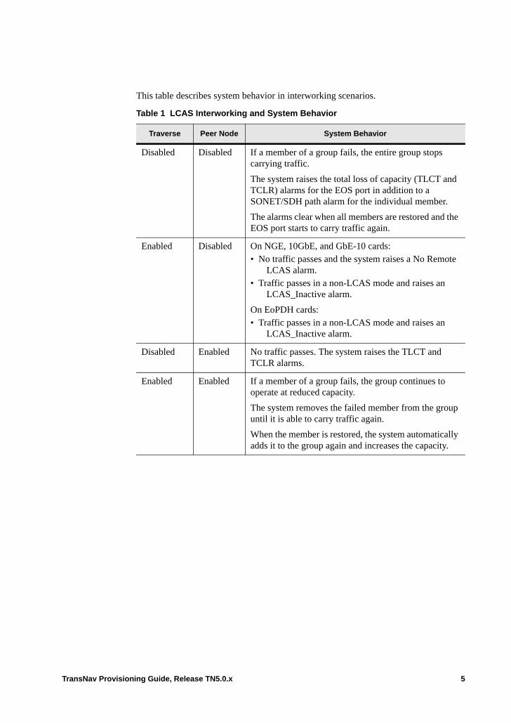
This table describes system behavior in interworking scenarios.
Table 1 LCAS Interworking and System Behavior
Traverse Peer Node System Behavior
Disabled Disabled If a member of a group fails, the entire group stops carrying traffic.
The system raises the total loss of capacity (TLCT and TCLR) alarms for the EOS port in addition to a SONET/SDH path alarm for the individual member.
The alarms clear when all members are restored and the EOS port starts to carry traffic again.
Enabled Disabled On NGE, 10GbE, and GbE-10 cards:• No traffic passes and the system raises a No Remote
LCAS alarm.• Traffic passes in a non-LCAS mode and raises an
LCAS_Inactive alarm.
On EoPDH cards:• Traffic passes in a non-LCAS mode and raises an
LCAS_Inactive alarm.
Disabled Enabled No traffic passes. The system raises the TLCT and TCLR alarms.
Enabled Enabled If a member of a group fails, the group continues to operate at reduced capacity.
The system removes the failed member from the group until it is able to carry traffic again.
When the member is restored, the system automatically adds it to the group again and increases the capacity.
TransNav Provisioning Guide, Release TN5.0.x 5
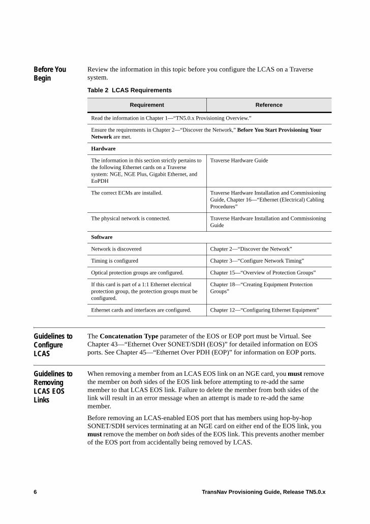
Before You Begin
Review the information in this topic before you configure the LCAS on a Traverse system.
Guidelines to Configure LCAS
The Concatenation Type parameter of the EOS or EOP port must be Virtual. See Chapter 43—“Ethernet Over SONET/SDH (EOS)” for detailed information on EOS ports. See Chapter 45—“Ethernet Over PDH (EOP)” for information on EOP ports.
Guidelines to Removing LCAS EOS Links
When removing a member from an LCAS EOS link on an NGE card, you must remove the member on both sides of the EOS link before attempting to re-add the same member to that LCAS EOS link. Failure to delete the member from both sides of the link will result in an error message when an attempt is made to re-add the same member.
Before removing an LCAS-enabled EOS port that has members using hop-by-hop SONET/SDH services terminating at an NGE card on either end of the EOS link, you must remove the member on both sides of the EOS link. This prevents another member of the EOS port from accidentally being removed by LCAS.
Table 2 LCAS Requirements
Requirement Reference
Read the information in Chapter 1—“TN5.0.x Provisioning Overview.”
Ensure the requirements in Chapter 2—“Discover the Network,” Before You Start Provisioning Your Network are met.
Hardware
The information in this section strictly pertains to the following Ethernet cards on a Traverse system: NGE, NGE Plus, Gigabit Ethernet, and EoPDH
Traverse Hardware Guide
The correct ECMs are installed. Traverse Hardware Installation and Commissioning Guide, Chapter 16—“Ethernet (Electrical) Cabling Procedures”
The physical network is connected. Traverse Hardware Installation and Commissioning Guide
Software
Network is discovered Chapter 2—“Discover the Network”
Timing is configured Chapter 3—“Configure Network Timing”
Optical protection groups are configured. Chapter 15—“Overview of Protection Groups”
If this card is part of a 1:1 Ethernet electrical protection group, the protection groups must be configured.
Chapter 18—“Creating Equipment Protection Groups”
Ethernet cards and interfaces are configured. Chapter 12—“Configuring Ethernet Equipment”
6 TransNav Provisioning Guide, Release TN5.0.x

Removing an LCAS-enabled EOS port from a 10GbE, GbE-10, or EoPDH card requires terminating services on only one end of the link. To remove a member from an LCAS EOP link on an EoPDH card also requires terminating services on only one end of the link.
If another member of the EOS port is accidentally removed by LCAS, users can repair the error by either reactivating the service, removing the remote EOS member, or re-adding the local EOS member.
TransNav Provisioning Guide, Release TN5.0.x 7
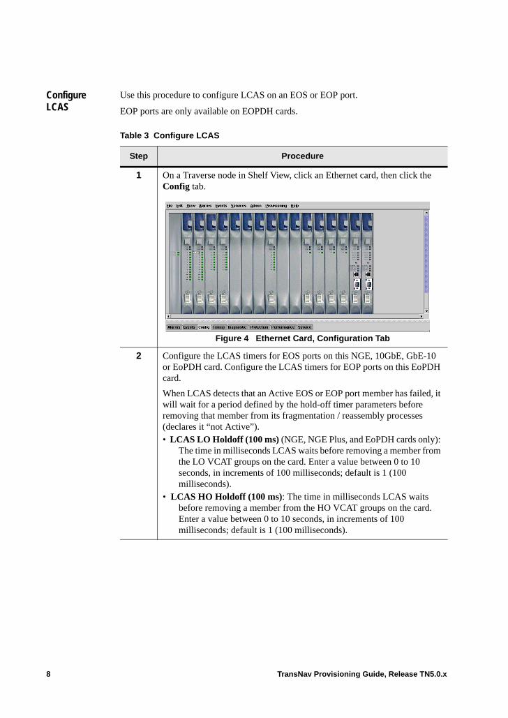
Configure LCAS
Use this procedure to configure LCAS on an EOS or EOP port.
EOP ports are only available on EOPDH cards.
Table 3 Configure LCAS
Step Procedure
1 On a Traverse node in Shelf View, click an Ethernet card, then click the Config tab.
Figure 4 Ethernet Card, Configuration Tab
2 Configure the LCAS timers for EOS ports on this NGE, 10GbE, GbE-10 or EoPDH card. Configure the LCAS timers for EOP ports on this EoPDH card.
When LCAS detects that an Active EOS or EOP port member has failed, it will wait for a period defined by the hold-off timer parameters before removing that member from its fragmentation / reassembly processes (declares it “not Active”). • LCAS LO Holdoff (100 ms) (NGE, NGE Plus, and EoPDH cards only):
The time in milliseconds LCAS waits before removing a member from the LO VCAT groups on the card. Enter a value between 0 to 10 seconds, in increments of 100 milliseconds; default is 1 (100 milliseconds).
• LCAS HO Holdoff (100 ms): The time in milliseconds LCAS waits before removing a member from the HO VCAT groups on the card. Enter a value between 0 to 10 seconds, in increments of 100 milliseconds; default is 1 (100 milliseconds).
8 TransNav Provisioning Guide, Release TN5.0.x
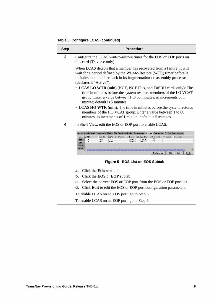
3 Configure the LCAS wait-to-restore times for the EOS or EOP ports on this card (Traverse only).
When LCAS detects that a member has recovered from a failure, it will wait for a period defined by the Wait-to-Restore (WTR) timer before it includes that member back in its fragmentation / reassembly processes (declares it “Active”).• LCAS LO WTR (min) (NGE, NGE Plus, and EoPDH cards only): The
time in minutes before the system restores members of the LO VCAT group. Enter a value between 1 to 60 minutes, in increments of 1 minute; default is 5 minutes.
• LCAS HO WTR (min): The time in minutes before the system restores members of the HO VCAT group. Enter a value between 1 to 60 minutes, in increments of 1 minute; default is 5 minutes.
4 In Shelf View, edit the EOS or EOP port to enable LCAS.
Figure 5 EOS List on EOS Subtab
a. Click the Ethernet tab.
b. Click the EOS or EOP subtab.
c. Select the correct EOS or EOP port from the EOS or EOP port list.
d. Click Edit to edit the EOS or EOP port configuration parameters.
To enable LCAS on an EOS port, go to Step 5.
To enable LCAS on an EOP port, go to Step 6.
Table 3 Configure LCAS (continued)
Step Procedure
TransNav Provisioning Guide, Release TN5.0.x 9
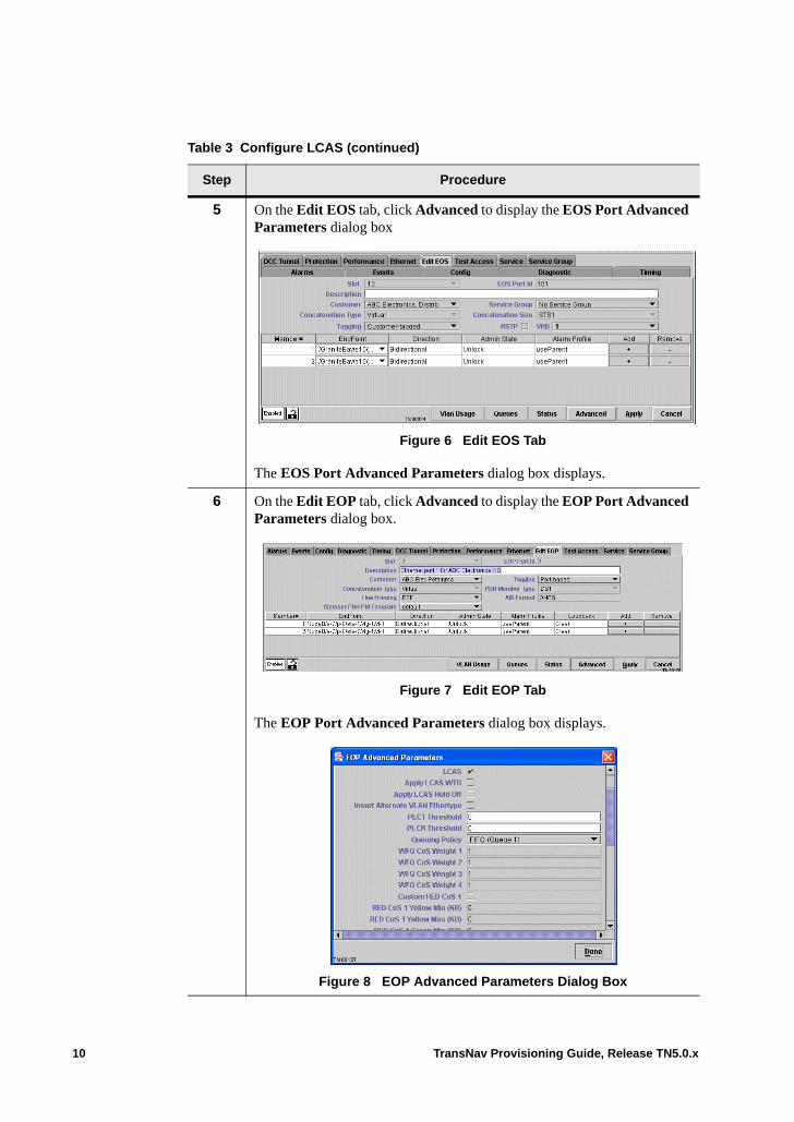
5 On the Edit EOS tab, click Advanced to display the EOS Port Advanced Parameters dialog box
.
Figure 6 Edit EOS Tab
The EOS Port Advanced Parameters dialog box displays.
6 On the Edit EOP tab, click Advanced to display the EOP Port Advanced Parameters dialog box.
.
Figure 7 Edit EOP Tab
The EOP Port Advanced Parameters dialog box displays.
Figure 8 EOP Advanced Parameters Dialog Box
Table 3 Configure LCAS (continued)
Step Procedure
10 TransNav Provisioning Guide, Release TN5.0.x
7 Find and configure the following LCAS parameters for this EOS or EOP port:
LCAS: Enables or disables LCAS operations for this EOS or EOP port.• Select (default): Select the checkbox to enable LCAS to manage VCG
membership on this port. The system can remove any failed members from this service and continue to use this EOS or EOP port at a reduced capacity.
• Unselect (clear the checkbox): VCG membership is statically configured. The system stops carrying any traffic if a member fails or is removed from the VCG.
Apply LCAS WTR (Traverse only): Select the checkbox to apply the LCAS wait-to-restore value to this port.• Select: Use the value specified in the LCAS {LO | HO} WTR timer
(Step 3).• Unselect (default): Do not use the wait-to-restore value.
Apply LCAS Hold Off:• Select: Use the value specified in the LCAS {LO | HO} Holdoff
(100ms) timer (Step 2).• Unselect (default)
PLCT Threshold: Partial Loss of Capacity, Transmit (PLCT) Threshold. Indicates the number of provisioned EOS or EOP port source (transmit) members that should be operating correctly in order for the EOS or EOP port to carry its expected throughput. Whenever the number of correctly-operating source members falls below this threshold, the system will raise a PLCT alarm on the EOS or EOP port. Used only when the EOS or EOP port has LCAS enabled and has at least one provisioned member. Enter a number between 0 and 64 for NGE and EoPDH cards or 192 for 10GbE and GbE-10 cards. The default is 0, which means that the PLCT alarm will not be raised on this EOS or EOP port.
PLCR Threshold: Partial Loss of Capacity, Receive (PLCR) Threshold. Indicates the number of provisioned EOS or EOP port source (receive) members that should be operating correctly in order for the EOS or EOP port to carry its expected throughput. Whenever the number of correctly-operating source members falls below this threshold, the system will raise a PLCR alarm on the EOS or EOP port. Used only when the EOS or EOP port has LCAS enabled and has at least one provisioned member. Enter a number between 0 and 64 for NGE and EoPDH cards or 192 for 10GbE and GbE-10 cards. The default is 0, which means that the PLCT alarm will not be raised on this EOS or EOP port.
Table 3 Configure LCAS (continued)
Step Procedure
TransNav Provisioning Guide, Release TN5.0.x 11
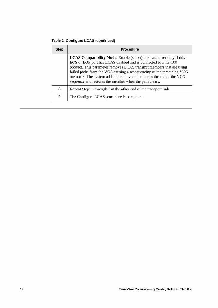
LCAS Compatibility Mode: Enable (select) this parameter only if this EOS or EOP port has LCAS enabled and is connected to a TE-100 product. This parameter removes LCAS transmit members that are using failed paths from the VCG causing a resequencing of the remaining VCG members. The system adds the removed member to the end of the VCG sequence and restores the member when the path clears.
8 Repeat Steps 1 through 7 at the other end of the transport link.
9 The Configure LCAS procedure is complete.
Table 3 Configure LCAS (continued)
Step Procedure
12 TransNav Provisioning Guide, Release TN5.0.x
Chapter 48 Rapid Spanning Tree Protocol
Introduction This chapter contains the following topics:• What is RSTP?• Supported RSTP Topologies• RSTP Bridge Management• RSTP Port Management• Guidelines to Configure RSTP• Virtual RSTP• Before You Begin
– Before You Begin Configuring RSTP on TE-100 Nodes• Configure RSTP on an EOS Port• View RSTP Port Status• Configure Virtual RSTP
TransNav Provisioning Guide, Release TN5.0.x 1
What is RSTP? Spanning Tree Protocol (STP), defined in the IEEE 802.1D standard, is a widely used technique for eliminating loops and providing path redundancy in a Layer 2 packet-switched network. Fundamentally, STP provides an algorithm that enables a switch to identify the most efficient data transmission path to use when faced with multiple paths. In the event that the best path fails, the algorithm recalculates and finds the next most efficient path.
Although effective, the protocol faces one significant drawback that limits its applicability in networks carrying delay-sensitive voice and video traffic: STP has lengthy fail-over and recovery times. Depending upon the complexity of the network topology, STP can take as long as 30 to 60 seconds to detect the change and reconverge after a link failure.
Rapid Reconfiguration of Spanning Tree (RSTP - IEEE 802.1w) is an amendment to the original IEEE 802.1D standard and specifically addresses these limitations for applications in carrier-class networks requiring high levels of resiliency and availability. RSTP reduces the time it takes to reconfigure and restore services after a link failure to sub-second levels, while retaining compatibility with existing STP equipment.
RSTP is a transport technology based on a distributed algorithm that selects a single switch in the network topology to act as the root of the spanning tree. The algorithm assigns port roles to individual ports on each switch. Port roles determine whether the port is to be part of the active topology connecting the bridge or switch to the root bridge (a root port), or connecting a LAN through the switch to the root bridge (a designated port).
Regardless of their roles, ports can serve as alternate or redundant ports that provide connectivity in the event of a failure. For example, when bridges, switches, bridge ports, or entire LANs fail or disappear.
2 TransNav Provisioning Guide, Release TN5.0.x

Supported RSTP Topologies
In Traverse Ethernet applications, enable RSTP among Traverse nodes that participate in bridge services to ensure that the Ethernet topology used to forward packets among the nodes is loop free. The Traverse supports both ring and mesh RSTP topologies.
This diagram illustrates how RSTP might create a spanning tree out of an Ethernet ring. In this example, each Ethernet card (module) is in a separate Traverse node.
The lines between cards represent the point-to-point links that connect the RSTP bridges. These links are SONET/SDH connections that can be either contiguous concatenation paths or virtual concatenation groups. The dashed lines represent customer Ethernet ports.
Figure 1 Supported RSTP Topology
IEEE 802.1w defines an RSTP port to have one of the following roles:• Root (R) ports forward Ethernet frames. The system has decided to use this port to
reach the Root Bridge.• Designated (D) ports also forward Ethernet frames. • Alternate (A) ports are blocked but can quickly become forwarding ports when the
topology is reconfigured. In this diagram, one of the links is blocked (heavy line) at one node. The node that has blocked the link does not send or receive any packets on that link. This blockage prevents packets from looping around the ring.
• Edge (E) ports are those that have no further bridges downstream. RSTP does not run on these ports.
ETH
ETH
ETH
ETH
R: Root PortD: Designated portA: Alternate portE: Edge portRoot: Root Bridge of network
R
D
D
Root
D
R
DR D
R DD
RD
R
R
A
E
E
ETH
ETH
E
E
E
E
E
E
ETH ETH
TransNav Provisioning Guide, Release TN5.0.x 3
RSTP Bridge Management
An RSTP bridge is a network element that carries out Layer 2 Ethernet processing (maintaining forwarding tables, making forwarding decisions, and flooding packets). On the Traverse system, an RSTP bridge is represented by the Ethernet card itself.
The Traverse system has one RSTP bridge per Ethernet card. The RSTP bridge attributes are viewable on the Config tab of the Ethernet card.
Note: On Traverse nodes only, up to 20 virtual copies of RSTP (V-RSTP) can be run on the same Ethernet card. For more information, see Virtual RSTP, page 7.• RSTP Bridge ID (Read-only): An identifier for this card used in the RSTP protocol.
Displayed in the following hexidecimal format: <BridgePriority>000-<MAC address>. Example: 8000-1b2000c144d8. When two cards are in a 1:1 equipment protection group, each card has a different RSTP Bridge ID, even though only one of the cards is included in the spanning tree topology at any time.
• RSTP Bridge Priority: Enter an integer between 0 and 15; default is 8. The bridge card with the lowest Bridge Priority in the spanning tree topology will be selected as the Root Bridge. If the lowest Bridge Priority is shared by multiple bridges, the one with the smallest numerical MAC address will be selected as the Root Bridge. If you do not change the Bridge Priority of any card from its default of 8, this means that the card in the RSTP topology with the lowest MAC address becomes the Root Bridge. When two cards are in a 1:1 equipment protection group, this value applies to both cards.
• RSTP Root Port ID (Read-only): The EOS port on this card that currently provides the lowest cost path to the root bridge.
• RSTP Root Bridge ID (Read-only): The Bridge ID of the card that is currently selected as Root Bridge for the spanning tree topology. If the current Root Bridge is the Active card in a 1:1 equipment protection group, and there is a protection switch that moves operation from that card to the other card in the protection group, then the spanning tree topology will select a new Root Bridge, which may or may not be the other card in the protection group.
RSTP Port Management
An RSTP port is the endpoint of a link that sends and receives packets. On the Traverse system, an RSTP port is represented by the EOS port type.
On an EOS port, configure the following parameters to enable RSTP on the EOS port:• RSTP: Enables or disables RSTP for Bridge services.
– Select Enabled to enable RSTP on this EOS port for bridge services.– Select Disabled to disable RSTP for bridge services.
• RSTP Path Cost: Set the path cost of this link. The total cost of a path between any card and the root bridge is the sum of the costs of all the links in the path. Lower values of this parameter mean that this port is more likely to be included in the lowest cost (more desirable) path from this or any other card to the root bridge. Enter an integer between 1 and 16; default is 1.
4 TransNav Provisioning Guide, Release TN5.0.x
• RSTP Port Priority: Used when the spanning tree algorithm has determined that several ports on the card provide paths of equal total cost to the root bridge. The port with the lowest Port Priority is chosen as the Root Port. If several ports have the same lowest Port Priority, then the port with the lowest EOS Port ID is chosen as the Root Port. Enter an integer between 1 and 15; default is 8.
See View RSTP Port Status to view the status of the RSTP port. RSTP port state parameters are as follows: • RSTP Port State (Read-only): Indicates the status of the selected port.
– Disabled: This EOS port is not forwarding packets and is not participating in the RSTP operation.
– Listening: This EOS port is preparing to forward packets. It is temporarily disabled to prevent loops which may occur as the active topology of the LAN changes. Learning is disabled since changes in active topology can lead to incorrect information when the topology becomes stable.
– Learning: This EOS port is preparing to forward packets. It is temporarily disabled to prevent loops which may occur as the active topology of the LAN changes. Learning is enabled to collect information prior to forwarding, in order to reduce the number of frames unnecessarily forwarded.
– Forwarding: This EOS port is forwarding packets.– Blocking: This EOS port is not forwarding packets. It is preventing packets
from looping in the active topology.– Undefined: This EOS port is not using RSTP at all. Either this EOS port does
not have RSTP configured or there is no activated bridge service using this EOS port.
• RSTP Port Role (Read-only): This field reads one of the following values.– Alternate: Ports are blocked but can quickly become forwarding ports when
the topology is reconfigured. The node that has blocked the link does not send or receive any packets on that link. This blockage prevents packets from looping around the ring.
– Designated: This EOS port forwards Ethernet frames. – Disabled: RSTP is not enabled for this EOS port.– Root: The system has decided to use this port to reach the Root Bridge. This
port also forwards Ethernet frames.
Guidelines to Configure RSTP
Before you create an EOS port with RSTP enabled for a bridge service, review the following guidelines:• On a Traverse system, the RSTP implementation is intended only to operate within
the Traverse network. The Traverse implementation of RSTP runs on EOS ports and does not run on any physical Ethernet ports. Multiple Ethernet cards in the same node can participate in the same RSTP ring. That is, an RSTP network can contain multiple RSTP bridges in the same Traverse node.
• On a TE-100 system, the implementation of RSTP is intended only to operate within a network of TraverseEdge nodes using Release TN5.0.x software. RSTP runs on EOS ports and does not run on any physical Ethernet ports.
• Enable RSTP in the Advanced Parameters dialog box of an EOS port. • All EOS port members must be bi-directional links for RSTP to be enabled.
TransNav Provisioning Guide, Release TN5.0.x 5
• The EOS port must be an endpoint in one or more bridge services. By enabling RSTP on an EOS port, the port broadcasts that it will forward (based on the MAC address) any packets sent to it. However, when an EOS port doesn’t participate in any Bridge service, it does not perform MAC forwarding at all.
• RSTP supports any Ethernet topology (“RSTP network”) that consists of a set of Ethernet cards (“RSTP bridges”) interconnected by SONET/SDH transport connections (“RSTP links”) where:– In a Traverse system, the number of RSTP links supported by a single RSTP
bridge is up to at least 64 (all 64 EOS ports).– In a TE-100 system, the number of RSTP links supported by a single RSTP
bridge is up to at least 8 (all 8 EOS ports).– The number of RSTP bridges in the more complex (mesh) topology is any
number up to at least 200.– The number of card-to-card hops between RSTP bridges is up to at least 32.
• The Traverse and TE-100 platforms support both ring and mesh RSTP topologies. • There can be up to 200 Ethernet cards in an RSTP topology, but there cannot be more
than 32 hops to the RSTP Root Bridge.• There can be up to 32 Ethernet cards in a ring topology.• On average, RSTP may take up to three seconds to reconverge whenever there is a
topology change in a ring topology network. In a Traverse system, RSTP may take between 15 and 45 seconds to reconverge on a mesh topology on average. A topology change includes the addition, removal, failure, or recovery of Ethernet cards or links participating in the RSTP network.
Note: If your network includes TE-206 nodes, LCAS must be disabled on the EOS of the Traverse or TE-100 node to allow RSTP on the TE-206 to interoperate seamlessly.
If a customer uses 802.1d Spanning Tree Protocol (STP) within their own topology, the network is completely transparent to any such STP or RSTP implementation. That is, it looks like a multipoint LAN to which the customer’s devices are connected.
Spanning Tree BPDUs. On Traverse nodes only, if the Queuing Policy for this EOS port is WFQ, then all service data sent to the EOS port is queued on one of four service data queues. However, there is no separate system queue available for exclusive use of RSTP packets. The system uses CoS4 (queue 4).
Using CoS4 poses the following limitations:• BPDU (bridge protocol data unit) packets may get queued behind lots of CoS 4
service packets, leading to undesirably long delays.• If CoS 4 is assigned a Weight of 1, then packets of this CoS are transmitted only
when other CoSs with Weights other than one are not using their weighted proportion of the available bandwidth. If other CoS’s on this EOS port are using all of their weighted proportion, the scheduler for this EOS port will always select packets from those CoS’s, leading to undesirably long delays for CoS 4 packets, including RSTP.
Therefore, if WFQ is the Queuing Policy and RSTP is enabled for this EOS port in an activated bridge service, use the following guidelines:
6 TransNav Provisioning Guide, Release TN5.0.x

• Ensure that the WFQ Weight CoS 4 parameter has a weight of more than one. Force10 recommends setting weights on the EOS port such that value in the WFQ Weight CoS4 parameter is at least 5% of the total.
• Ensure that the amount of CoS 4 service data queued for the EOS port is always small (one). For example, use Classifiers on the service-ports of the bridge service that do NOT classify packets into CoS4, or configure very small RED thresholds for the CoS 4 queues. (BPDUs are always queued without regard to RED thresholds, so setting small or even zero RED thresholds will not impede the transmission of BPDUs.)
Virtual RSTP On the Traverse system, up to 20 virtual copies of RSTP (V-RSTP) can be run on the same Ethernet card. This feature is available on Traverse nodes only. Each copy, called a Virtual RSTP Bridge (VRB), uses an exclusive set of EOS ports that terminate on the card. Different EOS ports on each node can be assigned to VRBs to form completely separate spanning trees for individual customers; each bridge service can be in a different spanning tree.
After the SONET/SDH services are set up and the bandwidths are determined, Force10 recommends first setting up the VRB structure, then creating the EOS ports, assigning a VRB number to each link of the bridge service, enabling RSTP on each EOS port, and finally, creating the EOS and bridge services on each node.
Configure the following parameters to set up the VRB structure on the Ethernet tab of each Ethernet card:
VRB: Indicates a number to identify the virtual RSTP bridge being created. Valid values are 1 to 20; default is 1.
Bridge Priority: Indicates a number from 1 to 8 to indicate the priority of this bridge; default is 8. The bridge with the lowest Bridge Priority in the spanning tree topology will be selected as the Root Bridge. If the lowest Bridge Priority is shared by multiple bridges, the bridge with the smallest numerical MAC address will be selected as the Root Bridge. When two cards are in a 1:1 equipment protection group, this value applies to both cards.
Name: Indicates the name for this VRB. Names are case sensitive. They must be 2 to 32 characters in length, be alphanumeric, and contain no special characters. Hyphens (-) and spaces are allowed.
TransNav Provisioning Guide, Release TN5.0.x 7
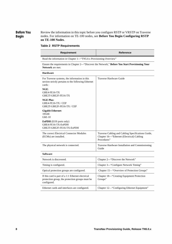
Before You Begin
Review the information in this topic before you configure RSTP or VRSTP on Traverse nodes. For information on TE-100 nodes, see Before You Begin Configuring RSTP on TE-100 Nodes.
Table 2 RSTP Requirements
Requirement Reference
Read the information in Chapter 1—“TN5.0.x Provisioning Overview”
Ensure the requirements in Chapter 2—“Discover the Network,” Before You Start Provisioning Your Network are met.
Hardware
For Traverse systems, the information in this section strictly pertains to the following Ethernet cards :
NGE: GBE4-FE16-TX GBE2T-GBE2F-FE16-TX
NGE Plus: GBE4-FE16-TX / CEPGBE2T-GBE2F-FE16-TX / CEP
Gigabit Ethernet: 10GbEGbE-10
EoPDH (EOS ports only) GBE4-FE16-TX-EoPDHGBE2T-GBE2F-FE16-TX-EoPDH
Traverse Hardware Guide
The correct Electrical Connector Modules (ECMs) are installed.
Traverse Cabling and Cabling Specifications Guide, Chapter 16—“Ethernet (Electrical) Cabling Procedures”
The physical network is connected. Traverse Hardware Installation and Commissioning Guide
Software
Network is discovered. Chapter 2—“Discover the Network”
Timing is configured. Chapter 3—“Configure Network Timing”
Optical protection groups are configured. Chapter 15—“Overview of Protection Groups”
If this card is part of a 1:1 Ethernet electrical protection group, the protection groups must be configured.
Chapter 18—“Creating Equipment Protection Groups”
Ethernet cards and interfaces are configured. Chapter 12—“Configuring Ethernet Equipment”
8 TransNav Provisioning Guide, Release TN5.0.x

Before You Begin Configuring RSTP on TE-100 Nodes
Review the information in this topic before you configure RSTP onTE-100 nodes.
Table 49 RSTP Requirements
Requirement Reference
Read the information in Chapter 26—“Configuring the Network.”
Hardware
The physical network is connected. TraverseEdge 100 User Guide, Chapter 1—“Installation Overview”
Software
Nodes are commissioned. TraverseEdge 100 User Guide, Chapter 10—“Node Start-up and Initial Configuration”
Timing is configured. TraverseEdge 100 User Guide, Chapter 2—“Configuring Network Timing”
Optical protection groups are configured. TraverseEdge 100 User Guide
Chapter 3—“Creating a UPSR/SNCP Protection Group”
Chapter 4—“Creating 1+1APS/MSP Protection Groups”
Chapter 5—“Creating a 1+1 Optimized Protection Group”
Ethernet modules and interfaces are configured. TraverseEdge 100 User Guide, Chapter 36—“Configuring Ethernet Equipment on TE-100 Nodes”
EOS ports are configured. TransNav Management System Provisioning Guide, Chapter 43—“Ethernet Over SONET/SDH (EOS)”
TransNav Provisioning Guide, Release TN5.0.x 9
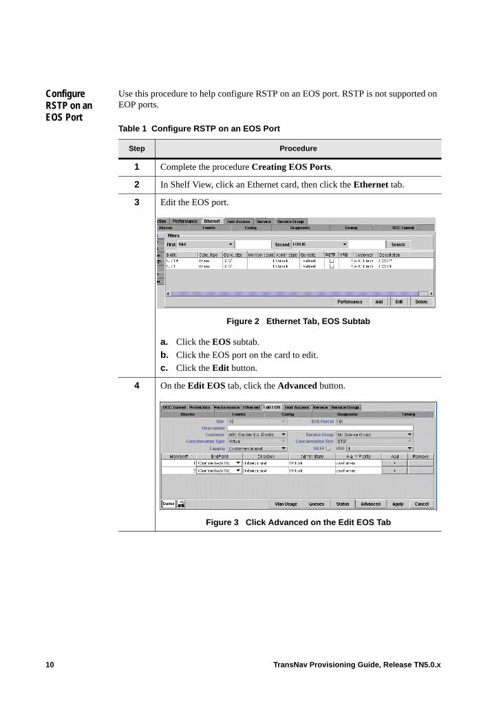
Configure RSTP on an EOS Port
Use this procedure to help configure RSTP on an EOS port. RSTP is not supported on EOP ports.
Table 1 Configure RSTP on an EOS Port
Step Procedure
1 Complete the procedure Creating EOS Ports.
2 In Shelf View, click an Ethernet card, then click the Ethernet tab.
3 Edit the EOS port..
Figure 2 Ethernet Tab, EOS Subtab
a. Click the EOS subtab.
b. Click the EOS port on the card to edit.
c. Click the Edit button.
4 On the Edit EOS tab, click the Advanced button.
Figure 3 Click Advanced on the Edit EOS Tab
10 TransNav Provisioning Guide, Release TN5.0.x
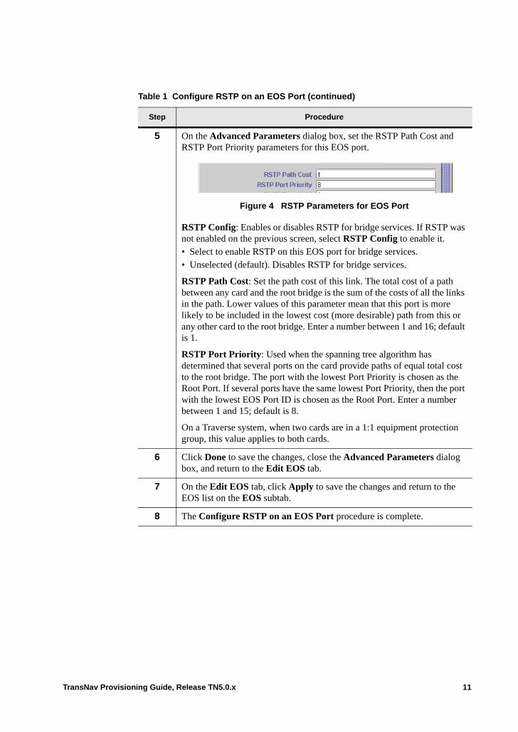
5 On the Advanced Parameters dialog box, set the RSTP Path Cost and RSTP Port Priority parameters for this EOS port.
Figure 4 RSTP Parameters for EOS Port
RSTP Config: Enables or disables RSTP for bridge services. If RSTP was not enabled on the previous screen, select RSTP Config to enable it.• Select to enable RSTP on this EOS port for bridge services.• Unselected (default). Disables RSTP for bridge services.
RSTP Path Cost: Set the path cost of this link. The total cost of a path between any card and the root bridge is the sum of the costs of all the links in the path. Lower values of this parameter mean that this port is more likely to be included in the lowest cost (more desirable) path from this or any other card to the root bridge. Enter a number between 1 and 16; default is 1.
RSTP Port Priority: Used when the spanning tree algorithm has determined that several ports on the card provide paths of equal total cost to the root bridge. The port with the lowest Port Priority is chosen as the Root Port. If several ports have the same lowest Port Priority, then the port with the lowest EOS Port ID is chosen as the Root Port. Enter a number between 1 and 15; default is 8.
On a Traverse system, when two cards are in a 1:1 equipment protection group, this value applies to both cards.
6 Click Done to save the changes, close the Advanced Parameters dialog box, and return to the Edit EOS tab.
7 On the Edit EOS tab, click Apply to save the changes and return to the EOS list on the EOS subtab.
8 The Configure RSTP on an EOS Port procedure is complete.
Table 1 Configure RSTP on an EOS Port (continued)
Step Procedure
TransNav Provisioning Guide, Release TN5.0.x 11
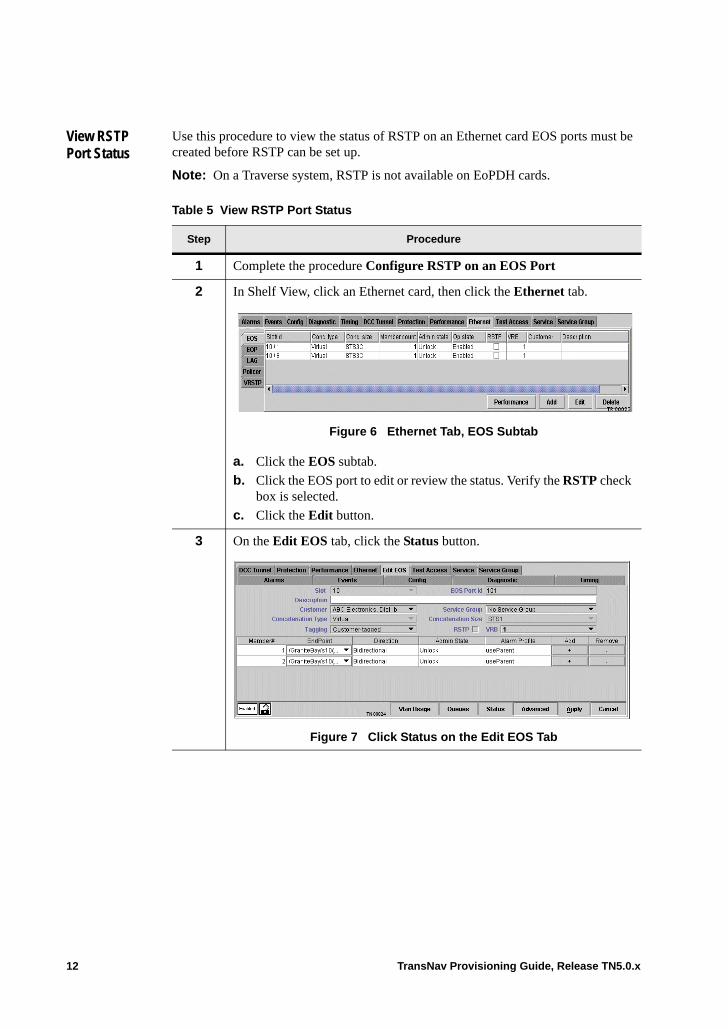
View RSTP Port Status
Use this procedure to view the status of RSTP on an Ethernet card EOS ports must be created before RSTP can be set up.
Note: On a Traverse system, RSTP is not available on EoPDH cards.
Table 5 View RSTP Port Status
Step Procedure
1 Complete the procedure Configure RSTP on an EOS Port
2 In Shelf View, click an Ethernet card, then click the Ethernet tab.
Figure 6 Ethernet Tab, EOS Subtab
a. Click the EOS subtab.
b. Click the EOS port to edit or review the status. Verify the RSTP check box is selected.
c. Click the Edit button.
3 On the Edit EOS tab, click the Status button.
Figure 7 Click Status on the Edit EOS Tab
12 TransNav Provisioning Guide, Release TN5.0.x

4 On the EOS Port Status dialog box, view the RSTP port status.
Figure 8 RSTP Parameters for EOS Port
See RSTP Port Management for explanations of these parameters.• RSTP Port State • RSTP Port Role
5 Click Refresh to retrieve the current data for the EOS port.
Click Done to close the EOS Port Status dialog box.
6 On the Edit EOS tab, click Cancel to return to the EOS list on the EOS subtab.
7 The View RSTP Port Status procedure is complete.
Table 5 View RSTP Port Status (continued)
Step Procedure
TransNav Provisioning Guide, Release TN5.0.x 13
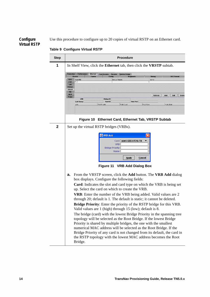
Configure Virtual RSTP
Use this procedure to configure up to 20 copies of virtual RSTP on an Ethernet card.
Table 9 Configure Virtual RSTP
Step Procedure
1 In Shelf View, click the Ethernet tab, then click the VRSTP subtab.
Figure 10 Ethernet Card, Ethernet Tab, VRSTP Subtab
2 Set up the virtual RSTP bridges (VRBs).
Figure 11 VRB Add Dialog Box
a. From the VRSTP screen, click the Add button. The VRB Add dialog box displays. Configure the following fields:Card: Indicates the slot and card type on which the VRB is being set up. Select the card on which to create the VRB.VRB: Enter the number of the VRB being added. Valid values are 2 through 20; default is 1. The default is static; it cannot be deleted.Bridge Priority: Enter the priority of the RSTP bridge for this VRB. Valid values are 1 (high) through 15 (low); default is 8.The bridge (card) with the lowest Bridge Priority in the spanning tree topology will be selected as the Root Bridge. If the lowest Bridge Priority is shared by multiple bridges, the one with the smallest numerical MAC address will be selected as the Root Bridge. If the Bridge Priority of any card is not changed from its default, the card in the RSTP topology with the lowest MAC address becomes the Root Bridge.
14 TransNav Provisioning Guide, Release TN5.0.x
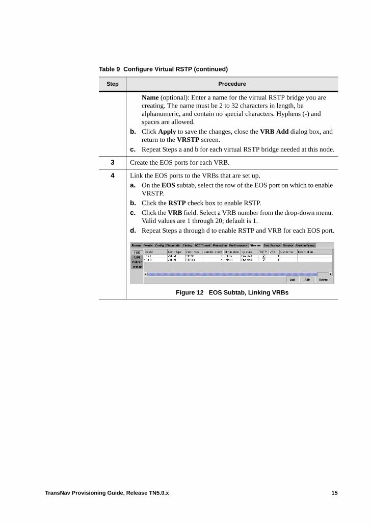
Name (optional): Enter a name for the virtual RSTP bridge you are creating. The name must be 2 to 32 characters in length, be alphanumeric, and contain no special characters. Hyphens (-) and spaces are allowed.
b. Click Apply to save the changes, close the VRB Add dialog box, and return to the VRSTP screen.
c. Repeat Steps a and b for each virtual RSTP bridge needed at this node.
3 Create the EOS ports for each VRB.
4 Link the EOS ports to the VRBs that are set up.
a. On the EOS subtab, select the row of the EOS port on which to enable VRSTP.
b. Click the RSTP check box to enable RSTP.
c. Click the VRB field. Select a VRB number from the drop-down menu. Valid values are 1 through 20; default is 1.
d. Repeat Steps a through d to enable RSTP and VRB for each EOS port.
Figure 12 EOS Subtab, Linking VRBs
Table 9 Configure Virtual RSTP (continued)
Step Procedure
TransNav Provisioning Guide, Release TN5.0.x 15

5 To view the link detail and EOS port information for a specific VRB:
a. Click the VRSTP subtab.
b. Click the VRB row for which to review the detail.
Figure 13 VRSTP Subtab, VRB Detail
c. Click Refresh. Detail information for the selected VRB appears in the fields at the bottom of the VRSTP screen. Only EOS ports with VRB enabled will display.VRB (Read-only): The VRB number assigned to this row number.Last Query (Read-only): Indicates the date and time of the last time this item was queried.Bridge ID (Read-only): Indicates the RSTP Bridge ID of this virtual RSTP bridge. Used in the RSTP protocol and displayed in the following hexidecimal format: <BridgePriority>000-MAC address>. Example: 8000-1b2000c144d8. When two cards are in a 1:1 equipment protection group, each card has a different Bridge ID, even though only one of the cards is included in the spanning tree topology at any time.Root ID (Read-only): Indicates the RSTP Root Bridge ID for this VRB.Root Port (Read-only): The RSTP Root Port ID. The EOS port on the card that provides the lowest cost to the root bridge.EOS (Read-only): The EOS Port ID assigned to this VRB.Port Priority (Read-only): The RSTP port priority. The EOS port with the lowest port priority is chosen as the root port. If several ports have the same lowest Port Priority, the port with the lowest EOS Port ID becomes the root port. Valid values are 1 through 15; default is 8.
Table 9 Configure Virtual RSTP (continued)
Step Procedure
16 TransNav Provisioning Guide, Release TN5.0.x
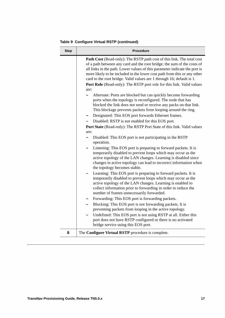
Path Cost (Read-only): The RSTP path cost of this link. The total cost of a path between any card and the root bridge; the sum of the costs of all links in the path. Lower values of this parameter indicate the port is more likely to be included in the lower cost path from this or any other card to the root bridge. Valid values are 1 through 16; default is 1.Port Role (Read-only): The RSTP port role for this link. Valid values are:– Alternate: Ports are blocked but can quickly become forwarding
ports when the topology is reconfigured. The node that has blocked the link does not send or receive any packs on that link. This blockage prevents packets from looping around the ring.
– Designated: This EOS port forwards Ethernet frames.– Disabled: RSTP is not enabled for this EOS port.Port State (Read-only): The RSTP Port State of this link. Valid values are:– Disabled: This EOS port is not participating in the RSTP
operation.– Listening: This EOS port is preparing to forward packets. It is
temporarily disabled to prevent loops which may occur as the active topology of the LAN changes. Learning is disabled since changes in active topology can lead to incorrect information when the topology becomes stable.
– Learning: This EOS port is preparing to forward packets. It is temporarily disabled to prevent loops which may occur as the active topology of the LAN changes. Learning is enabled to collect information prior to forwarding in order to reduce the number of frames unnecessarily forwarded.
– Forwarding: This EOS port is forwarding packets.– Blocking: This EOS port is not forwarding packets. It is
preventing packets from looping in the active topology.– Undefined: This EOS port is not using RSTP at all. Either this
port does not have RSTP configured or there is no activated bridge service using this EOS port.
6 The Configure Virtual RSTP procedure is complete.
Table 9 Configure Virtual RSTP (continued)
Step Procedure
TransNav Provisioning Guide, Release TN5.0.x 17

18 TransNav Provisioning Guide, Release TN5.0.x
Chapter 49 Creating Ethernet Services on Traverse
Introduction This chapter contains the following topics about creating Ethernet services on a Traverse platform:• Guidelines to Configure Ethernet Services on a Traverse Platform• NGE and EoPDH Capacity• Before You Begin• Guaranteed Data Rate and Ethernet Services• Configure Ethernet Services
Configure Ethernet cards before creating services. For information on configuring Ethernet cards, see Chapter 12—“Configuring Ethernet Equipment.” For general information on the types of Ethernet services, see Chapter 41—“Configuring Ethernet Overview.”
TransNav Provisioning Guide, Release TN5.0.x 1
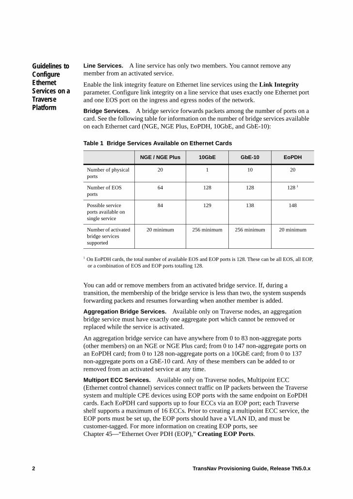
Guidelines to Configure Ethernet Services on a Traverse Platform
Line Services. A line service has only two members. You cannot remove any member from an activated service.
Enable the link integrity feature on Ethernet line services using the Link Integrity parameter. Configure link integrity on a line service that uses exactly one Ethernet port and one EOS port on the ingress and egress nodes of the network.
Bridge Services. A bridge service forwards packets among the number of ports on a card. See the following table for information on the number of bridge services available on each Ethernet card (NGE, NGE Plus, EoPDH, 10GbE, and GbE-10):
You can add or remove members from an activated bridge service. If, during a transition, the membership of the bridge service is less than two, the system suspends forwarding packets and resumes forwarding when another member is added.
Aggregation Bridge Services. Available only on Traverse nodes, an aggregation bridge service must have exactly one aggregate port which cannot be removed or replaced while the service is activated.
An aggregation bridge service can have anywhere from 0 to 83 non-aggregate ports (other members) on an NGE or NGE Plus card; from 0 to 147 non-aggregate ports on an EoPDH card; from 0 to 128 non-aggregate ports on a 10GbE card; from 0 to 137 non-aggregate ports on a GbE-10 card. Any of these members can be added to or removed from an activated service at any time.
Multiport ECC Services. Available only on Traverse nodes, Multipoint ECC (Ethernet control channel) services connect traffic on IP packets between the Traverse system and multiple CPE devices using EOP ports with the same endpoint on EoPDH cards. Each EoPDH card supports up to four ECCs via an EOP port; each Traverse shelf supports a maximum of 16 ECCs. Prior to creating a multipoint ECC service, the EOP ports must be set up, the EOP ports should have a VLAN ID, and must be customer-tagged. For more information on creating EOP ports, see Chapter 45—“Ethernet Over PDH (EOP),” Creating EOP Ports.
Table 1 Bridge Services Available on Ethernet Cards
NGE / NGE Plus 10GbE GbE-10 EoPDH
Number of physical ports
20 1 10 20
Number of EOS ports
64 128 128 128 1
1 On EoPDH cards, the total number of available EOS and EOP ports is 128. These can be all EOS, all EOP, or a combination of EOS and EOP ports totalling 128.
Possible service ports available on single service
84 129 138 148
Number of activated bridge services supported
20 minimum 256 minimum 256 minimum 20 minimum
2 TransNav Provisioning Guide, Release TN5.0.x
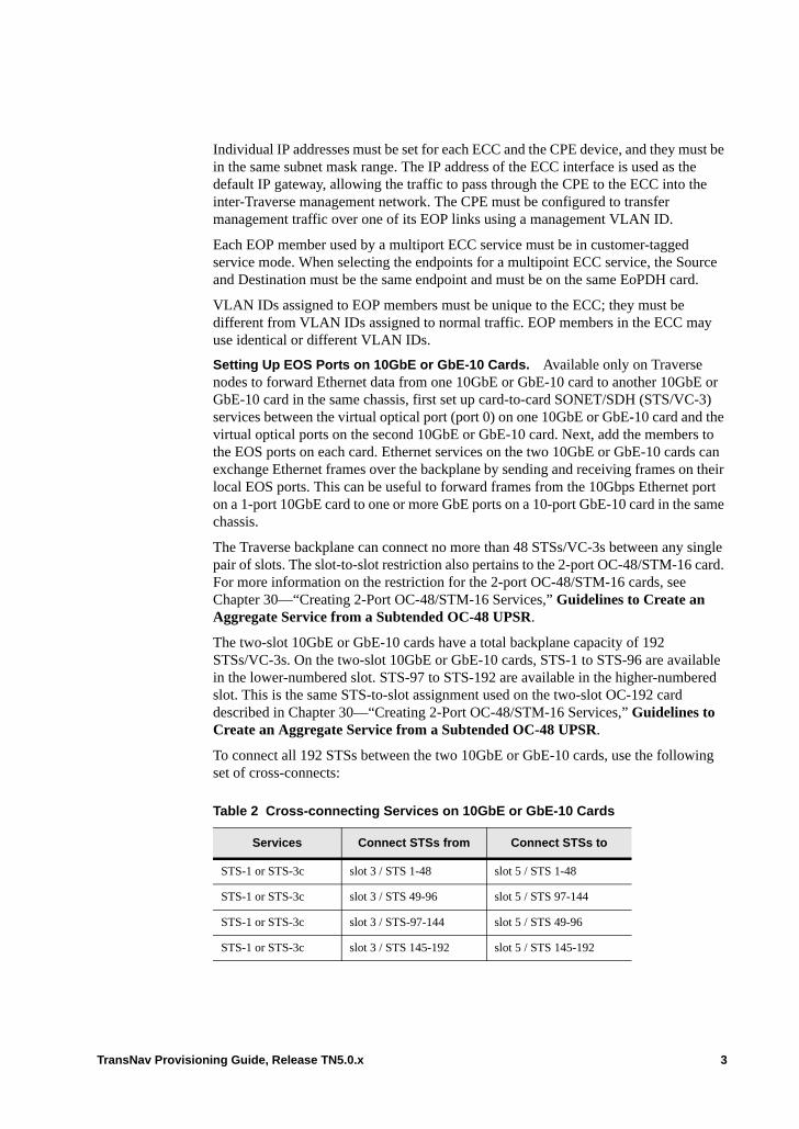
Individual IP addresses must be set for each ECC and the CPE device, and they must be in the same subnet mask range. The IP address of the ECC interface is used as the default IP gateway, allowing the traffic to pass through the CPE to the ECC into the inter-Traverse management network. The CPE must be configured to transfer management traffic over one of its EOP links using a management VLAN ID.
Each EOP member used by a multiport ECC service must be in customer-tagged service mode. When selecting the endpoints for a multipoint ECC service, the Source and Destination must be the same endpoint and must be on the same EoPDH card.
VLAN IDs assigned to EOP members must be unique to the ECC; they must be different from VLAN IDs assigned to normal traffic. EOP members in the ECC may use identical or different VLAN IDs.
Setting Up EOS Ports on 10GbE or GbE-10 Cards. Available only on Traverse nodes to forward Ethernet data from one 10GbE or GbE-10 card to another 10GbE or GbE-10 card in the same chassis, first set up card-to-card SONET/SDH (STS/VC-3) services between the virtual optical port (port 0) on one 10GbE or GbE-10 card and the virtual optical ports on the second 10GbE or GbE-10 card. Next, add the members to the EOS ports on each card. Ethernet services on the two 10GbE or GbE-10 cards can exchange Ethernet frames over the backplane by sending and receiving frames on their local EOS ports. This can be useful to forward frames from the 10Gbps Ethernet port on a 1-port 10GbE card to one or more GbE ports on a 10-port GbE-10 card in the same chassis.
The Traverse backplane can connect no more than 48 STSs/VC-3s between any single pair of slots. The slot-to-slot restriction also pertains to the 2-port OC-48/STM-16 card. For more information on the restriction for the 2-port OC-48/STM-16 cards, see Chapter 30—“Creating 2-Port OC-48/STM-16 Services,” Guidelines to Create an Aggregate Service from a Subtended OC-48 UPSR.
The two-slot 10GbE or GbE-10 cards have a total backplane capacity of 192 STSs/VC-3s. On the two-slot 10GbE or GbE-10 cards, STS-1 to STS-96 are available in the lower-numbered slot. STS-97 to STS-192 are available in the higher-numbered slot. This is the same STS-to-slot assignment used on the two-slot OC-192 card described in Chapter 30—“Creating 2-Port OC-48/STM-16 Services,” Guidelines to Create an Aggregate Service from a Subtended OC-48 UPSR.
To connect all 192 STSs between the two 10GbE or GbE-10 cards, use the following set of cross-connects:
Table 2 Cross-connecting Services on 10GbE or GbE-10 Cards
Services Connect STSs from Connect STSs to
STS-1 or STS-3c slot 3 / STS 1-48 slot 5 / STS 1-48
STS-1 or STS-3c slot 3 / STS 49-96 slot 5 / STS 97-144
STS-1 or STS-3c slot 3 / STS-97-144 slot 5 / STS 49-96
STS-1 or STS-3c slot 3 / STS 145-192 slot 5 / STS 145-192
TransNav Provisioning Guide, Release TN5.0.x 3

This cross-connect set results in 48 slot-to-slot STS connections between any pair of slots on the two-slot cards. Any equivalent set of services that does not exceed 48 slot-to-slot STS connections will work equally well.
When cross-connecting STSs between a two-slot, 1-port 10GbE card (or 10-port GbE-10 card) and a two-slot OC-192 card, the 48 slot-to-slot restriction does not apply. The OC-192 cards have specialized hardware to allow connecting more than 48 STSs per slot. You can connect any STS on a 10GbE or GbE-10 card to any STS on an OC-192 card.
4 TransNav Provisioning Guide, Release TN5.0.x
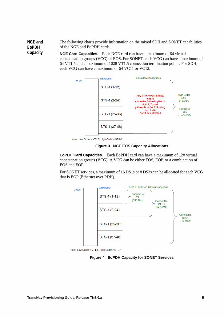
NGE and EoPDH Capacity
The following charts provide information on the mixed SDH and SONET capabilities of the NGE and EoPDH cards.
NGE Card Capacities. Each NGE card can have a maximum of 64 virtual concatenation groups (VCG) of EOS. For SONET, each VCG can have a maximum of 64 VT1.5 and a maximum of 1028 VT1.5 connection termination points. For SDH, each VCG can have a maximum of 64 VC11 or VC12.
Figure 3 NGE EOS Capacity Allocations
EoPDH Card Capacities. Each EoPDH card can have a maximum of 128 virtual concatenation groups (VCG). A VCG can be either EOS, EOP, or a combination of EOS and EOP.
For SONET services, a maximum of 16 DS1s or 8 DS3s can be allocated for each VCG that is EOP (Ethernet over PDH).
Figure 4 EoPDH Capacity for SONET Services
TransNav Provisioning Guide, Release TN5.0.x 5
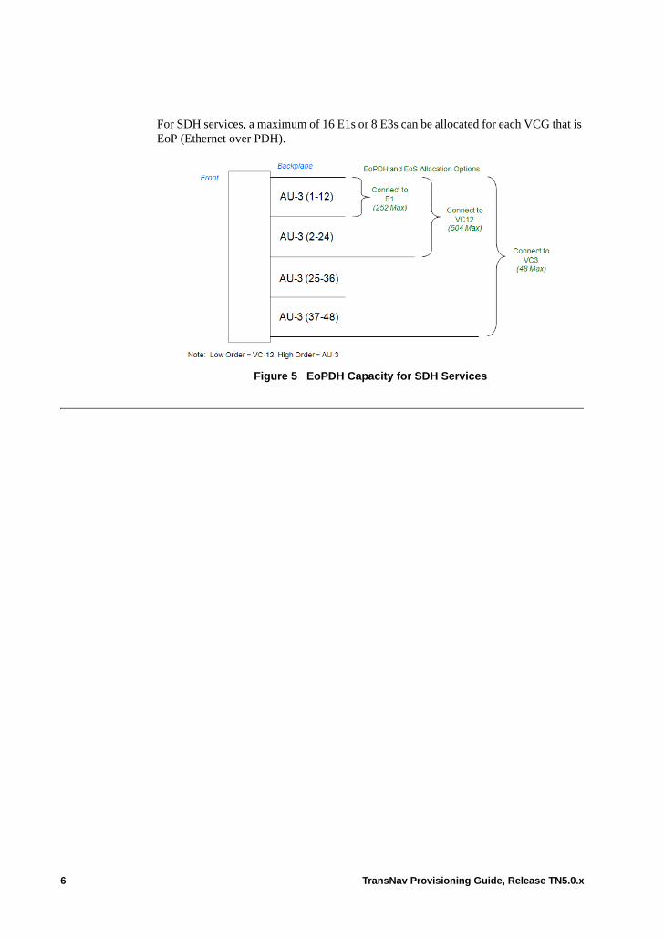
For SDH services, a maximum of 16 E1s or 8 E3s can be allocated for each VCG that is EoP (Ethernet over PDH).
Figure 5 EoPDH Capacity for SDH Services
6 TransNav Provisioning Guide, Release TN5.0.x
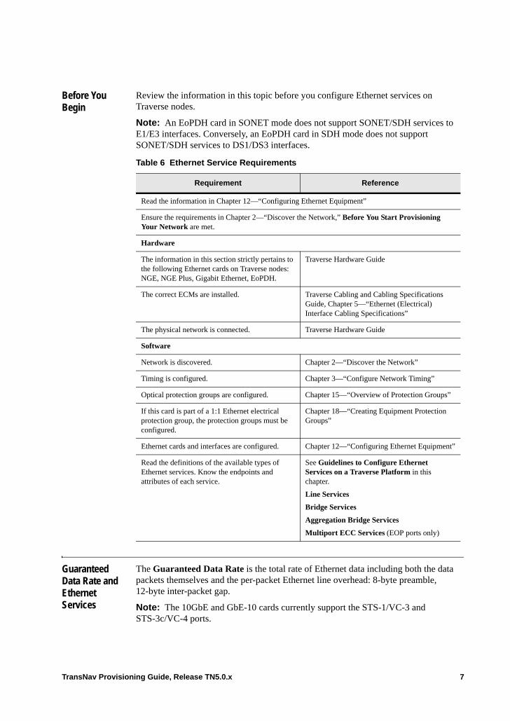
Before You Begin
Review the information in this topic before you configure Ethernet services on Traverse nodes.
Note: An EoPDH card in SONET mode does not support SONET/SDH services to E1/E3 interfaces. Conversely, an EoPDH card in SDH mode does not support SONET/SDH services to DS1/DS3 interfaces.
Guaranteed Data Rate and Ethernet Services
The Guaranteed Data Rate is the total rate of Ethernet data including both the data packets themselves and the per-packet Ethernet line overhead: 8-byte preamble, 12-byte inter-packet gap.
Note: The 10GbE and GbE-10 cards currently support the STS-1/VC-3 and STS-3c/VC-4 ports.
Table 6 Ethernet Service Requirements
Requirement Reference
Read the information in Chapter 12—“Configuring Ethernet Equipment”
Ensure the requirements in Chapter 2—“Discover the Network,” Before You Start Provisioning Your Network are met.
Hardware
The information in this section strictly pertains to the following Ethernet cards on Traverse nodes: NGE, NGE Plus, Gigabit Ethernet, EoPDH.
Traverse Hardware Guide
The correct ECMs are installed. Traverse Cabling and Cabling Specifications Guide, Chapter 5—“Ethernet (Electrical) Interface Cabling Specifications”
The physical network is connected. Traverse Hardware Guide
Software
Network is discovered. Chapter 2—“Discover the Network”
Timing is configured. Chapter 3—“Configure Network Timing”
Optical protection groups are configured. Chapter 15—“Overview of Protection Groups”
If this card is part of a 1:1 Ethernet electrical protection group, the protection groups must be configured.
Chapter 18—“Creating Equipment Protection Groups”
Ethernet cards and interfaces are configured. Chapter 12—“Configuring Ethernet Equipment”
Read the definitions of the available types of Ethernet services. Know the endpoints and attributes of each service.
See Guidelines to Configure Ethernet Services on a Traverse Platform in this chapter.
Line Services
Bridge Services
Aggregation Bridge Services
Multiport ECC Services (EOP ports only)
TransNav Provisioning Guide, Release TN5.0.x 7
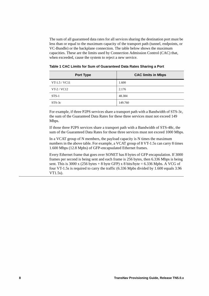
The sum of all guaranteed data rates for all services sharing the destination port must be less than or equal to the maximum capacity of the transport path (tunnel, endpoints, or VC-Bundle) or the backplane connection. The table below shows the maximum capacities. These are the limits used by Connection Admission Control (CAC) that, when exceeded, cause the system to reject a new service.
For example, if three P2PS services share a transport path with a Bandwidth of STS-3c, the sum of the Guaranteed Data Rates for these three services must not exceed 149 Mbps.
If those three P2PS services share a transport path with a Bandwidth of STS-48c, the sum of the Guaranteed Data Rates for those three services must not exceed 1000 Mbps.
In a VCAT group of N members, the payload capacity is N times the maximum numbers in the above table. For example, a VCAT group of 8 VT-1.5s can carry 8 times 1.600 Mbps (12.8 Mpbs) of GFP-encapsulated Ethernet frames.
Every Ethernet frame that goes over SONET has 8 bytes of GFP encapsulation. If 3000 frames per second is being sent and each frame is 256 bytes, then 6.336 Mbps is being sent. This is 3000 x (256 bytes + 8 byte GFP) x 8 bits/byte = 6.336 Mpbs. A VCG of four VT-1.5s is required to carry the traffic (6.336 Mpbs divided by 1.600 equals 3.96 VT1.5s).
Table 1 CAC Limits for Sum of Guaranteed Data Rates Sharing a Port
Port Type CAC limits in Mbps
VT-1.5 / VC11 1.600
VT-2 / VC12 2.176
STS-1 48.384
STS-3c 149.760
8 TransNav Provisioning Guide, Release TN5.0.x
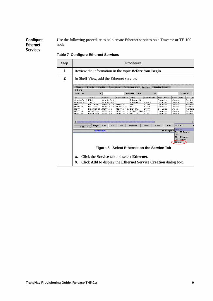
Configure Ethernet Services
Use the following procedure to help create Ethernet services on a Traverse or TE-100 node.
Table 7 Configure Ethernet Services
Step Procedure
1 Review the information in the topic Before You Begin.
2 In Shelf View, add the Ethernet service.
Figure 8 Select Ethernet on the Service Tab
a. Click the Service tab and select Ethernet.
b. Click Add to display the Ethernet Service Creation dialog box.
TransNav Provisioning Guide, Release TN5.0.x 9
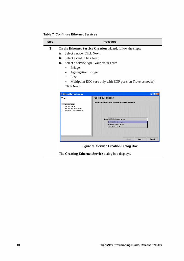
3 On the Ethernet Service Creation wizard, follow the steps:
a. Select a node. Click Next.
b. Select a card. Click Next.
c. Select a service type. Valid values are: – Bridge– Aggregation Bridge– Line– Multipoint ECC (use only with EOP ports on Traverse nodes)Click Next.
Figure 9 Service Creation Dialog Box
The Creating Ethernet Service dialog box displays.
Table 7 Configure Ethernet Services
Step Procedure
10 TransNav Provisioning Guide, Release TN5.0.x
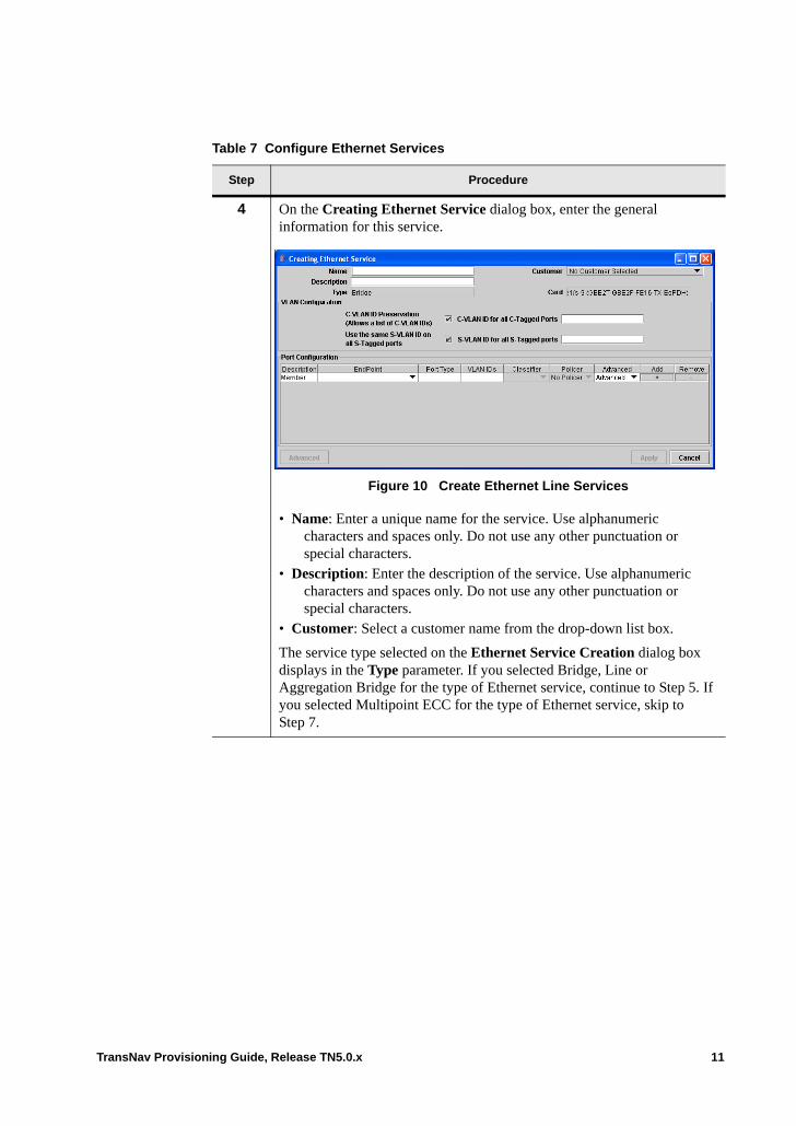
4 On the Creating Ethernet Service dialog box, enter the general information for this service.
Figure 10 Create Ethernet Line Services
• Name: Enter a unique name for the service. Use alphanumeric characters and spaces only. Do not use any other punctuation or special characters.
• Description: Enter the description of the service. Use alphanumeric characters and spaces only. Do not use any other punctuation or special characters.
• Customer: Select a customer name from the drop-down list box.
The service type selected on the Ethernet Service Creation dialog box displays in the Type parameter. If you selected Bridge, Line or Aggregation Bridge for the type of Ethernet service, continue to Step 5. If you selected Multipoint ECC for the type of Ethernet service, skip to Step 7.
Table 7 Configure Ethernet Services
Step Procedure
TransNav Provisioning Guide, Release TN5.0.x 11

5 Select the VLAN configuration type for the port types on this service. for information on VLAN tagging, see Chapter 50—“VLAN Tagging on Traverse Ethernet Services.”
Figure 11 VLAN Configuration
The valid values are:• Multiple VLAN Provisioning mode: Default for new Ethernet services.• Single VLAN ID: If this is an existing service, this value is the default in
order to preserve the existing VLAN configuration. Select one or both of the following:– C-VLAN ID Preservation: Select this check box to preserve
VLAN IDs for a range of customer-tagged port members. - C-VLAN ID for all C-Tagged Ports: Enter a set of VLAN
IDs (6, 7, 8), a range of VLAN IDs (1-27), or a combination of ranges and individual VLAN IDs (1-15, 18, 21-24, 19) to be preserved for use on this service. For example: 100, 200 indicates either 100 or 200 will be preserved, while 100-200 indicates a range from 100 to 200 will be preserved.
Note: No two activated services can use the same C-VLAN ID numbers.
Note: The Untagged and Priority tagged packets can be included as part of the C-VLAN list by using VLAN ID 0. This can be entered as VLAN IDs (0, 1-15, 18, 21-24, 19).
– Use same S-VLAN ID: Select this check box to use the same VLAN ID for all service-tagged ports. - S-VLAN ID for all S-Tagged Ports: If the Use the same
S-VLAN ID check box is selected, enter the VLAN ID to be used for all service-tagged ports on this service. If this value is not selected, you can enter different VLAN IDs for each service-tagged port member.
Table 7 Configure Ethernet Services
Step Procedure
12 TransNav Provisioning Guide, Release TN5.0.x
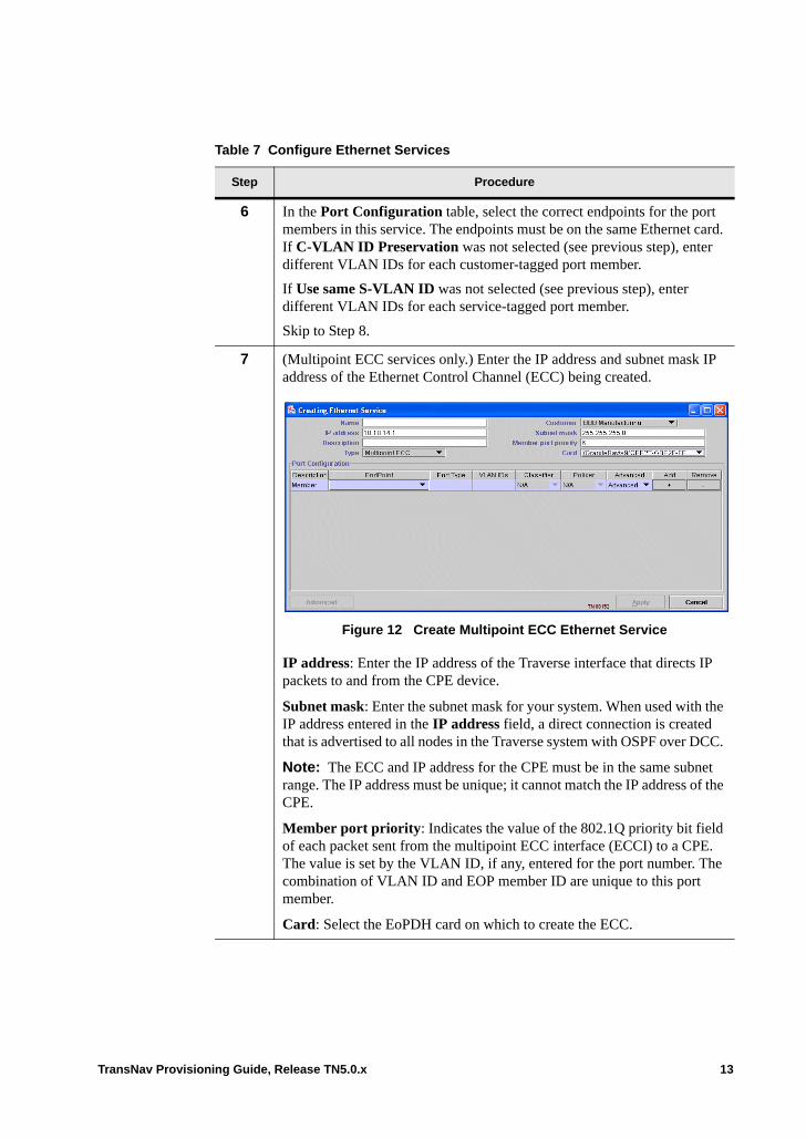
6 In the Port Configuration table, select the correct endpoints for the port members in this service. The endpoints must be on the same Ethernet card. If C-VLAN ID Preservation was not selected (see previous step), enter different VLAN IDs for each customer-tagged port member.
If Use same S-VLAN ID was not selected (see previous step), enter different VLAN IDs for each service-tagged port member.
Skip to Step 8.
7 (Multipoint ECC services only.) Enter the IP address and subnet mask IP address of the Ethernet Control Channel (ECC) being created.
Figure 12 Create Multipoint ECC Ethernet Service
IP address: Enter the IP address of the Traverse interface that directs IP packets to and from the CPE device.
Subnet mask: Enter the subnet mask for your system. When used with the IP address entered in the IP address field, a direct connection is created that is advertised to all nodes in the Traverse system with OSPF over DCC.
Note: The ECC and IP address for the CPE must be in the same subnet range. The IP address must be unique; it cannot match the IP address of the CPE.
Member port priority: Indicates the value of the 802.1Q priority bit field of each packet sent from the multipoint ECC interface (ECCI) to a CPE. The value is set by the VLAN ID, if any, entered for the port number. The combination of VLAN ID and EOP member ID are unique to this port member.
Card: Select the EoPDH card on which to create the ECC.
Table 7 Configure Ethernet Services
Step Procedure
TransNav Provisioning Guide, Release TN5.0.x 13
8 (Traverse only.) If required, assign a configured classifier or a policer to each service port.
A single policer can be assigned to multiple service ports. All flows on those service ports will be policed together and will compete for the bandwidth being policed. • Classifier: Select a classifier for this service port. See
Chapter 53—“Classifying and Prioritizing Packets” for more information on classifiers.
• Policer: Select a policer for this service port. See Chapter 54—“Policing” for more information on policers.
Table 7 Configure Ethernet Services
Step Procedure
14 TransNav Provisioning Guide, Release TN5.0.x
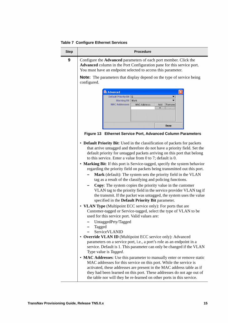
9 Configure the Advanced parameters of each port member. Click the Advanced column in the Port Configuration pane for this service port. You must have an endpoint selected to access this parameter.
Note: The parameters that display depend on the type of service being configured.
Figure 13 Ethernet Service Port, Advanced Column Parameters
• Default Priority Bit: Used in the classification of packets for packets that arrive untagged and therefore do not have a priority field. Set the default priority for untagged packets arriving on this port that belong to this service. Enter a value from 0 to 7; default is 0.
• Marking Bit: If this port is Service-tagged, specify the system behavior regarding the priority field on packets being transmitted out this port.– Mark (default): The system sets the priority field in the VLAN
tag as a result of the classifying and policing functions.– Copy: The system copies the priority value in the customer
VLAN tag to the priority field in the service provider VLAN tag if the transmit. If the packet was untagged, the system uses the value specified in the Default Priority Bit parameter.
• VLAN Type (Multipoint ECC service only): For ports that are Customer-tagged or Service-tagged, select the type of VLAN to be used for this service port. Valid values are: – UntaggedPrty/Tagged – Tagged – ServiceVLANID
• Override VLAN ID (Multipoint ECC service only): Advanced parameters on a service port, i.e., a port’s role as an endpoint in a service. Default is 1. This parameter can only be changed if the VLAN Type value is Tagged.
• MAC Addresses: Use this parameter to manually enter or remove static MAC addresses for this service on this port. While the service is activated, these addresses are present in the MAC address table as if they had been learned on this port. These addresses do not age out of the table nor will they be re-learned on other ports in this service.
Table 7 Configure Ethernet Services
Step Procedure
TransNav Provisioning Guide, Release TN5.0.x 15
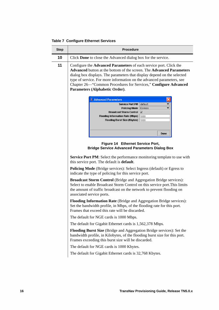
10 Click Done to close the Advanced dialog box for the service.
11 Configure the Advanced Parameters of each service port. Click the Advanced button at the bottom of the screen. The Advanced Parameters dialog box displays. The parameters that display depend on the selected type of service. For more information on the advanced parameters, see Chapter 26—“Common Procedures for Services,” Configure Advanced Parameters (Alphabetic Order).
Figure 14 Ethernet Service Port, Bridge Service Advanced Parameters Dialog Box
Service Port PM: Select the performance monitoring template to use with this service port. The default is default.
Policing Mode (Bridge services): Select Ingress (default) or Egress to indicate the type of policing for this service port.
Broadcast Storm Control (Bridge and Aggregation Bridge services): Select to enable Broadcast Storm Control on this service port.This limits the amount of traffic broadcast on the network to prevent flooding on associated service ports.
Flooding Information Rate (Bridge and Aggregation Bridge services): Set the bandwidth profile, in Mbps, of the flooding rate for this port. Frames that exceed this rate will be discarded.
The default for NGE cards is 1000 Mbps.
The default for Gigabit Ethernet cards is 1,562,378 Mbps.
Flooding Burst Size (Bridge and Aggregation Bridge services): Set the bandwidth profile, in Kilobytes, of the flooding burst size for this port. Frames exceeding this burst size will be discarded.
The default for NGE cards is 1000 Kbytes.
The default for Gigabit Ethernet cards is 32,768 Kbytes.
Table 7 Configure Ethernet Services
Step Procedure
16 TransNav Provisioning Guide, Release TN5.0.x
Link Integrity (Line services only): Monitors the status of Ethernet ports or LAGs, and the associated transport connection. Enable the link integrity feature on Ethernet line services using the Link Integrity parameter. Configure link integrity on two line services that use exactly one Ethernet port and one EOS port on the ingress and egress nodes of the network. Neither the Ethernet port nor the EOS port can be in any other activated service. Valid values are: • Disable (default): The Link Integrity feature is not used on this service.• Enabled: Enables the Link Integrity feature on this service whenever the
service is activated.
12 Click Done to close the Advanced Parameter dialog box for the service port.
13 Click Apply to create the service and return to the services list on the Service tab in the main screen.
14 The Configure Ethernet Services procedure is complete.
For Traverse, continue to Chapter 26—“Common Procedures for Services.”
For TE-100, continue to the TraverseEdge 100 User Guide, Chapter 6—“Common Procedures for Creating TE-100 Services”
Table 7 Configure Ethernet Services
Step Procedure
TransNav Provisioning Guide, Release TN5.0.x 17

18 TransNav Provisioning Guide, Release TN5.0.x
Chapter 50 VLAN Tagging on Traverse Ethernet Services
Introduction This chapter contains the following topics:• Supported Types of VLAN Tags• Ethernet Services and VLAN Tagging• VLAN Tagging Guidelines• Reserved VLAN IDs• Determining Services• All Ports in Service are Port-based• Mix of Port-based and Service-tagged Ports in a Service• All Ports in a Service are Customer-tagged• Mix of Customer-tagged and Service-tagged Ports in a Service• All Ports in a Service Are Tagged as Service-tagged• VLAN Tagging with Service OAM• View VLAN Usage
TransNav Provisioning Guide, Release TN5.0.x 1
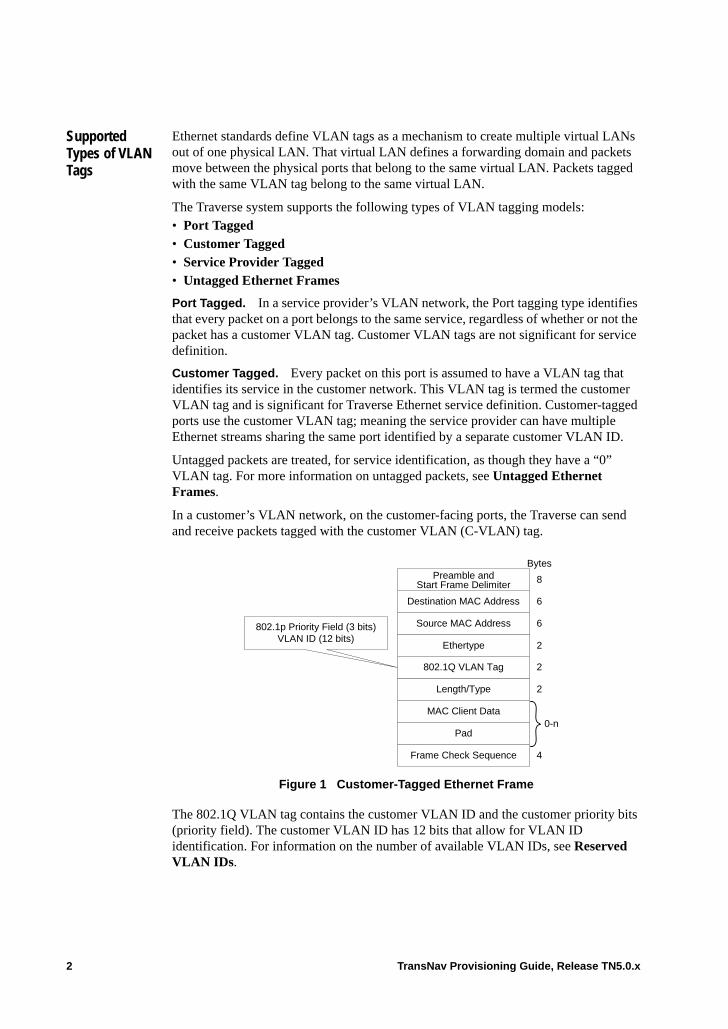
Supported Types of VLAN Tags
Ethernet standards define VLAN tags as a mechanism to create multiple virtual LANs out of one physical LAN. That virtual LAN defines a forwarding domain and packets move between the physical ports that belong to the same virtual LAN. Packets tagged with the same VLAN tag belong to the same virtual LAN.
The Traverse system supports the following types of VLAN tagging models:• Port Tagged• Customer Tagged• Service Provider Tagged• Untagged Ethernet Frames
Port Tagged. In a service provider’s VLAN network, the Port tagging type identifies that every packet on a port belongs to the same service, regardless of whether or not the packet has a customer VLAN tag. Customer VLAN tags are not significant for service definition.
Customer Tagged. Every packet on this port is assumed to have a VLAN tag that identifies its service in the customer network. This VLAN tag is termed the customer VLAN tag and is significant for Traverse Ethernet service definition. Customer-tagged ports use the customer VLAN tag; meaning the service provider can have multiple Ethernet streams sharing the same port identified by a separate customer VLAN ID.
Untagged packets are treated, for service identification, as though they have a “0” VLAN tag. For more information on untagged packets, see Untagged Ethernet Frames.
In a customer’s VLAN network, on the customer-facing ports, the Traverse can send and receive packets tagged with the customer VLAN (C-VLAN) tag.
Figure 1 Customer-Tagged Ethernet Frame
The 802.1Q VLAN tag contains the customer VLAN ID and the customer priority bits (priority field). The customer VLAN ID has 12 bits that allow for VLAN ID identification. For information on the number of available VLAN IDs, see Reserved VLAN IDs.
Length/Type
MAC Client Data
Pad
Frame Check Sequence
802.1Q VLAN Tag
Source MAC Address
Destination MAC Address
Bytes
6
6
2
2
4
802.1p Priority Field (3 bits)VLAN ID (12 bits)
0-n
Preamble andStart Frame Delimiter 8
Ethertype 2
2 TransNav Provisioning Guide, Release TN5.0.x
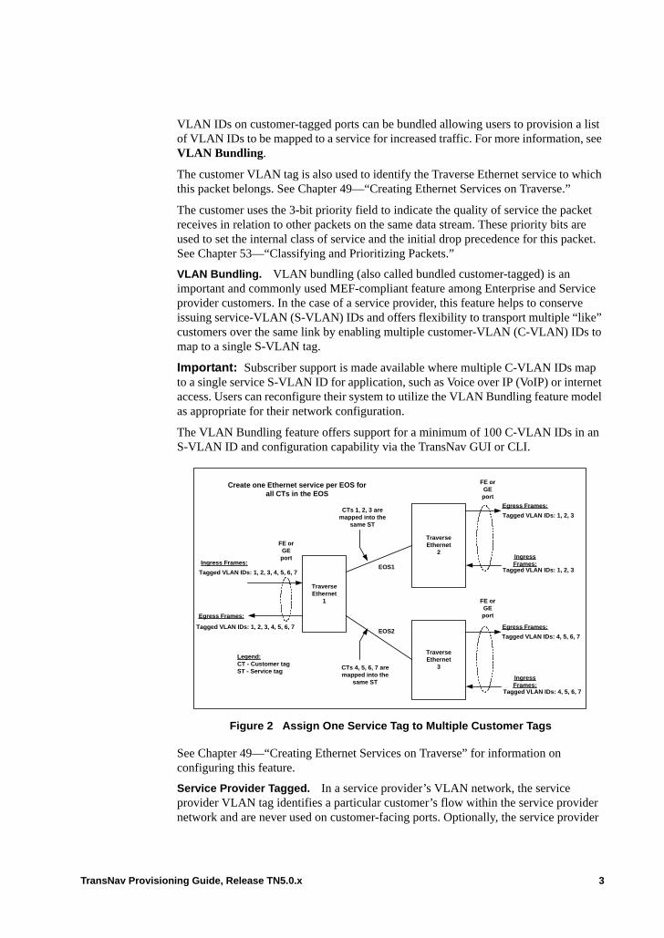
VLAN IDs on customer-tagged ports can be bundled allowing users to provision a list of VLAN IDs to be mapped to a service for increased traffic. For more information, see VLAN Bundling.
The customer VLAN tag is also used to identify the Traverse Ethernet service to which this packet belongs. See Chapter 49—“Creating Ethernet Services on Traverse.”
The customer uses the 3-bit priority field to indicate the quality of service the packet receives in relation to other packets on the same data stream. These priority bits are used to set the internal class of service and the initial drop precedence for this packet. See Chapter 53—“Classifying and Prioritizing Packets.”
VLAN Bundling. VLAN bundling (also called bundled customer-tagged) is an important and commonly used MEF-compliant feature among Enterprise and Service provider customers. In the case of a service provider, this feature helps to conserve issuing service-VLAN (S-VLAN) IDs and offers flexibility to transport multiple “like” customers over the same link by enabling multiple customer-VLAN (C-VLAN) IDs to map to a single S-VLAN tag.
Important: Subscriber support is made available where multiple C-VLAN IDs map to a single service S-VLAN ID for application, such as Voice over IP (VoIP) or internet access. Users can reconfigure their system to utilize the VLAN Bundling feature model as appropriate for their network configuration.
The VLAN Bundling feature offers support for a minimum of 100 C-VLAN IDs in an S-VLAN ID and configuration capability via the TransNav GUI or CLI.
Figure 2 Assign One Service Tag to Multiple Customer Tags
See Chapter 49—“Creating Ethernet Services on Traverse” for information on configuring this feature.
Service Provider Tagged. In a service provider’s VLAN network, the service provider VLAN tag identifies a particular customer’s flow within the service provider network and are never used on customer-facing ports. Optionally, the service provider
TraverseEthernet
1
TraverseEthernet
2
TraverseEthernet
3
Ingress Frames:
Tagged VLAN IDs: 1, 2, 3, 4, 5, 6, 7
Tagged VLAN IDs: 1, 2, 3, 4, 5, 6, 7
Egress Frames:
FE orGEport
Legend:CT - Customer tagST - Service tag
CTs 4, 5, 6, 7 aremapped into the
same ST
CTs 1, 2, 3 aremapped into the
same ST
EOS2
EOS1
Create one Ethernet service per EOS forall CTs in the EOS
Egress Frames:
Tagged VLAN IDs: 1, 2, 3
IngressFrames:
Tagged VLAN IDs: 1, 2, 3
Egress Frames:
Tagged VLAN IDs: 4, 5, 6, 7
IngressFrames:
Tagged VLAN IDs: 4, 5, 6, 7
FE orGEport
FE orGEport
TransNav Provisioning Guide, Release TN5.0.x 3
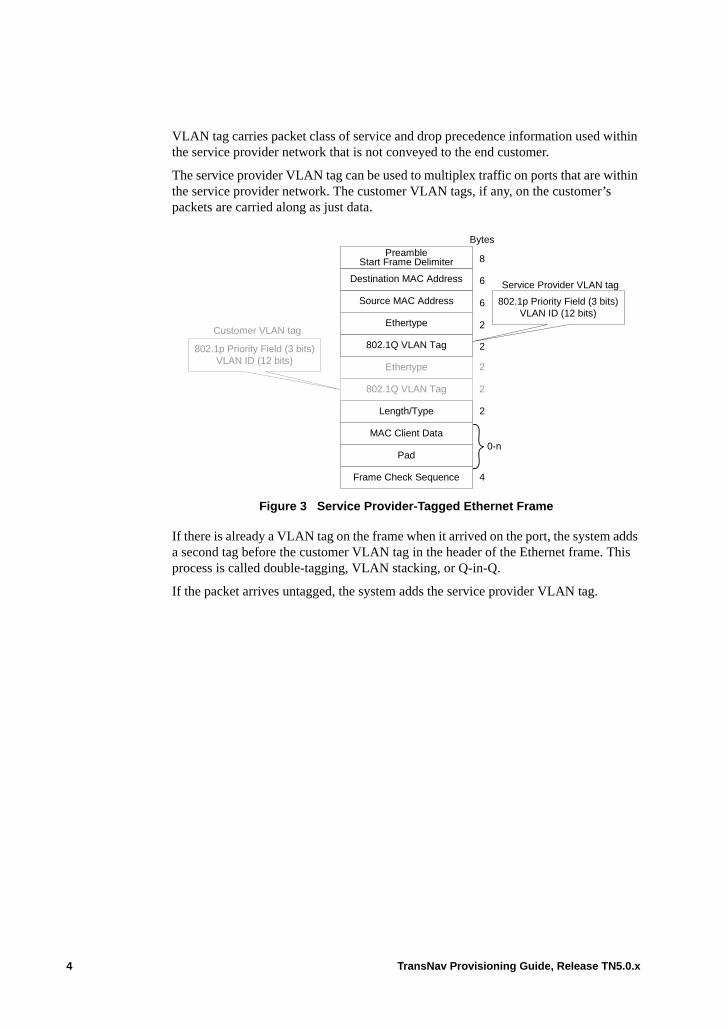
VLAN tag carries packet class of service and drop precedence information used within the service provider network that is not conveyed to the end customer.
The service provider VLAN tag can be used to multiplex traffic on ports that are within the service provider network. The customer VLAN tags, if any, on the customer’s packets are carried along as just data.
Figure 3 Service Provider-Tagged Ethernet Frame
If there is already a VLAN tag on the frame when it arrived on the port, the system adds a second tag before the customer VLAN tag in the header of the Ethernet frame. This process is called double-tagging, VLAN stacking, or Q-in-Q.
If the packet arrives untagged, the system adds the service provider VLAN tag.
Length/Type
MAC Client Data
Pad
Frame Check Sequence
802.1Q VLAN Tag
Ethertype
2
2
2
2
4
Source MAC Address
Destination MAC Address
Bytes
6
6
802.1Q VLAN Tag802.1p Priority Field (3 bits)VLAN ID (12 bits)
Service Provider VLAN tag
Customer VLAN tag
0-n
PreambleStart Frame Delimiter 8
Ethertype 2
802.1p Priority Field (3 bits)VLAN ID (12 bits)
4 TransNav Provisioning Guide, Release TN5.0.x
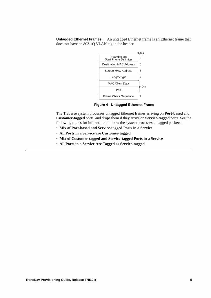
Untagged Ethernet Frames . An untagged Ethernet frame is an Ethernet frame that does not have an 802.1Q VLAN tag in the header.
Figure 4 Untagged Ethernet Frame
The Traverse system processes untagged Ethernet frames arriving on Port-based and Customer-tagged ports, and drops them if they arrive on Service-tagged ports. See the following topics for information on how the system processes untagged packets:• Mix of Port-based and Service-tagged Ports in a Service• All Ports in a Service are Customer-tagged• Mix of Customer-tagged and Service-tagged Ports in a Service• All Ports in a Service Are Tagged as Service-tagged
MAC Client Data
Pad
Frame Check Sequence
Length/Type
Source MAC Address
Destination MAC Address
Bytes
6
6
2
0-n
4
Preamble andStart Frame Delimiter 8
TransNav Provisioning Guide, Release TN5.0.x 5
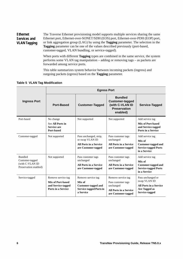
Ethernet Services and VLAN Tagging
The Traverse Ethernet provisioning model supports multiple services sharing the same Ethernet port, Ethernet-over-SONET/SDH (EOS) port, Ethernet-over-PDH (EOP) port, or link aggregation group (LAG) by using the Tagging parameter. The selection in the Tagging parameter can be one of the values described previously (port-based, customer-tagged, VLAN bundling, or service-tagged).
When ports with different Tagging types are combined in the same service, the system performs some VLAN tag manipulation – adding or removing tags – as packets are forwarded among service ports.
This table summarizes system behavior between incoming packets (ingress) and outgoing packets (egress) based on the Tagging parameter.
Table 5 VLAN Tag Modification
Ingress Port
Egress Port
Port-Based Customer-Tagged
Bundled Customer-tagged(with C-VLAN ID
Preservation enabled)
Service-Tagged
Port-based No change
See All Ports in Service are Port-based
Not supported Not supported Add service tag
Mix of Port-based and Service-tagged Ports in a Service
Customer-tagged Not supported Pass unchanged, strip, or swap VLAN ID
All Ports in a Service are Customer-tagged
Pass customer tags unchanged
All Ports in a Service are Customer-tagged
Add service tag
Mix of Customer-tagged and Service-tagged Ports in a Service
Bundled Customer-tagged(with C-VLAN ID Preservation enabled)
Not supported Pass customer tags unchanged
All Ports in a Service are Customer-tagged
Pass customer tags unchanged
All Ports in a Service are Customer-tagged
Add service tag
Mix of Customer-tagged and Service-tagged Ports in a Service
Service-tagged Remove service tag
Mix of Port-based and Service-tagged Ports in a Service
Remove service tag
Mix of Customer-tagged and Service-tagged Ports in a Service
Remove service tag
Pass customer tags unchanged
All Ports in a Service are Customer-tagged
Pass unchanged or swap VLAN ID
All Ports in a Service Are Tagged as Service-tagged
6 TransNav Provisioning Guide, Release TN5.0.x
VLAN Tagging Guidelines
You cannot change the Tagging parameter of a port if one or more services are activated on that port.
An Ethernet service cannot have a mix of Customer-tagged and Port-based ports in the same service. You cannot add a port to an activated Ethernet service if adding that port results in a mix of Customer-tagged and Port-based ports in that service.
An Ethernet service can have a mix of Service-tagged ports and either other type of tagged port.
A port using Port-based tagging can only have one Ethernet service using that port.
A port using Customer-tagged or Service-tagged tagging can have more than one Ethernet service using that port.
No two activated services can use the same C-VLAN ID on the same Customer-tagged port.
A port using Customer-tagged tagging can have one service that allows un-tagged or priority-tagged packets, thus allowing the system to know which service to associate the un-tagged or priority-tagged packets. Priority-tagged packets are tagged with a priority tag that has a VLAN ID of 0 and a specific value of priority bits.
For a given port, a VLAN ID can only be used for one service. The same VLAN ID can be used on different ports, either in the same service or in a different service. For example, if each of 10 ports are in 100 different services that is 1,000 service ports using 1,000 port-VLAN IDs (one port-VLAN ID for every tagged port in any activated service).
On Traverse nodes, NGE, NGE Plus, and EoPDH cards support any number of concurrent port-VLAN IDs up to 3,000. The 10GbE and GbE-10 cards support any number of concurrent port-VLAN IDs up to 32,768.
Reserved VLAN IDs
The valid range of configurable VLAN IDs for Ethernet services is from 1 to 4056.
The system reserves VLAN IDs 4057 to 4089 for system use. VLAN IDs 4090 to 4094 are used by the system to communicate between system cards. VLAN ID 4095 is used by the system for RSTP BPDUs.
A value of 0 (zero) indicates an untagged packet.
TransNav Provisioning Guide, Release TN5.0.x 7
Determining Services
For each Customer-tagged, Bundled Customer-tagged, and Service-tagged port in a service, it is necessary to specify which VLAN ID(s) on that port is (are) associated with which service. The system directs packets on the port with the VLAN ID to the service and ensures that packets sent by the service on the port have an associated VLAN ID.
Important: If this is an existing service created before release TR3.2, the Single VLAN ID value is set by default to preserve the existing VLAN configuration. Otherwise, the user can (but is not required to) manually change from single to multiple VLAN Provisioning mode regardless of the service’s activation state.• Multiple VLAN Provisioning mode — Multiple C-VLAN IDs on a
Customer-tagged port map to a service. (Disabled for services that existed prior to release TR3.2 upgrade.)
Note: The Traverse system supports a mix of Ethernet services activated on a port where the new VLAN provisioning option is selected on some services that use that port, and is not selected on other services that use that port.
For Ethernet services that have Multiple VLAN ID provisioning enabled, the VLAN ID value of Tagged service ports will be zero.
The parameter group used to associate (multiple) VLAN IDs with each Customer-tagged port in a service are:
– C-VLAN ID Preservation — Preserves VLAN IDs for a range of customer-tagged port members (Enabled by default).- C-VLAN ID for all Customer-tagged Ports — Create a set of C-VLAN
IDs for bundling. The user can add or remove C-VLAN IDs without interruption on an active service. Enter a set of VLAN IDs (6, 7, 8), a range of VLAN IDs (1-27), or a combination of ranges and individual VLAN IDs (1-15, 18, 21-24, 19) to be preserved for use on this service.
Note: If a set of C-VLAN IDs are defined, the system prevents the de-selection of the C-VLAN ID Preservation parameter.
Note: The Traverse system prohibits changing the C-VLAN ID Preservation from Disabled to Enabled if 1) the service currently contains more than one C-tagged port, and 2) if different C-tagged ports are provisioned to use different C-VLAN IDs.
The parameter group used to associate S-VLAN IDs with each Service-tagged port in a service are:
– Use the same S-VLAN ID on all S-Tagged ports — Use the same VLAN ID for all Service-tagged ports (i.e., do not swap S-VLAN IDs).- S-VLAN ID for all S-Tagged Ports — Identify an S-VLAN ID.
To preserve a VLAN configuration of one C-VLAN ID per service that existed before release TR3.2, use:• Single VLAN ID—One C-VLAN ID on a port maps to a service (no bundling)
The parameter group used to associate a single VLAN ID with each Customer-tagged or Service-tagged port in a service are:
– Service VLAN ID — Advanced parameters on an Ethernet service– Override VLAN ID — Advanced parameters on a service port, i.e., a port’s
role as an endpoint in a service
8 TransNav Provisioning Guide, Release TN5.0.x
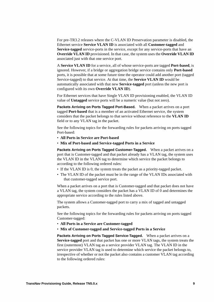
For pre-TR3.2 releases where the C-VLAN ID Preservation parameter is disabled, the Ethernet service Service VLAN ID is associated with all Customer-tagged and Service-tagged service-ports in the service, except for any service-ports that have an Override VLAN ID provisioned. In that case, the system uses the Override VLAN ID associated just with that one service port.
A Service VLAN ID for a service, all of whose service-ports are tagged Port-based, is ignored. However, if a bridge or aggregation bridge service contains only Port-based ports, it is possible that at some future time the operator could add another port (tagged Service-tagged) to that service. At that time, the Service VLAN ID would be automatically associated with that new Service-tagged port (unless the new port is configured with its own Override VLAN ID).
For Ethernet services that have Single VLAN ID provisioning enabled, the VLAN ID value of Untagged service ports will be a numeric value (but not zero).
Packets Arriving on Ports Tagged Port-Based. When a packet arrives on a port tagged Port-based that is a member of an activated Ethernet service, the system considers that the packet belongs to that service without reference to the VLAN ID field or to any VLAN tag in the packet.
See the following topics for the forwarding rules for packets arriving on ports tagged Port-based:• All Ports in Service are Port-based• Mix of Port-based and Service-tagged Ports in a Service
Packets Arriving on Ports Tagged Customer-Tagged. When a packet arrives on a port that is Customer-tagged and that packet already has a VLAN tag, the system uses the VLAN ID in the VLAN tag to determine which service the packet belongs to according to the following ordered rules:• If the VLAN ID is 0, the system treats the packet as a priority-tagged packet. • The VLAN ID of the packet must be in the range of the VLAN IDs associated with
that customer-tagged service port.
When a packet arrives on a port that is Customer-tagged and that packet does not have a VLAN tag, the system considers the packet has a VLAN ID of 0 and determines the appropriate service according to the rules listed above.
The system allows a Customer-tagged port to carry a mix of tagged and untagged packets.
See the following topics for the forwarding rules for packets arriving on ports tagged Customer-tagged:• All Ports in a Service are Customer-tagged• Mix of Customer-tagged and Service-tagged Ports in a Service
Packets Arriving on Ports Tagged Service-Tagged. When a packet arrives on a Service-tagged port and that packet has one or more VLAN tags, the system treats the first (outermost) VLAN tag as a service provider VLAN tag. The VLAN ID in the service provider VLAN tag is used to determine which service the packet belongs to, irrespective of whether or not the packet also contains a customer VLAN tag according to the following ordered rules:
TransNav Provisioning Guide, Release TN5.0.x 9
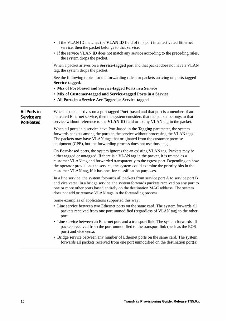
• If the VLAN ID matches the VLAN ID field of this port in an activated Ethernet service, then the packet belongs to that service.
• If the service VLAN ID does not match any service according to the preceding rules, the system drops the packet.
When a packet arrives on a Service-tagged port and that packet does not have a VLAN tag, the system drops the packet.
See the following topics for the forwarding rules for packets arriving on ports tagged Service-tagged:• Mix of Port-based and Service-tagged Ports in a Service• Mix of Customer-tagged and Service-tagged Ports in a Service• All Ports in a Service Are Tagged as Service-tagged
All Ports in Service are Port-based
When a packet arrives on a port tagged Port-based and that port is a member of an activated Ethernet service, then the system considers that the packet belongs to that service without reference to the VLAN ID field or to any VLAN tag in the packet.
When all ports in a service have Port-based in the Tagging parameter, the system forwards packets among the ports in the service without processing the VLAN tags. The packets may have VLAN tags that originated from the customer premise equipment (CPE), but the forwarding process does not use those tags.
On Port-based ports, the system ignores the an existing VLAN tag. Packets may be either tagged or untagged. If there is a VLAN tag in the packet, it is treated as a customer VLAN tag and forwarded transparently to the egress port. Depending on how the operator provisions the service, the system could examine the priority bits in the customer VLAN tag, if it has one, for classification purposes.
In a line service, the system forwards all packets from service port A to service port B and vice versa. In a bridge service, the system forwards packets received on any port to one or more other ports based entirely on the destination MAC address. The system does not add or remove VLAN tags in the forwarding process.
Some examples of applications supported this way: • Line service between two Ethernet ports on the same card. The system forwards all
packets received from one port unmodified (regardless of VLAN tag) to the other port.
• Line service between an Ethernet port and a transport link. The system forwards all packets received from the port unmodified to the transport link (such as the EOS port) and vice versa.
• Bridge service between any number of Ethernet ports on the same card. The system forwards all packets received from one port unmodified on the destination port(s).
10 TransNav Provisioning Guide, Release TN5.0.x
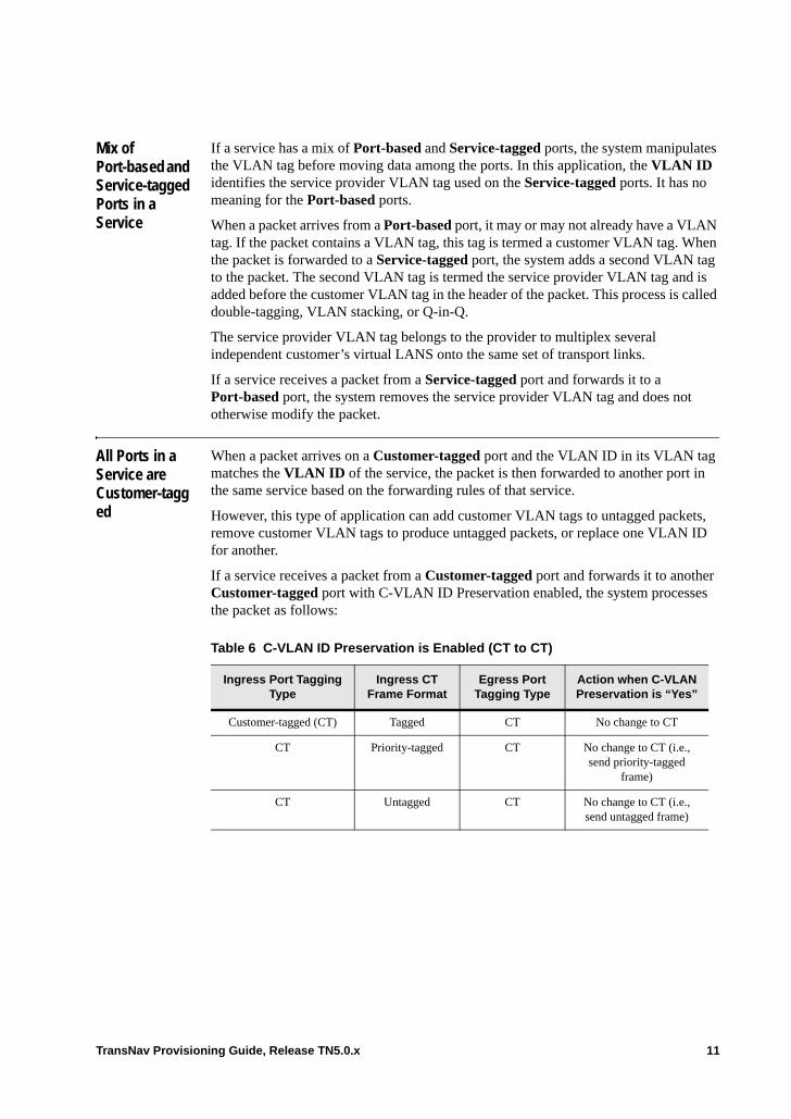
Mix of Port-based and Service-tagged Ports in a Service
If a service has a mix of Port-based and Service-tagged ports, the system manipulates the VLAN tag before moving data among the ports. In this application, the VLAN ID identifies the service provider VLAN tag used on the Service-tagged ports. It has no meaning for the Port-based ports.
When a packet arrives from a Port-based port, it may or may not already have a VLAN tag. If the packet contains a VLAN tag, this tag is termed a customer VLAN tag. When the packet is forwarded to a Service-tagged port, the system adds a second VLAN tag to the packet. The second VLAN tag is termed the service provider VLAN tag and is added before the customer VLAN tag in the header of the packet. This process is called double-tagging, VLAN stacking, or Q-in-Q.
The service provider VLAN tag belongs to the provider to multiplex several independent customer’s virtual LANS onto the same set of transport links.
If a service receives a packet from a Service-tagged port and forwards it to a Port-based port, the system removes the service provider VLAN tag and does not otherwise modify the packet.
All Ports in a Service are Customer-tagged
When a packet arrives on a Customer-tagged port and the VLAN ID in its VLAN tag matches the VLAN ID of the service, the packet is then forwarded to another port in the same service based on the forwarding rules of that service.
However, this type of application can add customer VLAN tags to untagged packets, remove customer VLAN tags to produce untagged packets, or replace one VLAN ID for another.
If a service receives a packet from a Customer-tagged port and forwards it to another Customer-tagged port with C-VLAN ID Preservation enabled, the system processes the packet as follows:
Table 6 C-VLAN ID Preservation is Enabled (CT to CT)
Ingress Port Tagging Type
Ingress CT Frame Format
Egress Port Tagging Type
Action when C-VLAN Preservation is “Yes”
Customer-tagged (CT) Tagged CT No change to CT
CT Priority-tagged CT No change to CT (i.e., send priority-tagged
frame)
CT Untagged CT No change to CT (i.e., send untagged frame)
TransNav Provisioning Guide, Release TN5.0.x 11
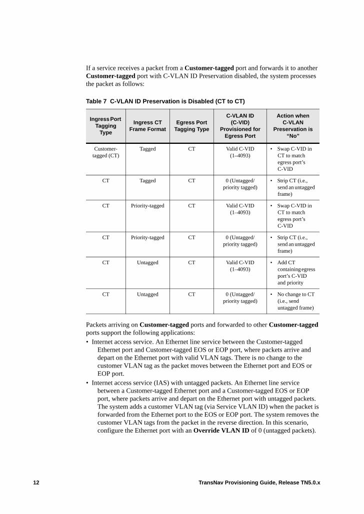
If a service receives a packet from a Customer-tagged port and forwards it to another Customer-tagged port with C-VLAN ID Preservation disabled, the system processes the packet as follows:
Packets arriving on Customer-tagged ports and forwarded to other Customer-tagged ports support the following applications:• Internet access service. An Ethernet line service between the Customer-tagged
Ethernet port and Customer-tagged EOS or EOP port, where packets arrive and depart on the Ethernet port with valid VLAN tags. There is no change to the customer VLAN tag as the packet moves between the Ethernet port and EOS or EOP port.
• Internet access service (IAS) with untagged packets. An Ethernet line service between a Customer-tagged Ethernet port and a Customer-tagged EOS or EOP port, where packets arrive and depart on the Ethernet port with untagged packets. The system adds a customer VLAN tag (via Service VLAN ID) when the packet is forwarded from the Ethernet port to the EOS or EOP port. The system removes the customer VLAN tags from the packet in the reverse direction. In this scenario, configure the Ethernet port with an Override VLAN ID of 0 (untagged packets).
Table 7 C-VLAN ID Preservation is Disabled (CT to CT)
Ingress Port Tagging
Type
Ingress CT Frame Format
Egress Port Tagging Type
C-VLAN ID (C-VID)
Provisioned for Egress Port
Action when C-VLAN
Preservation is “No”
Customer-tagged (CT)
Tagged CT Valid C-VID (1–4093)
• Swap C-VID in CT to match egress port’s C-VID
CT Tagged CT 0 (Untagged/priority tagged)
• Strip CT (i.e., send an untagged frame)
CT Priority-tagged CT Valid C-VID (1–4093)
• Swap C-VID in CT to match egress port’s C-VID
CT Priority-tagged CT 0 (Untagged/priority tagged)
• Strip CT (i.e., send an untagged frame)
CT Untagged CT Valid C-VID (1–4093)
• Add CT containing egress port’s C-VID and priority
CT Untagged CT 0 (Untagged/priority tagged)
• No change to CT (i.e., send untagged frame)
12 TransNav Provisioning Guide, Release TN5.0.x
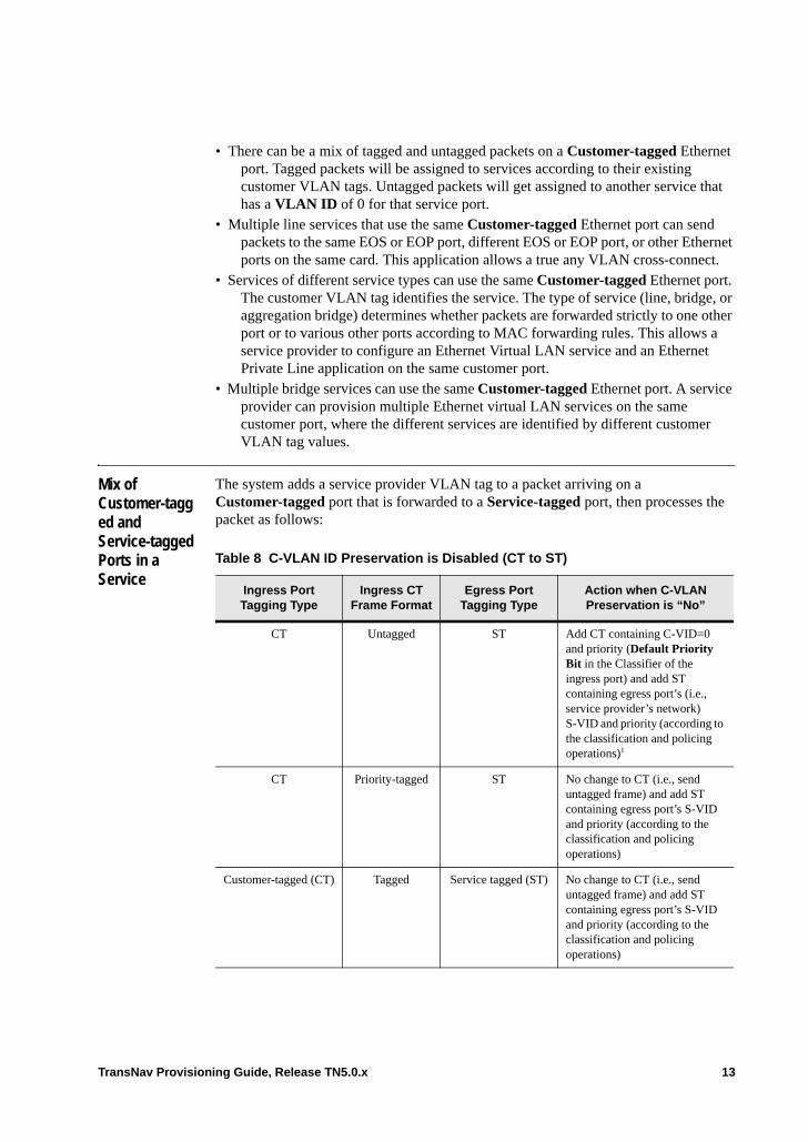
• There can be a mix of tagged and untagged packets on a Customer-tagged Ethernet port. Tagged packets will be assigned to services according to their existing customer VLAN tags. Untagged packets will get assigned to another service that has a VLAN ID of 0 for that service port.
• Multiple line services that use the same Customer-tagged Ethernet port can send packets to the same EOS or EOP port, different EOS or EOP port, or other Ethernet ports on the same card. This application allows a true any VLAN cross-connect.
• Services of different service types can use the same Customer-tagged Ethernet port. The customer VLAN tag identifies the service. The type of service (line, bridge, or aggregation bridge) determines whether packets are forwarded strictly to one other port or to various other ports according to MAC forwarding rules. This allows a service provider to configure an Ethernet Virtual LAN service and an Ethernet Private Line application on the same customer port.
• Multiple bridge services can use the same Customer-tagged Ethernet port. A service provider can provision multiple Ethernet virtual LAN services on the same customer port, where the different services are identified by different customer VLAN tag values.
Mix of Customer-tagged and Service-tagged Ports in a Service
The system adds a service provider VLAN tag to a packet arriving on a Customer-tagged port that is forwarded to a Service-tagged port, then processes the packet as follows:
Table 8 C-VLAN ID Preservation is Disabled (CT to ST)
Ingress Port Tagging Type
Ingress CT Frame Format
Egress Port Tagging Type
Action when C-VLAN Preservation is “No”
CT Untagged ST Add CT containing C-VID=0 and priority (Default Priority Bit in the Classifier of the ingress port) and add ST containing egress port’s (i.e., service provider’s network) S-VID and priority (according to the classification and policing operations)1
CT Priority-tagged ST No change to CT (i.e., send untagged frame) and add ST containing egress port’s S-VID and priority (according to the classification and policing operations)
Customer-tagged (CT) Tagged Service tagged (ST) No change to CT (i.e., send untagged frame) and add ST containing egress port’s S-VID and priority (according to the classification and policing operations)
TransNav Provisioning Guide, Release TN5.0.x 13

1 The untagged packet changes into a customer VLAN-tagged packet before the system adds the service provider VLAN tag. The customer VLAN tag carries no customer VLAN ID, only a provisioned priority for untagged packets (what IEEE calls a “priority tagged” packet). If the eventual consumer of the service provider VLAN tag is another Ethernet card in the Traverse network, the system can process both tags. For other cases (e.g., if the eventual consumer is a non-Traverse node), the service provider must decide how to process the two tags.
14 TransNav Provisioning Guide, Release TN5.0.x
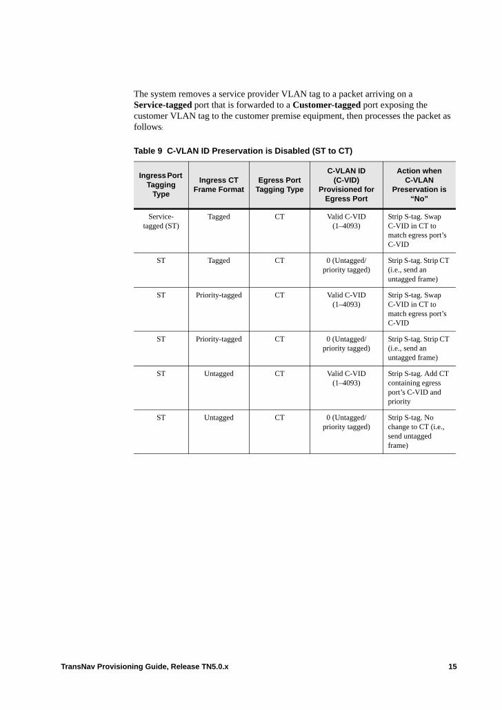
The system removes a service provider VLAN tag to a packet arriving on a Service-tagged port that is forwarded to a Customer-tagged port exposing the customer VLAN tag to the customer premise equipment, then processes the packet as follows:
Table 9 C-VLAN ID Preservation is Disabled (ST to CT)
Ingress Port Tagging
Type
Ingress CT Frame Format
Egress Port Tagging Type
C-VLAN ID (C-VID)
Provisioned for Egress Port
Action when C-VLAN
Preservation is “No”
Service-tagged (ST)
Tagged CT Valid C-VID (1–4093)
Strip S-tag. Swap C-VID in CT to match egress port’s C-VID
ST Tagged CT 0 (Untagged/priority tagged)
Strip S-tag. Strip CT (i.e., send an untagged frame)
ST Priority-tagged CT Valid C-VID (1–4093)
Strip S-tag. Swap C-VID in CT to match egress port’s C-VID
ST Priority-tagged CT 0 (Untagged/priority tagged)
Strip S-tag. Strip CT (i.e., send an untagged frame)
ST Untagged CT Valid C-VID (1–4093)
Strip S-tag. Add CT containing egress port’s C-VID and priority
ST Untagged CT 0 (Untagged/priority tagged)
Strip S-tag. No change to CT (i.e., send untagged frame)
TransNav Provisioning Guide, Release TN5.0.x 15

The system removes a service provider VLAN tag to a packet arriving on a Service-tagged port that is forwarded to a Customer-tagged port exposing the customer VLAN tag to the customer premise equipment, then processes the packet as follows:
The most common instance of this application will mix Customer-tagged Ethernet ports in a service with Service-tagged EOS or EOP ports. For example, the system adds the service provider VLAN tag to identify the Ethernet service on a shared transport service within the service provider network. At the other end of the network, the system strips the service provider VLAN tag and forwards the packet using the customer VLAN tag. Additionally, the service provider can use the service provider VLAN tag to carry policing data along with the packets in the service provider network in order to manage congestion that occurs at downstream nodes.
All Ports in a Service Are Tagged as Ser-vice-tagged
The Traverse system also supports applications in which all service ports are tagged Service-tagged. These applications include hairpinning and LO to HO switching. In a hairpinning application, all Ethernet traffic is backhauled from access nodes to an Ethernet hub that switches VLANs to other access nodes. In a LO to HO switching application, VLAN traffic is aggregated from small tunnels on an access ring to larger tunnels on a metro ring.
Packets arriving on a Service-tagged port and forwarded to another Service-tagged means that the service provider VLAN tag remains on the packet.
Specifically, if a service receives a packet from a Service-tagged port and forwards it to another Service-tagged port, the system processes the packet as follows:• If the arriving packet is tagged with appropriate VLAN ID of this service, the system
does not remove the tag (a service provider VLAN tag). The system replaces the service VLAN ID in the service provider VLAN tag in with the VLAN ID associated with the egress port. This replacement occurs whether or not the two VLAN IDs are the same. The system modifies the priority bits in the service provider VLAN tag according to the classification and policing operations.
Table 10 C-VLAN ID Preservation is Enabled (CT to ST)
Ingress Port Tagging
Type
Ingress CT Frame Format
Egress Port Tagging Type
Action when C-VLAN Preservation is “Yes”
Customer-tagged (CT)
Tagged ST No change to C-tag. Add S-tag containing egress port’s S-VLANID and priority.
CT Priority-tagged ST No change to C-tag. Add S-tag containing egress port’s S-VLANID and priority.
CT Untagged ST No change to C-tag (i.e., in this case, do not add C-tag). Add S-tag containing egress port’s S-VLANID and priority.
16 TransNav Provisioning Guide, Release TN5.0.x
Supported applications of this tagging model are as follows: • A virtual private LAN application. Packets enter the network at a Ethernet port on
Node A are switched (through Ethernet bridge services) on some intermediate Nodes B, C, and D before they leave the network at an Ethernet port on Node E. On the intermediate nodes, a packet can be forwarded from one Service-tagged port (EOS or EOP port) to another, as well as to local Ethernet ports.
• An “EtherDACS” application. Packets that enter the network at access nodes travel through small tunnels on access rings. They are aggregated into larger tunnels on metro or core rings before reaching their egress point at some head-end node. The intermediate aggregation nodes forward packets from one Service-tagged EOS or EOP port terminating a low order VCG to another EOS or EOP port terminating a high order VCG.
VLAN Tagging with Service OAM
In the Traverse system, a maintenance association (MA) is associated with a service. Within the MA, each Maintenance End Point (MEP) associated with the MA has its own unique VLAN ID called a Primary VID which usually can be determined automatically by the system based on the service and service port configuration. The Primary VID determines the inclusion and value of the customer tag (C-tag) that the MEP will place into most of its packet types.
Ethernet services that are connected from customer equipment to the network (UNIs) are typically VLAN tagged as customer-tagged or port-based; services that are network-to-network interfaces (NNIs) are typically service-tagged. On an NNI, packets can be double-tagged as customer-tagged and service-tagged.
IEEE 802.1ad introduced Provider Bridging which includes the architectural concept of ‘components’ to model the mechanism of adding and removing service tags to customer frames transported over a service provider network. The customer component bridge handles the C-tag. The service component bridge handles the S-tag.
The Primary VLAN-ID (VID) of a MEP is used to construct the VLAN tag on any Service OAM frames generated by the MEP. If the MEP’s service port has a single VID, that VID will automatically be used as the Primary VID for any MEPs that are on a service port that is tagged as service-tagged or on customer-tagged ports in a service where bundling is not supported (the value in the C-VLAN Preservation parameter is No).
If a service port accepts a range of C-VIDs, the Primary VID must be manually set to a value within the supported range of C-VIDs for any MEPs that are on a service port that is tagged as port-based or on customer-tagged ports in a service where bundling is supported (the value in the C-VLAN Preservation parameter is Yes).
VLAN tagging for maintenance associations can span both customer domains (using C-VLAN tags) and provider domains (using S-VLAN tags) in the Traverse system Service OAM model. Traverse supports the following types of maintenance association components for VLAN tagging:
Customer MA (C-MA): A C-MA monitors flows between MEPs that emulate traffic in the customer domain. These are MEPs on port-based or customer-tagged ports. The C-MA emulates customer data packets.
TransNav Provisioning Guide, Release TN5.0.x 17
Service provider MA (S-MA): A S-MA emulates the flows between MEPs that exist in the provider domain. S-MA MEPS (S-MEPs) of either direction can exist on service-tagged ports. Up S-MEPs can exist on port-based and customer-tagged ports, provided that all their traffic be limited to Service Tagged links by port configuration or more Up S-MEPs. A S-MA is compatible with third-party equipment.
The VLAN tagging type, combined with the direction (either Up or Down) defines the characteristics of the network that the MEP will monitor. Use the following guidelines to determine the type of MA to use in your network:• To monitor flows between MEPs on port-based or customer-tagged ports where the
path between any monitored pair goes entirely over a network of port-based or customer-tagged links (in a customer domain), set up a C-MA.
• To monitor flows between MEPs on port-based or customer-tagged ports where the path between any monitored pair goes entirely over a network of service-tagged links (in a provider domain), set up an S-MA.
For networks that contain a mix of links with varying tagging types, use the following guidelines: • S-MEPs on service-tagged ports will only send Service OAM frames on
service-tagged ports. Packets from S-MEPs are only defined on service-tagged ports. The packets will have the service port’s S-tag, but no C-tag.
• S-MEPs on service-tagged ports will only accept or respond to Service OAM frames sent from service-tagged ports in the same service.
• S-MEPs will not accept or receive any Service OAM frame that is double-tagged with both customer-tagged and service-tagged frames. The frame will be silently discarded. S-MEPs only carry provider-domain data; the customer-tagged frame indicates the frame came from the customer-domain, thus it is dropped.
• When an S-MEP on a PB or CT port generates a SOAM frame that enters the provider network by egressing on an ST port in the same service, that SOAM frame will be single-tagged, with the S-tag configured for the service port.
• When a C-MEP on a PB or CT port generates a SOAM frame that enters the provider network by egressing on an ST port in the same service, that SOAM frame will be double-tagged (S-tag and C-tag). The C-tag will be determined by the Primary VID as previously discussed. The S-tag will be determined by the ST port’s service port. For example, if the CT service port has a C-tag of 2, and the ST service port has an S-tag of 7, then the S-tag on the packet and the C-tag will be 2. Traverse nodes will recognize both single-tagged and double-tagged SOAM frames that it receives on ST ports. However, double-tagged SOAM frames are not defined in the standards, and other vendors might not recognize them. If it is desirable to have the SOAM frames recognized by MEPs or MIPs on ST ports on non-Traverse nodes, then the operator should use an S-MA for his PB or CT port MEPs.
18 TransNav Provisioning Guide, Release TN5.0.x
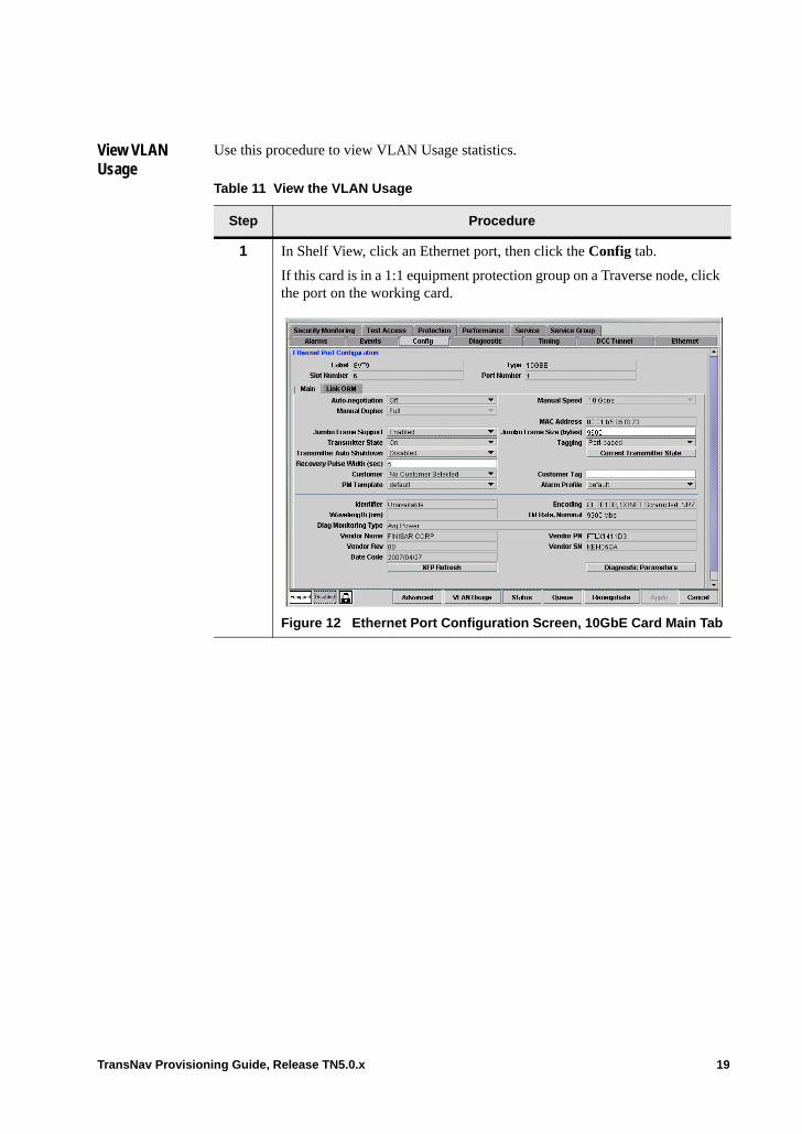
View VLAN Usage
Use this procedure to view VLAN Usage statistics.
Table 11 View the VLAN Usage
Step Procedure
1 In Shelf View, click an Ethernet port, then click the Config tab.
If this card is in a 1:1 equipment protection group on a Traverse node, click the port on the working card.
Figure 12 Ethernet Port Configuration Screen, 10GbE Card Main Tab
TransNav Provisioning Guide, Release TN5.0.x 19
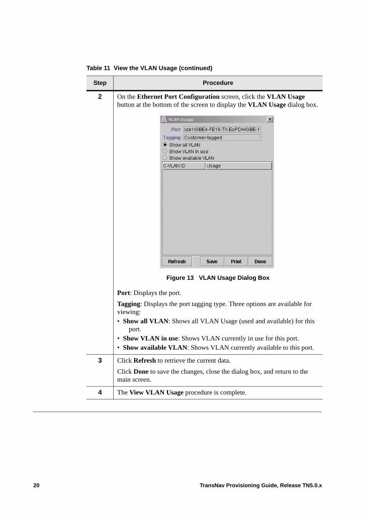
2 On the Ethernet Port Configuration screen, click the VLAN Usage button at the bottom of the screen to display the VLAN Usage dialog box.
Figure 13 VLAN Usage Dialog Box
Port: Displays the port.
Tagging: Displays the port tagging type. Three options are available for viewing:• Show all VLAN: Shows all VLAN Usage (used and available) for this
port.• Show VLAN in use: Shows VLAN currently in use for this port.• Show available VLAN: Shows VLAN currently available to this port.
3 Click Refresh to retrieve the current data.
Click Done to save the changes, close the dialog box, and return to the main screen.
4 The View VLAN Usage procedure is complete.
Table 11 View the VLAN Usage (continued)
Step Procedure
20 TransNav Provisioning Guide, Release TN5.0.x
Chapter 51 Configuring Ethernet Service OAM
Introduction Service OAM (operations, administration, maintenance) allows diagnostics to be performed across an entire end-to-end Ethernet service, called an Ethernet virtual Circuit or EVC, in the Traverse system. The diagnostics allow providers to see if data is getting through the system. The Service OAM Fault Management feature provides continuity checks, loopback and linktrace functions as defined in IEEE 802.1ag. The Service OAM Performance Monitoring feature provides methods of measuring performance such as delay, delay variation and loss as defined in ITU Y.1731 and G.8021v2.
Service OAM features are supported only on the following Traverse cards: • 10GbE• GbE-10
This chapter contains the following topics:• Understanding Service OAM• Before You Begin Configuring Service OAM• Creating MAs, MEPs, and MIPs on an Ethernet Service
– Create a Maintenance Association– Create Maintenance Endpoints (MEP)– Editing Maintenance Endpoints (MEPs)
- MEP Status Tab- Using Probes with Service OAM- Creating a Probe- Reviewing the CCM Database- Viewing Maintenance Intermediate Point (MIP) Information
– Editing MAs
TransNav Provisioning Guide, Release TN5.0.x 1
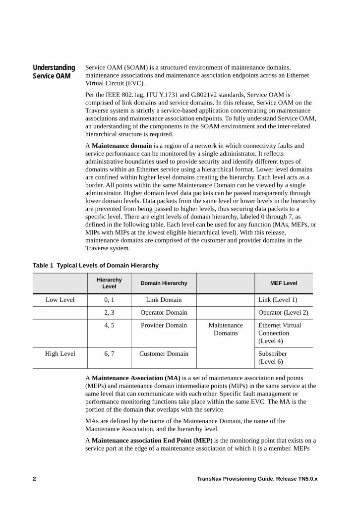
Understanding Service OAM
Service OAM (SOAM) is a structured environment of maintenance domains, maintenance associations and maintenance association endpoints across an Ethernet Virtual Circuit (EVC).
Per the IEEE 802.1ag, ITU Y.1731 and G.8021v2 standards, Service OAM is comprised of link domains and service domains. In this release, Service OAM on the Traverse system is strictly a service-based application concentrating on maintenance associations and maintenance association endpoints. To fully understand Service OAM, an understanding of the components in the SOAM environment and the inter-related hierarchical structure is required.
A Maintenance domain is a region of a network in which connectivity faults and service performance can be monitored by a single administrator. It reflects administrative boundaries used to provide security and identify different types of domains within an Ethernet service using a hierarchical format. Lower level domains are confined within higher level domains creating the hierarchy. Each level acts as a border. All points within the same Maintenance Domain can be viewed by a single administrator. Higher domain level data packets can be passed transparently through lower domain levels. Data packets from the same level or lower levels in the hierarchy are prevented from being passed to higher levels, thus securing data packets to a specific level. There are eight levels of domain hierarchy, labeled 0 through 7, as defined in the following table. Each level can be used for any function (MAs, MEPs, or MIPs with MIPs at the lowest eligible hierarchical level). With this release, maintenance domains are comprised of the customer and provider domains in the Traverse system.
A Maintenance Association (MA) is a set of maintenance association end points (MEPs) and maintenance domain intermediate points (MIPs) in the same service at the same level that can communicate with each other. Specific fault management or performance monitoring functions take place within the same EVC. The MA is the portion of the domain that overlaps with the service.
MAs are defined by the name of the Maintenance Domain, the name of the Maintenance Association, and the hierarchy level.
A Maintenance association End Point (MEP) is the monitoring point that exists on a service port at the edge of a maintenance association of which it is a member. MEPs
Table 1 Typical Levels of Domain Hierarchy
Hierarchy Level
Domain Hierarchy MEF Level
Low Level 0, 1 Link Domain Link (Level 1)
2, 3 Operator Domain Operator (Level 2)
4, 5 Provider Domain Maintenance Domains
Ethernet Virtual Connection (Level 4)
High Level 6, 7 Customer Domain Subscriber (Level 6)
2 TransNav Provisioning Guide, Release TN5.0.x

define the boundaries of a maintenance association. The MEP is used to confine SOAM packets that are defined for an MA within that MA; the MEP also prevents SOAM packets that are not defined for a specific MA from entering the MA for security purposes, such as internet attacks.
The following diagram shows an Ethernet Virtual Circuit that contains maintenance associations (MAs) and maintenance association end points (MEPs)
Figure 2 Service OAM in an Ethernet Virtual Circuit
MEPs are monitoring points at which the system collects fault management and performance monitoring functions. MEPs can exist at different MD levels at the same time, allowing them to act as a security point. MEPs from higher MD levels are transparently passed down to lower levels, however, MEPs from MD levels that are less than or equal to its level are hidden from higher level layers and are thus blocked from being passed up to a higher level.
In the following example, the Provider domain MEPs are at a Level 2 hierarchy, the MEPs at the UNI (user to network interface) are Level 3, and the EVC is Level 6. This hierarchy allows packets on the end-to-end EVC service to pass through both the UNI and the Provider domains. Packets on the UNI can pass through the Provider domain, but cannot pass through the higher level end-to-end EVC service. Packets in the Provider domain cannot pass to either the higher level UNI or EVC service; they are restricted to the Provider domain.
Figure 3 EVC Hierarchy Example
Provider Provider
UNI UNIE-NNI
Ethernet Virtual Circuit
Customer
Provider
UNI
Ethernet Virtual Circuit
Node 1 Node 2 Node 3
Level 6
Level 3
Level 2 Level 2
Level 3
TransNav Provisioning Guide, Release TN5.0.x 3
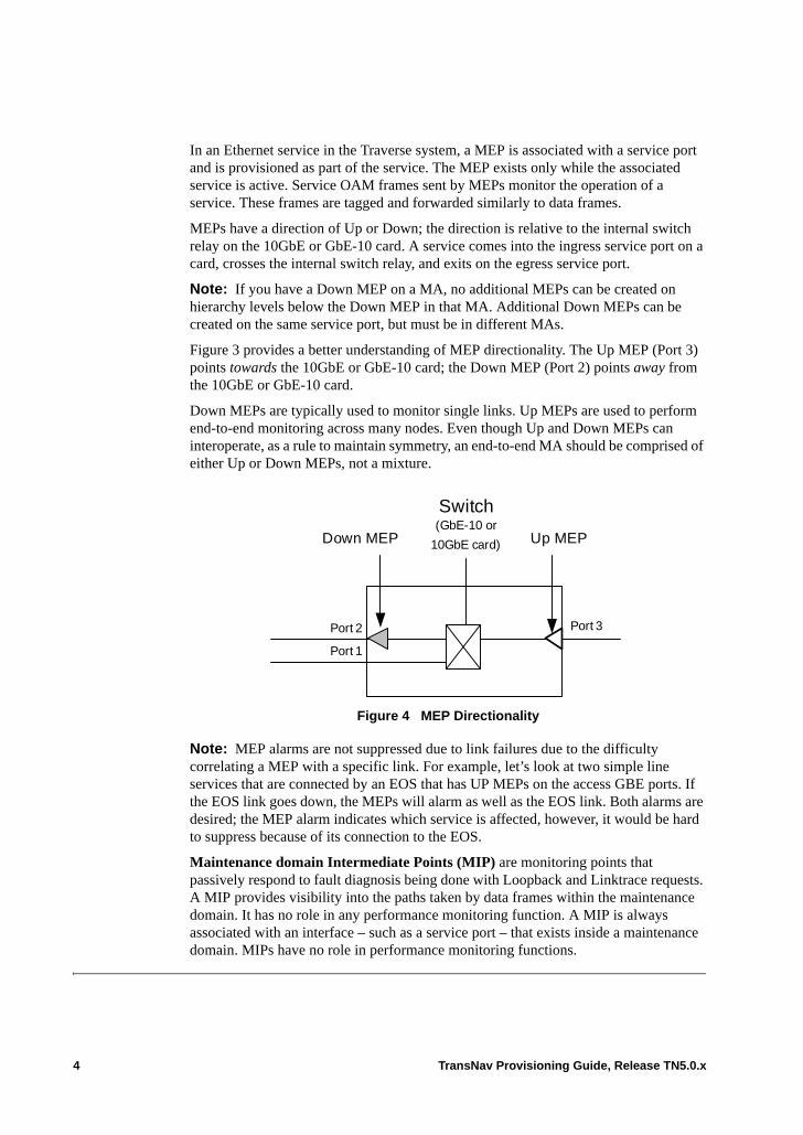
In an Ethernet service in the Traverse system, a MEP is associated with a service port and is provisioned as part of the service. The MEP exists only while the associated service is active. Service OAM frames sent by MEPs monitor the operation of a service. These frames are tagged and forwarded similarly to data frames.
MEPs have a direction of Up or Down; the direction is relative to the internal switch relay on the 10GbE or GbE-10 card. A service comes into the ingress service port on a card, crosses the internal switch relay, and exits on the egress service port.
Note: If you have a Down MEP on a MA, no additional MEPs can be created on hierarchy levels below the Down MEP in that MA. Additional Down MEPs can be created on the same service port, but must be in different MAs.
Figure 3 provides a better understanding of MEP directionality. The Up MEP (Port 3) points towards the 10GbE or GbE-10 card; the Down MEP (Port 2) points away from the 10GbE or GbE-10 card.
Down MEPs are typically used to monitor single links. Up MEPs are used to perform end-to-end monitoring across many nodes. Even though Up and Down MEPs can interoperate, as a rule to maintain symmetry, an end-to-end MA should be comprised of either Up or Down MEPs, not a mixture.
Figure 4 MEP Directionality
Note: MEP alarms are not suppressed due to link failures due to the difficulty correlating a MEP with a specific link. For example, let’s look at two simple line services that are connected by an EOS that has UP MEPs on the access GBE ports. If the EOS link goes down, the MEPs will alarm as well as the EOS link. Both alarms are desired; the MEP alarm indicates which service is affected, however, it would be hard to suppress because of its connection to the EOS.
Maintenance domain Intermediate Points (MIP) are monitoring points that passively respond to fault diagnosis being done with Loopback and Linktrace requests. A MIP provides visibility into the paths taken by data frames within the maintenance domain. It has no role in any performance monitoring function. A MIP is always associated with an interface – such as a service port – that exists inside a maintenance domain. MIPs have no role in performance monitoring functions.
Switch (GbE-10 or
10GbE card) Up MEPDown MEP
Port 1
Port 2 Port 3
4 TransNav Provisioning Guide, Release TN5.0.x

Before You Begin Configuring Service OAM
Use this procedure as a guideline to configure Service OAM on Ethernet services on GbE-10 and 10GbE cards on a Traverse system.
Note: Steps 4 through 6 can be repeated numerous times to create large multi-EVC.
Table 5 Service OAM Configuration Process
Step Procedure Reference
1 Determine the boundaries of the Maintenance Domain for the service area to be configured for Service OAM.
Understanding Service OAM
2 Plan the Service OAM configuration requirements: Maintenance Domains, Maintenance Associations, MEP requirements, MIP requirements (if any).
3 Plan how VLAN tagging will be used with MEPs.
Chapter 50—“VLAN Tagging on Traverse Ethernet Services.”
4* Create a SONET service between the two GbE-10 or 10GbE card cards on two different nodes.
Chapter 27—“Configuring SONET Services”
5 Create an Ethernet service with endpoints on a GbE-10 or 10GbE card if one is not already available.
Chapter 49—“Creating Ethernet Services on Traverse”
6 Create Maintenance Associations for the EVC.
Create a Maintenance Association
7 Create local Maintenance association End Points (MEPs) on service points at the boundaries of the Maintenance Association.
Create Maintenance Endpoints (MEP)
8 Set up VLAN tagging on MEPs. Chapter 50—“VLAN Tagging on Traverse Ethernet Services,” VLAN Tagging with Service OAM
9 To monitor performance, set up the Service OAM / Probe performance monitoring templates.
Operations and Maintenance Guide, Chapter 7—“Ethernet Performance Parameters,” Ethernet Service OAM / Probe PM Template Tab Parameters.
TransNav Provisioning Guide, Release TN5.0.x 5
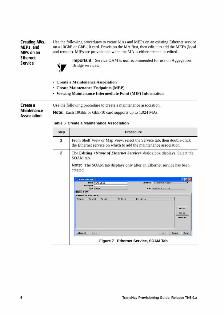
Creating MAs, MEPs, and MIPs on an Ethernet Service
Use the following procedures to create MAs and MEPs on an existing Ethernet service on a 10GbE or GbE-10 card. Provision the MA first, then edit it to add the MEPs (local and remote). MIPs are provisioned when the MA is either created or edited.
• Create a Maintenance Association• Create Maintenance Endpoints (MEP)• Viewing Maintenance Intermediate Point (MIP) Information
Create a Maintenance Association
Use the following procedure to create a maintenance association.
Note: Each 10GbE or GbE-10 card supports up to 1,024 MAs.
Important: Service OAM is not recommended for use on Aggegation Bridge services.
Table 6 Create a Maintenance Association
Step Procedure
1 From Shelf View or Map View, select the Service tab, then double-click the Ethernet service on which to add the maintenance association.
2 The Editing <Name of Ethernet Service> dialog box displays. Select the SOAM tab.
Note: The SOAM tab displays only after an Ethernet service has been created.
Figure 7 Ethernet Service, SOAM Tab
6 TransNav Provisioning Guide, Release TN5.0.x

3 Click Add MA. The Creating Maintenance Association dialog box displays.
Figure 8 Creating Maintenance Association Dialog Box
Table 6 Create a Maintenance Association (continued)
Step Procedure
TransNav Provisioning Guide, Release TN5.0.x 7
4* Set up the parameters for this MA.
In the Maintenance Association ID pane, select:• MD Level: Select the maintenance domain level for this MA. Valid
values are 0 through 7. • MD name: Enter a name for the maintenance domain. The name can be
0 to 20 characters in length, can contain alphanumeric characters and the following special characters - . _ : / # , ” (dash, period, underscore, colon, forward slash, pound sign, comma, double-quote).
Note: Force10 suggests including the MD Level number as part of the name.
• MA name: Enter a name for the maintenance association. The name can be 1 to 20 characters in length, can contain alphanumeric characters and the following special characters - . _ : / # , ” (dash, period, underscore, colon, forward slash, pound sign, comma, double-quote).
Note: Force10 suggests making the MA name match the name of the end-to-end service to easily correlate the MA to the service.
In the Maintenance Association Configuration pane, enter the following information:• Description: Enter a brief description of the maintenance association
being created.• Primary VID: (For use on Service-oriented MEPs only.) Select a
specific VLAN-ID to include in Service OAM frames. Valid values are 0-4095. This is set manually or by the system using the following rules. If a service port acepts a range of VLAN-IDs, the Primary VLAN-ID of any MEPs on that service port must be manually set. The MEPs must be on port-based VLAN-IDs or MEPs on customer-tagged ports in a service where bundling is supported (Customer VLAN Preservation is set to Yes.)The value must be within the range supported by the service port. If a service port accepts only a single VLAN-ID, the system automatically sets the Primary VLAN-ID of any MEPs on that service port to that single value. The MEPs must be on service-tagged ports, or on customer-taggped ports in a service that is not bundled (Customer VLAN Preservation is set to No).
• CCM interval: Select the interval between continuity check messages (CCM) to be used by all MEPs in the MA. Valid values are: 100-ms, 1-sec (default), 10-sec, 1-min, 10-min.
• MA Component: Indicate the component type for this MA. The valid values are:– C-MA (default): Indicates customer-tagged. The MA emulates a
customer packet and monitors the customer domain.– S-MA: Indicates service-tagged. The MA emulates pure service
Table 6 Create a Maintenance Association (continued)
Step Procedure
8 TransNav Provisioning Guide, Release TN5.0.x
traffic, is compatible with other vendors, and monitors the provider domain.
Create Maintenance Endpoints (MEP)
After the Maintenance Association has been created, add the local and remote maintenance end points (MEPs) for the MA. Each MEP must have a unique MEP ID within the global MA. MEP IDs are manually created.
• MIP Creation: Indicate if intermediate monitoring points should be created on service ports within the MA that do not have MEPs. Select one of the following values:– None (default): No intermediate monitoring points will be
created.– Default: Select to create an intermediate monitoring point. – Explicit: Select to create an intermediate monitoring point only if
the maintenance association in the next lower maintenance domain level has a Maintenance association End Point. Use this value on provider networks to protect lower domain levels from being seen by customer networks.
• Sender ID Permission: Set the value for the amount of inform ai ton that is included in the continuity check message that is sent by this MEP. Valid values are: – None (default): No sender ID information will be sent (Sender ID
TLV). – Chassis: Send only the Node ID and slot number. – ManagementAddress: Send only the Node IP Address.– All: Send the Node ID and Node IP Address.
5 Click Apply. The Editing <Name of Ethernet Service> dialog box displays.
6 The procedure Create a Maintenance Association is complete.
Table 6 Create a Maintenance Association (continued)
Step Procedure
Table 9 Create Maintenance End Points (MEP)
1 Complete the procedure Create a Maintenance Association.
If you just completed the procedure Create a Maintenance Association, skip to Step 4.
2 From Shelf View, select the Service tab, then double-click the Ethernet service that has the MA where the MEPs will be added.
The Editing <Service Name> dialog box displays.
3 Select the SOAM tab. The Editing <Service Name> dialog box displays with a list of available maintenance associations.
TransNav Provisioning Guide, Release TN5.0.x 9
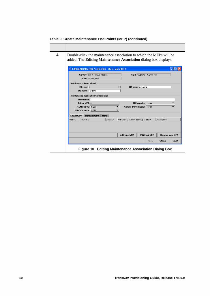
4 Double-click the maintenance association to which the MEPs will be added. The Editing Maintenance Association dialog box displays.
Figure 10 Editing Maintenance Association Dialog Box
Table 9 Create Maintenance End Points (MEP) (continued)
10 TransNav Provisioning Guide, Release TN5.0.x
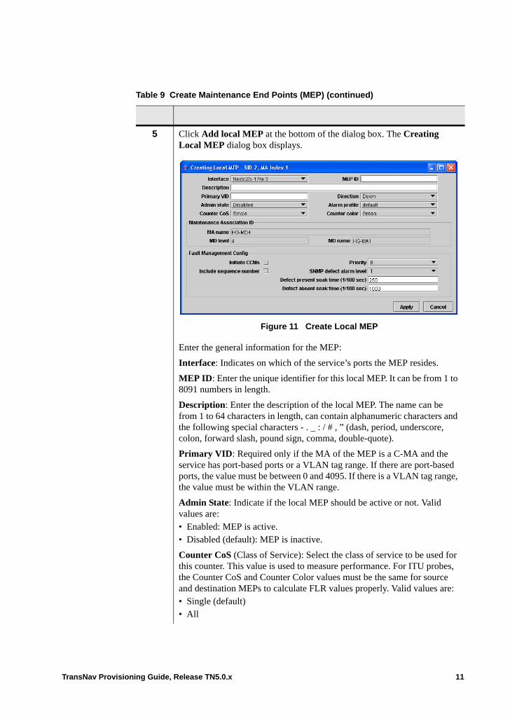
5 Click Add local MEP at the bottom of the dialog box. The Creating Local MEP dialog box displays.
Figure 11 Create Local MEP
Enter the general information for the MEP:
Interface: Indicates on which of the service’s ports the MEP resides.
MEP ID: Enter the unique identifier for this local MEP. It can be from 1 to 8091 numbers in length.
Description: Enter the description of the local MEP. The name can be from 1 to 64 characters in length, can contain alphanumeric characters and the following special characters - . _ : / # , ” (dash, period, underscore, colon, forward slash, pound sign, comma, double-quote).
Primary VID: Required only if the MA of the MEP is a C-MA and the service has port-based ports or a VLAN tag range. If there are port-based ports, the value must be between 0 and 4095. If there is a VLAN tag range, the value must be within the VLAN range.
Admin State: Indicate if the local MEP should be active or not. Valid values are:• Enabled: MEP is active.• Disabled (default): MEP is inactive.
Counter CoS (Class of Service): Select the class of service to be used for this counter. This value is used to measure performance. For ITU probes, the Counter CoS and Counter Color values must be the same for source and destination MEPs to calculate FLR values properly. Valid values are: • Single (default) • All
Table 9 Create Maintenance End Points (MEP) (continued)
TransNav Provisioning Guide, Release TN5.0.x 11
Direction: Indicate the direction that frames will be sent from the MEP. Valid values are: • Down (Default): MEP frames will be sent away from the relay (10GbE
or GbE-10 card).• Up: MEP frames will be sent towards the relay.
Alarm profile: Select the alarm profile to be used with this MEP.
Counter Color: Select the color of the MEP counter. This value is used to measure performance. For ITU probes, the Counter CoS and Counter Color values must be the same for source and destination MEPs to calculate FLR values properly. Valid values are:• Green (default)• All
6* In the Fault Management Config screen, set the following parameters:
Initiate CMMs: Select the check box to initiate continuity check messages for this MEP.
Include sequence number: Select the check box to include the sequence number.
Priority: Set the priority level of continuity check messages and linktrace messages for this MEP. Valid values are 0 through 7. Default is 0.
SNMP defect alarm level: Set the value to indicate the lowest priority defect that will generate an SNMP notification. Valid values are 1 through 6. Default is 1 (all defects are reported).
Defect present soak time (1/100 sec): Indicates the amount of time in hundredths of a second that a defect must be present before an alarm is generated. Valid values are 2.5 seconds (250) to 10.0 seconds. Default is 250 (2.5 seconds).
Defect present absent time (1/100 sec): Indicates the amount of time in hundredths of a second that a defect must be absent before an alarm is cleared. Valid values are 2.5 seconds to 10.0 seconds. Default is 1000 (10 seconds).
7 Click Apply to set the changes.
8 Create the remote MEP to allow loopback and link trace. From the Editing Maintenance Association dialog box, click the Remote MEPs tab. The Remote MEPs screen displays. Click Add remote MEP at the bottom of the screen to display the
Table 9 Create Maintenance End Points (MEP) (continued)
12 TransNav Provisioning Guide, Release TN5.0.x
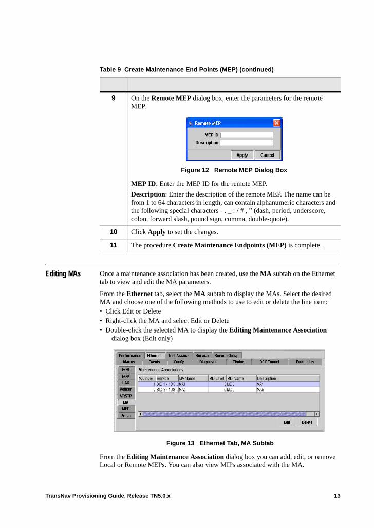
Editing MAs Once a maintenance association has been created, use the MA subtab on the Ethernet tab to view and edit the MA parameters.
From the Ethernet tab, select the MA subtab to display the MAs. Select the desired MA and choose one of the following methods to use to edit or delete the line item:• Click Edit or Delete • Right-click the MA and select Edit or Delete • Double-click the selected MA to display the Editing Maintenance Association
dialog box (Edit only)Ether
Figure 13 Ethernet Tab, MA Subtab
From the Editing Maintenance Association dialog box you can add, edit, or remove Local or Remote MEPs. You can also view MIPs associated with the MA.
9 On the Remote MEP dialog box, enter the parameters for the remote MEP.
Figure 12 Remote MEP Dialog Box
MEP ID: Enter the MEP ID for the remote MEP.
Description: Enter the description of the remote MEP. The name can be from 1 to 64 characters in length, can contain alphanumeric characters and the following special characters - . _ : / # , ” (dash, period, underscore, colon, forward slash, pound sign, comma, double-quote).
10 Click Apply to set the changes.
11 The procedure Create Maintenance Endpoints (MEP) is complete.
Table 9 Create Maintenance End Points (MEP) (continued)
TransNav Provisioning Guide, Release TN5.0.x 13
Viewing Maintenance Intermediate Point (MIP) Information
Maintenance domain intermediate points (MIPs) are monitoring points that passively respond to Fault Management loopback and link trace requests. They have no role in performance monitoring functions. MIPs provide visibility into paths taken by data frames within the maintenance domain. Operators can perform a link trace to discover MIPs along a service path and then perform a loopback to those MIPs to test connectivity. Based on information provisioned when the MA is created, MIPs are created on both ends of the service. If a MEP is created on the same level, the MIP will not display on the MIP tab.
Maintenance intermediate points are created when a maintenance association is created or edited. For information on creating MIPs, see Create a Maintenance Association, Step 4.
Note: Each service port can have only one MIP. A MIP cannot be generated below a down MEP on an MA.
Table 14 Viewing Maintenance Intermediate Point (MIP) Information
1 Complete the procedure Create a Maintenance Association.
If you just completed the procedure Create a Maintenance Association, skip to Step 3.
2 From Shelf View, select the Service tab, then double-click the Ethernet service that has the MA where the MIPs will be added.
The Editing <Service Name> dialog box displays.
3 Select the SOAM tab. The Editing <Service Name> dialog box displays with a list of available maintenance associations.
14 TransNav Provisioning Guide, Release TN5.0.x
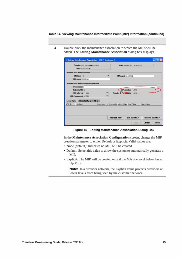
4 Double-click the maintenance association to which the MIPs will be added. The Editing Maintenance Association dialog box displays.
Figure 15 Editing Maintenance Association Dialog Box
In the Maintenance Association Configuration screen, change the MIP creation parameter to either Default or Explicit. Valid values are:• None (default): Indicates no MIP will be created. • Default: Select this value to allow the system to automatically generate a
MIP.• Explicit: The MIP will be created only if the MA one level below has an
Up MEP.
Note: In a provider network, the Explicit value protects providers at lower levels from being seen by the customer network.
Table 14 Viewing Maintenance Intermediate Point (MIP) Information (continued)
TransNav Provisioning Guide, Release TN5.0.x 15
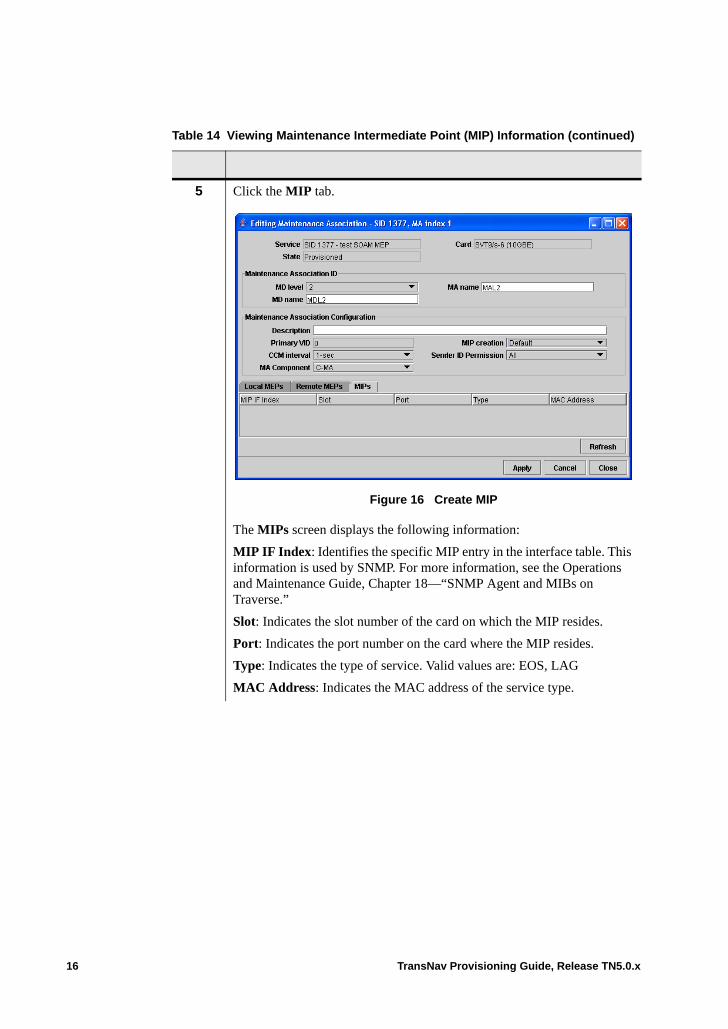
5 Click the MIP tab.
Figure 16 Create MIP
The MIPs screen displays the following information:
MIP IF Index: Identifies the specific MIP entry in the interface table. This information is used by SNMP. For more information, see the Operations and Maintenance Guide, Chapter 18—“SNMP Agent and MIBs on Traverse.”
Slot: Indicates the slot number of the card on which the MIP resides.
Port: Indicates the port number on the card where the MIP resides.
Type: Indicates the type of service. Valid values are: EOS, LAG
MAC Address: Indicates the MAC address of the service type.
Table 14 Viewing Maintenance Intermediate Point (MIP) Information (continued)
16 TransNav Provisioning Guide, Release TN5.0.x
Editing Maintenance Endpoints (MEPs)
Editing maintenance endpoints allows you to adjust fault management configurations, view the status of MEPs, view performance monitoring data for specific MEPs, and review continuity check message database entries. See the following sections for more information.
Note: Any specific fault management or performance management function, such as a loopback operation or a delay measurement, takes place within a single MA. • Fault Management Config Tab. See Create Maintenance Endpoints (MEP),
Step 6. • MEP Status Tab• Using Probes with Service OAM• Reviewing the CCM Database
6* In the Fault Management Config screen at the bottom of the dialog box, set the following parameters:
Initiate CMMs: Select the check box to initiate continuity check messages for this MEP.
Include sequence number: Select the check box to include the sequence number
Priority: Set the priority level of continuity check messages and linktrace messages for this MEP. Valid values are 0 through 7. Default is 0.
SNMP defect alarm level: Set the value to indicate the lowest priority def et that will generate an SNMP notification. Valid values are 1 through 6. Default is 1 (all defects are reported).
Defect present soak time (1/100 sec): Indicates the amount of time in hundredths of a second that a defect must be present before an alarm is generated. Valid values are 2.5 seconds (250) to 10.0 seconds. Default is 250 (2.5 seconds).
Defect present absent time (1/100 sec): Indicates the amount of time in hundredths of a second that a defect must be absent before an alarm is cleared. Valid values are 2.5 seconds to 10.0 seconds. Default is 1000 (10 seconds).
7 Click Apply to set the changes. The Editing Maintenance Association dialog box displays.
8 The procedure Viewing Maintenance Intermediate Point (MIP) Information is complete. Click Close to exit the dialog box.
Table 14 Viewing Maintenance Intermediate Point (MIP) Information (continued)
TransNav Provisioning Guide, Release TN5.0.x 17
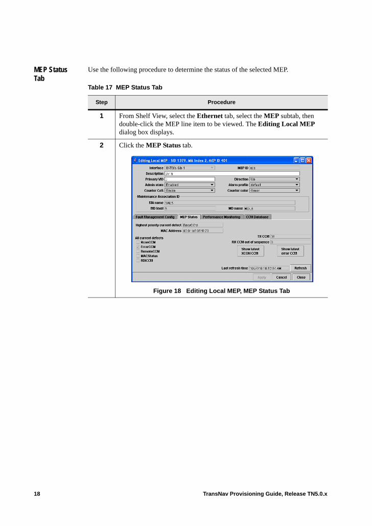
MEP Status Tab
Use the following procedure to determine the status of the selected MEP.
Table 17 MEP Status Tab
Step Procedure
1 From Shelf View, select the Ethernet tab, select the MEP subtab, then double-click the MEP line item to be viewed. The Editing Local MEP dialog box displays.
2 Click the MEP Status tab.
Figure 18 Editing Local MEP, MEP Status Tab
18 TransNav Provisioning Guide, Release TN5.0.x
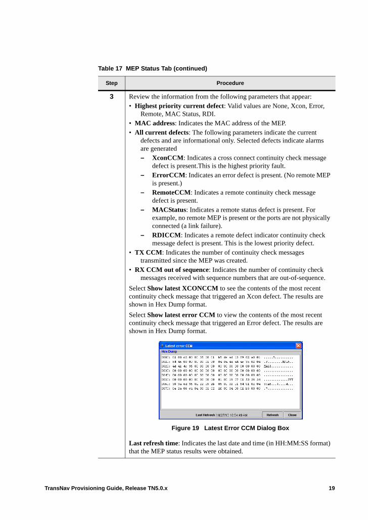
3 Review the information from the following parameters that appear: • Highest priority current defect: Valid values are None, Xcon, Error,
Remote, MAC Status, RDI. • MAC address: Indicates the MAC address of the MEP. • All current defects: The following parameters indicate the current
defects and are informational only. Selected defects indicate alarms are generated– XconCCM: Indicates a cross connect continuity check message
defect is present.This is the highest priority fault.– ErrorCCM: Indicates an error defect is present. (No remote MEP
is present.)– RemoteCCM: Indicates a remote continuity check message
defect is present. – MACStatus: Indicates a remote status defect is present. For
example, no remote MEP is present or the ports are not physically connected (a link failure).
– RDICCM: Indicates a remote defect indicator continuity check message defect is present. This is the lowest priority defect.
• TX CCM: Indicates the number of continuity check messages transmitted since the MEP was created.
• RX CCM out of sequence: Indicates the number of continuity check messages received with sequence numbers that are out-of-sequence.
Select Show latest XCONCCM to see the contents of the most recent continuity check message that triggered an Xcon defect. The results are shown in Hex Dump format.
Select Show latest error CCM to view the contents of the most recent continuity check message that triggered an Error defect. The results are shown in Hex Dump format.
Figure 19 Latest Error CCM Dialog Box
Last refresh time: Indicates the last date and time (in HH:MM:SS format) that the MEP status results were obtained.
Table 17 MEP Status Tab (continued)
Step Procedure
TransNav Provisioning Guide, Release TN5.0.x 19
Using Probes with Service OAM
Use probes on Ethernet services that are provisioned with Service OAM to control performance monitoring data collection and reporting metrics between the specified MEPs at the specified Class of Service (CoS). The functions of a probe are:• to carry out a delay measurement process to measure frame delay (FD) and
interframe delay variations (IFDV) between the specified MEPs at the specified CoS.
• to carry out a loss measurement process measuring frame loss ratio (FLR) and availability between the specified MEPs at the specified CoS.
• use the results returned by the delay measurement and loss measurement process to report data concerning the FD, IFDV, FLR, and availability metrics to a management platform as 15-minute and 24-hour performance monitoring records.
• to generate local Traverse alerts and alarms related to service performance.
To add a probe, you must have a source MEP, a destination MEP, and a class of service (CoS) created on an MA. You must also decide the type of probe to be used. For information on the class of service, see Chapter 53—“Classifying and Prioritizing Packets.”
Three types of probes are available for provisioning:
FSL-2 (default): This probe type uses the same method to measure both delay measurement and loss measurement processes simultaneously using synthetic traffic (Synthetic Loss Measurement and Synthetic Loss Reply service OAM frames).
ITU-2: This probe type uses separate methods to measure delay and loss, both of which are defined in ITU Y-1731/ G. 8021. For delay measurements, two-way Ethernet delay measurements are determined as periodic exchanges of time-stamped test messages. For loss measurements, single-ended Ethernet loss measurements are determined by tracking the number of actual data frames that each MEP has sent to and received from the other MEP.
CCM-LM: Checks synthetic traffic (continuity check messages) for loss measurements only. This probe type calculates the delay of packets and loss measurement.
The system explicitly accounts for the accuracy of LM results displayed in the 15-MIN or 1-DAY PM. The most accurate result possible for a given configuration will be the 1-DAY PM after a full 24 hour measurement period. The accuracy of a 15-MIN PM result may be as low as +/-10% and as high as +/-0.1% depending on the variables identified above.
4 Select Refresh to refresh the MEP status results data with updated information.
5 Click Close to return to the Ethernet tab, MEP subtab screen.
6 The procedure MEP Status Tab is complete.
Table 17 MEP Status Tab (continued)
Step Procedure
20 TransNav Provisioning Guide, Release TN5.0.x
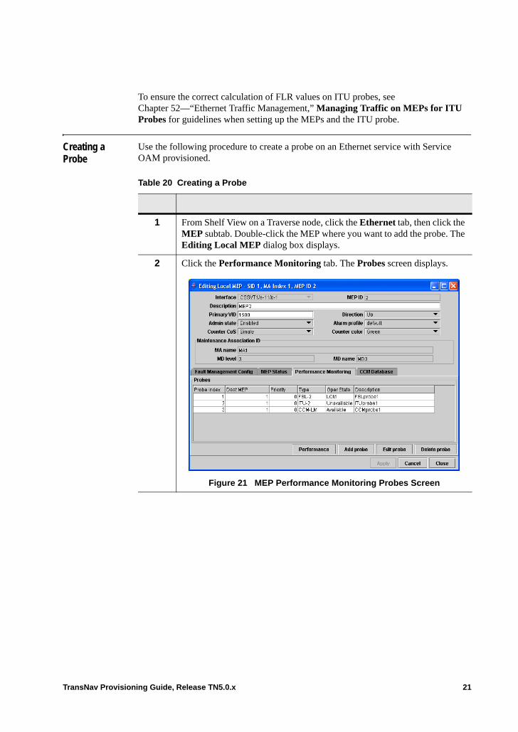
To ensure the correct calculation of FLR values on ITU probes, see Chapter 52—“Ethernet Traffic Management,” Managing Traffic on MEPs for ITU Probes for guidelines when setting up the MEPs and the ITU probe.
Creating a Probe
Use the following procedure to create a probe on an Ethernet service with Service OAM provisioned.
Table 20 Creating a Probe
1 From Shelf View on a Traverse node, click the Ethernet tab, then click the MEP subtab. Double-click the MEP where you want to add the probe. The Editing Local MEP dialog box displays.
2 Click the Performance Monitoring tab. The Probes screen displays.
Figure 21 MEP Performance Monitoring Probes Screen
TransNav Provisioning Guide, Release TN5.0.x 21
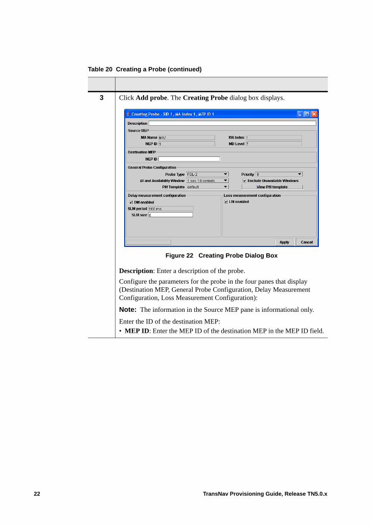
3 Click Add probe. The Creating Probe dialog box displays.
Figure 22 Creating Probe Dialog Box
Description: Enter a description of the probe.
Configure the parameters for the probe in the four panes that display (Destination MEP, General Probe Configuration, Delay Measurement Configuration, Loss Measurement Configuration):
Note: The information in the Source MEP pane is informational only.
Enter the ID of the destination MEP:• MEP ID: Enter the MEP ID of the destination MEP in the MEP ID field.
Table 20 Creating a Probe (continued)
22 TransNav Provisioning Guide, Release TN5.0.x
Define the following parameters in the General Probe Configuration pane. • Probe Type: Select the type of probe for this configuration. Valid values
are: FLS-2, ITU-2, or CCM-LM.
Note: The following two parameters, t and Availability Window are separate parameters but must be provisioned together; you cannot use one without the other. For CCM-LM probes, the t value must be much larger than the CCM rate, for example t = 1 second and CMM rate = 100 ms.
• t and Availability Window: Indicate the value to be used to report data. t is a short period over which measurements are aggregated to produce a short-period Frame Loss Ratio (FLR) number. Availability Window is the number of t periods that comprise an availability window. Valid values are:
– 1 sec 10 periods (default) (t = 1 second, availability window = 10 periods)
– 10 sec 6 periods (t = 10 seconds, availability window = 6 periods)
Note: The accuracy of the Loss Measurement results depends on the probe type, the t and Availability Window setting and the packet rate. For more information, see the Operations and Maintenance Guide, Chapter 7—“Ethernet Performance Parameters,” Ethernet Service OAM / Probe PM Template Tab Parameters.
• PM Template: Select the PM template to be used to control the collection of delay- and loss-measurement data with this probe.
• Priority: Indicate the priority to be associated with this probe. Valid values are 0 through 7. Default is 0.
• Exclude Unavailable Windows: Select the check box to indicate whether to exclude data collected during unavailable periods from PM records. Default is to exclude data. If selected, refresh values for events may appear to be invalid if data is refreshed before the availability window time frame has been reached. For example, if the selected Availability Window value is 1 second, 10 periods (10 seconds) data will be updated every 10 seconds. If users attempt to refresh the data every second, data will appear to be unchanging when, in fact, updates are in temporary storage pending the completion of the current Availability Window. For more information, see the Operations and Maintenance Guide, Chapter 11—“Loopback Tests,” Loopback and Link Trace on 10GbE and GbE-10 Ethernet Services.
Table 20 Creating a Probe (continued)
TransNav Provisioning Guide, Release TN5.0.x 23
4 Define the following parameters in the Delay measurement configuration and Loss measurement configuration panes. The parameters that display are different for each PM Probe type selected in the General Probe Configuration pane.
For the FLS-2 probe, configure the following parameters:• DM enabled: Select the check box to indicate if delay measurement
metrics should be measured. The system uses the same method to measure both delay and loss metrics for delay measurement. Valid values are: – Yes (default) – No (check box is not selected) If the check box is not selected, no statistics are calculated.
• SLM period: Indicates the period for SLM transmissions used to calculate delay and frame loss measurements between the MEPs in a probe. The Source MEP sends a synthetic loss message once every period. Valid values are: – 100 ms– 1 second (default)– 10 seconds
• SLM size: Indicates the bytes of data to include in the Data TLV. Valid values are 0 through 1460. Default is 0 (no Data TLV is included).
• LM enabled: Select the check box to indicate if loss measurement metrics should be measured. The system uses the same method to measure both delay and loss metrics for delay measurement. Valid values are: – Yes (default) – No (check box is not selected) If the check box is not selected, no statistics are calculated.
Table 20 Creating a Probe (continued)
24 TransNav Provisioning Guide, Release TN5.0.x
For the ITU-2 probe, configure the following parameters: • DM enabled: Select the check box to indicate if delay measurement
metrics should be measured. The system uses the same method to measure both delay and loss metrics for delay measurement. Valid values are Yes (default) and No (check box is not selected). If the check box is not selected, no statistics are calculated.
• DMM period: Indicates the period for DMM transmissions. This value is used to calculate delay and frame loss between the MEPs in a probe. Valid values are: – 100 ms– 1 second (default)– 10 seconds
• DMM data size: Indicates the bytes of data to include in the Data TLV. Valid values are 0 through 1460. Default is 0 (no Data TLV is included).
• LM enabled: Select the check box to indicate if loss measurement metrics should be measured. The system uses the same method to measure both delay and loss metrics for delay measurement. Valid values are:– Yes (default) – No (check box is not selected) If the check box is not selected, no statistics are calculated.
• LMM period: Indicates the Source MEP’s LM process sends loss measurement message (LMM) frames every 1 second.
For the CMM-LM probe, configure the following parameter:
LM enabled: Select the check box to indicate if loss measurement metrics should be measured. The system uses the same method to measure both delay and loss metrics for delay measurement. Valid values are:• Yes (default) • No (check box is not selected)
If the check box is not selected, no statistics are calculated.
5 Click Apply to accept the changes.
6 The Creating a Probe procedure is complete.
Table 20 Creating a Probe (continued)
TransNav Provisioning Guide, Release TN5.0.x 25
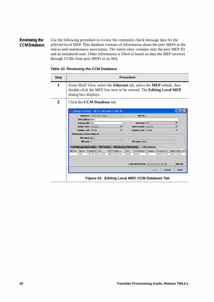
Reviewing the CCM Database
Use the following procedure to review the continuity check message data for the selected local MEP. This database consists of information about the peer MEPs in the end-to-end maintenance association. The initial entry contains only the peer MEP ID and an initialized state. Other information is filled in based on data the MEP receives through CCMs from peer MEPs in its MA.
Table 23 Reviewing the CCM Database
Step Procedure
1 From Shelf View, select the Ethernet tab, select the MEP subtab, then double-click the MEP line item to be viewed. The Editing Local MEP dialog box displays.
2 Click the CCM Database tab.
Figure 24 Editing Local MEP, CCM Database Tab
26 TransNav Provisioning Guide, Release TN5.0.x

3 Review the information from the following parameters that appear: • MEP ID: Indicates the user-assigned identifier of the peer MEP.• State: Indicates the operational state of the peer MEP. Valid values are:
Idle, Start, Failed, or OK. • FailedOK Time: The local clock time at which the operational became
Failed or OK.• MAC Address: Displays the MAC address of the peer MEP from its
continuity check message (CCM). If no CCM is received, the field is blank.
• RDI: Indicates the state of the remote defect indicator in the last received CCM. Valid values are True or False. If no CCMs are received, the value is False.
• Port Status: Indicates the latest port status received from the destination MEP. Valid values are: None, Blocked, or Up. If no CCMs are received, the value is None.
• IF Status: Indicates the latest interface status of the peer MEP. This status reflects the physical layer capability to send or receive frames. Valid values are: None, Up, Down, Testing, Unknown, Dormant, Not Present, or Lower Layer Down. If no CCMs are received, the value is None.
• Chassis ID: Identifies the Node ID received from the peer MEP. If no information is received in the latest CCM, the value is Blank.
• MgmtAddress: Indicates the management IP address received from the peer MEP. If no information is received in the latest CCM, the value is Blank.
• Last refresh time: Indicates the last date and time (in HH:MM:SS format) that the MEP status results were obtained.
4 Select Refresh to refresh the MEP CCM database results information.
5 Click Close to return to the Ethernet tab, MEP subtab screen.
6 The procedure Reviewing the CCM Database is complete.
Table 23 Reviewing the CCM Database (continued)
Step Procedure
TransNav Provisioning Guide, Release TN5.0.x 27

28 TransNav Provisioning Guide, Release TN5.0.x
Chapter 52 Ethernet Traffic Management
Introduction This chapter contains the following topics for Ethernet cards on the Traverse platform:• Ingress Traffic Flow• Egress Traffic Flow• Ethernet Traffic Management Description• Managing Traffic on EOP Ports• Managing Traffic on MEPs for ITU Probes• Maximum Information Rate• Broadcast Storm Control• Pause Control• Queuing Policy• Queuing Policy and Spanning Tree BPDUs• Marking Packets• Configure Marking
TransNav Provisioning Guide, Release TN5.0.x 1
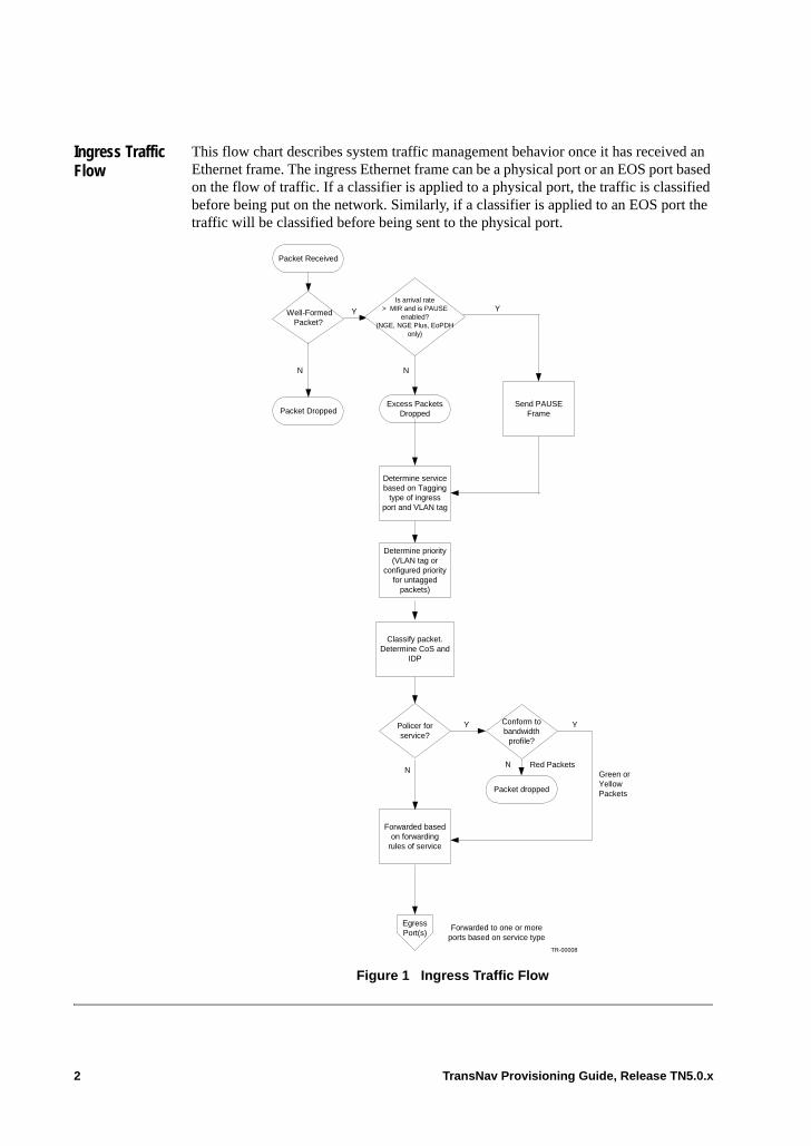
Ingress Traffic Flow
This flow chart describes system traffic management behavior once it has received an Ethernet frame. The ingress Ethernet frame can be a physical port or an EOS port based on the flow of traffic. If a classifier is applied to a physical port, the traffic is classified before being put on the network. Similarly, if a classifier is applied to an EOS port the traffic will be classified before being sent to the physical port.
Figure 1 Ingress Traffic Flow
N
Y
N Green orYellowPackets
TR-00008
Forwarded basedon forwarding
rules of service
Policer forservice?
Conform tobandwidth
profile?
Packet dropped
EgressPort(s)
Y
Red Packets
Forwarded to one or moreports based on service type
Determine priority(VLAN tag or
configured priorityfor untagged
packets)
Classify packet.Determine CoS and
IDP
Packet DroppedSend PAUSE
Frame
Packet Received
Well-FormedPacket?
Excess PacketsDropped
Y Y
N
Determine servicebased on Tagging
type of ingressport and VLAN tag
Is arrival rate> MIR and is PAUSE
enabled?(NGE, NGE Plus, EoPDH
only)
N
2 TransNav Provisioning Guide, Release TN5.0.x
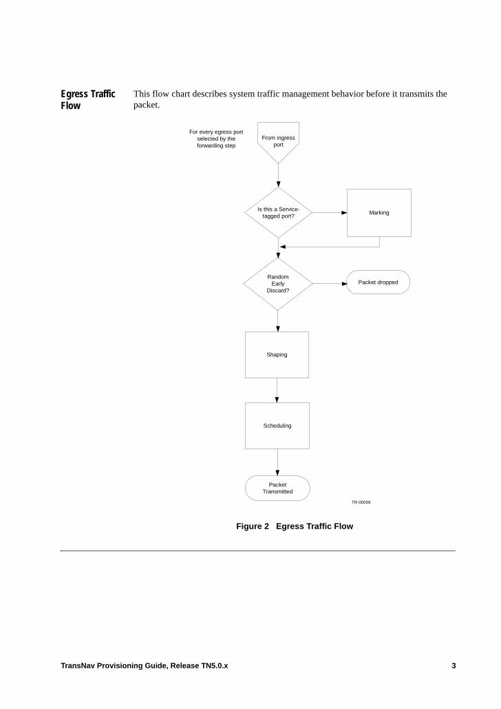
Egress Traffic Flow
This flow chart describes system traffic management behavior before it transmits the packet.
Figure 2 Egress Traffic Flow
From ingressport
Is this a Service-tagged port?
Marking
RandomEarly
Discard?
Packet dropped
Shaping
Scheduling
PacketTransmitted
For every egress portselected by theforwarding step
TR-00009
TransNav Provisioning Guide, Release TN5.0.x 3
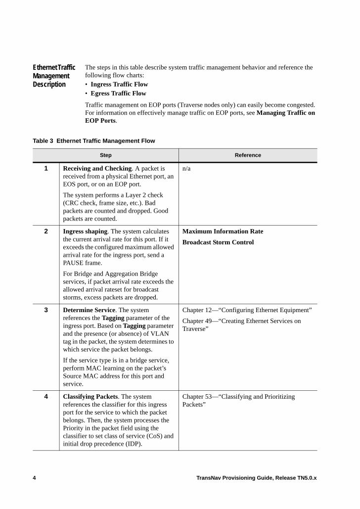
Ethernet Traffic Management Description
The steps in this table describe system traffic management behavior and reference the following flow charts:• Ingress Traffic Flow• Egress Traffic Flow
Traffic management on EOP ports (Traverse nodes only) can easily become congested. For information on effectively manage traffic on EOP ports, see Managing Traffic on EOP Ports.
Table 3 Ethernet Traffic Management Flow
Step Reference
1 Receiving and Checking. A packet is received from a physical Ethernet port, an EOS port, or on an EOP port.
The system performs a Layer 2 check (CRC check, frame size, etc.). Bad packets are counted and dropped. Good packets are counted.
n/a
2 Ingress shaping. The system calculates the current arrival rate for this port. If it exceeds the configured maximum allowed arrival rate for the ingress port, send a PAUSE frame.
For Bridge and Aggregation Bridge services, if packet arrival rate exceeds the allowed arrival rateset for broadcast storms, excess packets are dropped.
Maximum Information Rate
Broadcast Storm Control
3 Determine Service. The system references the Tagging parameter of the ingress port. Based on Tagging parameter and the presence (or absence) of VLAN tag in the packet, the system determines to which service the packet belongs.
If the service type is in a bridge service, perform MAC learning on the packet’s Source MAC address for this port and service.
Chapter 12—“Configuring Ethernet Equipment”
Chapter 49—“Creating Ethernet Services on Traverse”
4 Classifying Packets. The system references the classifier for this ingress port for the service to which the packet belongs. Then, the system processes the Priority in the packet field using the classifier to set class of service (CoS) and initial drop precedence (IDP).
Chapter 53—“Classifying and Prioritizing Packets”
4 TransNav Provisioning Guide, Release TN5.0.x
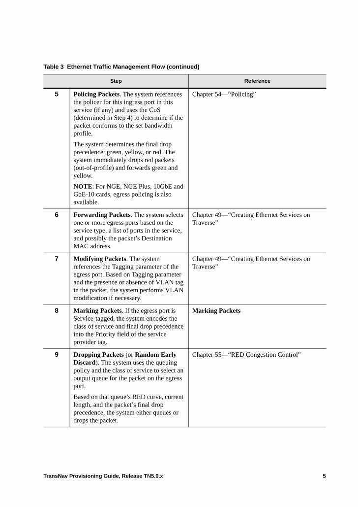
5 Policing Packets. The system references the policer for this ingress port in this service (if any) and uses the CoS (determined in Step 4) to determine if the packet conforms to the set bandwidth profile.
The system determines the final drop precedence: green, yellow, or red. The system immediately drops red packets (out-of-profile) and forwards green and yellow.
NOTE: For NGE, NGE Plus, 10GbE and GbE-10 cards, egress policing is also available.
Chapter 54—“Policing”
6 Forwarding Packets. The system selects one or more egress ports based on the service type, a list of ports in the service, and possibly the packet’s Destination MAC address.
Chapter 49—“Creating Ethernet Services on Traverse”
7 Modifying Packets. The system references the Tagging parameter of the egress port. Based on Tagging parameter and the presence or absence of VLAN tag in the packet, the system performs VLAN modification if necessary.
Chapter 49—“Creating Ethernet Services on Traverse”
8 Marking Packets. If the egress port is Service-tagged, the system encodes the class of service and final drop precedence into the Priority field of the service provider tag.
Marking Packets
9 Dropping Packets (or Random Early Discard). The system uses the queuing policy and the class of service to select an output queue for the packet on the egress port.
Based on that queue’s RED curve, current length, and the packet’s final drop precedence, the system either queues or drops the packet.
Chapter 55—“RED Congestion Control”
Table 3 Ethernet Traffic Management Flow (continued)
Step Reference
TransNav Provisioning Guide, Release TN5.0.x 5
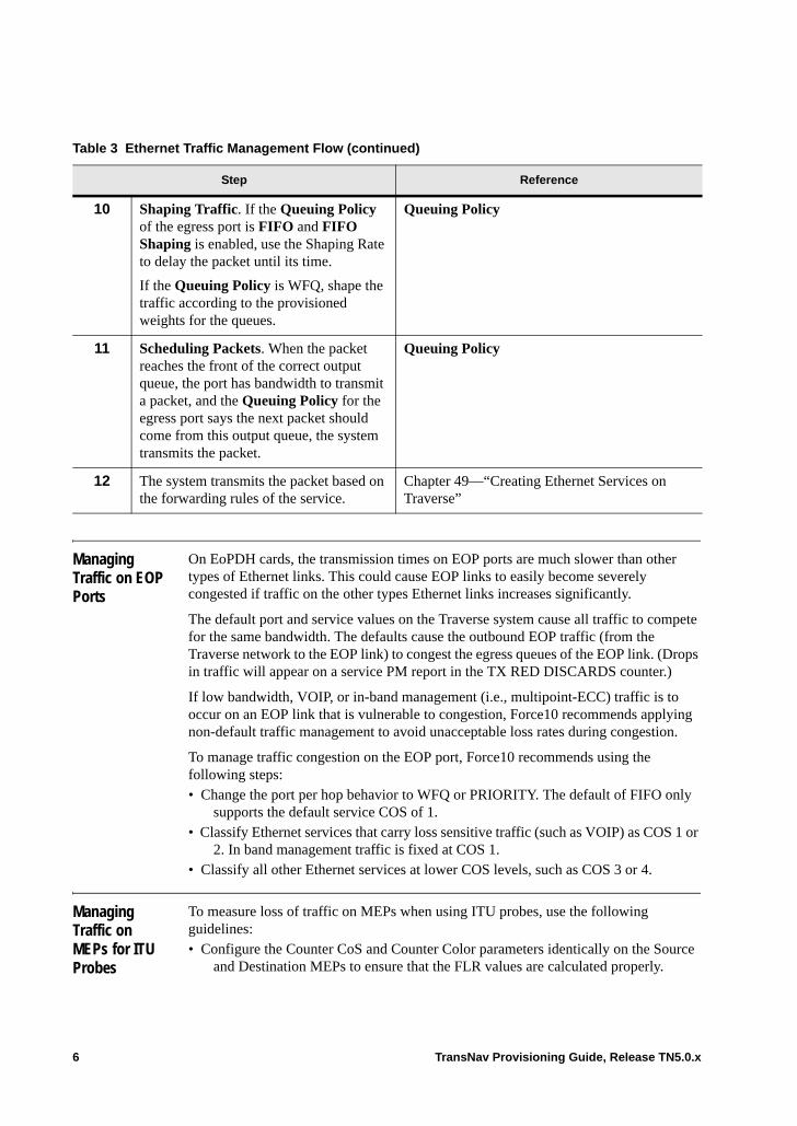
Managing Traffic on EOP Ports
On EoPDH cards, the transmission times on EOP ports are much slower than other types of Ethernet links. This could cause EOP links to easily become severely congested if traffic on the other types Ethernet links increases significantly.
The default port and service values on the Traverse system cause all traffic to compete for the same bandwidth. The defaults cause the outbound EOP traffic (from the Traverse network to the EOP link) to congest the egress queues of the EOP link. (Drops in traffic will appear on a service PM report in the TX RED DISCARDS counter.)
If low bandwidth, VOIP, or in-band management (i.e., multipoint-ECC) traffic is to occur on an EOP link that is vulnerable to congestion, Force10 recommends applying non-default traffic management to avoid unacceptable loss rates during congestion.
To manage traffic congestion on the EOP port, Force10 recommends using the following steps:• Change the port per hop behavior to WFQ or PRIORITY. The default of FIFO only
supports the default service COS of 1.• Classify Ethernet services that carry loss sensitive traffic (such as VOIP) as COS 1 or
2. In band management traffic is fixed at COS 1.• Classify all other Ethernet services at lower COS levels, such as COS 3 or 4.
Managing Traffic on MEPs for ITU Probes
To measure loss of traffic on MEPs when using ITU probes, use the following guidelines: • Configure the Counter CoS and Counter Color parameters identically on the Source
and Destination MEPs to ensure that the FLR values are calculated properly.
10 Shaping Traffic. If the Queuing Policy of the egress port is FIFO and FIFO Shaping is enabled, use the Shaping Rate to delay the packet until its time.
If the Queuing Policy is WFQ, shape the traffic according to the provisioned weights for the queues.
Queuing Policy
11 Scheduling Packets. When the packet reaches the front of the correct output queue, the port has bandwidth to transmit a packet, and the Queuing Policy for the egress port says the next packet should come from this output queue, the system transmits the packet.
Queuing Policy
12 The system transmits the packet based on the forwarding rules of the service.
Chapter 49—“Creating Ethernet Services on Traverse”
Table 3 Ethernet Traffic Management Flow (continued)
Step Reference
6 TransNav Provisioning Guide, Release TN5.0.x
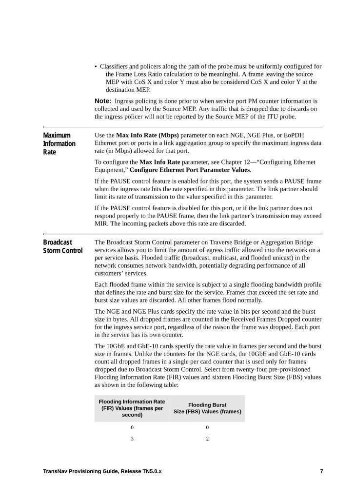
• Classifiers and policers along the path of the probe must be uniformly configured for the Frame Loss Ratio calculation to be meaningful. A frame leaving the source MEP with CoS X and color Y must also be considered CoS X and color Y at the destination MEP.
Note: Ingress policing is done prior to when service port PM counter information is collected and used by the Source MEP. Any traffic that is dropped due to discards on the ingress policer will not be reported by the Source MEP of the ITU probe.
Maximum Information Rate
Use the Max Info Rate (Mbps) parameter on each NGE, NGE Plus, or EoPDH Ethernet port or ports in a link aggregation group to specify the maximum ingress data rate (in Mbps) allowed for that port.
To configure the Max Info Rate parameter, see Chapter 12—“Configuring Ethernet Equipment,” Configure Ethernet Port Parameter Values.
If the PAUSE control feature is enabled for this port, the system sends a PAUSE frame when the ingress rate hits the rate specified in this parameter. The link partner should limit its rate of transmission to the value specified in this parameter.
If the PAUSE control feature is disabled for this port, or if the link partner does not respond properly to the PAUSE frame, then the link partner’s transmission may exceed MIR. The incoming packets above this rate are discarded.
Broadcast Storm Control
The Broadcast Storm Control parameter on Traverse Bridge or Aggregation Bridge services allows you to limit the amount of egress traffic allowed into the network on a per service basis. Flooded traffic (broadcast, multicast, and flooded unicast) in the network consumes network bandwidth, potentially degrading performance of all customers’ services.
Each flooded frame within the service is subject to a single flooding bandwidth profile that defines the rate and burst size for the service. Frames that exceed the set rate and burst size values are discarded. All other frames flood normally.
The NGE and NGE Plus cards specify the rate value in bits per second and the burst size in bytes. All dropped frames are counted in the Received Frames Dropped counter for the ingress service port, regardless of the reason the frame was dropped. Each port in the service has its own counter.
The 10GbE and GbE-10 cards specify the rate value in frames per second and the burst size in frames. Unlike the counters for the NGE cards, the 10GbE and GbE-10 cards count all dropped frames in a single per card counter that is used only for frames dropped due to Broadcast Storm Control. Select from twenty-four pre-provisioned Flooding Information Rate (FIR) values and sixteen Flooding Burst Size (FBS) values as shown in the following table:
Flooding Information Rate (FIR) Values (frames per
second)
Flooding Burst Size (FBS) Values (frames)
0 0
3 2
TransNav Provisioning Guide, Release TN5.0.x 7

Pause Control Auto-negotiation is a process described in IEEE 802.3 that allows two devices on an Ethernet segment (link partners) to determine mutually agreeable settings for speed, duplex, and flow control. The Traverse supports auto-negotiation for optical GBE, electrical GBE, and Fast Ethernet ports on NGE, NGE Plus, and EoPDH cards. By default, the auto-negotiation feature is always enabled.
The following sections detail how the system sends and receives PAUSE frames.
On Sending PAUSE frames. Whenever the Traverse receives a PAUSE frame from an Ethernet port, it responds by suspending its transmission of packets on that port for a short period. Transmitting a PAUSE frame transmission mechanism is a means for
6 4
12 8
24 16
48 32
95 64
191 128
381 256
763 512
1,526 1,024
3,052 2,048
6,103 4,096
12,206 8,192
24,412 16,384
48,824 32,768
97,649
195,297
390,595
781,189
1,562,378
3,124,756
6,249,513
12,499,026
Flooding Information Rate (FIR) Values (frames per
second)
Flooding Burst Size (FBS) Values (frames)
8 TransNav Provisioning Guide, Release TN5.0.x
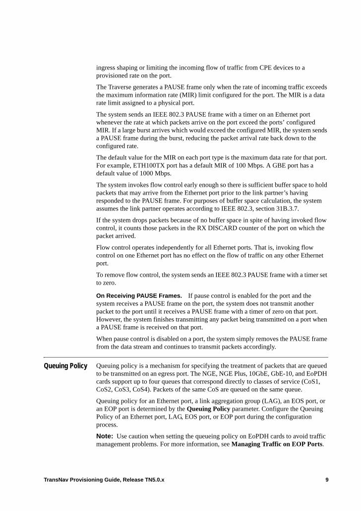
ingress shaping or limiting the incoming flow of traffic from CPE devices to a provisioned rate on the port.
The Traverse generates a PAUSE frame only when the rate of incoming traffic exceeds the maximum information rate (MIR) limit configured for the port. The MIR is a data rate limit assigned to a physical port.
The system sends an IEEE 802.3 PAUSE frame with a timer on an Ethernet port whenever the rate at which packets arrive on the port exceed the ports’ configured MIR. If a large burst arrives which would exceed the configured MIR, the system sends a PAUSE frame during the burst, reducing the packet arrival rate back down to the configured rate.
The default value for the MIR on each port type is the maximum data rate for that port. For example, ETH100TX port has a default MIR of 100 Mbps. A GBE port has a default value of 1000 Mbps.
The system invokes flow control early enough so there is sufficient buffer space to hold packets that may arrive from the Ethernet port prior to the link partner’s having responded to the PAUSE frame. For purposes of buffer space calculation, the system assumes the link partner operates according to IEEE 802.3, section 31B.3.7.
If the system drops packets because of no buffer space in spite of having invoked flow control, it counts those packets in the RX DISCARD counter of the port on which the packet arrived.
Flow control operates independently for all Ethernet ports. That is, invoking flow control on one Ethernet port has no effect on the flow of traffic on any other Ethernet port.
To remove flow control, the system sends an IEEE 802.3 PAUSE frame with a timer set to zero.
On Receiving PAUSE Frames. If pause control is enabled for the port and the system receives a PAUSE frame on the port, the system does not transmit another packet to the port until it receives a PAUSE frame with a timer of zero on that port. However, the system finishes transmitting any packet being transmitted on a port when a PAUSE frame is received on that port.
When pause control is disabled on a port, the system simply removes the PAUSE frame from the data stream and continues to transmit packets accordingly.
Queuing Policy Queuing policy is a mechanism for specifying the treatment of packets that are queued to be transmitted on an egress port. The NGE, NGE Plus, 10GbE, GbE-10, and EoPDH cards support up to four queues that correspond directly to classes of service (CoS1, CoS2, CoS3, CoS4). Packets of the same CoS are queued on the same queue.
Queuing policy for an Ethernet port, a link aggregation group (LAG), an EOS port, or an EOP port is determined by the Queuing Policy parameter. Configure the Queuing Policy of an Ethernet port, LAG, EOS port, or EOP port during the configuration process.
Note: Use caution when setting the queueing policy on EoPDH cards to avoid traffic management problems. For more information, see Managing Traffic on EOP Ports.
TransNav Provisioning Guide, Release TN5.0.x 9
• Chapter 12—“Configuring Ethernet Equipment,” Configure Ethernet Port Parameter Values
• Chapter 42—“Link Aggregation,” Create a Link Aggregation Group• Chapter 43—“Ethernet Over SONET/SDH (EOS),” Creating EOS Ports• Chapter 52—“Ethernet Traffic Management,” Managing Traffic on EOP Ports
In the Queuing Policy parameter, specify how the queues are managed. Use one of the following policies: • FIFO• Priority• Weighted Fair Queuing
FIFO First-in-first-out. Use this queuing policy to schedule all packets for transmission based on the FIFO algorithm. All traffic uses CoS1 or queue 1. Optionally, configure whether shaping should be employed using the following parameters.
Note: On EoPDH cards, Force10 recommends using WFQ or PRIORITY for the Queueing Policy to avoid traffic management problems under some conditions. For more information, see Managing Traffic on EOP Ports.
• FIFO Shape Enable. If the value in Queuing Policy is FIFO, specify if the system will use the number in the FIFO Shaping Rate parameter to shape the traffic being transmitted onto the port.
• FIFO Shaping Rate. If the FIFO Shaping Rate is enabled, specify a number between 1 and 1,000 Mbps TE-100 nodes and for NGE, NGE Plus, and EoPDH cards on Traverse nodes. For 10GbE and GbE-10 cards on Traverse nodes, specify a number between 1 and 10,000 Mbps; the default for the 10GbE is 10,000, the default for the GbE-10 is 1,000.
Priority Use this queuing policy to schedule all packets for transmission based on strict priority, using three priorities: high, medium, low. Highest priority traffic uses CoS1 (queue 1). Medium priority traffic uses CoS2 (queue 2). Low priority traffic uses CoS3 (queue 3).
Note: Force10 recommends using this queueing policy on EoPDH cards to avoid traffic management problems on EOP ports. For more information, see Managing Traffic on EOP Ports.
Higher priority queues always send queued packets. Only when all higher priority queues are empty does the scheduler look for a packet on a lower priority queue. Typical application is voice vs. data: voice requires low latency and should get absolute priority over data, i.e., whenever there is a voice packet, the system picks it over a data packet. Note that lower priorities can be starved (i.e., if voice traffic completely fills the output port, data traffic is never transmitted).
There are no additional parameters to configure to use with Priority queuing.
Weighted Fair Queuing
Use this queuing policy to guarantee a specific amount of the port’s bandwidth when there is congestion on the port. WFQ uses four classes of service (four queues) and the
10 TransNav Provisioning Guide, Release TN5.0.x

guarantees are specified as weights. If the value in Queuing Policy parameter is WFQ, specify the weights in the four WFQ CoS Weight {1 | 2 | 3 | 4} parameters.
Note: Force10 recommends using this queueing policy on EoPDH cards to avoid traffic management problems on EOP ports. For more information, see Managing Traffic on EOP Ports.
• WFQ CoS 1 Weight. Weighted queuing policy of CoS1. Enter a number between 1 and 100 to determine the proportion of bandwidth on this port for CoS1. The default value is 1 which means packets with the CoS1 have no priority in relation to the other classes of service.
• WFQ CoS 2 Weight. Weighted queuing policy of CoS2. Enter a number between 1 and 100 to determine the proportion of bandwidth on this port for CoS2. The default value is 1 which means packets with the CoS2 have no priority in relation to the other classes of service.
• WFQ CoS 3 Weight. Weighted queuing policy of CoS3. Enter a number between 1 and 100 to determine the proportion of bandwidth on this port for CoS3. The default value is 1 which means packets with the CoS3 have no priority in relation to the other classes of service.
• WFQ CoS 4 Weight. Weighted queuing policy of CoS4. Enter a number between 1 and 100 to determine the proportion of bandwidth on this port for CoS4. The default value is 1 which means packets with the CoS4 have no priority in relation to the other classes of service.
The scheduler uses these weights to allocate bandwidth on the port to each class of service. When there is no congestion, every CoS sends all queued packets. For example: weights 5, 25, 10, 1. (41 units). In times of congestion, CoS 1 traffic is guaranteed to get at least 12.2% (5/41) of bandwidth on the port. CoS 2 is guaranteed 62.5% (25/40). CoS 3 is guaranteed 25% (10/40). CoS 4 is guaranteed 2.5% (1/40).
Any bandwidth that is guaranteed for a queue but not actually needed by that queue is available for any other queue to use. For example, CoS 3, though guaranteed an allocation of 25%, is only transmitting enough data to use up 5%. That leaves 20% of the bandwidth of the port available for other queues to use. In this case, the scheduler distributes that unclaimed 20% approximately evenly among any queues that are already using up their entire guarantee. In particular, CoS 4, which has no guarantee, gets some of the unclaimed bandwidth from CoS 3.
Queuing Policy and Spanning Tree BPDUs
Spanning tree BPDUs (bridge protocol data units) prevent loops in network topologies used for Private LAN and Virtual Private LAN applications. When RSTP is enabled on an EOS port and there are activated bridge services using that EOS port, the system sends BPDUs on that port.
Therefore, BPDUs require being queued on the queues for that EOS port. The Queuing Policy parameter of the EOS port determines how they are queued.
If Queuing Policy is either FIFO or PQ. If the Queuing Policy for this EOS port is either FIFO or PQ, there is a separate, high-priority queue for BPDUs that is not used for customer packets. The scheduler sends spanning tree BPDUs on the port before service data. There is no contention between the BPDUs and the service data queued on that EOS port.
TransNav Provisioning Guide, Release TN5.0.x 11
If Queuing Policy is WFQ. If the Queuing Policy for this EOS is WFQ, then all service data sent to the EOS is queued on one of four service data queues. However, there is no separate system queue available for exclusive use of RSTP packets. The system uses CoS4 (queue 4).
Using CoS4 poses the following limitations:• BDPU packets may get queued behind lots of CoS 4 service packets, leading to
undesirably long delay.• If CoS 4 is assigned a Weight of 1, then packets of this CoS are transmitted only
when other CoSs with weights other than one are not using their weighted proportion of the available bandwidth. If other CoSs on this EOS port are using all of their weighted proportion, the scheduler for this EOS port will always select packets from those CoSs, leading to undesirably long delay for CoS 4 packets, including RSTP.
Therefore, if WFQ is the Queuing Policy and RSTP is enabled for this EOS port in an activated bridge service, use the following guidelines:• Ensure that the WFQ Weight CoS 4 parameter has a weight of more than one.
Force10 recommends setting weights on the EOS port such that the value in the WFQ Weight CoS4 parameter is at least 5% of the total.
• Ensure that the amount of CoS 4 service data queued for the EOS port is always small (or one). For example, use Classifiers on the service ports of the bridge service that do NOT classify packets into CoS4. Or, configure very small RED thresholds for the CoS 4 queues. (BPDUs are always queued without regard to RED thresholds, so setting small RED thresholds will not impede the transmission of BPDUs.)
Marking Packets
Marking is used to convey the results of a policing operation on a packet to other Ethernet cards that will process the same packet in the service provider’s network. Marking uses the 802.1p bits in the service provider VLAN tag. Specifically, the system uses the two most significant bits of the Priority field to encode the CoS and the least significant bit of the Priority field to encode the color.
Marking allows traffic to be classified and policed at the ingress node of a service provider’s network. Then, the results of those steps (CoS and color) are carried along as the packet goes through the service provider network. Marking allows traffic originally colored yellow at its ingress node to be the first candidate for dropping at subsequent aggregation points.
The system only marks packets if they transmit on a Service-tagged port. The system will always mark those packets in a way that reflects the results of the classification and policing steps. The system does not mark packets transmitting on a Port-based or Customer-tagged port.
12 TransNav Provisioning Guide, Release TN5.0.x
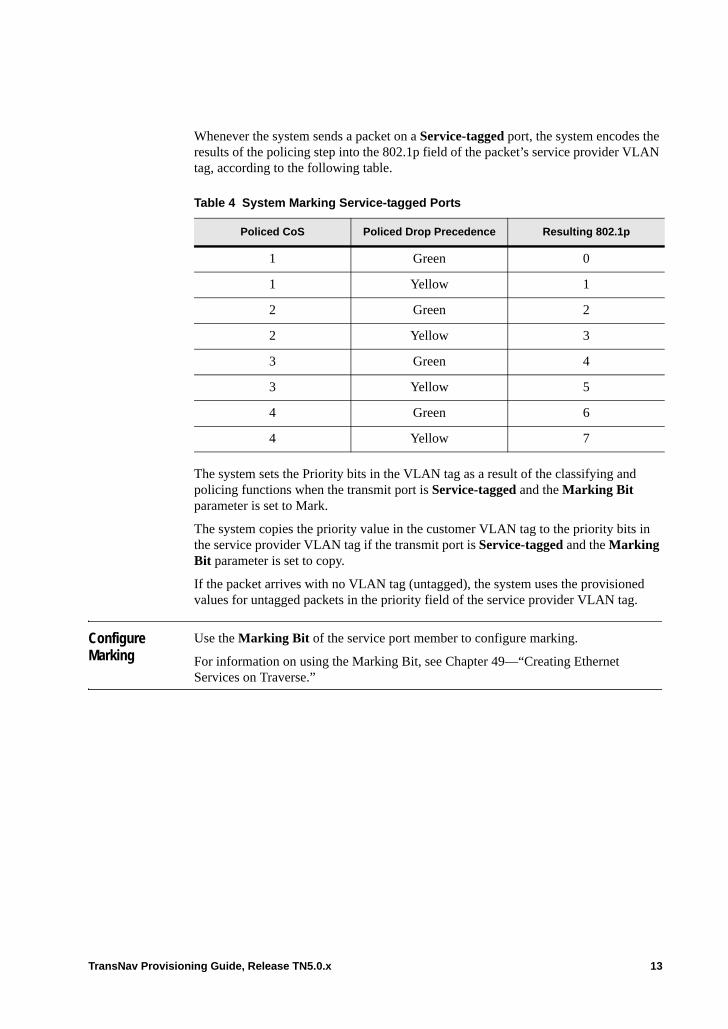
Whenever the system sends a packet on a Service-tagged port, the system encodes the results of the policing step into the 802.1p field of the packet’s service provider VLAN tag, according to the following table.
The system sets the Priority bits in the VLAN tag as a result of the classifying and policing functions when the transmit port is Service-tagged and the Marking Bit parameter is set to Mark.
The system copies the priority value in the customer VLAN tag to the priority bits in the service provider VLAN tag if the transmit port is Service-tagged and the Marking Bit parameter is set to copy.
If the packet arrives with no VLAN tag (untagged), the system uses the provisioned values for untagged packets in the priority field of the service provider VLAN tag.
Configure Marking
Use the Marking Bit of the service port member to configure marking.
For information on using the Marking Bit, see Chapter 49—“Creating Ethernet Services on Traverse.”
Table 4 System Marking Service-tagged Ports
Policed CoS Policed Drop Precedence Resulting 802.1p
1 Green 0
1 Yellow 1
2 Green 2
2 Yellow 3
3 Green 4
3 Yellow 5
4 Green 6
4 Yellow 7
TransNav Provisioning Guide, Release TN5.0.x 13

14 TransNav Provisioning Guide, Release TN5.0.x
Chapter 53 Classifying and Prioritizing Packets
Introduction The classification process establishes two things about a packet: its class of service (CoS) and its initial drop precedence (IDP).
This chapter contains the following topics:• Class of Service• Initial Drop Precedence• Default Classifier Template• Priority-based CoS• Port-Based CoS• Untagged Packets and Classification• Queuing Policy and Class of Service• Classifier Guidelines• Create Classifier Templates
Class of Service
Ethernet class of service refers to three bits within a four byte IEEE 802.1Q (VLAN) header used to indicate the priority of the Ethernet frame as it passes through a switched network. The priority bits in the IEEE 802.1Q header are referred to as the IEEE 802.1p bits. These three priority bits allow for eight classes (four classes with two colors -- green or yellow -- for each class).
The purpose of classifying traffic into different classes is to control how traffic is managed when there is congestion on an egress port. There is a relationship between the classification step, which takes place at ingress ports, and the RED and Queuing steps, which take place at egress ports. The service provider must carefully coordinate the configuration of the mechanisms that manage these steps and design and implement a coherent class of service policy for the network.
Upon arrival, the system looks at the 802.1p bits in the packet’s VLAN tag to assign both a class of service and an initial drop precedence to the packet. If the packet is untagged, it receives a default class of service and initial drop precedence.
On the Traverse system, there are four possible classes of service that map directly to four queues. See Chapter 52—“Ethernet Traffic Management,” Queuing Policy for the details on queuing and queuing policies.
TransNav Provisioning Guide, Release TN5.0.x 1

Initial Drop Precedence
It is possible that when a packet arrives at an ingress port, the customer equipment has already prioritized it to indicate some level of conformance within the customer’s own network. That is, the customer has encoded information about the packet’s conformance into the priority (802.1p) field. If the packet arrives on the port already with a priority, then the service provider should take that into consideration when the packet passes through the service provider’s bandwidth profile. That is, if the customer has already marked a packet yellow (high drop precedence), then even if the packet appears to conform to the service provider’s bandwidth profile, the packet should still be a candidate for dropping if there is congestion.
The term initial drop precedence (IDP) refers to this pre-prioritizing. The classification step reads the packet’s markings to set its IDP. The policing step (actually running the packet through the Traverse bandwidth profile) can modify that IDP to come up with a final drop precedence value.
Default Classifier Template
Defining a classifier template requires knowing the Queuing Policy of the egress port. See Chapter 52—“Ethernet Traffic Management,” Queuing Policy for information on queuing policies.
Create a classifier on the TransNav server using a combination of classes of service (queues) and the initial drop precedence (IDP) of the packet as it arrives on the port.
Priority-based CoS
You can configure Ethernet services on the Traverse system for a priority-based class of service. For example, a service purchased by Company A transports packets from several departments (Legal and Finance) within the company. The service provider and Company A agree that the Legal department’s traffic requires better service—more of the available bandwidth when there is congestion—than the Finance department’s traffic. The Legal and Finance departments would have different classes of service.
In another example, Company B might design a service where mixed voice and data traffic arrives on the same port. The voice traffic should be handled in one way (small throughput but with low latency and jitter), and the data traffic another (high
Table 1 Default Classifier Template
Priority Bits Class of Service IDP
Priority 0 1 Green
Priority 1 1 Green
Priority 2 1 Green
Priority 3 1 Green
Priority 4 1 Green
Priority 5 1 Green
Priority 6 1 Green
Priority 7 1 Green
2 TransNav Provisioning Guide, Release TN5.0.x
throughput but with higher acceptable latency and jitter). Voice and data would have different classes of services.
Both Company A and Company B would mark every packet’s traffic class by assigning a specific value to the Priority field (also called “802.1p bits”) in each Ethernet frame’s header. That is, Company A would use the Priority field to identify the department that generated the traffic. Company B would use the Priority field to identify the type of application (voice or data) that generated the traffic. In each case, the service provider would use a classifier to look at the priority value on each arriving packet and map that to a CoS.
Port-Based CoS
You can also configure Ethernet services using a port-based class of service. A service provider may have two customers – Company C and Company D – whose traffic arrives on different ports and is carried over the network on the same transport connection. Perhaps Company C pays more for its service, so Company C packets should get more of the shared transport capacity than packets belong to Company D. Each company would have different CoS defined for their traffic.
In this case, the service provider could use different classifiers on the two customers’ ports. The classifier on the Company C port assigns all packets to one CoS. The classifier on Company D port assigns all packets to a different CoS. This classifier would not interpret the Priority field of the packet at all.
Untagged Packets and Classification
Untagged packets do not have VLAN tags and therefore contain no 802.1p bits. However, these packets can still be assigned a CoS and IDP because they may end up competing for resources on a congested output port.
Use the Default Priority Bit parameter on an Ethernet service member to assign a priority to untagged Ethernet frames arriving on a member port. By default, the system assigns an 802.1p value for untagged packets of priority 1. See Chapter 49—“Creating Ethernet Services on Traverse,” Configure Ethernet Services to configure this parameter.
See the following topics for information on how the system processes untagged packets:• Chapter 50—“VLAN Tagging on Traverse Ethernet Services,” Mix of Port-based
and Service-tagged Ports in a Service• Chapter 50—“VLAN Tagging on Traverse Ethernet Services,” All Ports in a
Service are Customer-tagged• Chapter 50—“VLAN Tagging on Traverse Ethernet Services,” Mix of
Customer-tagged and Service-tagged Ports in a Service• Chapter 50—“VLAN Tagging on Traverse Ethernet Services,” All Ports in a
Service Are Tagged as Service-tagged
TransNav Provisioning Guide, Release TN5.0.x 3
Queuing Policy and Class of Service
Every egress port has a Queuing Policy that determines how many classes of services the port can differentiate and how those classes are treated with respect to each other. Depending on the egress port’s Queuing Policy, the Traverse supports different numbers of Classes of Service: • FIFO: one class• Priority Queuing: up to three classes• Weighted Fair Queuing: up to four classes
See Chapter 52—“Ethernet Traffic Management,” Queuing Policy for discussion about queuing policy.
Classifier Guidelines
Create a classifier on the TransNav server (classifier templates). The TransNav management system supports up to 12 classifier templates.
Each classifier template maps each possible 802.1p value (0 through 7) to a class of service and initial drop precedence pair. The default classifier template maps every 802.1p value to CoS=1, IDP=green. See Default Classifier Template.
Defining a classifier template requires knowing the Queuing Policy of the egress port. See Chapter 52—“Ethernet Traffic Management,” Queuing Policy for information on queuing policies.
It is possible to assign different classifier templates to different ports in the same service for NGE and EoPDH cards. On 10GbE and GbE-10 cards, assign the same classifier template to all service ports that share a port.
It is possible to change the assignment of classifier template to a port in a service, while that service is activated. The new template takes effect with no interruption to the service.
It is possible to edit a classifier template to change the mapping of 802.1p values to (CoS, IDP), and to synchronize the edited template. The new values takes effect with no interruption to any activated services that use the template.
You cannot delete a classifier template if there are any provisioned or activated Ethernet services that currently use or are provisioned with that classifier template.
4 TransNav Provisioning Guide, Release TN5.0.x
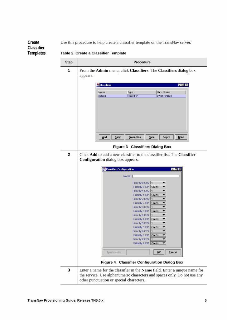
Create Classifier Templates
Use this procedure to help create a classifier template on the TransNav server.
Table 2 Create a Classifier Template
Step Procedure
1 From the Admin menu, click Classifiers. The Classifiers dialog box appears.
Figure 3 Classifiers Dialog Box
2 Click Add to add a new classifier to the classifier list. The Classifier Configuration dialog box appears.
Figure 4 Classifier Configuration Dialog Box
3 Enter a name for the classifier in the Name field. Enter a unique name for the service. Use alphanumeric characters and spaces only. Do not use any other punctuation or special characters.
TransNav Provisioning Guide, Release TN5.0.x 5
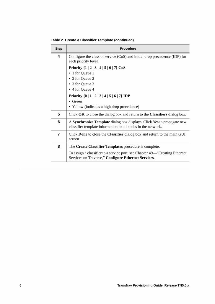
4 Configure the class of service (CoS) and initial drop precedence (IDP) for each priority level.
Priority {1 | 2 | 3 | 4 | 5 | 6 | 7} CoS• 1 for Queue 1• 2 for Queue 2• 3 for Queue 3• 4 for Queue 4
Priority {0 | 1 | 2 | 3 | 4 | 5 | 6 | 7} IDP• Green• Yellow (indicates a high drop precedence)
5 Click OK to close the dialog box and return to the Classifiers dialog box.
6 A Synchronize Template dialog box displays. Click Yes to propagate new classifier template information to all nodes in the network.
7 Click Done to close the Classifier dialog box and return to the main GUI screen.
8 The Create Classifier Templates procedure is complete.
To assign a classifier to a service port, see Chapter 49—“Creating Ethernet Services on Traverse,” Configure Ethernet Services.
Table 2 Create a Classifier Template (continued)
Step Procedure
6 TransNav Provisioning Guide, Release TN5.0.x
Chapter 54 Policing
Introduction This chapter contains the following topics:• Policing Packets• Bandwidth Profiles• Example Bandwidth Profiles• Create a Bandwidth Profile• Policers• Policing Algorithm• Guidelines to Create a Policer• Create Traffic Policers on the Ethernet Card
Policing Packets
Policing is the process of measuring a stream of traffic against a bandwidth profile to determine conformance of each packet with that profile. By the time a packet is presented to the Policer, it has already been assigned an initial drop precedence value as described in Chapter 53—“Classifying and Prioritizing Packets.” The result of policing will be to assign to each packet a final drop precedence value. This value represents the conformance of the packet to the profile.
Drop precedence, or conformance, is used in the random early discard (RED) queuing step. When there is congestion on an output port (packets are forwarded to a port at a rate that exceeds the transmission rate of the port), then packets start to back up on the queues for that port. RED decides whether each individual packet should be queued or dropped, depending on the drop precedence value. Packets that do not conform to CIR but conform to PIR (yellow, or high, drop precedence) should be dropped before the packets that conform to CIR (green, or low, drop precedence).
Policing uses a variant of an algorithm called “two rate three color marker” and is implemented through two mechanisms: policers and bandwidth profiles. • Bandwidth Profiles. A bandwidth profile is a set of values that define the rate and
size of a pair of token buckets. • Policers. A policer is a pair of token buckets.
A bandwidth profile is a sort of template for making a pair of buckets. A policer as the actual bucket pair that results from following the instructions. The distinction is important, since the two types of objects are constructed and used in very different ways.
TransNav Provisioning Guide, Release TN5.0.x 1
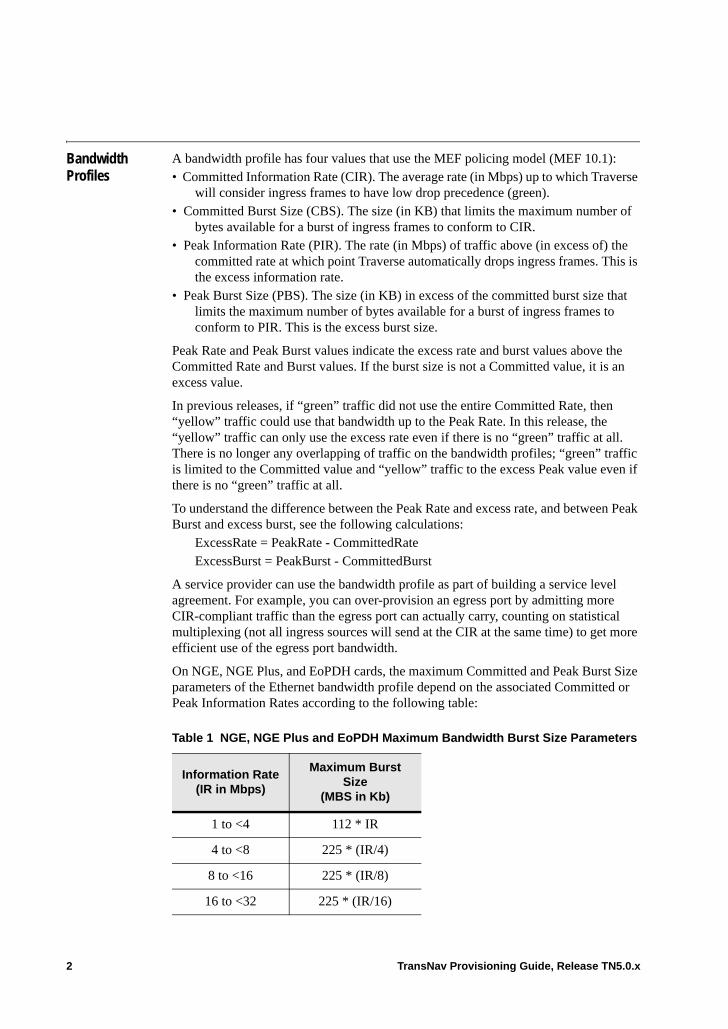
Bandwidth Profiles
A bandwidth profile has four values that use the MEF policing model (MEF 10.1):• Committed Information Rate (CIR). The average rate (in Mbps) up to which Traverse
will consider ingress frames to have low drop precedence (green). • Committed Burst Size (CBS). The size (in KB) that limits the maximum number of
bytes available for a burst of ingress frames to conform to CIR.• Peak Information Rate (PIR). The rate (in Mbps) of traffic above (in excess of) the
committed rate at which point Traverse automatically drops ingress frames. This is the excess information rate.
• Peak Burst Size (PBS). The size (in KB) in excess of the committed burst size that limits the maximum number of bytes available for a burst of ingress frames to conform to PIR. This is the excess burst size.
Peak Rate and Peak Burst values indicate the excess rate and burst values above the Committed Rate and Burst values. If the burst size is not a Committed value, it is an excess value.
In previous releases, if “green” traffic did not use the entire Committed Rate, then “yellow” traffic could use that bandwidth up to the Peak Rate. In this release, the “yellow” traffic can only use the excess rate even if there is no “green” traffic at all. There is no longer any overlapping of traffic on the bandwidth profiles; “green” traffic is limited to the Committed value and “yellow” traffic to the excess Peak value even if there is no “green” traffic at all.
To understand the difference between the Peak Rate and excess rate, and between Peak Burst and excess burst, see the following calculations:
ExcessRate = PeakRate - CommittedRateExcessBurst = PeakBurst - CommittedBurst
A service provider can use the bandwidth profile as part of building a service level agreement. For example, you can over-provision an egress port by admitting more CIR-compliant traffic than the egress port can actually carry, counting on statistical multiplexing (not all ingress sources will send at the CIR at the same time) to get more efficient use of the egress port bandwidth.
On NGE, NGE Plus, and EoPDH cards, the maximum Committed and Peak Burst Size parameters of the Ethernet bandwidth profile depend on the associated Committed or Peak Information Rates according to the following table:
Table 1 NGE, NGE Plus and EoPDH Maximum Bandwidth Burst Size Parameters
Information Rate(IR in Mbps)
Maximum Burst Size
(MBS in Kb)
1 to <4 112 * IR
4 to <8 225 * (IR/4)
8 to <16 225 * (IR/8)
16 to <32 225 * (IR/16)
2 TransNav Provisioning Guide, Release TN5.0.x

On NGE, NGE Plus, and EoPDH cards, if you provision a burst size (committed or peak) that is less than or equal to the calculated maximum burst size for your given information rate, the system uses the provisioned burst size. However, if you provision a burst size that is larger than the calculated maximum burst size for the given information rate, the system uses the calculated maximum burst size. Examples are as follows:• If a CIR of 50 and a CBS of 256 is provisioned, the calculated maximum CBS for a
CIR of 50 is 351. The provisioned value is less than 351, so the system implements the provisioned value of 256.
• If a PIR of 100 and a PBS of 768 are provisioned, the excess burst size is 512 (this is PBS minus the CBS). This value is greater than the calculated maximum burst size for this PIR, so the system ignores the provisioned value and implements the calculated value of 351.
Example Bandwidth Profiles
Each bandwidth profile can be used many times to create many different policers. Typically, a service provider will define a set of service offerings, create a bandwidth profile for each, and then sell those service offerings to many customers. The following table contains a set of service offerings. Only the rates are shown (burst sizes will be provisioned too):
32 to <64 225 * (IR/32)
64 to <128 225 * (IR/64)
IR > 128 225 * (IR/128)
Table 1 NGE, NGE Plus and EoPDH Maximum Bandwidth Burst Size Parameters
Information Rate(IR in Mbps)
Maximum Burst Size
(MBS in Kb)
Table 2 Sample Bandwidth Profiles
Package Name CIR PIR
Gold 100 100 Mbps 100 Mbps
Gold 200 200 Mbps 200 Mbps
Gold 300 300 Mbps 300 Mbps
Silver 50 50 Mbps 500 Mbps
Silver 150 150 Mbps 500 Mbps
Silver 250 250 Mbps 1000 Mbps
Best Effort Small 0 Mbps 50 Mbps
Best Effort Large 0 Mbps 1000 Mbps
TransNav Provisioning Guide, Release TN5.0.x 3
The Gold packages have the same value for CIR and PIR. Everything up to CIR is colored green. Because CIR and PIR are the same, any policers using this bandwidth profile do not color anything yellow. All traffic with an initial drop precedence of yellow is dropped. Green packets are more likely to be queued for the egress port than yellow packets that may be submitted by a service running a different bandwidth profile. In a Gold package, any arriving traffic that exceeds the CIR is unconditionally dropped, whether or not there is available bandwidth on the egress port.
The Silver packages have smaller committed rates, but larger excess rates. Silver traffic that conforms to the CIR (green) is treated just like traffic from the Gold packages. Silver traffic that conforms to PIR (yellow) is accepted, but may be dropped if the queue is backed up. If the egress port is free or only slightly backed up at the moment, the yellow traffic will be queued along with the green. When the egress port is lightly loaded, a “Silver 50” customer can get up to 500 Mbps. As the egress port’s use increases, yellow traffic is increasingly dropped instead of queued. When the egress port is saturated, all of the yellow traffic will be dropped and the “Silver 50” customer will be getting only 50 Mbps.
The Best Effort packages have no committed rate. In Best Effort Small, up to 50 Mbps of the customer’s traffic is colored yellow and anything over 50 Mbps is dropped. Yellow traffic gets through only if there is available bandwidth. If there is enough green traffic to fill up the egress port, all of the yellow traffic will get dropped. Best Effort Large is similar except that 1,000 Mbps of the customer’s traffic – up to full line rate on a GbE port – is conditionally accepted (yellow). Sometimes all of this customer’s traffic will get through; sometimes all of it will be dropped.
4 TransNav Provisioning Guide, Release TN5.0.x
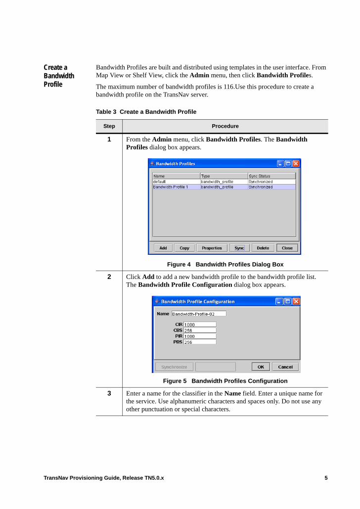
Create a Bandwidth Profile
Bandwidth Profiles are built and distributed using templates in the user interface. From Map View or Shelf View, click the Admin menu, then click Bandwidth Profiles.
The maximum number of bandwidth profiles is 116.Use this procedure to create a bandwidth profile on the TransNav server.
Table 3 Create a Bandwidth Profile
Step Procedure
1 From the Admin menu, click Bandwidth Profiles. The Bandwidth Profiles dialog box appears.
Figure 4 Bandwidth Profiles Dialog Box
2 Click Add to add a new bandwidth profile to the bandwidth profile list. The Bandwidth Profile Configuration dialog box appears.
Figure 5 Bandwidth Profiles Configuration
3 Enter a name for the classifier in the Name field. Enter a unique name for the service. Use alphanumeric characters and spaces only. Do not use any other punctuation or special characters.
TransNav Provisioning Guide, Release TN5.0.x 5
Policers Policing is the act of measuring a flow of packets, coloring packets green or yellow (or dropping them) in accordance with a bandwidth profile. Bandwidth profiles must be created before policers can be created on the node.
Policing is optional. By default, when you add a port to a service, the flow of packets on that service port is not policed. That means that the color that was set for a packet by the service port’s classifier (by default, this is green) is preserved.
Traverse performs policing by class of service. When packets arrive at a policer, each one has already been assigned a class of service. Each packet is policed according to the bandwidth profile for its class of service.
Note that this means that it is not possible to classify traffic into two classes—one for voice and one for data—and then police the aggregate of the two classes. To queue voice and data separately, which will be a common application, police them separately.
You can assign a single policer to multiple service ports. All flows on those service ports will be policed together and will compete for the bandwidth being policed.
4 Enter the following rates and burst sizes:• CIR. Committed information rate. For NGE and EoPDH cards, enter a
value between 0 and 1000 Mbps; for 10GbE and GbE-10 cards, enter a value between 0 and 10,000 Mpbs. Provisionable in increments of 1 Mbps.
• CBS. Committed burst size. For NGE and EoPDH cards, enter a value between 0 and 1,000 KB. For 10GbE and GbE-10 cards, enter a value between 0 and 16,000 KB. Provisionable in increments of 1 KB.
• PIR. Peak information rate. Enter a value between 1 and 10,000 Mbps. Provisionable in increments of 1 Mbps. The PIR value cannot be less than the CIR value.
• PBS. Peak burst size. Enter a value between 2 and 16,000 KB. Provisionable in increments of 1 KB.
5 A Synchronize Template dialog box displays. Click Yes to propagate new bandwidth profile template information to all nodes in the network.
6 Click Done to close the Classifier dialog box and return to the main screen.
7 Repeat Steps 1 to 6 for as many bandwidth profiles are required in the network.
8 The Create a Bandwidth Profile procedure is complete.
Table 3 Create a Bandwidth Profile (continued)
Step Procedure
6 TransNav Provisioning Guide, Release TN5.0.x
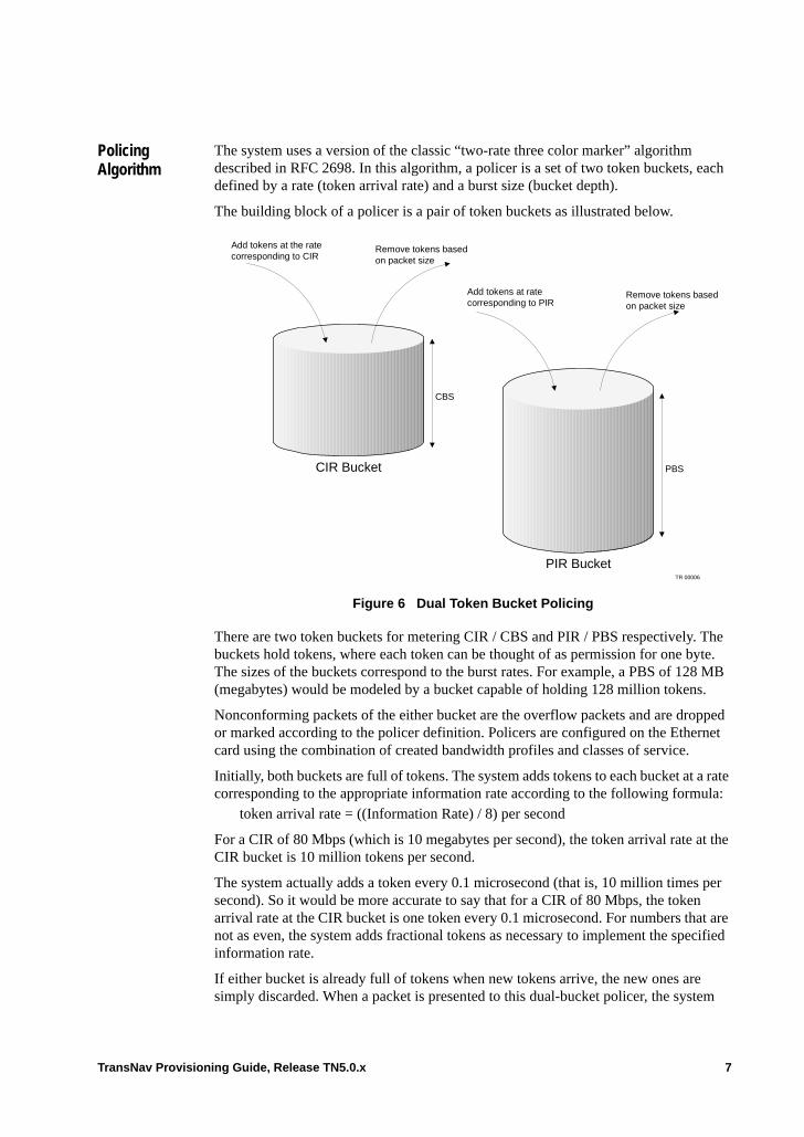
Policing Algorithm
The system uses a version of the classic “two-rate three color marker” algorithm described in RFC 2698. In this algorithm, a policer is a set of two token buckets, each defined by a rate (token arrival rate) and a burst size (bucket depth).
The building block of a policer is a pair of token buckets as illustrated below.
Figure 6 Dual Token Bucket Policing
There are two token buckets for metering CIR / CBS and PIR / PBS respectively. The buckets hold tokens, where each token can be thought of as permission for one byte. The sizes of the buckets correspond to the burst rates. For example, a PBS of 128 MB (megabytes) would be modeled by a bucket capable of holding 128 million tokens.
Nonconforming packets of the either bucket are the overflow packets and are dropped or marked according to the policer definition. Policers are configured on the Ethernet card using the combination of created bandwidth profiles and classes of service.
Initially, both buckets are full of tokens. The system adds tokens to each bucket at a rate corresponding to the appropriate information rate according to the following formula:
token arrival rate = ((Information Rate) / 8) per second
For a CIR of 80 Mbps (which is 10 megabytes per second), the token arrival rate at the CIR bucket is 10 million tokens per second.
The system actually adds a token every 0.1 microsecond (that is, 10 million times per second). So it would be more accurate to say that for a CIR of 80 Mbps, the token arrival rate at the CIR bucket is one token every 0.1 microsecond. For numbers that are not as even, the system adds fractional tokens as necessary to implement the specified information rate.
If either bucket is already full of tokens when new tokens arrive, the new ones are simply discarded. When a packet is presented to this dual-bucket policer, the system
CIR Bucket
PIR Bucket
CBS
PBS
Add tokens at the ratecorresponding to CIR
Remove tokens basedon packet size
Add tokens at ratecorresponding to PIR
Remove tokens basedon packet size
TR 00006
TransNav Provisioning Guide, Release TN5.0.x 7
assigns a final drop precedence to the packet for traffic management at subsequent nodes in the provider network. The final drop precedence will be one of the following colors: • Green: classifier-assigned green and in CIR/CBS profile for corresponding CoS.• Yellow: classifier-assigned green and out of CIR/CBS profile but within PIR/PBS
profile, or classifier-assigned yellow and in PIR/BPS profile for corresponding CoS.
• Red: green or yellow and out of profile.
At the conclusion of the policing step, every packet has a final drop precedence of red, yellow, or green, recording its conformance to the bandwidth profile for its CoS. Red packets are automatically dropped. Yellow and green packets proceed to the queuing step.
Bandwidth Profiles and Policers
Bandwidth profiles and policers are related features. A bandwidth profile is like a recipe for making a pair of token buckets and is configured using templates in the TransNav management server. The TransNav management system supports a small number of network-wide recipes.
A policer is an actual set of token bucket pairs, one pair per CoS per port (Ethernet, EOS, or EOP). Policers are configured on an Ethernet card. Many policers can use the same recipe but still operate completely independently. Traffic flowing through Policer A can never affect the coloring of traffic flowing through Policer B, even if both policers use the same bandwidth profiles.
Guidelines to Create a Policer
There are no policers on a card until the service provider creates them. Policers can be selected by policer ID or by the corresponding User tag for that policer ID.
Each Ethernet card supports up to 1,024 policers. However, it will be more common to have just a few.
Important: Multiple services using the same policer on an ingress port share the total policer bandwidth. If you need the total policer bandwidth for each service, then create and assign a separate policer per service.
In addition to policing on ingress ports, egress policing is also available on Bridge and Aggregation Bridge services on NGE, NGE Plus, 10GbE and GbE-10 cards. Useful in applications where multiple services share the same egress link, the egress link can be a customer-facing port (UNI) or a network-facing “trunk” port (NNI). These Bridge services can support either ingress policing or egress policing, but not both types of policing simultaneously. The policing type can be changed when the service is inactive or when no policers are assigned to an active service’s service ports.
8 TransNav Provisioning Guide, Release TN5.0.x

A policer has a separate bandwidth profile template for every class of service. When you create a policer, its default configuration is to use the bandwidth profile named “default” for every class. The default configuration for a newly-created policer is described in the following table.
Create Traffic Policers on the Ethernet Card
Use the following procedure to create a policer on an Ethernet card.
Table 7 Default Policer
Class of Service Bandwidth Profile
1 Default
2 Default
3 Default
4 Default
Table 8 Create Traffic Policers on the Ethernet Card
Step Procedure
1 Complete the Create a Bandwidth Profile procedure for as many bandwidth profiles as are required in the network.
2 In Shelf View, click the Ethernet tab, then click the Policer subtab.
Figure 9 Ethernet Tab, Policer Subtab
TransNav Provisioning Guide, Release TN5.0.x 9
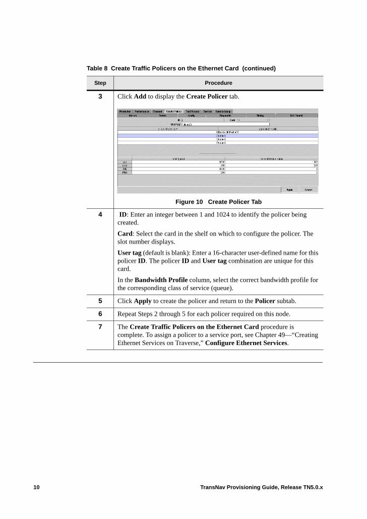
3 Click Add to display the Create Policer tab.
Figure 10 Create Policer Tab
4 ID: Enter an integer between 1 and 1024 to identify the policer being created.
Card: Select the card in the shelf on which to configure the policer. The slot number displays.
User tag (default is blank): Enter a 16-character user-defined name for this policer ID. The policer ID and User tag combination are unique for this card.
In the Bandwidth Profile column, select the correct bandwidth profile for the corresponding class of service (queue).
5 Click Apply to create the policer and return to the Policer subtab.
6 Repeat Steps 2 through 5 for each policer required on this node.
7 The Create Traffic Policers on the Ethernet Card procedure is complete. To assign a policer to a service port, see Chapter 49—“Creating Ethernet Services on Traverse,” Configure Ethernet Services.
Table 8 Create Traffic Policers on the Ethernet Card (continued)
Step Procedure
10 TransNav Provisioning Guide, Release TN5.0.x
Chapter 55 RED Congestion Control
Introduction This chapter contains the following topics:• Random Early Discard• System Defaults for RED Thresholds• Customize RED Thresholds• View Current System RED Thresholds
Random Early Discard
Random early discard (RED) manages congestion on the egress port on all Ethernet cards except the GbE-10 and 10GbE. Packets are queued because the egress port is already transmitting a packet. RED manages two queuing issues: • Buffer usage. Instead of letting queued packets pile up indefinitely, potentially using
up all the buffers, there is limit on queue buffer consumption. This means some packets sent to the queue have to get dropped.
• Latency. The longer the queue gets, the more packets are delayed before they finally are transmitted. Different applications have different amount of delay tolerance. For example, better to drop voice packets than hold them back for a long time. So, RED drops packets.
The simplest form of dropping packets from the end of a full queue. A queue has a fixed length. The queue is considered full when the queue reaches that length. All packets that arrive after the queue is full are dropped.
The Traverse system uses a probabilistic drop mechanism instead of a fixed length queue. At a given queue length, some packets are dropped and others are queued. Below some length all packets are queued, then there is a range within which packets are dropped with probability that increases linearly from 0 to 100. Then, all packets are dropped. The specification of these lengths is called a RED curve.
Traverse RED Curves
The RED curve on the Traverse system for all Ethernet cards except GbE-10 and 10GbE is weighted by packet color: one RED curve for green packets and another for yellow packets. The system starts dropping yellow packets before the green packets. When a port reaches a certain length, the system randomly drops some yellow packets and queues other yellow packets, while still queuing all green. As the length of the queue increases, the system drops a higher percentage of yellow packets, but still accepts all green packets.
TransNav Provisioning Guide, Release TN5.0.x 1
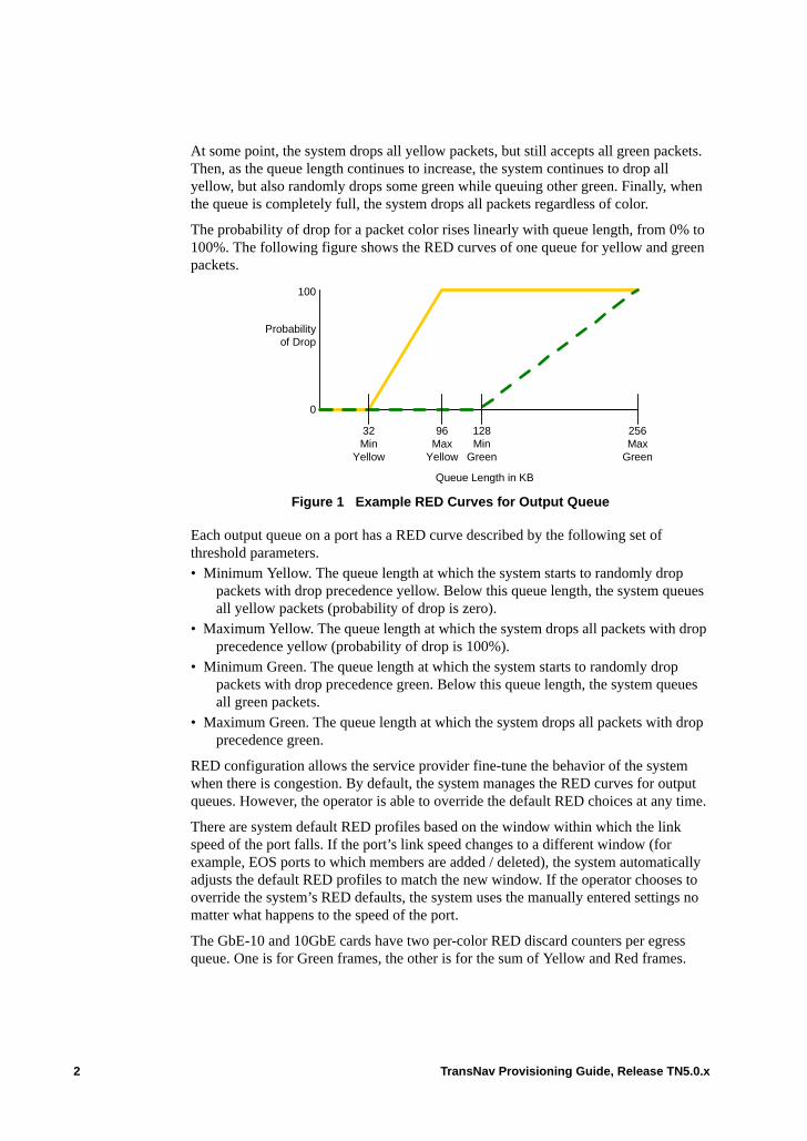
At some point, the system drops all yellow packets, but still accepts all green packets. Then, as the queue length continues to increase, the system continues to drop all yellow, but also randomly drops some green while queuing other green. Finally, when the queue is completely full, the system drops all packets regardless of color.
The probability of drop for a packet color rises linearly with queue length, from 0% to 100%. The following figure shows the RED curves of one queue for yellow and green packets.
Figure 1 Example RED Curves for Output Queue
Each output queue on a port has a RED curve described by the following set of threshold parameters.• Minimum Yellow. The queue length at which the system starts to randomly drop
packets with drop precedence yellow. Below this queue length, the system queues all yellow packets (probability of drop is zero).
• Maximum Yellow. The queue length at which the system drops all packets with drop precedence yellow (probability of drop is 100%).
• Minimum Green. The queue length at which the system starts to randomly drop packets with drop precedence green. Below this queue length, the system queues all green packets.
• Maximum Green. The queue length at which the system drops all packets with drop precedence green.
RED configuration allows the service provider fine-tune the behavior of the system when there is congestion. By default, the system manages the RED curves for output queues. However, the operator is able to override the default RED choices at any time.
There are system default RED profiles based on the window within which the link speed of the port falls. If the port’s link speed changes to a different window (for example, EOS ports to which members are added / deleted), the system automatically adjusts the default RED profiles to match the new window. If the operator chooses to override the system’s RED defaults, the system uses the manually entered settings no matter what happens to the speed of the port.
The GbE-10 and 10GbE cards have two per-color RED discard counters per egress queue. One is for Green frames, the other is for the sum of Yellow and Red frames.
Probabilityof Drop
32Min
Yellow
96Max
Yellow
128Min
Green
256Max
Green
0
100
Queue Length in KB
2 TransNav Provisioning Guide, Release TN5.0.x
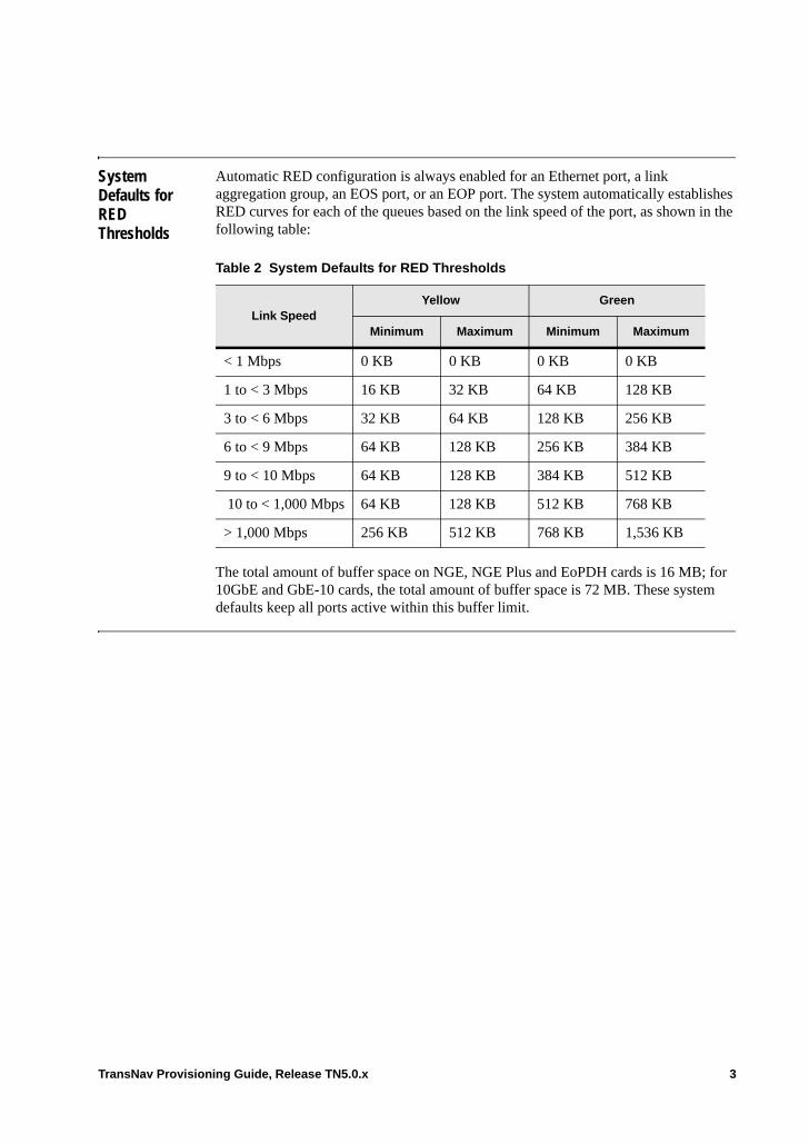
System Defaults for RED Thresholds
Automatic RED configuration is always enabled for an Ethernet port, a link aggregation group, an EOS port, or an EOP port. The system automatically establishes RED curves for each of the queues based on the link speed of the port, as shown in the following table:
The total amount of buffer space on NGE, NGE Plus and EoPDH cards is 16 MB; for 10GbE and GbE-10 cards, the total amount of buffer space is 72 MB. These system defaults keep all ports active within this buffer limit.
Table 2 System Defaults for RED Thresholds
Link SpeedYellow Green
Minimum Maximum Minimum Maximum
< 1 Mbps 0 KB 0 KB 0 KB 0 KB
1 to < 3 Mbps 16 KB 32 KB 64 KB 128 KB
3 to < 6 Mbps 32 KB 64 KB 128 KB 256 KB
6 to < 9 Mbps 64 KB 128 KB 256 KB 384 KB
9 to < 10 Mbps 64 KB 128 KB 384 KB 512 KB
10 to < 1,000 Mbps 64 KB 128 KB 512 KB 768 KB
> 1,000 Mbps 256 KB 512 KB 768 KB 1,536 KB
TransNav Provisioning Guide, Release TN5.0.x 3

Customize RED Thresholds
Use the following procedure to help you customize RED thresholds for an Ethernet, EOS, or EOP port.
Table 3 Customize RED Thresholds for a Port
Step Procedure
1 To customize an Ethernet port, in Shelf View, click an Ethernet port, then click the Config tab. To customize an EOS port or EOP port, from Shelf View, click the Ethernet tab, then the EOS or EOP subtab. Double-click the desired Slot/ID member.
Figure 4 Ethernet Port Configuration Screen
2 Click the Advanced button to display the Advanced Configuration dialog box.
Figure 5 Advanced Configuration—RED Thresholds
4 TransNav Provisioning Guide, Release TN5.0.x
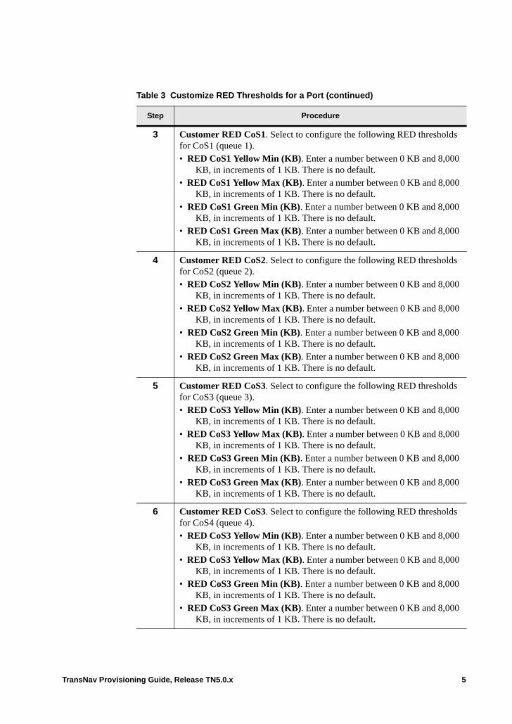
3 Customer RED CoS1. Select to configure the following RED thresholds for CoS1 (queue 1).• RED CoS1 Yellow Min (KB). Enter a number between 0 KB and 8,000
KB, in increments of 1 KB. There is no default.• RED CoS1 Yellow Max (KB). Enter a number between 0 KB and 8,000
KB, in increments of 1 KB. There is no default.• RED CoS1 Green Min (KB). Enter a number between 0 KB and 8,000
KB, in increments of 1 KB. There is no default.• RED CoS1 Green Max (KB). Enter a number between 0 KB and 8,000
KB, in increments of 1 KB. There is no default.
4 Customer RED CoS2. Select to configure the following RED thresholds for CoS2 (queue 2).• RED CoS2 Yellow Min (KB). Enter a number between 0 KB and 8,000
KB, in increments of 1 KB. There is no default.• RED CoS2 Yellow Max (KB). Enter a number between 0 KB and 8,000
KB, in increments of 1 KB. There is no default.• RED CoS2 Green Min (KB). Enter a number between 0 KB and 8,000
KB, in increments of 1 KB. There is no default.• RED CoS2 Green Max (KB). Enter a number between 0 KB and 8,000
KB, in increments of 1 KB. There is no default.
5 Customer RED CoS3. Select to configure the following RED thresholds for CoS3 (queue 3).• RED CoS3 Yellow Min (KB). Enter a number between 0 KB and 8,000
KB, in increments of 1 KB. There is no default.• RED CoS3 Yellow Max (KB). Enter a number between 0 KB and 8,000
KB, in increments of 1 KB. There is no default.• RED CoS3 Green Min (KB). Enter a number between 0 KB and 8,000
KB, in increments of 1 KB. There is no default.• RED CoS3 Green Max (KB). Enter a number between 0 KB and 8,000
KB, in increments of 1 KB. There is no default.
6 Customer RED CoS3. Select to configure the following RED thresholds for CoS4 (queue 4).• RED CoS3 Yellow Min (KB). Enter a number between 0 KB and 8,000
KB, in increments of 1 KB. There is no default.• RED CoS3 Yellow Max (KB). Enter a number between 0 KB and 8,000
KB, in increments of 1 KB. There is no default.• RED CoS3 Green Min (KB). Enter a number between 0 KB and 8,000
KB, in increments of 1 KB. There is no default.• RED CoS3 Green Max (KB). Enter a number between 0 KB and 8,000
KB, in increments of 1 KB. There is no default.
Table 3 Customize RED Thresholds for a Port (continued)
Step Procedure
TransNav Provisioning Guide, Release TN5.0.x 5

7 Click Done to close the dialog box and return to the main screen.
8 The Customize RED Thresholds procedure is complete.
Table 3 Customize RED Thresholds for a Port (continued)
Step Procedure
6 TransNav Provisioning Guide, Release TN5.0.x
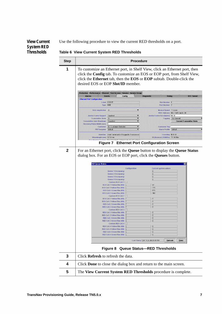
View Current System RED Thresholds
Use the following procedure to view the current RED thresholds on a port.
Table 6 View Current System RED Thresholds
Step Procedure
1 To customize an Ethernet port, in Shelf View, click an Ethernet port, then click the Config tab. To customize an EOS or EOP port, from Shelf View, click the Ethernet tab, then the EOS or EOP subtab. Double-click the desired EOS or EOP Slot/ID member.
Figure 7 Ethernet Port Configuration Screen
2 For an Ethernet port, click the Queue button to display the Queue Status dialog box. For an EOS or EOP port, click the Queues button.
Figure 8 Queue Status—RED Thresholds
3 Click Refresh to refresh the data.
4 Click Done to close the dialog box and return to the main screen.
5 The View Current System RED Thresholds procedure is complete.
TransNav Provisioning Guide, Release TN5.0.x 7

8 TransNav Provisioning Guide, Release TN5.0.x
Chapter 56 Service Endpoints
Introduction This document summarizes the valid source and destination information for each supported service type on the Traverse:• Endpoints for SONET-STS Services• Starting STS Numbers for SONET Services• Endpoints for VT1.5 Services• Endpoints for SONET VT-MUX Services• Endpoints for SONET Services on EoPDH Cards• Endpoints for VC3 and VC4 Services• Starting AUG1 Numbers for VC-3 Services• Endpoints for SDH VC-MUX Services• Endpoints for VC11 and VC12 Services• Endpoints for SDH Services on EoPDH Cards• Ethernet Service Member Types
TransNav Provisioning Guide, Release TN5.0.x 1

Endpoints for SONET-STS Services
The following table lists valid sources and destinations for STS services for the following cards: NGE, NGE Plus, 10GbE, and GbE-10. Your network may require creating multiple services at multiple nodes.
Note: For information on the valid sources and destinations for SONET services on EoPDH cards, see Endpoints for SONET Services on EoPDH Cards.
The Traverse system supports multicast STS connections for 1+1 path-protected and drop-and-continue services.
Table 1 Endpoints for STS Services
Sources Destinations
Port Type Mapping Port Type Mapping
OC-N1 node/slot/port/sts STM-N (HO - high order)STM-N (LO - low order)
all ports E1 card
OC-NEC1DS3CCDS3TMXall ports DS1 card
node/slot/port/aug1/node/slot/port/aug1/vc3node/slot/port/aug1/tug3/vc3node/slot
node/slot/port/stsnode/slot/port/stsnode/slot/portnode/slot/portnode/slot/portnode/slot
EC1 node/slot/port STM-N (HO)STM-N (LO)
OC-NEC1DS3CC
node/slot/port/aug1/node/slot/port/aug1/vc3node/slot/port/aug1/tug3/vc3
node/slot/port/stsnode/slot/port/stsnode/slot/portnode/slot/port
DS3CC node/slot/port STM-N (HO)STM-N (LO)
OC-NEC1DS3CC
node/slot/port/aug1/node/slot/port/aug1/vc3node/slot/port/aug1/tug3/vc3
node/slot/port/stsnode/slot/port/stsnode/slot/portnode/slot/port
DS3TMX node/slot/port STM-N (HO)STM-N (LO)
OC-N
node/slot/port/aug1/node/slot/port/aug1/vc3node/slot/port/aug1/tug3/vc3
node/slot/port/stsnode/slot/port/sts
2 TransNav Provisioning Guide, Release TN5.0.x
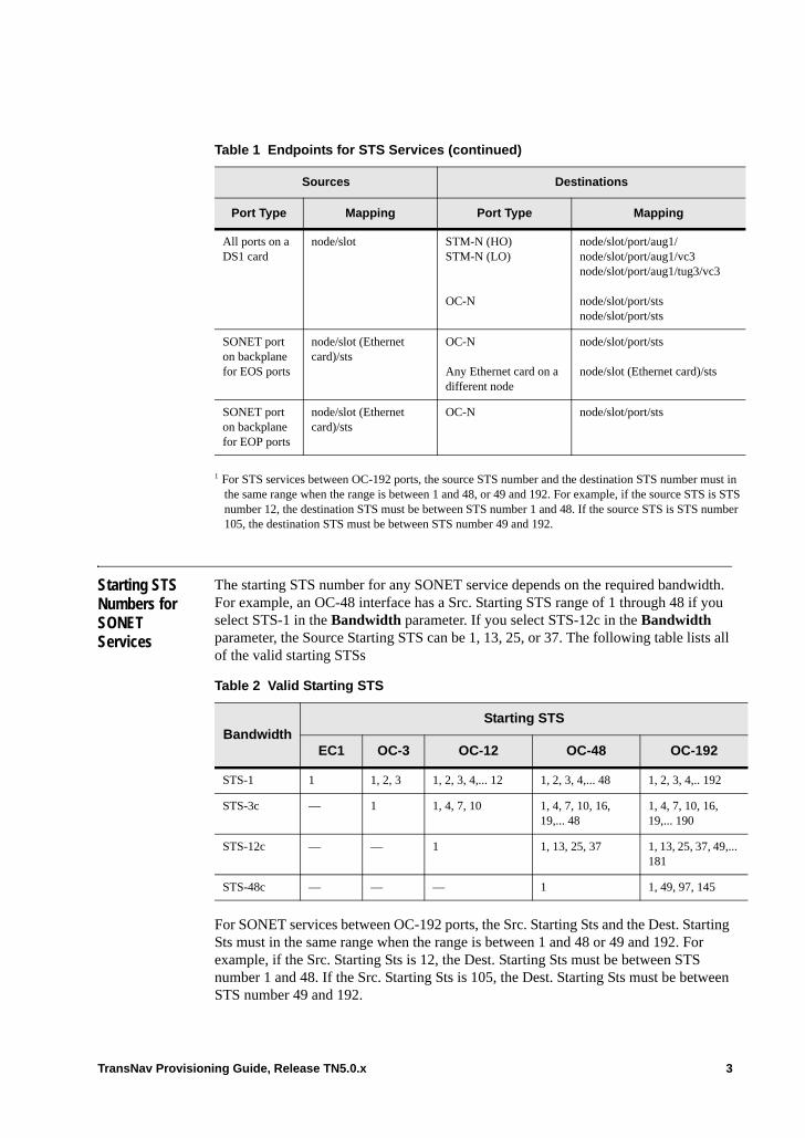
Starting STS Numbers for SONET Services
The starting STS number for any SONET service depends on the required bandwidth. For example, an OC-48 interface has a Src. Starting STS range of 1 through 48 if you select STS-1 in the Bandwidth parameter. If you select STS-12c in the Bandwidth parameter, the Source Starting STS can be 1, 13, 25, or 37. The following table lists all of the valid starting STSs
For SONET services between OC-192 ports, the Src. Starting Sts and the Dest. Starting Sts must in the same range when the range is between 1 and 48 or 49 and 192. For example, if the Src. Starting Sts is 12, the Dest. Starting Sts must be between STS number 1 and 48. If the Src. Starting Sts is 105, the Dest. Starting Sts must be between STS number 49 and 192.
All ports on a DS1 card
node/slot STM-N (HO)STM-N (LO)
OC-N
node/slot/port/aug1/node/slot/port/aug1/vc3node/slot/port/aug1/tug3/vc3
node/slot/port/stsnode/slot/port/sts
SONET port on backplane for EOS ports
node/slot (Ethernet card)/sts
OC-N
Any Ethernet card on a different node
node/slot/port/sts
node/slot (Ethernet card)/sts
SONET port on backplane for EOP ports
node/slot (Ethernet card)/sts
OC-N node/slot/port/sts
1 For STS services between OC-192 ports, the source STS number and the destination STS number must in the same range when the range is between 1 and 48, or 49 and 192. For example, if the source STS is STS number 12, the destination STS must be between STS number 1 and 48. If the source STS is STS number 105, the destination STS must be between STS number 49 and 192.
Table 1 Endpoints for STS Services (continued)
Sources Destinations
Port Type Mapping Port Type Mapping
Table 2 Valid Starting STS
BandwidthStarting STS
EC1 OC-3 OC-12 OC-48 OC-192
STS-1 1 1, 2, 3 1, 2, 3, 4,... 12 1, 2, 3, 4,... 48 1, 2, 3, 4,.. 192
STS-3c — 1 1, 4, 7, 10 1, 4, 7, 10, 16, 19,... 48
1, 4, 7, 10, 16, 19,... 190
STS-12c — — 1 1, 13, 25, 37 1, 13, 25, 37, 49,... 181
STS-48c — — — 1 1, 49, 97, 145
TransNav Provisioning Guide, Release TN5.0.x 3
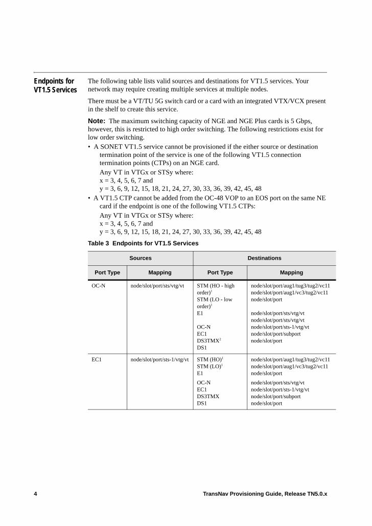
Endpoints for VT1.5 Services
The following table lists valid sources and destinations for VT1.5 services. Your network may require creating multiple services at multiple nodes.
There must be a VT/TU 5G switch card or a card with an integrated VTX/VCX present in the shelf to create this service.
Note: The maximum switching capacity of NGE and NGE Plus cards is 5 Gbps, however, this is restricted to high order switching. The following restrictions exist for low order switching. • A SONET VT1.5 service cannot be provisioned if the either source or destination
termination point of the service is one of the following VT1.5 connection termination points (CTPs) on an NGE card. Any VT in VTGx or STSy where:x = 3, 4, 5, 6, 7 andy = 3, 6, 9, 12, 15, 18, 21, 24, 27, 30, 33, 36, 39, 42, 45, 48
• A VT1.5 CTP cannot be added from the OC-48 VOP to an EOS port on the same NE card if the endpoint is one of the following VT1.5 CTPs: Any VT in VTGx or STSy where:x = 3, 4, 5, 6, 7 andy = 3, 6, 9, 12, 15, 18, 21, 24, 27, 30, 33, 36, 39, 42, 45, 48
Table 3 Endpoints for VT1.5 Services
Sources Destinations
Port Type Mapping Port Type Mapping
OC-N node/slot/port/sts/vtg/vt STM (HO - high order)1
STM (LO - low order)1
E1
OC-NEC1DS3TMX2
DS1
node/slot/port/aug1/tug3/tug2/vc11node/slot/port/aug1/vc3/tug2/vc11node/slot/port
node/slot/port/sts/vtg/vtnode/slot/port/sts/vtg/vtnode/slot/port/sts-1/vtg/vtnode/slot/port/subportnode/slot/port
EC1 node/slot/port/sts-1/vtg/vt STM (HO)1
STM (LO)1
E1
OC-NEC1DS3TMXDS1
node/slot/port/aug1/tug3/tug2/vc11node/slot/port/aug1/vc3/tug2/vc11node/slot/port
node/slot/port/sts/vtg/vtnode/slot/port/sts-1/vtg/vtnode/slot/port/subportnode/slot/port
4 TransNav Provisioning Guide, Release TN5.0.x
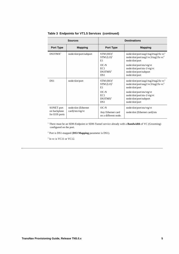
DS3TMX2 node/slot/port/subport STM (HO)1
STM (LO)1
E1
OC-NEC1DS3TMX2
DS1
node/slot/port/aug1/tug3/tug2/lo vc3
node/slot/port/aug1/vc3/tug2/lo vc3
node/slot/port
node/slot/port/sts/vtg/vtnode/slot/port/sts-1/vtg/vtnode/slot/port/subportnode/slot/port
DS1 node/slot/port STM (HO)1
STM (LO)1
E1
OC-NEC1DS3TMX2
DS1
node/slot/port/aug1/tug3/tug2/lo vc3
node/slot/port/aug1/vc3/tug2/lo vc3
node/slot/port
node/slot/port/sts/vtg/vtnode/slot/port/sts-1/vtg/vtnode/slot/port/subportnode/slot/port
SONET port on backplane for EOS ports
node/slot (Ethernet card)/sts/vtg/vt
OC-N
Any Ethernet card on a different node.
node/slot/port/sts/vtg/vt
node/slot (Ethernet card)/sts
1 There must be an SDH-Endpoint or SDH-Tunnel service already with a Bandwidth of VC (Grooming) configured on the port.
2 Port is DS1-mapped (DS3 Mapping parameter is DS1).
3 lo vc is VC11 or VC12.
Table 3 Endpoints for VT1.5 Services (continued)
Sources Destinations
Port Type Mapping Port Type Mapping
TransNav Provisioning Guide, Release TN5.0.x 5
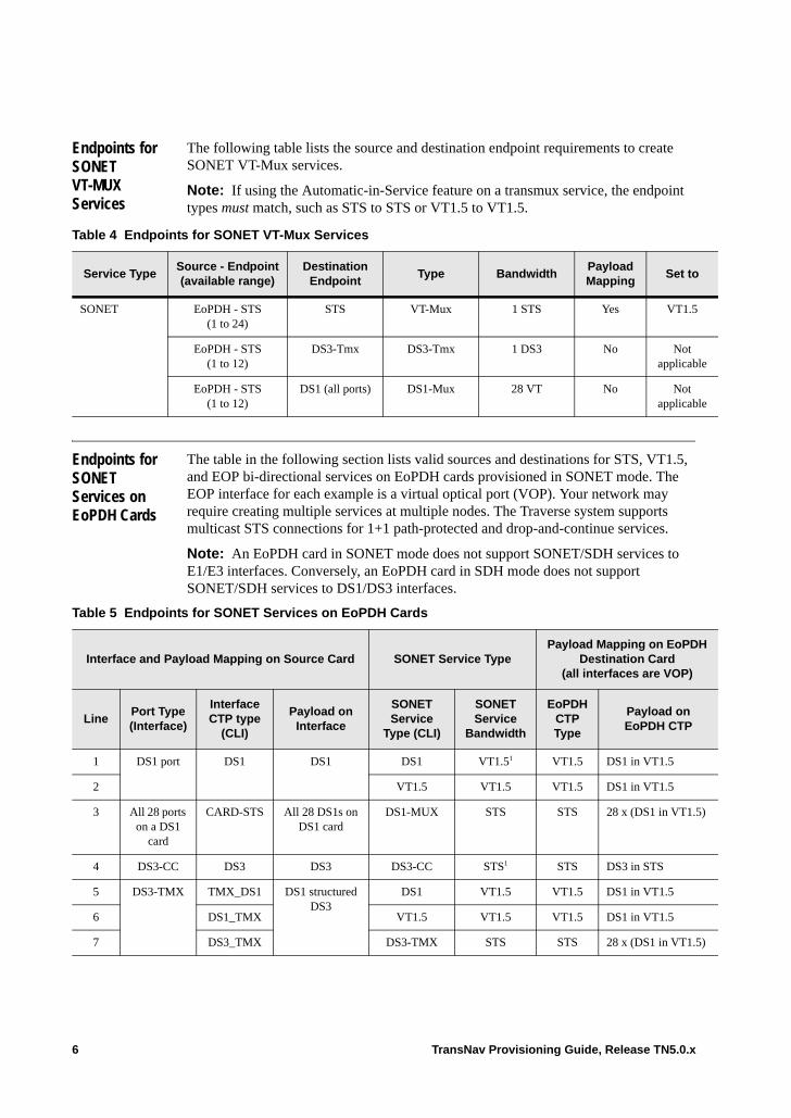
Endpoints for SONET VT-MUX Services
The following table lists the source and destination endpoint requirements to create SONET VT-Mux services.
Note: If using the Automatic-in-Service feature on a transmux service, the endpoint types must match, such as STS to STS or VT1.5 to VT1.5.
Endpoints for SONET Services on EoPDH Cards
The table in the following section lists valid sources and destinations for STS, VT1.5, and EOP bi-directional services on EoPDH cards provisioned in SONET mode. The EOP interface for each example is a virtual optical port (VOP). Your network may require creating multiple services at multiple nodes. The Traverse system supports multicast STS connections for 1+1 path-protected and drop-and-continue services.
Note: An EoPDH card in SONET mode does not support SONET/SDH services to E1/E3 interfaces. Conversely, an EoPDH card in SDH mode does not support SONET/SDH services to DS1/DS3 interfaces.
Table 4 Endpoints for SONET VT-Mux Services
Service TypeSource - Endpoint(available range)
Destination Endpoint
Type BandwidthPayload Mapping
Set to
SONET EoPDH - STS(1 to 24)
STS VT-Mux 1 STS Yes VT1.5
EoPDH - STS(1 to 12)
DS3-Tmx DS3-Tmx 1 DS3 No Not applicable
EoPDH - STS(1 to 12)
DS1 (all ports) DS1-Mux 28 VT No Not applicable
Table 5 Endpoints for SONET Services on EoPDH Cards
Interface and Payload Mapping on Source Card SONET Service TypePayload Mapping on EoPDH
Destination Card (all interfaces are VOP)
LinePort Type (Interface)
Interface CTP type
(CLI)
Payload on Interface
SONET Service
Type (CLI)
SONET Service
Bandwidth
EoPDH CTP Type
Payload on EoPDH CTP
1 DS1 port DS1 DS1 DS1 VT1.51 VT1.5 DS1 in VT1.5
2 VT1.5 VT1.5 VT1.5 DS1 in VT1.5
3 All 28 ports on a DS1
card
CARD-STS All 28 DS1s on DS1 card
DS1-MUX STS STS 28 x (DS1 in VT1.5)
4 DS3-CC DS3 DS3 DS3-CC STS1 STS DS3 in STS
5 DS3-TMX TMX_DS1 DS1 structured DS3
DS1 VT1.5 VT1.5 DS1 in VT1.5
6 DS1_TMX VT1.5 VT1.5 VT1.5 DS1 in VT1.5
7 DS3_TMX DS3-TMX STS STS 28 x (DS1 in VT1.5)
6 TransNav Provisioning Guide, Release TN5.0.x
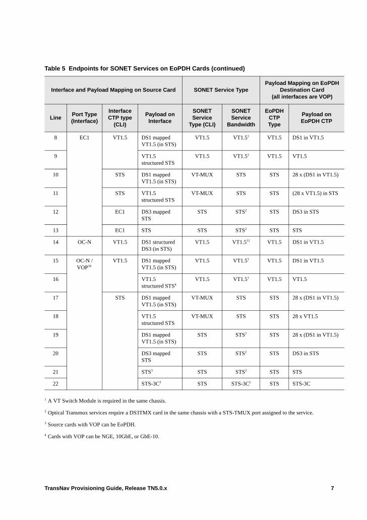
8 EC1 VT1.5 DS1 mapped VT1.5 (in STS)
VT1.5 VT1.51 VT1.5 DS1 in VT1.5
9 VT1.5 structured STS
VT1.5 VT1.51 VT1.5 VT1.5
10 STS DS1 mapped VT1.5 (in STS)
VT-MUX STS STS 28 x (DS1 in VT1.5)
11 STS VT1.5 structured STS
VT-MUX STS STS (28 x VT1.5) in STS
12 EC1 DS3 mapped STS
STS STS2 STS DS3 in STS
13 EC1 STS STS STS2 STS STS
14 OC-N VT1.5 DS1 structured DS3 (in STS)
VT1.5 VT1.512 VT1.5 DS1 in VT1.5
15 OC-N / VOP34
VT1.5 DS1 mapped VT1.5 (in STS)
VT1.5 VT1.51 VT1.5 DS1 in VT1.5
16 VT1.5 structured STS4
VT1.5 VT1.51 VT1.5 VT1.5
17 STS DS1 mapped VT1.5 (in STS)
VT-MUX STS STS 28 x (DS1 in VT1.5)
18 VT1.5 structured STS
VT-MUX STS STS 28 x VT1.5
19 DS1 mapped VT1.5 (in STS)
STS STS2 STS 28 x (DS1 in VT1.5)
20 DS3 mapped STS
STS STS2 STS DS3 in STS
21 STS3 STS STS2 STS STS
22 STS-3C3 STS STS-3C2 STS STS-3C
1 A VT Switch Module is required in the same chassis.
2 Optical Transmux services require a DS3TMX card in the same chassis with a STS-TMUX port assigned to the service.
3 Source cards with VOP can be EoPDH.
4 Cards with VOP can be NGE, 10GbE, or GbE-10.
Table 5 Endpoints for SONET Services on EoPDH Cards (continued)
Interface and Payload Mapping on Source Card SONET Service TypePayload Mapping on EoPDH
Destination Card (all interfaces are VOP)
LinePort Type (Interface)
Interface CTP type
(CLI)
Payload on Interface
SONET Service
Type (CLI)
SONET Service
Bandwidth
EoPDH CTP Type
Payload on EoPDH CTP
TransNav Provisioning Guide, Release TN5.0.x 7
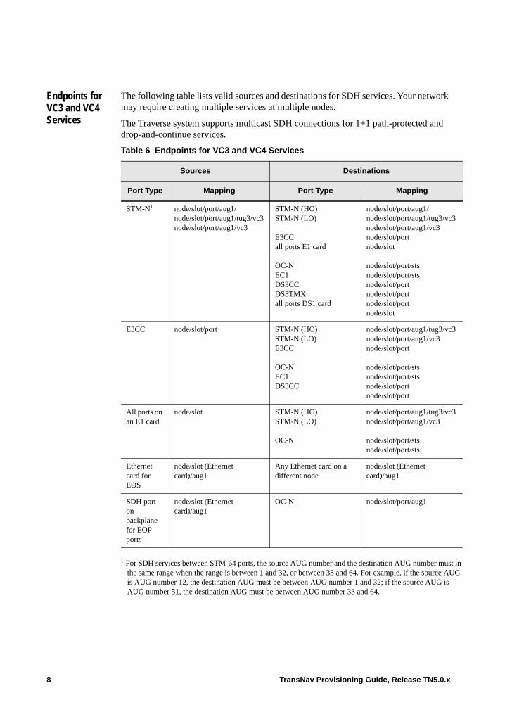
Endpoints for VC3 and VC4 Services
The following table lists valid sources and destinations for SDH services. Your network may require creating multiple services at multiple nodes.
The Traverse system supports multicast SDH connections for 1+1 path-protected and drop-and-continue services.
Table 6 Endpoints for VC3 and VC4 Services
Sources Destinations
Port Type Mapping Port Type Mapping
STM-N1
1 For SDH services between STM-64 ports, the source AUG number and the destination AUG number must inthe same range when the range is between 1 and 32, or between 33 and 64. For example, if the source AUGis AUG number 12, the destination AUG must be between AUG number 1 and 32; if the source AUG is AUG number 51, the destination AUG must be between AUG number 33 and 64.
node/slot/port/aug1/node/slot/port/aug1/tug3/vc3node/slot/port/aug1/vc3
STM-N (HO)STM-N (LO)
E3CCall ports E1 card
OC-NEC1DS3CCDS3TMXall ports DS1 card
node/slot/port/aug1/node/slot/port/aug1/tug3/vc3node/slot/port/aug1/vc3node/slot/portnode/slot
node/slot/port/stsnode/slot/port/stsnode/slot/portnode/slot/portnode/slot/portnode/slot
E3CC node/slot/port STM-N (HO)STM-N (LO)E3CC
OC-N EC1DS3CC
node/slot/port/aug1/tug3/vc3node/slot/port/aug1/vc3node/slot/port
node/slot/port/stsnode/slot/port/stsnode/slot/portnode/slot/port
All ports on an E1 card
node/slot STM-N (HO)STM-N (LO)
OC-N
node/slot/port/aug1/tug3/vc3node/slot/port/aug1/vc3
node/slot/port/stsnode/slot/port/sts
Ethernet card for EOS
node/slot (Ethernet card)/aug1
Any Ethernet card on a different node
node/slot (Ethernet card)/aug1
SDH port on backplane for EOP ports
node/slot (Ethernet card)/aug1
OC-N node/slot/port/aug1
8 TransNav Provisioning Guide, Release TN5.0.x
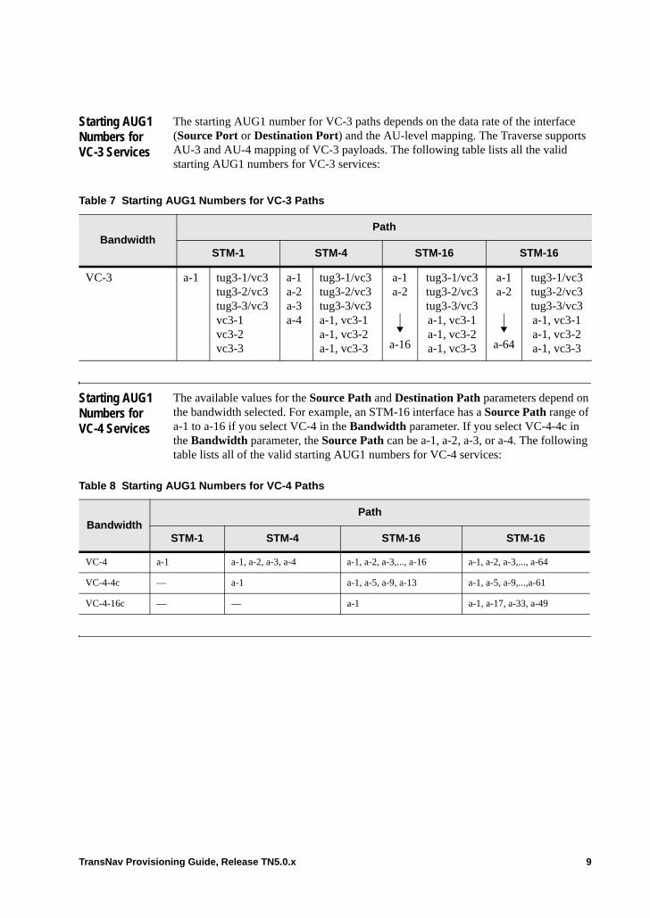
Starting AUG1 Numbers for VC-3 Services
The starting AUG1 number for VC-3 paths depends on the data rate of the interface (Source Port or Destination Port) and the AU-level mapping. The Traverse supports AU-3 and AU-4 mapping of VC-3 payloads. The following table lists all the valid starting AUG1 numbers for VC-3 services:
Starting AUG1 Numbers for VC-4 Services
The available values for the Source Path and Destination Path parameters depend on the bandwidth selected. For example, an STM-16 interface has a Source Path range of a-1 to a-16 if you select VC-4 in the Bandwidth parameter. If you select VC-4-4c in the Bandwidth parameter, the Source Path can be a-1, a-2, a-3, or a-4. The following table lists all of the valid starting AUG1 numbers for VC-4 services:
Table 7 Starting AUG1 Numbers for VC-3 Paths
BandwidthPath
STM-1 STM-4 STM-16 STM-16
VC-3 a-1 tug3-1/vc3tug3-2/vc3tug3-3/vc3vc3-1vc3-2vc3-3
a-1a-2a-3a-4
tug3-1/vc3tug3-2/vc3tug3-3/vc3a-1, vc3-1a-1, vc3-2a-1, vc3-3
a-1a-2
a-16
tug3-1/vc3tug3-2/vc3tug3-3/vc3a-1, vc3-1a-1, vc3-2a-1, vc3-3
a-1a-2
a-64
tug3-1/vc3tug3-2/vc3tug3-3/vc3a-1, vc3-1a-1, vc3-2a-1, vc3-3
Table 8 Starting AUG1 Numbers for VC-4 Paths
BandwidthPath
STM-1 STM-4 STM-16 STM-16
VC-4 a-1 a-1, a-2, a-3, a-4 a-1, a-2, a-3,..., a-16 a-1, a-2, a-3,..., a-64
VC-4-4c — a-1 a-1, a-5, a-9, a-13 a-1, a-5, a-9,...,a-61
VC-4-16c — — a-1 a-1, a-17, a-33, a-49
TransNav Provisioning Guide, Release TN5.0.x 9
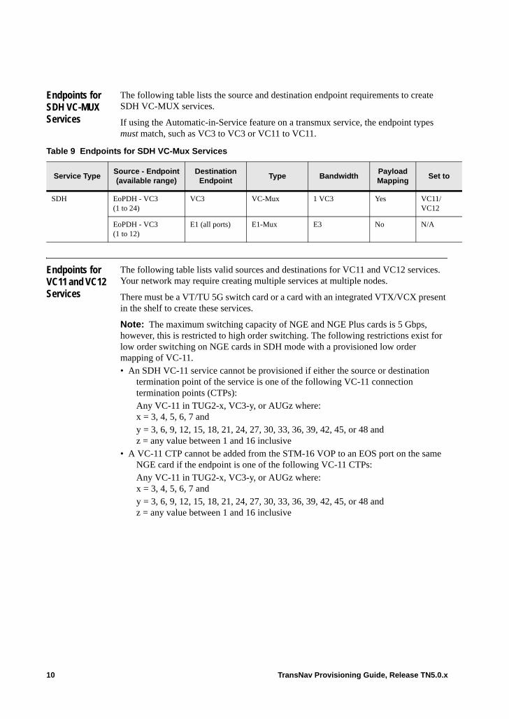
Endpoints for SDH VC-MUX Services
The following table lists the source and destination endpoint requirements to create SDH VC-MUX services.
If using the Automatic-in-Service feature on a transmux service, the endpoint types must match, such as VC3 to VC3 or VC11 to VC11.
Endpoints for VC11 and VC12 Services
The following table lists valid sources and destinations for VC11 and VC12 services. Your network may require creating multiple services at multiple nodes.
There must be a VT/TU 5G switch card or a card with an integrated VTX/VCX present in the shelf to create these services.
Note: The maximum switching capacity of NGE and NGE Plus cards is 5 Gbps, however, this is restricted to high order switching. The following restrictions exist for low order switching on NGE cards in SDH mode with a provisioned low order mapping of VC-11. • An SDH VC-11 service cannot be provisioned if either the source or destination
termination point of the service is one of the following VC-11 connection termination points (CTPs):Any VC-11 in TUG2-x, VC3-y, or AUGz where:x = 3, 4, 5, 6, 7 andy = 3, 6, 9, 12, 15, 18, 21, 24, 27, 30, 33, 36, 39, 42, 45, or 48 andz = any value between 1 and 16 inclusive
• A VC-11 CTP cannot be added from the STM-16 VOP to an EOS port on the same NGE card if the endpoint is one of the following VC-11 CTPs: Any VC-11 in TUG2-x, VC3-y, or AUGz where:x = 3, 4, 5, 6, 7 andy = 3, 6, 9, 12, 15, 18, 21, 24, 27, 30, 33, 36, 39, 42, 45, or 48 andz = any value between 1 and 16 inclusive
Table 9 Endpoints for SDH VC-Mux Services
Service TypeSource - Endpoint(available range)
Destination Endpoint
Type BandwidthPayload Mapping
Set to
SDH EoPDH - VC3 (1 to 24)
VC3 VC-Mux 1 VC3 Yes VC11/ VC12
EoPDH - VC3(1 to 12)
E1 (all ports) E1-Mux E3 No N/A
10 TransNav Provisioning Guide, Release TN5.0.x

• No restrictions exist for VC-12 connection termination points on NGE cards.
Table 10 Endpoints for VC11 and VC12 Services
Sources Destinations
Port Type Mapping Port Type Mapping
STM-N1
1 There must be an SDH-Endpoint or SDH-Tunnel service already with a Bandwidth of VC (Grooming) configured on the port.
node/slot/port/aug1/tug3/tug2/lovc2
node/slot/port/aug1/vc3/tug2/lovc2
2 lo vc is VC11 or VC12.
STM (HO)1
STM (LO)1
E1
OC-NEC1DS3TMX3
DS1
3 Port is E1-mapped (DS3 Mapping parameter is E1).
node/slot/port/aug1/tug3/tug2/lo vc2
node/slot/port/aug1/vc3/tug2/lo vcc
node/slot/port
node/slot/port/sts/vtg/vtnode/slot/port/sts-1/vtg/vtnode/slot/port/sts-1/vtg/vtnode/slot/port/subportnode/slot/port
DS3TMX3 node/slot/port/subport STM (HO)1
STM (LO)1
E1
OC-N EC1DS3TMX3
DS1
node/slot/port/aug1/tug3/tug2/lo vc2
node/slot/port/aug1/vc3/tug2/lo vc1
node/slot/port
node/slot/port/sts/vtg/vtnode/slot/port/sts/vtg/vtnode/slot/port/sts-1/vtg/vtnode/slot/port/subportnode/slot/port
E1 node/slot/port STM (HO)1
STM (LO)1
E1
OC-N EC1DS3TMX3
DS1
node/slot/port/aug1/tug3/tug2/lo vc2
node/slot/port/aug1/vc3/tug2/lo vc2
node/slot/port
node/slot/port/sts/vtg/vtnode/slot/port/sts/vtg/vtnode/slot/port/sts-1/vtg/vtnode/slot/port/subportnode/slot/port
DS1 node/slot/port STM node/slot/port/aug1/tug3/tug2/lo vc2
node/slot/port/aug1/vc3/tug2/lo vc2
TransNav Provisioning Guide, Release TN5.0.x 11

Endpoints for SDH Services on EoPDH Cards
The following table lists valid sources and destinations for SDH services on EoPDH cards. The Traverse system supports multicast STM connections for 1+1 path-protected and drop-and-continue services.
Note: An EoPDH card in SDH mode does not support SONET/SDH services to DS1/DS3 interfaces. Conversely, an EoPDH card in SONET mode does not support SONET/SDH services to E1/E3 interfaces.
Table 11 Endpoints for SDH Services on EoPDH Cards
Interface and Payload Mapping on Source Card SDH Service TypePayload mapping on
EoPDH Destination Card (all interfaces are VOP)
LIne Port Type (Interface)
Interface CTP type
(CLI)
Payload on Interface
SDH Service
Type (CLI)
SDH Service
Bandwidth
EoPDH CTP Type
Payload on EoPDH CTP
1 E1 port E1 E1 E1 VC121 VC12 E1 in VC12 (in VC3)
2 All 21 ports on an E1 card
CARD-STM All 21 E1s on card
E1-MUX HO-VC3 VC-3 21 x (E1 in VC12) in VC3
3 E3-CC E3 E3 E3-CC HO-VC32 VC-3 E3 in VC3
4 DS3-TMX E1_TMX E1 structured DS3
E1 VC121 VC12 E1 in VC12 (in VC3)
5 DS3-TMX DS1_TMX_IN_VC12
E1 structured DS3
VC12 VC121 VC12 E1 in VC12 (in VC3)
6 STM-N VC12 E1 structured DS3 in VC3
VC121 3 VC12 E1 in VC12 (in VC3)
7 VC3 E1 structured DS3 in VC3
VC3 HO-VC33 VC3 21 x (E1 in VC12)
8 E1 structured DS3 in VC3
LO-VC33 4 21 x (E1 in VC12)
9 E3 mapped VC3 LO-VC34 E3 (in VC3)
10 VC36 LO-VC34 VC3
12 TransNav Provisioning Guide, Release TN5.0.x

11 STM-N / VOP5
VC11 VC11 structured VC36
VC11 VC111 VC11 VC11 (in VC3)
12 VC12 E1 mapped VC12 (in VC3)
VC12 VC121 VC12 E1 in VC12 (in VC3)
13 VC12 structured VC36
VC121 VC12 VC12 (in VC3)
14 VC3 VC11 structured VC3
VC-MUX HO-VC3 VC3 28 x VC-11
15 E1 mapped VC12 (in VC3)
HO-VC3 21 x (E1 in VC12)
16 VC12 structured VC3
HO-VC3 21 X VC-12
17 E3 mapped VC3 VC3 HO-VC32 E3 (in VC3)
18 VC36 HO-VC32 VC3
19 STM-N / VOP5
VC4 VC46 VC4 VC42 VC4 VC4
1 A TU Switch card must be in the same chassis.
2 For end-to-end services, the two cards of the service (EoPDH and another card) can be in different nodes.
3 Optical Transmux services require a DS3TMX card in the same chassis with a STS-TMUX port assigned to the service.
4 LO-VC3 services can be created from VC4-VC3 or VC4-Grooming endpoints on the Source card.
5 Source cards with VOP can be EoPDH.
6 Source cards with VOP can be NGE, 10GbE, or GbE-10.
Table 11 Endpoints for SDH Services on EoPDH Cards (continued)
Interface and Payload Mapping on Source Card SDH Service TypePayload mapping on
EoPDH Destination Card (all interfaces are VOP)
LIne Port Type (Interface)
Interface CTP type
(CLI)
Payload on Interface
SDH Service
Type (CLI)
SDH Service
Bandwidth
EoPDH CTP Type
Payload on EoPDH CTP
TransNav Provisioning Guide, Release TN5.0.x 13
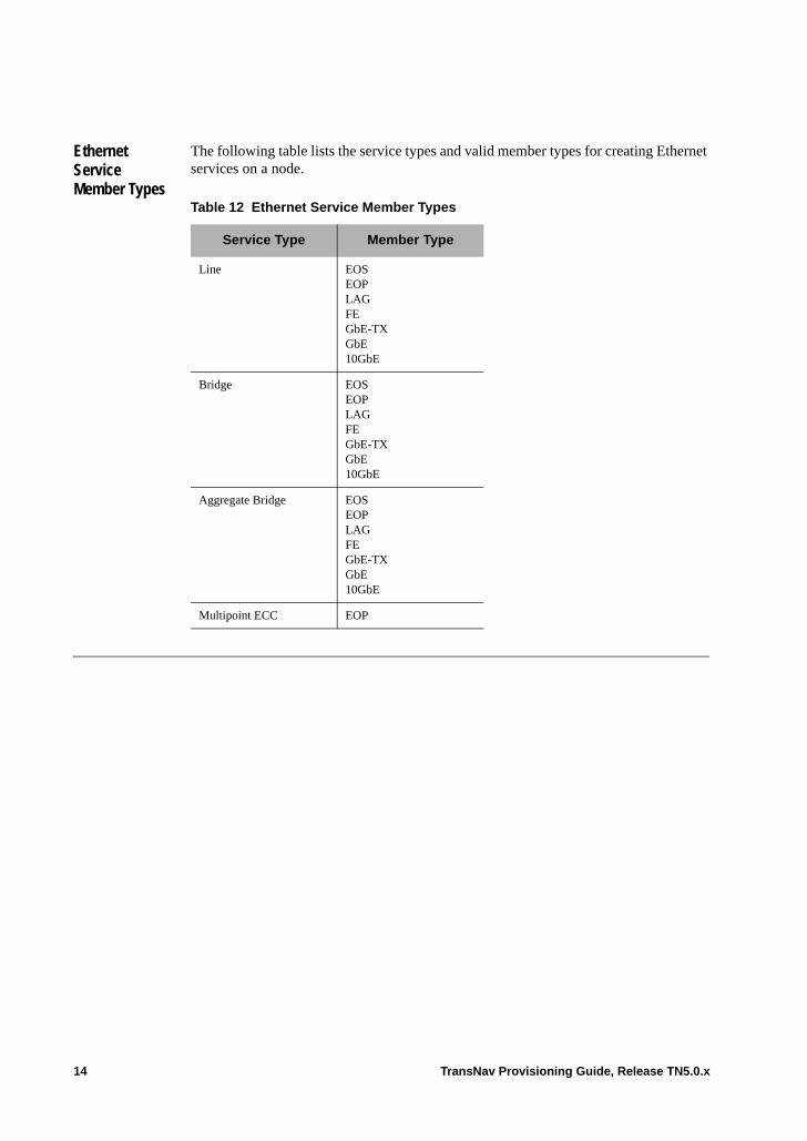
Ethernet Service Member Types
The following table lists the service types and valid member types for creating Ethernet services on a node.
Table 12 Ethernet Service Member Types
Service Type Member Type
Line EOSEOPLAGFEGbE-TXGbE10GbE
Bridge EOSEOPLAGFEGbE-TXGbE10GbE
Aggregate Bridge EOSEOPLAGFEGbE-TXGbE10GbE
Multipoint ECC EOP
14 TransNav Provisioning Guide, Release TN5.0.x
Chapter 57 Provisioning Checklists
Introduction Use the checklists in this Appendix to bring a Traverse network into service and to create services for transport over the network using the TransNav management system graphical user interface (GUI). • Node and Timing Configuration Checklist• Card Configuration Checklist• Protection Group Configuration Checklist• Port Configuration Checklist• Service Creation Checklist
Successfully completing each checklist assumes that the tasks in the previous checklist are complete.
Each step references the related detail-level procedure for additional information.
TransNav Provisioning Guide, Release TN5.0.x 1
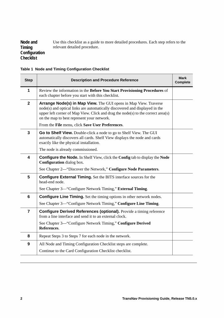
Node and Timing Configuration Checklist
Use this checklist as a guide to more detailed procedures. Each step refers to the relevant detailed procedure.
Table 1 Node and Timing Configuration Checklist
Step Description and Procedure ReferenceMark
Complete
1 Review the information in the Before You Start Provisioning Procedures of each chapter before you start with this checklist.
2 Arrange Node(s) in Map View. The GUI opens in Map View. Traverse node(s) and optical links are automatically discovered and displayed in the upper left corner of Map View. Click and drag the node(s) to the correct area(s) on the map to best represent your network.
From the File menu, click Save User Preferences.
3 Go to Shelf View. Double-click a node to go to Shelf View. The GUI automatically discovers all cards. Shelf View displays the node and cards exactly like the physical installation.
The node is already commissioned.
4 Configure the Node. In Shelf View, click the Config tab to display the Node Configuration dialog box.
See Chapter 2—“Discover the Network,” Configure Node Parameters.
5 Configure External Timing. Set the BITS interface sources for the head-end node.
See Chapter 3—“Configure Network Timing,” External Timing.
6 Configure Line Timing. Set the timing options in other network nodes.
See Chapter 3—“Configure Network Timing,” Configure Line Timing.
7 Configure Derived References (optional). Provide a timing reference from a line interface and send it to an external clock.
See Chapter 3—“Configure Network Timing,” Configure Derived References.
8 Repeat Steps 3 to Steps 7 for each node in the network.
9 All Node and Timing Configuration Checklist steps are complete.
Continue to the Card Configuration Checklist checklist.
2 TransNav Provisioning Guide, Release TN5.0.x
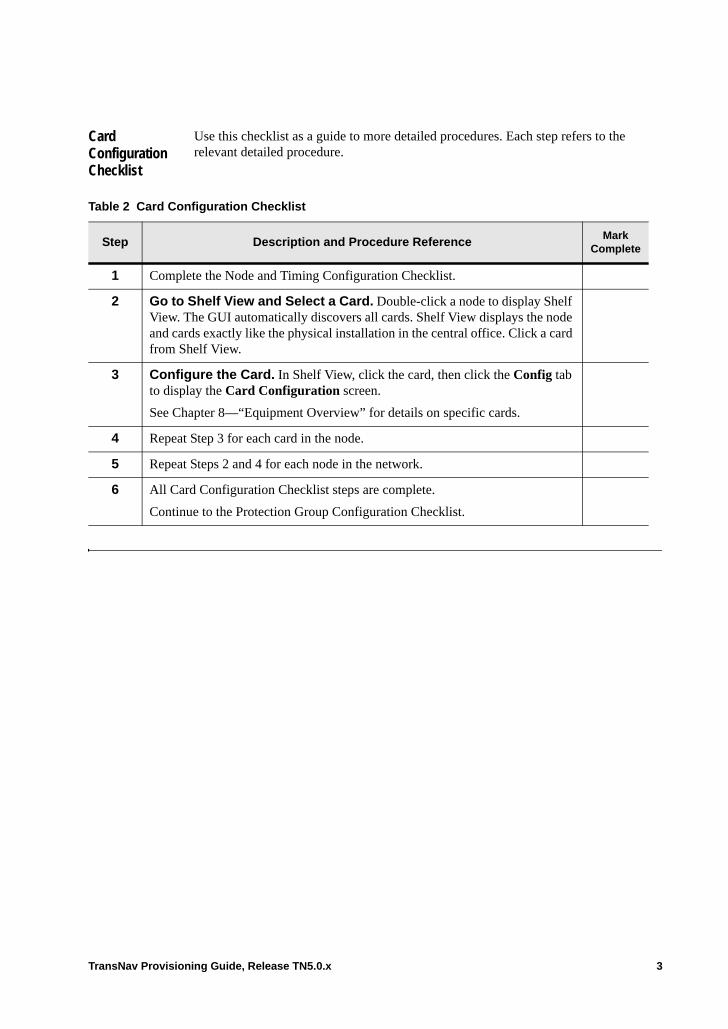
Card Configuration Checklist
Use this checklist as a guide to more detailed procedures. Each step refers to the relevant detailed procedure.
Table 2 Card Configuration Checklist
Step Description and Procedure ReferenceMark
Complete
1 Complete the Node and Timing Configuration Checklist.
2 Go to Shelf View and Select a Card. Double-click a node to display Shelf View. The GUI automatically discovers all cards. Shelf View displays the node and cards exactly like the physical installation in the central office. Click a card from Shelf View.
3 Configure the Card. In Shelf View, click the card, then click the Config tab to display the Card Configuration screen.
See Chapter 8—“Equipment Overview” for details on specific cards.
4 Repeat Step 3 for each card in the node.
5 Repeat Steps 2 and 4 for each node in the network.
6 All Card Configuration Checklist steps are complete.
Continue to the Protection Group Configuration Checklist.
TransNav Provisioning Guide, Release TN5.0.x 3

Protection Group Configuration Checklist
Use this checklist as a guide to more detailed procedures. Each step refers to the relevant detailed procedure. Complete each item as required for your network configuration.
Table 3 Protection Group Configuration Checklist
Step Description and Procedure ReferenceMark
Complete
1 Complete the Card Configuration Checklist.
2 Create Equipment Protection Groups for Tributary Cards. For each tributary card, create an equipment protection group.
See Chapter 18—“Creating Equipment Protection Groups,” Create an Equipment Protection Group.
3 Create 1+1 APS Groups for Tributary OC-N Cards. (SONET only.) For each tributary OC-N port, create a facility protection group.
See Chapter 20—“Creating a 1+1 APS/MSP Protection Group,” Create a 1+1 APS/MSP Protection Group.
4 Create 1:1 Equipment Protection Group for VCX Hardware. (SDH only.) If you have a card with a VCX component, create a protection group for the VCX hardware.
See Chapter 20—“Creating a 1+1 APS/MSP Protection Group,” Create a 1+1 APS/MSP Protection Group
5 Create 1+1 MSP Groups for Tributary STM-N Cards. (SDH only.) For each tributary STM-N port, create a facility protection group.
See Chapter 20—“Creating a 1+1 APS/MSP Protection Group,” Create a 1+1 APS/MSP Protection Group.
6 Create 1+1 Protection Group for Trunk Cards. For a point-to-point network, create a 1+1 APS/MSP protection groups for trunk links.
See Chapter 20—“Creating a 1+1 APS/MSP Protection Group.”
7 Create UPSR Ring Topology. For a path-protected ring network, create a UPSR ring topology.
See Chapter 17—“Creating and Maintaining UPSR or SNCP Ring Protection Groups,” Create a UPSR or SNCP Ring Protection Group.
8 Create a BLSR Topology. For a line-protected ring network, create a BLSR topology.
See Chapter 16—“Creating a BLSR/MS-SPRing Protection Group,” Create a BLSR or MS-SPRing Protection Group.
9 All Protection Group Configuration Checklist steps are complete.
Continue to Port Configuration Checklist.
4 TransNav Provisioning Guide, Release TN5.0.x

Port Configuration Checklist
Use this checklist as a guide to more detailed procedures. Each step refers to the relevant detailed procedure. Complete the steps as required based on the cards installed in the shelf.
Table 4 Port Configuration Checklist
Step Description and Procedure ReferenceMark
Complete
1 Complete the Protection Group Configuration Checklist.
2 In Shelf View, click any port, then click the Config tab.
3 On the Port Configuration screen, change any default values for any configurable parameters.
See Chapter 8—“Equipment Overview” for details on all configurable port parameters.
SDH or SONET Interfaces:
If this is a SONET or SDH interface, configure parameters only on the working port if the port is part of a protection group. Parameters on a protecting port are automatically set to the same values as the working port.
Electrical Interfaces:
If this is an electrical interface, configure parameters only on working cards if a card is configured as part of a protection group. Parameters on a protecting card are automatically set to the same values as the working card.
4 Click the Lock icon, which is located in the lower left corner of the screen, to unlock the port and monitor potential problems. To automatically suppress port-level service affecting alarms and performance monitoring when services are not active, enable the Automatic in Service parameter.
5 Click Apply to save the changes.
6 Repeat Steps 1 through 5 for each node in the network.
7 All Port Configuration Checklist steps are complete.
Continue to Service Creation Checklist.
TransNav Provisioning Guide, Release TN5.0.x 5
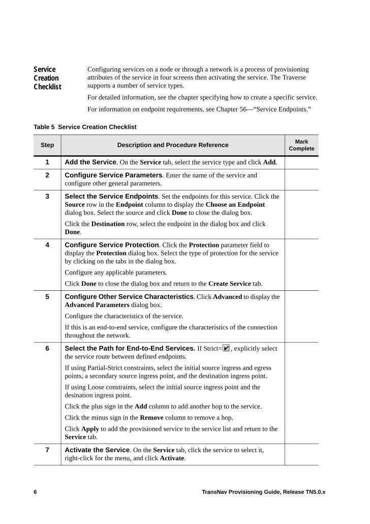
Service Creation Checklist
Configuring services on a node or through a network is a process of provisioning attributes of the service in four screens then activating the service. The Traverse supports a number of service types.
For detailed information, see the chapter specifying how to create a specific service.
For information on endpoint requirements, see Chapter 56—“Service Endpoints.”
Table 5 Service Creation Checklist
Step Description and Procedure ReferenceMark
Complete
1 Add the Service. On the Service tab, select the service type and click Add.
2 Configure Service Parameters. Enter the name of the service and configure other general parameters.
3 Select the Service Endpoints. Set the endpoints for this service. Click the Source row in the Endpoint column to display the Choose an Endpoint dialog box. Select the source and click Done to close the dialog box.
Click the Destination row, select the endpoint in the dialog box and click Done.
4 Configure Service Protection. Click the Protection parameter field to display the Protection dialog box. Select the type of protection for the service by clicking on the tabs in the dialog box.
Configure any applicable parameters.
Click Done to close the dialog box and return to the Create Service tab.
5 Configure Other Service Characteristics. Click Advanced to display the Advanced Parameters dialog box.
Configure the characteristics of the service.
If this is an end-to-end service, configure the characteristics of the connection throughout the network.
6 Select the Path for End-to-End Services. If Strict= , explicitly select the service route between defined endpoints.
If using Partial-Strict constraints, select the initial source ingress and egress points, a secondary source ingress point, and the destination ingress point.
If using Loose constraints, select the initial source ingress point and the desination ingress point.
Click the plus sign in the Add column to add another hop to the service.
Click the minus sign in the Remove column to remove a hop.
Click Apply to add the provisioned service to the service list and return to the Service tab.
7 Activate the Service. On the Service tab, click the service to select it, right-click for the menu, and click Activate.
6 TransNav Provisioning Guide, Release TN5.0.x
INDEX
Numerics
1+1 APS/MSP2-port OC-48/SMT-16
protection group, 31+1 optimized protection
protection switch priorities, 51+1 path protection
bookend application, 11create service, 9requirements
bookend application, 12procedures, 10service, 9
A
Addlink
destination, 12source, 12
nodeto ring, 1
Administrative stateBITS timing, 5
AINS, see Automatic in ServiceAIS
formatSTS1TMX port, 12
maskSTS1TMX port, 12
Alarmsavailability status
effect on, 3Application
DCSmulti-shelf example, 2single-shelf example, 6
Auditservice availability, see Service
AUG1 numbersstarting
VC3 paths, 9VC4 paths, 9
Auto-discoverydelete link, 15nodes, 1
configuring, 1pre-provisioned nodes, 8
Automatic in Service, 6
configureports, 1
overviewservices, 6
reporting timesetting
servicesavailable on, 7
Auto-negotiationdescription, 17Ethernet
port, 19Availability status
alarmeffect, 3
Available bandwidthlink
view, 14
B
Bandwidthport
virtual, 4profile
create, 5examples, 3policer, 8values, 2
BER thresholdsSTM path
change, 13STS path
change, 26Bi-directional switching
creating, 1BITS timing
administrative state, 5clock quality, 2Config tab, 3force switch command, 9, 10lockout switch command, 9, 10manual switch command, 9, 10
BLSR ringconfiguration
protection, east port, 9protection, west port, 8
delete, 6edit, 6
TransNav Management System Provisioning Guide, Release TN5.0.x 7
protectionhigh order end-to-end services, 5
protection switch commandsforced, 10manual, 10
protection switch priorities, 10remove node, 9squelch table, 9synchronize, 9, 6
Bookend application, 11Bundling
customer-tagged, 3VLAN, 3
Bytesforwarded
transparent services, 2, 3
C
CAC, see Connection admission controlCard
add, 8configuration checklist, 3configuring
working card, 1delete, 9parameters
change, 6common, 3GCM specific, 5when to change, 1
replace, 10Carrier Ethernet Protection Pair
definition, 3description, 1guidelines, 2LAG, 4
support, 3line protection, 4link
aggregation, 3integrity, caution with removal, 8
path protection, 5protection group
create, 4Change
card parameters, 6DCC tunnel, 3DS1 mapping, 7DS1 port parameters, 11
Checklistcard configuration, 3node and timing configuration, 2port configuration, 5
protection group configuration, 4provisioning, 1service creation, 6
Class of serviceassign
untagged packets, 3colors
initial drop precedence, 2use in, 1
port-based, 3queuing policy, 4
Classifierconfigure
guidelines, 4Clock mode, timing, 2Clock quality, timing, 2Colors
class of serviceuse in, 1
Config tabBITS and derived DS1, 3node, 3
Configurationderived references, 19external timing, 15line timing, 18network timing guidelines, 14node parameters, 4timing options global, 14
Connectionsadmission control
Ethernet, 8timing
inputs and outputs, 14Control data
disableSONET, 5third-party equipment, 6
CPE, see Customer premise equipmentCreate
node, 2service
1+1 path protection, 9transparent service, 3
Cross-connectADM service types, 5
Customerpremise equipment, 6
EoPDH applications, 1Customer premise equipment
Ethernet configurationflow chartprocedure guideline, 12
8 TransNav Management System Provisioning Guide, Release TN5.0.x

D
Daylight Saving Timesupport, 1
DCC tunnelchange, 3configuration, 6example, 2requirements, 3
DCSapplication
creating multi-shelf, 6example, multi-shelf, 2example, single-shelf, 6multi-shelf example, 2
DCS-384application, 3definition, 3description, 1guidelines, create, 6minimum configuration, 6MSAID allocation, 11MSAID assignment, 9preprovision order, 3protection groups, 7
DCS-768application, 4description, 1guidelines, create, 6minimum configuration, 6MSAID assignment, 9preprovision order, 4protection group, pre-provisioned, 4protection groups, 7
DCS-96definition, 7guidelines, create, 2MSAID assignment, 3MSAID assignment, details, 4services, create, 8
DCS-IOdefinition, 5MSAID allocation, 2MSAID assignment, 3protection groups, 7
DCS-NGdefinition, 4MSAID allocation, 11
MSAIDrequirements, 7
MSAID allocationdefinition, 8
MSAID assignmentDCS-384, 25
DCS-NG, 25MSAID assignment details, 5multi-shelf
application, create, 8description, 1guidelines, create, 6
servicesactivate DCS-384, 24activate DCS-NG, 24create DCS-384, 21create DCS-NG, 21
Deletenode, 7
Derivedreferences configuration, 19timing, 14
discovers, 1Discovery, see Auto-discoveryDrop and continue service
Ethernet, 6guidelines, 7interconnected rings
guidelines, 7required parameters, 8required procedures, 7requirements, 6video broadcast, 6
DS1mapping
change formats, 5port
change parameters, 2configure, 8requirements, 2
DS1 portcard configuration, 5change parameters, 11
DS3 clear channelport
configure, 11DS3 mapping
STS1TMX port, 12DS3TMX
portconfigure, 15configure subport, 19
E
E1card
mapping, 4VC mapping formats, 3
configure
TransNav Management System Provisioning Guide, Release TN5.0.x 9
mapping formats, 7port
configurePort
configureE1, 8
E3 clear channelport
configure, 10EC1
portconfigure, 21
ECC, see Multipoint ECCEndpoint
resource advisory, 2SDH, 8services
EoPDH cards, 6SDH on EoPDH cards, 12
summary, 1endpoint requirements
optical transmux, 6End-to-end service
high orderBLSR ring, available protection, 5
EOPconnection requirements, 1EoPDH, 4
port member, 5port
create, 8MAC address, 32traffic management, 6
EoPDHbandwidth
requirements, 5customer
premise equipment, 6definition, 1endpoints, 6
SDH services, 12EOP
available port members, 2connection requirements, 1
multipoint ECC, 2port
create, 8EOP, 4members, 5virtual, 4
servicemultipoint, 6restrictions, 6
SDH restrictions, 12SONET/SDH restrictions, 7
termination points, 5VCAT
requirements, 2EOS
bandwidthsvirtual ports, 4
definition, 2links
removing LCAS-enabled, 6port
MAC address, 32queue, 33status, 16threshold, 11
Equipmentcreate
preprovision, 1creating and deleting, 1
Equipment protectionswitch commands, 9switch priorities, 9
Etherchannel, see LAGEthernet
cardconfigure, 3
Carrier Ethernet Protection Paircreate, 4definition, 3
control channelservices, 6
control channel interfaceport member, 7use of, 7
EoPDHport, 4port member, 4
featuresconnection admission control, 8LCAS, 1RSTP, 2video broadcast, 6virtual concatenation, 3
line service, 3link
status, 29link aggregation
capacity changes, 3Carrier Ethernet Protection Pair, 3description, 1guidelines, 2
MAC address, 3
10 TransNav Management System Provisioning Guide, Release TN5.0.x

over SONET/SDHrequired connections, 2
portauto-negotiation, 19configure parameters, 6diagnostic parameters, 27link integrity, 7SFP/XFP transceiver, 25status, view, 29
see also Carrier Ethernet Protection Pairservice
end-to-end, 1OAM see Service, OAM
traffic managementdescription, 4EOP ports, 6
virtual portEoPDH, 4
VLANtagging guidelines, 7
Externaltiming
configuration, 15
F
Force switch commandBITS timing, 9, 10
Forced protection switch commandBLSR ring, 10
G
G.747services
standard, 2GCM
config tab, 5parameter
specific, 5
H
Hop-by-hopservice, 8
I
Iconlink
off page connector, 12physical link, 13
InteroperabilityTE-206
with TE-100, 6
with Traverse, 6IP QoS, 1
access control list, 5configuring, 3static classifiers, 4
L
LACP, see LAGLAG
capacity changes, 3CEPP, 4create, 5
LACP, 5description, 1guidelines, 2LACP
configure, 6definition, 2
LCASEOS links
removal guidelines, 6TE-206, 6
feature description, 1Line
formatSTS1TMX port, 12
protectionCarrier Ethernet Protection Pair, 4
servicedefinition, 3
timingconfiguration, 18
Line timingconfiguration, 6source, 7SSM (synchronization status messages)
received, 7transmitted, 7
status, 7Timing tab, 6
Linkadd, 11available bandwidth
view, 14delete, 15destination, 12integrity
card removal, cautions, 8off page connector icon, 12operational state, 13set without DCC discovery, 12source, 12types, 12
TransNav Management System Provisioning Guide, Release TN5.0.x 11
data rate, 13Link Aggregation Control Protocol see LAGLockout protection switch command
BITS timing, 9Lockout switch command
BITS timing, 10
M
MA see Service, OAM domain structureMAC address
EOP port, 32EOS port, 32Ethernet, 3forwarding
multipoint service, 6table
view or edit, 30Maintenance
association see Service, OAM domain structureendpoint see Service, OAM domain structureintermediate point see Service, OAM domain
structureManagement
gateway node, 1Manual
protection switch commandBLSR ring, 10
Manual switch commandBITS timing, 9, 10
Mapping formatsDS1
change parameters, 5Menus
TE-50, 5MEP see Service, OAM domain structureMIP see Service, OAM domain structureModule
add, 8delete, 9replace, 10
MSAIDallocation
DCS-384 shelf, 11DCS-IO, 2DCS-IO shelf, 14DCS-NG shelf, 11definition, 8
assignmentactivating DCS-IO, 20DCS-384, 25DCS-384 shelf, 9DCS-768 shelf, 9DCS-96 details, 4
DCS-96 shelf, 3DCS-IO, 16DCS-NG, 25definition, 8
definition, 7formats
definition, 9supported formats, 9
MS-SP ringconfiguration
protection, east port, 9protection, west port, 8
delete, 6edit, 6protection switch commands
forced, 10manual, 10
protection switch priorities, 10remove node, 9squelch table, 9synchronize, 9, 6
Multipoint ECCEoPDH
create, 2service
description, 6
N
Networkconfiguration process, 1Time Protocol, 5timing configuration guidelines, 14
Nodeauto-discovery, 1create, 2delete, 7
pre-provisioned, 8name requirements, 2parameters
configure, 4configuring, 3
preprovisioningadd name, 2
Proxy ARPsetting, 7
timing configuration checklist, 2NTP IP, see Network Time Protocol
O
OC-192uplinks
protected services, 4
12 TransNav Management System Provisioning Guide, Release TN5.0.x

OC-482-port
protection groups, 3OC-48/STM-16
2-port1+1 APS/MSP protection group, 3UPSR/SNCP protection group, 3
Opticaltransmux
endpoint requirements, Automatic in Service, 6provision guidelines, 9required service procedures, 9service creation requirements, 8
Optical transmux, 1
P
Parameterscommon, 3drop and continue service, 8
Pathprotection
Carrier Ethernet Protection Pair, 5over MSP-protected links, 7, 8
Pause controlTraverse, 8
Payload mappinghigh order services
SONET, 6SDH services, 7
Performance monitoringtemplate
source, 2PLCT Threshold
EOS portadvanced, 11
Policersalgorithm, 7bandwidth profiles, 8create
Ethernet cards, 9guidelines, 8
description, 6Policing
egress portsavailable on, 8
Portcommon
parameters, 3configuration
checklist, 5configure
DS1, 8DS3CC, 11
DS3TMX, 15DS3TMX subport, 19E3 clear channel, 10EC1, 21SONET, 28STM-N, 15STS1TMX, 15
protectionoptical GbE overview, 2
virtualbandwidth, 4
Preprovisioningcreating and deleting managed objects, 1delete
nodes, 8node name, 2node type, 2
Primaryreference
timing, 14Priorities
priority requestsequipment protection, 9
protection switching1+1 APS, 101+1 optimized protection, 5BLSR ring, 10equipment protection, 9
Protected servicescreate, 1guidelines, 2
ProtectionBLSR ring
east port, 9high order end-to-end protection, 5west port, 8
groupCarrier Ethernet Protection Pair, 4
groupsDCS-384, pre-provisioned, 7DCS-768, pre-provisioned, 7DCS-IO, 7
MS-SP ringeast port, 9west port, 8
ringsdelete, 6edit, 6synchronize, 6
switch commands1+1 optimized protection, 5
Protection groups1+1 APS/MSP
TransNav Management System Provisioning Guide, Release TN5.0.x 13
2-port OC-48/STM-16, 32-port OC-48, 3configuration
checklist, 4UPSR/SNCP
2-port OC-48/STM-16, 3Protection switch commands
BLSR ringforced, 10manual, 10
forcedBLSR ring, 10
manualBLSR ring, 10
MS-SP ringforced, 10manual, 10
Provisioningchecklists, 1
Proxy ARPnode set up, 7
Q
Quality of REStiming tab, 2
Queuing policytraffic
management, 9
R
Random early discardconfiguration
defaults, 3description, 1thresholds
customize, 4view, 7
weightcurve, 1curve for GbE-10/10GbE cards, 2
RED, see Random early discardReplace card
cautionslink integrity and CEPP, 8
Requirementsdrop and continue service, 6optical transmux service, 8
Resourceadvisory
definition, 2link, 14
RSTP
feature description, 2TE-206
disabling LCAS, 6virtual
bridge, 7description, 7multiple copies
S
SDHequipment requirements, 2service
endpoints, 8Security
warningsetting node specific, 7
Serviceaggregate
guidelines, 6OC-48 UPSR, 5
alarm managementdisable, behavior, 6disabling, effect of, 4
automatic, see Automatic in Serviceavailabilty status, 3
audit, 6creation checklist, 6deactivating
EOS links with LCAS, 6drop-and-continue services, 1endpoints, 1EoPDH
restrictions, 7, 6, 12Ethernet
configuration guidelines, 2determining, 8MAC address forwarding, 6multipoint control channel, 6OAM MEP directionality, 4
high orderpayload mapping, 6
hop-by-hop, 8multipoint, 6OAM
configuring, 6description, 1domain structure, 2maintenance association, create, 6maintenance association, edit, 13maintenance endpoint, create, 9maintenance endpoint, edit, 17maintenance intermediate point, create, 9maintenance intermediate point, view, 14
14 TransNav Management System Provisioning Guide, Release TN5.0.x
overview, 2probes, 20probes, creating, 21
parametersadvanced, 11protection, configure, 7source PM template, 2
protected uplinks, 4SDH
endpoints, 8payload mapping, 7
switchDS1, 3DS1 traffic, 13E1, 4
tabfields, 1shortcut menu, 6
transparentSDH example, 3SONET example, 2
VC-MUXprovisioning, 6
VT MUXendpoint requirements, 6SDH endpoints, 10
VT-MUXprovisioning SONET, 6
Service parametersendpoints
summary, 1Services
activateDCS-384, 24DCS-NG, 24
createDCS-96, 8
grouping, 7multipoint ECC
create, 2resize columns, 7search
filters, 8sorting, 7
SFPsEthernet
port parameters, 25Shelf view
shortcut menu, 8SNCP ring
delete, 6edit, 6synchronize, 6
SONETport
configuration, 37configure, 28
Sourceline timing, 7PM template, 2
SSM (synchronization status messages)ignore received, 2received by line timing, 7transmitted by line timing, 7
Static routeadd to node, 3
Statusline timing, 7
STM-64uplinks
protected services, 4STM-N
portconfigure, 15
STS1TMXport
AIS format, 12AIS mask, 12configure, 15DS3 mapping, 12line format, 12subport mapping, 12subport numbering, 12
Sub shelfmenu
launch sub shelf, TransAccess 200 Mux, 9options, 7
Subportmapping
STS1TMX port, 12numbering
STS1TMX port, 12Summary
service endpoints, 1Switching
bi-directional, 1capacity
slot-to-slot, 2Synchronization
BLSR ring, 9MS-SP ring, 9
T
TaggingVLAN
definition, 2
TransNav Management System Provisioning Guide, Release TN5.0.x 15
TE-206nodes
discovering, 2RSTP interoperability, 6
TE-50menu
options, 5Templates
createclassifier, 5
Third-party equipmentdisable control data, 6
Timesetting
zone, 6Timing
clock mode, 2configuration, 2
BITS and derived DS1, 3description, 1line timing, 6
connections, 14derived, 14example, 12external
parameters, 3global option, 14mode, 2Quality of RES, 2tab
description, 2line timing, 6
Topologyupdate, 13, 7
add note to ring, 3diagram, 1
Trafficmanagement
auto-negotiation, 8broadcast storm control defined, 7description, 4EOP ports, 6marking packets, 12maximum information rate, 7pause control, 8policer description, 6policing description, 1preventing network loops, 11queuing policy, 9queuing priority, 10queuing schedule, 10reception behavior, 2setting bandwidth, 10
transmission behavior, 3TransAccess 200 Mux
detach, 9Transmux
servicecards required, 5configure, 10configure optical attributes, 13provision guidelines, 9required procedures, 9
standardG.747 services, 2
Transparent servicebytes forwarded, 2, 3cards required, 4create, 3, 1, 4disable control data parameter, 6guidelines, 5provision, 7SDH example, 3SONET example, 2
Typologyupdate
add node to protection group, 7
U
Updatetopology, 13, 7
Uplinksprotected services, 4
UPSR ringdelete, 6edit, 6synchronize, 6
UPSR/SNCP2-port OC-48/STM-16
protection group, 3
V
VCAT, see Virtual concatenationVideo broadcast
configuration, 6Viewing
MAC address table, 30VLAN usage, 19
Virtualconcatenation
descriptionPDH circuits, 2
RSTPdescription, 7
VLAN
16 TransNav Management System Provisioning Guide, Release TN5.0.x
bundlingcustomer-tagged, 3definition, 3determining service, 8
concurrent port IDscard support, 7
reserved IDs, 7supported combinations, 7tag
system behavior, 6tagging
Ethernet ports, 6tagging guidelines
Ethernet, 7tags
definition, 2view usage, 19
VRB, see Virtual RSTPVT MUX
serviceendpoint requirements, 6SDH endpoints, 10
X
XFPsEthernet
port parameters, 25
TransNav Management System Provisioning Guide, Release TN5.0.x 17