Embed Size (px)
Citation preview

3.1 2012 Transmission Line Rebuild NP 2012 CBA
2012 Transmission Line Rebuild
June 2011
Prepared by:
Brian Combden
Approved by:
Michael Comerford P.Eng.
NEWFOUNDLAND F :
A FORTIS COMPANY

3.1 2012 Transmission Line Rebuild NP 2012 CBA
i
Table of Contents
Page
1.0 Transmission Line Rebuild Strategy ................................................................................... 1
2.0 Transmission Line Rebuild Projects Planned for 2012....................................................... 1
2.1 Transmission Line 110L ......................................................................................... 1
2.2 Transmission Line 21L…….. ................................................................................. 2
2.3 Transmission Line 124L……… ............................................................................. 3
3.0 Concluding .......................................................................................................................... 4
Appendix A: Transmission Line Rebuild Strategy Schedule
Appendix B: Topographic Maps of Transmission Lines 110L, 21L, and 124L
Appendix C: Photographs of Transmission Lines 110L, 21L, and 124L

3.1 2012 Transmission Line Rebuild NP 2012 CBA
1
1.0 Transmission Line Rebuild Strategy
Transmission lines are the bulk transmitter of electricity providing service to customers.
Transmission lines operate at higher voltages, either 66 kV or 138 kV and are often located
across country away from road right of way.
In 2006, Newfoundland Power (“The Company”) submitted its Transmission Line Rebuild
Strategy outlining a 10-year plan to rebuild aging transmission lines. This plan prioritized the
investment in rebuild projects based on physical condition, risk of failure, and potential customer
impact in the event of a failure.
The Transmission Line Rebuild Strategy is regularly updated to ensure it reflects the latest
reliability data, inspection information and condition assessments.
Appendix A contains the updated Transmission Line Rebuild Strategy Schedule.
2.0 Transmission Line Rebuild Projects Planned for 2012
In 2012, the Company plans to rebuild transmission line 21L and sections of 110L and 124L.
Appendix B contains topographic views of each of the lines to be rebuilt. Appendix C contains
photographs of the existing lines.
By 2012, all of these lines will be in excess of 48 years old. They have deteriorated poles,
crossarms, hardware, and conductor. This makes the lines vulnerable to large scale damage
when exposed to heavy wind, ice, and snow loading, thus increasing the risk of power outages.
Inspections have identified evidence of decaying wood, worn hardware and damage to insulators.
2.1 Transmission Line 110L ($1,853,000)
The Bonavista Peninsula is supplied electricity by two separate transmission lines. The first is
123L, a 138 kV H-Frame transmission line running between Clarenville and Catalina. The
second transmission circuit consists of a pair of 66 kV single pole lines, 110L and 111L. They
run between Clarenville and Lockston and between Lockston and Catalina respectively.
The report Bonavista Loop Transmission Planning, filed with Newfoundland Power’s 2006
Capital Budget Application, compared alternatives for addressing transmission line requirements
on the Bonavista Peninsula. The analysis determined that the rebuilding of 110L and increasing
conductor sizing is the least cost alternative to ensuring the continued provision of safe, reliable
electrical service to the area.
110L was constructed in 1958 and is 79 kilometres in length. It helps service approximately
4,300 customers on the Bonavista Peninsula between Milton and Lockston. This line also
connects the Company’s Lockston hydro plant to the main electricity grid.
Sections of 110L have been upgraded with a total of 52 kilometres rebuilt. Based on the
condition of the remaining sections of the line, it is recommended that 10.3 kilometres be rebuilt

3.1 2012 Transmission Line Rebuild NP 2012 CBA
2
in 2012. The 10.3 kilometres being rebuilt include an 8.7 kilometre section near Lockston
substation and a 1.6 kilometre section on the Trans Canada Highway in Clarenville. The 1.6
kilometre section along the Trans Canada Highway was delayed from 2010 as a result of
Hurricane Igor.1
The conductor on 110L has been subjected to severe ice loading since its original installation and
is damaged and deteriorated. The steel core and the aluminum strands are corroded, decreasing
the physical strength and electrical capacity of the conductor. This deterioration is such that the
line has been de-rated to about one-half of its original electrical current carrying capacity for
safety reasons. Increasing the conductor size on the transmission line, as recommended in the
Bonavista Loop Transmission Planning report, increases the length of time during the year (from
6 weeks to 38 weeks) when 110L can carry the Bonavista Peninsula load with transmission line
123L out of service.
The most recent 2011 inspection of 110L noted the following deficiencies on the 99 structures
comprising the 10.3 kilometre section of line:
Table 1
110L Deficiencies
Deficiency Category
Number of
Structures
Insulators 17
Deteriorated/Damaged Crossarms 9
Pole Deteriorated/Damaged 39
Based on the overall deteriorated conditions observed, it is recommended that this section of line
be rebuilt to current CSA Severe Weather Loading Standards in 2012 at an estimated cost of
$1,653,000.
2.2 Transmission Line 21L ($822,000)
21L is a 66kV H-Frame transmission line running between the Horse Chops Hydroelectric Plant
and transmission line 20L.2 21L connects the Horse Chops plant to the main electricity grid.
3 It
is 5.3 kilometres in length and was originally constructed in 1952. The line consists of 36 two
and three-pole H-Frame structures utilizing 266.8 ACSR conductors, with a number of road
crossing spans along the route.
1 Attempts to reschedule the work on 110L following Hurricane Igor were hampered by increased electrical
loading at that particular time of year thus preventing the project from being completed in 2010. 2 21L terminates at the intersection of Horse Chops Road and the Southern Shore Highway near Cape Broyle.
3 Horse Chops plant produces 42 GWH of electricity annually, or 9.8% of Newfoundland Power’s annual
hydroelectric production

3.1 2012 Transmission Line Rebuild NP 2012 CBA
3
Inspections have identified substantial deterioration due to decay, woodpecker holes, and splits
and checks in the poles, crossarms and crossbraces. Many of these wooden components are in
advanced stages of deterioration and require replacement. Most of the wooden poles are original
vintage (59 years old) and have surpassed their normal life expectancy. Transmission line 21L
also contains insulators manufactured by Canadian Ohio Brass (COB). These insulators are
identified as deficient due to a history of premature failure caused by cement growth. As the
cement expands, cracks in the porcelain insulators occur making them more susceptible to
flashovers.
The poles, crossarms and crossbraces have had their strength compromised due to severe
deterioration. Long span lengths combined with physical condition, make the line susceptible to
damage should it become exposed to wind, ice or snow loading.
Recent inspections have determined the transmission line has reached a point where continued
maintenance is no longer feasible and it has to be rebuilt to continue its safe, reliable operation.
The most recent 2010 inspection of 21L noted the following deficiencies:
Table 2
21L Deficiencies
Deficiency Category
Number of
Structures
Insulators 25
Crossarms Deteriorated/Damaged 7
Crossbraces Deteriorated/Damaged 17
Pole Deteriorated/Damaged 11
Based on the advanced age and overall deteriorated condition observed, it is recommended this
section of line be rebuilt to current CSA Severe Weather Loading Standards in 2012 at an
estimated cost of $822,000.
2.3 Transmission Line 124L ($802,000)
124L is a 138 kV transmission line between Clarenville Substation and Gambo Substation. The
line has a total length of 90 kilometres and is of H-frame wood pole construction. The line was
originally built in 1964.
Due to the elevation and type of terrain in the White Hills area near Clarenville, the line in that
location has had a history of problems. This area is prone to heavy ice loading and high winds.
On several occasions, poles, crossarms and conductors have failed because of the severe weather
conditions.

3.1 2012 Transmission Line Rebuild NP 2012 CBA
4
The transmission line was originally designed to withstand conductor ice loading of 12.7 mm
(½”) of radial ice. Actual accumulation of 38 mm (1½”) has been measured on this line in the
White Hills area. Loading has been severe enough that the conductor in this section of the line
has been permanently stretched, thus increasing the sag of the conductor and decreasing the
ground clearance. In this same area there are several extra long spans which present potential
risks to the line’s structural integrity and of decreased ground clearance.4
During the period 2001 to 2005, a total of 16 kilometres of line were rebuilt between Clarenville
and Thorburn Lake. These upgrades were necessary to correct several ground clearance issues
and addressed line failure in the area caused by severe wind and ice loading. The only remaining
original section of line in that particularly harsh location is the 5 kilometre section planned for
2012.
The most recent 2011 inspection of 124L noted the following deficiencies in the 23 structures
comprising the 5 kilometre section planned for 2012:
Table 3
124L Deficiencies
Deficiency Category
Number of
Structures
Insulators 7
Crossarms Deteriorated/Damaged 4
Crossbraces Deteriorated/Damaged 1
Structures Deteriorated/Damaged 9
Based on the advanced age and overall deteriorated conditions observed, it is recommended that
a 5 kilometre section of line be rebuilt to current CSA Severe Weather Loading Standards in
2012 at an estimated cost of $802,000.
3.0 Concluding
In 2012, the Company will rebuild transmission line 21L and sections of 110L and 124L. These
transmission lines range in age from 47 to 59 years old. Their structures have experienced
deterioration of poles, crossarms, hardware, and conductor. Recent inspections have determined
the transmission lines have reached a point where continued maintenance is no longer feasible
and they have to be rebuilt to continue providing safe, reliable electrical service.
This project is justified based on the need to replace deteriorated transmission line infrastructure
in order to ensure the continued provision of safe, reliable electrical service.
4 This section of 124L has 2 particularly long spans, one that is 1,283 feet and another 1,502 feet in length.

3.1 2012 Transmission Line Rebuild NP 2012 CBA
Appendix A
Transmission Line Rebuild Strategy
Schedule

3.1 2012 Transmission Line Rebuild NP 2012 CBA
A-1
Transmission Line Rebuilds
2017-2023
($000)
Line Year Replacement
Age (Years)
2017 2018 2019 2020 2021 2022 2023
041L CAR-HCT 1958 59 2,557
049L HWD-CHA 1966 55 584
057L BRB-HGR 1958 58 1,655
100L SUN-CLV 1964 57 2,148 2,886 2,065
101L GFS-RBK 1957 61 1,850 4,023
102L GAN-RBK 1958 61 2,012 6,444 4,296
124L CLV-GAM 1964 58 3,634 3,441
146L GAN-GAM 1964 59 2,524
302L SPO-LAU 1959 58 1,508 3,602
403L TAP-ROB 1960 62 890
Average Age at
Replacement
Total 59
$5,720 $5,452 $6,035 $6,444 $7,028 $7,410 $8,030
Transmission Line Rebuilds
2012-2016
($000)
Line Year Replacement
Age (Years) 2012 2013 2014 2015 2016
012L KBR-MUN 1950 63 350 300
013L SJM-SLA 1962 52 605
014L SLA-MUN 1950 66 220
015L SLA-MOL 1958 57 133
018L GOU-GDL 1951 63 790
021L 20L-HCP 1952 60 822
030L RRD-KBR 1959 56 450 440
032L OXP-RRD 1959 56 353
400L BBK-WHE 1967 48 1,940 2,000
057L BRB - HGR 1958 58 1,600
068L HGR-CAR 1951 63 881
069L KEN-SLA 1951 64 830
110L CLV-LOK 1958 54 1,853 2,868
124L CLV-GAM 1964 48 802
Average Age at
Replacement
Total 58
$3,477 $3,218 $2,576 $3,706 $4,260

3.1 2012 Transmission Line Rebuild NP 2012 CBA
Appendix B
Topographic Maps of
Transmission Lines 110L, 21L and 124L

3.1 2012 Transmission Line Rebuild NP 2012 CBA
B-1
Figure 1 – Topographic Map 110L

3.1 2012 Transmission Line Rebuild NP 2012 CBA
B-2
Figure 2 – Topographic Map 21L

3.1 2012 Transmission Line Rebuild NP 2012 CBA
B-3
Figure 3 – Topographic Map 124L

3.1 2012 Transmission Line Rebuild NP 2012 CBA
Appendix C
Photographs of
Transmission Lines
110L, 21L and 124L

3.1 2012 Transmission Line Rebuild NP 2012 CBA
C-1
Transmission Line 110L
Figure 1 – Split Crossarm 110L
Figure 2 – Deteriorated Pole on 110L
3.1 2012 Transmission Line Rebuild NP 2012 CBA
C-2
Figure 3 – Twisted Crossarm 110L
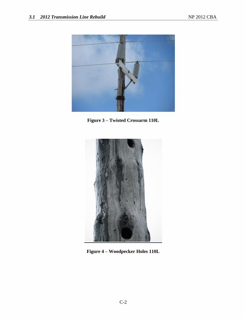
Figure 4 – Woodpecker Holes 110L

3.1 2012 Transmission Line Rebuild NP 2012 CBA
C-3
Figure 5 – Split Pole Top 110L
Figure 6 – Split Pole 110L

3.1 2012 Transmission Line Rebuild NP 2012 CBA
C-4
Transmission Line 21L
Figure 7 – Split Crossbrace 21L
Figure 8 – Pole requiring temporary support 21L

3.1 2012 Transmission Line Rebuild NP 2012 CBA
C-5
Figure 9 – Badly deteriorated pole 21L
Figure 10 – Woodpecker Hole 21L

3.1 2012 Transmission Line Rebuild NP 2012 CBA
C-6
Figure 11 – Deteriorated pole 21L
Figure 12 – Broken and Deteriorated Crossbraces 21L

3.1 2012 Transmission Line Rebuild NP 2012 CBA
C-7
Figure 13 – Deteriorated Pole and Crossarm 21L

3.1 2012 Transmission Line Rebuild NP 2012 CBA
C-8
Transmission Line 124L
Figure 14 – Check in Pole 124L Figure 15 – Woodpecker Holes 124L
Figure 16 – Armour Rod to Repair Wire Damage 124L

3.1 2012 Transmission Line Rebuild NP 2012 CBA
C-9
Figure 17 – Check in Crossarm 124L
Figure 18 – Check in Crossarm 124L

3.1 2012 Transmission Line Rebuild NP 2012 CBA
C-10
Figure 19 – Location with Reduced Ground Clearance 124L