Embed Size (px)
Citation preview

TRANSMISSION & DRIVELINE
C
E
SECTION DLNA
B
LN
DDRIVELINE
F
G
H
I
J
K
L
M
N
O
P
CONTENTS
TRANSFER: TY30A
BASIC INSPECTION .................................... 5
DIAGNOSIS AND REPAIR WORKFLOW .......... 5Work Flow .................................................................5
FUNCTION DIAGNOSIS ............................... 6
4WD SYSTEM ..................................................... 6System Diagram ........................................................6System Description ...................................................8Component Parts Location ......................................10Component Description ...........................................12
DIAGNOSIS SYSTEM (4WD CONTROL UNIT) ..................................................................13
CONSULT-III Function (ALL MODE AWD/4WD) ....13
COMPONENT DIAGNOSIS .........................16
C1201 4WD CONTROL UNIT ............................16Description ..............................................................16DTC Logic ...............................................................16Diagnosis Procedure ...............................................16
C1203 ABS ACTUATOR AND ELECTRIC UNIT (CONTROL UNIT) .....................................17
Description ..............................................................17DTC Logic ...............................................................17Diagnosis Procedure ...............................................17
C1204 4WD SOLENOID .....................................18Description ..............................................................18DTC Logic ...............................................................18Diagnosis Procedure ...............................................18Component Inspection ............................................20
C1205 4WD ACTUATOR RELAY ......................21Description ..............................................................21DTC Logic ...............................................................21Diagnosis Procedure ...............................................21
C1209 MODE SW ..............................................22Description ...............................................................22DTC Logic ................................................................22Diagnosis Procedure ...............................................22Component Inspection .............................................23
C1210 ECM .......................................................25Description ...............................................................25DTC Logic ................................................................25Diagnosis Procedure ...............................................25
C1211 4WD COMMUNICATION .......................26Description ...............................................................26DTC Logic ................................................................26Diagnosis Procedure ...............................................26
C1212 4WD COMMUNICATION .......................28Description ...............................................................28DTC Logic ................................................................28Diagnosis Procedure ...............................................28
U1000 CAN COMM CIRCUIT ...........................30Description ...............................................................30DTC Logic ................................................................30Diagnosis Procedure ...............................................30
U1010 CONTROL UNIT (CAN) .........................31Description ...............................................................31DTC Logic ................................................................31Diagnosis Procedure ...............................................31
POWER SUPPLY AND GROUND CIRCUIT ....32Description ...............................................................32Diagnosis Procedure ...............................................32
4WD WARNING LAMP .....................................34Description ...............................................................34Diagnosis Procedure ...............................................34
4WD INDICATOR LAMP ...................................36Description ...............................................................36Diagnosis Procedure ...............................................36
DLN-1

LOCK INDICATOR LAMP ................................. 37Description .............................................................. 37Diagnosis Procedure .............................................. 37
ECU DIAGNOSIS ........................................ 38
4WD CONTROL UNIT ....................................... 38Reference Value ..................................................... 38Wiring Diagram - 4WD SYSTEM - .......................... 41Fail Safe ................................................................. 44DTC Inspection Priority Chart ................................. 45DTC Index .............................................................. 45
SYMPTOM DIAGNOSIS ............................. 47
4WD SYSTEM SYMPTOMS .............................. 47Symptom Table ...................................................... 47
4WD WARNING LAMP DOES NOT TURN ON ... 48Description .............................................................. 48Diagnosis Procedure .............................................. 48
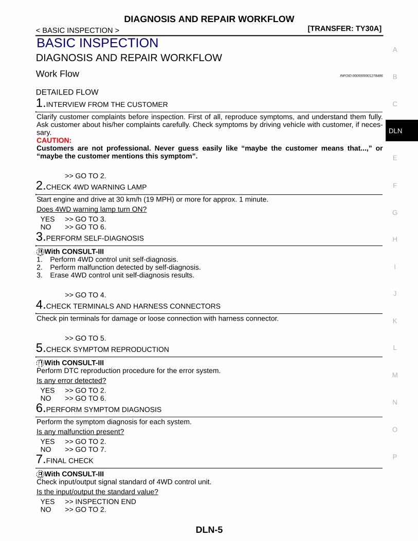
4WD WARNING LAMP DOES NOT TURN OFF .................................................................... 49
Description .............................................................. 49Diagnosis Procedure .............................................. 49
HEAVY TIGHT-CORNER BRAKING SYMP-TOM OCCURS ................................................... 50
Description .............................................................. 50Diagnosis Procedure .............................................. 50
VEHICLE DOES NOT ENTER 4WD MODE ...... 51Description .............................................................. 51Diagnosis Procedure .............................................. 51
4WD WARNING LAMP BLINKS QUICKLY ...... 52Description .............................................................. 52
4WD WARNING LAMP BLINKS SLOWLY ....... 53Description .............................................................. 53Diagnosis Procedure .............................................. 53
NORMAL OPERATING CONDITION ................ 54Description .............................................................. 54
NOISE, VIBRATION AND HARSHNESS (NVH) TROUBLESHOOTING ............................ 55
M/T, A/T ..................................................................... 55M/T, A/T : NVH Troubleshooting Chart ................... 55
CVT ............................................................................ 55CVT : NVH Troubleshooting Chart ......................... 55
PRECAUTION ............................................. 57
PRECAUTIONS ................................................. 57Precaution for Supplemental Restraint System (SRS) "AIR BAG" and "SEAT BELT PRE-TEN-SIONER" ................................................................. 57Precaution for Procedure without Cowl Top Cover ... 57
Service Notice or Precautions for Transfer ............. 57
PREPARATION .......................................... 59
PREPARATION ................................................. 59
M/T, A/T ..................................................................... 59M/T, A/T : Special Service Tools ............................. 59M/T, A/T : Commercial Service Tools ..................... 61
CVT ............................................................................ 62CVT : Special Service Tools ................................... 62CVT : Commercial Service Tools ............................ 64
ON-VEHICLE MAINTENANCE .................. 65
TRANSFER OIL ................................................. 65Inspection ................................................................ 65Draining ................................................................... 65Refilling ................................................................... 65
ON-VEHICLE REPAIR ............................... 66
4WD CONTROL UNIT ....................................... 66
LHD ............................................................................ 66LHD : Exploded View .............................................. 66LHD : Removal and Installation .............................. 66
RHD ........................................................................... 66RHD : Exploded View ............................................. 67RHD : Removal and Installation .............................. 67
REMOVAL AND INSTALLATION .............. 68
TRANSFER ASSEMBLY ................................... 68
MR20DE (M/T), QR25DE (M/T) ................................. 68MR20DE (M/T), QR25DE (M/T) : Exploded View ... 68MR20DE (M/T), QR25DE (M/T) : Removal and In-stallation .................................................................. 68
MR20DE (CVT), QR25DE (CVT) ............................... 69MR20DE (CVT), QR25DE (CVT) : Exploded View ... 69MR20DE (CVT), QR25DE (CVT) : Removal and Installation ............................................................... 69
M9R ........................................................................... 70M9R : Exploded View .............................................. 70M9R : Removal and Installation .............................. 71
DISASSEMBLY AND ASSEMBLY ............ 72
ADAPTER CASE ............................................... 72
M/T, A/T ..................................................................... 72M/T, A/T : Exploded View ....................................... 72M/T, A/T : Disassembly ........................................... 73M/T, A/T : Assembly ................................................ 73M/T, A/T : Inspection After Disassembly ................. 74
CVT ............................................................................ 74CVT : Exploded View .............................................. 75CVT : Disassembly ................................................. 76
DLN-2
C
E
F
G
H
I
J
K
L
M
A
B
LN
N
O
P
D
CVT : Assembly ......................................................76CVT : Inspection After Disassembly ........................77
RING GEAR SHAFT ...........................................78
M/T, A/T .....................................................................78M/T, A/T : Exploded View ........................................78M/T, A/T : Disassembly ...........................................79M/T, A/T : Assembly ................................................80M/T, A/T : Inspection After Disassembly .................81
CVT ............................................................................81CVT : Exploded View ..............................................82CVT : Disassembly ..................................................83CVT : Assembly ......................................................84CVT : Inspection After Disassembly ........................85
DRIVE PINION ....................................................86
M/T, A/T .....................................................................86M/T, A/T : Exploded View ........................................86M/T, A/T : Disassembly ...........................................87M/T, A/T : Assembly ................................................88M/T, A/T : Adjustment .............................................89M/T, A/T : Inspection After Disassembly .................98
CVT ............................................................................98CVT : Exploded View ..............................................99CVT : Disassembly ................................................ 100CVT : Assembly .................................................... 101CVT : Adjustment .................................................. 102CVT : Inspection After Disassembly ...................... 111
TRANSFER CASE ........................................... 112
M/T, A/T ................................................................... 112M/T, A/T : Exploded View ...................................... 112M/T, A/T : Disassembly ......................................... 113M/T, A/T : Assembly .............................................. 113M/T, A/T : Inspection ............................................. 114
CVT .......................................................................... 114CVT : Exploded View ............................................ 115CVT : Disassembly ................................................ 116CVT : Assembly .................................................... 116CVT : Inspection .................................................... 117
SERVICE DATA AND SPECIFICATIONS (SDS) .......................................................... 118
SERVICE DATA AND SPECIFICATIONS (SDS) ................................................................ 118
General Specifications .......................................... 118Preload Torque ..................................................... 118Backlash ................................................................ 118Companion Flange Runout ................................... 118
REAR PROPELLER SHAFT: 3F SPL18-DOJ75
SYMPTOM DIAGNOSIS ............................ 119
NOISE, VIBRATION AND HARSHNESS (NVH) TROUBLESHOOTING ......................... 119
NVH Troubleshooting Chart ..................................119
ON-VEHICLE MAINTENANCE .................. 120
REAR PROPELLER SHAFT ........................... 120Inspection ..............................................................120
ON-VEHICLE REPAIR ............................... 121
REAR PROPELLER SHAFT ........................... 121Exploded View .......................................................121Removal and Installation .......................................121Inspection ..............................................................123
SERVICE DATA AND SPECIFICATIONS (SDS) .......................................................... 124
SERVICE DATA AND SPECIFICATIONS (SDS) ............................................................... 124
General Specifications ...........................................124Propeller Shaft Runout ..........................................124Journal Axial Play ..................................................124
REAR FINAL DRIVE: R145
SYMPTOM DIAGNOSIS ............................ 125
NOISE, VIBRATION AND HARSHNESS (NVH) TROUBLESHOOTING ......................... 125
NVH Troubleshooting Chart ..................................125
PRECAUTION ............................................ 126
PRECAUTIONS ............................................... 126Service Notice or Precautions for Rear Final Drive ..126
PREPARATION ......................................... 127
PREPARATION ............................................... 127Special Service Tools ............................................127Commercial Service Tools .....................................128
FUNCTION DIAGNOSIS ............................ 130
REAR FINAL DRIVE ASSEMBLY .................. 130System Diagram ....................................................130
ON-VEHICLE MAINTENANCE .................. 131
REAR DIFFERENTIAL GEAR OIL ................. 131Inspection ..............................................................131Draining .................................................................131Refilling ..................................................................131
ON-VEHICLE REPAIR ............................... 132
FRONT OIL SEAL ........................................... 132Exploded View .......................................................132Removal and Installation .......................................133
SIDE OIL SEAL ............................................... 135
DLN-3

Exploded View .......................................................135Removal and Installation .......................................135
ELECTRIC CONTROLLED COUPLING ......... 136Exploded View .......................................................136Removal and Installation .......................................137
REMOVAL AND INSTALLATION ..............140
REAR FINAL DRIVE ASSEMBLY ................... 140Exploded View .......................................................140Removal and Installation .......................................140
DISASSEMBLY AND ASSEMBLY ............142
ELECTRIC CONTROLLED COUPLING ......... 142Exploded View .......................................................142Disassembly ..........................................................144Assembly ...............................................................144Adjustment .............................................................146Inspection After Disassembly ................................146
DIFFERENTIAL ASSEMBLY .......................... 147Exploded View .......................................................147
Disassembly .......................................................... 149Assembly .............................................................. 150Inspection After Disassembly ................................ 153
DRIVE PINION ..................................................154Exploded View ...................................................... 154Disassembly .......................................................... 155Assembly .............................................................. 157Adjustment ............................................................ 160Inspection After Disassembly ................................ 163
SERVICE DATA AND SPECIFICATIONS (SDS) .........................................................165
SERVICE DATA AND SPECIFICATIONS (SDS) ................................................................165
General Specification ............................................ 165Drive Gear Runout ................................................ 165Differential Side Gear Clearance .......................... 165Preload Torque ..................................................... 165Backlash ............................................................... 165Companion Flange Runout ................................... 165
DLN-4
DIAGNOSIS AND REPAIR WORKFLOW[TRANSFER: TY30A]
C
E
F
G
H
I
J
K
L
M
A
B
LN
N
O
P
< BASIC INSPECTION >
D
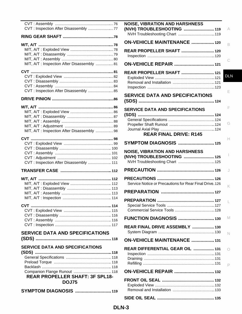
BASIC INSPECTIONDIAGNOSIS AND REPAIR WORKFLOW
Work Flow INFOID:0000000001278486
DETAILED FLOW
1.INTERVIEW FROM THE CUSTOMER
Clarify customer complaints before inspection. First of all, reproduce symptoms, and understand them fully.Ask customer about his/her complaints carefully. Check symptoms by driving vehicle with customer, if neces-sary.CAUTION:Customers are not professional. Never guess easily like “maybe the customer means that...,” or“maybe the customer mentions this symptom”.
>> GO TO 2.
2.CHECK 4WD WARNING LAMP
Start engine and drive at 30 km/h (19 MPH) or more for approx. 1 minute.Does 4WD warning lamp turn ON?YES >> GO TO 3.NO >> GO TO 6.
3.PERFORM SELF-DIAGNOSIS
With CONSULT-III1. Perform 4WD control unit self-diagnosis.2. Perform malfunction detected by self-diagnosis.3. Erase 4WD control unit self-diagnosis results.
>> GO TO 4.
4.CHECK TERMINALS AND HARNESS CONNECTORS
Check pin terminals for damage or loose connection with harness connector.
>> GO TO 5.
5.CHECK SYMPTOM REPRODUCTION
With CONSULT-IIIPerform DTC reproduction procedure for the error system.Is any error detected?YES >> GO TO 2.NO >> GO TO 6.
6.PERFORM SYMPTOM DIAGNOSIS
Perform the symptom diagnosis for each system.Is any malfunction present?YES >> GO TO 2.NO >> GO TO 7.
7.FINAL CHECK
With CONSULT-IIICheck input/output signal standard of 4WD control unit.Is the input/output the standard value?YES >> INSPECTION ENDNO >> GO TO 2.
DLN-5

[TRANSFER: TY30A]4WD SYSTEM
< FUNCTION DIAGNOSIS >
FUNCTION DIAGNOSIS4WD SYSTEM
System Diagram INFOID:0000000001278487
CONTROL DIAGRAM (WITHOUT ESP)
CONTROL DIAGRAM (WITH ESP)
JSDIA0275GB
DLN-6

4WD SYSTEM[TRANSFER: TY30A]
C
E
F
G
H
I
J
K
L
M
A
B
LN
N
O
P
< FUNCTION DIAGNOSIS >
D
CROSS-SECTIONAL VIEW (M/T, A/T)
JSDIA0276GB
JSDIA0206ZZ
DLN-7

[TRANSFER: TY30A]4WD SYSTEM
< FUNCTION DIAGNOSIS >
CROSS-SECTIONAL VIEW (CVT)
System Description INFOID:0000000001278488
DESCRIPTION• 4WD controls distribution of drive power between front-wheel drive (100:0) and 4WD (50:50) conditions
according to signals from sensors.• By receiving a steering angle sensor signal and G sensor signal, vehicle with ESP corrects a torque distribu-
tion for front and rear wheels according to a driving operation and a behavior of the vehicle during corneringand improves handle ability and safety on a slippery road surface.
• It transmits/receives each signal from the following 4WD control unit via CAN communication line. (WithoutESP)
1. Transfer case 2. Adapter case 3. Ring gear shaft
4. Ring gear 5. Companion flange 6. Drive pinion
1. Transfer case 2. Adapter case 3. Ring gear shaft
4. Ring gear 5. Companion flange 6. Drive pinion
JSDIA0205ZZ
Component parts Function
ABS actuator and electric unit (control unit)Transmits the following signals via CAN communication to 4WD control unit.• Vehicle speed signal• Stop lamp switch signal (brake signal)
ECMTransmits the following signals via CAN communication to 4WD control unit.• Accelerator pedal position signal• Engine speed signal
Combination meter
Transmits conditions of parking brake switch signal via CAN communication for 4WD con-trol unit.
Receives the following signals via CAN communication to 4WD control unit.• 4WD warning lamp signal• Mode lamp signal
DLN-8

4WD SYSTEM[TRANSFER: TY30A]
C
E
F
G
H
I
J
K
L
M
A
B
LN
N
O
P
< FUNCTION DIAGNOSIS >
D
• It transmits/receives each signal from the following ABS actuator and electric unit (control unit) control unitvia CAN communication line. (With ESP)
• It transmits/receives each signal from the following 4WD control unit via 4WD communication line. (WithESP)
AUTO Mode• Electronic control allows optimal distribution of torque to front/rear wheels to match road conditions.• 4WD mode makes possible stable driving, with no wheel spin, on snowy roads or other slippery surfaces.• On roads which do not require 4WD, AUTO mode contributes to improved fuel economy by driving in condi-
tions close to front-wheel drive.• Sensor inputs determine the vehicle's turning condition, and tight cornering/braking are controlled by distrib-
uting optimum torque to rear wheels.
LOCK Mode• Front/rear wheel torque distribution is fixed, ensuring stable driving when climbing slopes.• Vehicle will switch automatically to AUTO mode if vehicle speed increases. If vehicle speed then decreases,
the vehicle automatically returns to direct 4-wheel driving conditions.• LOCK mode will change to AUTO mode automatically, when the vehicle speed exceeds approx. 10 km/h (6
MPH). The LOCK indicator light keeps illuminating.NOTE:If there is a significant difference in pressure or wear between tires, full vehicle performance is not available.LOCK mode may be prohibited, or speeds at which LOCK mode is enabled may be restricted detecting tireconditions.
2WD ModeVehicle is in front-wheel drive.NOTE:• If front wheels are slipping in 2WD mode, do not switch to AUTO or LOCK. This can cause difficulties for the
system.• Even if the 4WD mode switch is in 2WD mode, the 4WD control unit occasionally automatically change to
AUTO mode depending on the driving condition (For example; Depressing the acceleration firmly). This isnot malfunction. However, 4WD indicator lamp dose not illuminate.
POWER TRANSFER DIAGRAM
Component parts Function
ECM
Transmits the following signals via CAN communication to ABS actuator and electric unit (control unit).• Accelerator pedal position signal• Engine speed signal
Combination meter
Transmits conditions of parking brake switch signal via CAN communication for ABS ac-tuator and electric unit (control unit).
Receives the following signals via CAN communication to ABS actuator and electric unit (control unit).• 4WD warning lamp signal• Mode lamp signal• Steering angle sensor signal• G sensor signal
Component parts Function
ABS actuator and electric unit (control unit)
Transmits conditions of 4WD solenoid signal via 4WD communication for 4WD control unit.
Receives the following signals via 4WD communication from 4WD control unit.• 4WD mode switch signal• 4WD solenoid monitor signal
DLN-9

[TRANSFER: TY30A]4WD SYSTEM
< FUNCTION DIAGNOSIS >
OPERATION PRINCIPLE
Electric Controlled Coupling
1. The 4WD control unit supplies command current to electric con-trolled coupling (4WD solenoid).
2. The control clutch is engaged by electromagnet and torque isdetected in control clutch.
3. The cam operates in response to control clutch torque andapplies pressure to main clutch.
4. The main clutch transmits torque to front wheels according topressing power.
• Transmission torque to the rear wheels is determined accord-ing to command current.
Component Parts Location INFOID:0000000001278489
LHD MODELS
1. Engine 2. Transaxle 3. Transfer
4. Propeller shaft 5. Electric controlled coupling 6. Rear final drive
JSDIA0208ZZ
SFIA0284E
SDIA1844E
DLN-10

4WD SYSTEM[TRANSFER: TY30A]
C
E
F
G
H
I
J
K
L
M
A
B
LN
N
O
P
< FUNCTION DIAGNOSIS >
D
RHD MODELS
1. 4WD indicator lamp 2. LOCK indicator lamp 3. 4WD warning lamp
4. 4WD mode switch 5. 4WD control unit 6. 4WD solenoid (in rear final drive)
A. Combination meter B. Console finisher assembly C. Glove box cover assembly removed
D. Rear final drive assembly
JSDIA0269ZZ
JSDIA0270ZZ
DLN-11

[TRANSFER: TY30A]4WD SYSTEM
< FUNCTION DIAGNOSIS >
Component Description INFOID:0000000001278490
*: With ESP
1. 4WD indicator lamp 2. LOCK indicator lamp 3. 4WD warning lamp
4. 4WD mode switch 5. 4WD control unit 6. 4WD solenoid (in rear final drive)
A. Combination meter B. Console finisher assembly C. Glove box cover assembly removed
D. Rear final drive assembly
Component parts Reference/Function
4WD control unit DLN-16, "Description"
Wheel sensors BRC-20, "Description"
4WD solenoid DLN-18, "Description"
Electric controlled coupling Transmits driving force to rear final drive.
4WD warning lamp DLN-34, "Description"
4WD indicator lamp DLN-36, "Description"
LOCK indicator lamp DLN-37, "Description"
4WD mode switch DLN-22, "Description"
ABS actuator and electric unit (control unit) DLN-17, "Description"
ECM DLN-25, "Description"
Combination meter DLN-36, "Description"
Steering angle sensor* BRC-141, "Description"
Yaw rate/side G sensor* BRC-143, "Description"
DLN-12

DIAGNOSIS SYSTEM (4WD CONTROL UNIT)[TRANSFER: TY30A]
C
E
F
G
H
I
J
K
L
M
A
B
LN
N
O
P
< FUNCTION DIAGNOSIS >
D
DIAGNOSIS SYSTEM (4WD CONTROL UNIT)
CONSULT-III Function (ALL MODE AWD/4WD) INFOID:0000000001278491
FUNCTIONCONSULT-III can display each diagnostic item using the diagnostic test modes shown following.
SELF-DIAG RESULT MODEDrive at 30 km/h or more for approximately 1 minute before performing the self-diagnosis.
Display Item List
Diagnostic test mode Function
ECU part number 4WD control unit part number can be read.
Self-diagnostic results Self-diagnostic results can be read and erased quickly.
Data monitor Input/Output data in the 4WD control unit can be read.
Active testDiagnostic Test Mode in which CONSULT-III drives some actuators apart from the 4WD control unit and also shifts some parameters in a specified range.
DTCItems
(CONSULT-III screen terms)Diagnostic item is detected when... Possible cause
C1201 CONTROLLER FAILURE Malfunction has occurred inside 4WD control unit.Internal malfunction of 4WD control unit
C1203 ABS SYSTEMMalfunction related to wheel sensor has been de-tected by ABS actuator and electric unit (control unit).
ABS malfunction• Vehicle speed signal error• Stop lamp switch signal
(brake signal) error
C1204 4WD SOLENOIDMalfunction related to 4WD solenoid has been de-tected.
Internal malfunction of elec-tronic controlled coupling
C1205 4WD ACTUATOR RLYMalfunction has been detected from 4WD actuator relay integrated with 4WD control unit, or malfunc-tion related to 4WD solenoid has been detected.
Internal malfunction of 4WD control unit
C1209 MODE SWMore than two switch inputs are simultaneously detected due to short circuit of 4WD mode switch.
Malfunction of 4WD mode switch or 4WD mode switch circuit.
C1210 ENGINE SIGNAL 1 Malfunction has been detected from ECM.
Malfunction of engine control system• Accelerator pedal position
signal error• Engine speed signal error
C1211 4WD COMM CIRCUIT4WD control unit cannot transmit signals to ABS actuator and electric unit (control unit).
• Open of the harness of 4WD communication line
• 4WD communication error- Transmission by 4WD con-
trol unit- Reception by ABS actuator
and electric unit (control unit)
C1212 4WD COMM CIRCUIT4WD control unit cannot receive signals from ABS actuator and electric unit (control unit).
• Short of harness of 4WD communication line on the power supply side or on the ground side.
• 4WD communication error- Reception by 4WD control
unit- Transmission by ABS actu-
ator and electric unit (con-trol unit)
DLN-13

[TRANSFER: TY30A]DIAGNOSIS SYSTEM (4WD CONTROL UNIT)
< FUNCTION DIAGNOSIS >
How to Erase Self-Diagnostic ResultsBefore erasing DTC memory, start the engine and drive at 30 km/h or more for approximately 1 minute. Checkthat ABS warning lamp turns OFF.NOTE:Make sure that ABS warning lamp turns OFF by driving for a minute at vehicle speed of 30 km/h (19 MPH) ormore after turning ignition switch OFF if 4WD warning lamp turns ON with system malfunction of “ABS SYS-TEM [C1203]”. 4WD warning lamp may not turn OFF if it is normal unless ignition switch turns OFF at onceand engine restarts after that.
DATA MONITOR MODE
Display Item List
×: Applicable : Optional item
ACTIVE TEST MODE
DescriptionUse this mode to determine and identify the details of a malfunction based on self-diagnostic results or datamonitor. 4WD control unit gives drive signal to actuator with receiving command from CONSULT-III to checkoperation of actuator.
Test Item
U1000 CAN COMM CIRCUITWhen 4WD control unit is not transmitting or re-ceiving CAN communication signal for 2 seconds or more.
• CAN communication error• Malfunction of 4WD control
unit
U1010 CONTROL UNIT (CAN)When detecting error during the initial diagnosis of CAN controller of 4WD control unit.
Malfunction of 4WD control unit
DTCItems
(CONSULT-III screen terms)Diagnostic item is detected when... Possible cause
Monitor item (Unit)
Monitor Menu
RemarksECU INPUT SIGNALS
MAINSIGNALS
FR RH SENSOR [km/h] or [mph] × × Wheel speed calculated by front wheel sensor RH sig-nal is displayed.
FR LH SENSOR [km/h] or [mph] × × Wheel speed calculated by front wheel sensor LH sig-nal is displayed.
RR RH SENSOR [km/h] or [mph] × × Wheel speed calculated by rear wheel sensor RH sig-nal is displayed.
RR LH SENSOR [km/h] or [mph] × × Wheel speed calculated by rear wheel sensor LH sig-nal is displayed.
BATTERY VOLT [V] Power supply voltage for 4WD control unit
THRTL POS SEN [%] Throttle opening status is displayed.
ETS SOLENOID [A] Monitored value of current at 4WD solenoid
STOP LAMP SW [On/Off]Stop lamp switch signal status via CAN communication line is displayed.
ENG SPEED SIG [Run/Stop] Engine status is displayed.
ETS ACTUATOR [On/Off]Operating condition of 4WD actuator relay (integrated in 4WD control unit) is displayed.
4WD WARN LAMP [On/Off] Control status of 4WD warning lamp is displayed.
4WD MODE SW [2WD/AUTO/LOCK] Mode switch is not equipped, but displayed.
4WD MODE MON [2WD/AUTO/LOCK] Control status of 4WD is displayed.
DIS-TIRE MONI [mm] Improper size tire installed condition is displayed.
P BRAKE SW [On/Off]Parking switch signal status via CAN communication line is displayed.
DLN-14

DIAGNOSIS SYSTEM (4WD CONTROL UNIT)[TRANSFER: TY30A]
C
E
F
G
H
I
J
K
L
M
A
B
LN
N
O
P
< FUNCTION DIAGNOSIS >
D
CAUTION:
Never energize continuously for a long time.
Test item Condition Description
ETS S/V(Detects 4WD solenoid)
• Vehicle stopped• Engine running• No DTC detected
Change command current value to 4WD solenoid, and then change driving mode. (Monitor value is normal if it is within approximately ±10% of command value.)• Qu: Increase current value in increments of 0.1 A• Qd: Decrease current value in increments of 0.1 A• UP: Increase current value in increments of 0.02 A• DOWN: Decrease current value in increments of 0.02 A
DLN-15

[TRANSFER: TY30A]C1201 4WD CONTROL UNIT
< COMPONENT DIAGNOSIS >
COMPONENT DIAGNOSISC1201 4WD CONTROL UNIT
Description INFOID:0000000001278492
• Controls driving force distribution by signals from each sensor from front wheel driving mode (100:0) to 4WDmode (50:50).
• 2WD mode is available by fail-safe function if malfunction is detected in 4WD system.
DTC Logic INFOID:0000000001278493
DTC DETECTION LOGIC
DTC CONFIRMATION PROCEDURE
1.DTC REPRODUCTION PROCEDURE
With CONSULT-III1. Turn the ignition switch OFF to ON.2. Perform 4WD control unit self-diagnosis.Is DTC “C1201” detected?YES >> Proceed to diagnosis procedure. Refer to DLN-16, "Diagnosis Procedure".NO >> INSPECTION END
Diagnosis Procedure INFOID:0000000001278494
1.PERFORM SELF-DIAGNOSIS
With CONSULT-III1. Erase 4WD control unit self-diagnosis results.2. Turn ignition switch OFF, and then wait 10 seconds or more.3. Perform 4WD control unit self-diagnosis.Is DTC “C1201” detected?YES >> Replace 4WD control unit. Refer to DLN-66, "LHD : Exploded View" (LHD models), DLN-67,
"RHD : Exploded View" (RHD models).NO >> Check 4WD control unit pin terminals for damage or loose connection with harness connector. If
any items are damaged, repair or replace damaged parts.
DTCItems
(CONSULT-III screen terms)Diagnostic item is detected when... Possible cause
C1201 CONTROLLER FAILUREMalfunction has occurred inside 4WD control unit.
Internal malfunction of 4WD control unit
DLN-16

C1203 ABS ACTUATOR AND ELECTRIC UNIT (CONTROL UNIT)[TRANSFER: TY30A]
C
E
F
G
H
I
J
K
L
M
A
B
LN
N
O
P
< COMPONENT DIAGNOSIS >
D
C1203 ABS ACTUATOR AND ELECTRIC UNIT (CONTROL UNIT)
Description INFOID:0000000001278495
Transmits the following signals via CAN communication to 4WD control unit.• Vehicle speed signal• Stop lamp switch signal (brake signal)
DTC Logic INFOID:0000000001278496
DTC DETECTION LOGIC
DTC CONFIRMATION PROCEDURE
1.DTC REPRODUCTION PROCEDURE
With CONSULT-III1. Start engine and drive at 30 km/h (19 MPH) or more for approx. 1 minute.2. Perform 4WD control unit self-diagnosis.Is DTC “C1203” detected?YES >> Proceed to diagnosis procedure. Refer to DLN-17, "Diagnosis Procedure".NO >> INSPECTION END
Diagnosis Procedure INFOID:0000000001278497
1.PERFORM ABS ACTUATOR AND ELECTRIC UNIT (CONTROL UNIT) SELF-DIAGNOSIS
With CONSULT-IIIPerform ABS actuator and electric unit (control unit) self-diagnosis.Is any error system detected?YES >> Check the error system.NO >> GO TO 2.
2.PERFORM SELF-DIAGNOSIS
With CONSULT-III1. Erase 4WD control unit self-diagnosis results.2. Start engine and drive vehicle at 30 km/h (19 MPH) for at least 1 minute.3. Make sure that ABS warning lamp turns OFF.4. Perform 4WD control unit self-diagnosis.Is DTC “C1203” detected?YES >> Replace 4WD control unit. Refer to DLN-66, "LHD : Exploded View" (LHD models), DLN-67,
"RHD : Exploded View" (RHD models).NO >> Check 4WD control unit pin terminals for damage or loose connection with harness connector. If
any items are damaged, repair or replace damaged parts.
DTCItems
(CONSULT-III screen terms)Diagnostic item is detected when... Possible cause
C1203 ABS SYSTEMMalfunction related to wheel sensor has been detected by ABS actuator and electric unit (control unit).
ABS malfunction• Vehicle speed signal error• Stop lamp switch signal (brake signal)
error
DLN-17

[TRANSFER: TY30A]C1204 4WD SOLENOID
< COMPONENT DIAGNOSIS >
C1204 4WD SOLENOID
Description INFOID:0000000001278498
Controls electric controlled coupling by command current from 4WD control unit.
DTC Logic INFOID:0000000001278499
DTC DETECTION LOGIC
DTC CONFIRMATION PROCEDURE
1.DTC REPRODUCTION PROCEDURE
With CONSULT-III1. Turn the ignition switch OFF to ON.2. Perform 4WD control unit self-diagnosis.Is DTC “C1204” detected?YES >> Proceed to diagnosis procedure. Refer to DLN-18, "Diagnosis Procedure".NO >> INSPECTION END
Diagnosis Procedure INFOID:0000000001278500
1.CHECK 4WD SOLENOID POWER SUPPLY
1. Turn the ignition switch OFF.2. Disconnect 4WD control unit harness connector.3. Turn the ignition switch ON.
CAUTION:Never start the engine.
4. Check the voltage between 4WD control unit harness connector and ground.
Is the inspection result normal?YES >> GO TO 2.NO >> Check the following. If any items are damaged, repair or replace damaged parts.
• 10A fuse (#12) open- Short among 10A fuse (#12) connector, 4WD control unit harness connector No. 9 terminal and
the ground- Open between the battery and 4WD control unit harness connector No. 9 terminal
2.CHECK 4WD SOLENOID GROUND
1. Turn the ignition switch OFF.2. Check the continuity between 4WD control unit harness connector and ground.
Is the inspection result normal?YES >> GO TO 3.
DTCItems
(CONSULT-III screen terms)Diagnostic item is detected when... Possible cause
C1204 4WD SOLENOIDMalfunction related to 4WD solenoid has been detected.
Internal malfunction of electronic con-trolled coupling
4WD control unitGround Voltage (Approx.)
Connector Terminal
M69 9 Ground Battery voltage
4WD control unitGround Continuity
Connector Terminal
M6910
Ground Existed11
DLN-18

C1204 4WD SOLENOID[TRANSFER: TY30A]
C
E
F
G
H
I
J
K
L
M
A
B
LN
N
O
P
< COMPONENT DIAGNOSIS >
D
NO >> Repair or replace damaged parts.
3.CHECK 4WD SOLENOID CIRCUIT (1)
Check the resistance between 4WD control unit harness connector terminals.
Is the inspection result normal? YES >> GO TO 5. NO >> GO TO 4.
4.CHECK 4WD SOLENOID CIRCUIT (2)
1. Disconnect 4WD solenoid harness connector.2. Check the continuity between 4WD control unit harness connector and 4WD solenoid harness connector.
3. Check the continuity between 4WD control unit harness connector and the ground.
4. Check the continuity between 4WD solenoid harness connector and the ground.
Is the inspection result normal?YES >> GO TO 5.NO >> Repair or replace damaged parts.
5.CHECK 4WD SOLENOID
Check the resistance between 4WD solenoid harness connector terminals.
Is the inspection result normal?YES >> GO TO 6.NO >> 4WD solenoid is malfunctioning. Replace electric controlled coupling. Refer to DLN-136,
"Exploded View".
6.CHECK TERMINALS AND HARNESS CONNECTORS
1. Check 4WD control unit pin terminals for damage or loose connection with harness connector.2. Check 4WD solenoid pin terminals for damage or loose connection with harness connector.Is the inspection result normal?
4WD control unit Resistance (Approx.)
Connector Terminal
M69 1 2 2.45 Ω
4WD control unit 4WD solenoidContinuity
Connector Terminal Connector Terminal
M691
B2511
Existed2 2
4WD control unitGround Continuity
Connector Terminal
M691
Ground Not existed2
4WD solenoidGround Continuity
Connector Terminal
B2511
Ground Not existed2
4WD solenoid Resistance (Approx.)
Connector Terminal
B251 1 2 2.45 Ω
DLN-19

[TRANSFER: TY30A]C1204 4WD SOLENOID
< COMPONENT DIAGNOSIS >YES >> Replace 4WD control unit. Refer to DLN-66, "LHD : Exploded View" (LHD models), DLN-67,
"RHD : Exploded View" (RHD models).NO >> Repair or replace damaged parts.
Component Inspection INFOID:0000000001278501
1.CHECK 4WD SOLENOID
1. Turn the ignition switch OFF.2. Disconnect 4WD solenoid harness connector.3. Check the resistance between 4WD solenoid harness connector terminals.
Is the inspection result normal?YES >> INSPECTION ENDNO >> 4WD solenoid is malfunctioning. Replace electric controlled coupling. Refer to DLN-136,
"Exploded View".
4WD solenoid Resistance (Approx.)
Connector Terminal
B251 1 2 2.45 Ω
DLN-20

C1205 4WD ACTUATOR RELAY[TRANSFER: TY30A]
C
E
F
G
H
I
J
K
L
M
A
B
LN
N
O
P
< COMPONENT DIAGNOSIS >
D
C1205 4WD ACTUATOR RELAY
Description INFOID:0000000001278502
4WD solenoid is supplied with voltage by the internal circuit of 4WD control unit.
DTC Logic INFOID:0000000001278503
DTC DETECTION LOGIC
DTC CONFIRMATION PROCEDURE
1.DTC REPRODUCTION PROCEDURE
With CONSULT-III1. Turn the ignition switch OFF to ON.2. Perform 4WD control unit self-diagnosis.Is DTC “C1205” detected?YES >> Proceed to diagnosis procedure. Refer to DLN-21, "Diagnosis Procedure".NO >> INSPECTION END
Diagnosis Procedure INFOID:0000000001278504
1.PERFORM SELF-DIAGNOSIS
With CONSULT-III1. Erase 4WD control unit self-diagnosis results.2. Turn ignition switch OFF, and wait 10 seconds or more.3. Perform 4WD control unit self-diagnosis.Is DTC “C1205” detected?YES >> Replace 4WD control unit. Refer to DLN-66, "LHD : Exploded View" (LHD models), DLN-67,
"RHD : Exploded View" (RHD models).NO >> Check 4WD control unit pin terminals for damage or loose connection with harness connector. If
any items are damaged, repair or replace damaged parts.
DTCItems
(CONSULT-III screen terms)Diagnostic item is detected when... Possible cause
C1205 4WD ACTUATOR RLY
Malfunction has been detected from 4WD actuator relay integrated with 4WD control unit, or malfunction related to 4WD solenoid has been detected.
Internal malfunction of 4WD control unit
DLN-21

[TRANSFER: TY30A]C1209 MODE SW
< COMPONENT DIAGNOSIS >
C1209 MODE SW
Description INFOID:0000000001278505
Able to select 2WD, AUTO or LOCK mode.
DTC Logic INFOID:0000000001278506
DTC DETECTION LOGIC
DTC CONFIRMATION PROCEDURE
1.DTC REPRODUCTION PROCEDURE
With CONSULT-III1. Turn the ignition switch OFF to ON.2. Perform 4WD control unit self-diagnosis.Is DTC “C1209” detected?YES >> Proceed to diagnosis procedure. Refer to DLN-22, "Diagnosis Procedure".NO >> INSPECTION END
Diagnosis Procedure INFOID:0000000001278507
1.CHECK 4WD MODE SWITCH
1. Turn the ignition switch OFF.2. Remove 4WD mode switch.3. Check the continuity between 4WD mode switch connector terminals.
Is the inspection result normal?YES >> GO TO 2.NO >> Replace 4WD mode switch.
2.CHECK 4WD MODE SWITCH CIRCUIT (1)
Check the continuity between 4WD mode switch harness connector and ground.
DTCItems
(CONSULT-III screen terms)Diagnostic item is detected when... Possible cause
C1209 MODE SWMore than two switch inputs are simulta-neously detected due to short circuit of 4WD mode switch.
Malfunction of 4WD mode switch or 4WD mode switch circuit.
4WD mode switchContinuity
Connector Terminal Condition
M8
2 34WD mode switch: 2WD Existed
Except the above Not existed
2 6
4WD mode switch: 2WD Not existed
4WD mode switch: AUTO
Existed4WD mode switch: LOCK(State of hold of LOCK position)
2 8
4WD mode switch: LOCK(State of hold of LOCK position)
Existed
Except the above Not existed
4WD mode switchGround Continuity
Connector Terminal
M8 2 Ground Existed
DLN-22

C1209 MODE SW[TRANSFER: TY30A]
C
E
F
G
H
I
J
K
L
M
A
B
LN
N
O
P
< COMPONENT DIAGNOSIS >
D
Is the inspection result normal?YES >> GO TO 3.NO >> Repair or replace damaged parts.
3.CHECK 4WD MODE SWITCH CIRCUIT (2)
1. Disconnect 4WD control unit harness connector.2. Check the continuity between 4WD control unit harness connector and 4WD mode switch harness con-
nector.
3. Check the continuity between 4WD control unit harness connector and ground.
Is the inspection result normal?YES >> GO TO 4.NO >> Repair or replace damaged parts.
4.CHECK 4WD CONTROL UNIT OUTPUT SIGNAL
1. Connect 4WD control unit harness connector.2. Turn the ignition switch ON.3. Check the voltage between 4WD mode switch harness connector and ground.
Is the inspection result normal?YES >> Check each harness connector pin terminal for disconnection.NO >> Replace 4WD control unit. Refer to DLN-66, "LHD : Exploded View" (LHD models), DLN-67,
"RHD : Exploded View" (RHD models).
Component Inspection INFOID:0000000001278508
1.CHECK 4WD MODE SWITCH
1. Turn the ignition switch OFF.2. Remove 4WD mode switch.
4WD control unit 4WD mode switchContinuity
Connector Terminal Connector Terminal
M69
14
M8
3 Not existed
14 6 Not existed
14 8 Existed
5 3 Not existed
5 6 Existed
5 8 Not existed
12 3 Existed
12 6 Not existed
12 8 Not existed
4WD control unitGround Continuity
Connector Terminal
M69
14
Ground Not existed5
12
4WD mode switchGround Voltage (Approx.)
Connector Terminal
M8
3
Ground Battery voltage6
8
DLN-23

[TRANSFER: TY30A]C1209 MODE SW
< COMPONENT DIAGNOSIS >3. Check the continuity between 4WD mode switch connector terminals.
Is the inspection result normal?YES >> INSPECTION ENDNO >> Replace 4WD mode switch.
4WD mode switchContinuity
Connector Terminal Condition
M8
2 34WD mode switch: 2WD Existed
Except the above Not existed
2 6
4WD mode switch: 2WD Not existed
4WD mode switch: AUTO
Existed4WD mode switch: LOCK(State of hold of LOCK position)
2 8
4WD mode switch: LOCK(State of hold of LOCK position)
Existed
Except the above Not existed
DLN-24

C1210 ECM[TRANSFER: TY30A]
C
E
F
G
H
I
J
K
L
M
A
B
LN
N
O
P
< COMPONENT DIAGNOSIS >
D
C1210 ECM
Description INFOID:0000000001278509
Transmits the following signals via CAN communication to 4WD control unit.• Accelerator pedal position signal• Engine speed signal
DTC Logic INFOID:0000000001278510
DTC DETECTION LOGIC
DTC CONFIRMATION PROCEDURE
1.DTC REPRODUCTION PROCEDURE
With CONSULT-III1. Start the engine. Drive the vehicle for a while.2. Perform 4WD control unit self-diagnosis.Is DTC “C1210” detected?YES >> Proceed to diagnosis procedure. Refer to DLN-25, "Diagnosis Procedure".NO >> INSPECTION END
Diagnosis Procedure INFOID:0000000001278511
1.PERFORM ECM SELF-DIAGNOSIS
With CONSULT-IIIPerform ECM self-diagnosis.Is any error system detected?YES >> Check the error system.NO >> GO TO 2.
2.PERFORM SELF-DIAGNOSIS
With CONSULT-III1. Erase 4WD control unit self-diagnosis results.2. Turn the ignition switch OFF.3. Start the engine. Drive the vehicle for a while.4. Make sure that malfunction indicator (MI) turns OFF.5. Stop the vehicle. Perform 4WD control unit self-diagnosis.Is DTC “C1210” detected?YES >> Replace 4WD control unit. Refer to DLN-66, "LHD : Exploded View" (LHD models), DLN-67,
"RHD : Exploded View" (RHD models).NO >> Check 4WD control unit pin terminals for damage or loose connection with harness connector. If
any items are damaged, repair or replace damaged parts.
DTCItems
(CONSULT-III screen terms)Diagnostic item is detected when... Possible cause
C1210 ENGINE SIGNAL 1Malfunction has been detected from ECM.
Malfunction of engine control system• Accelerator pedal position signal error• Engine speed signal error
DLN-25

[TRANSFER: TY30A]C1211 4WD COMMUNICATION
< COMPONENT DIAGNOSIS >
C1211 4WD COMMUNICATION
Description INFOID:0000000001307639
• 4WD communication transmits and receives signals between control units (ABS control unit to 4WD controlunit) connected with a dedicated line (single line).
• Transmits conditions of 4WD solenoid signall via 4WD communication for 4WD control unit.• Receives the following signals via 4WD communication from 4WD control unit.- 4WD mode switch signal- 4WD solenoid monitor signal
DTC Logic INFOID:0000000001307640
DTC DETECTION LOGIC
DTC CONFIRMATION PROCEDURE
1.DTC REPRODUCTION PROCEDURE
With CONSULT-III1. Turn the ignition switch OFF to ON.2. Perform 4WD control unit self-diagnosis.Is DTC “C1211” detected?YES >> Proceed to diagnosis procedure. Refer to DLN-26, "Diagnosis Procedure".NO >> INSPECTION END
Diagnosis Procedure INFOID:0000000001307641
1.CHECK 4WD COMMUNICATION LINE
1. Turn the ignition switch OFF.2. Disconnect 4WD control unit harness connector and ABS actuator and electric unit (control unit).3. Check the continuity between 4WD control unit harness connector and ABS actuator and electric unit
(control unit).
Is the inspection result normal?YES >> GO TO 2.NO >> Repair or replace damaged parts.
2.CHECK TERMINALS AND HARNESS CONNECTORS
• Check 4WD control unit pin terminals for damage or loose connection with harness connector.• Check ABS actuator and electric unit (control unit) pin terminals for damage or loose connection with har-
ness connector.Is the inspection result normal?YES >> Replace 4WD control unit, and then GO TO 3. Refer to DLN-66, "LHD : Exploded View" (LHD
models), DLN-67, "RHD : Exploded View" (RHD models).NO >> Repair or replace damaged parts.
DTCItems
(CONSULT-III screen terms)Diagnostic item is detected when... Possible cause
C1211 4WD COMM CIRCUIT4WD control unit cannot transmit signals to ABS actuator and electric unit (control unit).
• Open of the harness of 4WD commu-nication line
• 4WD communication error- Transmission by 4WD control unit- Reception by ABS actuator and elec-
tric unit (control unit)
4WD control unitABS actuator and electric
unit (control unit) Continuity
Connector Terminal Connector Terminal
M69 6 E36 20 Existed
DLN-26

C1211 4WD COMMUNICATION[TRANSFER: TY30A]
C
E
F
G
H
I
J
K
L
M
A
B
LN
N
O
P
< COMPONENT DIAGNOSIS >
D
3.PERFORM SELF-DIAGNOSIS
With CONSULT-III1. Erase 4WD control unit self-diagnosis and ABS actuator and electric unit (control unit) results.2. Perform 4WD control unit self-diagnosis.Is DTC “C1211” detected?YES >> Replace ABS actuator and electric unit (control unit). Refer to BRC-201, "Exploded View".NO >> INSPECTION END
DLN-27

[TRANSFER: TY30A]C1212 4WD COMMUNICATION
< COMPONENT DIAGNOSIS >
C1212 4WD COMMUNICATION
Description INFOID:0000000001307664
• 4WD communication transmits and receives signals between control units (ABS control unit to 4WD controlunit) connected with a dedicated line (single line).
• Transmits conditions of 4WD solenoid signall via 4WD communication for 4WD control unit.• Receives the following signals via 4WD communication from 4WD control unit.- 4WD mode switch signal- 4WD solenoid monitor signal
DTC Logic INFOID:0000000001307637
DTC DETECTION LOGIC
DTC CONFIRMATION PROCEDURE
1.DTC REPRODUCTION PROCEDURE
With CONSULT-III1. Turn the ignition switch OFF to ON.2. Perform 4WD control unit self-diagnosis.Is DTC “C1212” detected?YES >> Proceed to diagnosis procedure. Refer to DLN-28, "Diagnosis Procedure".NO >> INSPECTION END
Diagnosis Procedure INFOID:0000000001307638
1.CHECK 4WD COMMUNICATION LINE (1)
1. Turn the ignition switch OFF.2. Disconnect 4WD control unit harness connector and ABS actuator and electric unit (control unit).3. Check the voltage between 4WD control unit harness connector and ground.
Is the inspection result normal?YES >> GO TO 2.NO >> Repair or replace damaged parts.
2.CHECK 4WD COMMUNICATION LINE (2)
Check the continuity between 4WD control unit harness connector and ground.
Is the inspection result normal?
DTCItems
(CONSULT-III screen terms)Diagnostic item is detected when... Possible cause
C1212 4WD COMM CIRCUIT4WD control unit cannot receive signals from ABS actuator and electric unit (con-trol unit).
• Short of harness of 4WD communica-tion line on the power supply side or on the ground side.
• 4WD communication error- Reception by 4WD control unit- Transmission by ABS actuator and
electric unit (control unit)
4WD control unitGround Voltage (Approx.)
Connector Terminal
M69 6 Ground 0 V
4WD control unitGround Continuity
Connector Terminal
M69 6 Ground Not existed
DLN-28

C1212 4WD COMMUNICATION[TRANSFER: TY30A]
C
E
F
G
H
I
J
K
L
M
A
B
LN
N
O
P
< COMPONENT DIAGNOSIS >
D
YES >> GO TO 3.NO >> Repair or replace damaged parts.
3.CHECK TERMINALS AND HARNESS CONNECTORS
• Check ABS actuator and electric unit (control unit) pin terminals for damage or loose connection with har-ness connector.
• Check 4WD control unit pin terminals for damage or loose connection with harness connector.Is the inspection result normal?YES >> Replace ABS actuator and electric unit (control unit), and then GO TO 4. Refer to BRC-201,
"Exploded View".NO >> Repair or replace damaged parts.
4.PERFORM SELF-DIAGNOSIS
With CONSULT-III1. Erase 4WD control unit self-diagnosis and ABS actuator and electric unit (control unit) results.2. Perform 4WD control unit self-diagnosis.Is DTC “C1212” detected?YES >> Replace 4WD control unit. Refer to DLN-66, "LHD : Exploded View" (LHD models), DLN-67,
"RHD : Exploded View" (RHD models).NO >> INSPECTION END
DLN-29

[TRANSFER: TY30A]U1000 CAN COMM CIRCUIT
< COMPONENT DIAGNOSIS >
U1000 CAN COMM CIRCUIT
Description INFOID:0000000001278512
CAN (Controller Area Network) is a serial communication line for real time application. It is an on-vehicle mul-tiplex communication line with high data communication speed and excellent error detection ability. Many elec-tronic control units are equipped onto a vehicle, and each control unit shares information and links with othercontrol units during operation (not independent). In CAN communication, control units are connected with 2communication lines (CAN-H line, CAN-L line) allowing a high rate of information transmission with less wiring.Each control unit transmits/receives data but selectively reads required data only. Refer to LAN-25, "CANCommunication Signal Chart".
DTC Logic INFOID:0000000001278513
DTC DETECTION LOGIC
DTC CONFIRMATION PROCEDURE
1.DTC REPRODUCTION PROCEDURE
With CONSULT-III1. Turn the ignition switch OFF to ON.2. Perform 4WD control unit self-diagnosis.Is DTC “U1000” detected?YES >> Proceed to diagnosis procedure. Refer to DLN-30, "Diagnosis Procedure".NO >> INSPECTION END
Diagnosis Procedure INFOID:0000000001278514
1.PERFORM SELF-DIAGNOSIS
With CONSULT-IIIPerform 4WD control unit self-diagnosis.Is DTC “U1000” detected?YES >> CAN specification chart. Refer to LAN-13, "Trouble Diagnosis Flow Chart".NO >> INSPECTION END
DTCItems
(CONSULT-III screen terms)Diagnostic item is detected when... Possible cause
U1000 CAN COMM CIRCUITWhen 4WD control unit is not transmit-ting or receiving CAN communication signal for 2 seconds or more.
• CAN communication error• Malfunction of 4WD control unit
DLN-30

U1010 CONTROL UNIT (CAN)[TRANSFER: TY30A]
C
E
F
G
H
I
J
K
L
M
A
B
LN
N
O
P
< COMPONENT DIAGNOSIS >
D
U1010 CONTROL UNIT (CAN)
Description INFOID:0000000001307635
CAN (Controller Area Network) is a serial communication line for real time application. It is an on-vehicle mul-tiplex communication line with high data communication speed and excellent error detection ability. Many elec-tronic control units are equipped onto a vehicle, and each control unit shares information and links with othercontrol units during operation (not independent). In CAN communication, control units are connected with 2communication lines (CAN-H line, CAN-L line) allowing a high rate of information transmission with less wiring.Each control unit transmits/receives data but selectively reads required data only. Refer to LAN-25, "CANCommunication Signal Chart".
DTC Logic INFOID:0000000001278516
DTC DETECTION LOGIC
DTC CONFIRMATION PROCEDURE
1.DTC REPRODUCTION PROCEDURE
With CONSULT-III1. Turn the ignition switch OFF to ON.2. Perform 4WD control unit self-diagnosis.Is DTC “U1010” detected?YES >> Proceed to diagnosis procedure. Refer to DLN-31, "Diagnosis Procedure".NO >> INSPECTION END
Diagnosis Procedure INFOID:0000000001278517
1.CHECK 4WD CONTROL UNIT
Check 4WD control unit harness connector for disconnection and deformation.Is the inspection result normal? YES >> Replace 4WD control unit. Refer to DLN-66, "LHD : Exploded View" (LHD models), DLN-67,
"RHD : Exploded View" (RHD models).NO >> Repair or replace damaged parts.
DTCItems
(CONSULT-III screen terms)Diagnostic item is detected when... Possible cause
U1010 CONTROL UNIT (CAN)When detecting error during the initial di-agnosis of CAN controller of 4WD con-trol unit.
Malfunction of 4WD control unit
DLN-31

[TRANSFER: TY30A]POWER SUPPLY AND GROUND CIRCUIT
< COMPONENT DIAGNOSIS >
POWER SUPPLY AND GROUND CIRCUIT
Description INFOID:0000000001278518
Supplies power to 4WD control unit.
Diagnosis Procedure INFOID:0000000001278519
1.CHECK 4WD CONTROL UNIT POWER SUPPLY
1. Turn the ignition switch OFF.2. Disconnect 4WD control unit harness connector.3. Check the voltage between 4WD control unit harness connector and ground.
4. Turn the ignition switch ON.CAUTION:Never start the engine.
5. Check the voltage between 4WD control unit harness connector and ground.
Is the inspection result normal?YES >> GO TO 2.NO >> Check the following. If any items are damaged, repair or replace damaged parts.
• 10A fuse (#59) open- Short among 10A fuse (#59) connector, 4WD control unit harness connector No. 7 terminal and
the ground- Open between the ignition switch and 4WD control unit harness connector No. 7 terminal• Ignition switch. Refer to SEC-64, "Diagnosis Procedure" (With Intelligent Key system), SEC-
268, "Diagnosis Procedure" (Without Intelligent Key system).
2.CHECK 4WD SOLENOID POWER SUPPLY
1. Turn the ignition switch OFF.2. Check the voltage between 4WD control unit harness connector and ground.
3. Turn the ignition switch ON.CAUTION:Never start the engine.
4. Check the voltage between 4WD control unit harness connector and ground.
Is the inspection result normal?YES >> GO TO 3.NO >> Check the following. If any items are damaged, repair or replace damaged parts.
• 10A fuse (#12) open
4WD control unitGround Voltage (Approx.)
Connector Terminal
M69 7 Ground 0 V
4WD control unitGround Voltage (Approx.)
Connector Terminal
M69 7 Ground Battery voltage
4WD control unitGround Voltage (Approx.)
Connector Terminal
M69 9 Ground Battery voltage
4WD control unitGround Voltage (Approx.)
Connector Terminal
M69 9 Ground Battery voltage
DLN-32

POWER SUPPLY AND GROUND CIRCUIT[TRANSFER: TY30A]
C
E
F
G
H
I
J
K
L
M
A
B
LN
N
O
P
< COMPONENT DIAGNOSIS >
D
- Short among 10A fuse (#12) connector, 4WD control unit harness connector No. 9 terminal andthe ground
- Open between the battery and 4WD control unit harness connector No. 9 terminal
3.CHECK 4WD SOLENOID VALVE GROUND
1. Turn the ignition switch OFF.2. Check the continuity between 4WD control unit harness connector and ground.
Is the inspection result normal?YES >> INSPECTION ENDNO >> Repair or replace damaged parts.
4WD control unitGround Continuity
Connector Terminal
M6910
Ground Existed11
DLN-33

[TRANSFER: TY30A]4WD WARNING LAMP
< COMPONENT DIAGNOSIS >
4WD WARNING LAMP
Description INFOID:0000000001278520
• Turns ON when there is a malfunction in 4WD system. It indicates that fail-safe mode is engaged and vehi-cle change to front-wheel drive or shifting driving force-4WD (Rear-wheels still have some driving torque).
• Also turns ON when ignition switch is turned ON, for purpose of lamp check. Turns OFF after the enginestarts if system is normal.
4WD WARNING LAMP INDICATION
CAUTION:• 4WD warning lamp also turns ON due to data reception error, CAN communication error etc.• 4WD warning lamp also turns ON due to data reception error, 4WD communication error. (With ESP)
Diagnosis Procedure INFOID:0000000001278521
1.CHECK POWER SUPPLY AND GROUND CIRCUIT
Perform the trouble diagnosis for power supply and ground circuit. Refer to DLN-32, "Diagnosis Procedure".Is the inspection result normal?YES >> GO TO 2. (With ESP) GO TO 3. (Without ESP)NO >> Repair or replace the malfunctioning part.
2.CHECK POWER SUPPLY AND GROUND CIRCUIT [ABS ACTUATOR AND ELECTRIC UNIT (CONTROLUNI]
Perform the trouble diagnosis for power supply and ground circuit. Refer to BRC-115, "Diagnosis Procedure".Is the inspection result normal?YES >> GO TO 3.NO >> Repair or replace the malfunctioning part.
3.PERFORM SELF-DIAGNOSIS
With CONSULT-IIIPerform 4WD control unit self-diagnosis.Is DTC “U1000” detected?YES >> CAN specification chart. Refer to LAN-13, "Trouble Diagnosis Flow Chart".NO >> GO TO 4.
4.CHECK 4WD WARNING LAMP SIGNAL
With CONSULT-III1. Turn the ignition switch ON.
CAUTION:Never start the engine.
2. Check “4WD WARN LAMP” of 4WD control unit CONSULT-III “DATA MONITOR”.Does the item on “DATA MONITOR” indicate “On”?YES >> GO TO 5.NO-1 >> Without ESP: Replace 4WD control unit. Refer to DLN-66, "LHD : Exploded View" (LHD models),
DLN-67, "RHD : Exploded View" (RHD models).
Condition 4WD warning lamp
Lamp checkTurns ON when ignition switch is turned ON. Turns OFF after
engine start.
4WD system malfunction ON
Protection function is activated due to heavy load to electric controlled coupling. (4WD system is not malfunctioning and 4WD system chang-es to 2WD mode.)
Quick blinking: 2 times/second (Blinking in approx. 1 minute and then turning OFF)
Large difference in diameter of front/rear tiresSlow blinking: 1 time/2 seconds
(Continuing to blink until turning ignition switch OFF)
Other than above (system normal) OFF
DLN-34

4WD WARNING LAMP[TRANSFER: TY30A]
C
E
F
G
H
I
J
K
L
M
A
B
LN
N
O
P
< COMPONENT DIAGNOSIS >
D
NO-2 >> With ESP: Replace ABS actuator and electric unit (control unit). Refer to BRC-201, "ExplodedView".
5.CHECK COMBINATION METER POWER SUPPLY CIRCUIT
Perform the trouble diagnosis for combination meter power supply circuit. Refer to MWI-35, "COMBINATIONMETER : Diagnosis Procedure".Is the inspection result normal?YES >> INSPECTION ENDNO >> Repair or replace the malfunctioning part.
DLN-35

[TRANSFER: TY30A]4WD INDICATOR LAMP
< COMPONENT DIAGNOSIS >
4WD INDICATOR LAMP
Description INFOID:0000000001278522
The following is the indications of indicator lamp after engine start.
4WD INDICATOR LAMP AND LOCK INDICATOR LAMP
Diagnosis Procedure INFOID:0000000001278523
1.CHECK 4WD WARNING LAMP
Start engine and drive at 30 km/h (19 MPH) or more for approx. 1 minute.Does 4WD warning lamp turn ON?YES >> Go to DLN-34, "Diagnosis Procedure".NO >> GO TO 2.
2.CHECK 4WD MODE SWITCH
Perform the trouble diagnosis for 4WD mode switch. Refer to DLN-22, "Diagnosis Procedure".Is the inspection result normal?YES >> GO TO 3.NO >> Repair or replace the malfunctioning part.
3.CHECK 4WD INDICATOR LAMP SIGNAL
With CONSULT-III1. Start the engine.
CAUTION:Stop the vehicle.
2. Change 4WD mode switch in “AUTO” from “2WD”.3. Check “4WD MODE MON” of 4WD control unit CONSULT-III “DATA MONITOR”.Does the item on “DATA MONITOR” indicate “AUTO”?YES >> GO TO 4.NO >> Replace 4WD control unit. Refer to DLN-66, "LHD : Exploded View" (LHD models), DLN-67,
"RHD : Exploded View" (RHD models).
4.CHECK COMBINATION METER POWER SUPPLY CIRCUIT
Perform the trouble diagnosis for combination meter power supply circuit. Refer to MWI-35, "COMBINATIONMETER : Diagnosis Procedure".Is the inspection result normal?YES >> INSPECTION ENDNO >> Repair or replace the malfunctioning part.
Condition 4WD indicator lamp LOCK indicator lamp
2WD mode OFF OFF
AUTO mode ON OFF
LOCK mode ON ON
DLN-36

LOCK INDICATOR LAMP[TRANSFER: TY30A]
C
E
F
G
H
I
J
K
L
M
A
B
LN
N
O
P
< COMPONENT DIAGNOSIS >
D
LOCK INDICATOR LAMP
Description INFOID:0000000001308696
The following is the indications of indicator lamp after engine start.
4WD INDICATOR LAMP AND LOCK INDICATOR LAMP
Diagnosis Procedure INFOID:0000000001308697
1.CHECK 4WD WARNING LAMP
Start engine and drive at 30 km/h (19 MPH) or more for approx. 1 minute.Does 4WD warning lamp turn ON?YES >> Go to DLN-34, "Diagnosis Procedure".NO >> GO TO 2.
2.CHECK 4WD MODE SWITCH
Perform the trouble diagnosis for 4WD mode switch. Refer to DLN-22, "Diagnosis Procedure".Is the inspection result normal?YES >> GO TO 3.NO >> Repair or replace the malfunctioning part.
3.CHECK LOCK INDICATOR LAMP SIGNAL
With CONSULT-III1. Start the engine.
CAUTION:Stop the vehicle.
2. Change 4WD mode switch in “LOCK” from “AUTO”.3. Check “4WD MODE MON” of 4WD control unit CONSULT-III “DATA MONITOR”.Does the item on “DATA MONITOR” indicate “LOCK”?YES >> GO TO 4.NO >> Replace 4WD control unit. Refer to DLN-66, "LHD : Exploded View" (LHD models), DLN-67,
"RHD : Exploded View" (RHD models).
4.CHECK COMBINATION METER POWER SUPPLY CIRCUIT
Perform the trouble diagnosis for combination meter power supply circuit. Refer to MWI-35, "COMBINATIONMETER : Diagnosis Procedure".Is the inspection result normal?YES >> INSPECTION ENDNO >> Repair or replace the malfunctioning part.
Condition 4WD indicator lamp LOCK indicator lamp
2WD mode OFF OFF
AUTO mode ON OFF
LOCK mode ON ON
DLN-37

[TRANSFER: TY30A]4WD CONTROL UNIT
< ECU DIAGNOSIS >
ECU DIAGNOSIS4WD CONTROL UNIT
Reference Value INFOID:0000000001278526
VALUES ON THE DIAGNOSIS TOOL
Monitor item Condition Value/Status
FR RH SENSOR
Vehicle stopped 0.00 km/h (0.00 mph)
Vehicle runningCAUTION:Check air pressure of tire under standard condition.
Approximately equal to the indi-cation on speedometer (Inside of ±10%)
FR LH SENSOR
Vehicle stopped 0.00 km/h (0.00 mph)
Vehicle runningCAUTION:Check air pressure of tire under standard condition.
Approximately equal to the indi-cation on speedometer (Inside of ±10%)
RR RH SENSOR
Vehicle stopped 0.00 km/h (0.00 mph)
Vehicle runningCAUTION:Check air pressure of tire under standard condition.
Approximately equal to the indi-cation on speedometer (Inside of ±10%)
RR LH SENSOR
Vehicle stopped 0.00 km/h (0.00 mph)
Vehicle runningCAUTION:Check air pressure of tire under standard condition.
Approximately equal to the indi-cation on speedometer (Inside of ±10%)
BATTERY VOLT Always Battery voltage
THRTL POS SENWhen depressing accelerator pedal(Value rises gradually in response to throttle position.)
0 – 100%
ETS SOLENOID
Engine running• At idle speed
4WD mode switch: 2WD Approx. 0.000 A
4WD indicator lamp: ON Approx. 0.000 A
LOCK indicator lamp: ON Approx. 0.000 A
Engine running• When depressing accelerator
pedal
4WD mode switch: 2WD Approx. 0.000 A
4WD indicator lamp: ON Approx. 0.000 – 1.500 A*
LOCK indicator lamp: ON
M9R (M/T, A/T) and QR25DE (CVT): Approx. 1.800 AMR20DE (M/T, CVT) and QR25DE (M/T): Approx. 2.800 A
STOP LAMP SWBrake pedal: Depressed On
Brake pedal: Released Off
ENG SPEED SIG
Engine stopped(Engine speed: Less than 400 rpm)
Stop
Engine running(Engine speed: 400 rpm or more)
Run
ETS ACTUATOREngine stopped (Ignition switch: ON) Off
Engine running On
4WD WARN LAMP4WD warning lamp: ON On
4WD warning lamp: OFF Off
4WD MODE SW
4WD mode switch: 2WD 2WD
4WD mode switch: AUTO AUTO
4WD mode switch: LOCK(State of hold of LOCK position)
LOCK
DLN-38

4WD CONTROL UNIT[TRANSFER: TY30A]
C
E
F
G
H
I
J
K
L
M
A
B
LN
N
O
P
< ECU DIAGNOSIS >
D
*: The values are changed by throttle opening and engine speed.
TERMINAL LAYOUT
PHYSICAL VALUES
4WD MODE MON
4WD mode switch: 2WD 2WD
4WD mode switch: AUTO AUTO
4WD mode switch: AUTO ⇒ LOCK(State of 4WD indicator lamp turn ON)
AUTO ⇒ LOCK
4WD mode switch: AUTO ⇒ LOCK(State of LOCK indicator lamp turn ON)
LOCK ⇒ AUTO
DIS-TIRE MONI
Vehicle running with normal size tire installed 0 – 4 mm
Vehicle running with improper size tire installed (Front/rear tire size difference, wear condition)
4 – 8 mm, 8 – mm
P BRAKE SWParking brake operated On
Parking brake not operated Off
Monitor item Condition Value/Status
JSDIA0057ZZ
Terminal No.(Wire color)
Description
Condition Value (Approx.)
+ - Signal nameInput/Output
1(LG)
Ground4WD solenoid power sup-ply
Output
Engine speed: At idle
4WD mode switch: 2WD 0 V
4WD indicator lamp: ON 0 V
LOCK indicator lamp: ON 0 V
Engine speed: 3,000 rpm or more constant
4WD mode switch: 2WD 0 V
4WD indicator lamp: ON 2.5 V*
LOCK indicator lamp: ON 8 V
2(G)
Ground 4WD solenoid ground —Engine speed: At idle 0 V
Engine speed: 3,000 rpm or more constant 0 V
5(BR)
Ground 4WD mode switch (AUTO) Output Ignition switch: ON
4WD mode switch: 2WD Battery voltage
4WD mode switch: AUTO 0 V
4WD mode switch: LOCK(State of hold of LOCK position)
0 V
6*1
(W)— 4WD communication
Input/Output
— —
7(SB)
Ground Ignition switch InputIgnition switch: ON Battery voltage
Ignition switch: OFF 0 V
8*2
(L)— CAN-H
Input/Output
— —
DLN-39

[TRANSFER: TY30A]4WD CONTROL UNIT
< ECU DIAGNOSIS >
*: The values are changed by throttle opening and engine speed.
*1: With ESP
*2: Without ESP
CAUTION:
When using circuit tester to measure voltage for inspection, be sure not to extend forcibly any connector terminals.
9(R)
GroundPower supply (4WD sole-noid)
InputIgnition switch: ON Battery voltage
Ignition switch: OFF Battery voltage
10(B)
Ground Ground — Always 0 V
11(B)
Ground Ground — Always 0 V
12(V)
Ground 4WD mode switch (2WD) Output Ignition switch: ON
4WD mode switch: 2WD 0 V
4WD mode switch: AUTO Battery voltage
4WD mode switch: LOCK(State of hold of LOCK position)
Battery voltage
14(O)
Ground 4WD mode switch (LOCK) Output Ignition switch: ON
4WD mode switch: 2WD Battery voltage
4WD mode switch: AUTO Battery voltage
4WD mode switch: LOCK(State of hold of LOCK position)
0 V
16*2
(P)— CAN-L
Input/Output
— —
Terminal No.(Wire color)
Description
Condition Value (Approx.)
+ - Signal nameInput/Output
DLN-40

4WD CONTROL UNIT[TRANSFER: TY30A]
C
E
F
G
H
I
J
K
L
M
A
B
LN
N
O
P
< ECU DIAGNOSIS >
D
Wiring Diagram - 4WD SYSTEM - INFOID:0000000001278527
JCDWA0089GB
DLN-41

[TRANSFER: TY30A]4WD CONTROL UNIT
< ECU DIAGNOSIS >
JCDWA0090GB
DLN-42

4WD CONTROL UNIT[TRANSFER: TY30A]
C
E
F
G
H
I
J
K
L
M
A
B
LN
N
O
P
< ECU DIAGNOSIS >
D
JCDWA0091GB
DLN-43

[TRANSFER: TY30A]4WD CONTROL UNIT
< ECU DIAGNOSIS >
Fail Safe INFOID:0000000001278528
4WD system• If any malfunction occurs in 4WD electrical system, and control unit detects the malfunction, 4WD warning
lamp on combination meter turns ON to indicate system malfunction.• When 4WD warning lamp is ON, vehicle changes to front-wheel drive or shifting driving force-4WD (Rear-
wheels still have some driving torque).
JCDWA0092GB
DLN-44

4WD CONTROL UNIT[TRANSFER: TY30A]
C
E
F
G
H
I
J
K
L
M
A
B
LN
N
O
P
< ECU DIAGNOSIS >
D
• 4WD system activates its protection function (shuts down 4WD system temporarily) if 4WD system detectshigh load continuously or the front wheel tire size differs from the rear tire size. (4WD system is automaticallyrestored if 4WD system no longer detects any overload or the tire size difference is eliminated.)
*1: Quick blinking: 2 times/second (blinking for approx. 1 minute and then turned OFF)
*2: Slow blinking: 1 time/2 seconds (Continuing to blink until ignition switch is turned OFF)
DTC Inspection Priority Chart INFOID:0000000001278529
If some DTCs are displayed at the same time, perform inspections one by one based on the following prioritychart.
DTC Index INFOID:0000000001278530
ModeWarning
lampDTC Detected area (Error area) Error area and root cause
Protection function
Blinking*1 — 4WD control unitTransfer assembly in protection mode(Internal temperature rise of electronic controlled coupling)
Blinking*2 — 4WD control unit Malfunction in each tire or different tire diameter
Fail-safe ON
C1201 4WD control unit Internal malfunction of 4WD control unit
C1203ABS actuator and electric unit (control unit)
ABS malfunction• Vehicle speed signal error• Stop lamp switch signal (brake signal) error
C1204 4WD solenoid Internal malfunction of electronic controlled coupling
C1205 4WD control unit Internal malfunction of 4WD control unit
C1209 4WD mode switch Malfunction of 4WD mode switch or 4WD mode switch circuit
C1210 ECMMalfunction of engine control system• Accelerator pedal position signal error• Engine speed signal error
C1211
4WD communication line/4WD control unit/ABS actu-ator and electric unit (control unit)
• Open of the harness of 4WD communication line• 4WD communication error- Transmission by 4WD control unit- Reception by ABS actuator and electric unit (control unit)
C1212
4WD communication line/ABS actuator and electric unit (control unit)/4WD con-trol unit
• Short of harness of 4WD communication line on the power supply side or on the ground side.
• 4WD communication error- Reception by 4WD control unit- Transmission by ABS actuator and electric unit (control unit)
U1000 CAN communication line• CAN communication error• Malfunction of 4WD control unit
U1010 4WD control unit Malfunction of 4WD control unit
Priority Detected items (DTC)
1• U1000 CAN COMM CIRCUIT• U1010 CONTROL UNIT (CAN)
2
• C1201 CONTROLLER FAILURE• C1205 4WD ACTUATOR RLY• C1211 4WD COMM CIRCUIT• C1212 4WD COMM CIRCUIT
3• C1203 ABS SYSTEM• C1210 ENGINE SIGNAL 1
4• C1204 4WD SOLENOID• C1209 MODE SW
DLN-45

[TRANSFER: TY30A]4WD CONTROL UNIT
< ECU DIAGNOSIS >
DTCItems
(CONSULT-III screen terms)Reference
C1201 CONTROLLER FAILURE DLN-16, "Description"
C1203 ABS SYSTEM DLN-17, "Description"
C1204 4WD SOLENOID DLN-18, "Description"
C1205 4WD ACTUATOR RLY DLN-21, "Description"
C1209 MODE SW DLN-22, "Description"
C1210 ENGINE SIGNAL 1 DLN-25, "Description"
C1211 4WD COMM CIRCUIT DLN-26, "Description"
C1212 4WD COMM CIRCUIT DLN-28, "Description"
U1000 CAN COMM CIRCUIT DLN-30, "Description"
U1010 CONTROL UNIT (CAN) DLN-31, "Description"
DLN-46

4WD SYSTEM SYMPTOMS[TRANSFER: TY30A]
C
E
F
G
H
I
J
K
L
M
A
B
LN
N
O
P
< SYMPTOM DIAGNOSIS >
D
SYMPTOM DIAGNOSIS4WD SYSTEM SYMPTOMS
Symptom Table INFOID:0000000001278531
If 4WD warning lamp turns ON, perform self-diagnosis.
*1: Without ESP
*2: With ESP
NOTE:
Light tight-corner braking symptom may occur depending on driving conditions. This is not malfunction.
Symptom Condition Check item Reference
4WD warning lamp does not turn ON when the ignition switch is turned to ON.(4WD warning lamp check)
Ignition switch: ON
Power supply and ground for 4WD con-
trol unit*1
DLN-48, "De-scription"
Power supply and ground for ABS actu-
ator and electric unit (control unit)*2
CAN communication line
4WD control unit*1
ABS actuator and electric unit (control
unit)*2
Combination meter
4WD warning lamp does not turn OFF sev-eral seconds after engine started.
Engine running
4WD control unit self-diagnosis
DLN-49, "De-scription"
4WD warning lamp
Power supply and ground for 4WD con-
trol unit*1
Power supply and ground for ABS actu-
ator and electric unit (control unit)*2
Heavy tight-corner braking symptom occurs when the vehicle is driven and the steering wheel is turned fully to either side after the engine is started. (See NOTE.)
• While driving• Steering wheel is
turned fully to either sides
ECM self-diagnosis
DLN-50, "De-scription"
4WD control unit self-diagnosis
4WD solenoid
Mechanical malfunction of electric con-trolled coupling (clutch sticking etc.)
Vehicle does not enter 4WD mode even though 4WD warning lamp turned to OFF.
While driving
CAN communication line
DLN-51, "De-scription"
4WD communication line*2
4WD solenoid
Mechanical malfunction of electric con-trolled coupling (Mechanical engage-ment of clutch is not possible.)
While driving, 4WD warning lamp blinks quickly. (When blinking in approx. 1 minute and then turning OFF.)Quick blinking: 2 times/second
While driving
Protection function is activated due to heavy load to electric controlled cou-pling. (4WD system is not malfunction-ing. Also, optional distribution of torque sometimes becomes rigid before lamp blinks quickly, but it is not malfunction.)
DLN-52, "De-scription"
While driving, 4WD warning lamp blinks slowly. (When continuing to blink until turn-ing ignition switch OFF)Slow blinking: 1 time/2 seconds
• While driving• Vehicle speed: 20 km/h
(12 MPH) or more
Tire size is different between front and rear of vehicle.
DLN-53, "De-scription"
DLN-47

[TRANSFER: TY30A]4WD WARNING LAMP DOES NOT TURN ON
< SYMPTOM DIAGNOSIS >
4WD WARNING LAMP DOES NOT TURN ON
Description INFOID:0000000001278532
4WD warning lamp does not turn ON when the ignition switch is turned to ON.
Diagnosis Procedure INFOID:0000000001278533
1.CHECK 4WD WARNING LAMP
Perform the trouble diagnosis for 4WD warning lamp. Refer to DLN-34, "Diagnosis Procedure".Is the inspection result normal?YES >> Check each harness connector pin terminal for malfunction or disconnection.NO >> Repair or replace the malfunctioning part.
DLN-48
4WD WARNING LAMP DOES NOT TURN OFF[TRANSFER: TY30A]
C
E
F
G
H
I
J
K
L
M
A
B
LN
N
O
P
< SYMPTOM DIAGNOSIS >
D
4WD WARNING LAMP DOES NOT TURN OFF
Description INFOID:0000000001278534
4WD warning lamp does not turn OFF several seconds after engine started.
Diagnosis Procedure INFOID:0000000001278535
1.PERFORM SELF-DIAGNOSIS
With CONSULT-IIIPerform 4WD control unit self-diagnosis.Is any error system detected?YES >> Check the error system.NO >> GO TO 2.
2.CHECK 4WD WARNING LAMP
Perform the trouble diagnosis of the 4WD warning lamp. Refer to DLN-34, "Diagnosis Procedure".Is the inspection result normal?YES >> GO TO 3.NO >> Repair or replace the malfunctioning part.
3.CHECK 4WD CONTROL UNIT POWER SUPPLY AND GROUND CIRCUIT
Perform the trouble diagnosis of the power supply and ground circuit. Refer to DLN-32, "Diagnosis Proce-dure".Is the inspection result normal?YES >> Check each harness connector pin terminal for malfunction or disconnection.NO >> Repair or replace the malfunctioning part.
DLN-49

[TRANSFER: TY30A]HEAVY TIGHT-CORNER BRAKING SYMPTOM OCCURS
< SYMPTOM DIAGNOSIS >
HEAVY TIGHT-CORNER BRAKING SYMPTOM OCCURS
Description INFOID:0000000001278536
Heavy tight-corner braking symptom occurs when the vehicle is driven and the steering wheel is turned fully toeither side after the engine is started.NOTE:Light tight-corner braking symptom may occur depending on driving conditions. This is not malfunction.
Diagnosis Procedure INFOID:0000000001278537
1.PERFORM ECM SELF-DIAGNOSIS
With CONSULT-IIIPerform ECM self-diagnosis.Is any error system detected?YES >> Check the error system.NO >> GO TO 2.
2.PERFORM SELF-DIAGNOSIS
With CONSULT-IIIPerform 4WD control unit self-diagnosis.Is DTC “U1000” detected?YES >> CAN specification chart. Refer to LAN-13, "Trouble Diagnosis Flow Chart".NO >> GO TO 3. (Whit ESP) GO TO 4. (Without ESP)
3.PERFORM SELF-DIAGNOSIS (WITH ESP)
With CONSULT-IIIPerform 4WD control unit self-diagnosis.Is DTC “C1211” or “C1212” detected?YES >> Proceed to diagnosis procedure. Refer to DLN-26, "Diagnosis Procedure" (DTC “C1211”) or DLN-
28, "Diagnosis Procedure" (DTC “C1212”).NO >> GO TO 4.
4.CHECK 4WD SOLENOID
Perform the trouble diagnosis of the 4WD solenoid. Refer to DLN-18, "Diagnosis Procedure".Is the inspection result normal?YES >> GO TO 5.NO >> Repair or replace the malfunctioning part.
5.CHECK ELECTRIC CONTROLLED COUPLING
1. Turn the ignition switch OFF.2. Set the transaxle to neutral. Release the parking brake.3. Lift up the vehicle.4. Rotate the propeller shaft by hand.5. Hold rear wheel of right and left lightly.Does rear wheel rotate?YES >> Replace electric controlled coupling for mechanical malfunction (clutch sticking etc.). Refer to
DLN-136, "Exploded View".NO >> Check each harness connector pin terminal for disconnection.
DLN-50

VEHICLE DOES NOT ENTER 4WD MODE[TRANSFER: TY30A]
C
E
F
G
H
I
J
K
L
M
A
B
LN
N
O
P
< SYMPTOM DIAGNOSIS >
D
VEHICLE DOES NOT ENTER 4WD MODE
Description INFOID:0000000001278538
Vehicle does not enter 4WD mode even though 4WD warning lamp turned to OFF.
Diagnosis Procedure INFOID:0000000001278539
1.CHECK 4WD WARNING LAMP
Turn the ignition switch ON.Does 4WD warning lamp turn ON?YES >> GO TO 2.NO >> Go to DLN-48, "Diagnosis Procedure".
2.PERFORM SELF-DIAGNOSIS
With CONSULT-IIIPerform 4WD control unit self-diagnosis.Is DTC “U1000” detected?YES >> CAN specification chart. Refer to LAN-13, "Trouble Diagnosis Flow Chart".NO >> GO TO 3. (Whit ESP) GO TO 4. (Without ESP)
3.PERFORM SELF-DIAGNOSIS (WITH ESP)
With CONSULT-IIIPerform 4WD control unit self-diagnosis.Is DTC “C1211” or “C1212” detected?YES >> Proceed to diagnosis procedure. Refer to DLN-26, "Diagnosis Procedure" (DTC “C1211”) or DLN-
28, "Diagnosis Procedure" (DTC “C1212”).NO >> GO TO 4.
4.CHECK 4WD SOLENOID
Perform the trouble diagnosis of the 4WD solenoid. Refer to DLN-18, "Diagnosis Procedure".Is the inspection result normal?YES >> GO TO 5.NO >> Repair or replace the malfunctioning part.
5.CRUISE TEST
Drive the vehicle for a period of time.Does any symptom occur?YES >> Replace electric controlled coupling for mechanical malfunction (mechanical engagement of
clutch is not possible). Refer to DLN-136, "Exploded View".NO >> Check each harness connector pin terminal for disconnection.
DLN-51

[TRANSFER: TY30A]4WD WARNING LAMP BLINKS QUICKLY
< SYMPTOM DIAGNOSIS >
4WD WARNING LAMP BLINKS QUICKLY
Description INFOID:0000000001278540
While driving, 4WD warning lamp blinks 2 times in 1 second and it turns OFF after 1 minute.• This symptom protects drivetrain parts when a heavy load is applied to the electric controlled coupling and
multiple disc clutch temperature increases. Also, optional distribution of torque sometimes becomes rigidbefore lamp blinks quickly. Both cases are not malfunction.
• When this symptom occurs, stop vehicle and allow it to idle for some times. Blinking will stop and system willbe restored.
DLN-52

4WD WARNING LAMP BLINKS SLOWLY[TRANSFER: TY30A]
C
E
F
G
H
I
J
K
L
M
A
B
LN
N
O
P
< SYMPTOM DIAGNOSIS >
D
4WD WARNING LAMP BLINKS SLOWLY
Description INFOID:0000000001278541
4WD warning lamp blinks at approximately 2 seconds intervals while driving.
Diagnosis Procedure INFOID:0000000001278542
1.CHECK TIRE
Check the following.• Tire pressure• Wear condition• Longitudinal tire size (There is no difference between longitudinal tires.)Is the inspection result normal?YES >> GO TO 2.NO >> Drive at vehicle speed of 20 km/h (12 MPH) or more for 5 seconds or more after repairing or
replacing damaged parts. (Initialize improper size tire information.)
2.CHECK INPUT SIGNAL OF TIRE DIAMETER
With CONSULT-III1. Start engine.2. Drive at 20 km/h (12 MPH) or more for approx. 200 seconds.3. Check “DIS-TIRE MONI” of 4WD control unit CONSULT-III “DATA MONITOR”.Does the item on “DATA MONITOR” indicate “0 - 4 mm”?YES >> INSPECTION ENDNO >> GO TO 3.
3.TERMINAL INSPECTION
Check 4WD control unit harness connector for disconnection.Is the inspection result normal?YES >> Replace 4WD control unit. Refer to DLN-66, "LHD : Exploded View" (LHD models), DLN-67,
"RHD : Exploded View" (RHD models).NO >> Repair or replace the malfunctioning part.
DLN-53

[TRANSFER: TY30A]NORMAL OPERATING CONDITION
< SYMPTOM DIAGNOSIS >
NORMAL OPERATING CONDITION
Description INFOID:0000000001308762
While driving, 4WD warning lamp blinks 2 times in 1 second and it turns OFF after 1 minute.• This symptom protects drivetrain parts when a heavy load is applied to the electric controlled coupling and
multiple disc clutch temperature increases. Also, optional distribution of torque sometimes becomes rigidbefore lamp blinks quickly. Both cases are not malfunction.
• When this symptom occurs, stop vehicle and allow it to idle for some times. Blinking will stop and system willbe restored.
DLN-54

NOISE, VIBRATION AND HARSHNESS (NVH) TROUBLESHOOTING[TRANSFER: TY30A]
C
E
F
G
H
I
J
K
L
M
A
B
LN
N
O
P
< SYMPTOM DIAGNOSIS >
D
NOISE, VIBRATION AND HARSHNESS (NVH) TROUBLESHOOTINGM/T, A/T
M/T, A/T : NVH Troubleshooting Chart INFOID:0000000001278544
Use the chart below to help you find the cause of the symptom. The numbers indicate the order of the inspec-tion. If necessary, repair or replace these parts.
CVT
CVT : NVH Troubleshooting Chart INFOID:0000000001308766
Use the chart below to help you find the cause of the symptom. The numbers indicate the order of the inspec-tion. If necessary, repair or replace these parts.
Reference
DLN
-65,
"In
spec
tion"
DLN
-72,
"M
/T, A
/T :
Exp
lode
d V
iew
"
DLN
-72,
"M
/T, A
/T :
Exp
lode
d V
iew
"
DLN
-72,
"M
/T, A
/T :
Exp
lode
d V
iew
"
DLN
-81,
"M
/T, A
/T :
Insp
ectio
n A
fter
Dis
asse
mbl
y"
DLN
-81,
"M
/T, A
/T :
Insp
ectio
n A
fter
Dis
asse
mbl
y"
SUSPECTED PARTS(Possible cause)
TR
AN
SF
ER
OIL
(Le
vel l
ow)
TR
AN
SF
ER
OIL
(W
rong
)
TR
AN
SF
ER
OIL
(Le
vel t
oo h
igh)
LIQ
UID
GA
SK
ET
(D
amag
ed)
O-R
ING
(W
orn
or d
amag
ed)
OIL
SE
AL
(Wor
n or
dam
aged
)
GE
AR
(W
orn
or d
amag
ed)
BE
AR
ING
(W
orn
or d
amag
ed)
SymptomNoise 1 2 3 3 3
Transfer oil leakage 3 1 2 2 2
DLN-55
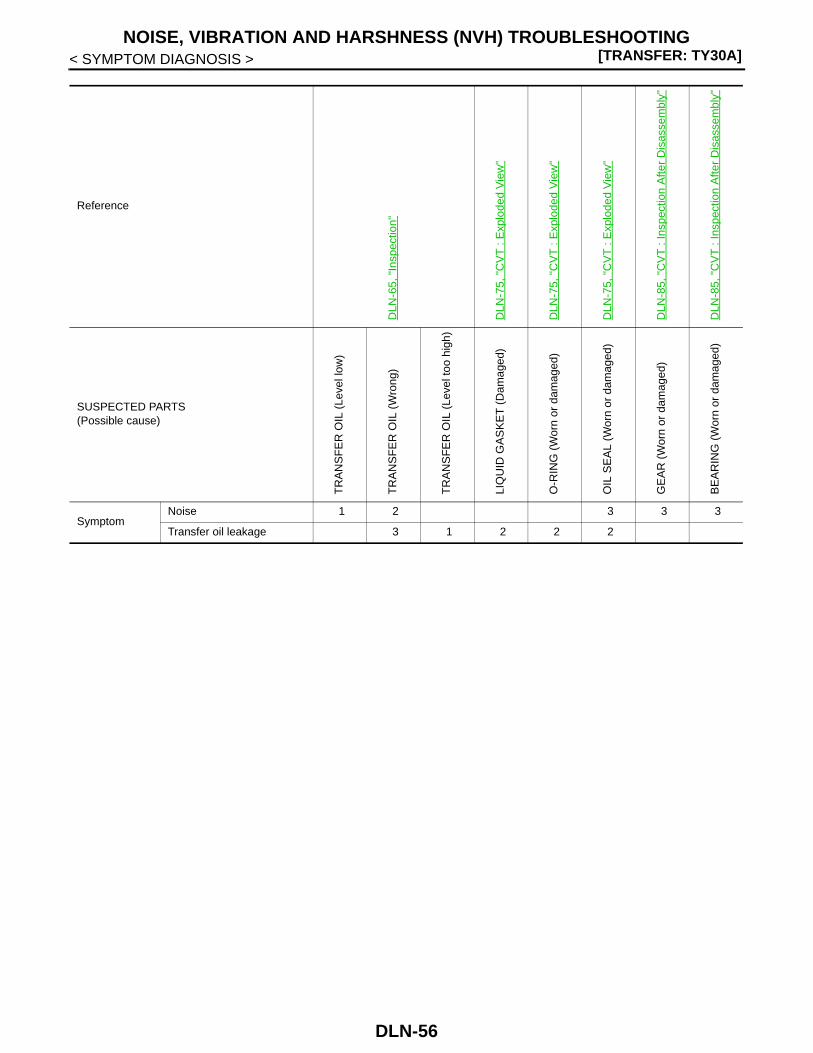
[TRANSFER: TY30A]NOISE, VIBRATION AND HARSHNESS (NVH) TROUBLESHOOTING
< SYMPTOM DIAGNOSIS >
Reference
DLN
-65,
"In
spec
tion"
DLN
-75,
"C
VT
: E
xplo
ded
Vie
w"
DLN
-75,
"C
VT
: E
xplo
ded
Vie
w"
DLN
-75,
"C
VT
: E
xplo
ded
Vie
w"
DLN
-85,
"C
VT
: In
spec
tion
Afte
r D
isas
sem
bly"
DLN
-85,
"C
VT
: In
spec
tion
Afte
r D
isas
sem
bly"
SUSPECTED PARTS(Possible cause)
TR
AN
SF
ER
OIL
(Le
vel l
ow)
TR
AN
SF
ER
OIL
(W
rong
)
TR
AN
SF
ER
OIL
(Le
vel t
oo h
igh)
LIQ
UID
GA
SK
ET
(D
amag
ed)
O-R
ING
(W
orn
or d
amag
ed)
OIL
SE
AL
(Wor
n or
dam
aged
)
GE
AR
(W
orn
or d
amag
ed)
BE
AR
ING
(W
orn
or d
amag
ed)
SymptomNoise 1 2 3 3 3
Transfer oil leakage 3 1 2 2 2
DLN-56

PRECAUTIONS[TRANSFER: TY30A]
C
E
F
G
H
I
J
K
L
M
A
B
LN
N
O
P
< PRECAUTION >
D
PRECAUTIONPRECAUTIONS
Precaution for Supplemental Restraint System (SRS) "AIR BAG" and "SEAT BELT PRE-TENSIONER" INFOID:0000000001308763
The Supplemental Restraint System such as “AIR BAG” and “SEAT BELT PRE-TENSIONER”, used alongwith a front seat belt, helps to reduce the risk or severity of injury to the driver and front passenger for certaintypes of collision. Information necessary to service the system safely is included in the “SRS AIRBAG” and“SEAT BELT” of this Service Manual.WARNING:• To avoid rendering the SRS inoperative, which could increase the risk of personal injury or death in
the event of a collision which would result in air bag inflation, all maintenance must be performed byan authorized NISSAN/INFINITI dealer.
• Improper maintenance, including incorrect removal and installation of the SRS, can lead to personalinjury caused by unintentional activation of the system. For removal of Spiral Cable and Air BagModule, see the “SRS AIRBAG”.
• Do not use electrical test equipment on any circuit related to the SRS unless instructed to in thisService Manual. SRS wiring harnesses can be identified by yellow and/or orange harnesses or har-ness connectors.
Precaution for Procedure without Cowl Top Cover INFOID:0000000001470347
When performing the procedure after removing cowl top cover, coverthe lower end of windshield with urethane, etc.
Service Notice or Precautions for Transfer INFOID:0000000001278546
CAUTION:• After overhaul refill the transfer with new transfer oil.• Check the oil level or replace the oil only with the vehicle parked on level surface.• During removal or installation, keep inside of transfer clear of dust or dirt.• Replace all tires at the same time. Always use tires of the proper size and the same brand and pat-
tern. Fitting improper size and unusual wear tires applies excessive force to vehicle mechanism andcan cause longitudinal vibration.
• Disassembly should be done in a clean work area.• Before proceeding with disassembly, thoroughly clean the transfer. It is important to prevent the
internal parts from becoming contaminated by dirt or other foreign matter.• Check for the correct installation status prior to removal or disassembly. If matching marks are
required, be certain they do not interfere with the function of the parts when applied.• All parts should be carefully cleaned with a general purpose, non-flammable solvent before inspec-
tion or reassembly.• Check appearance of the disassembled parts for damage, deformation, and unusual wear. Replace
them with a new one if necessary.• Gaskets, seals, O-rings and lock nuts should be replaced any time when the transfer is disassem-
bled.• In principle, tighten bolts or nuts gradually in several steps working diagonally from inside to out-
side. If tightening sequence is specified, use it.• Observe the specified torque when assembling.• Clean and flush the parts sufficiently and blow-dry them.• Be careful not to damage sliding surfaces and mating surfaces.
PIIB3706J
DLN-57

[TRANSFER: TY30A]PRECAUTIONS
< PRECAUTION >• Use lint-free cloth or towels for wiping parts clean. Common shop rags can leave fibers that could
interfere with the operation of the transfer.
DLN-58

PREPARATION[TRANSFER: TY30A]
C
E
F
G
H
I
J
K
L
M
A
B
LN
N
O
P
< PREPARATION >
D
PREPARATIONPREPARATIONM/T, A/T
M/T, A/T : Special Service Tools INFOID:0000000001278547
Tool numberTool name
Description
ST30720000Drift a: φ77 mm (3.03 in) dia.b: φ55.5 mm (2.185 in) dia.
• Installing adapter case oil seal (inner/outer)• Installing drive pinion oil seal
ST27861000Drift a: φ62 mm (2.44 in) dia.b: φ52 mm (2.05 in) dia.
• Installing adapter case oil seal (inner/outer)• Installing drive pinion oil seal
ST22730000Replacer
• Removing inner race of ring gear shaft bear-ing (transfer case side)
• Removing inner race of drive pinion bearing (front side)
ST33052000Drift a: φ22 mm (0.87 in) dia.b: φ28 mm (1.10 in) dia.
• Removing ring gear• Removing inner race of drive pinion bearing
(front side)
ST01530000Drift a: φ48 mm (1.89 in) dia.b: φ41 mm (1.61 in) dia.
Installing ring gear
ST35272000Drifta: φ72 mm (2.83 in) dia.b: φ40 mm (1.57 in) dia.c: φ35.5 mm (1.398 in) dia.
• Installing ring gear• Installing outer race of drive pinion bearing
(front side)
NT115
ZZA1003D
ZZA0700D
NT116
ZZA0534D
NT107
DLN-59

[TRANSFER: TY30A]PREPARATION
< PREPARATION >
KV10111400Drift a: φ25 mm (0.98 in) dia.b: φ20.8 mm (0.819 in) dia.
Installing inner race of ring gear shaft bearing (transfer case side)
KV381054S0Puller
Removing drive pinion oil seal
ST23860000Drift a: φ38 mm (1.50 in) dia.b: φ33 mm (1.30 in) dia.
Installing inner race of drive pinion bearing (front side)
ST3127S000Preload gauge
Measuring preload torque
ST38280000Bushing remover
Installing outer race of drive pinion bearing (front side)
ST33230000Drift a: φ51 mm (2.01 in) dia.
Installing outer race of drive pinion bearing (rear side)
Tool numberTool name
Description
ZZA1003D
ZZA0601D
ZZA0534D
ZZA0503D
NT685
ZZA0938D
DLN-60
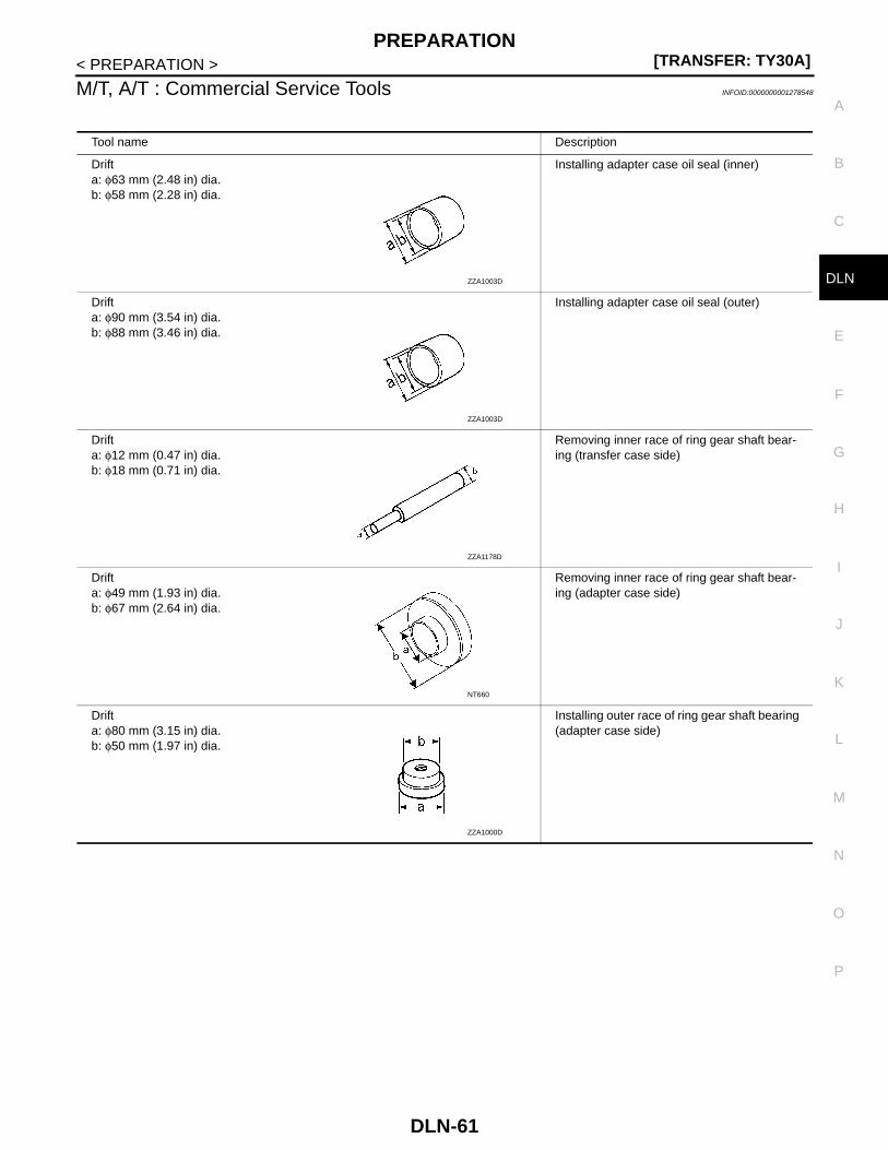
PREPARATION[TRANSFER: TY30A]
C
E
F
G
H
I
J
K
L
M
A
B
LN
N
O
P
< PREPARATION >
D
M/T, A/T : Commercial Service Tools INFOID:0000000001278548
Tool name Description
Drift a: φ63 mm (2.48 in) dia.b: φ58 mm (2.28 in) dia.
Installing adapter case oil seal (inner)
Drift a: φ90 mm (3.54 in) dia.b: φ88 mm (3.46 in) dia.
Installing adapter case oil seal (outer)
Drift a: φ12 mm (0.47 in) dia.b: φ18 mm (0.71 in) dia.
Removing inner race of ring gear shaft bear-ing (transfer case side)
Drift a: φ49 mm (1.93 in) dia.b: φ67 mm (2.64 in) dia.
Removing inner race of ring gear shaft bear-ing (adapter case side)
Drift a: φ80 mm (3.15 in) dia.b: φ50 mm (1.97 in) dia.
Installing outer race of ring gear shaft bearing (adapter case side)
ZZA1003D
ZZA1003D
ZZA1178D
NT660
ZZA1000D
DLN-61

[TRANSFER: TY30A]PREPARATION
< PREPARATION >
CVT
CVT : Special Service Tools INFOID:0000000001278549
Drift a: φ57 mm (2.24 in) dia.b: φ47 mm (1.85 in) dia.
Installing inner race of ring gear shaft bearing (adapter case side)
Drift a: φ61 mm (2.40 in) dia.b: φ48 mm (1.89 in) dia.
Installing outer race of drive pinion bearing (front side)
Tool name Description
ZZA1003D
ZZA1000D
Tool numberTool name
Description
ST30720000Drift a: φ77 mm (3.03 in) dia.b: φ55.5 mm (2.185 in) dia.
• Installing adapter case oil seal• Installing drive pinion oil seal
ST27861000Drift a: φ62 mm (2.44 in) dia.b: φ52 mm (2.05 in) dia.
• Installing adapter case oil seal• Installing drive pinion oil seal
KV40104830Drift a: φ70 mm (2.76 in) dia.b: φ63.5 mm (2.500 in) dia.
Installing adapter case oil seal
ST22730000Replacer
• Removing inner race of ring gear shaft bear-ing (transfer case side)
• Removing inner race of drive pinion bearing (front side)
NT115
ZZA1003D
ZZA1003D
ZZA0700D
DLN-62

PREPARATION[TRANSFER: TY30A]
C
E
F
G
H
I
J
K
L
M
A
B
LN
N
O
P
< PREPARATION >
D
ST33052000Drift a: φ22 mm (0.87 in) dia.b: φ28 mm (1.10 in) dia.
• Removing ring gear• Removing inner race of drive pinion bearing
(front side)
ST30621000Drift a: φ72 mm (2.83 in) dia.b: φ48 mm (1.89 in) dia.
• Installing outer race of ring gear shaft bear-ing (adapter case side)
• Installing outer race of drive pinion bearing (front side)
ST01530000Drift a: φ48 mm (1.89 in) dia.b: φ41 mm (1.61 in) dia.
Installing ring gear
ST35272000Drifta: φ72 mm (2.83 in) dia.b: φ40 mm (1.57 in) dia.c: φ35.5 mm (1.398 in) dia.
• Installing ring gear• Installing outer race of drive pinion bearing
(front side)
KV10111400Drift a: φ25 mm (0.98 in) dia.b: φ20.8 mm (0.819 in) dia.
Installing inner race of ring gear shaft bearing (transfer case side)
KV381054S0Puller
Removing drive pinion oil seal
ST23860000Drift a: φ38 mm (1.50 in) dia.b: φ33 mm (1.30 in) dia.
Installing inner race of drive pinion bearing (front side)
Tool numberTool name
Description
NT116
ZZA1000D
ZZA0534D
NT107
ZZA1003D
ZZA0601D
ZZA0534D
DLN-63

[TRANSFER: TY30A]PREPARATION
< PREPARATION >
CVT : Commercial Service Tools INFOID:0000000001278550
ST3127S000Preload gauge
Measuring preload torque
ST38280000Bushing remover
Installing outer race of drive pinion bearing (front side)
ST33230000Drift a: φ51 mm (2.01 in) dia.
Installing outer race of drive pinion bearing (rear side)
Tool numberTool name
Description
ZZA0503D
NT685
ZZA0938D
Tool name Description
Drift a: φ12 mm (0.47 in) dia.b: φ18 mm (0.71 in) dia.
Removing inner race of ring gear shaft bear-ing (transfer case side)
Drift a: φ49 mm (1.93 in) dia.b: φ67 mm (2.64 in) dia.
Removing inner race of ring gear shaft bear-ing (adapter case side)
Drift a: φ57 mm (2.24 in) dia.b: φ47 mm (1.85 in) dia.
Installing inner race of ring gear shaft bearing (adapter case side)
ZZA1178D
NT660
ZZA1003D
DLN-64

TRANSFER OIL[TRANSFER: TY30A]
C
E
F
G
H
I
J
K
L
M
A
B
LN
N
O
P
< ON-VEHICLE MAINTENANCE >
D
ON-VEHICLE MAINTENANCETRANSFER OIL
Inspection INFOID:0000000001278551
OIL LEAKAGECheck transfer surrounding area (oil seal, drain plug, filler plug, and transfer case, etc.) for oil leakage.
OIL LEVEL1. Remove filler plug (1) and gasket. Then check that oil is filled up
(A) from mounting hole for the filler plug.2. Before installing filler plug, set a new gasket. Install filler plug on
transfer and tighten to the specified torque. Refer to DLN-72,"M/T, A/T : Exploded View" (M/T, A/T), DLN-75, "CVT : ExplodedView" (CVT).CAUTION:Never reuse gaskets.
Draining INFOID:0000000001278552
1. Run the vehicle to warm up the transfer unit sufficiently.2. Stop the engine and remove drain plug (1) and gaskets to drain
the transfer oil.CAUTION:Never remove tooth contact test hole plug (2).
3. Before installing drain plug, set a new gasket. Install drain plugon transfer and tighten to the specified torque. Refer to DLN-72,"M/T, A/T : Exploded View" (M/T, A/T), DLN-75, "CVT : ExplodedView" (CVT).CAUTION:Never reuse gaskets.
Refilling INFOID:0000000001278553
1. Remove filler plug (1) and gasket. Then fill oil up to mountinghole (A) for the filler plug.
CAUTION:Carefully fill the oil. (Fill up for approximately 3 minutes.)
2. Leave the vehicle for 3 minutes. Then check oil level again.3. Before installing filler plug, set a new gasket. Install filler plug on
transfer and tighten to the specified torque. Refer to DLN-72, "M/T, A/T : Exploded View" (M/T, A/T), DLN-75, "CVT : Exploded View" (CVT).CAUTION:Never reuse gasket.
SDIA3060J
SDIA3059J
Oil grade and viscosity : Refer to MA-22, "Fluids and Lubricants".
Oil capacity : Refer to DLN-118, "Gener-al Specifications".
SDIA3060J
DLN-65

[TRANSFER: TY30A]4WD CONTROL UNIT
< ON-VEHICLE REPAIR >
ON-VEHICLE REPAIR4WD CONTROL UNITLHD
LHD : Exploded View INFOID:0000000001278554
LHD : Removal and Installation INFOID:0000000001278555
REMOVAL1. Remove the glove box cover assembly. Refer to IP-11, "Exploded View".2. Disconnect 4WD control unit harness connector.3. Remove 4WD control unit (1) mounting bolts.4. Remove 4WD control unit.
INSTALLATIONInstall is the reverse order of removal.RHD
1. 4WD control unit
: Vehicle front
JSDIA0271ZZ
JSDIA0272ZZ
DLN-66
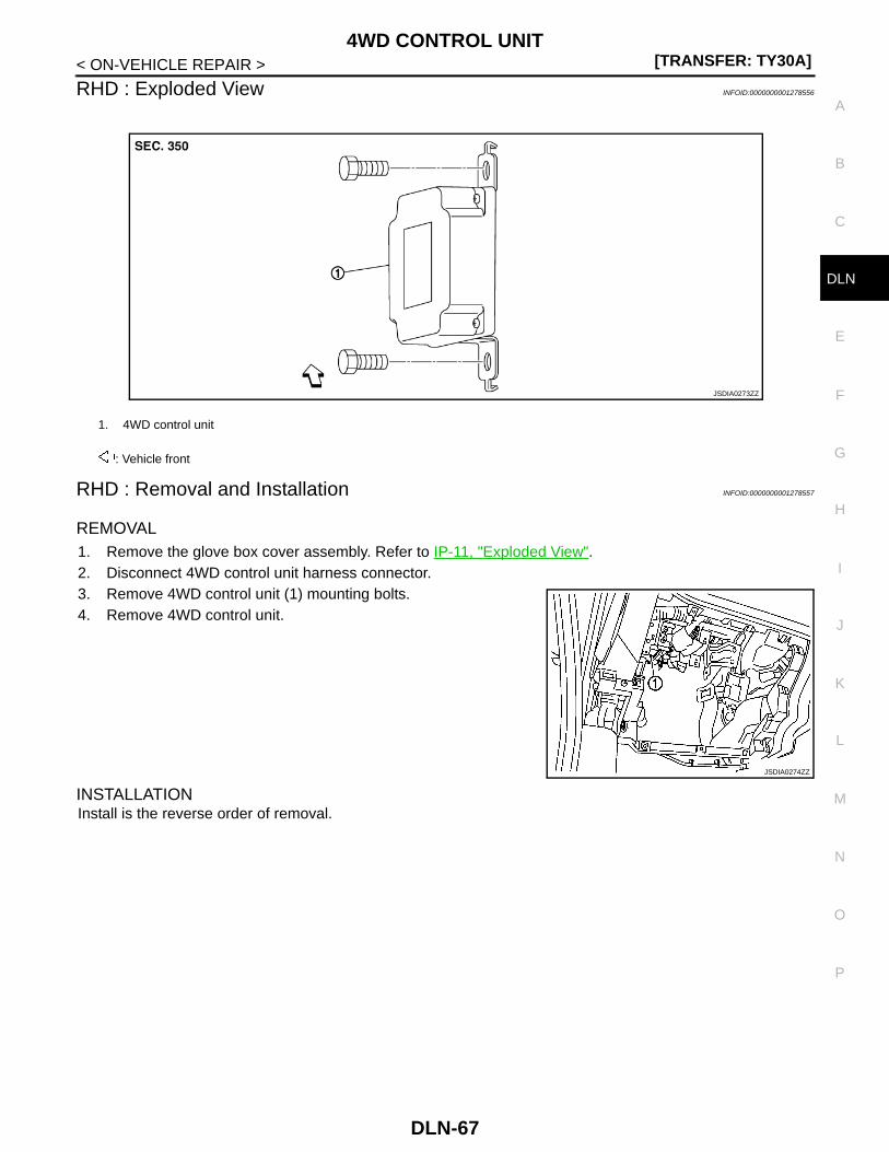
4WD CONTROL UNIT[TRANSFER: TY30A]
C
E
F
G
H
I
J
K
L
M
A
B
LN
N
O
P
< ON-VEHICLE REPAIR >
D
RHD : Exploded View INFOID:0000000001278556
RHD : Removal and Installation INFOID:0000000001278557
REMOVAL1. Remove the glove box cover assembly. Refer to IP-11, "Exploded View".2. Disconnect 4WD control unit harness connector.3. Remove 4WD control unit (1) mounting bolts.4. Remove 4WD control unit.
INSTALLATIONInstall is the reverse order of removal.
1. 4WD control unit
: Vehicle front
JSDIA0273ZZ
JSDIA0274ZZ
DLN-67

[TRANSFER: TY30A]TRANSFER ASSEMBLY
< REMOVAL AND INSTALLATION >
REMOVAL AND INSTALLATIONTRANSFER ASSEMBLYMR20DE (M/T), QR25DE (M/T)
MR20DE (M/T), QR25DE (M/T) : Exploded View INFOID:0000000001278558
MR20DE (M/T), QR25DE (M/T) : Removal and Installation INFOID:0000000001278559
REMOVAL1. Remove the following parts.
• Exhaust front tube; refer to EX-5, "Exploded View" (MR20DE), EX-10, "Exploded View" (QR25DE).• Exhaust manifold; refer to EM-30, "Exploded View" (MR20DE).• Exhaust center tube; refer to EX-10, "Exploded View" (QR25DE).
2. Separate the rear propeller shaft. Refer to DLN-121, "Exploded View".3. Remove right side drive shaft and support bearing bracket. Refer to FAX-52, "MR20DE : Exploded View"
(MR20DE), FAX-60, "QR25DE : Exploded View" (QR25DE).
4. Remove the mounting bolts ( ) of transaxle assembly andtransfer assembly.CAUTION:Never remove the mounting bolts ( ) of adapter case.
5. Remove transfer assembly from the vehicle.CAUTION:• Never damage ring gear shaft.• Never damage air breather hose.
6. Remove O-ring (outer) from the transfer assembly.
INSTALLATIONNote the following, and install in the reverse order of removal.• Apply multi-purpose grease lightly and evenly onto an O-ring (outer), and install it to the transfer assembly.
1. Transfer assembly 2. O-ring (outer)
: Vehicle front
: Apply multi-purpose grease.
Refer to GI-4, "Components" for symbols not described on the above.
JSDIA0210GB
SDIA3225J
DLN-68

TRANSFER ASSEMBLY[TRANSFER: TY30A]
C
E
F
G
H
I
J
K
L
M
A
B
LN
N
O
P
< REMOVAL AND INSTALLATION >
D
CAUTION:Never reuse O-ring (outer).
• Install mounting bolts according to the standard below when install-ing transfer assembly to the transaxle assembly.
• Check oil level and check for oil leakage after installation. Refer toDLN-65, "Inspection".
MR20DE (CVT), QR25DE (CVT)
MR20DE (CVT), QR25DE (CVT) : Exploded View INFOID:0000000001312102
MR20DE (CVT), QR25DE (CVT) : Removal and Installation INFOID:0000000001312103
REMOVAL1. Remove the following parts.
• Exhaust front tube; refer to EX-5, "Exploded View" (MR20DE), EX-10, "Exploded View" (QR25DE).• Exhaust manifold; refer to EM-30, "Exploded View" (MR20DE).• Exhaust center tube; refer to EX-10, "Exploded View" (QR25DE).
2. Separate the rear propeller shaft. Refer to DLN-121, "Exploded View".3. Remove right side drive shaft and support bearing bracket. Refer to FAX-52, "MR20DE : Exploded View"
(MR20DE), FAX-60, "QR25DE : Exploded View" (QR25DE).
Bolt symbol A B
Installation direction Transfer ⇒ Transaxle Transaxle ⇒ Transfer
SDIA3070J
1. Transfer assembly
: Vehicle front
Refer to GI-4, "Components" for symbols in the figure.
JSDIA0209GB
DLN-69

[TRANSFER: TY30A]TRANSFER ASSEMBLY
< REMOVAL AND INSTALLATION >
4. Remove the mounting bolts ( ) of transaxle assembly andtransfer assembly.CAUTION:Never remove the mounting bolts ( ) of adapter case.
5. Remove transfer assembly from the vehicle.CAUTION:• Never damage ring gear shaft.• Never damage air breather hose.
INSTALLATIONNote the following, and install in the reverse order of removal.• Install mounting bolts according to the standard below when install-
ing transfer assembly to the transaxle assembly.
CAUTION:• When installing transfer assembly to transaxle assembly,
replace the side oil seal (transfer joint). Refer to TM-533,"MR20DE : Exploded View" (MR20DE), TM-534, "QR25DE :Exploded View" (QR25DE).
• Never damage side seal (the joint part of transfer) and dustcover of transaxle assembly.
• Check oil level and check for oil leakage after installation. Refer to DLN-65, "Inspection".M9R
M9R : Exploded View INFOID:0000000001279177
SDIA3225J
Bolt symbol A B
Installation direction Transfer ⇒ Transaxle Transaxle ⇒ Transfer
SDIA3070J
1. Gusset 2. Transfer assembly 3. O-ring (outer)
JSDIA0267GB
DLN-70

TRANSFER ASSEMBLY[TRANSFER: TY30A]
C
E
F
G
H
I
J
K
L
M
A
B
LN
N
O
P
< REMOVAL AND INSTALLATION >
D
M9R : Removal and Installation INFOID:0000000001279178
REMOVAL1. Remove the exhaust front tube. Refer to EX-14, "Exploded View".2. Separate the rear propeller shaft. Refer to DLN-121, "Exploded View".3. Remove right side drive shaft and support bearing bracket. Refer to FAX-68, "M9R : Exploded View".4. Remove bracket, turbocharger cooling pump and water hose. Refer to EM-275, "Exploded View".5. Remove the mounting bolts of catalyst cover. Refer to EM-273, "Exploded View".6. Remove the mounting bolts of water pipe. Refer to FAX-68, "M9R : Exploded View".7. Remove the gusset.8. Separate the rear torque rod from rear engine mounting bracket. Refer to EM-312, "Exploded View".
9. Remove the mounting bolts ( ) of transaxle assembly andtransfer assembly.CAUTION:Never remove the mounting bolts ( ) of adapter case.
10. Remove transfer assembly from the vehicle.CAUTION:• Never damage ring gear shaft.• Never damage air breather hose.
11. Remove O-ring (outer) from the transfer assembly.
INSTALLATIONNote the following, and install in the reverse order of removal.• Apply multi-purpose grease lightly and evenly onto an O-ring (outer), and install it to the transfer assembly.
CAUTION:Never reuse O-ring (outer).
• Install mounting bolts according to the standard below when install-ing transfer assembly to the transaxle assembly.
• Check oil level and check for oil leakage after installation. Refer toDLN-65, "Inspection".
: Vehicle front
: Apply multi-purpose grease.
Refer to GI-4, "Components" for symbols not described on the above.
SDIA3225J
Bolt symbol A B
Installation direction Transfer ⇒ Transaxle Transaxle ⇒ Transfer
SDIA3070J
DLN-71

[TRANSFER: TY30A]ADAPTER CASE
< DISASSEMBLY AND ASSEMBLY >
DISASSEMBLY AND ASSEMBLYADAPTER CASEM/T, A/T
M/T, A/T : Exploded View INFOID:0000000001278562
1. Adapter case oil seal (outer) 2. O-ring (outer) 3. Adapter case oil seal (inner)
4. Adapter case 5. O-ring (inner) 6. Ring gear shaft
7. Ring gear adjusting shim(adapter case side)
8. Ring gear shaft bearing(adapter case side)
9. Ring gear
10. Ring gear nut 11. Ring gear shaft bearing(transfer case side)
12. Ring gear adjusting shim(transfer case side)
13. Transfer case 14. Air breather hose 15. Air breather tube
16. Gasket 17. Filler plug 18. Drain plug
19. Plug 20. Drive pinion 21. Drive pinion adjusting shim
22. Drive pinion bearing (front side) 23. Collapsible spacer 24. Drive pinion bearing (rear side)
25. Drive pinion oil seal 26. Companion flange 27. Lock nut
A: Oil seal lip
JSDIA0319GB
DLN-72
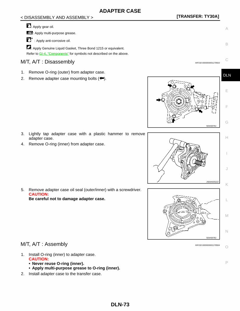
ADAPTER CASE[TRANSFER: TY30A]
C
E
F
G
H
I
J
K
L
M
A
B
LN
N
O
P
< DISASSEMBLY AND ASSEMBLY >
D
M/T, A/T : Disassembly INFOID:0000000001278563
1. Remove O-ring (outer) from adapter case.
2. Remove adapter case mounting bolts ( ).
3. Lightly tap adapter case with a plastic hammer to removeadapter case.
4. Remove O-ring (inner) from adapter case.
5. Remove adapter case oil seal (outer/inner) with a screwdriver.CAUTION:Be careful not to damage adapter case.
M/T, A/T : Assembly INFOID:0000000001278564
1. Install O-ring (inner) to adapter case.CAUTION:• Never reuse O-ring (inner).• Apply multi-purpose grease to O-ring (inner).
2. Install adapter case to the transfer case.
: Apply gear oil.
: Apply multi-purpose grease.
: Apply anti-corrosive oil.
: Apply Genuine Liquid Gasket, Three Bond 1215 or equivalent.
Refer to GI-4, "Components" for symbols not described on the above.
SDIA3076J
JSDIA0252ZZ
SDIA3078J
DLN-73

[TRANSFER: TY30A]ADAPTER CASE
< DISASSEMBLY AND ASSEMBLY >
3. Apply anti-corrosive oil onto threads and seats of bolts ( ), andtighten with the specified torque.
4. Check backlash, tooth contact, total preload and companionflange runout. Refer to DLN-89, "M/T, A/T : Adjustment".CAUTION:Measure the total preload without the adapter case oil seal(outer/inner).
5. Install adapter case oil seal (inner) (1) to the adapter case withdrifts.
CAUTION:• Never reuse oil seal.• Apply multi-purpose grease onto oil seal lips, and gear oil
onto the circumference.• Install adapter case oil seal (inner) in the direction shown in the figure.
6. Install adapter case oil seal (outer) (1) to the adapter case withdrifts so that it becomes flush with adapter case end surface.
CAUTION:• Never reuse oil seal.• Apply multi-purpose grease onto oil seal lips, and gear oil
onto the circumference.• Install adapter case oil seal (outer) in the direction shown
in the figure.7. Install O-ring (outer) to the adapter case.
M/T, A/T : Inspection After Disassembly INFOID:0000000001278565
Check items below. If necessary, replace them with new ones.
CASECheck the bearing mounting surface for wear, cracks and damages.CVT
SDIA3076J
A : Drift (SST: ST30720000)
B : Drift (SST: ST27861000)
C : Drift (commercial service tool)
Dimension “D” : 0 – 1.0 mm
A : Drift (SST: ST30720000)
B : Drift (SST: ST27861000)
C : Drift (commercial service tool)
JSDIA0259ZZ
JSDIA0214ZZ
DLN-74

ADAPTER CASE[TRANSFER: TY30A]
C
E
F
G
H
I
J
K
L
M
A
B
LN
N
O
P
< DISASSEMBLY AND ASSEMBLY >
D
CVT : Exploded View INFOID:0000000001278566
1. Adapter case oil seal 2. Adapter case 3. O-ring
4. Ring gear shaft 5. Ring gear adjusting shim(adapter case side)
6. Ring gear shaft bearing(adapter case side)
7. Ring gear 8. Ring gear nut 9. Ring gear shaft bearing(transfer case side)
10. Ring gear adjusting shim(transfer case side)
11. Transfer case 12. Air breather hose
13. Air breather tube 14. Gasket 15. Filler plug
16. Drain plug 17. Plug 18. Drive pinion
19. Drive pinion adjusting shim 20. Drive pinion bearing (front side) 21. Collapsible spacer
22. Drive pinion bearing (rear side) 23. Drive pinion oil seal 24. Companion flange
25. Lock nut
A: Oil seal lip
: Apply gear oil.
: Apply multi-purpose grease.
: Apply anti-corrosive oil.
JSDIA0320GB
DLN-75

[TRANSFER: TY30A]ADAPTER CASE
< DISASSEMBLY AND ASSEMBLY >
CVT : Disassembly INFOID:0000000001278567
1. Remove adapter case mounting bolts ( ).
2. Lightly tap adapter case with a plastic hammer to removeadapter case.
3. Remove O-ring from adapter case.
4. Remove adapter case oil seal with a screwdriver.CAUTION:Be careful not to damage adapter case.
CVT : Assembly INFOID:0000000001278568
1. Install O-ring to adapter case.CAUTION:• Never reuse O-ring.• Apply multi-purpose grease to O-ring.
2. Install adapter case to the transfer case.
: Apply Genuine Liquid Gasket, Three Bond 1215 or equivalent.
Refer to GI-4, "Components" for symbols not described on the above.
SDIA3076J
SDIA3077J
SDIA3078J
DLN-76

ADAPTER CASE[TRANSFER: TY30A]
C
E
F
G
H
I
J
K
L
M
A
B
LN
N
O
P
< DISASSEMBLY AND ASSEMBLY >
D
3. Apply anti-corrosive oil onto threads and seats of bolts ( ), andtighten with the specified torque.
4. Check backlash, tooth contact, total preload and companionflange runout. Refer to DLN-102, "CVT : Adjustment".CAUTION:Measure the total preload without the adapter case oil seal.
5. Install adapter case oil seal (1) to the adapter case with drifts.
CAUTION:• Never reuse adapter case oil seal.• Apply multi-purpose grease onto oil seal lips, and gear oil
onto the circumference.
CVT : Inspection After Disassembly INFOID:0000000001278569
Check items below. If necessary, replace them with new ones.
CASECheck the bearing mounting surface for wear, cracks and damages.
SDIA3076J
A : Drift (SST: ST30720000)
B : Drift (SST: ST27861000)
C : Drift (SST: KV40104830)
Dimension “D” : 0.5 – 1.5 mm
JSDIA0226ZZ
DLN-77

[TRANSFER: TY30A]RING GEAR SHAFT
< DISASSEMBLY AND ASSEMBLY >
RING GEAR SHAFTM/T, A/T
M/T, A/T : Exploded View INFOID:0000000001349309
1. Adapter case oil seal (outer) 2. O-ring (outer) 3. Adapter case oil seal (inner)
4. Adapter case 5. O-ring (inner) 6. Ring gear shaft
7. Ring gear adjusting shim(adapter case side)
8. Ring gear shaft bearing(adapter case side)
9. Ring gear
10. Ring gear nut 11. Ring gear shaft bearing(transfer case side)
12. Ring gear adjusting shim(transfer case side)
13. Transfer case 14. Air breather hose 15. Air breather tube
16. Gasket 17. Filler plug 18. Drain plug
19. Plug 20. Drive pinion 21. Drive pinion adjusting shim
22. Drive pinion bearing (front side) 23. Collapsible spacer 24. Drive pinion bearing (rear side)
25. Drive pinion oil seal 26. Companion flange 27. Lock nut
A: Oil seal lip
: Apply gear oil.
: Apply multi-purpose grease.
JSDIA0319GB
DLN-78

RING GEAR SHAFT[TRANSFER: TY30A]
C
E
F
G
H
I
J
K
L
M
A
B
LN
N
O
P
< DISASSEMBLY AND ASSEMBLY >
D
M/T, A/T : Disassembly INFOID:0000000001278571
1. Remove adapter case. Refer to DLN-73, "M/T, A/T : Disassembly".2. Remove adapter case oil seal (outer/inner) from the adapter case. Refer to DLN-73, "M/T, A/T : Disassem-
bly".3. Tap the ring gear adjusting shim from the cutout on the adapter
case with a brass rod to remove ring gear shaft bearing outerrace (adapter case side) and ring gear adjusting shim (adaptercase side).CAUTION:Be careful not to damage adapter case.
4. Remove ring gear shaft assembly from the transfer case.5. Remove outer race of ring gear shaft bearing (transfer case
side) and ring gear adjusting shim (transfer case side) from thetransfer case.
6. Remove inner race of ring gear shaft bearing (transfer caseside) from ring gear shaft with drift (A) (commercial service tool)and replacer (B) (SST: ST22730000).
7. Remove ring gear nut (1).CAUTION:Never damage ring gear shaft.
8. Remove ring gear from ring gear shaft with a drift (A) (SST:ST33052000).
: Apply anti-corrosive oil.
: Apply Genuine Liquid Gasket, Three Bond 1215 or equivalent.
Refer to GI-4, "Components" for symbols not described on the above.
SDIA3079J
SDIA3080J
SDIA3081J
SDIA3082J
DLN-79

[TRANSFER: TY30A]RING GEAR SHAFT
< DISASSEMBLY AND ASSEMBLY >9. Remove inner race of ring gear shaft bearing (adapter case
side) from ring gear with a drift (A) (commercial service tool) andreplacer.
M/T, A/T : Assembly INFOID:0000000001278572
1. Select ring gear adjusting shim (transfer case side). Refer to DLN-89, "M/T, A/T : Adjustment".2. Assemble the selected ring gear adjusting shim (transfer case side) and outer races of ring gear shaft
bearing (transfer case side) to the transfer case.CAUTION:• Never reuse ring gear shaft bearing (transfer case side).• Apply gear oil to the ring gear shaft bearing (transfer case side).
3. Select ring gear adjusting shim (adapter case side). Refer to DLN-89, "M/T, A/T : Adjustment".4. Install the selected ring gear adjusting shim (adapter case side) to the adapter case.5. Install outer race of ring gear shaft bearing (adapter case side)
to the adapter case with a drift (A) (commercial service tool).CAUTION:• Never reuse ring gear shaft bearing (adapter case side).• Apply gear oil to the ring gear shaft bearing (adapter case
side).
6. Install inner race of ring gear shaft bearing (adapter case side)to the ring gear with drifts.
CAUTION:• Never reuse ring gear shaft bearing (adapter case side).• Apply gear oil to the ring gear shaft bearing (adapter case
side).
7. Apply anti-corrosive oil to the spline of ring gear shaft. Install thering gear to ring gear shaft with drifts.
SDIA3083J
SDIA3102J
A : Press adapter (If necessary)
B : Drift (commercial service tool)
SDIA3097J
A : Drift (SST: ST01530000)
B : Drift (SST: ST35272000)
JSDIA0253ZZ
DLN-80

RING GEAR SHAFT[TRANSFER: TY30A]
C
E
F
G
H
I
J
K
L
M
A
B
LN
N
O
P
< DISASSEMBLY AND ASSEMBLY >
D
8. Apply anti-corrosive oil to threads and seats of ring gear nut.Tighten the ring gear nut with the specified torque by using atorque wrench.CAUTION:• Never reuse ring gear nut.• Never damage ring gear shaft.
9. Install inner race of ring gear shaft bearing (transfer case side)to the ring gear shaft with a drift (A) (SST: KV10111400).CAUTION:• Never reuse ring gear shaft bearing (transfer case side).• Apply gear oil to the ring gear shaft bearing (transfer race
side).10. Assemble the ring gear shaft assembly to the transfer case.11. Install adapter case. Refer to DLN-73, "M/T, A/T : Assembly".12. Check backlash, tooth contact, total preload and companion
flange runout. Refer to DLN-89, "M/T, A/T : Adjustment".CAUTION:Measure the total preload without the adapter case oil seal.
13. Install adapter case oil seal (outer/inner) to the adapter case. Refer to DLN-73, "M/T, A/T : Assembly".
M/T, A/T : Inspection After Disassembly INFOID:0000000001278573
Check items below. If necessary, replace them with new ones.
GEAR AND SHAFTCheck gear face and shaft for wear, cracks, damage, and seizure.CAUTION:Replace ring gear and drive pinion as a set (hypoid gear set) if any malfunction is detected on the ringgear or drive pinion.
BEARINGCheck for seizure, peeling, wear, corrosion, sticking, unusual noise, roughness in hand turning, and otherdamage.CAUTION:Always replace inner race and outer race as a pair when replacing the bearing.
SHIMCheck for seizure, damage, and unusual wear.
CASECheck the bearing mounting surface for wear, cracks and damages.CVT
SDIA3100J
JSDIA0254ZZ
DLN-81

[TRANSFER: TY30A]RING GEAR SHAFT
< DISASSEMBLY AND ASSEMBLY >
CVT : Exploded View INFOID:0000000001349313
1. Adapter case oil seal 2. Adapter case 3. O-ring
4. Ring gear shaft 5. Ring gear adjusting shim(adapter case side)
6. Ring gear shaft bearing(adapter case side)
7. Ring gear 8. Ring gear nut 9. Ring gear shaft bearing(transfer case side)
10. Ring gear adjusting shim(transfer case side)
11. Transfer case 12. Air breather hose
13. Air breather tube 14. Gasket 15. Filler plug
16. Drain plug 17. Plug 18. Drive pinion
19. Drive pinion adjusting shim 20. Drive pinion bearing (front side) 21. Collapsible spacer
22. Drive pinion bearing (rear side) 23. Drive pinion oil seal 24. Companion flange
25. Lock nut
A: Oil seal lip
: Apply gear oil.
: Apply multi-purpose grease.
: Apply anti-corrosive oil.
JSDIA0320GB
DLN-82

RING GEAR SHAFT[TRANSFER: TY30A]
C
E
F
G
H
I
J
K
L
M
A
B
LN
N
O
P
< DISASSEMBLY AND ASSEMBLY >
D
CVT : Disassembly INFOID:0000000001278575
1. Remove adapter case. Refer to DLN-76, "CVT : Disassembly".2. Remove adapter case oil seal from the adapter case. Refer to DLN-76, "CVT : Disassembly".3. Tap the ring gear adjusting shim from the cutout on the adapter
case with a brass rod to remove ring gear shaft bearing outerrace (adapter case side) and ring gear adjusting shim (adaptercase side).CAUTION:Be careful not to damage adapter case.
4. Remove ring gear shaft assembly from the transfer case.5. Remove outer race of ring gear shaft bearing (transfer case
side) and ring gear adjusting shim (transfer case side) from thetransfer case.
6. Remove inner race of ring gear shaft bearing (transfer caseside) from ring gear shaft with drift (A) (commercial service tool)and replacer (B) (SST: ST22730000).
7. Remove ring gear nut (1).CAUTION:Never damage ring gear shaft.
8. Remove ring gear from ring gear shaft with a drift (A) (SST:ST33052000).
: Apply Genuine Liquid Gasket, Three Bond 1215 or equivalent.
Refer to GI-4, "Components" for symbols not described on the above.
SDIA3079J
SDIA3080J
SDIA3081J
SDIA3082J
DLN-83

[TRANSFER: TY30A]RING GEAR SHAFT
< DISASSEMBLY AND ASSEMBLY >9. Remove inner race of ring gear shaft bearing (adapter case
side) from ring gear with a drift (A) (commercial service tool) andreplacer.
CVT : Assembly INFOID:0000000001278576
1. Select ring gear adjusting shim (transfer case side). Refer to DLN-102, "CVT : Adjustment".2. Assemble the selected ring gear adjusting shim (transfer case side) and outer races of ring gear shaft
bearing (transfer case side) to the transfer case.CAUTION:• Never reuse ring gear shaft bearing (transfer case side).• Apply gear oil to the ring gear shaft bearing (transfer case side).
3. Select ring gear adjusting shim (adapter case side). Refer to DLN-102, "CVT : Adjustment".4. Install the selected ring gear adjusting shim (adapter case side) to the adapter case.5. Install outer race of ring gear shaft bearing (adapter case side)
to the adapter case with a drift (A) (SST: ST30621000).CAUTION:• Never reuse ring gear shaft bearing (adapter case side).• Apply gear oil to the ring gear shaft bearing (adapter case
side).
6. Install inner race of ring gear shaft bearing (adapter case side)to the ring gear with drifts.
CAUTION:• Never reuse ring gear shaft bearing (adapter case side).• Apply gear oil to the ring gear shaft bearing (adapter case
side).
7. Apply anti-corrosive oil to the spline of ring gear shaft. Install thering gear to ring gear shaft with drifts.
SDIA3083J
SDIA3102J
A : Press adapter (If necessary)
B : Drift (commercial service tool)
SDIA3097J
A : Drift (SST: ST01530000)
B : Drift (SST: ST35272000)
SDIA3099J
DLN-84

RING GEAR SHAFT[TRANSFER: TY30A]
C
E
F
G
H
I
J
K
L
M
A
B
LN
N
O
P
< DISASSEMBLY AND ASSEMBLY >
D
8. Apply anti-corrosive oil to threads and seats of ring gear nut.Tighten the ring gear nut with the specified torque by using atorque wrench.CAUTION:• Never reuse ring gear nut.• Never damage ring gear shaft.
9. Install inner race of ring gear shaft bearing (transfer case side)to the ring gear shaft with a drift (A) (SST: KV10111400).CAUTION:• Never reuse ring gear shaft bearing (transfer case side).• Apply gear oil to the ring gear shaft bearing (transfer race
side).10. Assemble the ring gear shaft assembly to the transfer case.11. Install adapter case. Refer to DLN-76, "CVT : Assembly".12. Check backlash, tooth contact, total preload and companion
flange runout. Refer to DLN-102, "CVT : Adjustment".CAUTION:Measure the total preload without the adapter case oil seal.
13. Install adapter case oil seal to the adapter case. Refer to DLN-76, "CVT : Assembly".
CVT : Inspection After Disassembly INFOID:0000000001278577
Check items below. If necessary, replace them with new ones.
GEAR AND SHAFTCheck gear face and shaft for wear, cracks, damage, and seizure.CAUTION:Replace ring gear and drive pinion as a set (hypoid gear set) if any malfunction is detected on the ringgear or drive pinion.
BEARINGCheck for seizure, peeling, wear, corrosion, sticking, unusual noise, roughness in hand turning, and otherdamage.CAUTION:Always replace inner race and outer race as a pair when replacing the bearing.
SHIMCheck for seizure, damage, and unusual wear.
CASECheck the bearing mounting surface for wear, cracks and damages.
SDIA3100J
SDIA3101J
DLN-85

[TRANSFER: TY30A]DRIVE PINION
< DISASSEMBLY AND ASSEMBLY >
DRIVE PINIONM/T, A/T
M/T, A/T : Exploded View INFOID:0000000001349310
1. Adapter case oil seal (outer) 2. O-ring (outer) 3. Adapter case oil seal (inner)
4. Adapter case 5. O-ring (inner) 6. Ring gear shaft
7. Ring gear adjusting shim(adapter case side)
8. Ring gear shaft bearing(adapter case side)
9. Ring gear
10. Ring gear nut 11. Ring gear shaft bearing(transfer case side)
12. Ring gear adjusting shim(transfer case side)
13. Transfer case 14. Air breather hose 15. Air breather tube
16. Gasket 17. Filler plug 18. Drain plug
19. Plug 20. Drive pinion 21. Drive pinion adjusting shim
22. Drive pinion bearing (front side) 23. Collapsible spacer 24. Drive pinion bearing (rear side)
25. Drive pinion oil seal 26. Companion flange 27. Lock nut
A: Oil seal lip
: Apply gear oil.
: Apply multi-purpose grease.
JSDIA0319GB
DLN-86

DRIVE PINION[TRANSFER: TY30A]
C
E
F
G
H
I
J
K
L
M
A
B
LN
N
O
P
< DISASSEMBLY AND ASSEMBLY >
D
M/T, A/T : Disassembly INFOID:0000000001278579
1. Remove adapter case. Refer to DLN-73, "M/T, A/T : Disassembly".2. Remove ring gear shaft assembly. Refer to DLN-79, "M/T, A/T : Disassembly".3. Remove lock nut from the drive pinion.4. Put matching marks (A) on screw ends of companion flange (1)
and drive pinion.CAUTION:Use paint to avoid scratching the surface.
5. Remove companion flange from drive pinion with a puller.
6. Remove drive pinion oil seal from the transfer case with a puller(A) (SST: KV381054S0).CAUTION:Never damage transfer case.
7. Remove drive pinion assembly from transfer case while tappingthe drive pinion lightly with a plastic hammer.CAUTION:Never drop the drive pinion assembly.
8. Remove collapsible spacer from the drive pinion.9. Remove inner race of drive pinion bearing (rear side) from trans-
fer case.
: Apply anti-corrosive oil.
: Apply Genuine Liquid Gasket, Three Bond 1215 or equivalent.
Refer to GI-4, "Components" for symbols not described on the above.
SDIA3084J
SDIA3085J
SDIA3089J
SDIA3086J
DLN-87

[TRANSFER: TY30A]DRIVE PINION
< DISASSEMBLY AND ASSEMBLY >10. Remove inner race of drive pinion bearing (front side) from drive
pinion with a drift (A) (SST: ST33052000) and replacer (B) (SST:ST22730000).
11. Remove drive pinion adjusting shim from the drive pinion.
M/T, A/T : Assembly INFOID:0000000001278580
1. Select drive pinion adjusting shim. Refer to DLN-89, "M/T, A/T : Adjustment".2. Install selected drive pinion adjusting shim to drive pinion.3. Install inner race of drive pinion bearing (front side) to drive pin-
ion with a drift (A) (SST: ST23860000).CAUTION:• Never reuse drive pinion bearing (front side).• Apply gear oil to the drive pinion bearing (front side).
4. Assemble the inner race of drive pinion bearing (rear side) intothe transfer case.CAUTION:• Never reuse drive pinion bearing (rear side).• Apply gear oil to the drive pinion bearing (rear side).
5. Install drive pinion oil seal to transfer case with drifts so that itbecomes flush with case end surface.
CAUTION:• Never reuse oil seal.• Apply multi-purpose grease onto oil seal lips, and gear oil
onto the circumference.6. Assemble a collapsible spacer onto the drive pinion.
CAUTION:Never reuse the collapsible spacer.
7. Assemble drive pinion assembly into the transfer case, and theninstall companion flange (1) to drive pinion.NOTE:Align matching marks (A) on the thread edge of companionflange and drive pinion and install companion flange if drive pin-ion is reused.
SDIA3087J
SDIA3094J
A : Drift (SST: ST27861000)
B : Drift (SST: ST30720000)
SDIA3093J
SDIA3084J
DLN-88

DRIVE PINION[TRANSFER: TY30A]
C
E
F
G
H
I
J
K
L
M
A
B
LN
N
O
P
< DISASSEMBLY AND ASSEMBLY >
D
8. Tap the companion flange with a plastic hammer as far as thelock nut can be tightened.CAUTION:Never damage drive pinion oil seal.
9. Apply anti-corrosive oil to the thread and seat of the lock nut,and temporarily tighten lock nut to the drive pinion.CAUTION:Never reuse lock nut.
10. Tighten lock nut within the specified torque range with a preloadgauge (A) (SST: ST3127S000) so that the drive pinion bearingpreload is within standard.
CAUTION:• Start the tightening of lock nut from lower limit of the
specified torque. Check the preload every 5° to 10° whiletightening the lock nut.
• Replace the collapsible spacer and tighten it again to adjust if preload exceeds the specifiedvalue. Never loosen lock nut to adjust preload.
• After adjustment, rotate the drive pinion back and forth from 2 to 3 times to check for unusualnoise, sticking, binding, and so on.
11. Install ring gear shaft assembly. Refer to DLN-80, "M/T, A/T : Assembly".12. Install adapter case. Refer to DLN-73, "M/T, A/T : Assembly".13. Check backlash, tooth contact, total preload and companion flange runout. Refer to DLN-89, "M/T, A/T :
Adjustment".CAUTION:Measure the total preload without the adapter case oil seal.
M/T, A/T : Adjustment INFOID:0000000001278581
BACKLASH1. Install the bolt (A) to the companion flange.2. Fit a dial indicator onto the bolt.3. Measure the circumference backlash of the companion flange.
Disassemble the transfer assembly to check and adjust eachpart if outside the standard.
TOOTH CONTACT1. Remove adapter case. Refer to DLN-73, "M/T, A/T : Disassembly".
SDIA3095J
StandardDrive pinion bearing preload : Refer to DLN-118, "Pre-
load Torque".
SDIA3072J
StandardBacklash : Refer to DLN-118, "Backlash".
JSDIA0321ZZ
DLN-89

[TRANSFER: TY30A]DRIVE PINION
< DISASSEMBLY AND ASSEMBLY >2. Remove ring gear shaft assembly from transfer case. Then
apply red lead onto the ring gear.CAUTION:Apply red lead to both faces of 3 to 4 gears at 4 locationsevenly spaced on the ring gear.
3. Assemble the ring gear shaft assembly to the transfer case.4. Install adapter case. Refer to DLN-73, "M/T, A/T : Assembly".5. Remove plug on the lower side of the transfer case.
6. Rotate the companion flange back and forth several times. Thencheck drive pinion to ring gear tooth contact by viewing from thetooth contact test hole. (A: Drive side, B: Reverse side)
Tooth Contact Judgment Guide
JSDIA0255ZZ
SDIA3067J
JSDIA0213GB
DLN-90
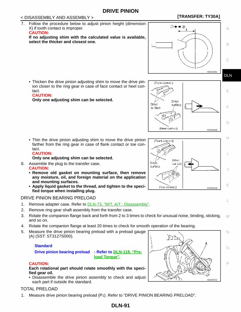
DRIVE PINION[TRANSFER: TY30A]
C
E
F
G
H
I
J
K
L
M
A
B
LN
N
O
P
< DISASSEMBLY AND ASSEMBLY >
D
7. Follow the procedure below to adjust pinion height (dimensionX) if tooth contact is improper.CAUTION:If no adjusting shim with the calculated value is available,select the thicker and closest one.
• Thicken the drive pinion adjusting shim to move the drive pin-ion closer to the ring gear in case of face contact or heel con-tact.CAUTION:Only one adjusting shim can be selected.
• Thin the drive pinion adjusting shim to move the drive pinionfarther from the ring gear in case of flank contact or toe con-tact.CAUTION:Only one adjusting shim can be selected.
8. Assemble the plug to the transfer case.CAUTION:• Remove old gasket on mounting surface, then remove
any moisture, oil, and foreign material on the applicationand mounting surfaces.
• Apply liquid gasket to the thread, and tighten to the speci-fied torque when installing plug.
DRIVE PINION BEARING PRELOAD1. Remove adapter case. Refer to DLN-73, "M/T, A/T : Disassembly".2. Remove ring gear shaft assembly from the transfer case.3. Rotate the companion flange back and forth from 2 to 3 times to check for unusual noise, binding, sticking,
and so on.4. Rotate the companion flange at least 20 times to check for smooth operation of the bearing.5. Measure the drive pinion bearing preload with a preload gauge
(A) (SST: ST3127S000).
CAUTION:Each rotational part should rotate smoothly with the speci-fied gear oil.• Disassemble the drive pinion assembly to check and adjust
each part if outside the standard.
TOTAL PRELOAD1. Measure drive pinion bearing preload (P1). Refer to “DRIVE PINION BEARING PRELOAD”.
SDIA3158J
PDIA0440E
PDIA0441E
StandardDrive pinion bearing preload : Refer to DLN-118, "Pre-
load Torque".
SDIA3072J
DLN-91

[TRANSFER: TY30A]DRIVE PINION
< DISASSEMBLY AND ASSEMBLY >CAUTION:Check that the drive pinion bearing preload is within the standard.
2. Assemble the ring gear shaft assembly to the transfer case.3. Install adapter case. Refer to DLN-73, "M/T, A/T : Assembly".4. Rotate the companion flange at least 20 times to check for smooth operation of the bearing.5. Measure the total preload with a preload gauge (A) (SST:
ST3127S000).
CAUTION:• Each rotational part should rotate smoothly with the spec-
ified gear oil.• Disassemble the transfer assembly to check and adjust each part if outside the standard. Mea-
sure it with the adapter case oil seals removed when measuring total preload after disassembly.Then install adapter case oil seals.
COMPANION FLANGE RUNOUT1. Fit a dial indicator onto the companion flange face (inner side of
the propeller shaft bolt holes).2. Rotate the companion flange to check for runout.
3. Fit a test indicator to the inner side of the companion flange(socket diameter).
4. Rotate the companion flange to check for runout.
5. Follow the procedure below to adjust if runout value is outsidethe repair limit.CAUTION:Replace collapsible spacer to check and adjust each partwhen companion flange is adjusted or replaced.
a. Check for runout while changing the phase between companion flange and drive pinion in 90° steps. Thensearch for the minimum point.
b. Replace companion flange if runout value is still outside the limit after the phase has been changed.c. Adjust assembly status of the drive pinion bearings and drive pinion, or replace drive pinion bearings if
runout is outside the standard after the companion flange is replaced.
ADJUSTING SHIM SELECTION
Measuring Point
StandardTotal preload
All oil seals are installed : Refer to DLN-118, "Preload Torque".
Without adapter case oil seal : Refer to DLN-118, "Preload Torque".
JSDIA0322ZZ
LimitCompanion flange runout : Refer to DLN-118, "Com-
panion Flange Runout".
SDIA3074J
LimitCompanion flange runout : Refer to DLN-118, "Com-
panion Flange Runout".
JSDIA0323ZZ
DLN-92

DRIVE PINION[TRANSFER: TY30A]
C
E
F
G
H
I
J
K
L
M
A
B
LN
N
O
P
< DISASSEMBLY AND ASSEMBLY >
D
Ring Gear Adjusting Shim (Adapter Case Side)
1. Measure the dimensions of each measuring point with the following procedure:
Dimension “A” measurement• Measure dimension from transfer case mounting surface of
adapter case to adapter case edge surface with a pair of ver-nier calipers and straightedge. Refer to “Measuring point”.
Dimension “B” measurement• Measure dimension from ring gear adjusting shim mounting
surface of adapter case to adapter case edge surface with apair of vernier calipers and straightedge. Refer to “Measuringpoint”.
Dimension “C” measurement
1. Adapter case 2. Ring gear shaft bearing(Adapter case side)
3. Ring gear shaft bearing(Transfer case side)
4. Ring gear shaft 5. Ring gear 6. Transfer case
JSDIA0256ZZ
SDIA3105J
JSDIA0324ZZ
DLN-93

[TRANSFER: TY30A]DRIVE PINION
< DISASSEMBLY AND ASSEMBLY >• Measure the diameter of drive pinion bearing (rear side)
mounting area of transfer case with a pair of vernier calipers.Refer to “Measuring point”.CAUTION:Never damage transfer case.
Dimension “D” measurement• Measure dimension from adapter case mounting surface of
transfer case to drive pinion bearing (rear side) mounting sur-face with a pair of vernier calipers and straightedge. Refer to“Measuring point”.CAUTION:• Never damage transfer case.• Consider the thickness of a straightedge.
Dimension “E” measurement• Measure dimension from outer race edge surface of ring gear
shaft bearing (adapter case side) to inner race edge surfacewith a pair of vernier calipers. Refer to “Measuring point”.
2. Calculate dimensions “M” and “N” by the formula below.
3. Convert the dimensions “E”, “M” and “N” according to the standards below.
SDIA3107J
SDIA3108J
SDIA3109J
Dimension “M” = “A” – “B”Dimension “N” = “C” × 0.5 mm (0.020 in) + “D”
“E” : Actual value regarding 20.00 mm (0.7874 in) as 0 in increments of 0.01 mm (0.0004 in).“M” : Actual value regarding 13.90 mm (0.5472 in) as 0 in increments of 0.01 mm (0.0004 in).“N” : Actual value regarding 55.00 mm (2.1654 in) as 0 in increments of 0.01 mm (0.0004 in).
DLN-94

DRIVE PINION[TRANSFER: TY30A]
C
E
F
G
H
I
J
K
L
M
A
B
LN
N
O
P
< DISASSEMBLY AND ASSEMBLY >
D
4. Check dimension “Z” (machining difference) on the ring gearback surface.NOTE:Dimension “Z” indicates difference between optimum engage-ment and the standard dimensions in increments of 0.01 mm(0.0004 in) written on the ring gear back surface.
5. Calculate the thickness of the ring gear adjusting shim (adaptercase side) “T1” by the formula below.
6. Select ring gear adjusting shim (adapter case side).CAUTION:• Only one adjusting shim can be selected.• Select the closest one, favoring thicker over thinner when necessary if no adjusting shim with
the calculated value is available.
Ring Gear Adjusting Shim (Transfer Case Side)
1. Measure the dimensions of each measuring point with the following procedure:
Dimension “C” measurement• Measure the diameter of drive pinion bearing (rear side)
mounting area of transfer case with a pair of vernier calipers.Refer to “Measuring point”.CAUTION:Never damage transfer case.
Dimension “D” measurement• Measure dimension from adapter case mounting surface of
transfer case to drive pinion bearing (rear side) mounting sur-face with a pair of vernier calipers and straightedge. Refer to“Measuring point”.CAUTION:• Never damage transfer case.• Consider the thickness of a straightedge.
Dimension “F” measurement• Measure dimension from adapter case mounting surface of
transfer case to ring gear adjusting shim mounting surfacewith a depth gauge. Refer to “Measuring point”.CAUTION:Never damage transfer case.
“T1” = (“M” + “N” – “E” – “Z”) × 0.01 mm (0.0004 in) + 1.40 mm (0.0551 in) SDIA3129J
SDIA3107J
SDIA3108J
SDIA3110J
DLN-95

[TRANSFER: TY30A]DRIVE PINION
< DISASSEMBLY AND ASSEMBLY >Dimension “G” measurement• Measure dimension from ring gear shaft bearing mounting sur-
face of ring gear to transfer case side edge surface with amicrometer and straightedge. Refer to “Measuring point”.CAUTION:Consider the thickness of a straightedge.
Dimension “H” measurement• Measure dimension from transfer case side edge surface of
ring gear to adapter case side edge surface with a pair of ver-nier calipers. Refer to “Measuring point”.
Dimension “I” measurement• Measure dimension from ring gear mounting surface of ring
gear shaft to ring gear shaft bearing (transfer case side)mounting surface with a pair of vernier calipers. Refer to “Mea-suring point”.
Dimension “J” measurement• Measure dimension from outer race edge surface of ring gear
shaft bearing (transfer case side) to inner race edge surfacewith a pair of vernier calipers. Refer to “Measuring point”.
2. Calculate dimension “N” by the formula below.
3. Convert the dimensions “F”, “G”, “H”, “I”, “J” and “N” according to the standards below.
SDIA3111J
SDIA3112J
JSDIA0257ZZ
SDIA3128J
Dimension “N” = “C” × 0.5 mm (0.020 in) + “D”
DLN-96
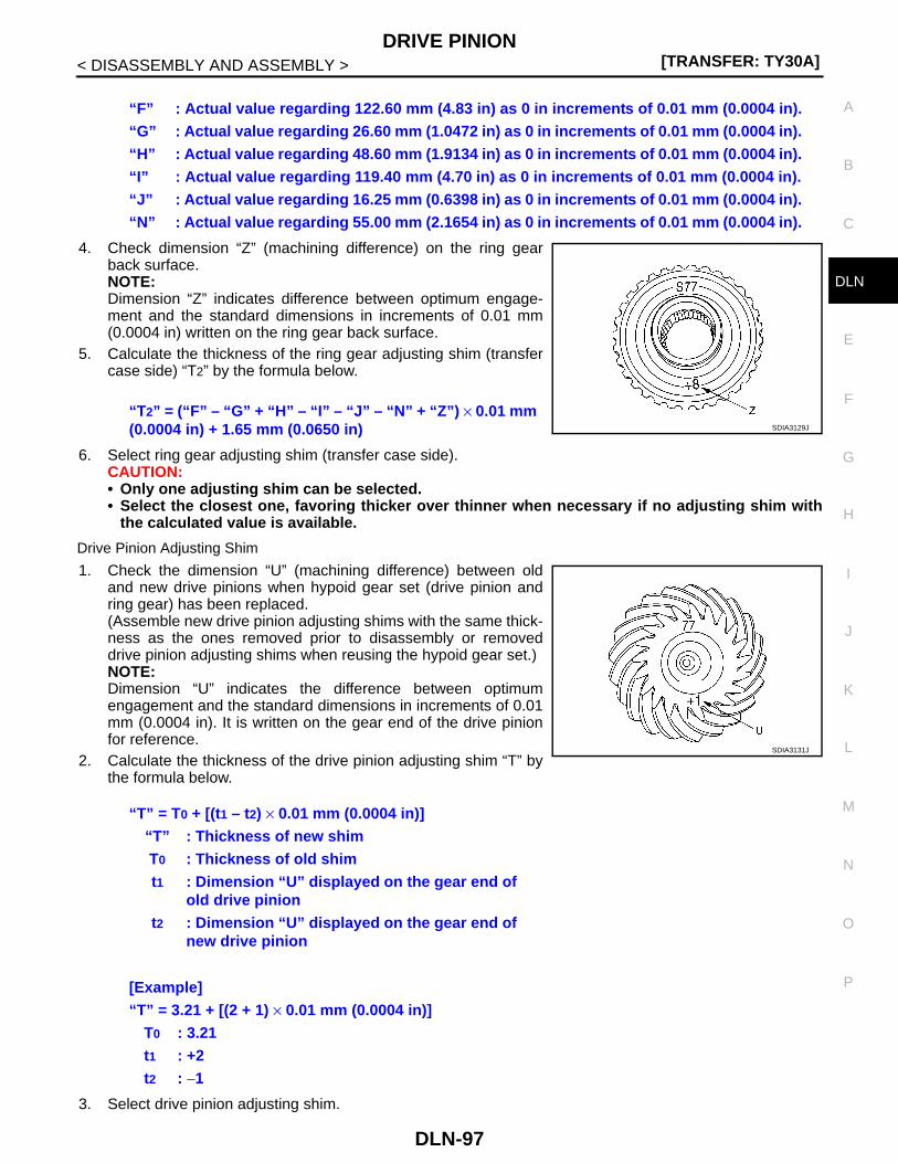
DRIVE PINION[TRANSFER: TY30A]
C
E
F
G
H
I
J
K
L
M
A
B
LN
N
O
P
< DISASSEMBLY AND ASSEMBLY >
D
4. Check dimension “Z” (machining difference) on the ring gearback surface.NOTE:Dimension “Z” indicates difference between optimum engage-ment and the standard dimensions in increments of 0.01 mm(0.0004 in) written on the ring gear back surface.
5. Calculate the thickness of the ring gear adjusting shim (transfercase side) “T2” by the formula below.
6. Select ring gear adjusting shim (transfer case side).CAUTION:• Only one adjusting shim can be selected.• Select the closest one, favoring thicker over thinner when necessary if no adjusting shim with
the calculated value is available.
Drive Pinion Adjusting Shim
1. Check the dimension “U” (machining difference) between oldand new drive pinions when hypoid gear set (drive pinion andring gear) has been replaced.(Assemble new drive pinion adjusting shims with the same thick-ness as the ones removed prior to disassembly or removeddrive pinion adjusting shims when reusing the hypoid gear set.)NOTE:Dimension “U” indicates the difference between optimumengagement and the standard dimensions in increments of 0.01mm (0.0004 in). It is written on the gear end of the drive pinionfor reference.
2. Calculate the thickness of the drive pinion adjusting shim “T” bythe formula below.
3. Select drive pinion adjusting shim.
“F” : Actual value regarding 122.60 mm (4.83 in) as 0 in increments of 0.01 mm (0.0004 in).“G” : Actual value regarding 26.60 mm (1.0472 in) as 0 in increments of 0.01 mm (0.0004 in).“H” : Actual value regarding 48.60 mm (1.9134 in) as 0 in increments of 0.01 mm (0.0004 in).“I” : Actual value regarding 119.40 mm (4.70 in) as 0 in increments of 0.01 mm (0.0004 in).“J” : Actual value regarding 16.25 mm (0.6398 in) as 0 in increments of 0.01 mm (0.0004 in).“N” : Actual value regarding 55.00 mm (2.1654 in) as 0 in increments of 0.01 mm (0.0004 in).
“T2” = (“F” – “G” + “H” – “I” – “J” – “N” + “Z”) × 0.01 mm (0.0004 in) + 1.65 mm (0.0650 in) SDIA3129J
“T” = T0 + [(t1 – t2) × 0.01 mm (0.0004 in)]“T” : Thickness of new shimT0 : Thickness of old shimt1 : Dimension “U” displayed on the gear end of
old drive piniont2 : Dimension “U” displayed on the gear end of
new drive pinion
[Example]“T” = 3.21 + [(2 + 1) × 0.01 mm (0.0004 in)]
T0 : 3.21t1 : +2t2 : −1
SDIA3131J
DLN-97

[TRANSFER: TY30A]DRIVE PINION
< DISASSEMBLY AND ASSEMBLY >CAUTION:• Only one adjusting shim can be selected.• Select the closest one, if no adjusting shim with the calculated value is available.
M/T, A/T : Inspection After Disassembly INFOID:0000000001278582
Check items below. If necessary, replace them with new ones.
GEAR AND SHAFTCheck gear face and shaft for wear, cracks, damage, and seizure.CAUTION:Replace ring gear and drive pinion as a set (hypoid gear set) if any malfunction is detected on the ringgear or drive pinion.
BEARINGCheck for seizure, peeling, wear, corrosion, sticking, unusual noise, roughness in hand turning, and otherdamage.CAUTION:Always replace inner race and outer race as a pair when replacing the bearing.
SHIMCheck for seizure, damage, and unusual wear.
CASECheck the bearing mounting surface for wear, cracks and damages.CVT
DLN-98

DRIVE PINION[TRANSFER: TY30A]
C
E
F
G
H
I
J
K
L
M
A
B
LN
N
O
P
< DISASSEMBLY AND ASSEMBLY >
D
CVT : Exploded View INFOID:0000000001349314
1. Adapter case oil seal 2. Adapter case 3. O-ring
4. Ring gear shaft 5. Ring gear adjusting shim(adapter case side)
6. Ring gear shaft bearing(adapter case side)
7. Ring gear 8. Ring gear nut 9. Ring gear shaft bearing(transfer case side)
10. Ring gear adjusting shim(transfer case side)
11. Transfer case 12. Air breather hose
13. Air breather tube 14. Gasket 15. Filler plug
16. Drain plug 17. Plug 18. Drive pinion
19. Drive pinion adjusting shim 20. Drive pinion bearing (front side) 21. Collapsible spacer
22. Drive pinion bearing (rear side) 23. Drive pinion oil seal 24. Companion flange
25. Lock nut
A: Oil seal lip
: Apply gear oil.
: Apply multi-purpose grease.
: Apply anti-corrosive oil.
JSDIA0320GB
DLN-99
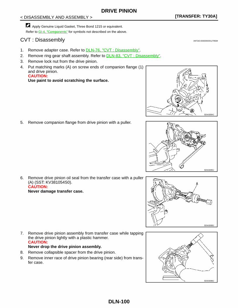
[TRANSFER: TY30A]DRIVE PINION
< DISASSEMBLY AND ASSEMBLY >
CVT : Disassembly INFOID:0000000001278584
1. Remove adapter case. Refer to DLN-76, "CVT : Disassembly".2. Remove ring gear shaft assembly. Refer to DLN-83, "CVT : Disassembly".3. Remove lock nut from the drive pinion.4. Put matching marks (A) on screw ends of companion flange (1)
and drive pinion.CAUTION:Use paint to avoid scratching the surface.
5. Remove companion flange from drive pinion with a puller.
6. Remove drive pinion oil seal from the transfer case with a puller(A) (SST: KV381054S0).CAUTION:Never damage transfer case.
7. Remove drive pinion assembly from transfer case while tappingthe drive pinion lightly with a plastic hammer.CAUTION:Never drop the drive pinion assembly.
8. Remove collapsible spacer from the drive pinion.9. Remove inner race of drive pinion bearing (rear side) from trans-
fer case.
: Apply Genuine Liquid Gasket, Three Bond 1215 or equivalent.
Refer to GI-4, "Components" for symbols not described on the above.
SDIA3084J
SDIA3085J
SDIA3089J
SDIA3086J
DLN-100

DRIVE PINION[TRANSFER: TY30A]
C
E
F
G
H
I
J
K
L
M
A
B
LN
N
O
P
< DISASSEMBLY AND ASSEMBLY >
D
10. Remove inner race of drive pinion bearing (front side) from drivepinion with a drift (A) (SST: ST33052000) and replacer (B) (SST:ST22730000).
11. Remove drive pinion adjusting shim from the drive pinion.
CVT : Assembly INFOID:0000000001278585
1. Select drive pinion adjusting shim. Refer to DLN-102, "CVT : Adjustment".2. Install selected drive pinion adjusting shim to drive pinion.3. Install inner race of drive pinion bearing (front side) to drive pin-
ion with a drift (A) (SST: ST23860000).CAUTION:• Never reuse drive pinion bearing (front side).• Apply gear oil to the drive pinion bearing (front side).
4. Assemble the inner race of drive pinion bearing (rear side) intothe transfer case.CAUTION:• Never reuse drive pinion bearing (rear side).• Apply gear oil to the drive pinion bearing (rear side).
5. Install drive pinion oil seal to transfer case with drifts so that itbecomes flush with case end surface.
CAUTION:• Never reuse oil seal.• Apply multi-purpose grease onto oil seal lips, and gear oil
onto the circumference.6. Assemble a collapsible spacer onto the drive pinion.
CAUTION:Never reuse the collapsible spacer.
7. Assemble drive pinion assembly into the transfer case, and theninstall companion flange (1) to drive pinion.NOTE:Align matching marks (A) on the thread edge of companionflange and drive pinion and install companion flange if drive pin-ion is reused.
SDIA3087J
SDIA3094J
A : Drift (SST: ST27861000)
B : Drift (SST: ST30720000)
SDIA3093J
SDIA3084J
DLN-101

[TRANSFER: TY30A]DRIVE PINION
< DISASSEMBLY AND ASSEMBLY >8. Tap the companion flange with a plastic hammer as far as the
lock nut can be tightened.CAUTION:Never damage drive pinion oil seal.
9. Apply anti-corrosive oil to the thread and seat of the lock nut,and temporarily tighten lock nut to the drive pinion.CAUTION:Never reuse lock nut.
10. Tighten lock nut within the specified torque range with a preloadgauge (A) (SST: ST3127S000) so that the drive pinion bearingpreload is within standard.
CAUTION:• Start the tightening of lock nut from lower limit of the
specified torque. Check the preload every 5° to 10° whiletightening the lock nut.
• Replace the collapsible spacer and tighten it again to adjust if preload exceeds the specifiedvalue. Never loosen lock nut to adjust preload.
• After adjustment, rotate the drive pinion back and forth from 2 to 3 times to check for unusualnoise, sticking, binding, and so on.
11. Install ring gear shaft assembly. Refer to DLN-84, "CVT : Assembly".12. Install adapter case. Refer to DLN-76, "CVT : Assembly".13. Check backlash, tooth contact, total preload and companion flange runout. Refer to DLN-102, "CVT :
Adjustment".CAUTION:Measure the total preload without the adapter case oil seal.
CVT : Adjustment INFOID:0000000001278586
BACKLASH1. Install the bolt (A) to the companion flange.2. Fit a dial indicator onto the bolt.3. Measure the circumference backlash of the companion flange.
Disassemble the transfer assembly to check and adjust eachpart if outside the standard.
TOOTH CONTACT1. Remove adapter case. Refer to DLN-76, "CVT : Disassembly".
SDIA3095J
StandardDrive pinion bearing preload : Refer to DLN-118, "Pre-
load Torque".
SDIA3072J
StandardBacklash : Refer to DLN-118, "Backlash".
SDIA3065J
DLN-102
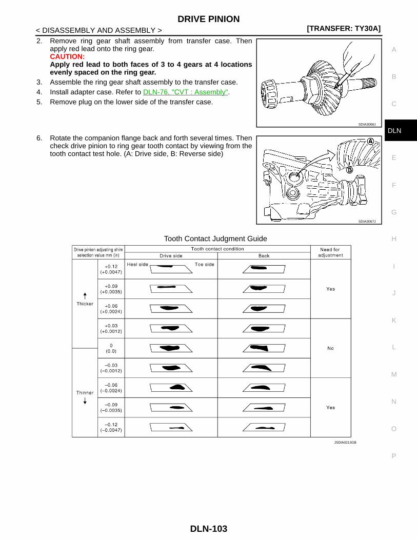
DRIVE PINION[TRANSFER: TY30A]
C
E
F
G
H
I
J
K
L
M
A
B
LN
N
O
P
< DISASSEMBLY AND ASSEMBLY >
D
2. Remove ring gear shaft assembly from transfer case. Thenapply red lead onto the ring gear.CAUTION:Apply red lead to both faces of 3 to 4 gears at 4 locationsevenly spaced on the ring gear.
3. Assemble the ring gear shaft assembly to the transfer case.4. Install adapter case. Refer to DLN-76, "CVT : Assembly".5. Remove plug on the lower side of the transfer case.
6. Rotate the companion flange back and forth several times. Thencheck drive pinion to ring gear tooth contact by viewing from thetooth contact test hole. (A: Drive side, B: Reverse side)
Tooth Contact Judgment Guide
SDIA3066J
SDIA3067J
JSDIA0213GB
DLN-103

[TRANSFER: TY30A]DRIVE PINION
< DISASSEMBLY AND ASSEMBLY >7. Follow the procedure below to adjust pinion height (dimension
X) if tooth contact is improper.CAUTION:If no adjusting shim with the calculated value is available,select the thicker and closest one.
• Thicken the drive pinion adjusting shim to move the drive pin-ion closer to the ring gear in case of face contact or heel con-tact.CAUTION:Only one adjusting shim can be selected.
• Thin the drive pinion adjusting shim to move the drive pinionfarther from the ring gear in case of flank contact or toe con-tact.CAUTION:Only one adjusting shim can be selected.
8. Assemble the plug to the transfer case.CAUTION:• Remove old gasket on mounting surface, then remove
any moisture, oil, and foreign material on the applicationand mounting surfaces.
• Apply liquid gasket to the thread, and tighten to the speci-fied torque when installing plug.
DRIVE PINION BEARING PRELOAD1. Remove adapter case. Refer to DLN-76, "CVT : Disassembly".2. Remove ring gear shaft assembly from the transfer case.3. Rotate the companion flange back and forth from 2 to 3 times to check for unusual noise, binding, sticking,
and so on.4. Rotate the companion flange at least 20 times to check for smooth operation of the bearing.5. Measure the drive pinion bearing preload with a preload gauge
(A) (SST: ST3127S000).
CAUTION:Each rotational part should rotate smoothly with the speci-fied gear oil.• Disassemble the drive pinion assembly to check and adjust
each part if outside the standard.
TOTAL PRELOAD1. Measure drive pinion bearing preload (P1). Refer to “DRIVE PINION BEARING PRELOAD”.
SDIA3158J
PDIA0440E
PDIA0441E
StandardDrive pinion bearing preload : Refer to DLN-118, "Pre-
load Torque".
SDIA3072J
DLN-104

DRIVE PINION[TRANSFER: TY30A]
C
E
F
G
H
I
J
K
L
M
A
B
LN
N
O
P
< DISASSEMBLY AND ASSEMBLY >
D
CAUTION:Check that the drive pinion bearing preload is within the standard.
2. Assemble the ring gear shaft assembly to the transfer case.3. Install adapter case. Refer to DLN-76, "CVT : Assembly".4. Rotate the companion flange at least 20 times to check for smooth operation of the bearing.5. Measure the total preload with a preload gauge (A) (SST:
ST3127S000).
CAUTION:• Each rotational part should rotate smoothly with the spec-
ified gear oil.• Disassemble the transfer assembly to check and adjust each part if outside the standard. Mea-
sure it with the adapter case oil seals removed when measuring total preload after disassembly.Then install adapter case oil seals.
COMPANION FLANGE RUNOUT1. Fit a dial indicator onto the companion flange face (inner side of
the propeller shaft bolt holes).2. Rotate the companion flange to check for runout.
3. Fit a test indicator to the inner side of the companion flange(socket diameter).
4. Rotate the companion flange to check for runout.
5. Follow the procedure below to adjust if runout value is outsidethe repair limit.CAUTION:Replace collapsible spacer to check and adjust each partwhen companion flange is adjusted or replaced.
a. Check for runout while changing the phase between companion flange and drive pinion in 90° steps. Thensearch for the minimum point.
b. Replace companion flange if runout value is still outside the limit after the phase has been changed.c. Adjust assembly status of the drive pinion bearings and drive pinion, or replace drive pinion bearings if
runout is outside the standard after the companion flange is replaced.
ADJUSTING SHIM SELECTION
Measuring Point
StandardTotal preload
All oil seals are installed : Refer to DLN-118, "Preload Torque".
Without adapter case oil seal : Refer to DLN-118, "Preload Torque".
SDIA3073J
LimitCompanion flange runout : Refer to DLN-118, "Com-
panion Flange Runout".
SDIA3074J
LimitCompanion flange runout : Refer to DLN-118, "Com-
panion Flange Runout".
SDIA3075J
DLN-105

[TRANSFER: TY30A]DRIVE PINION
< DISASSEMBLY AND ASSEMBLY >
Ring Gear Adjusting Shim (Adapter Case Side)
1. Measure the dimensions of each measuring point with the following procedure:
Dimension “A” measurement• Measure dimension from transfer case mounting surface of
adapter case to adapter case edge surface with a pair of ver-nier calipers and straightedge. Refer to “Measuring point”.
Dimension “B” measurement• Measure dimension from ring gear adjusting shim mounting
surface of adapter case to adapter case edge surface with apair of vernier calipers and straightedge. Refer to “Measuringpoint”.
Dimension “C” measurement
1. Adapter case 2. Ring gear shaft bearing(Adapter case side)
3. Ring gear shaft bearing(Transfer case side)
4. Ring gear shaft 5. Ring gear 6. Transfer case
JSDIA0263ZZ
SDIA3105J
JSDIA0324ZZ
DLN-106

DRIVE PINION[TRANSFER: TY30A]
C
E
F
G
H
I
J
K
L
M
A
B
LN
N
O
P
< DISASSEMBLY AND ASSEMBLY >
D
• Measure the diameter of drive pinion bearing (rear side)mounting area of transfer case with a pair of vernier calipers.Refer to “Measuring point”.CAUTION:Never damage transfer case.
Dimension “D” measurement• Measure dimension from adapter case mounting surface of
transfer case to drive pinion bearing (rear side) mounting sur-face with a pair of vernier calipers and straightedge. Refer to“Measuring point”.CAUTION:• Never damage transfer case.• Consider the thickness of a straightedge.
Dimension “E” measurement• Measure dimension from outer race edge surface of ring gear
shaft bearing (adapter case side) to inner race edge surfacewith a pair of vernier calipers. Refer to “Measuring point”.
2. Calculate dimensions “M” and “N” by the formula below.
3. Convert the dimensions “E”, “M” and “N” according to the standards below.
SDIA3107J
SDIA3108J
SDIA3109J
Dimension “M” = “A” – “B”Dimension “N” = “C” × 0.5 mm (0.020 in) + “D”
“E” : Actual value regarding 20.00 mm (0.7874 in) as 0 in increments of 0.01 mm (0.0004 in).“M” : Actual value regarding 13.90 mm (0.5472 in) as 0 in increments of 0.01 mm (0.0004 in).“N” : Actual value regarding 55.00 mm (2.1654 in) as 0 in increments of 0.01 mm (0.0004 in).
DLN-107

[TRANSFER: TY30A]DRIVE PINION
< DISASSEMBLY AND ASSEMBLY >4. Check dimension “Z” (machining difference) on the ring gear
back surface.NOTE:Dimension “Z” indicates difference between optimum engage-ment and the standard dimensions in increments of 0.01 mm(0.0004 in) written on the ring gear back surface.
5. Calculate the thickness of the ring gear adjusting shim (adaptercase side) “T1” by the formula below.
6. Select ring gear adjusting shim (adapter case side).CAUTION:• Only one adjusting shim can be selected.• Select the closest one, favoring thicker over thinner when necessary if no adjusting shim with
the calculated value is available.
Ring Gear Adjusting Shim (Transfer Case Side)
1. Measure the dimensions of each measuring point with the following procedure:
Dimension “C” measurement• Measure the diameter of drive pinion bearing (rear side)
mounting area of transfer case with a pair of vernier calipers.Refer to “Measuring point”.CAUTION:Never damage transfer case.
Dimension “D” measurement• Measure dimension from adapter case mounting surface of
transfer case to drive pinion bearing (rear side) mounting sur-face with a pair of vernier calipers and straightedge. Refer to“Measuring point”.CAUTION:• Never damage transfer case.• Consider the thickness of a straightedge.
Dimension “F” measurement• Measure dimension from adapter case mounting surface of
transfer case to ring gear adjusting shim mounting surfacewith a depth gauge. Refer to “Measuring point”.CAUTION:Never damage transfer case.
“T1” = (“M” + “N” – “E” – “Z”) × 0.01 mm (0.0004 in) + 1.40 mm (0.0551 in) SDIA3129J
SDIA3107J
SDIA3108J
SDIA3110J
DLN-108

DRIVE PINION[TRANSFER: TY30A]
C
E
F
G
H
I
J
K
L
M
A
B
LN
N
O
P
< DISASSEMBLY AND ASSEMBLY >
D
Dimension “G” measurement• Measure dimension from ring gear shaft bearing mounting sur-
face of ring gear to transfer case side edge surface with amicrometer and straightedge. Refer to “Measuring point”.CAUTION:Consider the thickness of a straightedge.
Dimension “H” measurement• Measure dimension from transfer case side edge surface of
ring gear to adapter case side edge surface with a pair of ver-nier calipers. Refer to “Measuring point”.
Dimension “I” measurement• Measure dimension from ring gear mounting surface of ring
gear shaft to ring gear shaft bearing (transfer case side)mounting surface with a pair of vernier calipers. Refer to “Mea-suring point”.
Dimension “J” measurement• Measure dimension from outer race edge surface of ring gear
shaft bearing (transfer case side) to inner race edge surfacewith a pair of vernier calipers. Refer to “Measuring point”.
2. Calculate dimension “N” by the formula below.
3. Convert the dimensions “F”, “G”, “H”, “I”, “J” and “N” according to the standards below.
SDIA3111J
SDIA3112J
SDIA3113J
SDIA3128J
Dimension “N” = “C” × 0.5 mm (0.020 in) + “D”
DLN-109
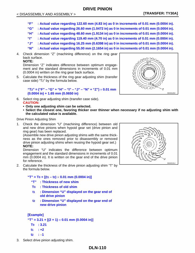
[TRANSFER: TY30A]DRIVE PINION
< DISASSEMBLY AND ASSEMBLY >
4. Check dimension “Z” (machining difference) on the ring gearback surface.NOTE:Dimension “Z” indicates difference between optimum engage-ment and the standard dimensions in increments of 0.01 mm(0.0004 in) written on the ring gear back surface.
5. Calculate the thickness of the ring gear adjusting shim (transfercase side) “T2” by the formula below.
6. Select ring gear adjusting shim (transfer case side).CAUTION:• Only one adjusting shim can be selected.• Select the closest one, favoring thicker over thinner when necessary if no adjusting shim with
the calculated value is available.
Drive Pinion Adjusting Shim
1. Check the dimension “U” (machining difference) between oldand new drive pinions when hypoid gear set (drive pinion andring gear) has been replaced.(Assemble new drive pinion adjusting shims with the same thick-ness as the ones removed prior to disassembly or removeddrive pinion adjusting shims when reusing the hypoid gear set.)NOTE:Dimension “U” indicates the difference between optimumengagement and the standard dimensions in increments of 0.01mm (0.0004 in). It is written on the gear end of the drive pinionfor reference.
2. Calculate the thickness of the drive pinion adjusting shim “T” bythe formula below.
3. Select drive pinion adjusting shim.
“F” : Actual value regarding 122.60 mm (4.83 in) as 0 in increments of 0.01 mm (0.0004 in).“G” : Actual value regarding 26.60 mm (1.0472 in) as 0 in increments of 0.01 mm (0.0004 in).“H” : Actual value regarding 48.60 mm (1.9134 in) as 0 in increments of 0.01 mm (0.0004 in).“I” : Actual value regarding 119.40 mm (4.70 in) as 0 in increments of 0.01 mm (0.0004 in).“J” : Actual value regarding 16.25 mm (0.6398 in) as 0 in increments of 0.01 mm (0.0004 in).“N” : Actual value regarding 55.00 mm (2.1654 in) as 0 in increments of 0.01 mm (0.0004 in).
“T2” = (“F” – “G” + “H” – “I” – “J” – “N” + “Z”) × 0.01 mm (0.0004 in) + 1.65 mm (0.0650 in) SDIA3129J
“T” = T0 + [(t1 – t2) × 0.01 mm (0.0004 in)]“T” : Thickness of new shimT0 : Thickness of old shimt1 : Dimension “U” displayed on the gear end of
old drive piniont2 : Dimension “U” displayed on the gear end of
new drive pinion
[Example]“T” = 3.21 + [(2 + 1) × 0.01 mm (0.0004 in)]
T0 : 3.21t1 : +2t2 : −1
SDIA3131J
DLN-110

DRIVE PINION[TRANSFER: TY30A]
C
E
F
G
H
I
J
K
L
M
A
B
LN
N
O
P
< DISASSEMBLY AND ASSEMBLY >
D
CAUTION:• Only one adjusting shim can be selected.• Select the closest one, if no adjusting shim with the calculated value is available.
CVT : Inspection After Disassembly INFOID:0000000001278587
Check items below. If necessary, replace them with new ones.
GEAR AND SHAFTCheck gear face and shaft for wear, cracks, damage, and seizure.CAUTION:Replace ring gear and drive pinion as a set (hypoid gear set) if any malfunction is detected on the ringgear or drive pinion.
BEARINGCheck for seizure, peeling, wear, corrosion, sticking, unusual noise, roughness in hand turning, and otherdamage.CAUTION:Always replace inner race and outer race as a pair when replacing the bearing.
SHIMCheck for seizure, damage, and unusual wear.
CASECheck the bearing mounting surface for wear, cracks and damages.
DLN-111
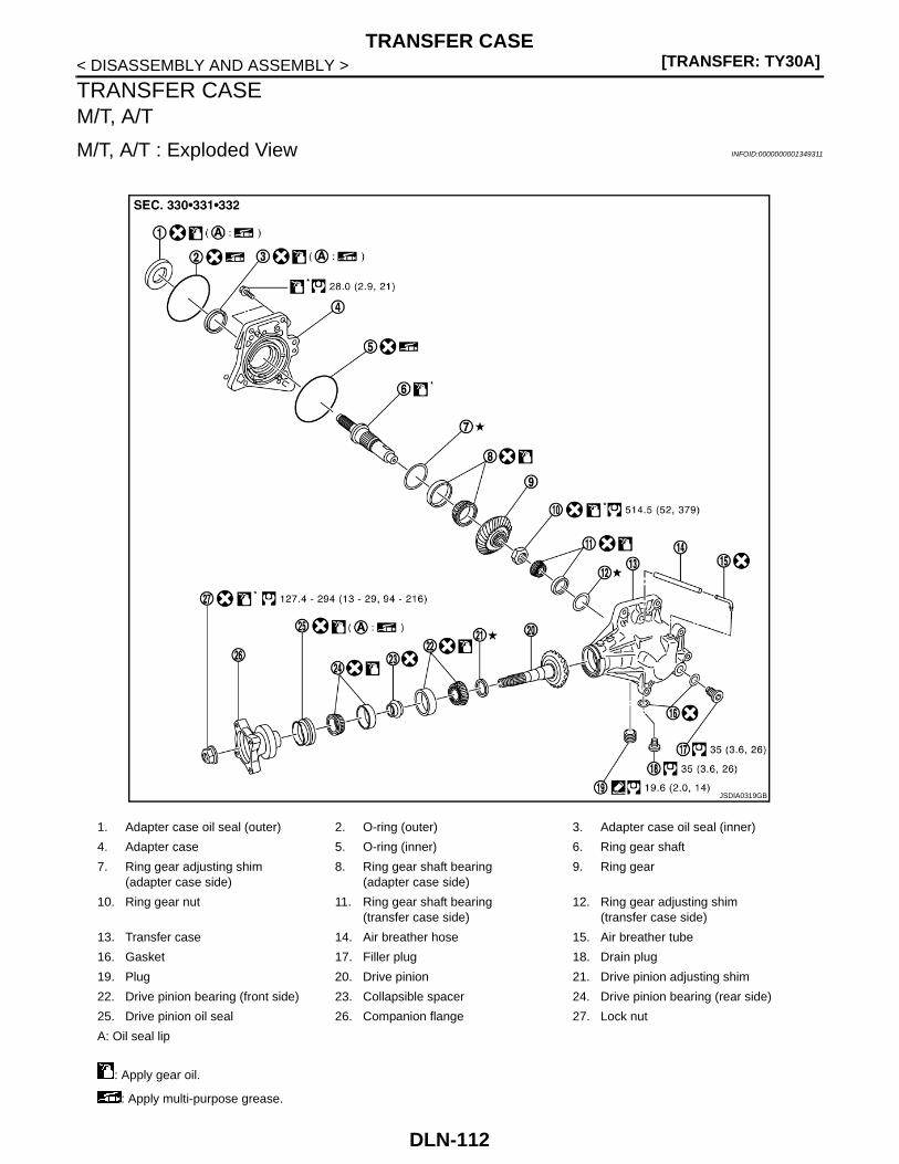
[TRANSFER: TY30A]TRANSFER CASE
< DISASSEMBLY AND ASSEMBLY >
TRANSFER CASEM/T, A/T
M/T, A/T : Exploded View INFOID:0000000001349311
1. Adapter case oil seal (outer) 2. O-ring (outer) 3. Adapter case oil seal (inner)
4. Adapter case 5. O-ring (inner) 6. Ring gear shaft
7. Ring gear adjusting shim(adapter case side)
8. Ring gear shaft bearing(adapter case side)
9. Ring gear
10. Ring gear nut 11. Ring gear shaft bearing(transfer case side)
12. Ring gear adjusting shim(transfer case side)
13. Transfer case 14. Air breather hose 15. Air breather tube
16. Gasket 17. Filler plug 18. Drain plug
19. Plug 20. Drive pinion 21. Drive pinion adjusting shim
22. Drive pinion bearing (front side) 23. Collapsible spacer 24. Drive pinion bearing (rear side)
25. Drive pinion oil seal 26. Companion flange 27. Lock nut
A: Oil seal lip
: Apply gear oil.
: Apply multi-purpose grease.
JSDIA0319GB
DLN-112

TRANSFER CASE[TRANSFER: TY30A]
C
E
F
G
H
I
J
K
L
M
A
B
LN
N
O
P
< DISASSEMBLY AND ASSEMBLY >
D
M/T, A/T : Disassembly INFOID:0000000001278589
1. Remove adapter case. Refer to DLN-73, "M/T, A/T : Disassembly".2. Remove ring gear shaft assembly. Refer to DLN-79, "M/T, A/T : Disassembly".3. Remove drive pinion assembly. Refer to DLN-87, "M/T, A/T : Disassembly".4. Tap the outer race of drive pinion bearing from transfer case with
a brass rod to remove outer race of drive pinion bearing (frontside and rear side).CAUTION:Never damage transfer case.
5. Remove air breather hose from transfer case.CAUTION:Never damage air breather hose.
6. Remove air breather tube from transfer case.7. Remove the filler plug and drain plug from the transfer case, and
then remove each gasket.8. Remove plug from transfer case.
M/T, A/T : Assembly INFOID:0000000001278590
1. Install outer race of drive pinion bearing (front side) to the trans-fer case with drifts and bushing remover.
CAUTION:• Never reuse drive pinion bearing (front side).• Apply gear oil to the drive pinion bearing (front side)
2. Install outer race of drive pinion bearing (rear side) to transfercase with a drift (A) (SST: ST33230000).CAUTION:• Never reuse drive pinion bearing (rear side).• Apply gear oil to the drive pinion bearing (rear side).
3. Install drive pinion assembly. Refer to DLN-88, "M/T, A/T :Assembly".
4. Install ring gear shaft assembly. Refer to DLN-80, "M/T, A/T :Assembly".
5. Install adapter case. Refer to DLN-73, "M/T, A/T : Assembly".
: Apply anti-corrosive oil.
: Apply Genuine Liquid Gasket, Three Bond 1215 or equivalent.
Refer to GI-4, "Components" for symbols not described on the above.
SDIA3088J
A : Drift (commercial service tool)
B : Drift (SST: ST35272000)
C : Bushing remover (SST: ST38280000)
SDIA3091J
SDIA3092J
DLN-113

[TRANSFER: TY30A]TRANSFER CASE
< DISASSEMBLY AND ASSEMBLY >6. Install the air breather tube to the transfer case with its opening
facing (A) rearward from transfer input shaft direction (B).
CAUTION:Never reuse air breather tube.
7. Install air breather hose.CAUTION:• Never damage air breather hose.• Face the paint area (A) in the direction shown in the fig-
ure.
8. Check backlash, tooth contact, total preload and companion flange runout. Refer to DLN-89, "M/T, A/T :Adjustment".CAUTION:Measure the total preload without the adapter case oil seals.
9. Assemble the plug to the transfer case.CAUTION:• Remove old gasket on mounting surface, then remove any moisture, oil, and foreign material on
the application and mounting surfaces.• Apply liquid gasket to the threads of plug.
10. Install gaskets onto filler plug and drain plug and install them into transfer case.CAUTION:• Never reuse gaskets.• Install filler plug after oil is filled.
M/T, A/T : Inspection INFOID:0000000001278591
Check items below. If necessary, replace them with new ones.
CASECheck the bearing mounting surface for wear, cracks and damages.CVT
Angle “A” : 25° – 45 °
SDIA3090J
JSDIA0325ZZ
DLN-114

TRANSFER CASE[TRANSFER: TY30A]
C
E
F
G
H
I
J
K
L
M
A
B
LN
N
O
P
< DISASSEMBLY AND ASSEMBLY >
D
CVT : Exploded View INFOID:0000000001349315
1. Adapter case oil seal 2. Adapter case 3. O-ring
4. Ring gear shaft 5. Ring gear adjusting shim(adapter case side)
6. Ring gear shaft bearing(adapter case side)
7. Ring gear 8. Ring gear nut 9. Ring gear shaft bearing(transfer case side)
10. Ring gear adjusting shim(transfer case side)
11. Transfer case 12. Air breather hose
13. Air breather tube 14. Gasket 15. Filler plug
16. Drain plug 17. Plug 18. Drive pinion
19. Drive pinion adjusting shim 20. Drive pinion bearing (front side) 21. Collapsible spacer
22. Drive pinion bearing (rear side) 23. Drive pinion oil seal 24. Companion flange
25. Lock nut
A: Oil seal lip
: Apply gear oil.
: Apply multi-purpose grease.
: Apply anti-corrosive oil.
JSDIA0320GB
DLN-115

[TRANSFER: TY30A]TRANSFER CASE
< DISASSEMBLY AND ASSEMBLY >
CVT : Disassembly INFOID:0000000001278593
1. Remove adapter case. Refer to DLN-76, "CVT : Disassembly".2. Remove ring gear shaft assembly. Refer to DLN-83, "CVT : Disassembly".3. Remove drive pinion assembly. Refer to DLN-100, "CVT : Disassembly".4. Tap the outer race of drive pinion bearing from transfer case with
a brass rod to remove outer race of drive pinion bearing (frontside and rear side).CAUTION:Never damage transfer case.
5. Remove air breather hose from transfer case.CAUTION:Never damage air breather hose.
6. Remove air breather tube from transfer case.7. Remove the filler plug and drain plug from the transfer case, and
then remove each gasket.8. Remove plug from transfer case.
CVT : Assembly INFOID:0000000001278594
1. Install outer race of drive pinion bearing (front side) to the trans-fer case with drifts and bushing remover.
CAUTION:• Never reuse drive pinion bearing (front side).• Apply gear oil to the drive pinion bearing (front side)
2. Install outer race of drive pinion bearing (rear side) to transfercase with a drift (A) (SST: ST33230000).CAUTION:• Never reuse drive pinion bearing (rear side).• Apply gear oil to the drive pinion bearing (rear side).
3. Install drive pinion assembly. Refer to DLN-101, "CVT : Assem-bly".
4. Install ring gear shaft assembly. Refer to DLN-84, "CVT :Assembly".
5. Install adapter case. Refer to DLN-76, "CVT : Assembly".
: Apply Genuine Liquid Gasket, Three Bond 1215 or equivalent.
Refer to GI-4, "Components" for symbols not described on the above.
SDIA3088J
A : Drift (SST: ST30621000)
B : Drift (SST: ST35272000)
C : Bushing remover (SST: ST38280000)
SDIA3091J
SDIA3092J
DLN-116

TRANSFER CASE[TRANSFER: TY30A]
C
E
F
G
H
I
J
K
L
M
A
B
LN
N
O
P
< DISASSEMBLY AND ASSEMBLY >
D
6. Install the air breather tube to the transfer case with its openingfacing (A) rearward from transfer input shaft direction (B).
CAUTION:Never reuse air breather tube.
7. Install air breather hose.CAUTION:• Never damage air breather hose.• Face the paint area (A) in the direction shown in the fig-
ure.
8. Check backlash, tooth contact, total preload and companion flange runout. Refer to DLN-102, "CVT :Adjustment".CAUTION:Measure the total preload without the adapter case oil seals.
9. Assemble the plug to the transfer case.CAUTION:• Remove old gasket on mounting surface, then remove any moisture, oil, and foreign material on
the application and mounting surfaces.• Apply liquid gasket to the threads of plug.
10. Install gaskets onto filler plug and drain plug and install them into transfer case.CAUTION:• Never reuse gaskets.• Install filler plug after oil is filled.
CVT : Inspection INFOID:0000000001278595
Check items below. If necessary, replace them with new ones.
CASECheck the bearing mounting surface for wear, cracks and damages.
Angle “A” : 25° – 35 °
SDIA3090J
JSDIA0325ZZ
DLN-117

[TRANSFER: TY30A]SERVICE DATA AND SPECIFICATIONS (SDS)
< SERVICE DATA AND SPECIFICATIONS (SDS)
SERVICE DATA AND SPECIFICATIONS (SDS)SERVICE DATA AND SPECIFICATIONS (SDS)
General Specifications INFOID:0000000001278596
Preload Torque INFOID:0000000001278597
Unit: N·m (kg-m, in-lb)
Backlash INFOID:0000000001278598
Unit: mm (in)
Companion Flange Runout INFOID:0000000001278599
Unit: mm (in)
Applied model
4WD
MR20DE, QR25DE M9R
M/T CVT M/T A/T
Transfer model TY30A
Oil capacity (Approx.) (lmp pt) 0.38 (5/8) 0.36 (5/8) 0.38 (5/8)
Gear ratio 0.656
Number of teethDrive pinion 32
Drive gear 21
ItemStandard
M/T, A/T CVT
Drive pinion bearing preload (P1) 0.52 – 1.01 (0.06 – 0.10, 5 – 8)
Total preloadWith all oil seals
P1 + 0.76 – 0.96 (0.08 – 0.09, 7 – 8)
P1 + 0.71 – 0.91 (0.08 – 0.09, 7 – 8)
Without adapter case oil seal P1 + 0.55 – 0.75 (0.06 – 0.07, 5 – 6)
Item Standard
Ring gear to drive pinion 0.13 – 0.19 (0.0051 – 0.0075)
Item Limit
Companion flange face (inner side of the propeller shaft bolt holes) 0.1 (0.004)
Inside of companion flange (socket diameter) 0.1 (0.004)
DLN-118

NOISE, VIBRATION AND HARSHNESS (NVH) TROUBLESHOOTING[REAR PROPELLER SHAFT: 3F SPL18-DOJ75]
C
E
F
G
H
I
J
K
L
M
A
B
LN
N
O
P
< SYMPTOM DIAGNOSIS >
D
SYMPTOM DIAGNOSISNOISE, VIBRATION AND HARSHNESS (NVH) TROUBLESHOOTING
NVH Troubleshooting Chart INFOID:0000000001220282
Use the chart below to help you find the cause of the symptom. If necessary, repair or replace these parts.
×: Applicable
Reference
DLN
-120
, "In
spec
tion"
DLN
-123
, "In
spec
tion" —
DLN
-123
, "In
spec
tion" —
DLN
-123
, "In
spec
tion"
DLN
-120
, "In
spec
tion"
NV
H in
DLN
sec
tion
NV
H in
FA
X, R
AX
, FS
U a
nd R
SU
sec
tion
NV
H in
WT
sec
tion
NV
H in
WT
sec
tion
NV
H in
FA
X a
nd R
AX
sec
tion
NV
H in
BR
sec
tion
NV
H in
ST
sec
tion
Possible cause and SUSPECTED PARTS
Une
ven
rota
ting
torq
ue
Cen
ter
bear
ing
impr
oper
inst
alla
tion
Exc
essi
ve c
ente
r be
arin
g ax
ial e
nd p
lay
Cen
ter
bear
ing
mou
ntin
g (in
sula
tor)
cra
cks,
dam
age
or d
eter
iora
tion
Exc
essi
ve jo
int a
ngle
Rot
atio
n im
bala
nce
Exc
essi
ve r
unou
t
DIF
FE
RE
NT
IAL
AX
LE A
ND
SU
SP
EN
SIO
N
TIR
E
RO
AD
WH
EE
L
DR
IVE
SH
AF
T
BR
AK
E
ST
EE
RIN
G
Symptom
Noise × × × × × × × × × × × × × ×
Shake × × × × × × × ×
Vibration × × × × × × × × × × ×
DLN-119

[REAR PROPELLER SHAFT: 3F SPL18-DOJ75]REAR PROPELLER SHAFT
< ON-VEHICLE MAINTENANCE >
ON-VEHICLE MAINTENANCEREAR PROPELLER SHAFT
Inspection INFOID:0000000001220283
NOISE• Check the propeller shaft tube surface for dents or cracks. If damaged, replace propeller shaft assembly.• If center bearing is noisy or damaged, replace propeller shaft assembly.
VIBRATIONIf vibration is present at high speed, inspect propeller shaft runout first.1. Measure propeller shaft runout at runout measuring points by
rotating final drive companion flange with hands.
2. If runout still exceeds specifications, separate propeller shaft atfinal drive companion flange or transfer companion flange; thenrotate companion flange 90, 180, 270 degrees and install pro-peller shaft.
3. Check runout again. If runout still exceeds specifications,replace propeller shaft assembly.
4. Check the vibration by driving vehicle.
RUNOUT MEASURING POINTPropeller shaft runout measuring point (Point “ ”).
LimitPropeller shaft runout : Refer to DLN-124, "Pro-
peller Shaft Runout".
JSDIA0190ZZ
: Vehicle front
Dimension A: 498 mm (19.61 in)B: 416 mm (16.38 in)
JPDID0001ZZ
DLN-120

REAR PROPELLER SHAFT[REAR PROPELLER SHAFT: 3F SPL18-DOJ75]
C
E
F
G
H
I
J
K
L
M
A
B
LN
N
O
P
< ON-VEHICLE REPAIR >
D
ON-VEHICLE REPAIRREAR PROPELLER SHAFT
Exploded View INFOID:0000000001220284
Removal and Installation INFOID:0000000001220285
REMOVAL1. Shift the transaxle to the neutral position, and then release the parking brake.2. Remove the following parts.
• Main muffler: Refer to EX-5, "Exploded View" (MR20DE), EX-10, "Exploded View" (QR25DE), EX-14,"Exploded View" (M9R).
• Exhaust front tube: Refer to EX-5, "Exploded View" (MR20DE), EX-14, "Exploded View" (M9R).• Exhaust center tube: Refer to EX-10, "Exploded View" (QR25DE).
3. Put matching marks onto propeller shaft flange yoke and finaldrive and transfer companion flanges.CAUTION:For matching marks, use paint. Never damage propellershaft flange yoke and transfer companion flange.
1. Propeller shaft assembly 2. Center bearing mounting bracket (upper)
3. Clip
4. Center bearing mounting bracket (lower)
: Vehicle front
Refer to GI-4, "Components" for symbols in the figure.
JSDIA0192GB
JSDIA0194ZZ
DLN-121

[REAR PROPELLER SHAFT: 3F SPL18-DOJ75]REAR PROPELLER SHAFT
< ON-VEHICLE REPAIR >4. Loosen mounting nuts of center bearing mounting brackets.
CAUTION:Tighten mounting nuts temporarily.
5. Remove propeller shaft assembly fixing bolts and nuts.6. Remove center bearing mounting bracket fixing nuts.7. Remove propeller shaft assembly.
CAUTION:If constant velocity joint was bent during propeller shaftassembly removal, installation, or transportation, its bootmay be damaged. Wrap boot interference area to metal part with shop cloth or rubber to protectboot from breakage.
8. Remove clips and center bearing mounting bracket (upper/lower).
INSTALLATIONNote the following, and install in the reverse order of removal.• Install center bearing mounting bracket (upper) (1) with its arrow
mark (A) facing forward.• Adjust position of center bearing mounting bracket (1), (2) sliding
back and forth to prevent play in thrust direction of center bearinginsulator (3). Install center bearing mounting bracket (upper/lower)to vehicle.
• Align matching marks to install propeller shaft assembly to finaldrive and transfer companion flanges.
• After assembly, perform a driving test to check propeller shaftvibration. If vibration occurred, separate propeller shaft from finaldrive. Reinstall companion flange after rotating it by 90, 180, 270degrees. Then perform driving test and check propeller shaft vibra-tion again at each point.
• After tightening the bolts and nuts to the specified torque, makesure that the bolts (3) on the flange side is tightened as shown inthe figure.
• If propeller shaft assembly or final drive assembly has been replaced, connect them as follows:
: Vehicle front
JSDIA0195ZZ
JSDIA0127ZZ
1 : Final drive assembly
2 : Propeller shaft assembly
JSDIA0196ZZ
DLN-122

REAR PROPELLER SHAFT[REAR PROPELLER SHAFT: 3F SPL18-DOJ75]
C
E
F
G
H
I
J
K
L
M
A
B
LN
N
O
P
< ON-VEHICLE REPAIR >
D
- Face the companion flange mark (A) of the final drive (1) upward.With the mark (A) faced upward, couple the propeller shaft and thefinal drive so that the matching mark (B) of propeller shaft (2) canbe positioned as closest as possible with the matching mark (C) ofthe final drive companion flange.
- Tighten mounting bolts and nuts of propeller shaft and final drive tothe specified torque.
Inspection INFOID:0000000001220286
APPEARANCECheck propeller shaft for bend and damage. If damage is detected, replace propeller shaft assembly.
PROPELLER SHAFT RUNOUTCheck propeller shaft runout at measuring points. If runout exceedsspecifications, replace propeller shaft assembly. For measuringpoint, refer to DLN-120, "Inspection".
JOURNAL AXIAL PLAYAs shown in the figure, while fixing yoke on one side, check axialplay of joint. If outside the standard, replace propeller shaft assem-bly.
CAUTION:Never disassemble joints.
CENTER BEARINGCheck center bearing for noise and damage. If noise or damage is detected, replace propeller shaft assembly.CAUTION:Never disassemble center bearing.
PDIA0892J
LimitPropeller shaft runout : Refer to DLN-124, "Pro-
peller Shaft Runout".
JPDID0010ZZ
StandardJournal axial play : Refer to DLN-124, "Jour-
nal Axial Play".
PDA0005D
DLN-123

[REAR PROPELLER SHAFT: 3F SPL18-DOJ75]SERVICE DATA AND SPECIFICATIONS (SDS)
< SERVICE DATA AND SPECIFICATIONS (SDS)
SERVICE DATA AND SPECIFICATIONS (SDS)SERVICE DATA AND SPECIFICATIONS (SDS)
General Specifications INFOID:0000000001220287
Propeller Shaft Runout INFOID:0000000001220288
Unit: mm (in)
Journal Axial Play INFOID:0000000001220289
Unit: mm (in)
Applied model
4WD
MR20DE QR25DE M9R
M/T CVT M/T CVT M/T A/T
Propeller shaft model 3F SPL18-DOJ75
Number of joints 3
Type of journal bearings(Non-disassembly type)
1st joint Shell type
2nd joint DOJ type
3rd joint Shell type
Coupling method with transfer Flange type
Coupling method with rear final drive Flange type
Shaft length1st (Spider to DOJ joint center) 1091 mm (42.95 in) 1110 mm (43.70 in) 1106 mm (43.54 in)
2nd (DOJ joint center to spider) 831 mm (32.72 in) 827 mm (32.56 in)
Shaft outer diameter1st 57 mm (2.24 in)
2nd 70 mm (2.76 in)
Item Limit
Propeller shaft runout 0.6 (0.024)
Item Standard
Journal axial play 0 (0)
DLN-124

NOISE, VIBRATION AND HARSHNESS (NVH) TROUBLESHOOTING[REAR FINAL DRIVE: R145]
C
E
F
G
H
I
J
K
L
M
A
B
LN
N
O
P
< SYMPTOM DIAGNOSIS >
D
SYMPTOM DIAGNOSISNOISE, VIBRATION AND HARSHNESS (NVH) TROUBLESHOOTING
NVH Troubleshooting Chart INFOID:0000000001220290
Use the chart below to help you find the cause of the symptom. If necessary, repair or replace these parts.
×: Applicable
Reference
DLN
-163
, "In
spec
tion
Afte
r D
isas
sem
bly"
DLN
-160
, "A
djus
tmen
t"
DLN
-163
, "In
spec
tion
Afte
r D
isas
sem
bly"
DLN
-160
, "A
djus
tmen
t"
DLN
-160
, "A
djus
tmen
t"
DLN
-131
, "In
spec
tion"
NV
H in
DLN
sec
tion
NV
H in
FA
X, R
AX
, FS
U a
nd R
SU
sec
tions
NV
H in
WT
sec
tion
NV
H in
WT
sec
tion
NV
H in
FA
X a
nd R
AX
sec
tion
NV
H in
BR
sec
tion
NV
H in
ST
sec
tion
Possible cause and SUSPECTED PARTS
Gea
r to
oth
roug
h
Gea
r co
ntac
t im
prop
er
Toot
h su
rfac
es w
orn
Bac
klas
h in
corr
ect
Com
pani
on fl
ange
exc
essi
ve r
unou
t
Gea
r oi
l im
prop
er
PR
OP
ELL
ER
SH
AF
T
AX
LE A
ND
SU
SP
EN
SIO
N
TIR
E
RO
AD
WH
EE
L
DR
IVE
SH
AF
T
BR
AK
E
ST
EE
RIN
G
Symptom Noise × × × × × × × × × × × × ×
DLN-125

[REAR FINAL DRIVE: R145]PRECAUTIONS
< PRECAUTION >
PRECAUTIONPRECAUTIONS
Service Notice or Precautions for Rear Final Drive INFOID:0000000001220291
CAUTION:• Check for the correct installation status prior to removal or disassembly. If matching marks are
required, be certain they do not interfere with the function of the parts when applied.• Overhaul should be done in a clean work area, it is preferable to work in dustproof area.• Before disassembly, using steam or white gasoline, completely remove sand and mud from the exte-
rior of the unit, preventing them from entering into the unit during disassembly or assembly.• Check appearance of the disassembled parts for damage, deformation, and unusual wear. Replace
them with a new one if necessary.• Gaskets, seals and O-rings should be replaced any time when the unit is disassembled.• In principle, tighten bolts or nuts gradually in several steps working diagonally from inside to out-
side. If tightening sequence is specified, observe it.• Clean and flush the parts sufficiently and blow-dry them.• Be careful not to damage sliding surfaces and mating surfaces.• When applying sealant, remove the old sealant from the mounting surface; then remove any mois-
ture, oil, and foreign materials from the application and mounting surfaces.• Always use shop paper for cleaning the inside of components.• Avoid using cotton gloves or shop rags to prevent entering of lint.• During assembly, observe the specified tightening torque, and apply new gear oil, petroleum jelly, or
multi-purpose grease as specified for each vehicle, if necessary.
DLN-126
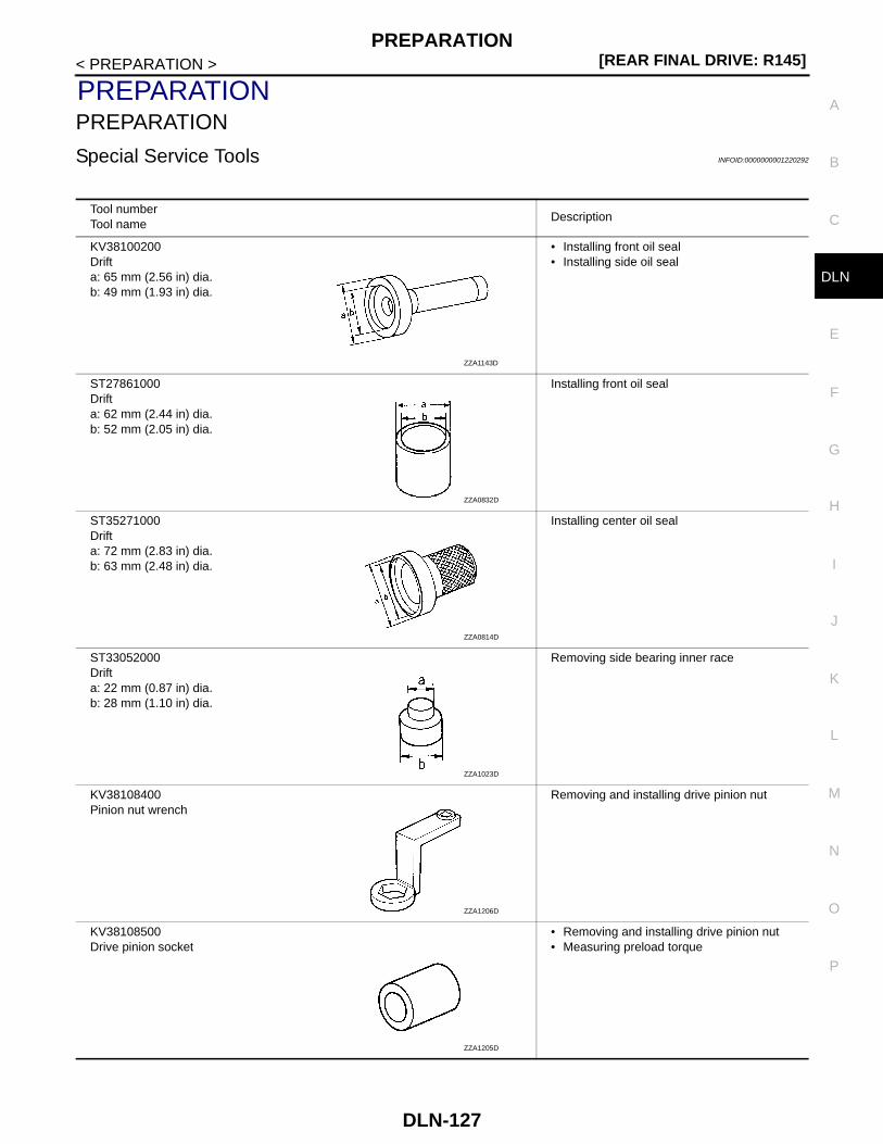
PREPARATION[REAR FINAL DRIVE: R145]
C
E
F
G
H
I
J
K
L
M
A
B
LN
N
O
P
< PREPARATION >
D
PREPARATIONPREPARATION
Special Service Tools INFOID:0000000001220292
Tool numberTool name
Description
KV38100200Drifta: 65 mm (2.56 in) dia.b: 49 mm (1.93 in) dia.
• Installing front oil seal• Installing side oil seal
ST27861000Drifta: 62 mm (2.44 in) dia.b: 52 mm (2.05 in) dia.
Installing front oil seal
ST35271000Drifta: 72 mm (2.83 in) dia.b: 63 mm (2.48 in) dia.
Installing center oil seal
ST33052000Drifta: 22 mm (0.87 in) dia.b: 28 mm (1.10 in) dia.
Removing side bearing inner race
KV38108400Pinion nut wrench
Removing and installing drive pinion nut
KV38108500Drive pinion socket
• Removing and installing drive pinion nut• Measuring preload torque
ZZA1143D
ZZA0832D
ZZA0814D
ZZA1023D
ZZA1206D
ZZA1205D
DLN-127

[REAR FINAL DRIVE: R145]PREPARATION
< PREPARATION >
Commercial Service Tools INFOID:0000000001220293
ST33230000Drifta: 51 mm (2.01 in) dia.b: 41 mm (1.61 in) dia.c: 28.5 mm (1.122 in) dia.
Installing pinion front bearing outer race
ST23860000Drifta: 38 mm (1.50 in) dia.b: 33 mm (1.30 in) dia.
• Installing pinion rear bearing inner race• Installing pinion front bearing inner race
ST3127S000Preload gauge
Measuring preload torque
KV389L0010Dummy cover set
• Checking backlash• Checking drive gear runout• Checking tooth contact
Tool numberTool name
Description
ZZA1046D
ZZA0534D
ZZA0503D
PDIA0894E
Tool name Description
Flange wrench Removing and installing companion flange lock nut
Drifta: 54.5 mm (2.146 in) dia.
Removing and installing gear carrier and rear cover (2 pieces are used)
NT771
PDIA0893E
DLN-128

PREPARATION[REAR FINAL DRIVE: R145]
C
E
F
G
H
I
J
K
L
M
A
B
LN
N
O
P
< PREPARATION >
D
Pin puncha: 4.5 mm (0.177 in) dia.
Removing and installing lock pin
Drifta: 39.7 mm (1.563 in) dia.b: 35 mm (1.38 in) dia.
Installing side bearing inner race
Standa: Approx. 60 mm (2.36 in)b: Approx. 90 mm (3.54 in) dia
Installing pinion front bearing inner race
NT410
ZZA0936D
JPDID0011ZZ
DLN-129
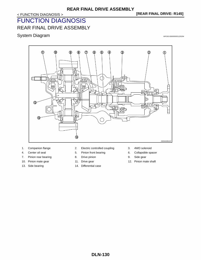
[REAR FINAL DRIVE: R145]REAR FINAL DRIVE ASSEMBLY
< FUNCTION DIAGNOSIS >
FUNCTION DIAGNOSISREAR FINAL DRIVE ASSEMBLY
System Diagram INFOID:0000000001220294
1. Companion flange 2. Electric controlled coupling 3. 4WD solenoid
4. Center oil seal 5. Pinion front bearing 6. Collapsible spacer
7. Pinion rear bearing 8. Drive pinion 9. Side gear
10. Pinion mate gear 11. Drive gear 12. Pinion mate shaft
13. Side bearing 14. Differential case
JSDIA0281ZZ
DLN-130

REAR DIFFERENTIAL GEAR OIL[REAR FINAL DRIVE: R145]
C
E
F
G
H
I
J
K
L
M
A
B
LN
N
O
P
< ON-VEHICLE MAINTENANCE >
D
ON-VEHICLE MAINTENANCEREAR DIFFERENTIAL GEAR OIL
Inspection INFOID:0000000001220295
OIL LEAKEGEMake sure that oil is not leaking from final drive assembly or around it.
OIL LEVEL• Remove filler plug (1) and check oil level from filler plug mounting
hole as shown in the figure.CAUTION:Never start engine while checking oil level.
• Set a new gasket on filler plug and install it on final drive assembly.Refer to DLN-142, "Exploded View".CAUTION:Never reuse gasket.
Draining INFOID:0000000001220296
1. Stop engine.2. Remove drain plug (1) and drain gear oil.3. Set a new gasket on drain plug and install it to final drive assem-
bly and tighten to the specified torque. Refer to DLN-142,"Exploded View".CAUTION:Never reuse gasket.
Refilling INFOID:0000000001220297
1. Remove filler plug (1). Fill with new gear oil until oil level reachesthe specified level near filler plug mounting hole.
2. After refilling oil, check oil level. Set a new gasket to filler plug,then install it to final drive assembly. Refer to DLN-142,"Exploded View".CAUTION:Never reuse gasket.
JSDIA0198ZZ
JSDIA0197ZZ
Oil grade and viscosity : Refer to MA-22, "Fluids and Lubricants".
Oil capacity : Refer to DLN-165, "Gen-eral Specification".
JSDIA0198ZZ
DLN-131

[REAR FINAL DRIVE: R145]FRONT OIL SEAL
< ON-VEHICLE REPAIR >
ON-VEHICLE REPAIRFRONT OIL SEAL
Exploded View INFOID:0000000001220298
MR20DE (M/T, CVT) AND QR25DE (M/T)
M9R (M/T, A/T) AND QR25DE (CVT)
1. Final drive assembly 2. Front oil seal 3. Companion flange
4. Companion flange lock nut
A: Oil seal lip
: Vehicle front
: Apply gear oil.
Refer to GI-4, "Components" for symbols not described on the above.
JSDIA0231GB
1. Final drive assembly 2. Front oil seal 3. Companion flange
4. Companion flange lock nut
A: Oil seal lip
: Vehicle front
JPDID0004GB
DLN-132

FRONT OIL SEAL[REAR FINAL DRIVE: R145]
C
E
F
G
H
I
J
K
L
M
A
B
LN
N
O
P
< ON-VEHICLE REPAIR >
D
Removal and Installation INFOID:0000000001220299
REMOVAL1. Remove rear propeller shaft. Refer to DLN-121, "Exploded View".2. Put matching mark on the thread edge of electric controlled cou-
pling. The matching mark should be in line with the matchingmark on companion flange.CAUTION:For matching mark, use paint. Never damage electric con-trolled coupling.
3. Remove companion flange lock nut, using a flange wrench(commercial service tool). Then remove companion flange.
4. Remove front oil seal from coupling cover, using a flat-bladedscrewdriver.CAUTION:Be careful not to damage coupling cover.
INSTALLATION1. Install front oil seal until it becomes flush with the coupling cover
end, using the drifts.
CAUTION:• Never reuse oil seal.• When installing, never incline oil seal.• Apply multi-purpose grease onto oil seal lips, and gear oil
onto the circumference of oil seal.
: Apply gear oil.
Refer to GI-4, "Components" for symbols not described on the above.
PDIA0455E
JSDIA0199ZZ
JSDIA0200ZZ
A : Drift (SST: KV38100200)
B : Drift (SST: ST27861000)
PDIA0038E
DLN-133

[REAR FINAL DRIVE: R145]FRONT OIL SEAL
< ON-VEHICLE REPAIR >2. Align the matching mark of electric controlled coupling with the
matching mark of companion flange, then install the companionflange.
3. Install companion flange lock nut with a flange wrench (commer-cial service tool), tighten to the specified torque.CAUTION:Never reuse companion flange lock nut.
4. Install rear propeller shaft. Refer to DLN-121, "Exploded View".5. When oil leaks while removing, check oil level after the installa-
tion. Refer to DLN-131, "Inspection".PDIA0455E
DLN-134

SIDE OIL SEAL[REAR FINAL DRIVE: R145]
C
E
F
G
H
I
J
K
L
M
A
B
LN
N
O
P
< ON-VEHICLE REPAIR >
D
SIDE OIL SEAL
Exploded View INFOID:0000000001220300
Removal and Installation INFOID:0000000001220301
REMOVAL1. Remove rear drive shafts. Refer to RAX-13, "Exploded View".2. Remove side oil seals, using a flat-bladed screwdriver.
CAUTION:Be careful not to damage gear carrier and rear cover.
INSTALLATION1. Install side oil seals until it becomes flush with the carrier end,
using the drift (A) (SST: KV38100200).CAUTION:• Never reuse oil seals.• When installing, never incline oil seals.• Apply multi-purpose grease onto oil seal lips, and gear oil
onto the circumference of oil seal.2. Install rear drive shafts. Refer to RAX-13, "Exploded View".3. When oil leaks while removing, check oil level after the installa-
tion. Refer to DLN-131, "Inspection".
1. Final drive assembly 2. Side oil seal
A: Oil seal lip
: Vehicle front
: Apply gear oil.
Refer to GI-4, "Components" for symbols not described on the above.
JSDIA0232ZZ
PDIA0431E
JSDIA0201ZZ
DLN-135

[REAR FINAL DRIVE: R145]ELECTRIC CONTROLLED COUPLING
< ON-VEHICLE REPAIR >
ELECTRIC CONTROLLED COUPLING
Exploded View INFOID:0000000001220302
MR20DE(M/T, CVT) AND QR25DE (M/T)
M9R (M/T, A/T) AND QR25DE (CVT)
1. Final drive assembly 2. Center oil seal 3. 4WD solenoid harness
4. Electric controlled coupling 5. Coupling cover 6. Reamer bolt
7. Connector bracket 8. Front oil seal 9. Companion flange
10. Companion flange lock nut
A: Oil seal lip
: Vehicle front
: Apply gear oil.
: Apply Genuine Liquid Gasket, Three Bond 1217 or equivalent.
Refer to GI-4, "Components" for symbols not described on the above.
JPDID0002GB
1. Final drive assembly 2. Center oil seal 3. 4WD solenoid harness
4. Electric controlled coupling 5. Coupling cover 6. Reamer bolt
7. Connector bracket 8. Front oil seal 9. Companion flange
10. Companion flange lock nut
A: Oil seal lip
JPDID0005GB
DLN-136

ELECTRIC CONTROLLED COUPLING[REAR FINAL DRIVE: R145]
C
E
F
G
H
I
J
K
L
M
A
B
LN
N
O
P
< ON-VEHICLE REPAIR >
D
Removal and Installation INFOID:0000000001220303
REMOVAL1. Remove rear propeller shaft. Refer to DLN-121, "Exploded View".2. Disconnect 4WD solenoid harness connector.3. Remove connector bracket.4. Put matching mark on the thread edge of electric controlled cou-
pling. The matching mark should be in line with the matchingmark on the companion flange.CAUTION:For matching mark, use paint. Never damage electric con-trolled coupling.NOTE:When replacing electric controlled coupling, matching mark isnot necessary.
5. Remove companion flange lock nut, using a flange wrench(commercial service tool).
6. Remove companion flange.7. Remove electric controlled coupling breather hose from cou-
pling cover.
8. Remove coupling cover with electric controlled coupling fromfinal drive assembly.
9. Remove electric controlled coupling from coupling cover.10. Remove 4WD solenoid harness.
: Vehicle front
: Apply gear oil.
: Apply Genuine Liquid Gasket, Three Bond 1217 or equivalent.
Refer to GI-4, "Components" for symbols not described on the above.
PDIA0455E
JSDIA0199ZZ
PDIA0458E
DLN-137

[REAR FINAL DRIVE: R145]ELECTRIC CONTROLLED COUPLING
< ON-VEHICLE REPAIR >11. Remove front oil seal from coupling cover, using a flat-bladed
screwdriver.CAUTION:Be careful not to damage coupling cover.
12. Remove center oil seal from final drive assembly.
INSTALLATION1. Using the drift (A) (SST: ST35271000), install center oil seal (1)
as shown in the figure.
CAUTION:• Never reuse oil seal.• When installing, never incline oil seal.• Apply multi-purpose grease onto oil seal lips, and gear oil
onto the circumference of oil seal.
2. Connect 4WD solenoid harness to electric controlled coupling.
3. Install electric controlled coupling to spline of drive pinion insidegear carrier.CAUTION:• Align the pin on electric controlled coupling with the
groove of gear carrier.• Be careful not to damage center oil seal.
4. Set 4WD solenoid harness guide to gear carrier.
5. Using the drifts, drive front oil seal until it becomes flush with thecoupling cover end.
CAUTION:• Never reuse oil seal.• When installing, never incline oil seal.• Apply multi-purpose grease onto oil seal lips, and gear oil
onto the circumference of oil seal.
PDG0213D
Dimension “D” : 0.8 – 1.2 mm (0.031 – 0.047 in)
JSDIA0260ZZ
PDIA0463E
A : Drift (SST: KV38100200)
B : Drift (SST: ST27861000)
PDIA0449E
DLN-138

ELECTRIC CONTROLLED COUPLING[REAR FINAL DRIVE: R145]
C
E
F
G
H
I
J
K
L
M
A
B
LN
N
O
P
< ON-VEHICLE REPAIR >
D
6. Apply liquid gasket to mating surface of coupling cover. Overlapboth ends of the bead for at least 3 mm (0.12 in).CAUTION:Remove old gasket adhering to the mounting surfaces.Also remove any moisture, oil, or foreign material adheringto the mounting surfaces.
7. Install coupling cover to final drive assembly with arrow facingupward, temporarily tighten reamer bolts to the positions shownin the figure.
8. Tighten reamer bolts and coupling cover mounting bolts to thespecified torque.
9. Install electric controlled coupling breather hose to couplingcover.
10. Install connector bracket, and tighten bolts to the specifiedtorque.
11. Connect 4WD solenoid harness connector.
12. Install companion flange.NOTE:When reusing electric controlled coupling, align the matchingmark of electric controlled coupling with the matching mark ofcompanion flange, then install companion flange.
13. Install companion flange lock nut with flange wrench (commer-cial service tool), tighten to the specified torque.CAUTION:Never reuse companion flange lock nut.
14. Check companion flange runout. Refer to DLN-146, "Adjust-ment".
15. Install rear propeller shaft. Refer to DLN-121, "Exploded View".16. When oil leaks while removing, check oil level after the installation. Refer to DLN-131, "Inspection".
PDIA0613E
SDIA0587E
PDIA0455E
DLN-139

[REAR FINAL DRIVE: R145]REAR FINAL DRIVE ASSEMBLY
< REMOVAL AND INSTALLATION >
REMOVAL AND INSTALLATIONREAR FINAL DRIVE ASSEMBLY
Exploded View INFOID:0000000001220304
Removal and Installation INFOID:0000000001220305
REMOVAL1. Remove rear propeller shaft. Refer to DLN-121, "Exploded View".2. Remove rear drive shafts. Refer to RAX-13, "Exploded View".3. Disconnect 4WD solenoid harness connector.4. Remove rear final drive breather hose and electric controlled coupling breather hose.5. Support final drive assembly with a suitable jack.6. Remove final drive mounting nuts and final drive mounting bolts.
If necessary, remove final drive mounting bracket.CAUTION:Secure final drive assembly to a suitable jack while removing it.
INSTALLATIONNote the following, and install in the reverse order of removal.• When installing each breather hoses, refer to the figure and following.
CAUTION:Make sure there are no pinched or restricted areas on the breather hose caused by bending or wind-ing when installing it.
1. Final drive mounting bracket 2. Washer 3. Final drive assembly
: Vehicle front
Refer to GI-4, "Components" for symbols in the figure.
JPDID0013GB
DLN-140

REAR FINAL DRIVE ASSEMBLY[REAR FINAL DRIVE: R145]
C
E
F
G
H
I
J
K
L
M
A
B
LN
N
O
P
< REMOVAL AND INSTALLATION >
D
- Install rear final drive breather hose (1) to breather connector (2).Install bracket (3) to the breather connector. Check that the paintmark (A) of metal connector (4) faces forward of the vehicle asshown by the arrow.
- Install electric controlled coupling breather hose (1) to metal tubeall way to the point shown by the solid arrow ( ). Check that thecoupling cover (2) of metal tube (3) faces forward of the vehicle asshown by the outline arrow.
• When oil leaks while removing final drive assembly, check oil levelafter the installation. Refer to DLN-131, "Inspection".
: Vehicle front
JSDIA0222ZZ
: Vehicle front
JPDID0014ZZ
DLN-141

[REAR FINAL DRIVE: R145]ELECTRIC CONTROLLED COUPLING
< DISASSEMBLY AND ASSEMBLY >
DISASSEMBLY AND ASSEMBLYELECTRIC CONTROLLED COUPLING
Exploded View INFOID:0000000001220306
MR20DE (M/T, CVT) AND QR25DE (M/T)
1. Filler plug 2. Gasket 3. Drain plug
4. Rear cover 5. Side oil seal 6. Side bearing adjusting shim
7. Side bearing 8. Drive gear 9. Differential case
10. Pinion mate thrust washer 11. Pinion mate gear 12. Pinion mate shaft
13. Lock pin 14. Side gear thrust washer 15. Side gear
16. Drive pinion 17. Pinion rear bearing 18. Drive pinion adjusting shim
19. Collapsible spacer 20. Gear carrier 21. Pinion front bearing
22. Drive pinion nut 23. Center oil seal 24. 4WD solenoid harness
25. Electric controlled coupling 26. Coupling cover 27. Reamer bolt
28. Connector bracket 29. Front oil seal 30. Companion flange
31. Companion flange lock nut
A: Oil seal lip
B: Screw hole
: Apply gear oil.
: Apply anti-corrosive oil.
: Apply Genuine Liquid Gasket, Three Bond 1217 or equivalent.
JPDID0003GB
D L N - 1 4 2

ELECTRIC CONTROLLED COUPLING[REAR FINAL DRIVE: R145]
C
E
F
G
H
I
J
K
L
M
A
B
LN
N
O
P
< DISASSEMBLY AND ASSEMBLY >
D
M9R (M/T, A/T) AND QR25DE (CVT)
: Apply Genuine Medium Strength Thread Locking Sealant, Three Bond 1322B or equivalent.
Refer to GI-4, "Components" for symbols not described on the above.
1. Filler plug 2. Gasket 3. Drain plug
4. Rear cover 5. Side oil seal 6. Side bearing adjusting shim
7. Side bearing 8. Drive gear 9. Differential case
10. Pinion mate thrust washer 11. Pinion mate gear 12. Pinion mate shaft
13. Lock pin 14. Side gear thrust washer 15. Side gear
16. Drive pinion 17. Pinion rear bearing 18. Drive pinion adjusting shim
19. Collapsible spacer 20. Gear carrier 21. Pinion front bearing
22. Drive pinion nut 23. Center oil seal 24. 4WD solenoid harness
25. Electric controlled coupling 26. Coupling cover 27. Reamer bolt
28. Connector bracket 29. Front oil seal 30. Companion flange
31. Companion flange lock nut
A: Oil seal lip
B: Screw hole
: Apply gear oil.
: Apply anti-corrosive oil.
: Apply Genuine Liquid Gasket, Three Bond 1217 or equivalent.
: Apply Genuine Medium Strength Thread Locking Sealant, Three Bond 1322B or equivalent.
Refer to GI-4, "Components" for symbols not described on the above.
JPDID0006GB
DLN-143

[REAR FINAL DRIVE: R145]ELECTRIC CONTROLLED COUPLING
< DISASSEMBLY AND ASSEMBLY >
Disassembly INFOID:0000000001220307
1. Remove connector bracket.2. Put matching mark on the thread edge of electric controlled cou-
pling. The matching mark should be in line with the matchingmark on companion flange.CAUTION:For matching mark, use paint. Never damage electric con-trolled coupling.NOTE:When replacing electric controlled coupling, matching mark isnot necessary.
3. Remove companion flange lock nut, using a flange wrench(commercial service tool).
4. Remove companion flange.5. Remove coupling cover.
6. Remove front oil seal from coupling cover, using flat-bladedscrewdriver.CAUTION:Be careful not to damage coupling cover.
7. Remove electric controlled coupling.8. Remove 4WD solenoid harness.9. Remove center oil seal from gear carrier.
Assembly INFOID:0000000001220308
1. Using the drift (A) (SST: ST35271000), install center oil seal (1)as shown in the figure.
CAUTION:• Never reuse oil seal.• When installing, never incline oil seal.• Apply multi-purpose grease onto oil seal lips, and gear oil
onto the circumference of oil seal.
2. Connect 4WD solenoid harness to electric controlled coupling.
PDIA0455E
PDIA0442E
PDG0213D
Dimension “D” : 0.8 – 1.2 mm (0.031 – 0.047 in)
JSDIA0260ZZ
DLN-144

ELECTRIC CONTROLLED COUPLING[REAR FINAL DRIVE: R145]
C
E
F
G
H
I
J
K
L
M
A
B
LN
N
O
P
< DISASSEMBLY AND ASSEMBLY >
D
3. Install electric controlled coupling to spline of drive pinion insidegear carrier.CAUTION:• Align the pin on electric controlled coupling with the
groove of gear carrier.• Be careful not to damage center oil seal.
4. Set 4WD solenoid harness guide to gear carrier.
5. Using the drifts, drive front oil seal until it becomes flush with thecoupling cover end.
CAUTION:• Never reuse oil seal.• When installing, never incline oil seal.• Apply multi-purpose grease onto oil seal lips, and gear oil
onto the circumference of oil seal.
6. Apply liquid gasket to mating surface of coupling cover. Overlapboth ends of the bead for at least 3 mm (0.12 in).CAUTION:Remove old gasket adhering to the mounting surfaces.Also remove any moisture, oil, or foreign material adheringto the mounting surfaces.
7. Install coupling cover to gear carrier with arrow facing upward,temporarily tighten reamer bolts to the positions shown in thefigure.
8. Tighten reamer bolts and coupling cover mounting bolts to thespecified torque.
9. Install connector bracket, and tighten bolts to the specifiedtorque.
10. Install companion flange.NOTE:When reusing electric controlled coupling, align the matchingmark of electric controlled coupling with the matching mark ofcompanion flange, then install companion flange.
11. Install companion flange lock nut with flange wrench (commer-cial service tool), tighten to the specified torque.CAUTION:Never reuse companion flange lock nut.
12. Check companion flange runout. Refer to DLN-146, "Adjust-ment".
PDIA0463E
A : Drift (SST: KV38100200)
B : Drift (SST: ST27861000)
PDIA0449E
PDIA0613E
SDIA0587E
PDIA0455E
DLN-145

[REAR FINAL DRIVE: R145]ELECTRIC CONTROLLED COUPLING
< DISASSEMBLY AND ASSEMBLY >
Adjustment INFOID:0000000001220309
COMPANION FLANGE RUNOUT1. Fit a dial indicator onto the companion flange face (inner side of
the rear propeller shaft mounting bolt holes).2. Rotate companion flange to check for runout.
3. Fit a test indicator to the inner side of companion flange (socketdiameter).
4. Rotate companion flange to check for runout.
5. If the runout value is outside the runout limit, follow the procedure below to adjust.a. Check for runout while changing the phase between companion flange and drive pinion by 90° step, and
search for the position where the runout is the minimum.b. If the runout value is still outside of the limit after the phase has been changed, replace companion flange.c. If the runout value is still outside of the limit after companion flange has been replaced, possible cause will
be an assembly malfunction of drive pinion and electric controlled coupling, malfunctioning coupling bear-ing, or malfunctioning of electric controlled coupling.
Inspection After Disassembly INFOID:0000000001220310
Clean up the disassembled parts. Then, inspect if the parts are worn or damaged. If so, follow the measuresbelow.
LimitCompanion flange runout : Refer to DLN-165, "Com-
panion Flange Runout".
LimitCompanion flange runout : Refer to DLN-165, "Com-
panion Flange Runout".
PDIA0439E
Content Conditions and Measures
Hypoid gear
• If the gear teeth do not mesh or line-up correctly, determine the cause and adjust or replace as nec-essary.
• If the gears are worn, cracked, damaged, pitted or chipped (by friction) noticeably, replace with new drive gear and drive pinion as a set.
BearingIf any chipped (by friction), pitted, worn, rusted or scratched mark, or unusual noise from the bearing is observed, replace as a bearing assembly (as a new set).
Side gear and Pinion mate gear
• If any cracks or damage on the surface of the tooth is found, replace.• If any worn or chipped mark on the contact sides of the thrust washer is found, replace.
Side gear thrust washer and pinion mate thrust washer
If it is chipped (by friction), damaged, or unusually worn, replace.
Differential case If any wear or crack on the contact sides of the differential case is found, replace.
Companion flangeIf any chipped mark (about 0.1 mm, 0.004 in) or other damage on the contact sides of the lips of the com-panion flange is found, replace.
DLN-146

DIFFERENTIAL ASSEMBLY[REAR FINAL DRIVE: R145]
C
E
F
G
H
I
J
K
L
M
A
B
LN
N
O
P
< DISASSEMBLY AND ASSEMBLY >
D
DIFFERENTIAL ASSEMBLY
Exploded View INFOID:0000000001225969
MR20DE (M/T, CVT) AND QR25DE (M/T)
1. Filler plug 2. Gasket 3. Drain plug
4. Rear cover 5. Side oil seal 6. Side bearing adjusting shim
7. Side bearing 8. Drive gear 9. Differential case
10. Pinion mate thrust washer 11. Pinion mate gear 12. Pinion mate shaft
13. Lock pin 14. Side gear thrust washer 15. Side gear
16. Drive pinion 17. Pinion rear bearing 18. Drive pinion adjusting shim
19. Collapsible spacer 20. Gear carrier 21. Pinion front bearing
22. Drive pinion nut 23. Center oil seal 24. 4WD solenoid harness
25. Electric controlled coupling 26. Coupling cover 27. Reamer bolt
28. Connector bracket 29. Front oil seal 30. Companion flange
31. Companion flange lock nut
A: Oil seal lip
B: Screw hole
: Apply gear oil.
: Apply anti-corrosive oil.
: Apply Genuine Liquid Gasket, Three Bond 1217 or equivalent.
: Apply Genuine Medium Strength Thread Locking Sealant, Three Bond 1322B or equivalent.
Refer to GI-4, "Components" for symbols not described on the above.
JPDID0003GB
DLN-147

[REAR FINAL DRIVE: R145]DIFFERENTIAL ASSEMBLY
< DISASSEMBLY AND ASSEMBLY >
M9R (M/T, A/T) AND QR25DE (CVT)
1. Filler plug 2. Gasket 3. Drain plug
4. Rear cover 5. Side oil seal 6. Side bearing adjusting shim
7. Side bearing 8. Drive gear 9. Differential case
10. Pinion mate thrust washer 11. Pinion mate gear 12. Pinion mate shaft
13. Lock pin 14. Side gear thrust washer 15. Side gear
16. Drive pinion 17. Pinion rear bearing 18. Drive pinion adjusting shim
19. Collapsible spacer 20. Gear carrier 21. Pinion front bearing
22. Drive pinion nut 23. Center oil seal 24. 4WD solenoid harness
25. Electric controlled coupling 26. Coupling cover 27. Reamer bolt
28. Connector bracket 29. Front oil seal 30. Companion flange
31. Companion flange lock nut
A: Oil seal lip
B: Screw hole
: Apply gear oil.
: Apply anti-corrosive oil.
: Apply Genuine Liquid Gasket, Three Bond 1217 or equivalent.
: Apply Genuine Medium Strength Thread Locking Sealant, Three Bond 1322B or equivalent.
Refer to GI-4, "Components" for symbols not described on the above.
JPDID0006GB
DLN-148

DIFFERENTIAL ASSEMBLY[REAR FINAL DRIVE: R145]
C
E
F
G
H
I
J
K
L
M
A
B
LN
N
O
P
< DISASSEMBLY AND ASSEMBLY >
D
Disassembly INFOID:0000000001220312
1. Remove side oil seals, using flat-bladed screwdriver.CAUTION:Be careful not to damage gear carrier and rear cover.
2. Remove rear cover mounting bolts.
3. Set drifts (commercial service tool) to the right and left side bear-ing adjusting shims individually. Press differential case assemblywith side bearing to remove gear carrier assembly and rearcover assembly.CAUTION:The pressure shall be as low as possible to remove gearcarrier assembly and rear cover assembly. The maximumpressure shall be 10 kN (1 ton, 1.0 Imp ton).NOTE:Differential case assembly, side bearings, and adjusting shimsare compressed and integrated in gear carrier and rear cover.
4. Remove drain plug and filler plug.5. Remove side bearing adjusting shims and side bearing outer races.
CAUTION:Mark the side bearing adjusting shims so that the original mounting positions (right/left) can beidentified later.
6. Remove drive gear mounting bolts and then remove drive gearfrom differential case.
7. Remove side bearing inner races, using pullers and the drift(SST: ST33052000).
PDG0216D
PDIA0065E
PDIA0446E
PDIA0459E
DLN-149

[REAR FINAL DRIVE: R145]DIFFERENTIAL ASSEMBLY
< DISASSEMBLY AND ASSEMBLY >8. Pull the lock pin out of pinion mate shaft, using the pin punch
(commercial service tool).
9. Remove pinion mate shaft, pinion mate gears, pinion matethrust washers, side gears, side gear thrust washers from differ-ential case.
Assembly INFOID:0000000001220313
1. Install side gear thrust washers with the same thickness as theones installed prior to disassembly or reinstall the old ones onthe side gears.
2. Install side gears and side gear thrust washers into differentialcase.
3. Align 2 pinion mate gears in diagonally opposite positions, thenrotate and install them into differential case after installing pinionmate thrust washer to pinion mate gear.
PDIA0062E
SDIA0032J
SDIA0193J
SDIA0036J
DLN-150

DIFFERENTIAL ASSEMBLY[REAR FINAL DRIVE: R145]
C
E
F
G
H
I
J
K
L
M
A
B
LN
N
O
P
< DISASSEMBLY AND ASSEMBLY >
D
4. Align the lock pin holes on differential case with shaft, and installpinion mate shaft.
5. Measure side gear end play following the procedure below, and select the appropriate side gear thrustwashers.
a. Place differential case straight up so that side gear to be mea-sured comes upward.
b. Using thickness gauges, measure the clearance between sidegear back and differential case at 3 different positions, whilerotating side gear. Average the 3 readings, and then measurethe clearance. (Measure the clearance of the other side as well.)
CAUTION:To prevent side gear from tilting, insert thickness gaugeswith the same thickness from both sides.
c. If the back clearance is outside the specification, use a thicker/thinner side gear thrust washer to adjust.
CAUTION:Select a side gear thrust washer for right and left individu-ally.
SDIA0037J
PDIA0460E
StandardSide gear back clearance : Refer to DLN-165, "Differ-
ential Side Gear Clear-ance".
When the back clearance is large:Use a thicker thrust washer.
When the back clearance is small:
Use a thinner thrust washer.
SDIA0583E
DLN-151

[REAR FINAL DRIVE: R145]DIFFERENTIAL ASSEMBLY
< DISASSEMBLY AND ASSEMBLY >6. Drive a lock pin into pinion mate shaft, using the pin punch
(commercial service tool).CAUTION:Never reuse lock pin.
7. Press side bearing inner races to differential case, using the drift(commercial service tool).CAUTION:Never reuse side bearing inner races.
8. Apply locking sealant into the thread hole of drive gear.CAUTION:The drive gear back and threaded holes shall be cleanedand decreased sufficiently.
9. Install drive gear to the differential case, and then tighten to thespecified torque.
10. Apply gear oil to side bearings, and install new side bearingadjusting shims (2 pieces for one side) with the same thicknessas the ones installed prior to disassembly or re-install the oldones, with side bearing outer race to differential case.If side bearing adjusting shims have been already selected, usethem.CAUTION:Never reuse side bearing outer race.
11. Set the drifts (commercial service tool) to the right and left sidebearing adjusting shims individually. Compress differential caseassembly and side bearing to install gear carrier assembly to dif-ferential case assembly.CAUTION:• The drift shall be placed on the center of the adjusting
shims.• The pressure shall be as low as possible to install differ-
ential assembly into gear carrier assembly. The maximumpressure shall be 10 kN (1 ton, 1.0 Imp ton).
• If the adjusting shims are installed by tapping, the gearcarrier may be damaged. Avoid tapping.
PDIA0062E
PDIA0052E
SPD554
PDIA0466E
PDIA0064E
DLN-152
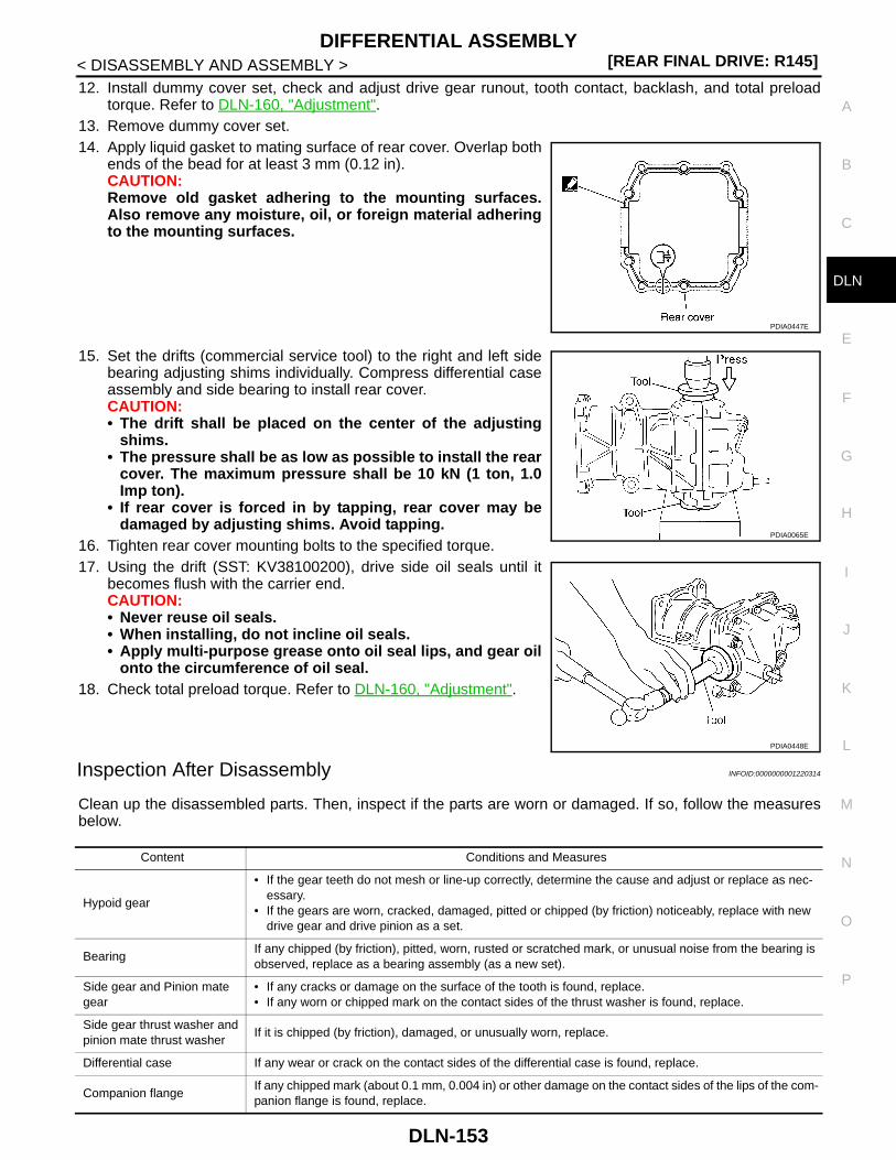
DIFFERENTIAL ASSEMBLY[REAR FINAL DRIVE: R145]
C
E
F
G
H
I
J
K
L
M
A
B
LN
N
O
P
< DISASSEMBLY AND ASSEMBLY >
D
12. Install dummy cover set, check and adjust drive gear runout, tooth contact, backlash, and total preloadtorque. Refer to DLN-160, "Adjustment".
13. Remove dummy cover set.14. Apply liquid gasket to mating surface of rear cover. Overlap both
ends of the bead for at least 3 mm (0.12 in).CAUTION:Remove old gasket adhering to the mounting surfaces.Also remove any moisture, oil, or foreign material adheringto the mounting surfaces.
15. Set the drifts (commercial service tool) to the right and left sidebearing adjusting shims individually. Compress differential caseassembly and side bearing to install rear cover.CAUTION:• The drift shall be placed on the center of the adjusting
shims.• The pressure shall be as low as possible to install the rear
cover. The maximum pressure shall be 10 kN (1 ton, 1.0Imp ton).
• If rear cover is forced in by tapping, rear cover may bedamaged by adjusting shims. Avoid tapping.
16. Tighten rear cover mounting bolts to the specified torque.17. Using the drift (SST: KV38100200), drive side oil seals until it
becomes flush with the carrier end.CAUTION:• Never reuse oil seals.• When installing, do not incline oil seals.• Apply multi-purpose grease onto oil seal lips, and gear oil
onto the circumference of oil seal.18. Check total preload torque. Refer to DLN-160, "Adjustment".
Inspection After Disassembly INFOID:0000000001220314
Clean up the disassembled parts. Then, inspect if the parts are worn or damaged. If so, follow the measuresbelow.
PDIA0447E
PDIA0065E
PDIA0448E
Content Conditions and Measures
Hypoid gear
• If the gear teeth do not mesh or line-up correctly, determine the cause and adjust or replace as nec-essary.
• If the gears are worn, cracked, damaged, pitted or chipped (by friction) noticeably, replace with new drive gear and drive pinion as a set.
BearingIf any chipped (by friction), pitted, worn, rusted or scratched mark, or unusual noise from the bearing is observed, replace as a bearing assembly (as a new set).
Side gear and Pinion mate gear
• If any cracks or damage on the surface of the tooth is found, replace.• If any worn or chipped mark on the contact sides of the thrust washer is found, replace.
Side gear thrust washer and pinion mate thrust washer
If it is chipped (by friction), damaged, or unusually worn, replace.
Differential case If any wear or crack on the contact sides of the differential case is found, replace.
Companion flangeIf any chipped mark (about 0.1 mm, 0.004 in) or other damage on the contact sides of the lips of the com-panion flange is found, replace.
DLN-153

[REAR FINAL DRIVE: R145]DRIVE PINION
< DISASSEMBLY AND ASSEMBLY >
DRIVE PINION
Exploded View INFOID:0000000001225970
MR20DE (M/T, CVT) AND QR25DE (M/T)
1. Filler plug 2. Gasket 3. Drain plug
4. Rear cover 5. Side oil seal 6. Side bearing adjusting shim
7. Side bearing 8. Drive gear 9. Differential case
10. Pinion mate thrust washer 11. Pinion mate gear 12. Pinion mate shaft
13. Lock pin 14. Side gear thrust washer 15. Side gear
16. Drive pinion 17. Pinion rear bearing 18. Drive pinion adjusting shim
19. Collapsible spacer 20. Gear carrier 21. Pinion front bearing
22. Drive pinion nut 23. Center oil seal 24. 4WD solenoid harness
25. Electric controlled coupling 26. Coupling cover 27. Reamer bolt
28. Connector bracket 29. Front oil seal 30. Companion flange
31. Companion flange lock nut
A: Oil seal lip
B: Screw hole
: Apply gear oil.
: Apply anti-corrosive oil.
: Apply Genuine Liquid Gasket, Three Bond 1217 or equivalent.
: Apply Genuine Medium Strength Thread Locking Sealant, Three Bond 1322B or equivalent.
Refer to GI-4, "Components" for symbols not described on the above.
JPDID0003GB
DLN-154

DRIVE PINION[REAR FINAL DRIVE: R145]
C
E
F
G
H
I
J
K
L
M
A
B
LN
N
O
P
< DISASSEMBLY AND ASSEMBLY >
D
M9R (M/T, A/T) AND QR25DE (CVT)
Disassembly INFOID:0000000001220316
1. Remove electric controlled coupling assembly. Refer to DLN-144, "Disassembly".2. Remove differential case assembly. Refer to DLN-149, "Disassembly".
1. Filler plug 2. Gasket 3. Drain plug
4. Rear cover 5. Side oil seal 6. Side bearing adjusting shim
7. Side bearing 8. Drive gear 9. Differential case
10. Pinion mate thrust washer 11. Pinion mate gear 12. Pinion mate shaft
13. Lock pin 14. Side gear thrust washer 15. Side gear
16. Drive pinion 17. Pinion rear bearing 18. Drive pinion adjusting shim
19. Collapsible spacer 20. Gear carrier 21. Pinion front bearing
22. Drive pinion nut 23. Center oil seal 24. 4WD solenoid harness
25. Electric controlled coupling 26. Coupling cover 27. Reamer bolt
28. Connector bracket 29. Front oil seal 30. Companion flange
31. Companion flange lock nut
A: Oil seal lip
B: Screw hole
: Apply gear oil.
: Apply anti-corrosive oil.
: Apply Genuine Liquid Gasket, Three Bond 1217 or equivalent.
: Apply Genuine Medium Strength Thread Locking Sealant, Three Bond 1322B or equivalent.
Refer to GI-4, "Components" for symbols not described on the above.
JPDID0006GB
DLN-155

[REAR FINAL DRIVE: R145]DRIVE PINION
< DISASSEMBLY AND ASSEMBLY >3. Fit drive pinion socket (A) (SST: KV38108500) onto drive pinion
spline. Remove drive pinion nut, using the pinion nut wrench (B)(SST: KV38108400).
4. Press drive pinion assembly out of gear carrier.CAUTION:Never drop drive pinion assembly.
5. Remove pinion front bearing inner race.6. Remove collapsible spacer.
7. Remove pinion rear bearing inner race from drive pinion, usingpuller and bearing puller.
8. Using a brass rod, tap pinion front bearing outer race evenlyfrom the 2 cutouts on gear carrier and remove pinion front bear-ing outer race.CAUTION:Be careful not to damage gear carrier.
9. Using a brass rod, tap drive pinion adjusting shim evenly fromthe 2 cutouts on gear carrier and remove drive pinion adjustingshim and pinion rear bearing outer race.CAUTION:Be careful not to damage the gear carrier.
JSDIA0265ZZ
PDIA0445E
PDIA0179E
SDIA0564E
DLN-156

DRIVE PINION[REAR FINAL DRIVE: R145]
C
E
F
G
H
I
J
K
L
M
A
B
LN
N
O
P
< DISASSEMBLY AND ASSEMBLY >
D
Assembly INFOID:0000000001220317
1. Install a drive pinion adjusting shim of the same thickness aswas installed prior to disassembly. Press pinion rear bearingouter race into gear carrier, using the suitable drift.CAUTION:• At first, using a hammer, tap bearing outer race until it
becomes flush to gear carrier.• Never reuse pinion rear bearing outer race.
2. Press pinion front bearing outer race into gear carrier, using thedrift (SST: 33230000).CAUTION:• At first, using a hammer, tap bearing outer race until it
becomes flush to gear carrier.• Never reuse pinion front bearing outer race.
3. Press pinion rear bearing inner race to drive pinion, using thedrift (SST: ST23860000).CAUTION:Never reuse pinion rear bearing inner race.
4. After checking and adjusting the tooth contact and backlash of the hypoid gear following the procedurebelow.
a. Apply gear oil to the pinion rear bearing, and assemble the drive pinion to the gear carrier.CAUTION:Never assemble a collapsible spacer.
b. Apply gear oil to pinion front bearing, and assemble pinion frontbearing inner race to drive pinion. Using the drifts and stand,press pinion front bearing inner race to drive pinion as far asdrive pinion nut can be tightened.
CAUTION:Never reuse pinion front bearing inner race.
c. Temporarily tighten removed drive pinion nut to drive pinion.NOTE:Use removed drive pinion nut only for the preload measurement.
PDIA0898E
PDIA0067E
PDIA0068E
A : Drift (SST: ST23860000)
B : Drift (commercial service tool)
JPDID0012ZZ
DLN-157

[REAR FINAL DRIVE: R145]DRIVE PINION
< DISASSEMBLY AND ASSEMBLY >d. Fit the drive pinion socket (A) (SST: KV38108500) onto the drive
pinion spline. Using the pinion nut wrench (B) (SST:KV38108400), tighten drive pinion nut to the specified preloadtorque.
CAUTION:Drive pinion nut is tightened with no collapsible spacer. Becareful not to overtighten it. While measuring the preload,tighten it by 5° to 10°.
e. Apply gear oil to side bearings, and install new side bearingadjusting shims with the same thickness or re-install the oldones to the same mounting position they were in prior to disas-sembly. Set the drifts (commercial service tool) to the right andleft. Install differential case assembly to gear carrier.CAUTION:• The drifts shall be placed on the center of the adjusting
shims.• The pressure shall be as low as possible to install gear
carrier assembly to differential assembly. The maximumpressure shall be 10 kN (1 ton, 1.0 Imp ton).
• If adjusting shims are installed by tapping, gear carriermay be damaged. Avoid tapping.
f. Check and adjust the tooth contact. Refer to DLN-160, "Adjustment".g. Check and adjust the backlash. Refer to DLN-160, "Adjustment".h. Remove dummy cover set, and remove differential case assembly.i. Remove drive pinion nut and press drive pinion assembly out of
gear carrier.CAUTION:Never drop drive pinion assembly.
j. Remove pinion front bearing inner race.
C : Preload gauge (SST: ST3127S000)
StandardPinion bearing preload : Refer to DLN-165, "Pre-
load Torque".
JSDIA0266ZZ
PDIA0064E
PDIA0445E
DLN-158
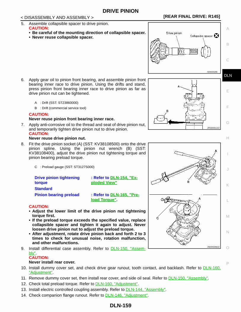
DRIVE PINION[REAR FINAL DRIVE: R145]
C
E
F
G
H
I
J
K
L
M
A
B
LN
N
O
P
< DISASSEMBLY AND ASSEMBLY >
D
5. Assemble collapsible spacer to drive pinion.CAUTION:• Be careful of the mounting direction of collapsible spacer.• Never reuse collapsible spacer.
6. Apply gear oil to pinion front bearing, and assemble pinion frontbearing inner race to drive pinion. Using the drifts and stand,press pinion front bearing inner race to drive pinion as far asdrive pinion nut can be tightened.
CAUTION:Never reuse pinion front bearing inner race.
7. Apply anti-corrosive oil to the thread and seat of drive pinion nut,and temporarily tighten drive pinion nut to drive pinion.CAUTION:Never reuse drive pinion nut.
8. Fit the drive pinion socket (A) (SST: KV38108500) onto the drivepinion spline. Using the pinion nut wrench (B) (SST:KV38108400), adjust the drive pinion nut tightening torque andpinion bearing preload torque.
CAUTION:• Adjust the lower limit of the drive pinion nut tightening
torque first.• If the preload torque exceeds the specified value, replace
collapsible spacer and tighten it again to adjust. Neverloosen drive pinion nut to adjust the preload torque.
• After adjustment, rotate drive pinion back and forth 2 to 3times to check for unusual noise, rotation malfunction,and other malfunctions.
9. Install differential case assembly. Refer to DLN-150, "Assem-bly".CAUTION:Never install rear cover.
10. Install dummy cover set, and check drive gear runout, tooth contact, and backlash. Refer to DLN-160,"Adjustment".
11. Remove dummy cover set, then install rear cover, and side oil seal. Refer to DLN-150, "Assembly".12. Check total preload torque. Refer to DLN-160, "Adjustment".13. Install electric controlled coupling assembly. Refer to DLN-144, "Assembly".14. Check companion flange runout. Refer to DLN-146, "Adjustment".
SDIA2525E
A : Drift (SST: ST23860000)
B : Drift (commercial service tool)
C : Preload gauge (SST: ST3127S000)
Drive pinion tightening torque
: Refer to DLN-154, "Ex-ploded View"
StandardPinion bearing preload : Refer to DLN-165, "Pre-
load Torque".
JPDID0012ZZ
JSDIA0266ZZ
DLN-159

[REAR FINAL DRIVE: R145]DRIVE PINION
< DISASSEMBLY AND ASSEMBLY >
Adjustment INFOID:0000000001220318
TOTAL PRELOAD TORQUE1. Remove electric controlled coupling assembly. Refer to DLN-144, "Disassembly".2. Rotate drive pinion back and forth 2 to 3 times to check for unusual noise and rotation malfunction.3. Rotate drive pinion at least 20 times to check for smooth opera-
tion of the bearing.4. Fit drive pinion socket onto drive pinion spline. Measure the total
preload, using the preload gauge (A) (SST: 3127S000) and drivepinion socket (B) (SST: KV38108500).
NOTE:Total preload torque = Pinion bearing torque + Side bearingtorque
• If measured value is out of the specification, disassemble it to check and adjust each part. Adjust the pinionbearing preload and side bearing preload.Adjust the pinion bearing preload first, then adjust the side bearing preload.
DRIVE GEAR RUNOUT1. Remove rear cover. Refer to DLN-149, "Disassembly".2. Following the procedure below, install a dummy cover set (SST: KV389L0010) to gear carrier.a. Set dummy cover shims to the right and left side bearing adjusting shims.b. Temporarily tighten dummy cover to gear carrier.c. Position dummy cover spacers to dummy cover.d. Tighten rear cover mounting bolts to the specified torque. Refer to DLN-154, "Exploded View".e. Tighten dummy cover spacer mounting bolts evenly to the specified torque.
3. Fit a dial indicator to the drive gear back face.4. Rotate the drive gear to measure runout.
• If the runout is outside of the repair limit, check drive gearassembly condition; foreign material may be caught betweendrive gear and differential case, or differential case or drivegear may be deformed, etc.CAUTION:Replace drive gear and drive pinion as a set.
StandardTotal preload torque : Refer to DLN-165, "Pre-
load Torque".
When the preload torque is largeOn pinion bearings: Replace the collapsible spacer.On side bearings: Use thinner side bearing adjusting shims.
When the preload is smallOn pinion bearings: Tighten the drive pinion nut.On side bearings: Use thicker side bearing adjusting shims.
PDIA0048E
: 5.9 N·m (0.6 kg-m, 52 in-lb)
LimitDrive gear back face runout
: Refer to DLN-165, "Drive Gear Runout".
PDIA0050E
DLN-160

DRIVE PINION[REAR FINAL DRIVE: R145]
C
E
F
G
H
I
J
K
L
M
A
B
LN
N
O
P
< DISASSEMBLY AND ASSEMBLY >
D
TOOTH CONTACT1. Remove rear cover. Refer to DLN-149, "Disassembly".2. Following the procedure below, install a dummy cover set (SST: KV389L0010) to gear carrier.a. Set dummy cover shims to the right and left side bearing adjusting shims.b. Temporarily tighten dummy cover to gear carrier.c. Position dummy cover spacers to dummy cover.d. Tighten rear cover mounting bolts to the specified torque. Refer to DLN-154, "Exploded View".e. Tighten dummy cover spacer mounting bolts evenly to the specified torque.
3. Apply red lead to drive gear.CAUTION:Apply red lead to both the faces of 3 to 4 gears at 4 loca-tions evenly spaced on drive gear.
4. Rotate drive gear back and forth several times, check drive pin-ion gear to drive gear tooth contact.CAUTION:Check tooth contact on drive side and reverse side.
: 5.9 N·m (0.6 kg-m, 52 in-lb)
PDIA0051E
SDIA0570E
DLN-161

[REAR FINAL DRIVE: R145]DRIVE PINION
< DISASSEMBLY AND ASSEMBLY >Tooth Contact Judgment Guide
5. If tooth contact is improperly adjusted, follow the procedurebelow to adjust the pinion height (dimension X).
• If the tooth contact is near the face (face contact), or near theheel (heel contact), thicken drive pinion gear adjusting shim tomove drive pinion closer to drive gear.
SDIA2549E
SDIA0517E
PDIA0440E
DLN-162

DRIVE PINION[REAR FINAL DRIVE: R145]
C
E
F
G
H
I
J
K
L
M
A
B
LN
N
O
P
< DISASSEMBLY AND ASSEMBLY >
D
• If the tooth contact is near the flank (flank contact), or near thetoe (toe contact), thin drive pinion gear adjusting shim to movedrive pinion farther from drive gear.
BACKLASH1. Remove rear cover. Refer to DLN-149, "Disassembly".2. Following the procedure below, install a dummy cover set (SST: KV389L0010) to gear carrier.a. Set dummy cover shims to the right and left side bearing adjusting shims.b. Temporarily tighten dummy cover to gear carrier.c. Position dummy cover spacers to dummy cover.d. Tighten rear cover mounting bolts to the specified torque. Refer to DLN-154, "Exploded View".e. Tighten dummy cover spacer mounting bolts evenly to the specified torque.
3. Fit a dial indicator to the drive gear face to measure the back-lash.
• If the backlash is outside of the specified value, change thethickness of side bearing adjusting shims.
Inspection After Disassembly INFOID:0000000001220319
Clean up the disassembled parts. Then, inspect if the parts are worn or damaged. If so, follow the measuresbelow.
PDIA0441E
: 5.9 N·m (0.6 kg-m, 52 in-lb)
StandardBacklash : Refer to DLN-165, "Back-
lash".
When the backlash is large:Make drive gear back adjusting shims thicker, and drive gear front adjusting shims thinner.
When the backlash is small:Make drive gear back adjusting shims thinner, and drive gear front adjusting shims thicker.
PDIA0049E
Content Conditions and Measures
Hypoid gear
• If the gear teeth do not mesh or line-up correctly, determine the cause and adjust or replace as nec-essary.
• If the gears are worn, cracked, damaged, pitted or chipped (by friction) noticeably, replace with new drive gear and drive pinion as a set.
BearingIf any chipped (by friction), pitted, worn, rusted or scratched mark, or unusual noise from the bearing is observed, replace as a bearing assembly (as a new set).
Side gear and Pinion mate gear
• If any cracks or damage on the surface of the tooth is found, replace.• If any worn or chipped mark on the contact sides of the thrust washer is found, replace.
Side gear thrust washer and pinion mate thrust washer
If it is chipped (by friction), damaged, or unusually worn, replace.
DLN-163

[REAR FINAL DRIVE: R145]DRIVE PINION
< DISASSEMBLY AND ASSEMBLY >
Differential case If any wear or crack on the contact sides of the differential case is found, replace.
Companion flangeIf any chipped mark (about 0.1 mm, 0.004 in) or other damage on the contact sides of the lips of the com-panion flange is found, replace.
Content Conditions and Measures
DLN-164

SERVICE DATA AND SPECIFICATIONS (SDS)[REAR FINAL DRIVE: R145]
C
E
F
G
H
I
J
K
L
M
A
B
LN
N
O
P
< SERVICE DATA AND SPECIFICATIONS (SDS)
D
SERVICE DATA AND SPECIFICATIONS (SDS)SERVICE DATA AND SPECIFICATIONS (SDS)
General Specification INFOID:0000000001220320
Drive Gear Runout INFOID:0000000001220321
Unit: mm (in)
Differential Side Gear Clearance INFOID:0000000001220322
Unit: mm (in)
Preload Torque INFOID:0000000001220323
Unit: N·m (kg-m, in-lb)
Backlash INFOID:0000000001220324
Unit: mm (in)
Companion Flange Runout INFOID:0000000001220325
Unit: mm (in)
Applied model
4WD
MR20DE QR25DE M9R
M/T CVT M/T CVT M/T A/T
Final drive model R145
Gear ratio 2.466
Number of teeth (Drive gear/Drive pinion) 37/15
Oil capacity (Approx.) (lmp pt) 0.55 (1)
Number of pinion gears 2
Drive pinion adjustment spacer type Collapsible
Item Limit
Drive gear back face runout 0.05 (0.0020)
Item Standard
Side gear backlash (Clearance between side gear and differential case)
0.2 (0.008) or less(Each gear should rotate smoothly without excessive resistance
during differential motion.)
Item Standard
Pinion bearing (P1) 0.69 – 1.18 (0.07 – 0.12, 7 – 10)
Side bearing (P2) 0.64 – 0.98 (0.07 – 0.09, 6 – 8)
Side bearing to pinion bearing (Total preload)(Total preload = P1 + P2)
1.33 – 2.16 (0.14 – 0.22, 12 – 19)
Item Standard
Drive gear to drive pinion gear 0.10 – 0.15 (0.0039 – 0.0059)
Item Limit
Companion flange face 0.13 (0.0051)
Inner side of the companion flange 0.19 (0.0075)
DLN-165