Embed Size (px)
Citation preview
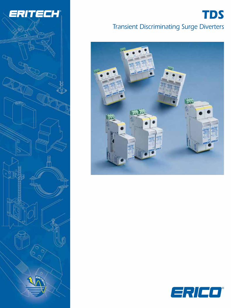
TDSTransient Discriminating Surge Diverters
2
The stress, which an SPD will experience under surge conditions, is a function of many complex and interrelated parameters. These include:
- Location of the SPD(s) within the structure – are they located at the main distribution board or within the facility at secondary board, or even in front of the end-user equipment?
- Method of coupling the lightning strike to the facility – for example, is this via a direct strike to the structure’s LPS, or via induction onto building wiring due to a nearby strike?
- Distribution of lightning currents within the structure – for example, what portion of the lightning current enters the earthing system and what remaining portion seeks a path to remote grounds via the power distribution system and equipotential bonding SPDs?
- Type of power distribution system – the distribution of lightning current on a power distribution system is strongly influenced by the grounding practice for the neutral conductor. For example, in the TN-C system with its multiple earthed neutral, a more direct and lower impedance path to ground is provided for lightning currents than in a TT system.
- Additional conductive services connected to the facility – these will carry a portion of the direct lightning current and therefore reduce the portion which flows through the power distribution system via the lightning equipotential bonding SPD.
- Type of waveshape – it is not possible to simply consider the peak current which the SPD will have to conduct, one also has to consider the waveshape of this surge. It is also not possible to simply equate the areas under the current-time curves (also referred to as the action integral) for SPDs under different waveshapes.
Many attempts have been made to quantify the electrical environment and “threat level” which an SPD will experience at different locations within a facility. The new IECSM standard on lightning protection, IEC 62305-4 “Protection against lightning - Part 4: Electrical and electronic systems within structures” has sought to address this issue by considering the highest surge magnitude which may be presented to an SPD based on the lightning protection level (LPL) being considered. For example, this standard postulates that under a LPL I the magnitude of a direct strike to the structure’s LPS may be as high as 200 kA 10/350. While this level is possible, its statistical probability of occurrence is approximately 1%. In other words, 99% of discharges will be less than this postulated 200 kA peak current level.
An assumption is made that 50% of this current is conducted via the building’s earthing system, and 50% returns via the equipotential bonding SPDs connected to
a three wire plus neutral power distribution system. It is also assumed that no additional conductive service exists. This implies that the portion of the initial 200 kA discharge experienced by each SPD is 25 kA.
Simplified assumptions of current dispersion are useful in considering the possible threat level, which the SPD(s) may experience, but it is important to keep in context the assumptions being made. In the example above, a lightning discharge of 200 kA has been considered. It follows that the threat level to the equipotential bonding SPDs will be less than 25 kA for 99% of the time. In addition, it has been assumed that the waveshape of this current component through the SPD(s) will be of the same waveshape as the initial discharge, namely 10/350, while in reality the waveshape have been altered by the impedance of building wiring, etc.
Many standards have sought to base their considerations on field experience collected overtime. For example, the IEEE® guide to the environment C62.41.1 and the recommended practice C62.41.2 present two scenarios of lightning discharge and different exposure levels under each of these depending on the location where the SPD is installed. In this standard, Scenario II depicts a direct strike to the structure, while Scenario I depicts a nearby strike and the subsequent conducted current into a structure via power and data lines. The highest surge exposure considered feasible to an SPD installed at the service entrance to a facility under Scenario I is 10 kA 8/20, while under Scenario II it is considered to be 10 kA 10/350 (exposure Level 3).
From the above, it is apparent that the selection of the appropriate surge rating for an SPD depends on many complex and interconnected parameters. When addressing such complexities, one needs to keep in mind that one of the more important parameters in selecting an SPD is its limiting voltage performance during the expected surge event, and not the energy withstand which it can handle.
Surge Protection And Surge Ratings
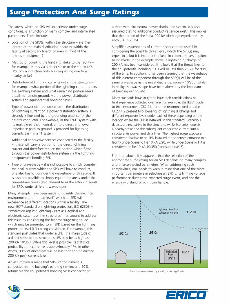
ShieldedRoomLPZ 2
LPZ 0BLPZ 0A
LPZ 1
Lightning terminal collection volume LPZ 0A
Protection zones defined by specific product application.
3
Advanced Technologies – The ERICO® Advantage
Transient Discriminating TechnologyTo meet the fundamental requirements of performance, longer service life and greater safety under real world conditions, ERICO has developed Transient Discriminating (TD) Technology.
This quantum leap in technology adds a level of “intelligence” to the Surge Protection Device enabling it to discriminate between sustained abnormal over-voltage conditions and true transient or surge events. Not only does this help ensure safe operation under practical application, but it also prolongs the life of the protector since permanent disconnects are not required as a means of achieving internal over-voltage protection.
Traditional TechnologiesConventional SPD technologies utilize metal oxide varistors and/or silicon avalanche diodes to clamp or limit transient events. However, these devices are susceptible to sustained 50/60Hz mains over-voltage conditions which often occur during faults to the utility system. Such occurrences present a significant safety hazard when the suppression device attempts to clamp the peak of each half cycle on the mains over-voltage. This condition can cause the device to rapidly accumulate heat and in turn fail with the possibility of inducing a fire hazard.
The Core of TD TechnologyThe secret to ERICO’s Transient Discriminating Technology is its active frequency discrimination circuit. This patented device can discriminate between a temporary over-voltage (TOV) condition
and a very fast transient, which is associated with lightning or switching-induced surges. When the transient frequencies are detected, the patented Quick-Switch within TD activates to allow the robust protection to limit the incoming transient. The frequency discriminating circuit that controls the Quick-Switch helps ensure that the SPD device is immune to the effects of a sustained 50 or 60Hz TOV. This allows the device to keep operating, in order to help provide safe and reliable transient protection, even after an abnormal over-voltage condition has occurred.
Meeting & Exceeding UL® StandardsThe range of surge protection devices from ERICO® employing TD Technology has been specifically designed to meet and exceed the new safety requirements of UL 1449 Edition 3. To meet the abnormal over-voltage testing of UL 1449 Edition 3, many manufacturers of SPD devices have incorporated fuse or thermal disconnect devices which permanently disconnect all protection from the circuit during an over-voltage event. Transient Discriminating Technology on the other hand will allow the SPD device to experience an abnormal over-voltage up to twice its nominal operating voltage and still remain operational even after this event! This allows the device to help provide reliable and continuous protection to your sensitive electronic equipment. TD Technology is especially recommended for any site where sustained over-voltages are known to occur, and where failure of traditional SPD technologies cannot be tolerated.
The UL 1449 testing standard addresses the safety of an SPD device under temporary and abnormal overvoltage conditions, but does not specifically mandate a design that will give a reliable, long length of service in the real world. Specifically, UL 1449 tests that the SPD remains operational at 10% above nominal supply voltage, allowing SPD manufacturers to design products that permanently disconnect just above that. Most reputable manufacturer’s designs allow for up to a 25% overvoltage, while ERICO’s TD Technology gives even greater overhead.
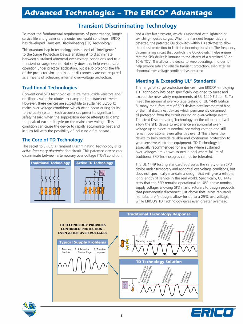
1. Transient Impluse
1. Transient Impluse
2. Substantial Over-voltage
Traditional Technology Active TD Technology
Typical Supply Problems
TD TECHNOLOGY PROVIDES CONTINUED PROTECTION -
EVEN AFTER OVER-VOLTAGES
Traditional Technology Response
TD Technology Solution
Clamping threshold
1. Tr
ansie
nt o
versh
oots
& is
clam
ped
to
appr
ox. 6
00 V
3. P
rote
ctio
n ha
s fai
led.
Equi
pmen
t exp
osed
to
subs
eque
nt tr
ansie
nt
& is
dam
aged
2. Ov
er-vo
ltage
thre
shol
d
exce
eded
, pro
tecti
on
atte
mpt
s to
clam
p,
over
heat
s due
to lo
ng
expo
sure
and
fails
1. Di
scrim
inat
ing
circu
it
dete
cts tr
ansie
nt a
nd
Quick
Switc
h op
erat
ing
clam
ping
tran
sient
2. Pr
otec
tion
does
not
atte
mpt
to cl
amp
supp
ly vo
ltage
3. Pr
otec
tion
still
work
ing
and
cla
mps
tran
sient
4
90 mm(3.54”)
18 mm(0.71”)
68 mm(2.68”)
TDS Surge Diverter - TDS130 Series
TDS130
Model TDS1301TR150 TDS1301TR240Item Number for Europe 702421 702422Nominal Voltage, Un 120-150 VAC 220-240 VACMax Cont. Operating Voltage, Uc 170 VAC 275 VACStand-off Voltage 230 VAC 440 VACFrequency 0-100 HzNominal Discharge Current, In 8 kA 8/20 μs per modeMax Discharge Current, Imax 15 kA 8/20 μs L-N
15 kA 8/20 μs L-PEProtection Modes L-G, L-N, N-GTechnology TD Technology with thermal disconnectShort Circuit Current Rating, Isc 200 kAICBack-up Overcurrent Protection 63 AgL, if supply > 63 AVoltage Protection Level, Up 500 V @ 3 kA (L+N-G)
800 V @ 3 kA (L-N)800 V @ 3 kA (L+N-G)1,500 V @ 3 kA (L-N)
Status N/O, N/C Change-over contact, 250 V~/0.5 A, max 1.5 mm² (#14 AWG) terminalsMechanical fl ag / remote contacts (R model only)
Dimensions H x D x W: mm (in) 90 x 68 x 18 (3.54 x 2.68 x 0.71)Module Width 1 MWeight: kg (lbs) 0.12 (0.26)Enclosure DIN 43 880, UL94V-0 thermoplastic, IP 20 (NEMA-1)Connection 1 mm² to 6 mm² (#18AWG to #10AWG)
Line and Neutral Terminals≤25 mm² (#4AWG) stranded≤35 mm² (#2AWG) solidPE Terminal
Mounting 35 mm top hat DIN railTemperature -40°C to 80°C (-40°F to 176°F)Humidity 0 % to 90 %Approvals CE, IEC® 61643-1, UL® 1449 Ed. 3 Recognized Component Type 2Surge Rated to Meet ANSI®/IEEE® C62.41.2 Cat A, Cat B
IEC 61643-1 Class IIUL® 1449 Ed. 3 In 3 kA mode
Replacement Module TDS130M150 TDS130M240Replacement Module (Europe) 702432 702424
TD
Surges and voltage transients are a major cause of expensive electronic equipment failure and business disruption. Damage may result in the loss of capital outlays, such as computers and communications equipment, as well as consequential loss of revenue and profi ts due to unscheduled system down-time.
The TDS130 series of surge suppressors is designed to provide economical and reliable protection from voltage transients on power distribution systems. The TDS130 is specifi cally designed for the protection of single phase power supplies within instrumentation and control applications. They are conveniently packaged for easy installation on 35 mm DIN rail within control panels.
Transient Discriminating (TD) technology helps ensure reliable and continued operation during sustained and abnormal over-voltage events. Internal thermal disconnect devices help ensure controlled behavior at end-of-life. A visual indicator fl ag provides user-feedback in the event of such operation. The TDS130 provides a set of optional voltage-free contacts for remote signaling that maintenance is required.
The convenient plug-in module and separate base design facilitates replacement of a failed surge module without needing to undo installation wiring.
• TD Technology with thermal disconnect protection
• Compact package, modular DIN rail mounting for limited space requirements
• Three modes of protection: L-N, L-PE & N-PE
• Indication fl ags and voltage-free contacts provide remote status monitoring
• Separate plug and base design facilitates replacement of a failed surge module
• 15kA 8/20μs surge rating per mode
• CE, UL® 1449 Edition 3 Listed
Features
5
18 mm (0.69”)
90 mm(3.54”)
68 mm(2.68”)
Model TDS1501SR150 TDS1501SR240 TDS1501SR277 TDS1501SR560Item Number for Europe 702404 702406 702407 702408Nominal Voltage, Un 120-150 VAC 220-240 VAC 240-277 VAC 480-560 VACMax Cont. Operating Voltage, Uc 170 VAC 275 VAC 320 VAC 610 VACStand-off Voltage 240 VAC 440 VAC 480 VAC 700 VACFrequency 0-100 HzShort Circuit Current Rating, Isc 200 kAICBack-up Overcurrent Protection 125 AgL, if supply > 100 ATechnology TD Technology with thermal disconnectMax Discharge Current, Imax 50 kA 8/20 μsNominal Discharge Current, In 25 kA 8/20 μs 20 kA 8/20Protection Modes Single mode (L-G, L-N or N-G)Voltage Protection Level, Up 400 V @ 3 kA
1.0 kV @ In
700 V @ 3 kA1.2 kV @ In
800 V @ 3 kA1.6 kV @ In
1.8 kV @ 3 kA2.4 kV @ In
Status N/O, N/C Change-over contact, 250 V~/0.5 A, max 1.5 mm² (#14 AWG) terminalsMechanical fl ag / remote contacts (R model only)
Dimensions H x D x W: mm (in) 90 x 68 x 18 (3.54 x 2.68 x 0.69)Module Width 1 MWeight: kg (lbs) 0.12 (0.26)Enclosure DIN 43 880, UL94V-0 thermoplastic, IP 20 (NEMA-1)Connection ≤25 mm² (#4AWG) stranded
≤35 mm² (#2AWG) solidMounting 35 mm top hat DIN railTemperature -40°C to 80°C (-40°F to 176°F)Humidity 0 % to 90 %Approvals CE, IEC® 61643-1, UL® 1449 Ed. 3 Recognized Component Type 2Surge Rated to Meet ANSI®/IEEE® C62.41.2 Cat A, Cat B, Cat C
ANSI®/IEEE® C62.41.2 Scenario II, Exposure 2, 50 kA 8/20 μsIEC 61643-1 Class IIUL® 1449 Ed. 3 In 20 kA mode
Replacement Module TDS150M150 TDS150M240 TDS150M277 TDS150M560
TD
Surges and voltage transients are a major cause of expensive electronic equipment failure and business disruption. Damage may result in the loss of capital outlays, such as computers and communications equipment, as well as consequential loss of revenue and profi ts due to unscheduled system down-time.
The TDS150 series of surge suppressors is designed to provide economical and reliable protection from voltage transients on power distribution systems. They are conveniently packaged for easy installation on 35 mm DIN rail within main distribution panelboards.
Transient Discriminating (TD) technology helps ensure reliable and continued operation during sustained and abnormal over-voltage events. Internal thermal disconnect devices help ensure controlled behavior at end-of-life. A visual indicator fl ag provides user-feedback in the event of such operation. As standard, the TDS150 provides a set of voltage-free contacts for remote signaling that maintenance is required.
The convenient plug-in module and separate base design facilitates replacement of a failed surge module without needing to undo installation wiring.
TDS Surge Diverter - TDS150 Series
TDS150
• TD Technology with thermal disconnect protection
• Compact design fi ts into DIN distribution panel boards and motor control centers
• 35 mm DIN rail mount – DIN 43 880 profi le matches common circuit breakers
• Indication fl ags and voltage-free contacts provide remote status monitoring
• Separate plug and base design facilitates replacement of a failed surge module
• 50kA 8/20μs maximum surge rating provides protection suitable for sub-distribution panels and a long operational life
• Available in various operating voltages to suit most common power distribution systems
• CE, UL® 1449 Edition 3 Listed
Features
6
35 mm(1.38”)
90 mm(3.54”)
68 mm(2.68”)
TDS Surge Diverter - TDS1100 Series
TDS1100
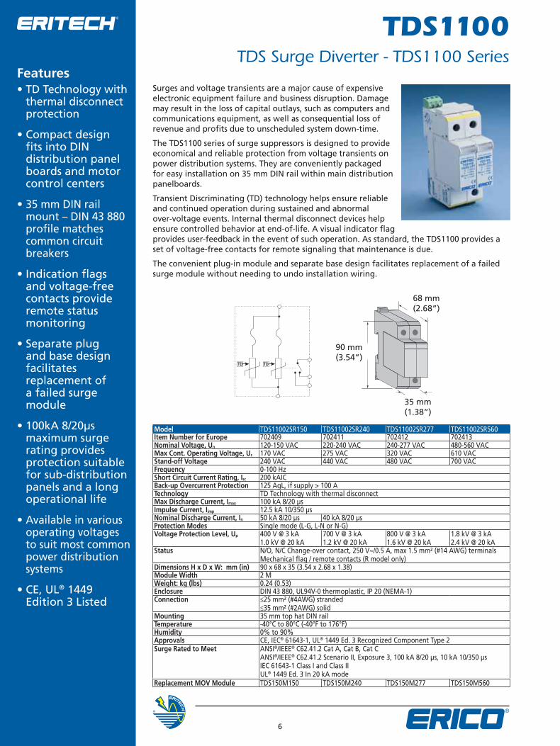
Model TDS11002SR150 TDS11002SR240 TDS11002SR277 TDS11002SR560Item Number for Europe 702409 702411 702412 702413Nominal Voltage, Un 120-150 VAC 220-240 VAC 240-277 VAC 480-560 VACMax Cont. Operating Voltage, Uc 170 VAC 275 VAC 320 VAC 610 VACStand-off Voltage 240 VAC 440 VAC 480 VAC 700 VACFrequency 0-100 HzShort Circuit Current Rating, Isc 200 kAICBack-up Overcurrent Protection 125 AgL, if supply > 100 ATechnology TD Technology with thermal disconnectMax Discharge Current, Imax 100 kA 8/20 μsImpulse Current, Iimp 12.5 kA 10/350 μsNominal Discharge Current, In 50 kA 8/20 μs 40 kA 8/20 μsProtection Modes Single mode (L-G, L-N or N-G)Voltage Protection Level, Up 400 V @ 3 kA
1.0 kV @ 20 kA700 V @ 3 kA1.2 kV @ 20 kA
800 V @ 3 kA1.6 kV @ 20 kA
1.8 kV @ 3 kA2.4 kV @ 20 kA
Status N/O, N/C Change-over contact, 250 V~/0.5 A, max 1.5 mm² (#14 AWG) terminalsMechanical fl ag / remote contacts (R model only)
Dimensions H x D x W: mm (in) 90 x 68 x 35 (3.54 x 2.68 x 1.38)Module Width 2 MWeight: kg (lbs) 0.24 (0.53)Enclosure DIN 43 880, UL94V-0 thermoplastic, IP 20 (NEMA-1)Connection ≤25 mm² (#4AWG) stranded
≤35 mm² (#2AWG) solidMounting 35 mm top hat DIN railTemperature -40°C to 80°C (-40°F to 176°F)Humidity 0% to 90%Approvals CE, IEC® 61643-1, UL® 1449 Ed. 3 Recognized Component Type 2Surge Rated to Meet ANSI®/IEEE® C62.41.2 Cat A, Cat B, Cat C
ANSI®/IEEE® C62.41.2 Scenario II, Exposure 3, 100 kA 8/20 μs, 10 kA 10/350 μsIEC 61643-1 Class I and Class IIUL® 1449 Ed. 3 In 20 kA mode
Replacement MOV Module TDS150M150 TDS150M240 TDS150M277 TDS150M560
TDTD
Surges and voltage transients are a major cause of expensive electronic equipment failure and business disruption. Damage may result in the loss of capital outlays, such as computers and communications equipment, as well as consequential loss of revenue and profi ts due to unscheduled system down-time.
The TDS1100 series of surge suppressors is designed to provide economical and reliable protection from voltage transients on power distribution systems. They are conveniently packaged for easy installation on 35 mm DIN rail within main distribution panelboards.
Transient Discriminating (TD) technology helps ensure reliable and continued operation during sustained and abnormal over-voltage events. Internal thermal disconnect devices help ensure controlled behavior at end-of-life. A visual indicator fl ag provides user-feedback in the event of such operation. As standard, the TDS1100 provides a set of voltage-free contacts for remote signaling that maintenance is due.
The convenient plug-in module and separate base design facilitates replacement of a failed surge module without needing to undo installation wiring.
• TD Technology with thermal disconnect protection
• Compact design fi ts into DIN distribution panel boards and motor control centers
• 35 mm DIN rail mount – DIN 43 880 profi le matches common circuit breakers
• Indication fl ags and voltage-free contacts provide remote status monitoring
• Separate plug and base design facilitates replacement of a failed surge module
• 100kA 8/20μs maximum surge rating provides protection suitable for sub-distribution panels and a long operational life
• Available in various operating voltages to suit most common power distribution systems
• CE, UL® 1449 Edition 3 Listed
Features
7
TDS350TNC TDS50120/240
TDS350TT 70 mm (2.76”)
90 mm(3.54”)
53 mm (2.07”)
68 mm(2.68”)
68 mm(2.68”)
90 mm(3.54”)
TDS Surge Diverter - TDS350 Series
TDS350
TD TD TD
PE
N
TDTD TD
TD TD TD
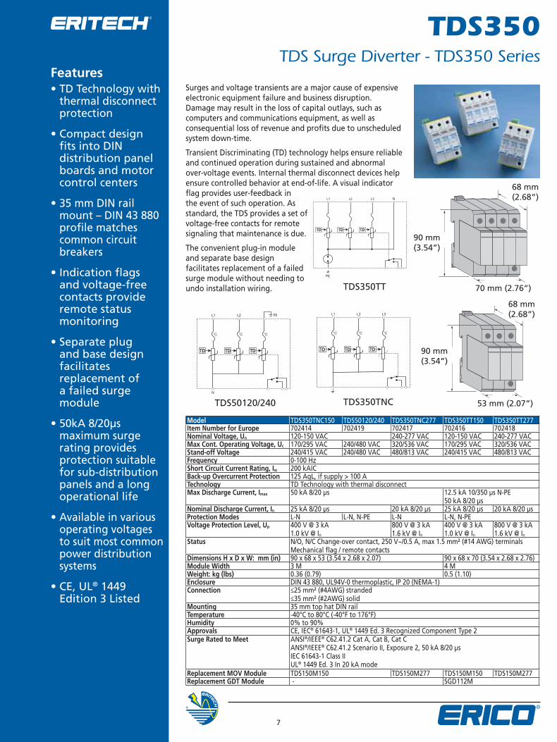
Surges and voltage transients are a major cause of expensive electronic equipment failure and business disruption. Damage may result in the loss of capital outlays, such as computers and communications equipment, as well as consequential loss of revenue and profi ts due to unscheduled system down-time.
Transient Discriminating (TD) technology helps ensure reliable and continued operation during sustained and abnormal over-voltage events. Internal thermal disconnect devices help ensure controlled behavior at end-of-life. A visual indicator fl ag provides user-feedback in the event of such operation. As standard, the TDS provides a set of voltage-free contacts for remote signaling that maintenance is due.
The convenient plug-in module and separate base design facilitates replacement of a failed surge module without needing to undo installation wiring.
• TD Technology with thermal disconnect protection
• Compact design fi ts into DIN distribution panel boards and motor control centers
• 35 mm DIN rail mount – DIN 43 880 profi le matches common circuit breakers
• Indication fl ags and voltage-free contacts provide remote status monitoring
• Separate plug and base design facilitates replacement of a failed surge module
• 50kA 8/20μs maximum surge rating provides protection suitable for sub-distribution panels and a long operational life
• Available in various operating voltages to suit most common power distribution systems
• CE, UL® 1449 Edition 3 Listed
Features
Model TDS350TNC150 TDS50120/240 TDS350TNC277 TDS350TT150 TDS350TT277Item Number for Europe 702414 702419 702417 702416 702418Nominal Voltage, Un 120-150 VAC 240-277 VAC 120-150 VAC 240-277 VACMax Cont. Operating Voltage, Uc 170/295 VAC 240/480 VAC 320/536 VAC 170/295 VAC 320/536 VACStand-off Voltage 240/415 VAC 240/480 VAC 480/813 VAC 240/415 VAC 480/813 VACFrequency 0-100 HzShort Circuit Current Rating, Isc 200 kAICBack-up Overcurrent Protection 125 AgL, if supply > 100 ATechnology TD Technology with thermal disconnectMax Discharge Current, Imax 50 kA 8/20 μs 12.5 kA 10/350 μs N-PE
50 kA 8/20 μsNominal Discharge Current, In 25 kA 8/20 μs 20 kA 8/20 μs 25 kA 8/20 μs 20 kA 8/20 μsProtection Modes L-N L-N, N-PE L-N L-N, N-PEVoltage Protection Level, Up 400 V @ 3 kA
1.0 kV @ In
800 V @ 3 kA1.6 kV @ In
400 V @ 3 kA1.0 kV @ In
800 V @ 3 kA1.6 kV @ In
Status N/O, N/C Change-over contact, 250 V~/0.5 A, max 1.5 mm² (#14 AWG) terminalsMechanical fl ag / remote contacts
Dimensions H x D x W: mm (in) 90 x 68 x 53 (3.54 x 2.68 x 2.07) 90 x 68 x 70 (3.54 x 2.68 x 2.76)Module Width 3 M 4 MWeight: kg (lbs) 0.36 (0.79) 0.5 (1.10)Enclosure DIN 43 880, UL94V-0 thermoplastic, IP 20 (NEMA-1)Connection ≤25 mm² (#4AWG) stranded
≤35 mm² (#2AWG) solidMounting 35 mm top hat DIN railTemperature -40°C to 80°C (-40°F to 176°F)Humidity 0% to 90%Approvals CE, IEC® 61643-1, UL® 1449 Ed. 3 Recognized Component Type 2Surge Rated to Meet ANSI®/IEEE® C62.41.2 Cat A, Cat B, Cat C
ANSI®/IEEE® C62.41.2 Scenario II, Exposure 2, 50 kA 8/20 μsIEC 61643-1 Class IIUL® 1449 Ed. 3 In 20 kA mode
Replacement MOV Module TDS150M150 TDS150M277 TDS150M150 TDS150M277Replacement GDT Module - SGD112M
WARNINGERICO products shall be installed and used only as indicated in ERICO’s product instruction sheets and training materials. Instruction sheets are available at www.erico.com and from your ERICO customer service representative. Improper installation, misuse, misapplication or other failure to completely follow ERICO’s instructions and warnings may cause product malfunction, property damage, serious bodily injury and death.
ANSI is a registered trademark of the American National Standards Institute. IEC is a registered trademark of the International Electrotechnical Commission. IEEE is a registered trademark of the Institute of Electrical and Electronics Engineers, Incorporated. NEMA is a registered trademark of the National Electrical Manufacturers Association. UL is a registered trademark of Underwriters Laboratories, Inc.
www.erico.com
E712B-WWEN E798LT07WWEN 01110.6M8 Copyright ©2009 ERICO International Corporation. All rights reserved.CADDY, CADWELD, CRITEC, ERICO, ERIFLEX, ERITECH, and LENTON are registered trademarks of ERICO International Corporation.
AUSTRALIAPhone 1800-263-508Fax 1800-423-091
NORWAYPhone 800-100-73Fax 800-100-66
HUNGARYPhone 06-800-16538Fax +31-13-583-5406
CHINAPhone +86-21-3430-4878 Fax +86-21-5831-8177
SWITZERLANDPhone 0800-55-86-97Fax 0800-55-96-15
BELGIUMPhone 0800-757-48Fax 0800-757-60
POLANDPhone +48-71-349-04-60Fax +48-71-349-04-61
INDONESIAPhone +62-21-575-0941Fax +62-21-575-0942
DENMARKPhone 808-89-373Fax 808-89-372
THAILANDPhone +66-2-267-5776Fax +66-2-636-6988
BRAZILPhone +55-11-3623-4333Fax +55-11-3621-4066
SINGAPOREPhone +65-6-268-3433Fax +65-6-268-1389
ITALYPhone 800-870-938Fax 800-873-935
FRANCEPhone 0800-901-793Fax 0800-902-024
UNITED ARAB EMIRATESPhone +971-4-881-7250Fax +971-4-881-7270
CANADAPhone +1-800-677-9089Fax +1-800-677-8131
SPAINPhone 900-993-154Fax 900-993-106
MEXICOPhone +52-55-5260-5991Fax +52-55-5260-3310
GERMANYPhone 0-800-189-0272Fax 0-800-189-0274
UNITED KINGDOMPhone +0808-2344-670Fax +0808-2344-676
CHILEPhone +56-2-370-2908Fax +56-2-369-5657
SWEDENPhone 020-790-908Fax 020-798-964
NETHERLANDSPhone +31-13-583-5400Fax +31-13-583-5499
HONG KONGPhone +852-2764-8808Fax +852-2764-4486
UNITED STATESPhone +1-440-248-0100Fax +1-440-248-0723