Embed Size (px)
Citation preview
1Transformer ad hoc IEEE 802.3at Task Force, November 2007, Atlanta v1
Transformer and Channel ad hoc
November 2007
Fred SchindlerCisco Systems
1 ad hoc with an average attendance of 21 people since the last IEEE meeting. People that attended since the last IEEE meeting are shown in bold.
Alan Linda PulseAndrew Smith Power IntegrationAnoop Vetteth Cisco SystemsDan Dove HP Procurve NetworkingDavid Law 3COMFred Schindler Cisco SystemsGeoff Thompson Nortel NetworksHugh Barrass Cisco SystemsJeff H. HaloJoe Berry BelJohnny Chen MolexJoseph Maggiollino BroadcomMark M. PulseMatthew Landry Silicon LabsMohamad PulsePeter LiuRamesh Sastry Cisco SystemsSteve Sedio FoxconnTerry Cobb SystimaxThuyen Dinh PulseVictor Renteria Pulse
2Transformer ad hoc IEEE 802.3at Task Force, November 2007, Atlanta
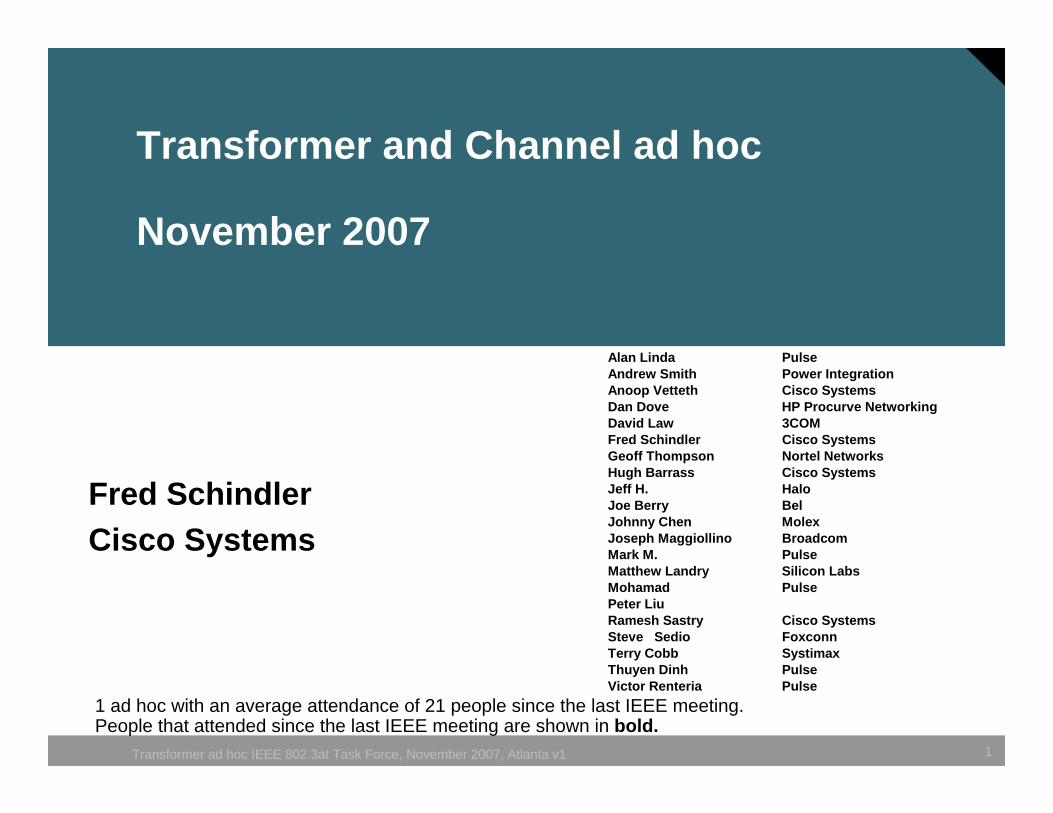
Agenda
• Review the IEEE 802.3 channel model• Ad Hoc recommendations• Current unbalance• Current unbalance affect on the transformer• Next step.
3Transformer ad hoc IEEE 802.3at Task Force, November 2007, Atlanta
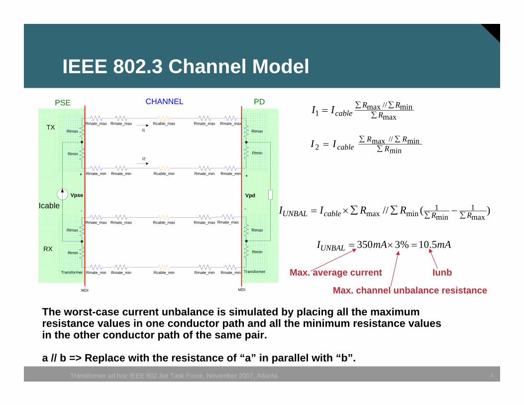
IEEE 802.3 Channel Model
maxmin//max
1 RRR
cableII ∑∑∑=
minmin//max
2 RRR
cableII ∑∑∑=
)(//max1
min1
minmax RRcableUNBAL RRII ∑∑ −∑∑×=
The worst-case current unbalance is simulated by placing all the maximum resistance values in one conductor path and all the minimum resistance values in the other conductor path of the same pair.
a // b => Replace with the resistance of “a” in parallel with “b”.
Rmate_min Rmate_min Rmate_min Rmate_minRcable_min
Rtmax Rtmax
RtminRtmin
Rmate_max Rmate_max Rmate_max Rmate_maxRcable_max
Rmate_min Rmate_min Rmate_min Rmate_minRcable_min
Rtmax Rtmax
RtminRtmin
Rmate_max Rmate_max Rmate_max Rmate_maxRcable_max
TX
RX
PDCHANNELPSE
+
-
I1
I2
Vpd
Icable
+
-
Vpse
TransformerTransformer
MDI MDI
mAmAIUNBAL 5.10%3350 =×=
Max. average current
Max. channel unbalance resistance
Iunb
4Transformer ad hoc IEEE 802.3at Task Force, November 2007, Atlanta
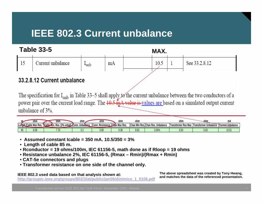
IEEE 802.3 Current unbalance
m ohm ohm ohm ohm ohm ohm ohm ohm mALength Cable Max Res. Cable Min. Res. (2% unbal) Conn. Unbalance Conn. Resistance Chan Max Res. Chan Min Res. Chan Res. Unbalance Transformer Res Max Transformer Unbalance Current Unbalance
85 8.08 7.76 0.2 0.80 9.38 8.83 3.00% 0.50 0.03 10.51
Table 33-5
IEEE 802.3 used data based on that analysis shown at: http://grouper.ieee.org/groups/802/3/at/public/jan06/diminico_1_0106.pdf
MAX.
The above spreadsheet was created by Tony Hwang, and matches the data of the referenced presentation.
• Assumed constant Icable = 350 mA. 10.5/350 = 3%• Length of cable 85 m.• Rconductor = 19 ohms/100m, IEC 61156-5, math done as if Rloop = 19 ohms• Resistance unbalance 2%, IEC 61156-5, (Rmax – Rmin)/(Rmax + Rmin)• CAT-5e connectors and plugs• Transformer resistance on one side of the channel only.
5Transformer ad hoc IEEE 802.3at Task Force, November 2007, Atlanta
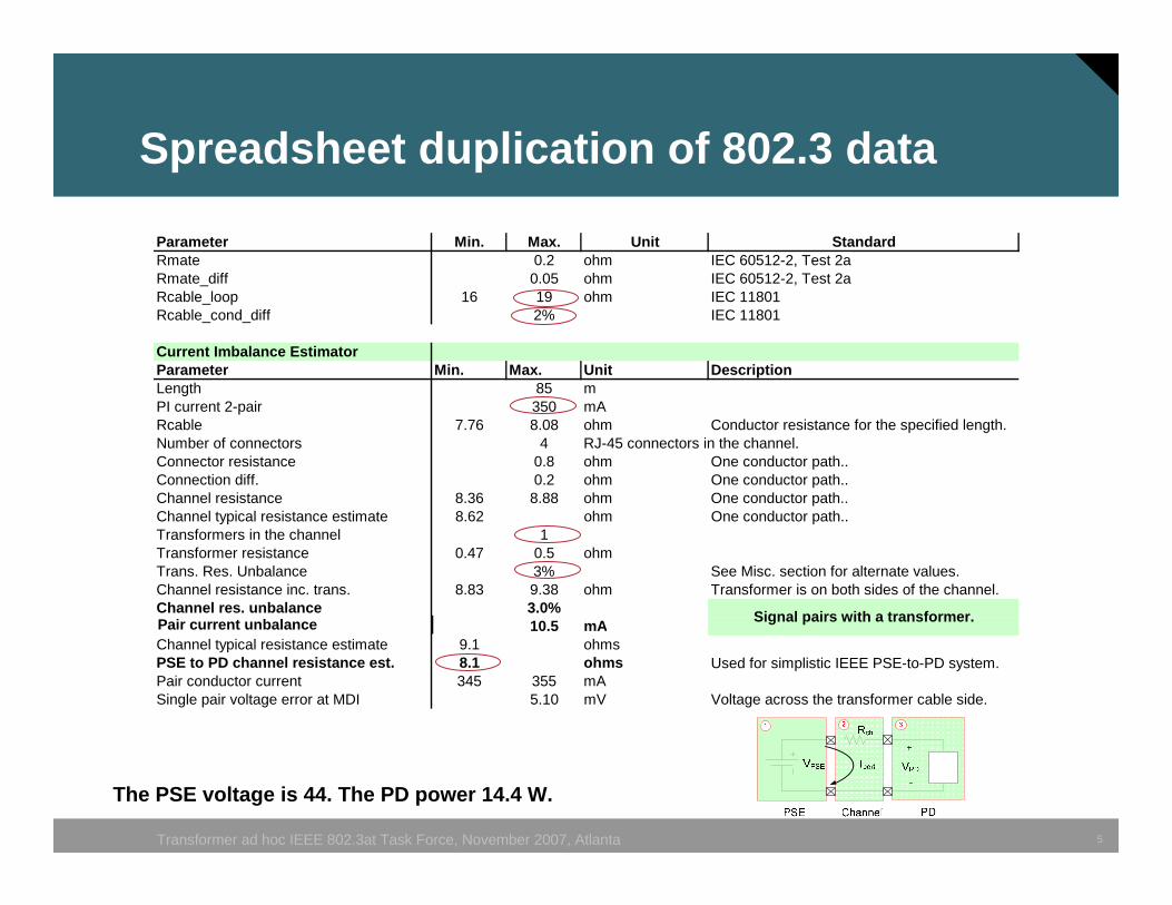
Parameter Min. Max. Unit StandardRmate 0.2 ohm IEC 60512-2, Test 2aRmate_diff 0.05 ohm IEC 60512-2, Test 2aRcable_loop 16 19 ohm IEC 11801Rcable_cond_diff 2% IEC 11801
Current Imbalance EstimatorParameter Min. Max. Unit DescriptionLength 85 mPI current 2-pair 350 mARcable 7.76 8.08 ohm Conductor resistance for the specified length.Number of connectors 4 RJ-45 connectors in the channel.Connector resistance 0.8 ohm One conductor path..Connection diff. 0.2 ohm One conductor path..Channel resistance 8.36 8.88 ohm One conductor path..Channel typical resistance estimate 8.62 ohm One conductor path..Transformers in the channel 1Transformer resistance 0.47 0.5 ohmTrans. Res. Unbalance 3% See Misc. section for alternate values.Channel resistance inc. trans. 8.83 9.38 ohm Transformer is on both sides of the channel.Channel res. unbalance 3.0%Pair current imbalance 10.5 mAChannel typical resistance estimate 9.1 ohmsPSE to PD channel resistance est. 8.1 ohms Used for simplistic IEEE PSE-to-PD system.Pair conductor current 345 355 mASingle pair voltage error at MDI 5.10 mV Voltage across the transformer cable side.
Signal pairs with a transformer.
Spreadsheet duplication of 802.3 data
The PSE voltage is 44. The PD power 14.4 W.
Pair current unbalance
6Transformer ad hoc IEEE 802.3at Task Force, November 2007, Atlanta
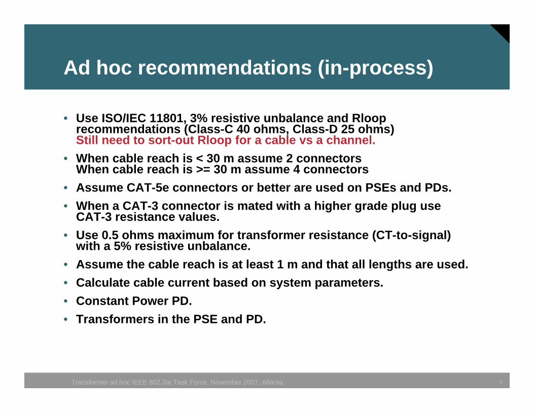
Ad hoc recommendations (in-process)
• Use ISO/IEC 11801, 3% resistive unbalance and Rlooprecommendations (Class-C 40 ohms, Class-D 25 ohms)Still need to sort-out Rloop for a cable vs a channel.
• When cable reach is < 30 m assume 2 connectorsWhen cable reach is >= 30 m assume 4 connectors
• Assume CAT-5e connectors or better are used on PSEs and PDs.• When a CAT-3 connector is mated with a higher grade plug use
CAT-3 resistance values.• Use 0.5 ohms maximum for transformer resistance (CT-to-signal)
with a 5% resistive unbalance.• Assume the cable reach is at least 1 m and that all lengths are used.• Calculate cable current based on system parameters.• Constant Power PD.• Transformers in the PSE and PD.
7Transformer ad hoc IEEE 802.3at Task Force, November 2007, Atlanta
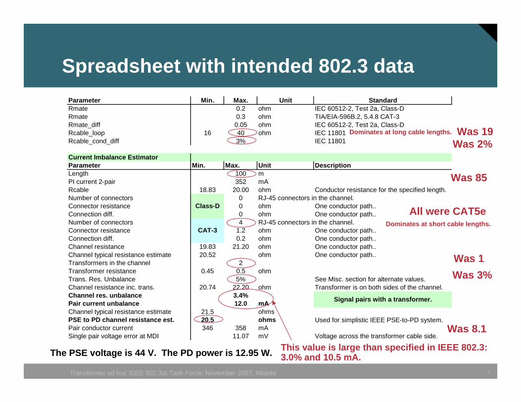
Parameter Min. Max. Unit StandardRmate 0.2 ohm IEC 60512-2, Test 2a, Class-DRmate 0.3 ohm TIA/EIA-596B.2, 5.4.8 CAT-3Rmate_diff 0.05 ohm IEC 60512-2, Test 2a, Class-DRcable_loop 16 40 ohm IEC 11801Rcable_cond_diff 3% IEC 11801
Current Imbalance EstimatorParameter Min. Max. Unit DescriptionLength 100 mPI current 2-pair 352 mARcable 18.83 20.00 ohm Conductor resistance for the specified length.Number of connectors 0 RJ-45 connectors in the channel.Connector resistance 0 ohm One conductor path..Connection diff. 0 ohm One conductor path..Number of connectors 4 RJ-45 connectors in the channel.Connector resistance 1.2 ohm One conductor path..Connection diff. 0.2 ohm One conductor path..Channel resistance 19.83 21.20 ohm One conductor path..Channel typical resistance estimate 20.52 ohm One conductor path..Transformers in the channel 2Transformer resistance 0.45 0.5 ohmTrans. Res. Unbalance 5% See Misc. section for alternate values.Channel resistance inc. trans. 20.74 22.20 ohm Transformer is on both sides of the channel.Channel res. unbalance 3.4%Pair current unbalance 12.0 mAChannel typical resistance estimate 21.5 ohmsPSE to PD channel resistance est. 20.5 ohms Used for simplistic IEEE PSE-to-PD system.Pair conductor current 346 358 mASingle pair voltage error at MDI 11.07 mV Voltage across the transformer cable side.
Signal pairs with a transformer.
CAT-3
Class-D
Spreadsheet with intended 802.3 data
Was 19Was 2%
Was 85
Was 1
Was 8.1
The PSE voltage is 44 V. The PD power is 12.95 W. This value is large than specified in IEEE 802.3:3.0% and 10.5 mA.
All were CAT5e
Dominates at long cable lengths.
Dominates at short cable lengths.
Was 3%
8Transformer ad hoc IEEE 802.3at Task Force, November 2007, Atlanta
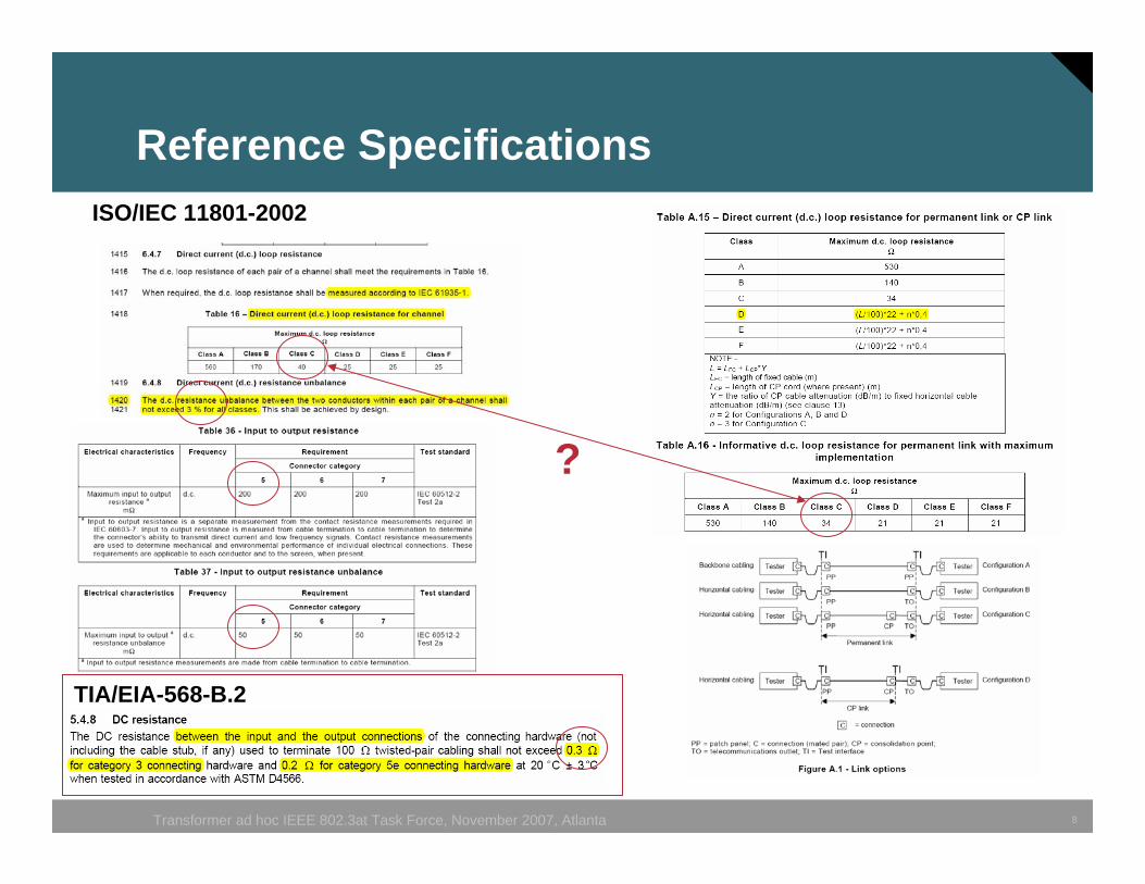
Reference Specifications
TIA/EIA-568-B.2
ISO/IEC 11801-2002
?
9Transformer ad hoc IEEE 802.3at Task Force, November 2007, Atlanta
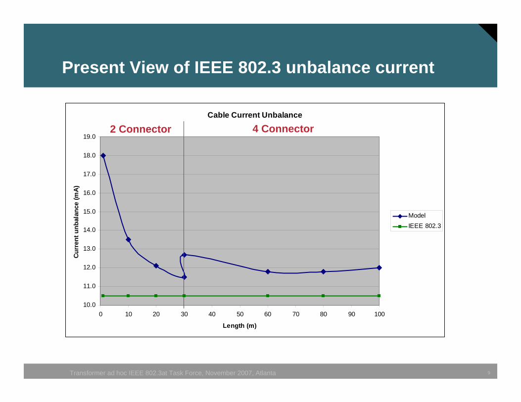
Cable Current Unbalance
10.0
11.0
12.0
13.0
14.0
15.0
16.0
17.0
18.0
19.0
0 10 20 30 40 50 60 70 80 90 100
Length (m)
Curr
ent u
nbal
ance
(mA)
ModelIEEE 802.3
Present View of IEEE 802.3 unbalance current
2 Connector 4 Connector
10Transformer ad hoc IEEE 802.3at Task Force, November 2007, Atlanta
Cable Current Unbalance
10.0
11.0
12.0
13.0
14.0
15.0
16.0
17.0
18.0
19.0
0 10 20 30 40 50 60 70 80 90 100
Length (m)
Curr
ent u
nbal
ance
(mA
)
ModelIEEE 802.3
2 Connector 4 Connector
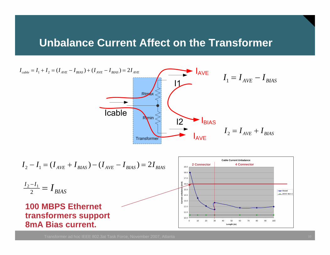
Unbalance Current Affect on the Transformer
Rtmax
Rtmin
Transformer
AVE
AVE
BIAS
BIASAVE III −=1
BIASAVE III +=2
BIASBIASAVEBIASAVE IIIIIII 2)()(12 =−−+=−
BIASII I=−
212
AVEBIASAVEBIASAVEcable IIIIIIII 2)()(21 =−+−=+=
100 MBPS Ethernet transformers support 8mA Bias current.
11Transformer ad hoc IEEE 802.3at Task Force, November 2007, Atlanta
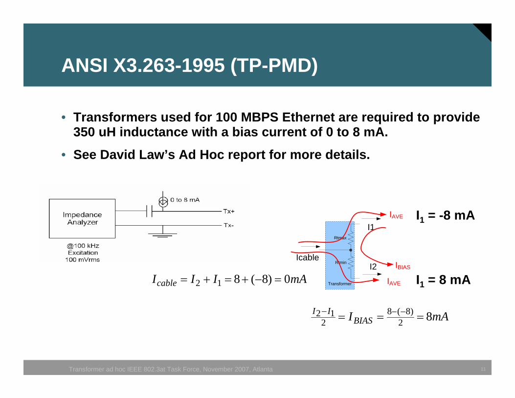
ANSI X3.263-1995 (TP-PMD)
• Transformers used for 100 MBPS Ethernet are required to provide 350 uH inductance with a bias current of 0 to 8 mA.
• See David Law’s Ad Hoc report for more details.
Rtmax
Rtmin
Transformer
Icable
I1
I2
IAVE
IAVE
IBIAS
I1 = -8 mA
I1 = 8 mA
mAIBIASII 82
)8(82
12 === −−−
mAIIIcable 0)8(812 =−+=+=
12Transformer ad hoc IEEE 802.3at Task Force, November 2007, Atlanta
Next Step
• Review parameters selected for legacy PoE.
• Is worst-case probable?
• Select parameters for PoE plus.


![[ AD Hoc Networks ] by: Farhad Rad 1. Agenda : Definition of an Ad Hoc Networks routing in Ad Hoc Networks IEEE 802.11 security in Ad Hoc Networks Multicasting](https://img.dokumen.tips/doc/110x75/56649d305503460f94a0832b/-ad-hoc-networks-by-farhad-rad-1-agenda-definition-of-an-ad-hoc-networks.jpg)