Embed Size (px)
Citation preview
Tranquility® Modular
(TSM) Vertical Stack Series
Commercial
Vertical Stack
Water-Source Heat Pumps
Installation, Operation
& Maintenance
97B0111N01Rev.: 26 August, 2015
Table of Contents
General Information 3TSM Model Nomenclature - Cabinet 4Cabinet Slot Dimensions and Riser Arrangements 5TSM Cabinet Confi gurations 6TSM Model Nomenclature - Chassis 7Accessory Nomenclature 8Pre-Installation Information 9Riser & Cabinet Installation 10Cabinet Installation 13Water-Loop Heat Pump Applications 20Ground-Loop Heat Pump Applications 21Ground-Water Heat Pump Applications 22Water Quality Standards 23Electrical Wiring - Line Voltage 24Blower Performance Data 25Electrical Wiring - Low Voltage 27Thermostat Installation 28Chassis Pre-Installation 29Hose Kit & Chassis Installation 30Start-Up Preparation 33TSM Series Wiring Diagram Matrix 34Connections to DDC Options 35Typical Wiring Diagrams 36-39CXM Control 40DXM2 Control 41Safety Features - CXM/DXM2 Controls 43Unit Commissioning and Operating Conditions 45Unit and System Checkout 46Unit Start-Up Procedures 47Unit Operating Pressures and Temperatures 48Coax Water Pressure Drop 51Start-Up Log Sheet 52Preventive Maintenance 53Functional Troubleshooting 54Performance Troubleshooting 55Harness Part Numbers 56-58Troubleshooting Form 59Warranty 60Revision History 64
CLIMATEMASTER WATER-SOURCE HEAT PUMPS
TSM Vertical StackR e v. : 0 8 / 2 6 / 1 5
2 C l i m a t e M a s t e r Wa t e r - S o u r c e H e a t P u m p s
This Page Intentionally Left Blank
THE SMART SOLUTION FOR ENERGY EFFICIENCY
TSM Vertical StackR e v. : 0 8 / 2 6 / 1 5
3c l i m a t e m a s t e r . c o m
General Information - Inspection
WARNING! To avoid the release of refrigerant into the atmosphere, the refrigerant circuit of this unit must be serviced only by technicians who meet local, state, and federal profi ciency requirements.
WARNING! All refrigerant discharged from this unit must be recovered WITHOUT EXCEPTION. Technicians must follow industry accepted guidelines and all local, state, and federal statutes for the recovery and disposal of refrigerants. If a compressor is removed from this unit, refrigerant circuit oil will remain in the compressor. To avoid leakage of compressor oil, refrigerant lines of the compressor must be sealed after it is removed.
CAUTION! To avoid equipment damage, DO NOT use these units as a source of heating or cooling during the construction process. The mechanical components and fi lters will quickly become clogged with construction dirt and debris, which may cause system damage.
WARNING!
WARNING!
WARNING!
CAUTION!
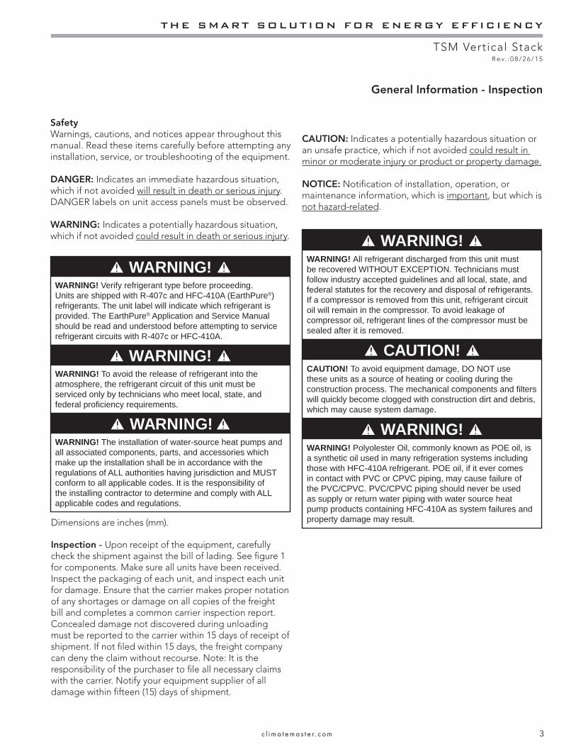
SafetyWarnings, cautions, and notices appear throughout this manual. Read these items carefully before attempting any installation, service, or troubleshooting of the equipment.
DANGER: Indicates an immediate hazardous situation, which if not avoided will result in death or serious injury. DANGER labels on unit access panels must be observed.
WARNING: Indicates a potentially hazardous situation, which if not avoided could result in death or serious injury.
CAUTION: Indicates a potentially hazardous situation or an unsafe practice, which if not avoided could result in minor or moderate injury or product or property damage.
NOTICE: Notifi cation of installation, operation, or maintenance information, which is important, but which is not hazard-related.
WARNING! Verify refrigerant type before proceeding. Units are shipped with R-407c and HFC-410A (EarthPure®) refrigerants. The unit label will indicate which refrigerant is provided. The EarthPure® Application and Service Manual should be read and understood before attempting to service refrigerant circuits with R-407c or HFC-410A.
WARNING! WARNING! The installation of water-source heat pumps and all associated components, parts, and accessories which make up the installation shall be in accordance with the regulations of ALL authorities having jurisdiction and MUST conform to all applicable codes. It is the responsibility of the installing contractor to determine and comply with ALL applicable codes and regulations.
Dimensions are inches (mm).
WARNING! Polyolester Oil, commonly known as POE oil, is a synthetic oil used in many refrigeration systems including those with HFC-410A refrigerant. POE oil, if it ever comes in contact with PVC or CPVC piping, may cause failure of the PVC/CPVC. PVC/CPVC piping should never be used as supply or return water piping with water source heat pump products containing HFC-410A as system failures and property damage may result.
WARNING!
Inspection - Upon receipt of the equipment, carefully check the shipment against the bill of lading. See fi gure 1 for components. Make sure all units have been received. Inspect the packaging of each unit, and inspect each unit for damage. Ensure that the carrier makes proper notation of any shortages or damage on all copies of the freight bill and completes a common carrier inspection report. Concealed damage not discovered during unloading must be reported to the carrier within 15 days of receipt of shipment. If not fi led within 15 days, the freight company can deny the claim without recourse. Note: It is the responsibility of the purchaser to fi le all necessary claims with the carrier. Notify your equipment supplier of all damage within fi fteen (15) days of shipment.

CLIMATEMASTER WATER-SOURCE HEAT PUMPS
TSM Vertical StackR e v. : 0 8 / 2 6 / 1 5
4 C l i m a t e M a s t e r Wa t e r - S o u r c e H e a t P u m p s
TSM Model Nomenclature - Cabinet
Cabinet
0
S.S. DRAIN PANOPTION
AB
BREAKERDISCONNECT SWITCHOPTION
0 NO OPTIONS
2
GVolt/Hertz/PhazeOPTION
208/230/60/1
123
E 265/60/1
SUPPLY
DRAIN
RETURN
BACK
FRONT
RIGHT
SUPPLY
RETURN
DRAIN
BACK
LEFT
FRONT
RIGHT
SUPPLYRETURN
DRAIN
BACK
LEFT
FRONT
RIGHT
SUPPLYRETURN
34
SUPPLY
DRAIN
RETURN
BACK
LEFT
FRONT
SUPPLY
RETURN
ISP / BREAKER
C
ABC
1
1”1”1”1”2”2”2”2”
45
DISCHARGE OPENINGS BY UNIT SIZE 88”UNIT SIZE Back, Front & Side09 thru 18 12” x 6” & 12” x 12”24 thru 42 16” x 8” & 16” x 16”
Top12” x 12”16” x 16”
DISCHARGE OPENINGS BY UNIT SIZE 80”UNIT SIZE Front09 thru 18 12” x 6”24 thru 42 16” x 6”
Top12” x 12”16” x 16”
Back & Side12” x 6” & 12” x 12”16” x 6” & 16” x 12”
OPTION DIGIT 9OPTION
0 = SLAVE/NONE1 = STANDARD2 = MASTER
0, 6
1, 2, 3 , 4, 5
DIGIT 10OPTION0
OPTION
0 = NONE
2 = LEFT BACK3 = RIGHT BACK
VERTICALPKG
NO
YES
HORIZONTALPKG
4 = LEFT SIDE5 = RIGHT SIDE
YES
YES
NO
NO
YES
NO
NO
YES
OPTION
BCDEFGHJ
A0
KLM
DISCHARGE C-SERIES80”
TSM
NO
YES
C-SERIES88”
TSM
NPQRS
NONEBACK SMALLBACK LARGEFRONT SMALLFRONT LARGETOPBACK SMALL & TOPBACK LARGE & TOPFRONT SMALL & TOPFRONT LARGE & TOP
UNIT SIZE09-18 TOP
UNIT SIZE24-36 TOP
N/A
12 X 12 16 X 16
N/A
12 X 12 16 X 16
YES
NOYESNONOYESYESNONOYES
YES
ABCD
88”80”OPTION ISO PAD65”
OPTION
BCDEFGH
A0
DISCHARGE
NONERIGHT SMALLRIGHT LARGELEFT SMALLLEFT LARGE
NO NO
NONO
NO
NO
NO
NO
YES YESYES
YESYES
YES
YES
YES
NO
NO
NO
NO
NO NO
NO
YESYES
YES
YES
YES
NONO
NONO
NO
NOYES
YES
YESYES YES
OPTION
CDLMNPRS
S=SURFACER =REMOTE
W = WALL SENSORA = ADA
BA
YESNO
PSCSTANDARD
YES
NOYESNO
YESYES
NO
ECM(DXM2 ONLY)
NOYESNO
YESNOYESNONOYESYES
A
W
RSRS
M = MPCL = LON
NO
MMLL
NO
1 1NG 0A 0 0 0 0 B 2 83 5 7 10 11 12 13 14 15
0 = STANDARDSTANDARDA, B, C etc.... = SPECIAL 1, 2, 3 etc....
REVISION LEVEL04
06
B = CURRENT REVISION
OPTIONS
POWER TERMINATION
VOLTAGE
RISER: Riser Chase0 = None
09
T-STAT WHIP
1 = 15’ whip0 = No Whip
PREMIUM SEAL
{RETURN AIR}
{RETURN AIR}
{RETURN AIR}
2 = 25’ whip3 = 35’ whip
{RETURN AIR}
DIGIT 9 - 2
DIGIT 9 - 3
DIGIT 9 - 4
DIGIT 9 - 5
C 1
FILTER SIZE
2 = Chase
RISER STYLE OPTIONS
RISER LOCATION/PACKAGING OPTIONS
BACK/FRONT/TOP DISCHARGE OPTIONS
BACK SMALL & FRONT SMALL
BACK LARGE & FRONT LARGEBACK SMALL & FRONT LARGEBACK LARGE & FRONT SMALLBACK SMALL & FRONT SMALL W/TOPBACK LARGE & FRONT LARGE W/TOPBACK SMALL & FRONT LARGE W/TOPBACK LARGE & FRONT SMALL W/TOP
CABINET HEIGHT
SIDE DISCHARGE OPTIONS
RIGHT SMALL & LEFT SMALLRIGHT LARGE & LEFT LARGERIGHT SMALL & LEFT LARGERIGHT LARGE & LEFT SMALL
HARNESS CONTROLS
ALL OPTIONS AVAILABLE
1 = 092 = 12
4 = 185 = 246 = 307 = 36
UNIT SIZE
3 = 15
SERIESTranquility High Rise Cabinet for TSM
1 = SHIPPED SEPERATELY
6 = CHASSIS SHIPPED IN CABINET
VALVE ASM QTY 2SHIPPED IN CABINET
VALVE ASM QTY 2SHIPPED W/RISERS
THE SMART SOLUTION FOR ENERGY EFFICIENCY
TSM Vertical StackR e v. : 0 8 / 2 6 / 1 5
5c l i m a t e m a s t e r . c o m
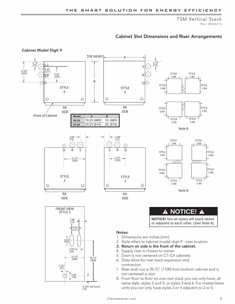
Cabinet Model Digit 9
Cabinet Slot Dimensions and Riser Arrangements
3.125” (all sizes)(79)
35.75”
2.75”(70)
[908]
12.00”[305]
2.25”(57)
3.00”(76)
12.12”(308)
12.00”(305)
5.00”(127)
5.00”(127)
2.88”(73)
2.50”(64)
FRONT VIEWSTYLE 3
TOP VIEWS
2.75”(70)
9.25”(235)
S
R
B
A
D
S
R
D
RA
SIDE
STYLE
4
Front of Cabinet
STYLE
5
STYLE
3STYLE
2
RA
SIDE
RA
SIDE
Note 8
Note 8
STYLE
3 RA
STYLE
2 RA
STYLE
5 RA
STYLE
4 RA
STYLE
3 RA
STYLE
2 RA
STYLE
5 RA
STYLE
4 RA
RA
SIDE
2.88”(73)
SRD
2.88”(73)
S R D
Model A B 09-18 19.25 [489] 19 [483]
24-36 24.25 [616] 24 [610]
STYLE
5 RA
STYLE
4 RA
STYLE
3 RA
STYLE
2 RA
STYLE
5 RA
STYLE
4 RA
STYLE
3 RA
STYLE
2 RA
9.25”(235)
12.12”(308)
NOTICE! NOTICE! Not all styles will stack above or adjacent to each other. (See Note 8).
Notes:1. Dimensions are inches [mm].2. Style refers to cabinet model digit 9 - riser location.3. Return air side is the front of the cabinet. 4. Supply riser is closest to corner.5. Drain is not centered on C1–C4 cabinets.6. Slots allow for riser stack expansion and
contraction. 7. Riser stub out is 39.75" (1100) from bottom cabinet and is
not centered in slot.8. From fl oor to fl oor on one riser stack you can only have; all
same style, styles 2 and 5; or styles 3 and 4. For master/slave units you can only have styles 3 or 4 adjacent to 2 or 5.
CLIMATEMASTER WATER-SOURCE HEAT PUMPS
TSM Vertical StackR e v. : 0 8 / 2 6 / 1 5
6 C l i m a t e M a s t e r Wa t e r - S o u r c e H e a t P u m p s
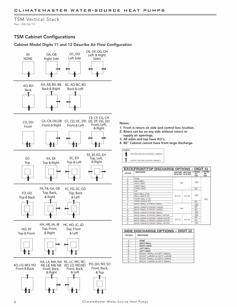
= RETURN AIR (AIR ENTERING CABINET)
= SUPPLY AIR (AIR LEAVING CABINET)
LEGEND
00
NONEOA, OB
Right Side
OC, OD
Left Side
OE, OF, OG, OHLeft & Right
Sides
AO, BO
Back
AA, AB, BA, BB
Back & RightAC, AD, BC, BD
Back & Left
EO
TopEA, EB
Top & Right
EC, ED
Top & Left
EE, EF, EG, EHTop, Left, & Right
FO, GO
Top & Back
FA, FB, GA, GB
Top, Back,
& Right
FC, FD, GC, GD
Top, Back
& Left
HO, JO
Top & Front
HA, HB, JA, JB
Top, Front,
& Right
HC, HD, JC, JD
Top, Front
& Left
CO, DO
Front
CA, CB, DA,DB
Front & RightCC, CD, DC, DD
Front & Left
CE, CF, CG, CHDE, DF, DG, DH
Front, Left, & Right
KC, LC, MC, NC,KD, LD, MD,ND
Front, Back, & Left
KA, LA, MA, NAKB, LB, MB, NB
Front, Back, & Right
KO, LO, MO, NOFront & Back
PO, QO, RO, SO
Front, Back,
& Top
1. Front is return air side and control box location.2. Risers can be on any side without return or
supply air openings.3. All sides and top have KO's.4. 80" Cabinet cannot have front large discharge.
Notes:
OPTIO N
BCDEFGH
A0
DISCHARGE
NONERIGHT SMALLRIGHT LARGELEFT SMALLLEFT LARGE
SIDE DISCHARGE OPTIONS
RIGHT SMALL & LEFT SMALLRIGHT LARGE & LEFT LARGERIGHT SMALL & LEFT LARGERIGHT LARGE & LEFT SMALL
– DIGIT 12
OPTION
BCDEFGHJ
A0
KLM
DISCHARGE C-SERIES80”
TSM
NO
YES
C-SERIES88”
TSM
NPQRS
NONEBACK SMALLBACK LARGEFRONT SMALLFRONT LARGETOPBACK SMALL & TOPBACK LARGE & TOPFRONT SMALL & TOPFRONT LARGE & TOP
UNIT SIZE09-18 TOP
UNIT SIZE24-36 TOP
N/A
12 X 12 16 X 16
N/A
12 X 12 16 X 16
YES
NOYESNONOYESYESNONOYES
YES
BACK/FRONT/TOP DISCHARGE OPTIONS
BACK SMALL & FRONT SMALL
BACK LARGE & FRONT LARGEBACK SMALL & FRONT LARGEBACK LARGE & FRONT SMALLBACK SMALL & FRONT SMALL W/TOPBACK LARGE & FRONT LARGE W/TOPBACK SMALL & FRONT LARGE W/TOPBACK LARGE & FRONT SMALL W/TOP
– DIGIT 11
TSM Cabinet Confi gurations
Cabinet Model Digits 11 and 12 Describe Air Flow Confi guration
THE SMART SOLUTION FOR ENERGY EFFICIENCY
TSM Vertical StackR e v. : 0 8 / 2 6 / 1 5
7c l i m a t e m a s t e r . c o m
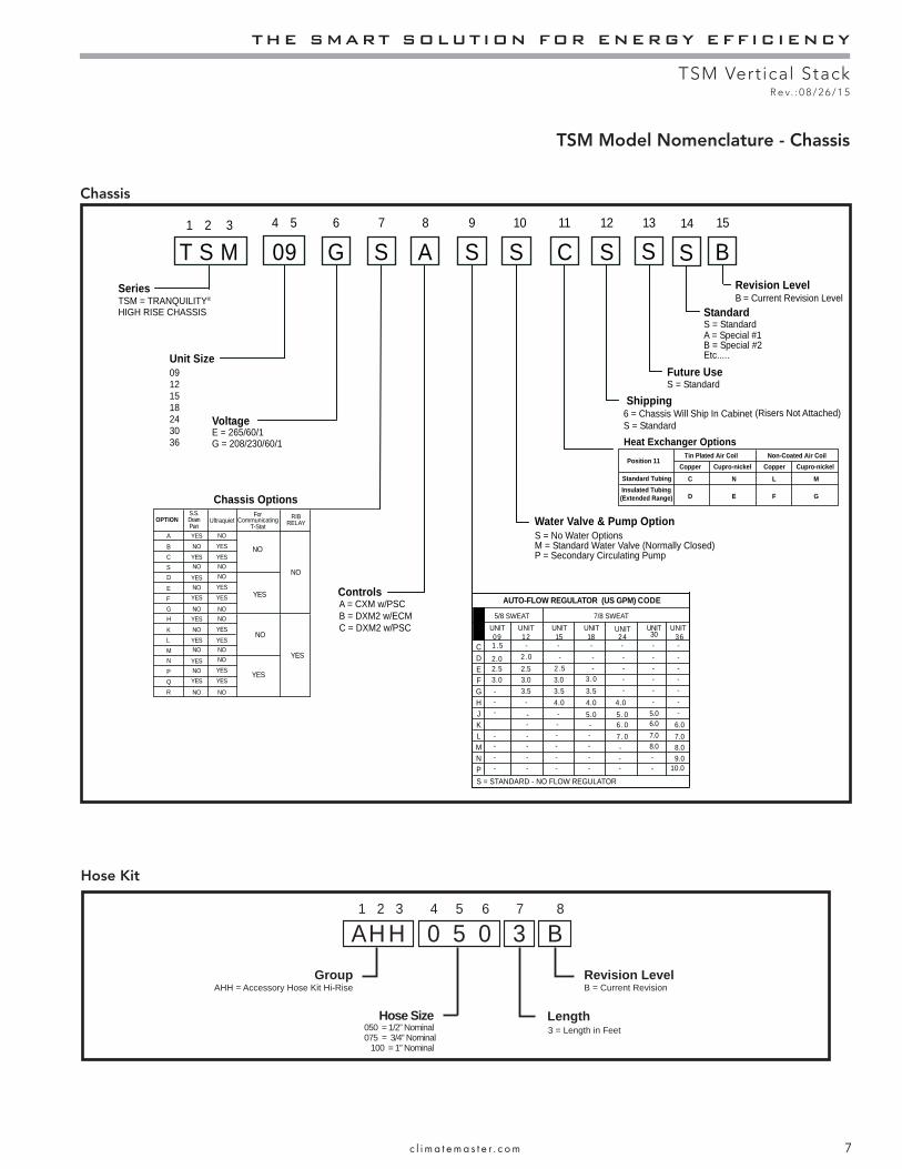
TSM Model Nomenclature - Chassis
Chassis
TSM = TRANQUILITY®
T S M1 2 3
09121518243036
09 GSeries
Unit Size
Voltage
S S S C S S4 5 6 7 9 10 11 12 13
Water Valve & Pump OptionS = No Water OptionsM = Standard Water Valve (Normally Closed)P = Secondary Circulating Pump
Shipping
Future Use
Heat Exchanger Options
HIGH RISE CHASSIS
Chassis Options
A8
Controls
S B14 15
StandardS = Standard
Revision LevelB = Current Revision Level
6 = Chassis Will Ship In CabinetS = Standard
S = Standard
7/8 SWEAT
3.02.52.0
UNIT09
E
HGF
AUTO-FLOW REGULATOR (US GPM) CODE
DC
5/8 SWEAT
4.03.5
UNIT18
2.5
-3.53.0
UNIT12
UNIT24
UNIT30
UNIT36
K
PNML
-
--
7 . 06 . 0
8.0
--
7.06.0
J 5.0- 5 . 0 5.06.0
8.09.0
7.0
S = STANDARD - NO FLOW REGULATOR
-
-
4.03.5
UNIT15
--
-
3.0
4.0
1.5 - - - - - -2 .0 - - - - -
2 .5 - - - -3 .0 - - -
- - -- -
-
- - - - -- - - -- - - -- -
--
-
10.0
A = Special #1B = Special #2Etc.....
E = 265/60/1G = 208/230/60/1
A = CXM w/PSCB = DXM2 w/ECMC = DXM2 w/PSC
Position 11Copper
C
D E
N L
F G
M
Cupro-nickel Cupro-nickelCopperStandard Tubing
Tin Plated Air Coil Non-Coated Air Coil
Insulated Tubing(Extended Range)
(Risers Not Attached)
OPTIONS.S.DrainPan
BCS
A
Ultraquiet
NOYES
EFG
D
CommunicatingT-Stat
For
NONO
NONO
NO
NO
NOYES
YES
YES
YES
YES
YESYES
RIBRELAY
NO
KLM
H NOYES
PQR
N
NONO
NONO
NO
NO
NOYES
YES
YES
YES
YES
YESYES
YES
NO
YES
NO
YES
0 5 0A H H B31 2 3 4 5 6 8
GroupAHH = Accessory Hose Kit Hi-Rise
Hose Size050 = 1/2” Nominal
Length
Revision Level
7
075 = 3/4” Nominal100 = 1” Nominal
B = Current Revision
3 = Length in Feet
Hose Kit
CLIMATEMASTER WATER-SOURCE HEAT PUMPS
TSM Vertical StackR e v. : 0 8 / 2 6 / 1 5
8 C l i m a t e M a s t e r Wa t e r - S o u r c e H e a t P u m p s
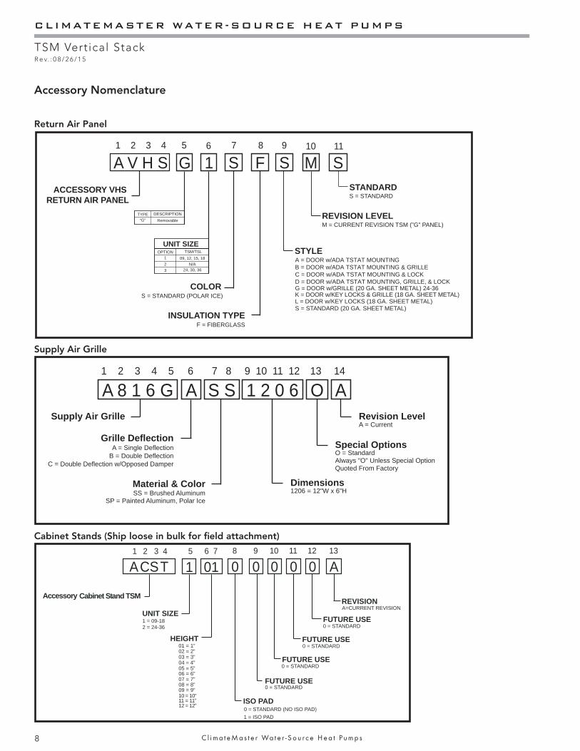
Accessory Nomenclature
A 8 1 6 G A 1 2 0 6S S1 2 3 4 5 9 10 11 127 8
Supply Air Grille
Material & Color Dimensions
C = Double Deflection w/Opposed Damper
Grille Deflection
SS = Brushed Aluminum
A = Single DeflectionB = Double Deflection
6
1206 = 12"W x 6"H
SP = Painted Aluminum, Polar Ice
O13
Special OptionsO = StandardAlways "O" Unless Special OptionQuoted From Factory
A14
Revision LevelA = Current
15
Accessory Cabinet Stand TSM
017
08
010
09
UNIT SIZE
ACST1 2 3 4
ISO PAD
FUTURE USE
FUTURE USE
011
012
A13
FUTURE USE
FUTURE USE
REVISION
HEIGHT
6
1 = 09-182 = 24-36
01 = 1”
03 = 3”02 = 2”
04 = 4”05 = 5”06 = 6”07 = 7”08 = 8”09 = 9”10 = 10”11 = 11”12 = 12”
0 = STANDARD
0 = STANDARD (NO ISO PAD)1 = ISO PAD
0 = STANDARD
0 = STANDARD
0 = STANDARD
A=CURRENT REVISION
Return Air Panel
Supply Air Grille
Cabinet Stands (Ship loose in bulk for fi eld attachment)
A V H S 1 S F S S1 2 3 4 6 7 8 9 11
ACCESSORY VHS RETURN AIR PANEL
COLOR
INSULATION TYPE
STYLE
REVISION LEVEL
S = STANDARD (20 GA. SHEET METAL)
A = DOOR w/ADA TSTAT MOUNTINGB = DOOR w/ADA TSTAT MOUNTING & GRILLEC = DOOR w/ADA TSTAT MOUNTING & LOCKD = DOOR w/ADA TSTAT MOUNTING, GRILLE, & LOCK
L = DOOR w/KEY LOCKS (18 GA. SHEET METAL)
G = DOOR w/GRILLE (20 GA. SHEET METAL) 24-36
M10
STANDARDS = STANDARD
UNIT SIZEOPTION
123
K = DOOR w/KEY LOCKS & GRILLE (18 GA. SHEET METAL)S = STANDARD (POLAR ICE)
F = FIBERGLASS
TSM/TSL09, 12, 15, 18
M = CURRENT REVISION TSM (”G” PANEL)
24, 30, 36N/A
TYPE“G”
DESCRIPTIONRemovable
G5
THE SMART SOLUTION FOR ENERGY EFFICIENCY
TSM Vertical StackR e v. : 0 8 / 2 6 / 1 5
9c l i m a t e m a s t e r . c o m
Storage - Equipment should be stored in its original packaging in a clean, dry area. Store chassis in an upright position at all times. Stack units at a maximum of 2 units high.
Store cabinets how they were shipped - horizontal or vertical, keeping them on their pallets for protection. Do not stack multipacks. Cabinets with risers, stack a maximum of 4 high.
Unit Protection - Cover units on the job site with either the original packaging or an equivalent protective covering. Cap the open ends of pipes stored on the job site. In areas where painting, plastering, and/or spraying has not been completed, all due precautions must be taken to avoid physical damage to the units and contamination by foreign material. All openings in cabinet must be covered during all stages of construction. Physical damage and contamination may prevent proper start-up and may result in costly equipment clean-up.
Examine all pipes, fi ttings, and valves before installing any of the system components. Remove any dirt or debris found in or on these components.
Prior to fl ushing risers with water, be sure that the temperature in building will always be above freezing.
Pre-Installation - Installation, Operation, and Maintenance instructions are provided with each unit. The installation site chosen should include adequate service clearance around the unit. Before unit installation and start-up, read all manuals and become familiar with the unit and its operation. Thoroughly check the system before operation. Your installation may require additional, different sequence, or modifi cation to steps in this IOM.
Prepare cabinet for installation as follows:1. Compare the electrical data on the unit nameplate
with ordering and shipping information to verify that the correct unit has been shipped.
2. Each cabinet has a tag to indicate the location to be installed and the riser diameter.
3. Keep the cabinet openings and exposed sheet metal covered until installation is complete and all plastering, painting, etc. is fi nished and cleaned.
4. Inspect all electrical connections. Connections must be clean and tight at the terminals.
5. Confi gure supply air openings - remove knockouts
(K.O.), cut insulation, assemble duct angles with short fl ange inside cabinet. See model number digits 11 and 12 and Supply Air Grille from schedule, use confi gurations on page 6. Do not remove extra K.O.’s - must securely cover any open unused K.O.’s.
6. For cabinets without risers - remove correct riser knockouts, slit insulation vertical down center of slot (do not remove).
7. Repair any torn insulation with foil tape.8. A base vibration dampening pad is recommended to
help eliminate transfer of vibration to the structure. If isolation pad was not ordered, obtain of 0.070” to 0.125” (1.5 to 3) thick pad and apply to the perimeter of the cabinet base.
9. For chassis shipped inside cabinet remove and discard 4 shipping bolts.
10. Remove inner panel (8 screws) and save for reinstallation after chassis is installed.
11. For standard cabinets remove and discard condensate pan shipping wire ties.
12. If risers are attached to cabinet, Lift pan approximately 2” to check drain hose is attached and clamped to pan and riser stub.
Prepare chassis for installation as follows:1. Verify refrigerant tubing is free of kinks or dents and
that it does not touch other tubes or unit parts as it passes over or through. Adjust if needed and separate with closed cell insulation.
2. Inspect all electrical connections. Connections must be clean and tight at the terminals.
3. If chassis is not installed in cabinet, store in original carton in a clean and dry location.
CAUTION! DO NOT store or install units in corrosive environments or in locations subject to temperature or humidity extremes (e.g., attics, garages, rooftops, etc.). Corrosive conditions and high temperature or humidity can signifi cantly reduce performance, reliability, and service life. Always move and store units in an upright position. Tilting units on their sides may cause equipment damage.
CAUTION!
CAUTION! CAUTION! CUT HAZARD - Failure to follow this caution may result in personal injury. Sheet metal parts may have sharp edges or burrs. Use care and wear appropriate protective clothing, safety glasses and gloves when handling parts and servicing heat pumps.
Pre-Installation Information
CLIMATEMASTER WATER-SOURCE HEAT PUMPS
TSM Vertical StackR e v. : 0 8 / 2 6 / 1 5
10 C l i m a t e M a s t e r Wa t e r - S o u r c e H e a t P u m p s
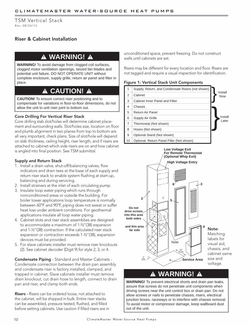
1 Supply, Return, and Condensate Risers (not shown) } 2 Cabinet
3 Cabinet Inner Panel and Filter
4 Chassis }5 Return Air Panel
6 Supply Air Grille
7 Thermostat (Not shown)
8 Hoses (Not shown)
9 Optional Stand (Not shown)
10 Optional Return Panel Filler (Not shown)
Core Drilling For Vertical Riser StackCore drilling slab slot/holes will determine cabinet place-ment and surrounding walls. Slot/holes size, location on fl oor and plumb alignment in two planes from top to bottom are all very important, check plans. Size of slot/hole will depend on slab thickness, ceiling height, riser length, and if risers are attached to cabinet-which side risers are on and how cabinet is angled into fi nal position. See TSM submittal.
Supply and Return Stack1. Install a drain valve, shut-off/balancing valves, fl ow
indicators and drain tees at the base of each supply and return riser stack to enable system fl ushing at start-up, balancing and during servicing.
2. Install strainers at the inlet of each circulating pump.3. Insulate loop water piping which runs through
nonconditioned areas or outside the building. For boiler tower applications loop temperature is normally between 60°F and 90°F, piping does not sweat or suffer heat loss under ambient conditions. For geothermal applications insulate all loop water piping.
4. Cabinet slots and riser stack assemblies are designed to accommodate a maximum of 1-½”(38) expansion and 1-½”(38) contraction. If the calculated riser stack expansion or contraction exceeds 1-½”(38), expansion devices must be provided.
5. For slave cabinets installer must remove riser knockouts (2). See cabinet decoder (Digit 9) for style 2, 3, or 4.
Condensate Piping - Standard and Master Cabinets - Condensate connection between the drain pan assembly and condensate riser is factory installed, clamped, and trapped in cabinet. Slave cabinets installer must remove drain knockout, cut drain hose to length, connect to drain pan and riser, and clamp both ends.
Risers - Risers can be ordered loose, not attached to the cabinet, will be shipped in bulk. Entire riser stacks can be assembled, pressure tested, fl ushed, and fi lled before setting cabinets. Use caution if fi lled risers are in
Riser & Cabinet Installation
CAUTION! CAUTION! To ensure correct riser positioning and to compensate for variations in fl oor-to-fl oor dimensions, do not allow the unit to unit riser joint to bottom out.
WARNING! WARNING! To avoid damage from clogged coil surfaces, clogged motor ventilation openings, seized fan blades and potential unit failure, DO NOT OPERATE UNIT without complete enclosure, supply grille, return air panel and fi lter in place.
5
3
Low Voltage ExitFor Remote Thermostat(Optional Whip Exit)
2
6
High Voltage Entry
4
Do not drive screws into this area
both sides
Service Area
Note
24” (610)
2”(50)
and this area far side
WARNING! WARNING! To prevent electrical shorts and drain pan leaks, assure that screws do not penetrate unit components when driving screws near the unit control box or drain pan. Do not allow screws or nails to penetrate chassis, risers, electrical junction boxes, raceways or to interfere with chassis removal. To avoid motor or compressor damage, keep wallboard dust out of the unit.
Figure 1: Vertical Stack Unit Components
unconditioned space, prevent freezing. Do not construct walls until cabinets are set.
Risers may be different for every location and fl oor. Risers are not tagged and require a visual inspection for identifi cation.
Install Now
Install Later
Note:Matching labels for visual aid, chassis, and cabinet same size and voltage.
THE SMART SOLUTION FOR ENERGY EFFICIENCY
TSM Vertical StackR e v. : 0 8 / 2 6 / 1 5
11c l i m a t e m a s t e r . c o m
Before brazing check building plans to be sure you are installing correct riser; Description of riser, diameter, type, and shutoff size are all variations. See fi gure 2 for help in identifying riser and dimension to set riser runout. Note dimension is from bottom of cabinet, add if stand or thick isolation pads are used to get correct dimension from fl oor.
Description- Supply and return risers can be straight, transition up, transition down, bottom capped, or top capped. Drain risers can be straight, transition up, or top capped. All drain risers and extended range (operation below 60 ºF entering water temperature) supply and return risers need insulation.
Riser Diameter (nominal water size)- 1”, 1.25”, 1.50”, 2”, 2.5”, 3”. Top of riser and bottom of riser on fl oor above must be same diameter.
Type M has red identifi cation marking (stripe running down the tube) and Type L (thicker wall) has blue identifi cation marking. If tube is insulated pull back carefully to check color.
Shutoff size (nominal FPT for hose connection) for cabinet/chassis- ½” for C1 (09) and C2 (12); ¾” for C3 (15) and C4 (18); 1” for C5 (24), C6 (30), and C7 (36).
Supply riser is always closest to back corner of cabinet, return riser next, and drain riser in approx. middle of the cabinet. Risers are 9.25” (235) apart on centerline. See Figure 2 & 3.
Secure Riser Stack to building structure so stack does not drop over time. Cabinet slots allow for 1.50” (38mm) maxi-mum expansion and 1.50” (38mm) maximum contraction, use expansion devices if you exceed these values, and between clamps.
NOTICE: Any risers misplaced, assembled in wrong location, brazed incorrect, modifi ed incorrect (including cutting off or extending), runoff at incorrect height, misalignment found anytime including when cabinets are set, not using expansion devices if specifi ed, or stack was not supported correctly is the sole responsibility of the installing contractor.
Cabinet Installation When Risers are Attached (See Fig. 2)1. Check plans that cabinet is correct for location, cabinet
will have tag and data plate with information, including unit size, diameters of risers, and electrical data. Move cabinet close to slab slot, do not carry cabinet using risers, always use 2 people.
2. Check risers are 3” above the top of cabinet. If not loosen straps, adjust riser and retighten.
3. Confi gure supply air openings and attach angles. See Pre-Installation. If optional stand is required attach to bottom of cabinet with 4 screws.
4. Start on lowest fl oor, lift cabinet and angle so risers pass through slab slot/holes until cabinet is standing up and setting on fl oor. Be careful not to damage either end of riser, do not carry cabinet using risers. Move cabinet until risers are centered in slot/holes and cabinet sides are square with proposed walls. If extensions are used, assemble to risers on lower fl oor. Mark set depth in case they drop before brazing. Dimension should be 1” to 2”. Less than 1” or more than 2-1/2” is not acceptable. Extensions should never bottom in swedge of riser. Note: Riser joints should be well below slab for brazing/inspection.
5. Attach the cabinet assembly to the fl oor on at least two sides using sheet metal angles. Additional anchorage may be provided by installing brackets at the top of the cabinet.
6. DO NOT attach drywall studs to cabinet. When all units on a riser are anchored into place, complete riser joints as follows:
a. Verify that all riser joints are vertically aligned and that risers penetrate 1” to 2” (25 to 50) into the swaged joint of the riser below. DO NOT let riser joint bottom out.
b. Braze riser joints with a high-temperature alloy (such as Phos-copper or Silfos). Soft solder (50-50, 60-40 or 85-15) or low-temperature alloys are NOT suitable for this application.
c. Must securely anchor riser stacks to the building structure with at least one contact point. Typically at middle fl oors as needed. Example 40 fl oor, anchor at 10, 20, and 30. To accommodate vertical expansion and contraction use expansion devices between anchors. DO NOT fasten risers rigidly within the unit.
d. Verify that unit shut-off valves are closed. DO NOT OPEN VALVES until the system has been cleaned and fl ushed.
e. Pressure check riser - locate and repair leaks.f. If cabinet is slave, make sure P-Trap Hose is
connected and clamped to riser stub and condensate pan. Suggest running copper stub into slave cabinet, cut hose to length, clamp inside cabinet for future access. If condensate hose must be rotated, loosen clamp on pan, rotate, and reclamp. Check condensate drain - clean pan if needed. Slowly pour 1 to 2 quarts (1 to 2 liters) of water into pan. Water should drain freely. Check for water in cabinet and on fl oor. Repair if needed.
g. Repair or replace any damaged or missing
CLIMATEMASTER WATER-SOURCE HEAT PUMPS
TSM Vertical StackR e v. : 0 8 / 2 6 / 1 5
12 C l i m a t e M a s t e r Wa t e r - S o u r c e H e a t P u m p s
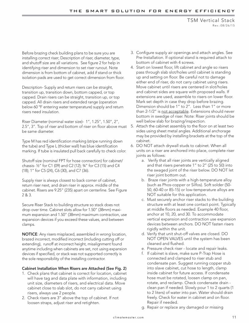
Shipped Horizontal(All ClimateMaster
Thermostats)Vertical
2 x 4 Junction Boxinsulation on risers, and extensions (if used).h. To facilitate cleaning and fl ushing, install the
hose kit at the end farthest from the pump and connect the ends of the hoses with the riser fl ush adapter (Kit - AFL5751). Then open both valves before pumping fresh water through the system, close the valves when the system is clean. Remove the fl ush adapter before installing the chassis.
Note: Refer to System Flushing Section of this manual for more information.
i. Install air vents in piping loop at highest accessible point as required to bleed the system of air accumulated during installation.
7. Next fl oor up select correct unit. Suggest measuring from top of slab to top of riser below. Now measure from bottom of cabinet (or stand/pad if used) to bottom of riser, this dimension should be 1” to 2”more than fi rst measurement. Less than 1” or more than 2-1/2” is not acceptable. Risers should never bottom in swedge below. Cut riser or extension if needed. DO NOT slide riser up or down on cabinet. Repeat steps 2-5.
Cabinet Installation when risers separate: See riser and cabinet sections in TSL Submittal 97B0116N01.
Optional Frame for Return Air Panel - Position studs in front of cabinet and install frame in opening. Seal the gap between the cabinet and the frame. If fresh air motorized damper assembly is used, fi eld fabricate and install duct from outside to frame opening. Assembly is installed later. See instructions with assembly. NOTICE! Allow for drywall thickness under frame front fl ange.
Optional Field Supplied Duct Installation - When return air is required to enter the unit through openings in a stud wall, supply and fi eld install an optional duct. Seal duct against the return air grille. Add a blockoff above and below the chassis to ensure that all air entering the unit passes through the fi lter and refrigerant-to-air coil. Sheet metal ductwork must not be attached to the cabinet. A canvas type fl exible connection should be used between the cabinet and the ductwork.
When supply air is ducted from unit, sheet metal ductwork
must not be attached to the cabinet. A canvas-type fl exible connection should be used between the cabinet and the ductwork.
Drywall Installation: If you have the surface mounted thermostat option (cabinet model digit 5 = P or S), make sure before you install the drywall that the 2x4 junction box is in the correct orientation. Turn if needed. Check your thermostat.
For best sound attenuation, it is recommended not to attach drywall to cabinet.
Install studs and drywall using conventional construction methods. Secure drywall to studs with low profi le, pan-head sheet metal screws. Drywall must not be fastened to drain pan edges or control box enclosure. Drywall can be attached directly to cabinet (except in places indicated in Figure 1), front of cabinet requires double thickness. Do not attach drywall studs to cabinet. Do not install drywall using adhesive alone.
See typical construction fi gures 4, 5, and 6 to determine stud layouts and dimension from cabinet to fi nished wall.Vacuum all drywall dust and construction debris from cabinet insulation, drain pans and blower discharge plenum after cutting out supply and return holes for grilles. Insulation should be placed between the drywall and the cabinet for sound attenuation.
When installation is complete, cover all cabinet openings and exposed sheet metal. (Cardboard from unit shipping cartons can be used). Do not allow paint or wall texture over-spray to contact insulation, sheet metal, coil, fan or other unit components. Warranties are void if paint or other foreign debris is allowed to contaminate internal unit components.
Do not adjust the Sight and Sound X-baffl e (see Figure 2). It is not designed to be used as a damper.
NOTICE! NOTICE! ClimateMaster is not responsible for wallboard repair if 2 x 4 box was not in correct orientation.
THE SMART SOLUTION FOR ENERGY EFFICIENCY
TSM Vertical StackR e v. : 0 8 / 2 6 / 1 5
13c l i m a t e m a s t e r . c o m
Cabinet Installation
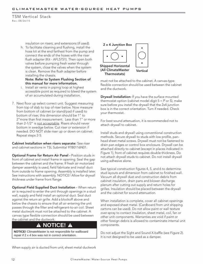
Figure 2: Cabinet
Sight and Sound Baffle
Optional ElectricHeater (Note 4)
Condensate Hose (7/8” I.D.)
Internally trapped
Control Box
Conduit ForElectrical
SIDE VIEW
WallboardFlanges Field
FabricateExtensionsIf Required
Riser Strap - Top and Bottom
Riser Shutoffs
RiserRunout
3” (76) Swage
Shipping Wire TiesRemove Before
Installing Chassis.
2.00 (54)
39.75 (1100)
3.12 (79)
Condensate (C) risers runout to be
centered in slot
and clamped at both ends
Supply (S) and Return (R) risers may have moved during shipping. Check, they must be 3” (76) above top of cabinet. Loosen straps and readjust any if needed, then re-tighten. After riser stack is completed and secured to building structure, straps can be removed.
Risers can be in 4 positions. Supply (S) riser always closest to corner.
Note: Runouts are not centered in slots.
SRCR
R SC
RC S
S
Front (Return Air Opening)
Riser location shown for Style 3 cabinet
9.25 (235)
Notes:1. For chassis shipped in cabinet remove and
discard 4 shipping bolts.2. Supply (S) and Return (R) risers may have moved
during shipping. Check, they must be 3” (76) above top of cabinet. Loosen straps and readjust any if needed, then re-tighten. After riser stack is completed and secured to building structure, straps can be removed..
3. Before installing chassis – check drain hose is connected and clamped at both ends, and drain pan is free and setting on 4 rubber grommets.
4. Optional Electric Heater – Single point power to unit.
CLIMATEMASTER WATER-SOURCE HEAT PUMPS
TSM Vertical StackR e v. : 0 8 / 2 6 / 1 5
14 C l i m a t e M a s t e r Wa t e r - S o u r c e H e a t P u m p s
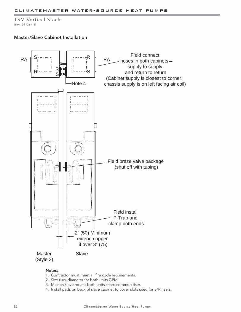
Master/Slave Cabinet Installation
2” (50) Minimum extend copper if over 3” (75)
Master(Style 3)
Slave
Note 4
RA
R R
RS
S S
RA
Field install P-Trap and
clamp both ends
Field connecthoses in both cabinets
supply to supply and return to return
(Cabinet supply is closest to corner, chassis supply is on left facing air coil)
Field braze valve package (shut off with tubing)
Notes:1. Contractor must meet all fi re code requirements.2. Size riser diameter for both units GPM.3. Master/Slave means both units share common riser.4. Install pads on back of slave cabinet to cover slots used for S/R risers.
THE SMART SOLUTION FOR ENERGY EFFICIENCY
TSM Vertical StackR e v. : 0 8 / 2 6 / 1 5
15c l i m a t e m a s t e r . c o m
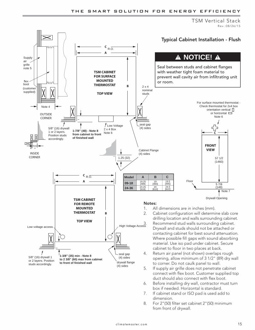
Notes:1. All dimensions are in inches (mm).2. Cabinet confi guration will determine slab core
drilling location and walls surrounding cabinet.3. Recommend stud walls surrounding cabinet.
Drywall and studs should not be attached or contacting cabinet for best sound attenuation. Where possible fi ll gaps with sound absorbing material. Use iso pad under cabinet. Secure cabinet to fl oor in two places at back.
4. Return air panel (not shown) overlaps rough opening, allow minimum of 3 1/2" (89) dry wall to corner. Do not caulk panel to wall.
5. If supply air grille does not penetrate cabinet connect with fl ex boot. Customer supplied top duct should also connect with fl ex boot.
6. Before installing dry wall, contractor must turn box if needed. Horizontal is standard.
7. If cabinet stand or ISO pad is used add to dimension.
8. For 2"(50) fi lter set cabinet 2"(50) minimum from front of drywall.
Typical Cabinet Installation - Flush
R.O.
X
19.25[489]
19[483]24
[610]24.25[616]
B19.5[495]24.5[622]
CModel
09-18
24-36
A
A
TSM CABINET FOR SURFACE
MOUNTED THERMOSTAT
TOP VIEW
OUTSIDE
CORNER
C
X
X
C5/8” (16) drywall 1 or 2 layers. Position studs accordingly.
(customer supplied)
1-7/8” (48) - Note 8from cabinet to front of finished wall
2 x 4 BoxNote 6
Supply air grille note 5
Cabinet Flange (4) sides
Floor
Note 7
Drywall Opening
5 7/8(149)
57 1/2(1460)
Note 4
1.25 (32)
seal gap (4) sides
2 x 4 nominal studs
R.O.
X
A
TSM CABINET FOR REMOTE
MOUNTED THERMOSTAT
TOP VIEW
C
X5/8” (16) drywall 1 or 2 layers. Position studs accordingly.
Low voltage access
1-3/8” (35) min - Note 8to 2 3/8” (60) max from cabinet to front of finished wall drywall flange
(4) sides
seal gap (4) sides
X X
X
X
X
B
Bflexboot
For surface mounted thermostat -Check thermostat for 2x4 box
orientation vertical or horizontal
Note 6
FRONT VIEW
INSIDE
CORNER
Note 4
Low Voltage
High Voltage Access
NOTICE! Seal between studs and cabinet fl anges with weather tight foam material to prevent wall cavity air from infi ltrating unit or room.
CLIMATEMASTER WATER-SOURCE HEAT PUMPS
TSM Vertical StackR e v. : 0 8 / 2 6 / 1 5
16 C l i m a t e M a s t e r Wa t e r - S o u r c e H e a t P u m p s
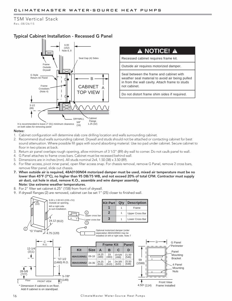
Typical Cabinet Installation - Recessed G Panel
G Style Return Air Panel
6.00(152)
Note 8, 9
DRYWALL 5/8" (16)
CABINETTOP VIEW
3-1/2(89)
It is recommended to leave 2” (51) minimum clearance on both sides for removing panel
X
Seal Gap (4) Sides
X
FrameOutsideDrywall
C
57-1/2(1460) R.O.
5-7/8*(149)Floor
48A0100N51
48A0100N52
19-5/8(498)
19(483)
24(610)
19.25(489)
24.25(616)
24-3/8(620)
09-18
24-36
Panel
CBAKit Size12-1/4(311)
28-5/8(727)
Optional motorized damper (orderseperately) 48A0100N04 may beinstalled on left or right side. Note 7
D
59(1599)
4.50* (114)Front View
Frame Installed
G Panel Perimeter
PanelMountingBracket
4 PanelMountingNuts
* Dimension if cabinet is on floor. Add if cabinet is on stand/pad.
9.00 x 2.00 KO (228 x 51)Outside air opening,
left or right sideto suit installation.
“G” Frame
24.12
.38(10)
(612)
4.75 (120)
Upper cross bar
Lower cross bar
R.O.
D21.50(546)
25.50(648)
2
3
Frame12
3
Upper Cross Bar
Lower Cross Bar
1
1
1
DescriptionKit Part Qty
1
B
A
Cabinet Flange
1.25 (32)
Frame Crossbars (Note 4)
XX
FRONT VIEW
Frame Kit
NOTICE! Recessed cabinet requires frame kit.
Outside air requires motorized damper.
Seal between the frame and cabinet with weather seal material to avoid air being pulled in from the wall cavity. Attach frame to studs not cabinet.
Do not distort frame shim sides if required.
Notes:1. Cabinet confi guration will determine slab core drilling location and walls surrounding cabinet.2. Recommend stud walls surrounding cabinet. Drywall and studs should not be attached or contacting cabinet for best
sound attenuation. Where possible fi ll gaps with sound absorbing material. Use iso pad under cabinet. Secure cabinet to fl oor in two places at back.
3. Return air panel overlaps rough opening, allow minimum of 3 1/2" (89) dry wall to corner. Do not caulk panel to wall.4. G Panel attaches to frame cross bars. Cabinet must be recessed behind wall. 5. Dimensions are in inches (mm). All studs nominal 2x4, 1.50 (38) x 3.50 (89).6. For fi lter access, pivot inner panel, open fi lter access snap. For chassis removal, remove G Panel, remove 2 cross bars,
remove fi lter panel, slide out chassis.7. When outside air is required, 48A0100N04 motorized damper must be used, mixed air temperature must be no
lower than 45°F (7°C), no higher than 95 DB/75 WB, and not exceed 20% of total CFM. Contractor must supply air duct, cut hole in stud, remove K.O., assemble and wire damper assembly. Note: Use extreme weather temperatures.
8. For 2" fi lter set cabinet 6.25" (158) from front of drywall.If drywall flanges (2) are removed, cabinet can be set 1” (25) closer to finished wall.9.
THE SMART SOLUTION FOR ENERGY EFFICIENCY
TSM Vertical StackR e v. : 0 8 / 2 6 / 1 5
17c l i m a t e m a s t e r . c o m
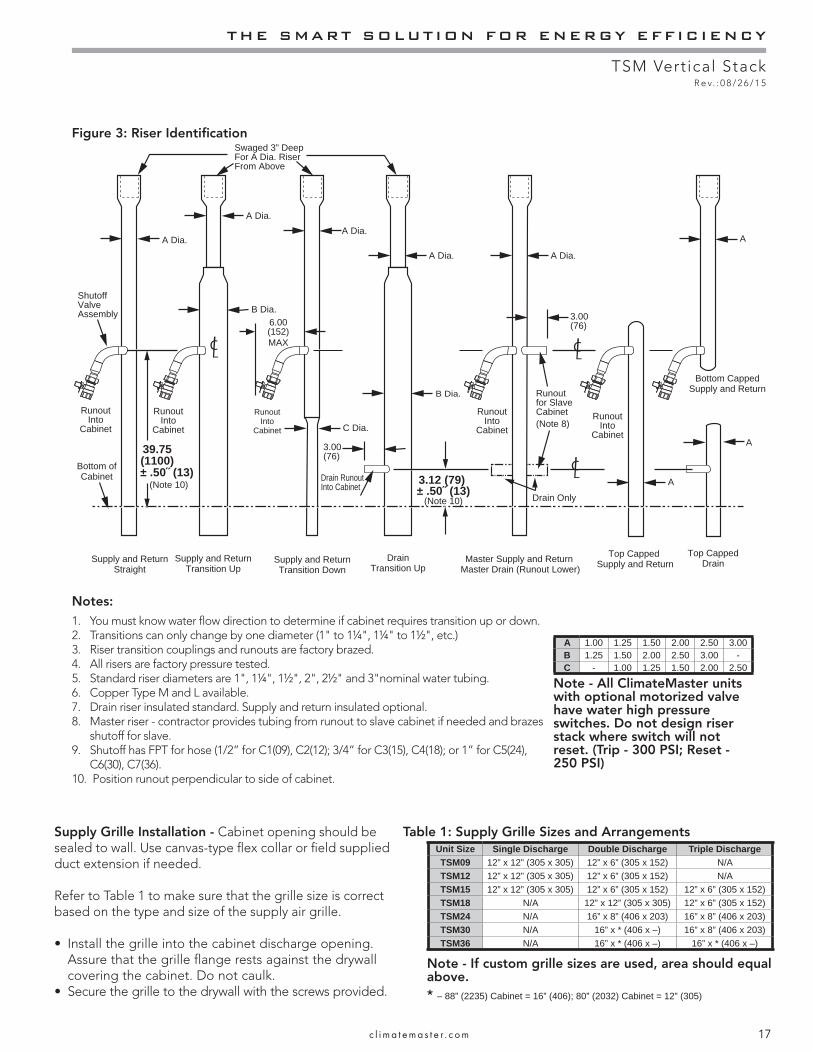
B Dia.
A Dia.
Swaged 3” DeepFor A Dia. RiserFrom Above
A Dia.
C Dia.
A Dia. A Dia.
3.00(76)6.00
(152)MAX
39.75(1100)
± .50 (13) (Note 10)
3.00(76)
3.12 (79) ± .50 (13)
(Note 10)
B Dia.
Drain RunoutInto Cabinet
Supply and ReturnTransition Up
Supply and ReturnTransition Down
DrainTransition Up
A Dia.
ShutoffValveAssembly
Supply and ReturnStraight
Master Supply and Return Master Drain (Runout Lower)
Drain Only
Top Capped Supply and Return
Top CappedDrain
Bottom CappedSupply and ReturnRunout
for SlaveCabinet Runout
IntoCabinet
RunoutInto
Cabinet
RunoutInto
Cabinet
RunoutInto
Cabinet
RunoutInto
Cabinet(Note 8)
A
A
A
Bottom of Cabinet
Table 1: Supply Grille Sizes and ArrangementsSupply Grille Installation - Cabinet opening should be sealed to wall. Use canvas-type fl ex collar or fi eld supplied duct extension if needed.
Refer to Table 1 to make sure that the grille size is correct based on the type and size of the supply air grille.
• Install the grille into the cabinet discharge opening. Assure that the grille flange rests against the drywall covering the cabinet. Do not caulk.
• Secure the grille to the drywall with the screws provided.
Unit Size Single Discharge Double Discharge Triple DischargeTSM09 12” x 12” (305 x 305) 12” x 6” (305 x 152) N/ATSM12 12” x 12” (305 x 305) 12” x 6” (305 x 152) N/ATSM15 12” x 12” (305 x 305) 12” x 6” (305 x 152) 12” x 6” (305 x 152)TSM18 N/A 12” x 12” (305 x 305) 12” x 6” (305 x 152)TSM24 N/A 16” x 8” (406 x 203) 16” x 8” (406 x 203)TSM30 N/A 16” x * (406 x –) 16” x 8” (406 x 203)TSM36 N/A 16” x * (406 x –) 16” x * (406 x –)
Notes:1. You must know water fl ow direction to determine if cabinet requires transition up or down.2. Transitions can only change by one diameter (1" to 1¼", 1¼" to 1½", etc.)3. Riser transition couplings and runouts are factory brazed.4. All risers are factory pressure tested.5. Standard riser diameters are 1", 1¼", 1½", 2", 2½" and 3"nominal water tubing.6. Copper Type M and L available.7. Drain riser insulated standard. Supply and return insulated optional.8. Master riser - contractor provides tubing from runout to slave cabinet if needed and brazes
shutoff for slave.9. Shutoff has FPT for hose (1/2” for C1(09), C2(12); 3/4” for C3(15), C4(18); or 1” for C5(24),
C6(30), C7(36).10. Position runout perpendicular to side of cabinet.
A 1.00 1.25 1.50 2.00 2.50 3.00B 1.25 1.50 2.00 2.50 3.00 -C - 1.00 1.25 1.50 2.00 2.50
Figure 3: Riser Identifi cation
Note - All ClimateMaster units with optional motorized valve have water high pressure switches. Do not design riser stack where switch will not reset. (Trip - 300 PSI; Reset - 250 PSI)
Note - If custom grille sizes are used, area should equal above.* – 88” (2235) Cabinet = 16” (406); 80” (2032) Cabinet = 12” (305)
CLIMATEMASTER WATER-SOURCE HEAT PUMPS
TSM Vertical StackR e v. : 0 8 / 2 6 / 1 5
18 C l i m a t e M a s t e r Wa t e r - S o u r c e H e a t P u m p s
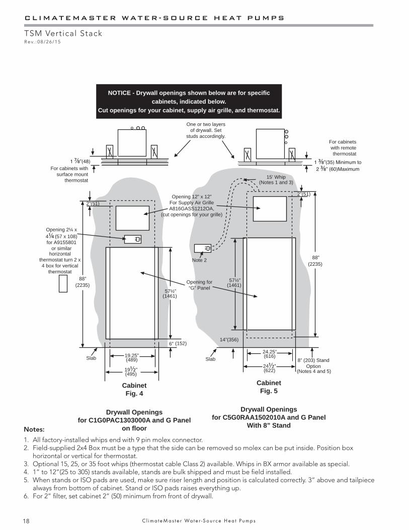
Slab
88”(2235)
(152)
(1461)
(2235)
57½”
6”
19½”(495)
19.25”(489) Slab
Opening 12” x 12”For Supply Air GrilleA816GASS1212OA,
(cut openings for your grille)
88”
8” (203) StandOption
Opening for“G” Panel
14”(356)
15' Whip
Note 2
2”(51)
2”(51)
Opening 2¼ x 4¼ (57 x 108)for A9155801
or similarhorizontal
thermostat turn 2 x 4 box for vertical
thermostat
(Notes 1 and 3)
(1461)57½”
24½”(622)
24.25”(616)
(Notes 4 and 5)
One or two layers of drywall. Set
studs accordingly.
For cabinets with surface mount
thermostat
For cabinets with remote thermostat
Notes:
1. All factory-installed whips end with 9 pin molex connector.2. Field-supplied 2x4 Box must be a type that the side can be removed so molex can be put inside. Position box
horizontal or vertical for thermostat.3. Optional 15, 25, or 35 foot whips (thermostat cable Class 2) available. Whips in BX armor available as special.4. 1” to 12”(25 to 305) stands available, stands are bulk shipped and must be fi eld installed.5. When stands or ISO pads are used, make sure riser length and position is calculated correctly. 3” above and tailpiece
always from bottom of cabinet. Stand or ISO pads raises everything up.6. For 2” fi lter, set cabinet 2” (50) minimum from front of drywall.
Drywall Openingsfor C1G0PAC1303000A and G Panel
on fl oor
CabinetFig. 4
CabinetFig. 5
Drywall Openingsfor C5G0RAA1502010A and G Panel
With 8” Stand
NOTICE - Drywall openings shown below are for specifi c cabinets, indicated below.
Cut openings for your cabinet, supply air grille, and thermostat.
THE SMART SOLUTION FOR ENERGY EFFICIENCY
TSM Vertical StackR e v. : 0 8 / 2 6 / 1 5
19c l i m a t e m a s t e r . c o m
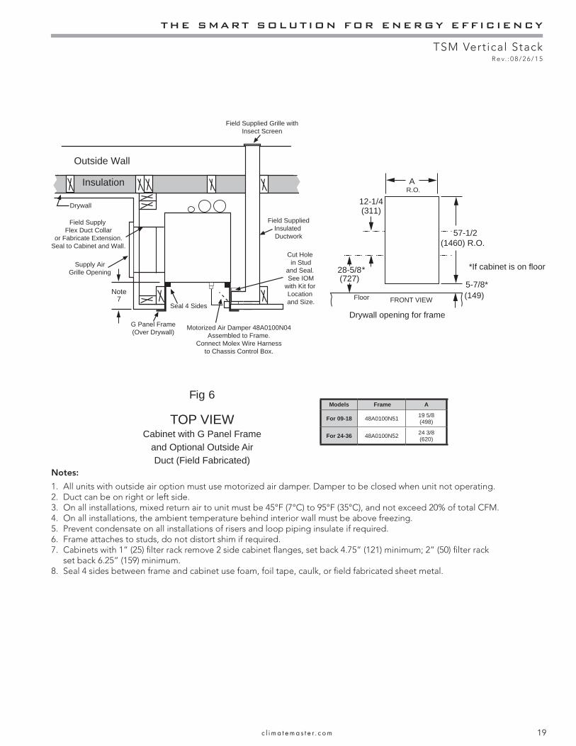
Outside Wall
Insulation
Field SuppliedInsulated Ductwork
Field Supplied Grille withInsect Screen
Field Supply Flex Duct Collar
or Fabricate Extension.Seal to Cabinet and Wall.
G Panel Frame(Over Drywall)
Seal 4 Sides
Motorized Air Damper 48A0100N04Assembled to Frame.
Connect Molex Wire Harnessto Chassis Control Box.
Cut Hole in Stud
and Seal. See IOM
with Kit for Location and Size.
Drywall
Supply AirGrille Opening
A
Note7
57-1/2(1460) R.O.
5-7/8*(149)Floor
12-1/4(311)
28-5/8(727)
*If cabinet is on floor
Drywall opening for frame
R.O.
FRONT VIEW
*
Models Frame A
For 09-18 48A0100N51 19 5/8 (498)
For 24-36 48A0100N52 24 3/8 (620)
Notes:
1. All units with outside air option must use motorized air damper. Damper to be closed when unit not operating.2. Duct can be on right or left side.3. On all installations, mixed return air to unit must be 45°F (7°C) to 95°F (35°C), and not exceed 20% of total CFM.4. On all installations, the ambient temperature behind interior wall must be above freezing.5. Prevent condensate on all installations of risers and loop piping insulate if required.6. Frame attaches to studs, do not distort shim if required.7. Cabinets with 1” (25) filter rack remove 2 side cabinet flanges, set back 4.75” (121) minimum; 2” (50) filter rack
set back 6.25” (159) minimum. 8. Seal 4 sides between frame and cabinet use foam, foil tape, caulk, or field fabricated sheet metal.
Fig 6
TOP VIEWCabinet with G Panel Frame
and Optional Outside AirDuct (Field Fabricated)
CLIMATEMASTER WATER-SOURCE HEAT PUMPS
TSM Vertical StackR e v. : 0 8 / 2 6 / 1 5
20 C l i m a t e M a s t e r Wa t e r - S o u r c e H e a t P u m p s
Commercial Water Loop Applications - Commercial systems typically include a number of units connected to a common piping system with a cooling tower and boiler. Any unit plumbing maintenance work can introduce air into the piping system; therefore air elimination equipment is a major portion of the mechanical room plumbing. In piping systems expected to utilize water temperatures below 50°F [10°C], 1/2” (13mm) closed cell insulation is required on all piping surfaces to eliminate condensation (extended range units required). Metal to plastic threaded joints should never be used due to their tendency to leak over time.
Tefl on tape thread sealant is recommended to minimize internal fouling of the heat exchanger. Do not over tighten connections and route piping so as not to interfere with service or maintenance access. Hose kits are available from ClimateMaster. The piping system should be fl ushed to remove dirt, piping chips, and other foreign material prior to operation (see “Piping System Cleaning and Flushing Procedures” in this manual). The fl ow rate is usually set between 2.25 and 3.5 gpm per ton [2.9 and 4.5 l/m per kW] of cooling capacity. ClimateMaster recommends 3 gpm per ton [3.9 l/m per kW] for most applications of water loop heat pumps.
Water loop heat pump (cooling tower/boiler) systems typically utilize a common loop, maintained between 60 and 90°F [16 - 32°C]. The use of a closed circuit evaporative cooling tower with a secondary heat exchanger between the tower and the water loop is recommended. If an open type cooling tower is used continuously, chemical treatment and fi ltering will be necessary. Units equipped with any of the two vFlow confi gurations have built in Schrader ports. Water temperature may be viewed on the iGate communicating thermostat or service tool.
Water-Loop Heat Pump Applications
Water Quality Standards - Table 3 should be consulted for water quality requirements. Scaling potential should be assessed using the pH/Calcium hardness method. If the pH <7.5 and the calcium hardness is less than 100 ppm, scaling potential is low. If this method yields numbers out of range of those listed, the Ryznar Stability and Langelier Saturation indecies should be calculated. Use the appropriate scaling surface temperature for the application, 150°F [66°C] for direct use (well water/open loop) and DHW (desuperheater); 90°F [32°F] for indirect use. A monitoring plan should be implemented in these probable scaling situations. Other water quality issues such as iron fouling, corrosion prevention and erosion and clogging should be referenced in Table 3.

THE SMART SOLUTION FOR ENERGY EFFICIENCY
TSM Vertical StackR e v. : 0 8 / 2 6 / 1 5
21c l i m a t e m a s t e r . c o m
Table 2: Antifreeze Percentages by Volume
Ground-Loop Heat Pump Applications
Pre-Installation - Prior to installation, locate and mark all existing underground utilities, piping, etc. Install loops for new construction before sidewalks, patios, driveways, and other construction has begun. During construction, accurately mark all ground loop piping on the plot plan as an aid in avoiding potential future damage to the installation.
Piping Installation - All earth loop piping materials should be limited to polyethylene fusion only for in-ground sections of the loop. Galvanized or steel fi ttings should not be used at any time due to their tendency to corrode. All plastic to metal threaded fi ttings should be avoided due to their potential to leak in earth coupled applications. A fl anged fi tting should be substituted. P/T plugs should be used so that fl ow can be measured using the pressure drop of the unit heat exchanger. Units equipped with any of the two vFlow confi gurations have built in Schrader ports. Water temperature may be viewed on the iGate communicating thermostat or service tool.
Earth loop temperatures can range between 25 and 110°F [-4 to 43°C]. Flow rates between 2.25 and 3 gpm per ton [2.41 to 3.23 l/m per kW] of cooling capacity is recommended in these applications.
Test individual horizontal loop circuits before backfi lling. Test vertical U-bends and pond loop assemblies prior to installation. Pressures of at least 100 psi [689 kPa] should be used when testing. Do not exceed the pipe pressure rating. Test entire system when all loops are assembled.
Flushing the Earth Loop - Upon completion of system installation and testing, fl ush the system to remove all foreign objects and purge to remove all air.
Water Quality Standards - Table 3 should be consulted for water quality requirements. Scaling potential should be assessed using the pH/Calcium hardness method. If the pH <7.5 and the calcium hardness is less than 100 ppm, scaling
CAUTION! The following instructions represent industry accepted installation practices for closed loop earth coupled heat pump systems. Instructions are provided to assist the contractor in installing trouble free ground loops. These instructions are recommendations only. State/provincial and local codes MUST be followed and installation MUST conform to ALL applicable codes. It is the responsibility of the installing contractor to determine and comply with ALL applicable codes and regulations.
CAUTION! Ground loop applications require extended range equipment and optional refrigerant/water circuit insulation.
CAUTION!
CAUTION!
potential is low. If this method yields numbers out of range of those listed, the Ryznar Stability and Langelier Saturation indecies should be calculated. Use the appropriate scaling surface temperature for the application, 150°F [66°C] for direct use (well water/open loop) and DHW (desuperheater); 90°F [32°F] for indirect use. A monitoring plan should be implemented in these probable scaling situations. Other water quality issues such as iron fouling, corrosion prevention and erosion and clogging should be referenced in Table 3.
Antifreeze - If any liquid fl uid or piping is exposed to unconditioned ambient below 42°F (5.5 C), antifreeze must be added. If the liquid fl uid entering the heat pump is 50°F (10°C) or below, calculate the leaving heat pump temperature (shown in submittal on performance data selection notes section). Using the lowest temperature leaving the heat pump, must protect system 15°F (8°C) lower. IE: if temperature leaving the heat pump is 35°F subtract 15°F = 20°F protection required, if Methanol is used the system would require 16% mix by volume. Antifreeze is available in alcohol and glycols, contact local sales offi ce for the best type for your system and area. Following must be considered safety, thermal performance, corrosiveness, local codes, stability, convenience, and cost.
All alcohols should be premixed and pumped from a reservoir outside of the building when possible or introduced under the water level to prevent fumes. Calculate the total volume of fl uid in the piping system. Then use the percentage by volume shown in table 2 for the amount of antifreeze needed. Antifreeze concentration should be checked from a well mixed sample using a hydrometer to measure specifi c gravity.
Low Water Temperature Cutout Setting - CXM Control When antifreeze is selected, the LT1 jumper (JW3) should be clipped to select the low temperature (antifreeze 10.0°F [-12.2°C]) setpoint and avoid nuisance faults (see “Low Water Temperature Cutout Selection” in this manual). Note: Low water temperature operation requires extended range equipment.
Minimum temperature leaving the unit F (C)25 (-4) 30 (-1) 35 (1.5) 42 (5.5)
Protect liquid fl uid toType 10 (-12) 15 (-9) 20 (-6.5) 25 (-2.5)
Methanol 25% 21% 16% 10%100% Food Grade PG 38% 25% 22% 15%
Ethanol* 29% 25% 20% 14%
*Ethanol must not be denatured with any petroleum based product
CXM/DXM - must clip LT1 jumper if antifreeze is used. DO NOT clip without antifreeze.
Check with hydrometer after pump has mixed fl uid well, now and at beginning of each heating season.
CLIMATEMASTER WATER-SOURCE HEAT PUMPS
TSM Vertical StackR e v. : 0 8 / 2 6 / 1 5
22 C l i m a t e M a s t e r Wa t e r - S o u r c e H e a t P u m p s
Open Loop - Ground Water Systems - Shut off valves should be included for ease of servicing. Boiler drains or other valves should be “tee’d” into the lines to allow acid fl ushing of the heat exchanger. Shut off valves should be positioned to allow fl ow through the coax via the boiler drains without allowing fl ow into the piping system. P/T plugs should be used so that pressure drop and temperature can be measured. Piping materials should be limited to copper or PVC SCH80. Note: Due to the pressure and temperature extremes, PVC SCH40 is not recommended.
Water quantity should be plentiful and of good quality. Consult Table 4 for water quality guidelines. The unit can be ordered with either a copper or cupro-nickel water heat exchanger. Consult Table 4 for recommendations. Copper is recommended for closed loop systems and open loop ground water systems that are not high in mineral content or corrosiveness. In conditions anticipating heavy scale formation or in brackish water, a cupro-nickel heat exchanger is recommended. In ground water situations where scaling could be heavy or where biological growth such as iron bacteria will be present, an open loop system is not recommended. Heat exchanger coils may over time lose heat exchange capabilities due to build up of mineral deposits. Heat exchangers must only be serviced by a qualifi ed technician, as acid and special pumping equipment is required. Desuperheater coils can likewise become scaled and possibly plugged. In areas with extremely hard water, the owner should be informed that the heat exchanger may require occasional acid fl ushing. In some cases, the desuperheater option should not be recommended due to hard water conditions and additional maintenance required.
Water Quality Standards - Table 3 should be consulted for water quality requirements. Scaling potential should be assessed using the pH/Calcium hardness method. If the pH <7.5 and the calcium hardness is less than 100 ppm, scaling potential is low. If this method yields numbers out of range of those listed, the Ryznar Stability and Langelier Saturation indecies should be calculated. Use the appropriate scaling surface temperature for the application, 150°F [66°C] for direct use (well water/open loop) and DHW (desuperheater); 90°F [32°F] for indirect use. A monitoring plan should be implemented in these probable scaling situations. Other water quality issues such as iron fouling, corrosion prevention and erosion and clogging should be referenced in Table 3.
Expansion Tank and Pump - Use a closed, bladder-type expansion tank to minimize mineral formation due to air exposure. The expansion tank should be sized to provide at least one minute continuous run time of the pump using its drawdown capacity rating to prevent pump short cycling. Discharge water from the unit is not contaminated
in any manner and can be disposed of in various ways, depending on local building codes (e.g. recharge well, storm sewer, drain fi eld, adjacent stream or pond, etc.). Most local codes forbid the use of sanitary sewer for disposal. Consult your local building and zoning department to assure compliance in your area. Units equipped with any of the two vFlow confi gurations have built in Schrader ports. Water temperature may be viewed on the iGate communicating thermostat or service tool.
Water Control Valve - Always maintain water pressure in the heat exchanger by placing the water control valve(s) on the return line to prevent mineral precipitation during the off-cycle. Pilot operated slow closing valves are recommended to reduce water hammer. If water hammer persists, a mini-expansion tank can be mounted on the piping to help absorb the excess hammer shock. Ensure that the total ‘VA’ draw of the valve can be supplied by the unit transformer. For instance, a slow closing valve can draw up to 35VA. This can overload smaller 40 or 50 VA transformers depending on the other controls in the circuit. A typical pilot operated solenoid valve draws approximately 15VA.
Flow Regulation - Flow regulation can be accomplished by two methods. One method of fl ow regulation involves simply adjusting the ball valve or water control valve on the return line. Measure the pressure drop through the unit heat exchanger, and determine fl ow rate from. Since the pressure is constantly varying, two pressure gauges may be needed. Adjust the valve until the desired fl ow of 1.5 to 2 gpm per ton [2.0 to 2.6 l/m per kW] is achieved. A second method of fl ow control requires a fl ow control device mounted on the outlet of the water control valve. The device is typically a brass fi tting with an orifi ce of rubber or plastic material that is designed to allow a specifi ed fl ow rate. On occasion, fl ow control devices may produce velocity noise that can be reduced by applying some back pressure from the ball valve located on the discharge line. Slightly closing the valve will spread the pressure drop over both devices, lessening the velocity noise. Note: When EWT is below 50°F [10°C], 2 gpm per ton (2.6 l/m per kW) is required.
Water Coil Low Temperature Limit Setting - For all open loop systems, CXM/DXM JW3 Jumper (LT1) should never be clipped to avoid freeze damage to the unit, and voiding your warranty. See “Low Water Temperature Cutout Selection” in this manual for details on the low limit setting.
Ground-Water Heat Pump Applications
NOTICE! Ground-water applications for commercial buildings with more than 2-3 units should include a plate frame heat-exchanger to isolate the heat pumps from the ground-water and confi ne heat exchanger cleanings to one location and lessen maintenance. Direct use of ground-water may increase the frequency of heat pump maintenance and may shorten life expectancy.
THE SMART SOLUTION FOR ENERGY EFFICIENCY
TSM Vertical StackR e v. : 0 8 / 2 6 / 1 5
23c l i m a t e m a s t e r . c o m
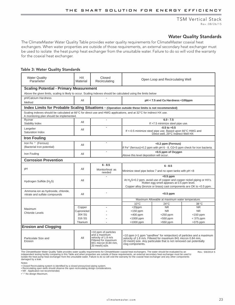
Table 3: Water Quality Standards
The ClimateMaster Water Quality Table provides water quality requirements for ClimateMaster coaxial heat exchangers. When water properties are outside of those requirements, an external secondary heat exchanger must be used to isolate the heat pump heat exchanger from the unsuitable water. Failure to do so will void the warranty for the coaxial heat exchanger.
Water Quality Standards
Water QualityParameter
HXMaterial
ClosedRecirculating Open Loop and Recirculating Well
Scaling Potential - Primary Measurement
pH/Calcium HardnessAll
-pH < 7.5 and Ca Hardness <100ppm
Method
Index Limits for Probable Scaling Situations - (Operation outside these limits is not recommended)
RyznarAll
- 6.0 - 7.5Stability Index If >7.5 minimize steel pipe use.
Langelier All- -0.5 to +0.5
Saturation Index If <-0.5 minimize steel pipe use. Based upon 66°C HWG andDirect well, 29°C Indirect Well HX
Iron FoulingIron Fe 2+ (Ferrous) All
- <0.2 ppm (Ferrous)(Bacterial Iron potential) If Fe2+ (ferrous)>0.2 ppm with pH 6 - 8, O2<5 ppm check for iron bacteria.
Iron Fouling All- <0.5 ppm of Oxygen
Above this level deposition will occur .
Corrosion Prevention
pH All6 - 8.5 6 - 8.5
Monitor/treat asneeded Minimize steel pipe below 7 and no open tanks with pH <8
Hydrogen Sulfide (H2S) All- <0.5 ppm
At H2S>0.2 ppm, avoid use of copper and copper nickel piping or HX's.Rotten egg smell appears at 0.5 ppm level.
Copper alloy (bronze or brass) cast components are OK to <0.5 ppm.Ammonia ion as hydroxide, chloride, nitrate and sulfate compounds All - <0.5 ppm
Maximum
Maximum Allowable at maximum water temperature.
Chloride Levels
10 C 24 C 38 CCopper
Cupronickel- <20ppm NR NR- <150 ppm NR NR
304 SS - <400 ppm <250 ppm <150 ppm316 SS - <1000 ppm <550 ppm < 375 ppm
Titanium - >1000 ppm >550 ppm >375 ppm
Erosion and Clogging
Particulate Size andErosion
All
<10 ppm of particlesand a maximumvelocity of 1.8 m/sFiltered for maximum841 micron [0.84 mm,20 mesh] size.
<10 ppm (<1 ppm "sandfree” for reinjection) of particles and a maximum velocity of 1.8 m/s. Filtered for maximum 841 micron 0.84 mm,20 mesh] size. Any particulate that is not removed can potentiallyclog components.
Notes:
Rev.: 5/6/2014 S
• NR - Application not recommended.• "-" No design Maximum.
• Closed Recirculating system is identified by a closed pressurized piping system.• Recirculating open wells should observe the open recirculating design considerations.
Above the given limits, scaling is likely to occur. Scaling indexes should be calculated using the limits below
Scaling indexes should be calculated at 66°C for direct use and HWG applications, and at 32°C for indirect HX use. A monitoring plan should be implemented.
The ClimateMaster Water Quality Table provides water quality requirements for ClimateMaster coaxial heat exchangers. The water should be evaluated by an independent testing facility comparing to this Table and when properties are outside of these requirements, an external secondary heat exchanger must be used to isolate the heat pump heat exchanger from the unsuitable water. Failure to do so will void the warranty for the coaxial heat exchanger and any other components damaged by a leak.
CLIMATEMASTER WATER-SOURCE HEAT PUMPS
TSM Vertical StackR e v. : 0 8 / 2 6 / 1 5
24 C l i m a t e M a s t e r Wa t e r - S o u r c e H e a t P u m p s
Electrical Wiring - Line Voltage
Electrical - Line VoltageAll fi eld installed wiring, including electrical ground, must comply with the National Electrical Code as well as all applicable local codes. Refer to the unit electrical data for fuse sizes. Consult wiring diagram for fi eld connections that must be made by the installing (or electrical) contractor.All fi nal electrical connections must be made with a length of fl exible conduit to minimize vibration and sound transmission to the building.
WARNING! To avoid possible injury or death due to electrical shock, open the power supply disconnect switch and secure it in an open position during installation.
CAUTION! Use only copper conductors for fi eld installed electrical wiring. Unit terminals are not designed to accept other types of conductors.
CAUTION!
General Line Voltage Wiring - Be sure the available power is the same voltage and phase shown on the unit serial plate. Line and low voltage wiring must be done in accordance with local codes or the National Electric Code, whichever is applicable.
Power Connection - Line voltage connection is made by connecting the incoming line voltage wires to the “L” side of the contactor.
208 Volt Operation - All commercial 208/230 Volt units are factory wired for 208 Volt operation. If supply voltage is 230V, then the transformer must be rewired to the 230V tap as illustrated on the wiring diagram by switching the red (208V) and the orange (230V) wires at the contactor terminal.
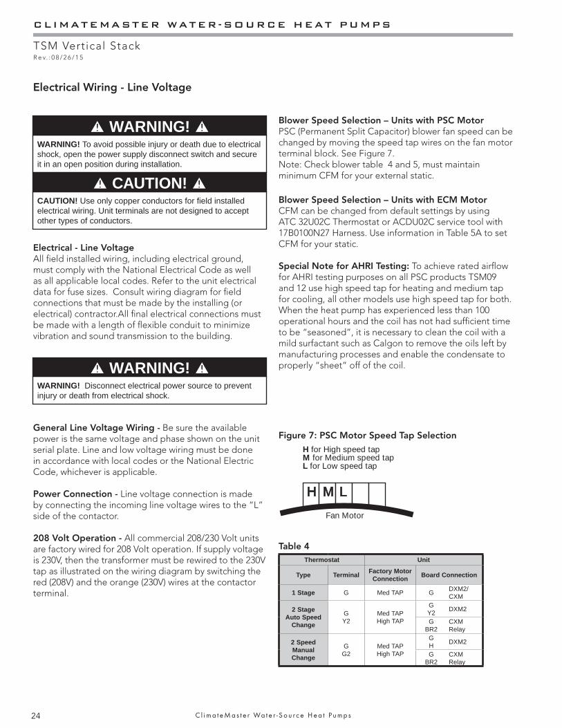
Blower Speed Selection – Units with PSC MotorPSC (Permanent Split Capacitor) blower fan speed can be changed by moving the speed tap wires on the fan motor terminal block. See Figure 7. Note: Check blower table 4 and 5, must maintain minimum CFM for your external static.
Blower Speed Selection – Units with ECM MotorCFM can be changed from default settings by using ATC 32U02C Thermostat or ACDU02C service tool with 17B0100N27 Harness. Use information in Table 5A to set CFM for your static.
Special Note for AHRI Testing: To achieve rated airfl ow for AHRI testing purposes on all PSC products TSM09 and 12 use high speed tap for heating and medium tap for cooling, all other models use high speed tap for both. When the heat pump has experienced less than 100 operational hours and the coil has not had suffi cient time to be “seasoned”, it is necessary to clean the coil with a mild surfactant such as Calgon to remove the oils left by manufacturing processes and enable the condensate to properly “sheet” off of the coil.
WARNING! Disconnect electrical power source to prevent injury or death from electrical shock.
WARNING!
H for High speed tapM for Medium speed tapL for Low speed tap
Fan Motor
Figure 7: PSC Motor Speed Tap Selection
Table 4Thermostat Unit
Type Terminal Factory Motor Connection Board Connection
1 Stage G Med TAP G DXM2/CXM
2 Stage Auto Speed
Change
GY2
Med TAPHigh TAP
GY2 DXM2
GBR2
CXM Relay
2 Speed Manual Change
GG2
Med TAPHigh TAP
GH DXM2
GBR2
CXM Relay
WARNING!
THE SMART SOLUTION FOR ENERGY EFFICIENCY
TSM Vertical StackR e v. : 0 8 / 2 6 / 1 5
25c l i m a t e m a s t e r . c o m
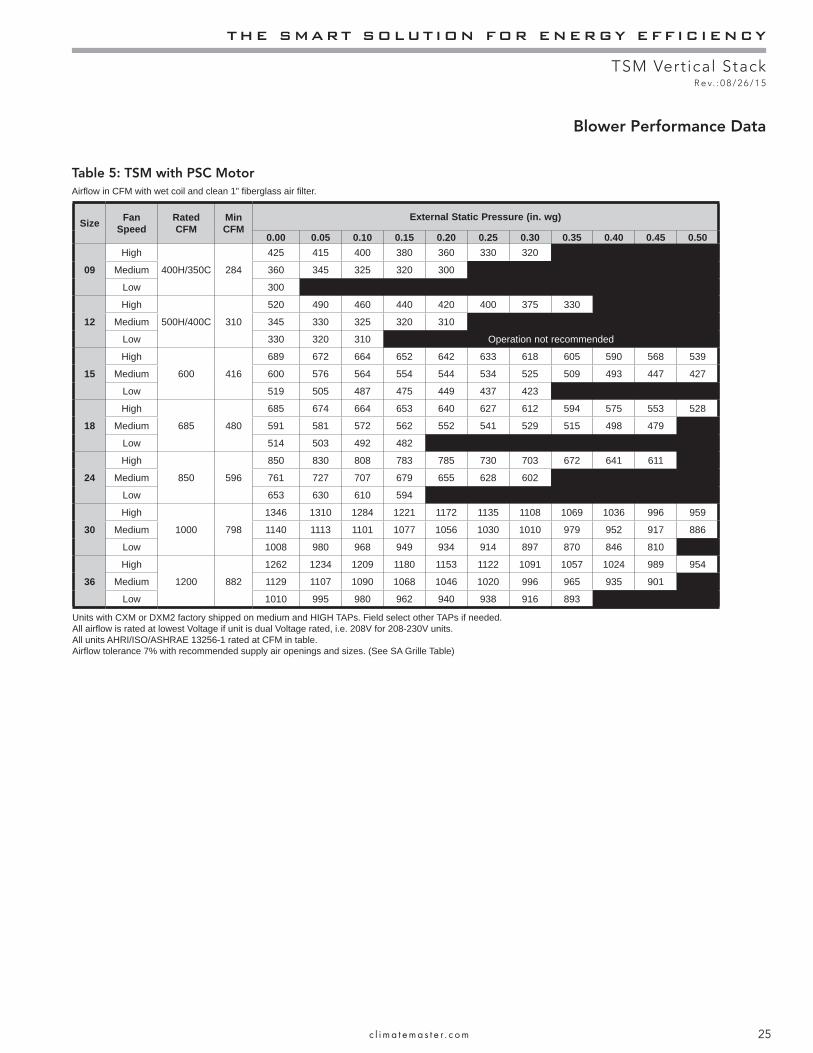
Blower Performance Data
Table 5: TSM with PSC MotorAirfl ow in CFM with wet coil and clean 1” fi berglass air fi lter.
Size Fan Speed
Rated CFM
Min CFM
External Static Pressure (in. wg)
0.00 0.05 0.10 0.15 0.20 0.25 0.30 0.35 0.40 0.45 0.50
09
High
400H/350C 284
425 415 400 380 360 330 320
Medium 360 345 325 320 300 * *
Low 300
12
High
500H/400C 310
520 490 460 440 420 400 375 330
Medium 345 330 325 320 310
Low 330 320 310 Operation not recommended
15
High
600 416
689 672 664 652 642 633 618 605 590 568 539
Medium 600 576 564 554 544 534 525 509 493 447 427
Low 519 505 487 475 449 437 423
18
High
685 480
685 674 664 653 640 627 612 594 575 553 528
Medium 591 581 572 562 552 541 529 515 498 479
Low 514 503 492 482
24
High
850 596
850 830 808 783 785 730 703 672 641 611
Medium 761 727 707 679 655 628 602
Low 653 630 610 594
30
High
1000 798
1346 1310 1284 1221 1172 1135 1108 1069 1036 996 959
Medium 1140 1113 1101 1077 1056 1030 1010 979 952 917 886
Low 1008 980 968 949 934 914 897 870 846 810
36
High
1200 882
1262 1234 1209 1180 1153 1122 1091 1057 1024 989 954
Medium 1129 1107 1090 1068 1046 1020 996 965 935 901
Low 1010 995 980 962 940 938 916 893
Units with CXM or DXM2 factory shipped on medium and HIGH TAPs. Field select other TAPs if needed.All airfl ow is rated at lowest Voltage if unit is dual Voltage rated, i.e. 208V for 208-230V units.All units AHRI/ISO/ASHRAE 13256-1 rated at CFM in table.Airfl ow tolerance 7% with recommended supply air openings and sizes. (See SA Grille Table)
CLIMATEMASTER WATER-SOURCE HEAT PUMPS
TSM Vertical StackR e v. : 0 8 / 2 6 / 1 5
26 C l i m a t e M a s t e r Wa t e r - S o u r c e H e a t P u m p s
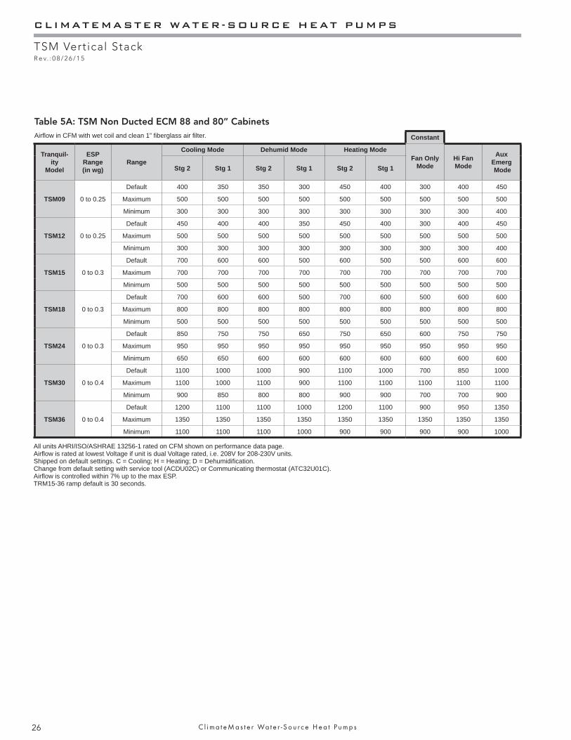
Table 5A: TSM Non Ducted ECM 88 and 80” CabinetsAirfl ow in CFM with wet coil and clean 1” fi berglass air fi lter.
All units AHRI/ISO/ASHRAE 13256-1 rated on CFM shown on performance data page.Airfl ow is rated at lowest Voltage if unit is dual Voltage rated, i.e. 208V for 208-230V units.Shipped on default settings. C = Cooling; H = Heating; D = Dehumidifi cation.Change from default setting with service tool (ACDU02C) or Communicating thermostat (ATC32U01C).Airfl ow is controlled within 7% up to the max ESP.TRM15-36 ramp default is 30 seconds.
Constant
Tranquil-ity
Model
ESP Range(in wg)
Range
Cooling Mode Dehumid Mode Heating Mode Fan Only
ModeHi Fan Mode
Aux Emerg ModeStg 2 Stg 1 Stg 2 Stg 1 Stg 2 Stg 1
TSM09 0 to 0.25
Default 400 350 350 300 450 400 300 400 450
Maximum 500 500 500 500 500 500 500 500 500
Minimum 300 300 300 300 300 300 300 300 400
TSM12 0 to 0.25
Default 450 400 400 350 450 400 300 400 450
Maximum 500 500 500 500 500 500 500 500 500
Minimum 300 300 300 300 300 300 300 300 400
TSM15 0 to 0.3
Default 700 600 600 500 600 500 500 600 600
Maximum 700 700 700 700 700 700 700 700 700
Minimum 500 500 500 500 500 500 500 500 500
TSM18 0 to 0.3
Default 700 600 600 500 700 600 500 600 600
Maximum 800 800 800 800 800 800 800 800 800
Minimum 500 500 500 500 500 500 500 500 500
TSM24 0 to 0.3
Default 850 750 750 650 750 650 600 750 750
Maximum 950 950 950 950 950 950 950 950 950
Minimum 650 650 600 600 600 600 600 600 600
TSM30 0 to 0.4
Default 1100 1000 1000 900 1100 1000 700 850 1000
Maximum 1100 1000 1100 900 1100 1100 1100 1100 1100
Minimum 900 850 800 800 900 900 700 700 900
TSM36 0 to 0.4
Default 1200 1100 1100 1000 1200 1100 900 950 1350
Maximum 1350 1350 1350 1350 1350 1350 1350 1350 1350
Minimum 1100 1100 1100 1000 900 900 900 900 1000
THE SMART SOLUTION FOR ENERGY EFFICIENCY
TSM Vertical StackR e v. : 0 8 / 2 6 / 1 5
27c l i m a t e m a s t e r . c o m
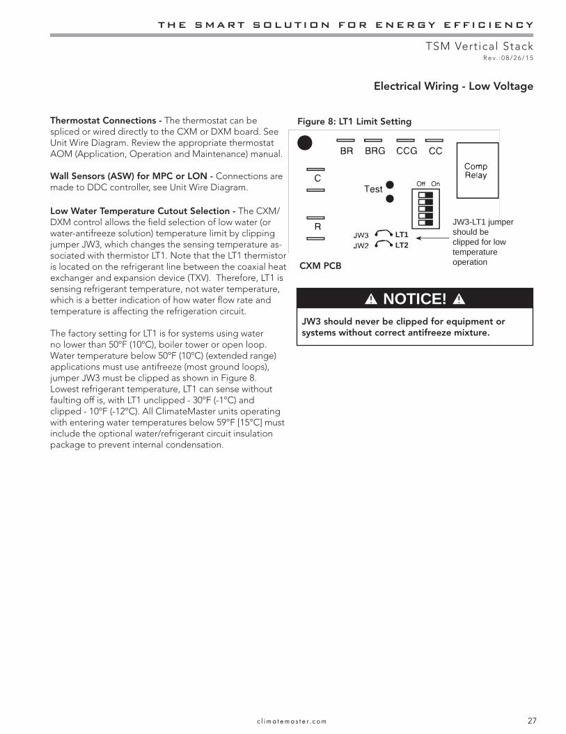
JW3 should never be clipped for equipment or systems without correct antifreeze mixture.
NOTICE!
Electrical Wiring - Low Voltage
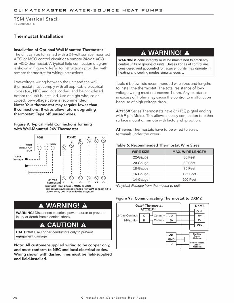
Thermostat Connections - The thermostat can be spliced or wired directly to the CXM or DXM board. See Unit Wire Diagram. Review the appropriate thermostat AOM (Application, Operation and Maintenance) manual.
Wall Sensors (ASW) for MPC or LON - Connections are made to DDC controller, see Unit Wire Diagram.
Low Water Temperature Cutout Selection - The CXM/DXM control allows the fi eld selection of low water (or water-antifreeze solution) temperature limit by clipping jumper JW3, which changes the sensing temperature as-sociated with thermistor LT1. Note that the LT1 thermistor is located on the refrigerant line between the coaxial heat exchanger and expansion device (TXV). Therefore, LT1 is sensing refrigerant temperature, not water temperature, which is a better indication of how water fl ow rate and temperature is affecting the refrigeration circuit.
The factory setting for LT1 is for systems using water no lower than 50ºF (10ºC), boiler tower or open loop. Water temperature below 50ºF (10ºC) (extended range) applications must use antifreeze (most ground loops), jumper JW3 must be clipped as shown in Figure 8. Lowest refrigerant temperature, LT1 can sense without faulting off is, with LT1 unclipped - 30ºF (-1ºC) and clipped - 10ºF (-12ºC). All ClimateMaster units operating with entering water temperatures below 59°F [15°C] must include the optional water/refrigerant circuit insulation package to prevent internal condensation.
Figure 8: LT1 Limit Setting
CXM PCB
LT1LT2
JW3-LT1 jumper should be clipped for low temperature operation
CLIMATEMASTER WATER-SOURCE HEAT PUMPS
TSM Vertical StackR e v. : 0 8 / 2 6 / 1 5
28 C l i m a t e M a s t e r Wa t e r - S o u r c e H e a t P u m p s
Table 6 below lists recommended wire sizes and lengths to install the thermostat. The total resistance of low-voltage wiring must not exceed 1 ohm. Any resistance in excess of 1 ohm may cause the control to malfunction because of high voltage drop.
A91558 Series Thermostats have 6” (152) pigtail ending with 9-pin Molex. This allows an easy connection to either surface mount or remote with factory whip option.
AT Series Thermostats have to be wired to screw terminals under the cover.
Installation of Optional Wall-Mounted Thermostat - The unit can be furnished with a 24-volt surface mounted ACO or MCO control circuit or a remote 24-volt ACO or MCO thermostat. A typical fi eld connection diagram is shown in Figure 9. Refer to instructions provided with remote thermostat for wiring instructions.
Low-voltage wiring between the unit and the wall thermostat must comply with all applicable electrical codes (i.e., NEC and local codes), and be completed before the unit is installed. Use of eight wire, color-coded, low-voltage cable is recommended.Note: Your thermostat may require fewer than 8 connections, 8 wires allow future upgrading thermostat. Tape off unused wires.
Note: All customer-supplied wiring to be copper only, and must conform to NEC and local electrical codes. Wiring shown with dashed lines must be fi eld-supplied and fi eld-installed.
UNITJUNCTION
BOX
L1 L2 GNDR
C
C
GY H
Y2
O
R G Y O24 Vac
Thermostat
PDB DXM2
Line Voltage
Digital 2 Heat, 2 Cool, MCO, or ACOWill provide auto speed change (for CXM connect Y2 to blower relay coil - see unit wire diagram).
Table 6: Recommended Thermostat Wire Sizes
WARNING! Disconnect electrical power source to prevent injury or death from electrical shock.
CAUTION! Use copper conductors only to prevent equipment damage
Figure 9: Typical Field Connections for units with Wall-Mounted 24V Thermostat
WARNING! WARNING! Zone integrity must be maintained to effi ciently control units or groups of units. Unless zones of control are considered and accounted for, adjacent units may operate in heating and cooling modes simultaneously.
WIRE SIZE MAX. WIRE LENGTH22-Gauge 30 Feet20-Gauge 50 Feet18-Gauge 75 Feet16-Gauge 125 Feet14-Gauge 200 Feet
*Physical distance from thermostat to unit
Thermostat Installation
WARNING!
CAUTION!
Figure 9a: Communicating Thermostat to DXM2
iGate® ThermostatATC32U**
24Vac Hot
DXM2
24V
Comm + A+A+
Comm - B-B-
OD
ID
GND
OutdoorSensor
(Optiona)
Remote IndoorSensor
(Optiona)
24Vac Common
Gnd
R
C
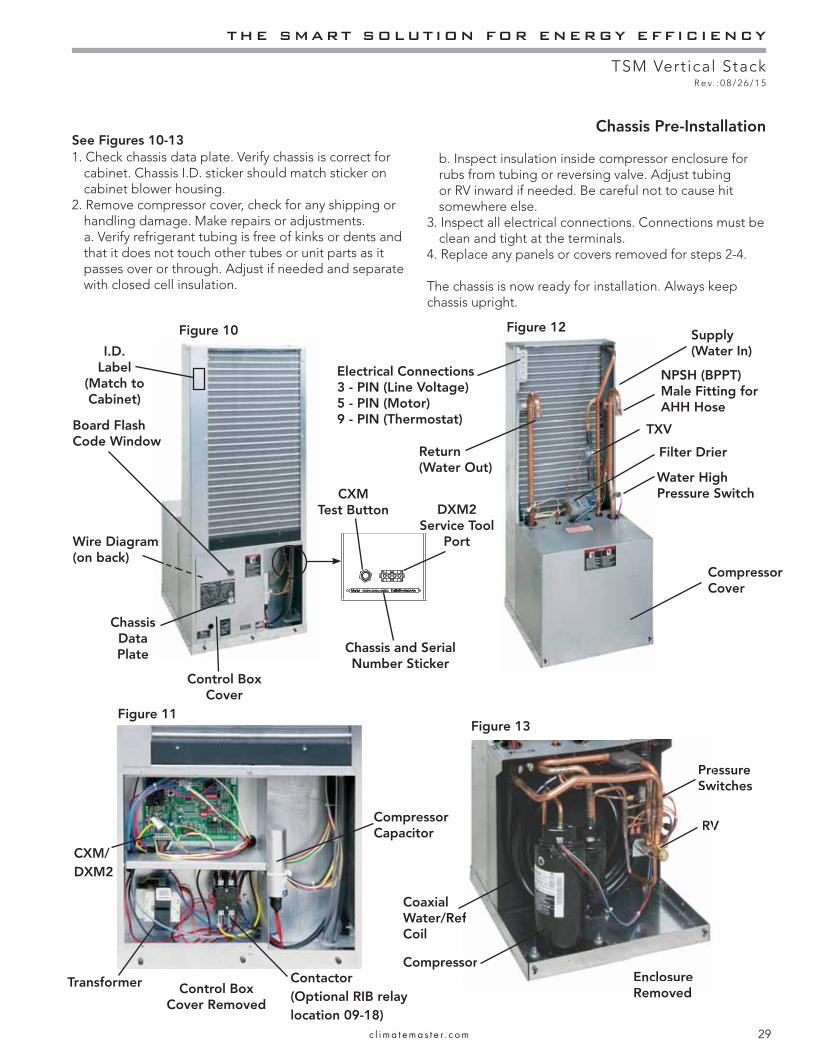
THE SMART SOLUTION FOR ENERGY EFFICIENCY
TSM Vertical StackR e v. : 0 8 / 2 6 / 1 5
29c l i m a t e m a s t e r . c o m
Chassis Pre-Installation
1. Check chassis data plate. Verify chassis is correct for cabinet. Chassis I.D. sticker should match sticker on cabinet blower housing.
2. Remove compressor cover, check for any shipping or handling damage. Make repairs or adjustments.
a. Verify refrigerant tubing is free of kinks or dents and that it does not touch other tubes or unit parts as it passes over or through. Adjust if needed and separate with closed cell insulation.
b. Inspect insulation inside compressor enclosure for rubs from tubing or reversing valve. Adjust tubing or RV inward if needed. Be careful not to cause hit somewhere else.
3. Inspect all electrical connections. Connections must be clean and tight at the terminals.
4. Replace any panels or covers removed for steps 2-4.
The chassis is now ready for installation. Always keep chassis upright.
Figure 12Figure 10
Figure 11Figure 13
CXM/DXM2
Transformer
Water High Pressure Switch
RV
TXV
NPSH (BPPT) Male Fitting for AHH Hose
Filter Drier
Chassis Data Plate
Compressor Cover
Compressor
Coaxial Water/Ref Coil
Compressor Capacitor
Pressure Switches
Enclosure RemovedControl Box
Cover Removed
See Figures 10-13
Electrical Connections3 - PIN (Line Voltage)5 - PIN (Motor)9 - PIN (Thermostat)
Return(Water Out)
Supply(Water In)
Contactor(Optional RIB relay location 09-18)
Wire Diagram (on back)
CXM Test Button DXM2
Service Tool Port
Board Flash Code Window
I.D.Label
(Match to Cabinet)
Control Box Cover
Chassis and Serial Number Sticker
RV
sor
f
PreSw
EnclosureR d
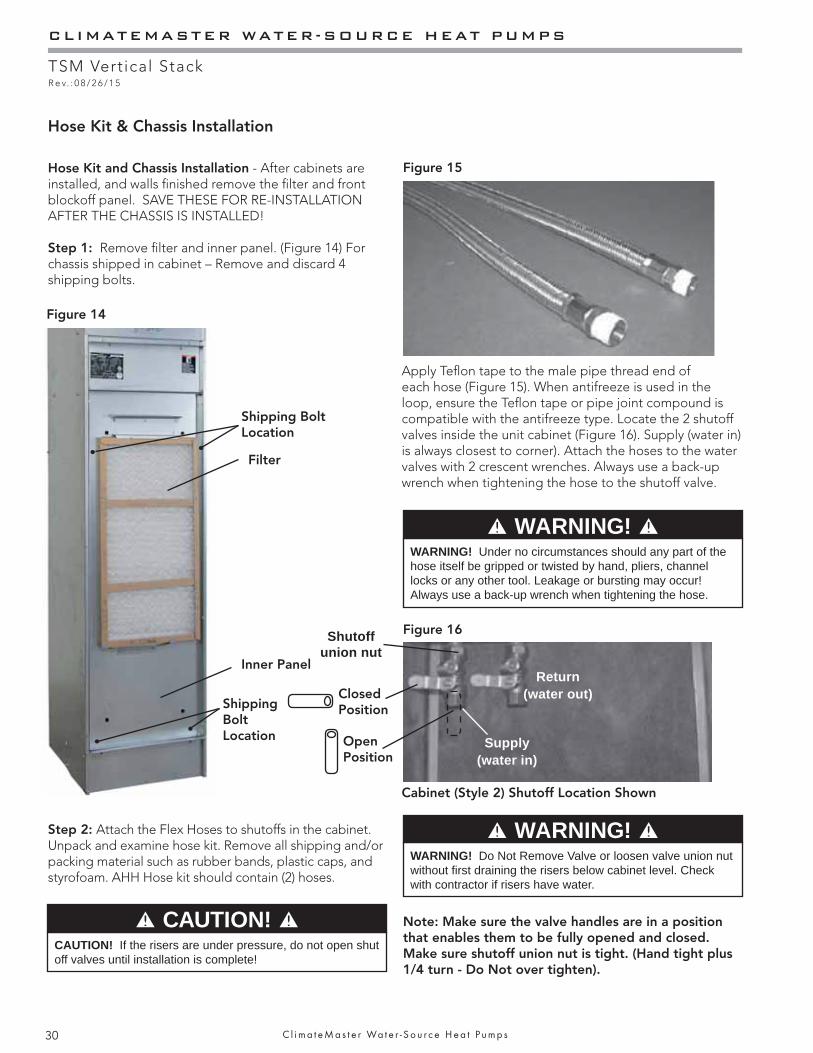
CLIMATEMASTER WATER-SOURCE HEAT PUMPS
TSM Vertical StackR e v. : 0 8 / 2 6 / 1 5
30 C l i m a t e M a s t e r Wa t e r - S o u r c e H e a t P u m p s
Hose Kit & Chassis Installation
Hose Kit and Chassis Installation - After cabinets are installed, and walls fi nished remove the fi lter and front blockoff panel. SAVE THESE FOR RE-INSTALLATION AFTER THE CHASSIS IS INSTALLED!
Step 1: Remove fi lter and inner panel. (Figure 14) For chassis shipped in cabinet – Remove and discard 4 shipping bolts.
Figure 14
Step 2: Attach the Flex Hoses to shutoffs in the cabinet. Unpack and examine hose kit. Remove all shipping and/or packing material such as rubber bands, plastic caps, and styrofoam. AHH Hose kit should contain (2) hoses.
Figure 15
Apply Tefl on tape to the male pipe thread end of each hose (Figure 15). When antifreeze is used in the loop, ensure the Tefl on tape or pipe joint compound is compatible with the antifreeze type. Locate the 2 shutoff valves inside the unit cabinet (Figure 16). Supply (water in) is always closest to corner). Attach the hoses to the water valves with 2 crescent wrenches. Always use a back-up wrench when tightening the hose to the shutoff valve.
Figure 16
WARNING! WARNING! Under no circumstances should any part of the hose itself be gripped or twisted by hand, pliers, channel locks or any other tool. Leakage or bursting may occur! Always use a back-up wrench when tightening the hose.
CAUTION! CAUTION! If the risers are under pressure, do not open shut off valves until installation is complete!
Note: Make sure the valve handles are in a position that enables them to be fully opened and closed. Make sure shutoff union nut is tight. (Hand tight plus 1/4 turn - Do Not over tighten).
Cabinet (Style 2) Shutoff Location Shown
WARNING! WARNING! Do Not Remove Valve or loosen valve union nut without fi rst draining the risers below cabinet level. Check with contractor if risers have water.
Shutoff union nut
Supply (water in)
Return (water out)
Filter
Shipping Bolt Location
Shipping Bolt Location
Inner Panel
Closed Position
Open Position
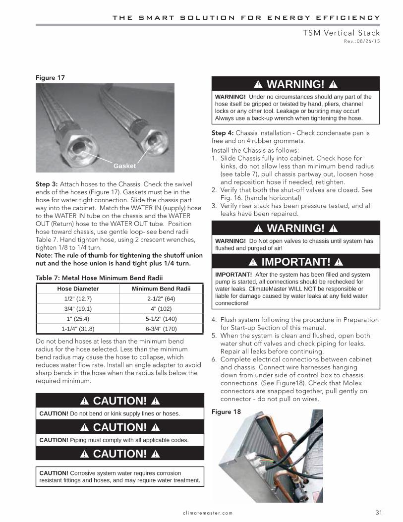
THE SMART SOLUTION FOR ENERGY EFFICIENCY
TSM Vertical StackR e v. : 0 8 / 2 6 / 1 5
31c l i m a t e m a s t e r . c o m
Figure 17
Gasket
Step 3: Attach hoses to the Chassis. Check the swivel ends of the hoses (Figure 17). Gaskets must be in the hose for water tight connection. Slide the chassis part way into the cabinet. Match the WATER IN (supply) hose to the WATER IN tube on the chassis and the WATER OUT (Return) hose to the WATER OUT tube. Position hose toward chassis, use gentle loop- see bend radii Table 7. Hand tighten hose, using 2 crescent wrenches, tighten 1/8 to 1/4 turn.Note: The rule of thumb for tightening the shutoff union nut and the hose union is hand tight plus 1/4 turn.
WARNING! WARNING! Under no circumstances should any part of the hose itself be gripped or twisted by hand, pliers, channel locks or any other tool. Leakage or bursting may occur! Always use a back-up wrench when tightening the hose.
Step 4: Chassis Installation - Check condensate pan is free and on 4 rubber grommets.Install the Chassis as follows:1. Slide Chassis fully into cabinet. Check hose for
kinks, do not allow less than minimum bend radius (see table 7), pull chassis partway out, loosen hose and reposition hose if needed, retighten.
2. Verify that both the shut-off valves are closed. See Fig. 16. (handle horizontal)
3. Verify riser stack has been pressure tested, and all leaks have been repaired.
4. Flush system following the procedure in Preparation for Start-up Section of this manual.
5. When the system is clean and fl ushed, open both water shut off valves and check piping for leaks. Repair all leaks before continuing.
6. Complete electrical connections between cabinet and chassis. Connect wire harnesses hanging down from under side of control box to chassis connections. (See Figure18). Check that Molex connectors are snapped together, pull gently on connector - do not pull on wires.
Figure 18
WARNING! WARNING! Do Not open valves to chassis until system has fl ushed and purged of air!
IMPORTANT! IMPORTANT! After the system has been fi lled and system pump is started, all connections should be rechecked for water leaks. ClimateMaster WILL NOT be responsible or liable for damage caused by water leaks at any fi eld water connections!
CAUTION! Corrosive system water requires corrosion resistant fi ttings and hoses, and may require water treatment.
Do not bend hoses at less than the minimum bend radius for the hose selected. Less than the minimum bend radius may cause the hose to collapse, which reduces water fl ow rate. Install an angle adapter to avoid sharp bends in the hose when the radius falls below the required minimum.
Table 7: Metal Hose Minimum Bend Radii
Hose Diameter Minimum Bend Radii1/2" (12.7) 2-1/2" (64)
3/4" (19.1) 4" (102)
1" (25.4) 5-1/2" (140)
1-1/4" (31.8) 6-3/4" (170)
CAUTION!
CAUTION! CAUTION! Piping must comply with all applicable codes.
CAUTION! Do not bend or kink supply lines or hoses.
CAUTION!
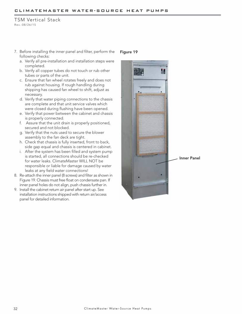
CLIMATEMASTER WATER-SOURCE HEAT PUMPS
TSM Vertical StackR e v. : 0 8 / 2 6 / 1 5
32 C l i m a t e M a s t e r Wa t e r - S o u r c e H e a t P u m p s
Figure 19
Inner Panel
7. Before installing the inner panel and fi lter, perform the following checks: a. Verify all pre-installation and installation steps were
completed. b. Verify all copper tubes do not touch or rub other
tubes or parts of the unit. c. Ensure that fan wheel rotates freely and does not
rub against housing. If rough handling during shipping has caused fan wheel to shift, adjust as necessary.
d. Verify that water piping connections to the chassis are complete and that unit service valves which were closed during fl ushing have been opened.
e. Verify that power between the cabinet and chassis is properly connected.
f. Assure that the unit drain is properly positioned, secured and not blocked.
g. Verify that the nuts used to secure the blower assembly to the fan deck are tight.
h. Check that chassis is fully inserted, front to back, side gap equal and chassis is centered in cabinet.
i. After the system has been fi lled and system pump is started, all connections should be re-checked for water leaks. ClimateMaster WILL NOT be responsible or liable for damage caused by water leaks at any fi eld water connections!
8. Re-attach the inner panel (8 screws) and fi lter as shown in Figure 19. Chassis must free fl oat on condensate pan. If inner panel holes do not align, push chassis further in.
9. Install the cabinet return air panel after start up. See installation instructions shipped with return air/access panel for detailed information.

THE SMART SOLUTION FOR ENERGY EFFICIENCY
TSM Vertical StackR e v. : 0 8 / 2 6 / 1 5
33c l i m a t e m a s t e r . c o m
Start-Up Preparation
System Cleaning and Flushing - Cleaning and fl ushing the unit is the single most important step to ensure proper start-up and continued effi cient operation of the system. Follow the instructions below to properly clean and fl ush the system: Do not fl ush through TSM chassis. Coax can get plugged and water fl ow will be reduced, causing poor performance and may cause LT1 sensor to trip.
1. Verify that electrical power to the unit is disconnected.2. Verify that supply and return riser service valves are
closed at each unit.3. Fill the system with water. Bleed all air from the system
but do not allow the system to over fl ow. Check the system for leaks and make any required repairs.
4. Adjust the water and air level in the expansion tank.5. With strainers in place, (ClimateMaster recommends a
strainer with a #20 stainless steel wire mesh) start the pumps. Systematically check that all of the air is bled from the system.
6. Verify that make-up water is available and adjusted to properly replace any space remaining when all air is evacuated. Check the system for leaks and make any additional repairs required.
7. Set the boiler to raise the loop temperature to approximately 85°F [29.4°C]. Open the drain at the lowest point in the system. Verify that make-up water replacement rate equals rate of bleed. Continue to bleed the system until the water appears clean or for at least three hours whichever is longer.
8. Completely drain the system.
Flush risers as follows: (Refer to Figure 20).1. Remove cabinet fi lter and front inner panel. Save
these for reinstallation after the chassis is installed.2. Close shut-off valves at each cabinet on the riser
except the shut-off valve on the top fl oor. 3. At the top fl oor, install the hose kit and connect the
ends of the hoses with the factory riser fl ush adapter from AFL5751.
4. Flush solution through supply riser. Note: The solution passes through the top fl oor connection down the return riser.
5. When the building has more than 10 fl oors, connect the supply and return runouts on the top two fl oors to divide the water fl ow and reduce pressure drop at the pump.
6. Repeat fl ushing procedure for each set of risers in the building.
7. Refi ll the system and add in a proportion of trisodium phosphate approximately one pound per 150 gallons [0.4kg per 500 liters] of water. Reset the boiler to raise the loop temperature to about 100°F [37.8°C].
8. Circulate the solution for between 8 to 24 hours. At the end of this period, shut off the circulating pump and drain the solution. Repeat system cleaning if desired.
9. Open the supply and return riser service valves at each unit. Refi ll the system and bleed off all air.
10. Units with internal pumps, to prevent cavitation and pump failure, air must be bleed from both sides of pump. First close off supply and open return shutoff. Open air bleed downstream of pump, bleed air, next close return and open supply shutoff, bleed air. Close air bleed.
11. Test the system pH with litmus paper. The system water should have a pH of 6 to 8.5. Add chemicals as appropriate to maintain pH levels.
12. When the system is successfully cleaned, fl ushed, refi lled, and bled, check the main system panels, safety cutouts, and alarms. Set controls to properly maintain loop temperature.
To Waste
Figure 20: Typical piping arrangement for fl ushing risers.
WARNING! WARNING! To prevent injury or death due to electrical shock or contact with moving part, open unit disconnect before servicing unit.
CAUTION! CAUTION! Do Not use "Stop-Leak" or any similar chemical agent in this system. Addition of these chemicals to the loop water can foul the system and can inhibit unit operation.
CAUTION! CAUTION! To avoid possible damage to piping systems constructed of plastic piping, DO NOT allow loop temperature to exceed 110°F [43.3°C].
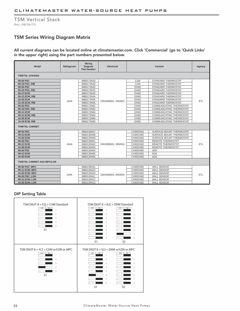
CLIMATEMASTER WATER-SOURCE HEAT PUMPS
TSM Vertical StackR e v. : 0 8 / 2 6 / 1 5
34 C l i m a t e M a s t e r Wa t e r - S o u r c e H e a t P u m p s
TSM Series Wiring Diagram Matrix
DIP Setting Table
All current diagrams can be located online at climatemaster.com. Click ‘Commercial’ (go to ‘Quick Links’ in the upper right) using the part numbers presented below.
Model RefrigerantWiring
Diagram Part Number
Electrical Control Agency
TSM/TSL CHASSIS
09-36 PSC
410A
96B0173N33
230/208/60/1; 265/60/1
CXM STANDARD THERMOSTAT
ETL
09-18 PSC; RIB 96B0173N33 CXM STANDARD THERMOSTAT09-36 PSC 96B0173N32 DXM2 STANDARD THERMOSTAT09-18 PSC; RIB 96B0173N32 DXM2 STANDARD THERMOSTAT09-12 ECM 96B0173N34 DXM2 STANDARD THERMOSTAT09-12 ECM; RIB 96B0173N34 DXM2 STANDARD THERMOSTAT15-36 ECM 96B0173N35 DXM2 STANDARD THERMOSTAT15-18 ECM; RIB 96B0173N35 DXM2 STANDARD THERMOSTAT09-36 PSC 96B0173N62 DXM2 COMMUNICATING THERMOSTAT09-18 PSC; RIB 96B0173N62 DXM2 COMMUNICATING THERMOSTAT09-12 ECM 96B0173N64 DXM2 COMMUNICATING THERMOSTAT09-12 ECM; RIB 96B0173N64 DXM2 COMMUNICATING THERMOSTAT15-36 ECM 96B0173N65 DXM2 COMMUNICATING THERMOSTAT15-18 ECM; RIB 96B0173N65 DXM2 COMMUNICATING THERMOSTAT
TSM/TSL CABINET
09-36 PSC
410A
96B0135N07
230/208/60/1; 265/60/1
CXM/DXM2 SURFACE MOUNT THERMOSTAT
ETL
09-12 ECM 96B0135N08 CXM/DXM2 SURFACE MOUNT THERMOSTAT15-36 ECM 96B0135N09 CXM/DXM2 SURFACE MOUNT THERMOSTAT09-36 PSC 96B0135N01 CXM/DXM2 REMOTE THERMOSTST09-12 ECM 96B0135N02 CXM/DXM2 REMOTE THERMOSTST15-36 ECM 96B0135N03 CXM/DXM2 REMOTE THERMOSTST09-36 PSC 96B0135N04 CXM/DXM2 ADA09-12 ECM 96B0135N05 CXM/DXM2 ADA15-36 ECM 96B0135N06 CXM/DXM2 ADA
TSM/TSL CABINET AUX MPC/LON
09-36 PSC; MPC
410A
96B0135N21
230/208/60/1; 265/60/1
CXM/DXM2 WALL SENSOR
ETL
09-12 ECM; MPC 96B0135N22 CXM/DXM2 WALL SENSOR15-36 ECM; MPC 96B0135N23 CXM/DXM2 WALL SENSOR09-36 PSC; LON 96B0135N11 CXM/DXM2 WALL SENSOR09-12 ECM; LON 96B0135N12 CXM/DXM2 WALL SENSOR15-36 ECM; LON 96B0135N13 CXM/DXM2 WALL SENSOR
OFF ON OFF ON OFF ON1 1 1
2 2 2
3 3 3
4 4 4
5 5 5
6 6
7 7
8 8
OFF ON OFF ON OFF ON1 1
2 2 2
3 3 3
4 4 4
5 5 5
6 6
7 7
8 8
TSM DIGIT 8 = F,Q + CXM Standard
TSM DIGIT 8 = H,T + CXM w/LON or MPC TSM DIGIT 8 = V,U + DXM w/LON or MPC
TSM DIGIT 8 = K,G + DXM Standard
S1
S1
S1
S1
S2
S2
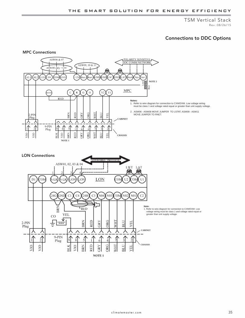
THE SMART SOLUTION FOR ENERGY EFFICIENCY
TSM Vertical StackR e v. : 0 8 / 2 6 / 1 5
35c l i m a t e m a s t e r . c o m
Notes:1. Refer to wire diagram for connection to CXM/DXM. Low voltage wiring must be class 1 and voltage rated equal or greater than unit supply voltage.
2. ASW06 - ASW08 MOVE JUMPER TO LSTAT, ASW09 - ASW11 MOVE JUMPER TO RNET.
CABINET
CHASSIS
NOTE 1
NOTE 2
HOT/R
MPC Connections
LON Connections
NOTE 1
Note:1. Refer to wire diagram for connection to CXM/DXM. Low voltage wiring must be class 1 and voltage rated equal or greater than unit supply voltage.
CABINET
CHASSIS
Connections to DDC Options
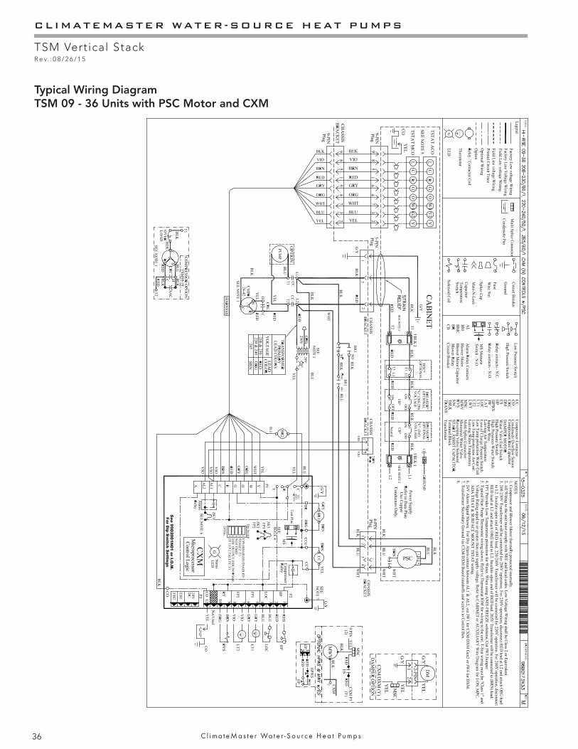
CLIMATEMASTER WATER-SOURCE HEAT PUMPS
TSM Vertical StackR e v. : 0 8 / 2 6 / 1 5
36 C l i m a t e M a s t e r Wa t e r - S o u r c e H e a t P u m p s
Typical Wiring DiagramTSM 09 - 36 Units with PSC Motor and CXM
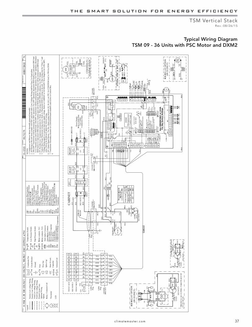
THE SMART SOLUTION FOR ENERGY EFFICIENCY
TSM Vertical StackR e v. : 0 8 / 2 6 / 1 5
37c l i m a t e m a s t e r . c o m
Typical Wiring DiagramTSM 09 - 36 Units with PSC Motor and DXM2
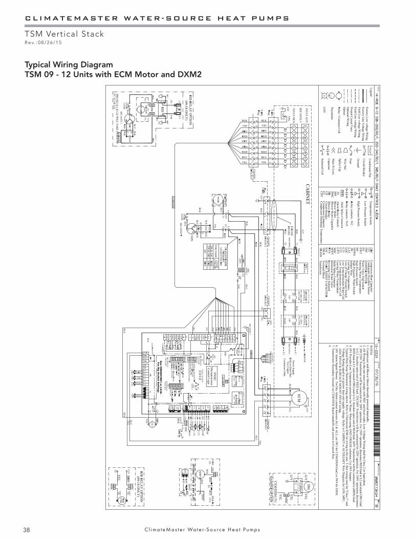
CLIMATEMASTER WATER-SOURCE HEAT PUMPS
TSM Vertical StackR e v. : 0 8 / 2 6 / 1 5
38 C l i m a t e M a s t e r Wa t e r - S o u r c e H e a t P u m p s
Typical Wiring DiagramTSM 09 - 12 Units with ECM Motor and DXM2
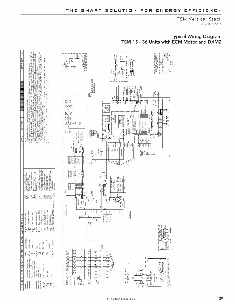
THE SMART SOLUTION FOR ENERGY EFFICIENCY
TSM Vertical StackR e v. : 0 8 / 2 6 / 1 5
39c l i m a t e m a s t e r . c o m
Typical Wiring DiagramTSM 15 - 36 Units with ECM Motor and DXM2
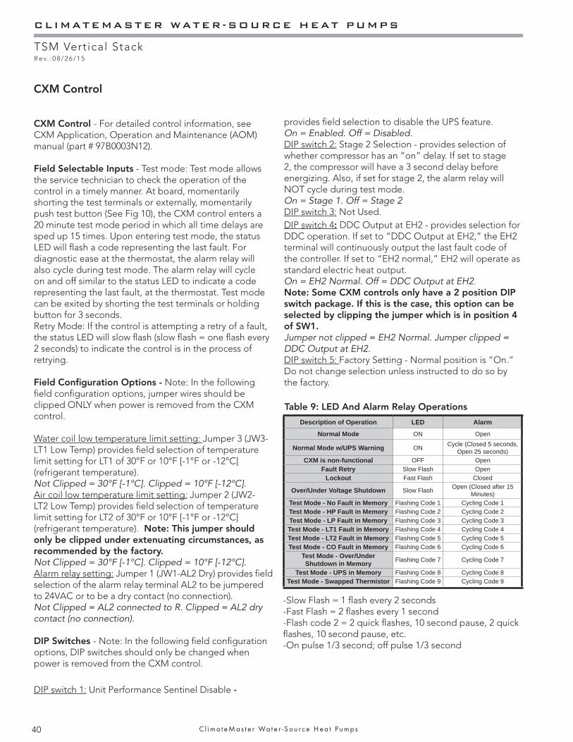
CLIMATEMASTER WATER-SOURCE HEAT PUMPS
TSM Vertical StackR e v. : 0 8 / 2 6 / 1 5
40 C l i m a t e M a s t e r Wa t e r - S o u r c e H e a t P u m p s
Table 9: LED And Alarm Relay Operations
CXM Control
CXM Control - For detailed control information, see CXM Application, Operation and Maintenance (AOM) manual (part # 97B0003N12).
Field Selectable Inputs - Test mode: Test mode allows the service technician to check the operation of the control in a timely manner. At board, momentarily shorting the test terminals or externally, momentarily push test button (See Fig 10), the CXM control enters a 20 minute test mode period in which all time delays are sped up 15 times. Upon entering test mode, the status LED will fl ash a code representing the last fault. For diagnostic ease at the thermostat, the alarm relay will also cycle during test mode. The alarm relay will cycle on and off similar to the status LED to indicate a code representing the last fault, at the thermostat. Test mode can be exited by shorting the test terminals or holding button for 3 seconds.Retry Mode: If the control is attempting a retry of a fault, the status LED will slow fl ash (slow fl ash = one fl ash every 2 seconds) to indicate the control is in the process of retrying.
Field Confi guration Options - Note: In the following fi eld confi guration options, jumper wires should be clipped ONLY when power is removed from the CXM control.
Water coil low temperature limit setting: Jumper 3 (JW3-LT1 Low Temp) provides fi eld selection of temperature limit setting for LT1 of 30°F or 10°F [-1°F or -12°C] (refrigerant temperature).Not Clipped = 30°F [-1°C]. Clipped = 10°F [-12°C].Air coil low temperature limit setting: Jumper 2 (JW2-LT2 Low Temp) provides fi eld selection of temperature limit setting for LT2 of 30°F or 10°F [-1°F or -12°C] (refrigerant temperature). Note: This jumper should only be clipped under extenuating circumstances, as recommended by the factory.Not Clipped = 30°F [-1°C]. Clipped = 10°F [-12°C].Alarm relay setting: Jumper 1 (JW1-AL2 Dry) provides fi eld selection of the alarm relay terminal AL2 to be jumpered to 24VAC or to be a dry contact (no connection).Not Clipped = AL2 connected to R. Clipped = AL2 dry contact (no connection).
DIP Switches - Note: In the following fi eld confi guration options, DIP switches should only be changed when power is removed from the CXM control.
DIP switch 1: Unit Performance Sentinel Disable -
provides fi eld selection to disable the UPS feature.On = Enabled. Off = Disabled.DIP switch 2: Stage 2 Selection - provides selection of whether compressor has an “on” delay. If set to stage 2, the compressor will have a 3 second delay before energizing. Also, if set for stage 2, the alarm relay will NOT cycle during test mode.On = Stage 1. Off = Stage 2DIP switch 3: Not Used.DIP switch 4: DDC Output at EH2 - provides selection for DDC operation. If set to “DDC Output at EH2,” the EH2 terminal will continuously output the last fault code of the controller. If set to “EH2 normal,” EH2 will operate as standard electric heat output.On = EH2 Normal. Off = DDC Output at EH2.Note: Some CXM controls only have a 2 position DIP switch package. If this is the case, this option can be selected by clipping the jumper which is in position 4 of SW1.Jumper not clipped = EH2 Normal. Jumper clipped = DDC Output at EH2.DIP switch 5: Factory Setting - Normal position is “On.” Do not change selection unless instructed to do so by the factory.
Description of Operation LED Alarm
Normal Mode ON Open
Normal Mode w/UPS Warning ON Cycle (Closed 5 seconds, Open 25 seconds)
CXM is non-functional OFF OpenFault Retry Slow Flash Open
Lockout Fast Flash Closed
Over/Under Voltage Shutdown Slow Flash Open (Closed after 15 Minutes)
Test Mode - No Fault in Memory Flashing Code 1 Cycling Code 1Test Mode - HP Fault in Memory Flashing Code 2 Cycling Code 2Test Mode - LP Fault in Memory Flashing Code 3 Cycling Code 3Test Mode - LT1 Fault in Memory Flashing Code 4 Cycling Code 4Test Mode - LT2 Fault in Memory Flashing Code 5 Cycling Code 5Test Mode - CO Fault in Memory Flashing Code 6 Cycling Code 6
Test Mode - Over/Under Shutdown in Memory Flashing Code 7 Cycling Code 7
Test Mode - UPS in Memory Flashing Code 8 Cycling Code 8Test Mode - Swapped Thermistor Flashing Code 9 Cycling Code 9
-Slow Flash = 1 fl ash every 2 seconds-Fast Flash = 2 fl ashes every 1 second-Flash code 2 = 2 quick fl ashes, 10 second pause, 2 quick fl ashes, 10 second pause, etc.-On pulse 1/3 second; off pulse 1/3 second
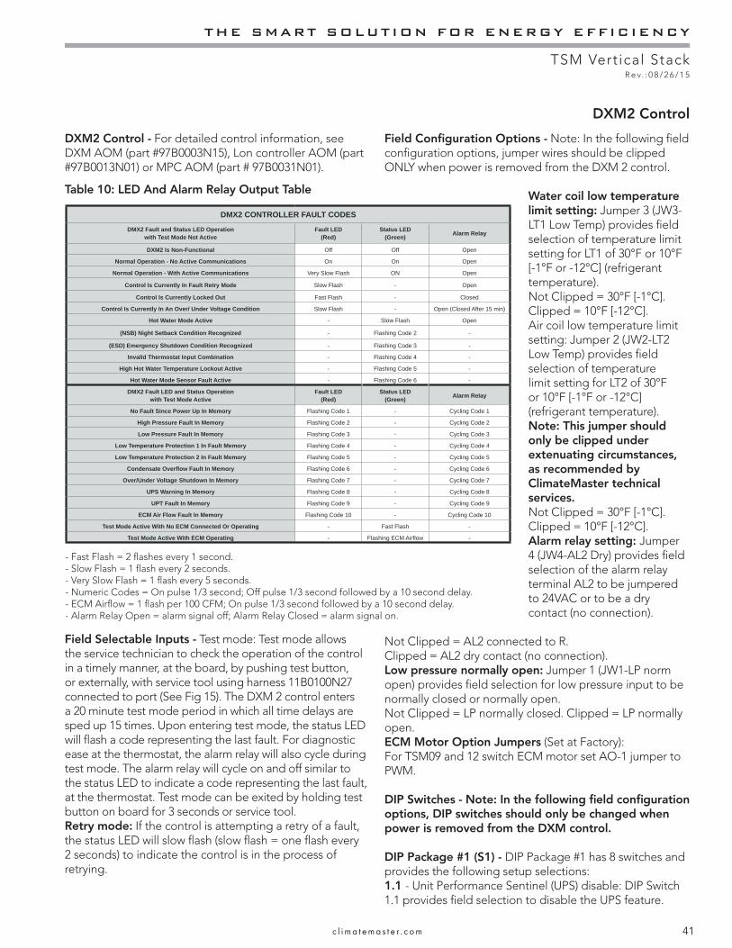
THE SMART SOLUTION FOR ENERGY EFFICIENCY
TSM Vertical StackR e v. : 0 8 / 2 6 / 1 5
41c l i m a t e m a s t e r . c o m
DXM2 Control - For detailed control information, see DXM AOM (part #97B0003N15), Lon controller AOM (part #97B0013N01) or MPC AOM (part # 97B0031N01).
Table 10: LED And Alarm Relay Output Table
Field Selectable Inputs - Test mode: Test mode allows the service technician to check the operation of the control in a timely manner, at the board, by pushing test button, or externally, with service tool using harness 11B0100N27 connected to port (See Fig 15). The DXM 2 control enters a 20 minute test mode period in which all time delays are sped up 15 times. Upon entering test mode, the status LED will fl ash a code representing the last fault. For diagnostic ease at the thermostat, the alarm relay will also cycle during test mode. The alarm relay will cycle on and off similar to the status LED to indicate a code representing the last fault, at the thermostat. Test mode can be exited by holding test button on board for 3 seconds or service tool.Retry mode: If the control is attempting a retry of a fault, the status LED will slow fl ash (slow fl ash = one fl ash every 2 seconds) to indicate the control is in the process of retrying.
Field Confi guration Options - Note: In the following fi eld confi guration options, jumper wires should be clipped ONLY when power is removed from the DXM 2 control.
Water coil low temperature limit setting: Jumper 3 (JW3-LT1 Low Temp) provides fi eld selection of temperature limit setting for LT1 of 30°F or 10°F [-1°F or -12°C] (refrigerant temperature).Not Clipped = 30°F [-1°C]. Clipped = 10°F [-12°C].Air coil low temperature limit setting: Jumper 2 (JW2-LT2 Low Temp) provides fi eld selection of temperature limit setting for LT2 of 30°F or 10°F [-1°F or -12°C] (refrigerant temperature). Note: This jumper should only be clipped under extenuating circumstances, as recommended by ClimateMaster technical services.Not Clipped = 30°F [-1°C]. Clipped = 10°F [-12°C].Alarm relay setting: Jumper 4 (JW4-AL2 Dry) provides fi eld selection of the alarm relay terminal AL2 to be jumpered to 24VAC or to be a dry contact (no connection).
Not Clipped = AL2 connected to R.Clipped = AL2 dry contact (no connection).Low pressure normally open: Jumper 1 (JW1-LP norm open) provides fi eld selection for low pressure input to be normally closed or normally open.Not Clipped = LP normally closed. Clipped = LP normally open. ECM Motor Option Jumpers (Set at Factory):For TSM09 and 12 switch ECM motor set AO-1 jumper to PWM.
DIP Switches - Note: In the following fi eld confi guration options, DIP switches should only be changed when power is removed from the DXM control.
DIP Package #1 (S1) - DIP Package #1 has 8 switches and provides the following setup selections:1.1 - Unit Performance Sentinel (UPS) disable: DIP Switch 1.1 provides fi eld selection to disable the UPS feature.
DXM2 Control
DMX2 CONTROLLER FAULT CODES
DMX2 Fault and Status LED Operation with Test Mode Not Active
Fault LED(Red)
Status LED(Green) Alarm Relay
DXM2 Is Non-Functional Off Off Open
Normal Operation - No Active Communications On On Open
Normal Operation - With Active Communications Very Slow Flash ON Open
Control Is Currently In Fault Retry Mode Slow Flash - Open
Control Is Currently Locked Out Fast Flash - Closed
Control Is Currently In An Over/ Under Voltage Condition Slow Flash - Open (Closed After 15 min)
Hot Water Mode Active - Slow Flash Open
(NSB) Night Setback Condition Recognized - Flashing Code 2 -
(ESD) Emergency Shutdown Condition Recognized - Flashing Code 3 -
Invalid Thermostat Input Combination - Flashing Code 4 -
High Hot Water Temperature Lockout Active - Flashing Code 5 -
Hot Water Mode Sensor Fault Active - Flashing Code 6 -
DMX2 Fault LED and Status Operation with Test Mode Active
Fault LED(Red)
Status LED(Green) Alarm Relay
No Fault Since Power Up In Memory Flashing Code 1 - Cycling Code 1
High Pressure Fault In Memory Flashing Code 2 - Cycling Code 2
Low Pressure Fault In Memory Flashing Code 3 - Cycling Code 3
Low Temperature Protection 1 In Fault Memory Flashing Code 4 - Cycling Code 4
Low Temperature Protection 2 In Fault Memory Flashing Code 5 - Cycling Code 5
Condensate Overfl ow Fault In Memory Flashing Code 6 - Cycling Code 6
Over/Under Voltage Shutdown In Memory Flashing Code 7 - Cycling Code 7
UPS Warning In Memory Flashing Code 8 - Cycling Code 8
UPT Fault In Memory Flashing Code 9 - Cycling Code 9
ECM Air Flow Fault In Memory Flashing Code 10 - Cycling Code 10
Test Mode Active With No ECM Connected Or Operating - Fast Flash -
Test Mode Active With ECM Operating - Flashing ECM Airfl ow -
- Fast Flash = 2 fl ashes every 1 second.- Slow Flash = 1 fl ash every 2 seconds.- Very Slow Flash = 1 fl ash every 5 seconds.- Numeric Codes = On pulse 1/3 second; Off pulse 1/3 second followed by a 10 second delay.- ECM Airfl ow = 1 fl ash per 100 CFM; On pulse 1/3 second followed by a 10 second delay.- Alarm Relay Open = alarm signal off; Alarm Relay Closed = alarm signal on.

CLIMATEMASTER WATER-SOURCE HEAT PUMPS
TSM Vertical StackR e v. : 0 8 / 2 6 / 1 5
42 C l i m a t e M a s t e r Wa t e r - S o u r c e H e a t P u m p s
On = Enabled. Off = Disabled.1.2 - Compressor relay staging operation: DIP 1.2 provides selection of compressor relay staging operation. The compressor relay can be selected to turn on with a stage 1 or stage 2 call from the thermostat. This is used with dual stage units (2 compressors where 2 DXM 2 controls are being used) or with master/slave applications. In master/slave applications, each compressor and fan will stage according to its appropriate DIP 1.2 setting. If set to stage 2, the compressor will have a 3 second on-delay before energizing during a Stage 2 demand. Also, if set for stage 2, the alarm relay will NOT cycle during test mode.On = Stage 1. Off = Stage 2.1.3 - Thermostat type (heat pump or heat/cool): DIP 1.3 provides selection of thermostat type. Heat pump or heat/cool thermostats can be selected. When in heat/cool mode, Y1 is the input call for cooling stage 1; Y2 is the input call for cooling stage 2; W1 is the input call for heating stage 1; and O/W2 is the input call for heating stage 2. In heat pump mode, Y1 is the input call for compressor stage 1; Y2 is the input call for compressor stage 2; W1 is the input call for heating stage 3 or emergency heat; and O/W2 is the input call for reversing valve (heating or cooling, depending upon DIP 1.4).On = Heat Pump. Off = Heat/Cool.1.4 - Thermostat type (O/B): DIP 1.4 provides selection of thermostat type for reversing valve activation. Heat pump thermostats with “O” output (reversing valve energized for cooling) or “B” output (reversing valve energized for heating) can be selected with DIP 1.4. On = HP stat with “O” output for cooling. Off = HP stat with “B” output for heating.1.5 - Dehumidifi cation mode: DIP 1.5 provides selection of normal or dehumidifi cation fan mode. In dehumidifi cation mode, the fan speed relay will remain off during cooling stage 2. In normal mode, the fan speed relay will turn on during cooling stage 2.On = Normal fan mode. Off = Dehumidifi cation mode.1.6 - DDC output at EH2: DIP 1.6 provides selection for DDC operation. If set to “DDC Output at EH2,” the EH2 terminal will continuously output the last fault code of the controller. If set to “EH2 normal,” EH2 will operate as standard electric heat output.On = EH2 Normal. Off = DDC Output at EH2.1.7 - Boilerless operation: DIP 1.7 provides selection of boilerless operation. In boilerless mode, the compressor is only used for heating when LT1 is above the temperature specifi ed by the setting of DIP 1.8. Below DIP 1.8 setting, the compressor is not used and the control goes into emergency heat mode, staging on EH1 and EH2 to provide heating. On = normal. Off = Boilerless operation.1.8 - Boilerless changeover temperature: DIP 1.8 provides selection of boilerless changeover temperature setpoint.
DIP 2.1 DIP 2.2 DIP 2.3 ACC1 Relay OptionOn On On Cycle with fanOff On On Digital NSBOn Off On Water Valve - slow openingOn On Off OADOff Off Off Reheat Option - HumidistatOff On Off Reheat Option - Dehumidistat
DIP 2.4 DIP 2.5 DIP 2.6 ACC2 Relay OptionOn On On Cycle with compressorOff On On Digital NSBOn Off On Water Valve - slow openingOn On Off OAD
All other DIP combinations are invalid
Table 8: Accessory DIP Switch Settings
Note that the LT1 thermistor is sensing refrigerant temperature between the coaxial heat exchanger and the expansion device (TXV). Therefore, the 50°F [10°C] setting is not 50°F [10°C] water, but approximately 60°F [16°C] EWT.On = 50°F [10°C]. Off = 40°F [16°C].
DIP Package #2 (S2) - DIP Package #2 has 8 switches and provides the following setup selections:2.1 - Accessory1 relay personality: DIP 2.1 provides selection of ACC1 relay personality (relay operation/characteristics). See table 9 for description of functionality. 2.2 - Accessory1 relay personality: DIP 2.2 provides selection of ACC 1 relay personality (relay operation/characteristics). See table 9 for description of functionality.2.3 - Accessory1 relay personality: DIP 2.3 provides selection of ACC 1 relay options. See table 11 for description of functionality.2.4 - Accessory2 relay personality: DIP 2.4 provides
selection of ACC 2 relay personality (relay operation/characteristics). See table9 for description of functionality. 2.5 - Accessory2 relay personality: DIP 2.5 provides selection of ACC 2 relay personality (relay operation/characteristics). See table 9 for description of functionality.2.6 - Accessory2 relay personality: DIP 2.6 provides selection of ACC 2 relay options. See table 9 for description of functionality.
DIP Package #3 (S3) - Currently not used for TSM.
2.7 - Auto dehumidifi cation fan mode or high fan mode: DIP 2.7 provides selection of auto dehumidifi cation fan mode or high fan mode. In auto dehumidifi cation mode, the fan speed relay will remain off during cooling stage 2 IF the H input is active. In high fan mode, the fan enable and fan speed relays will turn on when the H input is active.On = Auto dehumidifi cation mode. Off = High fan mode.2.8 - Special factory selection: DIP 2.8 provides special factory selection. Normal position is “On”. Do not change selection unless instructed to do so by the factory.
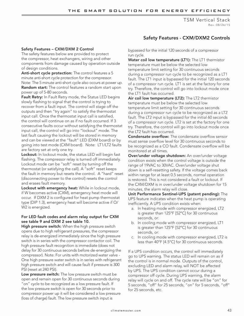
THE SMART SOLUTION FOR ENERGY EFFICIENCY
TSM Vertical StackR e v. : 0 8 / 2 6 / 1 5
43c l i m a t e m a s t e r . c o m
Safety Features – CXM/DXM 2 ControlThe safety features below are provided to protect the compressor, heat exchangers, wiring and other components from damage caused by operation outside of design conditions.Anti-short cycle protection: The control features a 5 minute anti-short cycle protection for the compressor.Note: The 5 minute anti-short cycle also occurs at power up.Random start: The control features a random start upon power up of 5-80 seconds.Fault Retry: In Fault Retry mode, the Status LED begins slowly fl ashing to signal that the control is trying to recover from a fault input. The control will stage off the outputs and then “try again” to satisfy the thermostat input call. Once the thermostat input call is satisfi ed, the control will continue on as if no fault occurred. If 3 consecutive faults occur without satisfying the thermostat input call, the control will go into “lockout” mode. The last fault causing the lockout will be stored in memory and can be viewed at the “fault” LED (DXM board) or by going into test mode (CXM board). Note: LT1/LT2 faults are factory set at only one try.Lockout: In lockout mode, the status LED will begin fast fl ashing. The compressor relay is turned off immediately. Lockout mode can be “soft” reset by turning off the thermostat (or satisfying the call). A “soft” reset keeps the fault in memory but resets the control. A “hard” reset (disconnecting power to the control) resets the control and erases fault memory.Lockout with emergency heat: While in lockout mode, if W becomes active (CXM), emergency heat mode will occur. If DXM 2 is confi gured for heat pump thermostat type (DIP 1.3), emergency heat will become active if O/W2 is energized.
For LED fault codes and alarm relay output for CXM see table 9 and DXM 2 see table 10.High pressure switch: When the high pressure switch opens due to high refrigerant pressures, the compressor relay is de-energized immediately since the high pressure switch is in series with the compressor contactor coil. The high pressure fault recognition is immediate (does not delay for 30 continuous seconds before de-energizing the compressor). Note: For units with motorized water valve - One high pressure water switch is in series with refrigerant high pressure switch and will cause fault if pressure is 300 PSI (reset at 240 PSI).Low pressure switch: The low pressure switch must be open and remain open for 30 continuous seconds during “on” cycle to be recognized as a low pressure fault. If the low pressure switch is open for 30 seconds prior to compressor power up it will be considered a low pressure (loss of charge) fault. The low pressure switch input is
bypassed for the initial 120 seconds of a compressor run cycle.Water coil low temperature (LT1): The LT1 thermistor temperature must be below the selected low temperature limit setting for 30 continuous seconds during a compressor run cycle to be recognized as a LT1 fault. The LT1 input is bypassed for the initial 120 seconds of a compressor run cycle. LT1 is set at the factory for one try. Therefore, the control will go into lockout mode once the LT1 fault has occurred.Air coil low temperature (LT2): The LT2 thermistor temperature must be below the selected low temperature limit setting for 30 continuous seconds during a compressor run cycle to be recognized as a LT2 fault. The LT2 input is bypassed for the initial 60 seconds of a compressor run cycle. LT2 is set at the factory for one try. Therefore, the control will go into lockout mode once the LT2 fault has occurred.Condensate overfl ow: The condensate overfl ow sensor must sense overfl ow level for 30 continuous seconds to be recognized as a CO fault. Condensate overfl ow will be monitored at all times.Over/under voltage shutdown: An over/under voltage condition exists when the control voltage is outside the range of 19VAC to 30VAC. Over/under voltage shut down is a self-resetting safety. If the voltage comes back within range for at least 0.5 seconds, normal operation is restored. This is not considered a fault or lockout. If the CXM/DXM is in over/under voltage shutdown for 15 minutes, the alarm relay will close.Unit Performance Sentinel-UPS (patent pending): The UPS feature indicates when the heat pump is operating ineffi ciently. A UPS condition exists when:
a. In heating mode with compressor energized, LT2 is greater than 125°F [52°C] for 30 continuous seconds, or:
b. In cooling mode with compressor energized, LT1 is greater than 125°F [52°C] for 30 continuous seconds, or:
c. In cooling mode with compressor energized, LT2 is less than 40°F [4.5°C] for 30 continuous seconds.
If a UPS condition occurs, the control will immediately go to UPS warning. The status LED will remain on as if the control is in normal mode. Outputs of the control, excluding LED and alarm relay, will NOT be affected by UPS. The UPS condition cannot occur during a compressor off cycle. During UPS warning, the alarm relay will cycle on and off. The cycle rate will be “on” for 5 seconds, “off” for 25 seconds, “on” for 5 seconds, “off” for 25 seconds, etc.
Safety Features - CXM/DXM2 Controls

CLIMATEMASTER WATER-SOURCE HEAT PUMPS
TSM Vertical StackR e v. : 0 8 / 2 6 / 1 5
44 C l i m a t e M a s t e r Wa t e r - S o u r c e H e a t P u m p s
Swapped LT1/LT2 thermistors: During test mode, the control monitors to see if the LT1 and LT2 thermistors are in the appropriate places. If the control is in test mode, the control will lockout with code 9 after 30 seconds if:
a. The compressor is on in the cooling mode and the LT1 sensor is colder than the LT2 sensor, or:
b. The compressor is on in the heating mode and the LT2 sensor is colder than the LT1 sensor.
ESD (DXM2 only): The ESD (Emergency Shut Down) mode can be enabled from an external common signal to terminal ESD to shut down the unit. The green status light will fl ash code 3 when the unit is in ESD mode.
Diagnostic Features - The LED on the CXM board advises the technician of the current status of the CXM control. The LED can display either the current CXM mode or the last fault in memory if in test mode. If there is no fault in memory, the LED will fl ash Code 1 (when in test mode).
The green status LED and red fault LED on the DXM 2 board advise the technician of the current status of the DXM 2 control. The status LED will indicate the current mode that the DXM 2 control is in. The fault LED will ALWAYS fl ash a code representing the LAST fault in memory. If there is no fault in memory, the fault LED will fl ash Code 1. The yellow test LED will turn on when in test mode.
CXM/DXM 2 Control Start-up Operation - The control will not operate until all inputs and safety controls are checked for normal conditions. The compressor will have a 5 minute anti-short cycle delay at power-up. The fi rst time after power-up that there is a call for compressor, the compressor will follow a 5 to 80 second random start delay. After the random start delay and anti-short cycle delay, the compressor relay will be energized. On all subsequent compressor calls, the random start delay is omitted.
DXM2 has 4 sensors that can be read with service tool ACDU02C and harness 17B0100N27 or thermostat ATC32U02C. Sensors are entering and leaving water temperature, leaving air temperature, and discharge line temperature. (See FIG 21)
CAUTION! CAUTION! Do not restart units without inspection and remedy of faulting condition. Equipment damage may occur.
Figure 21: DXM2 Sensor Placement
17B0008N05Leaving Air Temp Sensor(White (2) Wires Connect to DXM2-T4)
17B0030N06Leaving Water Temp Sensor(Yellow (2) Wires Connect to DXM2-T2)
17B0031N04Discharge Line Temp Sensor(Black (2) Wires Connect to DXM2-T6)
17B0030N05Entering Water Temp Sensor(Green (2) Wires Connect to DXM2-T3)
LT1 Water Coil Protector(Grey (2) Wires - Harness to DXM2-LT1)
LT2 Air Coil Protector(Violet (2) Wires - Harness to DXM2-LT2)
Notes:1. Sensors must be positioned on clean
section of copper tube approximately as shown, clamped securely, and completely wrapped (except Leaving Air Sensor - Do Not wrap) with cork tape.
2. All sensors are NTC 10K OHM. To check calibration use resistance table in DXM2 AOM.
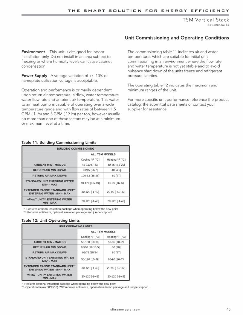
THE SMART SOLUTION FOR ENERGY EFFICIENCY
TSM Vertical StackR e v. : 0 8 / 2 6 / 1 5
45c l i m a t e m a s t e r . c o m
Environment - This unit is designed for indoor installation only. Do not install in an area subject to freezing or where humidity levels can cause cabinet condensation.
Power Supply - A voltage variation of +/- 10% of nameplate utilization voltage is acceptable.
Operation and performance is primarily dependent upon return air temperature, airfl ow, water temperature, water fl ow rate and ambient air temperature. This water to air heat pump is capable of operating over a wide temperature range and with fl ow rates of between 1.5 GPM (.1 l/s) and 3 GPM (.19 l/s) per ton, however usually no more than one of these factors may be at a minimum or maximum level at a time.
The commissioning table 11 indicates air and water temperatures which are suitable for initial unit commissioning in an environment where the fl ow rate and water temperature is not yet stable and to avoid nuisance shut down of the units freeze and refrigerant pressure safeties.
The operating table 12 indicates the maximum and minimum ranges of the unit.
For more specifi c unit performance reference the product catalog, the submittal data sheets or contact your supplier for assistance.
Unit Commissioning and Operating Conditions
Table 11: Building Commissioning LimitsBUILDING COMMISSIONING
ALL TSM MODELS
Cooling °F [°C] Heating °F [°C]
AMBIENT MIN - MAX DB 45-110 [7-43] 40-85 [4.5-29]
RETURN AIR MIN DB/WB 60/45 [16/7] 40 [4.5]
RETURN AIR MAX DB/WB 100-83 [38-28] 80 [27]
STANDARD UNIT ENTERING WATER MIN* - MAX 40-120 [4.5-49] 60-90 [16-43]
EXTENDED RANGE STANDARD UNIT** ENTERING WATER MIN* - MAX 30-120 [-1-49] 20-90 [-6.7-32]
vFlow™ UNIT** ENTERING WATER MIN - MAX 20-120 [-1-49] 20-120 [-1-49]
*- Requires optional insulation package when operating below the dew point**- Requires antifreeze, optional insulation package and jumper clipped.
UNIT OPERATING LIMITS
ALL TSM MODELS
Cooling °F [°C] Heating °F [°C]
AMBIENT MIN - MAX DB 50-100 [10-38] 50-85 [10-29]
RETURN AIR MIN DB/WB 65/60 [18/15.5] 50 [10]
RETURN AIR MAX DB/WB 95/75 [35/24] 80 [27]
STANDARD UNIT ENTERING WATER MIN* - MAX 50-120 [10-49] 60-90 [16-43]
EXTENDED RANGE STANDARD UNIT** ENTERING WATER MIN* - MAX 30-120 [-1-49] 20-90 [-6.7-32]
vFlow™ UNIT** ENTERING WATER MIN - MAX 20-120 [-1-49] 20-120 [-1-49]
*- Requires optional insulation package when operating below the dew point**- Operation below 50°F (10) EWT requires antifreeze, optional insulation package and jumper clipped.
Table 12: Unit Operating Limits
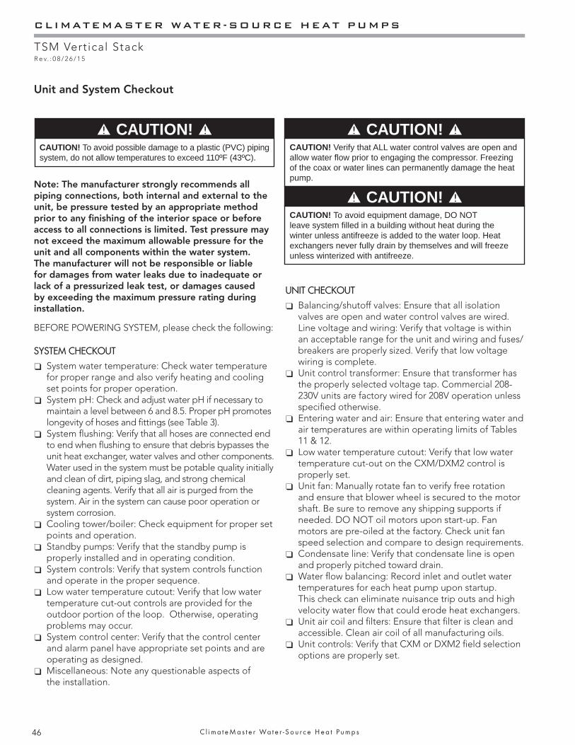
CLIMATEMASTER WATER-SOURCE HEAT PUMPS
TSM Vertical StackR e v. : 0 8 / 2 6 / 1 5
46 C l i m a t e M a s t e r Wa t e r - S o u r c e H e a t P u m p s
CAUTION! To avoid possible damage to a plastic (PVC) piping system, do not allow temperatures to exceed 110ºF (43ºC).
CAUTION!
Note: The manufacturer strongly recommends all piping connections, both internal and external to the unit, be pressure tested by an appropriate method prior to any fi nishing of the interior space or before access to all connections is limited. Test pressure may not exceed the maximum allowable pressure for the unit and all components within the water system. The manufacturer will not be responsible or liable for damages from water leaks due to inadequate or lack of a pressurized leak test, or damages caused by exceeding the maximum pressure rating during installation.
CAUTION! To avoid equipment damage, DO NOT leave system fi lled in a building without heat during the winter unless antifreeze is added to the water loop. Heat exchangers never fully drain by themselves and will freeze unless winterized with antifreeze.
CAUTION!
CAUTION!
Unit and System Checkout
CAUTION! Verify that ALL water control valves are open and allow water fl ow prior to engaging the compressor. Freezing of the coax or water lines can permanently damage the heat pump.
BEFORE POWERING SYSTEM, please check the following:
SYSTEM CHECKOUT System water temperature: Check water temperature for proper range and also verify heating and cooling set points for proper operation.
System pH: Check and adjust water pH if necessary to maintain a level between 6 and 8.5. Proper pH promotes longevity of hoses and fi ttings (see Table 3).
System fl ushing: Verify that all hoses are connected end to end when fl ushing to ensure that debris bypasses the unit heat exchanger, water valves and other components. Water used in the system must be potable quality initially and clean of dirt, piping slag, and strong chemical cleaning agents. Verify that all air is purged from the system. Air in the system can cause poor operation or system corrosion.
Cooling tower/boiler: Check equipment for proper set points and operation.
Standby pumps: Verify that the standby pump is properly installed and in operating condition.
System controls: Verify that system controls function and operate in the proper sequence.
Low water temperature cutout: Verify that low water temperature cut-out controls are provided for the outdoor portion of the loop. Otherwise, operating problems may occur.
System control center: Verify that the control center and alarm panel have appropriate set points and are operating as designed.
Miscellaneous: Note any questionable aspects of the installation.
UNIT CHECKOUT Balancing/shutoff valves: Ensure that all isolation valves are open and water control valves are wired.
Line voltage and wiring: Verify that voltage is within an acceptable range for the unit and wiring and fuses/breakers are properly sized. Verify that low voltage wiring is complete.
Unit control transformer: Ensure that transformer has the properly selected voltage tap. Commercial 208-230V units are factory wired for 208V operation unless specifi ed otherwise.
Entering water and air: Ensure that entering water and air temperatures are within operating limits of Tables 11 & 12.
Low water temperature cutout: Verify that low water temperature cut-out on the CXM/DXM2 control is properly set.
Unit fan: Manually rotate fan to verify free rotation and ensure that blower wheel is secured to the motor shaft. Be sure to remove any shipping supports if needed. DO NOT oil motors upon start-up. Fan motors are pre-oiled at the factory. Check unit fan speed selection and compare to design requirements.
Condensate line: Verify that condensate line is open and properly pitched toward drain.
Water fl ow balancing: Record inlet and outlet water temperatures for each heat pump upon startup. This check can eliminate nuisance trip outs and high velocity water fl ow that could erode heat exchangers.
Unit air coil and fi lters: Ensure that fi lter is clean and accessible. Clean air coil of all manufacturing oils.
Unit controls: Verify that CXM or DXM2 fi eld selection options are properly set.
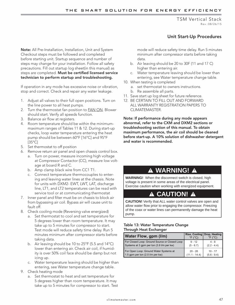
THE SMART SOLUTION FOR ENERGY EFFICIENCY
TSM Vertical StackR e v. : 0 8 / 2 6 / 1 5
47c l i m a t e m a s t e r . c o m
Unit Start-Up Procedures
Note: All Pre-Installation, Installation, Unit and System Checkout steps must be followed and completed before starting unit. Startup sequence and number of steps may change for your installation. Follow all safety precautions. Fill out startup log sheet(in this manual) as steps are completed. Must be certifi ed licensed service technician to perform startup and troubleshooting.
If operation in any mode has excessive noise or vibration, stop and correct. Check and repair any water leakage.
1. Adjust all valves to their full open positions. Turn on the line power to all heat pumps.
2. Turn the thermostat fan position to FAN ON. Blower should start. Verify all speeds function.
3. Balance air fl ow at registers.4. Room temperature should be within the minimum-
maximum ranges of Tables 11 & 12. During start-up checks, loop water temperature entering the heat pump should be between 60°F [16°C] and 95°F [35°C]
5. Set thermostat to off position6. Remove return air panel and open chassis control box.
a. Turn on power, measure incoming high voltage at Compressor Contactor (CC), measure low volt-age at board R and C.
b. Amp clamp black wire from CC1 T1. c. Connect temperature thermocouples to enter-
ing and leaving water lines at the chassis. Note for units with DXM2- EWT, LWT, LAT, discharge line, LT1, and LT2 temperatures can be read with service tool or at communicating thermostat
7. Inner panel and fi lter must be on chassis to block air from bypassing air coil. Bypass air will cause unit to fault off.
8. Check cooling mode (Reversing valve energized) a. Set thermostat to cool and set temperature for
5 degrees lower than room temperature. It may take up to 5 minutes for compressor to start. Test mode will reduce safety time delay. Run 5 minutes minimum after compressor starts before taking data.
b. Air leaving should be 10 to 25°F (5.5 and 14°C) lower than entering air. Check air coil, if humid-ity is over 50% coil face should be damp but not icing up.
c. Water temperature leaving should be higher than entering, see Water temperature change table.
9. Check heating modea. Set thermostat to heat and set temperature for
5 degrees higher than room temperature. It may take up to 5 minutes for compressor to start. Test
mode will reduce safety time delay. Run 5 minutes minimum after compressor starts before taking data.
b. Air leaving should be 20 to 30F (11 and 17 C) higher than entering air.
c. Water temperature leaving should be lower than entering, see Water temperature change table.
10. When testing is completed a. set thermostat to owners instructions. b. Re assemble all parts.
11. Save start up log sheet for future reference.12. BE CERTAIN TO FILL OUT AND FORWARD
ALL WARRANTY REGISTRATION PAPERS TO CLIMATEMASTER.
Note: If performance during any mode appears abnormal, refer to the CXM and DXM2 sections or troubleshooting section of this manual. To obtain maximum performance, the air coil should be cleaned before start-up. A 10% solution of dishwasher detergent and water is recommended.
WARNING! When the disconnect switch is closed, high voltage is present in some areas of the electrical panel. Exercise caution when working with energized equipment.
CAUTION! Verify that ALL water control valves are open and allow water fl ow prior to engaging the compressor. Freezing of the coax or water lines can permanently damage the heat pump.
WARNING!
CAUTION!
Table 13: Water Temperature Change Through Heat Exchanger

CLIMATEMASTER WATER-SOURCE HEAT PUMPS
TSM Vertical StackR e v. : 0 8 / 2 6 / 1 5
48 C l i m a t e M a s t e r Wa t e r - S o u r c e H e a t P u m p s
Notes for Tables 14A - 14G:• Airflow is at nominal (rated) conditions;• Entering air is based upon 70°F [21°C] DB in heating
and 80/67°F [27/19°C] in cooling;
• Subcooling is based upon head pressure at compressor service port;
• Cooling air and water values can vary greatly with changes in humidity level.
Table 14A: TSM09
Table 14B: TSM12
Unit Operating Pressures and Temperatures
Entering Water
Temp ºF
Water Flow GPM
Cooling Heating
Suction Pressure
PSIG
Discharge Pressure
PSIG
Discharge Temp ºF
LT1 Temp ºF
LT2 Temp ºF
Super-heat
Sub-cooling
Water Temp
Rise ºF
Air Temp Drop ºF
DB
Suction Pressure
PSIG
Discharge Pressure
PSIG
Discharge Temp ºF
LT1 Temp ºF
LT2 Temp ºF
Super-heat
Sub-cooling
Water Temp
Drop ºF
Air Temp Rise ºF
DB
201.5
2.253.0 60 - 63 289 - 306 148 - 163 14 - 18 71 - 75 9 - 12 8 - 17 3 - 4 20 - 22
301.5 122 - 125 197 - 204 90 - 105 42 - 46 49 - 53 13 - 16 15 - 20 20 - 24 22 - 23 67 - 71 297 - 315 147 - 162 20 - 24 72 - 76 10 - 12 9 - 18 8 - 9 22 - 23
2.25 116 - 119 177 - 184 86 - 101 38 - 42 48 - 52 17 - 19 15 - 18 13 - 16 21 - 22 71 - 75 301 - 321 146 - 161 22 - 26 73 - 77 10 - 12 10 - 19 6 - 7 23 - 243.0 112 - 115 168 - 173 97 - 112 36 - 40 39 - 43 19 - 21 14 - 18 10 - 12 21 - 22 74 - 76 303 - 323 146 - 161 23 - 27 73 - 77 11 - 13 10 - 19 4 - 5 23 - 25
501.5 128 - 134 240 - 252 107 - 122 62 - 66 51 - 55 11 - 14 13 - 16 20 - 22 21 - 22 97 - 102 333 - 355 139 - 154 37 - 41 77 - 81 9 - 11 13 - 21 11 - 12 29 - 30
2.25 122 - 131 219 - 233 102 - 117 59 - 63 51 - 55 12 - 17 12 - 16 13 - 15 21 - 22 104 - 108 339 - 361 139 - 154 40 - 44 79 - 83 9 - 11 13 - 21 8 - 9 30 - 313.0 119 - 129 209 - 224 104 - 119 58 - 62 47 - 51 13 - 18 11 - 15 10 - 11 21 - 22 107 - 122 342 - 369 139 - 154 41 - 45 79 - 83 9 - 11 13 - 20 6 - 7 31 - 32
701.5 132 - 139 311 - 329 127 - 142 82 - 86 53 - 57 9 - 12 12 - 15 19 - 21 20 - 21 130 - 135 367 - 392 138 - 153 52 - 56 84 - 88 9 - 11 13 - 21 14 - 16 35 - 37
2.25 131 - 137 287 - 306 121 - 136 80 - 84 53 - 57 10 - 13 10 - 12 13 - 14 20 - 21 139 - 144 375 - 402 138 - 153 55 - 59 85 - 89 10 - 11 13 - 20 10 - 12 37 - 383.0 131 - 136 275 - 294 118 - 133 79 - 83 53 - 57 10 - 13 9 - 11 9 - 11 20 - 21 145 - 149 380 - 407 138 - 153 57 - 61 86 - 90 10 - 11 13 - 19 8 - 9 38 - 39
901.5 137 - 144 400 - 420 149 - 164 101 - 105 55 - 59 8 - 10 13 - 16 19 - 20 19 - 20 164 - 169 401 - 430 139 - 154 64 - 68 90 - 94 10 - 13 13 - 17 18 - 20 41 - 43
2.25 135 - 142 373 - 395 142 - 157 99 - 103 55 - 59 9 - 11 10 - 12 12 - 14 19 - 20 175 - 178 411 - 442 141 - 156 68 - 72 92 - 96 12 - 16 14 - 17 12 - 14 43 - 453.0 135 - 141 359 - 383 138 - 153 98 - 102 56 - 60 9 - 12 9 - 11 9 - 10 19 - 20 179 - 187 415 - 455 142 - 157 69 - 73 93 - 97 13 - 18 14 - 16 9 - 11 44 - 46
1001.5 139 - 147 448 - 471 161 - 176 110 - 114 56 - 60 8 - 9 13 - 16 18 - 20 18 - 19
2.25 138 - 146 420 - 445 155 - 170 108 - 112 56 - 60 8 - 10 11 - 13 12 - 13 18 - 193.0 138 - 146 405 - 432 151 - 166 108 - 112 57 - 61 8 - 10 10 - 11 9 - 10 18 - 19
1201.5 144 - 153 549 - 583 186 - 201 128 - 132 58 - 62 7 - 8 15 - 17 17 - 19 17 - 18
2.25 143 - 153 525 - 557 181 - 196 126 - 130 58 - 62 7 - 8 12 - 14 11 - 13 17 - 183.0 143 - 152 511 - 543 180 - 195 126 - 130 57 - 61 8 - 9 11 - 13 9 - 10 17 - 18
Entering Water
Temp ºF
Water Flow GPM
Cooling Heating
Suction Pressure
PSIG
Discharge Pressure
PSIG
Discharge Temp ºF
LT1 Temp ºF
LT2 Temp ºF
Super-heat
Sub-cooling
Water Temp
Rise ºF
Air Temp Drop ºF
DB
Suction Pressure
PSIG
Discharge Pressure
PSIG
Discharge Temp ºF
LT1 Temp ºF
LT2 Temp ºF
Super-heat
Sub-cooling
Water Temp
Drop ºF
Air Temp Rise ºF
DB
201.5
2.253.0 60 - 63 289 - 306 151 - 166 13 - 17 72 - 76 9 - 12 8 - 17 3 - 4 20 - 22
301.5 122 - 125 197 - 204 82 - 97 40 - 44 45 - 49 13 - 16 15 - 20 20 - 24 22 - 23 67 - 71 297 - 315 153 - 168 18 - 22 73 - 77 10 - 12 9 - 18 8 - 9 22 - 23
2.25 116 - 119 177 - 184 77 - 92 37 - 41 44 - 48 17 - 19 15 - 18 13 - 16 21 - 22 71 - 75 301 - 321 151 - 166 21 - 25 74 - 78 10 - 12 10 - 19 6 - 7 23 - 243.0 112 - 115 168 - 173 89 - 104 36 - 40 38 - 42 19 - 21 14 - 18 10 - 12 21 - 22 74 - 76 303 - 323 151 - 166 22 - 26 74 - 78 11 - 13 10 - 19 4 - 5 23 - 25
501.5 128 - 134 240 - 252 103 - 118 59 - 63 48 - 52 11 - 14 13 - 16 20 - 22 21 - 22 97 - 102 333 - 355 145 - 160 35 - 39 78 - 82 9 - 11 13 - 21 11 - 12 29 - 30
2.25 122 - 131 219 - 233 97 - 112 57 - 61 47 - 51 12 - 17 12 - 16 13 - 15 21 - 22 104 - 108 339 - 361 144 - 159 39 - 43 79 - 83 9 - 11 13 - 21 8 - 9 30 - 313.0 119 - 129 209 - 224 100 - 115 56 - 60 45 - 49 13 - 18 11 - 15 10 - 11 21 - 22 107 - 122 342 - 369 143 - 158 40 - 44 80 - 84 9 - 11 13 - 20 6 - 7 31 - 32
701.5 132 - 139 311 - 329 125 - 139 78 - 82 51 - 55 9 - 12 12 - 15 19 - 21 20 - 21 130 - 135 367 - 392 141 - 156 52 - 56 86 - 90 9 - 11 13 - 21 14 - 16 35 - 37
2.25 131 - 137 287 - 306 119 - 134 76 - 80 50 - 54 10 - 13 10 - 12 13 - 14 20 - 21 139 - 144 375 - 402 141 - 156 56 - 60 88 - 92 10 - 11 13 - 20 10 - 12 37 - 383.0 131 - 136 275 - 294 115 - 130 75 - 79 50 - 54 10 - 13 9 - 11 9 -11 20 - 21 145 - 149 380 - 407 141 - 156 58 - 62 90 - 94 10 - 11 13 - 19 8 - 9 38 - 39
901.5 137 - 144 400 - 420 147 - 162 98 - 102 53 - 57 8 - 10 13 - 16 19 - 20 19 - 20 164 - 169 401 - 430 143 - 158 65 - 69 94 - 98 10 - 13 13 - 17 18 - 20 41 - 43
2.25 135 - 142 373 - 395 141 - 156 96 - 100 53 - 57 9 - 11 10 - 12 12 - 14 19 - 20 175 - 178 411 - 442 143 - 158 70 - 74 99 - 103 12 - 16 14 - 17 12 - 14 43 - 453.0 135 - 141 359 - 383 136 - 151 95 - 99 54 - 58 9 - 12 9 - 11 9 - 10 19 - 20 179 - 187 415 - 455 143 - 158 73 - 77 101 - 105 13 - 18 14 - 16 9 - 11 44 - 46
1001.5 139 - 147 448 - 471 158 - 173 107 - 111 55 - 59 8 - 9 13 - 16 18 - 20 18 - 19
2.25 138 - 146 420 - 445 152 - 167 105 - 109 54 - 58 8 - 10 11 - 13 12 - 13 18 - 193.0 138 - 146 405 - 432 148 - 163 105 - 109 55 - 59 8 - 10 10 - 11 9 - 10 18 - 19
1201.5 144 - 153 549 - 583 181 - 196 126 - 130 57 - 61 7 - 8 15 - 17 17 - 19 17 - 18
2.25 143 - 153 525 - 557 175 - 190 125 - 129 57 - 61 7 - 8 12 - 14 11 - 13 17 - 183.0 143 - 152 511 - 543 176 - 191 124 - 128 56 - 60 8 - 9 11 - 13 9 - 10 17 - 18
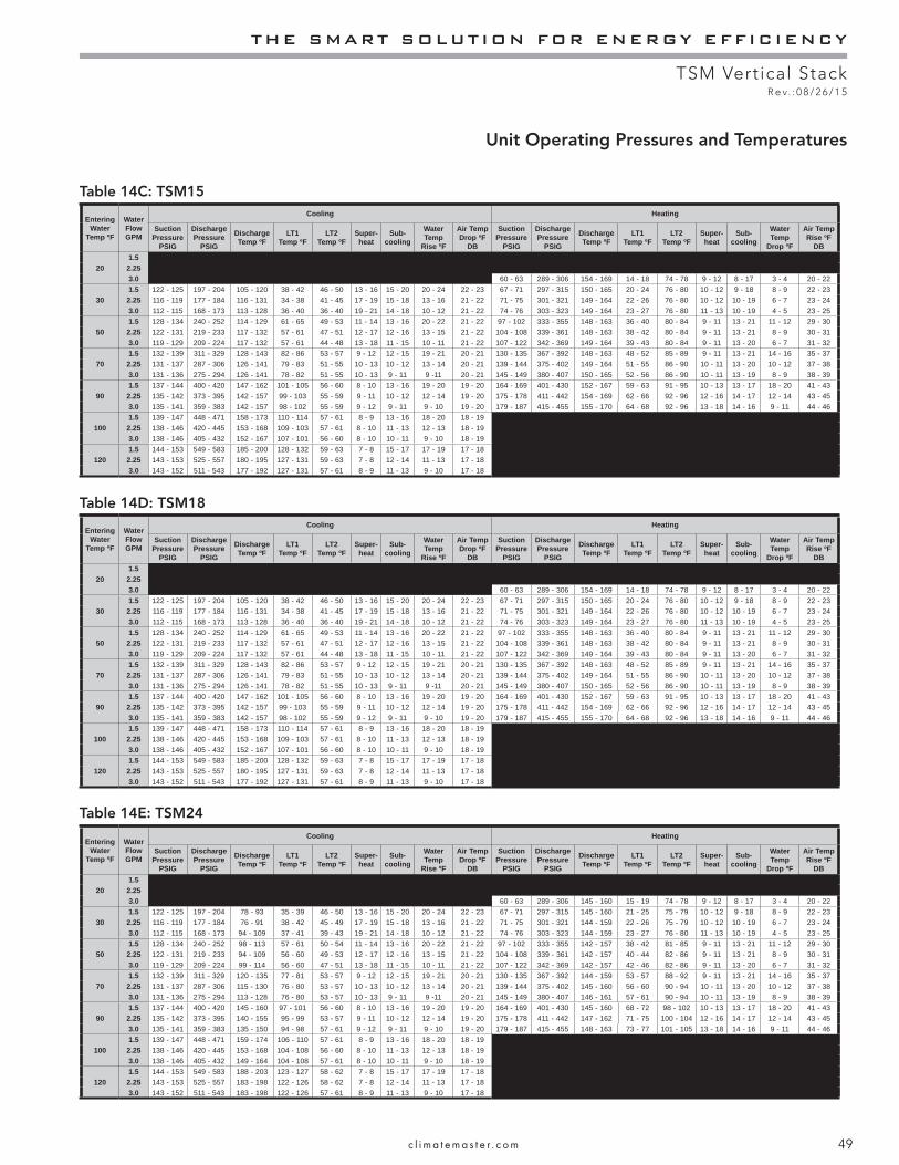
THE SMART SOLUTION FOR ENERGY EFFICIENCY
TSM Vertical StackR e v. : 0 8 / 2 6 / 1 5
49c l i m a t e m a s t e r . c o m
Table 14C: TSM15
Unit Operating Pressures and Temperatures
Table 14D: TSM18
Table 14E: TSM24
Entering Water
Temp ºF
Water Flow GPM
Cooling Heating
Suction Pressure
PSIG
Discharge Pressure
PSIG
Discharge Temp ºF
LT1 Temp ºF
LT2 Temp ºF
Super-heat
Sub-cooling
Water Temp
Rise ºF
Air Temp Drop ºF
DB
Suction Pressure
PSIG
Discharge Pressure
PSIG
Discharge Temp ºF
LT1 Temp ºF
LT2 Temp ºF
Super-heat
Sub-cooling
Water Temp
Drop ºF
Air Temp Rise ºF
DB
201.5
2.253.0 60 - 63 289 - 306 154 - 169 14 - 18 74 - 78 9 - 12 8 - 17 3 - 4 20 - 22
301.5 122 - 125 197 - 204 105 - 120 38 - 42 46 - 50 13 - 16 15 - 20 20 - 24 22 - 23 67 - 71 297 - 315 150 - 165 20 - 24 76 - 80 10 - 12 9 - 18 8 - 9 22 - 23
2.25 116 - 119 177 - 184 116 - 131 34 - 38 41 - 45 17 - 19 15 - 18 13 - 16 21 - 22 71 - 75 301 - 321 149 - 164 22 - 26 76 - 80 10 - 12 10 - 19 6 - 7 23 - 243.0 112 - 115 168 - 173 113 - 128 36 - 40 36 - 40 19 - 21 14 - 18 10 - 12 21 - 22 74 - 76 303 - 323 149 - 164 23 - 27 76 - 80 11 - 13 10 - 19 4 - 5 23 - 25
501.5 128 - 134 240 - 252 114 - 129 61 - 65 49 - 53 11 - 14 13 - 16 20 - 22 21 - 22 97 - 102 333 - 355 148 - 163 36 - 40 80 - 84 9 - 11 13 - 21 11 - 12 29 - 30
2.25 122 - 131 219 - 233 117 - 132 57 - 61 47 - 51 12 - 17 12 - 16 13 - 15 21 - 22 104 - 108 339 - 361 148 - 163 38 - 42 80 - 84 9 - 11 13 - 21 8 - 9 30 - 313.0 119 - 129 209 - 224 117 - 132 57 - 61 44 - 48 13 - 18 11 - 15 10 - 11 21 - 22 107 - 122 342 - 369 149 - 164 39 - 43 80 - 84 9 - 11 13 - 20 6 - 7 31 - 32
701.5 132 - 139 311 - 329 128 - 143 82 - 86 53 - 57 9 - 12 12 - 15 19 - 21 20 - 21 130 - 135 367 - 392 148 - 163 48 - 52 85 - 89 9 - 11 13 - 21 14 - 16 35 - 37
2.25 131 - 137 287 - 306 126 - 141 79 - 83 51 - 55 10 - 13 10 - 12 13 - 14 20 - 21 139 - 144 375 - 402 149 - 164 51 - 55 86 - 90 10 - 11 13 - 20 10 - 12 37 - 383.0 131 - 136 275 - 294 126 - 141 78 - 82 51 - 55 10 - 13 9 - 11 9 -11 20 - 21 145 - 149 380 - 407 150 - 165 52 - 56 86 - 90 10 - 11 13 - 19 8 - 9 38 - 39
901.5 137 - 144 400 - 420 147 - 162 101 - 105 56 - 60 8 - 10 13 - 16 19 - 20 19 - 20 164 - 169 401 - 430 152 - 167 59 - 63 91 - 95 10 - 13 13 - 17 18 - 20 41 - 43
2.25 135 - 142 373 - 395 142 - 157 99 - 103 55 - 59 9 - 11 10 - 12 12 - 14 19 - 20 175 - 178 411 - 442 154 - 169 62 - 66 92 - 96 12 - 16 14 - 17 12 - 14 43 - 453.0 135 - 141 359 - 383 142 - 157 98 - 102 55 - 59 9 - 12 9 - 11 9 - 10 19 - 20 179 - 187 415 - 455 155 - 170 64 - 68 92 - 96 13 - 18 14 - 16 9 - 11 44 - 46
1001.5 139 - 147 448 - 471 158 - 173 110 - 114 57 - 61 8 - 9 13 - 16 18 - 20 18 - 19
2.25 138 - 146 420 - 445 153 - 168 109 - 103 57 - 61 8 - 10 11 - 13 12 - 13 18 - 193.0 138 - 146 405 - 432 152 - 167 107 - 101 56 - 60 8 - 10 10 - 11 9 - 10 18 - 19
1201.5 144 - 153 549 - 583 185 - 200 128 - 132 59 - 63 7 - 8 15 - 17 17 - 19 17 - 18
2.25 143 - 153 525 - 557 180 - 195 127 - 131 59 - 63 7 - 8 12 - 14 11 - 13 17 - 183.0 143 - 152 511 - 543 177 - 192 127 - 131 57 - 61 8 - 9 11 - 13 9 - 10 17 - 18
Entering Water
Temp ºF
Water Flow GPM
Cooling Heating
Suction Pressure
PSIG
Discharge Pressure
PSIG
Discharge Temp ºF
LT1 Temp ºF
LT2 Temp ºF
Super-heat
Sub-cooling
Water Temp
Rise ºF
Air Temp Drop ºF
DB
Suction Pressure
PSIG
Discharge Pressure
PSIG
Discharge Temp ºF
LT1 Temp ºF
LT2 Temp ºF
Super-heat
Sub-cooling
Water Temp
Drop ºF
Air Temp Rise ºF
DB
201.5
2.253.0 60 - 63 289 - 306 145 - 160 15 - 19 74 - 78 9 - 12 8 - 17 3 - 4 20 - 22
301.5 122 - 125 197 - 204 78 - 93 35 - 39 46 - 50 13 - 16 15 - 20 20 - 24 22 - 23 67 - 71 297 - 315 145 - 160 21 - 25 75 - 79 10 - 12 9 - 18 8 - 9 22 - 23
2.25 116 - 119 177 - 184 76 - 91 38 - 42 45 - 49 17 - 19 15 - 18 13 - 16 21 - 22 71 - 75 301 - 321 144 - 159 22 - 26 75 - 79 10 - 12 10 - 19 6 - 7 23 - 243.0 112 - 115 168 - 173 94 - 109 37 - 41 39 - 43 19 - 21 14 - 18 10 - 12 21 - 22 74 - 76 303 - 323 144 - 159 23 - 27 76 - 80 11 - 13 10 - 19 4 - 5 23 - 25
501.5 128 - 134 240 - 252 98 - 113 57 - 61 50 - 54 11 - 14 13 - 16 20 - 22 21 - 22 97 - 102 333 - 355 142 - 157 38 - 42 81 - 85 9 - 11 13 - 21 11 - 12 29 - 30
2.25 122 - 131 219 - 233 94 - 109 56 - 60 49 - 53 12 - 17 12 - 16 13 - 15 21 - 22 104 - 108 339 - 361 142 - 157 40 - 44 82 - 86 9 - 11 13 - 21 8 - 9 30 - 313.0 119 - 129 209 - 224 99 - 114 56 - 60 47 - 51 13 - 18 11 - 15 10 - 11 21 - 22 107 - 122 342 - 369 142 - 157 42 - 46 82 - 86 9 - 11 13 - 20 6 - 7 31 - 32
701.5 132 - 139 311 - 329 120 - 135 77 - 81 53 - 57 9 - 12 12 - 15 19 - 21 20 - 21 130 - 135 367 - 392 144 - 159 53 - 57 88 - 92 9 - 11 13 - 21 14 - 16 35 - 37
2.25 131 - 137 287 - 306 115 - 130 76 - 80 53 - 57 10 - 13 10 - 12 13 - 14 20 - 21 139 - 144 375 - 402 145 - 160 56 - 60 90 - 94 10 - 11 13 - 20 10 - 12 37 - 383.0 131 - 136 275 - 294 113 - 128 76 - 80 53 - 57 10 - 13 9 - 11 9 -11 20 - 21 145 - 149 380 - 407 146 - 161 57 - 61 90 - 94 10 - 11 13 - 19 8 - 9 38 - 39
901.5 137 - 144 400 - 420 145 - 160 97 - 101 56 - 60 8 - 10 13 - 16 19 - 20 19 - 20 164 - 169 401 - 430 145 - 160 68 - 72 98 - 102 10 - 13 13 - 17 18 - 20 41 - 43
2.25 135 - 142 373 - 395 140 - 155 95 - 99 53 - 57 9 - 11 10 - 12 12 - 14 19 - 20 175 - 178 411 - 442 147 - 162 71 - 75 100 - 104 12 - 16 14 - 17 12 - 14 43 - 453.0 135 - 141 359 - 383 135 - 150 94 - 98 57 - 61 9 - 12 9 - 11 9 - 10 19 - 20 179 - 187 415 - 455 148 - 163 73 - 77 101 - 105 13 - 18 14 - 16 9 - 11 44 - 46
1001.5 139 - 147 448 - 471 159 - 174 106 - 110 57 - 61 8 - 9 13 - 16 18 - 20 18 - 19
2.25 138 - 146 420 - 445 153 - 168 104 - 108 56 - 60 8 - 10 11 - 13 12 - 13 18 - 193.0 138 - 146 405 - 432 149 - 164 104 - 108 57 - 61 8 - 10 10 - 11 9 - 10 18 - 19
1201.5 144 - 153 549 - 583 188 - 203 123 - 127 58 - 62 7 - 8 15 - 17 17 - 19 17 - 18
2.25 143 - 153 525 - 557 183 - 198 122 - 126 58 - 62 7 - 8 12 - 14 11 - 13 17 - 183.0 143 - 152 511 - 543 183 - 198 122 - 126 57 - 61 8 - 9 11 - 13 9 - 10 17 - 18
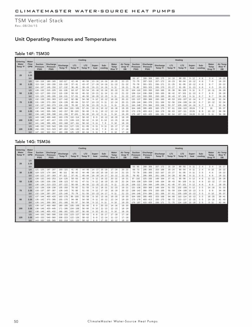
CLIMATEMASTER WATER-SOURCE HEAT PUMPS
TSM Vertical StackR e v. : 0 8 / 2 6 / 1 5
50 C l i m a t e M a s t e r Wa t e r - S o u r c e H e a t P u m p s
Table 14F: TSM30
Table 14G: TSM36
Unit Operating Pressures and Temperatures
Entering Water
Temp ºF
Water Flow GPM
Cooling Heating
Suction Pressure
PSIG
Discharge Pressure
PSIG
Discharge Temp ºF
LT1 Temp ºF
LT2 Temp ºF
Super-heat
Sub-cooling
Water Temp
Rise ºF
Air Temp Drop ºF
DB
Suction Pressure
PSIG
Discharge Pressure
PSIG
Discharge Temp ºF
LT1 Temp ºF
LT2 Temp ºF
Super-heat
Sub-cooling
Water Temp
Drop ºF
Air Temp Rise ºF
DB
201.5
2.253.0 63 - 67 289 - 306 160 - 175 14 - 18 89 - 93 9 - 12 4 - 6 3 - 4 18 - 20
301.5 116 - 118 160 - 165 102 -117 42 - 46 46 - 50 13 - 16 14 - 16 18 - 20 22 - 23 72 - 75 297 - 315 157 - 172 19 - 23 90 - 94 10 - 12 4 - 6 7 - 9 19 - 20
2.25 113 - 116 150 - 155 115 - 130 37 - 41 43 - 47 17 - 19 14 - 16 11 - 13 21 - 22 75 - 78 301 - 321 156 - 171 21 - 25 91 - 95 10 - 12 4 - 6 6 - 7 20 - 223.0 104 - 107 145 - 150 117 - 132 36 - 40 39 - 43 19 - 21 14 - 16 9 - 11 19 - 21 78 - 82 303 - 323 155 - 170 23 - 27 91 - 95 11 - 13 4 - 6 4 - 5 20 - 22
501.5 128 - 132 215 - 225 111 - 126 63 - 67 50 - 54 15 - 18 13 - 16 20 - 22 21 - 22 104 - 110 333 - 355 150 - 165 35 - 39 96 - 100 9 - 11 6 - 7 10 - 11 26 - 28
2.25 122 - 127 200 - 210 115 - 130 59 - 63 48 - 52 19 - 21 11 - 14 11 - 13 21 - 22 108 - 114 336 - 358 150 - 165 38 - 42 97 - 101 11 - 13 6 - 7 8 - 9 26 - 283.0 119 - 125 195 - 205 116 - 131 57 - 61 46 - 50 18 - 20 12 - 15 9 - 11 21 - 22 107 - 113 333 - 355 150 - 165 39 - 43 97 - 101 9 - 11 6 - 7 6 - 7 26 - 28
701.5 132 - 139 293 - 303 127 - 142 82 - 86 54 - 58 9 - 12 10 - 12 18 - 20 20 - 21 132 - 137 359 - 369 150 - 165 49 - 53 103 - 107 12 - 14 6 - 7 14 - 16 32 - 34
2.25 131 - 136 273 - 283 124 - 139 80 - 84 53 - 57 10 - 13 9 - 11 12 - 14 20 - 21 139 - 144 366 - 376 151 - 166 52 - 56 104 - 108 14 - 16 6 - 7 10 - 12 32 - 343.0 132 - 137 263 - 273 124 - 139 78 - 82 52 - 56 13 - 15 9 - 11 9 - 11 20 - 21 144 - 148 374 - 384 153 - 168 53 - 57 105 - 109 14 - 16 6 - 7 8 - 9 32 - 34
901.5 137 - 144 358 - 368 149 - 164 101 - 105 57 - 61 10 - 11 10 - 12 16 - 18 19 - 20 164 - 169 395 - 405 160 - 175 57 - 61 106 - 110 20-24 7 - 8 16 35 - 37
2.25 136 - 142 335 - 345 142 - 157 99 - 103 56 - 60 9 - 11 10 - 12 12 - 14 19 - 20 173 - 178 403 - 413 164 - 179 59 - 63 107 - 111 22-26 8 - 9 10 - 12 36 - 383.0 134 - 140 328 - 338 141 - 156 97 -101 56 - 60 10 - 12 9 - 11 9 - 10 19 - 20 179 - 187 415 - 425 166 - 181 60 - 64 107 - 111 24-28 9 - 10 9 - 11 36 - 38
1001.5 143 - 148 430 - 440 163 - 178 110 - 114 58 - 62 8 - 9 10 - 12 18 - 20 18 - 19
2.25 142 - 147 407 - 417 155 - 170 109 - 113 58 - 62 8 - 10 8 - 10 13 - 15 18 - 193.0 141 - 146 395 - 405 153 - 168 107 - 111 58 - 62 9 - 11 7 - 9 9 - 10 18 - 19
1201.5 148 - 152 533 - 543 195 - 210 127 - 131 61 - 65 9 - 11 9 - 11 15 - 17 17 - 18
2.25 150 - 155 513 - 523 187 - 202 126 - 130 61 - 65 8 - 10 7 - 9 10 - 12 17 - 183.0 147 - 152 502 - 512 183 - 198 125 - 129 60 - 64 9 - 11 7 - 9 8 - 10 17 - 18
Entering Water
Temp ºF
Water Flow GPM
Cooling Heating
Suction Pressure
PSIG
Discharge Pressure
PSIG
Discharge Temp ºF
LT1 Temp ºF
LT2 Temp ºF
Super-heat
Sub-cooling
Water Temp
Rise ºF
Air Temp Drop ºF
DB
Suction Pressure
PSIG
Discharge Pressure
PSIG
Discharge Temp ºF
LT1 Temp ºF
LT2 Temp ºF
Super-heat
Sub-cooling
Water Temp
Drop ºF
Air Temp Rise ºF
DB
201.5
2.253.0 63 - 65 289 - 306 157 - 172 15 - 19 89 - 93 8 - 11 2 - 4 3 - 4 15 - 17
301.5 121 - 125 197 - 207 100 - 115 41 - 45 44 - 48 14 - 17 15 - 18 17 - 19 20 - 22 69 - 73 295 - 305 153 - 168 20 - 24 90 - 94 8 - 11 2 - 4 8 - 10 20 - 22
2.25 119 - 123 174 - 184 96 - 111 38 - 42 44 - 48 16 - 19 15 - 18 12 - 14 21 - 23 73 - 76 295 - 305 152 - 167 23 - 27 91 - 95 8 - 11 3 - 5 4 - 6 19 - 223.0 118 - 122 157 - 163 97 - 112 37 - 41 40 - 44 16 - 19 14 - 17 10 - 12 22 - 25 78 - 82 295 - 305 151 - 166 24 - 28 92 - 96 8 - 11 3 - 5 4 - 6 19 - 22
501.5 128 - 132 243 - 253 114 - 129 59 - 63 48 - 52 9 - 12 19 - 22 20 - 22 19 - 21 97 - 102 325 - 335 149 - 164 37 - 41 95 - 99 9 - 12 4 - 6 11 - 13 26 - 28
2.25 126 - 130 226 - 236 108 - 123 57 - 61 47 - 51 9 - 12 16 - 19 15 - 19 22 - 24 104 - 108 329 - 339 149 - 164 39 - 43 96 - 100 8 - 11 4 - 6 10 - 12 17 - 193.0 130 - 134 213 - 223 107 - 122 56 - 60 46 - 50 12 - 15 12 - 15 9 - 11 22 - 24 108 - 112 334 - 344 149 - 164 41 - 45 97 - 101 9 - 12 4 - 6 6 - 8 28 - 30
701.5 132 - 136 228 - 238 135 - 150 78 - 82 51 - 55 9 - 12 18 - 21 21 - 23 19 - 21 131 - 136 359 - 369 149 - 164 51 - 55 102 - 106 9 - 12 3 - 5 14 - 16 31 - 33
2.25 133 - 137 297 - 307 128 - 143 76 - 80 51 - 55 9 - 12 17 - 19 16 - 19 20 - 22 138 - 142 366 - 376 150 - 165 55 - 59 104 - 108 10 - 13 3 - 5 6 - 8 34 - 363.0 132 - 134 287 - 297 125 - 140 75 - 79 51 - 55 10 - 13 14 - 17 9 - 11 21 - 23 144 - 148 374 - 384 151 - 166 57 - 61 105 - 109 10 - 13 3 - 5 8 - 10 35 - 37
901.5 137 - 144 400 - 420 163 - 178 96 - 100 55 - 59 8 - 10 13 - 16 19 - 20 19 - 20 164 - 169 395 - 405 153 - 168 64 - 68 110 - 114 10 - 13 3 - 5 18 - 20 39 - 41
2.25 135 - 142 373 - 395 155 - 170 94 - 98 54 - 58 9 - 11 10 - 12 12 - 14 19 - 20 173 - 178 403 - 413 155 - 170 68 - 72 113 - 117 12 - 15 3 - 5 14 - 16 41 - 433.0 135 - 141 359 - 383 151 - 166 93 - 97 54 - 58 9 - 12 9 - 11 9 - 10 19 - 20 179 - 187 415 - 425 156 - 171 71 - 75 114 - 118 13 - 18 3 - 5 9 - 11 42 - 44
1001.5 139 - 147 450 - 460 180 - 195 105 - 109 56 - 60 8 - 9 20 - 23 14 - 16 19 - 20
2.25 138 - 146 420 - 445 171 - 186 104 - 108 56 - 60 8 - 10 11 - 13 12 - 13 18 - 193.0 138 - 146 405 - 432 166 - 181 103 - 107 56 - 60 8 - 10 10 - 11 9 - 10 18 - 19
1201.5 144 - 153 560 - 590 218 - 233 123 - 127 59 - 63 6 - 8 15 - 17 17 - 19 17 - 18
2.25 143 - 153 540 - 560 208 - 223 122 - 126 58 - 62 6 - 8 12 - 14 11 - 13 17 - 183.0 143 - 152 535 - 565 203 - 218 121 - 125 58 - 62 6 - 8 17 - 20 10 - 12 18 - 19
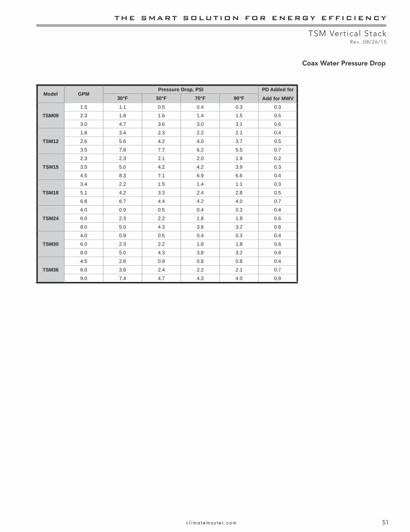
THE SMART SOLUTION FOR ENERGY EFFICIENCY
TSM Vertical StackR e v. : 0 8 / 2 6 / 1 5
51c l i m a t e m a s t e r . c o m
Coax Water Pressure Drop
Model GPMPressure Drop, PSI PD Added for
Add for MWV30°F 50°F 70°F 90°F
TSM091.5 1.1 0.5 0.4 0.3 0.3
2.3 1.8 1.6 1.4 1.5 0.5
3.0 4.7 3.6 3.0 3.1 0.6
TSM121.8 3.4 2.3 2.2 2.1 0.4
2.6 5.6 4.2 4.0 3.7 0.5
3.5 7.8 7.7 6.2 5.5 0.7
TSM152.3 2.3 2.1 2.0 1.9 0.2
3.5 5.0 4.2 4.2 3.9 0.3
4.5 8.3 7.1 6.9 6.6 0.4
TSM183.4 2.2 1.5 1.4 1.1 0.3
5.1 4.2 3.3 2.4 2.8 0.5
6.8 6.7 4.4 4.2 4.0 0.7
TSM244.0 0.9 0.5 0.4 0.3 0.4
6.0 2.3 2.2 1.8 1.8 0.6
8.0 5.0 4.3 3.8 3.2 0.8
TSM304.0 0.9 0.5 0.4 0.3 0.4
6.0 2.3 2.2 1.8 1.8 0.6
8.0 5.0 4.3 3.8 3.2 0.8
TSM364.5 2.8 0.9 0.8 0.8 0.4
6.0 3.8 2.4 2.2 2.1 0.7
9.0 7.4 4.7 4.3 4.0 0.9

CLIMATEMASTER WATER-SOURCE HEAT PUMPS
TSM Vertical StackR e v. : 0 8 / 2 6 / 1 5
52 C l i m a t e M a s t e r Wa t e r - S o u r c e H e a t P u m p s
Start-Up Log Sheet
Installer: Complete unit and system checkout and follow unit start-up procedures in the IOM. Use this form to record unit information, temperatures and pressures during start-up. Keep this form for future reference.
Job Name: ________________________________ Street Address: ___________________________________Chassis Model Number: _____________________ Serial Number: ____________________________________Cabinet Model Number: _____________________ Serial Number: ____________________________________Unit Location in Building: ______________________________________________________________________Date: ______________________________________Sales Order No: ___________________________________
In order to minimize troubleshooting and costly system failures, complete the following checks and data entries before the system is put into full operation.
PCS Motor: (Circle) HI TAP, MED TAP, LOW TAP ECM Motor CFM Setting: Cooling - (Circle) Default, Min, Max, or ______Temperatures: (Circle) F or C Heating - (Circle) Default, Min, Max, or ______
Pressures: (Circle) PSIG or kPa Antifreeze: __________Type: __________%
Cooling Mode Heating ModeTemperaturesReturn-Air DBSupply-Air DBAir Temperature DifferentialEntering FluidLeaving FluidFluid Temperature Differential
Units with DXM2 *LT1LT2Discharge LineLeaving Air
VoltagesSupply at UnitTransformer Low Side
AmpsCompressor
Allow unit to run 15 minutes in each mode before taking data.Do not connect refrigerant gauges during start up unless instructed by ClimateMaster service tech.*Temperatures can be read with service tool or communicating thermostat.

THE SMART SOLUTION FOR ENERGY EFFICIENCY
TSM Vertical StackR e v. : 0 8 / 2 6 / 1 5
53c l i m a t e m a s t e r . c o m
Preventive Maintenance
Water Coil Maintenance(Direct ground water applications only)If the system is installed in an area with a known high mineral content (125 P.P.M. or greater) in the water, it is best to establish a periodic maintenance schedule with the owner so the coil can be checked regularly. Consult the well water applications section of this manual for a more detailed water coil material selection. Should periodic coil cleaning be necessary, use standard coil cleaning procedures, which are compatible with the heat exchanger material and copper water lines. Generally, the more water fl owing through the unit, the less chance for scaling. Therefore, 1.5 gpm per ton [2.0 l/m per kW] is recommended as a minimum fl ow. Minimum fl ow rate for entering water temperatures below 50°F [10°C] is 2.0 gpm per ton [2.6 l/m per kW].
Water Coil Maintenance(All other water loop applications) Generally water coil maintenance is not needed for closed loop systems. However, if the piping is known to have high dirt or debris content, it is best to establish a periodic maintenance schedule with the owner so the water coil can be checked regularly. Dirty installations are typically the result of deterioration of iron or galvanized piping or components in the system. Open cooling towers requiring heavy chemical treatment and mineral buildup through water use can also contribute to higher maintenance. Should periodic coil cleaning be necessary, use standard coil cleaning procedures, which are compatible with both the heat exchanger material and copper water lines. Generally, the more water fl owing through the unit, the less chance for scaling. However, fl ow rates over 3 gpm per ton (3.9 l/m per kW) can produce water (or debris) velocities that can erode the heat exchanger wall and ultimately produce leaks.
Filters - Filters must be clean to obtain maximum performance. Filters should be inspected every month under normal operating conditions and be replaced when necessary. Units should never be operated without a fi lter.
Washable, high effi ciency, electrostatic fi lters, when dirty, can exhibit a very high pressure drop for the fan motor and reduce air fl ow, resulting in poor performance. It is especially important to provide consistent washing of these fi lters (in the opposite direction of the normal air fl ow) once per month using a high pressure wash similar to those found at self-serve car washes.
Condensate Drain - In areas where airborne bacteria may produce a “slimy” substance in the drain pan, it may
be necessary to treat the drain pan chemically with an algaecide approximately every three months to minimize the problem. The condensate pan may also need to be cleaned periodically to ensure indoor air quality. The condensate drain can pick up lint and dirt, especially with dirty fi lters. Inspect the drain twice a year to avoid the possibility of plugging and eventual overfl ow.
Compressor - Conduct annual amperage checks to ensure that amp draw is no more than 10% greater than indicated on the serial plate data.
Fan Motors - All units have lubricated fan motors. Fan motors should never be lubricated unless obvious, dry operation is suspected. Periodic maintenance oiling is not recommended, as it will result in dirt accumulating in the excess oil and cause eventual motor failure. Conduct annual dry operation check and amperage check to ensure amp draw is no more than 10% greater than indicated on serial plate data.
Air Coil - The air coil must be cleaned to obtain maximum performance. Check once a year under normal operating conditions and, if dirty, brush or vacuum clean. Care must be taken not to damage the aluminum fi ns while cleaning. CAUTION: Fin edges are sharp.
Cabinet - Check inside cabinet once a year. Gently brush or vacuum clean if needed. Do not tear insulation, repair with foil tape.
Refrigerant System - To maintain sealed circuit integrity, do not install service gauges unless unit operation appears abnormal. Reference the operating charts for pressures and temperatures. Verify that air and water fl ow rates are at proper levels before servicing the refrigerant circuit.
All product families have transitioned to CoreMax® high fl ow service valves. In place of Schrader ports.
The CoreMax® system:• Permits up to six times higher fl ow rate to substantially
reduce refrigerant recovery and evacuation time• Maintains compatibility with ¼” fl are standard
refrigeration hose connections• Has lower leak rates than the traditional refrigerant
valve/access fi ttings• Requires a special tool (FasTest - SCFT20A) to replace
the valve core without reclaiming, evacuating and recharging the system. The tool can be purchased directly from FasTest or check with your local supply house.
For additional information, please contact our technical service department.
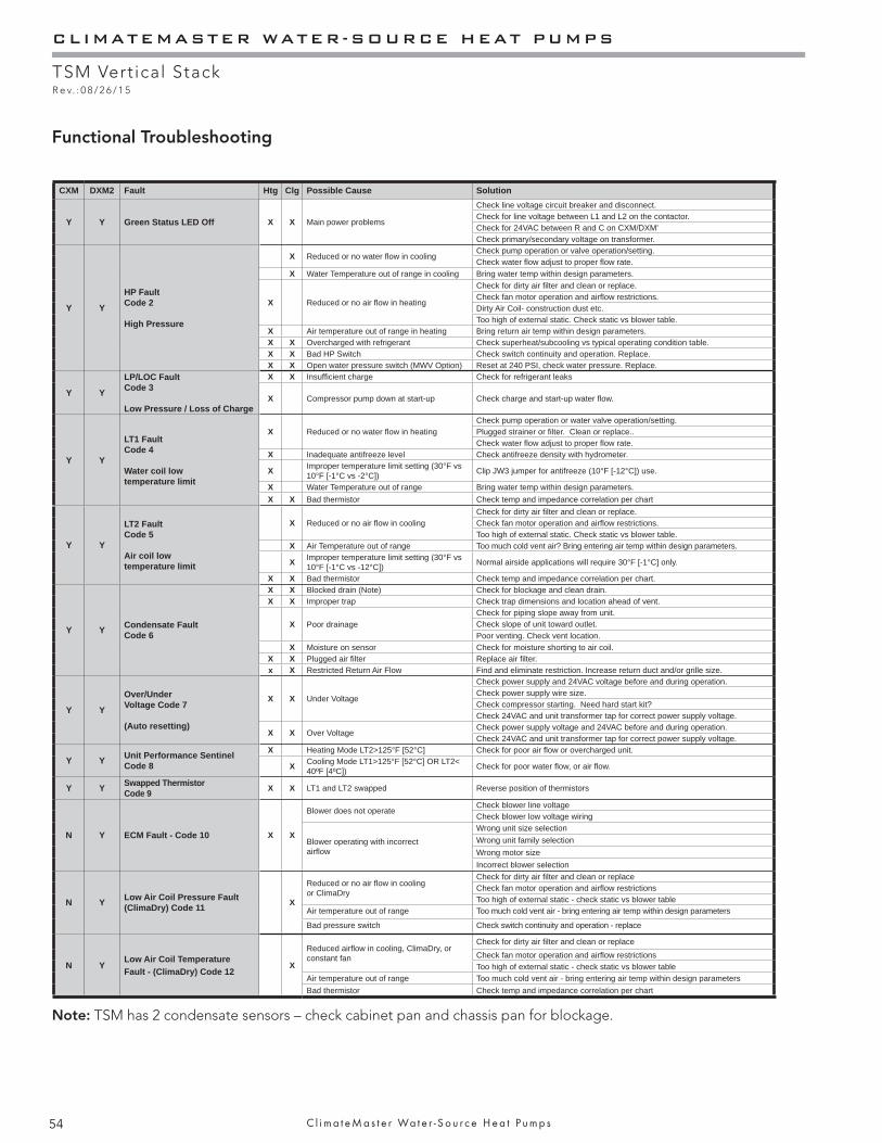
CLIMATEMASTER WATER-SOURCE HEAT PUMPS
TSM Vertical StackR e v. : 0 8 / 2 6 / 1 5
54 C l i m a t e M a s t e r Wa t e r - S o u r c e H e a t P u m p s
Functional Troubleshooting
CXM DXM2 Fault Htg Clg Possible Cause Solution
Y Y Green Status LED Off X X Main power problems
Check line voltage circuit breaker and disconnect.Check for line voltage between L1 and L2 on the contactor.Check for 24VAC between R and C on CXM/DXM'Check primary/secondary voltage on transformer.
Y Y
HP Fault Code 2
High Pressure
X Reduced or no water fl ow in coolingCheck pump operation or valve operation/setting.Check water fl ow adjust to proper fl ow rate.
X Water Temperature out of range in cooling Bring water temp within design parameters.
X Reduced or no air fl ow in heating
Check for dirty air fi lter and clean or replace.Check fan motor operation and airfl ow restrictions.Dirty Air Coil- construction dust etc.Too high of external static. Check static vs blower table.
X Air temperature out of range in heating Bring return air temp within design parameters.X X Overcharged with refrigerant Check superheat/subcooling vs typical operating condition table.X X Bad HP Switch Check switch continuity and operation. Replace.X X Open water pressure switch (MWV Option) Reset at 240 PSI, check water pressure. Replace.
Y Y
LP/LOC FaultCode 3
Low Pressure / Loss of Charge
X X Insuffi cient charge Check for refrigerant leaks
X Compressor pump down at start-up Check charge and start-up water fl ow.
Y Y
LT1 FaultCode 4
Water coil low temperature limit
X Reduced or no water fl ow in heatingCheck pump operation or water valve operation/setting.Plugged strainer or fi lter. Clean or replace..Check water fl ow adjust to proper fl ow rate.
X Inadequate antifreeze level Check antifreeze density with hydrometer.
X Improper temperature limit setting (30°F vs 10°F [-1°C vs -2°C]) Clip JW3 jumper for antifreeze (10°F [-12°C]) use.
X Water Temperature out of range Bring water temp within design parameters.X X Bad thermistor Check temp and impedance correlation per chart
Y Y
LT2 FaultCode 5
Air coil low temperature limit
X Reduced or no air fl ow in cooling Check for dirty air fi lter and clean or replace.Check fan motor operation and airfl ow restrictions.Too high of external static. Check static vs blower table.
X Air Temperature out of range Too much cold vent air? Bring entering air temp within design parameters.
X Improper temperature limit setting (30°F vs 10°F [-1°C vs -12°C]) Normal airside applications will require 30°F [-1°C] only.
X X Bad thermistor Check temp and impedance correlation per chart.
Y Y Condensate Fault Code 6
X X Blocked drain (Note) Check for blockage and clean drain.X X Improper trap Check trap dimensions and location ahead of vent.
X Poor drainageCheck for piping slope away from unit.Check slope of unit toward outlet.Poor venting. Check vent location.
X Moisture on sensor Check for moisture shorting to air coil.X X Plugged air fi lter Replace air fi lter.x X Restricted Return Air Flow Find and eliminate restriction. Increase return duct and/or grille size.
Y Y
Over/Under Voltage Code 7
(Auto resetting)
X X Under Voltage
Check power supply and 24VAC voltage before and during operation.Check power supply wire size.Check compressor starting. Need hard start kit?Check 24VAC and unit transformer tap for correct power supply voltage.
X X Over VoltageCheck power supply voltage and 24VAC before and during operation.Check 24VAC and unit transformer tap for correct power supply voltage.
Y Y Unit Performance SentinelCode 8
X Heating Mode LT2>125°F [52°C] Check for poor air fl ow or overcharged unit.
X Cooling Mode LT1>125°F [52°C] OR LT2< 40ºF [4ºC]) Check for poor water fl ow, or air fl ow.
Y Y Swapped ThermistorCode 9 X X LT1 and LT2 swapped Reverse position of thermistors
N Y ECM Fault - Code 10 X X
Blower does not operateCheck blower line voltageCheck blower low voltage wiring
Blower operating with incorrectairfl ow
Wrong unit size selectionWrong unit family selectionWrong motor sizeIncorrect blower selection
N Y Low Air Coil Pressure Fault(ClimaDry) Code 11 X
Reduced or no air fl ow in coolingor ClimaDry
Check for dirty air fi lter and clean or replaceCheck fan motor operation and airfl ow restrictionsToo high of external static - check static vs blower table
Air temperature out of range Too much cold vent air - bring entering air temp within design parameters
Bad pressure switch Check switch continuity and operation - replace
N YLow Air Coil TemperatureFault - (ClimaDry) Code 12
X
Reduced airfl ow in cooling, ClimaDry, or constant fan
Check for dirty air fi lter and clean or replaceCheck fan motor operation and airfl ow restrictionsToo high of external static - check static vs blower table
Air temperature out of range Too much cold vent air - bring entering air temp within design parametersBad thermistor Check temp and impedance correlation per chart
Note: TSM has 2 condensate sensors – check cabinet pan and chassis pan for blockage.
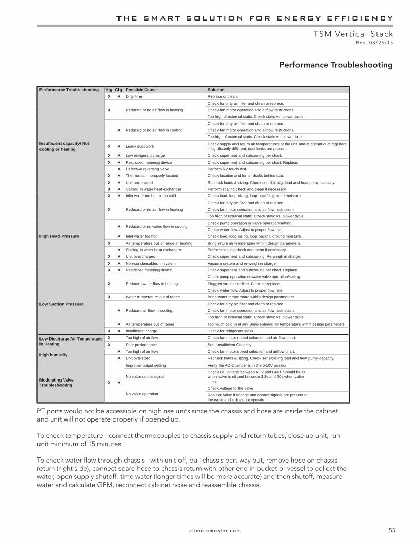
THE SMART SOLUTION FOR ENERGY EFFICIENCY
TSM Vertical StackR e v. : 0 8 / 2 6 / 1 5
55c l i m a t e m a s t e r . c o m
Performance Troubleshooting
Performance Troubleshooting Htg Clg Possible Cause Solution
Insuffi cient capacity/ Not cooling or heating
X X Dirty fi lter Replace or clean.
X Reduced or no air fl ow in heating
Check for dirty air fi lter and clean or replace.
Check fan motor operation and airfl ow restrictions.
Too high of external static. Check static vs. blower table.
X Reduced or no air fl ow in cooling
Check for dirty air fi lter and clean or replace.
Check fan motor operation and airfl ow restrictions.
Too high of external static. Check static vs. blower table.
X X Leaky duct work Check supply and return air temperatures at the unit and at distant duct registers if signifi cantly different, duct leaks are present.
X X Low refrigerant charge Check superheat and subcooling per chart.
X X Restricted metering device Check superheat and subcooling per chart. Replace.
X Defective reversing valve Perform RV touch test.
X X Thermostat improperly located Check location and for air drafts behind stat.
X X Unit undersized Recheck loads & sizing. Check sensible clg. load and heat pump capacity.
X X Scaling in water heat exchanger Perform scaling check and clean if necessary.
X X Inlet water too hot or too cold Check load, loop sizing, loop backfi ll, ground moisture.
High Head Pressure
X Reduced or no air fl ow in heating
Check for dirty air fi lter and clean or replace.
Check fan motor operation and air fl ow restrictions.
Too high of external static. Check static vs. blower table.
X Reduced or no water fl ow in coolingCheck pump operation or valve operation/setting.
Check water fl ow. Adjust to proper fl ow rate.
X Inlet water too hot Check load, loop sizing, loop backfi ll, ground moisture.
X Air temperature out of range in heating Bring return air temperature within design parameters.
X Scaling in water heat exchanger Perform scaling check and clean if necessary.
X X Unit overcharged Check superheat and subcooling. Re-weigh in charge.
X X Non-condensables in system Vacuum system and re-weigh in charge.
X X Restricted metering device. Check superheat and subcooling per chart. Replace.
Low Suction Pressure
X Reduced water fl ow in heating.
Check pump operation or water valve operation/setting.
Plugged strainer or fi lter. Clean or replace.
Check water fl ow. Adjust to proper fl ow rate.
X Water temperature out of range. Bring water temperature within design parameters.
X Reduced air fl ow in cooling.
Check for dirty air fi lter and clean or replace.
Check fan motor operation and air fl ow restrictions.
Too high of external static. Check static vs. blower table.
X Air temperature out of range Too much cold vent air? Bring entering air temperature within design parameters.
X X Insuffi cient charge Check for refrigerant leaks.
Low Discharge Air Temperature in Heating
X Too high of air fl ow Check fan motor speed selection and air fl ow chart.
X Poor performance See ‘Insuffi cient Capacity’
High humidityX Too high of air fl ow Check fan motor speed selection and airfl ow chart.
X Unit oversized Recheck loads & sizing. Check sensible clg load and heat pump capacity.
Modulating Valve Troubleshooting X X
Improper output setting Verify the AO-2 jumper is in the 0-10V position
No valve output signalCheck DC voltage between AO2 and GND. Should be Owhen valve is off and between 3.3v and 10v when valveis on.
No valve operationCheck voltage to the valve
Replace valve if voltage and control signals are present at the valve and it does not operate
PT ports would not be accessible on high rise units since the chassis and hose are inside the cabinet and unit will not operate properly if opened up.
To check temperature - connect thermocouples to chassis supply and return tubes, close up unit, run unit minimum of 15 minutes.
To check water fl ow through chassis - with unit off, pull chassis part way out, remove hose on chassis return (right side), connect spare hose to chassis return with other end in bucket or vessel to collect the water, open supply shutoff, time water (longer times will be more accurate) and then shutoff, measure water and calculate GPM, reconnect cabinet hose and reassemble chassis.
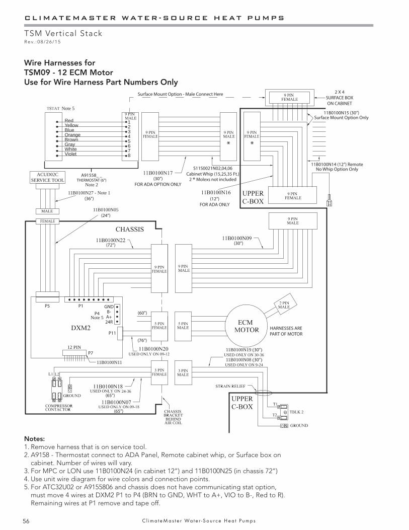
CLIMATEMASTER WATER-SOURCE HEAT PUMPS
TSM Vertical StackR e v. : 0 8 / 2 6 / 1 5
56 C l i m a t e M a s t e r Wa t e r - S o u r c e H e a t P u m p s
Wire Harnesses forTSM09 - 12 ECM MotorUse for Wire Harness Part Numbers Only
A91558_ _THERMOSTAT (6”)
Note 2
(65”)24-36
BEHIND AIR COIL
(65”)
(60”)
(76”)
(30”)(72”)
(30”) FOR ADA OPTION ONLY
Surface Mount Option - Male Connect Here
S11S0021N02,04,06Cabinet Whip (15,25,35 Ft.)
2 * Molexs not included
11B0100N15 (30”)Surface Mount Option Only
11B0100N14 (12”) RemoteNo Whip Option Only
P1
P4Note 5
GNDB-A+24R
P5
P7
MALE 11B0100N05(24”)
ACUD02CSERVICE TOOL
11B0100N27 - Note 1(36”)
P11
2 X 4 SURFACE BOX ON CABINET
HARNESSES ARE PART OF MOTOR
11B0100N19 (30”) USED ONLY ON 30-3611B0100N08 (30”) USED ONLY ON 9-24
* *
Note 5
RedYellowBlueOrangeBrown GrayWhiteViolet
12345678
12 PIN
11B0100N11
(12”) FOR ADA ONLY
Notes:1. Remove harness that is on service tool.2. A9158 - Thermostat connect to ADA Panel, Remote cabinet whip, or Surface box on
cabinet. Number of wires will vary.3. For MPC or LON use 11B0100N24 (in cabinet 12”) and 11B0100N25 (in chassis 72”)4. Use unit wire diagram for wire colors and connection points.5. For ATC32U02 or A9155806 and chassis does not have communicating stat option,
must move 4 wires at DXM2 P1 to P4 (BRN to GND, WHT to A+, VIO to B-, Red to R). Remaining wires at P1 remove and tape off.

THE SMART SOLUTION FOR ENERGY EFFICIENCY
TSM Vertical StackR e v. : 0 8 / 2 6 / 1 5
57c l i m a t e m a s t e r . c o m
Wire Harnesses forTSM15 - 36 ECM Motor
Use for Wire Harness Part Numbers Only
A91558_ _THERMOSTAT (6”)
Note 2(30”)
FOR ADA OPTION ONLY
(30”)
(36”) (36”)
(72”)
(65”)
P8
(65”)
(65”)
P5
MALE
ACUD02CSERVICE TOOL
11B0100N05(24”)
11B0100N27 - Note 1(36”)
24-36
11B0100N19 (30”) USED ONLY ON 30-36
11B0100N12 (12”) USED ONLY ON 15-36
11B0100N08 (30”) USED ONLY ON 9-24
5 PINFEMALE
Surface Mount Option - Male Connect Here
BEHIND AIR COIL
* *
P1P4
Note 5
GNDB-A+24R
Note 5
P712 PIN
11B0100N11
RedYellowBlueOrangeBrown GrayWhiteViolet
12345678
11B0100N15 (30”)Surface Mount Option Only
11B0100N14 (12”) RemoteNo Whip Option Only
2 X 4 SURFACE BOX ON CABINET
(12”) FOR ADA ONLY
S11S0021N02,04,06Cabinet Whip (15,25,35 Ft.)
2 * Molexs not included
Notes:1. Remove harness that is on service tool.2. A9158 - Thermostat connect to ADA Panel, Remote cabinet whip, or Surface box on
cabinet. Number of wires will vary.3. For MPC or LON use 11B0100N24 (in cabinet 12”) and 11B0100N25 (in chassis 72”)4. Use unit wire diagram for wire colors and connection points.5. For ATC32U02 or A9155806 and chassis does not have communicating stat option,
must move 4 wires at DXM2 P1 to P4 (BRN to GND, WHT to A+, VIO to B-, Red to R). Remaining wires at P1 remove and tape off.
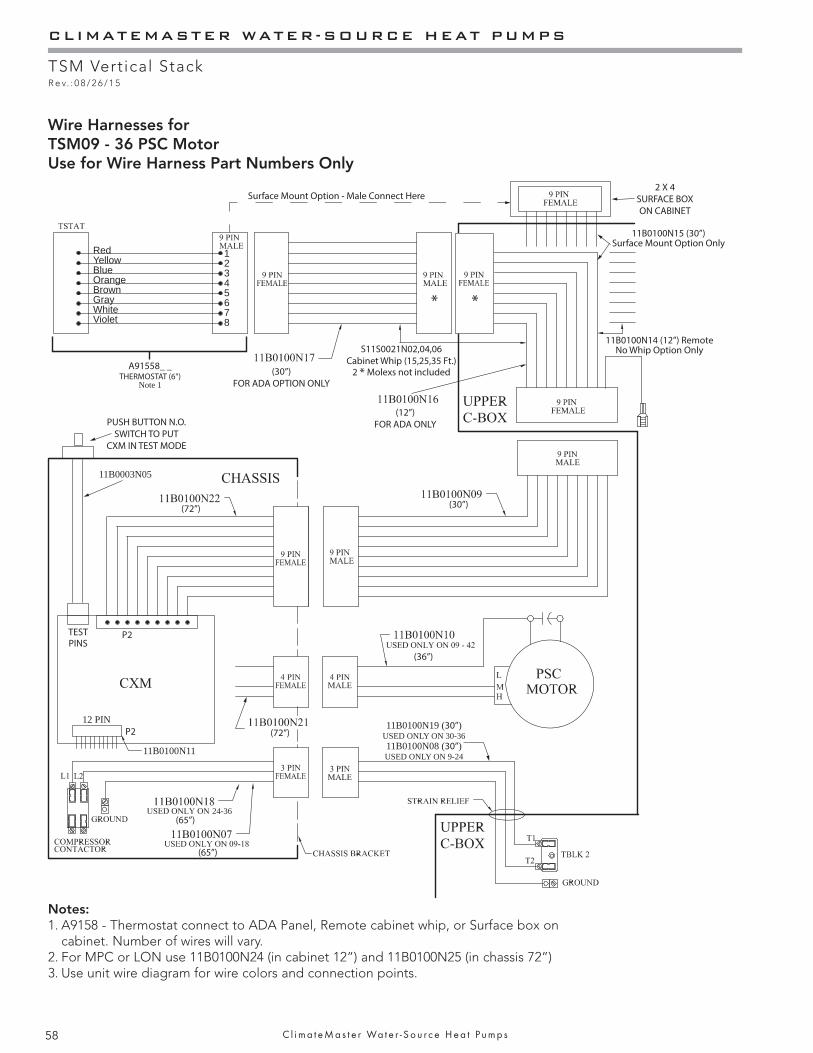
CLIMATEMASTER WATER-SOURCE HEAT PUMPS
TSM Vertical StackR e v. : 0 8 / 2 6 / 1 5
58 C l i m a t e M a s t e r Wa t e r - S o u r c e H e a t P u m p s
Wire Harnesses forTSM09 - 36 PSC MotorUse for Wire Harness Part Numbers Only
A91558_ _THERMOSTAT (6”)
Note 1
(30”) FOR ADA OPTION ONLY
P2TESTPINS
(72”) (30”)
(72”)
(65”)
(65”)
(36”)
24-36
11B0100N19 (30”) USED ONLY ON 30-3611B0100N08 (30”) USED ONLY ON 9-24
PUSH BUTTON N.O.SWITCH TO PUT
CXM IN TEST MODE
11B0003N05
Surface Mount Option - Male Connect Here
* *
RedYellowBlueOrangeBrown GrayWhiteViolet
12345678
P212 PIN
11B0100N11
S11S0021N02,04,06Cabinet Whip (15,25,35 Ft.)
2 * Molexs not included
(12”) FOR ADA ONLY
11B0100N15 (30”)Surface Mount Option Only
11B0100N14 (12”) RemoteNo Whip Option Only
2 X 4 SURFACE BOX ON CABINET
Notes:1. A9158 - Thermostat connect to ADA Panel, Remote cabinet whip, or Surface box on
cabinet. Number of wires will vary.2. For MPC or LON use 11B0100N24 (in cabinet 12”) and 11B0100N25 (in chassis 72”)3. Use unit wire diagram for wire colors and connection points.
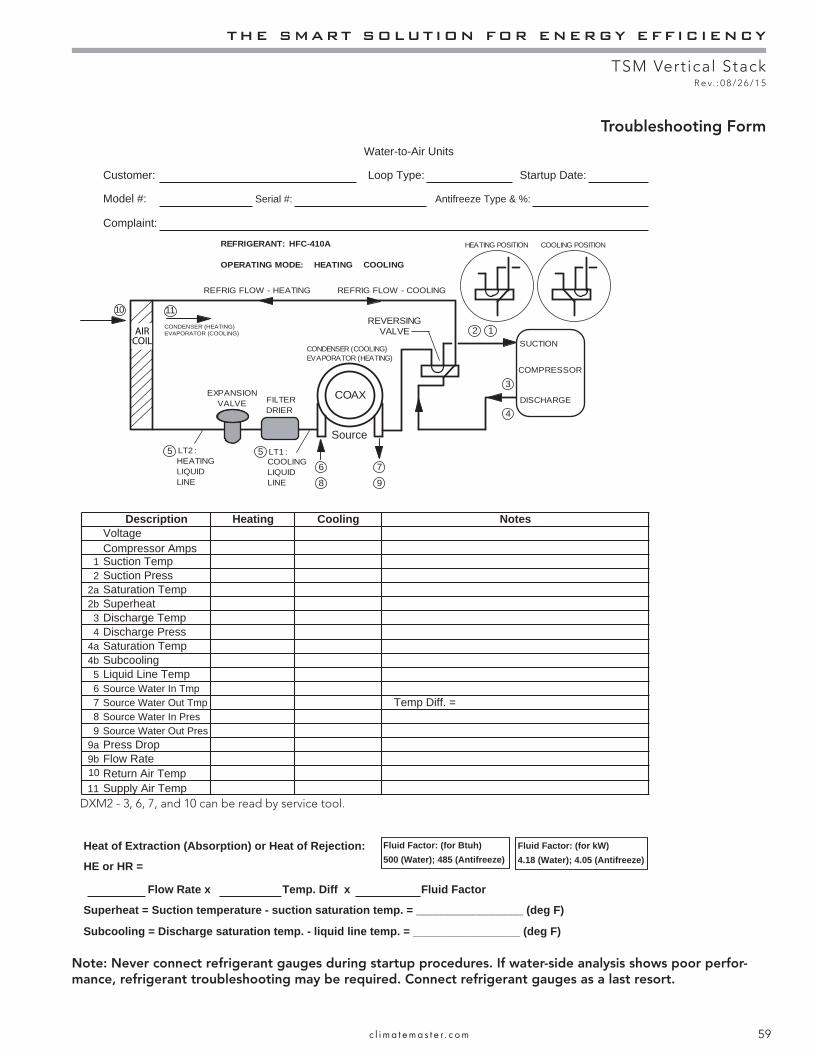
THE SMART SOLUTION FOR ENERGY EFFICIENCY
TSM Vertical StackR e v. : 0 8 / 2 6 / 1 5
59c l i m a t e m a s t e r . c o m
Troubleshooting Form
Note: Never connect refrigerant gauges during startup procedures. If water-side analysis shows poor perfor-mance, refrigerant troubleshooting may be required. Connect refrigerant gauges as a last resort.
:etaD putratS:epyT pooL:remotsuC
Model #: :% & epyT ezeerfitnA:# laireS
Complaint:
VoltageCompressor Amps
1 Suction Temp2 Suction Press
2a Saturation Temp2b Superheat3 Discharge Temp4 Discharge Press
4a Saturation Temp4b Subcooling5 Liquid Line Temp6 Source Water In Tmp7 Source Water Out Tmp8 Source Water In Pres9
1011
Source Water Out Pres9a Press Drop9b Flow Rate
Return Air TempSupply Air Temp
Heat of Extraction (Absorption) or Heat of Rejection:
HE or HR =
Flow Rate x Temp. Diff x Fluid Factor
setoNnoitpircseD
Temp Diff. =
Heating Cooling
Water-to-Air Units
COMPRESSOR
DISCHARGE
SUCTION
EXPANSIONVALVE FILTER
DRIER
REVERSINGVALVE
HEATING POSITION COOLING POSITION
1
COAX
5
10 11
9
7
8
6
4
3
2
LT2 : LT1 :HEATINGLIQUIDLINE
5COOLINGLIQUIDLINE
CONDENSER (COOLING)EVAPORATOR (HEATING)
REFRIG FLOW - HEATING REFRIG FLOW - COOLING
REFRIGERANT: HFC-410A
OPERATING MODE: HEATING COOLING
Fluid Factor: (for Btuh)500 (Water); 485 (Antifreeze)
Source
Fluid Factor: (for kW)4.18 (Water); 4.05 (Antifreeze)
AIRCOIL
Superheat = Suction temperature - suction saturation temp. = _________________ (deg F)
Subcooling = Discharge saturation temp. - liquid line temp. = _________________ (deg F)
CONDENSER (HEATING)EVAPORATOR (COOLING)
DXM2 - 3, 6, 7, and 10 can be read by service tool.
CLIMATEMASTER WATER-SOURCE HEAT PUMPS
TSM Vertical StackR e v. : 0 8 / 2 6 / 1 5
60 C l i m a t e M a s t e r Wa t e r - S o u r c e H e a t P u m p s
WarrantyC
LIM
AT
E M
AST
ER
, IN
C.
LIM
ITE
D E
XP
RE
SS W
AR
RA
NT
Y/ L
IMIT
AT
ION
OF
RE
ME
DIE
S A
ND
LIA
BIL
ITY
It is
exp
ress
ly u
nder
stoo
d th
at u
nles
s a
stat
emen
t is
spec
i ca
lly id
enti
ed
as a
war
rant
y, s
tate
men
ts m
ade
by C
limat
e M
aste
r, In
c., a
Del
awar
e co
rpor
atio
n, (
“CM
”) o
r its
rep
rese
ntat
ives
, rel
atin
g to
CM
’s p
rodu
cts,
whe
ther
ora
l, w
ritte
n or
con
tain
ed in
any
sal
es li
tera
ture
, cat
alog
or
any
othe
r ag
reem
ent,
are
not e
xpre
ss w
arra
ntie
s an
d do
not
for
m a
par
t of
the
basi
s of
the
barg
ain,
but
are
mer
ely
CM
’s o
pini
on o
r co
mm
enda
tion
of C
M’s
pro
duct
s.
EX
CE
PT
AS
SPE
CIF
ICA
LLY
SE
T F
OR
TH
HE
RE
IN, T
HE
RE
IS
NO
EX
PR
ESS
WA
RR
AN
TY
AS
TO
AN
Y O
F C
M’S
PR
OD
UC
TS.
CM
MA
KE
S N
O W
AR
RA
NT
Y A
GA
INST
LA
TE
NT
DE
FE
CT
S. C
M M
AK
ES
NO
WA
RR
AN
TY
OF
ME
RC
HA
NT
AB
ILIT
Y O
F T
HE
GO
OD
S O
R O
F T
HE
FIT
NE
SS O
F T
HE
GO
OD
S F
OR
AN
Y P
AR
TIC
UL
AR
PU
RP
OSE
.
GR
AN
T O
F L
IMIT
ED
EX
PR
ESS
WA
RR
AN
TY
CM
war
rant
s C
M p
rodu
cts
purc
hase
d an
d re
tain
ed in
the
Uni
ted
Stat
es o
f Am
eric
a an
d C
anad
a to
be
free
fro
m d
efec
ts in
mat
eria
l and
wor
kman
ship
und
er n
orm
al u
se a
nd m
aint
enan
ce a
s fo
llow
s: (
1) A
ll co
mpl
ete
air
cond
ition
-in
g, h
eatin
g an
d/or
hea
t pum
p un
its b
uilt
or s
old
by C
M f
or tw
elve
(12
) m
onth
s fr
om d
ate
of u
nit s
tart
up
or e
ight
een
(18)
mon
ths
from
dat
e of
shi
pmen
t (fr
om f
acto
ry),
whi
chev
er c
omes
rs
t; (2
) R
epai
r an
d re
plac
emen
t par
ts,
whi
ch a
re n
ot s
uppl
ied
unde
r w
arra
nty,
for
nin
tey
(90)
day
s fr
om d
ate
of s
hipm
ent (
from
fac
tory
). A
ll pa
rts
mus
t be
retu
rned
to C
M’s
fac
tory
in O
klah
oma
City
, Okl
ahom
a, f
reig
ht p
repa
id, n
o la
ter
than
six
ty (
60)
days
aft
er
the
date
of
the
failu
re o
f th
e pa
rt; i
f C
M d
eter
min
es th
e pa
rt to
be
defe
ctiv
e an
d w
ithin
CM
’s L
imite
d E
xpre
ss W
arra
nty,
CM
sha
ll, w
hen
such
par
t has
bee
n ei
ther
rep
lace
d or
rep
aire
d, r
etur
n su
ch to
a f
acto
ry r
ecog
nize
d de
aler
, co
ntra
ctor
or
serv
ice
orga
niza
tion,
F.O
.B. C
M’s
fac
tory
, Okl
ahom
a C
ity, O
klah
oma,
fre
ight
pre
paid
. The
war
rant
y on
any
par
ts r
epai
red
or r
epla
ced
unde
r w
arra
nty
expi
res
at th
e en
d of
the
orig
inal
war
rant
y pe
riod
.
Thi
s w
arra
nty
does
not
cov
er a
nd d
oes
not a
pply
to: (
1) A
ir
lters
, fus
es, r
efri
gera
nt,
uid
s, o
il; (
2) P
rodu
cts
relo
cate
d af
ter
initi
al in
stal
latio
n; (
3) A
ny p
ortio
n or
com
pone
nt o
f an
y sy
stem
that
is n
ot s
uppl
ied
by C
M, r
egar
dles
s of
the
caus
e of
the
failu
re o
f su
ch p
ortio
n or
com
pone
nt; (
4) P
rodu
cts
on w
hich
the
unit
iden
ti c
atio
n ta
gs o
r la
bels
hav
e be
en r
emov
ed o
r de
face
d; (
5) P
rodu
cts
on w
hich
pay
men
t to
CM
is o
r ha
s be
en in
def
ault;
(6)
Pro
duct
s w
hich
hav
e de
fect
s or
dam
age
whi
ch r
esul
t fro
m im
prop
er in
stal
latio
n, w
irin
g, e
lect
rica
l im
bala
nce
char
acte
rist
ics
or m
aint
enan
ce; o
r ar
e ca
used
by
acci
dent
, mis
use
or a
buse
, r
e,
ood,
alte
ratio
n or
mis
appl
icat
ion
of th
e pr
od-
uct;
(7)
Prod
ucts
whi
ch h
ave
defe
cts
or d
amag
e w
hich
res
ult f
rom
a c
onta
min
ated
or
corr
osiv
e ai
r or
liqu
id s
uppl
y, o
pera
tion
at a
bnor
mal
tem
pera
ture
s, o
r un
auth
oriz
ed o
peni
ng o
f re
frig
eran
t cir
cuit;
(8)
Mol
d, f
ungu
s or
bac
teri
a da
mag
es; (
9) P
rodu
cts
subj
ecte
d to
cor
rosi
on o
r ab
rasi
on; (
10)
Prod
ucts
man
ufac
ture
d or
sup
plie
d by
oth
ers;
(11
) Pr
oduc
ts w
hich
hav
e be
en s
ubje
cted
to m
isus
e, n
eglig
ence
or
acci
dent
s; (
12)
Prod
ucts
whi
ch h
ave
been
ope
rate
d in
a m
anne
r co
ntra
ry to
CM
’s p
rint
ed in
stru
ctio
ns; o
r (1
3) P
rodu
cts
whi
ch h
ave
defe
cts,
dam
age
or in
suf
cie
nt p
erfo
rman
ce a
s a
resu
lt of
insu
f c
ient
or
inco
rrec
t sys
tem
des
ign
or th
e im
prop
er a
pplic
atio
n of
CM
’s p
rodu
cts.
CM
is n
ot r
espo
nsib
le f
or: (
1) T
he c
osts
of
any
uid
s, r
efri
gera
nt o
r ot
her
syst
em c
ompo
nent
s, o
r as
soci
ated
labo
r to
rep
air
or r
epla
ce th
e sa
me,
whi
ch is
incu
rred
as
a re
sult
of a
def
ectiv
e pa
rt c
over
ed b
y C
M’s
Lim
ited
Exp
ress
W
arra
nty;
(2)
The
cos
ts o
f la
bor,
refr
iger
ant,
mat
eria
ls o
r se
rvic
e in
curr
ed in
rem
oval
of
the
defe
ctiv
e pa
rt, o
r in
obt
aini
ng a
nd r
epla
cing
the
new
or
repa
ired
par
t; or
, (3)
Tra
nspo
rtat
ion
cost
s of
the
defe
ctiv
e pa
rt f
rom
the
inst
alla
-tio
n si
te to
CM
or
of th
e re
turn
of
any
part
not
cov
ered
by
CM
’s L
imite
d E
xpre
ss W
arra
nty.
Lim
itat
ion:
Thi
s L
imite
d E
xpre
ss W
arra
nty
is g
iven
in li
eu o
f al
l oth
er w
arra
ntie
s. I
f, n
otw
ithst
andi
ng th
e di
scla
imer
s co
ntai
ned
here
in, i
t is
dete
rmin
ed th
at o
ther
war
rant
ies
exis
t, an
y su
ch w
arra
ntie
s, in
clud
ing
with
out l
imita
-tio
n an
y ex
pres
s w
arra
ntie
s or
any
impl
ied
war
rant
ies
of
tnes
s fo
r pa
rtic
ular
pur
pose
and
mer
chan
tabi
lity,
sha
ll be
lim
ited
to th
e du
ratio
n of
the
Lim
ited
Exp
ress
War
rant
y.
LIM
ITA
TIO
N O
F R
EM
ED
IES
In th
e ev
ent o
f a
brea
ch o
f th
e L
imite
d E
xpre
ss W
arra
nty,
CM
will
onl
y be
obl
igat
ed a
t CM
’s o
ptio
n to
rep
air
the
faile
d pa
rt o
r un
it or
to f
urni
sh a
new
or
rebu
ilt p
art o
r un
it in
exc
hang
e fo
r th
e pa
rt o
r un
it w
hich
has
fai
led.
If
afte
r w
ritte
n no
tice
to C
M’s
fac
tory
in O
klah
oma
City
, Okl
ahom
a of
eac
h de
fect
, mal
func
tion
or o
ther
fai
lure
and
a r
easo
nabl
e nu
mbe
r of
atte
mpt
s by
CM
to c
orre
ct th
e de
fect
, mal
func
tion
or o
ther
fai
lure
and
the
rem
edy
fails
of
its
esse
ntia
l pur
pose
, CM
sha
ll re
fund
the
purc
hase
pri
ce p
aid
to C
M in
exc
hang
e fo
r th
e re
turn
of
the
sold
goo
d(s)
. Sai
d re
fund
sha
ll be
the
max
imum
liab
ility
of
CM
. TH
IS R
EM
ED
Y I
S T
HE
SO
LE
AN
D E
XC
LU
SIV
E
RE
ME
DY
OF
TH
E B
UY
ER
OR
TH
EIR
PU
RC
HA
SER
AG
AIN
ST C
M F
OR
BR
EA
CH
OF
CO
NT
RA
CT
, FO
R T
HE
BR
EA
CH
OF
AN
Y W
AR
RA
NT
Y O
R F
OR
CM
’S N
EG
LIG
EN
CE
OR
IN
ST
RIC
T L
IAB
ILIT
Y.
LIM
ITA
TIO
N O
F L
IAB
ILIT
YC
M s
hall
have
no
liabi
lity
for
any
dam
ages
if C
M’s
per
form
ance
is d
elay
ed f
or a
ny r
easo
n or
is p
reve
nted
to a
ny e
xten
t by
any
even
t suc
h as
, but
not
lim
ited
to: a
ny w
ar, c
ivil
unre
st, g
over
nmen
t res
tric
tions
or
rest
rain
ts, s
trik
es
or w
ork
stop
page
s,
re,
ood
, acc
iden
t, sh
orta
ges
of tr
ansp
orta
tion,
fue
l, m
ater
ial,
or la
bor,
acts
of
God
or
any
othe
r re
ason
bey
ond
the
sole
con
trol
of
CM
. CM
EX
PR
ESS
LY D
ISC
LA
IMS
AN
D E
XC
LU
DE
S A
NY
LIA
BIL
-IT
Y F
OR
CO
NSE
QU
EN
TIA
L O
R I
NC
IDE
NT
AL
DA
MA
GE
IN
CO
NT
RA
CT
, FO
R B
RE
AC
H O
F A
NY
EX
PR
ESS
OR
IM
PL
IED
WA
RR
AN
TY
, OR
IN
TO
RT
, WH
ET
HE
R F
OR
CM
’s N
EG
LIG
EN
CE
OR
AS
STR
ICT
LIA
BIL
ITY
.
OB
TA
ININ
G W
AR
RA
NT
Y P
ER
FO
RM
AN
CE
Nor
mal
ly, t
he c
ontr
acto
r or
ser
vice
org
aniz
atio
n w
ho in
stal
led
the
prod
ucts
will
pro
vide
war
rant
y pe
rfor
man
ce f
or th
e ow
ner.
Shou
ld th
e in
stal
ler
be u
nava
ilabl
e, c
onta
ct a
ny C
M r
ecog
nize
d de
aler
, con
trac
tor
or s
ervi
ce o
rgan
iza-
tion.
If
assi
stan
ce is
req
uire
d in
obt
aini
ng w
arra
nty
perf
orm
ance
, wri
te o
r ca
ll:
Clim
ate
Mas
ter,
Inc.
• C
usto
mer
Ser
vice
• 7
300
S.W
. 44t
h St
reet
• O
klah
oma
City
, Okl
ahom
a 73
179
(40
5) 7
45-6
000
NO
TE
: Som
e st
ates
or
Can
adia
n pr
ovin
ces
do n
ot a
llow
lim
itatio
ns o
n ho
w lo
ng a
n im
plie
d w
arra
nty
last
s, o
r th
e lim
itatio
n or
exc
lusi
ons
of c
onse
quen
tial o
r in
cide
ntal
dam
ages
, so
the
fore
goin
g ex
clus
ions
and
lim
itatio
ns m
ay
not a
pply
to y
ou. T
his
war
rant
y gi
ves
you
spec
i c
lega
l rig
hts,
and
you
may
als
o ha
ve o
ther
rig
hts
whi
ch v
ary
from
sta
te to
sta
te a
nd f
rom
Can
adia
n pr
ovin
ce to
Can
adia
n pr
ovin
ce.
Plea
se r
efer
to th
e C
M I
nsta
llatio
n, O
pera
tion
and
Mai
nten
ance
Man
ual f
or o
pera
ting
and
mai
nten
ance
inst
ruct
ions
.
*LC083*
Rev
.: 1
1/09
L
C08
3

THE SMART SOLUTION FOR ENERGY EFFICIENCY
TSM Vertical StackR e v. : 0 8 / 2 6 / 1 5
61c l i m a t e m a s t e r . c o m
Notes
CLIMATEMASTER WATER-SOURCE HEAT PUMPS
TSM Vertical StackR e v. : 0 8 / 2 6 / 1 5
62 C l i m a t e M a s t e r Wa t e r - S o u r c e H e a t P u m p s
Notes

THE SMART SOLUTION FOR ENERGY EFFICIENCY
TSM Vertical StackR e v. : 0 8 / 2 6 / 1 5
63c l i m a t e m a s t e r . c o m
Notes
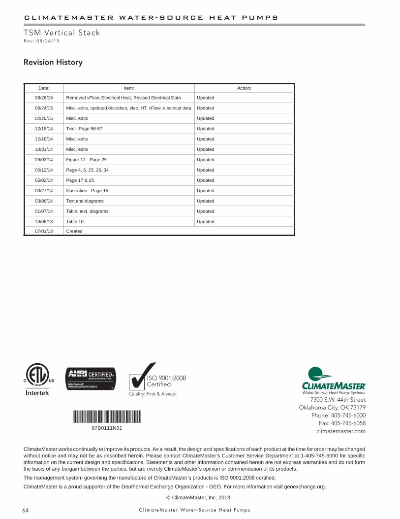
CLIMATEMASTER WATER-SOURCE HEAT PUMPS
TSM Vertical StackR e v. : 0 8 / 2 6 / 1 5
64 C l i m a t e M a s t e r Wa t e r - S o u r c e H e a t P u m p s
Date: Item: Action:
08/26/15 Removed vFlow, Electrical Heat, Revised Electrical Data Updated
06/24/15 Misc. edits, updated decoders, elec. HT, vFlow, electrical data Updated
02/25/15 Misc. edits Updated
12/18/14 Text - Page 56-57 Updated
12/16/14 Misc. edits Updated
10/31/14 Misc. edits Updated
09/03/14 Figure 12 - Page 29 Updated
05/12/14 Page 4, 6, 23, 26, 34 Updated
05/02/14 Page 17 & 25 Updated
03/27/14 Illustration - Page 15 Updated
03/06/14 Text and diagrams Updated
01/07/14 Table, text, diagrams Updated
10/08/13 Table 10 Updated
07/01/13 Created
Revision History
97B0111N01
*97B0111N01*
7300 S.W. 44th StreetOklahoma City, OK 73179
Phone: 405-745-6000Fax: 405-745-6058
climatemaster.com
ISO 9001:2008Certified
Quality: First & Always
ClimateMaster works continually to improve its products. As a result, the design and specifi cations of each product at the time for order may be changed without notice and may not be as described herein. Please contact ClimateMaster’s Customer Service Department at 1-405-745-6000 for specifi c information on the current design and specifi cations. Statements and other information contained herein are not express warranties and do not form the basis of any bargain between the parties, but are merely ClimateMaster’s opinion or commendation of its products.
The management system governing the manufacture of ClimateMaster’s products is ISO 9001:2008 certifi ed.
ClimateMaster is a proud supporter of the Geothermal Exchange Organization - GEO. For more information visit geoexchange.org. © ClimateMaster, Inc. 2013


![table Of Contents Tranquility (tr) Series - Climate Master · TT 1 2 TT = Tranquility Two Stage Scroll Model Type V 3 V = Vertical Upflow ... Air Coil Dimensions (h x w) - (in) [mm]](https://img.dokumen.tips/doc/110x75/5ae786a37f8b9a3d3b8ea547/table-of-contents-tranquility-tr-series-climate-1-2-tt-tranquility-two-stage.jpg)


![Tranquility 22 (TZ) Series - 22 Digital (TZ) Series TWO-STAGE HORIZONTAL AND VERTICAL EARTHPURE® SYSTEMS SIZES 024-060 [7.0-17.5 kW]](https://img.dokumen.tips/doc/110x75/5a9862497f8b9a9c5b8d635b/pdftranquility-22-tz-series-22-digital-tz-series-two-stage-horizontal-and.jpg)