Embed Size (px)
Citation preview

CONFIDENTIAL
TR-900 GSM/GPRS Module
Product Technical Specifications and Design Notes
Date : 18 October 2012
Document Version : 1.5
Our Reference : 02000B33

All specifications are correct at the time of release. iWOW Connections owns the proprietary rights to the information contained herein this document. It may not be edited, copied or circulated without prior written agreement by iWOW Connections Pte Ltd. © 2011, 2012 iWOW Connections Pte Ltd.
Confidential
TR-900 Module Product Technical Specifications •02000B33 v1.5
i
Document History
Revision Date Document History
1.0 20 Dec 2010 Preliminary Release
1.1 30 May 2011 Commercial Release Updated contents and electrical characteristics Updated TR-900 mechanical drawing
1.2 28 Oct 2011 Updated power consumption specification Updated design notes
1.3 27 February 2012 Updated speaker design notes
1.4 18 June 2012 Updated sleep mode details
1.5 18 Oct 2012 Update ring indicator and LED Pulse Generator

All specifications are correct at the time of release. iWOW Connections owns the proprietary rights to the information contained herein this document. It may not be edited, copied or circulated without prior written agreement by iWOW Connections Pte Ltd. © 2011, 2012 iWOW Connections Pte Ltd.
Confidential
TR-900 Module Product Technical Specifications •02000B33 v1.5
ii
GENERAL NOTE
This document aims to support the application and engineering efforts of iWOW’s customers. This document is
intended for testing, evaluation, integration, and information purposes only.
iWOW makes every effort to ensure that the quality of the information. However, the content of this
documentation is provided on an “as is” basis and may contain deficiencies or inadequacies.
iWOW disclaims any warranty and all responsibility for the application of the device(s) that is made in relation
to the accuracy, reliability or contents of this document. iWOW is not liable for any injury, loss or damage of
any kind that may incur from the use or reliance of this document.
iWOW reserves the right to make any modifications, additions and deletions to this document due to
typographical errors, inaccurate information, or improvement to our products at any time without notice.

All specifications are correct at the time of release. iWOW Connections owns the proprietary rights to the information contained herein this document. It may not be edited, copied or circulated without prior written agreement by iWOW Connections Pte Ltd. © 2011, 2012 iWOW Connections Pte Ltd.
Confidential
TR-900 Module Product Technical Specifications •02000B33 v1.5
iii
TABLE OF CONTENTS
1 INTRODUCTION .................................................................................................................................. 1
1.1 Reference Documents .............................................................................................................................. 1
1.2 Abbreviations ........................................................................................................................................... 1
1.3 Type Approvals ......................................................................................................................................... 3
1.4 Regulatory Requirement .......................................................................................................................... 4
1.4.1 Requirement for FCC Regulatory Compliance .......................................................................................... 4
1.4.2 RF Exposure Requirement ........................................................................................................................ 5
1.5 Safety Precautions .................................................................................................................................... 5
2 TECHNICAL SPECIFICATIONS ............................................................................................................... 7
2.1 General Specifications .............................................................................................................................. 7
2.2 GSM/ GPRS Specifications ........................................................................................................................ 7
2.3 RF Frequencies ......................................................................................................................................... 8
2.4 Baseband Functionalities ......................................................................................................................... 8
2.5 Interface Specifications ............................................................................................................................ 9
3 FUNCTIONAL ARCHITECTURE ........................................................................................................... 10
4 INTERFACES ...................................................................................................................................... 11
4.1 General-Purpose Connector (GPC) ......................................................................................................... 11
4.1.1 On-Board GPC Pin Assignments ............................................................................................................. 11
4.1.2 On-Board GPC Pin-Out description ........................................................................................................ 12
4.2 Power Supply and Ground – VBAT, GND ................................................................................................ 14
4.3 Operating Modes.................................................................................................................................... 15
4.3.1 Power Specs ........................................................................................................................................... 16
4.4 Backup Power Supply – VBACKUP .......................................................................................................... 17
4.4.1 Application ............................................................................................................................................. 17
4.5 Battery-Charging Interface (BCI) – PCHG, ICTL, VCCS ............................................................................. 18
4.6 Analog to Digital Converter (ADC) – ADCIN1, ADCIN2 ........................................................................... 19
4.7 Power ON Control - PWON ..................................................................................................................... 20
4.7.1 Auto Switch-ON ...................................................................................................................................... 20
4.7.2 Manual Switch ON .................................................................................................................................. 20
4.7.3 Switch-OFF Condition ............................................................................................................................. 21
4.8 Reset Signal - RESET ............................................................................................................................... 21
4.9 Digital Supply Output - VIO .................................................................................................................... 23

All specifications are correct at the time of release. iWOW Connections owns the proprietary rights to the information contained herein this document. It may not be edited, copied or circulated without prior written agreement by iWOW Connections Pte Ltd. © 2011, 2012 iWOW Connections Pte Ltd.
Confidential
TR-900 Module Product Technical Specifications •02000B33 v1.5
iv
4.10 Subscriber Identity Module (SIM) Interface - SIMIO, SIMCLK, SIMRST, VRSIM, SIMDTC ....................... 23
4.10.1 SIM Detection .................................................................................................................................... 24
4.10.2 SIM Card Holder / Embedded SIM ..................................................................................................... 25
4.11 Serial Link (UART) Interfaces .................................................................................................................. 25
4.11.1 Modem port - UART_TX, UART_RX, UART_CTS, UART_RTS, RI, DCD, DTR, DSR ............................... 25
4.12 Application ............................................................................................................................................. 26
4.12.1 Ring Indicator - RI .............................................................................................................................. 27
4.13 USB Interface – VBUS, USB_DM, USB_DP .............................................................................................. 28
4.13.1 Application ......................................................................................................................................... 28
4.14 Analog Audio Interfaces – MICIN, MICIP, EARN, EARP, SPKNA, SPKPA .................................................. 29
4.14.1 Microphone input – MICIN, MICIP .................................................................................................... 29
4.14.2 MIC Application ................................................................................................................................. 29
4.14.2.1 Differential Ended ............................................................................................................... 29
4.14.2.2 Single-end ............................................................................................................................ 30
4.14.3 Earphone – EARN, ERNP .................................................................................................................... 30
4.14.4 Speaker – SPKNA, SPKPA ................................................................................................................... 31
4.14.5 Application ......................................................................................................................................... 31
4.15 Digital Audio Interface – MCSI_CK, MCSI_FS, MCSI_RX, MCSI_TX ......................................................... 32
4.16 LED Pulse Generator – LPG ..................................................................................................................... 32
4.17 General Purposes Input / Output ports – GPIO_1-GPIO_17 .................................................................. 34
4.18 Keyboard Interface – KBC0-KBC4, KBR0-KBR4 ....................................................................................... 35
4.18.1 Implementation of a 5x5 keyboard ................................................................................................... 36
4.19 2-Wire Serial Interface – I2C_SDA, I2C_SCL ........................................................................................... 37
4.20 Serial Peripheral Interface (SPI) – SPI_CLK, SPI_MISO, SPI_MOSI, SPI_NCS0, SPI_NCS1 ....................... 37
4.20.1 SPI Address 0 ..................................................................................................................................... 38
4.20.2 SPI Address 1 ..................................................................................................................................... 38
4.21 Buzzer Interface ..................................................................................................................................... 38
4.22 RF interface ............................................................................................................................................ 38
4.22.1 Coaxial Receptacle ............................................................................................................................. 38
4.22.2 RF Pad for Coaxial Cable .................................................................................................................... 39
4.22.3 RF Performance ................................................................................................................................. 39
4.22.4 Recommendations ............................................................................................................................. 39
5 ELECTRICAL & RELIABILITY CHARACTERISTICS .................................................................................. 40
5.1 Electrical Characteristics ........................................................................................................................ 40
5.2 Absolute Maximum Ratings ................................................................................................................... 41
5.3 Reliability Compliance ............................................................................................................................ 42

All specifications are correct at the time of release. iWOW Connections owns the proprietary rights to the information contained herein this document. It may not be edited, copied or circulated without prior written agreement by iWOW Connections Pte Ltd. © 2011, 2012 iWOW Connections Pte Ltd.
Confidential
TR-900 Module Product Technical Specifications •02000B33 v1.5
v
6 GENERAL RECOMMENDATION ......................................................................................................... 43
6.1 General RF Guide .................................................................................................................................... 43
6.2 General Layout Guideline ....................................................................................................................... 43
6.3 Firmware Upgrade.................................................................................................................................. 44
6.4 Power Supply Guideline ......................................................................................................................... 44
7 INCOMING INSPECTION CRITERIA FOR TR-900 MODULE .................................................................. 46
7.1 Logistics Inspection ................................................................................................................................ 47
8 STORAGE CONDITIONS ..................................................................................................................... 48
9 PACKAGING INFORMATION ............................................................................................................. 49
10 LABELING INFORMATION ................................................................................................................. 50
10.1 Module Box Label ................................................................................................................................... 50
10.2 Module Label .......................................................................................................................................... 50
11 CAUTION DISPLAY – HANDLING ....................................................................................................... 51
12 ASSEMBLY PROCESS ......................................................................................................................... 52
12.1 60 pin Connector Insertion Process ....................................................................................................... 52
12.2 Soldering of legs ..................................................................................................................................... 52
12.2.1 Hand soldering ................................................................................................................................... 52
12.3 RF connection ......................................................................................................................................... 52
12.3.1 Connection via the coaxial RF receptacle .......................................................................................... 52
12.3.2 Connection to the RF pad by soldering with a coaxial cable ............................................................. 53
12.3.3 Connection to the RF pad with a spring contact ............................................................................... 54
13 REWORK AND MODULE EXCHANGE PROCESS .................................................................................. 55
14 MECHANICAL DRAWING .................................................................................................................. 56
15 SUPPORT/ CONTACT US ................................................................................................................... 57

Confidential
TR-900 Module Product Technical Specifications •02000B33 v1.5
All specifications are correct at the time of release. iWOW Connections owns the proprietary rights to the information contained herein this
document. It may not be edited, copied or circulated without prior written agreement by iWOW Connections Pte Ltd.
© 2011, 2012 iWOW Connections Pte Ltd
1
1 Introduction
This document describes the hardware interface, including interface specifications, electrical and mechanical
details, of the TR-900 module that connects to the cellular device application.
1.1 Reference Documents
S/N Document Reference
1 TR-900 Series AT Commands Guide 02000B34
2 TR-900 Series Multiplexer User Guide 02000B37
3 TR-900 Development Starter Kit User Guide 02000B22
4 TR-900 Series Multisocket Internet Connection ATC Guide 02000B34
5 TR-900 Series Firmware Programmer Guide 02000B40
6 Application Note: TR-900 Series Lower Power Implementation 02000B31.001
7 Application Note: TR-900 Series Firmware Upgrade Requirement 02000B31.004
1.2 Abbreviations
The following abbreviations are used in this document:
Abbreviation Description
ADC Analog to Digital Convertor
AMR Adaptive Multi-rate
AMR- FR AMR Full-rate
AOC Advice of Charge
APN Access Point Name
AT ATtention
CLIP Calling Line Identity Presentation
CSD Circuit Switched Data
CUG Closed User Group
CTS Clear To Send
DCD Data Carrier Detect
DCE Data Communication Equipment
DCS Digital Cellular System
DSR Data Set Ready
DTE Data Terminal Equipment

Confidential
TR-900 Module Product Technical Specifications •02000B33 v1.5
All specifications are correct at the time of release. iWOW Connections owns the proprietary rights to the information contained herein this
document. It may not be edited, copied or circulated without prior written agreement by iWOW Connections Pte Ltd.
© 2011, 2012 iWOW Connections Pte Ltd
2
Abbreviation Description
DTMF Dual Tone Multi Frequency
DTR Data Terminal Ready
EFR Enhanced Full-rate
FR Full-rate
GPIO General Purpose Input Output
GPRS General Packet Radio Service
GSM Global Standard for Mobile Communications
HR Half-rate
IP Internet Protocol
kbps kilo bit per second
MO Mobile Originated
MS Mobile Station
MT Mobile Terminal
PDP Packet Data Protocol
PDU Packet Data Unit
PD Pull Down
PU Pull Up
PIN Personal Identification Number
PPP Point-to-Point Protocol
RF Radio Frequency
RTS Ready To Send
SAR Specific Absorption Rate
SIM Subscriber Identification Module
SMS Short Messages Service
SPI Serial Peripheral Interface
TCP Transmission Control Protocol
TE Terminal Equipment
UART Universal Asynchronous Receiver Transmitter
UDP User Datagram Protocol
USSD Unstructured Supplementary Service Data
AB Application Board of Customer
NC Not Connected

Confidential
TR-900 Module Product Technical Specifications •02000B33 v1.5
All specifications are correct at the time of release. iWOW Connections owns the proprietary rights to the information contained herein this
document. It may not be edited, copied or circulated without prior written agreement by iWOW Connections Pte Ltd.
© 2011, 2012 iWOW Connections Pte Ltd
3
1.3 Type Approvals
The TR-900 module is a fully certified cellular radio engine. TR-900, together with its development starter kit,
has been certified for compliance with the directives and standards listed below:
Directive Description
99/05/EC “Directive of the European Parliament and of the council of 9 March 1999 on
radio equipment and telecommunications terminal equipment and the
mutual recognition of their conformity”, in short referred to as R&TTE
Directive 1999/5/EC
ETSI EN 301 489-1 /
EN301 489-7
Candidate Harmonized European Standard (Telecommunications series)
Electro Magnetic Compatibility and Radio spectrum Matters (ERM); Electro
Magnetic Compatibility (EMC) Standard for Radio Equipment and Services;
Common Technical Requirements
Part 7: Specific conditions for mobile and portable radio and ancillary
equipment of digital cellular radio telecommunications systems (GSM and
DCS)
ETSI EN 301 511
“V7.0.1 (2000-12) Candidate Harmonized European Standard
(Telecommunications series) Global System for Mobile communications
(GSM); Harmonized standard for mobile stations in the GSM 900 and DCS
1800 bands covering essential requirements under article 3.2 of the R&TTE
directive (1999/5/EC) (GSM 13.11 version 7.0.1 Release 1998)”
EN60950/51 Safety of information technology equipment
EN 50383 /
EN 50385
Basic standard for the calculation and measurement of electromagnetic field
strength and SAR related to human exposure from radio base stations and
fixed terminal stations for wireless telecommunications system
Product Standard to Demonstrate the Compliances of Radio Base Stations
and Fixed Terminal Stations for Wireless Telecommunication Systems with
the Basic Restrictions or the Reference Levels Related to Human Exposure to
Radio Frequency Electromagnetic Fields (110 MHz - 40 GHz)
2002/95/EC RoHS Directive – Compliance
Title VII of REACH
Regulation (EC) No.
1907/2006
REACH Directive – Compliance Test

Confidential
TR-900 Module Product Technical Specifications •02000B33 v1.5
All specifications are correct at the time of release. iWOW Connections owns the proprietary rights to the information contained herein this
document. It may not be edited, copied or circulated without prior written agreement by iWOW Connections Pte Ltd.
© 2011, 2012 iWOW Connections Pte Ltd
4
Directive Description
GCF Global Certification Forum – Compliance Test
PTCRB, NAPRD.03 Ver. PCS Type Certification Review Board
3GPP TS 51.010
Version:v9.5.0
“Digital cellular telecommunications system (Phase 2); Mobile Station (MS)
conformance specification”
FCC FCC CFR Part 2, Frequency allocations and radio treaty matters; general rules
and regulations. Oct 1, 2010
Part 22, Public Mobile Services. Oct 1, 2010
Part 24, Personal Communications Services, Oct 1, 2010
IC RSS-132 Issue 2
RSS-133 Issue 5
1.4 Regulatory Requirement
1.4.1 Requirement for FCC Regulatory Compliance
The TR-900 module complies with part 22 and part 24 of the FCC rules. There certain operating condition to
integrate TR-900 into the application board into the mobile or fixed devices to use the FCC Grants of the TR-
900 module for the final products. The FCC label of the TR-900 shall be visible from the outside of the final
products. If the FCC ID is not visible, the final product shall bear an exterior label stating “Contains Transmitter
Module FCC ID: QPB-TR9000311” or "Contains FCC ID QPB-TR9000311".
Figure 1: TR-900 Module with label of FCC ID: QPB-TR9000311
Users of portable devices incorporating TR-900 are required to have their final product certified and apply for
their own FCC Grant related to the specific portable mobile. This is mandatory to meet the SAR requirements
for portable mobiles.

Confidential
TR-900 Module Product Technical Specifications •02000B33 v1.5
All specifications are correct at the time of release. iWOW Connections owns the proprietary rights to the information contained herein this
document. It may not be edited, copied or circulated without prior written agreement by iWOW Connections Pte Ltd.
© 2011, 2012 iWOW Connections Pte Ltd
5
Note:
TR-900 operation is subject to the following two conditions:
(1) this device may not cause harmful interference
(2) this device must accept any interference, including interference that may cause undesired operation.
WARNING:
Changes or modifications not expressly approved by the party responsible for compliance could void the user's
authority to operate the equipment.
1.4.2 RF Exposure Requirement
Based on the FCC radiation exposure limits, and the standards EN50385 and EN50383, a minimum safety
operating distance between the device and human body must be maintained.
Note:
A 203mm (8inches) separation distance between the TR-900 and human body must be maintained at all times
during device operation for mobile or fixed operating conditions. This transmitter must not be co-located or
operating in conjunction with any other antenna or transmitter.
Portable mobiles of a TR-900 based application will require SAR to be tested and approved for the compliance
with relevant regulatory party. It is the manufacturer of the final product responsibility to ensure that its
product meets the required standards or directives.
Refer to section 4.22.4 for antenna’s recommendation.
1.5 Safety Precautions
For your own safety, please follow the safety precautions listed below during all phases of the operation,
usage, service or repair of any cellular terminal or mobile incorporating the TR-900 Module. All manufacturers
of these cellular terminals or mobile devices are advised to include the following safety precautions into all
manuals provided with their terminal or mobile device, and pass this information to device users and
operating personnel. Failure to comply may be dangerous or illegal.
Road safety
Do not use a mobile device while driving. Park the vehicle first or use a hand free earphone. It is illegal in some
countries to use a mobile device while driving.

Confidential
TR-900 Module Product Technical Specifications •02000B33 v1.5
All specifications are correct at the time of release. iWOW Connections owns the proprietary rights to the information contained herein this
document. It may not be edited, copied or circulated without prior written agreement by iWOW Connections Pte Ltd.
© 2011, 2012 iWOW Connections Pte Ltd
6
Switch off in aircraft
Cellular terminal or mobile devices can cause interference to aircraft electronics. Using them on aircraft is both
illegal and dangerous.
Switch off when refuelling vehicle
Do not use the cellular terminal or mobile device at a refuelling station or near fuels or chemicals.
Forbidden Usage
Always switch off your cellular terminal or mobile device where it is forbidden to be used in any areas like a
hospital.
Interference
All cellular terminals or mobile devices may be subjected to radio interference, which could affect their
performance.
Emergency calls
As the GSM/GPRS module is based on GSM standard for radio signals and cellular networks, this connection
cannot be guaranteed at all times under all conditions. It should never be entirely relied upon for essential
communications such as an emergency call.
Note on compliance with international rules and regulations
The TR-900 module is a fully certified cellular radio engine. The module has been tested and certified for
compliance to international safety and GSM standard requirements at the modular level.
Manufacturers of cellular terminal or mobile equipment incorporating the TR-900 are advised to test their final
products to ensure compliance to these EMC tests/requirements:
ESD
Radiated Spurious Emissions
Conducted Emissions, if applicable
Further tests if applicable
Manufacturers of the final products are also responsible to ensure that their products are tested for
compliance to any other regulatory requirements that might be applicable.

Confidential
TR-900 Module Product Technical Specifications •02000B33 v1.5
All specifications are correct at the time of release. iWOW Connections owns the proprietary rights to the information contained herein this
document. It may not be edited, copied or circulated without prior written agreement by iWOW Connections Pte Ltd.
© 2011, 2012 iWOW Connections Pte Ltd
7
2 Technical Specifications
2.1 General Specifications
Feature Description
Network Type Quad-Band GSM/GPRS
Frequency Bands Quad Band: GSM850 / EGSM900 / DCS1800 / PCS1900
Output Power GSM 850 / EGSM 900 : Class 4 (2W)
DCS1800 / PCS1900: Class 1 (1W)
AT Command Interface Compliant to GSM 07.05 and GSM 07.07 recommendations
iWOW Proprietary AT Commands
Physical Dimensions Dimensions: 38mm x 31mm x 3.5mm
Weight: 6g
Power Supply 3.2V to 4.5V
Operational Environmental Description
Normal Operating Temperature
-20° C to +55° C
Extended Operating Temperature
-40° C to +85° C
Relative humidity 5 – 95%
Air pressure (altitude) 70 kPa to 106 kPa (-400m to 3000m)
2.2 GSM/ GPRS Specifications
Feature Description
GSM Audio Telephony
Emergency call
Half Rate, Full Rate and Enhanced Full Rate (HR/FR/EFR)
Adaptive Multi-rate (AMR)
Hands-Free Operation
Echo Cancellation (Enhanced AEC)
Noise Reduction
DTMF Encoding only
Circuit Switched Data (CSD) Asynchronous, Transparent & Non-Transparent
Max speed: up to 14.4kbps

Confidential
TR-900 Module Product Technical Specifications •02000B33 v1.5
All specifications are correct at the time of release. iWOW Connections owns the proprietary rights to the information contained herein this
document. It may not be edited, copied or circulated without prior written agreement by iWOW Connections Pte Ltd.
© 2011, 2012 iWOW Connections Pte Ltd
8
Feature Description
SMS Point-to-point (MO/MT)
Cell Broadcast
Text and PDU mode
Supplementary Services Call Forwarding, Barring, Waiting, Hold
Multiparty
Advice of Charge (AoC)
Calling Line Identification Presentation (CLIP)
Calling Line Identification Restriction (CLIR)
Unstructured Supplementary Services (USSD)
Closed User Group (CUG)
GPRS Multislot Class 12
Mobile Station Class B
Coding Schemes MCS1 – MCS4
PBCCH Support
PCCCH Support
PPP Stack
EDGE-RX Multislot Class 12 (downlink)
Coding Schemes RX MCS1 – MCS9, TX MCS1 – MCS4
DARP SAIC Support
2.3 RF Frequencies
RF functionalities comply with the GSM Phase II GSM 850/EGSM 900/DCS 1800/PCS 1900 recommendations. The frequencies covered are:
Tx GSM850: (824 ~ 849 MHz)
Tx EGSM900: (880 ~ 915 MHz)
Tx DCS1800: (1710 ~ 1785 MHz)
Tx PCS1900: (1850 ~ 1910 MHz)
Rx GSM850: (869 ~ 894 MHz)
Rx EGSM900: (925 ~ 960 MHz)
Rx DCS1800: (1805 ~ 1880 MHz)
Rx PCS1900: (1930 ~ 1990 MHz)
2.4 Baseband Functionalities
The Baseband is composed of an ARM, a DSP and an analog element (with audio signals, and ADC). The core power supply for signal interface is 1.8V.

Confidential
TR-900 Module Product Technical Specifications •02000B33 v1.5
All specifications are correct at the time of release. iWOW Connections owns the proprietary rights to the information contained herein this
document. It may not be edited, copied or circulated without prior written agreement by iWOW Connections Pte Ltd.
© 2011, 2012 iWOW Connections Pte Ltd
9
2.5 Interface Specifications
Feature Description
60-pin Board-to-Board
Connector
Power Supply
Back-up Battery
Keypad
1 Serial Link UART
USB 2.0
1.8V/3V SIM
SIM Detection
GPIOs
Analog to Digital Converter
Digital* & Analog Audio
Reset
Power On
Battery Charging Interface*
SPI with 2 Addresses*
2-Wire Bus*
Others UMC Antenna Connector and Antenna Pad
On-Board SIM holder (Optional)
* For hardware reference only. These features are not enabled in the standard module firmware as it requires a
certain level of firmware customization depending on its intended application. Please contact iWOW for more
information.

Confidential
TR-900 Module Product Technical Specifications •02000B33 v1.5
All specifications are correct at the time of release. iWOW Connections owns the proprietary rights to the information contained herein this
document. It may not be edited, copied or circulated without prior written agreement by iWOW Connections Pte Ltd.
© 2011, 2012 iWOW Connections Pte Ltd
10
3 Functional Architecture
Figure 1 shows a block diagram of TR-900 module and illustrate the major functional components.
Figure 2: TR-900 Functional Architecture Block Diagram
26MHz
32MHz
Matching
Saw
Filters
RF Power
Amplifier &
Switch
RF
Connector
/Pads
Control
60 p
in b
oa
rd-t
o-b
oard
Co
nn
ecto
r
VBat
Power &
Control
1V8
Keypad
Controls
GPIO
SPI
ADC
I2C
AUDIO
UART
USB
SIM
Baseband & Digital
Radio Processor
PSRAM /
Flash
A/D
(0-1
5)
A16
-A24
Con
trol
1V8
Embedded
SIM
(option)
SIM Card
Connector
(option)
VSIM

Confidential
TR-900 Module Product Technical Specifications •02000B33 v1.5
All specifications are correct at the time of release. iWOW Connections owns the proprietary rights to the information contained herein this
document. It may not be edited, copied or circulated without prior written agreement by iWOW Connections Pte Ltd.
© 2011, 2012 iWOW Connections Pte Ltd
11
4 INTERFACES
This section describes the available interfaces and their characteristics. All Pin Voltage are supplying at nominal
1.8V unless specified otherwise.
4.1 General-Purpose Connector (GPC)
The General-Purpose Connector (GPC) is provided to interface to the TR-900 module. The GPC is a 60-pin
0.5mm-pitch board-to-board socket from Astron with a part reference of 6091060-252-R. The recommended
mating part is 6090060-252-R from Astron. Further information is available in http://www.astron.com.tw (part
number: 6091XXX-25X-R or 6090XXX-25X-R).
4.1.1 On-Board GPC Pin Assignments
VBAT 60 1 VBAT
VBAT 59
TR-900
GPC
2 VBAT
VCCS 58 3 GND
ICTL 57 4 NC
VIO 56 5 VBACKUP
ADCIN2 55 6 ADCIN1
USB_DP 54 7 VBUS
USB_DM 53 8 RFU
SPKPA 52 9 PWON
SPKNA 51 10 RESET
KBR0 50 11 KBC0
KBR1 49 12 KBC1
KBR2 48 13 KBC2
KBR3 47 14 KBC3
KBR4 46 15 KBC4
SIMDTC 45 16 SIM_IO
VRSIM 44 17 SIM_CLK
SIM_RST 43 18 DSR
GPIO_4* 42 19 RI
SPI_CLK 41 20 GPIO_3*
SPI_MOSI 40 21 SPI_MISO
SPI_NCS1 39 22 SPI_NCS0
I2C_SCL 38 23 I2C_SDA
RXD 37 24 TXD
CTS 36 25 RTS
DTR 35 26 DCD
MCSI_TX 34 27 EARP
MCSI_RX 33 28 EARN
MCSI_FS 32 29 MICIP
MCSI_CK 31 30 MICIN
Figure 3: TR-900 GPC Pin Assignments

Confidential
TR-900 Module Product Technical Specifications •02000B33 v1.5
All specifications are correct at the time of release. iWOW Connections owns the proprietary rights to the information contained herein this
document. It may not be edited, copied or circulated without prior written agreement by iWOW Connections Pte Ltd.
© 2011, 2012 iWOW Connections Pte Ltd
12
4.1.2 On-Board GPC Pin-Out description
Pin Signal Name Signal I/O Description Alternate Functions
Module Power up
1 VBAT I Power Supply Input - Input
2 VBAT I Power Supply Input - Input
3 GND - Ground - Not applicable
4 NC - NC - Not applicable
5 VBACKUP O Bulk Capacitor Connection for RTC - Not applicable
6 ADCIN1 I 10-bit Analog-to-Digital input 1 - Input
7 VBUS I/O USB VBUS power supply line - Input
8 RFU I/O Reserved for future use - Input
9 PWON I External switch-on event (ON/OFF)
- Input, PU Active
10 RESET I External RESET Input. (Test only)
Internally pulled up by 20 k
- PU
11 KBC0 O Keypad Matrix Column 0 - Input, PU Active
12 KBC1 O Keypad Matrix Column 1 - Input, PU Active
13 KBC2 O Keypad Matrix Column 2 - Input, PU Active
14 KBC3 O Keypad Matrix Column 3 - Input, PU Active
15 KBC4 O Keypad Matrix Column 4 GPIO_5* Input, PU Active
16 SIM_IO I/O SIM Data - Output LOW
17 SIM_CLK O SIM Clock - Output LOW
18 DSR I Data Set Ready (after boot-up) GPIO_1* Input, PU Active
19 RI I/O Ring Indicator GPIO_2* Input, PU Active
20 GPIO_3* I/O General Purpose IO Input, PD Active
21 SPI_MISO I/O SPI Data: Master in/ Slave out I = MSSPI serial data master-in O = MSSPI serial data slave-out
GPIO_6 Input, PD Active
22 SPI_NCS0 I/O SPI chip select 0 output GPIO_7* Input, PD Active
23 I2C_SDA I/O Two wire interface serial bi-directional data
- Input
24 TXD I DCE Data Receive (Transmit serial data)
- Input, PD Active
25 RTS I Request to send - Input, PU Active
26 DCD I/O Data Carrier Detect GPIO_8* Input, PD Active
27 EARP O Earphone positive output -
28 EARN O Earphone negative output -
29 MICIP I Microphone positive input -
30 MICIN I Microphone negative input -
31 MCSI_CK I/O MCSI Clock I/O GPIO_9* Input, PD Active
32 MCSI_FS I/O MCSI Frame synchronization I/O GPIO_10* Input, PD Active
33 MCSI_RX I MCSI receive data GPIO_11* Input, PD Active
34 MCSI_TX O MCSI transmit data GPIO_12* Input, PD Active
35 DTR I Data terminal ready GPIO_13* Input, PD Active
36 CTS O Clear to send - Input, PD Active
37 RXD O DCE Data Transmit (Receive serial data)
- Input, PU Active
38 I2C_SCL I/O Two wire interface Master serial clock - Input
39 SPI_NCS1 O SPI chip select 1 output GPIO_14 Input, PD Active

Confidential
TR-900 Module Product Technical Specifications •02000B33 v1.5
All specifications are correct at the time of release. iWOW Connections owns the proprietary rights to the information contained herein this
document. It may not be edited, copied or circulated without prior written agreement by iWOW Connections Pte Ltd.
© 2011, 2012 iWOW Connections Pte Ltd
13
Pin Signal Name Signal I/O Description Alternate Functions
Module Power up
40 SPI_MOSI I/O SPI data: Master out/Slave in O = SPI serial data master-out I = SPI serial data slave-in
GPIO_15 Input, PD Active
41 SPI_CLK I/O SPI serial clock GPIO_16 Input, PD Active
42 GPIO_4* I/O General Purpose IO - Input, PD Active
43 SIM_RST O SIM Reset - Output LOW
44 VRSIM O Power supply for 1.8V/3V SIM -
45 SIMDTC* I SIM Detection - Input, PU Active
46 KBR4 I Keypad Matrix Row 4 GPIO_17* Input, PU Active
47 KBR3 I Keypad Matrix Row 3 - Input, PU Active
48 KBR2 I Keypad Matrix Row 2 - Input, PU Active
49 KBR1 I Keypad Matrix Row 1 - Input, PU Active
50 KBR0 I Keypad Matrix Row 0 - Input, PU Active
51 SPKNA O Speaker negative output -
52 SPKPA O Speaker positive output -
53 USB_DM I/O USB data bus (negative terminal) -
54 USB_DP I/O USB data bus (positive terminal) -
55 ADCIN2 I ADC input 2 - Input
56 VIO O Internal Regulated Output voltage -
57 ICTL O Charger external transistor control (Charger)
-
58 VCCS I Charge current sense - 59 VBAT I Power Supply Input - Input
60 VBAT I Power Supply Input - Input
* IO with interrupt signal.
Note: Recommended to purchase mating connector from iWOW to ensure compatibility.

Confidential
TR-900 Module Product Technical Specifications •02000B33 v1.5
All specifications are correct at the time of release. iWOW Connections owns the proprietary rights to the information contained herein this
document. It may not be edited, copied or circulated without prior written agreement by iWOW Connections Pte Ltd.
© 2011, 2012 iWOW Connections Pte Ltd
14
4.2 Power Supply and Ground – VBAT, GND
The power supply design is one of the key design areas for a GSM terminal due to the burst characteristics of
GSM transmission. The supply must be able to deliver very high current peaks in a very short time during a
GSM transmit burst, typically up to 1.5 A. During these bursts, it is recommended that the voltage drop does
not exceed 400mV. The voltage ripple should not exceed 50mV at frequencies up to 200 kHz and 5mV at
frequencies above 200 kHz. The module will reset if the power supply drop below 3.2V
The supply to the module is provided from the dedicated VBAT pins of the GPC. The module’s RF power
amplifier is supplied directly from VBAT. Power to other parts of the module is regulated internally. The VBAT
supply to the module must be externally regulated according to the supply input limits of the module.
All four legs of the shield must be soldered onto the target PCB. The ground connection of the target PCB has
to go through a full ground plane on the PCB.
Pin Description
Signal Pin Number Type
VBAT 1,2,59,60 Power Supply Input
GND 3 Ground
Power Supply Voltage
The power supply voltage for VBATT is given below:
Power Supply Parameters Conditions Min Typ Max Unit
VBATT Supply
Voltages
Voltage measured at the VBATT pin of the
connector. If voltage drops below 3.2V,
the module will automatically power off.
3.2* 3.6 4.5 V
Voltage
Drop
Normal condition with max transmitter
output
400 mV
Voltage Ripple Normal condition with max transmitter
output
50 mV
Note: * must be guaranteed to ensure compliance with the GSM certification requirements.
If VBATT is kept at voltage levels lower than 3.2V, it will automatically power-off. During burst emissions in
GSM/GPRS, the power supply must provide high current peaks of 1.5A.

Confidential
TR-900 Module Product Technical Specifications •02000B33 v1.5
All specifications are correct at the time of release. iWOW Connections owns the proprietary rights to the information contained herein this
document. It may not be edited, copied or circulated without prior written agreement by iWOW Connections Pte Ltd.
© 2011, 2012 iWOW Connections Pte Ltd
15
4.3 Operating Modes
Operation Type Mode Description
Normal Operation GSM IDLE The module is registered to the network. Power consumption
depends on the interval of the network paging.
GSM CONNECTED The module has established a call connection with the network.
Power consumption depends on the network settings and
coverage
GPRS IDLE The module is attached to the GPRS network. Power
consumption depends on the network settings.
GPRS DATA The module sends and receives data from the network. Power
consumption depends on the network settings and GPRS
configurations.
GSM/GPRS SLEEP* In order to extend the battery life of hand held devices, the
module can enter into a sleep mode with AT$CSLEEP=1.
When sleep mode is enable, the module will go into a deep
sleep stage from idle when there is no activity for 10 sec. The
module will wake up from the sleep mode if there are any
activities.
CHARGE The module can perform battery charging in parallel with other
normal operation
Reduced operation POWER DOWN The module can be power down with AT$CPOF=1.
All activities will be terminated. Only real time clock is active in
this mode. The module will go into power down mode
automatically if the power supply falls below 3.2V.
MINIMUM
FUNCTION
The module enter into minimum functional mode with
AT+CFUN=0.
In this mode, the module will disconnect from network and
power down SIM card.
AIRPLANE The module enter into airplane mode with AT+CFUN=4.
The module disconnect from the network just like MINIMUM
FUNCTION but keep the SIM active so that activity like accessing
the phone book in SIM is still possible.
Battery Charging CHARGE The module performs battery charging in parallel with other
operations.
Note: *To implement Sleep Mode in the module, please refer to Application Note: Low Power Implementation.

Confidential
TR-900 Module Product Technical Specifications •02000B33 v1.5
All specifications are correct at the time of release. iWOW Connections owns the proprietary rights to the information contained herein this
document. It may not be edited, copied or circulated without prior written agreement by iWOW Connections Pte Ltd.
© 2011, 2012 iWOW Connections Pte Ltd
16
4.3.1 Power Specs
Operating Mode Conditions Average Burst Unit
Power Down VBATT = 3.6V 34 - µA
Minimum Function VBATT = 3.6V 36 - uA
Airplane Mode VBATT = 3.6V 36 - uA
GSM/GPRS Idle DRX = 2 21 - mA
DRX = 9 20 - mA
GSM/GPRS Sleep DRX = 2 2.1 - mA
DRX = 9 1.2 - mA
GSM Connected GSM 850, EGSM 900, PCL = 5 199 1270 mA
GSM 850, EGSM 900, PCL = 19 58 145 mA
DCS 1800, PCS 1900, PCL = 0 149 864 mA
DCS 1800, PCS 1900, PCL = 15 57 120 mA
GPRS Data GSM 850, EGSM 900, PCL = 5, Class 8 187 1271 mA
GSM 850, EGSM 900, PCL = 5, Class 10 211 886 mA
DCS 1800, PCS 1900, PCL = 0, Class 8 141 915 mA
DCS 1800, PCS 1900, PCL = 0, Class 10 232 890 mA

Confidential
TR-900 Module Product Technical Specifications •02000B33 v1.5
All specifications are correct at the time of release. iWOW Connections owns the proprietary rights to the information contained herein this
document. It may not be edited, copied or circulated without prior written agreement by iWOW Connections Pte Ltd.
© 2011, 2012 iWOW Connections Pte Ltd
17
4.4 Backup Power Supply – VBACKUP
Backup capacitor can be connected to the module on VBACKUP via a series resistor of 470 ohms. It is used as
a backup power supply to maintain the internal Real Time Clock (RTC). This feature is required to maintain the
date and time in the module during powered-OFF.
Pin Description
Signal Pin Number Type Description
VBACKUP 5 Supply output Capacitor connection for RTC
Electrical Characteristics
Parameters Conditions Min Nom Max Unit
Output voltage Backup capacitor connected on VBACKUP - 2.3 - V
Capacitance - - 1 F
4.4.1 Application
To enable RTC functionality when VBAT has been removed, a backup capacitor can be connected on VBACKUP
via a series resistor of 470 ohms.
Figure 4: Example Voltage Backup connection
TR-900 GPC

Confidential
TR-900 Module Product Technical Specifications •02000B33 v1.5
All specifications are correct at the time of release. iWOW Connections owns the proprietary rights to the information contained herein this
document. It may not be edited, copied or circulated without prior written agreement by iWOW Connections Pte Ltd.
© 2011, 2012 iWOW Connections Pte Ltd
18
4.5 Battery-Charging Interface (BCI) – PCHG, ICTL, VCCS
This feature controls the charging of Lithium Polymer or Lithium-ion batteries. It can be used to perform
functions such as battery pre-charging and battery charging. NOTE: BCI function is not available in default
firmware.
Below shows an example of the charging circuit diagram with typical output current of 700mA. For hardware
reference only. This feature is not enabled in the standard module firmware as it requires a certain level of
firmware customization depending on its intended application.
Figure 5: Charging Circuit Diagram Example
Note: For charger voltage input, connect VBAT to relevant pins of charging IC
Pin Description
Signal Pin Number Type Description Termination
ICTL 57 Analog Output Charger external transistor control Open
VCCS 58 Analog Input Charging current sense Open
Note: Short VCCS to VBAT when not in use.
TR-900 GPC

Confidential
TR-900 Module Product Technical Specifications •02000B33 v1.5
All specifications are correct at the time of release. iWOW Connections owns the proprietary rights to the information contained herein this
document. It may not be edited, copied or circulated without prior written agreement by iWOW Connections Pte Ltd.
© 2011, 2012 iWOW Connections Pte Ltd
19
4.6 Analog to Digital Converter (ADC) – ADCIN1, ADCIN2
The module provides two 10-bit ADC inputs, ADCIN1 and ADCIN2.
ADCIN1 and ADCIN2, respectively, can be also used as battery type sensing (BAT-TYPE) and battery
temperature reading (BAT-TEMP) for Battery Charging Interface (BCI).
Pin Description
Signal Pin Number Type Description
ADCIN1 6 Analog Input ADC input 1
ADCIN2 55 Analog Input ADC input 2
Electrical Characteristics
Parameters Conditions Min Nom Max Unit
Resolution - - 10 - Bits
Reference voltage - - 1.2 - V
Differential non-linearity - -2 - 2 LSB
Integral non-linearity Best Fitting -2 - 2 LSB
Input Range - 0 1.2 V
Input Resistance - 1 - MΩ
For hardware reference only. The BCI functions (BAT-TEMP and BAT-TYPE) are not enabled in the standard
module firmware as it requires a certain level of firmware customization depending on its intended application.
Please contact iWOW for more information.

Confidential
TR-900 Module Product Technical Specifications •02000B33 v1.5
All specifications are correct at the time of release. iWOW Connections owns the proprietary rights to the information contained herein this
document. It may not be edited, copied or circulated without prior written agreement by iWOW Connections Pte Ltd.
© 2011, 2012 iWOW Connections Pte Ltd
20
4.7 Power ON Control - PWON
This input pin is used to switch the module ON. A switch-ON interruption is triggered in the module at the
detection of a falling edge of this signal pin over a period of 30ms.
Note: The module should be properly switched OFF before all power supplies are removed. This is to avoid any
corruption of internal data.
Pin Description
Electrical Characteristics
Parameters Min Nom Max Unit
High level input voltage, VIH 1.495 - - V
Low level input voltage, VIL - - 0.805 V
4.7.1 Auto Switch-ON
The module will be switch on automatically when the power is applied if the auto power on feature is enable.
4.7.2 Manual Switch ON
The module can be switch on manually when the auto power on feature is disabled. The manual switch on is
not a standard feature of TR-900. Please contact iWOW if this feature is required.
This condition will switch-ON the module:
When the main supply is above 3.2V.
When a falling edge, after debouncing, is detected on the PWON pin. The PWON pin is debounced by
embedded hardware. The debouncing time is approximately 30ms.
Vbat
PWON
Module Status
Signal Pin Number Type Description
PWON 9 Input External switch-on event
~30ms
Module ON

Confidential
TR-900 Module Product Technical Specifications •02000B33 v1.5
All specifications are correct at the time of release. iWOW Connections owns the proprietary rights to the information contained herein this
document. It may not be edited, copied or circulated without prior written agreement by iWOW Connections Pte Ltd.
© 2011, 2012 iWOW Connections Pte Ltd
21
4.7.3 Switch-OFF Condition
This condition will switch-OFF the module:
A falling edge signal is detected on the PWON pin after debouncing and the signal remains low for a
minimum period of 900ms. The PWON signal must be released back to high after the module has
switched-OFF.
Note: When the switch-OFF sequence is started, the sequence is completed even if a switch-ON condition
occurs. In this event, data corruption may occur if flash writing is in progress.
Figure 6. Example of the PWON Pin Connection Either By a Switch or Via an Open Collector Transistor
4.8 Reset Signal - RESET
This reset Pin 10 provides an unconditional hardware reset input to the module. A low level signal will trigger
the reset of the module. When the pin is not used, it can be left unconnected. This pin is internally pulled up
by a 20 k resistor.
The RESET signal has a 20K internal pull up resistor to VCC_1V8.
Vbat
PWON
~900ms
Module
(Switch-off)
TR-900 GPC TR-900
GPC

Confidential
TR-900 Module Product Technical Specifications •02000B33 v1.5
All specifications are correct at the time of release. iWOW Connections owns the proprietary rights to the information contained herein this
document. It may not be edited, copied or circulated without prior written agreement by iWOW Connections Pte Ltd.
© 2011, 2012 iWOW Connections Pte Ltd
22
Figure 7. Reset Timing
Pin Description
Signal Pin Number Type Description
RESET 10 Input(internally pulled up by 20
k)
External Reset Input.
Parameters Min Nom Max Unit Operating Mode
High level input voltage, VIH 1.17 - - V Reset Inactive
Low level input voltage, VIL - - 0.63 V Reset Activated
Note: The hardware reset is to be used with caution. It may cause data loss in the volatile memory. It is
designed for emergency where the module fails to respond for more than 30 sec.
The reset can be driven by either a push button or an open collector/drain transistor as shown in the figures
below.
Figure 8.Example of RESET Pin Connection
VBATT
On/OFF
~RESET
250ms (min)
Ta
TR-900 GPC
TR-900 GPC

Confidential
TR-900 Module Product Technical Specifications •02000B33 v1.5
All specifications are correct at the time of release. iWOW Connections owns the proprietary rights to the information contained herein this
document. It may not be edited, copied or circulated without prior written agreement by iWOW Connections Pte Ltd.
© 2011, 2012 iWOW Connections Pte Ltd
23
4.9 Digital Supply Output - VIO
This internally regulated digital supply output can be used to supply external peripherals. It will only be
available after the module is switched-ON and as such, this pin can be used to signalize the module’s state,
indicating whether it is in ON or OFF mode.
Pin Description
Signal Pin Number Type Description
VIO 56 Supply output Digital supply output
Electrical Characteristics
Parameters Conditions Min Nom Max Unit
Output voltage, VOUT ON mode 1.65 1.8 1.95 V
LOW POWER mode 1.65 1.85 1.95 V
Rated output current, IOUT ON mode - - 200 mA
LOW POWER mode - - 1 mA
4.10 Subscriber Identity Module (SIM) Interface - SIMIO, SIMCLK, SIMRST, VRSIM,
SIMDTC
The SIM card interface is composed of an internally dedicated voltage regulator and I/O level shifters. It is able
to support both 1.8V and 3V SIM cards. It is recommended that the routing traces of the SIM interface lines be
kept as short as possible. ESD diodes should be added to the signals connected to the SIM socket to prevent
any ESD--damage. The diodes shall be placed as close to the SIM socket as possible. Also, a decoupling
capacitor of about 100nF should be added on the VRSIM line near the SIM socket. At any point of time, only
one SIM card is to be connected as the same pins of both (SIM holder placed on top of the module, external
SIM holder) are shared.
Pin Description
Signal Pin Number Type Description
SIMIO 16 Input/ Output SIM Data. Pull up.
SIMCLK 17 Output SIM Clock
SIMRST 43 Output SIM Reset

Confidential
TR-900 Module Product Technical Specifications •02000B33 v1.5
All specifications are correct at the time of release. iWOW Connections owns the proprietary rights to the information contained herein this
document. It may not be edited, copied or circulated without prior written agreement by iWOW Connections Pte Ltd.
© 2011, 2012 iWOW Connections Pte Ltd
24
VRSIM 44 Output Power supply for 1.8V/3V SIM
SIMDTC 45 Input SIM Card Detection
Electrical Characteristics
Parameters Conditions Min Nom Max Unit
VRSIM SIM 3V 2.7 2.85 2.95 V
SIM 1.8V 1.65 1.8 1.95 V
SIMDTC, Low level input voltage, VIL - - 0.54 V
SIMDTC, High level input voltage, VIH 1.17 - - V
SIMDTC, Debouncing time (SIM-card insertion) 0.5 -
8 ms
SIMDTC, Debouncing time (SIM-card extraction) 0.5 -
8 ms
Figure 9. Example of a SIM Socket Implementation
4.10.1 SIM Detection
SIM detection is done by detecting the open/closed of the SIM card connector. SIMDTC will detect a LOW
when the SIM card connector is closed. Interrupt will be generated when SIM card connector is opened or
closed.
TR-900 GPC

Confidential
TR-900 Module Product Technical Specifications •02000B33 v1.5
All specifications are correct at the time of release. iWOW Connections owns the proprietary rights to the information contained herein this
document. It may not be edited, copied or circulated without prior written agreement by iWOW Connections Pte Ltd.
© 2011, 2012 iWOW Connections Pte Ltd
25
4.10.2 SIM Card Holder / Embedded SIM
An optional SIM card holder / Embedded SIM may be placed on top of the TR-900 module.
Figure 10. SIM Pad on TR-900
4.11 Serial Link (UART) Interfaces
4.11.1 Modem port - UART_TX, UART_RX, UART_CTS, UART_RTS, RI, DCD, DTR, DSR
These interfaces are assigned to the module communication with the application board using AT Commands.
The UART features are:
16C750 compatibility
Baud rate from 300 bits/s up to 115200 bits/s with auto-bauding support feature
Note: Default factory setting baudrate is set at 115200, unless other specified.
Data bit: 5, 6, 7, or 8 bits
Parity bit: even, odd, none
Stop bit: 1, 1.5, 2 bit(s)
RTS/CTS Hardware flow control
Software flow control (XON/XOFF)
Pin Description
Signal Pin Number I/O I/O Type Reset
State Description
UART_TX 24 Input 1V8 1 DCE Data Receive
UART_RX 37 Output 1V8 0 DCE Data Transmit
UART_CTS 36 Output 1V8 0 Clear To Send. Hardware flow control
UART_RTS 25 Input 1V8 1 Ready To Send. Hardware flow
control
RI 19 Output 1V8 1 Ring Indicator
DCD 26 Output 1V8 1 Data Carrier Detect
Pads for SIM Card Holder
Embedded SIM pads

Confidential
TR-900 Module Product Technical Specifications •02000B33 v1.5
All specifications are correct at the time of release. iWOW Connections owns the proprietary rights to the information contained herein this
document. It may not be edited, copied or circulated without prior written agreement by iWOW Connections Pte Ltd.
© 2011, 2012 iWOW Connections Pte Ltd
26
Signal Pin Number I/O I/O Type Reset
State Description
DTR 35 Input 1V8 1 Data Terminal Ready
DSR 18 Output 1V8 1 Data Set Ready
Note:
If RTS and CTS are not in use, it is recommended to connect the pins together.
4.12 Application
The block diagram below shows the possible UART connection.
Figure 11: Interfacing with UART
Figure 12: Level-shifter connection to RS232
Data Set Ready (DSR) and RI can be implemented using GPIO 1,2 respectively by connecting the signals to a
level shifter before interfacing with RS-232.
Do note that DCD, DTR and DSR can be set via AT-commands AT&C, AT&D and AT&S respectively.
TR-900
TXD
/RXD
PC

Confidential
TR-900 Module Product Technical Specifications •02000B33 v1.5
All specifications are correct at the time of release. iWOW Connections owns the proprietary rights to the information contained herein this
document. It may not be edited, copied or circulated without prior written agreement by iWOW Connections Pte Ltd.
© 2011, 2012 iWOW Connections Pte Ltd
27
4.12.1 Ring Indicator - RI
The Ring Indicator (RI) is used to indicate incoming call, unsolicited SMS and network activity indication.
For utilising power save mode in application design, it is recommended for customer to connect RI to an
interrupt line for their application. The application may be designed to receive an interrupt when RI goes low.
This signal is used as an interrupt to wake up the host application in the case where the sleep mode with
AT$CSLEEP=1 is activated when UART is turn off. This solution is best recommended for power consumption
sensitive application.
Behaviour of RI varies in different activity indications.
Voice/Data Call
When a voice/data call comes in, the RI signal goes low for 1 second and high for another 4 seconds. The
repeated 5 seconds the ring string is generated until the call is answered or disconnected.
Figure 13: Voice/Data call RI Timing
Unsolicited SMS / Loss of network / Reconnection of network
For unsolicited events namely SMS, loss of network and reconnection of network, it will result in RI to go low
for 1 second. The line must stay high for at least 4 second before the next activity trigger.
Figure 14. Unsolicited SMS/Loss of Network/Reconnect of Network RI Timing
5s
1s
1s
4s

Confidential
TR-900 Module Product Technical Specifications •02000B33 v1.5
All specifications are correct at the time of release. iWOW Connections owns the proprietary rights to the information contained herein this
document. It may not be edited, copied or circulated without prior written agreement by iWOW Connections Pte Ltd.
© 2011, 2012 iWOW Connections Pte Ltd
28
4.13 USB Interface – VBUS, USB_DM, USB_DP
The USB interface supports a USB 2.0 Full Speed (12 Mbits/s) and low-speed (1.5 Mbits/s) operations. It is
primarily intended for flashing of firmware and for use as command and data interface.
Note: Connection of a 4.7F Capacitor externally at VBUS for filtering is required.
Pin Description
Signal Pin Number Type Description
VBUS 7 Input/ Output USB VBUS power supply line
USB_DM 53 Input/ Output USB Data Bus (-ve)
USB_DP 54 Input/ Output USB Data Bus (+ve)
4.13.1 Application
Figure 15: Example of USB implementation
TR-900 GPC

Confidential
TR-900 Module Product Technical Specifications •02000B33 v1.5
All specifications are correct at the time of release. iWOW Connections owns the proprietary rights to the information contained herein this
document. It may not be edited, copied or circulated without prior written agreement by iWOW Connections Pte Ltd.
© 2011, 2012 iWOW Connections Pte Ltd
29
4.14 Analog Audio Interfaces – MICIN, MICIP, EARN, EARP, SPKNA, SPKPA
4.14.1 Microphone input – MICIN, MICIP
The handset differential inputs MICIP and MICIN can be amplified by the differential handset microphone
amplifier. The microphone reference voltage is at 2V. The audio gain of the microphone signal (MICP-MICN) is
adjustable using AT command. AT$VTXG=<Level> where Level is from 0-100.
Pin Description
Signal Pin Number Type Description
MICIP 29 Input Microphone amplifier input (+ve)
MICIN 30 Input Microphone amplifier input (-ve)
Electrical Characteristics
Parameters Conditions Min Nom Max Unit
Maximum differential input range (MICIP – MICIN) Input 3 dBm0 - - 0.8 Vpp
Nominal reference level (MICIP – MICIN) - - -10 - dBm
Differential input resistance (MICIP – MICIN) - - 50 - KΩ
Amplifier gain for (MICIP-MICIN) input Differential MIC - - 39 dB
Recommended MIC Impedance - 2k - Ohms
Recommended MIC Sensitivity 40 - 50 dB/PA
Recommended MIC SNR - - 50 dB
4.14.2 MIC Application
This section describes the two common approaches to microphone connection. Since this feature is exposed
to the environment, provision for ESD protection is recommended. Typical characteristics of a microphone
device which can be used: Impedance: ~2 kohm, sensitivity ~ 40-50 dB/PA and SNR >50 dB.
4.14.2.1 Differential Ended
Differential ended connection is the recommended implementation. The following diagram shows a proposed
implementation. The traces need to be run in parallel and C1 placed near MIC while C2 placed near module
pins. The capacitance values chosen may need to be optimized based on application, for GSM related EMI, this
can be from 11 pF to 47 pF for an 0402 size.

Confidential
TR-900 Module Product Technical Specifications •02000B33 v1.5
All specifications are correct at the time of release. iWOW Connections owns the proprietary rights to the information contained herein this
document. It may not be edited, copied or circulated without prior written agreement by iWOW Connections Pte Ltd.
© 2011, 2012 iWOW Connections Pte Ltd
30
4.14.2.2 Single-end
Single ended connection is not the recommended approach. The following diagram shows a possible
implementation. C1 need to be placed near MIC while C2 and L1 placed IC pins. The capacitance values
chosen may need to be optimized based on application, for GSM related EMI, C1 can be from 11 pF to 47 pF
for a 0402 size while C2 and L1 need to be tuned according to the requirement.
4.14.3 Earphone – EARN, ERNP
The earphone amplifier provides a full differential signal on the EARP and EARN terminals. The amplifier is
capable of driving 100 mWrms into a 16 ohm load. The audio gain of earphone (EARP-EARN) is adjustable
using AT command by AT$VRXG=<Level> where Level is 0-100. The default level is 50.
Pin Description
Signal Pin Number Type Description
EARP 27 Output Earphone amplifier output (+ve)
EARN 28 Output Earphone amplifier output (-ve)
Electrical Characteristics
Parameters Conditions Min Nom Max Unit
Power supply rejection Mono Modes(GSM Voice) 90 100 - dB
Maximum Output Swing at
EARP-EARN
Load = OPEN - 4.1 - Vpp
- -

Confidential
TR-900 Module Product Technical Specifications •02000B33 v1.5
All specifications are correct at the time of release. iWOW Connections owns the proprietary rights to the information contained herein this
document. It may not be edited, copied or circulated without prior written agreement by iWOW Connections Pte Ltd.
© 2011, 2012 iWOW Connections Pte Ltd
31
Figure 16: Example of earphone implementation
4.14.4 Speaker – SPKNA, SPKPA
The class D amplifier is capable of driving 700 mWrms into an 8 ohms load. Default switching frequency is 600
kHz.
Pin Description
Signal Pin Number Type Description
SPKNA 51 Output Speaker signal (-ve)
SPKPA 52 Output Speaker signal (+ve)
Electrical Characteristic
Parameters Min Nom Max Unit
Output Load Resistance - 8 - Ω
4.14.5 Application
The connections to the speaker should run in parallel to the transducer and provisions for shunt capacitors are
recommended for filtering RF and Digital Noise. Suggested values are 33 pF for EMI. Ensure that the voltage
rating of the selected components can withstand operation at the maximum swing voltages in both directions,
16 volt parts should be sufficient. Since this feature is exposed to the environment, provision for ESD
protection is recommended.
Figure 17: Speaker schematic

Confidential
TR-900 Module Product Technical Specifications •02000B33 v1.5
All specifications are correct at the time of release. iWOW Connections owns the proprietary rights to the information contained herein this
document. It may not be edited, copied or circulated without prior written agreement by iWOW Connections Pte Ltd.
© 2011, 2012 iWOW Connections Pte Ltd
32
4.15 Digital Audio Interface – MCSI_CK, MCSI_FS, MCSI_RX, MCSI_TX
This Multi-Channel Socket interface (MCSI) is intended to support external digital voice interface with PCM-
Codec connection (such as Bluetooth).
Pin Description
Signal Pin Number Type Description
MCSI_CK 31 Input/Output MCSI Clock I/O
MCSI_FS 32 Input/Output MCSI Frame Synchronization
MCSI_RX 33 Input MCSI Receive Data
MCSI_TX 34 Output MCSI Transmit Data
For hardware reference only. This feature is not enabled in the standard module firmware as it requires a
certain level of firmware customization depending on its intended application. Please contact iWOW for more
information.
4.16 LED Pulse Generator – LPG
This interface produces electrical signal for a blinking LED indicating the status of the GSM Network activity.
Pin Description
Signal Pin Number Type Description Alternate Function
LPG 42 Output Modem status signal GPIO_4
Blinking Characteristics
Module Status LED activity
In OFF mode OFF
ON mode, not registered to network Permanently ON
ON mode Permanently ON
ON mode, registered to network, communication inactive Slow Flashing
On: 200ms, Off: 2s
ON mode, registered to network, communication in progress Quick Flashing
On: 200ms, Off: 600ms

Confidential
TR-900 Module Product Technical Specifications •02000B33 v1.5
All specifications are correct at the time of release. iWOW Connections owns the proprietary rights to the information contained herein this
document. It may not be edited, copied or circulated without prior written agreement by iWOW Connections Pte Ltd.
© 2011, 2012 iWOW Connections Pte Ltd
33
Electrical Characteristics
Parameters Conditions Min Nom Max Unit
High level input voltage, VIH - 1.26 - 1.89 V
Low level input voltage, VIL - 0 - 0.36 V
High level output voltage, VOH IO = 5mA 1.35 - - V
Low level output voltage, VOL IO = 5mA - - 0.5 V
Output current - - 5 - mA
Figure 18: Example of an LED Driven by the LPG Output
TR-900 GPC

Confidential
TR-900 Module Product Technical Specifications •02000B33 v1.5
All specifications are correct at the time of release. iWOW Connections owns the proprietary rights to the information contained herein this
document. It may not be edited, copied or circulated without prior written agreement by iWOW Connections Pte Ltd.
© 2011, 2012 iWOW Connections Pte Ltd
34
4.17 General Purposes Input / Output ports – GPIO_1-GPIO_17
Each GPIO port can be configured individually as input or output ports through AT Commands.
Pin Description
Signal Pin Number Type Alternate Function
GPIO_1 18 I/O DSR
GPIO_2 19 I/O RI
GPIO_3 20 I/O BUZZER
GPIO_4 42 I/O LPG
GPIO_5 15 I/O KBC4
GPIO_6 21 I/O SPI_MISO
GPIO_7 22 I/O SPI_NCS
GPIO_8 26 I/O DCD
GPIO_9 31 I/O MCSI_CK
GPIO_10 32 I/O MCSI_FS
GPIO_11 33 I/O MCSI_RX
GPIO_12 34 I/O MCSI_TX
GPIO_13 35 I/O DTR
GPIO_14 39 I/O SPI_NCS1
GPIO_15 40 I/O SPI_MOSI
GPIO_16 41 I/O SPI_CLK
GPIO_17 46 I/O KBR4
Electrical Characteristics
Parameters Conditions Min Nom Max Unit
High level input voltage, VIH - 1.26 - 1.89 V
Low level input voltage, VIL - 0 - 0.36 V
High level output voltage, VOH IO = 3mA 1.26 - - V
Low level output voltage, VOL IO = 3mA - - 0.45 V
Rated output current, IOL / IOH - - 3 - mA

Confidential
TR-900 Module Product Technical Specifications •02000B33 v1.5
All specifications are correct at the time of release. iWOW Connections owns the proprietary rights to the information contained herein this
document. It may not be edited, copied or circulated without prior written agreement by iWOW Connections Pte Ltd.
© 2011, 2012 iWOW Connections Pte Ltd
35
4.18 Keyboard Interface – KBC0-KBC4, KBR0-KBR4
The 10-pin keyboard interface includes 5 row inputs and 5 column outputs. The 5 output lines can
alternatively be used as general purpose outputs while the 5 input lines can alternatively be used as general
purpose inputs. Please contact iWOW directly for more information on the extended customization to this
interface.
Pin Description
Signal Pin Number Type Default Function
KBC0 11 Output Keyboard column 0
KBC1 12 Output Keyboard column 1
KBC2 13 Output Keyboard column 2
KBC3 14 Output Keyboard column 3
KBC4 15 Output Keyboard column 4
KBR0 50 Input Keyboard row 0
KBR1 49 Input (Internal pull-up) Keyboard row 1
KBR2 48 Input (Internal pull-up) Keyboard row 2
KBR3 47 Input (Internal pull-up) Keyboard row 3
KBR4 46 Input (Internal pull-up) Keyboard row 4
Electrical Characteristics
Parameters Conditions Min Nom Max Unit
High level input voltage, VIH - 1.26 - 1.89 V
Low level input voltage, VIL - 0 - 0.36 V
High level output voltage, VOH IO = 3mA 1.26 - - V
Low level output voltage, VOL IO = 3mA - - 0.45 V
Output current - - 3 - mA

Confidential
TR-900 Module Product Technical Specifications •02000B33 v1.5
All specifications are correct at the time of release. iWOW Connections owns the proprietary rights to the information contained herein this
document. It may not be edited, copied or circulated without prior written agreement by iWOW Connections Pte Ltd.
© 2011, 2012 iWOW Connections Pte Ltd
36
4.18.1 Implementation of a 5x5 keyboard
If a key button of the keyboard matrix is pressed, the corresponding row and column lines are shorted
together. To allow key press detection, all input pins (KBR) are pulled up to VCC and all output pins (KBC) are
driving a low level. Any action on a button will generate an interrupt through the input pin to the micro-
controller that will, as answer, scan the column lines. The scanning is a digital one with the debouncing done
in the module itself. A 33pF capacitor is recommended for each of the keypad input lines to eliminate ghosting
effect. ESD diodes are also recommended to eliminate ESD issues.
Figure 19: Keyboard Implementation Diagram

Confidential
TR-900 Module Product Technical Specifications •02000B33 v1.5
All specifications are correct at the time of release. iWOW Connections owns the proprietary rights to the information contained herein this
document. It may not be edited, copied or circulated without prior written agreement by iWOW Connections Pte Ltd.
© 2011, 2012 iWOW Connections Pte Ltd
37
4.19 2-Wire Serial Interface – I2C_SDA, I2C_SCL
This is a half-duplex serial port using 2-line for data transmission consisting of SDA data signal and SDL clock
signal. It can transfer at speeds up to 400Kbits/s (fast-mode).
Note: Supports 1.8V I2C compliant devices.
Pin Description
Signal Pin Number Type Default Function
I2C_SDA 23 Input/ Output 2- wire interface serial bi-directional data
I2C_SCL 24 Input/ Output 2- wire interface Master serial clock
Electrical Characteristics
Parameters Conditions Min Nom Max Unit
High level input voltage, (SDA and SCL), VIH - - - 1.8 V
Low level input voltage(SDA and SCL), VIL - 0 - - V
For hardware reference only. This feature is not enabled in the standard module firmware as it requires a
certain level of firmware customization depending on its intended application. Please contact iWOW for more
information.
4.20 Serial Peripheral Interface (SPI) – SPI_CLK, SPI_MISO, SPI_MOSI, SPI_NCS0, SPI_NCS1
The SPI bus includes clock (SPI_CLK), I/O (SPI_MISO, SPI_MOSI) and chip select (SPI_NCS0, SPI_NCS1) signal.
Note: Supports 1.8V SPI compliant devices.
Pin Description
Signal Pin Number Type Description Termination
SPI_CLK 41 Input/
Output SPI serial clock
Open
SPI_MISO 21 Input/
Output
SPI Data: Master in/ Slave out
I = SPI serial data master-in
O = SPI serial data slave-out
Open
SPI_MOSI 40 Input/
Output
SPI data: Master out/Slave in
O = SPI serial data master-out
I = SPI serial data slave-in
Open

Confidential
TR-900 Module Product Technical Specifications •02000B33 v1.5
All specifications are correct at the time of release. iWOW Connections owns the proprietary rights to the information contained herein this
document. It may not be edited, copied or circulated without prior written agreement by iWOW Connections Pte Ltd.
© 2011, 2012 iWOW Connections Pte Ltd
38
4.20.1 SPI Address 0
Pin Description:
Signal Pin Number Type Description Termination
SPI_NCS0 22 Output MSSPI chip select 0 output Open
4.20.2 SPI Address 1
Pin Description:
Signal Pin Number Type Description Termination
SPI_NCS1 39 Output MSSPI chip select 1 output Open
For hardware reference only. This feature is not enabled in the standard module firmware as it requires a
certain level of firmware customization depending on its intended application. Please contact iWOW for more
information.
4.21 Buzzer Interface
The digital buzzer on pin 20 (shared function with GPIO_3) generates a modulated frequency signal for an
external buzzer up to 5K Hz. Connection pin shall remain open when not used.
For hardware reference only. This feature is not enabled in the standard module firmware as it requires a
certain level of firmware customization depending on its intended application. Please contact iWOW for more
information.
4.22 RF interface
TR-900 RF interface has a characteristic impedance of 50. The matching networks for an external antenna
connection are not included in the module and should be placed on the application board. Two methods of RF
connections are possible to the application board’s antenna.
4.22.1 Coaxial Receptacle
An ultra-miniature coaxial receptacle is provided on the bottom side of the module (60-pin connector side).
For this receptacle, Harwin’s UMC-series connector is adopted. Its part reference for the Harwin’s UMC
receptacle is UMCR-2250005R.

Confidential
TR-900 Module Product Technical Specifications •02000B33 v1.5
All specifications are correct at the time of release. iWOW Connections owns the proprietary rights to the information contained herein this
document. It may not be edited, copied or circulated without prior written agreement by iWOW Connections Pte Ltd.
© 2011, 2012 iWOW Connections Pte Ltd
39
4.22.2 RF Pad for Coaxial Cable
An RF pad, along with two ground pads, is provided on the topside of the module (along iWOW logo) for direct
connection to an antenna or coaxial cable. Please refer to the mechanical drawing for the location and
dimensions of these pads.
4.22.3 RF Performance
Frequency Bands RF Sensitivity (dBm) (Nominal)
GSM 850/EGSM 900 -104dBm
DCS1800/ PCS1900 -102dBm
4.22.4 Recommendations
The antenna must fulfill the following requirements below:
Frequency Bands EGSM 900 DCS 2800 GSM 850 PCS 1900
TX Frequency 880 - 915 MHz 1710 - 1785 MHz 824 - 849 MHz 1850 - 1910 MHz
RX Frequency 925 - 960 MHz 1805 - 1880 MHz 869 - 894 MHz 1930 - 1990 MHz
Impedance 50 ohm
VSWR Rx max 1.5 : 1
VSWR Tx max 1.5 : 1
Typical radiated gain 0 dBi in one direction at least
The optimum operating frequency depends on the application. A dual-band or a quad band antenna must
operate in the above frequency bands.
RF Pad
Ground Pads
Antenna
receptacle

Confidential
TR-900 Module Product Technical Specifications •02000B33 v1.5
All specifications are correct at the time of release. iWOW Connections owns the proprietary rights to the information contained herein this
document. It may not be edited, copied or circulated without prior written agreement by iWOW Connections Pte Ltd.
© 2011, 2012 iWOW Connections Pte Ltd
40
5 Electrical & Reliability Characteristics
5.1 Electrical Characteristics
Parameter Description Min Nom Max Unit
Supply Input:
VBAT Battery Input Voltage 3.2 3.8 4.5 V
IBBURSTB Burst peak current - - 1.5 A
Regulated Output:
VBOUTB Output voltage 1.65 1.8 1.95 V
IBOUTB Rated output current - - 200 mA
SIM Card Related:
VSIM Output voltage to 3V SIM card 2.7 2.85 2.95 V
VIL SIMDTC, Low level input voltage - - 0.54 V
VIH SIMDTC, High level input voltage 1.17 - - V
POWER ON/OFF Switch:
VTBIHTB High level input voltage 1.495 - - V
VTBILTB Low level input voltage - - 0.805 V
Digital Signal Characteristic (GPIO,UART,LPG,Keyboard):
VTBIHTB High-level input voltage 1.26 - 1.89 V
VTBILTB Low-level input voltage 0 - 0.36 V
VTBOHTB High-level output voltage at rated
current
1.26 - - V
VTBOLTB Low-level output voltage at rated
current
- - 0.45 V
ITBOHTB Rated output high current - 3 - mA
ITBOLTB Rated output low current - 3 - mA
Note: Due to the burst emission in GSM, the power supply (VBAT) must be able to handle high current peaks (1.5A max in EGSM band) in a short time.

Confidential
TR-900 Module Product Technical Specifications •02000B33 v1.5
All specifications are correct at the time of release. iWOW Connections owns the proprietary rights to the information contained herein this
document. It may not be edited, copied or circulated without prior written agreement by iWOW Connections Pte Ltd.
© 2011, 2012 iWOW Connections Pte Ltd
41
5.2 Absolute Maximum Ratings
Below list the absolute maximum ratings over operating free-air temperature:
Parameter Rating
Supply voltage range, VBAT -0.3 V to +4.5 V
Voltage on any input -0.2 V to +2.0 V
Peak output current on VIO (Note) 1.8V
Peak output current on VSIM 15 mA
Free-air temperature range. -30oC to 85
oC
Storage temperature range -40 oC to 85
oC
Note: iWOW reserved current usage for on-board features and future expansion. Customer requires more than
100mA, please contact iWOW.

Confidential
TR-900 Module Product Technical Specifications •02000B33 v1.5
All specifications are correct at the time of release. iWOW Connections owns the proprietary rights to the information contained herein this
document. It may not be edited, copied or circulated without prior written agreement by iWOW Connections Pte Ltd.
© 2011, 2012 iWOW Connections Pte Ltd
42
5.3 Reliability Compliance
The TR-900 module on Development Starter Kit has complied with the following test cases.
S/N Type of test Conditions
1 Dry heat Temperature: +85°C ±2°C Test duration: 16h Humidity in the test chamber: < 50%
2 Humidity Test Temperature: +65°C RH: 95% Rate of temperature change: dT/dt >= ± 3°C/min Recovery time: 3 hours
3 Temperature change (shock)
Low temperature: -40°C ±2°C High temperature: +85°C ±2°C Changeover time: < 30s (dual chamber system) Test duration: 1h Number of repetitions: 100
4 Damp heat cyclic High temperature: +55°C ±2°C Low temperature: +25°C ±2°C Humidity: 93% ±3% Number of repetitions: 6 Test duration: 12h + 12h
5 Cold storage Test Ab, -40°C / 16 h Unpackaged equipment & power supply unconnected
6 Dry storage Test Bb, +85°C / 16 h Unpackaged equipment & power supply unconnected
7 Change of storage temperature
Test Nb, 5 cycles (3h @-20°C , 3°C/min, 3h @+55°C )
8 Sinusoidal vibration Test Fc: 5 to 9Hz : 3,5mm 9 to 150Hz : 1g scan : 1 octave / Min (10cycles/axe)
9 Vibration Frequency range: 10-20Hz; acceleration: 3.1mm amplitude Frequency range: 20-500Hz; acceleration: 5g Duration: 2h per axis = 10 cycles; 3 axes
10 Shock half-sinus Acceleration: 500g Shock duration: 1msec 1 shock per axis 6 positions (± x, y and z)

Confidential
TR-900 Module Product Technical Specifications •02000B33 v1.5
All specifications are correct at the time of release. iWOW Connections owns the proprietary rights to the information contained herein this
document. It may not be edited, copied or circulated without prior written agreement by iWOW Connections Pte Ltd.
© 2011, 2012 iWOW Connections Pte Ltd
43
6 General Recommendation
6.1 General RF Guide
Ensure the RF signals are routed with 50 ohm characteristic impedance. Calculation have to be carried out to
ensure that thickness of the trace is 50 ohm impedance and ensure impedance control for RF trace during PCB
manufacturing if necessary.
The choice of stripline or microstrip is dependent on the designer.
Ensure the RF traces are isolated from noisy signals (digital, bus, supply).
Note: Ensure that all unused pins of the module are shorted properly terminated (refer to Recommended
Connections When Not In Use).
6.2 General Layout Guideline
It is advisable to use a 4 layer PCB with minimum 1 layer of uniform ground plane as this will help to
eliminate any ESD or EMC interferences.
Stack-ups should also be planned carefully to ensure proper shielding of critical traces. (Decision
should be made on the number of signals layers and plane such as power, ground, analogue, digital
and RF).
Good PCB layout comes with good placement of components. EMI is usually caused by poor PCB
layout.
Identify all the critical parts of the components before layout. After which, routing of the traces will
be neater and less susceptible to interference.
The legs of the TR-900 module should be soldered onto the main ground.
All ground planes should be continuous. This provides better grounding and return path. Good ground
plane also helps in heat dissipation and provide good EMI shielding.
Ensure all ground planes are connected with multiple vias to reduce the impedance between the
ground plane.
All ground planes should have low impedances connections.

Confidential
TR-900 Module Product Technical Specifications •02000B33 v1.5
All specifications are correct at the time of release. iWOW Connections owns the proprietary rights to the information contained herein this
document. It may not be edited, copied or circulated without prior written agreement by iWOW Connections Pte Ltd.
© 2011, 2012 iWOW Connections Pte Ltd
44
Ensure the power supply lines to the pin connectors have low impedance.
Design the pin connectors with proper isolation between the RF signals and noisy traces.
Analogue and digital ground should be properly isolated.
Remove unnecessary unconnected copper fills.
Do not route any traces under the module. A ground plane is preferred underneath the module to
provide optimum shielding.
Use shortest possible traces. Use 45 degree turn instead of sharp corners as shown below.
Avoid running high speed digital traces next to analog traces.
Ground for decoupling capacitor should be short and close to main ground.
6.3 Firmware Upgrade
For firmware upgrade, there are two alternatives:
o For UART approach (recommended), application board need to provide for access to UART_TX
UART_RX, 1V8 and VBAT.
o For USB approach, application board need to provide for access to USB signals and VBAT.
Note: For both approaches, all relevant signals and RESET signal needs to be isolated from application
board effects.
6.4 Power Supply Guideline
Do not connect main power input directly to the module. Ensure the filtering components are in
place. Add a ferrite bead if necessary.
A low ESR capacitor, preferably tantalum of > 1mF, is to be placed as close as possible to the module’s
voltage supply input. Other filtering capacitors should also be placed nearby if necessary.
It may be necessary to place additional 33pF close to the module when there are RF interferences.
Power supply must be able to deliver high current because of the GSM/GPRS burst emission. To
achieve that, the traces must be sufficiently wide enough to support the current peak. It is
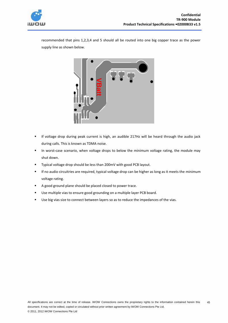
Confidential
TR-900 Module Product Technical Specifications •02000B33 v1.5
All specifications are correct at the time of release. iWOW Connections owns the proprietary rights to the information contained herein this
document. It may not be edited, copied or circulated without prior written agreement by iWOW Connections Pte Ltd.
© 2011, 2012 iWOW Connections Pte Ltd
45
recommended that pins 1,2,3,4 and 5 should all be routed into one big copper trace as the power
supply line as shown below.
If voltage drop during peak current is high, an audible 217Hz will be heard through the audio jack
during calls. This is known as TDMA noise.
In worst-case scenario, when voltage drops to below the minimum voltage rating, the module may
shut down.
Typical voltage drop should be less than 200mV with good PCB layout.
If no audio circuitries are required, typical voltage drop can be higher as long as it meets the minimum
voltage rating.
A good ground plane should be placed closed to power trace.
Use multiple vias to ensure good grounding on a multiple layer PCB board.
Use big vias size to connect between layers so as to reduce the impedances of the vias.
VB
att

Confidential
TR-900 Module Product Technical Specifications •02000B33 v1.5
All specifications are correct at the time of release. iWOW Connections owns the proprietary rights to the information contained herein this
document. It may not be edited, copied or circulated without prior written agreement by iWOW Connections Pte Ltd.
© 2011, 2012 iWOW Connections Pte Ltd
46
7 Incoming Inspection Criteria for TR-900 Module

Confidential
TR-900 Module Product Technical Specifications •02000B33 v1.5
All specifications are correct at the time of release. iWOW Connections owns the proprietary rights to the information contained herein this
document. It may not be edited, copied or circulated without prior written agreement by iWOW Connections Pte Ltd.
© 2011, 2012 iWOW Connections Pte Ltd
47
7.1 Logistics Inspection
a) Packaging correctness i. Model No and Label
Check that the TR-900 modules have labels pasted on them. These labels should display the
model number, IMEI and serial number.
ii. Quantity Ensure that the quantity is accurate.
iii. Status of packaging Check that the module is packed into box in a face up position as shown in the picture below.

Confidential
TR-900 Module Product Technical Specifications •02000B33 v1.5
All specifications are correct at the time of release. iWOW Connections owns the proprietary rights to the information contained herein this
document. It may not be edited, copied or circulated without prior written agreement by iWOW Connections Pte Ltd.
© 2011, 2012 iWOW Connections Pte Ltd
48
b) Physical Inspection i. 60 Pin Connector ii. Shield Cover iii. RF Receptacle
Note: Ensure that the following parts are intact and no visible physical damages.
c) Firmware Correctness i. Correct firmware loaded
You can check the firmware by typing ‘AT+CGMR’ when communicating with the modules.
8 Storage Conditions
The TR-900 modules can be stored under the following conditions:
Storage Temperature Range: -40° C to +85° C.
RF Receptacle
60-pin connector

Confidential
TR-900 Module Product Technical Specifications •02000B33 v1.5
All specifications are correct at the time of release. iWOW Connections owns the proprietary rights to the information contained herein this
document. It may not be edited, copied or circulated without prior written agreement by iWOW Connections Pte Ltd.
© 2011, 2012 iWOW Connections Pte Ltd
49
9 Packaging Information
Description: Conductive Box with Trays
Box Size: 344 x 230 x 68 (H)mm
Box Material: Single Wall – 275k/275k
Box Print: Conductive Ink Coating
Quantity: 150 pcs TR-900 modules

Confidential
TR-900 Module Product Technical Specifications •02000B33 v1.5
All specifications are correct at the time of release. iWOW Connections owns the proprietary rights to the information contained herein this
document. It may not be edited, copied or circulated without prior written agreement by iWOW Connections Pte Ltd.
© 2011, 2012 iWOW Connections Pte Ltd
50
10 Labeling Information
10.1 Module Box Label
The following information is labeled on the Module Box.
Model No. IMEI Range Firmware Qty Baud rate
10.2 Module Label
Please note that the module label displays the model number, barcode, IMEI, serial number, and place of
origin followed by the CE code and FCC ID.

Confidential
TR-900 Module Product Technical Specifications •02000B33 v1.5
All specifications are correct at the time of release. iWOW Connections owns the proprietary rights to the information contained herein this
document. It may not be edited, copied or circulated without prior written agreement by iWOW Connections Pte Ltd.
© 2011, 2012 iWOW Connections Pte Ltd
51
11 Caution Display – Handling
TR-900C is ESD sensitive (Voltage < 1kV) and require special ESD precautions typically applied to ESD sensitive
components.
It is recommended to use standard ESD precautions, as described in the following norm:
Always discharge before entering ESD area.
Operator handling the product should use a grounded wrist strap with good skin contact
Isolative footwear should also be worn to prevent static discharge flowing from body to ground.
Parts should be placed on approved static dissipative materials.
A static control workstation should be provided with ESD protective work surface and proper grounding.
Proper hand tools, ie.pliers, tweezers should be used when handling products.
Soldering iron should have the tip properly grounded.
Static control area should be made available for movements and transportation of product between 2
points.
Recommended humidity should be between 30% - 70%
Wear proper clothing and garments in an ESD environment.
For more information on ESD, please refer to ANSI/ESD S20.20
* Improper ESD control and poor handling will result in electrical failure and reliability problems

Confidential
TR-900 Module Product Technical Specifications •02000B33 v1.5
All specifications are correct at the time of release. iWOW Connections owns the proprietary rights to the information contained herein this
document. It may not be edited, copied or circulated without prior written agreement by iWOW Connections Pte Ltd.
© 2011, 2012 iWOW Connections Pte Ltd
52
12 Assembly Process
This section gives recommendations for the industrial assembly of the module on the application.
12.1 60 pin Connector Insertion Process Insert the module connector onto the application connector gently till you hear a click.
12.2 Soldering of legs The legs of the module should be soldered according to the following instructions:
The type and size of connection holes should be designed according to iWOW’s recommendation (see Appendix for mechanical drawing)
The quality of the soldering must be in accordance with the IPC-A-610 Rev-D
12.2.1 Hand soldering Please note the following instruction when performing hand soldering.
1. Assemble the module on the application 2. Make sure that a click is heard when inserting the 60-pin connector on TR-900 onto connector on
application board 3. Solder the 4 legs on the other side of the application board 4. Check with a scope the quality of the solder
12.3 RF connection There are three ways to interface an antenna to the RF connection of the module:
1. Connect the antenna to the module through the coaxial RF receptacle provided on the bottom side of the module
2. Connect the antenna to the module on the RF pad with a coaxial cable 3. Connect the antenna to the module on the RF pad with a spring contact
12.3.1 Connection via the coaxial RF receptacle A coaxial RF receptacle is provided on the bottom side of the module.
Supplier: Harwin Part number: UMCR-2250005R
The following are some options for cable assemblies compatible to the RF receptacle from Harwin:
UMCA-XXXXX-000
UMCA-XXXXX1-035

Confidential
TR-900 Module Product Technical Specifications •02000B33 v1.5
All specifications are correct at the time of release. iWOW Connections owns the proprietary rights to the information contained herein this
document. It may not be edited, copied or circulated without prior written agreement by iWOW Connections Pte Ltd.
© 2011, 2012 iWOW Connections Pte Ltd
53
12.3.2 Connection to the RF pad by soldering with a coaxial cable
The antenna can be connected to the module through a coaxial cable. The cable is connected to both the RF
pad and the Ground pad.
The cable is recommended to be soldered as described on the mechanical drawing on the following page.
Notes:
1 Always use a coaxial cable for connecting antenna to module.
2 Shielding of the coaxial cable must be done by soldering onto ground pad of module.
3 Coaxial cable should be as short as possible.
4 Soldering of coaxial cable should be done according to the recommended cable soldering specifications.
5 It is recommended to use XXXXX or RG178 coaxial cable or equivalent.
RF PAD
GROUND
PAD
Solder the shielding of the coaxial cable to the Ground Pad
Solder the core of the coaxial cable to the RF Pad

Confidential
TR-900 Module Product Technical Specifications •02000B33 v1.5
All specifications are correct at the time of release. iWOW Connections owns the proprietary rights to the information contained herein this
document. It may not be edited, copied or circulated without prior written agreement by iWOW Connections Pte Ltd.
© 2011, 2012 iWOW Connections Pte Ltd
54
12.3.3 Connection to the RF pad with a spring contact
The antenna can be connected to the module on the RF pad by using a spring contact as shown below.
There are no standard spring contacts available for the TR-900 module. As such, this solution requires a
specific part to be developed.
To Antenna
Contact on RF Pad

Confidential
TR-900 Module Product Technical Specifications •02000B33 v1.5
All specifications are correct at the time of release. iWOW Connections owns the proprietary rights to the information contained herein this
document. It may not be edited, copied or circulated without prior written agreement by iWOW Connections Pte Ltd.
© 2011, 2012 iWOW Connections Pte Ltd
55
13 Rework and Module Exchange Process
The following is the rework and module exchange process.
1. Locate the legs to unsolder 2. Set the temperature of the soldering station accordingly 3. With the use of solder wick and the soldering iron, remove the solder from the leg and soldering pad. 4. Repeat the procedure for each leg 5. Remove the module gently. 6. Check that the there is no solder left and that the pads are OK. 7. Clean the pads, if necessary, with soldering or solder wick. 8. To solder a new module, refer to Chapter 12.
Note: The temperature of the Iron must not exceed the 350oC over 3 seconds, to comply with Lead-Free
soldering. Recommendation of the solder paste manufacturer should be taken into consideration to ensure a proper
process.


Confidential
TR-900 Module Product Technical Specifications •02000B33 v1.5
All specifications are correct at the time of release. iWOW Connections owns the proprietary rights to the information contained herein this
document. It may not be edited, copied or circulated without prior written agreement by iWOW Connections Pte Ltd. © 2011, 2012 iWOW
Connections Pte Ltd
57
15 SUPPORT/ CONTACT US
For distributor clients, please contact your respective distributor FAE.
For direct clients, please contact iWOW FAE (Technical Support Department) or email us at
For general enquiries please contact us at:
iWOW Connections Pte Ltd
1 Lorong 2 Toa Payoh, #04-01
Yellow Pages Building
Singapore 319637
Office: (65) 6748 8123
Fax : (65) 6748 2668
Email: [email protected]
Website: http://www.iWOW.com.sg