Embed Size (px)
Citation preview
�1.5L 4-CYL - VIN [E]
�1994 Toyota Paseo
1994 ENGINES Toyota 1.5L 4-Cylinder
Paseo
NOTE: For repair procedures not covered in this article, see ENGINE OVERHAUL PROCEDURES - GENERAL INFORMATION article in GENERAL INFORMATION.
ENGINE IDENTIFICATION
Engine serial number is stamped on left rear corner ofcylinder block. See Fig. 1.
ENGINE IDENTIFICATION CODE TABLE���������������������������������������������������������������������������������������������������Engine Code
1.5L 4-Cylinder .......................... 5E-FE���������������������������������������������������������������������������������������������������
Fig. 1: Identifying Engine Serial NumberCourtesy of Toyota Motor Sales, U.S.A., Inc.
ADJUSTMENTS
VALVE CLEARANCE ADJUSTMENT
NOTE: Adjust valve clearance with engine cold.
1) Disconnect PCV hose, necessary electrical connections andspark plug wires to access valve cover. Remove nuts, seal washers,valve cover and gasket. 2) Rotate crankshaft clockwise so cylinder No. 1 is at TDC oncompression stroke. Cylinder No. 1 is front cylinder at timing beltend of engine. Ensure timing mark on crankshaft pulley aligns with "0"mark on timing belt cover. 3) Ensure valve lifters on cylinder No. 1 are loose and valvelifters on cylinder No. 4 are tight. If conditions are not asdescribed, rotate crankshaft clockwise one complete revolution (360degrees). 4) Using feeler gauge, measure valve clearance between valvelifter and camshaft on intake valves of cylinders No. 1 and 2, andexhaust valves of cylinders No. 1 and 3. Record valve clearance.Rotate crankshaft clockwise one complete revolution (360 degrees). 5) Measure and record valve clearance on intake valves ofcylinders No. 3 and 4, and exhaust valves of cylinders No. 2 and 4.Ensure valve clearance is within specification. See VALVE CLEARANCESPECIFICATIONS table.
VALVE CLEARANCE SPECIFICATIONS TABLE (1)���������������������������������������������������������������������������������������������������Application In. (mm)
Exhaust Valve .............. .012-.016 (.31-.41)Intake Valve ............... .006-.010 (.15-.25)
(1) - Adjust valve clearance with engine cold.���������������������������������������������������������������������������������������������������
6) If valve clearance requires adjustment, rotate camshaft solobe on valve to be adjusted is facing upward, away from valve lifter.Position notch area on valve lifter toward inside of cylinder head. DONOT align notch area with camshaft. Use Valve Clearance Adjuster (SST09248-55040) to adjust valve clearance. 7) Using SST "A" of valve clearance adjuster, push downwardon valve lifter. Place SST "B" between camshaft and valve lifter. SeeFig. 2. Ensure enough clearance exists for adjusting shim removal.Remove SST "A".
Fig. 2: Adjusting Valve ClearanceCourtesy of Toyota Motor Sales, U.S.A., Inc.
8) Using small screwdriver and magnet, remove adjusting shim.Measure and record thickness of removed shim. Using measured clearance
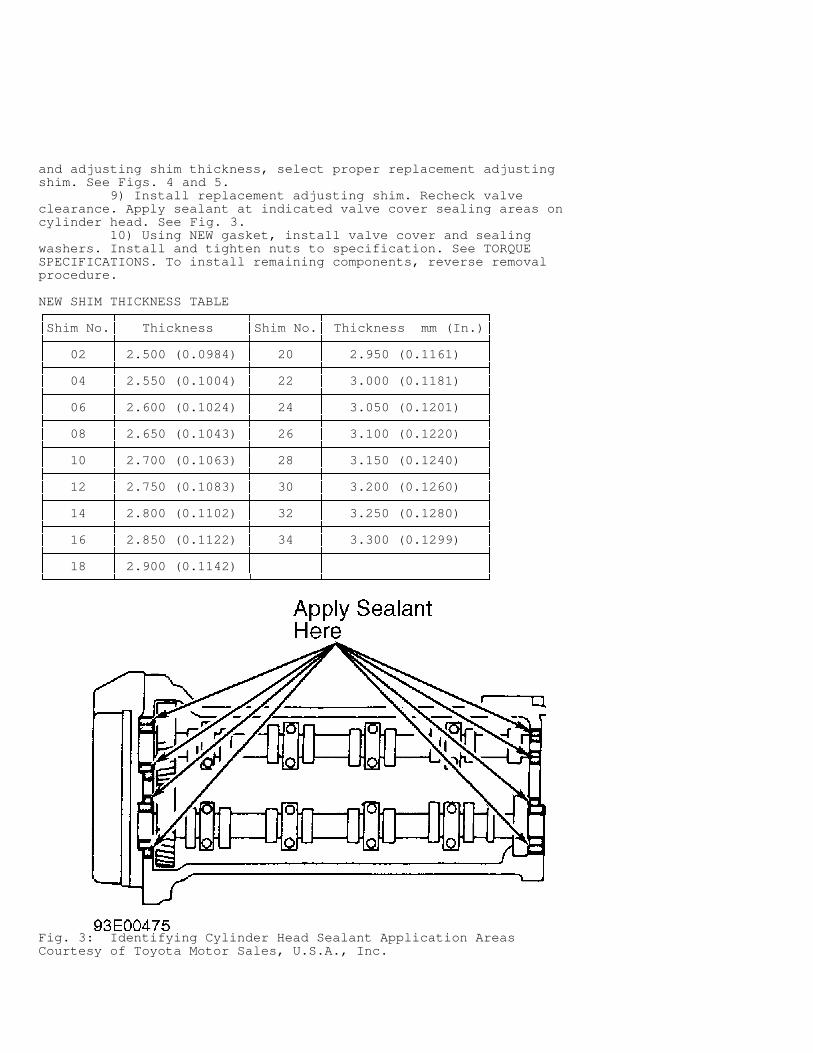
and adjusting shim thickness, select proper replacement adjustingshim. See Figs. 4 and 5. 9) Install replacement adjusting shim. Recheck valveclearance. Apply sealant at indicated valve cover sealing areas oncylinder head. See Fig. 3. 10) Using NEW gasket, install valve cover and sealingwashers. Install and tighten nuts to specification. See TORQUESPECIFICATIONS. To install remaining components, reverse removalprocedure.
NEW SHIM THICKNESS TABLE������������������������������������������������������������������������������������������������������������������Shim No.
� Thickness
�Shim No.
� Thickness mm (In.)
�� ��������������������������������������������������������������������������������������������������������������� 02
� 2.500 (0.0984)
� 20
� 2.950 (0.1161)
�� ��������������������������������������������������������������������������������������������������������������� 04
� 2.550 (0.1004)
� 22
� 3.000 (0.1181)
�� ��������������������������������������������������������������������������������������������������������������� 06
� 2.600 (0.1024)
� 24
� 3.050 (0.1201)
�� ��������������������������������������������������������������������������������������������������������������� 08
� 2.650 (0.1043)
� 26
� 3.100 (0.1220)
�� ��������������������������������������������������������������������������������������������������������������� 10
� 2.700 (0.1063)
� 28
� 3.150 (0.1240)
�� ��������������������������������������������������������������������������������������������������������������� 12
� 2.750 (0.1083)
� 30
� 3.200 (0.1260)
�� ��������������������������������������������������������������������������������������������������������������� 14
� 2.800 (0.1102)
� 32
� 3.250 (0.1280)
�� ��������������������������������������������������������������������������������������������������������������� 16
� 2.850 (0.1122)
� 34
� 3.300 (0.1299)
�� ��������������������������������������������������������������������������������������������������������������� 18
� 2.900 (0.1142)
�
�
� ���������������������������������������������������������������������������������������������������������������
Fig. 3: Identifying Cylinder Head Sealant Application AreasCourtesy of Toyota Motor Sales, U.S.A., Inc.
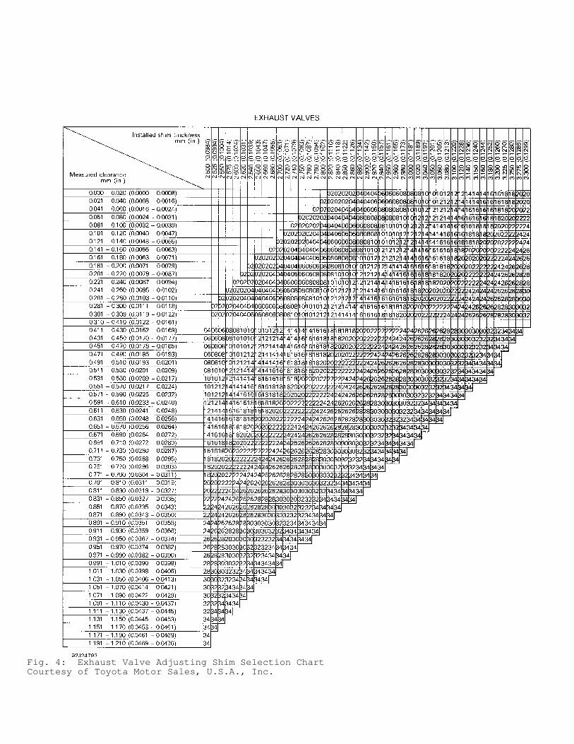
Fig. 4: Exhaust Valve Adjusting Shim Selection ChartCourtesy of Toyota Motor Sales, U.S.A., Inc.
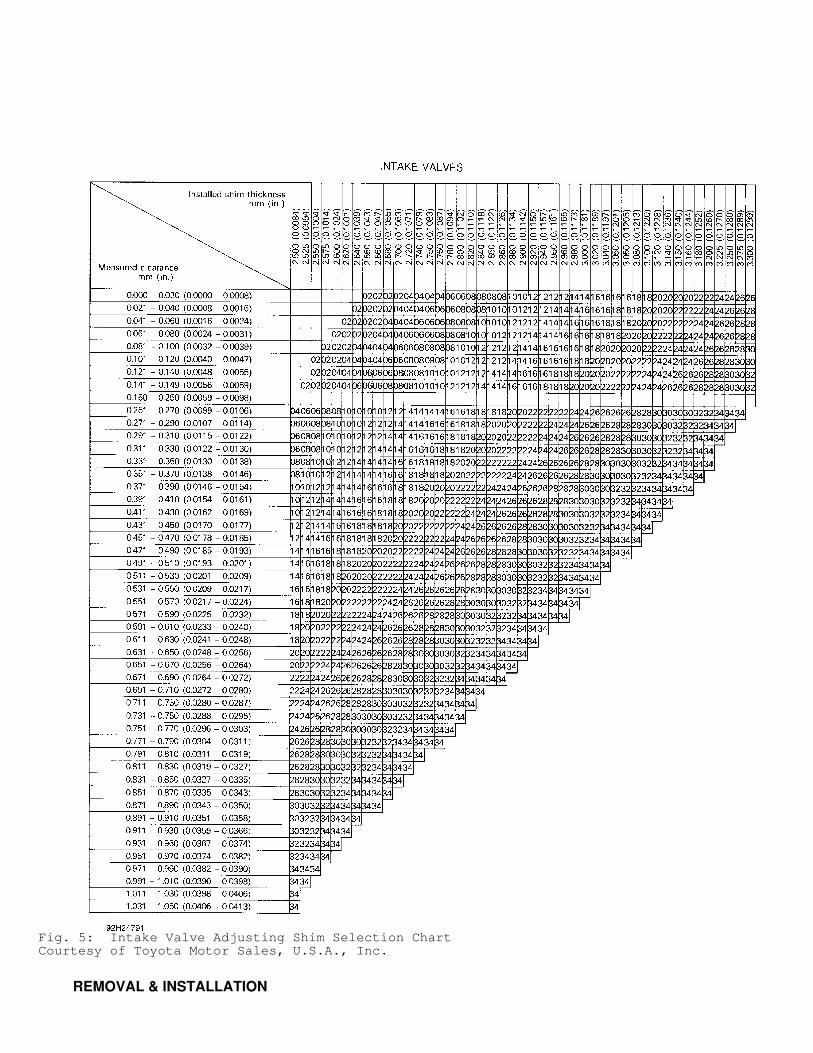
Fig. 5: Intake Valve Adjusting Shim Selection ChartCourtesy of Toyota Motor Sales, U.S.A., Inc.
REMOVAL & INSTALLATION
NOTE: For reassembly reference, label all electrical connectors, vacuum hoses and fuel lines before removal. Also place mating marks on engine hood and other major assemblies before removal.
WARNING: To prevent air bag deployment, disconnect negative battery cable at least 90 seconds before working on vehicle.
CAUTION: When battery is disconnected, vehicle computer and memory systems may lose memory data. Driveability problems may exist until computer systems have completed a relearn cycle.
FUEL PRESSURE RELEASE
With ignition off, disconnect negative battery cable. Placesuitable container under fuel line. Cover fuel line connection withshop towel. Slowly loosen fuel line connection to release fuelpressure. Once fuel pressure is released, fuel system components maybe serviced.
ENGINE
NOTE: Remove engine and transaxle as an assembly.
Removal 1) Disconnect negative battery cable. Release fuel pressure.See FUEL PRESSURE RELEASE. Drain cooling system and engine oil. Removehood, battery, coolant reservoir and radiator. 2) Remove air cleaner assembly with air intake connector andair cleaner bracket. Disconnect control cables at throttle body. 3) Remove charcoal canister and drain canister. Draincanister is connected to charcoal canister with a hose and is locatednear charcoal canister. 4) Disconnect necessary electrical connections, coolanthoses, fuel lines and vacuum hoses. Remove cruise control actuator (ifequipped) from passenger-side front fender. 5) Remove bolt and vacuum switching valve assembly, locatednear front of timing belt cover, on passenger’s side. Raise andsupport vehicle. Remove lower engine covers. 6) Disconnect necessary electrical connections, controlcables, oil cooler lines and speedometer cable from transaxle.Disconnect oxygen sensor connector. Remove exhaust pipe-to-cylinderblock support bracket bolts. Remove nuts, and separate exhaust pipefrom exhaust manifold. 7) On M/T models, remove clutch release cylinder with hoseattached and secure aside. On all models, remove power steering pumpand A/C compressor (if equipped) with hoses attached and secure aside.Remove power steering pump adjusting bracket and A/C compressormounting bracket (if equipped). 8) On A/C equipped models without power steering, remove A/Cidler pulley. On all models, remove front wheels. Drain transaxlefluid. Remove cotter pin and retainer from end of axle shaft. Applybrakes and remove axle shaft nut. 9) Remove nut and separate tie rod from steering knuckle.Remove ball joint-to-lower control arm bolts/nuts. Separate lowercontrol arm from ball joint. 10) Cover axle shaft boot with shop towel. Attach Puller (SST09950-20017) to front hub, and press axle shaft from hub assembly.Push hub assembly outward. Separate axle shaft from hub assembly. 11) Using hammer and brass drift, tap axle shaft fromtransaxle. See Fig. 6. Support engine with hoist. Remove through-boltand rear (firewall side) engine mount bracket.
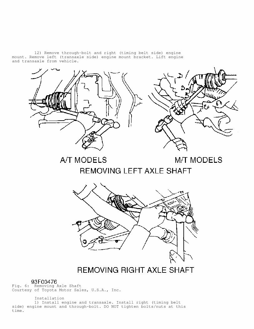
12) Remove through-bolt and right (timing belt side) enginemount. Remove left (transaxle side) engine mount bracket. Lift engineand transaxle from vehicle.
Fig. 6: Removing Axle ShaftCourtesy of Toyota Motor Sales, U.S.A., Inc.
Installation 1) Install engine and transaxle. Install right (timing beltside) engine mount and through-bolt. DO NOT tighten bolts/nuts at thistime.
NOTE: Ensure ground strap is connected to left (transaxle side) engine mount bracket.
2) Install left (transaxle side) engine mount bracket.Tighten bolts to specification. See TORQUE SPECIFICATIONS. Installrear (firewall side) engine mount bracket and through-bolt. Tightenbolts to specification. 3) With all other engine mount bolts tightened tospecification, tighten right (timing belt side) engine mountbolts/nuts and through-bolt to specification. See TORQUESPECIFICATIONS. 4) Install NEW snap ring on end of axle shaft. Coat lip ofaxle shaft seal with grease. Install axle shaft in transaxle withopening of snap ring facing downward. 5) Ensure axle shaft moves in and out .079-.120" (2.00-3.00mm) after installation. Ensure axle shaft cannot be pulled fromtransaxle. 6) To install remaining components, reverse removalprocedure. Install NEW exhaust pipe-to-exhaust manifold nuts. Tightenfasteners to specification. See TORQUE SPECIFICATIONS. Adjust fluidlevels and control cables.
CYLINDER HEAD & MANIFOLDS
Removal 1) Disconnect negative battery cable. Release fuel pressure.See FUEL PRESSURE RELEASE. Drain cooling system. Disconnect controlcables at throttle body. 2) Remove air cleaner assembly with air intake connector.Disconnect necessary electrical connections, coolant hoses, fuellines, vacuum lines and PCV hose. 3) Remove A/C compressor and power steering pump (ifequipped) with hoses attached and secure aside. Remove power steeringpump bracket. On models equipped with A/C without power steering,remove A/C idler pulley. 4) On all models, remove distributor and spark plugs. RemoveEGR pipe, EGR valve, EGR valve vacuum modulator, EGR temperaturesensor (if equipped) and coolant housing. See Fig. 7. Raise andsupport vehicle. Remove right lower engine cover.
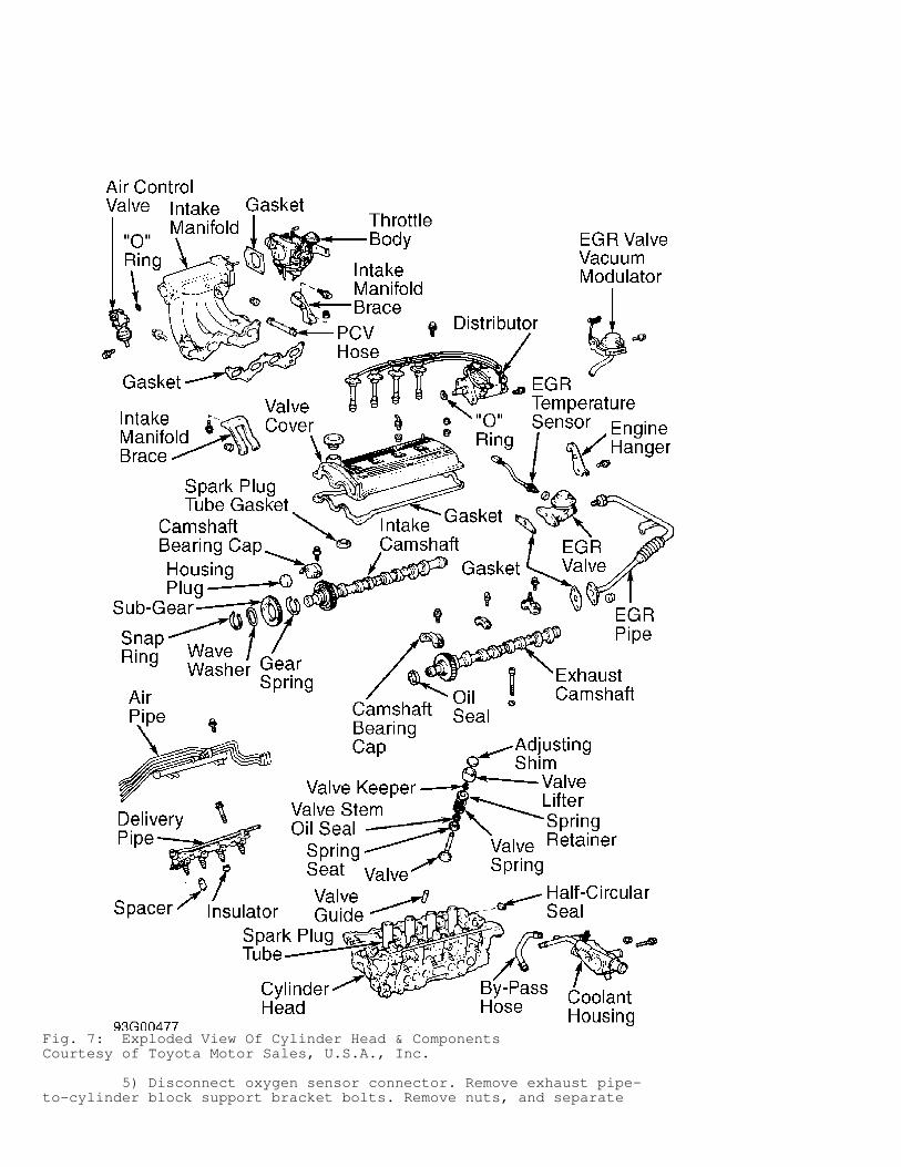
Fig. 7: Exploded View Of Cylinder Head & ComponentsCourtesy of Toyota Motor Sales, U.S.A., Inc.
5) Disconnect oxygen sensor connector. Remove exhaust pipe-to-cylinder block support bracket bolts. Remove nuts, and separate
exhaust pipe from exhaust manifold. 6) Remove exhaust manifold heat insulator. Remove nuts,exhaust manifold and gasket. Remove air control valve and "O" ringfrom end of intake manifold and air pipe. See Fig. 7.
CAUTION: DO NOT allow injectors to fall from delivery pipe when removing from intake manifold.
7) Remove throttle body and gasket from intake manifold (ifnecessary). Remove intake manifold braces. Disconnect fuel lines fromdelivery pipe and electrical connections from injectors. Remove bolts,delivery pipe with injectors, spacers and insulators. See Fig. 7. 8) Remove air pipe. See Fig. 7. Remove bolts/nuts, intakemanifold and gasket. Remove nuts, seal washers, valve cover andgasket. 9) Remove timing belt from camshaft sprocket and No. 2 idlerpulley. See TIMING BELT. Remove camshafts. See CAMSHAFT.
CAUTION: Cylinder head bolts must be loosened in proper sequence to prevent cylinder head warpage.
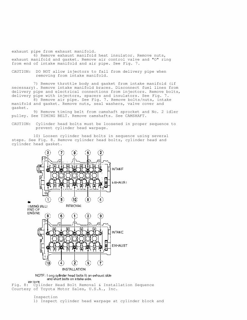
10) Loosen cylinder head bolts in sequence using severalsteps. See Fig. 8. Remove cylinder head bolts, cylinder head andcylinder head gasket.
Fig. 8: Cylinder Head Bolt Removal & Installation SequenceCourtesy of Toyota Motor Sales, U.S.A., Inc.
Inspection 1) Inspect cylinder head warpage at cylinder block and
manifold areas. Replace cylinder head if warpage exceedsspecification. See CYLINDER HEAD table under ENGINE SPECIFICATIONS. 2) Inspect intake manifold-to-cylinder head surfaces forwarpage. Replace intake manifold if warpage exceeds .0039" (.100 mm). 3) Inspect exhaust manifold-to-cylinder head surface warpage.Replace exhaust manifold if warpage exceeds .0079" (.200 mm). 4) Inspect cylinder block deck surface for warpage. Replacecylinder block if deck warpage exceeds specification. See CYLINDERBLOCK table under ENGINE SPECIFICATIONS. Inspect camshaft andcomponents. See CAMSHAFT.
Installation 1) Install NEW cylinder head gasket on cylinder block. Ensureall holes in cylinder head gasket align with holes in cylinder block.Install cylinder head. Apply engine oil on cylinder head bolt threadsand cylinder head bolt-to-cylinder head contact surfaces. 2) Install and tighten cylinder head bolts to specificationin sequence. See Fig. 8. See TORQUE SPECIFICATIONS. Install camshaftsusing proper procedure. See CAMSHAFT. 3) To install remaining components, reverse removal procedureusing NEW gaskets and NEW "O" rings. If camshaft or cylinder headcomponents are serviced, adjust valve clearance. See VALVE CLEARANCEADJUSTMENT under ADJUSTMENTS. 4) If spark plug tube gasket in valve cover requiresreplacement, pry spark plug tube gasket from valve cover. Use care notto scratch valve cover sealing surface. 5) Using Handle (SST 09552-10010) and Gasket/Seal Installer(SST 09560-10010), install NEW spark plug tube gasket until it is evenwith upper edge of valve cover surface. Coat spark plug tube gasketsealing area with grease. 6) Before installing valve cover and gasket, apply sealant atindicated valve cover sealing areas on cylinder head. See Fig. 3.Using NEW gasket, install valve cover and sealing washers. Install andtighten nuts to specification. See TORQUE SPECIFICATIONS.
CAUTION: Install spacers below delivery pipe, with plastic end away from cylinder head and metal area toward cylinder head.
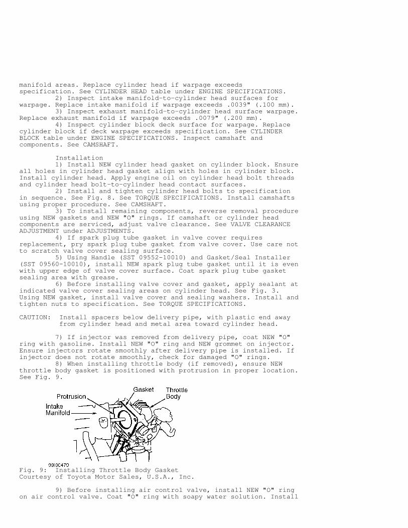
7) If injector was removed from delivery pipe, coat NEW "O"ring with gasoline. Install NEW "O" ring and NEW grommet on injector.Ensure injectors rotate smoothly after delivery pipe is installed. Ifinjector does not rotate smoothly, check for damaged "O" rings. 8) When installing throttle body (if removed), ensure NEWthrottle body gasket is positioned with protrusion in proper location.See Fig. 9.
Fig. 9: Installing Throttle Body GasketCourtesy of Toyota Motor Sales, U.S.A., Inc.
9) Before installing air control valve, install NEW "O" ringon air control valve. Coat "O" ring with soapy water solution. Install
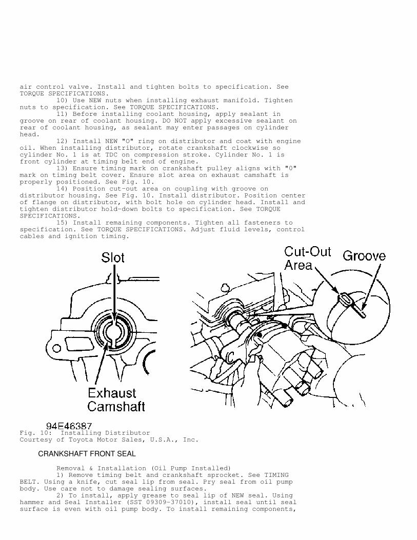
air control valve. Install and tighten bolts to specification. SeeTORQUE SPECIFICATIONS. 10) Use NEW nuts when installing exhaust manifold. Tightennuts to specification. See TORQUE SPECIFICATIONS. 11) Before installing coolant housing, apply sealant ingroove on rear of coolant housing. DO NOT apply excessive sealant onrear of coolant housing, as sealant may enter passages on cylinderhead. 12) Install NEW "O" ring on distributor and coat with engineoil. When installing distributor, rotate crankshaft clockwise socylinder No. 1 is at TDC on compression stroke. Cylinder No. 1 isfront cylinder at timing belt end of engine. 13) Ensure timing mark on crankshaft pulley aligns with "0"mark on timing belt cover. Ensure slot area on exhaust camshaft isproperly positioned. See Fig. 10. 14) Position cut-out area on coupling with groove ondistributor housing. See Fig. 10. Install distributor. Position centerof flange on distributor, with bolt hole on cylinder head. Install andtighten distributor hold-down bolts to specification. See TORQUESPECIFICATIONS. 15) Install remaining components. Tighten all fasteners tospecification. See TORQUE SPECIFICATIONS. Adjust fluid levels, controlcables and ignition timing.
Fig. 10: Installing DistributorCourtesy of Toyota Motor Sales, U.S.A., Inc.
CRANKSHAFT FRONT SEAL
Removal & Installation (Oil Pump Installed) 1) Remove timing belt and crankshaft sprocket. See TIMINGBELT. Using a knife, cut seal lip from seal. Pry seal from oil pumpbody. Use care not to damage sealing surfaces. 2) To install, apply grease to seal lip of NEW seal. Usinghammer and Seal Installer (SST 09309-37010), install seal until sealsurface is even with oil pump body. To install remaining components,
reverse removal procedure.
Removal & Installation (Oil Pump Removed) Pry seal from oil pump body. Using hammer and Seal Installer(SST 09309-37010), install NEW seal until seal surface is even withoil pump body. Apply grease to seal lip of seal.
TIMING BELT
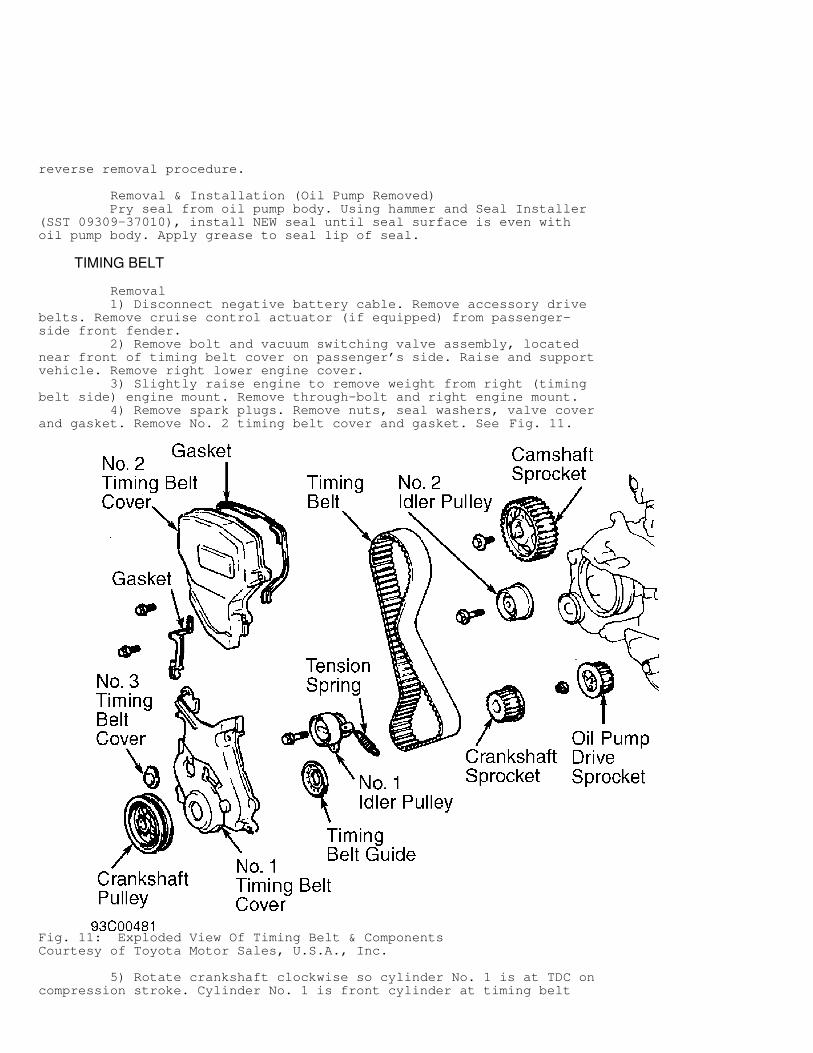
Removal 1) Disconnect negative battery cable. Remove accessory drivebelts. Remove cruise control actuator (if equipped) from passenger-side front fender. 2) Remove bolt and vacuum switching valve assembly, locatednear front of timing belt cover on passenger’s side. Raise and supportvehicle. Remove right lower engine cover. 3) Slightly raise engine to remove weight from right (timingbelt side) engine mount. Remove through-bolt and right engine mount. 4) Remove spark plugs. Remove nuts, seal washers, valve coverand gasket. Remove No. 2 timing belt cover and gasket. See Fig. 11.
Fig. 11: Exploded View Of Timing Belt & ComponentsCourtesy of Toyota Motor Sales, U.S.A., Inc.
5) Rotate crankshaft clockwise so cylinder No. 1 is at TDC oncompression stroke. Cylinder No. 1 is front cylinder at timing belt
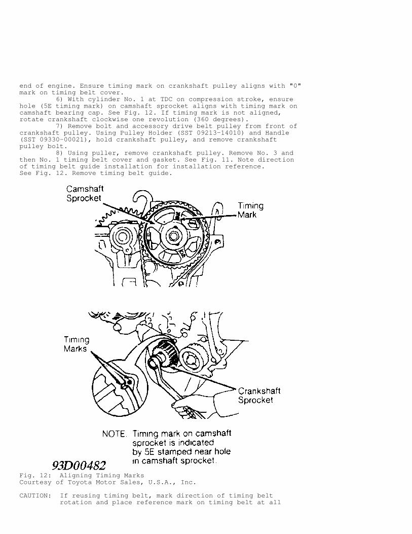
end of engine. Ensure timing mark on crankshaft pulley aligns with "0"mark on timing belt cover. 6) With cylinder No. 1 at TDC on compression stroke, ensurehole (5E timing mark) on camshaft sprocket aligns with timing mark oncamshaft bearing cap. See Fig. 12. If timing mark is not aligned,rotate crankshaft clockwise one revolution (360 degrees). 7) Remove bolt and accessory drive belt pulley from front ofcrankshaft pulley. Using Pulley Holder (SST 09213-14010) and Handle(SST 09330-00021), hold crankshaft pulley, and remove crankshaftpulley bolt. 8) Using puller, remove crankshaft pulley. Remove No. 3 andthen No. 1 timing belt cover and gasket. See Fig. 11. Note directionof timing belt guide installation for installation reference.See Fig. 12. Remove timing belt guide.
Fig. 12: Aligning Timing MarksCourtesy of Toyota Motor Sales, U.S.A., Inc.
CAUTION: If reusing timing belt, mark direction of timing belt rotation and place reference mark on timing belt at all
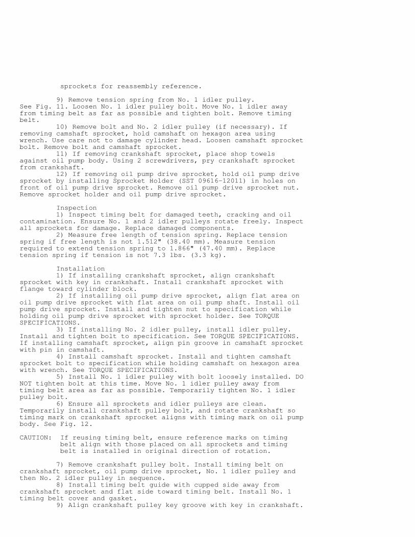
sprockets for reassembly reference.
9) Remove tension spring from No. 1 idler pulley.See Fig. 11. Loosen No. 1 idler pulley bolt. Move No. 1 idler awayfrom timing belt as far as possible and tighten bolt. Remove timingbelt. 10) Remove bolt and No. 2 idler pulley (if necessary). Ifremoving camshaft sprocket, hold camshaft on hexagon area usingwrench. Use care not to damage cylinder head. Loosen camshaft sprocketbolt. Remove bolt and camshaft sprocket. 11) If removing crankshaft sprocket, place shop towelsagainst oil pump body. Using 2 screwdrivers, pry crankshaft sprocketfrom crankshaft. 12) If removing oil pump drive sprocket, hold oil pump drivesprocket by installing Sprocket Holder (SST 09616-12011) in holes onfront of oil pump drive sprocket. Remove oil pump drive sprocket nut.Remove sprocket holder and oil pump drive sprocket.
Inspection 1) Inspect timing belt for damaged teeth, cracking and oilcontamination. Ensure No. 1 and 2 idler pulleys rotate freely. Inspectall sprockets for damage. Replace damaged components. 2) Measure free length of tension spring. Replace tensionspring if free length is not 1.512" (38.40 mm). Measure tensionrequired to extend tension spring to 1.866" (47.40 mm). Replacetension spring if tension is not 7.3 lbs. (3.3 kg).
Installation 1) If installing crankshaft sprocket, align crankshaftsprocket with key in crankshaft. Install crankshaft sprocket withflange toward cylinder block. 2) If installing oil pump drive sprocket, align flat area onoil pump drive sprocket with flat area on oil pump shaft. Install oilpump drive sprocket. Install and tighten nut to specification whileholding oil pump drive sprocket with sprocket holder. See TORQUESPECIFICATIONS. 3) If installing No. 2 idler pulley, install idler pulley.Install and tighten bolt to specification. See TORQUE SPECIFICATIONS.If installing camshaft sprocket, align pin groove in camshaft sprocketwith pin in camshaft. 4) Install camshaft sprocket. Install and tighten camshaftsprocket bolt to specification while holding camshaft on hexagon areawith wrench. See TORQUE SPECIFICATIONS. 5) Install No. 1 idler pulley with bolt loosely installed. DONOT tighten bolt at this time. Move No. 1 idler pulley away fromtiming belt area as far as possible. Temporarily tighten No. 1 idlerpulley bolt. 6) Ensure all sprockets and idler pulleys are clean.Temporarily install crankshaft pulley bolt, and rotate crankshaft sotiming mark on crankshaft sprocket aligns with timing mark on oil pumpbody. See Fig. 12.
CAUTION: If reusing timing belt, ensure reference marks on timing belt align with those placed on all sprockets and timing belt is installed in original direction of rotation.
7) Remove crankshaft pulley bolt. Install timing belt oncrankshaft sprocket, oil pump drive sprocket, No. 1 idler pulley andthen No. 2 idler pulley in sequence. 8) Install timing belt guide with cupped side away fromcrankshaft sprocket and flat side toward timing belt. Install No. 1timing belt cover and gasket. 9) Align crankshaft pulley key groove with key in crankshaft.
Install crankshaft pulley. Install and tighten crankshaft pulley boltto specification while holding crankshaft pulley with pulley holderand handle. See TORQUE SPECIFICATIONS. 10) Install accessory drive belt pulley on front ofcrankshaft pulley. Install and tighten bolts to specification. SeeTORQUE SPECIFICATIONS. 11) Rotate crankshaft clockwise so cylinder No. 1 is at TDCon compression stroke. Ensure timing mark on crankshaft pulley alignswith "0" mark on timing belt cover.
CAUTION: If reusing timing belt, ensure reference on timing belt aligns with that on camshaft sprocket.
12) Rotate camshaft sprocket, and align hole (5E timing mark)on camshaft sprocket with timing mark on camshaft bearing cap. SeeFig. 12. Install timing belt on camshaft sprocket. Ensure tensionexists on timing belt between crankshaft sprocket, oil pump drivesprocket and camshaft sprocket.
CAUTION: Crankshaft must always be rotated clockwise. DO NOT rotate crankshaft counterclockwise.
13) Loosen No. 1 idler pulley bolt, allowing tension springto move No. 1 idler pulley against timing belt. Rotate crankshaftclockwise 2 full revolutions from TDC to TDC. 14) Ensure hole (5E timing mark) on camshaft sprocket alignswith timing mark on camshaft bearing cap when timing mark oncrankshaft pulley aligns with "0" mark on timing belt cover. If timingmarks are not aligned, remove and reinstall timing belt. 15) Tighten No. 1 idler pulley bolt to specification. SeeTORQUE SPECIFICATIONS. Install No. 2 and 3 timing belt covers andgaskets. Apply sealant at indicated valve cover sealing areas oncylinder head. See Fig. 3. 16) Using NEW gasket, install valve cover and sealingwashers. Install and tighten nuts to specification. See TORQUESPECIFICATIONS. 17) To install remaining components, reverse removalprocedure. To ensure proper mount alignment, install all right (timingbelt side) engine mount bolts/nuts before tightening to specification.See TORQUE SPECIFICATIONS.
VALVE LIFTER
Removal Remove camshaft. See CAMSHAFT. Note location of adjustingshims and valve lifters for reassembly reference. Remove adjustingshims and valve lifters from cylinder head.
Inspection Inspect components for damage. Measure valve lifter diameterand bore diameter. Ensure oil clearance is within specification.Replace components if not within specification. See VALVE LIFTERStable under ENGINE SPECIFICATIONS.
Installation To install, reverse removal procedure. Ensure components areinstalled in original locations. If camshaft, adjusting shims or valvelifters are replaced, check valve clearance. See VALVE CLEARANCEADJUSTMENT under ADJUSTMENTS.
CAMSHAFT
Removal
1) Remove timing belt and camshaft sprocket. See TIMING BELT.When removing exhaust camshaft, remove bolts and distributor.
CAUTION: Camshafts must be properly positioned to lift camshaft straight from cylinder head to prevent damage to cylinder head and camshaft. DO NOT pry or force camshafts from cylinder head, or component damage will result.
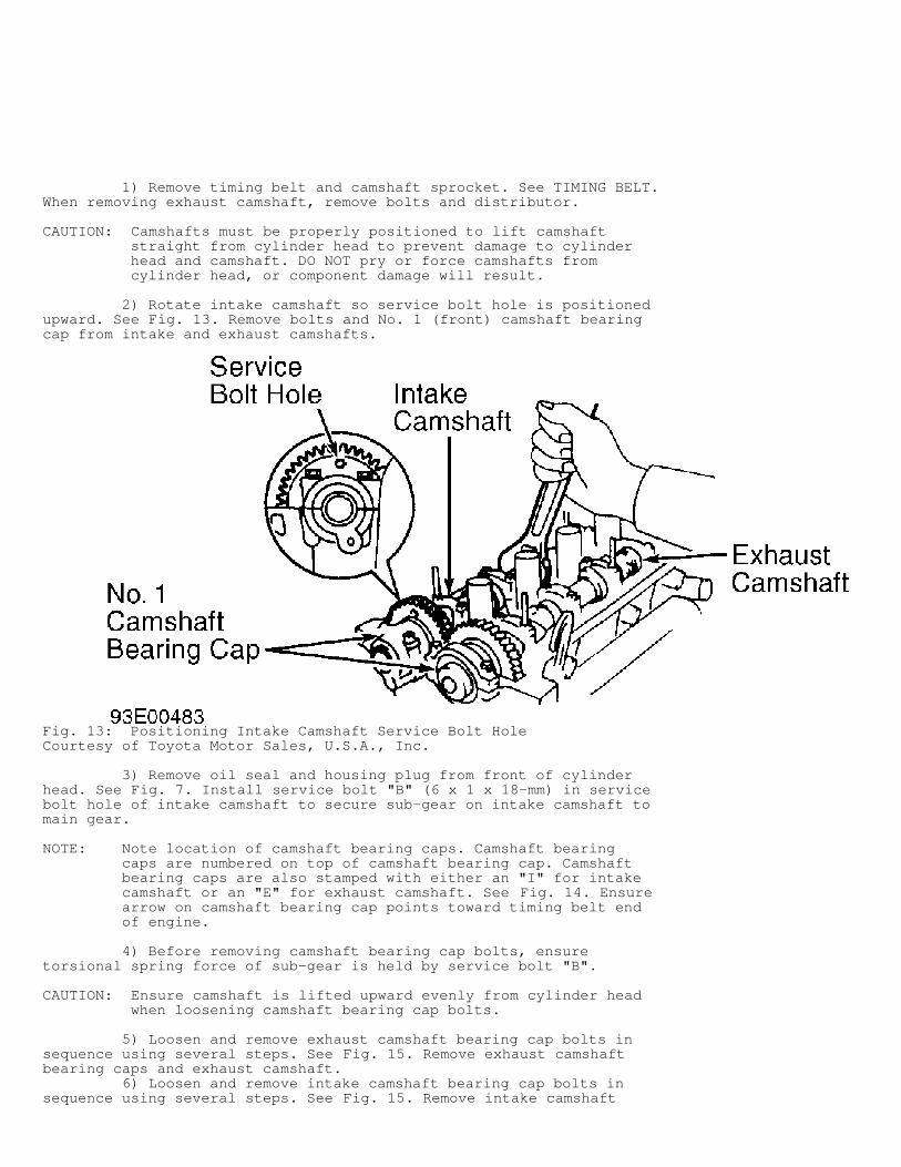
2) Rotate intake camshaft so service bolt hole is positionedupward. See Fig. 13. Remove bolts and No. 1 (front) camshaft bearingcap from intake and exhaust camshafts.
Fig. 13: Positioning Intake Camshaft Service Bolt HoleCourtesy of Toyota Motor Sales, U.S.A., Inc.
3) Remove oil seal and housing plug from front of cylinderhead. See Fig. 7. Install service bolt "B" (6 x 1 x 18-mm) in servicebolt hole of intake camshaft to secure sub-gear on intake camshaft tomain gear.
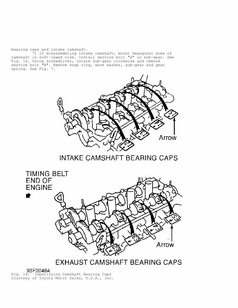
NOTE: Note location of camshaft bearing caps. Camshaft bearing caps are numbered on top of camshaft bearing cap. Camshaft bearing caps are also stamped with either an "I" for intake camshaft or an "E" for exhaust camshaft. See Fig. 14. Ensure arrow on camshaft bearing cap points toward timing belt end of engine.
4) Before removing camshaft bearing cap bolts, ensuretorsional spring force of sub-gear is held by service bolt "B".
CAUTION: Ensure camshaft is lifted upward evenly from cylinder head when loosening camshaft bearing cap bolts.
5) Loosen and remove exhaust camshaft bearing cap bolts insequence using several steps. See Fig. 15. Remove exhaust camshaftbearing caps and exhaust camshaft. 6) Loosen and remove intake camshaft bearing cap bolts insequence using several steps. See Fig. 15. Remove intake camshaft
bearing caps and intake camshaft. 7) If disassembling intake camshaft, mount hexagonal area ofcamshaft in soft-jawed vise. Install service bolt "A" in sub-gear. SeeFig. 16. Using screwdriver, rotate sub-gear clockwise and removeservice bolt "B". Remove snap ring, wave washer, sub-gear and gearspring. See Fig. 7.
Fig. 14: Identifying Camshaft Bearing CapsCourtesy of Toyota Motor Sales, U.S.A., Inc.
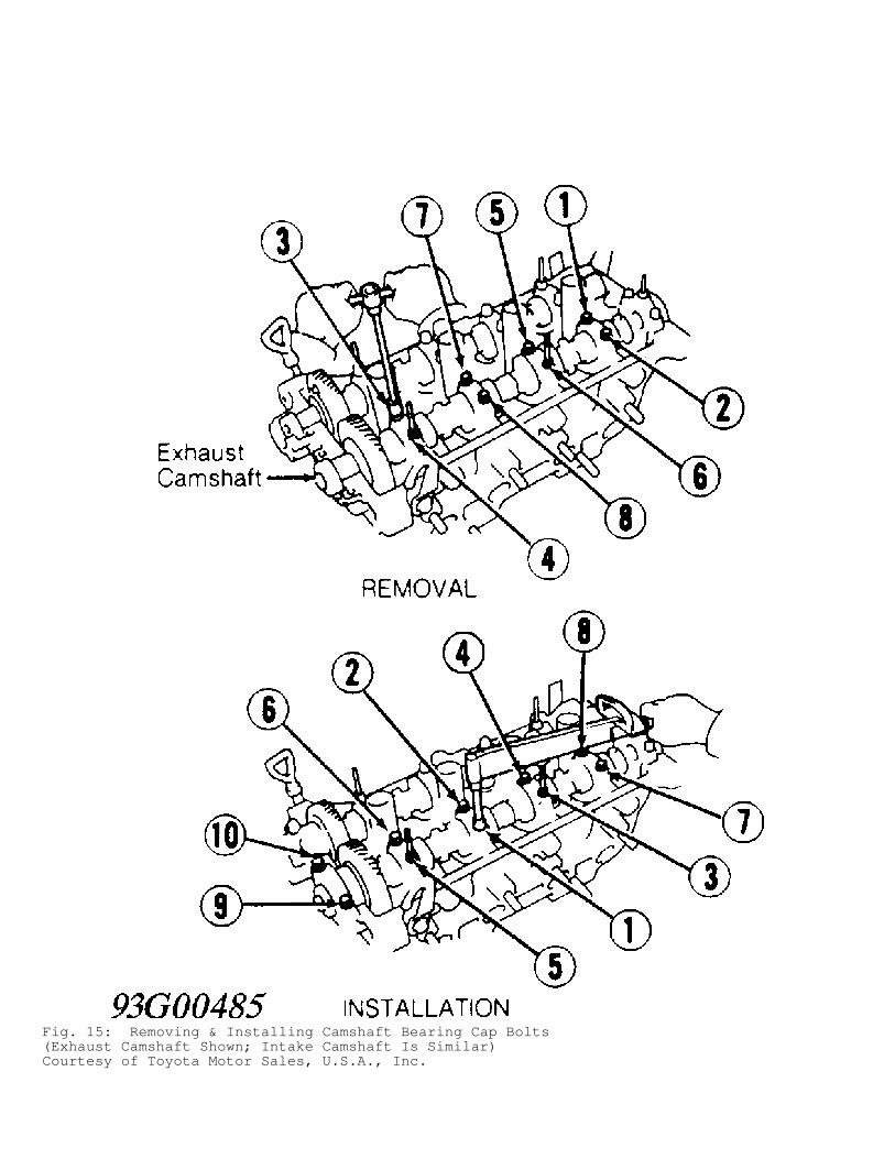
Fig. 15: Removing & Installing Camshaft Bearing Cap Bolts(Exhaust Camshaft Shown; Intake Camshaft Is Similar)Courtesy of Toyota Motor Sales, U.S.A., Inc.
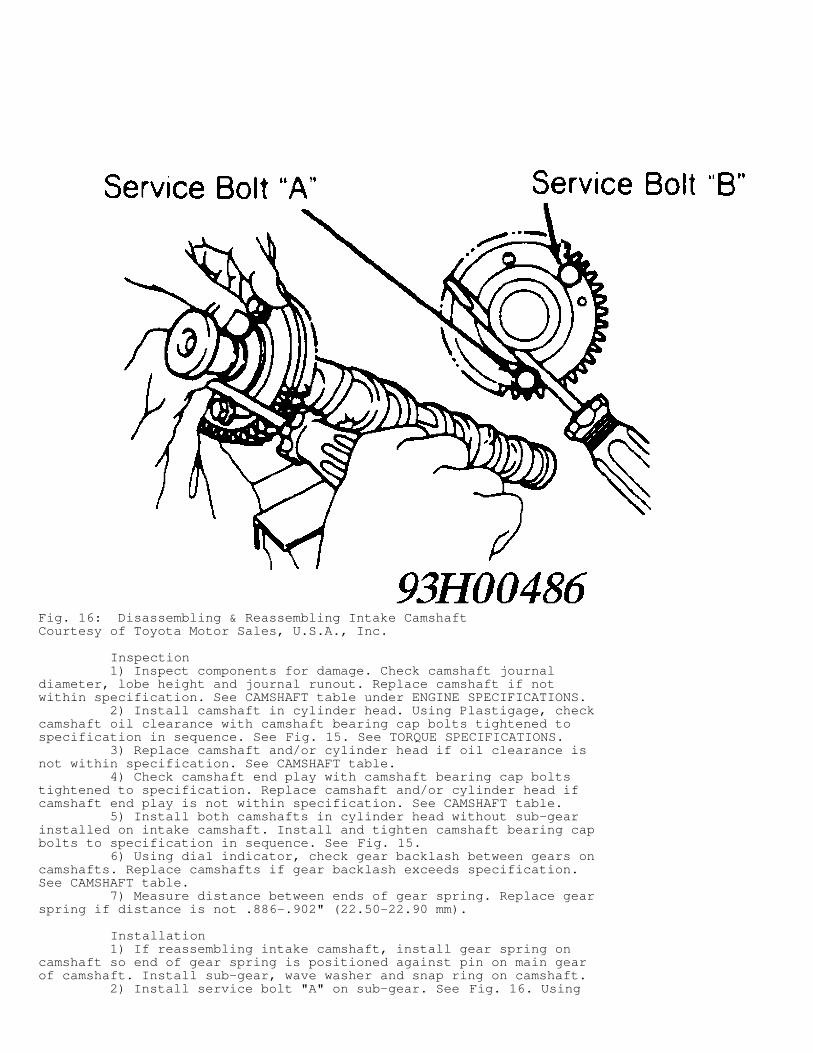
Fig. 16: Disassembling & Reassembling Intake CamshaftCourtesy of Toyota Motor Sales, U.S.A., Inc.
Inspection 1) Inspect components for damage. Check camshaft journaldiameter, lobe height and journal runout. Replace camshaft if notwithin specification. See CAMSHAFT table under ENGINE SPECIFICATIONS. 2) Install camshaft in cylinder head. Using Plastigage, checkcamshaft oil clearance with camshaft bearing cap bolts tightened tospecification in sequence. See Fig. 15. See TORQUE SPECIFICATIONS. 3) Replace camshaft and/or cylinder head if oil clearance isnot within specification. See CAMSHAFT table. 4) Check camshaft end play with camshaft bearing cap boltstightened to specification. Replace camshaft and/or cylinder head ifcamshaft end play is not within specification. See CAMSHAFT table. 5) Install both camshafts in cylinder head without sub-gearinstalled on intake camshaft. Install and tighten camshaft bearing capbolts to specification in sequence. See Fig. 15. 6) Using dial indicator, check gear backlash between gears oncamshafts. Replace camshafts if gear backlash exceeds specification.See CAMSHAFT table. 7) Measure distance between ends of gear spring. Replace gearspring if distance is not .886-.902" (22.50-22.90 mm).
Installation 1) If reassembling intake camshaft, install gear spring oncamshaft so end of gear spring is positioned against pin on main gearof camshaft. Install sub-gear, wave washer and snap ring on camshaft. 2) Install service bolt "A" on sub-gear. See Fig. 16. Using
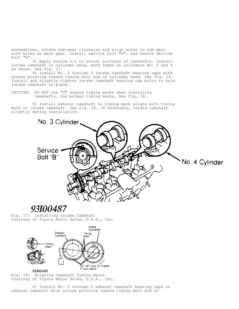
screwdriver, rotate sub-gear clockwise and align holes in sub-gearwith holes on main gear. Install service bolt "B", and remove servicebolt "A". 3) Apply engine oil to thrust surfaces of camshafts. Installintake camshaft in cylinder head, with lobes on cylinders No. 3 and 4as shown. See Fig. 17. 4) Install No. 2 through 5 intake camshaft bearing caps witharrows pointing toward timing belt end of cylinder head. See Fig. 14.Install and slightly tighten intake camshaft bearing cap bolts to holdintake camshaft in place.
CAUTION: DO NOT use "S" engine timing marks when installing camshafts. Use proper timing marks. See Fig. 18.
5) Install exhaust camshaft so timing mark aligns with timingmark on intake camshaft. See Fig. 18. If necessary, rotate camshaftslightly during installation.
Fig. 17: Installing Intake CamshaftCourtesy of Toyota Motor Sales, U.S.A., Inc.
Fig. 18: Aligning Camshaft Timing MarksCourtesy of Toyota Motor Sales, U.S.A., Inc.
6) Install No. 2 through 5 exhaust camshaft bearing caps onexhaust camshaft with arrows pointing toward timing belt end of
cylinder head. See Fig. 14. Install and slightly tighten exhaustcamshaft bearing cap bolts to hold camshaft in place. Remove servicebolt "B" from intake camshaft. 7) Apply sealant on No. 1 (front) intake camshaft bearingcap-to-cylinder head surface and install on cylinder head. Ensure noclearance exists between No. 1 (front) camshaft bearing cap andcylinder head surface. 8) Install and slightly tighten No. 1 (front) intake camshaftbearing cap bolts. Install housing plug. Tighten all intake camshaftbearing cap bolts to specification in sequence using several steps.See Fig. 15. See TORQUE SPECIFICATIONS. 9) Coat new oil seal lip of exhaust camshaft with grease.Install oil seal on front of exhaust camshaft until backside of oilseal contacts cylinder head. 10) Apply sealant on No. 1 (front) exhaust camshaft bearingcap-to-cylinder head surface and install on cylinder head. Ensure noclearance exists between No. 1 (front) camshaft bearing cap andcylinder head surface. 11) Install and slightly tighten No. 1 (front) exhaustcamshaft bearing cap bolts. Tighten all exhaust camshaft bearing capbolts to specification in sequence using several steps. See Fig. 15.See TORQUE SPECIFICATIONS.
CAUTION: Ensure service bolt "B" is removed from sub-gear on intake camshaft. Ensure timing marks are still aligned. See Fig. 18.
12) Check and adjust valve clearance. See VALVE CLEARANCEADJUSTMENT under ADJUSTMENTS. To install remaining components, reverseremoval procedure. 13) Apply sealant at indicated valve cover sealing areas oncylinder head. See Fig. 3. Using NEW gasket, install valve cover andsealing washers. Install and tighten nuts to specification. See TORQUESPECIFICATIONS. 14) Before installing distributor, install NEW "O" ring ondistributor. Coat "O" ring with engine oil. Rotate crankshaftclockwise so cylinder No. 1 is at TDC on compression stroke. CylinderNo. 1 is front cylinder at timing belt end of engine. 15) Ensure timing mark on crankshaft pulley aligns with "0"mark on timing belt cover. Ensure slot on exhaust camshaft is properlypositioned. See Fig. 10. 16) Position cut-out area on coupling with groove ondistributor housing. See Fig. 10. Install distributor. Position centerof flange on distributor with bolt hole on cylinder head. Install andtighten distributor hold-down bolts to specification. See TORQUESPECIFICATIONS. Adjust ignition timing.
CRANKSHAFT REAR OIL SEAL
Removal Remove transaxle, clutch assembly (if equipped) andflywheel/drive plate. Using a knife, cut off seal lip. Pry oil sealfrom rear oil seal retainer on cylinder block. Use care not to damagesealing surfaces.
Installation 1) Ensure all sealing surfaces are clean. Apply grease toseal lip of NEW oil seal. Using Oil Seal Installer (SST 09223-41020),install oil seal in rear oil seal retainer until oil seal is even withsurface of rear oil seal retainer. 2) Apply Loctite to flywheel/drive plate bolts. Install andtighten flywheel/drive plate bolts to specification in a crisscrosspattern. See TORQUE SPECIFICATIONS. To install remaining components,
reverse removal procedure.
WATER PUMP
Removal 1) Disconnect negative battery cable. Drain cooling system.Remove drive belt and alternator. Remove intake manifold brace,located on lower side of intake manifold. 2) Disconnect coolant hoses from coolant inlet pipe at rearof water pump. Remove bolt, coolant inlet pipe and "O" ring from rearof water pump. 3) Remove oil dipstick, alternator adjusting bar, dipsticktube and "O" ring. Remove bolts/nuts and water pump.
Installation 1) Ensure sealing surfaces are clean. Apply bead of sealantin groove on rear of water pump. Install water pump. Install andtighten bolts/nuts to specification. See TORQUE SPECIFICATIONS.
CAUTION: Install coolant inlet pipe evenly in water pump. DO NOT install coolant inlet pipe at an angle or use twisting motion during installation, as "O" ring will be damaged.
2) To install remaining components, reverse removal procedureusing NEW "O" rings. Coat all "O" rings with soapy water solutionbefore installing. Fill cooling system. Tighten all fasteners tospecification. See TORQUE SPECIFICATIONS.
OIL PAN
Removal 1) Disconnect negative battery cable. Raise and supportvehicle. Drain engine oil. 2) Disconnect oxygen sensor connector. Remove exhaust pipe-to-cylinder block support bracket bolts. Remove nuts and separateexhaust pipe from exhaust manifold. 3) If necessary to access oil pan bolts, remove A/Ccompressor with hoses attached and secure aside (if equipped). RemoveA/C compressor mounting bracket (if equipped). Remove oil dipstick.Remove bolts/nuts and oil pan.
Installation 1) To install, ensure sealing surfaces are clean. Apply beadof sealant on inside of bolt/nut holes and at center of oil pansealing surface, between bolt/nut holes. 2) Install oil pan. Install and tighten bolts/nuts tospecification. See TORQUE SPECIFICATIONS. To install remainingcomponents, reverse removal procedure. Use NEW nuts when installingexhaust pipe on exhaust manifold. Fill crankcase with oil.
OVERHAUL
CYLINDER HEAD
Cylinder Head 1) Inspect cylinder head warpage at cylinder block andmanifold surfaces. Replace cylinder head if warpage exceedsspecification. See CYLINDER HEAD table under ENGINE SPECIFICATIONS. 2) Install camshaft in cylinder head. Using Plastigage, checkcamshaft oil clearance with camshaft bearing caps installed and boltstightened to specification in sequence. See Fig. 15. See TORQUESPECIFICATIONS.
3) Replace camshaft and/or cylinder head if oil clearance isnot within specification. See CAMSHAFT table under ENGINESPECIFICATIONS. 4) Check camshaft end play with camshaft bearing cap boltstightened to specification. Replace camshaft and/or cylinder head ifcamshaft end play is not within specification. See CAMSHAFT table. 5) Install both camshafts in cylinder head without sub-gearinstalled on intake camshaft. Install and tighten camshaft bearing capbolts to specification in sequence. See Fig. 15. See TORQUESPECIFICATIONS. 6) Using dial indicator, check gear backlash between gears oncamshafts. Replace camshafts if gear backlash exceeds specification.See CAMSHAFT table. 7) Ensure valve lifter bore diameter is within specification.See VALVE LIFTERS table under ENGINE SPECIFICATIONS. 8) If installing spark plug tubes in NEW cylinder head, applyThree Bond Sealant (08833-00070) on spark plug tube surface ofcylinder head. 9) Using a press, install spark plug tube in cylinder headuntil distance from top surface of spark plug tube to camshaft bearingcap surface on cylinder head is 2.185-2.228" (55.50-56.60 mm).
Valve Springs Ensure valve spring free length, pressure and out-of-squareare within specification. See VALVES & VALVE SPRINGS table underENGINE SPECIFICATIONS.
CAUTION: Intake valve stem oil seal is Brown, and exhaust valve stem oil seal is Black. Ensure valve stem oil seal is installed in proper location.
Valve Stem Oil Seals Intake valve stem oil seal is Brown, and exhaust valve stemoil seal is Black. Lubricate valve stem oil seal with engine oil.Install valve stem oil seal using suitable diameter socket.
Valve Guides 1) Ensure valve guide inside diameter is withinspecification. See CYLINDER HEAD table under ENGINE SPECIFICATIONS.Replace valve guide if inside diameter exceeds specification. 2) To replace valve guide, use Valve Guide Remover/Installer(SST 09201-70010). Using hammer and valve guide remover/installer,drive valve guide from camshaft side of cylinder head. 3) Measure cylinder head valve guide bore inside diameter. Ifbore inside diameter is .4331-.4341" (11.000-11.027 mm), use standardvalve guide. If bore inside diameter is .4350-.4361" (11.050-11.077mm), use oversize valve guide. 4) If bore inside diameter exceeds .4341" (11.027 mm),machine valve guide bore to .4350-.4361" (11.050-11.077 mm) foroversize valve guide. If bore inside diameter exceeds .4361" (11.077mm), replace cylinder head.
CAUTION: Exhaust valve guide is 1.59" (40.5 mm) long, and intake valve guide is 1.52" (38.5 mm) long. Ensure proper length valve guide is installed.
5) To install valve guide, use hammer and valve guideremover/installer. Drive valve guide in from camshaft side of cylinderhead until valve guide installed height is .500-.516" (12.70-13.10mm). See Fig. 19. 6) Using .236" (6.00 mm) reamer, ream valve guide to obtainspecified valve stem-to-guide oil clearance. See CYLINDER HEAD table.
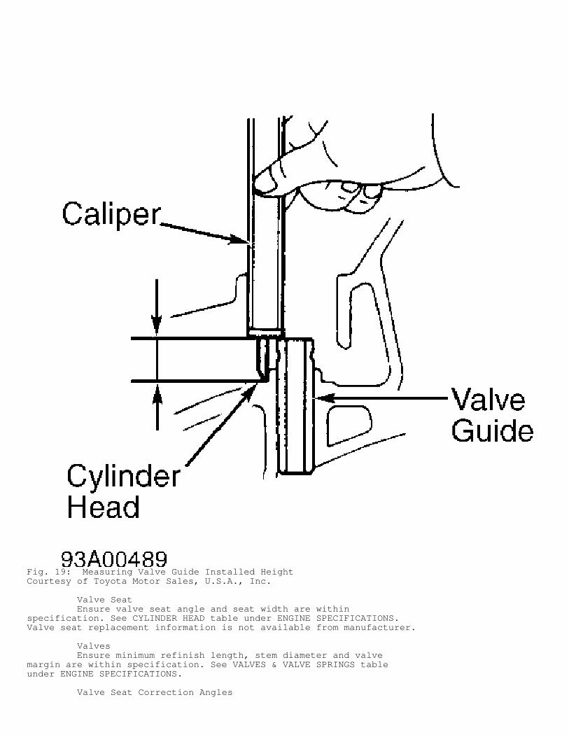
Fig. 19: Measuring Valve Guide Installed HeightCourtesy of Toyota Motor Sales, U.S.A., Inc.
Valve Seat Ensure valve seat angle and seat width are withinspecification. See CYLINDER HEAD table under ENGINE SPECIFICATIONS.Valve seat replacement information is not available from manufacturer.
Valves Ensure minimum refinish length, stem diameter and valvemargin are within specification. See VALVES & VALVE SPRINGS tableunder ENGINE SPECIFICATIONS.
Valve Seat Correction Angles

Use 30-degree and 45-degree stones to lower valve seatcontact area. Use 75-degree and 45-degree stones to raise exhaustvalve seat contact area. Use 75-degree, 60-degree and 45-degree stonesto raise intake valve seat contact area.
VALVE TRAIN
Valve Lifters Ensure valve lifter diameter, bore diameter and oil clearanceare within specification. See VALVE LIFTERS table under ENGINESPECIFICATIONS.
CYLINDER BLOCK ASSEMBLY
Piston & Rod Assembly 1) Ensure connecting rod and connecting rod cap are markedwith matching cylinder number for reassembly reference. Beforedisassembling piston and connecting rod, try to move piston back andforth on piston pin. Replace piston and piston pin if any movement isfelt. 2) When removing piston from connecting rod, press piston pinfrom piston. Ensure connecting rod bend, twist and crankpin borediameter are within specification. See CONNECTING RODS table underENGINE SPECIFICATIONS.
NOTE: Crankpin bore diameter is determined by size mark stamped on connecting rod cap. See Fig. 23.
3) To reassemble, install piston on connecting rod so frontmark (arrow) on top of piston aligns with front mark (protrusion) onconnecting rod. See Fig. 20. Coat piston pin and piston pin holes inpiston with oil. Press piston pin into piston.
CAUTION: With connecting rod centered in piston, ensure same distance exists between end of piston pin and piston. If distance varies, relocate piston pin.
Fig. 20: Aligning Connecting Rod & Piston Front MarksCourtesy of Toyota Motor Sales, U.S.A., Inc.
Fitting Pistons 1) Different piston and cylinder bore sizes are used. Piston
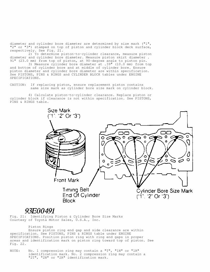
diameter and cylinder bore diameter are determined by size mark ("1","2" or "3") stamped on top of piston and cylinder block deck surface,respectively. See Fig. 21. 2) To determine piston-to-cylinder clearance, measure pistondiameter and cylinder bore diameter. Measure piston skirt diameter .91" (23.0 mm) from top of piston, at 90-degree angle to piston pin. 3) Measure cylinder bore diameter at .39" (10.0 mm) from topand bottom of cylinder bore and at middle of cylinder bore. Ensurepiston diameter and cylinder bore diameter are within specification.See PISTONS, PINS & RINGS and CYLINDER BLOCK tables under ENGINESPECIFICATIONS.
CAUTION: If replacing piston, ensure replacement piston contains same size mark as cylinder bore size mark on cylinder block.
4) Calculate piston-to-cylinder clearance. Replace piston orcylinder block if clearance is not within specification. See PISTONS,PINS & RINGS table.
Fig. 21: Identifying Piston & Cylinder Bore Size MarksCourtesy of Toyota Motor Sales, U.S.A., Inc.
Piston Rings Ensure piston ring end gap and side clearance are withinspecification. See PISTONS, PINS & RINGS table under ENGINESPECIFICATIONS. Position piston ring with ring end gaps in properareas and identification mark on piston ring toward top of piston. SeeFig. 22.
NOTE: No. 1 compression ring may contain a "T", "1N" or "1R" identification mark. No. 2 compression ring may contain a "2T", "2N" or "2R" identification mark.
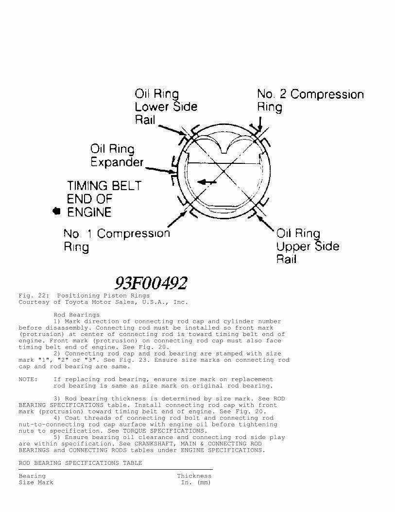
Fig. 22: Positioning Piston RingsCourtesy of Toyota Motor Sales, U.S.A., Inc.
Rod Bearings 1) Mark direction of connecting rod cap and cylinder numberbefore disassembly. Connecting rod must be installed so front mark(protrusion) at center of connecting rod is toward timing belt end ofengine. Front mark (protrusion) on connecting rod cap must also facetiming belt end of engine. See Fig. 20. 2) Connecting rod cap and rod bearing are stamped with sizemark "1", "2" or "3". See Fig. 23. Ensure size marks on connecting rodcap and rod bearing are same.
NOTE: If replacing rod bearing, ensure size mark on replacement rod bearing is same as size mark on original rod bearing.
3) Rod bearing thickness is determined by size mark. See RODBEARING SPECIFICATIONS table. Install connecting rod cap with frontmark (protrusion) toward timing belt end of engine. See Fig. 20. 4) Coat threads of connecting rod bolt and connecting rodnut-to-connecting rod cap surface with engine oil before tighteningnuts to specification. See TORQUE SPECIFICATIONS. 5) Ensure bearing oil clearance and connecting rod side playare within specification. See CRANKSHAFT, MAIN & CONNECTING RODBEARINGS and CONNECTING RODS tables under ENGINE SPECIFICATIONS.
ROD BEARING SPECIFICATIONS TABLE���������������������������������������������������������������������������������������������������Bearing ThicknessSize Mark In. (mm)
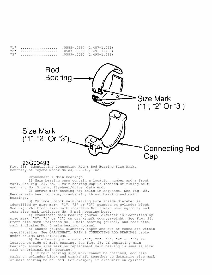
"1" .................. .0585-.0587 (1.487-1.491)"2" .................. .0587-.0589 (1.491-1.495)"3" .................. .0589-.0590 (1.495-1.499)���������������������������������������������������������������������������������������������������
Fig. 23: Identifying Connecting Rod & Rod Bearing Size MarksCourtesy of Toyota Motor Sales, U.S.A., Inc.
Crankshaft & Main Bearings 1) Main bearing caps contain a location number and a frontmark. See Fig. 24. No. 1 main bearing cap is located at timing beltend, and No. 5 is at flywheel/drive plate end. 2) Remove main bearing cap bolts in sequence. See Fig. 25.Remove main bearing caps, crankshaft, thrust bearing and mainbearings. 3) Cylinder block main bearing bore inside diameter isidentified by size mark ("1", "2" or "3") stamped on cylinder block.See Fig. 26. Front size mark indicates No. 1 main bearing bore, andrear size mark indicates No. 5 main bearing bore. 4) Crankshaft main bearing journal diameter is identified bysize mark ("0", "1" or "2") on crankshaft counterweight. See Fig. 26.Front size mark indicates No. 1 main bearing journal, and rear sizemark indicates No. 5 main bearing journal. 5) Ensure journal diameter, taper and out-of-round are withinspecification. See CRANKSHAFT, MAIN & CONNECTING ROD BEARINGS tableunder ENGINE SPECIFICATIONS. 6) Main bearing size mark ("1", "2", "3", "4" or "5") islocated on side of main bearing. See Fig. 26. If replacing mainbearing, ensure size mark on replacement main bearing is same as sizemark on original main bearing. 7) If main bearing size mark cannot be obtained, add sizemarks on cylinder block and crankshaft together to determine size markof main bearing to be used. For example, if size mark on cylinder
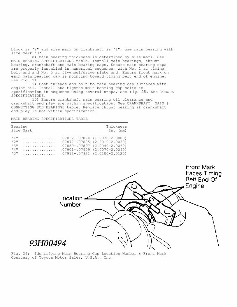
block is "2" and size mark on crankshaft is "1", use main bearing withsize mark "3". 8) Main bearing thickness is determined by size mark. SeeMAIN BEARING SPECIFICATIONS table. Install main bearings, thrustbearing, crankshaft and main bearing caps. Ensure main bearing capsare properly installed in numerical sequence, with No. 1 at timingbelt end and No. 5 at flywheel/drive plate end. Ensure front mark oneach main bearing cap is pointing toward timing belt end of engine.See Fig. 24. 9) Coat threads and bolt-to-main bearing cap surfaces withengine oil. Install and tighten main bearing cap bolts tospecification in sequence using several steps. See Fig. 25. See TORQUESPECIFICATIONS. 10) Ensure crankshaft main bearing oil clearance andcrankshaft end play are within specification. See CRANKSHAFT, MAIN &CONNECTING ROD BEARINGS table. Replace thrust bearing if crankshaftend play is not within specification.
MAIN BEARING SPECIFICATIONS TABLE���������������������������������������������������������������������������������������������������Bearing ThicknessSize Mark In. (mm)
"1" .............. .07862-.07874 (1.9970-2.0000)"2" .............. .07877-.07885 (2.0010-2.0030)"3" .............. .07889-.07897 (2.0040-2.0060)"4" .............. .07901-.07909 (2.0070-2.0090)"5" .............. .07913-.07921 (2.0100-2.0120)���������������������������������������������������������������������������������������������������
Fig. 24: Identifying Main Bearing Cap Location Number & Front MarkCourtesy of Toyota Motor Sales, U.S.A., Inc.
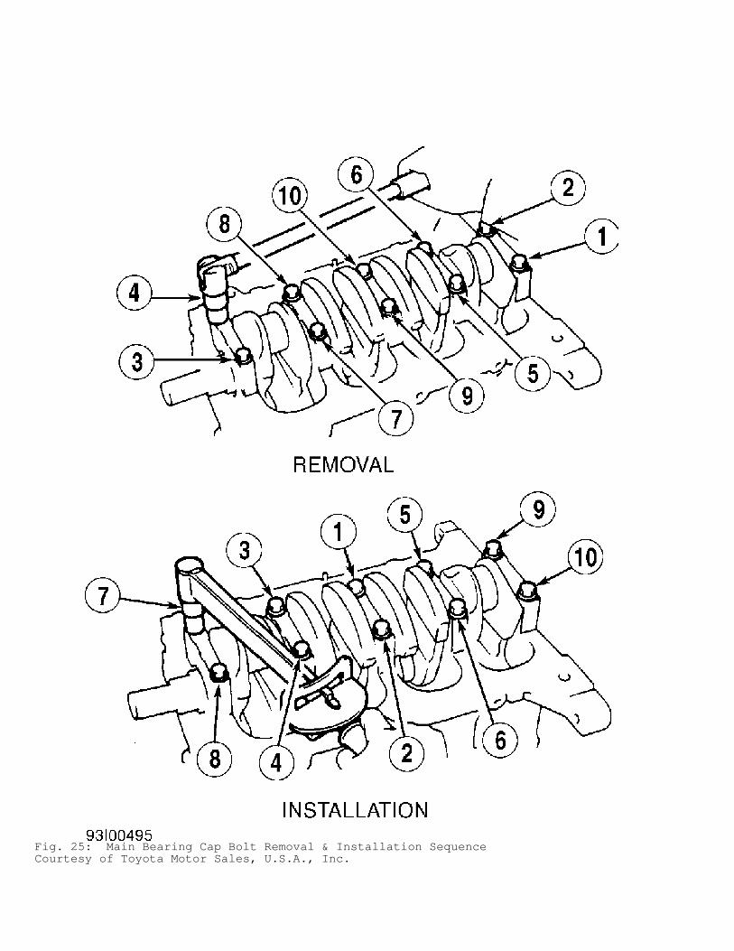
Fig. 25: Main Bearing Cap Bolt Removal & Installation SequenceCourtesy of Toyota Motor Sales, U.S.A., Inc.
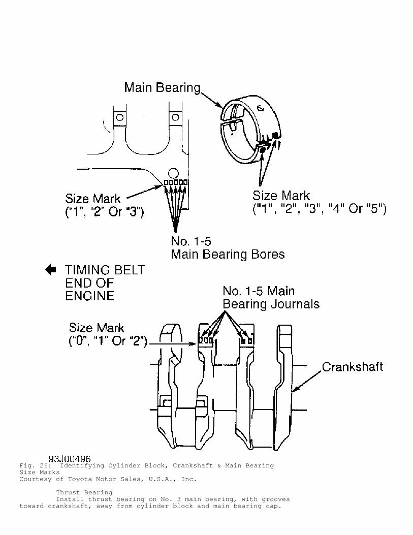
Fig. 26: Identifying Cylinder Block, Crankshaft & Main BearingSize MarksCourtesy of Toyota Motor Sales, U.S.A., Inc.
Thrust Bearing Install thrust bearing on No. 3 main bearing, with groovestoward crankshaft, away from cylinder block and main bearing cap.
Replace thrust bearing if crankshaft end play is not withinspecification. See CRANKSHAFT, MAIN & CONNECTING ROD BEARINGS tableunder ENGINE SPECIFICATIONS.
Cylinder Block 1) Inspect cylinder block deck surface warpage. Replacecylinder block if deck warpage exceeds specification. See CYLINDERBLOCK table under ENGINE SPECIFICATIONS. 2) Different cylinder bore sizes are used. Cylinder bore sizeis identified by size mark ("1", "2" or "3") on cylinder block decksurface. See Fig. 21. Measure cylinder bore diameter at .39" (10.0 mm)from top and bottom of cylinder bore and at middle of cylinder bore. 3) Ensure cylinder bore diameter is within specification. SeeCYLINDER BLOCK table. Replace cylinder block if cylinder bore exceedsspecification. 4) Install main bearing caps in numerical sequence, with No.1 at timing belt end and No. 5 at flywheel/drive plate end. Ensurefront mark on each main bearing cap points toward timing belt end ofengine. See Fig. 24. 5) Install and tighten main bearing cap bolts tospecification in sequence using several steps. See Fig. 25. See TORQUESPECIFICATIONS. Ensure main bearing bore inside diameter is withinspecification. See CYLINDER BLOCK table.
NOTE: Main bearing bore inside diameter is identified by main bearing bore size mark ("1", "2" or "3") stamped on cylinder block. See Fig. 26.
ENGINE OILING
ENGINE LUBRICATION SYSTEM
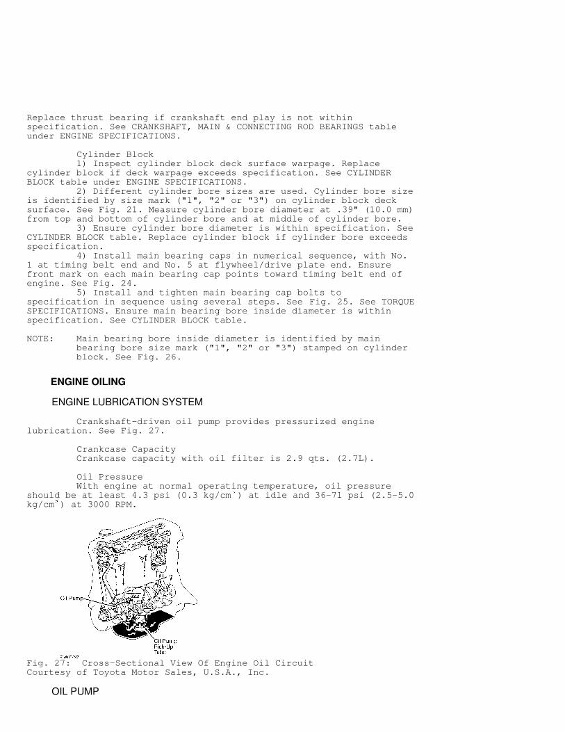
Crankshaft-driven oil pump provides pressurized enginelubrication. See Fig. 27.
Crankcase Capacity Crankcase capacity with oil filter is 2.9 qts. (2.7L).
Oil Pressure With engine at normal operating temperature, oil pressureshould be at least 4.3 psi (0.3 kg/cm ) at idle and 36-71 psi (2.5-5.0kg/cm ) at 3000 RPM.
Fig. 27: Cross-Sectional View Of Engine Oil CircuitCourtesy of Toyota Motor Sales, U.S.A., Inc.
OIL PUMP
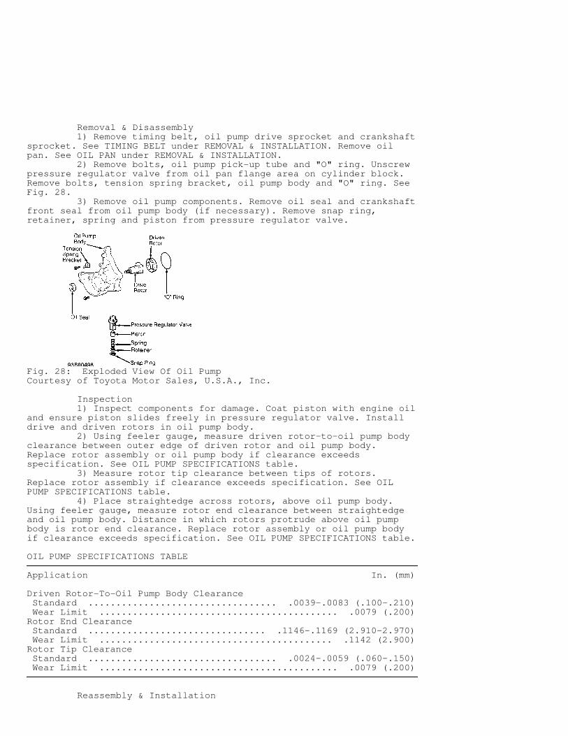
Removal & Disassembly 1) Remove timing belt, oil pump drive sprocket and crankshaftsprocket. See TIMING BELT under REMOVAL & INSTALLATION. Remove oilpan. See OIL PAN under REMOVAL & INSTALLATION. 2) Remove bolts, oil pump pick-up tube and "O" ring. Unscrewpressure regulator valve from oil pan flange area on cylinder block.Remove bolts, tension spring bracket, oil pump body and "O" ring. SeeFig. 28. 3) Remove oil pump components. Remove oil seal and crankshaftfront seal from oil pump body (if necessary). Remove snap ring,retainer, spring and piston from pressure regulator valve.
Fig. 28: Exploded View Of Oil PumpCourtesy of Toyota Motor Sales, U.S.A., Inc.
Inspection 1) Inspect components for damage. Coat piston with engine oiland ensure piston slides freely in pressure regulator valve. Installdrive and driven rotors in oil pump body. 2) Using feeler gauge, measure driven rotor-to-oil pump bodyclearance between outer edge of driven rotor and oil pump body.Replace rotor assembly or oil pump body if clearance exceedsspecification. See OIL PUMP SPECIFICATIONS table. 3) Measure rotor tip clearance between tips of rotors.Replace rotor assembly if clearance exceeds specification. See OILPUMP SPECIFICATIONS table. 4) Place straightedge across rotors, above oil pump body.Using feeler gauge, measure rotor end clearance between straightedgeand oil pump body. Distance in which rotors protrude above oil pumpbody is rotor end clearance. Replace rotor assembly or oil pump bodyif clearance exceeds specification. See OIL PUMP SPECIFICATIONS table.
OIL PUMP SPECIFICATIONS TABLE�������������������������������������������������������������������������������������������������������������������������������������������Application In. (mm)
Driven Rotor-To-Oil Pump Body Clearance Standard .................................. .0039-.0083 (.100-.210) Wear Limit ........................................... .0079 (.200)Rotor End Clearance Standard ................................ .1146-.1169 (2.910-2.970) Wear Limit .......................................... .1142 (2.900)Rotor Tip Clearance Standard .................................. .0024-.0059 (.060-.150) Wear Limit ........................................... .0079 (.200)�������������������������������������������������������������������������������������������������������������������������������������������
Reassembly & Installation
1) To reassemble, reverse disassembly procedure. Ensurereference marks (dot area) on rotors face toward outside of oil pumpbody (away from cylinder block surface). 2) Using Seal Installer (SST 09309-37010), install NEWcrankshaft front seal (if removed) until seal surface is even with oilpump body. Coat seal lip with grease. 3) Install NEW oil seal (if removed) in oil pump body usingsuitable size socket until seal surface is even with oil pump body.Coat seal lip with grease. 4) To install, apply sealant on rear of oil pump. Install NEW"O" ring in groove on oil pump body. Install oil pump on cylinderblock. Install and tighten oil pump bolts and pressure regulator valveto specification. See TORQUE SPECIFICATIONS. To install remainingcomponents, reverse removal procedure.
TORQUE SPECIFICATIONS
TORQUE SPECIFICATIONS TABLE�����������������������������������������������������������������������������������������������������������������������Application Ft. Lbs. (N.m)
Accessory Drive Belt Pulley Bolt ................. 14 (19)A/C Compressor Bolt .............................. 18 (24)A/C Compressor Mounting Bracket Bolt ............. 20 (27)A/C Idler Pulley Bolt 12-mm Bolt ...................................... 20 (27) 14-mm Bolt ...................................... 27 (37)Axle Shaft Nut ................................. 159 (216)Ball Joint-To-Lower Control Arm Bolt/Nut ......... 59 (80)Camshaft Sprocket Bolt ........................... 37 (51)Connecting Rod Nut ............................... 29 (39)Coolant Housing Bolt/Nut ......................... 13 (18)Crankshaft Pulley Bolt ......................... 112 (152)Cylinder Head Bolt (1) Step 1 .......................................... 33 (45) Step 2 ............................ Additional 90 DegreesDelivery Pipe Bolt ............................... 14 (19)Distributor Hold-Down Bolt ....................... 13 (18)EGR Pipe Nut ............................................. 22 (30) Union Nut ....................................... 29 (39)EGR Temperature Sensor ........................... 15 (20)EGR Valve Nut .................................... 13 (18)Engine Mount Left (Transaxle Side) Bracket-To-Mount Insulator Bolt ................. 35 (47) Bracket-To-Transaxle Bolt ....................... 47 (64) Rear (Firewall Side) Bracket-To-Transaxle Bolt ....................... 35 (47) Through-Bolt .................................... 47 (64) Right (Timing Belt Side) Mount-To-Cylinder Block Bolt/Nut ................ 47 (64) Through-Bolt .................................... 54 (73)Exhaust Manifold Nut ............................. 35 (47)Exhaust Pipe Support Bracket Bolt ................ 14 (19)Exhaust Pipe-To-Exhaust Manifold Nut ............. 46 (62)Flywheel/Drive Plate Bolt ........................ 65 (88)Fuel Line Banjo Bolt ............................. 22 (30)Idler Pulley Bolt No. 1 Idler Pulley .............................. 13 (18) No. 2 Idler Pulley .............................. 20 (27)Intake Manifold Bolt/Nut ......................... 14 (19)
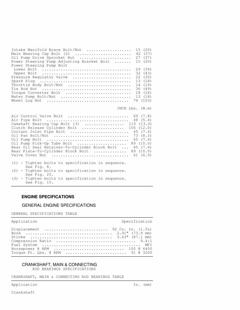
Intake Manifold Brace Bolt/Nut ................... 15 (20)Main Bearing Cap Bolt (2) ........................ 42 (57)Oil Pump Drive Sprocket Nut ...................... 27 (37)Power Steering Pump Adjusting Bracket Bolt ....... 15 (20)Power Steering Pump Bolt Lower Bolt ...................................... 29 (39) Upper Bolt ...................................... 32 (43)Pressure Regulator Valve ......................... 22 (30)Spark Plug ....................................... 13 (18)Throttle Body Bolt/Nut ........................... 14 (19)Tie Rod Nut ...................................... 36 (49)Torque Converter Bolt ............................ 18 (24)Water Pump Bolt/Nut .............................. 13 (18)Wheel Lug Nut ................................... 76 (103)
INCH Lbs. (N.m)
Air Control Valve Bolt .......................... 69 (7.8)Air Pipe Bolt ................................... 48 (5.4)Camshaft Bearing Cap Bolt (3) ................. 115 (13.0)Clutch Release Cylinder Bolt .................. 106 (12.0)Coolant Inlet Pipe Bolt ......................... 65 (7.4)Oil Pan Bolt/Nut ................................ 73 (8.3)Oil Pump Bolt ................................... 65 (7.4)Oil Pump Pick-Up Tube Bolt ..................... 89 (10.0)Rear Oil Seal Retainer-To-Cylinder Block Bolt ... 65 (7.4)Rear Plate-To-Cylinder Block Bolt .............. 89 (10.0)Valve Cover Nut ................................. 61 (6.9)
(1) - Tighten bolts to specification in sequence. See Fig. 8.(2) - Tighten bolts to specification in sequence. See Fig. 25.(3) - Tighten bolts to specification in sequence. See Fig. 15.�����������������������������������������������������������������������������������������������������������������������
ENGINE SPECIFICATIONS
GENERAL ENGINE SPECIFICATIONS
GENERAL SPECIFICATIONS TABLE�����������������������������������������������������������������������������������������������������������������������Application Specification
Displacement ........................... 92 Cu. In. (1.5L)Bore ..................................... 2.91" (73.9 mm)Stroke ................................... 3.43" (87.1 mm)Compression Ratio .................................. 9.4:1Fuel System .......................................... MFIHorsepower @ RPM .............................. 100 @ 6400Torque Ft. Lbs. @ RPM .......................... 91 @ 3200�����������������������������������������������������������������������������������������������������������������������
CRANKSHAFT, MAIN & CONNECTING ROD BEARINGS SPECIFICATIONS
CRANKSHAFT, MAIN & CONNECTING ROD BEARINGS TABLE�����������������������������������������������������������������������������������������������������������������������Application In. (mm)
Crankshaft
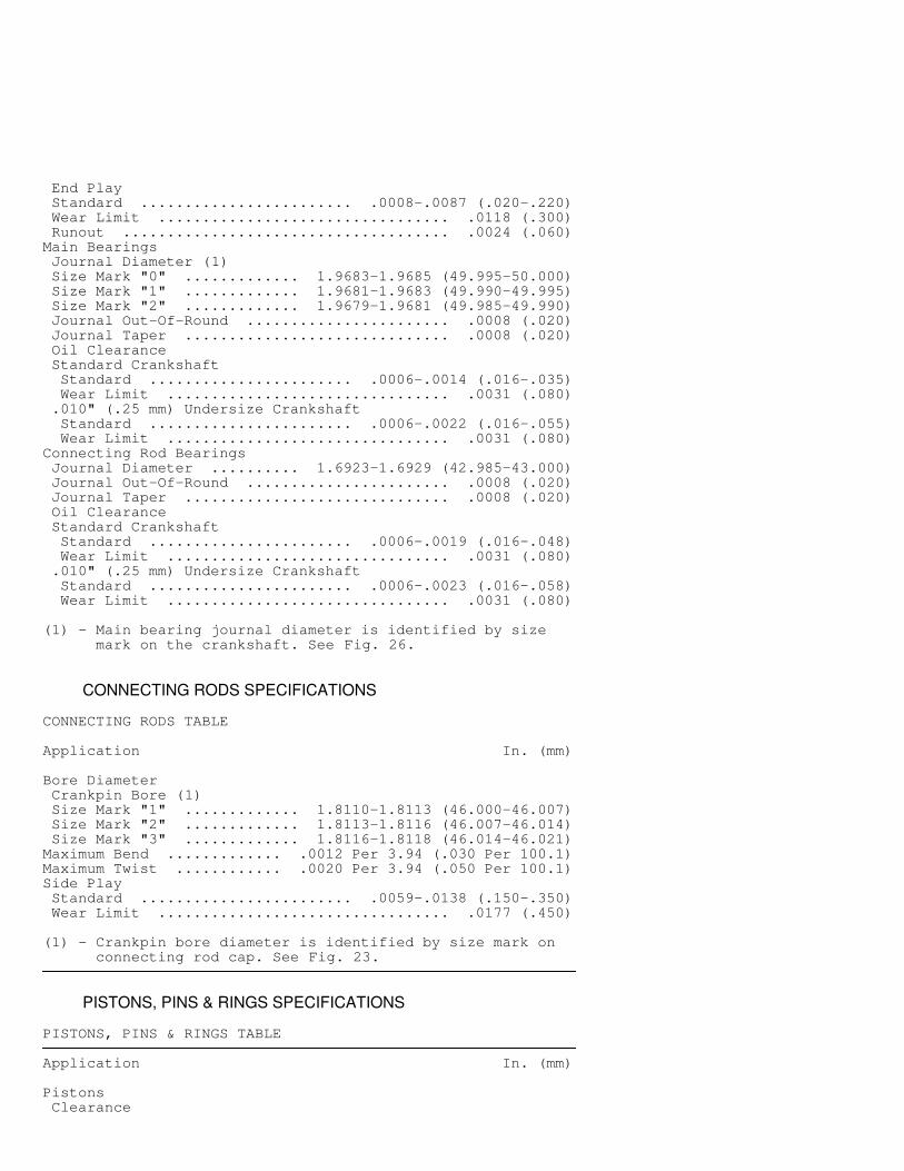
End Play Standard ........................ .0008-.0087 (.020-.220) Wear Limit ................................. .0118 (.300) Runout ..................................... .0024 (.060)Main Bearings Journal Diameter (1) Size Mark "0" ............. 1.9683-1.9685 (49.995-50.000) Size Mark "1" ............. 1.9681-1.9683 (49.990-49.995) Size Mark "2" ............. 1.9679-1.9681 (49.985-49.990) Journal Out-Of-Round ....................... .0008 (.020) Journal Taper .............................. .0008 (.020) Oil Clearance Standard Crankshaft Standard ....................... .0006-.0014 (.016-.035) Wear Limit ................................ .0031 (.080) .010" (.25 mm) Undersize Crankshaft Standard ....................... .0006-.0022 (.016-.055) Wear Limit ................................ .0031 (.080)Connecting Rod Bearings Journal Diameter .......... 1.6923-1.6929 (42.985-43.000) Journal Out-Of-Round ....................... .0008 (.020) Journal Taper .............................. .0008 (.020) Oil Clearance Standard Crankshaft Standard ....................... .0006-.0019 (.016-.048) Wear Limit ................................ .0031 (.080) .010" (.25 mm) Undersize Crankshaft Standard ....................... .0006-.0023 (.016-.058) Wear Limit ................................ .0031 (.080)
(1) - Main bearing journal diameter is identified by size mark on the crankshaft. See Fig. 26.�����������������������������������������������������������������������������������������������������������������������
CONNECTING RODS SPECIFICATIONS
CONNECTING RODS TABLE�����������������������������������������������������������������������������������������������������������������������Application In. (mm)
Bore Diameter Crankpin Bore (1) Size Mark "1" ............. 1.8110-1.8113 (46.000-46.007) Size Mark "2" ............. 1.8113-1.8116 (46.007-46.014) Size Mark "3" ............. 1.8116-1.8118 (46.014-46.021)Maximum Bend ............. .0012 Per 3.94 (.030 Per 100.1)Maximum Twist ............ .0020 Per 3.94 (.050 Per 100.1)Side Play Standard ........................ .0059-.0138 (.150-.350) Wear Limit ................................. .0177 (.450)
(1) - Crankpin bore diameter is identified by size mark on connecting rod cap. See Fig. 23.�����������������������������������������������������������������������������������������������������������������������
PISTONS, PINS & RINGS SPECIFICATIONS
PISTONS, PINS & RINGS TABLE�����������������������������������������������������������������������������������������������������������������������Application In. (mm)
Pistons Clearance
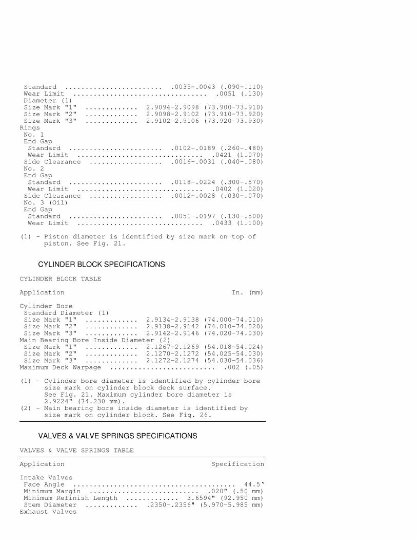
Standard ........................ .0035-.0043 (.090-.110) Wear Limit ................................. .0051 (.130) Diameter (1) Size Mark "1" ............. 2.9094-2.9098 (73.900-73.910) Size Mark "2" ............. 2.9098-2.9102 (73.910-73.920) Size Mark "3" ............. 2.9102-2.9106 (73.920-73.930)Rings No. 1 End Gap Standard ....................... .0102-.0189 (.260-.480) Wear Limit ............................... .0421 (1.070) Side Clearance .................. .0016-.0031 (.040-.080) No. 2 End Gap Standard ....................... .0118-.0224 (.300-.570) Wear Limit ............................... .0402 (1.020) Side Clearance .................. .0012-.0028 (.030-.070) No. 3 (Oil) End Gap Standard ....................... .0051-.0197 (.130-.500) Wear Limit ............................... .0433 (1.100)
(1) - Piston diameter is identified by size mark on top of piston. See Fig. 21.�����������������������������������������������������������������������������������������������������������������������
CYLINDER BLOCK SPECIFICATIONS
CYLINDER BLOCK TABLE�����������������������������������������������������������������������������������������������������������������������Application In. (mm)
Cylinder Bore Standard Diameter (1) Size Mark "1" ............. 2.9134-2.9138 (74.000-74.010) Size Mark "2" ............. 2.9138-2.9142 (74.010-74.020) Size Mark "3" ............. 2.9142-2.9146 (74.020-74.030)Main Bearing Bore Inside Diameter (2) Size Mark "1" ............. 2.1267-2.1269 (54.018-54.024) Size Mark "2" ............. 2.1270-2.1272 (54.025-54.030) Size Mark "3" ............. 2.1272-2.1274 (54.030-54.036)Maximum Deck Warpage .......................... .002 (.05)
(1) - Cylinder bore diameter is identified by cylinder bore size mark on cylinder block deck surface. See Fig. 21. Maximum cylinder bore diameter is 2.9224" (74.230 mm).(2) - Main bearing bore inside diameter is identified by size mark on cylinder block. See Fig. 26.�����������������������������������������������������������������������������������������������������������������������
VALVES & VALVE SPRINGS SPECIFICATIONS
VALVES & VALVE SPRINGS TABLE�����������������������������������������������������������������������������������������������������������������������Application Specification
Intake Valves Face Angle ........................................ 44.5 � Minimum Margin ........................... .020" (.50 mm) Minimum Refinish Length ............. 3.6594" (92.950 mm) Stem Diameter ............. .2350-.2356" (5.970-5.985 mm)Exhaust Valves
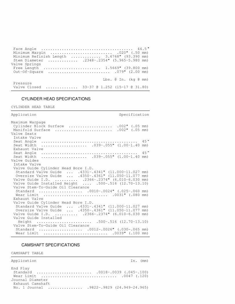
Face Angle ........................................ 44.5 � Minimum Margin ........................... .020" (.50 mm) Minimum Refinish Length ............. 3.6768" (93.390 mm) Stem Diameter ............. .2348-.2354" (5.965-5.980 mm)Valve Springs Free Length ......................... 1.5669" (39.800 mm) Out-Of-Square ........................... .079" (2.00 mm)
Lbs. @ In. (kg @ mm) Pressure Valve Closed .............. 33-37 @ 1.252 (15-17 @ 31.80)�����������������������������������������������������������������������������������������������������������������������
CYLINDER HEAD SPECIFICATIONS
CYLINDER HEAD TABLE�����������������������������������������������������������������������������������������������������������������������Application Specification
Maximum Warpage Cylinder Block Surface ................... .002" (.05 mm) Manifold Surface ......................... .002" (.05 mm)Valve Seats Intake Valve Seat Angle .......................................... 45 � Seat Width .................... .039-.055" (1.00-1.40 mm) Exhaust Valve Seat Angle .......................................... 45 � Seat Width .................... .039-.055" (1.00-1.40 mm)Valve Guides Intake Valve Valve Guide Cylinder Head Bore I.D. Standard Valve Guide ... .4331-.4341" (11.000-11.027 mm) Oversize Valve Guide ... .4350-.4361" (11.050-11.077 mm) Valve Guide I.D. .......... .2366-.2374" (6.010-6.030 mm) Valve Guide Installed Height .... .500-.516 (12.70-13.10) Valve Stem-To-Guide Oil Clearance Standard ................... .0010-.0024" (.025-.060 mm) Wear Limit ............................ .0031" (.080 mm) Exhaust Valve Valve Guide Cylinder Head Bore I.D. Standard Valve Guide ... .4331-.4341" (11.000-11.027 mm) Oversize Valve Guide ... .4350-.4361" (11.050-11.077 mm) Valve Guide I.D. .......... .2366-.2374" (6.010-6.030 mm) Valve Guide Installed Height ........................ .500-.516 (12.70-13.10) Valve Stem-To-Guide Oil Clearance Standard ................... .0012-.0026" (.030-.065 mm) Wear Limit ............................ .0039" (.100 mm)�����������������������������������������������������������������������������������������������������������������������
CAMSHAFT SPECIFICATIONS
CAMSHAFT TABLE�����������������������������������������������������������������������������������������������������������������������Application In. (mm)
End Play Standard ........................ .0018-.0039 (.045-.100) Wear Limit ................................. .0047 (.120)Journal Diameter Exhaust Camshaft No. 1 Journal ............... .9822-.9829 (24.949-24.965)
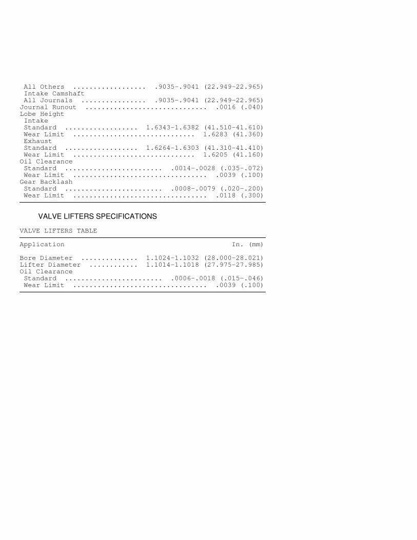
All Others .................. .9035-.9041 (22.949-22.965) Intake Camshaft All Journals ................ .9035-.9041 (22.949-22.965)Journal Runout .............................. .0016 (.040)Lobe Height Intake Standard .................. 1.6343-1.6382 (41.510-41.610) Wear Limit .............................. 1.6283 (41.360) Exhaust Standard .................. 1.6264-1.6303 (41.310-41.410) Wear Limit .............................. 1.6205 (41.160)Oil Clearance Standard ........................ .0014-.0028 (.035-.072) Wear Limit ................................. .0039 (.100)Gear Backlash Standard ........................ .0008-.0079 (.020-.200) Wear Limit ................................. .0118 (.300)�����������������������������������������������������������������������������������������������������������������������
VALVE LIFTERS SPECIFICATIONS
VALVE LIFTERS TABLE�����������������������������������������������������������������������������������������������������������������������Application In. (mm)
Bore Diameter .............. 1.1024-1.1032 (28.000-28.021)Lifter Diameter ............ 1.1014-1.1018 (27.975-27.985)Oil Clearance Standard ........................ .0006-.0018 (.015-.046) Wear Limit ................................. .0039 (.100)�����������������������������������������������������������������������������������������������������������������������


![1.5L 4-CYL - VIN [E]...1.5L 4-CYL - VIN [E] 1994 Toyota Paseo 1994 ENGINES Toyota 1.5L 4-Cylinder Paseo NOTE: For repair procedures not covered in this article, see ENGINE OVERHAUL](https://img.dokumen.tips/doc/110x75/5e9e94aeab46e3479946735d/15l-4-cyl-vin-e-15l-4-cyl-vin-e-1994-toyota-paseo-1994-engines-toyota.jpg)