Embed Size (px)
Citation preview
Towards Robust Behavioral Modeling of Reinforced Concrete Membersof Reinforced Concrete Members
K t O k lKutay Orakçal Boğaziçi Universitywith contributions of:
Denizhan Ulugtekin (M.Sc, B.U.) Tevfik Terzioglu (M.Sc. B.U.)S Reza Chowdhury (Ph D B U )S. Reza Chowdhury (Ph.D., B.U.)
International Workshop on“Role of ResearchInternational Workshop on Role of Research Infrastructures in Seismic Rehabilitation”
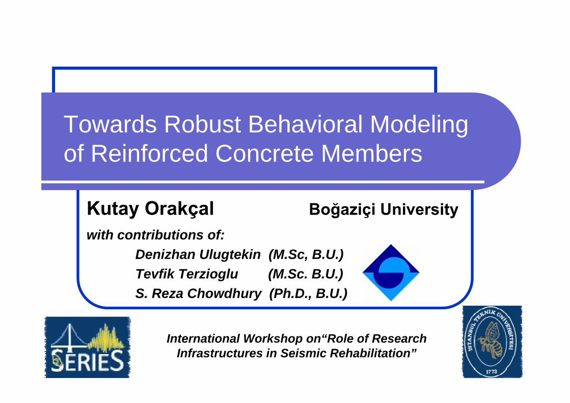
Structural ModelingStructural Modeling
Modern codes on performance-based i i t d d i iseismic assessment and design require
nonlinear response analysis of structures.
A l i l d l h ld hAnalytical models should represent the behavioral characteristics of the members at both global and local response levels.
gv&&
Examples of novel analytical modeling approaches to be presented for pp pnonlinear response simulation of RC members.
Emphasis on simulation of nonlinear flexural, shear, and bond-slip responses in RC columns and wallsin RC columns and walls
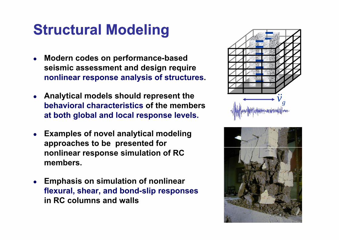
Modeling of Flexural Responses:Modeling of Flexural Responses:Th “MVLEM” f St t l W llTh “MVLEM” f St t l W ll
5 Rigid Beam
The “MVLEM” for Structural WallsThe “MVLEM” for Structural Walls
46 Rigid Beam
m . .
h
(1-c)hk1 k2 knkH. . . . . . .
2
. . . .
ch 1 2
12
3 Rigid Beam RC WALL WALL MODEL
k k k k k k kk1 2 3 4 5 6 7 8
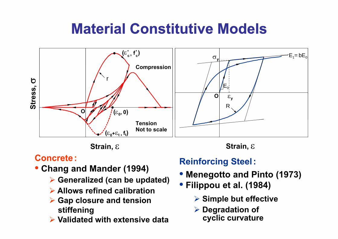
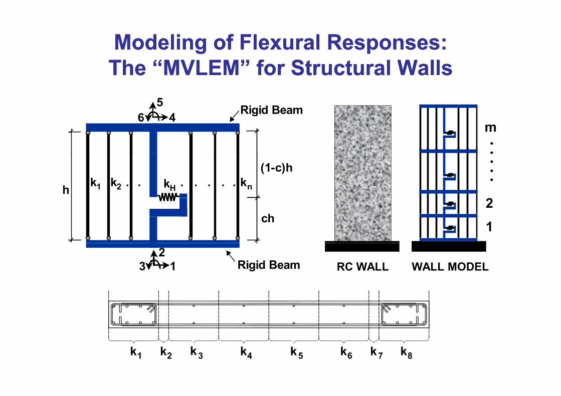
Material Constitutive ModelsMaterial Constitutive Models
C i
( εc ' , f c
' ) E1= bE0σy
Compression
rE0
ss, σ
O (ε0, 0)
εyO
RStre
s
Strain ε
TensionNot to scale(ε0+ εt , ft)
Strain εStrain, εConcrete :• Chang and Mander (1994)
Reinforcing Steel :• Menegotto and Pinto (1973)
Strain, ε
Generalized (can be updated)Allows refined calibrationGap closure and tension
• Menegotto and Pinto (1973)• Filippou et al. (1984)
Simple but effectiveGap closure and tensionstiffeningValidated with extensive data
Simple but effectiveDegradation of cyclic curvature

Experimental Experimental VerificationVerification of the Modelof the Modelpp
• Cyclic test results on slender rectangular and T-shaped wallspecimens (Thomsen and Wallace 1995)(Thomsen and Wallace, 1995)
• Approximately 1/4 scaleA t ti 3• Aspect ratio = 3
• Prototype building design (UBC)• Displacement – based
RW2sp ace e t based
evaluation for detailing• 3.66 m x 122 cm x 10 cm
• Loading:Constant axial loadCCyclic lateral load applied at top of walls
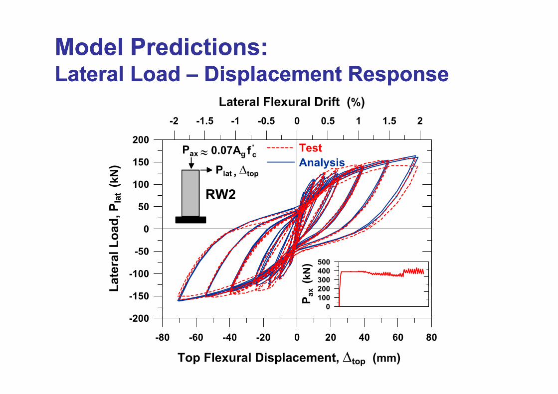
Model PredictionsModel Predictions::
Lateral Flexural Drift (%)
Lateral Load Lateral Load –– Displacement ResponseDisplacement Response
200
-2 -1.5 -1 -0.5 0 0.5 1 1.5 2
( )
Test≈Pax 0 07A f '
100
150
at (
kN) Analysis
≈Pax 0.07Ag f c
Plat , Δtop
RW2
0
50
Load
, Pla RW2
-100
-50
Late
ral L
200300400500
(kN
)-200
-150
L
0100200
P ax
-80 -60 -40 -20 0 20 40 60 80
Top Flexural Displacement, Δtop (mm)
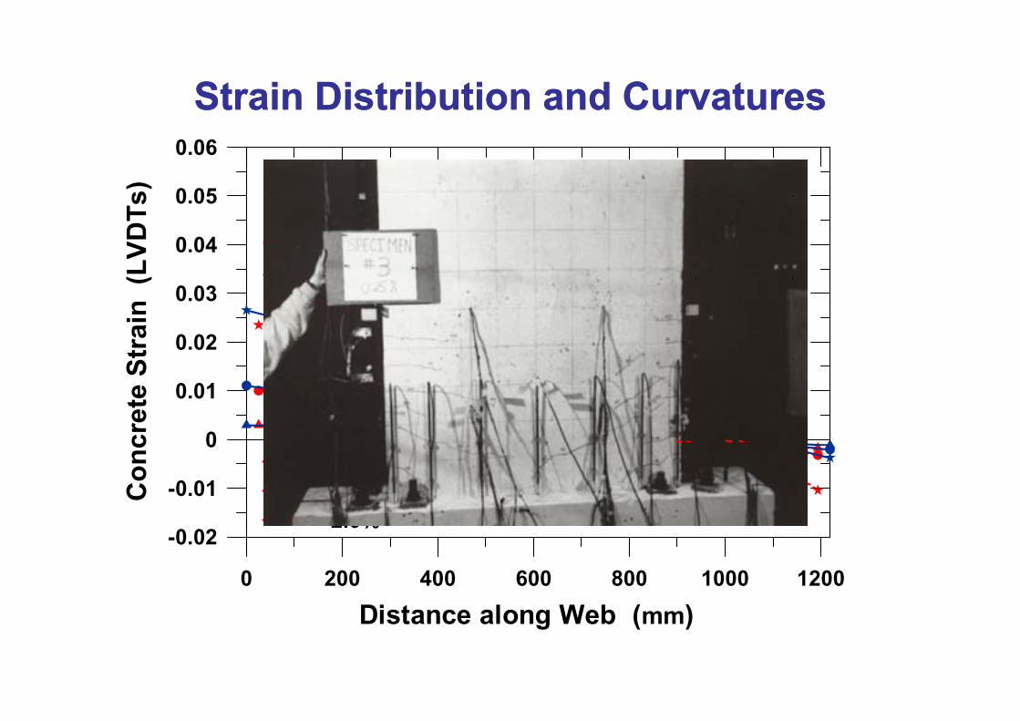
Strain Distribution and Strain Distribution and CurvatureCurvaturess
0 05
0.06s) 0.0025RW2
0.04
0.05
(LVD
Ts
TestAnalysis
-0.0025
0RW2
0.02
0.03
Stra
in ( Analysis
0 01
-0.0075
-0.005
0
0.01
cret
e S -0.01
-0.01
0
Con
c
0.5%1.0%2 0%
0 200 400 600 800 1000 1200
Di t l W b ( )
-0.022.0%
Distance along Web (mm)
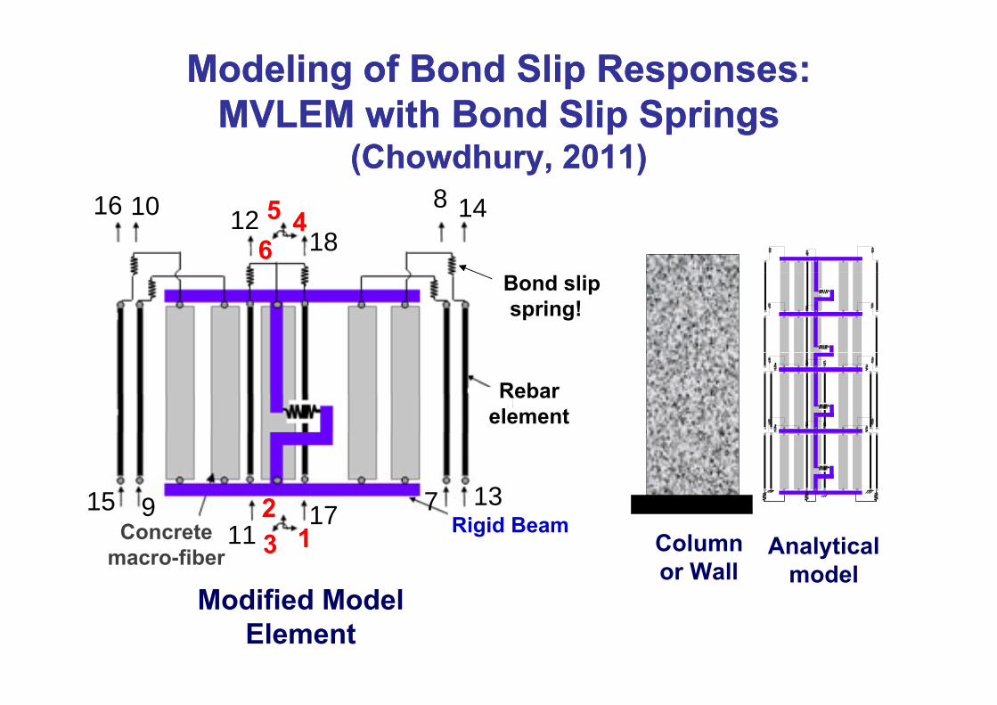
Modeling of Bond Slip Responses:Modeling of Bond Slip Responses:MVLEM with Bond Slip SpringsMVLEM with Bond Slip Springs
8
MVLEM with Bond Slip SpringsMVLEM with Bond Slip Springs(Chowdhury, 2011)(Chowdhury, 2011)
14 818
45 6
12 1016
Bond slip spring!
Rebar element
2 17915 137
M difi d M d l
Column or Wall
Analytical model
1 2 3 11
179
Rigid BeamConcretemacro-fiber
Modified Model Element

Constitutive Bond Stress vs. Slip Constitutive Bond Stress vs. Slip ModelsModelsSt
ress
Bon
d S
Roman Aqueduct, FranceSplitting Pullout
q19 B.C.
Splitting Pull-out
Slip DeformationSlip Deformation
gHarajli et al. (2009)Unconfined and partially-
fi d t
Eligehausen et al. (1983) Confined concrete, in vicinity
f ticonfined concreteExperimentally-validated
of tiesExperimentally-validated
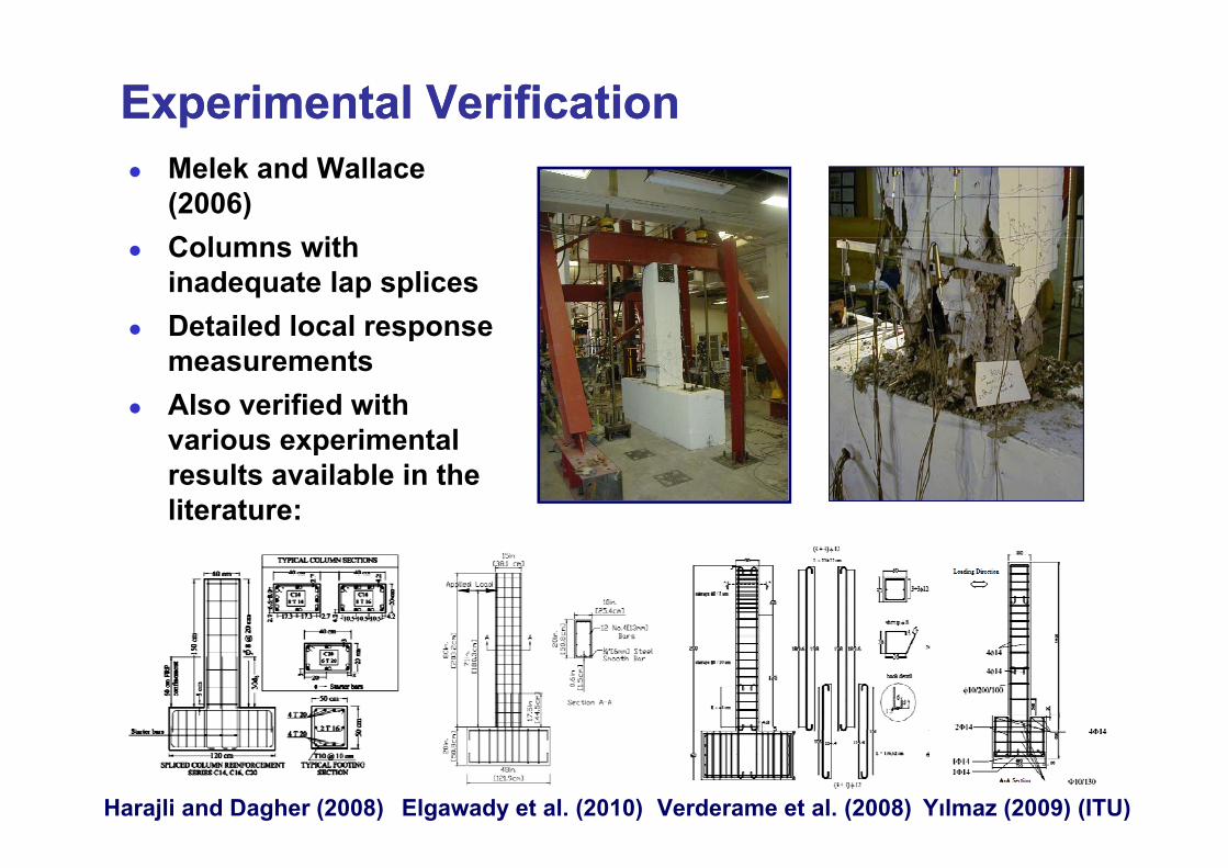
Experimental VerificationExperimental VerificationMelek and Wallace(2006)C l ithColumns with inadequate lap splicesDetailed local responseDetailed local response measurementsAlso verified with
i i t l
Roman Aqueduct, France
various experimental results available in the literature: q
19 B.C.
Harajli and Dagher (2008) Elgawady et al. (2010) Verderame et al. (2008) Yılmaz (2009) (ITU)
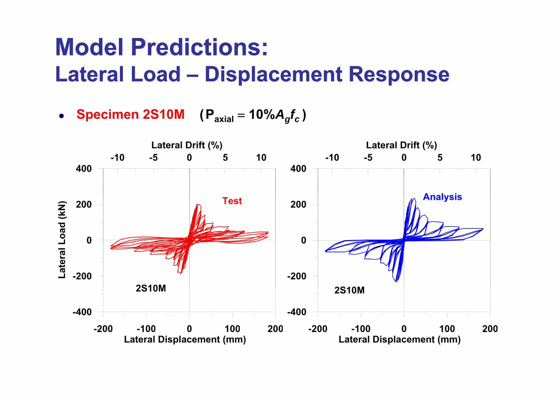
Model PredictionsModel Predictions::Lateral Load Lateral Load –– Displacement ResponseDisplacement Response
Specimen 2S10M (Paxial = 10%Agfc )
Lateral Drift (%) Lateral Drift (%)
400-10 -5 0 5 10
T t
400-10 -5 0 5 10
Analysis
Roman Aqueduct, France0
200
Load
(kN
) Test
0
200Analysis
q19 B.C.
-200
0
Late
ral L
2S10M-200
0
2S10M
-200 -100 0 100 200
-400
2S10M
-200 -100 0 100 200
-400
2S10M
00 00 0 00 00Lateral Displacement (mm)
00 00 0 00 00Lateral Displacement (mm)
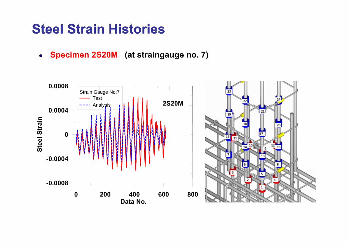
SteelSteel Strain HistoriesStrain Histories
Specimen 2S20M (at straingauge no. 7)
0.0008Strain Gauge No:7
0.0004
ain
TestAnalysis 2S20M
0
Stee
l Str
a
-0.0004
S
0 200 400 600 800Data No.
-0.0008
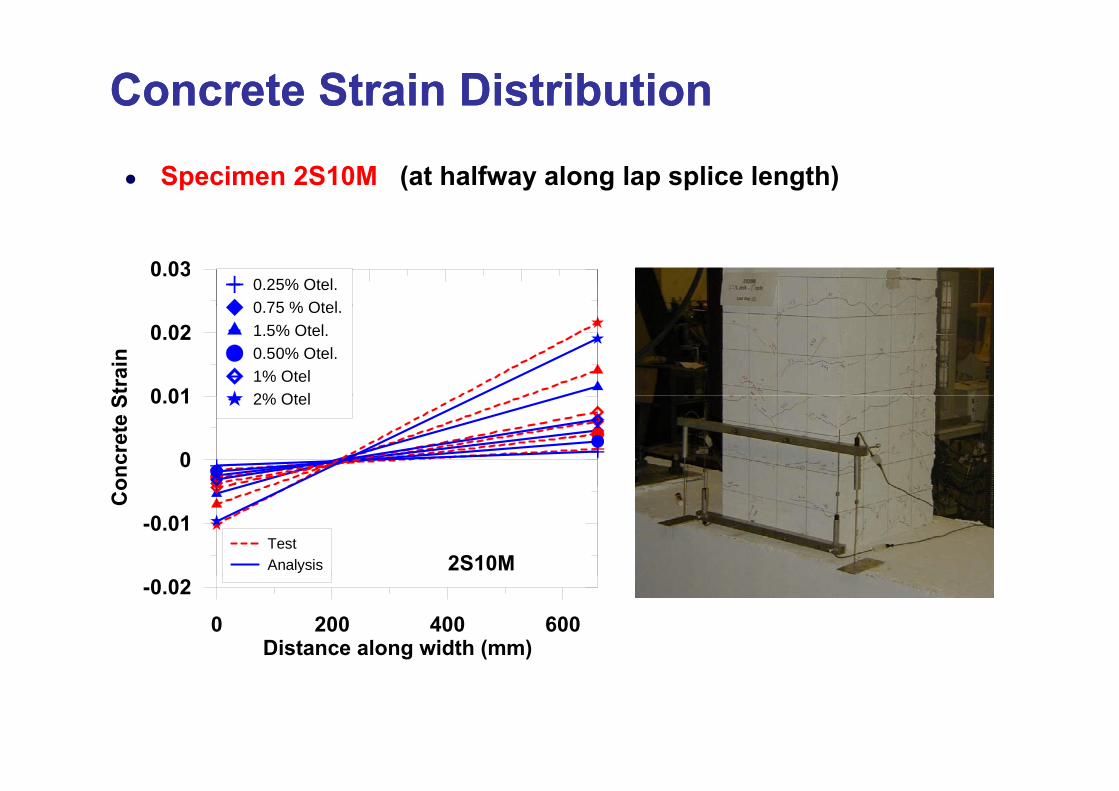
Concrete Strain DistributionConcrete Strain Distribution
Specimen 2S10M (at halfway along lap splice length)
0.030.25% Otel.0 75 % Otel
0 01
0.02
Stra
in
0.75 % Otel.1.5% Otel.0.50% Otel.1% Otel2% Ot l
0
0.01
oncr
ete
S 2% Otel
-0.01
Co
TestAnalysis 2S10M
0 200 400 600Distance along width (mm)
-0.02
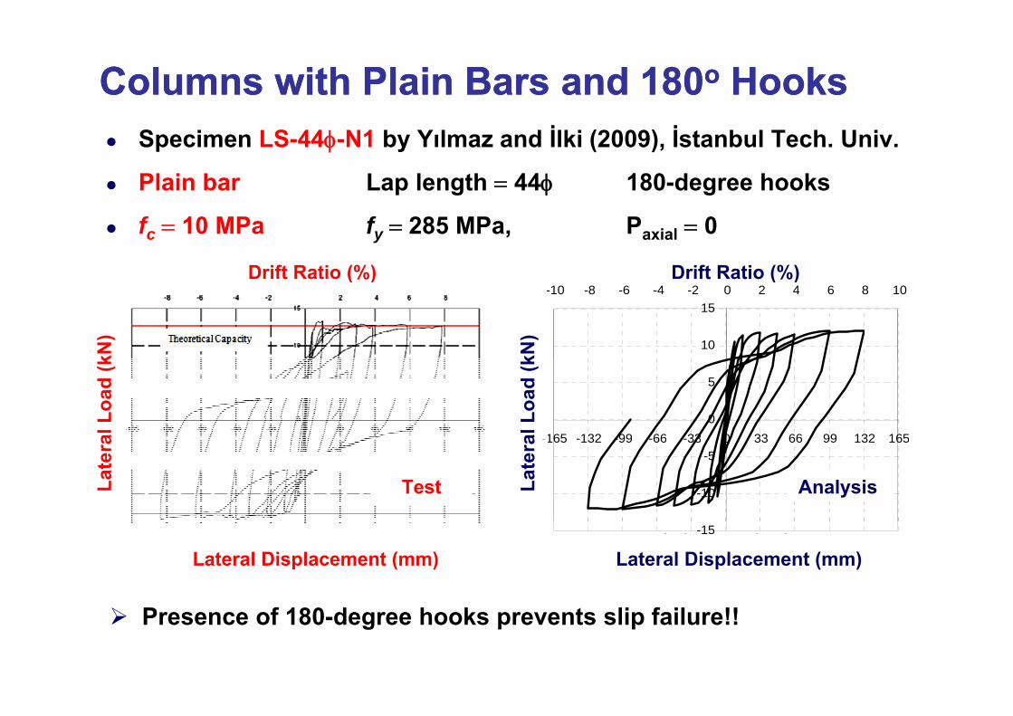
Columns with Plain Bars and 180Columns with Plain Bars and 180oo HooksHooksSpecimen LS-44φ-N1 by Yılmaz and İlki (2009), İstanbul Tech. Univ.
Plain bar Lap length = 44φ 180-degree hooks
fc = 10 MPa fy = 285 MPa, Paxial = 0
Drift Ratio (%) Drift Ratio (%)
10
15-10 -8 -6 -4 -2 0 2 4 6 8 10
kN)
Drift Ratio (%)
kN)
Drift Ratio (%)
()
0
5
-165 -132 -99 -66 -33 0 33 66 99 132 165al L
oad
(k
al L
oad
(k
-10
-5-165 -132 -99 -66 -33 0 33 66 99 132 165
Late
ra
Test AnalysisLate
raDi l ( )
-15
Lateral Displacement (mm) Lateral Displacement (mm)
Presence of 180-degree hooks prevents slip failure!!
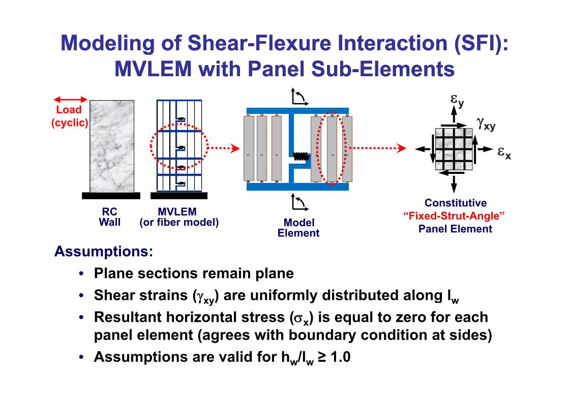
Modeling of ShearModeling of Shear--FlexureFlexure Interaction (SFI):Interaction (SFI):MVLEM ith P l S bMVLEM ith P l S b El tEl t
Load εy
MVLEM with Panel SubMVLEM with Panel Sub--ElementsElementsLoad
(cyclic) γxy
εx
Constitutive
εx
MVLEM(or fiber model)
RCWall
Constitutive“Fixed-Strut-Angle”
Panel Element
A ti
ModelElement
Assumptions:• Plane sections remain plane
Shear strains ( ) are niforml distrib ted along l• Shear strains (γxy) are uniformly distributed along lw• Resultant horizontal stress (σx) is equal to zero for each
panel element (agrees with boundary condition at sides)panel element (agrees with boundary condition at sides)• Assumptions are valid for hw/lw ≥ 1.0
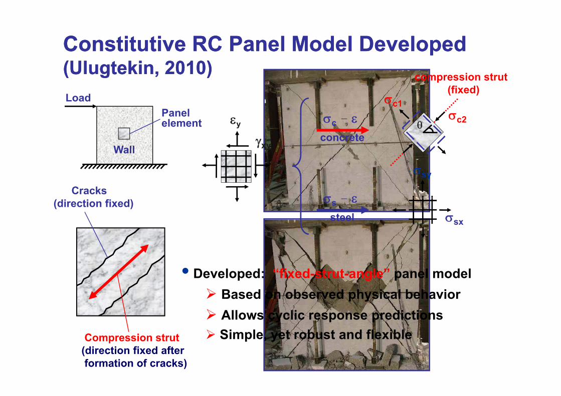
Constitutive RC Panel Model DevelopedConstitutive RC Panel Model Developed(Ul t ki 2010)(Ul t ki 2010)(Ulugtekin, 2010)(Ulugtekin, 2010)Load σc1
compression strut(fixed)
Wall
Panelelement σc - ε
concrete
σc2θεy
γxy
Cracks
Wall
σsyεx
σ ε(direction fixed)σsx
σs - εsteel
• Developed: “fixed-strut-angle” panel modelBased on observed physical behaviorAllows cyclic response predictionsSimple yet robust and flexibleCompression strut
(direction fixed after formation of cracks)
Simple, yet robust and flexible
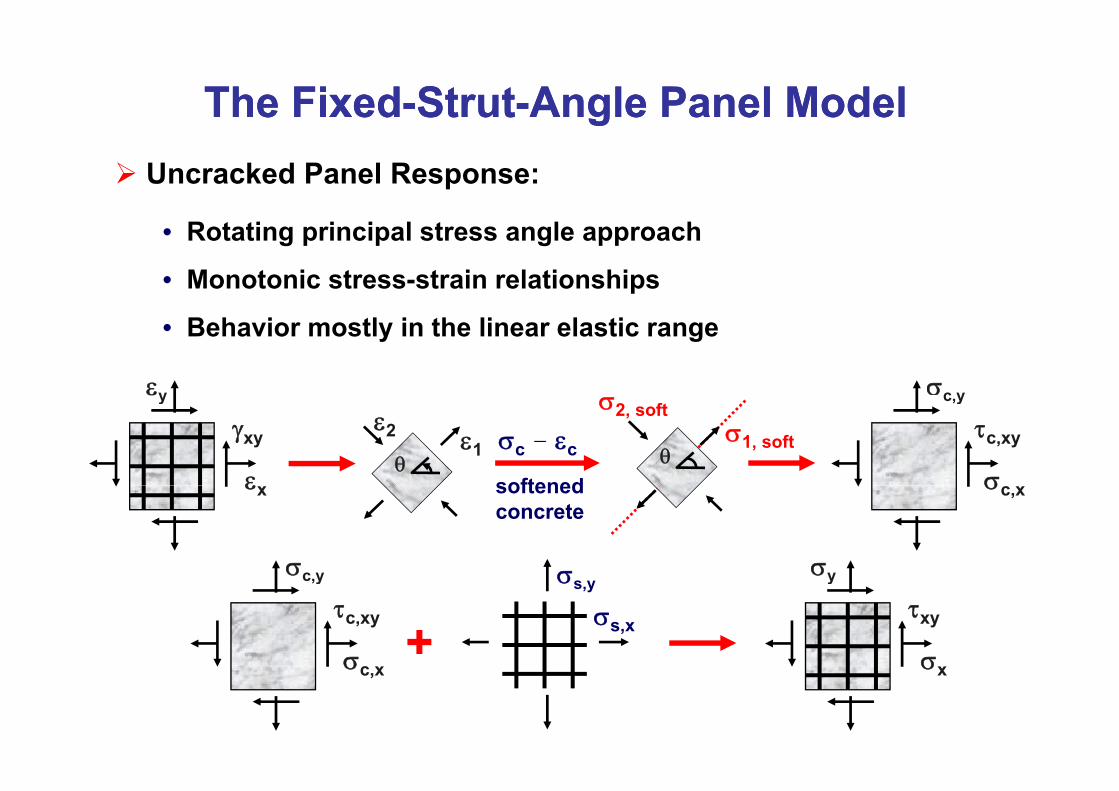
The FixedThe Fixed--StrutStrut--AAngle Panel Modelngle Panel ModelUncracked Panel Response:
• Rotating principal stress angle approach
• Monotonic stress-strain relationships
εy
• Behavior mostly in the linear elastic range
σc y
ε
γxy
y
σc – εc
softened
σ1, soft
σ2, soft
θε1
ε2
θσ
τc,xy
c,y
εx softened concrete
σy
σc,x
σc y σ
σ
τxy
σy
σ
τc,xy
σc,y
σs,x
σs,y
+ σxσc,x
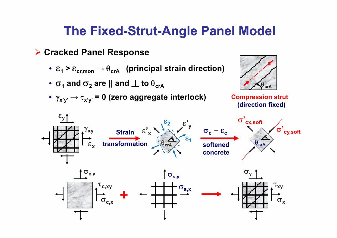
The FixedThe Fixed--StrutStrut--AAngle Panel Modelngle Panel ModelCracked Panel Response
• ε1 > εcr,mon → θcrA (principal strain direction)
• σ1 and σ2 are || and ┴ to θcrA θcrA
εy
• γx’y’ → τx’y’ = 0 (zero aggregate interlock)
σ’
Compression strut (direction fixed)
εx
γxy
y
σc – εc
softened
σ’cy,soft
σ cx,soft
θcrA
ε’yε’x
θcrA
ε2
ε1Strain
transformationεx softened concrete
crA
σyσc y σ
t a s o at o
σ
τxy
σy
σ
τc,xy
σc,y
σs,x
σs,y
+ σxσc,x
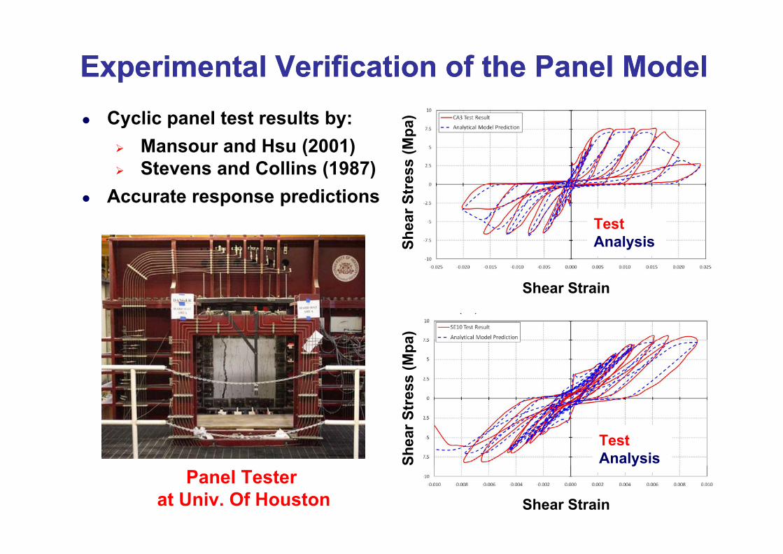
Experimental Verification of the Panel ModelExperimental Verification of the Panel Model
(Mpa
)Cyclic panel test results by:Mansour and Hsu (2001)
r Str
ess
(Mansour and Hsu (2001)Stevens and Collins (1987)
Accurate response predictions
Shea Test
Analysis
a)
Shear Strain
ress
(Mpa
Shea
r Str
TestAnalysis
Shear Strain
yPanel Tester
at Univ. Of Houston
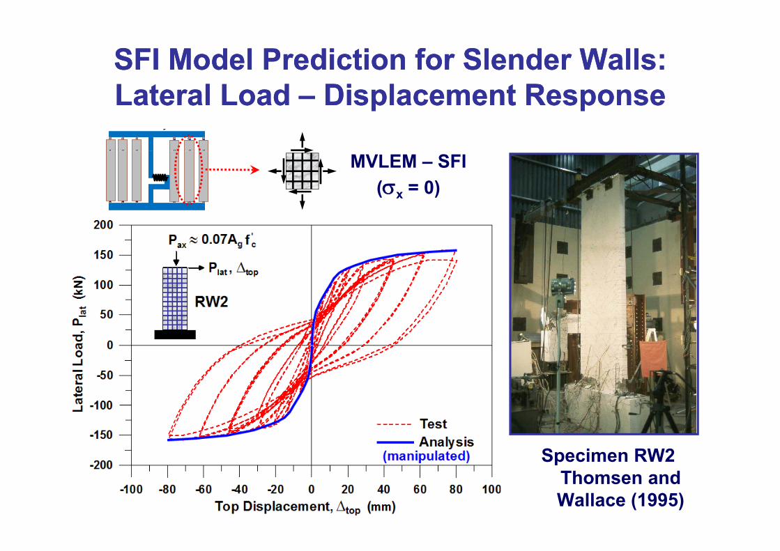
SFI Model Prediction for Slender Walls:SFI Model Prediction for Slender Walls:L t l L dL t l L d Di l t RDi l t RLateral Load Lateral Load –– Displacement ResponseDisplacement Response
MVLEM – SFI(σx = 0)
Specimen RW2 pThomsen and Wallace (1995)
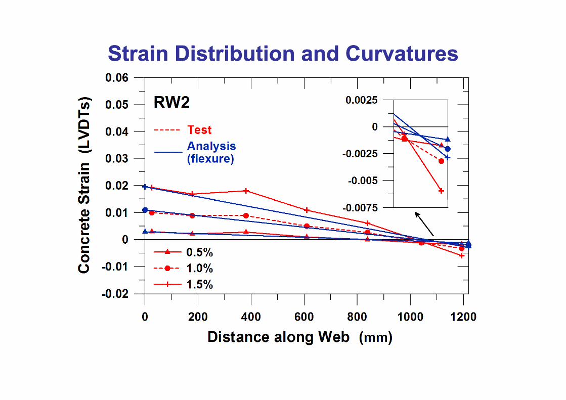
Strain Distribution and CurvaturesStrain Distribution and Curvatures
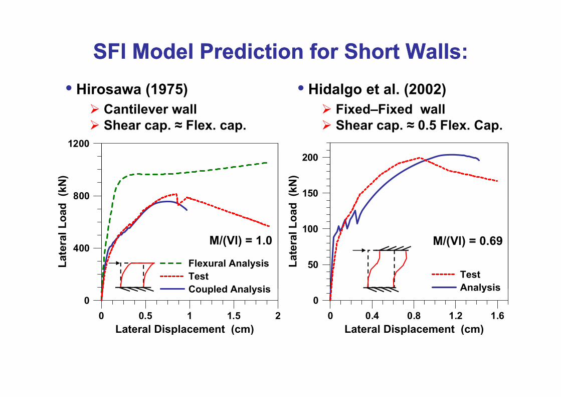
SFI Model Prediction for Short Walls:SFI Model Prediction for Short Walls:• Hirosawa (1975)
Cantilever wall• Hidalgo et al. (2002)
Fixed Fixed wall
1200
Cantilever wallShear cap. ≈ Flex. cap.
Fixed–Fixed wallShear cap. ≈ 0.5 Flex. Cap.
150
200
(kN
)
800(kN
)
100
ral L
oad
M/(Vl) = 0.69
800
ral L
oad
M/(Vl) = 1.0
50Late
r
TestAnalysis
M/(Vl) 0.69400
Late
r
Flexural AnalysisTestCoupled Analysis
M/(Vl) 1.0
0 0.4 0.8 1.2 1.6Lateral Displacement (cm)
0Analysis
0 0.5 1 1.5 2Lateral Displacement (cm)
0Coupled Analysis
p ( )p ( )
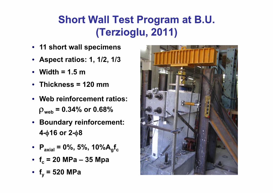
Short Wall Test Program at B.U.Short Wall Test Program at B.U.(Terzioglu 2011)(Terzioglu 2011)(Terzioglu, 2011)(Terzioglu, 2011)
• 11 short wall specimens
• Aspect ratios: 1, 1/2, 1/3
• Width = 1.5 m
• Thickness = 120 mm
W b i f t ti• Web reinforcement ratios:ρweb = 0.34% or 0.68%
• Boundary reinforcement: 4-φ16 or 2-φ8
• Paxial = 0%, 5%, 10%Agfc
• fc = 20 MPa – 35 Mpac p
• fy = 520 MPa
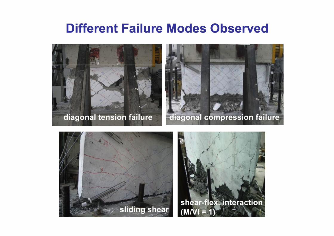
Different Failure Modes ObservedDifferent Failure Modes Observed
diagonal tension failure diagonal compression failurediagonal tension failure diagonal compression failure
sliding shearshear-flex. interaction(M/Vl = 1)
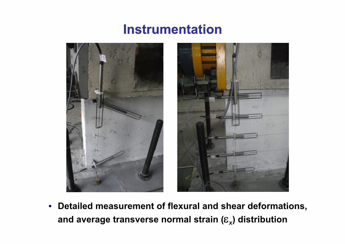
InstrumentationInstrumentation
• Detailed measurement of flexural and shear deformations• Detailed measurement of flexural and shear deformations, and average transverse normal strain (εx) distribution
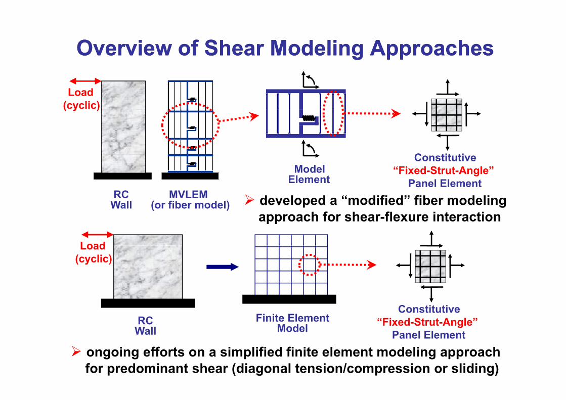
Overview of Shear Modeling ApproachesOverview of Shear Modeling Approaches
Load(cyclic)
( y )
C tit ti
MVLEMRC
ModelElement
Constitutive“Fixed-Strut-Angle”
Panel Elementdeveloped a “modified” fiber modeling
Load
(or fiber model)Wall developed a modified fiber modeling approach for shear-flexure interaction
Load(cyclic)
RCWall
Finite ElementModel
Constitutive“Fixed-Strut-Angle”
Panel ElementPanel Elementongoing efforts on a simplified finite element modeling approach for predominant shear (diagonal tension/compression or sliding)
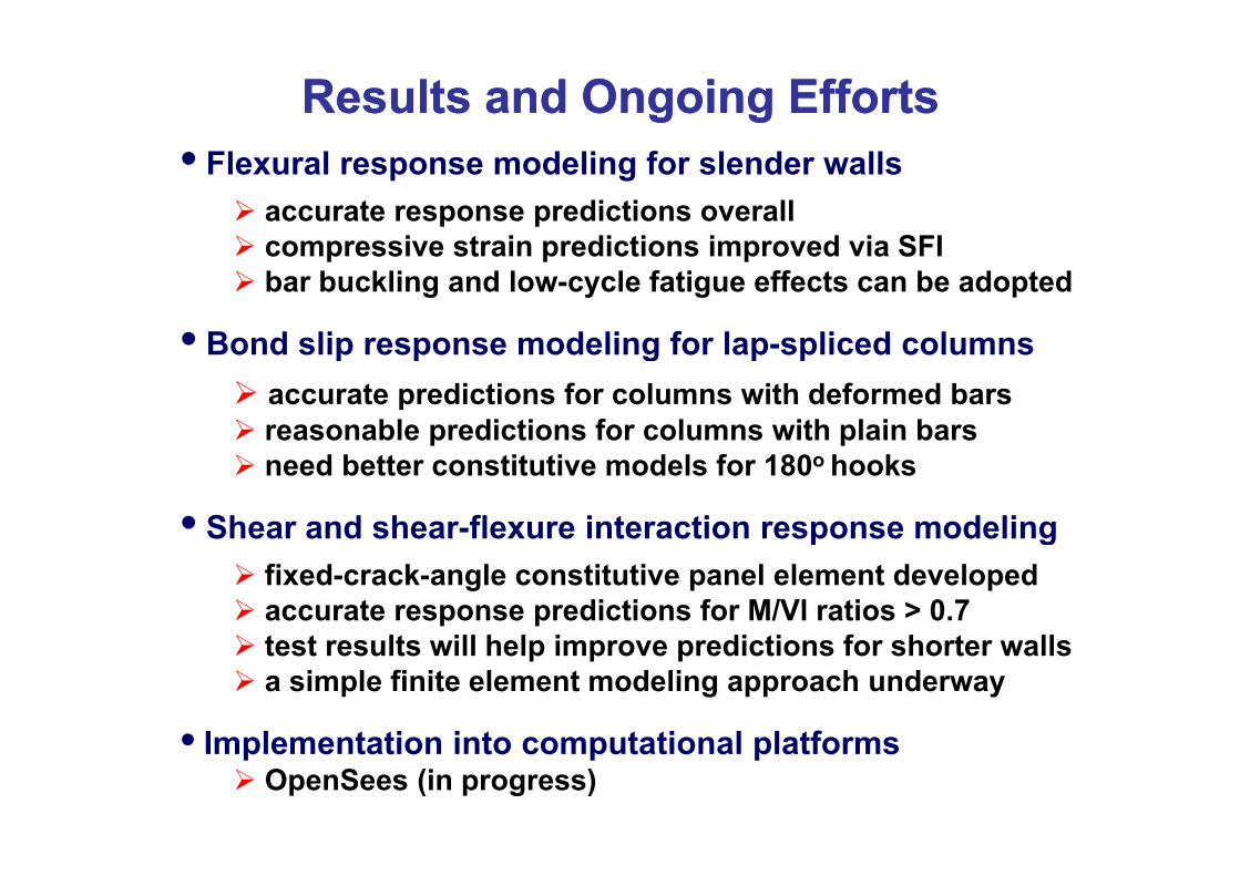
Results and Ongoing EffortsResults and Ongoing Efforts• Flexural response modeling for slender walls
accurate response predictions overalli t i di ti i d i SFIcompressive strain predictions improved via SFI
bar buckling and low-cycle fatigue effects can be adopted
• Bond slip response modeling for lap spliced columns• Bond slip response modeling for lap-spliced columnsaccurate predictions for columns with deformed barsreasonable predictions for columns with plain barsreasonable predictions for columns with plain bars need better constitutive models for 180o hooks
• Shear and shear-flexure interaction response modelingShear and shear flexure interaction response modelingfixed-crack-angle constitutive panel element developed accurate response predictions for M/Vl ratios > 0.7t t lt ill h l i di ti f h t lltest results will help improve predictions for shorter wallsa simple finite element modeling approach underway
• I l t ti i t t ti l l tf• Implementation into computational platformsOpenSees (in progress)
Towards Robust Behavioral Modeling of Reinforced Concrete Membersof Reinforced Concrete Members
K t O k lKutay Orakçal Boğaziçi Universitywith contributions of:
Denizhan Ulugtekin (M.Sc, B.U.) Tevfik Terzioglu (M.Sc. B.U.)S Reza Chowdhury (Ph D B U )S. Reza Chowdhury (Ph.D., B.U.)
International Workshop on“Role of ResearchInternational Workshop on Role of Research Infrastructures in Seismic Rehabilitation”